THERMOSALD ISX-LC / IPX-LC
30
3E S.r.l. - Via del Maccabreccia 37/a - 40012 LIPPO DI CALDERARA (BOLOGNA) Tel. ++39 051 6466225-228 E-Mail: [email protected] Fax ++39 051 6426252 Pagina web: www.3e3e3e.com THERMOSALD ISX-LC / IPX-LC THERMOREGULATOR LOW COST FOR IMPULSE SEALING TECHNICAL FEATURES - THERMOREGULATOR LOW COST OF THE LINE THERMOSALD ISX-IPX WITH THE SAME STRUCTURE MECHANICAL AND CONNECTIONS - SET OF PREHEAT AND SEAL TEMPERATURE BY POTENTIOMETER OR ANALOG OUT OF PLC - ANALOG OUTPUT 0-5V TO PLC FOR SEALING TEMPERATURE AND ALARMS - NO CONNECTIONS TO THE DISPLAY - COMPLETELY AUTOMATIC CALIBRATING - COMPLETELY DIAGNOSTIC FOR TROUBLESHOOTING - LOW VOLTAGE SUPPLY 24VDC - WORKING VOLTAGES FROM 230 TO 600 VOLTS - WORKING CURRENTS FROM 10 TO 400 AMPERE - RAM DATA CHECK IN RUN TIME (v4.4) - COMPATIBILITY WITH ALL PREVIOUS ANALOG MODELS INSTALLATION AND USER MANUAL (V4)
Transcript of THERMOSALD ISX-LC / IPX-LC

3E S.r.l. - Via del Maccabreccia 37/a - 40012 LIPPO DI CALDERARA (BOLOGNA) Tel. ++39 051 6466225-228 E-Mail: [email protected] Fax ++39 051 6426252 Pagina web: www.3e3e3e.com
THERMOSALD ISX-LC / IPX-LC
THERMOREGULATOR LOW COST
FOR IMPULSE SEALING
TECHNICAL FEATURES - THERMOREGULATOR LOW COST OF THE LINE THERMOSALD ISX-IPX WITH THE SAME STRUCTURE MECHANICAL AND CONNECTIONS - SET OF PREHEAT AND SEAL TEMPERATURE BY POTENTIOMETER OR ANALOG OUT OF PLC - ANALOG OUTPUT 0-5V TO PLC FOR SEALING TEMPERATURE AND ALARMS - NO CONNECTIONS TO THE DISPLAY - COMPLETELY AUTOMATIC CALIBRATING - COMPLETELY DIAGNOSTIC FOR TROUBLESHOOTING - LOW VOLTAGE SUPPLY 24VDC - WORKING VOLTAGES FROM 230 TO 600 VOLTS - WORKING CURRENTS FROM 10 TO 400 AMPERE - RAM DATA CHECK IN RUN TIME (v4.4) - COMPATIBILITY WITH ALL PREVIOUS ANALOG MODELS
INSTALLATION AND USER MANUAL (V4)
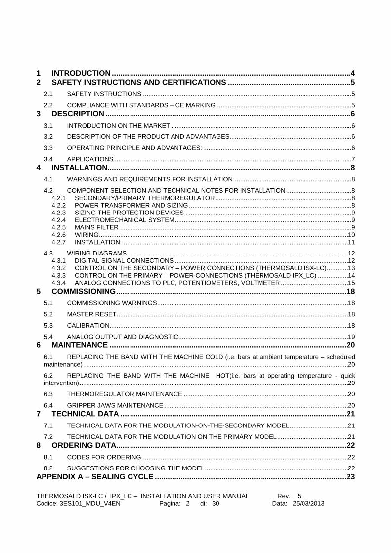
THERMOSALD ISX-LC / IPX_LC – INSTALLATION AND USER MANUAL Rev. 5 Codice: 3ES101_MDU_V4EN Pagina: 2 di: 30 Data: 25/03/2013
1 INTRODUCTION ............................................................................................................... 4 2 SAFETY INSTRUCTIONS AND CERTIFICATIONS ............ ............................................. 5
2.1 SAFETY INSTRUCTIONS ...................................................................................................................... 5
2.2 COMPLIANCE WITH STANDARDS – CE MARKING ............................................................................ 5 3 DESCRIPTION .................................................................................................................. 6
3.1 INTRODUCTION ON THE MARKET ...................................................................................................... 6
3.2 DESCRIPTION OF THE PRODUCT AND ADVANTAGES ..................................................................... 6
3.3 OPERATING PRINCIPLE AND ADVANTAGES: .................................................................................... 6
3.4 APPLICATIONS ...................................................................................................................................... 7 4 INSTALLATION....................................... .......................................................................... 8
4.1 WARNINGS AND REQUIREMENTS FOR INSTALLATION ................................................................... 8
4.2 COMPONENT SELECTION AND TECHNICAL NOTES FOR INSTALLATION ..................................... 8 4.2.1 SECONDARY/PRIMARY THERMOREGULATOR ............................................................................. 8 4.2.2 POWER TRANSFORMER AND SIZING ............................................................................................ 8 4.2.3 SIZING THE PROTECTION DEVICES .............................................................................................. 9 4.2.4 ELECTROMECHANICAL SYSTEM .................................................................................................... 9 4.2.5 MAINS FILTER ................................................................................................................................... 9 4.2.6 WIRING ............................................................................................................................................. 10 4.2.7 INSTALLATION ................................................................................................................................. 11
4.3 WIRING DIAGRAMS ............................................................................................................................. 12 4.3.1 DIGITAL SIGNAL CONNECTIONS .................................................................................................. 12 4.3.2 CONTROL ON THE SECONDARY – POWER CONNECTIONS (THERMOSALD ISX-LC) ............ 13 4.3.3 CONTROL ON THE PRIMARY – POWER CONNECTIONS (THERMOSALD IPX_LC) ................. 14 4.3.4 ANALOG CONNECTIONS TO PLC, POTENTIOMETERS, VOLTMETER ...................................... 15
5 COMMISSIONING ........................................................................................................... 18
5.1 COMMISSIONING WARNINGS ............................................................................................................ 18
5.2 MASTER RESET ................................................................................................................................... 18
5.3 CALIBRATION....................................................................................................................................... 18
5.4 ANALOG OUTPUT AND DIAGNOSTIC ................................................................................................ 19 6 MAINTENANCE ....................................... ....................................................................... 20
6.1 REPLACING THE BAND WITH THE MACHINE COLD (i.e. bars at ambient temperature – scheduled maintenance) ...................................................................................................................................................... 20
6.2 REPLACING THE BAND WITH THE MACHINE HOT(i.e. bars at operating temperature - quick intervention) ........................................................................................................................................................ 20
6.3 THERMOREGULATOR MAINTENANCE ............................................................................................. 20
6.4 GRIPPER JAWS MAINTENANCE ........................................................................................................ 20 7 TECHNICAL DATA .................................... ..................................................................... 21
7.1 TECHNICAL DATA FOR THE MODULATION-ON-THE-SECONDARY MODEL ................................. 21
7.2 TECHNICAL DATA FOR THE MODULATION ON THE PRIMARY MODEL ........................................ 21 8 ORDERING DATA ..................................... ...................................................................... 22
8.1 CODES FOR ORDERING ..................................................................................................................... 22
8.2 SUGGESTIONS FOR CHOOSING THE MODEL ................................................................................. 22 APPENDIX A – SEALING CYCLE ........................ ................................................................. 23

THERMOSALD ISX-LC / IPX_LC – INSTALLATION AND USER MANUAL Rev. 5 Codice: 3ES101_MDU_V4EN Pagina: 3 di: 30 Data: 25/03/2013
APPENDIX D – LIST OF ALARMS AND MESSAGES (CAUSES – REMEDIES).................. 24 APPENDIX E – MECHANICAL DIMENSIONS ................ ....................................................... 28 APPENDIX F – TABLE OF BANDS ....................... ................................................................ 29 APPENDIX G – COMMISSIONING SHEET ........................................................................... 30
THERMOSALD ISX-LC / IPX_LC – INSTALLATION AND USER MANUAL Rev. 5 Codice: 3ES101_MDU_V4EN Pagina: 4 di: 30 Data: 25/03/2013
1 INTRODUCTION This manual is the only complete document concerning the product represented on the front page. It contains safety instructions, a description of the device and some of its possible applications, instructions for installing, commissioning, servicing and disposing of the product, the codes and some examples for placing orders. This manual is referred to in all the documents that accompany the product and must be consulted before using the product described. In particular, read the instructions related to safety, installation, commissioning, servicing and disposal before using the product. REVISION OF THE MANUAL: Rev.: 0 Data: 15/06/2011 Software V1.0 - V3.2 Rev.: 1 Data: 07/11/2011 Software V3.3 Rev.: 2 Data: 16/02/2012 Software V4.0 Rev.: 3 Data: 20/06/2012 Software V4.2 Rev.: 4 Data: 03/12/2012 Software V4.3 Rev.: 5 Data: 25/03/2013 Software V4.4

THERMOSALD ISX-LC / IPX_LC – INSTALLATION AND USER MANUAL Rev. 5 Codice: 3ES101_MDU_V4EN Pagina: 5 di: 30 Data: 25/03/2013
2 SAFETY INSTRUCTIONS AND CERTIFICATIONS
2.1 SAFETY INSTRUCTIONS - A proper specific and technical knowledge is required to install, commission, service or use the product. Consult this “USER MANUAL” and follow the instructions contained herein in compliance with the SAFETY REGULATIONS. - Improper use of the apparatus may result in dangerous conditions for the operator and things and people nearby. - Do not use the equipment in an explosive atmosphere or with explosive material. - Do not use the equipment with flammable material without first taking the necessary safety precautions. - Install and use the thermoregulator only in industrial applications. - Use bands or wires with an appropriate positive temperature coefficient ( >= 8 x 10E-4 , 800ppm/K). - Do not change the temperature coefficient unless you have sufficient know how. - Mechanically fix the thermoregulator to the plate using the fixing holes. - Before connecting it to the mains, connect the ground protection conductor to the fixing bolt which is identified by a yellow-green PE indicator on the heat sink. - Do not connect the power circuit of the thermoregulator when the machine’s mechanical guards are open. - Do not power the thermoregulator if the protective cover has been removed. - After a MASTER RESET procedure has been performed, set the parameters correctly before using the equipment.
2.2 COMPLIANCE WITH STANDARDS – CE MARKING Il dispositivo è conforme ai requisiti essenziali delle seguenti Direttive Comunitarie applicabili al prodotto, in riferimento alle seguenti normative armonizzate: The device complies with the fundamental requirements set forth in the following European Directives that apply to the product with reference to the harmonized standards below: 89/336/EEC EMC Directive and subsequent amendments 92/31/ECC and 93/68/EEC CEI EN 55022 – Electromagnetic Compatibility (EMC) – Emission for industrial environments CEI EN 61000-6-2 – Electromagnetic Compatibility (EMC) – Part 6-2: Generic Standards - Immunity for industrial environments 73/23/EEC /LOW VOLTAGE Directive and subsequent amendments 93/68/EEC CEI EN 60204-1 – Safety of machinery – Electrical equipment of machines Part 1: General requirements

THERMOSALD ISX-LC / IPX_LC – INSTALLATION AND USER MANUAL Rev. 5 Codice: 3ES101_MDU_V4EN Pagina: 6 di: 30 Data: 25/03/2013
3 DESCRIPTION
3.1 INTRODUCTION ON THE MARKET THERMOSALD ISX-LC / IPX-LC are the lower cost thermoregulators of the modular line that can be configured and are compatible with one another. THERMOSALD ISX-LC / IPX-LC springs from the company’s long experience in the impulse sealing field and maintains total compatibility with all previous thermoregulators, namely THERMOSALD PWM, THERMOSALD SCR, THERMOSALD UPSCR and THERMOSALD ISC.
3.2 DESCRIPTION OF THE PRODUCT AND ADVANTAGES Like the previous impulse thermoregulators, THERMOSALD ISX – IPX can quickly heat a sealing band or cutting/sealing wire to the set temperature without using additional probes. This technology makes it possible to obtain very high working speeds for sealing polyethylene, polypropylene, environment-friendly products and plastics in general. The temperature is controlled directly on the sealing line and the temperature can be maintained even at high speeds. It avoids temperature drift between the first sealing operation and the next ones in production, it prevents the support bars from overheating, thus avoiding any subsequent mechanical problems caused by expansion. A cooling air blow and other precautions may further increase the speed and improve the sealing quality. Below is a list of the most important functional-technical features of the new THERMOSALD ISX-LC / IPX-LC:
- 24VNS insulated POWER SUPPLY: in the THERMOSALD ISX_LC version with control on the secondary, it allows the same thermoregulator to be used regardless of the mains voltage.
- POWER TRANSFORMER CONTROL ON THE SECONDARY OR PRIMARY: it allows the User to choose the best solution to the problem he/she has to solve within a voltage range of 230 to 600 Volts or current range of 150 to 400 Ampere. .
- ANALOG INPUT: analog input from potentiometer or PLC outputs for settino the preheat or seal temperature.
- ANALOG OUTPUT: analog output 0-5Volts to the PLC for sending the temperature of the sealing band or the alarms.
- COMPATIBILITY WITH ALL PREVIOUS THERMOREGULATORS: that allows spare parts to be replaced on obsolete models
- COMPLETELY AUTOMATIC CALIBRATION: just press the calibration button on the thermoregulator for 3 seconds or high the CALIBRATING INPUT for 3 seconds.
- GOOD DIAGNOSTICS FOR TROUBLESHOOTING: in case of alarm the leds of balance lamp to indicate exactly the number of alarm; a digital output more an analog output inform the PLC.
3.3 OPERATING PRINCIPLE AND ADVANTAGES:

THERMOSALD ISX-LC / IPX_LC – INSTALLATION AND USER MANUAL Rev. 5 Codice: 3ES101_MDU_V4EN Pagina: 7 di: 30 Data: 25/03/2013
At all network cycles THERMOSALD ISX – IPX reads the voltage and current on the band, calculates the resistance and then the temperature, which depends on the resistance, and controls the current that heats the band in a closed loop; this current is generated by a power transformer by means of phase control performed on the secondary of the power transformer in the THERMOSALD ISX configuration and on the primary of the power transformer in the THERMOSALD IPX configuration: selection can be made according to machine requirements or company situations. The new structure of the thermoregulator allows the user to operate without virtually having voltage or current limits as the problem shifts completely on to the power transformer and the system technical standards. For further information and details please refer to paragraph CONFIGURATIONS AND ADVANTAGES below.
3.4 APPLICATIONS On all packaging machines that require polyethylene, polypropylene, environment-friendly and plastic films to be sealed or cut/sealed, vertical and horizontal filling machines, bundling machines, shoppers, vacuum machines, etc.

THERMOSALD ISX-LC / IPX_LC – INSTALLATION AND USER MANUAL Rev. 5 Codice: 3ES101_MDU_V4EN Pagina: 8 di: 30 Data: 25/03/2013
4 INSTALLATION
4.1 WARNINGS AND REQUIREMENTS FOR INSTALLATION - BEFORE STARTING to INSTALL carefully read the SAFETY WARNINGS contained in this manual. - This apparatus must be installed in accordance with the requirements set forth in standard CEI - EN60204 - This apparatus must be installed carefully following the instructions contained in this USER MANUAL - This apparatus must be installed by skilled and properly trained personnel
4.2 COMPONENT SELECTION AND TECHNICAL NOTES FOR INS TALLATION (Please refer to the diagrams under paragraph 4.3) Below are the calculations to define the voltage and current required for the best application; select the suitable THERMOSALD ISX-LC / IPX-LC from the order table according to the values calculated. 4.2.1 SECONDARY/PRIMARY THERMOREGULATOR - The apparatus must be installed inside an electrical panel, protected against dust, water and corrosive acids. -The apparatus does not require special ventilation when used, but must be installed in a properly ventilated area; when the machine reaches steady-state operation, check that the heat sink of the thermoregulator does not exceed 60°C, if so, increase ventilation; a safety temperature probe is installed in models ISX2 and IPX2. 4.2.2 POWER TRANSFORMER AND SIZING - A power transformer suitable for the circulating currents must be envisaged to supply power to the sealing band as indicated in the diagrams (ref. par. 4.3); in the case of a overlapped winding transformer, place a shield between the primary and secondary to avoid mains leaks on the secondary -The power transformer can be sized simply using the thermoregulator’s panel (diagnosis menu – see description in the commissioning section) or as follows: Calculate the band cross-section CROSS-SECTION[sq.mm] = WIDTH[mm] x THICKNESS[mm] Calculate rated heating current Inom [A]= 30[A/sq.mm] x CROSS-SECTION[sq.mm] Calculate useful resistance Ru[ohm]=Specific resistance[ohm/m] x Useful length [m] Calculate the rated voltage and power Vnom[V]= Ru[ohm] x Inom [A], Pnom= Vnom x Inom. Follow the suggestions of the notes below:

THERMOSALD ISX-LC / IPX_LC – INSTALLATION AND USER MANUAL Rev. 5 Codice: 3ES101_MDU_V4EN Pagina: 9 di: 30 Data: 25/03/2013
NOTE1: maximum theoretical voltage VT and current IT of the transformer are calculated according to the machine’s speed requirements: a coefficient x 1.5, x 2, i.e. VT=Vnom x coefficient, IT=Inom x coefficient, can be applied. NOTE2: the maximum theoretical power of the transformer is calculated without considering the first full-wave heating impulses and according to a phase modulation mean factor, PT = VT x ITx 0.7 NOTE3: the actual mean power of the transformer depends on the number of sealing operations per minute, the ratio between the active state and sealing cycle period and the thickness of the film to be sealed; due to overall dimension reasons and costs, the PT theoretical power can be declassified introducing a SIF intermittent duty-type of the transformer (which, according to experience, should be about 50%-40%). NOTE: For support CONTACT our TECHNICAL OFFICE 4.2.3 SIZING THE PROTECTION DEVICES Envisage a D CURVE protection thermal magnetic circuit breaker to disconnect the mains as indicated in the diagrams (ref. par. 4.3). Calculate the breaking current = theoretical heating current IT divided by secondary-primary coils ratio Q. Ithermal magnetic circuit breaker = IT / Q NOTE1: the value of the protection device of the power transformer’s secondary must be the same as or higher than the calculated theoretical current IT; this protection device trips on the cables and band downstream of it. Considering that the thermoregulator is already fitted with an electronic protection device on the cables’ and band’s current, the fitter should analyze the possibility of not installing said protection device on the basis of the application. NOTE2: please note that the suggested protection devices must be verified by the designer according to the application. 4.2.4 ELECTROMECHANICAL SYSTEM -The safety chain must be made like the one in the base drawing (ref. par. 4.3). the emergency output contact must interrupt the power electromechanically; in particular, it must open the contactor necessary for interrupting the power transformer’s power supply. this contact must be suitable for the circulating currents; this interruption is crucial because if the electronic switch inside the thermoregulator fails (very rare event), only the contactor can prevent the bands from overheating and breaking. - Install an emergency button as indicated in the diagrams (ref. Par. 4.3). It must only be possible to reset this button manually and must be placed in a non-dangerous area that the operator can access easily. 4.2.5 MAINS FILTER -No cases of interference with equipment nearby have occurred with THERMOSALD ISX, phase control on the secondary. The system designer has to decide whether or not one single filter should be fitted at the input of the system for the entire machine according to the emission measurements taken on the mains. -A mains filter is recommended for THERMOSALD IPX, phase control on the secondary. The system designer has to decide whether or not one single filter should be fitted at the input of
THERMOSALD ISX-LC / IPX_LC – INSTALLATION AND USER MANUAL Rev. 5 Codice: 3ES101_MDU_V4EN Pagina: 10 di: 30 Data: 25/03/2013
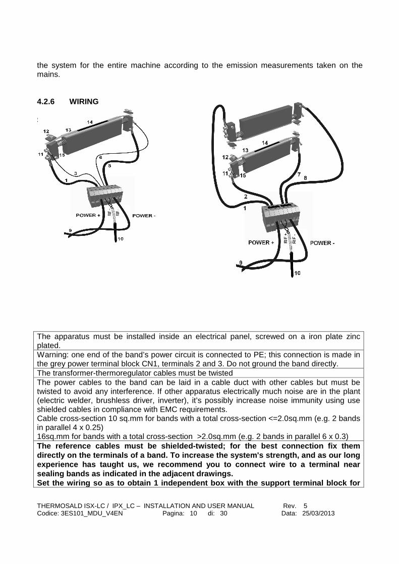
the system for the entire machine according to the emission measurements taken on the mains. 4.2.6 WIRING SINGLE BAND CONNECTION PARALLEL BAND CONNECTION The apparatus must be installed inside an electrical panel, screwed on a iron plate zinc plated. Warning: one end of the band’s power circuit is connected to PE; this connection is made in the grey power terminal block CN1, terminals 2 and 3. Do not ground the band directly. The transformer-thermoregulator cables must be twisted The power cables to the band can be laid in a cable duct with other cables but must be twisted to avoid any interference. If other apparatus electrically much noise are in the plant (electric welder, brushless driver, inverter), it’s possibly increase noise immunity using use shielded cables in compliance with EMC requirements. Cable cross-section 10 sq.mm for bands with a total cross-section <=2.0sq.mm (e.g. 2 bands in parallel 4 x 0.25) 16sq.mm for bands with a total cross-section >2.0sq.mm (e.g. 2 bands in parallel 6 x 0.3) The reference cables must be shielded-twisted; for the best connection fix them directly on the terminals of a band. To increase th e system's strength, and as our long experience has taught us, we recommend you to conne ct wire to a terminal near sealing bands as indicated in the adjacent drawings . Set the wiring so as to obtain 1 independent box wi th the support terminal block for

THERMOSALD ISX-LC / IPX_LC – INSTALLATION AND USER MANUAL Rev. 5 Codice: 3ES101_MDU_V4EN Pagina: 11 di: 30 Data: 25/03/2013
every thermoregulator so as to ensure that the cables of a thermoregulator do not get tangled with the cables of another thermoregulator or of another electrical noise units. In compliance with EMC requirements MAINS FILTER is not necessary on the application with control on the secondary 4.2.7 INSTALLATION Electrically disconnect the electrical panel and make sure no voltage is being supplied to the mains connection terminals. Screw the thermoregulator on the bottom of the electrical panel. Connect the ground wire (with the same cross-section as the power cables) to the thermoregulator’s PE bolt. Wire the power cables as described previously. Wire the reference cables as described previously. Perform the safety chain as described previously.

THERMOSALD ISX-LC / IPX_LC – INSTALLATION AND USER MANUAL Rev. 5 Codice: 3ES101_MDU_V4EN Pagina: 12 di: 30 Data: 25/03/2013
4.3 WIRING DIAGRAMS 4.3.1 DIGITAL SIGNAL CONNECTIONS
FU
SE
THERMOSALD
ISX-LC / IPX-LC
PR
EH
EA
T C
MD
SE
AL
ING
CM
D
RE
SE
T C
MD
CA
LIB
RA
TIO
N C
MD
0V
DC
24
VD
C
0VDC
ALARM
24
VD
C
1 sq.mm
THERMOSALD
ALARMEMERGENCY
CHAIN
CONSTRUCTION NOTES:
THERMOSALD ISX-LC / IPX_LC – INSTALLATION AND USER MANUAL Rev. 5 Codice: 3ES101_MDU_V4EN Pagina: 13 di: 30 Data: 25/03/2013
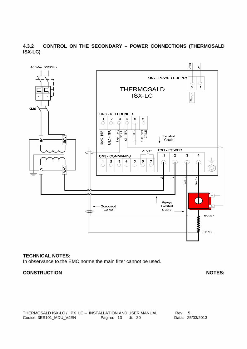
4.3.2 CONTROL ON THE SECONDARY – POWER CONNECTIONS (THERMOSALD ISX-LC)
TECHNICAL NOTES: In observance to the EMC norme the main filter cannot be used. CONSTRUCTION NOTES:
THERMOSALD ISX-LC / IPX_LC – INSTALLATION AND USER MANUAL Rev. 5 Codice: 3ES101_MDU_V4EN Pagina: 14 di: 30 Data: 25/03/2013
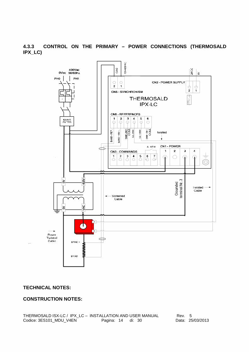
4.3.3 CONTROL ON THE PRIMARY – POWER CONNECTIONS (THERMOSALD IPX_LC)
TECHNICAL NOTES: CONSTRUCTION NOTES:

THERMOSALD ISX-LC / IPX_LC – INSTALLATION AND USER MANUAL Rev. 5 Codice: 3ES101_MDU_V4EN Pagina: 15 di: 30 Data: 25/03/2013
4.3.4 ANALOG CONNECTIONS TO PLC, POTENTIOMETERS, VO LTMETER

THERMOSALD ISX-LC / IPX_LC – INSTALLATION AND USER MANUAL Rev. 5 Codice: 3ES101_MDU_V4EN Pagina: 16 di: 30 Data: 25/03/2013
LIST OF EXCHANGE SIGNALS List of the connections and related PINS of CN1 – POWER TERMINAL BLOCK (MODEL WITH CONTROL ON THE SECONDARY) PIN1 ALTERNATING POWER SUPPLY PIN2 ALTERNATING POWER SUPPLY PIN3 BAND - PIN4 BAND + NOTE1: We recommend you twist the power cables CN1 – POWER TERMINAL BLOCK (MODEL WITH CONT ROL ON THE PRIMARY) PIN1 ALTERNATING POWER SUPPLY INPUT (230VAC) PIN2 PIN3 CONNECT TO 0V OF THE POWER SECONDARY TO CHECK GROUND
CURRENT PIN4 PHASED POWER SUPPLY OUTPUT TO THE PRIMARY OF TRANSFORMER NOTE1: We recommend you twist the power cables NOTE2: Alternating supply of the control circuit wi th the same phase as that of the power circuit CN2 – CONTROL CIRCUIT POWER SUPPLY TERMINAL BLOCK PIN 1 0 Vdc (max absorption: 0.5 A) PIN 2 24 Vdc (max absorption: 0.5 A) NOTE1: 0-24VDC is insulated from the internal power supply and ground
CN3 – COMMAND TERMINAL BLOCK PIN1 0 V PLC COMMON (24 Vdc) (max absorption: 0.1 A) PIN2 PREHEATING COMMAND FROM 24 Vdc PLC (0) (20 mA max) PIN3 SEALING COMMAND FROM 24 Vdc PLC (0) (20 mA max) PIN4 RESET COMMAND FROM 24 Vdc PLC (0) DC (20 mA max) PIN5 CALIBRATION COMMAND FROM 24 Vdc PLC (0) DC (20 mA max) PIN6 SEALING ALARM (N.C. CONTACT) (4 A max) PIN7 SEALING ALARM (N.C. CONTACT) (4 A max) CN5 – PHASE INPUT TERMINAL BLOCK FOR SYNCHRONISM PIN1 230-480 VAC MAIN NET SYNCRONISM (10ma max) PIN2 0 VAC (10ma max)
CN6 – REFERENCE TERMINAL BLOCK
PIN1 REF- BAND REFERENCE (1 mA max) PIN2 REF+ BAND REFERENCE (1 mA max) PIN3 REF0 REFERENCE CABLE SHIELD (do not connect on
the machine side)
PIN4 CT- REFERENCE (500 mA max) twisted cable

THERMOSALD ISX-LC / IPX_LC – INSTALLATION AND USER MANUAL Rev. 5 Codice: 3ES101_MDU_V4EN Pagina: 17 di: 30 Data: 25/03/2013
PIN5 CT+ REFERENCE (500 mA max) twisted cable
PIN6 N.C.
CN7 - POTENTIOMETER CONNECTOR (9 POLES, MALE) PIN1 +4.5V PREHEAT POTENTIOMETER 10Kohm (1 mA max) PIN2 REF+ PREHEAT POTENTIOMETER 10Kohm (1 mA max) PIN3 0V PREHEAT POTENTIOMETER 10Kohm (1 mA max) PIN4 jumper PIN3 and PIN4 (1 mA max) PIN5 PIN6 +4.5V SEALING POTENTIOMETER 10Kohm (1 mA max) PIN7 REF+ SEALING POTENTIOMETER 10Kohm (1 mA max) PIN8 0V SEALING POTENTIOMETER 10Kohm (1 mA max) PIN9 jumper PIN8 and PIN9 (1 mA max) NOTE1: if piloted from analogue PLC output, use PIN 2,PIN3,PIN7,PIN8 and leave PIN4-PIN9 free. NOTE2: REF-, REF+: we recommend you use a shielded twisted pair (e.g. TWINAX IBM cable, our code 3esd0066) CN8 – ANALOGUE OUTPUT TERMINAL BLOCK PIN 1 0 Vdc ANALOGUE (5ma max) PIN 2 0-5 Vdc ANALOGUE REFERENCE OUTPUT (5ma max) PIN 3 ANALOGUE REFERENCE OUTPUT CABLE SHIELD

THERMOSALD ISX-LC / IPX_LC – INSTALLATION AND USER MANUAL Rev. 5 Codice: 3ES101_MDU_V4EN Pagina: 18 di: 30 Data: 25/03/2013
5 COMMISSIONING
5.1 COMMISSIONING WARNINGS -BEFORE STARTING COMMISSIONING carefully read the SAFETY WARNINGS and INSTALLATION WARNINGS in the USER AND INSTALLATION MANUAL this chapter is an integral part of or a copy of it. -The system must have been sized as specified in the installation warnings and built in a workmanlike fashion. -No alarm must be active; in the event of an alarm, the red ALARM LED on, follow the thermoregulator’s suggestions and solve (the alarm number can be identified by counting the impulses of the green balance LED for tens – e.g. 9 impulses = 90 - + the impulses of the red balance LED for units – e.g. 10 impulses = 0 - 8 impulses=8) -For any further information do not hesitate to contact 3E.
5.2 MASTER RESET -The thermoregulator is provided in the MASTER RESE T condition. After every MASTER RESET the parameters return to the default s tatus: in this case the 6 led on the equipment in the right are blinking. To do a MA STER RESET do as follow: Step 1 – verify the preheat and sealing commands must be deactivated (the preheat and seal led must be off on the unit). Step 2 – keep pressed for 6 seconds the RESET + CALIBRATION button on the carter of the thermoregulators; the 4 LEDs on the equipment remain on for 3 seconds. Step 3 – at the end of master reset the 4 LEDS will blink to indicate that a CALIBRATING will be necessari. NOTE: It’s possibile also to do a MASTER RESET from far distance, keeping the external RESET + CALIBRATION command on for 6 seconds.
5.3 CALIBRATION
Step 1 – calibrate only after reading the commissioning warnings. Step 2 – the machine must be at ambient temperature Step 3 – the preheat and sealing commands must be deactivated

THERMOSALD ISX-LC / IPX_LC – INSTALLATION AND USER MANUAL Rev. 5 Codice: 3ES101_MDU_V4EN Pagina: 19 di: 30 Data: 25/03/2013
Step 4 – power on the thermoregulator; if the thermoregulator is in MASTER RESET, without alarm, the 6 leds blinking. Step 5 – in the event of an alarm, red ALARM LED on, follow the thermoregulator’s suggestions and solve. Step 6 – keep the key CAL for 3 seconds and wait: the leds green-red of balancing blinking up to the end after about 30 seconds. Step 7 – set the preheat and sealing temperatures with 2 potentiometers 10Kohm (30 degrees/turn) or with analogue plc outputs (13mV/degree – 13mv x 300°C = 3.9V, 4.2V alarm, range 0-5V). NOTA 1: It’s also possibile to do a CALIBRATING fro m far distance, keeping the external CALIBRATION command on terminal CN3 up for 3 seconds. NOTA 2: if calibration problems occur, perform a MA STER RESET and proceed from step 2.
5.4 ANALOG OUTPUT AND DIAGNOSTIC The thermoregulators is equiped by an analog output 0-5V to output temperature in case of standard functionment, to output alarm number in case of alarm. Case of standard functionment without power (warn33 ): Alarm relay output: closed (CN3/6-CN3/7) Analog output: 0 V Case of standard functionment with power: Alarm relay output: closed (CN3/6-CN3/7) Analog output: temperature 10mv / degree (e.g. 1Volt = 100 degree) Case of alarm (see alarm table, appendix D): Alarm relay: open (CN3/6-CN3/7) Analog output: 1.0 V alarm 78 – equipment not calibrated
1.5 V alarm 46 – no current signal 2.0 V alarm 48 – preheat potentiometer connections 2.0 V alarm 49 – seal potentiometer connections 2.5V alarm 69 – ground current 3.0V alarm 89 – break of 1 of 2 bands in parallel 3.5V alarm 93 – seal command without power 4.0V alarm 94 – reference cable interruption 4.5V alarm 97 – partial short circuit between the bands 4.5V alarm 76 – current too high-circuits in saturation 5.0V alarm non specific: see the blinking of leds green-red alarm.

THERMOSALD ISX-LC / IPX_LC – INSTALLATION AND USER MANUAL Rev. 5 Codice: 3ES101_MDU_V4EN Pagina: 20 di: 30 Data: 25/03/2013
6 MAINTENANCE
6.1 REPLACING THE BAND WITH THE MACHINE COLD (i.e. bars at ambient temperature – scheduled maintenance) 1 – Power off, remove the preheat and sealing commands, let the gripper jaws cool down. 2 – Mount the new bands. 3 – Power on. 4 – Calibrate in order to compensate for any minor mechanical differences of the band (in most cases ambient temperature does not need to be changed in the setting data). 5 – THE MACHINE is ready to work.
6.2 REPLACING THE BAND WITH THE MACHINE HOT(i.e. b ars at operating temperature - quick intervention) 1 – Power off, remove the preheat and sealing commands, let the gripper jaws cool down so the operator can work comfortably. 2 – Mount the new bands. 3 – Power on. 4 – If there are no great mechanical differences in the bands THE MACHINE is ready to work.
6.3 THERMOREGULATOR MAINTENANCE To be scheduled according to the work environment, in any case with routine maintenance intervals should be no longer than 180 days. 1 – Make sure the connection terminals are properly screwed. 2 – Periodically check correct operation of the output safety alarm contact.
6.4 GRIPPER JAWS MAINTENANCE To be scheduled according to the work environment at periodic intervals. 1 – Make sure the feedback reference terminals and power terminals are properly screwed. 2 – Make sure the band’s terminals are highly conductive and do not show any oxidation or bad contacts: if so, service them accurately. 3 – Check the band’s supports in insulating material and Teflon.
THERMOSALD ISX-LC / IPX_LC – INSTALLATION AND USER MANUAL Rev. 5 Codice: 3ES101_MDU_V4EN Pagina: 21 di: 30 Data: 25/03/2013
7 TECHNICAL DATA
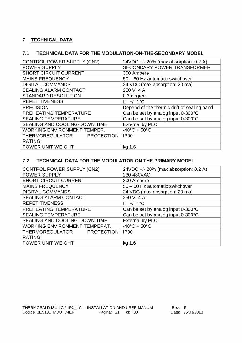
7.1 TECHNICAL DATA FOR THE MODULATION-ON-THE-SECOND ARY MODEL
CONTROL POWER SUPPLY (CN2) 24VDC +/- 20% (max absorption: 0.2 A) POWER SUPPLY SECONDARY POWER TRANSFORMER SHORT CIRCUIT CURRENT 300 Ampere MAINS FREQUENCY 50 – 60 Hz automatic switchover DIGITAL COMMANDS 24 VDC (max absorption: 20 ma) SEALING ALARM CONTACT 250 V 4 A STANDARD RESOLUTION 0.3 degree REPETITIVENESS ≅ +/- 1°C PRECISION Depend of the thermic drift of sealing band PREHEATING TEMPERATURE Can be set by analog input 0-300°C SEALING TEMPERATURE Can be set by analog input 0-300°C SEALING AND COOLING-DOWN TIME External by PLC WORKING ENVIRONMENT TEMPER. -40°C + 50°C THERMOREGULATOR PROTECTION RATING
IP00
POWER UNIT WEIGHT kg 1.6
7.2 TECHNICAL DATA FOR THE MODULATION ON THE PRIMAR Y MODEL
CONTROL POWER SUPPLY (CN2) 24VDC +/- 20% (max absorption: 0.2 A) POWER SUPPLY 230-480VAC SHORT CIRCUIT CURRENT 300 Ampere MAINS FREQUENCY 50 – 60 Hz automatic switchover DIGITAL COMMANDS 24 VDC (max absorption: 20 ma) SEALING ALARM CONTACT 250 V 4 A REPETITIVENESS ≅ +/- 1°C PREHEATING TEMPERATURE Can be set by analog input 0-300°C SEALING TEMPERATURE Can be set by analog input 0-300°C SEALING AND COOLING-DOWN TIME External by PLC WORKING ENVIRONMENT TEMPERAT. -40°C + 50°C THERMOREGULATOR PROTECTION RATING
IP00
POWER UNIT WEIGHT kg 1.6

THERMOSALD ISX-LC / IPX_LC – INSTALLATION AND USER MANUAL Rev. 5 Codice: 3ES101_MDU_V4EN Pagina: 22 di: 30 Data: 25/03/2013
8 ORDERING DATA
8.1 CODES FOR ORDERING
MODELS Description CODICE DI ORDINAZIONE
THERMOSALD ISX-LC-60A
Impulse thermoregulator - low cost SECONDARY - 60 Ampere
3ES101S6
THERMOSALD ISX-LC-90A
Impulse thermoregulator - low cost SECONDARY - 90 Ampere
3ES101S9
THERMOSALD IPX-LC-400V
Impulse thermoregulator - low cost PRIMARY – 400/480 Volts
3ES101P4
Opzione High Volt Voltage on band: 100-140V(+0 Levels) Z=HIVL Opzione Low Volt Voltage on band: 3-10V(+0 Levels) Z=LOVL TA Amperometric transformer 3ES080A002 Power transformer Contact technical department for sizing Bands, Belts and sealing wires
Bands, belts and sealing wires with different profiles, in metres, specifically designed, copper-plated, Teflon-coated
8.2 SUGGESTIONS FOR CHOOSING THE MODEL - Use model I=60A for a total band cross-section <= 2sq.mm - Use model I=90A for a total band cross-section > 2sq.mm - Use model HV for transformer V voltage > 100Vac) - Use model LV for transformer V voltage < 10Vac
Installation and user manual in ITALIAN 3ES101_MDU_V4IT Installation and user manual in ENGLISH 3ES101_MDU_V4EN Installation and user manual in FRENCH 3ES101_MDU_V3FR Installation and user manual in GERMAN 3ES101_MDU_V3DE Installation and user manual in SPANISH 3ES101_MDU_V3SP

THERMOSALD ISX-LC / IPX_LC – INSTALLATION AND USER MANUAL Rev. 5 Codice: 3ES101_MDU_V4EN Pagina: 23 di: 30 Data: 25/03/2013
APPENDIX A – SEALING CYCLE NOTE - The sealing cycle suggested is given by way of example only and is not to be considered as a binding usage diagram. Experience shows that the timing must be changed according to the specific application, i.e. of the materials, dimensions, times, etc. For further information please contact our technical department.
PRE-HEATINGSIGNAL (IN THERMOSALD)
SEALING SIGNAL
(IN THERMOSALD)
closed FILM GRIPPER JAWS
open
closed BAND SEALERS
open
COOLING
FILM FEED

THERMOSALD ISX-LC / IPX_LC – INSTALLATION AND USER MANUAL Rev. 5 Codice: 3ES101_MDU_V4EN Pagina: 24 di: 30 Data: 25/03/2013
APPENDIX D – LIST OF ALARMS AND MESSAGES (CAUSES – REMEDIES) NOTE – To reset any alarm raise the RESET command from the interface and press the RESET / MODE button NOTE – When in the alarm condition the RED LED lights up; the alarm number can be deducted from the green and red LED blinking: ALARM NO.=NO. OF GREEN LED IMPULSES x 10 + NO. OF R ED LED IMPULSES NOTE – When in the warning condition the YELLOW LED lights up; the warning number can be deducted from the green and red LED blinking: WARNING NO.=NO. OF GREEN LED IMPULSES x 10 + NO. OF RED LED IMPULSES ALARM DESCRIPTION REMEDY FAULT A thermoregulator completely OFF plus
display completely OFF Check the power supply; power supply unit faulty; contact the supplier
F001 EEPROM WRITING INTERRUPTED Switch the equipment OFF and then ON; then contact the supplier
F002 EEPROM WRITING WITH PREVIOUS OPERATION IN PROGRESS
Switch the equipment OFF and then ON; then contact the supplier
F003 EEPROM WRITING WITH FAULTY EEPROM
Switch the equipment OFF and then ON; then contact the supplier
F004 INDEX CORRUPTED SOFWARE STRUCTURE READ-WRITE EEPROM
Switch the equipment OFF and then ON; then contact the supplier
F007 A/D CONVERTER –CONVERTER WRITING ERROR
Switch the equipment OFF and then ON; then contact the supplier
F008 INTERNAL I2C-X TRANSMISSION Switch the equipment OFF and then ON
F009 DO NOT USE F010 A/D CONVERTER –CHANNEL
SELECTION ERROR Switch the equipment OFF and then ON; then contact the supplier
F032 WARNING WAITING POWER DURING CALIBRATING
Switch power on
F033 WARNING: no VOLTAGE IN THE POWER TRANSFORMER OR BAND NOT CONNECTED
Check the CN1/L1,L2 power supply, the power transformer circuit, check connection of the power cables on the band.
F034 DO NOT USE F038 WARNING – Waiting for machine to cool To perform a calibration

THERMOSALD ISX-LC / IPX_LC – INSTALLATION AND USER MANUAL Rev. 5 Codice: 3ES101_MDU_V4EN Pagina: 25 di: 30 Data: 25/03/2013
down upon calibration request procedure it is necessary to wait until the sealing bar reaches a stable temperature.
F041 DEFAULT HARDWARE DATA RAM CONTROL REAL TIME CORRUPTED
Switch the equipment OFF and then ON; then contact the supplier
F039 WARNING – Sealing out of range Low power for the first sealing F046 NO CURRENT SIGNAL Check CT connection and band
power cable connections F047 CT SIGNAL REVERSED Reverse CT connection F048 PREHEAT POTENTIOMETER NOT
CONNECTED OR CABLES INTERRUPTED
Check preheat potentiometer connections
F049 SEALING POTENTIOMETER NOT CONNECTED OR CABLES INTERRUPTED
Check sealing potentiometer connections
F051 WIPER-IGROSS Switch the equipment OFF and then ON; if the problem persists, contact the supplier
F052 WIPER-VGROSS Switch the equipment OFF and then ON; if the problem persists, contact the supplier
F053 WIPER-IFINE Switch the equipment OFF and then ON; if the problem persists, contact the supplier
F054 WIPER-VFINE Switch the equipment OFF and then ON; if the problem persists, contact the supplier
F059 PERIOD OF MAIN NET OUT OF RANGE (from V4.2)
Switch the equipment OFF and then ON
F060 RESET WITH CALIBRATION IN PROGRESS
Repeat calibration
F061 IGROSS BALANCE NOT SUCCESSFUL Repeat calibration F062 VGROSS BALANCE NOT SUCCESSFUL Verify if Band +/- Ref connected
together; Verify if voltage power transf. is right; Repeat calibration
F063 IFINE BALANCE NOT SUCCESSFUL Repeat calibration F064 VFINE BALANCE NOT SUCCESSFUL Repeat calibration F065 SUPERFINE BALANCE NOT
SUCCESSFUL Repeat calibration
F066 WARNING: SYNCHRONISM DUE TO MAINS FREQUENCY OSCILLATION - MAINS SYNCHRONISM INTERFERENCE
Verify connection power transformer and Main Frequency
F069 GROUND CURRENT Check the band on the machine or the band connection, probably grounded. NOTE: the thermoregulator is

THERMOSALD ISX-LC / IPX_LC – INSTALLATION AND USER MANUAL Rev. 5 Codice: 3ES101_MDU_V4EN Pagina: 26 di: 30 Data: 25/03/2013
grounded via a ground screw, the band wires must therefore be disconnected before checking using an electrical instrument.
F071 HARDWARE FAULT – ANALOGUE +/–15V BREAKAGE
Reset the equipment; if the problem persists, contact the supplier
F072 HARDWARE FAULT – ANALOGUE +/-5V BREAKAGE
Reset the equipment; if the problem persists, contact the supplier
F073 HARDWARE FAULT – REFERENCE +5V BREAKAGE
Reset the equipment; if the problem persists, contact the supplier
F074 INTERNAL TEMPERATURE PROBE – HEAT SINK TEMPERATURE TOO HIGH
Switch the equipment OFF; if the problem persists, contact the supplier
F075 WARNING INTERRUPT FIRE BLOCK Verify connection power transformer and Main Frequency
F076 IREAD TOO HIGH Check if there is a short circuit on the bands
F077 MANUAL CMD FROM THE PANEL NOT ACTIVE DUE TO PREHEAT OR SEALING FROM OUTSIDE
Remove the preheat and sealing before giving the command
F078 EQUIPMENT NOT CALIBRATED Perform the automatic calibration procedure without giving the preheat or sealing command
F079 EMERGENCY CIRCUIT FAULT Check the power contactor, check the emergency chain
F080 BACK_FIRE TIMER CONTROL Reset the equipment; if the problem persists, contact the supplier
F081 HARDWARE FAULT – CHECKSUM ALARM READING EEPROM
Inconsistent data have been found on eeprom, proceed carefully Press RESET/MODE, check MACHINE DATA, SETTING DATA and TEMPERATURES set. Contact the supplier
F082 phase displacement between power (CN1) and control power supply (CN2) – only primary model
Make sure the two power supplies are in phase (pay attention to the phase-phase/phase-neutral phase displacement)
F083 REFERENCE CABLES REVERSED WITH RESPECT TO THE POWER CABLES
Check the reversed reference cables: CN1/3 corresponds to CN6/1 CN1/4 corresponds to CN6/2
THERMOSALD ISX-LC / IPX_LC – INSTALLATION AND USER MANUAL Rev. 5 Codice: 3ES101_MDU_V4EN Pagina: 27 di: 30 Data: 25/03/2013
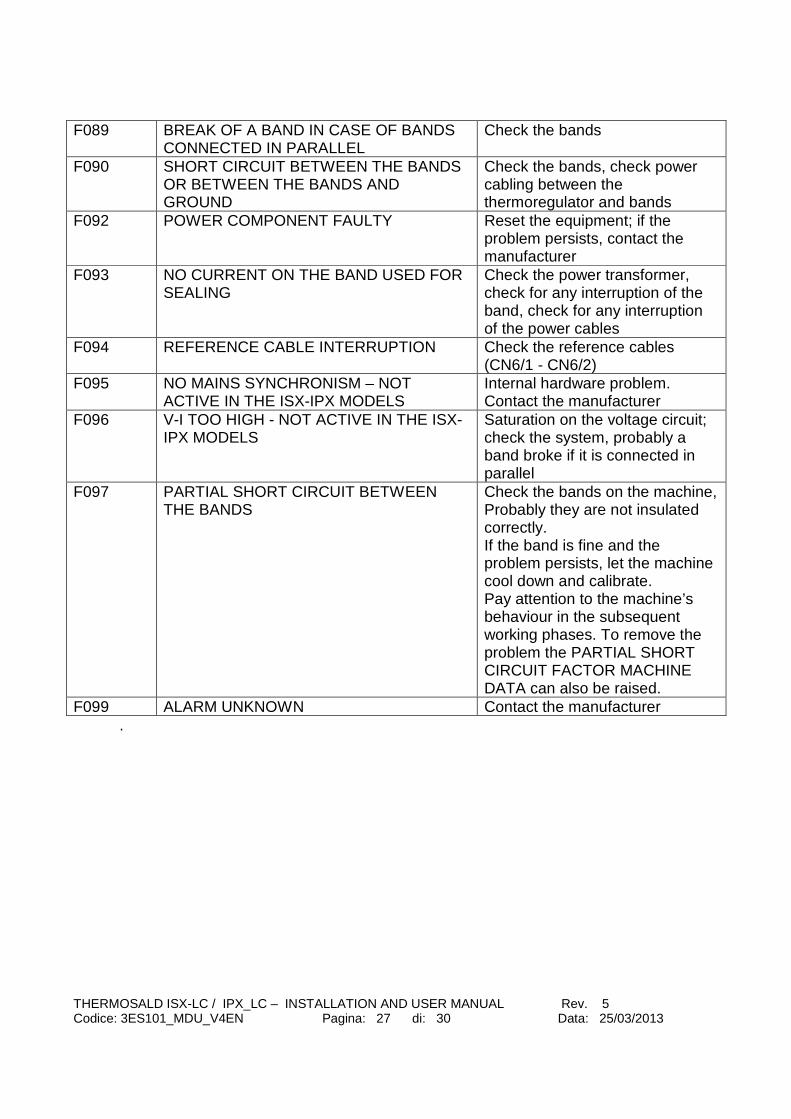
F089 BREAK OF A BAND IN CASE OF BANDS CONNECTED IN PARALLEL
Check the bands
F090 SHORT CIRCUIT BETWEEN THE BANDS OR BETWEEN THE BANDS AND GROUND
Check the bands, check power cabling between the thermoregulator and bands
F092 POWER COMPONENT FAULTY Reset the equipment; if the problem persists, contact the manufacturer
F093 NO CURRENT ON THE BAND USED FOR SEALING
Check the power transformer, check for any interruption of the band, check for any interruption of the power cables
F094 REFERENCE CABLE INTERRUPTION Check the reference cables (CN6/1 - CN6/2)
F095 NO MAINS SYNCHRONISM – NOT ACTIVE IN THE ISX-IPX MODELS
Internal hardware problem. Contact the manufacturer
F096 V-I TOO HIGH - NOT ACTIVE IN THE ISX-IPX MODELS
Saturation on the voltage circuit; check the system, probably a band broke if it is connected in parallel
F097 PARTIAL SHORT CIRCUIT BETWEEN THE BANDS
Check the bands on the machine, Probably they are not insulated correctly. If the band is fine and the problem persists, let the machine cool down and calibrate. Pay attention to the machine’s behaviour in the subsequent working phases. To remove the problem the PARTIAL SHORT CIRCUIT FACTOR MACHINE DATA can also be raised.
F099 ALARM UNKNOWN Contact the manufacturer .

THERMOSALD ISX-LC / IPX_LC – INSTALLATION AND USER MANUAL Rev. 5 Codice: 3ES101_MDU_V4EN Pagina: 28 di: 30 Data: 25/03/2013
APPENDIX E – MECHANICAL DIMENSIONS THERMOREGULATOR DIMENSIONS 100 x 120 (VIEW FROM TOP) HEIGHT = 135mm DRILLING TEMPLATE 3 HOLES Dia.=4.5 mm 120 [mm] 95 [mm] 82[mm] 20 [mm] 100 [mm]

THERMOSALD ISX-LC / IPX_LC – INSTALLATION AND USER MANUAL Rev. 5 Codice: 3ES101_MDU_V4EN Pagina: 29 di: 30 Data: 25/03/2013
APPENDIX F – TABLE OF BANDS TABLE OF THE CHAMFERED BANDS IN SPECIAL ALLOY (Band extension 50PPM, 0.05mm/metre per degree – 5m m/metre per 100 degrees)
Band Width (mm)
Band Thickness (mm)
Specific Resistance R0 ΩΩΩΩ / m
1.5 0.3 1.67 2 0.25 1.59 3 0.1 2.95 3 0.15 1.95 3 0.2 1.50 3 0.25 1.27 4 0.15 1.40 4 0.25 0.96 5 0.2 0.8 5 0.25 0.69 6 0.1 1.6 6 0.2 0.72 8 0.1 1.2 8 0.2 0.51
TABLE OF THE T-SHAPE BANDS IN SPECIAL ALLOY
Band Width (mm)
Band Thickness (mm)
Specific Resistance R0 ΩΩΩΩ / m
2.8 0.3 0.9 4 0.3 0.6
TABLE OF THE BEADED ELEMENT BANDS IN SPECIAL ALLOY
Band Width (mm)
Band Thickness (mm)
Specific Resistance R0 ΩΩΩΩ / m
4 0.15 1.4 4 0.25 0.9 6 0.15 0.99 6 0.25 0.6
TABLE OF THE CONCAVE BANDS IN SPECIAL ALLOY
Band Width (mm)
Band Thickness (mm)
Specific Resistance R0 ΩΩΩΩ / m
2.8 0.3 0.9

THERMOSALD ISX-LC / IPX_LC – INSTALLATION AND USER MANUAL Rev. 5 Codice: 3ES101_MDU_V4EN Pagina: 30 di: 30 Data: 25/03/2013
APPENDIX G – COMMISSIONING SHEET SEALING BANDS WIDTH X THICKNESS SEALING BANDS TOTAL LENGTH USEFULL LENGTH (TOTAL - COPPER TRANSFORMER POWER [VA] TRANSFORMER PRIMARY VOLTAGE [V] TRANSFORMER SECONDARY VOLT [V] THERMOSALD ISX / IPX MODEL ORDERED OPTIONS
PREHEAT TEMPERATURE [°C] SEALING TEMPERATURE [°C] SEALING TIME [Sec.]