SPAREPARTSCATALOGUE CATALOGO PEZZI Dl RICAMBIO … 171, 173, 174.pdf · CATALOGO PEZZI Dl RICAMBIO...
45
Rimoldi' SPARE PARTS CATALOGUE CATALOGO PEZZI Dl RICAMBIO CATALOGUE RECHARGES ERSATZTEILEUSTE (fm» 171 173 174 n. 108 From the library of: Superior Sewing Machine & Supply LLC
Transcript of SPAREPARTSCATALOGUE CATALOGO PEZZI Dl RICAMBIO … 171, 173, 174.pdf · CATALOGO PEZZI Dl RICAMBIO...
Rimoldi'SPARE PARTS CATALOGUE
CATALOGO PEZZI Dl RICAMBIO
CATALOGUE RECHARGES
ERSATZTEILEUSTE
(fm»
171
173
174
n. 108From the library of: Superior Sewing Machine & Supply LLC
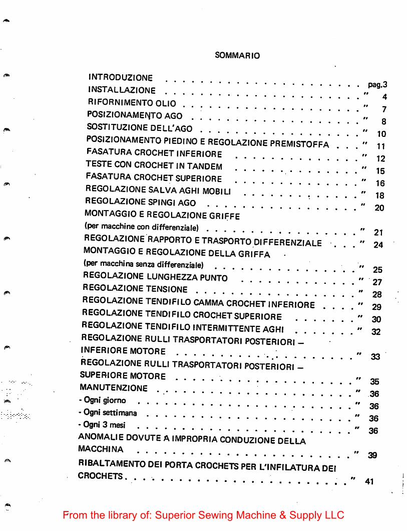
SOMMARIO
INTR0DU2I0NE
installazionerifornimento OLIO „ ^P0SI2I0NAMEIV|T0 AGO . „S0STITU2I0NE DELL'AGO " iqP0SI2I0NAMENT0 PIEDINO EREG0LA2I0NE PREMISTOFFA . . "11fasatura crochet INFERIORE "12TESTE CON CROCHET IN TANDEM „fasatura CROCHET SUPERIOREREG0LA2I0NE SALVA AGHI MOBILI ' „ „REG0LA2I0NE SPINGI AGO •.MONTAGGIO E REG0LA2I0NE GRIFFE(per macchine con differenziale) "21REGOLA2IONERAPPORTOETRASPORTODIFFERENZIALE . . . " 24MONTAGGIO EREG0LA2I0NE DELLAGRIFFA •(per macchina senza differenziale) "25REG0LA2I0NE LUNGHE22A PUNTOREG0LA2I0NE TENSIONE "28REG0LA2I0NETENDIFIL0CAMMA CROCHET INFERIORE ... "29REGOLAZIONETENDIFILO CROCHET SUPERIORE ...... . " 30REGOLAZIONETENDIFILOINTERMITTENTEAGHI .... . . . " 32REGOLAZIONE RULLI TRASPORTATORI POSTERIORI —INFERIORE MOTORE ; "33REGOLAZIONE RULLI TRASPORTATORI POSTERIORI -SUPERIORE MOTORE "35MANUTENZIONE "36-Ogni giorno ' " 36- Ogni settimana " oc
_ . _ . 36- Ogni 3 mesi » oc
06ANOMALIE DOVUTE AIMPROPRIA CONDUZIONE DELLAmacchina „ ggRIBALTAMENTO DEI PORTA CROCHETS PER L'INFILATURA DEIcrochets. .... «
41
From the library of: Superior Sewing Machine & Supply LLC
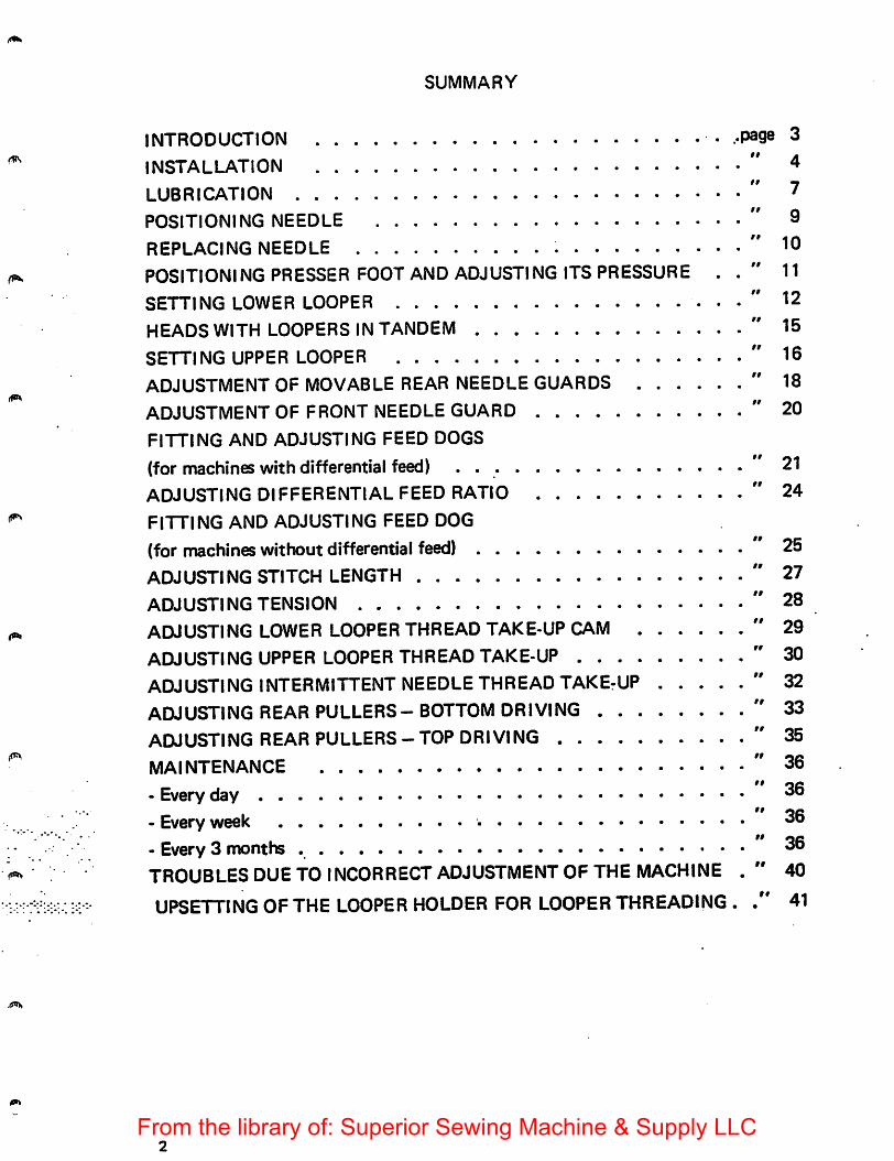
SUMMARY
INTRODUCTION
INSTALLATION
LUBRICATION
POSITIONING NEEDLE
REPLACING NEEDLE
POSITIONING PRESSER FOOT AND ADJUSTING ITS PRESSURE .
SETTING LOWER LOOPER
HEADS WITH LOOPERS IN TANDEM
SETTING UPPER LOOPER
ADJUSTMENT OF MOVABLE REAR NEEDLE GUARDS
ADJUSTMENT OF FRONT NEEDLE GUARD
FITTING AND ADJUSTING FEED DOGS
(for machines with differential feed) .
ADJUSTING DIFFERENTIAL FEED RATIO
FITTING AND ADJUSTING FEED DOG
(for machines wit tout differential feed)ADJUSTING STITCH LENGTH
ADJUSTING TENSION
ADJUSTING LOWER LOOPER THREAD TAKE-UP CAM
ADJUSTING UPPER LOOPER THREAD TAKE-UPADJUSTING INTERMITTENT NEEDLE THREAD TAKErUP ....
ADJUSTING REAR PULLERS - BOTTOM DRIVING
ADJUSTING REAR PULLERS-TOP DRIVING
MAINTENANCE
- Every day
- Every week
- Every 3 months
TROUBLES DUE TO INCORRECT ADJUSTMENT OF THE MACHINE
UPSETTING OF THE LOOPER HOLDER FOR LOOPER THREADING .
page 3
" 4
" 7
" 9
" 10
' 11
' 12
' 15
' 16
' 18
' 20
" 21
" 24
25
27
28
29
30
32
33
35
36
36
36
36
40
41
From the library of: Superior Sewing Machine & Supply LLC
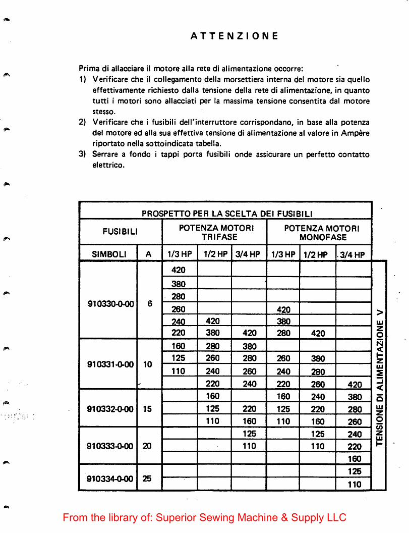
ATTENZIONE
Prima di allacciare ii motore alia rate di alimentazione occorre:
1) Verificare che il collegamento della morsettiera interna del motore sia quelloeffettivamente richiesto dalla tensione della rete di alimentazione, in quanto
tutti i motori sono allacciati per la massima tensione consentita dal motore
stesso.
2) Verificare che i fusibili delTinterruttore corrispondano, in base alia potenzadel motore ed alia sua effettiva tensione di alimentazione al valore in Ampere
riportato nella sottoindicata tabella.3) Serrare a fondo i tappi porta fusibili onde assicurare un perfetto contatto
elettrico.
PROSPETTO PER LA SCELTA DEI FUSIBILI•
FUSIBILI POTENZA MOTORITRIFASE
POTENZA MOTORIMONOFASE
SIMBOLI A 1/3 HP 1/2 HP 3/4 HP 1/3 HP 1/2 HP .3/4 HP
420
380
910330-0-00280
6260 420 >
240 420 380 UJ
220 380 420 280 420zo
160 280 380 N<
910331-0-00 10125 260 280 260 380
HZ
110 240 260 240 280UJ
S
220 240 220 260 420-j
160 160 240 380 o
910332-(M)0 15 125 220 125 220 280 UJ2
110 160 110 160 260 O(/)zUJ1-
125 125 240
910333-000 20 110 110 220
160
910334-0-00 25125
110
From the library of: Superior Sewing Machine & Supply LLC
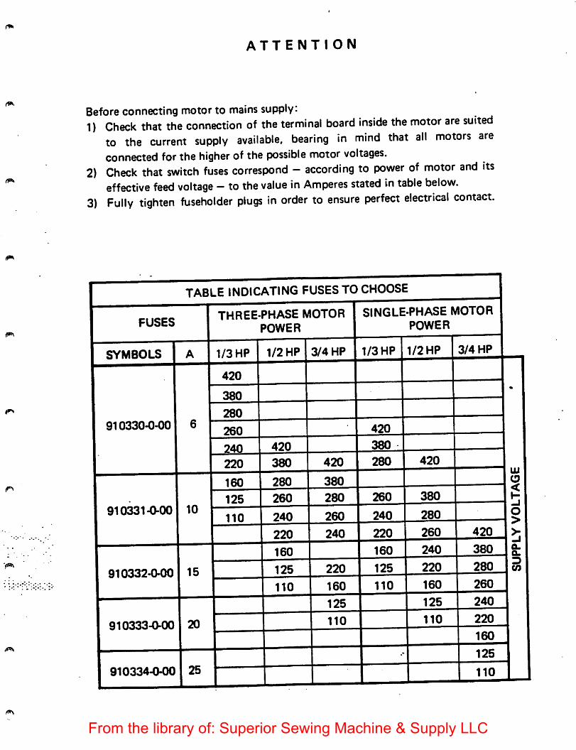
ATTENTION
Before connecting motor to mains supply:1) Check that the connection of the terminal board inside the motor are suited
to the current supply available, bearing in mind that all motors areconnected for the higher of the possible motor voltages.
2) Check that switch fuses correspond - according to power of motor and itseffective feed voltage - to the value in Amperes stated in table below.
3) Fully tighten fuseholder plugs in order to ensure perfect electrical contact.
SYMBOLS
910330-0-00
910331-0-00
910332-0-00
910333-0-00
910334-0-00
TABLE INDICATING FUSESTO
THREE-PHASE MOTORPOWER
1/3 HP
420
1/2 HP 3/4 HP
CHOOSE
SINGLE-PHASE MOTORPOWER
1/3 HP 1/2 HP 3/4 HP
From the library of: Superior Sewing Machine & Supply LLC
INTRODUZIONE
Abbiamo raccolto nel presente libretto alcune note relative all'installazione, messa apunto e manutenzione delle macchine Rimoldi Serie "BASE CILINDRICA ELI SERA" che riteniamo possano esserVi utili per megjio conoscere e piuconvenientemente usare il nostro prodotto.Queste macchine giungono aVoi dopo scrupolosi controlli erigorosi collaudi che cipermettono di garantirne la durata e I'efficienza, ma Vi ricordiamo che questedipendono notevolmente dall'uso e dalla manutenzione che saranno riservate allemacchine, pertanto prima deirimpiego, Vi consigliamo nel Vostro interesse diconsultare attentamente questo fascicolo e seguire con cura le istruzioni in essocontenute.
* * *
INTRODUCTION
This booklet contains some notes on the installation, operation and maintenance ofRimoldi "CYLINDER BED" which should be useful to owners and should helpthem to become familiar with the machine and derive the best use from it.Before despatch, the machine was carefully checked and thoroughly tested toensure its durability and efficiency; it must, however, be remembered that thesedepend very much on how the machine is operated and maintained, and it istherefore in the interest of the owner to read this booklet carefully and follow theinstructions given in it.
From the library of: Superior Sewing Machine & Supply LLC
INSTALLAZIONE
Per rinstallazione della testa ed il suo collegamento con il motore (gia montato sulbancale), mediante cinghia di trasmisslone, procedere come segue:1. premere con forza i quattro tamponi ammortizzatori sugli appositi perni della
piastra di sostegno.
2. piazzare la macchina sul bancale, centrando le sedi coniche ricavate nelleorecchiettedella bacinella sul quattro tamponi ammortizzatori 2 (fig. 1).
3. collegare il tirante 1 (fig. 1) alia leva alza piedino della macchina4. collegare il volantino della macchina alia puleggia del motore con I'apposita
cinghia di trasmissione sezione 10x6 (fig. 2) secondo lo schema di collegamento(fig. 3).
5. registrare la tensione della cinghia agendo sullo snodo attacco motore, in mododa non consentire slittamenti, rha avendo cura di non tenderia eccessivamenteonde evitare sovraccarichi sugli alberi delle pulegge e non compromettere ladurata della cinghia stessa. Si ha la giusta tensione quando, premendo con lamano al centro del tratto indicato in fig. 3, si verifica una freccia, cioe uncedimento della cinghia, di 10-15 mm.
6. livellare la testa della macchina affinche la cinghia si trovi sul piano normale agliassi delle pulegge e al centro delle loro gole. Per I'operazione di livellamento,agire sui perni sostegno testa 3 (fig. 1), avendo cura di bloccare successivamentegli appositi dadi.
« ♦ ♦
INSTALLATION
Installation of the machine headand connection to the motor (already mounted onthe stand) by means of driving belt is carriedout as follows:1. Press the four shock absorbersdown hard on the pinson the support plate.2. Place the machine on the stand, centeringthe conical housings of the sump lugs
on the four shock absorbers 2 (fig. 1).3. Connect stay-rod 1 (fig. 1) to machine presser foot lifter lever.4. Connect machine handwheel to motor pulley with 10x6 section driving belt
(fig, 2) as shown in sketch (fig. 3).5. Adjust the belt tisnsion by moving the motor coupling articulated joint so that
the belt cannot slip, but taking care not to make it over-taut, to avoidoverloading the pulley shafts and shortening the life of the belt. The tension iscorrect when, putting manual pressure on the cisntre of the part indicated in fig.3,the belt yields about 10-15 mm. (3/8"-9/16").
6. Level the machine head so that the belt is perpendicular to the pulley axes andthus centered in their races. For the levelling operation, adjust the headsupportpins 3 (fig. 1), making sure to lock them again afterwards with the relative nuts.
From the library of: Superior Sewing Machine & Supply LLC
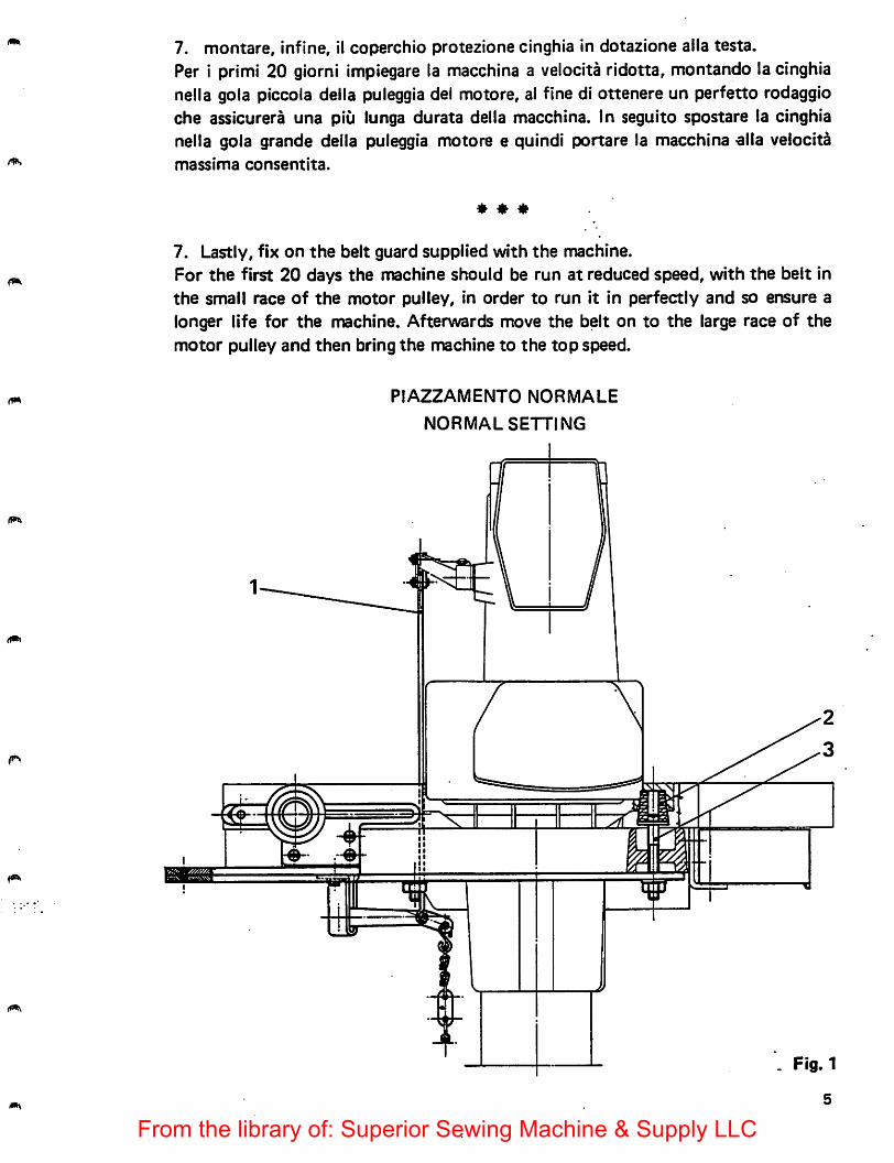
7. montare, infine, il coperchio protezione cinghia in dotazione aila testa.Per i primi 20 giorni impiegare la macchina a velocita rldotta, montando la cinghianella gola piccola della puleggia del motore, al fine di ottenere un perfetto rodaggioche assicurera una piii lunga durata della macchina. In seguito spostare la cinghianella gola grande della puleggia motore e quindi portare la macchina ella velocitamassima consentita.
7. Lastly, fix on the belt guard supplied with the machine.For the first 20 days the machine should be run at reduced speed, with the belt inthe small race of the motor pulley, in order to run it in perfectly and so ensure alonger life for the machine. Afterwards move the belt on to the large race of themotor pulley and then bring the machine to the top speed.
PIAZZAMENTO NORMALE
NORMAL SETTING
Fig.1
5
From the library of: Superior Sewing Machine & Supply LLC
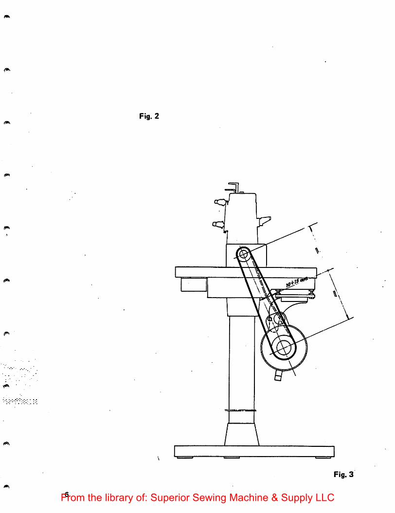
Fig. 2
I V
Fig. 3
From the library of: Superior Sewing Machine & Supply LLC
RIFORNIMENTO OLIO
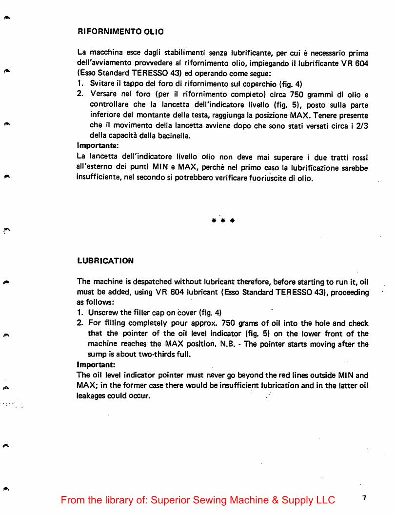
La macchina esce dagli stabilimenti senza lubrificante, per cui e necessario primadeiravviamento provvedere ai rifornimento olio, impiegando 11 lubrificante VR 604(Esso Standard TERESSO 43) ed operando come segue:1. Svitare il tappo del foro di rifornimento sul coperchio (fig. 4)2. Versare nel foro (per il rifornimento completo) circa 750 grammi di olio e
controllare che la lancetta dell'lndicatore livello (fig. 5), posto sulla parteinferiore del montante della testa, raggiunga la posizione MAX. Tenere presenteche il movimento della lancetta avviene dopo che sono stati versati circa i 2/3della capacita della bacinella.
Importante:
La lancetta dell'indicatore livello olio non deve mai superare i due tratti rossiall'esterno del punti MIN e MAX, perche nel primo caso la lubrificazione sarebbeinsufficiente, nel secondo si potrebbero verificare fuoriuscite di olio.
* * *
LUBRICATION
The machine is despatched without lubricant therefore, before starting to run it, oilmust be added, using VR 604 lubricant (Esso Standard TERESSO 43), proceedingas follows:
1. Unscrew the filler cap on cover (fig. 4)2. For filling completely pour approx. 760 grams of oil into the hole and check
that the pointer of the oil level indicator (fig. 5) on the lower front of themachine reaches the MAX position. N.B. - The pointer starts moving after thesump is about two-thirds full.
important:
The oil level indicator pointer must never go beyond the red lines outside MIN andMAX; in the former case there would be insufficient lubrication and in the latter oil
leakages could occur.
From the library of: Superior Sewing Machine & Supply LLC
£
Fig. 5
POSIZIONAMENTO AGHI
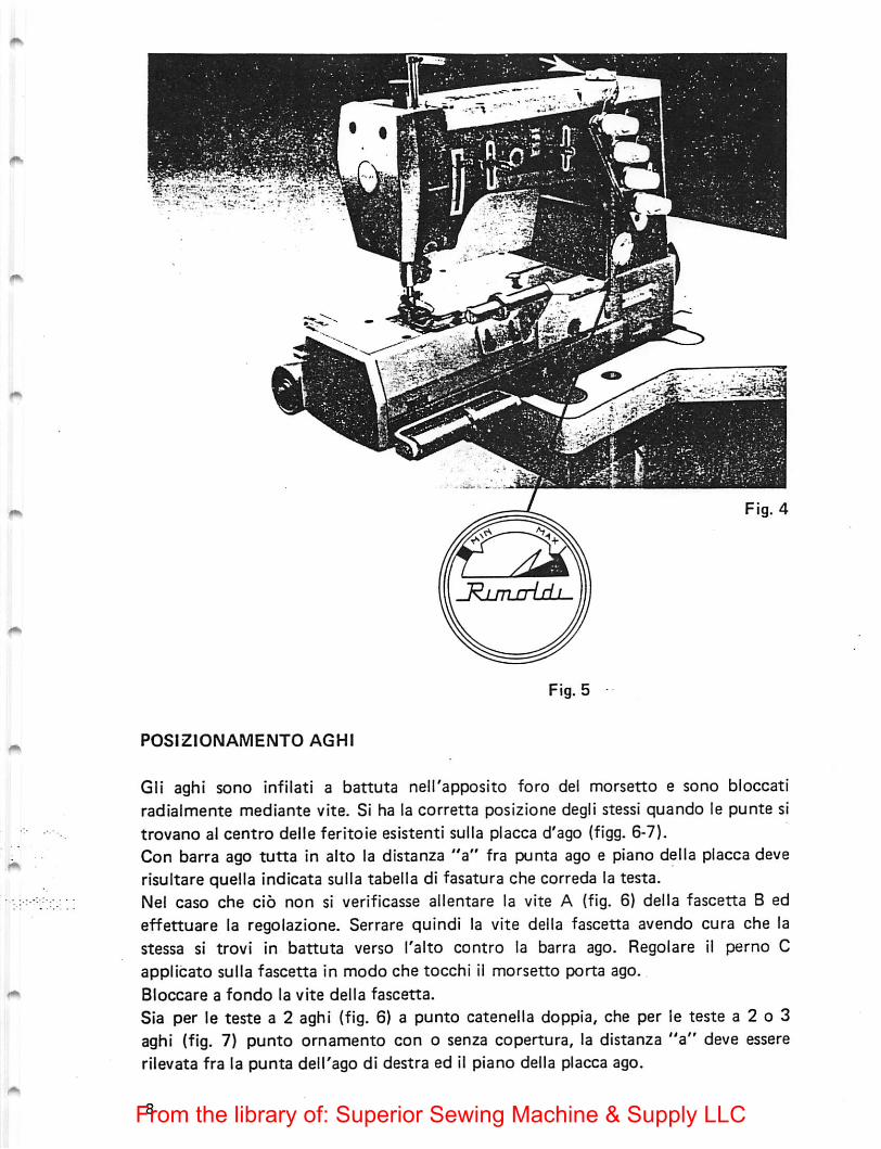
Gli aghi sono infilati a battuta nell'apposito foro del morsetto e sono bloccatiradialmente mediante vite. Si ha la corretta posizione degli stessi quando le punte sitrovano al centro delle feritoie esistenti sulla placca d'ago (flgg. 6-7).Con barra ago tutta in alto la distanza "a" fra punta ago e piano della placca deverisultare quella indicata sulla tabella di fasatura che correda la testa.Nel caso che cio non si verificasse allentare la vite A (fig. 6} delta fascetta B ed
effettuare la regolazione. Serrare quindi la vite della fascetta avendo cura che lastessa si trovi in battuta verso I'alto contro la barra ago. Regolare il perno Capplicato sulla fascetta in modo che tocchi il morsetto porta ago.
Bloccare a fondo la vite della fascetta.
Sia per le teste a 2 aghi (fig. 6) a punto catenella doppia, che per le teste a 2 o 3aghi (fig. 7) punto ornamento con o senza copertura, la distanza "a" deve essererilevata fra la punta delTago di destra ed 11 piano della placca ago.
From the library of: Superior Sewing Machine & Supply LLC
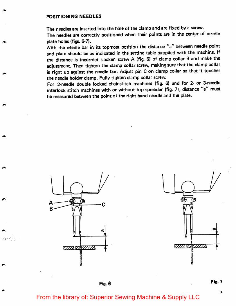
POSITIONING NEEDLES
The needles are inserted into the hole of the clamp and are fixed by a screw.The needles are correctly positioned when their points are in the center of needleplate holes (figs. 6-7).With the needle bar in its topmost position the distance "a" between needle pointand plate should be as indicated in the setting table supplied with the machine. Ifthe distance is incorrect slacken screw A (fig. 6) of clamp collar B and make theadjustment. Then tighten the clamp collar screw, making sure that the clamp collaris right up against the needle bar. Adjust pin Con clamp collar so that it touchesthe needle holder clamp. Fully tighten clamp collar screw.For 2-needle double locked chainstitch machines (fig. 6) and for 2- or 3-needleinterlock stitch machines with or without top spreader (fig. 7), distance "a" mustbe measured between the point of the right hand needle and the plate.
Fig. 6 Fig. 7
y
From the library of: Superior Sewing Machine & Supply LLC
SOSTITUZIONE AGO
Spegnere ii motore ed assicurarsi, premendo ii pedale, che la macchina siaassoiutamente ferma.
Ruotare normalmente ii voiantino portando la barra ago tutta in alto. Allentare iavite serra ago A (fig. 9), estrarre I'ago e sostituirlo con ii nuovo. Tenere presente cheI'incavo passaggio crochet deve essere rivolto verso i'interno deila macchina.
Servendosi della pinza in dotazione, accertarsi che I'ago appoggi sul fondo foro.Avvitare, senza eccedere nel bloccaggio, la vite serra ago, avendo cura di non variare
I'orientamento dell'ago.
♦ « ♦
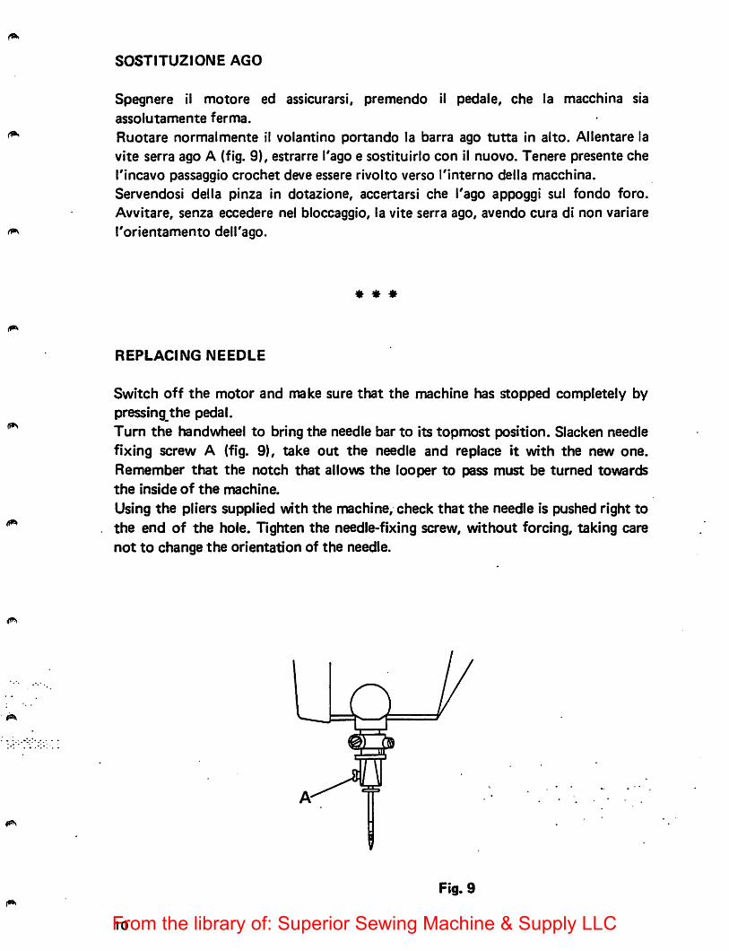
REPLACING NEEDLE
Switch off the motor and make sure that the machine has stopped completely bypressing the pedal.Turn the handwheel to bring the needle bar to its topmost position. Slacken needlefixing screw A (fig. 9|, take out the needle and replace it with the new one.Remember that the notch that allows the looper to pass must be turned towardsthe inside of the machine.
Using the pliers supplied with the machine, check that the needle is pushed right tothe end of the hole. Tighten the needle-fixing screw, without forcing, taking carenot to change the orientation of the needle.
Fig. 9
10From the library of: Superior Sewing Machine & Supply LLC
POSIZIONAMENTO PIEDINO E REGOLAZIONE PREMISTOFFA (fig. 10)
Si ha la corretta posizione del piedino quando Tago passa al centro dell'appositaferitoia del piedino. Allentando la vite C che blocca il piedino alia barra e possibileeffettuare il centraggio.
Tenere presente che con piedino sollevato di circa 4,5 mm. dalla placca d'ago, ipiattelli delle tensioni devono essere aperti. In caso contrario allentare la vite A espostare di quanto necessario la leva B. Per regolare la pressione che il piedino deveesercitare sul tessuto, avvitare o svitare secondo il necessario, il pomolo D.
* * *
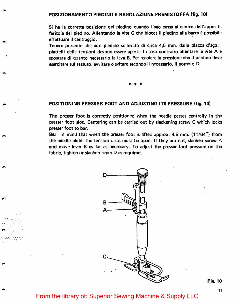
POSITIONING PRESSER FOOT AND ADJUSTING ITS PRESSURE (fig. 10)
The presser foot is correctly positioned when the needle passes centrally in thepresser foot slot. Centering can be carried out by slackening screw C which lockspresser foot to bar.Bear in mind that when the presser foot is lifted approx. 4.5 mm. (11/64") fromthe needle plate, the tension discs must be open. If they are not, slacken screw A
and move lever B as far as necessary. To adjust the presser foot pressure on thefabric, tighten or slacken knob D as required.
Fig. 10
11
From the library of: Superior Sewing Machine & Supply LLC
FASATURA CROCHET INFERIORE
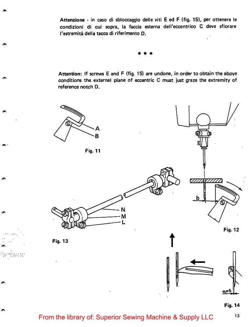
Inserire fino a battuta il crochet A nelTapposita sede del porta crochet e bloccarlosul piano di riferimento del gambo con la vite B (fig. 11).Controllare con il foglio di fase (allegato alia macchina) che le misure riportate su diesso corrispondano. Nel caso si dovessero effettuare alcune registrazioni operatecome segue:
1. Per ottenere la quota 'b' fig. 12 portare il crochet tutto a destra, allentare la viteL della fascetta M e agire sul tirante N della biella (fig. 13) sino ad ottenere laquota prescritta dalla tabella di fase.
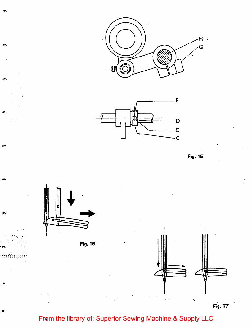
2. Per ottenere la quota 0,05 (fig. 14) che rappresenta la distanza fra la punta delcrochet e I'incavo dell'ago durante la sua corsa da destra a sinistra allentare lavite G (fig. 15) e registrare facendo ruotare I'albero H.
3. Sulle teste a punto ornamento tipo 171 e 173, la punta dell'ago interne,durante la sua discesa, deve coincidere con il punto di convergenza delle duelinee che formano il profile inferiore della lama del crochet (fig. 16)Sulle teste 174 a 2 aghi, a punto catenella doppia, la cruna di ogni ago durantela discesa deve essere allineata con il fore del rispettivo crochet (fig. 17).
4. Gli aghi nella lore discesa devono entrare in contatto con il dorse della lama delcrochet flettendo. Per ottenere questa condizione e necessario che ilprolungamento ideale della tacca di riferimento D (fig. 15), incisa sull'alberoprincipale, risuiti tangente al diametro esterno della vite E.
* * *
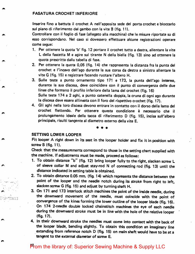
SETTING LOWER LOOPER
Fit looper A right down in its seat in the looper holder and fix it in position withscrew B (fig. 11).Check that the measurements correspond to those inthe setting chart supplied withthe machine. If adjustments must be made, proceed as follows:1. To obtain distance "b" (fig. 12) bring looper fully to the right, slacken screw L
of sleeve collar M and adjust stay-rod N of connecting rod (fig. 13) until thedistance indicated in setting table is obtained.
2. To obtain distance0.05 mm. (fig. 14) which represents the distance between thepoint of the looper and the needle notch during its stroke from right to left,slacken screw G (fig. 15) and adjust by turning shaft H.
3. On 171 and 173 interlock stitch machines the point of the inside needle, duringthe downward movement of the needle, must coincide with the point ofconvergence of the kines forming the lower outlineof the looper blade (fig. 16).On 174 2-needle double locked chainstitch machines the eye of each needleduring the downward stroke must be in line with the hole of the relative looper(fig. 17).
4. In their downward stroke the needles must come into contact with the back ofthe looper blade, bending slightly. To obtain this condition an imaginary lineextending from reference notch D (fig. 15) on main shaft would have to be at atangent to the external diameter of screw E.
12From the library of: Superior Sewing Machine & Supply LLC
(1^
(1^
Attenzione - in caso di sbioccaggio delle viti E ed F (fig. 15), per ottenere lecondizioni di cui sopra, la faccia esterna deii'eccentrico C deve sfiorare{'estremita della tacca di riferimento D.
* * *
Attention: If screws E and F (fig. 15) are undone, in order to obtain the aboveconditions the external plane of eccentric C must just graze the extremity ofreference notch D.
Fig. 11
Fig. 13 tFig. 12
Fig. 14
13From the library of: Superior Sewing Machine & Supply LLC
I
Fig. 15
Fig. 16
i *5 §
Fig. 17
14From the library of: Superior Sewing Machine & Supply LLC
TESTE CON CROCHET IN TANDEM
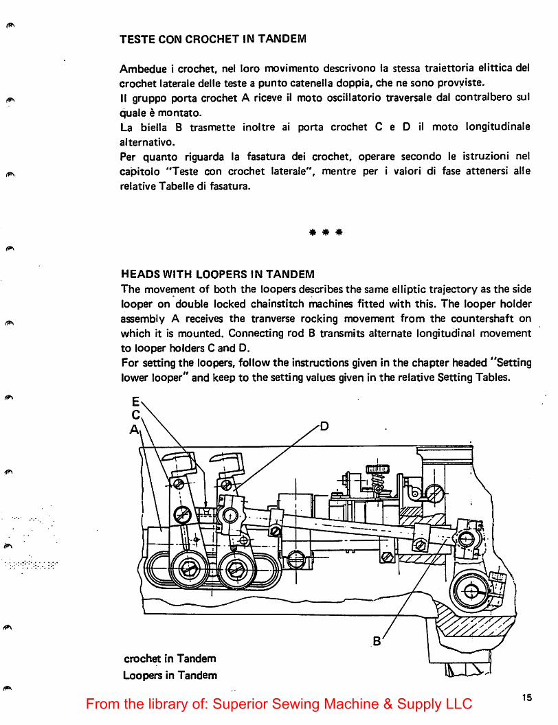
Ambedue i crochet, nel lore movimento descrivono la stessa traiettoria elittica delcrochet laterale delle teste a punto catenella doppia, che ne sono provyiste.II gruppo porta crochet A riceve il moto oscillatorio traversaie dal contralbero sulquale e montato.
La biella B trasmette inoltre ai porta crochet C e D il moto longitudinalealternativo.
Per quanto riguarda la fasatura del crochet, operate secondo le istruzioni nelcapitolo "Teste con crochet laterale", mentre per i valori di fase attenersi alle
relative Tabelle di fasatura.
* * ^
HEADS WITH LOOPERS IN TANDEM
The movement of both the loopers describes the same elliptic trajectory as the sidelooper on double locked chainstitch machines fitted with this. The looper holderassembly A receives the tranverse rocking movement from the countershaft onwhich it is mounted. Connecting rod B transmits alternate longitudinal movementto looper holders C and D.
For setting the loopers, follow the instructions given In the chapter headed "Settinglower looper" and keep to the setting values given in the relative Setting Tables.
crochet in Tandem
Loopers in Tandem cxs:
15From the library of: Superior Sewing Machine & Supply LLC
FASATURE CROCHET SUPERIORE
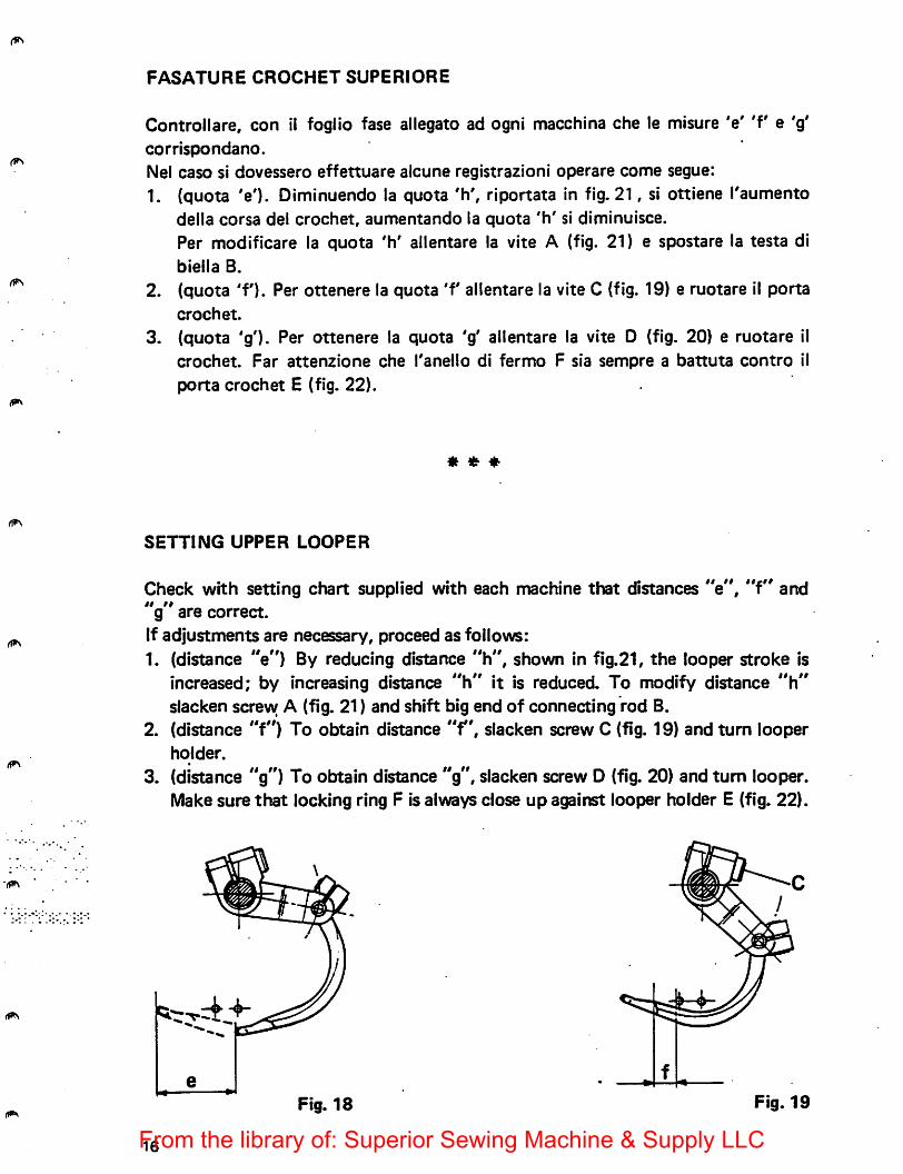
Controllare, con il foglio fase allegato ad ogni macchina che le misure 'e' 'f e 'g'corrlspondano.
Nel case si dovessero effettuare alcune registrazioni operare come segue:
1. (quota 'e'). Diminuendo la quota 'h', riportata in fig. 21, si ottiene I'aumentodella corsa del crochet, aumentando la quota 'h' si diminuisce.Per modificare la quota 'h' allentare la vite A (fig. 21) e spostare la testa dibiella B.
2. (quota 'f'). Per ottenere la quota 'f allentare la vite C (fig. 19) e ruotare il portacrochet.
3. (quota 'g'). Per ottenere la quota 'g' allentare la vite D (fig. 20) e ruotare ilcrochet. Far attenzione che I'anello di fermo F sia sempre a battuta contro il
porta crochet E (fig. 22).
« ♦
SETTING UPPER LOOPER
Check with setting chart supplied with each machine that distances "e", "f" and"g" are correct.If adjustments are necessary, proceed as follows:1. (distance "e") By reducing distance "h", shown in fig.21, the looper stroke is
increased; by increasing distance "h" it is reduced. To modify distance "h"slacken screvy A (fig. 21) and shift big end of connecting rod B.
2. (distance "f") To obtain distance "fslacken screw C (fig. 19) and turn looperholder.
3. (distance "g") To obtain distance "g", slacken screw D (fig. 20) and turn looper.Make sure that locking ring F is always close up against looper holder E (fig. 22).
Fig. 18 Fig. 19
16From the library of: Superior Sewing Machine & Supply LLC
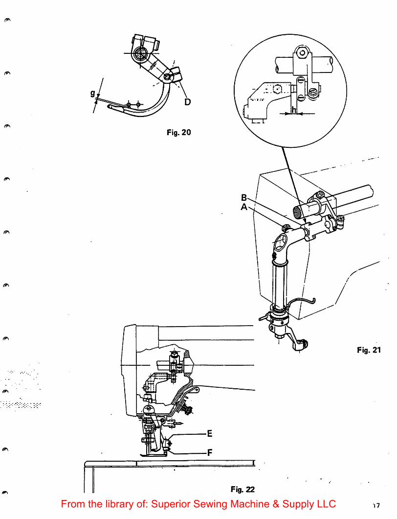
Fig. 20
Fig. 21
Fig. 22
•|7From the library of: Superior Sewing Machine & Supply LLC
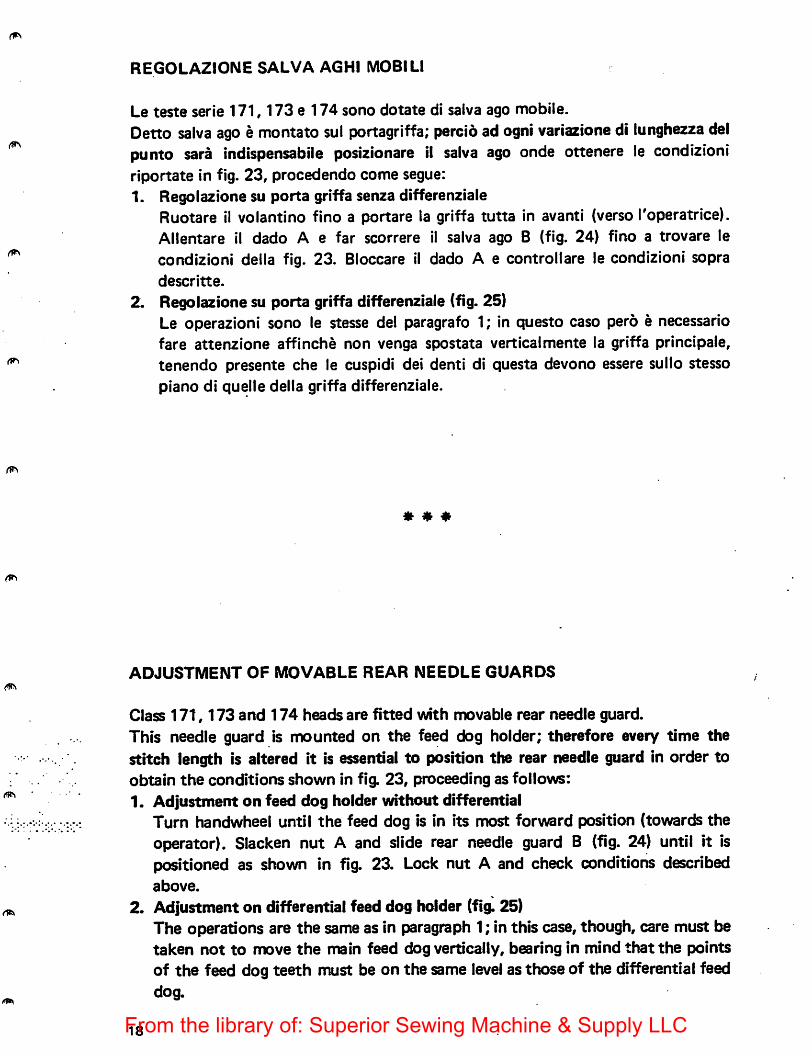
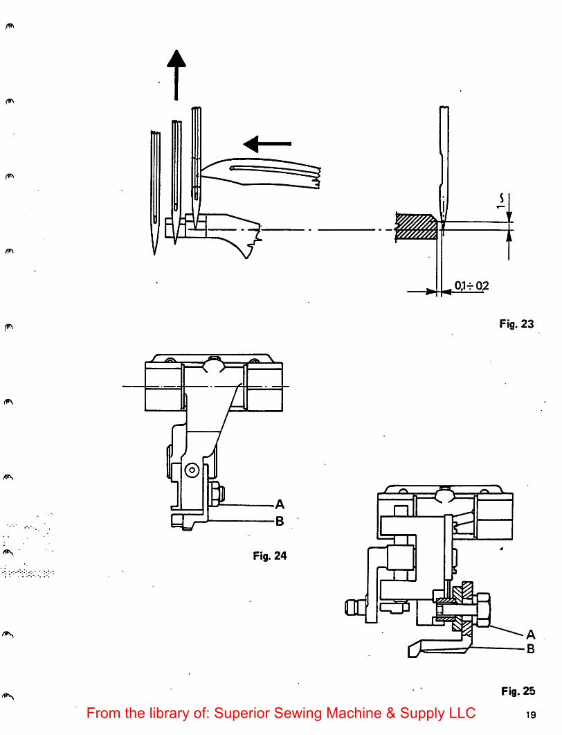
REGOLAZIONE SALVA AGHI MOBILl
Le teste serie 171,173 e 174 sono dotate di salva ago mobile.Detto salva ago e montato sul portagriffa; percid ad ogni variazione di lunghezza delpunto sara indispensabile posizionare il salva ago onde ottenere le condizioniriportate in fig. 23, procedendo come segue:1. Regolazione su porta griffa senza differenziale
Ruotare il volantino fino a portare la griffa tutta in avanti (verso Toperatrice).Allentare il dado A e far scorrere il salva ago B (fig. 24) fino a trovare lecondizioni della fig. 23. Bloccare il dado A e controllare le condizioni sopradescritte.
2. Regolazione su porta griffa differenziale (fig. 25)Le operazioni sono le stesse del paragrafo 1; in questo caso pero e necessariofare attenzione affinche non venga spostata verticalmente la griffa principale,tenendo presente che le cuspidi del denti di questa devono essere sullo stessopiano di quelle della griffa differenziale.
« ♦ ♦
ADJUSTMENT OF MOVABLE REAR NEEDLE GUARDS
Class 171,173 and 174 heads are fitted with movable rear needle guard.This needle guard is mounted on the feed dog holder; therefore every time thestitch length is altered it is essential to position the rear needle guard in order toobtain the conditions shown in fig. 23, proceeding as follows:1. Adjustment on feed dog holder without differential
Turn handwheel until the feed dog is in its most forward position (towards theoperator). Slacken nut A and slide rear needle guard B (fig. 24) until it ispositioned as shown in fig. 23. Lock nut A and check conditions describedabove.
2. Adjustment on differential feed dog holder (fig. 25)The operations are the same as in paragraph 1; in this case, though, care must betaken not to move the main feed dog vertically, bearing in mind that the pointsof the feed dog teeth must be on the same level as those of the differential feeddog.
18From the library of: Superior Sewing Machine & Supply LLC
©
a -A
-B
Fig. 24
Fig. 23
Fig. 25
19From the library of: Superior Sewing Machine & Supply LLC
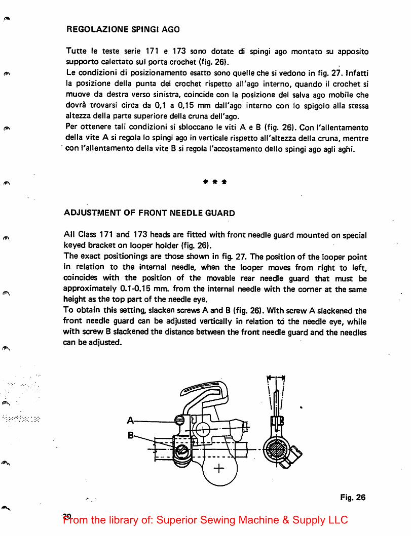
REGOLAZIONE SPIiMGl AGO
Tutte le teste serie 171 e 173 sono dotate di spingi ago montato su appositesupporto calettato sul porta crochet (fig. 26).Le condizioni di posizionamento esatto sono quelleche si vedono in fig. 27. Infattila posizione deila punta del crochet rispetto alTago interne, quando 11 crochet simuove da destra verso sinistra, coincide con la posizione del salva ago mobile chedovra trovarsi circa da 0,1 a 0,15 mm dall'ago interne con lo spigolo alia stessaaltezza della parte superiore della cruna delKago.Per ottenere tali condizioni si sbloccano le viti A e B (fig. 26). Con I'allentamentodella vite A si regola lo spingi ago in verticale rispetto all'altezza della cruna, mentrecon I'allentamento della vite B si regola I'accostamento dello spingi ago agli aghi.
* * *
ADJUSTMENT OF FRONT NEEDLE GUARD
All Class 171 and 173 heads are fitted with front needle guard mounted on specialkeyed bracket on looper holder (fig. 26).The exact positionings are those shown in fig. 27. The position of the looper pointin relation to the internal needle, when the looper moves from right to left,coincides with the position of the movable rear needle guard that must beapproximately 0.1-0.15 mm. from the internal needle with the corner at the same
height as the top part of the needle eye.To obtain this setting, slacken screws A and B (fig. 26). With screw A slackened thefront needle guard can be adjusted vertically in relation to the needle eye, whilewith screw B slackened the distance between the front needle guard and the needlescan be adjusted.
@
Fig. 26
20From the library of: Superior Sewing Machine & Supply LLC
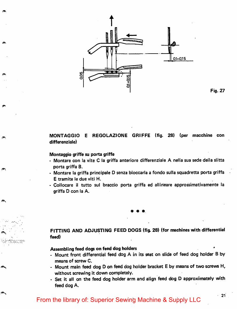
0,1+0.15
Fig. 27
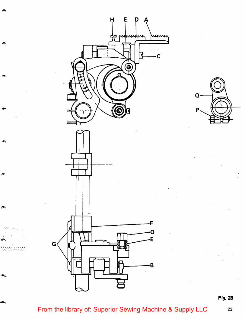
MONTAGGIO E REGOLAZIONE GRIFFE (fig. 28) (per macchine condifferenziaie)
Montaggio griffe su porta griffe• Montare con la vita C la griffa anteriore differenziaie A neila sua sede deila siitta
porta griffa B.• Montare la griffa principale D senza bloccaria a fondo sulla squadretta porta griffa
E tramite le due viti H.
- Collocare it tutto sul braccio porta griffa ed allineare approssimativamente lagriffa D con la A.
* * *.
FITTING AND ADJUSTING FEED DOGS (fig. 28) (for machines with differentialfeed)
Assembling feed dogs on feed dog holders- Mount front differential feed dog A in its seat on slide of feed dog holder B by
means of screw C.
- Mount main feed dog D on feed dog holder bracket E by means of two screws H,without screwing it down completely.
• Set it all on the feed dog holder arm and align feed dog D approximately withfeed dog A.
21
From the library of: Superior Sewing Machine & Supply LLC
Centratura griffe- Allentare le due viti G.
• Montare la placca d'ago e centrare in senso laterale la griffa A nelle feritoie dellaplacca d'ago spostando rintero gruppo differenziaie F.
• Bloccare le viti G.
- Allineare perfettamente la griffa principale D.
- Togliere la placca d'ago. Smontare la squadretta porta griffa E ed eseguire ilbloccaggio a fondo della griffa D sulla squadretta E tramite le viti H.
• Rimontare di nuovo la squadretta E e bloccare leggermente con la vite 0.- Rimontare la placca d'ago e, facendo ruotare ii voiantino nel senso di marcia, far
scorrere le griffe neila placca d'ago.- Se le griffe toccassero la placca d'ago sul fondo delle feritoie, allentare la vite P
della forcella Q.
• Ruotare il gruppo F ed eseguire la centratura delle griffe rispetto alle feritoie dellaplacca d'ago
• Bloccare leggermente la vite P.
« ♦ ♦
Centering the feed dogs• Slacken the two screws G.
• Mount needle plate and center feed dog A laterally in the needle plate slot,moving the whole differential assembly F.
- Tighten screws G- Align main feed dog D accurately• Remove the needle plate. Disassemble feed dog holder bracket E and fix feed dog
D firmly on bracket E by means of screws H.• Re-mount bracket E and fasten tightly with screw 0.
- Re-mount needle plate and, turning handwheel in the normal direction, makefeed dog run in needle plate.
- If the feed dog touches the bottom of the needle plate slot, slacken screw P offork Q. . •
• Turn assembly F and center feed dog in relation to needle plate slot.- Lightly fasten screw P.
22From the library of: Superior Sewing Machine & Supply LLC
H E D A
3—c
Fig. 28
23From the library of: Superior Sewing Machine & Supply LLC
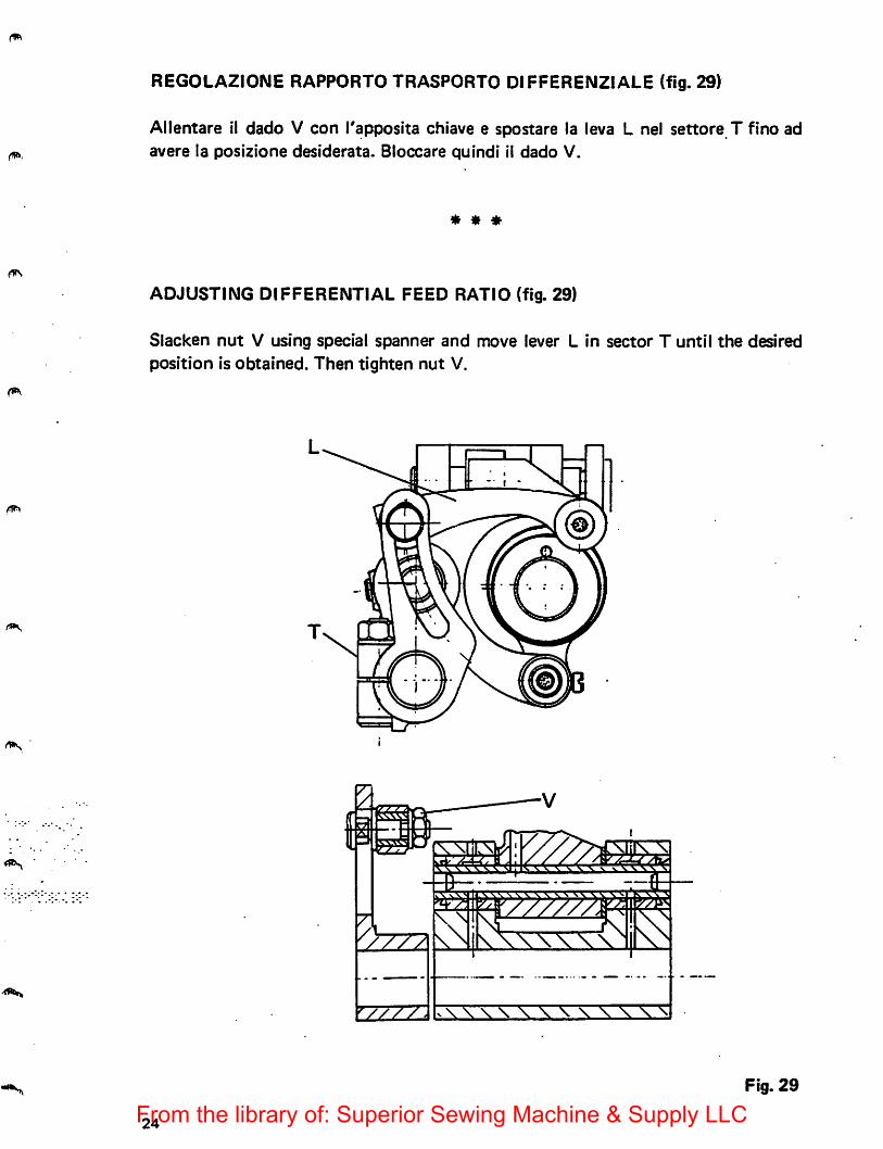
REGOLAZIONE RAPPORTO TRASPORTO DIFFERENZIALE (fig. 29)
Allentare il dado V con I'apposita chiave e spostare la leva L nel settore T fino adavere la posizione desiderata. Bloccare quindi il dado V.
* * *
ADJUSTING DIFFERENTIAL FEED RATIO (fig. 29)
Slacken nut V using special spanner and move lever L in sector T until the desiredposition is obtained. Then tighten nut V.
Fig. 29
24From the library of: Superior Sewing Machine & Supply LLC
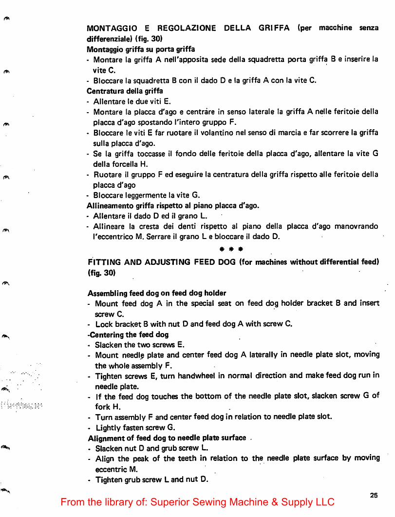
MONTAGGtO E REGOLAZIONE DELLA GRIFFA (per macchine senzadifferenziale) (fig. 30)Montaggio griffa su porta griffa• Montare la griffa A neii'apposita sede della squadretta porta griffa B e inserire la
vite C.
• Bloccare la squadretta B con il dado D e la griffa A con la vite C.Centratura della griffa
- Allentare le due viti E.
• Montare la placca d'ago e centrare in senso laterale la griffa A nelle feritoie dellaplacca d'ago spostando I'intero gruppo F.
• Bloccare le viti E far ruotare il volantino nel senso di marcia e far scorrere la griffa
sulla placca d'ago.
- Se la griffa toccasse il fondo delle feritoie della placca d'ago, allentare la vite Gdella forcella H.
- Ruotare il gruppo F ed eseguire la centratura della griffa rispetto alle feritoie dellaplacca d'ago
- Bloccare leggermente la vite G.Allineamento griffa rispetto al piano placca d'ago.- Allentare il dado D ed il grano L.
• Allineare la cresta dei denti rispetto al piano della placca d'ago manovrandoI'eccentrico M. Serrare il grano L e bloccare il dado D.
* * *
FITTING AND ADJUSTING FEED DOG (for machines without differential feed)
(fig. 30)
Assembling feed dog on feed dog holder• Mount feed dog A in the special seat on feed dog holder bracket B and insert
screw C.
- Lock bracket B with nut D and feed dog A with screw C.-Centering the feed dog• Slacken the two screws E.
• Mount needle plate and center feed dog A laterally in needle plate slot, movingthe whole assembly F.
- Tighten screws E, turn handwheel in normal direction and make feed dog run inneedle plate.
- If the feed dog touches the bottom of the needle plate slot, slacken screw G offork H.
- Turn assembly F and center feed dog in relation to needle plate slot.• Lightly fasten screw G.Alignment of feed dog to needle plate surface• Slacken nut D and grub screw L.- Align the peak of the teeth in relation to the needle plate surface by moving
eccentric M.
- Tighten grub screw L and nut D.
25
From the library of: Superior Sewing Machine & Supply LLC
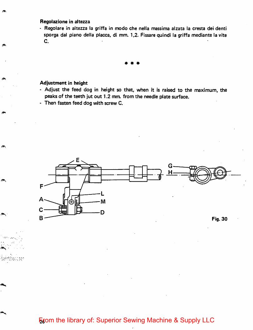
Regolaztone in altezza• Regoiare in aitezza la griffa in modo che nella massima alzata la cresta dei denti
sporga dal piano della placca, di mm. 1,2. Fissare quindi la griffa mediante la viteC.
* * *
Adjustment in height- Adjust the feed dog in height so that, when it is raised to the maximum, the
peaks of the teeth jut out 1.2 mra from the needle plate surface.• Then fasten feed dog with screw C.
Fig. 30
26From the library of: Superior Sewing Machine & Supply LLC
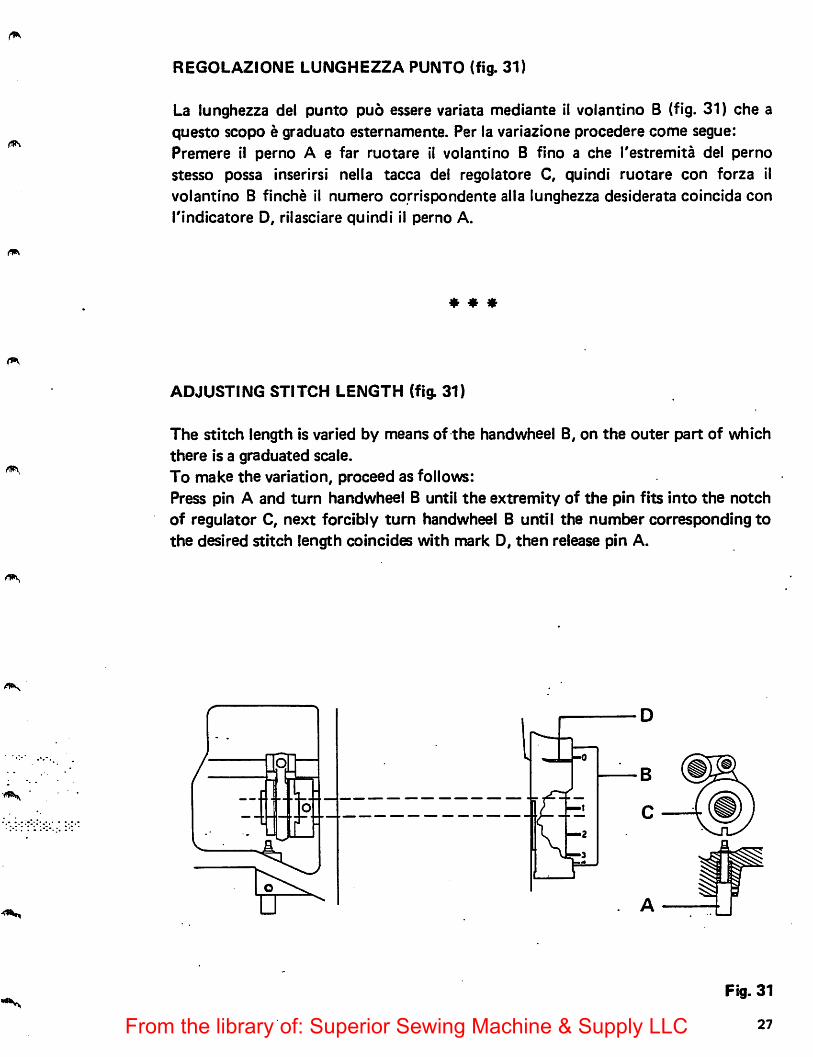
REGOLAZIONE LUNGHEZZA PUNTO (fig. 31)
La lunghezza del punto pud essere variata mediante il volantino B (fig. 31) che aquesto scopo e graduate esternamente. Per la variazione procedere come segue:Premere ii perno A e far ruotare 11 volantino B fino a che I'estremita del pernostesso possa inserirsi nella tacca del regolatore C, quindi ruotare con forza ilvolantino B finche il numero corrispondente alia lunghezza desiderata coincida con
rindicatore D, rilasciare quindi il perno A.
* * *
ADJUSTING STITCH LENGTH (fig. 31)
The stitch length is varied by means of the handwheel B, on the outer part of whichthere is a graduated scale.To make the variation, proceed as follows:Press pin A and turn handwheel B until the extremity of the pin fits into the notchof regulator C, next forcibly turn handwheel B until the number corresponding tothe desired stitch length coincides with mark D, then release pin A.
Fig. 31
27From the library of: Superior Sewing Machine & Supply LLC
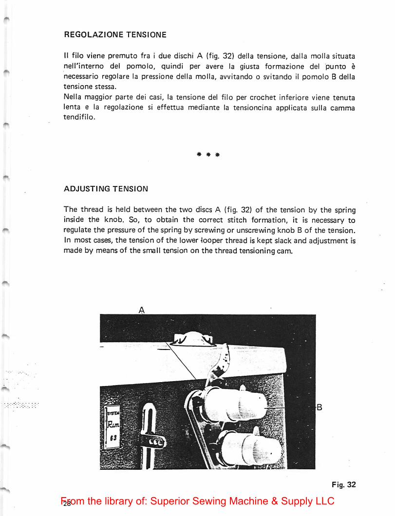
REGOLAZIONE TENSIONE
It filo viene premuto fra i due dischi A (fig. 32) delta tensione, dalla molla situatanell'interno del pomolo, quindl per avere la giusta formazione del punto enecessario regolare la pressione delta molla, avvitando o svitando il pomolo B deltatensione stessa.
Nella maggior parte dei casi, la tensione del filo per crochet inferiore viene tenutalenta e la regolazione si effettua mediante la tensioncina applicata sulla cammatendifilo.
* * m
ADJUSTING TENSION
The thread is held between the two discs A (fig. 32) of the tension by the springinside the knob. So, to obtain the correct stitch formation, it is necessary toregulate the pressure of the spring by screwing or unscrewing knob B of the tension.In most cases, the tension of the lower -looper thread is kept slack and adjustment ismade by means of the small tension on the thread tensioning cam.
mm
^rMMniirnr^
Fig. 32
From the library of: Superior Sewing Machine & Supply LLC
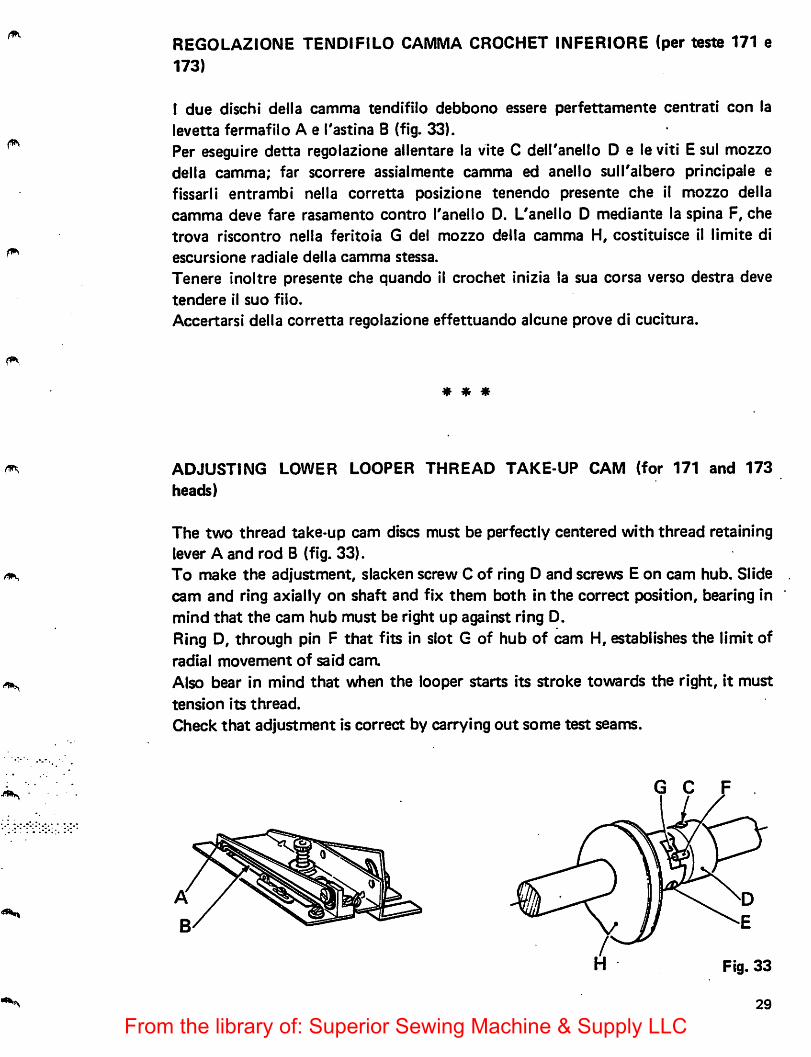
REGOLAZIONE TENDIFILO GAMMA CROCHET INFERIORE (per testa 171 e173)
I due dischi della camma tendifilo debbono essere perfettamente centrati con lalevetta fermafilo A e I'astina B (fig. 33).Per eseguire detta regoiazione ailentare la vite C deiranello D e le viti E sul mezzodella camma; far scorrere assialmente camma ed anello sull'albero principale efissarii entrambi nella corretta posizione tenendo presents che 11 mezzo dellacamma deve fare rasamento centre Tanelle D. L'anelle D mediants la spina F, chetreva riscentre nella feriteia G del mezzo della camma H, cestituisce il limits di
escursiene radiale della camma stessa.
Tenere ineltre presents che quande il crochet inizia la sua cersa verse destra devetenders il sue file.
Accertarsi della corretta regoiazione effettuande alcune prove di cucitura.
* * *
ADJUSTING LOWER LOOPER THREAD TAKE-UP CAM (for 171 and 173
heads)
The two thread take-up cam discs must be perfectly centered with thread retaininglever A and rod B (fig. 33).To make the adjustment, slacken screw C of ring D and screws E on cam hub. Slidecam and ring axially on shaft and fix them both in the correct position, bearing inmind that the cam hub must be right up against ring D.Ring D, through pin F that fits in slot G of hub of cam H, establishes the limit ofradial movement of said cara
Also bear in mind that when the looper starts its stroke towards the right, it musttension its thread.
Check that adjustment is correct by carrying out some test seams.
G C
Fig. 33
From the library of: Superior Sewing Machine & Supply LLC
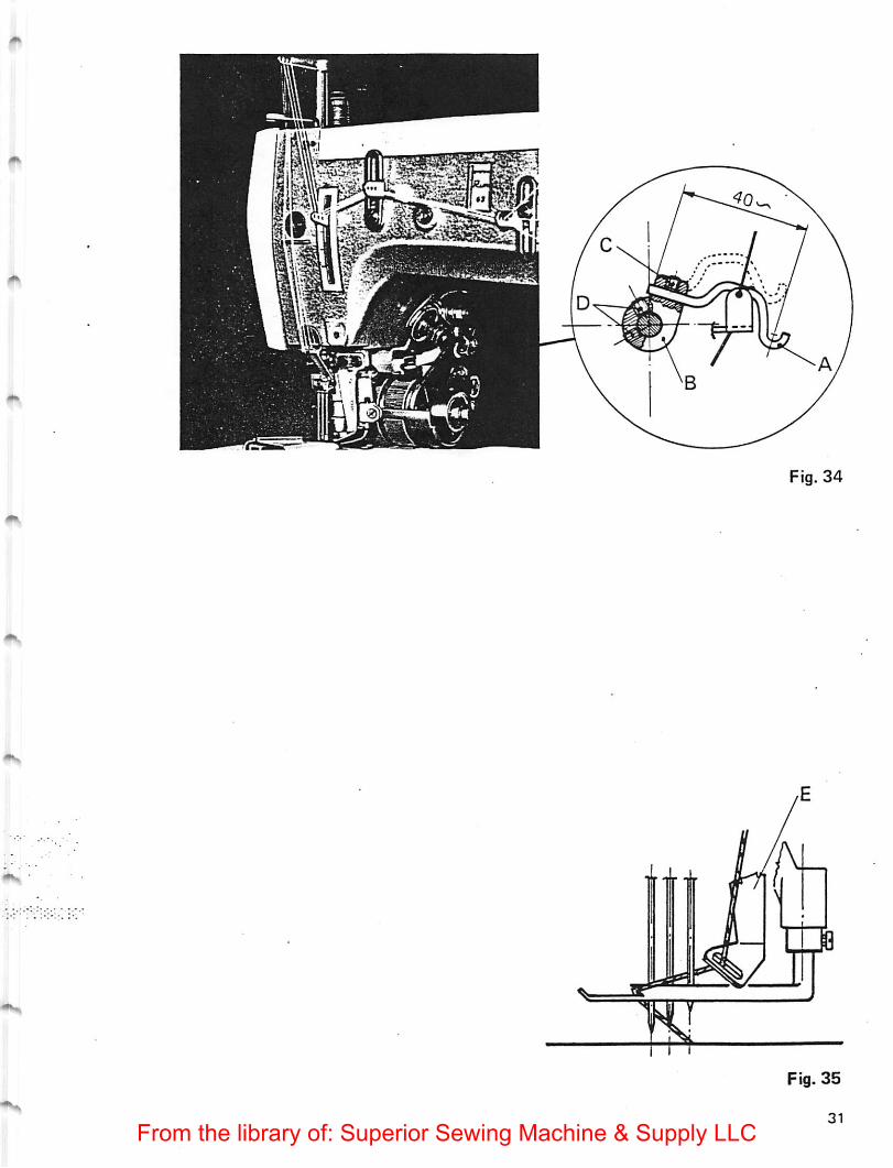
REGOLAZIONE TENDIFILO CROCHET SUPERIORE
Al governo del filo del crochet di copertura (fig. 34) sulle teste 173 e predispostaun'asttna tirafilo A montata suiranello B.
Le condizioni ottime di fase si hanno quando con crochet superiore spostato tutto
verso sinistra, I'astina A tiene il filo in tensione. L'azione dell'astina A deve cessarequando la punta delTago sinistro e ben penetrato nel triangolo di filo formato dalfilo di copertura come rappresentato in fig. 35.L'astina A si puo regolare assialmente allentando la vite C ed angolarmente
allentando le viti D (fig. 34).La camma E (fig. 35) concorre alia formazione del triangolo del filo. Puo essereregolata verticalmente ed orientate secondo la necessita.
* * *
ADJUSTING UPPER LOOPER THREAD TAKE-UP
To control the thread of cover looper (fig. 34) on Class 173 machines there is athread tensioner rod A mounted on ring B.Optimum setting conditions are obtained when rod A holds the thread tensionedwhen the top looper is fully to the left. The action of rod A must stop when the
point of the left hand needle has penetrated well into the thread triangle formed bythe cover thread, as shown in fig. 35.Rod A can be adjusted axially by slackening screw C and angularly by slackeningscrews D (fig. 34).Cam E (fig. 35) helps in forming the thread triangle. It can be adjusted verticallyand positioned directionally as required.
30From the library of: Superior Sewing Machine & Supply LLC
From the library of: Superior Sewing Machine & Supply LLC
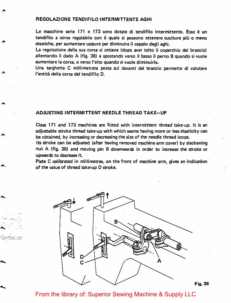
REGOLAZIONE TENDIFILO INTERMITTENTE AGHI
Le macchine serie 171 e 173 sono dotate di tendifilo intermittente. Esso e un
tendifiio a corsa regolabile con ii quaie si possono ottenere cuciture piu o menoelastiche, per aumentare oppure per diminuire 11 cappio degii aghi.La regolazione delta sua corsa si ottiene (dopo aver tolto it coperchio del braccio)allentando. il dado A (fig. 36) e spostando verso il basso il perno B quando si vuoleaumentare la corsa, o verso Talto quando si vuole diminuirla.Una targhetta C millimetrata posta sul davanti del braccio permette di valutareTentita delta corsa del tendifilo D.
ADJUSTING INTERMITTENT NEEDLE THREAD TAKE-UP
Class 171 and 173 machines are fitted with intermittent thread take-up. It is anadjustable stroke thread take-up with which seams having more or less elasticity canbe obtained, by increasing or decreasing the size of the needle thread loops.Its stroke can be adjusted (after having removed machine arm cover) by slackeningnut A (fig. 36) and moving pin B downwards in order to increase the stroke orupwards to decrease it.
Plate C calibrated in millimetres, on the front of machine arm, gives an indicationof the value of thread take-up D stroke.
Fig. 36
From the library of: Superior Sewing Machine & Supply LLC
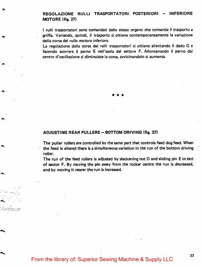
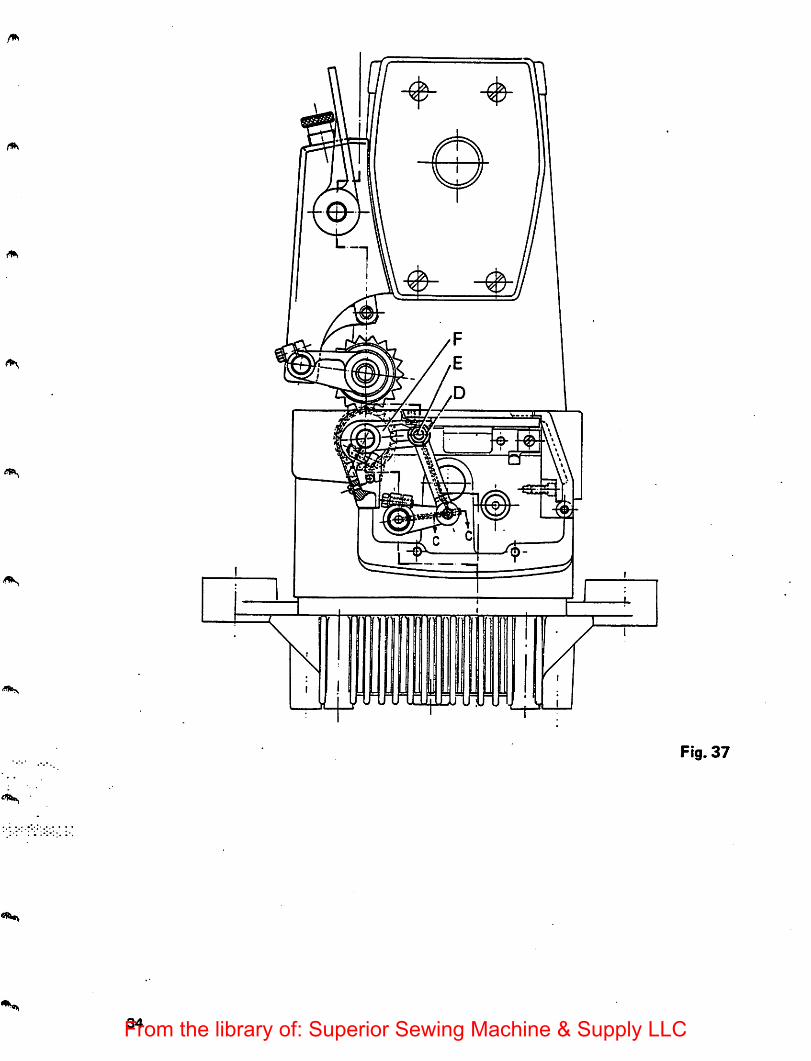
REGOLAZIONE RULLI TRASPORTATORI POSTERIORI - INFERIORE
MOTORE (fig. 37)
I ruili trasportatori sono comandati dalto stesso organo che comanda il trasporto agriffa. Variando, quiadi, il trasporto si ottiene contemporaneamente la variazionedella corsa del rullo motore inferiore.
La regolazione della corsa dei rulli trasportatori si ottiene ailentando il dado D efacendo scorrere il perno E nell'asola dei settore F. Allontanando il perno dalcentro d'oscillazione si diminuisce la corsa, avvicinandolo si aumenta.
* * *
ADJUSTING REAR PULLERS - BOTTOM DRIVING (fig. 37)
The puller rollers are controlled by the same part that controls feed dog feed. Whenthe feed is altered there is a simultaneous variation in the run of the bottom drivingroller.
The run of the feed rollers is adjusted by slackening nut D and sliding pin E in slotof sector F. By moving the pin away from the rocker centre the run is decreased,and by moving it nearer the run is increased.
33
From the library of: Superior Sewing Machine & Supply LLC
0
0
pFig. 37
34From the library of: Superior Sewing Machine & Supply LLC
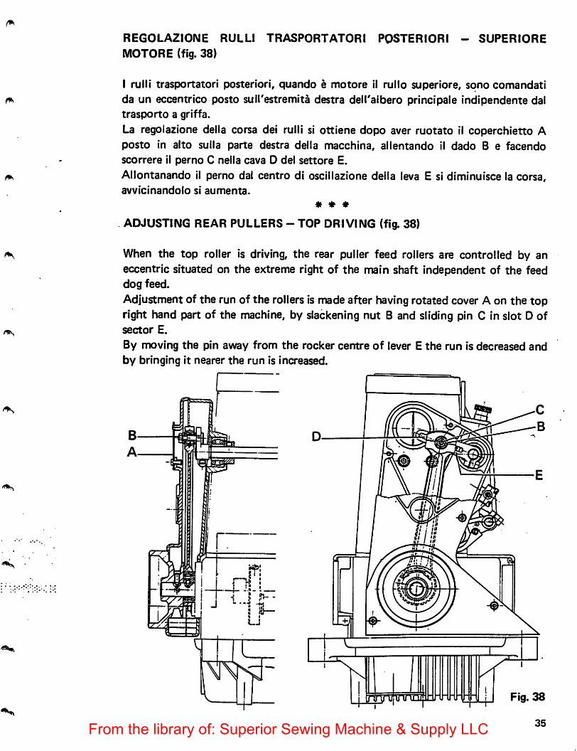
REGOLAZIONE RULLl
MOTORE (fig. 38)TRASPORTATORI POSTERIORI - SUPERIORE
I rulli trasportatori posteriori, quando e motore il rullo superiore, sono comandatida un eccentrico posto sull'estremita destra dell'albero principale indipendente daltrasporto a griffa.La regolazione della corsa dei rulli si ottiene dopo aver ruotato il coperchietto Aposto in alto sulla parte destra della macchina, allentando il dado B e facendoscorrere il perno C nella cava D del settore E.
Allontanando il perno dal centro di oscillazione della leva E si diminuisce la corsa,avvicinandolo si aumenta.
« ♦ ♦
ADJUSTING REAR PULLERS - TOP DRIVING (fig. 38)
When the top roller is driving, the rear puller feed rollers are controlled by aneccentric situated on the extreme right of the main shaft Independent of the feeddog feed.Adjustment of the run of the rollers is made after having rotated cover A on the topright hand part of the machine, by slackening nut B and sliding pin C in slot D ofsector E.
By moving the pin away from the rocker centre of lever E the run is decreased andby bringing it nearer the run is increased.
mnnn/iij Fig. 38
From the library of: Superior Sewing Machine & Supply LLC
MANUTENZIONE
Sono qui di seguito elencate le operazioni periodiche di manutenzione necessarieper mantenere la macchina sempre in perfetta efficienza.
Ogni giorno
Pulire tutti gli organi della macchina relativi a! trasporto e alia formazione delpunto. •
Controllare il livello olio.
Ogni settimanaSmontare la placca ago e pulire griffe, crochet e trasporto.
Ogni 3 mesiSostituire I'olio e pulire il filtro principale.Per scaricare I'olio dalla bacinella svitare il tappo di scarico B (fig. 39).Per accedere al filtro svitare le due viti D che fissano il tappo E alia bacinella.Aiutandosi eventualmente con una chiave del tipo illustrato in figure, avvitata nelforo centrale del tappo, sfilare lo stesso - completo di filtro - dalla bacinella.Togliere il filtro del tappo, pulirlo con benzine e soffiarlo con aria a bassa pressione.
* * *
MAINTENANCE
Listed below are the periodic maintenance operations which should be carried outto keep the machine in perfect condition.
Everyday
Clean all the parts of the machine involved in the feed and in the stitch formation.
Every week
Remove needle plate and clean feed dogs, looper and feed.
Every 3 months
Replace the oil and clean the main filterTo empty the oil out of the sump, unscrew drain plug B (fig. 39).To reach filter, undo the two screvys D that fix plug E to sump.Using a spanner of the type shown in the sketch, if necessary, screwed to the centrehole of plug, remove plug, complete with filter, from sump.Take filter out of plug, clean it with petrol and blow it with low pressurecompressed air.
36From the library of: Superior Sewing Machine & Supply LLC
Riavvolgere ii filtro sul tappo, imbevendolo con olio pulito. RImontare ii tappo discarico ed il tappo con filtro, assicurandosi dell'efficienza dell'anello di tenuta edella sua corretta posizione nella gola del tappo.Effettuare quindi il rifornimento, introducendo circa 750 grammi di olio VR 604
im, (Esso Standard Teresso 43) osservando le indicazioni riportate al capitolo"RIFORNIMENTO OLIO".
* * *
Replace filter, soaked with clean oil, in plug. Replace drain plug and plug withfilter, ensuringthat sealing ring is efficient and positioned correctly in the mouth ofthe plug.
Then refill sump, using approximately 750 grams of VR 604 oil (Esso StandardTeresso 43), following instructions given in paragraph headed "LUBRICATION
37From the library of: Superior Sewing Machine & Supply LLC
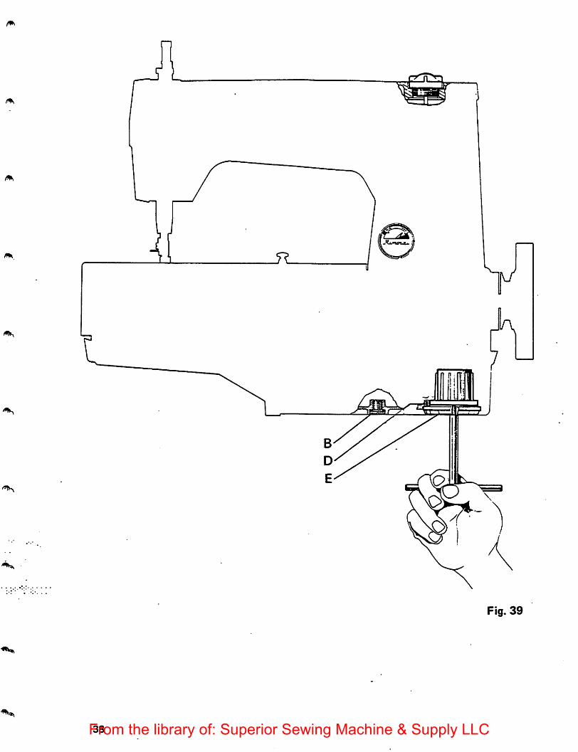
Fig. 39
38From the library of: Superior Sewing Machine & Supply LLC
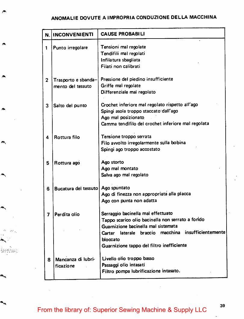
ANOMALIE OOVUTE A IMPROPRIA CONOUZIONE DELLA MACCHINA
N. NCONVENIENTl CAUSE PROBABILI
1 'unto irregolare Tension! mal regolate
Tendifili mal regolatiinfilatura sbagliata
Filati non calibrati
2 Trasporto e sbanda-
mento del tessuto
Pressione del piedino insufficiente
Griffe mal regolate
Differenziale mal regolato
3 Salto del punto Crochet infer!ore mal regolato rispetto all'agoSpingi asola troppo staccato dall'agoAgo mal posizionatoGamma tendifilo del crochet inferiore mal regolata
4 Rottura file Tensione troppo serrata
Filo awolto irregolarmente sulta bobinaSpingi ago troppo accostato
5 Rottura ago Ago storto
Ago mal montatoSalva ago mal regolato
6 Bucatura del tessuto Ago spuntato
Ago di finezza non appropriata alia placcaAgo con punta non adatta
7 Perdita olio Serraggio bacinella mal effettuatoTappo scarico olio bacinella non serrato a foridoGuamizione bacinella mal sistemata
Carter laterale braceio macchina insufficientemente
bloccato
Guamizione tappo del filtro inefficiente
8 Mancanza di iubri-
ficazione
Livello olio troppo basso
Passaggi olio intasatiFiltro pompa lubrificazione intasato.
39
From the library of: Superior Sewing Machine & Supply LLC
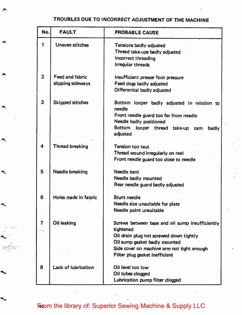
TROUBLES DUE TO INCORRECT ADJUSTMENT OF THE MACHINE
No. FAULT PROBABLE CAUSE
1 Uneven stitches Tensions badly adjustedThread take-ups badly adjustedIncorrect threadingIrregular threads
2 Feed and fabric
slipping sidewaysInsufficient presser foot pressureFeed dogs badly adjustedDifferential badly adjusted
3 Skipped stitches Bottom looper badly adjusted in relation toneedle
Front needle guard too far from needleNeedle badly positionedBottom looper thread take-up cam badlyadjusted
4 Thread breaking Tension too taut
Thread wound irregularly on reelFront needle guard too close to needle
5 Needle breaking Needle bent
Needle badly mountedRear needle guard badly adjusted
6 Holes made in fabric Blunt needle
Needle size unsuitable for plateNeedle point unsuitable
7 Oil leaking Screws between base and oil sump insufficientlytightenedOil drain plug not screwed down tightlyOil sump gasket badly mountedSide cover on machine arm not tight enoughFilter plug gasket inefficient
8 Lack of lubrication Oil level too low
Oil tubes cloggedLubrication pump filter clogged
40From the library of: Superior Sewing Machine & Supply LLC
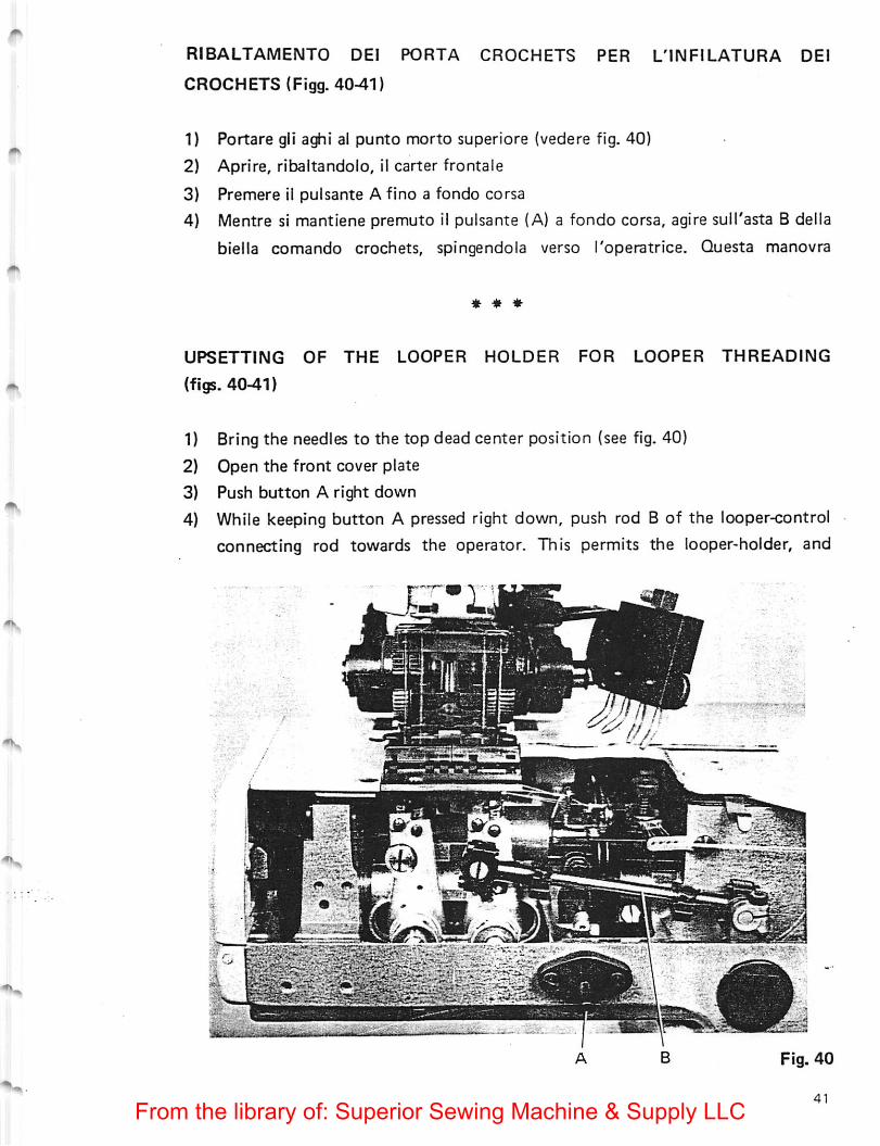
RIBALTAMENTO DEI PORTA CROCHETS PER L'llMFILATURA DEI
CROCHETS (Figg. 40-41)
1) Portare gli aghi al punto morto superiore (vedere fig. 40)
2) Aprire, ribaitandolo, il carter frontale
3) Premere 11 pulsante A fino a fondo corsa
4) Mentre si mantlene premuto il pulsante (A) a fondo corsa, agire sull'asta B della
biella comando crochets, spingendola verso Toperatrice. Questa manovra
* * *
UPSETTING OF THE LOOPER HOLDER FOR LOOPER THREADING
(figs. 40-41)
1) Bring the needles to the top dead center position (see fig. 40)
2) Open the front cover plate
3) Push button A right down
4) While keeping button A pressed right down, push rod B of the looper-control
connecting rod towards the operator. This permits the looper-holder, and
From the library of: Superior Sewing Machine & Supply LLC
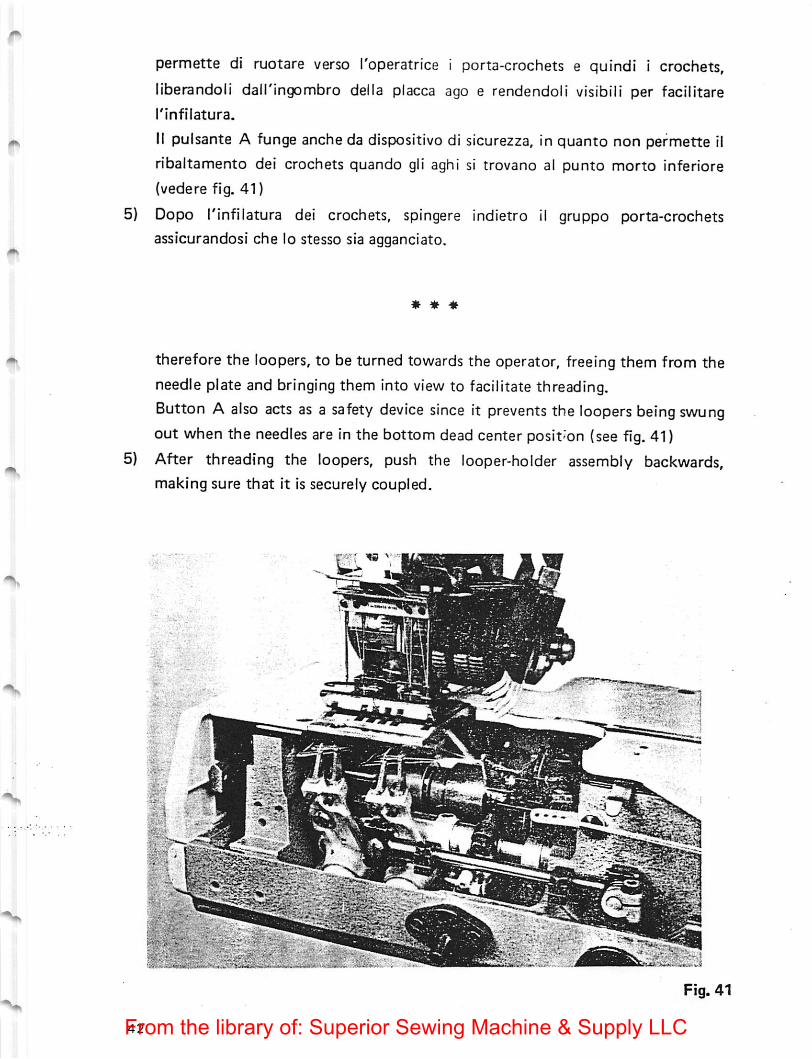
permette di ruotare verso I'operatrice i porta-crochets e quindi i crochets,
liberandoli dall'ingombro della placca ago e rendendoli visibili per facilitare
rinfilatura.
II pulsante A funge anche da dispositive di sicurezza, in quanto non permette tl
ribaltamento dei crochets quando gli aghi si trovano a! punto morto inferiore
(vedere fig. 41)
5) Dopo rinfilatura dei crochets, spingere indietro il gruppo porta-crochets
assicurandosi che lo stesso sia agganciato.
« * «
therefore the loopers, to be turned towards the operator, freeing them from the
needle plate and bringing them into view to facilitate threading.Button A also acts as a safety device since it prevents the loopers being swungout when the needles are in the bottom dead center position (see fig. 41)
5) After threading the loopers, push the looper-holder assembly backwards,making sure that it is securely coupled.
..".j .
Fig. 41
From the library of: Superior Sewing Machine & Supply LLC