SMARTPHONES ANALYSIS – ESTIMATING RNC UNIT … Doc... · iii Motivazione La popolarità crescente...
81
POLITECNICO DI MILANO Polo Territoriale di Como Scuola di Ingegneria dell'Informazione Corso di Laurea Magistrale in Ingegneria Informatica SMARTPHONES ANALYSIS – ESTIMATING RNC UNIT LOAD Relatore: Prof. Antonio Capone Tesi di Laurea di: Maja Lazarovska 764510 ANNO ACCADEMICO 2011-2012
-
Upload
nguyentruc -
Category
Documents
-
view
221 -
download
4
Transcript of SMARTPHONES ANALYSIS – ESTIMATING RNC UNIT … Doc... · iii Motivazione La popolarità crescente...

POLITECNICO DI MILANO Polo Territoriale di Como
Scuola di Ingegneria dell'Informazione
Corso di Laurea Magistrale in Ingegneria Informatica
SMARTPHONES ANALYSIS –
ESTIMATING RNC UNIT LOAD
Relatore: Prof. Antonio Capone
Tesi di Laurea di:
Maja Lazarovska 764510
ANNO ACCADEMICO 2011-2012

i
Contents Motivazione ...................................................................................................................... iii
Motivation ......................................................................................................................... iv
Acknowledgements ........................................................................................................... v
Abbreviations ................................................................................................................... vi
1 Introduction ............................................................................................................... 1
2 UMTS Architecture ................................................................................................... 3
2.1 UTRAN Architecture .......................................................................................... 5
2.2 UTRAN Interfaces and Signaling ....................................................................... 7
3 Transport Channels ................................................................................................. 10
3.1 Dedicated Transport Channel ........................................................................... 10
3.2 Common Transport Channels ........................................................................... 10
4 HSPA and HSPA+ ................................................................................................... 12
4.1 HSDPA ............................................................................................................. 12
4.2 HSUPA ............................................................................................................. 14
4.3 HSPA+ .............................................................................................................. 16
5 Radio Resource Management ................................................................................. 21
5.1 RRC Connection States..................................................................................... 24
6 Smartphones ............................................................................................................ 26
6.1 Understanding smartphones behavior ............................................................... 27
6.1.1 Always-On-Line Applications ...................................................................... 31
6.1.2 Always-On-Line PDP Context ..................................................................... 32
6.1.3 Fast Dormancy .............................................................................................. 35
7 Radio Network Controller ...................................................................................... 39
7.1 NSN RNC2600 ................................................................................................. 42
7.1.1 Hardware Characteristics .............................................................................. 42
7.1.2 Software Characteristics ............................................................................... 45
7.2 Huawei BSC6900.............................................................................................. 45
7.2.1 Hardware Characteristics .............................................................................. 46
7.2.2 Software Characteristics ............................................................................... 47
8 Estimation of the Unit Loads .................................................................................. 48
8.1 Key Performance Indicators ............................................................................. 48
8.2 NSN Units ......................................................................................................... 50
8.2.1 ICSU Model .................................................................................................. 50
8.2.2 DMPG Model................................................................................................ 57
8.3 Huawei Units .................................................................................................... 61

ii
8.3.1 SPU Model .................................................................................................... 61
8.3.2 DPU Model ................................................................................................... 64
8.4 Review .............................................................................................................. 67
9 Future Work ............................................................................................................ 68
10 Conclusion ................................................................................................................ 69
References ........................................................................................................................ 71

iii
Motivazione
La popolarità crescente delle tecnologie e delle applicazioni mobili sta attirando giorno
per giorno gli utenti che sfruttano sempre più i nuovi servizi a banda larga in mobilità che
nelle loro vite, il loro lavoro e il loro modo di comunicare e di interagire con i loro amici,
familiari e colleghi. La richiesta di un’alta qualità del servizio sta quindi aumentando, e
un miglioramento delle tecnologie mobili è necessario per ispirare e motivare nuove idee
che potrebbero migliorare il nostro modo di comunicare e il nostro modo di accedere alle
informazioni disponibili su Internet. Questo ha spinto i fornitori di apparati e gli operatori
ad accelerare alcune evoluzioni nella rete radiomobile per soddisfare le esigenze dei loro
clienti.
Il consumo dei dati mobili ha iniziato a crescere molto velocemente, spingendo gli
operatori ad gestire una notevole mole di dati, generata principalmente dagli utenti
connessi tramite laptop. Con l'arrivo degli smartphone, gli operatori in un primo tempo
hanno ritenuto sufficiente la prestazione in quanto questi nuovi utenti generavano dei
volumi decisamente più contenuti di traffico dati (circa un sesto di quella dei laptop).
Dopo poco è però emerso un nuovo collo di bottiglia, infatti il gran numero di
applicazioni always-on-line ha cambiato le condizioni la congestione della rete. Tutte le
connessioni generate da questi applicativi infatti, “instant messaging”, “modifica dello
stato di Facebook”, “ricevere una nuova email”, portano piccole quantità di dati, ma
molto traffico di segnalazione che apre e chiude la sessione di dati.
Con l’implementazione delle reti WCDMA, il traffico dati è stato attivato, ma anche la
qualità della voce è stata migliorata. Con la sola Release 99, è stata offerta dagli operatori
la velocità massima di 384 kbps. Implementando l’evoluzione di HSPA, le velocità hanno
raggiunto dei valori fino a 14,4 Mbps e 42 Mbps con HSPA +. Quindi, la velocità non è
un problema, ma cosa dire della segnalazione?

iv
Motivation
The growing popularity of mobile technologies and applications is attracting day by day
users that are looking for new mobile broadband services that interweave their lives, their
work, and the way they communicate and interact with their friends, family and
colleagues. Thus, the demand of a new quality of experiences is rising and an
improvement on the mobile technologies is needed inspiring and motivating new ideas
that might improve the way we communicate and the way we access the information
available on the Internet. This has put the vendors and the operators into an urgent
position to make some changes in the network in order to satisfy the need of their
customers.
Mobile data consumption started to grow really fast, leading the broadband operators to a
task to provide enough data capacity for the laptop users. After the arrival of the
smartphones, the operators were happy with their performance in terms of data traffic
generation (about one-sixth of the laptops). But, the great number of always-on-line
applications is what makes the congestion in the network. All this small connections to
the network for instant messaging, changing Facebook status, receiving a new email, are
carrying small amounts of data, but so much signaling traffic that opens and closes the
data session.
With the deployment of the WCDMA networks, data was enabled, but also the voice
quality was improved. A speed of maximum 384 kbps for laptop users was offered by the
operators. Deploying HSPA on the top of it, rates reached up to 14.4 Mbps and now
reaching amazing 42 Mbps with HSPA+. So, the speed is not an issue, but what about the
signaling?

v
Acknowledgements
I would like to express my deepest gratitude to my supervisor Luisa Venturini, from
whom I have learned a lot, for her patient guidance and enthusiastic encouragement
during my six months in Vodafone Italy. I am also particularly grateful to Lucia Levi,
who has always been glad to share her knowledge with me, and whose valuable
suggestions and advices, not only professional, have been a great help. Moreover, I
would like to thank the employees in Vodafone Italy for their willingness to give me a
part of their time so generously and for their assistance during my internship. My grateful
thanks are extended to prof. Antonio Capone as well, for accepting to be the academic
supervisor of this thesis and for giving useful critiques of my work.
Finally, I wish to thank my parents and my sister for their endless support and
encouragement throughout my studies without which these two years abroad would have
been really hard.

vi
Abbreviations ACK ACKnowledgement ALCAP Access Link Control Application Part AMC Adaptive Modulation and Coding AMR Adaptive Multi Rate ARQ Automatic Repeat-reQuest, BC BroadCast BCH Broadcast Channel BHCA Busy Hour Call Attempts BSC Base Station Controller CBC Cell Broadcast Center CN Core Network C-NBAP Common NBAP CPC Continuous Packet Connectivity CPCH Common Packet Channel CQI Channel Quality Indicator CRNC Controlling RNC CS Circuit Switch DCH Dedicated Channel DL DownLink DMCU Data and Macro Diversity Combining Unit DMPG Data and Macro Diversity Processor Group D-NBAP Dedicated NBAP DPCCH Dedicated Physical Control Channel DPCH Dedicated Physical Channel DPDCH Dedicated Physical Data Channel DRNC Drift RNC DRX Downlink Discontinuous Reception DSCH Downlink Shared Channel DTX Uplink Discontinuous Transmission E-AGCH E-DCH Absolute Grant Channel E-DCH Enhanced DCH E-DPCCH Enhanced DPCCH E-DPDCH Enhanced DPDCH E-HICH E-DCH HARQ Indication Channel EPR Extended Processing Rack EPS Extended Processing Subrack ERGCH E-DCH Relative Grant Channel FACH Forward Access Channel F-DPCH Fractional DPCH FP Frame Protocol GGSN Gateway GPRS Support Node GMSC Gateway MSC GPRS General Packet Radio Service

vii
GSM Global System for Mobile communications GTP GPRS Tunneling Protocol HARQ Hybrid ARQ HC High Capacity HLR Home Location Register HS-DSCH High Speed DSCH HSDPA High Speed Downlink Packet Access HS-DPCCH High Speed Dedicated Physical Control Channel HS-PDSCH High Speed Physical Downlink Shared Channel HS-SCCH High Speed Shared Control Channel HSPA High Speed Packet Access HSUPA High Speed Uplink Packet Access ICSU Interface Control and Signaling Unit IP Internet Protocol KPI Key Performance Indicator LMU Location Measurement Unit MAC Media Access Control ME Mobile Equipment MIMO Multiple Input Multiple Output MPR Main Processing Rack MPS Main Processing Subrack MSC Mobile Services Switching Center NACK Negative ACK NAS Non Access Stratum NAT Network Address Translator NBAP Node B Application Part NPGEP Network Processor Gigabit Ethernet Protected NRT Non-Real Time NSN Nokia Siemens Networks OM Operation and Maintenance OS Operating System OSS Operations Support System PCH Paging Channel PDCP Packet Data Convergence Protocol PDU Packet Data Unit PDP Packet Data Protocol PLMN Public Land Mobile Network PS Packet Switch QAM Quadrature Amplitude Modulation QoS Quality of Service RAB Radio Access Bearer RACH Random Access Channel RAN Radio Access Network RANAP RAN Application Part RAT Radio Access Technology RLC Radio Link Control

viii
RNC Radio Network Controller RNS Radio Network Subsystem RNSAP Radio Network Subsystem Application Part RRC Radio Resource Control RRM Radio Resource Management SF Spreading Factor SGSN Serving GPRS Support Node SHO Soft HandOver SMLC Serving Mobile Location Center SRNC Serving RNC SRNS Serving Radio Network Subsystem SRVCC Single Radio Voice Call Continuity SRVCC TCP Transmission Control Protocol TTI Transmission Time Interval UE User Equipment UMTS Universal Mobile Telecommunications System UL UpLink URA UTRAN Registration Area USIM UMTS Subscriber Identity Module UTRAN UMTS Terrestrial Radio Access Network VHC Very High Capacity VIK Vodafone Internet Key VLR Visitor Location Register VoIP Voice over IP WCDMA Wideband Code Division Multiple Access
1
1 Introduction
Led by the huge demand of the smartphones on the market and by the desire to offer a
better quality to the customers, the main idea of this thesis is to provide a model that will
estimate the behavior of the network that changes as the number of smartphones
constantly grows, and in this way to provide useful information for the network planning
in the future. The unexpected behavior in a 3G network is mostly due to the great amount
of signaling traffic generated by the large number of smartphones connected to the
network. This signaling is fully utilizing the resources of the main network elements and
in this way cutting their chance to take care of the data traffic. The RNCs and the SGSNs
are the central nodes that must process both the data traffic and the signaling traffic, so if
one of these network elements is overloaded with the transfer of the signalizations, the
managing of the data traffic would be interfered and the resources could not be properly
assigned. Thus, the throughput is lowered, the response time is longer, and the quality of
the voice is also getting worse.
In this thesis work we will focus on the radio part of the network, having the RNC as the
main node that should be prevented from congestion. One important task of the radio
resource management is to ensure that the system is not overloaded and that it will
remain stable. Thus, having models for estimating the load of the RNCs for the traffic in
both the user (data traffic) and control plane (signaling traffic) would help the system to
be planned properly and would provide exceptional overload situations.
In the beginning, in chapter 2, a general overview will be given about the UMTS
architecture explaining the functionalities of every part. More attention will be paid at the
UTRAN part which is from greatest importance for this thesis since it consist the air
interfaces and the signalization. The components of the UTRAN will be described
together with their roles in the network. The functions of each interface and signaling
protocol will be presented as well.
Introduction
2
In chapter 3, a description of the transport channels will be given, which are used to
carry the information over the air interfaces. The characteristics of both the dedicated and
shared channels will be reviewed as well as their main functionalities.
In the following chapter 4, an overview of HSPA and HSPA+ will be presented. The
features and the improvements of HSDPA and HSUPA will be discussed and their
operational principles will be illustrated. Furthermore, the fundaments of HSPA+ will be
explained. All the main characteristics of this technology and its extensions will be
shown. It will be discussed how HSPA+ managed to improve the performance of HSPA
by the deployment of some new significant features.
After understanding how HSPA/HSPA+ work in general and how this has changed the
user experience, in chapter 5 it will be explained how the management of the radio
resources has also changed. The new roles of the network elements and the new
protocols will be presented. Also the modes and the connected states in which the UE can
operate will be discussed.
Further, the behavior of the smartphones will be elaborated in chapter 6. It will be shown
why and how their presence in the network has brought an inevitable need of changes.
Different applications and different types of smartphones will be reviewed and their
effect on the network will be given, showing the problems that they cause. Also some
proposed improvements will be discussed.
What will be presented in chapter 7 is a general idea of a RNC and its importance in the
network. Also a description of the NSN RNC2600 and Huawei BSC6900 will be given,
since RNCs of this type was considered for building the models. The main parts
regarding their architecture will be described.
After finding out how RNCs work, in the next chapter 8, the usefulness of the KPIs for
evaluating the network will be described and the elaboration of the estimation models
from both of the vendors will be presented. The development of the model will be given
followed by explanation of each step, as well as the conclusion of all the work giving the
results obtained.
In the end, chapters 9 and 10, the future work will be discussed and a conclusion of the
thesis will be given accordingly.
3
2 UMTS Architecture
The Universal Mobile Telecommunications System (UMTS) is a 3G mobile cellular
system which consists of elements that have a defined functionality and are defined at
logical level. Based on similar functions that they perform, the elements are grouped into
Radio Access Network (RAN) or UMTS Terrestrial RAN (UTRAN) that handles all the
functions that are related to the radio part, and the Core Network (CN) which handles the
switching and the routing of the calls and the data to external networks. The last part of
the system is the UE. [23]
The elements of the UMTS network can also be divided into sub-networks and grouped
based on these features. This is possible since several elements can be of the same type.
Each sub-network can be operational either on its own or together with other sub-
networks and it is distinguishable by an unique identity. Such sub-network is called
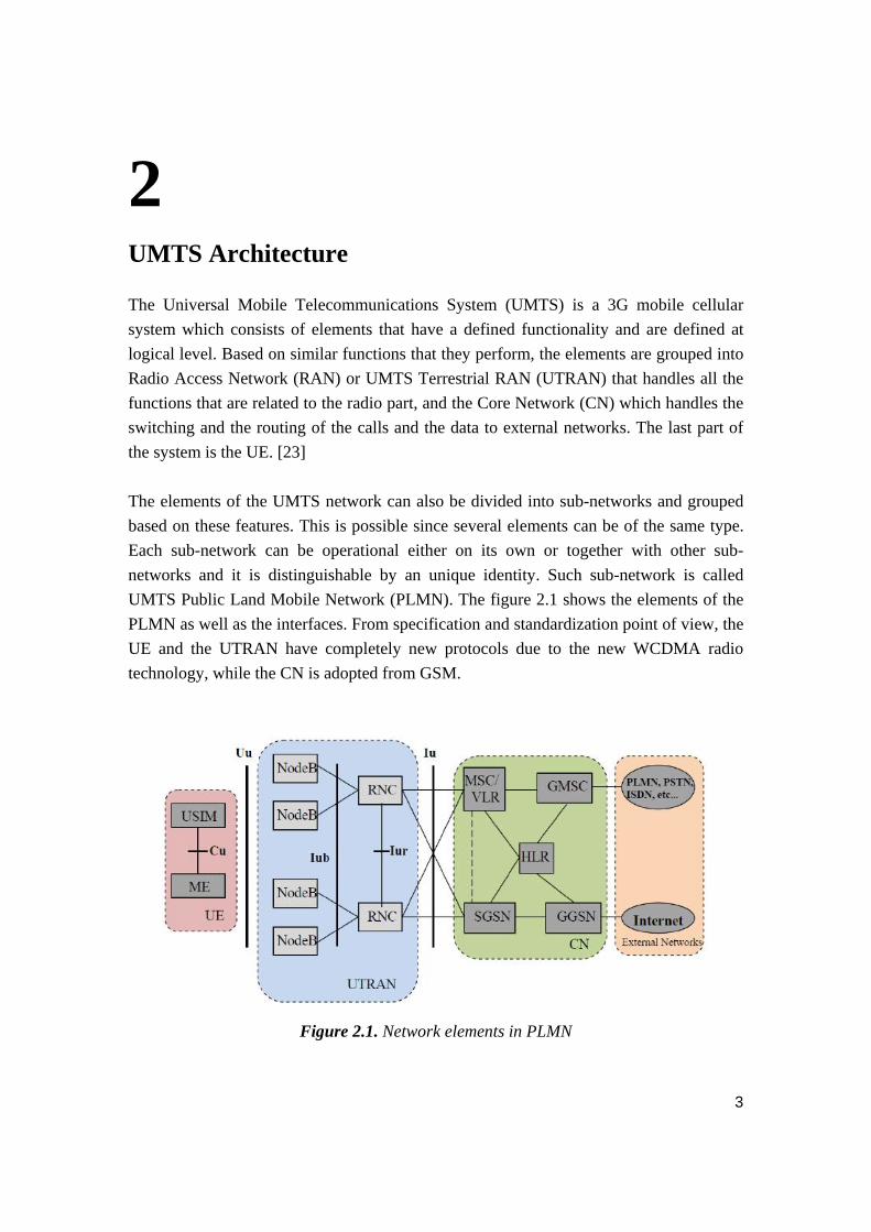
UMTS Public Land Mobile Network (PLMN). The figure 2.1 shows the elements of the
PLMN as well as the interfaces. From specification and standardization point of view, the
UE and the UTRAN have completely new protocols due to the new WCDMA radio
technology, while the CN is adopted from GSM.
Figure 2.1. Network elements in PLMN
UMTS Architecture
4
The UE has two parts:
‐ Mobile Equipment (ME) is the terminal used for radio communication over the Uu
interface.
‐ UMTS Subscriber Identity Module (USIM) is a smartcard which keeps the users
identity and performs authentication algorithms. It has the authentication and
encryption keys stored.
The UTRAN also has two elements:
‐ Node B is the node that communicates directly with the handset.
‐ Radio Network Controller (RNC) is the element that manages the radio resources.
It controls the Node Bs that are in its domain.
In the CN, these are the main elements:
‐ Home Location Register (HLR) is a database with the user’s service profile which
consists of information about allowed and forbidden services. This information
stays stored as long as the subscription is active.
‐ Mobile Services Switching Centre/Visitor Location Register (MSC/VLR) serves
the UE in its current position. The MSC is used to switch the CS transitions, while
the VLR has a copy of the visiting user’s service profile that are in its location
area.
‐ Gateway MSC (GMSC) is a gateway between two networks for CS services.
When the mobile switches networks during a call, the call has to pass through the
GMSC.
‐ Serving General Packet Radio Service (GPRS) Support Node (SGSN) is typically
used for PS services with similar functionalities to MSC/VLR.
‐ Gateway GPRS Support Node (GGSN) has a function similar to GMSC but for PS
services.
The external networks can be grouped as:
‐ CS networks provide circuit-switched connections.
‐ PS networks provide connections for packet data.
Speaking of the interfaces, these are the main open interfaces:
‐ Cu interface is the electrical interface between the USIM and the ME.
‐ Uu interface is the radio interface through which the UE communicates with the
Node B.

UMTS Architecture
5
‐ Iu interface connects UTRAN to CN.
‐ Iur interface allows soft handover between RNCs from different manufacturers.
‐ Iub interface is the connection between a Node B and a RNC.
2.1 UTRAN Architecture
The UTRAN is the part of the UMTS network that is of highest concern in this thesis
work, therefore it will be described in details.
UTRAN is a group of one or more Radio Network Sub-Systems (RNSs), where a RNS
consists of one RNC and one ore more Node Bs. If there is more than one RNC, they are
connected through the Iur interface among them; while the connection with the Node B is
via the Iub interface.
Radio Network Controller
The RNC handles the control of the radio resources of the UTRAN. It interfaces the CN
and terminates the RRC protocol as well. According to the logical functions of the RNC,
three types can be considered:
‐ Controlling RNC (CRNC);
‐ Serving RNC (SRNC);
‐ Drift RNC (DRNC).
If there is only one Node B that is connected to a certain RNC, this RNC is a CRNC of
that Node B. It is responsible to control the load and the congestion of the cells used by
the mobile, as well as for the admission control and code allocation. The SRNC
terminates the Iu link for user data transfer and also the corresponding RAN application
part (RANAP) signaling to/from the CN. It performs L2 processing of the data to and
from the radio interface. The RRM operations, like RAB parameters mapping, handover
decision etc, are also a role of the SRNC. The DRNC is in any RNC. It performs
transparent routing between the Iub and Iur interfaces, except when the UE uses a
common or shared transport channel.

UMTS Architecture
6
Node B
The Node performs the air interface L1 processing, such as channel coding and
interleaving, rate adaptation, spreading etc. Some of the RRM operations are also
performed by the Node B like inner loop power control.
The protocol structures for the UTRAN terrestrial interfaces are divided into horizontal
layers and vertical planes. The main layers are the Radio Network Layer and the
Transport Network Layer.
Figure 2.2. Protocol model for UTRAN interfaces
The vertical plane is divided into Control and User Plane. The control plane is used for
all the signaling part. It includes the application protocol and the signaling bearer for the
transport of the application protocol messages. The control plane in the transport network
layer is used for all the signaling in the transport layer and it doesn’t include any radio
network layer information. The transport network control plane allows complete
independence to the application protocol in the radio network control plane from the
technology selected for the data bearer in the user plane.

UMTS Architecture
7
The user plane is in charge of transporting all the information sent and received by the
user like coded voice or packets. The data streams and the data bearers for the data
streams are included in the user plane. In the transport network user plane are the data
bearers in the user plane and the signaling bearers for the application protocol. During
real-time operation, the data bearers in the transport network user plane are directly
controlled by the transport network control plane.
2.2 UTRAN Interfaces and Signaling The Iu interface, as mentioned before, is the connection between UTRAN and CN. It is
an open interface whose role is to deal with switching, routing and service control. The Iu
has two different instances for CS and PS services, and also an additional third instance
for BC (Broadcast) has been deployed for Cell Broadcast Services.
The main signaling protocol in Iu is the RANAP (Radio Access Network Application
Part) protocol. It contains all the control information intended for the radio network
layer. RANAP has many functions:
‐ Relocation and SRNS Relocation – handles SRNS relocation from one RNS to
another without changing the radio resources, and hard handover;
‐ Inter-RNS hard handover – for relocation of the SRNS functionality from one
RNS to another and changing the radio resources;
‐ RAB management, RAB Setup, modification of the characteristics of a existing
RAB, clearing an existing RAB, including the RAN-initiated case;
‐ Iu release – releases all the resources related to a specified UE;
‐ Reporting unsuccessfully transmitted data;
‐ Common ID management – identification of the UE is sent to the UTRAN to
allow coordinated paging from two different CN;
‐ Paging – CN pages an UE which is in Idle state for a service request;
‐ Management of tracing – the CN is asking to the UTRAN to record all the activity
in a given connection between some UE and the UTRAN;
‐ UE-CN signaling transfer – transparent transfer of UE-CN signaling messages;
‐ Transfer of the first UE message from UTRAN to UE - initiates the signaling
connection for the Iu;
‐ Direct transfer – transfer of all the signaling messages over the Iu both in
downlink and uplink;

UMTS Architecture
8
‐ Security rode control – to set the ciphering or integrity checking on or off;
‐ Management of overload – a simple mechanism is applied to control the load over
Iu;
‐ Reset – used in error situations to reset the CN or the UTRAN side of the Iu;
‐ Location reporting.
The Iur Interface (RNC–RNC Interface) was initially designed to support the soft
handover between two RNCs, but later on more features were added. The signaling
protocol in the Iur interface, the RNSAP (Radio Network Subsystem Application Part)
protocol has four different groups of procedures i.e. four modes due to the four different
functionalities connected to the Iur interface. The modes, followed by the main functions
are listed below.
Iur1: Support of the Basic Inter-RNC Mobility
‐ Support of SRNC relocation;
‐ Support of inter-RNC cell and UTRAN registration area update;
‐ Support of inter-RNC packet paging;
‐ Reporting of protocol errors.
Iur2: Support of Dedicated Channel Traffic
‐ Establishment, modification and release of the dedicated and shared
channel in the DRNC due to handovers in the dedicated channel state;
‐ Setup and release of dedicated transport connections across the Iur
interface
‐ Transfer of DCH Transport Blocks between SRNC and DRNC;
‐ Management of the radio links in the DRNS, via dedicated measurement
report procedures, power setting procedures and compress mode control
procedures.
Iur3: Support of Common Channel Traffic
‐ Setup and release of the transport connection over Iur for common
streams;
‐ Flow control between the MAC-d and MAC-c;
‐ Splitting of the MAC layer between the SRNC (MAC-d) and the DRNC
(MAC-c). The scheduling for downlink data transmission is performed in
the DRNC.

UMTS Architecture
9
Iur4: Support of Global Resource Management
‐ Transfer of cell information and measurements between two RNCs;
‐ Transfer of positioning parameters between controller;
‐ Transfer of Node B timing information between two RNCs.
The Iub Interface (RNC–Node B Interface) i.e. the NBAP (Node B Application Part)
signaling can be divided in two important components:
Common NBAP (C-NBAP), which defines the signaling procedures across the
common signaling link, controls the overall Node B functionality:
‐ Setup of the first radio link of one UE and selection of the traffic termination
point;
‐ Cell configuration;
‐ Handling of the RACH/FACH/CPCH and PCH channels;
‐ Initialization and reporting of Cell or Node B specific measurement;
‐ Location Measurement Unit (LMU) control;
‐ Fault management.
Dedicated NBAP (D-NBAP), for the signaling in the dedicated signaling link,
controls radio links for a specific UE:
‐ Addition, release and reconfiguration of radio links for one UE context;
‐ Handling of dedicated and shared channels;
‐ Handling of softer combining;
‐ Initialization and reporting of radio-link-specific measurement;
‐ Radio-link fault management.

10
3 Transport Channels
The data in the UMTS Terrestrial Radio Network that are generated at higher layers are
being carried over the air by transport channels that are mapped on certain physical
channels at the physical layer, which should be able to support variable bit-rate transport
channels so that bandwidth-on-demand services could be offered.
3.1 Dedicated Transport Channel
The Dedicated Channel (DCH) is the only dedicated transport channel which handles
information transfer for a particular UE, both the actual data, such as speech, and the
higher layer control information, like handover commands or measurement reports. This
content on the DCH cannot be seen by the physical layer, thus they have the same
treatment. With the WCDMA, there is no need of separate transport channel since
variable bit rate is supported as well as service multiplexing. Some of the characteristics
of DCH are:
- Shorter TTI, leading to faster link adaptation;
- HARQ (forward error correction added to error detection) with incremented
redundancy, leading to more effective transfer;
- Power control;
- Soft handover support;
- Spreading code assigned per user;
- Max DL data rate: 384 kbps.
3.2 Common Transport Channels
There are six different common transport channel types. They don’t have soft handover,
but some of them have fast power control.

Transport Channels
11
Broadcast Channel (BCH) transports information that is specific for the UTRA or
for some specific cell, such as random access codes and slots, or types of transmit
diversity methods. In order to reach all the users in an area, this channel is
transmitted with high power.
Forward Access Channel (FACH) is a downlink transport channel which brings
control information to the UE registered on the system, and can also be used for
transmitting packets. These are the characteristics of the FACH:
- No power control;
- Common spreading code;
- There might be more than one FACH per cell;
- Low data rate: 30 kbps.
Paging Channel (PCH) is a downlink transport channel carrying the data
important for the paging procedure, meaning the information when the network
tries to start a communication with the UE. The same paging message can be sent
in up to hundred cells. The terminals have to be able to receive the paging
information in the whole cell area.
Random Access Channel (RACH) is an uplink transport channel which carries
control information from the UE, and it can also be used to transmit small data
packets. The whole cell area has to hear the RACH, meaning that the practical
data rates have to be low.
Downlink Shared Channel (DSCH) is carrying dedicated user data and/or control
information and it can be shared by several users. It is similar to FACH with the
difference that it uses fast power control and variable bit rate. It is not needed to
be heart in the whole cell area. It is always associated with a downlink DCH.
DSCH was further replaced with HSDPA, which will be discussed in the next
chapter.
12
4 HSPA and HSPA+ High Speed Packet Access (HSPA) is the enhancement of the performances of the
WCDMA technology. With HSPA higher rates in both downlink and uplink can be
reached, 14 Mbps and 5.76 Mbps respectively. The latency is smaller and system
capacity is increased while the production cost is reduced. It consists of two mobile
telephony protocols, HSDPA and HSUPA.
4.1 HSDPA
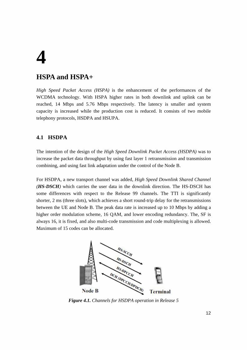
The intention of the design of the High Speed Downlink Packet Access (HSDPA) was to
increase the packet data throughput by using fast layer 1 retransmission and transmission
combining, and using fast link adaptation under the control of the Node B.
For HSDPA, a new transport channel was added, High Speed Downlink Shared Channel
(HS-DSCH) which carries the user data in the downlink direction. The HS-DSCH has
some differences with respect to the Release 99 channels. The TTI is significantly
shorter, 2 ms (three slots), which achieves a short round-trip delay for the retransmissions
between the UE and Node B. The peak data rate is increased up to 10 Mbps by adding a
higher order modulation scheme, 16 QAM, and lower encoding redundancy. The, SF is
always 16, it is fixed, and also multi-code transmission and code multiplexing is allowed.
Maximum of 15 codes can be allocated.
Figure 4.1. Channels for HSDPA operation in Release 5
HSPA and HSPA+
13
HS-DSCH was implemented with the introduction of three new physical channels:
The High Speed Shared Control Channel (HS-SCCH) tells to the user that the
data will be sent on the HS-DSCH. It carries the necessary control information to
enable decoding of the data on HS-DSCH and to perform the possible physical
layer combining of the data sent on HS-DSCH in case of retransmission or a
packet with an error. A number of HS-SCCHs should be allocated that correspond
to the maximum number of users that will be code-multiplexed. It is not necessary
to transmit the HS-SCCH if there is no data on the HS-DSCH.
The High Speed Dedicated Physical Control Channel (HS-DPCCH) transports
acknowledgement information (both ACK and NACK) uplink to reflect the
results of the CRC check, and the current channel quality indicator (CQI)
downlink, to indicate the estimated transport block size, modulation type and
number of parallel codes that can be received correctly.
The High Speed Physical Downlink Shared Channel (HS-PDSCH) is mapped to
the HS-DSCH which carries the actual data.
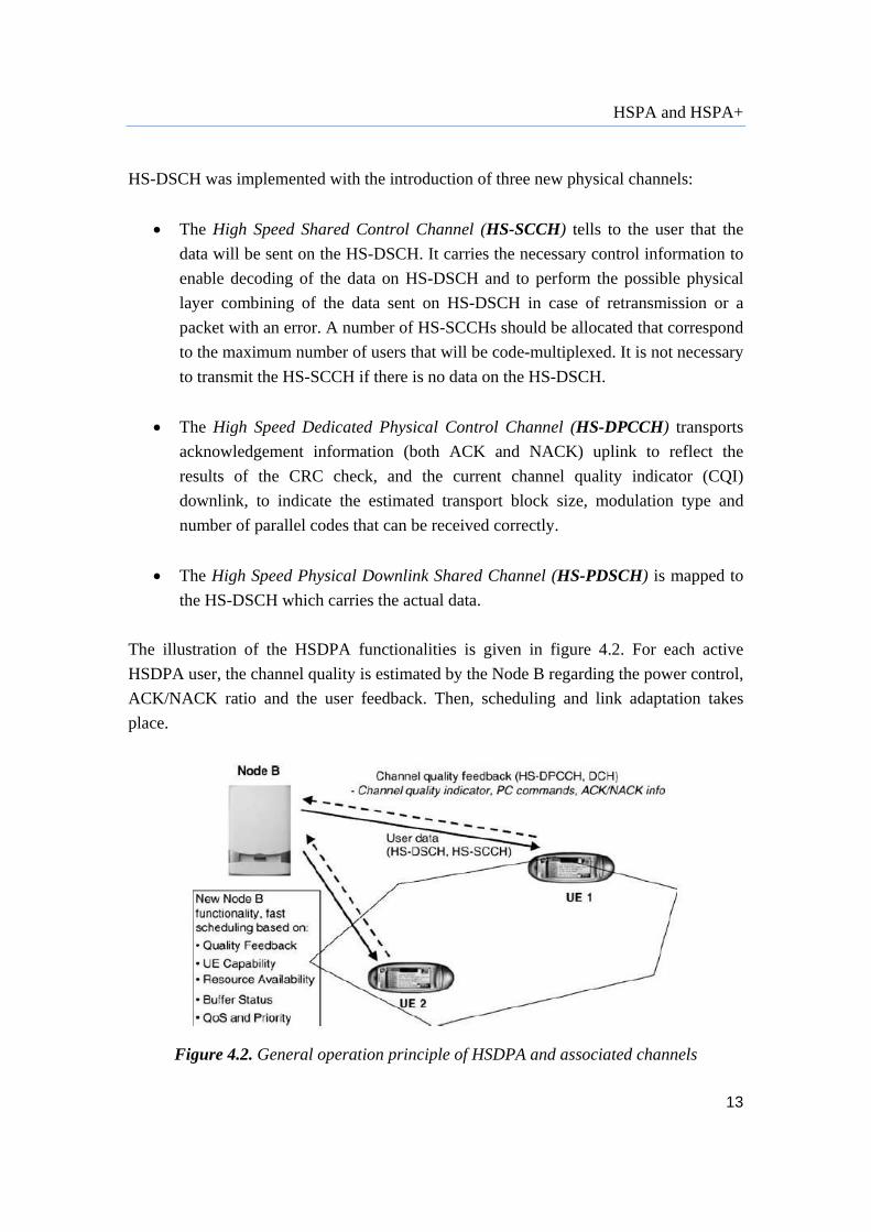
The illustration of the HSDPA functionalities is given in figure 4.2. For each active
HSDPA user, the channel quality is estimated by the Node B regarding the power control,
ACK/NACK ratio and the user feedback. Then, scheduling and link adaptation takes
place.
Figure 4.2. General operation principle of HSDPA and associated channels
HSPA and HSPA+
14
The fundamental features of WCDMA, variable spreading factor and fast power control
do not exist anymore with HSDPA. On that expense, adaptive modulation and coding
(AMC), extensive multi-code operation and a fast and spectrally efficient retransmission
strategy (HARQ) were added. Another change is that the scheduling decisions are given
to the Node B. HSDPA enables a scheduling such that most of the cell capacity is
allocated to one user for a very short time, if requested, when there are good conditions.
With the packet combining diversity gain is achieved as well as an improvement of the
decoding efficiency, since the received data packets are stored and then they are
combined with the new transmission.
Summed up, these are the main improvement in HSDPA:
- Data rate up to 14.4 Mbps;
- Shared channel transmission;
- No fast power control;
- No variable spreading codes (only SF=16);
- No soft handover;
- Time and code multiplexing;
- Adaptive modulation and coding, leading to rate control;
- Fast retransmission/scheduling;
- Short TTI = 2ms;
- The same set of codes and power is time shared among multiple users (up
to 15 codes).
4.2 HSUPA HSUPA was introduced to deliver similar favors for the uplink as the HSDPA did for the
downlink. So the improvements were made mainly to make the uplink packet data
performance better by using HARQ and Node B controlled scheduling. From the Release
99 uplink channels, only DCH and RACH were kept in Release 5 and onwards. Since
RACH is usable only in Cell_FACH state for sending limited amount of data, the only
channel discussed will be DCH, known as E-DCH.
The Enhanced Dedicated Channel (E-DCH) is used for any type of service. Conversely
from HSDPA, E-DCH has dynamically variable spreading factor, uses power control and
can supports soft handover. The main things for increasing the packet data throughput are
the extensive multi-code operation together with the Node B scheduling, and the fast
HSPA and HSPA+
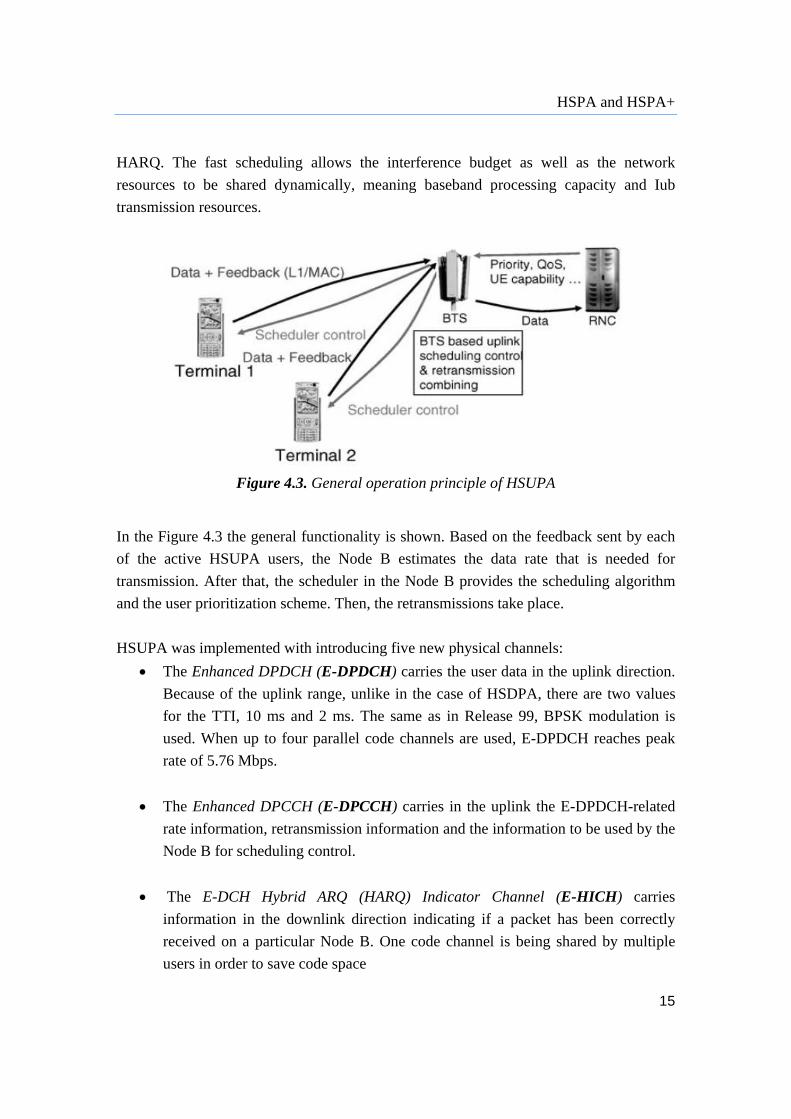
15
HARQ. The fast scheduling allows the interference budget as well as the network
resources to be shared dynamically, meaning baseband processing capacity and Iub
transmission resources.
Figure 4.3. General operation principle of HSUPA
In the Figure 4.3 the general functionality is shown. Based on the feedback sent by each
of the active HSUPA users, the Node B estimates the data rate that is needed for
transmission. After that, the scheduler in the Node B provides the scheduling algorithm
and the user prioritization scheme. Then, the retransmissions take place.
HSUPA was implemented with introducing five new physical channels:
The Enhanced DPDCH (E-DPDCH) carries the user data in the uplink direction.
Because of the uplink range, unlike in the case of HSDPA, there are two values
for the TTI, 10 ms and 2 ms. The same as in Release 99, BPSK modulation is
used. When up to four parallel code channels are used, E-DPDCH reaches peak
rate of 5.76 Mbps.
The Enhanced DPCCH (E-DPCCH) carries in the uplink the E-DPDCH-related
rate information, retransmission information and the information to be used by the
Node B for scheduling control.
The E-DCH Hybrid ARQ (HARQ) Indicator Channel (E-HICH) carries
information in the downlink direction indicating if a packet has been correctly
received on a particular Node B. One code channel is being shared by multiple
users in order to save code space

HSPA and HSPA+
16
The E-DCH Absolute Grant Channel (E-AGCH) and E-DCH Relative Grant
Channel (ERGCH) carry the Node B scheduling control information in order to
control the uplink transmission rate.
4.3 HSPA+
The objective of HSPA+ is to improve the HSPA based radio networks regarding to
spectrum efficiency, peak data rate and latency. HSPA+ enhances the performance of
HSPA networks, and having the increased demand for high-performance mobile
broadband services with the new data applications, it enables wireless operators to
continue satisfying these data needs in the most economical way, as HSPA+ doubles the
data capacity compared to HSPA Release 6. [7]
There are many important features that will be presented further on to make it clear why
HSPA+ made an evolution in the radio network.
The first very significant feature is the deployment of the MIMO technology, which
represents a system with multiple input and multiple output signals. That means that there
are multiple antennas both at the transmitter and the receiver side so that the spatial
dimension of the radio channel is efficiently used. In the downlink, the introduction of
MIMO increases the throughput and the data rate, which theoretically reaches up to 28
Mbps. Uplink MIMO is not supported. [9]
Figure 4.4. Evolution with MIMO

HSPA and HSPA+
17
Second, HSPA+ uses higher order modulation. The possibility of using 64QAM in
downlink and 16QAM in uplink, leads to pick data rates of 21 Mbps and 11.5 Mbps
respectively.
What optimizes the support of the packet data services in the high speed network is the
Continuous Packet Connectivity (CPC). The connections of the packet data users has to
be maintained since large number of users, which stay connected longer period of time,
are being supported in a cell, although these users may only occasionally have active
periods of transmissions. Thus, to minimize the latency, connection termination and re-
establishment must be avoided. The maintaining means that the control channels in both
uplink and downlink have to be supported which leads to augmentation of overhead; the
uplink control channels (DPCCH and HS-DPCCH) contribute to the overall uplink noise
raise, while the downlink control channel (HS-SCCH) causes increased battery
consumption. So, one of the aims of CPC is to reduce the overhead. [8]
Some of the features that are introduced to resolve this issue are:
Uplink Discontinuous Transmission (DTX) – allows the UE to stop the
transmission on DPCCH if there is no activity on E-DCH or HS-DPCCH.
E-DCH Tx start time restrictions – allows the Node B to restrict the points of
transmission for a certain UE, meaning that the UE can transmit only on pre-
defined instants.
Downlink Discontinuous Reception (DRX) – allows the network to limit the
number of subframes in which the UE has to monitor the HS-SCCH, for finding
out the possible downlink data allocations, in order to reduce the battery
consumption of the UE.
HS-SCCH less operation – for small packet services.
HS-SCCH orders – they tell to the UE if DRX, DTX or HS-SCCH less operation
should be enabled or disabled.
New Uplink DPCCH slot format – contains only six pilot bits and four TPC bits.

HSPA and HSPA+
18
Enhanced Fractional DPCH (F-DPCH) – allows code sharing between HSDPA
data users.
Further on, in order to support the high data rates that were enabled from MIMO and
higher order modulation, some layer 2 modifications in downlink were also inevitable,
including both the MAC and the RLC protocol. Namely, in HSPA+, flexible RLC PDU
sizes are supported and multiplexing of data belonging to several priority queues into one
TTI is allowed.
Figure 4.5. Flexible RLC PDU size operation
HSPA+ has also introduced an enhanced Cell_FACH state (downlink). Not like the
release 99, where the FACH mapped on S-SSPCH was used for small packets, now the
HS-DSCH on HS-PDSCH in Cell_FACH state is preferred. This increases the data rate in
Cell_FACH state and also the signaling delays of the control messages are reduced
because of the shorter TTI.
The improvements that were mentioned till now were considering the Release 7. In
release 8 there are some more features added.
To increase the throughput of the user even more when the radio conditions are very well,
the combination of 64QAM and MIMO was introduced. This allows maximum rate of
even 42Mbps.

HSPA and HSPA+
19
Next, CS over HSPA is allowed. Namely, we are not talking about VoIP, but circuit
telephony with a wireless IP transport. Both AMR and AMR wideband is supported.
To provide even better user experience in the cell, allowing a dual cell HSDPA operation
gives a chance of network recourse pooling which helps a lot in the cases when some
techniques (e.g. MIMO) cannot be used. The two cells belong to the same Node B and
are on adjacent carriers. Both work in the same frequency band.
Figure 4.6. Dual Cell HSDPA operation
As an analogy to the downlink, similar changes were done in the uplink as well. Namely,
Layer 2 improvements in uplink were also made; flexible RLC PDU sizes are supported
as well as segmentation/reassembly was allowed. Also, enhanced uplink for Cell_FACH
state was introduced. For this feature to be supported, a new common transport channel
E-DCH was specified which is used for transmitting in uplink. This channel is shared
between UE who have individual codes.
Furthermore, Release 8 introduces HS-DSCH DRX reception in Cell_FACH which gives
an improvement in terms of battery consumption when there is infrequent small packet
data services.
Another feature is the HSPA VoIP to WCDMA/GSM CS continuity, allowing an efficient
way of switching from a VoIP call to a WCDMA or GSM CS call while the UE is in a
connected mode. For this reason, a Single Radio Voice Call Continuity (SRVCC)
mechanism was specified which handles session transfers of the voice component within
a PS bearer to the CS domain.
HSPA and HSPA+
20
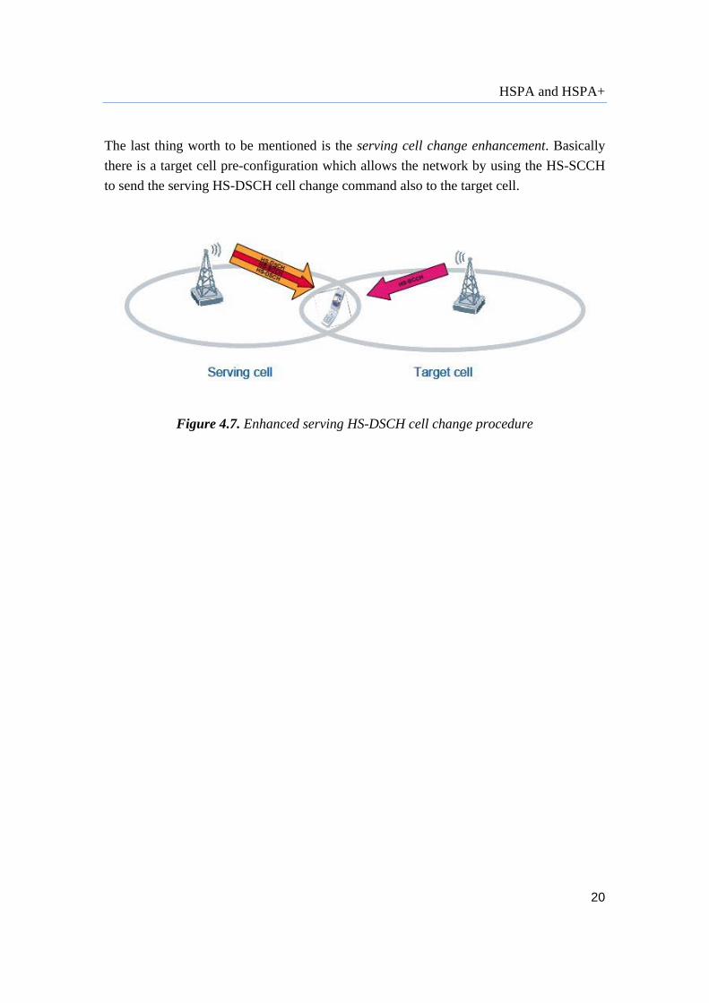
The last thing worth to be mentioned is the serving cell change enhancement. Basically
there is a target cell pre-configuration which allows the network by using the HS-SCCH
to send the serving HS-DSCH cell change command also to the target cell.
Figure 4.7. Enhanced serving HS-DSCH cell change procedure

21
5 Radio Resource Management
Moving to HSDPA and HSUPA not only the user experience was changed, but also the
managing of the radio resources has undergone some changes. The role of a scheduler
was taken from the RNC and given to the Node B, using adaptive coding and modulation
which leads to an effective rate control. Also the retransmission task was transferred from
the RNC to the Node B, introducing HARQ. Another change that was not having soft
handovers for HSDPA data, so there is no more need of utilizing multiple Iub and Iur
interfaces. The roles of each element in the UMTS network are given in the figure below.
Figure 5.1. HSDPA and HSUPA RRM architecture in Release 6
The architecture can be divided in user and control plane. The control plane handles the
user data in terms of Erlangs and Mbps, while the control plane is handling all the
signaling related to configuring the channels, mobility management etc. The radio link
control RLC is the one that manages the segmentation and retransmission for both the
user and control data. [5] Three different modes of RLC are applicable:
Transparent mode: not applicable when HSDPA/HSUPA is used; used for AMR
speech

Radio Resource Management
22
Unacknowledged mode: when there are no retransmissions; in the case of VoIP.
Acknowledged mode: when there are ensured retransmission, required all the
packets to be delivered.
In the HSDPA user plane a new protocol entity was introduced, MAC-hs (for high speed)
which is in charge of the scheduling and the priority handling. With HSUPA there is new
MAC entity as well, MAC-es/e, based on the control information from the RNC and the
capacity request from the UE. The main task of the new MAC-es is to ensure that the
packets received in different Node Bs, in the case of soft handover to be provided in the
correct order. Conversely, in the HSUPA the RLC layer doesn’t succeed to deliver the
packets correctly after an excess of the maximum number of retransmissions.
Figure 5.2. HSDPA flow control on the Iub interface
Speaking of the air interfaces, the buffering in the Node B, together with the scheduler,
allows a pick rate as high as the terminal and the Node be are capable to reach, keeping
the maximum bit rate over the Iub/Iup with retaining the QoS parameters received by the
packet core. This also requires flow control, to keep the buffer from overflow. This way
the user gets more resources under good radio conditions. In the previous image the flow
control is shown.
Radio Resource Management
23
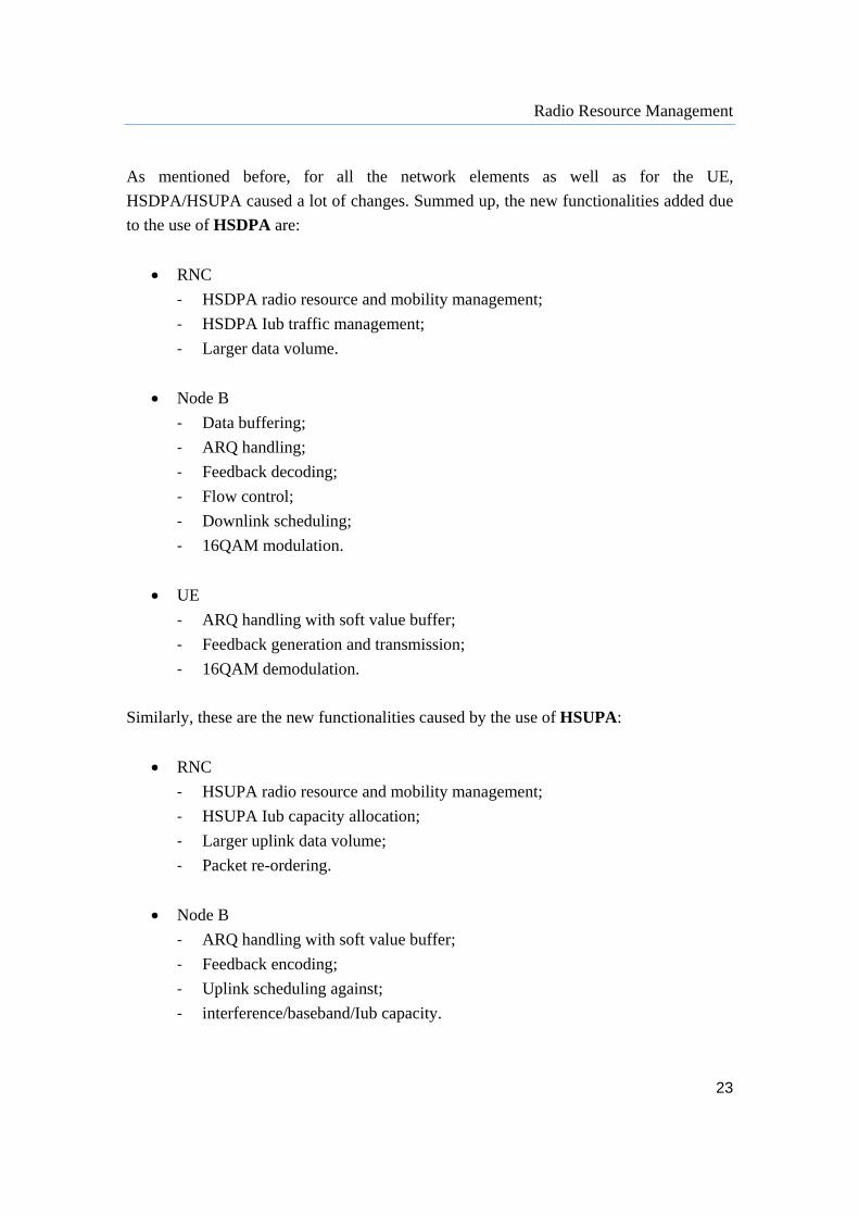
As mentioned before, for all the network elements as well as for the UE,
HSDPA/HSUPA caused a lot of changes. Summed up, the new functionalities added due
to the use of HSDPA are:
RNC
‐ HSDPA radio resource and mobility management;
‐ HSDPA Iub traffic management;
‐ Larger data volume.
Node B
‐ Data buffering;
‐ ARQ handling;
‐ Feedback decoding;
‐ Flow control;
‐ Downlink scheduling;
‐ 16QAM modulation.
UE
‐ ARQ handling with soft value buffer;
‐ Feedback generation and transmission;
‐ 16QAM demodulation.
Similarly, these are the new functionalities caused by the use of HSUPA:
RNC
‐ HSUPA radio resource and mobility management;
‐ HSUPA Iub capacity allocation;
‐ Larger uplink data volume;
‐ Packet re-ordering.
Node B
‐ ARQ handling with soft value buffer;
‐ Feedback encoding;
‐ Uplink scheduling against;
‐ interference/baseband/Iub capacity.
Radio Resource Management
24
UE
‐ ARQ handling;
‐ TX power and buffer status feedback;
‐ generation and transmission;
‐ Multicode transmission;
‐ Uplink scheduling.
The major part of the control signaling between UE and UTRAN is radio resource control
(RRC) messages which are carrying all the necessary parameters to set up, modify and
release layer 2 and layer 1 protocol entities. They also carry all higher layer signaling
messages like mobility management, connection management, session management. Also
the mobility of the UE while it is connected is controlled by the RRC signaling
(measurements, handovers, cell updates).
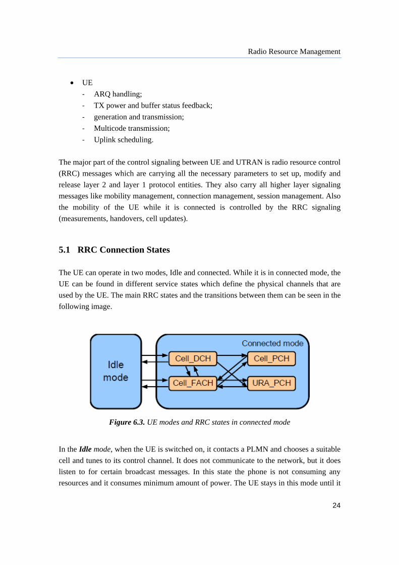
5.1 RRC Connection States
The UE can operate in two modes, Idle and connected. While it is in connected mode, the
UE can be found in different service states which define the physical channels that are
used by the UE. The main RRC states and the transitions between them can be seen in the
following image.
Figure 6.3. UE modes and RRC states in connected mode In the Idle mode, when the UE is switched on, it contacts a PLMN and chooses a suitable
cell and tunes to its control channel. It does not communicate to the network, but it does
listen to for certain broadcast messages. In this state the phone is not consuming any
resources and it consumes minimum amount of power. The UE stays in this mode until it

Radio Resource Management
25
requests a RRC connection. The UTRAN can only address all the UEs in a cell or all the
UEs that are monitoring.
In the Cell_DCH state, the UE is allocated a dedicated physical channel and the UE is
known by its serving RNC. According to the measurement control information that was
sent to the UE from the RNC, the UE sends measurement reports for the measurements it
performs. The UE consumes the most resources from the network in this mode, both
RNC processing and air interfaces, but also the battery waist is at highest level.
In the Cell_FACH state, there is no dedicated physical channel assigned to the EU,
instead, RACHs and FACHs are used for carrying both signaling messages and small
data. So, the phone communicates with the network by shared channel and the RNC
knows the location of the phone. The UE performs cell reselection, and in order to inform
the RNC about its location on a cell level, it sends Cell Update message to the RNC.
Thus, the UE uses the network resources in terms of the capacity of the air interfaces and
also in terms of RNC processing power. In this state small bits of data can be transmitted
at a relatively low rate. What’s more, the UE shares the forward and access channels with
other devices meaning that the amount of data that can be processed depends on the load
of the common channel. In Cell_FACH the power consumption is much higher.
In the Cell_PCH state, the serving RNC knows where the UE is located in the network,
but the UE can only be reached via PCH, whose monitoring is performed with a
discontinuous reception (DRX) functionality which saves the battery of the UE. The UE
listens to the BCH for some critical information, but since it is a shared channel, an
additional phone in Cell_PCH state doesn’t have any impact on the network, so the there
is small current consumption.
The URA_PCH state is very similar to the Cell_PCH with the difference that the UE tells
its location to the SRNC only if the UTRAN Registration Area (URA) changes, and not
after every reselection. This is similar to the Cell Update procedure and it’s called URA
Update Procedure. A cell can belong to one or more URAs, so the UE performs URA
Update Procedure just when the UE cannot find the latest URA identification from the
list of URAs read from the BCH.
If the RRC connection experiences failure or the RRC connection is released, the UE
returns to the Idle mode.

26
6 Smartphones
The number of the smart devices is constantly growing and it is a lot higher than the
active mobile broadband-enabled laptops. According to the Nokia Siemens Network
experts, by the year 2015 over 85% of the traffic in the mobile networks worldwide will
be generated by mobile data, 49% of which will be via handheld devices. [17] Therefore,
it is pretty logical the operators and vendors to turn their attention to the smartphones and
do some analysis in this field in order to provide good quality of the service to the
customers. We did an investigation about this issue in the Vodafone network for the last
one and a half year, and the numbers show a rapid growth of the smartphones, while the
number of the Vodafone Internet Keys (VIKs) doesn’t change much.
VIK Smartphone
Figure 6.1. Growth of VIKs and smartphones in the last one and a half year
The rapidly increasing number of smartphones in the network has given a great challenge
to the operators. Thus, todays’ network should not only satisfy the laptop users that
require high data traffic, but also to make the smartphone users happy who are keen on
establishing lots of connections per day. Some market researches show that an average
smartphone consumes only 10% of the data traffic that a laptop does. So, the throughput
is no longer the challenge, but there is a new aspect the operators have to focus on – the
number of simultaneous connections.

Smartphones
27
In the beginning when the number of smartphones in the network was relatively low,
operators didn’t experience any problem and there was nothing to worry about. But, as
soon as the number of smartphones started to constantly increase, the customers started to
complain about the poor data performance and the poor battery life. Why would this be
happening? Apparently because laptops and smartphones have a different behavior in the
network.
6.1 Understanding smartphones behavior
Using the smartphones, two kinds of traffic are generated in the network. There is the
data traffic that is carrying the information interesting for the user, and the signaling
traffic, the language that all the network elements use. The later is the one that the
smartphones are generating more and the one that the networks were not built to handle.
Having in mind that the smartphone trend is still going to rise, a shift of the attention
should be expected from volume and throughput to connections and signaling.
We tried to see how the smartphones and the laptops are behaving in the network of
Vodafone Italy from the side of the both types of traffic starting from 2010 onwards. The
results have proved our expectations. Since the smartphones are usually connected 24
hours a day, they generate more control plane traffic to keep the applications alive and
therefore it is more likely to have a big amount of smartphones active in the network (see
image 6.2). But in the same time all of them carry a small amount of data (see image 6.3).
Figure 6.2. Peak PDP context per month for smartphones
and laptops in Vodafone Italy
2010
2011
2012
Peak PDP Context/monthDongles and datacard
Smartphone
Smartphones
28
2010
2011
2012
Mln Mbyte /month
Dongles and datacard
Smartphone
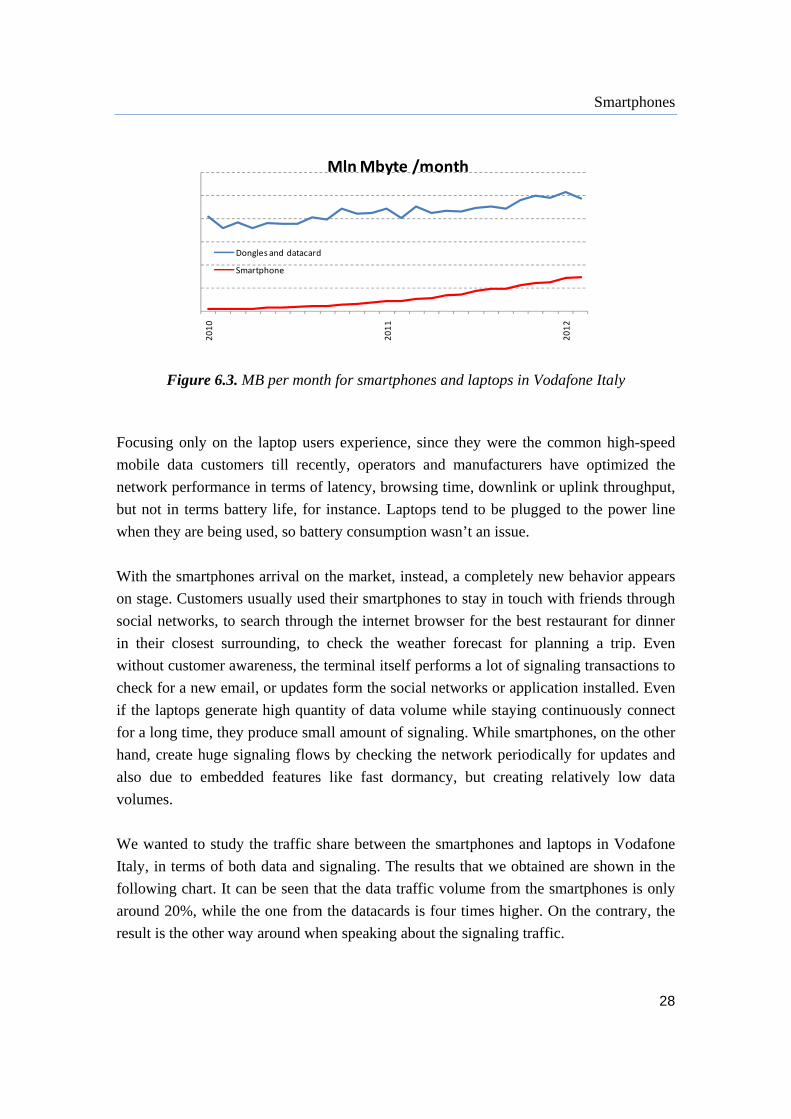
Figure 6.3. MB per month for smartphones and laptops in Vodafone Italy
Focusing only on the laptop users experience, since they were the common high-speed
mobile data customers till recently, operators and manufacturers have optimized the
network performance in terms of latency, browsing time, downlink or uplink throughput,
but not in terms battery life, for instance. Laptops tend to be plugged to the power line
when they are being used, so battery consumption wasn’t an issue.
With the smartphones arrival on the market, instead, a completely new behavior appears
on stage. Customers usually used their smartphones to stay in touch with friends through
social networks, to search through the internet browser for the best restaurant for dinner
in their closest surrounding, to check the weather forecast for planning a trip. Even
without customer awareness, the terminal itself performs a lot of signaling transactions to
check for a new email, or updates form the social networks or application installed. Even
if the laptops generate high quantity of data volume while staying continuously connect
for a long time, they produce small amount of signaling. While smartphones, on the other
hand, create huge signaling flows by checking the network periodically for updates and
also due to embedded features like fast dormancy, but creating relatively low data
volumes.
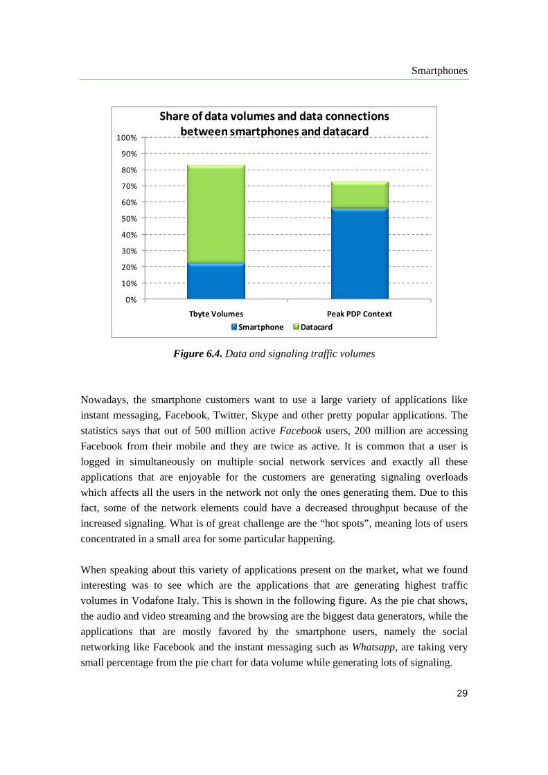
We wanted to study the traffic share between the smartphones and laptops in Vodafone
Italy, in terms of both data and signaling. The results that we obtained are shown in the
following chart. It can be seen that the data traffic volume from the smartphones is only
around 20%, while the one from the datacards is four times higher. On the contrary, the
result is the other way around when speaking about the signaling traffic.
Smartphones
29
0%
10%
20%
30%
40%
50%
60%
70%
80%
90%
100%
Tbyte Volumes Peak PDP Context
Share of data volumes and data connections between smartphones and datacard
Smartphone Datacard
Figure 6.4. Data and signaling traffic volumes
Nowadays, the smartphone customers want to use a large variety of applications like
instant messaging, Facebook, Twitter, Skype and other pretty popular applications. The
statistics says that out of 500 million active Facebook users, 200 million are accessing
Facebook from their mobile and they are twice as active. It is common that a user is
logged in simultaneously on multiple social network services and exactly all these
applications that are enjoyable for the customers are generating signaling overloads
which affects all the users in the network not only the ones generating them. Due to this
fact, some of the network elements could have a decreased throughput because of the
increased signaling. What is of great challenge are the “hot spots”, meaning lots of users
concentrated in a small area for some particular happening.
When speaking about this variety of applications present on the market, what we found
interesting was to see which are the applications that are generating highest traffic
volumes in Vodafone Italy. This is shown in the following figure. As the pie chat shows,
the audio and video streaming and the browsing are the biggest data generators, while the
applications that are mostly favored by the smartphone users, namely the social
networking like Facebook and the instant messaging such as Whatsapp, are taking very
small percentage from the pie chart for data volume while generating lots of signaling.

Smartphones
30
Streaming Video & Audio
Browsing
File Transfer & P2P
Store
Social (Facebook & Twitter)
Minor & Other (SSL)
Mail Maps & Flickr
IM App (Facebook & WhatsApp)
Streaming Video & Audio
Browsing
File Transfer & P2P
Store
Social (Facebook & Twitter)
Minor & Other (SSL)
Maps & Flickr
IM App (Facebook & WhatsApp)
Cloud
VOIP
Games
Figure 6.5. Data traffic share from different applications
These applications generate small amount of data (ex. an usual IM has 1-2kB of data),
but any time that a message or update is done, there is signaling traffic equal to the one
needed to set up or break a voice call or larger data session. Moreover, the IM sessions,
consisting of back and forth messages, sometimes involve group of friends which leads to
a multiplicative effect from the signaling point of view. The IMS chat and other
persistent TCP based application like Push Mail apply periodic exchange of messages
between client and server so that the TCP connection is kept alive. When the user runs
multiple applications of this kind on his smartphone, it is really very difficult to predict
the overall periodicity of message exchange between network and smartphone and the
timer depends on the application synchronization needs. This should be solved with the
HSPA+ DRX feature mentioned before.[2]
Moreover, the mobile online gaming is becoming more and more popular. The users that
are attached to Internet gaming are now able to play the same games on their smartphone
that has a processor powerful enough to support that. This is another huge signaling
generator. From one side, the laptop gaming has more ads, leading to even higher data
traffic, around two times the one from the smartphones. And from another side, the
laptop gaming uses far less individual data connections, generating around one tenth of
the signaling provided by the smarphone gaming.

Smartphones
31
6.1.1 Always-On-Line Applications With the smartphones the users want to access the Internet and to get up-to-date
information anywhere and everywhere they want. Consequently this requires always-on-
line connection between the client and the server. For this connection to be maintained,
frequent periodical heartbeat packets have to be send. These packets are called keep-alive
messages that are used to keep the TCP connection when there are no messages to be
exchanged between the network and the smartphone. They are short and frequent and are
one of the main components of the background traffic. They consist of nearly 150 bytes
data and 6-7s connection time, but the amount of signaling traffic that is being generated
is large. These messages occur any time the application is active, which for most
applications means the whole day. The main interaction technologies are listed below. [4]
Pull/Polling – the initial request for data is done by the client and then the server
gives a respond to it immediately
Long-polling – the client ask for information from the server who keeps the
request open until there is some information available
Push – when there is any new information the server notifies the client directly
Mostly, the mobile application use polling, but the same application can be implemented
with different technology on different platforms and have different heartbeat
characteristics. This is shown in the table 6.1 (source: Huawei Smart Lab).
Table 6.1. Interaction technologies used for different applications on different platform
Platform Application Pull/Polling Long‐polling Push
iPhone Twitter 50s/205s
Facebook 5 to 60s
APNS 10~15min
HTC Android Twitter 5min
Facebook 30m/1H/2H/4H/Never
Google Talk 40 to 60min
Nokia
Symbian
Nimbuzz 2min 39s
Messaging 5 to 30min

Smartphones
32
Being the most popular application among users and generating lots of keep-alive
messages to provide the status updates as they occur, we wanted to see what is going on
in the network (Vodafone Italy) in the case of running a social network application, from
both data and signaling point of view. What we obtained was the following chart (image
6.6). When speaking about data volume (expressed in TB), there is two times higher
traffic in favor of the datacards. On the contrary, in the case of the signaling, around five
times more signaling traffic is generated from the smartphones.
Tbyte Volumes Peak PDP Context
Data volume and connections for Social Network application
Smartphone Datacard
Figure 6.6. Data traffic and signaling generated for smartphones and laptops
when using a social network application
6.1.2 Always-On-Line PDP Context Having always-on-line application obviously requires always-on-line PDP context, which
contains the subscriber's session information when the subscriber has an active session.
The always-on-line PDP context means that there are less PDP activation attempts, but
there is a high possibility of more Iu signaling traffic like paging, service request and Iu
release. It also requires from the network to have more IP addresses since one IP address
could be taken for a longer period. The keep-alive messages help this issue because of the
presence of the NATs (Network Address Translators). The NAT keeps track of the active
connections and it is connected to a limited number of public IP addresses and translates

Smartphones
33
the local IP addresses to a public address. This way, the network can provide data
services to large number of users through small number of public addresses.
When speaking about the data volume per PDP context, in the network of Vodafone Italy,
when we compared the smartphone traffic to the traffic generated by the laptop users, it
turned out that the number of MBs per PDP context from the laptops is around nine times
the MBs from the smartphones, but the amount of signaling per transferred MB that the
smartphones generate is much higher.
Smartphone Datacard
Volume per PDP Context
Smartphone Datacard
Connection per Mbyte
Figure 6.7. Data traffic per PDP context and signaling traffic per MB
for smartphones and laptops
Different types of smartphones behave differently in term of how do they perform the
GPRS attach (the connection procedure that the UE performs in order to be able to use
the GPRS services), the PDP context activation (for establishing a logical connection
with the required QoS from the UE to the GGSN) and the PDP context deactivation (for
deleting a particular logical connection between the UE and the GGSN).
Table 62. GPRS attach and PDP context activation for different kinds of OS
GPRS Attach PDP Context Activation
OS Power On Triggered by app Power on Triggered by app
iPhone 3.0 Y Y
iPhone 4.0 Y Y
Android Y Y
WM Y Y
Smartphones
34
From the Table 6.2 (source: Huawei Smart Lab) it can be noticed that once a smartphone
based on Android is on, it immediately attaches to the GPRS network and activates a
PDP context. On the other hand, an iPhone attaches only to the GPRS network once its
power is on, while the PDP context is activated by launching the application. However, if
push notifications are enabled, the PDP context can be activated in case push talk starts in
the background. Speaking of windows mobile OS, event the GPRS attach is triggered by
the application, when the browser is opened or when the user sends MMS.
Table 6.3. PDP deactivation by MS for different OS
OS App quit Screen lock Power of
iPhone 3.0 Y Y
iPhone 4.0 Y Y Y
Android Y
WM Y
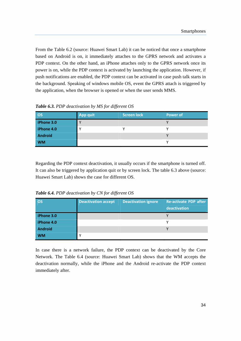
Regarding the PDP context deactivation, it usually occurs if the smartphone is turned off.
It can also be triggered by application quit or by screen lock. The table 6.3 above (source:
Huawei Smart Lab) shows the case for different OS.
Table 6.4. PDP deactivation by CN for different OS
OS Deactivation accept Deactivation ignore Re‐activate PDP after
deactivation
iPhone 3.0 Y
iPhone 4.0 Y
Android Y
WM Y
In case there is a network failure, the PDP context can be deactivated by the Core
Network. The Table 6.4 (source: Huawei Smart Lab) shows that the WM accepts the
deactivation normally, while the iPhone and the Android re-activate the PDP context
immediately after.

Smartphones
35
6.1.3 Fast Dormancy
In order to extend the life of the battery of the smartphones, the feature that was proposed
was Fast Dormancy. This way, the UE forces the network to break the data connection
once the user has downloaded what he wanted, and than the UE goes back to Idle state.
Since the UE is not spending longer periods in Active state, the battery life is improved.
Conversely, the network doesn’t have so much benefit from this. Being in Active state for
short periods means that of the user wants to connect again for sending data it has to start
a whole new connection from the Idle state. This significantly increases the signaling
traffic which wastes the network resources and could be that less number of smartphones
will be able to connect.
Using the basic form of fast dormancy i.e. switching constantly form Idle to Active and
than back to Idle again, the Android devices cause higher signaling traffic than other
devices. On the other hand, starting from iOS4.1 iPhone started to use a modified version
of Fast Dormancy which keeps the phone connected as long as the backlight is on
supposing that if it is on, the user is looking at the phone and could send a data request
any time.
To solve the problem of the huge signaling loads that was introduced by the smartphones,
the RNC vendors started using a paging channel or Cell_PCH state in the networks in
order to avoid frequent connection setups i.e. they prefer to change the UE state into PCH
rather than Idle. When the UE is about to return in Idle state after having made a data
connection, 30 signaling messages are required. While if the handset is kept in PCH
mode between active connections, which keeps the Iu connection and the RAB
unreleased, it requires only 12 signaling messages for the round trip. This way the
connection times are becoming shorter, for establishing a new connections only half a
second is needed. The UE is no longer held in Active state for long period which also
saves the battery life. [20]

Smartphones
36
Figure 6.8. Difference between disabled and enabled Cell_PCH
Although this sounds like a perfect solution for latency, battery life and signaling, there is
one problem – Fast Dormancy. The handsets that have this feature enabled are forced to
go back to Idle between data connections. Nokia Siemens Networks have proved that
having the Cell_PCH enabled in the radio equipment and a disabled Fast Dormancy
feature in the handsets, the signaling can be reduced from 30-50% and also the capacity
needed in the SGSN can be cut in half.
Some analysis were done by the Signal Processing Group, LLC about the RRC state
transition changes and the battery consumption, parallel in two networks, one of them
with Cell_PCH enabled and the other without. From the results stated in table 6.5 it can
be observed that enabling the Cell_PCH the signaling traffic has been reduced
significantly. [18]
For IM messaging, the Cell_PCH enabled network used Cell_FACH to send and receive
messages. Since the transition changes between Cell_PCH and Cell_FACH require less
signaling messages as stated before, there was a significant reduction of the signaling
load. This way also the capacity for other voice and data users was freed.
Smartphones
37
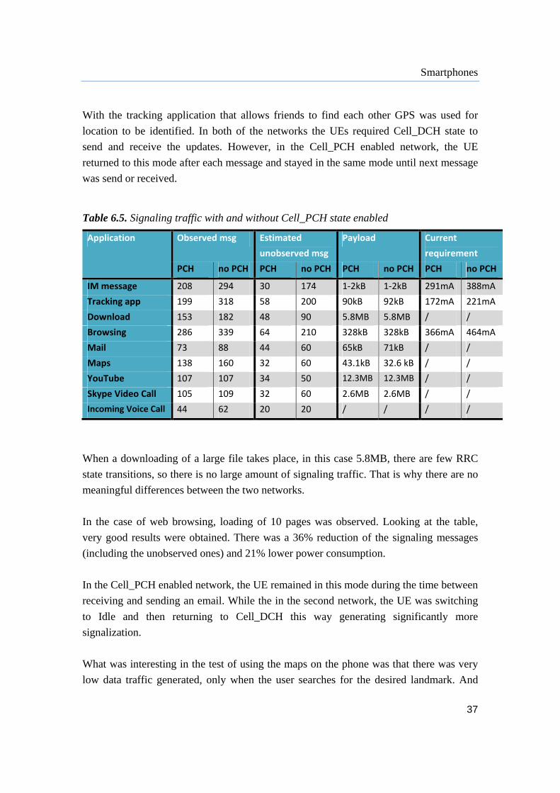
With the tracking application that allows friends to find each other GPS was used for
location to be identified. In both of the networks the UEs required Cell_DCH state to
send and receive the updates. However, in the Cell_PCH enabled network, the UE
returned to this mode after each message and stayed in the same mode until next message
was send or received.
Table 6.5. Signaling traffic with and without Cell_PCH state enabled
Application Observed msg Estimated
unobserved msg
Payload Current
requirement
PCH no PCH PCH no PCH PCH no PCH PCH no PCH
IM message 208 294 30 174 1‐2kB 1‐2kB 291mA 388mA
Tracking app 199 318 58 200 90kB 92kB 172mA 221mA
Download 153 182 48 90 5.8MB 5.8MB / /
Browsing 286 339 64 210 328kB 328kB 366mA 464mA
Mail 73 88 44 60 65kB 71kB / /
Maps 138 160 32 60 43.1kB 32.6 kB / /
YouTube 107 107 34 50 12.3MB 12.3MB / /
Skype Video Call 105 109 32 60 2.6MB 2.6MB / /
Incoming Voice Call 44 62 20 20 / / / /
When a downloading of a large file takes place, in this case 5.8MB, there are few RRC
state transitions, so there is no large amount of signaling traffic. That is why there are no
meaningful differences between the two networks.
In the case of web browsing, loading of 10 pages was observed. Looking at the table,
very good results were obtained. There was a 36% reduction of the signaling messages
(including the unobserved ones) and 21% lower power consumption.
In the Cell_PCH enabled network, the UE remained in this mode during the time between
receiving and sending an email. While the in the second network, the UE was switching
to Idle and then returning to Cell_DCH this way generating significantly more
signalization.
What was interesting in the test of using the maps on the phone was that there was very
low data traffic generated, only when the user searches for the desired landmark. And

Smartphones
38
also there was small amount of signaling traffic. The UE remained in Cell_PCH the
entire test, in the first network, and returned to Cell_DCH only at the end.
Speaking of watching videos on YouTube, one would assume that the UE would enter
Cell_DCH when the video is selected and stay there until the video is downloaded. And
this is correct. That is why small signaling traffic was generated and the results are rather
equivalent for a meaningful amount of data.
For Skype video call as well, there is relatively big amount of data and thus the results are
pretty equivalent.
The test of the incoming voice call was added, although it has nothing to do with data,
from a simple reason to see how an UE behaves when it receives a voice call. The results
should be the same in theory, the behavior was the same for both networks, transition
from Cell_FACH to Cell_DCH and then back to Idle. The number of signaling messages
could have been measured higher for the Cell_PCH disabled network because the ringing
time was longer.
3GPP came up with an idea of Network Controlled Fast Dormancy, also known as
Release 8 Fast Dormancy. With this feature the smartphones are more flexible meaning
that they can exploit the Cell_PCH on the networks that has it enabled or they can adjust
to Fast Dormancy on the vendors that don’t have the Cell_PCH supported. What happens
is that on the part where Cell_PCH is used both battery life and signaling traffic are
optimized, while on the other part that has no Cell_PCH at least the battery life is
improved by using the Fast Dormancy, but causing lots of signaling.
39
7 Radio Network Controller
The Radio Network Controller (RNC) is a key element within UTRAN which controls all
the radio resources of UTRAN. However, each RNC controls only resources under its
control. There are multiple RNCs in UTRAN and as such, control of radio resources is
done with a distributed architecture. As mentioned before, the RNC can have three
logical roles:
Controlling RNC (CRNC) – responsible for the Node Bs and all cells belonging to
it. When a UE wants to access the system, it sends a message for access to a Node
B which forwards this message onto its CRNC.
Serving RNC (SRNC) – terminates the mobile link layer communications and it is
responsible for admission control which assures that radio resources are allocated
to the user up to the availability to the network.
Drift RNC (DRNC) – the place where the mobiles physical layer communications
terminates. If there is no soft handover activity is in progress, a Drift RNC may
also be the Serving RNC.
Speaking of the functionality, we are thinking of the Radio Resource Management
(RRM) which was discussed in chapter 5. Namely, the RNC manages the allocation of
the channels so that the transport of the real traffic and the signaling can take place
simultaneously. The functions of the RNC can be divided into two groups, network based
and connection based.
The network based functions are further divided into:
Event based – functions that are preformed when required. This group consists of
the admission control and the packet scheduling. With the admission control the
stability is maintained and it is used for the required capacity of the RAN to be
achieved. While the packet scheduling manages the scheduling of the radio
resources for the NRT radio bearers.

Radio Network Controller
40
Continuous – functions that are performed constantly. This kind of a function is
the load control which should ensure that there will be no overload in the system.
If at some point the system is overloaded, it has to return the system in the normal
state as defined in as short time as possible.
On the other hand, the connection based functions take place whenever a radio link is
assigned to a connection. Here falls the power control and the handover control. With the
power control should be ensured that the power requirements are kept for the
transmission. It also takes care of maintaining the SIR targets by keeping the lowest
interference possible and providing good connection quality. The handover control
provides support for the soft handovers. It can be both RNC controlled and UE initiated.
Figure 7.1. RNC functions
As stated previously, the RNC communicates with the network elements in both the RAN
and the CN through various interfaces.
‐ Iub Interface – connection between the Node B and the RNC.
‐ Iur Interface – connects two RNCs and it manages the soft handovers. It is an
open interface.
‐ Iu-CS Interface – connects the RNC with the Core Network. Usually terminates
in the MSC via the Media Gateway. It supports circuit switched traffic.
AC
PS
LC
HCPC
AC ‐ Admission Control PS ‐ Packet Scheduler LC ‐ Load Control PC ‐ Power Control HC ‐ Handover Control

Radio Network Controller
41
‐ Iu-PS Interface – connects the RNC with the Core Network. Usually terminates in
the SGSN. It supports packet switched traffic.
‐ Iu-BC Interface - connects the RNC with the Core Network, more specifically
with the Cell Broadcast Center (CBC).
‐ Iu-PC Interface – interface between the RNC and the Stand Alone SMLC
(Serving Mobile Location Center). It provides GPS information to the RNC about
the UE positioning.
‐ Network Management Interface – connects the RNC to the Operation Support
System. It uses TCP/IP.
Figure 7.2. RNC interfaces
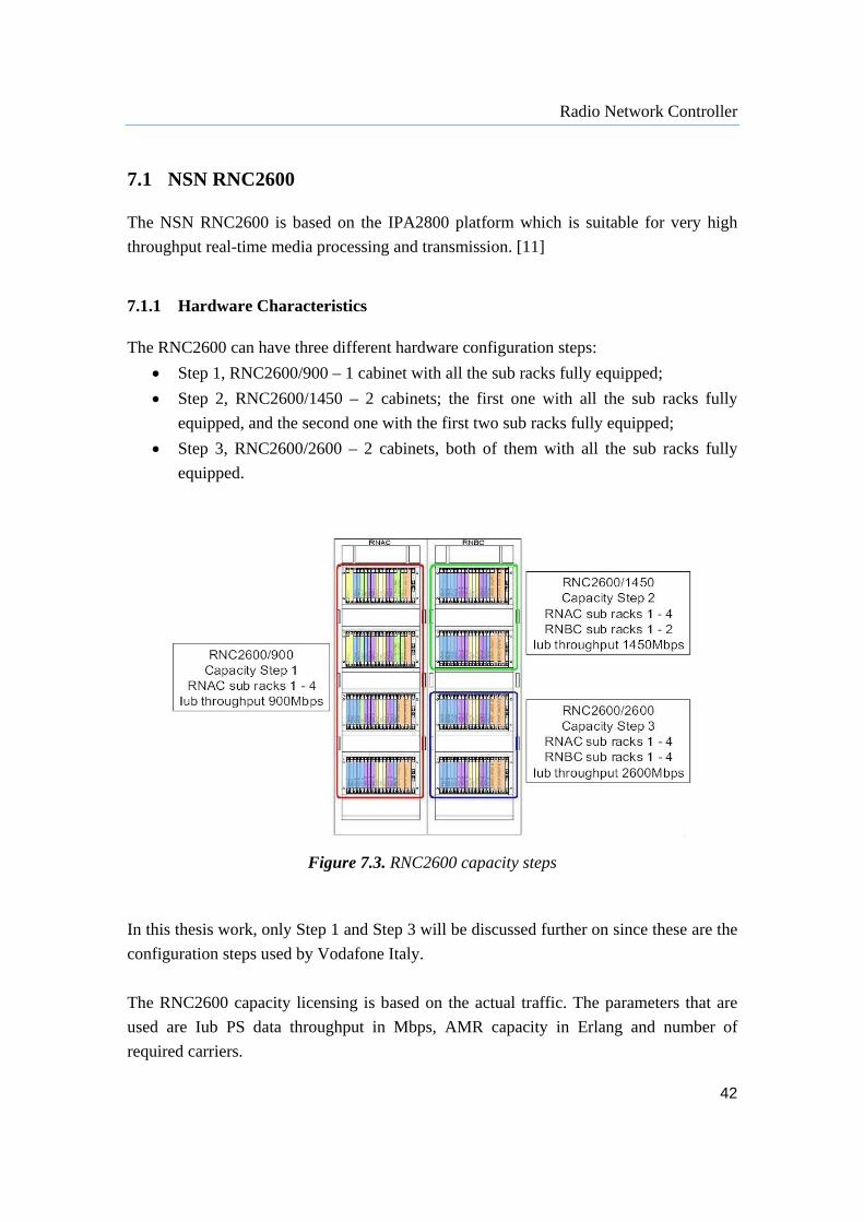
Radio Network Controller
42
7.1 NSN RNC2600 The NSN RNC2600 is based on the IPA2800 platform which is suitable for very high
throughput real-time media processing and transmission. [11]
7.1.1 Hardware Characteristics The RNC2600 can have three different hardware configuration steps:
Step 1, RNC2600/900 – 1 cabinet with all the sub racks fully equipped;
Step 2, RNC2600/1450 – 2 cabinets; the first one with all the sub racks fully
equipped, and the second one with the first two sub racks fully equipped;
Step 3, RNC2600/2600 – 2 cabinets, both of them with all the sub racks fully
equipped.
Figure 7.3. RNC2600 capacity steps
In this thesis work, only Step 1 and Step 3 will be discussed further on since these are the
configuration steps used by Vodafone Italy.
The RNC2600 capacity licensing is based on the actual traffic. The parameters that are
used are Iub PS data throughput in Mbps, AMR capacity in Erlang and number of
required carriers.

Radio Network Controller
43
Each type of RNC has different values in terms of supported services. This includes
number of subscribers, number of supported call attempts (CS and PS), Erlangs, MB,
number of carriers, number of Node Bs connected and RRC subscribers. These values
can obviously vary since many factors affect the behavior of a RNC. For instance, the
maximum number of subscribers that can be handled by a RNC2600 is affected by the
subscribers that are performing a soft handover procedure. By optimizing the handover
control parameters and the power control parameters this effect could be minimized.
Furthermore, the number of Node Bs that a RNC can control is dependent on the Iub
configuration.
A RNC cabinet is consisted of four subracks that contain a number of plug-in units which
represent a piece of hardware used for a certain function by adding the appropriate
software. Thus, these plug-in units are called functional unites and are divided in the
following groups:
‐ Computing units and their storage units;
‐ Signal processing units;
‐ Switching and multiplexing units;
‐ Network interface units;
‐ O&M server and its storage units.
The units that are most important for this thesis work are ICSU, DMPG and NPGEP and
will be the ones described below.
The Interface Control and Signaling Unit (ICSU) has the task to perform the RNC
functions connected to the signaling to the other network elements. Namely, it takes care
of the control plane. It also handles functions RRM functions. Form the signaling point of
view it takes care of:
‐ NBAP signaling (over Iub);
‐ RNSAP signaling (over Iur);
‐ RANAP signaling (over Iu);
‐ RRC signaling (between UE and RNC);
‐ ALCAP signaling (for AAL2 connections).
Radio Network Controller
44
As for the radio resource management, it is involved in:
‐ Admission control;
‐ Handover control;
‐ Load control;
‐ Packet scheduling;
‐ Management of radio resources;
‐ Management of transport resources.
ICSU has N+1 redundancy, meaning that there is one more spare board.
The Data and Macro Diversity Processor Group (DMPG) is an integral part of the Data
and Macro Diversity Combining Unit (DMCU) which is a signal processing unit in
charge of the user plane. The main functionalities are:
‐ Macrodiversity combining – the DMCU combines the signals from different base
stations choosing the best quality transport blocks into a new signal;
‐ Outer loop power control – the quality of the uplink signal is monitored and if it is
not good enough a command is send to the base station to increase the SIR value;
‐ Frame protocol processing;
‐ MAC protocol processing;
‐ Ciphering (encryption) – in UMTS the ciphering is between the UE and the
SRNC;
‐ RLC protocol processing;
‐ PDCP protocol processing;
‐ HSPA-related processing.
DMPG has SN+ redundancy which means that there is no spare unit.
The Network Processor Gigabit Ethernet Protected (NPGEP) unit is a network interface
unit which offers IP over two Gigabit Ethernet interfaces. It also performs header
translation, O&M, traffic management, performance monitoring and performance data
collection. The NPGEP is the board that decides whether to send the traffic to the ICSU
or to the DMPG. It has 2N redundancy meaning hot standby, establishing a fault-tolerant
default gateway.

Radio Network Controller
45
7.1.2 Software Characteristics The NSN RNCs have two different software releases, Ru20 and Ru30. Most of the
features are related to the capacity. [1][25]
Table 7.1. Ru20 and Ru30 Features
Ru20 Ru30
o HSDPA 64QAM
o MIMO 28Mbps
o Dual Cell HSDPA 42Mbps
o Flexible RLC in DL
o CS Voice over HSPA
o Fractional DPCH
o CPC
o HSUPA 2ms
o HSUPA 5,8Mbps
o HSPA 72 Users per Cell
o 24kbps Paging Channel
o Fast L1 Synchronization
o Direct Resource Allocation for HSPA
o Power Saving Mode for BTS
o LTE Interworking
o HSUPA DL PCH Power Control
o HSUPA Interference Cancellation Receiver
o HSUPA 16QAM
o HSUPA Inter‐Frequency Handover
o Frequency Domain Equalization
o Dual Cell HSUPA 23Mbps
o Dual Cell HSDPA with MIMO 84Mbps
o UE DRX in Cell_FACH
o Flexible RLC in UL
o MIMO 42Mbps
o High Speed Cell_FACH
o HSPA 128 Users per Cell
o Fast Dormancy
o Multi‐Band Load Balancing
o LTE PS Handover and SRVCC
o Dual Band HSDPA 42 Mbps
7.2 Huawei BSC6900 The BSC6900 is an important network element of Huawei Single RAN solution. It
supports the leading multiple radio access technologies (RATs), IP transmission mode
and has a modular design. The BSC6900 can be flexibly configured as required in
different networks. The BSC6900 satisfies the mobile network requirements for very high
capacity, high integration, high performance and low power consumption. With the same
hardware it is possible to set up a Base Station Controller (BSC), thus the name. [13]
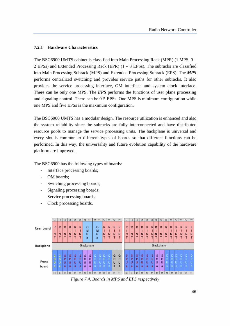
Radio Network Controller
46
7.2.1 Hardware Characteristics
The BSC6900 UMTS cabinet is classified into Main Processing Rack (MPR) (1 MPS, 0 –
2 EPSs) and Extended Processing Rack (EPR) (1 – 3 EPSs). The subracks are classified
into Main Processing Subrack (MPS) and Extended Processing Subrack (EPS). The MPS
performs centralized switching and provides service paths for other subracks. It also
provides the service processing interface, OM interface, and system clock interface.
There can be only one MPS. The EPS performs the functions of user plane processing
and signaling control. There can be 0-5 EPSs. One MPS is minimum configuration while
one MPS and five EPSs is the maximum configuration.
The BSC6900 UMTS has a modular design. The resource utilization is enhanced and also
the system reliability since the subracks are fully interconnected and have distributed
resource pools to manage the service processing units. The backplane is universal and
every slot is common to different types of boards so that different functions can be
performed. In this way, the universality and future evolution capability of the hardware
platform are improved.
The BSC6900 has the following types of boards:
‐ Interface processing boards;
‐ OM boards;
‐ Switching processing boards;
‐ Signaling processing boards;
‐ Service processing boards;
‐ Clock processing boards.
Figure 7.4. Boards in MPS and EPS respectively
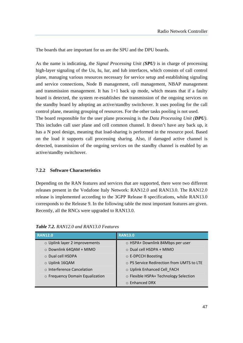
Radio Network Controller
47
The boards that are important for us are the SPU and the DPU boards.
As the name is indicating, the Signal Processing Unit (SPU) is in charge of processing
high-layer signaling of the Uu, Iu, Iur, and Iub interfaces, which consists of call control
plane, managing various resources necessary for service setup and establishing signaling
and service connections, Node B management, cell management, NBAP management
and transmission management. It has 1+1 back up mode, which means that if a faulty
board is detected, the system re-establishes the transmission of the ongoing services on
the standby board by adopting an active/standby switchover. It uses pooling for the call
control plane, meaning grouping of resources. For the other tasks pooling is not used.
The board responsible for the user plane processing is the Data Processing Unit (DPU).
This includes call user plane and cell common channel. It doesn’t have any back up, it
has a N pool design, meaning that load-sharing is performed in the resource pool. Based
on the load it supports call processing sharing. Also, if damaged active channel is
detected, transmission of the ongoing services on the standby channel is enabled by an
active/standby switchover.
7.2.2 Software Characteristics
Depending on the RAN features and services that are supported, there were two different
releases present in the Vodafone Italy Network: RAN12.0 and RAN13.0. The RAN12.0
release is implemented according to the 3GPP Release 8 specifications, while RAN13.0
corresponds to the Release 9. In the following table the most important features are given.
Recently, all the RNCs were upgraded to RAN13.0.
Table 7.2. RAN12.0 and RAN13.0 Features
RAN12.0 RAN13.0
o Uplink layer 2 improvements
o Downlink 64QAM + MIMO
o Dual cell HSDPA
o Uplink 16QAM
o Interference Cancelation
o Frequency Domain Equalization
o HSPA+ Downlink 84Mbps per user
o Dual cell HSDPA + MIMO
o E‐DPCCH Boosting
o PS Service Redirection from UMTS to LTE
o Uplink Enhanced Cell_FACH
o Flexible HSPA+ Technology Selection
o Enhanced DRX
48
8 Estimation of the Unit Loads
After understanding how a smartphone behaves in the network, in order to provide good
end-to-end service for the smartphone users, the networks have to act smart also. As it
was mentioned, the RNC is the most important node in the UTRAN, since it must process
both the data traffic and the signaling traffic. If in some case the RNC reaches overload
situation because of the signalization, there would be difficulties in managing of the data
traffic and could happen that the resources are not properly assigned. This means that the
throughput gets lower, the response time longer and the quality of the voice is worse.
Thus, the RNC should be the main objective for investigation in order to increase the
performance of the network.
Having the RNC dimensioned to manage certain amount of Erlangs and Mbps and to
support certain number of signaling procedures, with the rising number of smartphones
and the traffic that they generate, there is a need to monitor the behavior of the units that
manage both user and control plane. The goal is to maximize the broadband experience
and to ensure efficient and congestion-free connection. For this reason, to help the
accurate planning of the network for future delivery of excellent experience to the users,
models for estimating the load of the main RNC boards for user and control plane.
8.1 Key Performance Indicators Understanding the units’ behavior means doing performance measurements, this is
actually nothing more than data monitoring. Performance measurement is an effective
way of scanning the whole network at any time and effectively finding errors, bottlenecks
and suspicious behavior. [19]
There are many parameters and events that can be measured and it can happen that many
of these measurements are correlated. There is not an unique way to choose the right
parameters to be measured. Every vendor and operator has its own targets of
measurement and its own way of describing the network behavior. The general idea is to

Estimation of the Unit Loads
49
have counters placed in different nodes of the network to track node’s behavior and to
pick up performance-related data. The collected data from all the nodes is managed by
the OSS (Operations Support System).
The UTRAN with the air interfaces is the most critical part of a mobile network. Thus,
the RNCs are the perfect nodes for counters to measure the performance of the radio
interface, what was needed for the purpose of this thesis work. The measurements for the
RNCs are gathered from the OSS in defined time intervals (not in real time) and are than
elaborated and checked for consistency. This is the point where the Key Performance
Indicators (KPIs) are produced. The only difference between the performance related data
and the KPIs that are used for analysis is that the KPIs are computed by a formula. They
represent a set of selected indicators for measuring the current network performance and
trends. KPIs highlight the key factors of network monitoring and warn if there are some
potential problems. Also, KPIs are also used to prioritize the corrective actions.
KPIs can be correlated to each other or related to elements in the network topology.
When considering the UTRAN performance, we can use both the Iub and Iu related
messages to evaluate the performance and the customers perception. In fact, on the RNC
we can have counters that relates to data captured on the both interfaces.
The KPIs for an UMTS network can be grouped into the following categories [16]:
Accessibility: the possibility for the user to receive the requested service from the
system. The main procedures are RRC connection and RAB setup. These items
can be calculated per cell and per RNC, and the RNC level KPI is calculated by
aggregating all the cell counters that belong to the RNC.
Retainability: the ability of the user to retain the requested service for the desired
duration once connected. These items can be calculated per cell or per RNC. The
RNC level KPIs can be calculated by aggregating all the cell counters and Iur
counters.
Availability: mainly indicates resource utilization such as Radio, bandwidth or
CPU load.
Coverage: monitoring cell Interference status and Soft Handover Gain in a RNC
or a cluster
Mobility: monitoring the successful rate for several kinds of handover features or
service mode changing in different scenarios.
Estimation of the Unit Loads
50
Integrity: mainly indicates the service capabilities for PS/HSPA throughput in the
busy hour in each cell and the service UL Average BLER for evaluating the UL
BLER value of services in each cell.
Traffic: evaluates the circulated traffic, CS Erlang, PS Traffic, Mean UE number
for several kinds of services in a RNC or cluster.
What is also important for the KPIs is to be able to estimate them. This way the network
planning is simplified in the sense that we can find out which is the part that is having an
odd behavior and pay more attention to it. Knowing where the problems are coming
from, we would investigate how to fix a particular point rather then changing the whole
network.
The strategy of the operators is to optimize the network in order to provide a good
subscriber’s experience which is the key factor of success. The users are just interested to
make a voice call or a data call and if everything works well they will have a positive
impression. If there is a problem, then:
‐ Subscribers might are not able to register to the network
‐ Subscribers might are not able to set up calls
‐ The calls made might be dropped
‐ Low throughput could be measured
‐ The quality of transmitted information could be bad, which affects conversation
calls (voice, video-telephony) especially
The users are not interested why these problems occur, they just don’t want them to
happen. The network engineers have to find the root of the problem and try to fix it.
8.2 NSN Units
8.2.1 ICSU Model
As explained previously, the ICSU board is in charge of the signaling traffic in the
network. The signaling part is the most interesting to look at when speaking about
smartphones, as it was mentioned in chapter 6, due to their peculiar behavior in the
network. So, it would be logical to take into account all the KPIs that contribute to the
signaling part of the network. These main KPIs involved are listed below. Each KPI has a

Estimation of the Unit Loads
51
weight given by the vendor, which represents the level of importance of the KPI for the
ICSU load. Hourly measurements were used for analysis.
BHCA_CS – number of CS call attempts over the Iub interface.
BHCA_PS – number of PS call attempts over the Iub interface.
Paging – includes service request messages over both Iu and Iub.
SHO (Soft HandOver) – messages exchanged over Iub when the UE is supported
from two or more cells during a call. They consist of information about the
quality of the signal.
NAS (Non Access Stratum) – a set of control protocols between the CN and UE.
These signaling messages can be found on both Iu and Iub interfaces. They are
involved in the connection set up and location update.
NBAP (Node B Application Part) – a signaling protocol used for communication
between the Node B and the RNC over Iub, it is responsible for the control of the
RNC over the Node B. These signaling messages are used for synchronization of
the radio link configuration.
DCH_to_FACH – a transition based on buffer utilization for a certain period of
time. If the buffer is full, the call is moved to DCH. This transition also takes
place due to low usage. If only very small amounts of data need to be transmitted
than FACH is used. While, if the data buffer is empty, the call is moved to FACH
through a procedure of radio bearer reconfiguration. The measures used are some
of both way transitions.
HSDSCH_to_FACH – the same as the previous type of transition just that here
the call is carried on a high speed channel before it is moved to FACH.
FACH_to_PCH – a transition based on the status of the transmission buffer. If
the buffer is empty for a certain time, a transition to PCH occurs. Moving to PCH
happens due to inactivity or after cell update.

Estimation of the Unit Loads
52
DCH_to_PCH – when the RAB is meant to be unreleased between active
connections. If the PDP context remains active, but it is detected that in active
connection for a certain time no data is transferred at all, the mobile is transferred
to PCH.
However, using all the KPIs would result in very complicated model that will be hard to
use. Moreover, it is not possible to give estimation for all of them at first place in order to
use this data in the final estimation of the load. So, the goal was to build some simpler
model which will be easy to implement, but still giving good results in estimating the
ICSU load.
From the KPIs listed above, BHCA_CS and BHCA_PS are the ones with highest weights
given by the vendor, meaning that those are the main factors that contribute to the load of
the ICSU board. Moreover, the number of the call attempts, both circuit and packet
switch can be estimated from the number of users and traffic mix profile. So, these two
KPIs were the one to be exploited for the estimation model, together with their weights
and the maximum number of supported BHCA_CS and BHCA_PS. The number of
supported CS and PS calls is roughly three times higher for the Step 3 RNCs.
The main idea for this model was to find a way to compute the ICSU load considering the
capacity used from the signaling that is being done for the call attempt messages
exchanged through the Iub interface. For doing that we considered finding the capacity as
a mix of the two types of traffic, CS and PS, and weighting them with the appropriate
vendor specific values for the maximum capacity that can be handled by the RNCs (in
terms of maximum number of CS and PS call attempts).
The measurements from the counters were taken hourly and the average values of the
actual ICSU load were used for training.
The formula that we proposed, taking into account only the values mentioned, is:
bcapmixed
callsPScallsCSaloadICSU
_
__*_ 8.1
where,

Estimation of the Unit Loads
53
callsPScallsCS
PSrefcallsPSCSrefcallsCScapmixed
__
_*__*__
8.2
The CS_calls and PS_calls represent the weighted values of the BHCA_CS and
BHCA_PS (using the weights given by the vendor), while the ref_CS and the ref_PS are
the maximum number of supported BHCA_CS and BHCA_PS (also vendor defined).
So, basically, the formula 8.1 is a weighted and shifted version of the used capacity,
given the fact that we have a ratio between the sum of the actual CS and PS calls and the
mixed capacity of the ICSU board.
Since there are two different capacity steps, a and b will be discussed accordingly.
When trying to estimate the ICSU load for the RNC of capacity Step 1, what was noticed
was that they had kind of different dependence of the used capacity. Namely, the samples
of the estimation were following the same line, but moved for some factor. We realized
that this was due to the different traffic share that the RNCs are dealing with. Actually
that is why the shifting parameter b was added.
The adjustment factor was computed as the difference between the maximum number of
the packet switch call attempts and the maximum number of the circuit switch call
attempts for a given RNC:
CSBHCAPSBHCAb _max_max 8.3
The coefficient a was found to be 5,6. So, finally, for estimation of the ICSU load for the
Step 1 NSN RNCs we use:
bcapusedSteploadICSU _*6,51__ 8.4
The same philosophy was used for the RNCs with capacity Step 3. Unlike the Step 1
RNCs, the Step 3 RNCs have two different software releases, Ru20 and Ru30. Since the
Step 1 RNCs were all Ru20, the same coefficient was used for the Step 3 Ru20 RNCs,
with the difference that in the formula for the used capacity we considered the reference

Estimation of the Unit Loads
54
values of Step 3. The parameter b was found in the same way for any RNC respectively,
applying the formula 8.3.
In the case of Ru30, different value for the parameter a had to be used. The value found
was 4. The formulas 8.5 and 8.6 respectively show the models for the Ru20 and Ru30
RNCs with capacity Step 3.
bcapusedRuSteploadICSU _*6,520_3__ 8.5
bcapusedRuSteploadICSU _*430_3__ 8.6
Having to use different coefficients in the equations for Ru20 and Ru30 and having the
models divided in a way by the software release it’s not strange. It shouldn’t be surprising
that RNCs having different releases have different behavior, since improvements and
optimizations in the software can bring benefits and changes in the signaling part that is a
part which requires higher computational effort (now even more with the smartphones on
the market) and this is the reason that the changes while estimating the load are easily
being noticed when speaking about the ICSU. This will be shown through an example
further on.
This model has proved that although all the KPIs that were elaborated have their own
contribution to the load of the ICSU board, there is no need to use all of them in order the
load to be properly estimated. Moreover, it is extremely a tough job to have all this
parameters with right estimation, to be able to use them in the final model.
It was shown that only by using the number of CS and PS calls it is possible to build a
model that will give pretty good estimation of the ICSU load. The results are given in the
table 8.1.
The respective error was computed as:
loadICSUavgICSUError __ 8.7
where ICSU_avg is the actual average ICSU load, and ICSU_load is the load that we had
estimated with the model 8.1 that was presented.
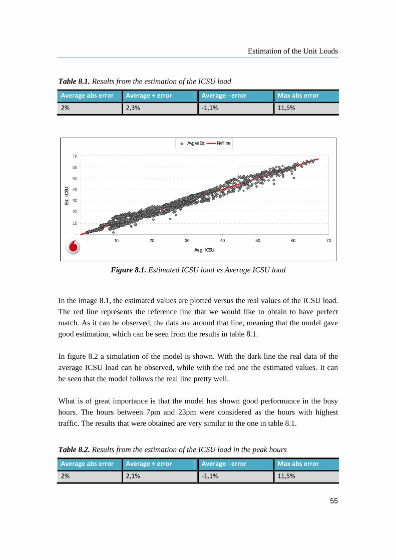
Estimation of the Unit Loads
55
Table 8.1. Results from the estimation of the ICSU load
Average abs error Average + error Average ‐ error Max abs error
2% 2,3% ‐1,1% 11,5%
Figure 8.1. Estimated ICSU load vs Average ICSU load
In the image 8.1, the estimated values are plotted versus the real values of the ICSU load.
The red line represents the reference line that we would like to obtain to have perfect
match. As it can be observed, the data are around that line, meaning that the model gave
good estimation, which can be seen from the results in table 8.1.
In figure 8.2 a simulation of the model is shown. With the dark line the real data of the
average ICSU load can be observed, while with the red one the estimated values. It can
be seen that the model follows the real line pretty well.
What is of great importance is that the model has shown good performance in the busy
hours. The hours between 7pm and 23pm were considered as the hours with highest
traffic. The results that were obtained are very similar to the one in table 8.1.
Table 8.2. Results from the estimation of the ICSU load in the peak hours
Average abs error Average + error Average ‐ error Max abs error
2% 2,1% ‐1,1% 11,5%
-
10
20
30
40
50
60
70
- 10 20 30 40 50 60 70
Avg_ICSU
Est_
ICSU
Avg vs Est Ref line

Estimation of the Unit Loads
56
Figure 8.2. ICSU model simulation
As stated before, another aspect that is worth mentioning is that during the test period,
when trying to test the model on newer data, it was noticed that some Step 1 RNCs
behaved different than before and giving bad results. We tried to use the Ru30 value for
the parameter a and according to the results, which are showen in figure 8.3, this seemed
like a reasonable idea. It turned out that these RNCs have experienced software upgrade
from Ru20 to Ru 30, and after applying the coefficients for Ru30 the results continued
being good. We have seen that the software upgrade truly influences the computation of
the ICSU load, as it was mentioned before. This way we proved that the model is very
stable and accurate and even has the power to find this kind of changes.
-
10
20
30
40
50
60
70
80
1 4 7 10 13 16 19 22 25 28 31 34 37 40 43 46 49 52 55 58 61 64 67 70 73 76 79 82 85 88 91
ICSU_load
est_ICSU
-
10
20
30
40
50
60
70
80
1 4 7 10 13 16 19 22 25 28 31 34 37 40 43 46 49 52 55 58 61 64 67 70 73 76 79 82 85 88 91

Estimation of the Unit Loads
57
Figure 8.3. Noticeable change from Ru20 to Ru30
8.2.2 DMPG Model
The DMPG board takes care of the traffic in the user plane. That means that that it
handles both the voice and the data traffic flows. What was considered to be a good
estimator for the DMPG load was the RNC filling ratio. The formula that is given below
considers only two KPIs, AMR capacity in Erlangs and IuPS Throughput in Mbps. [14]
)(_
)(_
)(
)(_
capacityIuPSThroughput
measuredIuPSThroughput
capacityErlangs
measuredErlangsFillRateRNC 8.8
This formula can also be expressed as the some of the fill rates of the CS and PS part:
PSFillRateErlFillRateFillRateRNC ___ 8.9
TORNC05 May 2012
-
10
20
30
40
50
60
70
80
1 7 13 19 25 31 37 43 49 55 61 67 73 79 85 91 97 103 109 115 121 127 133 139 145 151 157 163
Avg_ICSU
Est_ICSU
TORNC05 May 2012
-
10
20
30
40
50
60
70
80
1 7 13 19 25 31 37 43 49 55 61 67 73 79 85 91 97 103 109 115 121 127 133 139 145 151 157 163
Avg_ICSU
Est_ICSUNoticeable change from Ru20 to Ru30 ICSU estimation after parameter change
ICSU estimation
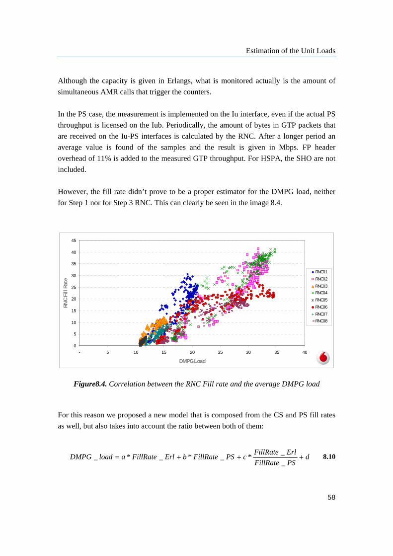
Estimation of the Unit Loads
58
Although the capacity is given in Erlangs, what is monitored actually is the amount of
simultaneous AMR calls that trigger the counters.
In the PS case, the measurement is implemented on the Iu interface, even if the actual PS
throughput is licensed on the Iub. Periodically, the amount of bytes in GTP packets that
are received on the Iu-PS interfaces is calculated by the RNC. After a longer period an
average value is found of the samples and the result is given in Mbps. FP header
overhead of 11% is added to the measured GTP throughput. For HSPA, the SHO are not
included.
However, the fill rate didn’t prove to be a proper estimator for the DMPG load, neither
for Step 1 nor for Step 3 RNC. This can clearly be seen in the image 8.4.
Figure8.4. Correlation between the RNC Fill rate and the average DMPG load
For this reason we proposed a new model that is composed from the CS and PS fill rates
as well, but also takes into account the ratio between both of them:
dPSFillRate
ErlFillRatecPSFillRatebErlFillRatealoadDMPG
_
_*_*_*_ 8.10
0
5
10
15
20
25
30
35
40
45
- 5 10 15 20 25 30 35 40
DMPG Load
RN
C F
ill R
ate
RNC01
RNC02
RNC03
RNC04
RNC05
RNC06
RNC07
RNC08

Estimation of the Unit Loads
59
where the coefficients a, b and c vary according to the capacity step of the RNC. As in
the case of the ICSU load, it was noticed that the estimations of the RNCs were shifted,
we had to investigate what is the reason. We have found out that there is different
variation of the values of the throughput in the RNCs. Therefore, the adjustment factor d
was added which is expressed as the ratio between the maximum and the minimum PS
fill rate:
PSFillRate
PSFillRated
_min
_max 8.11
Unlike the signaling part, the data part of the network is more dependent on the hardware
which is obvious because here we are dealing with the real data being transferred through
network and it’s the capacity what matters. That is why we have coefficients that differ
according to the step size.
As mentioned before, the fill rates are computed from the measured values of the Erlangs
and the throughput, and the capacity values of the RNC with respect to these two. The
coefficients that were found for the DMPG model for Step 1 RNCs are given in table 8.3.
Table 8.3. DMPG coefficients for Step 1 RNCs
Step 1 RNC2600 a b c
0,9 0,3 2,5
So, for the Step 3 RNCs, regardless if their software is Ru20 on Ru30, there are no user
plane capacity differences for both Erlangs and IuPS. Therefore, for all the RNCs the
same coefficients are used. They are given in table 8.4.
Table 8.4. DMPG coefficients for Step 3 RNCs
Step 3 RNC2600 a b c
1,15 0,35 3
After proving that the RNC fill rate computed by the formula 8.6 is not corresponding
well to the load of the DMPG unit, the model 8.8 shows that with a simple combination
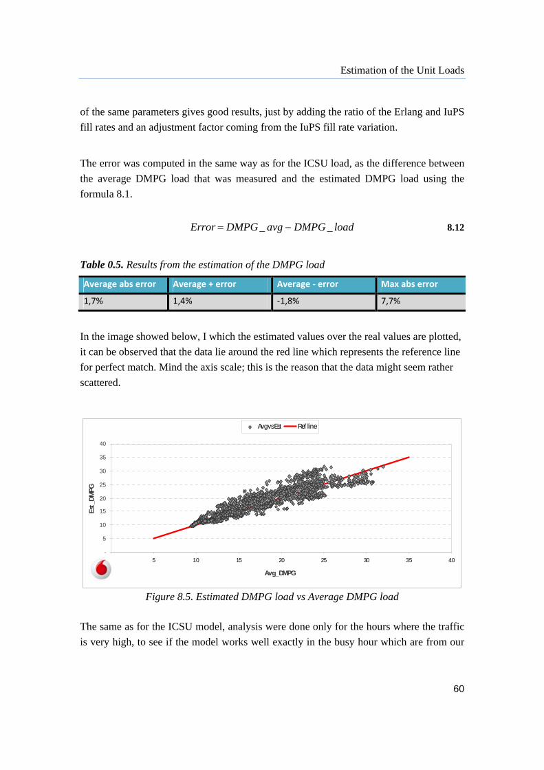
Estimation of the Unit Loads
60
of the same parameters gives good results, just by adding the ratio of the Erlang and IuPS
fill rates and an adjustment factor coming from the IuPS fill rate variation.
The error was computed in the same way as for the ICSU load, as the difference between
the average DMPG load that was measured and the estimated DMPG load using the
formula 8.1.
loadDMPGavgDMPGError __ 8.12
Table 0.5. Results from the estimation of the DMPG load
Average abs error Average + error Average ‐ error Max abs error
1,7% 1,4% ‐1,8% 7,7%
In the image showed below, I which the estimated values over the real values are plotted,
it can be observed that the data lie around the red line which represents the reference line
for perfect match. Mind the axis scale; this is the reason that the data might seem rather
scattered.
Figure 8.5. Estimated DMPG load vs Average DMPG load
The same as for the ICSU model, analysis were done only for the hours where the traffic
is very high, to see if the model works well exactly in the busy hour which are from our
-
5
10
15
20
25
30
35
40
- 5 10 15 20 25 30 35 40
Avg_DMPG
Est_
DM
PG
Avg vs Est Ref line
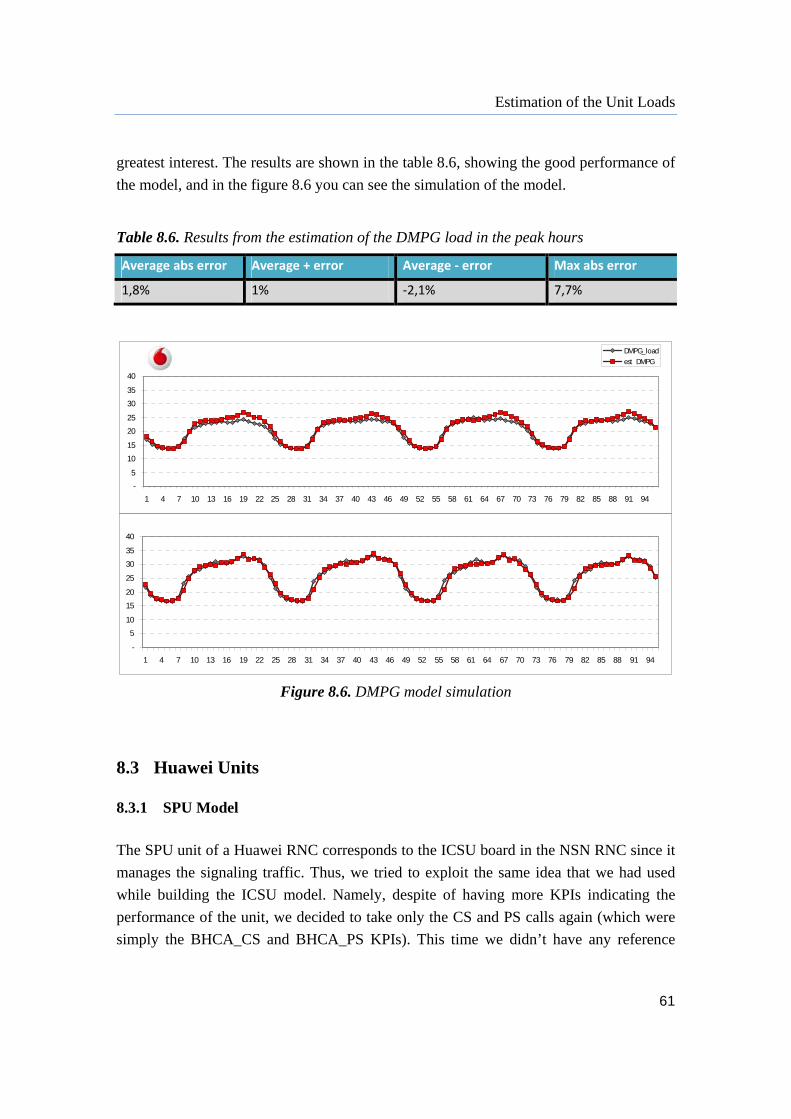
Estimation of the Unit Loads
61
greatest interest. The results are shown in the table 8.6, showing the good performance of
the model, and in the figure 8.6 you can see the simulation of the model.
Table 8.6. Results from the estimation of the DMPG load in the peak hours
Average abs error Average + error Average ‐ error Max abs error
1,8% 1% ‐2,1% 7,7%
Figure 8.6. DMPG model simulation
8.3 Huawei Units
8.3.1 SPU Model
The SPU unit of a Huawei RNC corresponds to the ICSU board in the NSN RNC since it
manages the signaling traffic. Thus, we tried to exploit the same idea that we had used
while building the ICSU model. Namely, despite of having more KPIs indicating the
performance of the unit, we decided to take only the CS and PS calls again (which were
simply the BHCA_CS and BHCA_PS KPIs). This time we didn’t have any reference
-
5
10
15
20
25
30
35
40
1 4 7 10 13 16 19 22 25 28 31 34 37 40 43 46 49 52 55 58 61 64 67 70 73 76 79 82 85 88 91 94
DMPG_load
est_DMPG
-
5
10
15
20
25
30
35
40
1 4 7 10 13 16 19 22 25 28 31 34 37 40 43 46 49 52 55 58 61 64 67 70 73 76 79 82 85 88 91 94

Estimation of the Unit Loads
62
values given by the vendor to refer to, so consequently we run into some difficulties
while building the model.
When we were studying the dependence of the SPU load form both the CS and PS calls,
it was proved that the load mainly depends on the number of PC calls, as shown in the
figure 8.7. But the first question that came to our mind was why there are two different
groups of RNCs? Why does it seem that the data are lying on lines with two different
slopes? It can be observed that apparently the RNC’s data (in terms of SPU load – PS
calls dependence) form each group lie on parallel lines. Therefore, we could suppose that
there is something that makes these RNCs defer. Unfortunately it is not like in the case of
ICSU, where we had division according to the software release, since recently all the
RNCs were upgraded to RAN13.0. We have to look for the cause of this problem
elsewhere.
Figure 8.7. SPU load depending on PS calls A simple equation for estimating the model was proposed:
bcallsPSacallsCSloadSPU _*_*02,0_ 8.13
where the coefficient a is different for the two types of RNC (shown in the table 8.7), and
b is the adjustment factor which depends on the traffic share.
SPU dependence on the number of PS calls
0
5
10
15
20
25
30
35
0 50 100 150 200 250
PS calls
SPU load
RNC1
RNC2
RNC3
RNC4
RNC5
RNC6
RNC7
RNC8
RNC9
RNC10
RNC11
RNC12
RNC13
RNC14

Estimation of the Unit Loads
63
Table 8.7. SPU coefficients
Type a
Type 1 0,25
Type 2 0,1
Maybe it didn’t seem promising in the beginning, but the model showed good results.
Table 80.8. Results from the estimation of the SPU load
Average abs error Average + error Average ‐ error Max abs error
0,86% 0,47% ‐1,01% 3,77%
Figure 8.8. Estimated SPU load vs Average SPU load
From the table with the errors and the figure showing the real load versus the estimated
one, we can conclude that the model estimates the SPU quite good. What is even more
encouraging is that by looking at the busy hours only, the errors were similar, pretty low
error in the hours with high traffic. This can be noticed in the graphs below which show
the simulation of the model.
0
5
10
15
20
25
30
35
40
0 5 10 15 20 25 30 35 40
Avg_DPU
Est_DPU
Avg vs Est Ref line
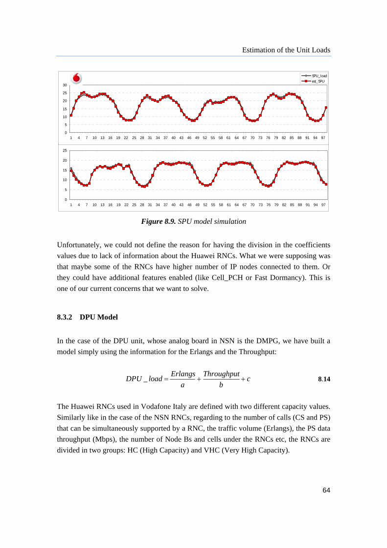
Estimation of the Unit Loads
64
Figure 8.9. SPU model simulation
Unfortunately, we could not define the reason for having the division in the coefficients
values due to lack of information about the Huawei RNCs. What we were supposing was
that maybe some of the RNCs have higher number of IP nodes connected to them. Or
they could have additional features enabled (like Cell_PCH or Fast Dormancy). This is
one of our current concerns that we want to solve.
8.3.2 DPU Model
In the case of the DPU unit, whose analog board in NSN is the DMPG, we have built a
model simply using the information for the Erlangs and the Throughput:
cb
Throughput
a
ErlangsloadDPU _ 8.14
The Huawei RNCs used in Vodafone Italy are defined with two different capacity values.
Similarly like in the case of the NSN RNCs, regarding to the number of calls (CS and PS)
that can be simultaneously supported by a RNC, the traffic volume (Erlangs), the PS data
throughput (Mbps), the number of Node Bs and cells under the RNCs etc, the RNCs are
divided in two groups: HC (High Capacity) and VHC (Very High Capacity).
0
5
10
15
20
25
1 4 7 10 13 16 19 22 25 28 31 34 37 40 43 46 49 52 55 58 61 64 67 70 73 76 79 82 85 88 91 94 97
0
5
10
15
20
25
30
1 4 7 10 13 16 19 22 25 28 31 34 37 40 43 46 49 52 55 58 61 64 67 70 73 76 79 82 85 88 91 94 97
SPU_load
est_SPU
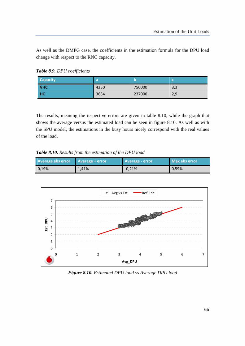
Estimation of the Unit Loads
65
As well as the DMPG case, the coefficients in the estimation formula for the DPU load
change with respect to the RNC capacity.
Table 8.9. DPU coefficients
Capacity a b c
VHC 4250 750000 3,3
HC 3634 237000 2,9
The results, meaning the respective errors are given in table 8.10, while the graph that
shows the average versus the estimated load can be seen in figure 8.10. As well as with
the SPU model, the estimations in the busy hours nicely correspond with the real values
of the load.
Table 8.10. Results from the estimation of the DPU load
Average abs error Average + error Average ‐ error Max abs error
0,19% 1,41% ‐0,21% 0,59%
Figure 8.10. Estimated DPU load vs Average DPU load
0
1
2
3
4
5
6
7
0 1 2 3 4 5 6 7
Avg_DPU
Est_DPU
Avg vs Est Ref line
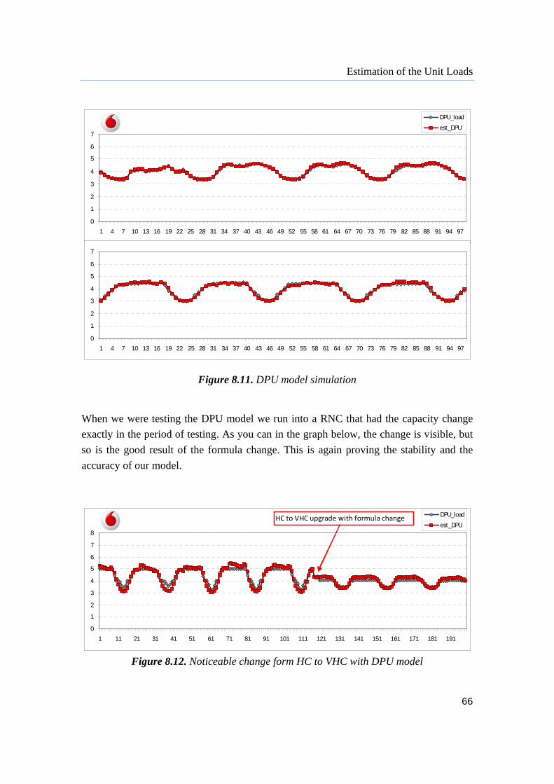
Estimation of the Unit Loads
66
Figure 8.11. DPU model simulation
When we were testing the DPU model we run into a RNC that had the capacity change
exactly in the period of testing. As you can in the graph below, the change is visible, but
so is the good result of the formula change. This is again proving the stability and the
accuracy of our model.
Figure 8.12. Noticeable change form HC to VHC with DPU model
0
1
2
3
4
5
6
7
1 4 7 10 13 16 19 22 25 28 31 34 37 40 43 46 49 52 55 58 61 64 67 70 73 76 79 82 85 88 91 94 97
DPU_load
est_DPU
0
1
2
3
4
5
6
7
1 4 7 10 13 16 19 22 25 28 31 34 37 40 43 46 49 52 55 58 61 64 67 70 73 76 79 82 85 88 91 94 97
0
1
2
3
4
5
6
7
8
1 11 21 31 41 51 61 71 81 91 101 111 121 131 141 151 161 171 181 191
DPU_load
est_DPUHC to VHC upgrade with formula change

Estimation of the Unit Loads
67
8.4 Review As described previously, for the both the NSN RNCs and the Huawei ones, we tried to
build some simpler models by using few KPIs and still getting the desired results which
would give good estimation of the unit loads for the future and this way help the network
to be optimized in order congestion to be avoided.
Starting from NSN, which are the RNCs with higher load and therefore more complicated
to estimate, we have started with an idea to compute the load caused by the signaling
traffic only using the number of CS and PS calls. While for estimating the data traffic
load, simply using the Erlangs and the Throughput. As we have proved that these are the
main factors that influence the units load and their values are enough to have a future
estimation, we have tried to do the same with the Huawei RNCs. Although their boards
were less loaded, we run into difficulties since we didn’t have any vendor specific values
(like the weights and the capacities in the NSN case) which could have helped us to build
the models in easier and more accurate way.
Moreover, in the period of building and testing the models, both the NSN and Huawei
RNCs have been constantly undergoing various changes such as software upgrade,
capacity extensions, parameter configuration, nodes rehoming, changing the typology of
the nodes connected etc. Due to these modifications, the coefficients were changing as
well, especially the adjustment factors. That is why we have to constantly check if some
improvements were made so that we can react on time. What is most important is that the
basics of the formulas don’t change. As soon as the parameterization changes are over
and guaranteed for a longer period, we would have stable coefficients.

68
9 Future Work
Despite of keeping track of the coefficients in the models that were discussed, we are
focusing also on NPGEP. As described in chapter 7, the NPGEP unit in a NSN RNC is
the board that looks at the traffic and regarding the fact whether there is data or signaling,
it the sends it either to the DMPG or to the ICSU unit accordingly.
So, the NPGEP unit is pretty interesting board to investigate as well since it deals with
both the data and signaling traffic, but that’s why it’s the most complicated one. It’s not
only the KPIs that we used for the other two boards where we need to put our attention
to, but also the type of the connectivity to the RNCs is what plays a big role. It is
important to check whether the nodes are IP or ATM, since the ATM connection doesn’t
involve NPGEP at all, while higher number of IP nodes imposes higher NPGEP load.
Therefore, building an estimation model for the NPGEP unit is our next goal on which
we are currently working on.
69
10 Conclusion
The smartphones revolution is enjoyed by the users, but it gives headaches to the vendors
and operators whose network systems were not optimized for these devices from the
beginning. The frequent data activities, mostly with low volumes of data transfer, have
brought significant increase of the signaling traffic and also have led to high battery
drain.
On the one hand, the users are happy with the variety of applications they are able to use,
but on the other hand they are complaining for the battery life, and the lasting and the
quality of the connection. Moreover, the applications are used irregularly and a new
launching of an application can crash the network.
A smartphone generates lot more signaling per transferred MB than a laptop user.
Namely, the number of messages for managing mobility and resources exchanged
between the UE and the network is much higher than the ones provided by the laptops.
And as the number of smartphone users is continuously growing, this effect can be large.
Speaking for the battery life, all the different applications that are mostly simultaneously
used load the device and spend the battery. Using the smartphone actively the display
consumes large amounts of power. While when the user is inactive, 3G radio is a big
power consumer.
These problems have imposed certain challenges to the operators, vendors (of both
infrastructure and devices) and developers. Operators and network equipment vendors
need to dimension and optimize the network to lower the signaling e.g. enabling
Cell_PCH state as it was mentioned. The smartphone vendors have to cooperate with the
networks, managing the fast dormancy. And the developers should optimize the
background traffic by small and not so frequent keep-alive messages and transmit them
all at ones.
70
Finally, the challenge for managing the smartphones impact on the network is actually a
trade-off between the efficiency of the smartphone battery, efficient use of the radio
resources, managing the signaling and the network resources and lowering the latency.
[21]
By providing these models for estimating the RNC load, we tried to help the network
dimensioning in order to prevent overloads which would cause reduced performance of
the network in the future and affect the user experience, hoping to keep the services on
the highest possible level.
71
References
[1] “3G RAN Capacity Optimization: Working InstructionsRU10/RU20”, Nokia
Siemens Networks, 2010
[2] Sudhir Kumar Baghel, Kirti Keshav & Venkateswara Rao Manepalli, ”An
Investigation Into Traffic Analysis for Diverse Data Applications on Smartphones”,
IEEE National Conference on Communications (NCC), 2012
[3] Min Woo Kim, Dong Geun Yun, Jong Min Lee, and Seong Gon Choi, “Battery Life
Time Extension Method Using Selective Data Reception on Smartphone”, IEEE
International Conference on Advanced Communication Technology (ICACT), 2012
[4] “Behavior Analysis of Smartphone”, Huawei Technologies, 2010
[5] Harri Holma and Antti Toskala, “HSDPA/HSUPA for UMTS: High Speed Radio
Access for Mobile Communications”, Nokia Networks Finland, 2006
[6] Di Pablo Tapia, Jun Liu, Yasmin Karimli, Martin Feuerstein, “HSPA Performance
and Evolution: A Practical Perspective”, 2009
[7] “HSPA+ for Enhanced Mobile Broadband”, Qualcomm Incorporated, 2009
[8] “HSPA+ Procedures”, K Labs S.r.l.
[9] Meik Kottkamp, “HSPA+ Technology Introduction, Application Note”, Rohde &
Schwarz, 2009
[10] “Long Term HSPA Evolution”, Nokia Siemens Networks, 2010
[11] “NSN RNC2600”, Nokia Siemens Networks, 2008
[12] “RAN12.0 Basic Feature Description”, Huawei Technologies, 2010
[13] “RAN12.0 BSC6900 Product Description”, Huawei Technologies, 2009
[14] John Griffiths, “RNC Performance Monitoring Guidelines”, Vodafone Italy, 2010
[15] Pekka Varis, “Role and Evolution of Radio Network Controllers”, Nokia, 2006
[16] “Single RAN KPI Reference”, Huawei Technologies, 2009
[17] “Smart Networks for Smart Devices”, Nokia Siemens Networks, 2010
[18] “Smartphones and a 3G Network”, Signals Research Group, 2010
[19] Ralf Kreher, “UMTS Performance Measurement: A Practical Guide to KPIs for the
UTRAN Environment”, Tektronix MPT Berlin GmbH & Co. KG, 2006

72
[20] “Understanding Smartphone Behavior in the Network”, Nokia Siemens Networks,
2010
[21] Per Willars, “Understanding Smartphone Traffic Impact on Battery and Networks”,
Ericsson, 2010
[22] Ki-Ho Lee, Jong-Ho Park, and Jong-Seog Koh, “User Experience Analysis of
Smartphone Web Surfing in UMTS Networks”, IEEE Vehicular Technology
Conference Fall, 2010
[23] Harri Holma and Antti Toskala , “WCDMA for UMTS – HSPA Evolution and LTE”,
Nokia Networks Finland, 2007
[24] “WCDMA RAN Key Performance Indicators”, Nokia Siemens Networks, 2007
[25] “WCDMA RAN, Rel. Ru30, Feature Descriptions”, Nokia Siemens Networks, 2010