Federica Bondioli Professore Associato di Scienza e Tecnologia dei ...
1398SFD0013A00 - 11-03-16
398SFD0013A00
LÜFTER-STEUERUNGSSYSTEM FAN DRIVEFAN DRIVE SYSTEMSSISTEMI FAN DRIVE
2 398SFD0013A00 - 11-03-16
3
4
8
10
12
18
19
20
22
INHALTSVERZEICHNIS
EINLEITUNG
BESCHREIBUNG
ELEKTRONISCHE BAUELEMENTE
ALLGEMEINE GEBRAUCHSANWEISUNGEN
VERSION
BESTELLSCHLÜSSEL (MOTOR)
BESTELLSCHLÜSSEL FÜR MIKROCONTROLLER (ELEKTRONIKKARTE)
ELEKTRONISCHES ZUBEHÖR – SENSOREN
ELEKTRONISCHES ZUBEHÖR – PROGRAMMIER-KABEL
INDEX
INTRODUCTION
DESCRIPTION
ELECTRONIC COMPONENTS
OPERATING INSTRUCTIONS
VERSIONS
ORDERING INSTRUCTIONS (MOTOR)
ORDERING INSTRUCTIONS (ELECTRONIC BOARDS)
ELECTRONIC ACCESSORIES – SENSORS
ELECTRONIC ACCESSORIES –STANDARD WIRING
INDICE
INTRODUZIONE
DESCRIZIONE
COMPONENTI ELETTRONICI
ISTRUZIONI GENERALI DI IMPIEGO
VERSIONI
ISTRUZIONI PER L’ORDINAZIONE (MOTORE)
ISTRUZIONI PER L’ORDINAZIONE (SCHEDE ELETTRONICHE)
ACCESSORI ELETTRONICI – SENSORI
ACCESSORI ELETTRONICI – CABLAGGI STANDARD
3398SFD0013A00 - 11-03-16
EINLEITUNG
Lüfter-Steuerungssystem
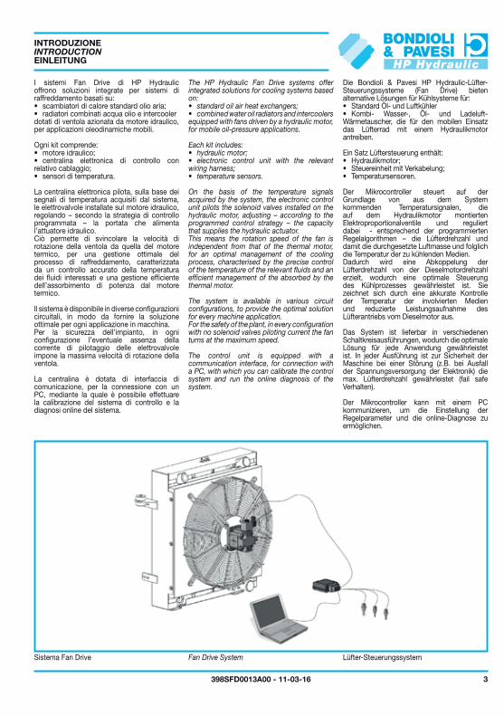
Die Bondioli & Pavesi HP Hydraulic-Lüfter-Steuerungssysteme (Fan Drive) bieten alternative Lösungen für Kühlsysteme für:• Standard Öl- und Luftkühler• Kombi- Wasser-, Öl- und Ladeluft-Wärmetauscher, die für den mobilen Einsatz das Lüfterrad mit einem Hydraulikmotor antreiben.
Ein Satz Lüftersteuerung enthält:• Hydraulikmotor;• Steuereinheit mit Verkabelung;• Temperatursensoren.
Der Mikrocontroller steuert auf der Grundlage von aus dem System kommenden Temperatursignalen, die auf dem Hydraulikmotor montierten Elektroproportionalventile und reguliert dabei - entsprechend der programmierten Regelalgorithmen – die Lüfterdrehzahl und damit die durchgesetzte Luftmasse und folglich die Temperatur der zu kühlenden Medien.Dadurch wird eine Abkoppelung der Lüfterdrehzahl von der Dieselmotordrehzahl erzielt, wodurch eine optimale Steuerung des Kühlprozesses gewährleistet ist. Sie zeichnet sich durch eine akkurate Kontrolle der Temperatur der involvierten Medien und reduzierte Leistungsaufnahme des Lüfterantriebs vom Dieselmotor aus.
Das System ist lieferbar in verschiedenen Schaltkreisausführungen, wodurch die optimale Lösung für jede Anwendung gewährleistet ist. In jeder Ausführung ist zur Sicherheit der Maschine bei einer Störung (z.B. bei Ausfall der Spannungsversorgung der Elektronik) die max. Lüfterdrehzahl gewährleistet (fail safe Verhalten).
Der Mikrocontroller kann mit einem PC kommunizieren, um die Einstellung der Regelparameter und die online-Diagnose zu ermöglichen.
INTRODUCTION
The HP Hydraulic Fan Drive systems offer integrated solutions for cooling systems based on:• standard oil air heat exchangers;• combined water oil radiators and intercoolers equipped with fans driven by a hydraulic motor, for mobile oil-pressure applications.
Each kit includes:• hydraulic motor;• electronic control unit with the relevant wiring harness;• temperature sensors.
On the basis of the temperature signals acquired by the system, the electronic control unit pilots the solenoid valves installed on the hydraulic motor, adjusting – according to the programmed control strategy – the capacity that supplies the hydraulic actuator.This means the rotation speed of the fan is independent from that of the thermal motor, for an optimal management of the cooling process, characterised by the precise control of the temperature of the relevant fluids and an efficient management of the absorbed by the thermal motor.
The system is available in various circuit configurations, to provide the optimal solution for every machine application.For the safety of the plant, in every configuration with no solenoid valves piloting current the fan turns at the maximum speed.
The control unit is equipped with a communication interface, for connection with a PC, with which you can calibrate the control system and run the online diagnosis of the system.
Fan Drive SystemSistema Fan Drive
INTRODUZIONE
I sistemi Fan Drive di HP Hydraulic offrono soluzioni integrate per sistemi di raffreddamento basati su:• scambiatori di calore standard olio aria;• radiatori combinati acqua olio e intercoolerdotati di ventola azionata da motore idraulico, per applicazioni oleodinamiche mobili.
Ogni kit comprende:• motore idraulico;• centralina elettronica di controllo con relativo cablaggio;• sensori di temperatura.
La centralina elettronica pilota, sulla base dei segnali di temperatura acquisiti dal sistema, le elettrovalvole installate sul motore idraulico, regolando – secondo la strategia di controllo programmata – la portata che alimenta l’attuatore idraulico.Ciò permette di svincolare la velocità di rotazione della ventola da quella del motore termico, per una gestione ottimale del processo di raffreddamento, caratterizzata da un controllo accurato della temperatura dei fluidi interessati e una gestione efficiente dell’assorbimento di potenza dal motore termico.
Il sistema è disponibile in diverse configurazioni circuitali, in modo da fornire la soluzione ottimale per ogni applicazione in macchina.Per la sicurezza dell’impianto, in ogni configurazione l’eventuale assenza della corrente di pilotaggio delle elettrovalvole impone la massima velocità di rotazione della ventola.
La centralina è dotata di interfaccia di comunicazione, per la connessione con un PC, mediante la quale è possibile effettuare la calibrazione del sistema di controllo e la diagnosi online del sistema.
IV
ECU
PRG
PC
IR
TEMP
RET
INV
4 398SFD0013A00 - 11-03-16
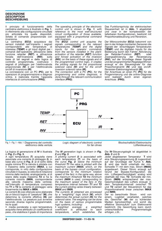
Das Funktionsprinzip der elektronischen Steuereinheit ist in Abb. 1 abgebildet und zwar in der komplexesten der lieferbaren Konfigurationen, bestückt mit Proportionalsteuerung und Reversion.
Der Mikrocontroller (ECU) bekommt von den in der Anlage montierten Sensoren die Signale der einschlägigen Temperaturen (TEMP) und die digitalen Inputs für die Bedienung durch den Fahrer: Aktivierung der Retarder-Funktion (RET) oder Zwangsaktivierung der Reversierung (INV); auf der Grundlage dieser Signale und der programmierten Regelalgorithmen erzeugt er die Steuersignale für das Proportionalventil (IV) und das on/off-Reversier-Elektromagnetventil (IR).Der Anschluss an einen PC (PC) für die Progammierung und die online-Diagnose wird realisiert durch einen eigenen Anschluss (PRG).
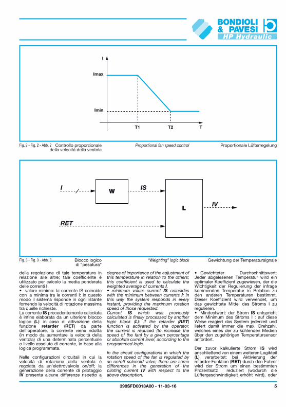
Die IV-Steuerungslogik ist abgebildet in Abb. 2 und 3.Jeder abgelesenen Temperatur T wird eine Steuerungsspannung (I) zugeordnet; auf der Grundlage der Kurve lt. Abb. 2: wird das Ventil unterhalb der min. Schwelle T1 mit dem max. Strom (IMAX) angesteuert. Dieser Strom erzeugt auf Grund der Bypass-Konfiguration die min. Lüftergeschwindigkeit; analog wird oberhalb der max. T2- Schwelle der min. Strom (IMIN) entsprechend der max. Geschwindigkeit des Lüfters erzeugt; in dem Temperaturintervall zwischen T1 und T2 variiert der Steuerstrom für das Proportionalventil linear zwischen IMAX und IMIN. Der so berechnete Strom wird von einem, Logikteil verarbeitet, welches die‚ Gewichte’ (W) der zu kühlenden Medien berücksichtigt, und somit die effektive Stromzufuhr zum Elektroventil bestimmt. Die Gewichtung kann durch unterschiedliche Programmierlogik erfolgen, z.B.:
Blockschaltbild Elektronische Lüftersteuerung
BESCHREIBUNG
The operating principle of the electronic control unit is shown in Fig. 1, with reference to the most well-structured circuit configuration of those available, equipped with a proportional command with inversion.The (ECU) control unit acquires the signals corresponding to the relevant temperatures (TEMP) and the digital inputs for the operator commands from the sensors installed in the plant: activation of the retarder (RET) function and forced activation of the inversion (INV); on the basis of these signals and of the programmed control logic, it creates the piloting signals for the proportional solenoid valve (IV) and for the on/off inversion solenoid valve (IR).The connection with a PC (PC), for the programming and online diagnosis, is done through the relevant communication interface (PRG).
The IV generation logic is shown in Fig. 2 and Fig. 3.A piloting current (I) is associated with each temperature (T) on the basis of the curve Fig. 2: below the minimum threshold T1 the valve is piloted with the maximum current (IMAX, which, on the basis of the bypass circuit configuration, corresponds to the minimum rotation speed of the fan); in the same way, above the maximum threshold T2 the minimum current (IMIN is used, corresponding to the maximum speed of the fan); in the temperature interval between T1 and T2 the current piloting varies linearly between IMAX and IMIN.The currents (I) obtained are processed by a “weighting” logic block (W), which determines the actual current (IS) for the solenoid valve. The weighting can be done on the basis of various programmable logic systems, including:• weighted average: a weighted coefficient is attributed to each temperature, which establishes the
Logic diagram of electronic controlfor fan drives
DESCRIPTION
Il principio di funzionamento della centralina elettronica è illustrato in Fig. 1, in riferimento alla configurazione circuitale più articolata tra quelle disponibili, dotata di comando proporzionale con inversione.La centralina (ECU) acquisisce dai sensori installati nell’impianto i segnali corrispondenti alle temperature di interesse (TEMP) e gli input digitali per i comandi dell’operatore: attivazione della funzione retarder (RET) e attivazione forzata dell’inversione (INV); sulla base di tali segnali e della logica di controllo programmata, costruisce i segnali di pilotaggio per l’elettrovalvola proporzionale (IV) e per l’elettrovalvola on/off di inversione (IR).La connessione con un PC (PC), per le operazioni di programmazione e diagnosi online, è realizzata tramite l’apposita interfaccia di comunicazione (PRG).
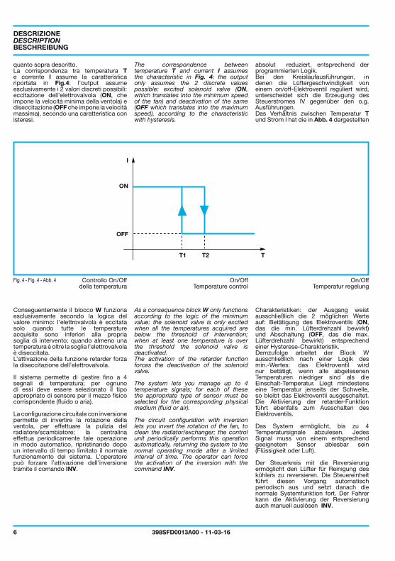
La logica di generazione di IV è illustrata in Fig. 2 e Fig. 3.A ogni temperatura (T) acquisita viene associata una corrente di pilotaggio (I), in base alla curva di Fig. 2: al di sotto della soglia minima T1 la valvola è pilotata con il massimo della corrente (IMAX, a cui corrisponde, in virtù della configurazione circuitale in bypass, la velocità di rotazione minima della ventola); analogamente, al di sopra della soglia massima T2 si ha la corrente minima (IMIN, corrispondente alla velocità massima della ventola); nell’intervallo di temperatura compreso tra T1 e T2 la corrente di pilotaggio varia linearmente tra IMAX e IMIN.Le correnti (I) così ottenute sono elaborate da un blocco logico di “pesatura” (W), che determina la corrente effettiva (IS) per l’elettrovalvola. La pesatura può avvenire secondo diverse logiche programmabili, tra le quali:• media ponderata: a ogni temperatura acquisita viene attribuito un coefficiente di peso, che stabilisce il grado di importanza
Diagramma del controlloelettronico della ventola
DESCRIZIONE
Fig. 1 - Fig. 1 - Abb. 1
I
T1 T2 T
Imax
Imin
L
I IS
RET
IV
W
5398SFD0013A00 - 11-03-16
Gewichtung der Temperatursignale
Proportionale Lüfterregelung
• Gewichteter Durchschnittswert: Jeder abgelesenen Temperatur wird ein optimaler Koeffizient zugewiesen, der die Wichtigkeit der Regulierung der infrage kommenden Temperatur in Relation zu den anderen Temperaturen bestimmt. Dieser Koeffizient wird verwendet, um das gewichtete Mittel des Stroms I zu regulieren. • Mindestwert: der Strom IS entspricht dem Minimum des Stroms I : auf diese Weise reagiert das System jederzeit und liefert damit immer die max. Drehzahl, welches eines der zu kühlenden Medien über den zugehörigen Temperatursensor anfordert.
Der zuvor kalkulierte Strom IS wird anschließend von einem weiteren Logikteil (L) verarbeitet: bei Aktivierung der retarder-Funktion (RET) durch den Fahrer wird der Strom um einen bestimmten Prozentsatz reduziert (wodurch die Lüftergeschwindigkeit erhöht wird), oder
“Weighting” logic block
Proportional fan speed control
degree of importance of the adjustment of this temperature in relation to the others; this coefficient is used to calculate the weighted average of currents I.• minimum value: current IS coincides with the minimum between currents I: in this way the system responds in every instant, providing the maximum rotation speed of those requested.Current IS which was previously calculated is finally processed by another logic block (L): if the retarder (RET) function is activated by the operator, the current is reduced (to increase the speed of the fan) by a given percentage or absolute current level, according to the programmed logic.
In the circuit configurations in which the rotation speed of the fan is regulated by an on/off solenoid valve; there are some differences in the generation of the piloting current IV with respect to the above description.
Blocco logicodi “pesatura”
Controllo proporzionaledella velocità della ventola
della regolazione di tale temperatura in relazione alle altre; tale coefficiente è utilizzato per calcolo la media ponderata delle correnti I.• valore minimo: la corrente IS coincide con la minima tra le correnti I: in questo modo il sistema risponde in ogni istante fornendo la velocità di rotazione massima tra quelle richieste.La corrente IS precedentemente calcolata è infine elaborata da un ulteriore blocco logico (L): in caso di attivazione della funzione retarder (RET) da parte dell’operatore, la corrente viene ridotta (in modo da aumentare la velocità della ventola) di una determinata percentuale o livello assoluto di corrente, in base alla logica programmata.
Nelle configurazioni circuitali in cui la velocità di rotazione della ventola è regolata da un’elettrovalvola on/off; la generazione della corrente di pilotaggio IV presenta alcune differenze rispetto a
Fig. 3 - Fig. 3 - Abb. 3
Fig. 2 - Fig. 2 - Abb. 2
I
T1 T2 T
ON
OFF
6 398SFD0013A00 - 11-03-16
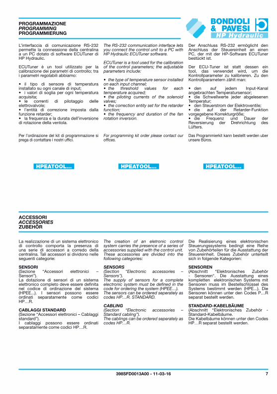
absolut reduziert, entsprechend der programmierten Logik.Bei den Kreislaufausführungen, in denen die Lüftergeschwindigkeit von einem on/off-Elektroventil reguliert wird, unterscheidet sich die Erzeugung des Steuerstromes IV gegenüber den o.g. Ausführungen.Das Verhältnis zwischen Temperatur T und Strom I hat die in Abb. 4 dargestellten
On/OffTemperatur regelung
Charakteristiken: der Ausgang weist ausschließlich die 2 möglichen Werte auf: Betätigung des Elektroventils (ON, das die min. Lüfterdrehzahl bewirkt) und Abschaltung (OFF, das die max. Lüfterdrehzahl bewirkt) entsprechend einer Hysterese-Charakteristik.Demzufolge arbeitet der Block W ausschließlich nach einer Logik des min.-Wertes: das Elektroventil wird nur betätigt, wenn alle abgelesenen Temperaturen niedriger sind als die Einschalt-Temperatur. Liegt mindestens eine Temperatur jenseits der Schwelle, so bleibt das Elektroventil ausgeschaltet. Die Aktivierung der retarder-Funktion führt ebenfalls zum Ausschalten des Elektroventils.
Das System ermöglicht, bis zu 4 Temperatursignale abzulesen. Jedes Signal muss von einem entsprechend geeignetem Sensor ablesbar sein (Flüssigkeit oder Luft).
Der Steuerkreis mit die Reversierung ermöglicht den Lüfter für Reinigung des kühlers zu reversieren. Die Steuereinheit führt diesen Vorgang automatisch periodisch aus und setzt danach die normale Systemfunktion fort. Der Fahrer kann die Aktivierung der Reversierung auch manuell auslösen INV.
BESCHREIBUNG
The correspondence between temperature T and current I assumes the characteristic in Fig. 4: the output only assumes the 2 discrete values possible: excited solenoid valve (ON, which translates into the minimum speed of the fan) and deactivation of the same (OFF which translates into the maximum speed), according to the characteristic with hysteresis.
On/OffTemperature control
As a consequence block W only functions according to the logic of the minimum value: the solenoid valve is only excited when all the temperatures acquired are below the threshold of intervention; when at least one temperature is over the threshold the solenoid valve is deactivated.The activation of the retarder function forces the deactivation of the solenoid valve.
The system lets you manage up to 4 temperature signals; for each of these the appropriate type of sensor must be selected for the corresponding physical medium (fluid or air).
The circuit configuration with inversion lets you invert the rotation of the fan, to clean the radiator/exchanger; the control unit periodically performs this operation automatically, returning the system to the normal operating mode after a limited interval of time. The operator can force the activation of the inversion with the command INV.
DESCRIPTION
quanto sopra descritto.La corrispondenza tra temperatura T e corrente I assume la caratteristica riportata in Fig.4: l’output assume esclusivamente i 2 valori discreti possibili: eccitazione dell’elettrovalvola (ON, che impone la velocità minima della ventola) e diseccitazione (OFF che impone la velocità massima), secondo una caratteristica con isteresi.
Controllo On/Offdella temperatura
Conseguentemente il blocco W funziona esclusivamente secondo la logica del valore minimo: l’elettrovalvola è eccitata solo quando tutte le temperature acquisite sono inferiori alla propria soglia di intervento; quando almeno una temperatura è oltre la soglia l’elettrovalvola è diseccitata.L’attivazione della funzione retarder forza la diseccitazione dell’elettrovalvola.
Il sistema permette di gestire fino a 4 segnali di temperatura; per ognuno di essi deve essere selezionato il tipo appropriato di sensore per il mezzo fisico corrispondente (fluido o aria).
La configurazione circuitale con inversione permette di invertire la rotazione della ventola, per effettuare la pulizia del radiatore/scambiatore; la centralina effettua periodicamente tale operazione in modo automatico, ripristinando dopo un intervallo di tempo limitato il normale funzionamento del sistema. L’operatore può forzare l’attivazione dell’inversione tramite il comando INV.
DESCRIZIONE
Fig. 4 - Fig. 4 - Abb. 4
7398SFD0013A00 - 11-03-16
HPEATOOL... HPEATOOL...HPEATOOL...
Der Anschluss RS-232 ermöglicht den Anschluss der Steuereinheit an einen PC, der mit der HP-Software ECUTuner bestückt ist.
Der ECU-Tuner ist statt dessen ein tool, das verwendet wird, um die Kontrollparameter zu kalibrieren. Zu den Kontrollparametern zählt man:
• den auf jedem Input-Kanal angebrachten Temperatursensor;• die Schwellwerte jeder abgelesenen Temperatur;• den Steuerstrom der Elektroventile;• die auf der Retarder-Funktion vorgegebene Korrekturgröße;• die Frequenz und Dauer der Reversierung der Drehrichtung des Lüfters.
Das Programmierkit kann bestellt werden uber unsere Büros.
PROGRAMMIERUNG
ZUBEHÖR
Die Realisierung eines elektronischen Steuerungssystems bedingt eine Reihe von Zubehörteilen für die Ausstattung der Steuereinheit. Dieses Zubehör unterteilt sich in folgende Kategorien:
SENSOREN (Abschnitt “Elektronisches Zubehör - Sensoren“. Die Ausstattung eines kompletten elektronischen Systems mit Sensoren muss im Bestellschlüssel des Systems bestimmt werden (HPE...). Die Sensoren können unter den Codes P…R separat bestellt werden.
STANDARD-KABELBÄUME(Abschnitt “Elektronisches Zubehör - Standard-Kabelbäume. Die Kabelbäume können unter den Codes HP…R separat bestellt werden.
The RS-232 communication interface lets you connect the control unit to a PC with HP Hydraulic ECUTuner software.
ECUTuner is a tool used for the calibration of the control parameters; the adjustable parameters include:
• the type of temperature sensor installed on each input channel;• the threshold values for each temperature acquired;• the piloting currents of the solenoid valves;• the correction entity set for the retarder function;• the frequency and duration of the fan rotation inversion.
For programming kit order please contact our offices.
PROGRAMMING
ACCESSORIES
The creation of an eletronic control system carries the presence of a series of accessories supplied with the control unit. These accessories are divided into the following categories:
SENSORS (Section “Electronic accessories – Sensors”).The supply of sensors for a complete electronic system must be defined in the code for ordering the system (HPEE…).The sensors can be ordered seperately as codes HP…R. STANDARD.
CABLING (Section “Electronic accessories – Standard cabling”).The cablings can be ordered seperately as codes HP…R.
L’interfaccia di comunicazione RS-232 permette la connessione della centralina a un PC dotato di software ECUTuner di HP Hydraulic.
ECUTuner è un tool utilizzato per la calibrazione dei parametri di controllo; tra i parametri regolabili abbiamo:
• il tipo di sensore di temperatura installato su ogni canale di input;• i valori di soglia per ogni temperatura acquisita;• le correnti di pilotaggio delle elettrovalvole;• l’entità di correzione imposta dalla funzione retarder;• la frequenza e la durata dell’inversione di rotazione della ventola.
Per l’ordinazione del kit di programmazione si prega di contattare i nostri uffici.
PROGRAMMAZIONE
ACCESSORI
La realizzazione di un sistema elettronico di controllo comporta la presenza di una serie di accessori a corredo della centralina. Tali accessori si dividono nelle seguenti categorie:
SENSORI (Sezione “Accessori elettronici – Sensori”).La dotazione di sensori di un sistema elettronico completo deve essere definita nel codice di ordinazione del sistema (HPEE...). I sensori possono essere ordinati separatamente come codici HP…R.
CABLAGGI STANDARD (Sezione “Accessori elettronici – Cablaggi standard”).I cablaggi possono essere ordinati separatamente come codici HP…R.
C
A
B
8 7 6 5 4 3 2 1
130
110
110
18
16.4
5
R9
1035
4
24
44.15
8 398SFD0013A00 - 11-03-16
PIN
5A4C4B4A3C3B8B8A1B1A2A6C6B7B7A7C8C1C
ELEKTRONISCHE BAUELEMENTE
ELEKTRONISCHE STEUEREINHEIT
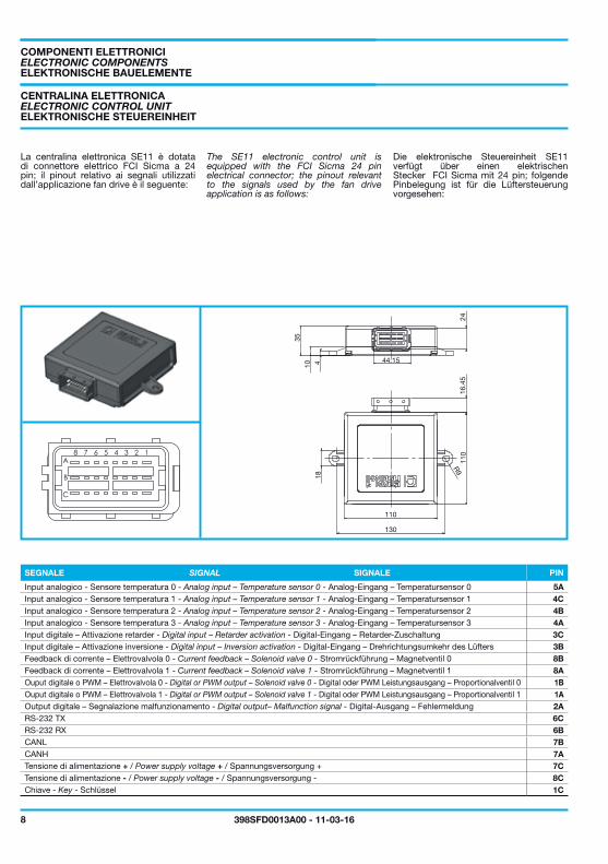
Die elektronische Steuereinheit SE11 verfügt über einen elektrischen Stecker FCI Sicma mit 24 pin; folgende Pinbelegung ist für die Lüftersteuerung vorgesehen:
SIGNALE
ELECTRONIC COMPONENTS
ELECTRONIC CONTROL UNIT
The SE11 electronic control unit is equipped with the FCI Sicma 24 pin electrical connector; the pinout relevant to the signals used by the fan drive application is as follows:
SIGNAL
La centralina elettronica SE11 è dotata di connettore elettrico FCI Sicma a 24 pin; il pinout relativo ai segnali utilizzati dall’applicazione fan drive è il seguente:
COMPONENTI ELETTRONICI
CENTRALINA ELETTRONICA
SEGNALE
Input analogico - Sensore temperatura 0 - Analog input – Temperature sensor 0 - Analog-Eingang – Temperatursensor 0
Chiave - Key - SchlüsselTensione di alimentazione - / Power supply voltage - / Spannungsversorgung -Tensione di alimentazione + / Power supply voltage + / Spannungsversorgung +CANHCANLRS-232 RXRS-232 TXOutput digitale – Segnalazione malfunzionamento - Digital output– Malfunction signal - Digital-Ausgang – FehlermeldungOuput digitale o PWM – Elettrovalvola 1 - Digital or PWM output – Solenoid valve 1 - Digital oder PWM Leistungsausgang – Proportionalventil 1Ouput digitale o PWM – Elettrovalvola 0 - Digital or PWM output – Solenoid valve 0 - Digital oder PWM Leistungsausgang – Proportionalventil 0Feedback di corrente – Elettrovalvola 1 - Current feedback – Solenoid valve 1 - Stromrückführung – Magnetventil 1Feedback di corrente – Elettrovalvola 0 - Current feedback – Solenoid valve 0 - Stromrückführung – Magnetventil 0Input digitale – Attivazione inversione - Digital input – Inversion activation - Digital-Eingang – Drehrichtungsumkehr des LüftersInput digitale – Attivazione retarder - Digital input – Retarder activation - Digital-Eingang – Retarder-ZuschaltungInput analogico - Sensore temperatura 3 - Analog input – Temperature sensor 3 - Analog-Eingang – Temperatursensor 3Input analogico - Sensore temperatura 2 - Analog input – Temperature sensor 2 - Analog-Eingang – Temperatursensor 2Input analogico - Sensore temperatura 1 - Analog input – Temperature sensor 1 - Analog-Eingang – Temperatursensor 1
9398SFD0013A00 - 11-03-16
HP554030001R
HP268010002R
HP268010004R
TEMPERATURSENSOREN
Folgende Temperatursensoren stehen für die Kühlsysteme zur Verfügung:
BESTELL-NR. BESCHREIBUNG
Temperatursensor für Wasser, Öl und Luft
(siehe Abschnitt “Elektronisches Zubehör - Sensoren”, 20).
VERKABELUNG
Für die Verkabelung der Lüftersteuerung steht folgender Standard-Kabelbaum zur Verfügung:
BESTELL-NR. BESCHREIBUNG
Standard-Kabelbaum für Lüftersteuerung, stecker DIN
Kabelbaum für Lüftersteuerung stecker DEUTSCH
(siehe Abschnitt “Elektronisches Zubehör - Verkabelung”, 22).
Bei abweichender Konfiguration wenden Sie sich bitte an HP Hydraulic - Bondioli & Pavesi.
TEMPERATURE SENSORS
The sensors available for the acquisition of the temperature from the system are of the following type:
CODE DESCRIPTION
Temperature sensor for air, water, oil
(See section “Electronic accessories - Sensors”, page 20).
WIRING SYSTEM
The following standard wiring systems are available for the application of the fan drive control:
CODE DESCRIPTION
Standard wiring harness for fan drive application, DIN connector
Wiring harness for fan drive application DEUTSCH
(See section “Electronic accessories - Standard wiring”, 22).
For dedicated configurations, contact HP Hydraulic - Bondioli & Pavesi customer service.
I sensori disponibili per l’acquisizione di temperatura dal sistema sono del seguente tipo:
SENSORI DI TEMPERATURA
CODICE DESCRIZIONE
Sensore di temperatura per aria, acqua, olio
(Vedere la sezione “Accessori elettronici - Sensori”, pag. 20).
CABLAGGIO
Per l’applicazione di controllo fan drive è disponibile il seguente cablaggio standard:
CODICE DESCRIZIONE
Cablaggio standard per applicazione fan drive, connettore DIN
Cablaggio per applicazione fan drive connettore DEUTSCH
(Vedere sezione “Accessori elettronici - Cablaggi standard”, pag. 22).
Per eventuali configurazioni dedicate, contattare il servizio clienti di HP Hydraulic - Bondioli & Pavesi.
10 398SFD0013A00 - 11-03-16
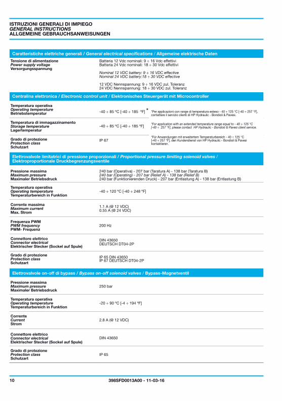
-40 ÷ 85 ºC [-40 ÷ 185 ºF]
IP 67
-40 ÷ 85 ºC [-40 ÷ 185 ºF] *
-40 ÷ 120 ºC [-40 ÷ 248 ºF]
1.1 A (@ 12 VDC)0.55 A (@ 24 VDC)
200 Hz
IP 65 DIN 43650IP 67 DEUTSCH DT04-2P
250 bar
-20 ÷ 90 ºC [-4 ÷ 194 ºF]
2.8 A (@ 12 VDC)
IP 65
DEUTSCH DT04-2P DIN 43650
DIN 43650
ALLGEMEINE GEBRAUCHSANWEISUNGEN
Versorgungsspannung
12 VDC Nennspannung: 9 ÷ 16 VDC zul. Toleranz24 VDC Nennspannung: 18 ÷ 30 VDC zul. Toleranz
Betriebstemperatur
Lagertemperatur
Schutzart
Maximaler Betriebsdruck
Temperaturbereich in Funktion
Max. Strom
PWM- Frequenz
Elektrischer Stecker (Sockel auf Spule)
Schutzart
240 bar (Funktionierenden Druck) - 207 bar (Entlastung A) - 138 bar (Entlastung B)
Maximaler Betriebsdruck
Temperaturbereich in Funktion
Strom
Elektrischer Stecker (Sockel auf Spule)
Schutzart
*Für Anwendungen mit erweitertem Temperaturbereich - 40 ÷ 125 °C [-40 ÷ 257 °F], den Kundendienst von HP Hydraulic - Bondioli & Pavesikontaktieren.
GENERAL INSTRUCTIONS
Power supply voltage
Nominal 12 VDC battery: 9 ÷ 16 VDC effectiveNominal 24 VDC battery:18 ÷ 30 VDC effective
Operating temperature
Storage temperature
Protection class
Maximum pressure
Operating temperature
Maximum current
PWM frequency
Connector electrical
Protection class
240 bar (Operating) - 207 bar (Relief A) - 138 bar (Relief B)
Maximum pressure
Operating temperature
Current
Connector electrical
Protection class
*For application with an extended temperature range equal to - 40 ÷ 125 °C [-40 ÷ 257 °F], please contact HP Hydraulic - Bondioli & Pavesi client service.
ISTRUZIONI GENERALI DI IMPIEGO
Tensione di alimentazione Batteria 12 Vdc nominali: 9 ÷ 16 Vdc effettiviBatteria 24 Vdc nominali: 18 ÷ 30 Vdc effettivi
Temperatura operativa
Temperatura di immagazzinamento
Grado di protezione
Pressione massima 240 bar (Operativa) - 207 bar (Taratura A) - 138 bar (Taratura B)
Temperatura operativa
Corrente massima
Frequenza PWM
Connettore elettrico
Grado di protezione
Pressione massima
Temperatura operativa
Corrente
Connettore elettrico
Grado di protezione
*Per applicazioni con range di temperatura esteso - 40 ÷ 125 °C [-40 ÷ 257 °F], contattare il servizio clienti di HP Hydraulic - Bondioli & Pavesi.
Caratteristiche elettriche generali / General electrical specifications / Allgemeine elektrische Daten
Elettrovalvole limitatrici di pressione proporzionali / Proportional pressure limiting solenoid valves /Elektroproportionale Druckbegrenzungsventile
Centralina elettronica / Electronic control unit / Elektronisches Steuergerät mit Microcontroller
Elettrovalvole on-off di bypass / Bypass on-off solenoid valves / Bypass-Magnetventil
11398SFD0013A00 - 11-03-16
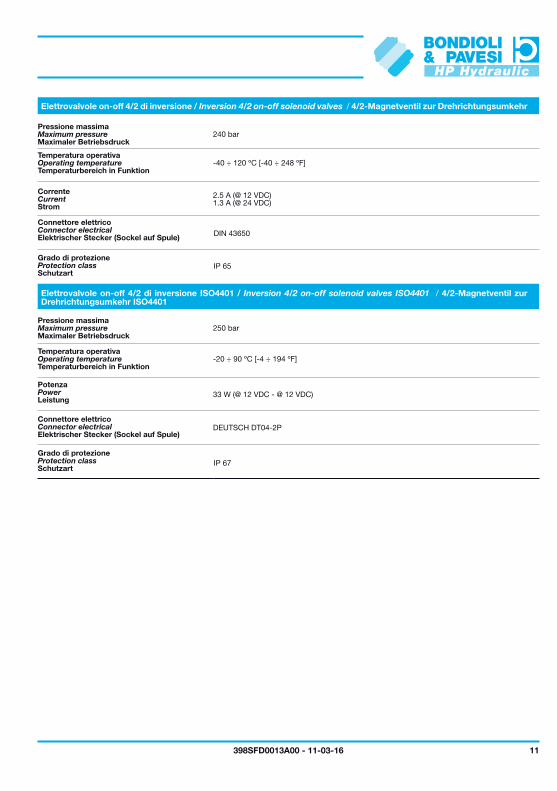
250 bar
240 bar
-20 ÷ 90 ºC [-4 ÷ 194 ºF]
-40 ÷ 120 ºC [-40 ÷ 248 ºF]
33 W (@ 12 VDC - @ 12 VDC)
2.5 A (@ 12 VDC)1.3 A (@ 24 VDC)
DEUTSCH DT04-2P
DIN 43650
IP 65
IP 67
Maximaler Betriebsdruck
Maximaler Betriebsdruck
Temperaturbereich in Funktion
Temperaturbereich in Funktion
Leistung
Strom
Elektrischer Stecker (Sockel auf Spule)
Elektrischer Stecker (Sockel auf Spule)
Schutzart
Schutzart
Maximum pressure
Maximum pressure
Operating temperature
Operating temperature
Power
Current
Connector electrical
Connector electrical
Protection class
Protection class
Pressione massima
Pressione massima
Temperatura operativa
Temperatura operativa
Potenza
Corrente
Connettore elettrico
Connettore elettrico
Grado di protezione
Grado di protezione
Elettrovalvole on-off 4/2 di inversione ISO4401 / Inversion 4/2 on-off solenoid valves ISO4401 / 4/2-Magnetventil zur Drehrichtungsumkehr ISO4401
Elettrovalvole on-off 4/2 di inversione / Inversion 4/2 on-off solenoid valves / 4/2-Magnetventil zur Drehrichtungsumkehr

F2 E2
B2
[4.7
56]
120.
8
[6.7
24]
170.
8
[1.409]35.8 A2
[3.9
37]
100
[0.6
1]15
.5
[3.504]89
12 398SFD0013A00 - 11-03-16
A2 B2
mm in mm in
2
05 49,15 1,935 24,6 0,968
06 51,85 2,041 25,9 1,021
08 56,35 2,219 28,2 1,109
11 60,85 2,396 30,4 1,198
14 67,25 2,648 33,6 1,324
17 71,75 2,825 35,9 1,412
20 76,25 3,002 38,1 1,501
26 88,55 3,486 44,3 1,743
V1
V1
VERSION
KONFIGURATION “V1”: MOTOR MIT S/W-MAGNETVENTIL, MAX.DBV UND NACHSAUGVENTIL
Drehzahl Brennkraftmaschine
Lüft
erd
rehz
ahl
E2 = siehe Abschnitt “Flansche”F2 = siehe Abschnitt “Wellenende”
ABMESSUNGEN
BAUREIHE TYP
VERSIONS
“V1” CONFIGURATION: ON-OFF WITH ANTICAVITATION
Endothermic motor speed
Fan
sp
eed
E2 = See flange sectionF2 = See shafts profile
SIZE
GROUP TYPE
VERSIONI
CONFIGURAZIONE “V1”: ON-OFF CON ANTICAVITAZIONE
Velocità motore endotermico
Velo
cità
ven
tola
E2 = Vedi sezione flangeF2 = Vedi profilo alberi
DIMENSIONI
GRUPPO TIPO
A2 F2 E2
B2
[3.9
37]
100
[1.614]41
[1.409]35.8
[0.6
1]15
.5
[3.504]89
[4.13]104.9
250
200
150
100
50
00 10 20 40 5030 70 80 90 10060
3500
3000
2500
2000
1500
1000
500
0
AB
00
25
50
75
100
125
0
25
50
75
100
125
20 40 60 80 100
0 5 10 15 20 25
0 Current
50% Max. Control Current
75% Max. Control Current
100% Max. Control Current
13398SFD0013A00 - 11-03-16
A2 B2
mm in mm in
2
05 49,15 1,935 24,6 0,968
06 51,85 2,041 25,9 1,021
08 56,35 2,219 28,2 1,109
11 60,85 2,396 30,4 1,198
14 67,25 2,648 33,6 1,324
17 71,75 2,825 35,9 1,412
20 76,25 3,002 38,1 1,501
26 88,55 3,486 44,3 1,743
bar psi
200 Hz PWM
gpm
l/min
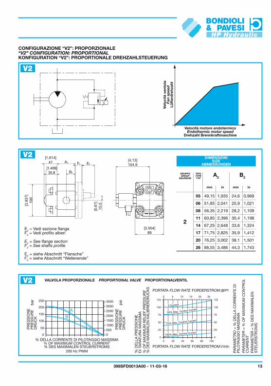
V2
V2
V2
KONFIGURATION “V2”: PROPORTIONALE DREHZAHLSTEUERUNG
Drehzahl Brennkraftmaschine
Lüft
erd
rehz
ahl
ABMESSUNGEN
BAUREIHE TYP
DR
UC
K
DR
UC
K
% DES MAXIMALEN STEUERSTROMS
PROPORTIONALVENTIL
FORDERSTROM
FORDERSTROM
% D
ES M
AXI
MA
LEN
KA
LIB
RIE
RD
RU
CK
S
PAR
AM
ETE
R =
% D
ES
MA
XIM
ALE
N
STE
UE
RS
TRO
MS
E2 = siehe Abschnitt “Flansche”F2 = siehe Abschnitt “Wellenende”
“V2” CONFIGURATION: PROPORTIONAL
Endothermic motor speed
Fan
sp
eed
SIZE
GROUP TYPE
PR
ES
SU
RE
PR
ES
SU
RE
% OF MAXIMUM CONTROL CURRENT
PROPORTIONAL VALVE
FLOW RATE
FLOW RATE
% O
F M
AX
IMU
M R
ELI
EF
PR
ES
SU
RE
PAR
AM
ETE
R =
% O
F M
AX
IMU
M C
ON
TRO
L C
UR
RE
NT
E2 = See flange sectionF2 = See shafts profile
CONFIGURAZIONE “V2”: PROPORZIONALE
Velocità motore endotermico
Velo
cità
ven
tola
DIMENSIONI
GRUPPO TIPO
PR
ES
SIO
NE
PR
ES
SIO
NE
% DELLA CORRENTE DI PILOTAGGIO MASSIMA
VALVOLA PROPORZIONALE
PORTATA
PORTATA
% D
ELL
A P
RE
SS
ION
E
DI T
AR
ATU
RA
MA
SS
IMA
PAR
AM
ETR
O =
% D
ELL
A C
OR
RE
NTE
DI
PIL
OTA
GG
IO M
AS
SIM
A
E2 = Vedi sezione flangeF2 = Vedi profilo alberi
A2 B2
mm in mm in
2
05 49,15 1,935 24,6 0,968
06 51,85 2,041 25,9 1,021
08 56,35 2,219 28,2 1,109
11 60,85 2,396 30,4 1,198
14 67,25 2,648 33,6 1,324
17 71,75 2,825 35,9 1,412
20 76,25 3,002 38,1 1,501
26 88,55 3,486 44,3 1,743
A2 F2 E2
B2
[3.9
37]
100
[2.205]56
[0.6
1]15
.5
[3.504]89
[4.13]104.9
250
200
150
100
50
00 10 20 40 5030 70 80 90 10060
3500
3000
2500
2000
1500
1000
500
0
AB
00
25
50
75
100
125
0
25
50
75
100
125
20 40 60 80 100
0 5 10 15 20 25
0 Current
50% Max. Control Current
75% Max. Control Current
100% Max. Control Current
14 398SFD0013A00 - 11-03-16
bar psi
200 Hz PWM
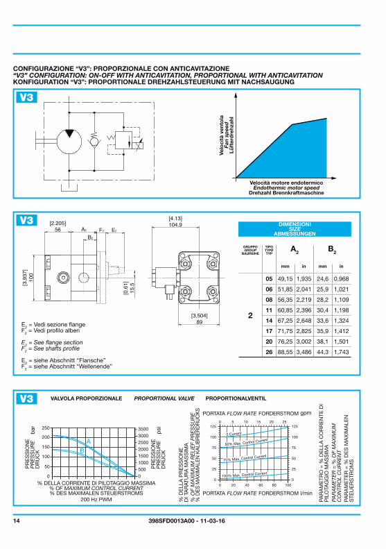
V3
V3
V3gpm
l/min
ABMESSUNGEN
BAUREIHE TYP
KONFIGURATION “V3”: PROPORTIONALE DREHZAHLSTEUERUNG MIT NACHSAUGUNG
Drehzahl Brennkraftmaschine
Lüft
erd
rehz
ahl
DR
UC
K
DR
UC
K
% DES MAXIMALEN STEUERSTROMS
PROPORTIONALVENTIL
% D
ES M
AXI
MA
LEN
KA
LIB
RIE
RD
RU
CK
S
PAR
AM
ETE
R =
% D
ES
MA
XIM
ALE
N
STE
UE
RS
TRO
MS
E2 = siehe Abschnitt “Flansche”F2 = siehe Abschnitt “Wellenende”
FORDERSTROM
FORDERSTROM
SIZE
GROUP TYPE
“V3” CONFIGURATION: ON-OFF WITH ANTICAVITATION, PROPORTIONAL WITH ANTICAVITATION
Endothermic motor speed
Fan
sp
eed
PR
ES
SU
RE
PR
ES
SU
RE
% OF MAXIMUM CONTROL CURRENT
PROPORTIONAL VALVE
% O
F M
AX
IMU
M R
ELI
EF
PR
ES
SU
RE
PAR
AM
ETE
R =
% O
F M
AX
IMU
M
CO
NTR
OL
CU
RR
EN
TE2 = See flange sectionF2 = See shafts profile
FLOW RATE
FLOW RATE
DIMENSIONI
GRUPPO TIPO
CONFIGURAZIONE “V3”: PROPORZIONALE CON ANTICAVITAZIONE
Velocità motore endotermico
Velo
cità
ven
tola
PR
ES
SIO
NE
PR
ES
SIO
NE
% DELLA CORRENTE DI PILOTAGGIO MASSIMA
VALVOLA PROPORZIONALE
% D
ELL
A P
RE
SS
ION
E
DI T
AR
ATU
RA
MA
SS
IMA
PAR
AM
ETR
O =
% D
ELL
A C
OR
RE
NTE
DI
PIL
OTA
GG
IO M
AS
SIM
AE2 = Vedi sezione flangeF2 = Vedi profilo alberi
PORTATA
PORTATA
F2 A2E2
[5.34]135.8
[5.82]147.8
[1.87]47.5
[2.07]52.5
[2.73]69.3
[3.9
8]10
1
[1.9
7]50 [0
.41]
10.5
[2.9
9]76
[1.8
1]46 [1.2
8]32
.5
15398SFD0013A00 - 11-03-16
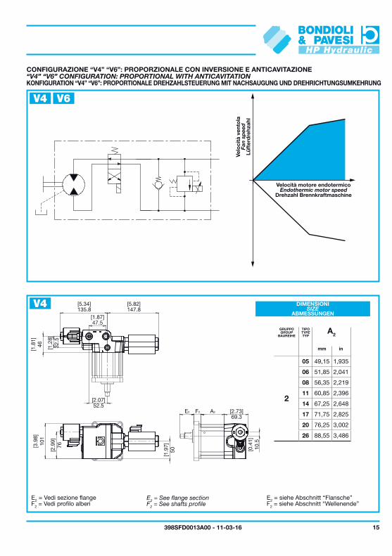
A2
mm in
2
05 49,15 1,935
06 51,85 2,041
08 56,35 2,219
11 60,85 2,396
14 67,25 2,648
17 71,75 2,825
20 76,25 3,002
26 88,55 3,486
V4
V4
V6
KONFIGURATION “V4” “V6”: PROPORTIONALE DREHZAHLSTEUERUNG MIT NACHSAUGUNG UND DREHRICHTUNGSUMKEHRUNG
ABMESSUNGEN
BAUREIHE TYP
Drehzahl Brennkraftmaschine
Lüft
erd
rehz
ahl
E2 = siehe Abschnitt “Flansche”F2 = siehe Abschnitt “Wellenende”
“V4” “V6” CONFIGURATION: PROPORTIONAL WITH ANTICAVITATION
SIZE
GROUP TYPE
Endothermic motor speed
Fan
sp
eed
E2 = See flange sectionF2 = See shafts profile
CONFIGURAZIONE “V4” “V6”: PROPORZIONALE CON INVERSIONE E ANTICAVITAZIONE
DIMENSIONI
GRUPPO TIPO
Velocità motore endotermico
Velo
cità
ven
tola
E2 = Vedi sezione flangeF2 = Vedi profilo alberi
250
200
150
100
50
00 10 20 40 5030 70 80 90 10060
3500
3000
2500
2000
1500
1000
500
0
AB
00
25
50
75
100
125
0
25
50
75
100
125
20 40 60 80 100
0 5 10 15 20 25
0 Current
50% Max. Control Current
75% Max. Control Current
100% Max. Control Current
[6.29]159.8
[3.7]94.1
[2.41]61.3
[1.5]38
[0.49]12.4
[4.1
3]10
5
[6.8
2]17
3.3
[0.2
2]5.
5[2
.5]
63.5
[0.51]13
[1.24]31.5
[0.9
6]24
.5[1
.5]
38
F2 A2E2
16 398SFD0013A00 - 11-03-16
bar psi
200 Hz PWM
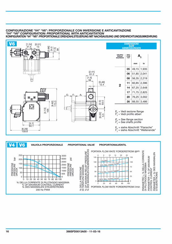
V4 V6
A2
mm in
2
05 49,15 1,935
06 51,85 2,041
08 56,35 2,219
11 60,85 2,396
14 67,25 2,648
17 71,75 2,825
20 76,25 3,002
26 88,55 3,486
V6
gpm
l/min
DR
UC
K
DR
UC
K
% DES MAXIMALEN STEUERSTROMS
PROPORTIONALVENTIL
% D
ES M
AXI
MA
LEN
KA
LIB
RIE
RD
RU
CK
S
PAR
AM
ETE
R =
% D
ES
MA
XIM
ALE
N
STE
UE
RS
TRO
MS
KONFIGURATION “V4” “V6”: PROPORTIONALE DREHZAHLSTEUERUNG MIT NACHSAUGUNG UND DREHRICHTUNGSUMKEHRUNG
ABMESSUNGEN
BAUREIHE TYP
E2 = siehe Abschnitt “Flansche”F2 = siehe Abschnitt “Wellenende”
FORDERSTROM
FORDERSTROM
PR
ES
SU
RE
PR
ES
SU
RE
% OF MAXIMUM CONTROL CURRENT
PROPORTIONAL VALVE
% O
F M
AX
IMU
M R
ELI
EF
PR
ES
SU
RE
PAR
AM
ETE
R =
% O
F M
AX
IMU
M
CO
NTR
OL
CU
RR
EN
T
“V4” “V6” CONFIGURATION: PROPORTIONAL WITH ANTICAVITATION
SIZE
GROUP TYPE
E2 = See flange sectionF2 = See shafts profile
FLOW RATE
FLOW RATE
PR
ES
SIO
NE
PR
ES
SIO
NE
% DELLA CORRENTE DI PILOTAGGIO MASSIMA
VALVOLA PROPORZIONALE
% D
ELL
A P
RE
SS
ION
E
DI T
AR
ATU
RA
MA
SS
IMA
PAR
AM
ETR
O =
% D
ELL
A C
OR
RE
NTE
D
I PIL
OTA
GG
IO M
AS
SIM
A
CONFIGURAZIONE “V4” “V6”: PROPORZIONALE CON INVERSIONE E ANTICAVITAZIONE
DIMENSIONI
GRUPPO TIPO
E2 = Vedi sezione flangeF2 = Vedi profilo alberi
PORTATA
PORTATA
18.95
00
1.7/25
3.4/50
6.9/100
5.2/100
8.6/125
10.3/150
37.910
50.815
12.0/175
13.7/200
18.95
1.7/25
3.4/50
6.9/100
5.2/100
8.6/125
10.3/150
37.910
50.815
12.0/175
13.7/200
00
17398SFD0013A00 - 11-03-16
V4
V6
l/min - gpm
l/min - gpm
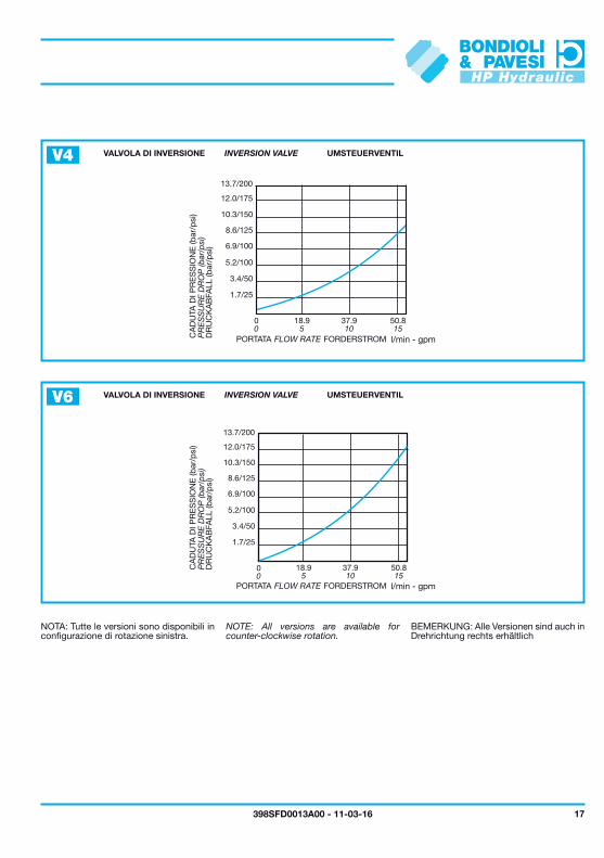
UMSTEUERVENTIL
UMSTEUERVENTIL
DR
UC
KA
BFA
LL (b
ar/p
si)
DR
UC
KA
BFA
LL (b
ar/p
si)
FORDERSTROM
FORDERSTROM
BEMERKUNG: Alle Versionen sind auch in Drehrichtung rechts erhältlich
INVERSION VALVE
INVERSION VALVE
PR
ES
SU
RE
DR
OP
(bar
/psi
)P
RE
SS
UR
E D
RO
P (b
ar/p
si)
FLOW RATE
FLOW RATE
NOTE: All versions are available for counter-clockwise rotation.
VALVOLA DI INVERSIONE
VALVOLA DI INVERSIONE
CA
DU
TA D
I PR
ES
SIO
NE
(bar
/psi
)C
AD
UTA
DI P
RE
SS
ION
E (b
ar/p
si)
PORTATA
PORTATA
NOTA: Tutte le versioni sono disponibili in configurazione di rotazione sinistra.
18 398SFD0013A00 - 11-03-16
05 4,5006 6,0008 8,5011 11,0014 14,5017 17,0020 19,5026 26,00
V - Viton
B - NBR
5......8 11 14......20 26
E3 E3 E5 E3 E5 E5 M2G4 G4 G6 G4 G6 G6 G3X5 X4 X6 X4 X6 X4 X6 X5 M2U6 U5 U6 U5 U6 U5 U3
HPL MA 2 11 B L G4 G4M B V4 B
I = DIN 43650D = DEUTSCH
A I
A=207 [bar] B=138 [bar] C=227 [bar]
B = 12 VDCC = 24 VDC
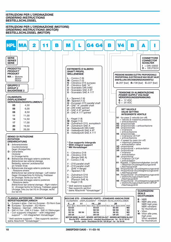
BESTELLSCHLÜSSEL (MOTOR)
BESTELLSCHLÜSSEL
SERIE
PRODUKT
Motor
BAUGRÖSSE 2
VERDRÄNGUNGSVOLUMEN/U
DREHRICHTUNG
WELLENENDE
L - Kegel (1:8)M - Kegel (1:5)N - Zylindrisch D15, europäischP - Zylindrisch SAE AU - Vielkeilprofil DIN 5482V - Vielkeilprofil SAE A 9TX - Vielkeilprofil SAE A 11T
* Mit Vorsatzlager
* siehe Abschnitt “Vorsatzlager”
1 - Zylindrisch D183 - Zylindrisch D18 (Flansch SAE A)7 - Kegel (1:8)
INTEGRIERTE VENTILE
V1 -Bypass, 2 Geschwindigkeiten (on/off) + Maximal-Druckbegrenzungsventil + NachsaugventilV2 - Proportional- DruckbegrenzungsventilV3 - Proportional-Druckbegrenzungsventil + NachsaugventilV4 - Proportional- Druckbegrenzungsventil + Drehrichtungsumkehrventil +NachsaugventilV6 - Proportional- Druckbegrenzungsventil + Drehrichtungsumkehrventil CETOP +Nachsaugventil
DICHTUNGEN
SCHALTER
EINSTELLUNG DRUCKBEGRENZUNGSVENTILE
VERSORGUNGSSPANNUNG
NBR verstärkt für Hochdruck
Viton verstärkt für Hochdruck
ORDERING INSTRUCTIONS (MOTOR)
ORDERING INSTRUCTIONS
SERIES
PRODUCT
Motor
GROUP 2
DISPLACEMENT
ROTATION
SHAFT PROFIL
L - Tapered (1:8)M - Tapered (1:5)N - European D15 parallel shaftP - SAE “A” parallel shaftU - DIN 5482 splinedV - SAE A 9T splinedX - SAE A 11T splined
* With integral support
1 - D18 parallel shaft3 - D18 parallel shaft (SAE A flange)7 - Tapered (1:8)
* See supports section
VALVE SETTING
V1 - 2 speed by-pass (on-off) + maximum pressure + anticavitation valveV2 - proportionalV3 - proportional + anticavitationV4 - proportional + inversion + anticavitationV6 - proportional + inversion CETOP + anticavitation
SEALS
NBR high pres.
high pres
CONNECTOR
PROPORTIONAL ELECTRICVALVE MAX RELIEF VALVE
POWER SUPPLY VOLTAGE
ISTRUZIONI PER L’ORDINAZIONE (MOTORE)
ISTRUZIONI PER L’ORDINAZIONE
SERIE
PRODOTTO
MA = Motore
GRUPPO 2
CILINDRATA
SENSO DI ROTAZIONE
ESTREMITÀ D’ALBERO
L - Conico (1:8)M - Conico (1:5)N - Cilindrico D15 europeoP - Cilindrico SAE “A”U - Scanalato DIN 5482V - Scanalato SAE A 9TX - Scanalato SAE A 11T
* Con supporto intergrale
1 - Cilindrico D183 - Cilindrico D18 (flangia SAE A)7 - Conico (1:8)
* Vedi sezione supporti
SET VALVOLE
V1 - by-pass 2 velocità (on-off) + valvola di massima pressione + anticavitazioneV2 - proporzionaleV3 - proporzionale + anticavitazione
GUARNIZIONI
W - Viton alte pres.
R - NBR alte pres.
CONNETTORE
PRESSIONE MASSIMA ELETTRV. PROPORZIONALE
TENSIONE DI ALIMENTAZIONE
V4 - proporzionale + inversione + anticavitazioneV6 - proporzionale + inversione CETOP + anticavitazione
S - Antioraria/sinistra Counterclockwise Gegen Uhrzeiger/linksD - Oraria/destra Clockwise Im Uhrzeiger/rechtsB - Bidirezionale drenaggio esterno posteriore Bidirectional rear external drainage Beidseitig, externer Leckölanschluß am hinteren EndeL - Bidirezionale drenaggio esterno posteriore - Rotazione sinistra Bidirectional rear external drainage – Left rotation Gegen Uhrzeiger/links für Kühlung, Freiblasen im Uhrzeiger, rechts (nur bei V4)R - Bidirezionale drenaggio esterno posteriore - Rotazione destra Bidirectional rear external drainage – Right rotation Im Uhrzeiger/rechts für Kühlung, Freiblasen gegen Uhrzeiger, links (nur bei V4) im Uhrzeiger, rechts (nur bei V4)
L - Europea in ghisa - Cast iron European - EU-Norm GussM - Europea - European - EU-NormN - Tedesca - German - DIN-NormS - SAE A 2 fori - SAE A 2 holes - SAE A 2 BohrungenI - Con supporto integrato* - with integrated support * - mit integriertem Vorsatzlager*
* Vedi sezione supporti - * See supports section - siehe Abschnitt “Vorsatzlager” -
BOCCHE STD - STANDARD PORTS - STANDARD ANSCHLÜSSECILINDRATA - DISPLACEMENT - FÖRDER-/SCHLUCKVOLUMEN
Motori – Motors – Motoren OUT/IN Motori – Motors – Motoren OUT/IN Motori – Motors – Motoren OUT/IN DRAIN
FLANGIA ANTERIORE - FRONT FLANGEBEFESTIGUNGSFLANSCH
MOTORI BIDIR. IN=OUT - REVERS. MOTORS IN=OUT - BIDIREK.MOTOREN IN=OUTBocche STD - standard ports - standard Anschlüsse per - for - für V1-V2-V3
Bocche - ports - Anschlüsse G4 G4 / U6 U6 per - for - für V4-V6
19398SFD0013A00 - 11-03-16
HPE E 11 B 01 000FDR
B = 12 VDCC = 24 VDC
000
01 Standard
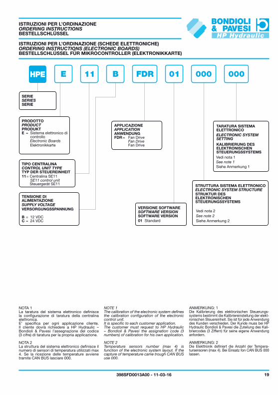
BESTELLSCHLÜSSEL
BESTELLSCHLÜSSEL FÜR MIKROCONTROLLER (ELEKTRONIKKARTE)
SERIE
PRODUKT
Elektronikkarte
Steuergerät SE11
ANWENDUNG
Fan Drive
TYP DER STEUEREINHEIT
VERSORGUNGSSPANNUNG
KALIBRIERUNG DES ELEKTRONISCHEN STEUERUNGSSYSTEMS
Siehe Anmerkung 1
STRUKTUR DES ELEKTRONISCHEN STEUERUNGSSYSTEMS
Siehe Anmerkung 2
ANMERKUNG: 1Die Kalibrierung des elektronischen Steuerungs-systems bestimmt die Kalibriereinstellung der elekt-ronischen Steuereinheit. Sie ist für jede Anwendung des Kunden verschieden. Der Kunde muss bei HP Hydraulic Bondioli & Pavesi die Zuteilung des Kali-briercodes (3 Ziffern) für seine eigene Anwendung anfordern.
ANMERKUNG: 2Die Elekttronik definiert die Anzahl der Tempera-tursensoren (max 4). Bei Einsatz fon CAN BUS 000 lassen.
SOFTWARE VERSION
ORDERING INSTRUCTIONS
ORDERING INSTRUCTIONS (ELECTRONIC BOARDS)
SERIES
PRODUCT
Electronic Boards
SE11 control unit
APPLICATION
Fan Drive
CONTROL UNIT TYPE
SUPPLY VOLTAGE
ELECTRONIC SYSTEM SETTING
See note 1
ELECTRONIC SYSTEM STRUCTURE
See note 2
NOTE 1The calibration of the electronic system defines the calibration configuration of the electronic control unit.It is specific to each customer application.The customer must request to HP Hydraulic – Bondioli & Pavesi the assignation code (3 numbers) of calibration for his own application.
NOTE 2Temperature sensors number (max 4) is function of the electronic system layout. If the capture of temperature came trough CAN BUS use 000.
SOFTWARE VERSION
ISTRUZIONI PER L’ORDINAZIONE
ISTRUZIONI PER L’ORDINAZIONE (SCHEDE ELETTRONICHE)
SERIE
PRODOTTO
E = Sistema elettronico di controllo
11 = Centralina SE11
TIPO CENTRALINA
APPLICAZIONE
FDR = Fan Drive
TENSIONE DI ALIMENTAZIONE
TARATURA SISTEMA ELETTRONICO
Vedi nota 1
STRUTTURA SISTEMA ELETTRONICO
Vedi nota 2
NOTA 1La taratura del sistema elettronico definisce la configurazione di taratura della centralina elettronica.E’ specifica per ogni applicazione cliente. Il cliente dovrà richiedere a HP Hydraulic – Bondioli & Pavesi l’assegnazione del codice (3 cifre) di taratura per la propria applicazione.
NOTA 2La struttura del sistema elettronico definisce il numero di sensori di temperatura utilizzati max 4. Se la ricezione delle temperature avviene tramite CAN BUS lasciare 000.
VERSIONE SOFTWARE
20 398SFD0013A00 - 11-03-16
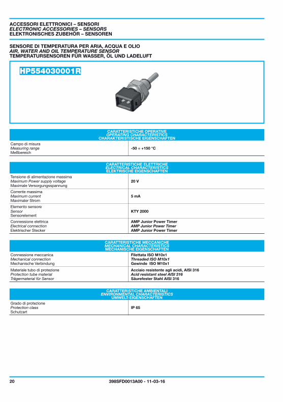
HP554030001R
-50 ÷ +150 °C
20 V
KTY 2000
5 mA
IP 65
TEMPERATURSENSOREN FÜR WASSER, ÖL UND LADELUFT
ELEKTRONISCHES ZUBEHÖR – SENSOREN
CHARAKTERISTISCHE EIGENSCHAFTEN
Meßbereich
ELEKTRISCHE EIGENSCHAFTEN
Maximale Versorgungsspannung
Maximaler Strom
Sensorelement
Elektrischer Stecker AMP Junior Power Timer
MECHANISCHE EIGENSCHAFTEN
Mechanische Verbindung Gewinde ISO M10x1
Trägermaterial für Sensor Säurefester Stahl AISI 316
UMWELT-EIGENSCHAFTEN
Schutzart
AIR, WATER AND OIL TEMPERATURE SENSOR
ELECTRONIC ACCESSORIES – SENSORS
OPERATING CHARACTERISTICS
Measuring range
ELECTRICAL CHARACTERISTICS
Maximum Power supply voltage
Maximum current
Sensor
Electrical connection AMP Junior Power Timer
MECHANICAL CHARACTERISTICS
Mechanical connection Threaded ISO M10x1
Protection tube material Acid resistant steel AISI 316
ENVIRONMENTAL CHARACTERISTICS
Protection class
SENSORE DI TEMPERATURA PER ARIA, ACQUA E OLIO
ACCESSORI ELETTRONICI – SENSORI
CARATTERISTICHE OPERATIVE
Campo di misura
CARATTERISTICHE ELETTRICHE
Tensione di alimentazione massima
Corrente massima
Elemento sensore
Connessione elettrica AMP Junior Power Timer
CARATTERISTICHE MECCANICHE
Connessione meccanica Filettata ISO M10x1
Materiale tubo di protezione Acciaio resistente agli acidi, AISI 316
CARATTERISTICHE AMBIENTALI
Grado di protezione
±0.2
±0.1
45°
9 12
±0.1
30
±0.1
Ø 3
.8
13.5
46.5±0.2
3
6
M10
x1b
a
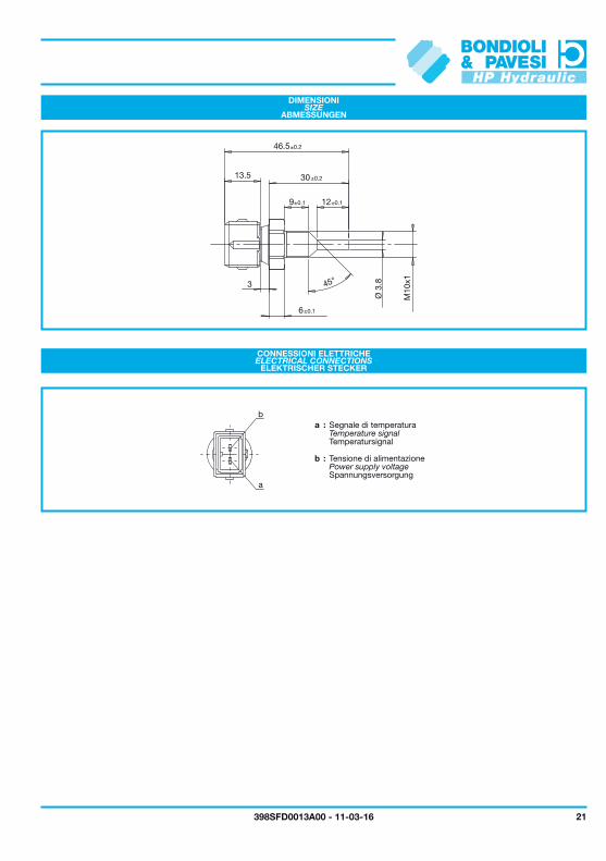
21398SFD0013A00 - 11-03-16
ABMESSUNGEN
ELEKTRISCHER STECKER
Spannungsversorgung
Temperatursignal
SIZE
ELECTRICAL CONNECTIONS
Power supply voltage
Temperature signal
DIMENSIONI
CONNESSIONI ELETTRICHE
a : Segnale di temperatura
b : Tensione di alimentazione
22 398SFD0013A00 - 11-03-16
CT0T1T2T3M0M1
D
G
S
Z
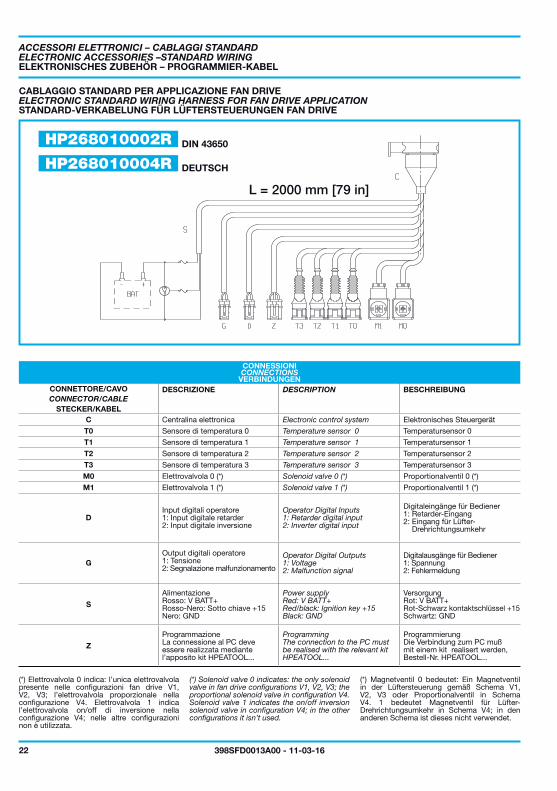
HP268010002R
HP268010004R
L = 2000 mm [79 in]
DIN 43650
DEUTSCH
ELEKTRONISCHES ZUBEHÖR – PROGRAMMIER-KABEL
STANDARD-VERKABELUNG FÜR LÜFTERSTEUERUNGEN FAN DRIVE
VERBINDUNGEN
(*) Magnetventil 0 bedeutet: Ein Magnetventil in der Lüftersteuerung gemäß Schema V1, V2, V3 oder Proportionalventil in Schema V4. 1 bedeutet Magnetventil für Lüfter-Drehrichtungsumkehr in Schema V4; in den anderen Schema ist dieses nicht verwendet.
BESCHREIBUNG
STECKER/KABELElektronisches Steuergerät
Temperatursensor 0
Temperatursensor 1
Temperatursensor 2
Temperatursensor 3
Proportionalventil 0 (*)
Proportionalventil 1 (*)
Digitaleingänge für Bediener 1: Retarder-Eingang 2: Eingang für Lüfter- Drehrichtungsumkehr
Digitalausgänge für Bediener 1: Spannung 2: Fehlermeldung
VersorgungRot: V BATT+Rot-Schwarz kontaktschlüssel +15Schwartz: GND
ProgrammierungDie Verbindung zum PC mußmit einem kit realisert werden,Bestell-Nr. HPEATOOL...
ELECTRONIC ACCESSORIES –STANDARD WIRING
ELECTRONIC STANDARD WIRING HARNESS FOR FAN DRIVE APPLICATION
CONNECTIONS
(*) Solenoid valve 0 indicates: the only solenoid valve in fan drive configurations V1, V2, V3; the proportional solenoid valve in configuration V4. Solenoid valve 1 indicates the on/off inversion solenoid valve in configuration V4; in the other configurations it isn’t used.
DESCRIPTIONCONNECTOR/CABLE
Electronic control system
Temperature sensor 0
Temperature sensor 1
Temperature sensor 2
Temperature sensor 3
Solenoid valve 0 (*)
Solenoid valve 1 (*)
Operator Digital Inputs1: Retarder digital input2: Inverter digital input
Operator Digital Outputs1: Voltage2: Malfunction signal
Power supplyRed: V BATT+Red/black: Ignition key +15Black: GND
ProgrammingThe connection to the PC must be realised with the relevant kitHPEATOOL...
(*) Elettrovalvola 0 indica: l’unica elettrovalvola presente nelle configurazioni fan drive V1, V2, V3; l’elettrovalvola proporzionale nella configurazione V4. Elettrovalvola 1 indica l’elettrovalvola on/off di inversione nella configurazione V4; nelle altre configurazioni non è utilizzata.
ACCESSORI ELETTRONICI – CABLAGGI STANDARD
CABLAGGIO STANDARD PER APPLICAZIONE FAN DRIVE
CONNESSIONI
CONNETTORE/CAVO DESCRIZIONE
Centralina elettronica
Sensore di temperatura 0
Sensore di temperatura 1
Sensore di temperatura 2
Sensore di temperatura 3
Elettrovalvola 0 (*)
Elettrovalvola 1 (*)
Input digitali operatore1: Input digitale retarder2: Input digitale inversione
Output digitali operatore1: Tensione2: Segnalazione malfunzionamento
AlimentazioneRosso: V BATT+Rosso-Nero: Sotto chiave +15Nero: GND
ProgrammazioneLa connessione al PC deve essere realizzata mediante l’apposito kit HPEATOOL...