Sistemi di attivazione Activation Systems EasyService ... · A. EasyService 230Vac: scatola di...
76
Sistemi di attivazione Activation Systems EasyService - MultiService Manuale Operativo Operating Manual
Transcript of Sistemi di attivazione Activation Systems EasyService ... · A. EasyService 230Vac: scatola di...
Sistemi di attivazione Activation Systems
EasyService - MultiService
Manuale Operativo Operating Manual
alfred
A.u.S.Spielgeräte GmbH
www.aus.at EasyService- Multiservice-I Rev. 01 16/05/2006
Pag. 2 di 76
Sommario - Index 1 Introduzione .........................................................................................................................5
1.1 Descrizione generale ...................................................................................................................... 5 2 Avvertenze............................................................................................................................5 3 Dichiarazione di conformità ................................................................................................6 4 Garanzia................................................................................................................................8 5 Note generali ........................................................................................................................8
5.1 Controlli al ricevimento della spedizione......................................................................................... 8 5.2 Tipologia di imballo ......................................................................................................................... 8 5.3 Identificazione apparecchiatura ...................................................................................................... 9
6 Caratteristiche dell’apparecchiatura ..................................................................................9 6.1 Dati tecnici .................................................................................................................................... 10 6.2 Ingombri ........................................................................................................................................ 10
7 Rischi derivanti dall’uso dell’apparecchiatura ................................................................10 7.1 Rischi durante la manutenzione dell’apparecchiatura .................................................................. 12 7.2 Sicurezze ...................................................................................................................................... 12 7.3 Segnaletica ................................................................................................................................... 12
8 Movimentazione e posizionamento ..................................................................................14 9 Installazione .......................................................................................................................14
9.1 Apparecchiature con alimentazione da rete 230 Vac ................................................................... 14 9.2 Apparecchiature con alimentazione 24 Vac/dc............................................................................. 16 9.3 Collegamento delle uscite servizio................................................................................................ 17 9.4 Messa in servizio .......................................................................................................................... 18 9.5 Istruzioni di montaggio delle periferiche........................................................................................ 19
10 Funzionamento e programmazione..................................................................................22 10.1 CON GETTONIERA MECCANICA............................................................................................... 22 10.2 Funzionamento normale ............................................................................................................... 22 10.3 Procedura generale di impostazioni parametri ............................................................................. 23 10.4 Programmazione durata del servizio ............................................................................................ 24 10.5 Settaggio del tempo...................................................................................................................... 24 10.6 Settaggio tempo di preavviso ....................................................................................................... 25 10.7 Settaggio numero Monete/Gettoni ................................................................................................25 10.8 Settaggio modo di lavoro NA / NC................................................................................................ 25 10.9 Abilitazione pulsante Start/Stop.................................................................................................... 25 10.10 Contabilità ............................................................................................................................. 25
Gentile cliente, la ringraziamo per la fiducia accordataci con l’acquisto di un nostro prodotto. Se Lei avrà la costanza di seguire attentamente le indicazioni contenute nel presente manuale, siamo certi che potrà apprezzarne nel tempo e con soddisfazione la qualità. La preghiamo di leggere attentamente le indicazioni contenute nel manuale che riguardano l’uso corretto del nostro prodotto, in conformità alle prescrizioni essenziali di sicurezza.
Dear Customer, Thank you for buying one of our products. If you carefully follow the indications included in this manual, we are sure you will appreciate our quality over time with full satisfaction. We kindly ask you to carefully read the instructions of this manual about the correct use of our product in accordance with the basic safety provisions.
alfred
A.u.S.Spielgeräte GmbH

www.aus.at EasyService- Multiservice-I Rev. 01 16/05/2006
Pag. 3 di 76
11 Schema di collegamento ...................................................................................................26 12 Funzionamento e programmazione..................................................................................27
12.1 CON GETTONIERA ELETTRONICA ........................................................................................... 27 12.2 Caratteristiche generali ................................................................................................................. 27 12.3 Funzionamento normale Timer progressivo ................................................................................. 27
12.3.1 Programmazione in locale per la modalità Timer progressivo ......................................................28 12.4 Funzionamento normale Timer progressivo con richiesta del servizio ......................................... 28
12.4.1 Programmazione locale per la modalità Timer progressivo con richiesta del servizio ..............28 12.5 Funzionamento normale Doppio timer progressivo ...................................................................... 28 12.6 Programmazione locale per la modalità Doppio timer progressivo............................................... 30 12.7 Programmazione con Clone 5 ...................................................................................................... 31 12.8 Contabilità..................................................................................................................................... 31
13 Strumenti e accessori (solo per le versioni con gettoniera RM5T)................................31 14 Schema di collegamento ...................................................................................................32 15 Funzionamento e programmazione..................................................................................32
15.1 CON SISTEMA CHIAVE E GETTONIERA ELETTRONICA......................................................... 32 15.2 FUNZIONAMENTO NORMALE.................................................................................................... 33 15.3 PROGRAMMAZIONE E CONFIGURAZIONE DEL SISTEMA ..................................................... 33 15.4 PROGRAMMAZIONE LOCALE DELLA GETTONIERA............................................................... 34 15.5 TARATORE PORTATILE PER GETTONIERA (OPZIONALE)..................................................... 35 15.6 CONTABILITA’ ............................................................................................................................. 35 15.7 STRUMENTI E ACCESSORI ....................................................................................................... 36
16 SCHEMA ELETTRICO ........................................................................................................37 17 Manutenzione e inattività ..................................................................................................37 18 Ricambi ...............................................................................................................................39 19 Smaltimento del prodotto..................................................................................................40
20 Introduction ........................................................................................................................41
20.1 General Description ...................................................................................................................... 41 21 Warnings.............................................................................................................................41 22 Declaration of conformity..................................................................................................42 23 Guarantee ...........................................................................................................................44 24 General notes .....................................................................................................................44
24.1 Checks upon the receipt of products ............................................................................................44 24.2 Type of packaging ........................................................................................................................ 44 24.3 Device identification...................................................................................................................... 45
25 Characteristics of the device ............................................................................................45 25.1 Overall dimensions ....................................................................................................................... 46
26 Risks deriving from using the device...............................................................................46 26.1 Possible risks during the device maintenance.............................................................................. 48 26.2 Safety............................................................................................................................................ 48 26.3 Signals .......................................................................................................................................... 48
27 Handling and positioning ..................................................................................................50 28 Installation ..........................................................................................................................50
28.1 Devices with 230 Vac mains power supply.................................................................................. 50 28.2 Devices with 24 Vac/dc power supply .......................................................................................... 52 28.3 Connecting the service outputs..................................................................................................... 53 28.4 Start up ......................................................................................................................................... 54 28.5 Assembly instructions for peripheral devices................................................................................ 55 28.6 Connect all the wirings to the relevant connectors, see figures 31, 32 and 33............................. 57 28.7 Apply the coin mechanism to the pivoting support (fig.34). .......................................................... 58
alfred
A.u.S.Spielgeräte GmbH

www.aus.at EasyService- Multiservice-I Rev. 01 16/05/2006
Pag. 4 di 76
28.8 Re-install the pivoting support and fix it using the relevant screws verifying that the display is centered in the door window (fig.28). .................................................................................................... 58
29 Operation and programming.............................................................................................59 29.1 Operation and programming with MECHANICAL COIN MECHANISM ........................................ 59
29.1.1 General procedure for parameter setting..............................................................................................59 29.1.2 Service time programming ....................................................................................................................60 29.1.3 Notice time setting.................................................................................................................................61 29.1.4 Setting coin/token number ....................................................................................................................61 29.1.5 NA / NC operating mode setting ...........................................................................................................61 29.1.6 Enabling Start/Stop button ....................................................................................................................61 29.1.7 Accounting ............................................................................................................................................62 29.1.8 Wiring diagram......................................................................................................................................62
29.2 Operation and programming with ELECTRONIC COIN MECHANISM ........................................ 63 29.2.1 General characteristics .........................................................................................................................63 29.2.2 Regular operation with Progressive Timer............................................................................................63 29.2.3 Regular operation of the progressive Timer with service request ........................................................64 29.2.4 Double progressive timer normal working.............................................................................................65 29.2.5 Programming with Clone 5....................................................................................................................67 29.2.6 Accounting ............................................................................................................................................68 29.2.7 Tools and accessories (only for models with RM5Tcoin mechanism)..................................................68 29.2.8 RM5T input wiring, RM5T-500 code .....................................................................................................68 29.2.9 Wiring diagram......................................................................................................................................68
29.3 Operation and programming with KEY SYSTEM and ELECTRONIC COIN MECHANISM ......... 69 29.3.1 Normal operation...................................................................................................................................69 29.3.2 System programming and configuration ...............................................................................................70 29.3.3 Local programming of the coin mechanism ..........................................................................................71 29.3.4 Accounting ............................................................................................................................................71 29.3.5 Tools and accessories ..........................................................................................................................72 29.3.6 Wiring diagram......................................................................................................................................73
30 Maintenance and inactivity ...............................................................................................74 31 Spare parts .........................................................................................................................75 32 Product disposal ................................................................................................................76
alfred
A.u.S.Spielgeräte GmbH

www.aus.at EasyService- Multiservice-I Rev. 01 16/05/2006
Pag. 5 di 76
1 Introduzione Il presente manuale e gli allegati annessi forniscono tutte le informazioni necessarie all'installazione, alle parti costituenti il prodotto, l'uso e il funzionamento, nonché un'introduzione tecnica per una buona manutenzione ed un appropriato uso del prodotto stesso. Le informazioni contenute nel presente manuale sono soggette a modifiche senza preavviso e non rappresentano un impegno da parte di A.u.S. Spielgeraete GmbHOgni cura è stata posta nella raccolta e nella verifica della documentazione contenuta in questo manuale; tuttavia A.u.S. Spielgeraete non può assumersi alcuna responsabilità derivante dall'utilizzo dello stesso. Lo stesso dicasi per ogni persona o società coinvolta nella creazione e nella produzione di questo manuale. Salvodiversa specificazione, ogni riferimento a società, nomi, dati ed indirizzi utilizzati negli esempi è puramente casuale ed ha il solo scopo di illustrare l'uso del prodotto A.u.S. Spielgeraete GmbH. Si fa esplicito divieto di riprodurre qualsiasi parte di questo documento, in qualsiasi forma, senza l'esplicito permesso di A.u.S. Spielgeraete GmbH.
1.1 Descrizione generale I box di comando EasyService e MultiService sono la soluzione ottimale per automatizzare dall’esterno il pagamento e l’attivazione di qualsiasi servizio a tempo; si differenziano in vari modelli in grado di pilotare fino a 6 servizi distinti. Sono particolarmente adatte per automatizzare apparecchiature manuali preesistenti e per essere collocate in ambienti esterni. Sono infatti impermeabili all’acqua e particolarmente robuste,il grado di protezione dell’apparecchio, alla data di edizione del seguente manuale, è pari a “IP35” solo se applicata come da prescrizioni, per resistere agli agenti atmosferici e agli atti vandalici. I modelli si differenziano per tipologia di configurazione e sono di seguito riportati:
A. EasyService 230Vac: scatola di comando con gettoniera meccanica monoservizio. B. EasyService 24Vac/dc: scatola di comando con gettoniera meccanica monoservizio. C. MultiService 2 Prezzi 230Vac: scatola di comando con gettoniera elettronica gestisce fino a due servizi. D. MultiService 2 Prezzi 24Vac/dc: scatola di comando con gettoniera elettronica gestisce fino a due servizi. E. MultiService 6 Prezzi 230Vac: scatola di comando con gettoniera elettronica gestisce fino a sei servizi. F. MultiService 6 Prezzi 24Vac/dc: scatola di comando con gettoniera elettronica gestisce fino a sei servizi.
2 Avvertenze Leggere attentamente questo manuale prima dell’installazione. La conoscenza delle informazioni e delle prescrizioni contenute nel presente manuale è essenziale per un corretto uso del prodotto. Verificare al momento del ricevimento che la confezione ed il prodotto stesso non abbiano subito danni durante il trasporto. Porre attenzione alle connessioni elettriche. I guasti causati dal mancato rispetto di tutte le avvertenze riportate in questa pubblicazione, non sono coperte da garanzia. Nel presente documento sono utilizzate simbologie per evidenziare situazioni importanti che devono essere attentamente osservate.
ATTENZIONE!
AVVERTENZE IMPORTANTI
LEGGERE attentamente questo manuale prima della messa in funzione
alfred
A.u.S.Spielgeräte GmbH

www.aus.at EasyService- Multiservice-I Rev. 01 16/05/2006
Pag. 6 di 76
3 Dichiarazione di conformità
DICHIARAZIONE CE DI CONFORMITA’
No.: 30-1029 Il sottoscritto, rappresentante il seguente costruttore
Costruttore:
Indirizzo: o rappresentante il mandatario autorizzato dal costruttore all’interno della Comunità (o dell’Area Economica Europea) indicato qui di seguito (se applicabile)
Rappresentante autorizzato:
Indirizzo: dichiara qui di seguito che il prodotto
Identificazione del prodotto: Scatola di comando Easy/Multi Service Risulta in conformità a quanto previsto dalle seguenti direttive comunitarie:
Riferimento n° Titolo
98/37/CE Nuova direttiva macchine
e che sono state applicate tutte le norme e/o specifiche tecniche sotto indicate. Ultime due cifre dell’anno in cui è stata affissa la marcatura CE 05 Gessate, / / _____________________
(firma) (nome e funzione della persona incaricata di firmare per conto del costruttore o suo rappresentante autorizzato)
alfred
A.u.S.Spielgeräte GmbH
www.aus.at EasyService- Multiservice-I Rev. 01 16/05/2006
Pag. 7 di 76
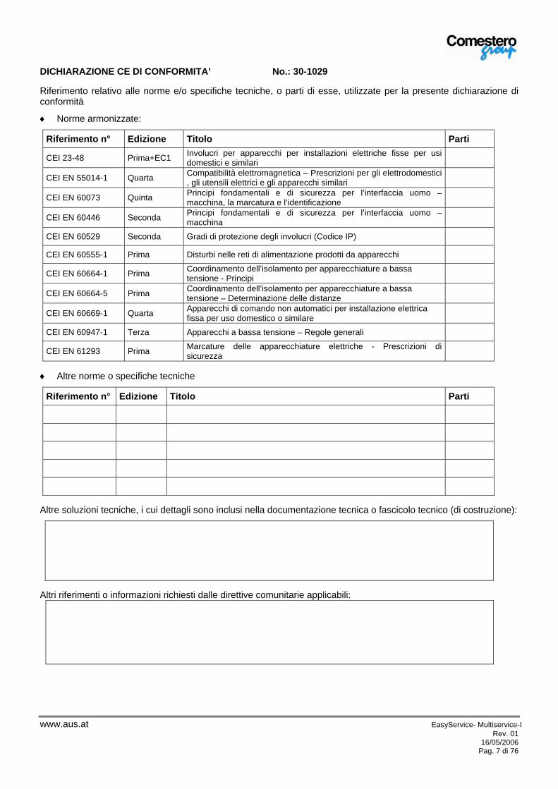
DICHIARAZIONE CE DI CONFORMITA’ No.: 30-1029 Riferimento relativo alle norme e/o specifiche tecniche, o parti di esse, utilizzate per la presente dichiarazione di conformità
♦ Norme armonizzate:
Riferimento n° Edizione Titolo Parti
CEI 23-48 Prima+EC1 Involucri per apparecchi per installazioni elettriche fisse per usi domestici e similari
CEI EN 55014-1 Quarta Compatibilità elettromagnetica – Prescrizioni per gli elettrodomestici , gli utensili elettrici e gli apparecchi similari
CEI EN 60073 Quinta Principi fondamentali e di sicurezza per l’interfaccia uomo – macchina, la marcatura e l’identificazione
CEI EN 60446 Seconda Principi fondamentali e di sicurezza per l’interfaccia uomo – macchina
CEI EN 60529 Seconda Gradi di protezione degli involucri (Codice IP)
CEI EN 60555-1 Prima Disturbi nelle reti di alimentazione prodotti da apparecchi
CEI EN 60664-1 Prima Coordinamento dell’isolamento per apparecchiature a bassa tensione - Principi
CEI EN 60664-5 Prima Coordinamento dell’isolamento per apparecchiature a bassa tensione – Determinazione delle distanze
CEI EN 60669-1 Quarta Apparecchi di comando non automatici per installazione elettrica fissa per uso domestico o similare
CEI EN 60947-1 Terza Apparecchi a bassa tensione – Regole generali
CEI EN 61293 Prima Marcature delle apparecchiature elettriche - Prescrizioni di sicurezza
♦ Altre norme o specifiche tecniche
Riferimento n° Edizione Titolo Parti
Altre soluzioni tecniche, i cui dettagli sono inclusi nella documentazione tecnica o fascicolo tecnico (di costruzione):
Altri riferimenti o informazioni richiesti dalle direttive comunitarie applicabili:
alfred
A.u.S.Spielgeräte GmbH

www.aus.at EasyService- Multiservice-I Rev. 01 16/05/2006
Pag. 8 di 76
4 Garanzia I nostri prodotti vengono garantiti per un periodo di 12 mesi. Fa fede il numero di matricola presente sull’etichetta. La garanzia decade qualora l’acquirente sia inadempiente nel pagamento del prezzo. La garanzia non si applica nei seguenti casi:
• manomissione dell’etichetta riportante il numero di matricola dell’apparecchio; • avaria o rottura causata dal trasporto; • avaria o rottura derivante da atti vandalici, calamità naturali o di origine dolosa; • errata o cattiva installazione del prodotto; • inadeguatezza o anomalia degli impianti elettrici; • trascuratezza, negligenza o incapacità nell’uso del prodotto; • mancata osservanza delle istruzioni per il funzionamento; • interventi per vizi presunti o per verifiche di comodo; • intervento non autorizzato sul prodotto.
Gli interventi di riparazione avvengono presso il nostro laboratorio di Vienna (il trasporto è da considerarsi a carico del mittente). E’ esclusa la possibilità che A.u.S.Spielgeraete GmbH presti assistenza di qualsiasi natura presso il cliente se non su preventivo accordo. Si fa comunque esplicito riferimento alle condizioni generali di vendita, consultabili sul sito www.aus.at o disponibili su richiesta. Per ogni reso in conto riparazione dovrà essere allegata una chiara descrizione del difetto riscontrato; la restituzione dello stesso avverrà in porto assegnato o porto franco c/addebito. Anche al termine della garanzia il nostro servizio di Post Vendita rimarrà comunque a disposizione per consulti telefonici.
5 Note generali
5.1 Controlli al ricevimento della spedizione All’atto del ricevimento del prodotto occorre controllare che lo stesso non abbia subito danni durante il trasporto. Se si dovessero notare danni di qualsiasi natura si faccia immediatamente reclamo al trasportatore. Alla fine del trasporto l’imballo deve risultare integro, vale a dire non deve:
• Presentare ammaccature, segni di urti, deformazioni o rotture nell’involucro contenitore. • Presentare zone bagnate o segni che possano portare a supporre che l’involucro sia stato esposto alla
pioggia, al gelo o al calore. • Presentare segni di manomissione.
Verificare che il contenuto della confezione corrisponda all’ordine.
5.2 Tipologia di imballo L’apparecchiatura viene consegnata collaudata ed attrezzata nel seguente modo: - Sportello chiuso - Sacchetto trasparente, posizionato sul lato superiore del BOX, con due copie della chiave della macchina - Cassetta porta moneta - Display tropicalizzato - Sistema chiave EuroKey tropicalizzato - Sacchetto trasparente con connettori ad innesto femmina tipo FASTON (4,8x0,8mm) L’apparecchiatura viene spedita all’interno di una scatola con dimensioni esterne di (H 36 x L 26 x P 24,5 cm). Seguire le istruzioni riportate sul lato dell’imballo.
alfred
A.u.S.Spielgeräte GmbH

www.aus.at EasyService- Multiservice-I Rev. 01 16/05/2006
Pag. 9 di 76
5.3 Identificazione apparecchiatura La targa riportata in figura 1, riporta le caratteristiche principali di funzionamento e di identificazione dell’apparecchiatura. Particolarmente importante è il numero di matricola stampigliato nel relativo riquadro 1. Tale numero va sempre citato in ogni richiesta di assistenza, ricambi, riparazioni o informazioni relative al funzionamento dell’apparecchiatura.
Figura 1
Figura 2
6 Caratteristiche dell’apparecchiatura Scatola comando per l’attivazione di servizi esterni. Il numero dei servizi attuabili dipende dalla versione del prodotto. La versione con gettoniera meccanica prevede un solo servizio, quella con gettoniera elettronica RM5T può abilitare fino a due uscite e quella con sistema chiave, a transponder, “EUROKEY”può pilotare 6 differenti servizi. I contatti verso l’esterno sono di tipo a Relè, le specifiche sono riportate nel paragrafo 8.3
La targa d’identificazione macchina deve essere ben leggibile. E’ vietato asportarla o manomettere i dati riportati. In caso di danneggiamento o smarrimento, richiedere al costruttore una nuova targa sostitutiva. La targa è montata sull’apparecchiatura come indicato in figura 2.
alfred
A.u.S.Spielgeräte GmbH
alfred
Rechteck
alfred
A.u.S.Spielgeräte GmbH

www.aus.at EasyService- Multiservice-I Rev. 01 16/05/2006
Pag. 10 di 76
6.1 Dati tecnici
6.2 Ingombri
7 Rischi derivanti dall’uso dell’apparecchiatura E’ buona norma verificare l’apparecchiatura, quando è aperta, solo se priva di alimentazione. Aprire la parte basculante (fig.22 e 23) solo se l’alimentazione è stata, preventivamente, tolta direttamente dall’interruttore differenziale dell’impianto. Tutte le parti mobili, sportello corpo basculante e scatola porta monete, possono causare delle lesioni di varia entità, se non opportunamente manovrate. Rischi dovuti all’energia elettrica: contatti diretti durante l’allacciamento alla linea di alimentazione generale vedi norma “EN 61140” -Protezione contro i contatti elettrici aspetti comuni degli impianti-. Rischi dovuti all’energia elettrica: per la corretta installazione dell’apparecchio verificare che l’impianto risponda alle prescrizioni di sicurezza riportate nella norma “CEI 64-8/7” –Impianti elettrici utilizzatori… AMBIENTI ed APPLICAZIONI PARTICOLARI-. A titolo di esempio:
EASY SERVICE MULTISERVICE 2 PREZZI MULTISERVICE 6 PREZZIVersione da
rete Bassa tensione Versione da rete Bassa tensione Versione da
rete Bassa tensione TENSIONE INGRESSO
230 Vac ± 10%
18÷28 Vdc ± 10%
oppure 12÷18 Vac ±
10%
230 Vac ± 10%
12÷24 Vdc ± 10%
oppure 12÷24 Vac ±
10%
230 Vac ± 10%
18÷34 Vdc ± 10% oppure
12÷24 Vac ± 10%
POTENZA ASSORBITA 2W 16 W 40 W
USCITE A relay, portata in corrente 3A a 230Vac
A relay, portata in corrente 2A a 30Vdc o 0,5A a 125Vac
A relay, portata in corrente 4A a 230Vac
DIMENSIONI (173 X 331,5 X 164,25) mm
PESO 8,5 Kg (con cassetta vuota)
CAPACITA’ MONETE 400 circa (monete da 0,50€ o 1,00 €uro)
PERIFERICHE INSTALLATE
Gettoniera meccanica (Opzionale) Gettoniera elettronica RM5T (Opzionale)
Gettoniera elettronica RM5 (Opzionale)
alfred
A.u.S.Spielgeräte GmbH

www.aus.at EasyService- Multiservice-I Rev. 01 16/05/2006
Pag. 11 di 76
Nell’applicazione tipo “Docce da Campeggio” l’installazione del Box Easy/Multi Service può essere effettuata nella Zona 3, nei casi in cui l’alimentazione avvenga con tensione di 230 Vac, e nella Zona 2 nei casi in cui l’alimentazione è 24 Vac/dc (vedi nota sotto), con tutte le precauzioni e limitazioni segnalate nella norma “CEI 64-8/7” –Impianti elettrici utilizzatori… AMBIENTI ed APPLICAZIONI PARTICOLARI-. Nota:
• viene definita zona 2 “volume delimitato dalla superficie verticale della Zona 1;dalla superficie verticale situata a 0,60 m dalla superficie precedente e parallela ad essa; dal piano; e dal piano situato a 2,25 m sopra il pavimento.
• viene definita Zona 3 “volume delimitato dalla superficie verticale esterna della Zona 2; dalla superficie precedente e parallela ad essa; dal pavimento; e dal piano situato a 2,25 m sopra il pavimento”
Il disegno riporta l’esempio di una doccia con due pareti fisse e piatto, per tutte le altre versioni si deve far riferimento alla : NORMA TECNICA CEI 64-8/7:2004-06 fig. 701A o fig. 701B .
Operazioni a cura del tecnico qualificato. Precauzioni:
• Effettuare il collegamento all’impianto di messa a terra, prima dei collegamenti dell’apparecchiatura o degli aggregati vedi figura 3, per la versione EasyService, e figura 4, per le versioni MultiService.
• Verificare che l’impianto elettrico si opportunamente dimensionato, in relazione all’assorbimento dell’Apparecchio e conforme alle norme che riguardano il campo di aplicazione
• Verificare che la linea di distribuzione sia dimensionata in relazione all’intensità di corrente assorbita dall’apparecchiatura.
• Installare a monte dell’apparecchiatura un interruttore magnetotermico differenziale adeguato alle prestazioni della apparecchio scelto.
alfred
A.u.S.Spielgeräte GmbH

www.aus.at EasyService- Multiservice-I Rev. 01 16/05/2006
Pag. 12 di 76
Figura 3
Figura 4
7.1 Rischi durante la manutenzione dell’apparecchiatura Rischi dovuti all’energia elettrica: rischi di contatto diretto con parti in tensione all’interno dell’armadio contenente i componenti elettrici.
Operazioni a cura del tecnico qualificato. Precauzioni: Prestare assistenza sulla macchina solo dopo essersi accertati di aver disinserito l’interruttore generale.
7.2 Sicurezze L’apparecchiatura è stata realizzata secondo i principi di sicurezza previsti dalla “Direttiva macchine” 98/37/CE: Direttiva del Parlamento europeo e del Consiglio del 22 giugno 1998 concernente il ravvicinamento delle legislazioni degli Stati membri relative alle macchine.
7.3 Segnaletica L’apparecchiatura è stata corredata di segnaletica composta da etichette di avvertenza posizionate in prossimità delle zone pericolose e riportano i pittogrammi di indicazione pericolo convenzionali con simbologie e/o scritte di riferimento (Fig. 5 e Fig. 6).
Figura 5
Simbolo di tensione: è posto nelle vicinanze dei punti del circuito elettrico della scatola di comando in cui circola tensione, applicata solo sugli apparecchi alimentati a 230 Vac.
ATTENZIONE! : Pericolo di folgorazione
alfred
A.u.S.Spielgeräte GmbH
www.aus.at EasyService- Multiservice-I Rev. 01 16/05/2006
Pag. 13 di 76
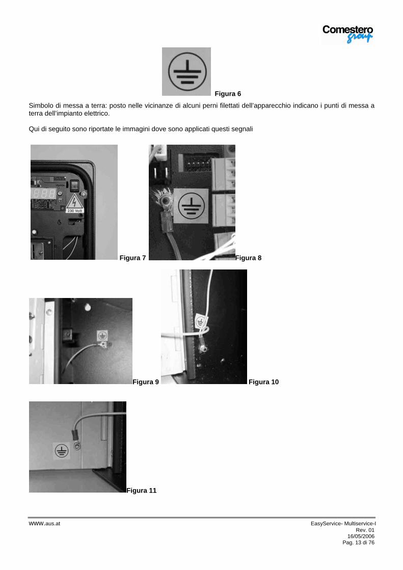
Figura 6
Simbolo di messa a terra: posto nelle vicinanze di alcuni perni filettati dell’apparecchio indicano i punti di messa a terra dell’impianto elettrico. Qui di seguito sono riportate le immagini dove sono applicati questi segnali
Figura 7 Figura 8
Figura 9 Figura 10
Figura 11
alfred
A.u.S.Spielgeräte GmbH

www.aus.at EasyService- Multiservice-I Rev. 01 16/05/2006
Pag. 14 di 76
8 Movimentazione e posizionamento Il peso dell’apparecchio fa si che sia sufficientemente agevole il trasporto senza l’ausilio di mezzi meccanici di varia natura. Si consiglia, comunque, di prestare la MASSIMA ATTENZIONE durante il trasporto, onde evitare che la macchina possa cadere e danneggiarsi.
9 Installazione Per l’installazione a parete della macchina: Vedere la figura foratura 12 . Utilizzare viti di diametro massimo 4 mm. Verificare che la parete di applicazione sia libera da protuberanze.
Figura 12
9.1 Apparecchiature con alimentazione da rete 230 Vac Per il collegamento elettrico: Installare, a monte dell’apparecchiatura, un interruttore magnetotermico differenziale adeguato alle prestazioni della apparecchio scelto, avente corrente differenziale nominale non superiore a 30 mA. Il box Easy/Multi Service risponde a tutte le prescrizioni della norma “CEI EN 60529 Gradi di protezione degli involucri” che riguardano il grado di protezione IP35, per cui viene dichiarata la conformità. L’apparecchio deve essere installato a “MURO” per ottenere il grado di protezione sopra citato. Per non modificare il grado di protezione dell’apparecchio le guarnizioni, all’interno della porta e sulla parte posteriore, non devono essere rimosse. Per il passaggio dei cavi di alimentazione e di comando è necessario rimettere, alla fine dell’operazione di installazione, la guarnizione posteriore nella posizione originaria. Tutti i collegamenti elettrici della macchina sono installati ad eccezione dell’alimentazione e dell’accettatore di monete e/o gettoni. Per quest’ultimo fare riferimento al punto 9.5 . Il cliente deve farsi carico dell’allacciamento della linea elettrica ed eseguire un impianto secondo le relative norme, “CEI 64-8/7” “Impianti elettrici utilizzatori a tensione nominale non superiore a 1000V in c.a. “Ambienti e applicazioni particolari”. Portare, sul retro della macchina, il cavo di alimentazione, Fase Neutro e Terra. All’interno dell’imballo c’è una confezione con tre connettori ad innesto femmina tipo FASTON due da 4,8mm ed uno da 6,3mm per la Terra.
alfred
A.u.S.Spielgeräte GmbH

www.aus.at EasyService- Multiservice-I Rev. 01 16/05/2006
Pag. 15 di 76
Negli apparecchi tipo Easy Service in sostituzione del FASTON da 6,3mm è presente un terminale a puntale isolato. Nelle immagini 12, 13, 14, 15 e 16 viene evidenziato il modo corretto per intestare i connettori e collegarli alla macchina.
Figura 13
Innestare i FASTON sui cavi di alimentazione (4,8x0,8mm) e il cavo di Massa (6,3x0,8mm) con l’opportuna pinza.
Figura 14
Collegare il FASTON di massa sul Filtro rete dell’apparecchio, solo per versione Multi Service. Collegare il puntale di Massa sulla scheda elettronica, solo per Easy Service.
Figura 15
Collegare i la “Fase” e il “Neutro” nell’interruttore bipolare come in figura 16.
Figura 16
alfred
A.u.S.Spielgeräte GmbH

www.aus.at EasyService- Multiservice-I Rev. 01 16/05/2006
Pag. 16 di 76
Figura 17
9.2 Apparecchiature con alimentazione 24 Vac/dc Per il collegamento elettrico: Installare, a monte dell’apparecchiatura, un interruttore magnetotermico differenziale adeguato alle prestazioni della apparecchio scelto, avente corrente differenziale nominale non superiore a 30 mA. Il box Easy/Multi Service risponde a tutte le prescrizioni della norma “CEI EN 60529 Gradi di protezione degli involucri” che riguardano il grado di protezione IP35, per cui viene dichiarata la conformità. L’apparecchio deve essere installato a “MURO” per ottenere il grado di protezione sopra citato. Tutti i collegamenti elettrici della macchina sono installati ad eccezione dell’alimentazione, vedi paragrafo precedente, e dell’accettatore di monete e/o gettoni. Per quest’ultimo fare riferimento al punto 9.5 . Il cliente deve farsi carico dell’allacciamento della linea elettrica. Portare, sul retro della macchina, il cavo di alimentazione, 24Vac/dc e Terra. All’interno dell’imballo c’è una confezione con tre connettori ad innesto femmina tipo FASTON due da 4,8mm ed uno da 6,3mm per la Terra. Negli apparecchi tipo Easy Service, in sostituzione del FASTON da 6,3mm, è presente un terminale a puntale isolato. Nelle immagini 12, 13, 14, 15 e 16 viene evidenziato il modo corretto per intestare i connettori e collegarli alla macchina.
Installare a monte dell’apparecchiatura un interruttore magnetotermico differenziale adeguato alle prestazioni della apparecchio scelto.
alfred
A.u.S.Spielgeräte GmbH
www.aus.at EasyService- Multiservice-I Rev. 01 16/05/2006
Pag. 17 di 76
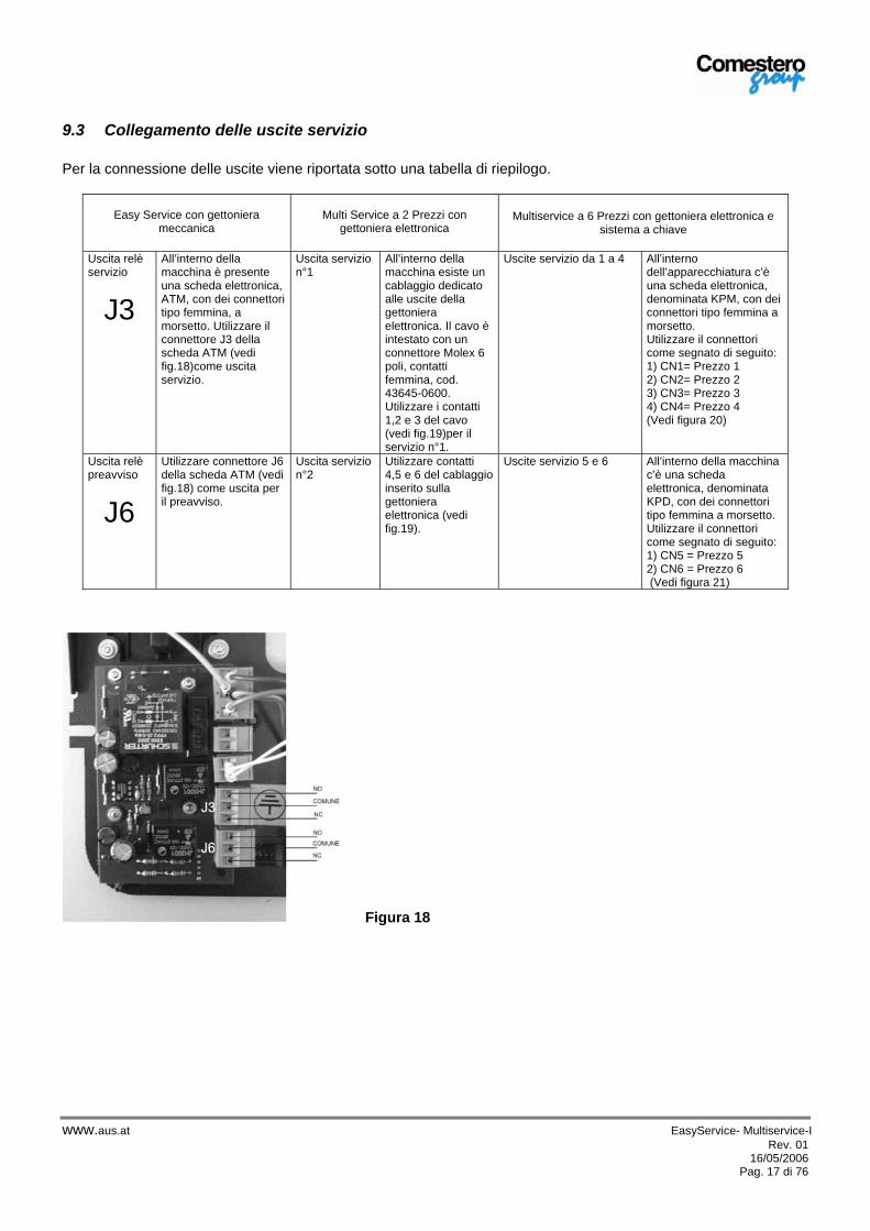
9.3 Collegamento delle uscite servizio Per la connessione delle uscite viene riportata sotto una tabella di riepilogo.
Easy Service con gettoniera
meccanica
Multi Service a 2 Prezzi con
gettoniera elettronica Multiservice a 6 Prezzi con gettoniera elettronica e
sistema a chiave
Uscita relè servizio
J3
All’interno della macchina è presente una scheda elettronica, ATM, con dei connettori tipo femmina, a morsetto. Utilizzare il connettore J3 della scheda ATM (vedi fig.18)come uscita servizio.
Uscita servizio n°1
All’interno della macchina esiste un cablaggio dedicato alle uscite della gettoniera elettronica. Il cavo è intestato con un connettore Molex 6 poli, contatti femmina, cod. 43645-0600. Utilizzare i contatti 1,2 e 3 del cavo (vedi fig.19)per il servizio n°1.
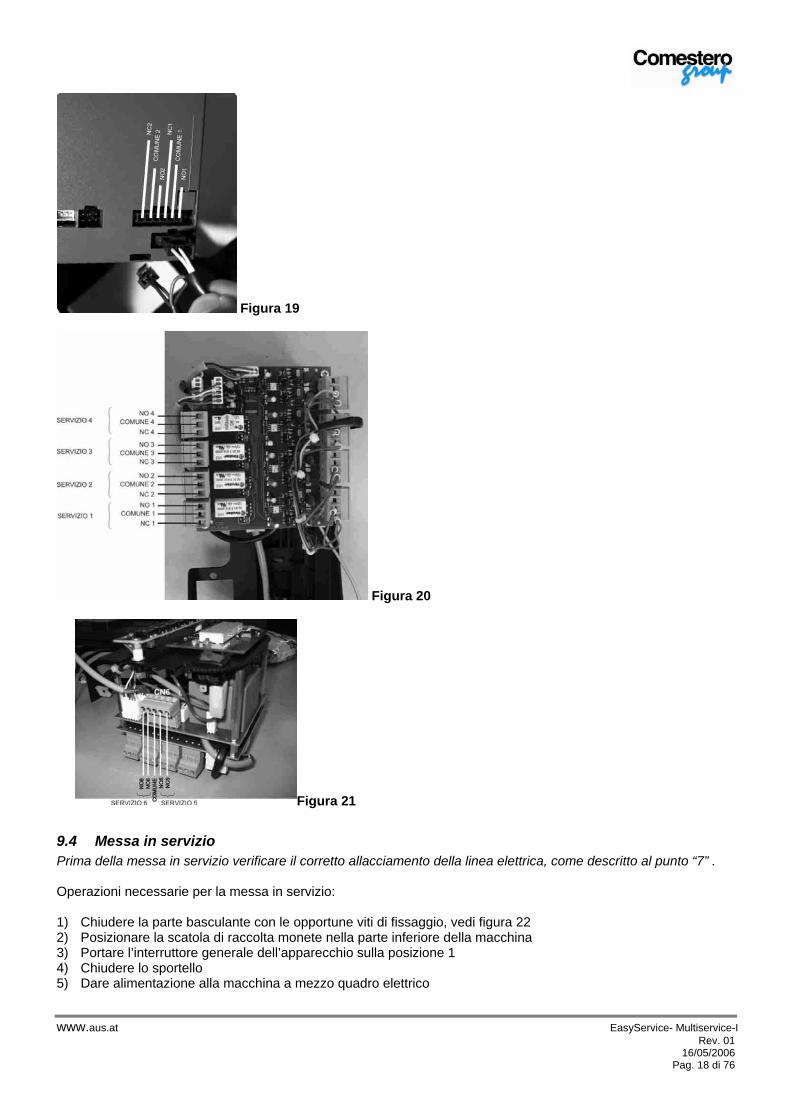
Uscite servizio da 1 a 4 All’interno dell’apparecchiatura c’è una scheda elettronica, denominata KPM, con dei connettori tipo femmina a morsetto. Utilizzare il connettori come segnato di seguito: 1) CN1= Prezzo 1 2) CN2= Prezzo 2 3) CN3= Prezzo 3 4) CN4= Prezzo 4 (Vedi figura 20)
Uscita relè preavviso
J6
Utilizzare connettore J6 della scheda ATM (vedi fig.18) come uscita per il preavviso.
Uscita servizio n°2
Utilizzare contatti 4,5 e 6 del cablaggio inserito sulla gettoniera elettronica (vedi fig.19).
Uscite servizio 5 e 6 All’interno della macchina c’è una scheda elettronica, denominata KPD, con dei connettori tipo femmina a morsetto. Utilizzare il connettori come segnato di seguito: 1) CN5 = Prezzo 5 2) CN6 = Prezzo 6 (Vedi figura 21)
Figura 18
alfred
A.u.S.Spielgeräte GmbH
www.aus.at EasyService- Multiservice-I Rev. 01 16/05/2006
Pag. 18 di 76
Figura 19
Figura 20
Figura 21
9.4 Messa in servizio Prima della messa in servizio verificare il corretto allacciamento della linea elettrica, come descritto al punto “7” . Operazioni necessarie per la messa in servizio: 1) Chiudere la parte basculante con le opportune viti di fissaggio, vedi figura 22 2) Posizionare la scatola di raccolta monete nella parte inferiore della macchina 3) Portare l’interruttore generale dell’apparecchio sulla posizione 1 4) Chiudere lo sportello 5) Dare alimentazione alla macchina a mezzo quadro elettrico
www.aus.at EasyService- Multiservice-I Rev. 01 16/05/2006
Pag. 19 di 76
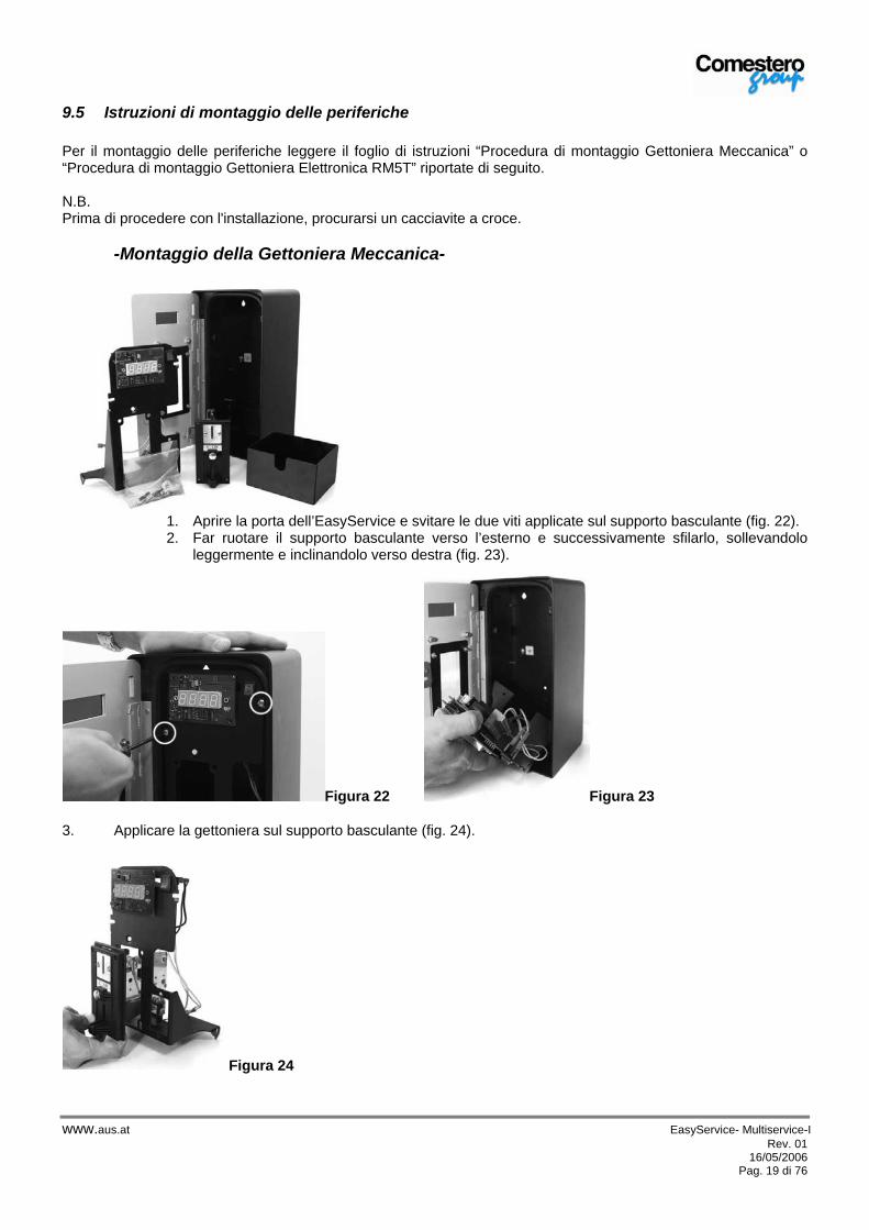
9.5 Istruzioni di montaggio delle periferiche Per il montaggio delle periferiche leggere il foglio di istruzioni “Procedura di montaggio Gettoniera Meccanica” o “Procedura di montaggio Gettoniera Elettronica RM5T” riportate di seguito. N.B. Prima di procedere con l'installazione, procurarsi un cacciavite a croce. -Montaggio della Gettoniera Meccanica-
1. Aprire la porta dell’EasyService e svitare le due viti applicate sul supporto basculante (fig. 22). 2. Far ruotare il supporto basculante verso l’esterno e successivamente sfilarlo, sollevandolo
leggermente e inclinandolo verso destra (fig. 23).
Figura 22 Figura 23
3. Applicare la gettoniera sul supporto basculante (fig. 24).
Figura 24
alfred
A.u.S.Spielgeräte GmbH

www.aus.at EasyService- Multiservice-I Rev. 01 16/05/2006
Pag. 20 di 76
Figura 25
4. Inserire una vite, utilizzando quelle fornite, nell’apposito foro del frontale (fig. 25).
5. Ruotare il supporto basculante, tenendo la vite inserita, posizionare la rondella e avvitare il dado (fig. 26). Ripetere le operazioni 4 e 5 con le viti rimanenti.
Figura 26 Figura 27
6. Utilizzare i due fili collegati alla scheda elettronica TDM, connettore 2poli. Inserirne uno dei due nel contatto COMUNE (n°1) e l’altro nel contatto NO* (n°3) della gettoniera (fig. 27).
* NO: Normalmente aperto
7. Riposizionare il supporto basculante e fissarlo con le apposite viti avendo cura di centrare il display nella finestrella dello sportello (fig. 28).
Figura 28
alfred
A.u.S.Spielgeräte GmbH

www.aus.at EasyService- Multiservice-I Rev. 01 16/05/2006
Pag. 21 di 76
-Montaggio della Gettoniera Elettronica-
1. Aprire la porta dell’EasyService e svitare le due viti applicate sul supporto basculante (fig. 29).
Figura 29
2. Far ruotare il supporto basculante verso l’esterno e successivamente sfilarlo, sollevandolo leggermente e inclinandolo verso destra (fig. 30).
Figura 30
3. Collegare tutti i cablaggi ai relativi connettori, vedi figura 31, 32 e 33
Figura 31 (Tasti) Figura 32 (Alim.)
alfred
A.u.S.Spielgeräte GmbH

www.aus.at EasyService- Multiservice-I Rev. 01 16/05/2006
Pag. 22 di 76
Figura 33 (Display)
4. Applicare la gettoniera sul supporto basculante (fig. 34).
Figura 34
5. Riposizionare il supporto basculante e fissarlo con le apposite viti avendo cura di centrare il display nella finestrella dello sportello (fig. 28).
10 Funzionamento e programmazione
10.1 CON GETTONIERA MECCANICA NOTE GENERALI L’EASY SERVICE ,“con gettoniera meccanica”, costituisce una scatola di pilotaggio in grado di attivare un servizio temporizzato. Esso è programmabile per un valore che va da 1 secondo fino a 24 ore. E’ composto da una gettoniera meccanica in grado di accettare un solo tipo di gettone/moneta.
10.2 Funzionamento normale Nel normale funzionamento, a riposo, il display della macchina mostra sull’ultima cifra uno zero, indica che è in attesa dell’inserimento di un gettone/moneta. All’inserimento della moneta la macchina visualizza sul display un numero, il numero rappresenta il conteggio delle monete che si stanno inserendo, prima del raggiungimento del prezzo del servizio. Se questo numero coincide con l’unità, al suo posto apparirà solo il tempo di attivazione del servizio. Nel caso in cui sia stato programmato l’utilizzo del pulsante di START la macchina, alla ricezione del gettone/moneta, visualizzerà il tempo, senza far partire il servizio, fino alla pressione del pulsante. A servizio avviato, con entrambe le modalità di funzionamento, una pressione del pulsante di START (se presente) interrompe, momentaneamente, il servizio fino alla sua successiva pressione, la quale fa ripartire il servizio (Economizzatore). Durante la fase “Pausa” del servizio il tempo non viene decrementato. La scheda prevede un uscita a relè per il tempo di preavviso. Il relè di preavviso si attiva “x” secondi prima dello scadere del tempo di servizio. Il tempo “x” è configurabile per un tempo massimo di 99 minuti, si disattiva alla fine del conteggio del servizio.
alfred
A.u.S.Spielgeräte GmbH

www.aus.at EasyService- Multiservice-I Rev. 01 16/05/2006
Pag. 23 di 76
Il diagramma temporale seguente mostra quanto descritto.
CONTATTO GETTONIERA
RELE’ SERVIZIO
RELE’ PREAVVISO
T1
T2
T1 = 20mST2 = 94mS
10.3 Procedura generale di impostazioni parametri Questa modalità serve per programmare i parametri di funzionamento della macchina e il tempo di durata del servizio. La prima volta che si entra in questa modalità, i vari parametri modificabili mostrano il valore di default. Le successive volte che si programmerà il dispositivo, verrà mostrato il valore programmato in precedenza, e sarà possibile confermare lo stesso valore semplicemente tenendo premuto il pulsante.
I parametri programmabili sono i seguenti: • Tempo di conteggio: ore, minuti e secondi. Minimo 1 secondo massimo 24 ore. • Tempo di preavviso: minuti e secondi. Minimo 1 secondo massimo 99 minuti. • Numero di monete da inserire, per il raggiungimento del valore del servizio. • Impostazione del modo di lavoro del contatto della gettoniera: NO o NC (normally open, normally closed ) • Abilitazione pulsante START
Per entrare nella modalità di programmazione bisognerà: 1. Spegnere la macchina 2. Tenere premuto con un astuccio di una penna, il pulsante SW1, posto sul davanti della scheda vedi
figura 35.
Figura 35
alfred
A.u.S.Spielgeräte GmbH

www.aus.at EasyService- Multiservice-I Rev. 01 16/05/2006
Pag. 24 di 76
3. Riaccendere la macchina contemporaneamente alla pressione del pulsante, e tenerlo premuto fino al lampeggio del primo parametro “H_00“. Il tempo di attesa è, pressappoco, di 6 secondi.
Per modificare il valore del parametro, selezionato, premere il pulsante brevemente. Una volta raggiunto il valore, desiderato, passare al parametro successivo per salvare il nuovo dato. Per eseguire questa operazione tenere premuto il pulsante a lungo, verificare che il lampeggio si sposti al parametro successivo. Un esempio di programmazione è riportato di seguito.
10.4 Programmazione durata del servizio
10.5 Settaggio del tempo
DISPLAY
PULSANTE
AZIONE
“H_00“ ( lampeggia prima cifra) Pressione pulsante breve Incremento “H _01“ ( lampeggia prima cifra) Pressione pulsante breve Incremento “H _02“ ( lampeggia prima cifra) Pressione pulsante lunga Avanza al prossimo parametro
“H _02“ ( lampeggia seconda cifra) Pressione pulsante breve Incremento “H _12“ ( lampeggia seconda cifra) Pressione pulsante breve Incremento “H _22“ ( lampeggia seconda cifra) Pressione pulsante breve Incremento “H _22“ ( lampeggia seconda cifra) Pressione pulsante lunga
Avanza al prossimo parametro
“n_00“ ( lampeggia prima cifra) Pressione pulsante breve Incremento “n_01“ ( lampeggia prima cifra) Pressione pulsante breve Incremento “n_02“ ( lampeggia prima cifra) Pressione pulsante lunga Avanza al prossimo parametro
“n_02“ ( lampeggia seconda cifra) Pressione pulsante lunga Avanza al prossimo parametro
“S_00“ ( lampeggia seconda cifra) Pressione pulsante breve Incremento “S_01“ ( lampeggia seconda cifra) Pressione pulsante breve Incremento “S_02“ ( lampeggia seconda cifra) Pressione pulsante breve Incremento “S_02“ ( lampeggia seconda cifra) Pressione pulsante lunga Avanza al prossimo parametro
“S_12“ ( lampeggia prima cifra) Pressione pulsante breve Incremento “S_22“ ( lampeggia prima cifra) Pressione pulsante breve Incremento “S_32“ ( lampeggia prima cifra) Pressione pulsante lunga Avanza al prossimo parametro
…. Tabella dei simboli: H = ore n = minuti S = secondi
Nell’esempio sopra riportato è stato impostato un tempo di durata del servizio di 22 Ore 2 Minuti e 32 secondi. Il valore di DEFAULT di questo parametro è 00:00:06 (6 secondi)
alfred
A.u.S.Spielgeräte GmbH
www.aus.at EasyService- Multiservice-I Rev. 01 16/05/2006
Pag. 25 di 76
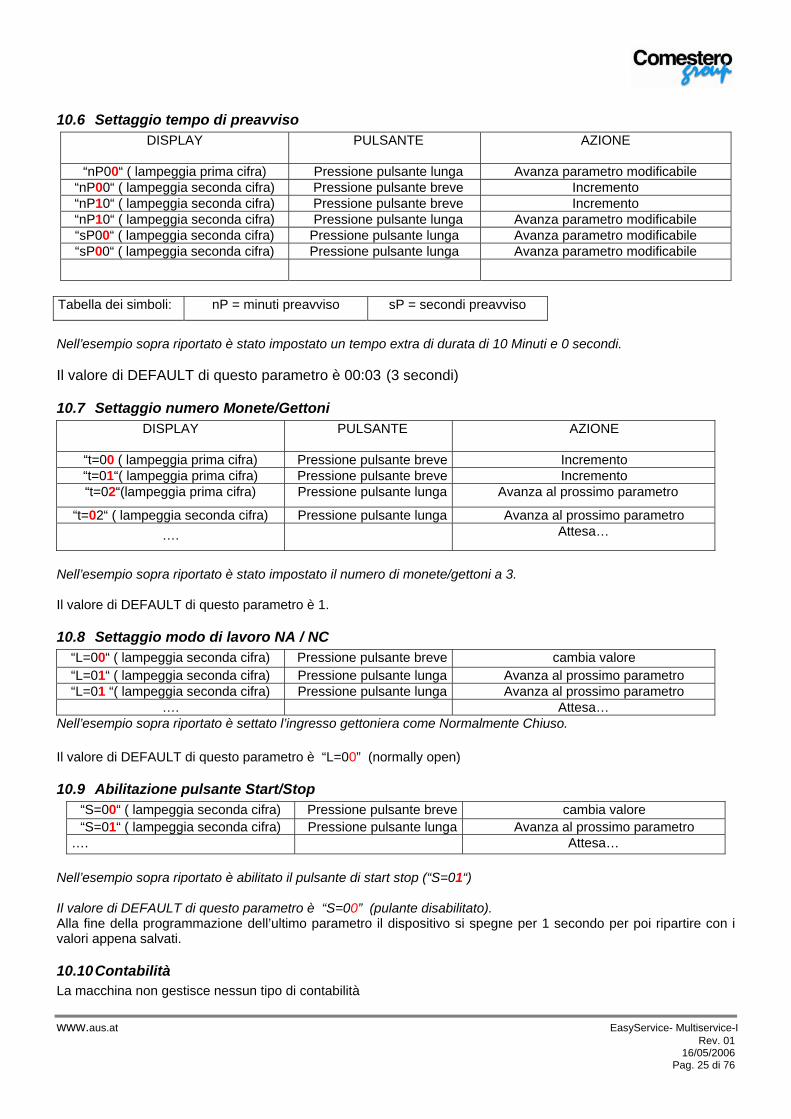
10.6 Settaggio tempo di preavviso DISPLAY
PULSANTE
AZIONE
“nP00“ ( lampeggia prima cifra) Pressione pulsante lunga Avanza parametro modificabile
“nP00“ ( lampeggia seconda cifra) Pressione pulsante breve Incremento “nP10“ ( lampeggia seconda cifra) Pressione pulsante breve Incremento “nP10“ ( lampeggia seconda cifra) Pressione pulsante lunga Avanza parametro modificabile “sP00“ ( lampeggia seconda cifra) Pressione pulsante lunga Avanza parametro modificabile “sP00“ ( lampeggia seconda cifra) Pressione pulsante lunga Avanza parametro modificabile
Tabella dei simboli: nP = minuti preavviso sP = secondi preavviso
Nell’esempio sopra riportato è stato impostato un tempo extra di durata di 10 Minuti e 0 secondi. Il valore di DEFAULT di questo parametro è 00:03 (3 secondi)
10.7 Settaggio numero Monete/Gettoni DISPLAY
PULSANTE
AZIONE
“t=00 ( lampeggia prima cifra) Pressione pulsante breve Incremento “t=01“( lampeggia prima cifra) Pressione pulsante breve Incremento “t=02“(lampeggia prima cifra) Pressione pulsante lunga Avanza al prossimo parametro
“t=02“ ( lampeggia seconda cifra) Pressione pulsante lunga Avanza al prossimo parametro …. Attesa…
Nell’esempio sopra riportato è stato impostato il numero di monete/gettoni a 3. Il valore di DEFAULT di questo parametro è 1.
10.8 Settaggio modo di lavoro NA / NC “L=00“ ( lampeggia seconda cifra) Pressione pulsante breve cambia valore “L=01“ ( lampeggia seconda cifra) Pressione pulsante lunga Avanza al prossimo parametro “L=01 “( lampeggia seconda cifra) Pressione pulsante lunga Avanza al prossimo parametro
…. Attesa… Nell’esempio sopra riportato è settato l’ingresso gettoniera come Normalmente Chiuso. Il valore di DEFAULT di questo parametro è “L=00” (normally open)
10.9 Abilitazione pulsante Start/Stop “S=00“ ( lampeggia seconda cifra) Pressione pulsante breve cambia valore “S=01“ ( lampeggia seconda cifra) Pressione pulsante lunga Avanza al prossimo parametro
…. Attesa… Nell’esempio sopra riportato è abilitato il pulsante di start stop (“S=01“) Il valore di DEFAULT di questo parametro è “S=00” (pulante disabilitato). Alla fine della programmazione dell’ultimo parametro il dispositivo si spegne per 1 secondo per poi ripartire con i valori appena salvati.
10.10 Contabilità La macchina non gestisce nessun tipo di contabilità
alfred
A.u.S.Spielgeräte GmbH

www.aus.at EasyService- Multiservice-I Rev. 01 16/05/2006
Pag. 26 di 76
11 Schema di collegamento
NC
NO
COM
NC
NOCOM
SCHEDA ELETTRONICA ATM
GETTONIERA
INGRESSO GETTONIERA
INTERRUTTORE BIPOLARE
GROUND
FASE
NEUTRO
INGRESSO 230Vac
USCITA RELE’ SERVIZIO
USCITA RELE’ PREAVVISO
J1
J6
J3
J5
J4
EASY SERVICE
BIANCO
BIANCO
1
1
1
1
2
3
2
3
2
2 3
21
TERRA
alfred
A.u.S.Spielgeräte GmbH

www.aus.at EasyService- Multiservice-I Rev. 01 16/05/2006
Pag. 27 di 76
12 Funzionamento e programmazione
12.1 CON GETTONIERA ELETTRONICA NOTE GENERALI IL MULTISERVICE A DUE SERVIZI “con gettoniera elettronica” è un dispositivo di pilotaggio in grado di attivare uno o due servizi temporizzati. E’ composto da una gettoniera elettronica in grado di accettare varie tipologie di gettoni e/o monete.
12.2 Caratteristiche generali La gettoniere RM5T può essere programmata (utilizzando il programma Clone 5 vedi punto 12.9) per svolgere diverse funzioni che sono:
Timer progressivo: esegue la temporizzazione di un servizio proporzionale al credito accumulato. Timer progressivo con richiesta del servizio: esegue la temporizzazione di un servizio proporzionale al
credito accumulato, l’attivazione del servizio viene effettuata con il tasto montato sul frontale del Box. Doppio timer progressivo: esegue fino a due temporizzazioni distinte i cui tempi sono legati al credito
accumulato. L’attivazione viene effettuata con i due tasti montati sul frontale del Box. I paragrafi successivi spiegano in dettaglio i tre diversi modi di funzionamento.
12.3 Funzionamento normale Timer progressivo Riconosce 59 monete che possono avere anche 59 valori diversi, ne effettua la somma e quando raggiunge un valore prefissato (costo base servizio) abilita un segnale per un tempo definito (tempo base del servizio). Aggiungendo altre monete la durata del segnale viene aumentata, proporzionalmente al valore delle monete aggiunte. La gettoniera gestisce un display che visualizza le monete inserite fino a quando non si raggiunge il costo base e dopo visualizza il tempo in secondi oppure in minuti. E' previsto un segnale di uscita per la segnalazione di preavviso di scadenza del tempo disponibile, il tempo di preavviso è regolabile. E’ possibile, con i sistemi di programmazione, attivare l’uscita del Preavviso come Contatore Monete. Il numero di chiusure del contatto è uguale a: Totale introdotto . Valore base E' previsto anche un segnale in ingresso detto economizzatore, questo segnale blocca il tempo sospendendo il relativo comando in uscita. Togliendo il suddetto segnale, la gettoniera riabilita il servizio ed il conteggio del tempo.
alfred
A.u.S.Spielgeräte GmbH

www.aus.at EasyService- Multiservice-I Rev. 01 16/05/2006
Pag. 28 di 76
12.3.1 Programmazione in locale per la modalità Timer progressivo E’ possibile configurare alcuni parametri, della gettoniera, usando i due tasti ed il display. Per accedere alla programmazione e impostare i valori procedere come descritto di seguito. Durante l’editing delle cifre il punto decimale viene utilizzato per indicare quale delle cifre è attualmente selezionata. Descrizione Display Tasti gettoniera spenta spento attivati accensione gettoniera attivati ingresso in configurazione 3030 (lampeggiante) attivati
disattivati 1 (lampeggiante)
impostazione della prima cifra del prezzo 1.234 ingresso 1 incrementa le migliaia ingresso 2 passa alle centinaia
impostazione della seconda cifra del prezzo 12.34 ingresso 1 incrementa le centinaia ingresso 2 passa alle decine
impostazione della terza cifra del prezzo 123.4 ingresso 1 incrementa le decine ingresso 2 passa alle unità
impostazione della quarta cifra del prezzo 1234. ingresso 1 incrementa le unità ingresso 2 passa al campo successivo
2 (lampeggiante)
impostazione della prima cifra del tempo 1.234 ingresso 1 incrementa le migliaia ingresso 2 passa alle centinaia
impostazione della seconda cifra del tempo 12.34 ingresso 1 incrementa le centinaia ingresso 2 passa alle decine
impostazione della terza cifra del tempo 123.4 ingresso 1 incrementa le decine ingresso 2 passa alle unità
impostazione della quarta cifra del tempo 1234. ingresso 1 incrementa le unità ingresso 2 passa al campo successivo
3 (lampeggiante)
impostazione della prima cifra del tempo di preavviso
1.234 ingresso 1 incrementa le migliaia ingresso 2 passa alle centinaia
impostazione della seconda cifra del tempo di preavviso
12.34 ingresso 1 incrementa le centinaia ingresso 2 passa alle decine
impostazione della terza cifra del tempo di preavviso
123.4 ingresso 1 incrementa le decine ingresso 2 passa alle unità
impostazione della quarta cifra del tempo di preavviso
1234. ingresso 1 incrementa le unità ingresso 2 passa al campo successivo
9999 (lampeggiante)
fine della configurazione. Spegnere e riaccendere la gettoniera per rendere operative le nuove impostazioni
Per rendere operative le nuove impostazioni è necessario togliere e ripristinare l’alimentazione della gettoniera.
12.4 Funzionamento normale Timer progressivo con richiesta del servizio L’unica differenza rispetto alla versione Timer progressivo, punto 12.3, è che: il segnale temporizzato verrà emesso solo a richiesta del cliente premendo il pulsante (1) del BOX.
12.4.1 Programmazione locale per la modalità Timer progressivo con richiesta del servizio Per la programmazione vale quanto scritto nel punto 12.3.1 .
12.5 Funzionamento normale Doppio timer progressivo Descrizione funzionale Lato Clone 5
alfred
A.u.S.Spielgeräte GmbH

www.aus.at EasyService- Multiservice-I Rev. 01 16/05/2006
Pag. 29 di 76
Usata come doppio timer progressivo la gettoniera permette di acquistare dei tempi di erogazione su due linee di uscita. In pratica l’utente inserisce delle monete (o gettoni) il cui valore viene accumulato.
I prezzi delle erogazioni vengono impostati i campi Prezzo 1 / Tempo 1 per l’uscita 1 e Prezzo 2 / Tempo 2 per l’uscita 2. In generale il Prezzo 1 (o 2) indica quanti prezzi base devono essere accumulati per comprare un erogazione di durata pari a Tempo 1 (o 2)
Se entrambi gli ingressi sono attivi in assenza di credito, viene inibita l’accettazione di nuove monete.
Quando viene attivato uno degli ingressi il credito accumulato viene convertito in tempo e l’uscita associata all’ingresso selezionato rimane attiva per il tempo acquistato. Se sull’uscita era già in corso una temporizzazione il nuovo tempo calcolato viene sommato a quello già in corso.
Per decidere se l’attivazione di un ingresso coincide con la chiusura o con l’apertura del contatto relativo usare il campo Attivazione alta. Se questo campo viene abilitato, l’ingresso viene considerato attivo quando il contatto è aperto.
E’ possibile fare in modo che il credito iniziale per attivare l’erogazione sia superiore agli incrementi successivi che vengono convertiti in tempo di erogazione.
Il campo Aggiunta minima indica gli incrementi successivi al prezzo di partenza dell’erogazione. L’aggiunta minima è comune per entrambi i timer.
Quando viene attivato uno degli ingressi, per 5 secondi, il display mostra il conto alla rovescia sul timer relativo.
La gettoniera può essere configurata per considerare attivo l’ingresso quando il contatto è chiuso oppure quando il contatto è aperto
Se si abilita il campo Attivazione alta, l’ingresso viene considerato attivo alla chiusura del contatto relativo. Viceversa se il campo è disabilitato.
I tempi possono essere espressi in secondi o minuti. Il conto alla rovescia, visualizzato all’attivazione dell’ingresso, viene mostrato in minuti o secondi coerentemente con le impostazioni effettuate. Comunque l’ultimo minuto della temporizzazione viene sempre mostrato in secondi.
La selezione si effettua mediante il campo Tempo in minuti
Il credito può essere accumulato fino ad un valore massimo pari a 220 volte il prezzo base. Una volta raggiunto tale valore ogni nuova moneta/gettone viene rifiutata.
Il tempo massimo accumulabile è pari a 65000 secondi.
E’ possibile attivare una funzione d’antifrode che, nel caso si tentino manovre di frode, blocca la gettoniera per un tempo impostato dopodiché azzera la gettoniera cancellando il credito accumulato e le temporizzazioni in corso. Durante il periodo in cui la gettoniera è disabilitata le erogazioni vengono sospese e le monete rifiutate.
Per attivare questa funzionalità si deve abilitare il campo Inib nella sezione “Anti-frode”. Il campo numerico presente nella sezione “Anti-frode” consente di impostare il tempo (in secondi) di blocco della gettoniera prima che riprenda a funzionare.
Il diagramma che segue mostra un esempio di funzionamento del doppio timer. L’esempio mostra il comportamento dell’Uscita 1 e del Timer 1in funzione dell’attività sull’Ingresso 1, ma le stesse considerazioni valgono nel caso di Uscita2 / Timer 2 / Ingresso 2..
Uscita 1
Timer 1
Ingresso 1
Credito accumulato
A B C
1. viene accumulato del credito (mostrato sul diagramma credito accumulato)
2. l’impulso sul diagramma Ingresso 1 mostra l’attivazione dell’ingresso (indicato con la A) ed il credito viene convertito in tempo (si immagina che la conversione non dia luogo a credito residuo dopo la conversione).Sul diagramma Timer 1 si vede che il tempo è caricato dopodiché comincia a scorrere.In corrispondenza del caricamento del tempo viene attivata l’Uscita 1.
3. viene quindi inserito ulteriore credito… 4. e viene attivato di nuovo l’ingresso (impulso B).
Anche in questo caso il credito viene convertito in tempo che viene caricato sul timer.Di conseguenza il tempo associato al Timer 1 viene incrementato del risultato della nuova conversione Credito / Tempo.
5. Il tempo continua a scorrere fino a che arriva a 0.Di conseguenza l’Uscita 1 viene disattivata.
alfred
A.u.S.Spielgeräte GmbH

www.aus.at EasyService- Multiservice-I Rev. 01 16/05/2006
Pag. 30 di 76
12.6 Programmazione locale per la modalità Doppio timer progressivo E’ possibile configurare alcuni parametri, della gettoniera, usando i due tasti ed il display. Per utilizzare questa funzione seguire la procedura che segue. Nella colonna ingressi viene indicato se sono attivati o meno, questo perché gli ingressi possono essere attivi chiusi o attivi aperti a seconda di come è stata impostata la polarità di funzionamento (campo “Attivazione alta” in Clone5). Durante l’editing delle cifre il punto decimale viene utilizzato per indicare quale delle cifre è attualmente selezionata.
Descrizione Display Ingressi gettoniera spenta spento attivati accensione gettoniera attivati ingresso in configurazione 3232 (lampeggiante) attivati
disattivati 1 (lampeggiante)
impostazione della prima cifra del prezzo 1 1.234 ingresso 1 incrementa le migliaia ingresso 2 passa alle centinaia
impostazione della seconda cifra del prezzo 1 12.34 ingresso 1 incrementa le centinaia ingresso 2 passa alle decine
impostazione della terza cifra del prezzo 1 123.4 ingresso 1 incrementa le decine ingresso 2 passa alle unità
impostazione della quarta cifra del prezzo 1 1234. ingresso 1 incrementa le unità ingresso 2 passa al campo successivo
2 (lampeggiante)
impostazione della prima cifra del tempo 1 1.234 ingresso 1 incrementa le migliaia ingresso 2 passa alle centinaia
impostazione della seconda cifra del tempo 1 12.34 ingresso 1 incrementa le centinaia ingresso 2 passa alle decine
impostazione della terza cifra del tempo 1 123.4 ingresso 1 incrementa le decine ingresso 2 passa alle unità
impostazione della quarta cifra del tempo 1 1234. ingresso 1 incrementa le unità ingresso 2 passa al campo successivo
3 (lampeggiante)
impostazione della prima cifra del prezzo 2 1.234 ingresso 1 incrementa le migliaia ingresso 2 passa alle centinaia
impostazione della seconda cifra del prezzo 2 12.34 ingresso 1 incrementa le centinaia ingresso 2 passa alle decine
impostazione della terza cifra del prezzo 2 123.4 ingresso 1 incrementa le decine ingresso 2 passa alle unità
impostazione dalla quarta cifra del prezzo 2 1234. ingresso 1 incrementa le unità ingresso 2 passa al campo successivo
4 (lampeggiante) impostazione della prima cifra del tempo 2 1.234 ingresso 1 incrementa le migliaia
ingresso 2 passa alle centinaia impostazione della seconda cifra del tempo 2 12.34 ingresso 1 incrementa le centinaia
ingresso 2 passa alle decine impostazione della terza cifra del tempo 2 123.4 ingresso 1 incrementa le decine
ingresso 2 passa alle unità impostazione dalla quarta cifra del tempo 2 1234. ingresso 1 incrementa le unità
ingresso 2 passa al campo successivo 9999 (lampeggiante)
fine della configurazione. Spegnere e riaccendere la gettoniera per rendere operative le nuove impostazioni
Durante la programmazione tenere presenti i seguenti controlli che vengono effettuati:
se incrementando una cifra si eccede il massimo consentito per il parametro in fase di impostazione, la cifra passa a 0. - Ad esempio, se si stanno impostando le centinaia di un numero il cui valore è 199, ed il cui massimo è 200, allora il valore successivo sarà 99.
il valore di incremento minimo di un prezzo è pari al valore base. Per questo se il valore base è 10, non si potranno impostare le unità del prezzo, ma solo le migliaia, le centinaia e le decine. le impostazioni dei tempi sono in minuti o secondi coerentemente con la configurazione della gettoniera (campo “Durata servizio in sec/min” in Clone5).
alfred
A.u.S.Spielgeräte GmbH

www.aus.at EasyService- Multiservice-I Rev. 01 16/05/2006
Pag. 31 di 76
12.7 Programmazione con Clone 5 L’immagine che segue mostra la pagina di Clone 5 nel caso sia stata selezionata l’opzione timer progressivo con doppia attivazione esterna, che determina il comportamento da doppio timer progressivo.
Di seguito viene riassunto lo scopo delle impostazioni disponibili. L’elenco riporta il nome dei singoli campi e la descrizione relativa.
Campo Descrizione RM5 T 30 – Tot. timer se attivato permette di accedere alle impostazioni per usare la gettoniera come
timer progressivo 3R – Attivazione esterna Deve essere abilitato per potere accedere all’abilitazione del doppio reset
esterno Doppia attivazione esterna Se abilitato indica che i due ingressi della gettoniera vengono usati come
attivazione per i due timer Attivazione alta Permette di selezionare la polarità degli ingressi che attiva i timer.
Se questo campo è abilitato gli ingressi vengono considerati attivi quando il contatto è aperto, viceversa se il campo non viene abilitato. Se si utilizzano i tasti del BOX non deve essere selezionata.
Display off Se questo campo viene attivato, il display non viene più aggiornato. Tempo in minuti Se questo campo viene attivato significa che i tempi vengono espressi (e
visualizzati) in minuti, altrimenti vengono trattati come secondi.
Configurazione
Anti frode Permette di abilitare un sistema di antifrode della gettoniera. Se viene identificato un tentativo di frode la gettoniera viene bloccata per il tempo impostato nel campo di editing numerico.
Prezzo 1 Relativamente all’uscita 1, rappresenta l’importo necessario per un’erogazione della durata indicata nel campo successivo.
Durata servizio in sec/min Tempo di erogazione corrispondente al prezzo indicato al campo precedente. In questo caso vale per l’uscita 1
Prezzo 2 Relativamente all’uscita 2, rappresenta l’importo necessario per un’erogazione della durata indicata nel campo successivo.
Programmazione
Durata servizio in sec/min Tempo di erogazione corrispondente al prezzo indicato al campo precedente. In questo caso vale per l’uscita 2
12.8 Contabilità Sulla gettoniera elettronica è possibile attivare un contatore. Esso mostra il valore totale delle monete introdotte. L’opzione è attuabile da programma Clone5 ed possibile leggere il valore contabilizzato sempre sul programma.
13 Strumenti e accessori (solo per le versioni con gettoniera RM5T) Qui di seguito viene riportata la lista di tutti gli strumenti ed accessori disponibili:
alfred
A.u.S.Spielgeräte GmbH

www.aus.at EasyService- Multiservice-I Rev. 01 16/05/2006
Pag. 32 di 76
1) Kit di programmazione per P.C., codice per ordine RMPRKIT5, composto da:
1) Software di programmazione “Clone5” 2) Interfaccia seriale RS232 per gettoniera RM5 3) Supporto per la programmazione della gettoniera 4) Test Box per verifica delle uscite 5) Alimentatore universale 12V - 1A
2) Cablaggio supplementare, per la remotizzazione dei pulsanti di START : a) cablaggio ingressi RM5T codice RM5T-500
14 Schema di collegamento
-V
P1
USCITA
SERVIZIO 2
JP5
HEADER 6
123456
DISPLAY fSE924-2
P1
T1
24V
ac 1
5 V
A
1 4
5 6 8
HEADER 7
1234567
FUSE
P3
P2
JP1
1 2NEUTRO
P2
KPA
FASE
INGRESSO 230 Vac 50Hz
P4
COMUNE
NEUT
RO
P5
GROUND
TASTIERA KEY 6 TASTI
JP7
1 2 3 4
NO 1
JP6
HEADER 3
123
FILTRO RETE
21
3
NERO
COMUNE 1
HEADER 8
6 5 4 3 2 1 C C
JP2
1 2
13
24
P6
NC 1
EASY SERVICE RM5T
NC 2
JP4
HEADER 2
12
ROSSO
COMUNE 2
21
3
GIALLO
RM5 T
BIANCO
NO 2FUS
E 1
A T
INTERRUTTOREBIPOLARE
FASE
+V
USCITA
SERVIZIO 1
15 Funzionamento e programmazione
15.1 CON SISTEMA CHIAVE E GETTONIERA ELETTRONICA NOTE GENERALI Il MULTI SERVICE a sei servizi “con sistema chiave” è una scatola di comando in grado di gestire fino a sei attuazioni temporizzate . E’ costituito da: un sistema chiave, una gettoniera elettronica e due schede di comando.
alfred
A.u.S.Spielgeräte GmbH
www.aus.at EasyService- Multiservice-I Rev. 01 16/05/2006
Pag. 33 di 76
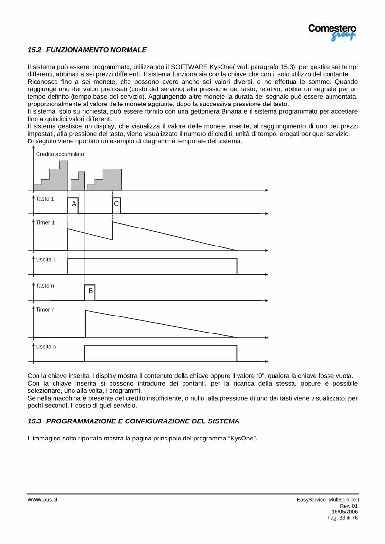
15.2 FUNZIONAMENTO NORMALE Il sistema può essere programmato, utilizzando il SOFTWARE KysOne( vedi paragrafo 15.3), per gestire sei tempi differenti, abbinati a sei prezzi differenti. Il sistema funziona sia con la chiave che con il solo utilizzo del contante. Riconosce fino a sei monete, che possono avere anche sei valori diversi, e ne effettua le somme. Quando raggiunge uno dei valori prefissati (costo del servizio) alla pressione del tasto, relativo, abilita un segnale per un tempo definito (tempo base del servizio). Aggiungendo altre monete la durata del segnale può essere aumentata, proporzionalmente al valore delle monete aggiunte, dopo la successiva pressione del tasto. Il sistema, solo su richiesta, può essere fornito con una gettoniera Binaria e il sistema programmato per accettare fino a quindici valori differenti. Il sistema gestisce un display, che visualizza il valore delle monete inserite, al raggiungimento di uno dei prezzi impostati, alla pressione del tasto, viene visualizzato il numero di crediti, unità di tempo, erogati per quel servizio. Di seguito viene riportato un esempio di diagramma temporale del sistema.
Uscita 1
Timer 1
Tasto 1A C
Credito accumulato
Uscita n
Tasto nB
Con la chiave inserita il display mostra il contenuto della chiave oppure il valore “0”, qualora la chiave fosse vuota. Con la chiave inserita si possono introdurre dei contanti, per la ricarica della stessa, oppure è possibile selezionare, uno alla volta, i programmi. Se nella macchina è presente del credito insufficiente, o nullo ,alla pressione di uno dei tasti viene visualizzato, per pochi secondi, il costo di quel servizio.
15.3 PROGRAMMAZIONE E CONFIGURAZIONE DEL SISTEMA L’immagine sotto riportata mostra la pagina principale del programma “KysOne”.
alfred
A.u.S.Spielgeräte GmbH

www.aus.at EasyService- Multiservice-I Rev. 01 16/05/2006
Pag. 34 di 76
Pulsante perimpostare i tempi
Pulsante per impostare i prezzi
Gestione della MancataVendita
Sistema Audit“Contabilità”
Gestione Venditain Contanti
Valore Massimocaricabile in chiave
Qui sotto è riportata una tabella riassuntiva delle funzioni principali disponibili sulla chiave: Voci di Configurazione Descrizione
Codici E’ possibile, e consigliabile, impostare i codici di identificazione. I codici sono Gestore, Locazione e Macchina.
Vendita in contanti Singola
Introducendo soldi in contanti, per un livello superiore al valore del servizio, selezionando il servizio il resto viene tolto e contabilizzato, in un contatore dedicato.
Vendita in contanti Multipla
Introducendo soldi in contanti, per un livello superiore al valore del servizio, selezionando il servizio il resto viene lasciato a disposizione, senza limite di tempo.
Vendita in contanti Multipla a Tempo
Introducendo soldi in contanti, per un livello superiore al valore del servizio, selezionando il servizio il resto viene lasciato a disposizione per un tempo prestabilito, impostabile in secondi, scaduto il quale viene tolto e contabilizzato.
Gestione Mancata vendita Mantiene Credito
Quando una vendita non va a buon fine il credito viene restituito a display
Gestione Mancata vendita Mancata Vendita
Quando una vendita non va a buon fine il credito viene tolto e contabilizzato, in un contatore dedicato.
Chiave di Ricarica E’ possibile attivare e gestire una chiave di ricarica. Una chiave, con un valore prestabilito, che lascia, ogni volta che la si utilizza sul sistema, una valore determinato (es. 5 €). L’utente finale può caricare questo valore sulla sua chiave, introducendola nel sistema.
Chiave di Configurazione E’ possibile attivare e gestire una chiave di Configurazione. Una chiave che permette di modificare, se necessario, i valori del sistema senza la presenza del PC sul sito ove si trova l’apparecchio.
Voci di Programmazione Descrizione
Prezzi E’ possibile impostare fino a 6 prezzi, di valore uguale o differente, ed associarli a dei tempi prestabiliti, vedi riga sotto.
Tempi E’ possibile impostare fino a 6 tempi, di valore uguale o differente, ed associarli a dei prezzi prestabiliti, vedi riga sopra.
15.4 PROGRAMMAZIONE LOCALE DELLA GETTONIERA La funzione di SELF-PROG è utilissima quando si vuole programmare una moneta o un gettone direttamente sulle macchine su cui le gettoniere sono state installate, in quanto i primi sei canali della gettoniera RM5 possono essere
alfred
A.u.S.Spielgeräte GmbH

www.aus.at EasyService- Multiservice-I Rev. 01 16/05/2006
Pag. 35 di 76
riprogrammati senza l'ausilio di apparecchiature esterne. Ricordiamo che oltre alla programmazione della moneta/gettone sullo specifico canale, può essere necessario modificare altri parametri della gettoniera, quali ad esempio l’attribuzione di valori, in questo caso bisogna obbligatoriamente utilizzare o il Taratore Portatile o il Kit PC. Programmazione del gettone o della moneta sul canale 6
• A macchina spenta porre i 6 DIP-SWITCH della gettoniera in ON
• Alimentare e inserire 15 monete / gettoni.
• Attendere il doppio “clack” di fine programmazione
• Porre gli interruttori del DIP in OFF
• Spegnere e riaccendere la gettoniera Programmazione gettoni e/o monete su canali da 1 a 5
• A macchina spenta porre i 6 DIP-SWITCH della gettoniera in ON
• Alimentare e inserire 1 o 2 monete
• Lasciare in ON solo lo SWITCH corrispondente al canale da programmare
• Inserire monete fino al doppio “clack” di fine programmazione
• Porre gli interruttori del DIP in OFF
• Spegnere e riaccendere la gettoniera NOTA: A procedura eseguita le prime due monete introdotte potrebbero essere scartate.
Con questa operazione la nuova taratura (moneta/gettone) manterrà il valore precedentemente programmato. Verificare che la posizione del canale dove è stata effettuata la nuova taratura sia compatibile con la tabella valori del Sistema Chiave.
15.5 TARATORE PORTATILE PER GETTONIERA (OPZIONALE) Oltre a poter modificare sul campo tutte le funzioni della gettoniera, comprende anche la funzione di “CLONING”. Tale funzione permette di prelevare i dati da una gettoniera, o da un PC e di trasferirli in un'altra, rendendola così identica alla prima: taratura, configurazione e opzioni comprese.
15.6 CONTABILITA’ Sul sistema chiave sono presenti vari menù di contabilità, la contabilità è sempre attiva. Il sistema è in grado di conservare le seguenti letture:
• Numero delle monete introdotte, per tipologia • Totale delle monete introdotte • Numero delle vendite effettuate, per prezzo di vendita • Totale delle vendite effettuate • Totale del valore caricato nelle chiavi • Totale del valore scaricato dalle chiavi • Totale dei Bonus effettuati, se abilitati • Totale delle vendite Gratuite, se abilitate • Totale Sconto applicato nelle fasce orarie “Happy hours” , se abilitate • …
Lo strumento per leggere la contabilità della macchina è il programma “KysOne”. Segue un esempio di lettura contabilità effettuato su un sistema.
alfred
A.u.S.Spielgeräte GmbH
www.aus.at EasyService- Multiservice-I Rev. 01 16/05/2006
Pag. 36 di 76
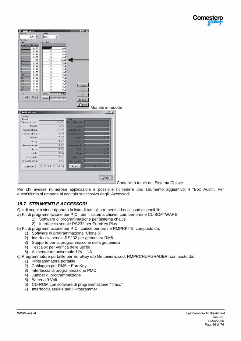
Monete introdotte
Contabilità totale del Sistema Chiave
Per chi avesse numerose applicazioni è possibile richiedere uno strumento aggiuntivo: il “Box Audit”. Per quest’ultimo si rimanda al capitolo successivo degli “Accessori”.
15.7 STRUMENTI E ACCESSORI Qui di seguito viene riportata la lista di tutti gli strumenti ed accessori disponibili: a) Kit di programmazione per P.C., per il sistema chiave, cod. per ordine CL-SOFTWARE
1) Software di programmazione per sistema chaive 2) Interfaccia seriale RS232 per EuroKey Plus
b) Kit di programmazione per P.C., codice per ordine RMPRKIT5, composto da: 1) Software di programmazione “Clone 5” 2) Interfaccia seriale RS232 per gettoniera RM5 3) Supporto per la programmazione della gettoniera 4) Test Box per verifica delle uscite 5) Alimentatore universale 12V – 1A
c) Programmatore portatile per EuroKey e/o Gettoniera, cod. RMPRCHUPGRADER, composto da: 1) Programmatore portatile 2) Cablaggio per RM5 e EuroKey 3) Interfaccia di programmazione PMC 4) Jumper di programmazione 5) Batteria 9 Volt 6) CD-ROM con software di programmazione “Traco” 7) Interfaccia seriale per il Programmer
alfred
A.u.S.Spielgeräte GmbH
www.aus.at EasyService- Multiservice-I Rev. 01 16/05/2006
Pag. 37 di 76
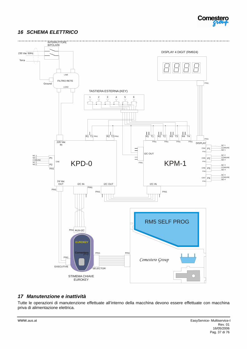
16 SCHEMA ELETTRICO
Comestero Group
RM5 SELF PROG
PIN1 PIN1
PIN1
PIN1
EXECUTIVESELECTOR
PIN1
1 2 3 4 5 6
INTERRUTTOREBIPOLARE
230 Vac 50Hz
FILTRO RETE
LINE
LOAD
PIN1PIN1
KPD-0
PIN1
PIN1PIN1
I2C IN I2C OUT24 VacOUT
R2 T2R1 T1
220 VacIN
P1
P2
PIN1
DISPLAY
KPM-1
PIN1
PIN1
I2C OUT
I2C IN
R4 T4R3 T3R2 T2R1 T1
PIN1 PIN1 PIN1 PIN1
P1
P2
P3
P4
CN4
CN5
CN6
CN7
CN6COMUNENC 2NO 2
NO 1NC 1
NC 1
COMUNE
COMUNE
COMUNE
COMUNE
PIN1
NO 4
NO 2
NO 1
NO 3
PIN1
PIN1
PIN1
PIN1
NC 2
NC 3
NC 4
TASTIERA ESTERNA (KEY)
DISPLAY 4 DIGIT (RM924)
STIMEMA CHIAVEEUROKEY
Terra
Ground
17 Manutenzione e inattività Tutte le operazioni di manutenzione effettuate all’interno della macchina devono essere effettuate con macchina priva di alimentazione elettrica.
alfred
A.u.S.Spielgeräte GmbH
alfred
Rechteck
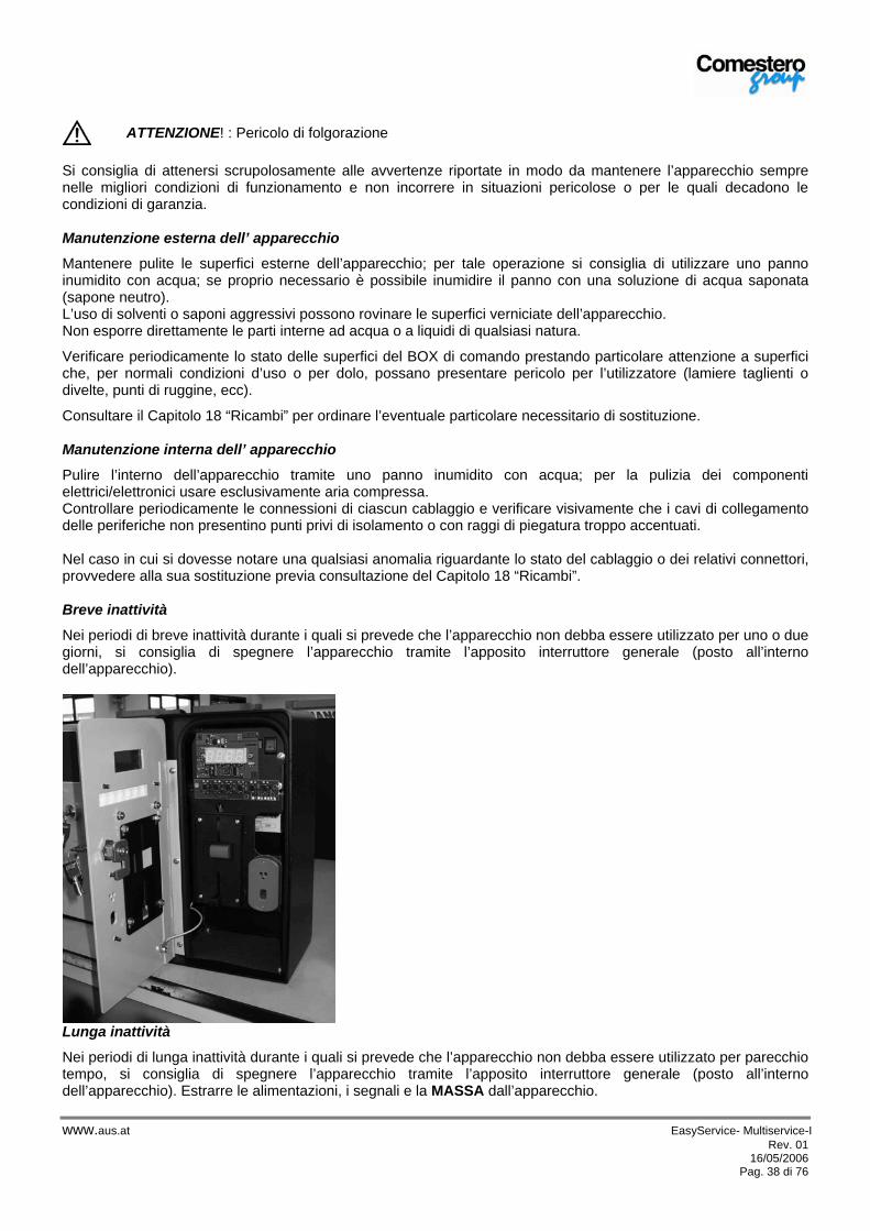
www.aus.at EasyService- Multiservice-I Rev. 01 16/05/2006
Pag. 38 di 76
Si consiglia di attenersi scrupolosamente alle avvertenze riportate in modo da mantenere l’apparecchio sempre nelle migliori condizioni di funzionamento e non incorrere in situazioni pericolose o per le quali decadono le condizioni di garanzia. Manutenzione esterna dell’ apparecchio
Mantenere pulite le superfici esterne dell’apparecchio; per tale operazione si consiglia di utilizzare uno panno inumidito con acqua; se proprio necessario è possibile inumidire il panno con una soluzione di acqua saponata (sapone neutro). L’uso di solventi o saponi aggressivi possono rovinare le superfici verniciate dell’apparecchio. Non esporre direttamente le parti interne ad acqua o a liquidi di qualsiasi natura.
Verificare periodicamente lo stato delle superfici del BOX di comando prestando particolare attenzione a superfici che, per normali condizioni d’uso o per dolo, possano presentare pericolo per l’utilizzatore (lamiere taglienti o divelte, punti di ruggine, ecc).
Consultare il Capitolo 18 “Ricambi” per ordinare l’eventuale particolare necessitario di sostituzione. Manutenzione interna dell’ apparecchio
Pulire l’interno dell’apparecchio tramite uno panno inumidito con acqua; per la pulizia dei componenti elettrici/elettronici usare esclusivamente aria compressa. Controllare periodicamente le connessioni di ciascun cablaggio e verificare visivamente che i cavi di collegamento delle periferiche non presentino punti privi di isolamento o con raggi di piegatura troppo accentuati. Nel caso in cui si dovesse notare una qualsiasi anomalia riguardante lo stato del cablaggio o dei relativi connettori, provvedere alla sua sostituzione previa consultazione del Capitolo 18 “Ricambi”. Breve inattività
Nei periodi di breve inattività durante i quali si prevede che l’apparecchio non debba essere utilizzato per uno o due giorni, si consiglia di spegnere l’apparecchio tramite l’apposito interruttore generale (posto all’interno dell’apparecchio).
Lunga inattività
Nei periodi di lunga inattività durante i quali si prevede che l’apparecchio non debba essere utilizzato per parecchio tempo, si consiglia di spegnere l’apparecchio tramite l’apposito interruttore generale (posto all’interno dell’apparecchio). Estrarre le alimentazioni, i segnali e la MASSA dall’apparecchio.
ATTENZIONE! : Pericolo di folgorazione
alfred
A.u.S.Spielgeräte GmbH

www.aus.at EasyService- Multiservice-I Rev. 01 16/05/2006
Pag. 39 di 76
Asportare dalla parete il BOX.
Proteggere il cambiamonete dalla polvere con l’imballo originale.
Per preservare l’apparecchio riporlo in luoghi asciutti e ben arieggiati.
18 Ricambi Di seguito sono riportati i disegni con i ricambi che A.u.S. Spielgeraet GmbH mette a disposizione per i propri clienti. Per ordinare un ricambio ricercare il codice ordine in una delle quattro tavole sotto riportate e comunicarlo al proprio addetto alle vendite o all’addetto del servizio assistenza A.u.S. Spielgeraet GmbH congiuntamente al numerodi matricola della macchina riportato sulla targa di identificazione (si veda paragrafo 5.3 “Identificazione apparecchiatura).
BOX CODICE D’ORDINE DESCRIZIONE QUANTITA’EASY / MULTI c20---10999-x Porta 1 EASY / MULTI z/EX-S30120 Serratura porta 1 EASY / MULTI c20---10993 Gancio serratura, paletto di chiusura 1
EASY SERVICE c27-23955 Serigrafia frontale 1 EASY / MULTI cp33-I30913 Interruttore bipolare luminoso 1 EASY / MULTI c20---11000-A Armadietto 1 EASY / MULTI c11-1011-20 Guarnizione porta 1
EASY SERVICE fSE-ATM-0-1-ES Scheda elettronica ATM per Easy Service 220V: Scheda elettronica timer per attivazione servizio.
1
EASY SERVICE fSE-924-2-TIM Display RM924 per Box Easy Temporizzato 1 EASY SERVICE c4-22-10974 Cavo Switch Gettoniera Meccanica 1 EASY SERVICE c4-22-10979 Cavo Filtro rete interruttore alimentazione 1 EASY / MULTI c4-22-10984 Cavo terra armadio – porta - basculante 1
MULTI 2 SERVIZI c27-23958 Serigrafia frontale con due pulsanti 1 MULTI z/ES-FILTRO Filtro rete 1
MULTI 2 SERVIZI fSE---KPA-220 Scheda alimentazione in 230Vac out 24Vac 1 MULTI 2 SERVIZI fSE---924-2-PAR Display RM924 per Box Multi 2 prezzi 1 MULTI 2 SERVIZI c4-22-10977 Cavo RM5T- Display 1
EASY / MULTI c4-22-10983 Cavo Filtro rete scheda KPD 1 MULTI 2 SERVIZI c4-22-10977 Cavo RM5T- Display 1
EASY / MULTI c4-22-10985 Cavo centrale di Terra 1 EASY / MULTI c4-22-10988 Cavo filtro rete interruttore 1
MULTI 2 SERVIZI c4-22-10976 Cavo alimentazione RM5T 1 MULTI 2 SERVIZI c4-T-OUT500 Cavo contatti relè lunghezza 5 mt 1 MULTI 6 SERVIZI fSE-924-2-DIS Display RM924 per Box Multi 6 prezzi 1 MULTI 6 SERVIZI fSE---KPD Display RM924 per Box Multi 6 prezzi 1 MULTI 6 SERVIZI fSE---KPM Display RM924 per Box Multi 6 prezzi 1 MULTI 6 SERVIZI fEK-CM-MP Display RM924 per Box Multi 6 prezzi 1 MULTI 6 SERVIZI fSE-924-2-DIS Display RM924 per Box Multi 6 prezzi 1 MULTI 6 SERVIZI c4-22-10980 Cavo I2C Bus 1 MULTI 6 SERVIZI c4-22-10981 Cavo alimentazione EK 1 MULTI 6 SERVIZI c4-22-10982 Cavo Display 1 MULTI 6 SERVIZI c4-22-10986 Cablaggio prezzi KPM 1 MULTI 6 SERVIZI c4-22-10987 Cavo connessione KPD - KPM 1 MULTI 6 SERVIZI c4-22-10989 Cavo RM5 1
N.B. sostituire “x” con la revisione del pezzo, verificare con l’assistenza telefonica della A.u.S. Spielgeratela versione con il numero di Serie della macchina a portata di mano.
ATTENZIONE! : Pericolo di folgorazione
alfred
A.u.S.Spielgeräte GmbH

www.aus.at EasyService- Multiservice-I Rev. 01 16/05/2006
Pag. 40 di 76
Sia per motivi di sicurezza, che per preservare l’integrità dell’apparecchiatura è indispensabile che qualsiasi operazione di manutenzione straordinaria (sostituzione di uno o più componenti) venga eseguita da un tecnico qualificato.
Ai fini di conservare diritto alla garanzia del particolare, dell’intero apparecchio o di altre sue parti, tutte le operazioni di manutenzione straordinaria devono essere svolte da personale autorizzato da A.u.S. Spielgeraete GmbH.
19 Smaltimento del prodotto L’eventuale smaltimento del prodotto deve essere fatto nel pieno rispetto delle norme in vigore. Separare i materiali di imballaggio (carta/plastica) e smaltirli separatamente dal prodotto nelle apposite discariche autorizzate.
alfred
A.u.S.Spielgeräte GmbH

www.aus.at EasyService- Multiservice-UK Rev. 01 16/05/2006
Page 41 of 76
20 Introduction This manual and its annexes provide all information required for installation and about the components of the product, the use and operation of the machine, as well as a technical introduction for a correct maintenance and appropriate use of the product. The information contained in this manual will be subject to modifications without notice and will not be binding for A.u.S. Spielgerate GmbH. Any care has been used to collect and to control the documentation included herein; however A.u.S. Spielgeratewill not be responsible for any use thereof. The same will also apply to any individual or company involved in the creation and production of this manual. Unless otherwise specified, any reference to companies, names, data and addresses used in the examples is absolutely fortuitous, having the only purpose of illustrating the use of the A.u.S. Spielgerate GmbH product. It is absolutely forbidden to reproduce any section hereof, in any form, if not expressly authorized by A.u.S. Spielgerate
20.1 General Description The EasyService and MultiService activation systems are the ideal solution to automate from the outside the payment and the activation of any time service; several models are available , capable of piloting up to 6 different services. They are particularly suitable for the automation of pre-existing manual devices and to be situated outside. They are waterproof and particularly resistant, the degree of protection of the device, at the issuing date of this manual, is “IP35”, only if it is applied as prescribed, to resist to atmospheric agents and vandalism. The models are different by configuration and are listed below:
G. EasyService 230Vac: control box with mono service coin mechanism H. EasyService 24Vac/dc: control box with mono service mechanical coin mechanism. I. MultiService 2 Prices 230Vac: control box with electronic coin mechanism – manages up to two services. J. MultiService 2 Prices 24Vac/dc: control box with electronic coin mechanism – manages up to two services. K. MultiService 6 Prices 230Vac: control box with electronic coin mechanism – manages up to six services. L. MultiService 6 Prices 24Vac/dc: control box with electronic coin mechanism – manages up to six services.
21 Warnings Carefully READ this manual before start up. The knowledge of the information and provisions container in this manual is essential for a correct use of the product. Upon receipt, make sure that the packaging and the product have not been damaged during transport. Pay attention to electric connection. No guarantee will be applied to any failure caused by the non compliance with any warning mentioned herein.
CAUTION!
IMPORTANT WARNING
Carefully READ this manual before start up.
alfred
A.u.S.Spielgeräte GmbH

www.aus.at EasyService- Multiservice-UK Rev. 01 16/05/2006
Page 42 of 76
22 Declaration of conformity
EC DECLARATION OF CONFORMITY
No.: 30-1029 The undersigned, representing the following manufacturer
Manufacturer:
Address: Or representing the mandatory authorized by the manufacturer within the European Community (or the European Economic area), referred to as follows (if applicable)
Authorized representative:
Address: Hereby declares that the following product
Product identification: Easy/Multi Service control box Is compliant with the prescriptions of the following European directives:
Reference no. Title
98/37/EC New machinery directive
And that all the following regulations and/or specifications have been applied Last two figures of the year in which the EC marking has been applied 05 Gessate, / / _____________________
(Signature) (name and function of the person in charge of signing on behalf of the manufacturer or his authorized representative)
alfred
A.u.S.Spielgeräte GmbH

www.aus.at EasyService- Multiservice-UK Rev. 01 16/05/2006
Page 43 of 76
EC DECLARATION OF CONFORMITY
No.: 30-1029 Reference to the regulations and / or technical specifications, or part thereof, used for this declaration of conformity ♦ Harmonized norms:
Reference no. Modification Title Parts
CEI 23-48 First+EC1 Casings for devices to fix electrical devices for domestic or similar use
CEI EN 55014-1 Fourth Electromagnetic compatibility for household appliances, electric tools and similar devices
CEI EN 60073 Fifth Fundamental principles and safety rules for human-machine interfacing, marking and identification
CEI EN 60446 Second Fundamental principles and safety rules for human-machine interfacing
CEI EN 60529 Second Casing protection level (IP code)
CEI EN 60555-1 First Disturbances in supply networks caused by devices
CEI EN 60664-1 First Insulation coordination for low voltage devices - Principles
CEI EN 60664-5 First Insulation coordination for low voltage devices – distance identification
CEI EN 60669-1 Fourth Non automatic control devices for fixed electric equipment for domestic or similar use
CEI EN 60947-1 Third Low voltage devices – General rules
CEI EN 61293 First Electric device marking – Safety prescriptions ♦ Other regulations or technical specifications
Reference no. Issue Title Parts
Other technical solutions, the details of which are included in the technical documentation or in the technical (manufacturing) file:
Other references or information required by the applicable European directives:
alfred
A.u.S.Spielgeräte GmbH
www.aus.at EasyService- Multiservice-UK Rev. 01 16/05/2006
Page 44 of 76
23 Guarantee Our change machines are guaranteed for a period of 12 months. The date and the serial number on the label shown below will apply. The label is placed inside the machine. The guarantee will not apply in the following cases:
Damage or breakage caused by transport. Damage or breakage caused by vandalism, natural disasters or malicious actions. Wrong installation or misinstallation of the product. Unsuitable or anomalous electric plants. Carelessness, negligence or incompetence in the use of the product. Non-compliance with the operating instructions. Interventions for presumed defects or convenient checks.
The interventions for repairs will be carried out in our Gessate laboratory where the parts will arrive free of expenses. No assistance intervention will be carried out by A.u.S. Spielgerate GmbH.at the customer’s premises unless further to previous agreement. For every piece of goods returned on repair account, a detailed description of the defect found out shall be attached. The parts will be returned carriage forward. At the expiry of the guarantee the assistance center will remain at your disposal. Furthermore the After-Sale Manager is at your complete disposal for any question you may have.
24 General notes
24.1 Checks upon the receipt of products Upon receipt of the product make sure that this has not been damaged during transport. If any damage of any kind should be noted, immediately make a complaint to the hauler. At the end of transport the packing shall be intact, i.e. it shall show:
No bruise, sign of crash, deformation or breakage of the container. No wet areas or signs that may mean that the container has been exposed to rain, freeze or heat. No tampering.
Make sure that the content of the container corresponds to the order.
24.2 Type of packaging The device is delivered tested and equipped as follows: - Closed door - Transparent bag placed on the upper side of the BOX, containing two copies of the machine key - Coin box - Tropicalized display - Tropicalized EuroKey key system - Transparent sack containing two female connectors FASTON type (4.8x0.8mm) The device is sent in a box with the following external dimensions (H 36 x W 26 x D 24.5 cm). Follow the instructions shown on the packing side.
alfred
A.u.S.Spielgeräte GmbH
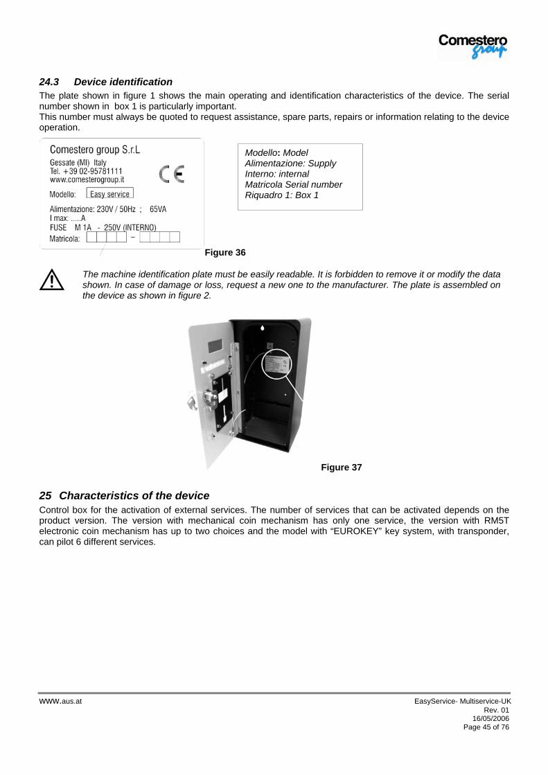
www.aus.at EasyService- Multiservice-UK Rev. 01 16/05/2006
Page 45 of 76
24.3 Device identification The plate shown in figure 1 shows the main operating and identification characteristics of the device. The serial number shown in box 1 is particularly important. This number must always be quoted to request assistance, spare parts, repairs or information relating to the device operation.
Figure 36
Figure 37
25 Characteristics of the device Control box for the activation of external services. The number of services that can be activated depends on the product version. The version with mechanical coin mechanism has only one service, the version with RM5T electronic coin mechanism has up to two choices and the model with “EUROKEY” key system, with transponder, can pilot 6 different services.
The machine identification plate must be easily readable. It is forbidden to remove it or modify the data shown. In case of damage or loss, request a new one to the manufacturer. The plate is assembled on the device as shown in figure 2.
Modello: Model Alimentazione: Supply Interno: internal Matricola Serial number Riquadro 1: Box 1
alfred
A.u.S.Spielgeräte GmbH
alfred
Rechteck
alfred
A.u.S.Spielgeräte GmbH

www.aus.at EasyService- Multiservice-UK Rev. 01 16/05/2006
Page 46 of 76
25.1 Overall dimensions The contacts towards the outside are of relay type; the specifications are shown in paragraph 8.3.
26 Risks deriving from using the device It is advisable to verify the device when it is open and only without power supply. Open the pivoting door (fig. 22 -23) only if the power supply has been previously cut directly by acting on the differential switch of the system. All the mobile parts, pivoting door and coin box, can cause injuries of different gravity if they are not properly handled. Risks due to electric energy: direct contacts during connection to the mains line- see “EN 61140” regulation – Protection from electric contacts – common system characteristics. Risks due to electric energy: for a correct installation of the system, make sure that the device complies with the safety provisions specified in “CEI 64-8/7” regulation –User electric systems…SPECIAL ENVIRONMENTS AND APPLICATIONS. Example:
EASY SERVICE MULTISERVICE 2 PRICES MULTISERVICE 6 PRICESMains version Low voltage Mains version Low voltage Mains
version Low voltage
INPUT VOLTAGE 230 Vac ± 10%
18÷28 Vdc ± 10% or
12÷18 Vac ± 10%
230 Vac ± 10%
12÷24 Vdc ± 10% or
12÷24 Vac ± 10%
230 Vac ± 10%
18÷34 Vdc ± 10% or
12÷24 Vac ± 10%
ABSORBED POWER 2W 16 W 40 W
OUTPUTS relay, current range 3A - 230Vdc relay, current range 2A - 30Vdc or 0,5A - 125Vac relay, current range 4A - 230Vdc
DIMENSIONS (173 X 331,5 X 164,25) mm
WEIGHT 8,5 Kg (with empty box)
COIN CAPACITY Approx. 400 (0,50€ or 1,00 €uro coins) – approx. 320 (€2,00 coins)
INSTALLED PERIPHERAL DEVICES
Mechanical coin mechanism (Optional)
RM5T electronic coin mechanism (Optional) RM5 F00
alfred
A.u.S.Spielgeräte GmbH
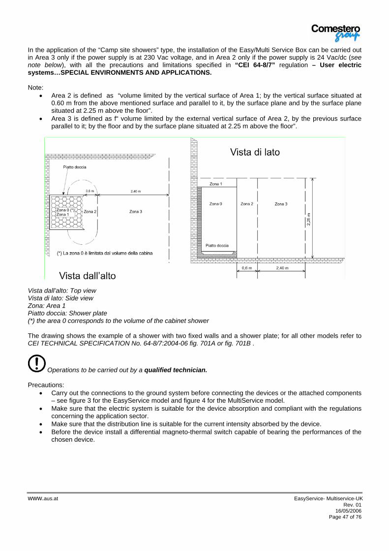
www.aus.at EasyService- Multiservice-UK Rev. 01 16/05/2006
Page 47 of 76
In the application of the “Camp site showers” type, the installation of the Easy/Multi Service Box can be carried out in Area 3 only if the power supply is at 230 Vac voltage, and in Area 2 only if the power supply is 24 Vac/dc (see note below), with all the precautions and limitations specified in “CEI 64-8/7” regulation – User electric systems…SPECIAL ENVIRONMENTS AND APPLICATIONS. Note:
• Area 2 is defined as “volume limited by the vertical surface of Area 1; by the vertical surface situated at 0.60 m from the above mentioned surface and parallel to it, by the surface plane and by the surface plane situated at 2.25 m above the floor”.
• Area 3 is defined as f“ volume limited by the external vertical surface of Area 2, by the previous surface parallel to it; by the floor and by the surface plane situated at 2.25 m above the floor”.
Vista dall’alto: Top view Vista di lato: Side view Zona: Area 1 Piatto doccia: Shower plate (*) the area 0 corresponds to the volume of the cabinet shower The drawing shows the example of a shower with two fixed walls and a shower plate; for all other models refer to CEI TECHNICAL SPECIFICATION No. 64-8/7:2004-06 fig. 701A or fig. 701B .
Operations to be carried out by a qualified technician. Precautions:
• Carry out the connections to the ground system before connecting the devices or the attached components – see figure 3 for the EasyService model and figure 4 for the MultiService model.
• Make sure that the electric system is suitable for the device absorption and compliant with the regulations concerning the application sector.
• Make sure that the distribution line is suitable for the current intensity absorbed by the device. • Before the device install a differential magneto-thermal switch capable of bearing the performances of the
chosen device.
alfred
A.u.S.Spielgeräte GmbH
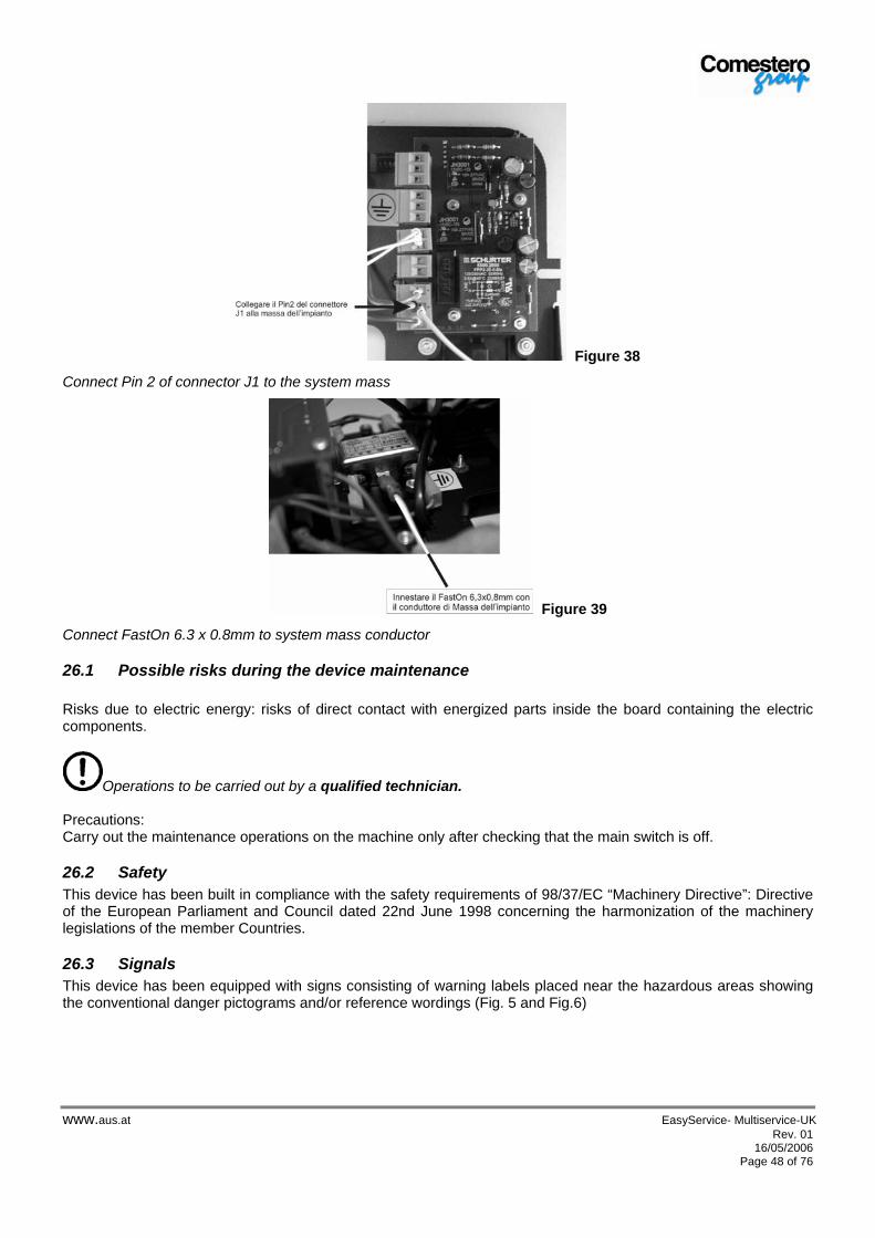
www.aus.at EasyService- Multiservice-UK Rev. 01 16/05/2006
Page 48 of 76
Figure 38
Connect Pin 2 of connector J1 to the system mass
Figure 39
Connect FastOn 6.3 x 0.8mm to system mass conductor
26.1 Possible risks during the device maintenance Risks due to electric energy: risks of direct contact with energized parts inside the board containing the electric components.
Operations to be carried out by a qualified technician. Precautions: Carry out the maintenance operations on the machine only after checking that the main switch is off.
26.2 Safety This device has been built in compliance with the safety requirements of 98/37/EC “Machinery Directive”: Directive of the European Parliament and Council dated 22nd June 1998 concerning the harmonization of the machinery legislations of the member Countries.
26.3 Signals This device has been equipped with signs consisting of warning labels placed near the hazardous areas showing the conventional danger pictograms and/or reference wordings (Fig. 5 and Fig.6)
alfred
A.u.S.Spielgeräte GmbH
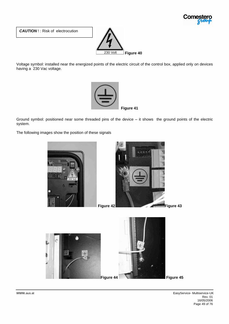
www.aus.at EasyService- Multiservice-UK Rev. 01 16/05/2006
Page 49 of 76
Figure 40
Voltage symbol: installed near the energized points of the electric circuit of the control box, applied only on devices having a 230 Vac voltage.
Figure 41
Ground symbol: positioned near some threaded pins of the device – it shows the ground points of the electric system. The following images show the position of these signals
Figure 42 Figure 43
Figure 44 Figure 45
CAUTION ! : Risk of electrocution
alfred
A.u.S.Spielgeräte GmbH

www.aus.at EasyService- Multiservice-UK Rev. 01 16/05/2006
Page 50 of 76
Figure 46
27 Handling and positioning The weight of the device makes it quite easy to transport it without requiring any type of mechanical support. In any case it is advisable to pay the UTMOST ATTENTION during transportation, in order to prevent the machine from falling and damaging.
28 Installation For wall installation: See figure drilling 12. Use screws having a max. diameter of 4 mm. Make sure that the application wall is free from bumps.
Figure 12
Wall drilling: front view
28.1 Devices with 230 Vac mains power supply For the electric connection: Before the device, install a differential magneto-thermal switch capable of bearing the performance of the chosen device , having a nominal differential current not higher than 30mA. The Easy/Multi Service box complies with all provisions specified in “CEI EN 60529- Protection level of casings” regulation, concerning the IP35 protection level, for which the compliance is declared. To obtain the abovementioned protection level the device must have a “WALL” installation. In order to avoid modifying the protection level of the device the gaskets inside the door and in the rear section must not be removed. For the passage of the power supply and control cables, it is necessary to re-install, at the end of the installation operations, the rear gasket in its original position.
alfred
A.u.S.Spielgeräte GmbH
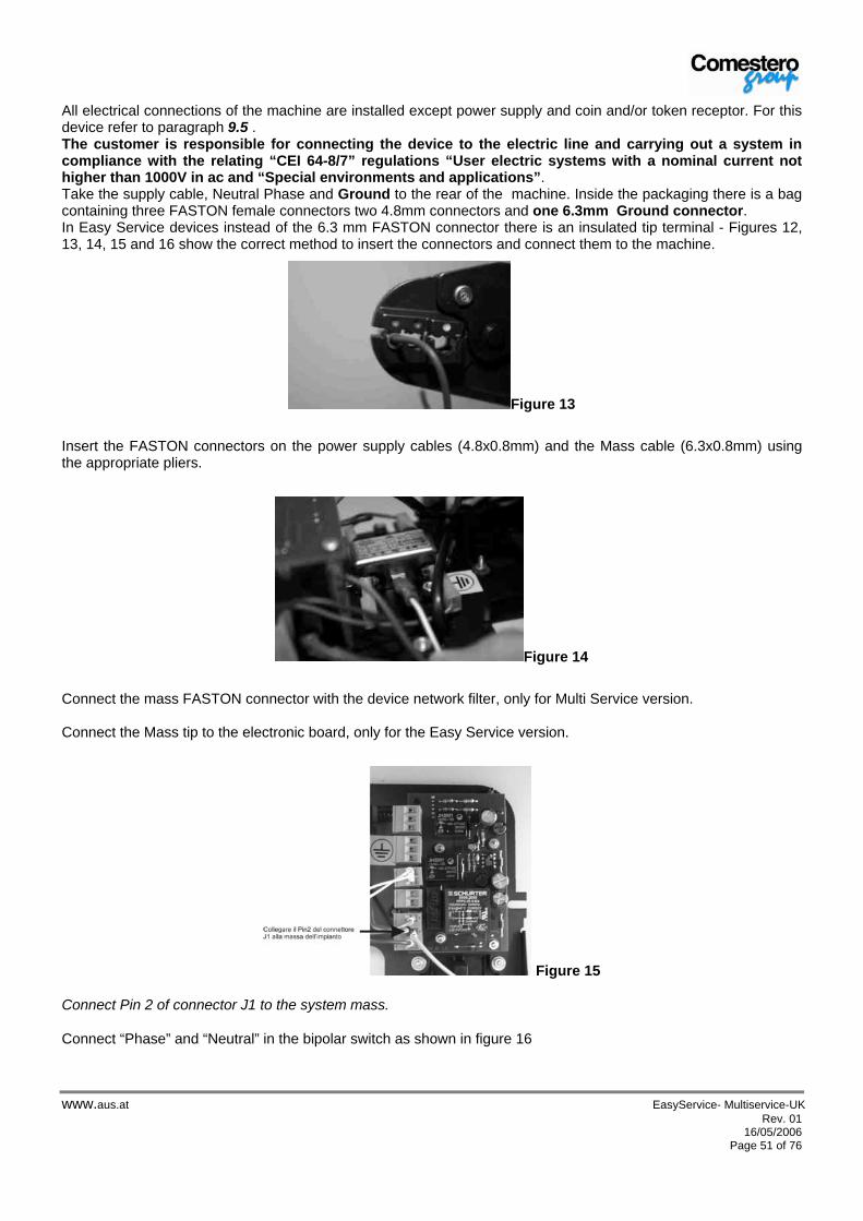
www.aus.at EasyService- Multiservice-UK Rev. 01 16/05/2006
Page 51 of 76
All electrical connections of the machine are installed except power supply and coin and/or token receptor. For this device refer to paragraph 9.5 . The customer is responsible for connecting the device to the electric line and carrying out a system in compliance with the relating “CEI 64-8/7” regulations “User electric systems with a nominal current not higher than 1000V in ac and “Special environments and applications”. Take the supply cable, Neutral Phase and Ground to the rear of the machine. Inside the packaging there is a bag containing three FASTON female connectors two 4.8mm connectors and one 6.3mm Ground connector. In Easy Service devices instead of the 6.3 mm FASTON connector there is an insulated tip terminal - Figures 12, 13, 14, 15 and 16 show the correct method to insert the connectors and connect them to the machine.
Figure 13
Insert the FASTON connectors on the power supply cables (4.8x0.8mm) and the Mass cable (6.3x0.8mm) using the appropriate pliers.
Figure 14
Connect the mass FASTON connector with the device network filter, only for Multi Service version. Connect the Mass tip to the electronic board, only for the Easy Service version.
Figure 15
Connect Pin 2 of connector J1 to the system mass.
Connect “Phase” and “Neutral” in the bipolar switch as shown in figure 16
alfred
A.u.S.Spielgeräte GmbH
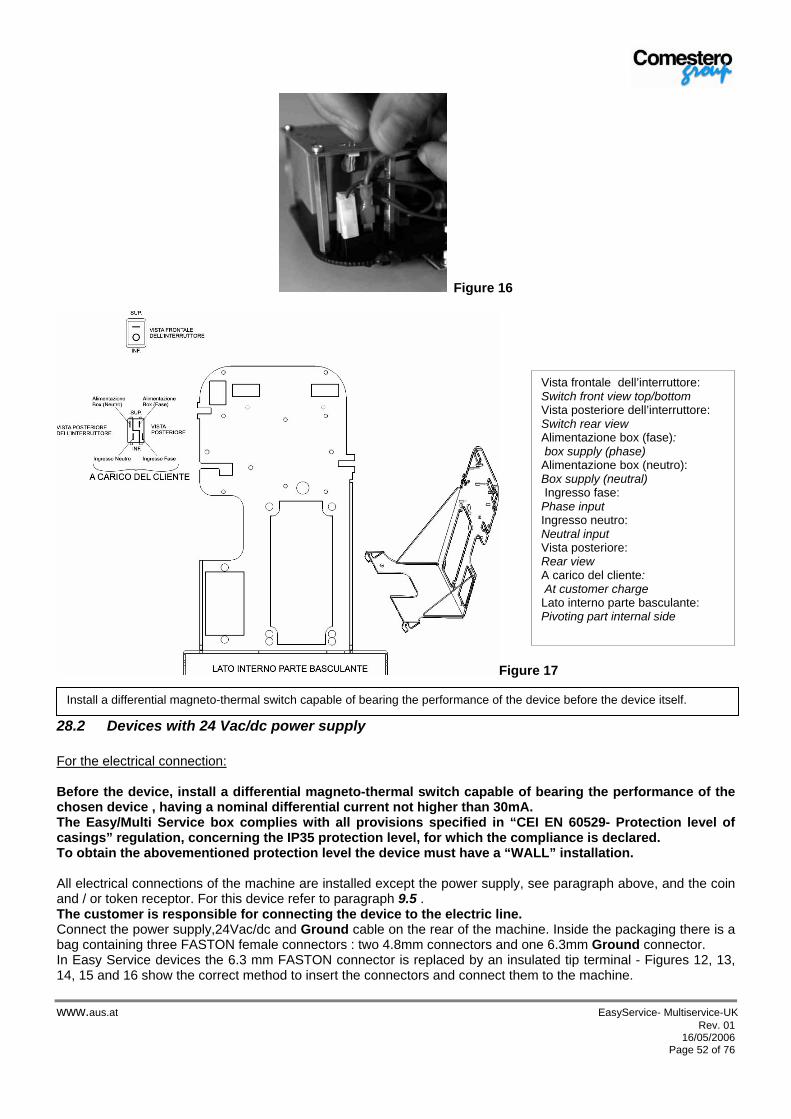
www.aus.at EasyService- Multiservice-UK Rev. 01 16/05/2006
Page 52 of 76
Figure 16
Figure 17
28.2 Devices with 24 Vac/dc power supply For the electrical connection: Before the device, install a differential magneto-thermal switch capable of bearing the performance of the chosen device , having a nominal differential current not higher than 30mA. The Easy/Multi Service box complies with all provisions specified in “CEI EN 60529- Protection level of casings” regulation, concerning the IP35 protection level, for which the compliance is declared. To obtain the abovementioned protection level the device must have a “WALL” installation. All electrical connections of the machine are installed except the power supply, see paragraph above, and the coin and / or token receptor. For this device refer to paragraph 9.5 . The customer is responsible for connecting the device to the electric line. Connect the power supply,24Vac/dc and Ground cable on the rear of the machine. Inside the packaging there is a bag containing three FASTON female connectors : two 4.8mm connectors and one 6.3mm Ground connector. In Easy Service devices the 6.3 mm FASTON connector is replaced by an insulated tip terminal - Figures 12, 13, 14, 15 and 16 show the correct method to insert the connectors and connect them to the machine.
Install a differential magneto-thermal switch capable of bearing the performance of the device before the device itself.
Vista frontale dell’interruttore: Switch front view top/bottom Vista posteriore dell’interruttore: Switch rear view Alimentazione box (fase): box supply (phase) Alimentazione box (neutro): Box supply (neutral) Ingresso fase: Phase input Ingresso neutro: Neutral input Vista posteriore: Rear view A carico del cliente: At customer charge Lato interno parte basculante: Pivoting part internal side
alfred
A.u.S.Spielgeräte GmbH

www.aus.at EasyService- Multiservice-UK Rev. 01 16/05/2006
Page 53 of 76
28.3 Connecting the service outputs For the connection of the service outputs refer to the summary table below.
Easy Service with mechanical coin
mechanism
2- Price Multi Service with electronic
coin mechanism 6 -Price Multiservice with electronic coin mechanism
and key system
Service relay output
J3
Inside the machine there is an ATM electronic board with female terminal connectors. Use connector J3 of ATM board (see fig. 18) as service output.
Service output no. 1
Inside the machine there is a wiring dedicated to the electronic coin mechanism outputs. The cable is headed with a 6 pole Molex connector, female contacts, code 43645-0600. Use contacts 1,2 and 3 of the cable (see fig. 19) for service no. 1.
Service outputs 1 to 4
Inside the device there is an electronic board called KPM with female terminal connectors. Use these connectors as follows: 1) CN1= Price 1 2) CN2= Price 2 3) CN3= Price 3 4) CN4= Price 4 (See figure 20)
Notice relay output
J6
Use connector J6 of ATM board (see fig.18) as notice output.
Service output no.2
Use contacts 4,5 and 6 of the wiring inserted on the electronic coin mechanism (see fig.19).
Service outputs 5 and 6
Inside the machine there is an electronic board named KPD with terminal female connectors. Use these connectors as follows: 1) CN5 = Price 5 2) CN6 = Price 6 (See figure 21)
Figure 18
alfred
A.u.S.Spielgeräte GmbH

www.aus.at EasyService- Multiservice-UK Rev. 01 16/05/2006
Page 54 of 76
Figure 19
Figure 20
Figure 21
28.4 Start up Before starting up the machine, verify that the electric line has been properly connected as described in paragraph “7”. Operations required for start up:
6) Close the pivoting part using the relevant fixing screws, see figure 22 7) Position the coin box in the lower part of the machine 8) Put the main switch of the device to position 1 9) Close the door 10) Power the machine from the electric panel
alfred
A.u.S.Spielgeräte GmbH

www.aus.at EasyService- Multiservice-UK Rev. 01 16/05/2006
Page 55 of 76
28.5 Assembly instructions for peripheral devices To assemble the peripheral devices read the instruction paper “Mechanical coin mechanism assembly procedure” or “ RM5T Electronic coin mechanism assembly procedure” specified below. N.B.: Before proceeding with the installation, a cross screwdriver is required. - Mechanical coin mechanism assembly -
3. Open EasyService door and loosen the two screws on the pivoting support (fig. 22). 4. Rotate the pivoting support towards the outside and then remove it by slightly lifting it and
reclining it towards its right side (fig. 23).
Figure 22 Figure 23
3. Apply the coin mechanism on the pivoting support (fig. 24).
Figure 24
alfred
A.u.S.Spielgeräte GmbH
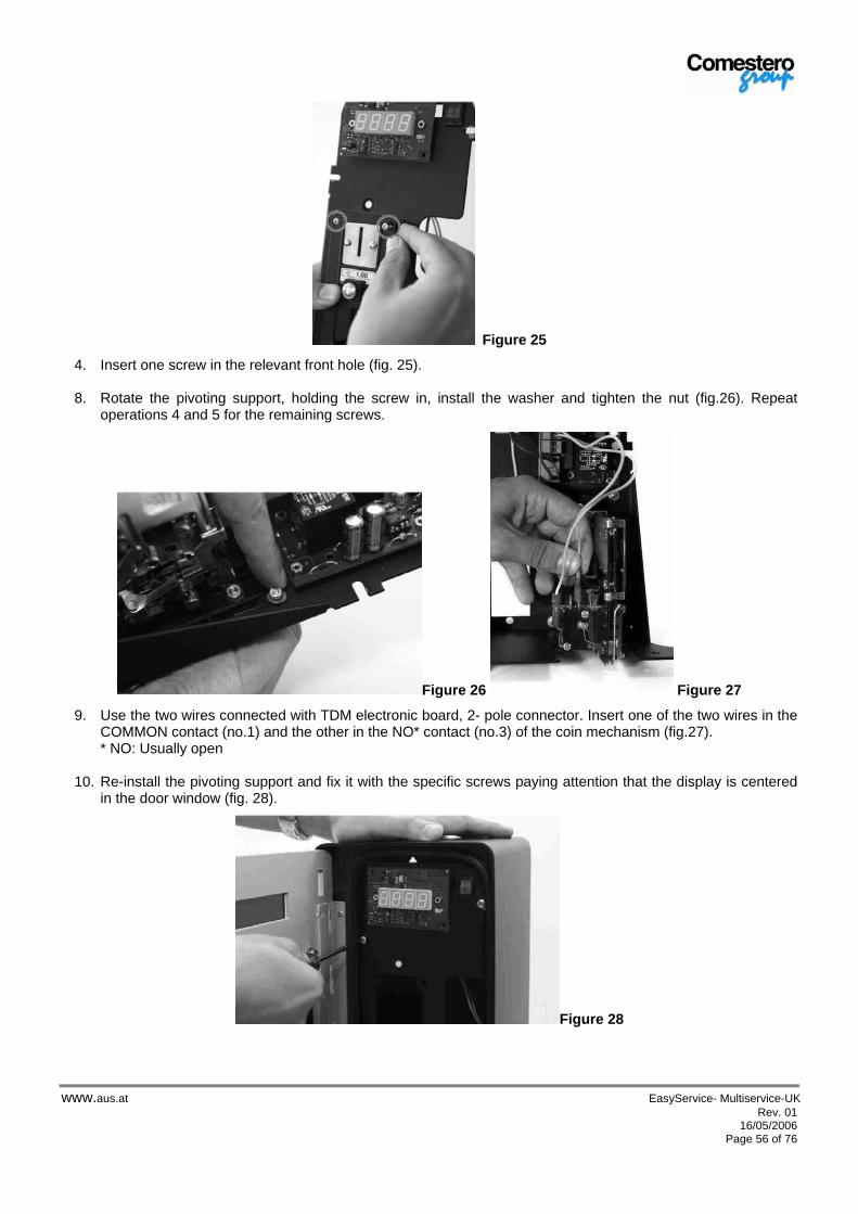
www.aus.at EasyService- Multiservice-UK Rev. 01 16/05/2006
Page 56 of 76
Figure 25
4. Insert one screw in the relevant front hole (fig. 25).
8. Rotate the pivoting support, holding the screw in, install the washer and tighten the nut (fig.26). Repeat operations 4 and 5 for the remaining screws.
Figure 26 Figure 27
9. Use the two wires connected with TDM electronic board, 2- pole connector. Insert one of the two wires in the COMMON contact (no.1) and the other in the NO* contact (no.3) of the coin mechanism (fig.27). * NO: Usually open
10. Re-install the pivoting support and fix it with the specific screws paying attention that the display is centered in the door window (fig. 28).
Figure 28
alfred
A.u.S.Spielgeräte GmbH
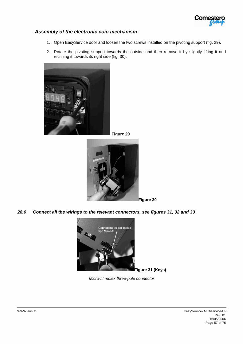
www.aus.at EasyService- Multiservice-UK Rev. 01 16/05/2006
Page 57 of 76
- Assembly of the electronic coin mechanism-
1. Open EasyService door and loosen the two screws installed on the pivoting support (fig. 29).
2. Rotate the pivoting support towards the outside and then remove it by slightly lifting it and reclining it towards its right side (fig. 30).
Figure 29
Figure 30
28.6 Connect all the wirings to the relevant connectors, see figures 31, 32 and 33
Figure 31 (Keys)
Micro-fit molex three-pole connector
alfred
A.u.S.Spielgeräte GmbH

www.aus.at EasyService- Multiservice-UK Rev. 01 16/05/2006
Page 58 of 76
Figure 32 (Supply)
Micro-fit molex two- pole connector
Figure 33 (Display)
51004 type molex four -pole connector
28.7 Apply the coin mechanism to the pivoting support (fig.34).
Figure 34
Make sure that the clip is properly inserted
28.8 Re-install the pivoting support and fix it using the relevant screws verifying that the display is centered in the door window (fig.28).
alfred
A.u.S.Spielgeräte GmbH

www.aus.at EasyService- Multiservice-UK Rev. 01 16/05/2006
Page 59 of 76
29 Operation and programming
29.1 Operation and programming with MECHANICAL COIN MECHANISM GENERAL NOTES The EASY SERVICE ,“with mechanical coin mechanism”, is a piloting box which is able to activate a timed service. This can be programmed for a value ranging from 1 second to 24 hours. It consists of a mechanical coin mechanism which is able to accept only one type of token/coin. Normal operation Under normal operating conditions, at rest, the machine display shows a zero on the last figure; this means that the machine is waiting for the introduction of a token/coin. When the coin is introduced, the machine shows a number on the display; this number represents the count of the coins which are being introduced, before reaching the service price. If this number is equal to the unit, the display will only show the service activation time. If the use of the START button has been programmed, when the token / coin is received the display will show the time but will not activate the service until the button is pressed. When the service is started, with both operating modes, if the START button (if present) is pressed the service will be temporarily interrupted until the button is pressed again and the service is re-started (Economizer). During the “Pause” phase, the time is not decremented. The board is equipped with a relay output for notice time. The notice relay is activated “x” seconds before the end of the service time. Time “x” can be configured up to 99 minutes and is disabled at the end of the service counting. The following time diagram shows this procedure.
CONTATTO GETTONIERA
RELE’ SERVIZIO
RELE’ PREAVVISO
T1
T2
T1 = 20mST2 = 94mS
29.1.1 General procedure for parameter setting This mode is used to program the operating parameters of the machine and the service time. On the first access to this mode, the different modifiable parameters show the default value. Then whenever the device is programmed, the previously programmed value is shown and it will be possible to confirm the same value by simply keeping the button pressed.
COIN MECHANISM CONTACT
SERVICE RELAY
NOTICE RELAY
alfred
A.u.S.Spielgeräte GmbH

www.aus.at EasyService- Multiservice-UK Rev. 01 16/05/2006
Page 60 of 76
The programmable parameters are as follows: • Counting time: hours, minutes, seconds. Minimum 1 second maximum 24 hours. • Notice time: minutes and seconds. Minimum 1 second maximum 99 minutes. • Number of coins to be introduced to reach the service value. • Setting of the operating mode of the coin mechanism contact: NO or NC (normally open, normally closed) • START button enabling To access the programming mode: 4. Switch the machine off 5. Using a pen top, keep pressed SW1 button positioned on the board front - see figure 35.
Figure 35
6. Switch the machine on again whilst pressing the button and keep the button pressed until the first parameter “H_00“ flashes. The waiting time should be approx. 6 seconds.
To modify the selected parameter value, press the button for a short time. Once the required value is reached, move to the next parameter to save the new data. To carry out this operation keep the key pressed for a long time and verify that the flash moves to the next parameter. The following is a programming example.
29.1.2 Service time programming DISPLAY BUTTON ACTION
“H_00“ (first figure flashes) Short button pressure Increases “H _01“ (first figure flashes) Short button pressure Increases “H _02“ (first figure flashes) Long button pressure Moves to the next parameter
“H _02“ (second figure flashes) Short button pressure Increases “H _12“ (second figure flashes) Short button pressure Increases “H _22“ (second figure flashes) Short button pressure Increases “H _22“ (second figure flashes) Long button pressure Moves to the next parameter
“n_00“ (first figure flashes) Short button pressure Increases “n_01“ (first figure flashes) Short button pressure Increases “n_02“ (first figure flashes) Long button pressure Moves to next parameter
“n_02“ (second figure flashes) Long button pressure Moves to next parameter
“S_00“ (second figure flashes) Short button pressure Increases “S_01“ (second figure flashes) Short button pressure Increases “S_02“ (second figure flashes) Short button pressure Increases “S_02“ (second figure flashes) Long button pressure Moves to next parameter
“S_12“ (first figure flashes) Short button pressure Increases “S_22“ (first figure flashes) Short button pressure Increases “S_32“ (first figure flashes) Long button pressure Moves to next parameter
Programming button
alfred
A.u.S.Spielgeräte GmbH
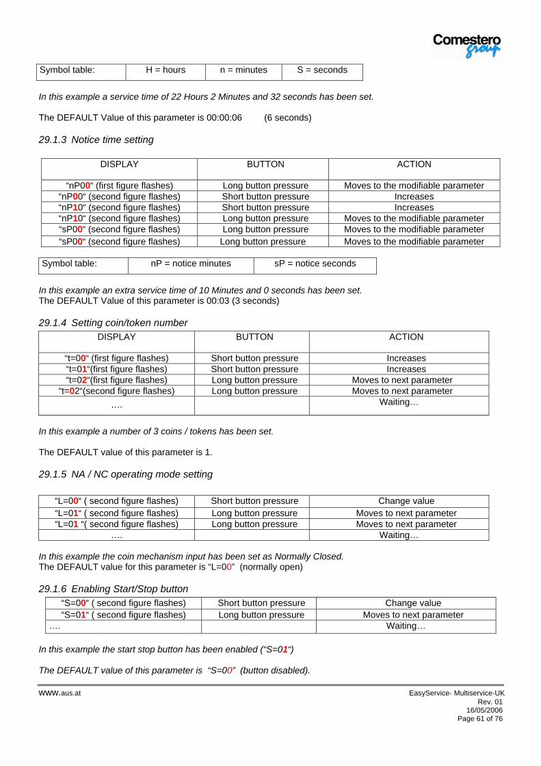
www.aus.at EasyService- Multiservice-UK Rev. 01 16/05/2006
Page 61 of 76
Symbol table: H = hours n = minutes S = seconds
In this example a service time of 22 Hours 2 Minutes and 32 seconds has been set. The DEFAULT Value of this parameter is 00:00:06 (6 seconds)
29.1.3 Notice time setting
DISPLAY
BUTTON
ACTION
“nP00“ (first figure flashes) Long button pressure Moves to the modifiable parameter “nP00“ (second figure flashes) Short button pressure Increases “nP10“ (second figure flashes) Short button pressure Increases “nP10“ (second figure flashes) Long button pressure Moves to the modifiable parameter “sP00“ (second figure flashes) Long button pressure Moves to the modifiable parameter “sP00“ (second figure flashes) Long button pressure Moves to the modifiable parameter
Symbol table: nP = notice minutes sP = notice seconds
In this example an extra service time of 10 Minutes and 0 seconds has been set. The DEFAULT Value of this parameter is 00:03 (3 seconds)
29.1.4 Setting coin/token number DISPLAY
BUTTON
ACTION
“t=00“ (first figure flashes) Short button pressure Increases “t=01“(first figure flashes) Short button pressure Increases “t=02“(first figure flashes) Long button pressure Moves to next parameter
“t=02“(second figure flashes) Long button pressure Moves to next parameter …. Waiting…
In this example a number of 3 coins / tokens has been set. The DEFAULT value of this parameter is 1.
29.1.5 NA / NC operating mode setting
“L=00“ ( second figure flashes) Short button pressure Change value “L=01“ ( second figure flashes) Long button pressure Moves to next parameter “L=01 “( second figure flashes) Long button pressure Moves to next parameter
…. Waiting… In this example the coin mechanism input has been set as Normally Closed. The DEFAULT value for this parameter is “L=00” (normally open)
29.1.6 Enabling Start/Stop button “S=00“ ( second figure flashes) Short button pressure Change value “S=01“ ( second figure flashes) Long button pressure Moves to next parameter
…. Waiting… In this example the start stop button has been enabled (“S=01“) The DEFAULT value of this parameter is “S=00” (button disabled).
alfred
A.u.S.Spielgeräte GmbH
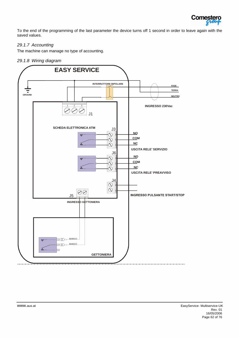
www.aus.at EasyService- Multiservice-UK Rev. 01 16/05/2006
Page 62 of 76
To the end of the programming of the last parameter the device turns off 1 second in order to leave again with the saved values.
29.1.7 Accounting The machine can manage no type of accounting.
29.1.8 Wiring diagram
NC
NO
COM
NC
NOCOM
SCHEDA ELETTRONICA ATM
GETTONIERA
INGRESSO GETTONIERA
INTERRUTTORE BIPOLARE
GROUND
FASE
NEUTRO
INGRESSO 230Vac
USCITA RELE’ SERVIZIO
USCITA RELE’ PREAVVISO
J1
J6
J3
J5
J4
EASY SERVICE
BIANCO
BIANCO
1
1
1
1
2
3
2
3
2
2 3
21
TERRA
alfred
A.u.S.Spielgeräte GmbH
www.aus.at EasyService- Multiservice-UK Rev. 01 16/05/2006
Page 63 of 76
29.2 Operation and programming with ELECTRONIC COIN MECHANISM GENERAL NOTES The TWO-SERVICE MULTISERVICE “with electronic coin mechanism” is a piloting device capable of enabling two or three timed services. It consists of an electronic coin mechanism able to accept different types of tokens and/or coins.
29.2.1 General characteristics The RM5T coin mechanism can be programmed (via Clone 5 program – see paragraph 12.9) to carry out the following functions:
Progressive timer: carries out the timing of a service proportionally to the accumulated credit.
Progressive timer with service request: carries out the timing of a service proportionally to the accumulated service, the service is activated via the key installed on the Box front.
Double progressive timer: carries out up to two different timings, the times of which are connected to the
accumulated credit. The activation is carried out via the two keys installed on the Box front. The following paragraphs explain in detail the three different operating modes.
29.2.2 Regular operation with Progressive Timer This recognizes 59 coins having even 59 different values, it sums them up and when a pre-set value is reached (basic service cost), it enables a signal for a set time (basic service time). If other coins are added the signal duration is increased proportionally to the value of the added coins. The coin mechanism manages a display which visualizes the introduced coins until the basic cost is reached and then it visualizes the time in seconds or in minutes. An output signal is provided to notify the expiry of the available time; this notice time is adjustable. Using the programming systems, it is possible to activate the notice output as Coin counter. The number of contact closures is equal to: Total amount introduced. Basic value There is also an input signal called economizer. This signal blocks the time and suspends the relating output command. When this signal is removed, the coin mechanism re-enables the service and the time counting.
alfred
A.u.S.Spielgeräte GmbH

www.aus.at EasyService- Multiservice-UK Rev. 01 16/05/2006
Page 64 of 76
29.2.2.1 Local programming for progressive Timer mode It is possible to set some of the coin mechanism parameters via the two keys and the display. To access the programming and set the values proceed as follows. When editing the figures the decimal point is used to show which figure is currently selected. Description Display Keys Coin mechanism off off enabled Coin mechanism activation enabled Input under configuration 3030 (flashes) enabled
disabled 1 (flashes)
Setting the first price figure 1.234 input 1 increases thousands input 2 moves to hundreds
Setting the second price figure 12.34 input 1 increases hundreds input 2 moves to tens
Setting the third price figure 123.4 input 1 increases tens input 2 moves to units
Setting the fourth price figure 1234. input 1 increases units input 2 moves to next field
2 (flashes)
Setting the first time figure 1.234 input 1 increases thousands input 2 moves to hundreds
Setting the second time figure 12.34 input 1 increases hundreds input 2 moves to tens
Setting the third time figure 123.4 input 1 increases tens input 2 moves to units
Setting the fourth time figure 1234. input 1 increases units input 2 moves to next field
3 (flashes)
Setting the first notice time figure 1.234 input 1 increases thousands input 2 moves to hundreds
Setting the second notice time figure 12.34 input 1 increases hundreds input 2 moves to tens
Setting the third notice time figure 123.4 input 1 increases tens input 2 moves to units
Setting the fourth notice time figure 1234. input 1 increases units input 2 moves to next field
9999 (flashes)
End of configuration Switch the coin mechanism off and switch it on again to enable the new settings
To enable the new settings it is necessary to cut and restore the coin mechanism power supply.
29.2.3 Regular operation of the progressive Timer with service request The only difference from the Progressive Timer model, paragraph 12.3, is that the timed signal is provided only when the customer requests it by pressing button (1) of the BOX.
29.2.3.1 Local Programming for progressive Timer mode with service request For programming refer to paragraph 10.2.2.1 .
alfred
A.u.S.Spielgeräte GmbH

www.aus.at EasyService- Multiservice-UK Rev. 01 16/05/2006
Page 65 of 76
29.2.4 Double progressive timer normal working Functional description Clone 5 side When it is used as a double progressive timer, the coin mechanism allows to purchase distribution times on two output lines. In other words the user introduces some coins (or tokens) the value of which is accumulated.
The distribution prices are set through the fields Price 1 / Time 1 for output 1 and Price 2 / Time 2 for output 2.
If both inputs are enabled and with no credit, the acceptance of new coins is inhibited. When one of the inputs is enabled the accumulated credit is converted into time and the output associated with the selected input remains active for the purchased time. If on the output there was already an ongoing timing, the new calculated time is added to the current time
To decide whether the activation of an input coincides with the closing or the opening of the relevant contact use the High activation field. If this field is enabled, the input is considered on when the contact is open.
It is possible to set the initial credit required to start the supply so that it is higher than the following increases to be converted into distribution time.
The field Minimum adding shows the adding following the distribution starting price. The minimum addition is common to both timers.
When one of the inputs is activated, for 5 seconds the display shows the countdown on the relating timer.
The coin mechanism can be configured so that it considers the input on when the contact is closed or when the contact is open.
If the High activation field is enabled, the input is considered on when the relevant contact is closed. The opposite occurs when the field is disabled
Times can be expressed in seconds or minutes. The countdown is displayed when the input is enabled and is shown in minutes or seconds depending on the settings. In any case the last minute of the timing is always shown in seconds.
The selection is be carried out via the Time in minutes field
The credit can be accumulated up to a maximum value equal to 220 times the basic price. Once this value is reached all new coins/tokens will be rejected.
The maximum time which can be accumulated is 65000 seconds.
It is possible to activate an anti-fraud function which, in case of fraud attempts, will stop the coin mechanism for a set time and then it will set the coin mechanism to zero deleting the accumulated credit and any current timing. When the coin mechanism is disabled any distribution is suspended and the coins rejected.
To enable this function it is necessary to enable the Inhib.field in the “Anti-fraud” section. The numeric field of the “Anti-fraud” section enables the setting of the time (in seconds) during which the coin mechanism remains blocked before it starts working again.
The following diagram shows an example of the operation of the double timer. The example shows the behaviour of Output 1 and Timer 1 according to the activity on Input 1, but the same considerations apply to Output2 / Timer 2 / Input 2. Accumulated credit/Input 1 /Timer 1/Output 1
Uscita 1
Timer 1
Ingresso 1
Credito accumulato
A B C
6. some credit is accumulated (shown on the accumulated credit diagram)
7. the impulse on Input 1 diagram shows the activation of the Input (indicated with A) and the credit is converted into time (we assume that the conversion originates no residual credit). Timer 1 diagram shows that the time has been uploaded and then it starts to run down.Together with the time uploading, Output 1 is enabled.
8. further credit is then introduced … 9. and the input is enabled again (impulse B).
Also in this case the credit is converted into time which is uploaded on the timer. Consequently the time associated to Timer 1 is increased by the result of the new Credit / Time conversion.
The time keeps going until it reaches 0. Consequently Output 1 is disabled.
alfred
A.u.S.Spielgeräte GmbH

www.aus.at EasyService- Multiservice-UK Rev. 01 16/05/2006
Page 66 of 76
29.2.4.1 Local programming for Double progressive timer mode It is possible to set some of the coin mechanism parameters via the two keys and the display. To use this function proceed as follows. The input column shows if these the inputs are enabled or not. This is because the inputs can be enabled when open or enabled when closed, depending on the setting of the operating polarity ( “High Activation” field in Clone5). When the figures are edited the decimal point is used to show which figure is currently selected. Description Display Inputs Coin mechanism off off enabled Coin mechanism start up enabled input being configured 3232 (flashes) enabled
disabled 1 (flashes)
setting first figure of price 1 1.234 input 1 increases thousands input 2 moves to hundreds
setting second figure of price 1 12.34 input 1 increases hundreds input 2 moves to tens
setting third figure of price 1 123.4 input 1 increases tens input 2 moves to units
setting fourth figure of price 1 1234. input 1 increases units input 2 moves to next field
2 (flashes)
Setting first figure of time 1 1.234 input 1 increases thousands input 2 moves to hundreds
Setting second figure of time 1 12.34 input 1 increases hundreds input 2 moves to tens
Setting third figure of time 1 123.4 input 1 increases tens input 2 moves to units
Setting fourth figure of time 1 1234. input 1 increases units input 2 moves to next field
3 (flashes)
Setting first figure of price 2 1.234 input 1 increases thousands input 2 moves to hundreds
Setting second figure of price 2 12.34 input 1 increases hundreds input 2 moves to tens
Setting third figure of price 2 123.4 input 1 increases tens input 2 moves to units
Setting fourth figure of price 2 1234. input 1 increases units input 2 moves to next field
4 (flashes) Setting first figure of time 2 1.234 input 1 increases thousands
input 2 moves to hundreds Setting second figure of time 2 12.34 input 1 increases hundreds
input 2 moves to tens Setting third figure of time 2 123.4 input 1 increases tens
input 2 moves to units Setting fourth figure of time 2 1234. input 1 increases units
input 2 moves to next field 9999 (flashes)
End of configuration Switch the coin mechanism off and restart it to enable the new settings
alfred
A.u.S.Spielgeräte GmbH

www.aus.at EasyService- Multiservice-UK Rev. 01 16/05/2006
Page 67 of 76
During programming the following checks must be carried out: if by increasing a figure the maximum allowed for the parameter during the setting phase is exceeded, the
figure will go to 0. For example, if the hundreds of a number with a value of 199 and a maximum of 200 are being set, then the
next value is 99.
The minimum increase value of a price is equal to the basic value. For this reason, if the basic value is 10 it is not possible to set the price units, but only the thousands, the hundreds and the tens.
The time settings are in minutes or seconds depending on the coin mechanism setting (“Service duration in sec/min” field in Clone5).
29.2.5 Programming with Clone 5 The following image shows the page of Clone 5 in case of selection of the progressive timer with double external activation, which sets the behaviour as double progressive timer.
The following table shows the purpose of the available settings. The list shows the name of the different fields and the relevant description.
Field Description RM5 T 30 – Tot. timer If enabled, this field allows to access the setting for the use of the coin
mechanism as a progressive timer 3R – External activation This field must be enabled to access the enabling of the double external reset Double external activation If enabled, this shows that the two coin mechanism inputs are used as
activation for the two timers High activation This allows to select the polarity of the inputs enabling the timers.
If this field is enabled the inputs are considered as active when the contact is open. Viceversa the field is not enabled. If the BOX keys are used, this field must not be selected.
Display off If this field is activated the display is no longer updated. Time in minutes If this field is activated the times are expressed (and displayed) in minutes,
otherwise they are processed as seconds.
Configuration
Anti-fraud This enables an anti-fraud system for the coin mechanism. If a fraud attempt is identified, the coin mechanism is blocked for the time set in the numeric editing field.
Price 1 As far as output 1 is concerned, it represents the amount necessary for a distribution having a duration shown in the field below.
Service duration in sec/min Distribution time corresponding to the price shown in the field above. In this case it applies to output 1
Price 2 As far as output 2 is concerned, it represents the amount necessary for a distribution having a duration shown in the field below.
Programming
Service duration in sec/min Distribution time corresponding to the price shown in the field above. In this case it applies to output 2
alfred
A.u.S.Spielgeräte GmbH
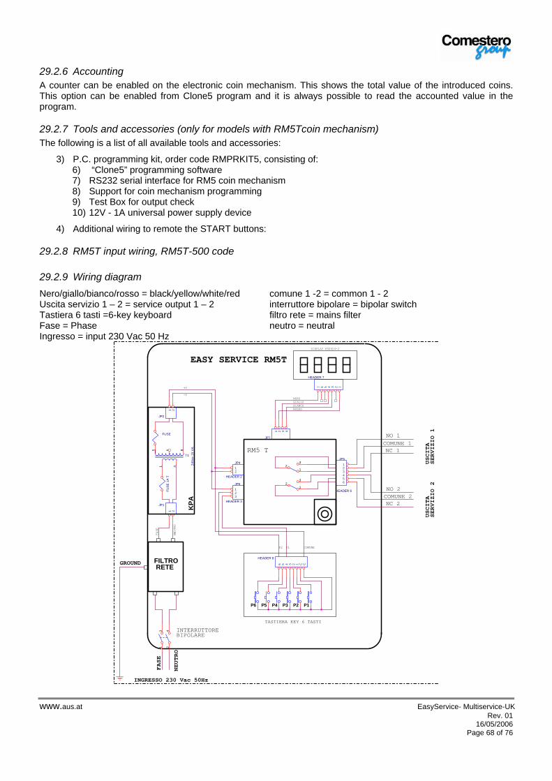
www.aus.at EasyService- Multiservice-UK Rev. 01 16/05/2006
Page 68 of 76
29.2.6 Accounting A counter can be enabled on the electronic coin mechanism. This shows the total value of the introduced coins. This option can be enabled from Clone5 program and it is always possible to read the accounted value in the program.
29.2.7 Tools and accessories (only for models with RM5Tcoin mechanism) The following is a list of all available tools and accessories:
3) P.C. programming kit, order code RMPRKIT5, consisting of: 6) “Clone5” programming software 7) RS232 serial interface for RM5 coin mechanism 8) Support for coin mechanism programming 9) Test Box for output check 10) 12V - 1A universal power supply device
4) Additional wiring to remote the START buttons:
29.2.8 RM5T input wiring, RM5T-500 code
29.2.9 Wiring diagram Nero/giallo/bianco/rosso = black/yellow/white/red comune 1 -2 = common 1 - 2 Uscita servizio 1 – 2 = service output 1 – 2 interruttore bipolare = bipolar switch Tastiera 6 tasti =6-key keyboard filtro rete = mains filter Fase = Phase neutro = neutral Ingresso = input 230 Vac 50 Hz
-V
P1
USCITA
SERVIZIO 2
JP5
HEADER 6
123456
DISPLAY fSE924-2
P1
T1
24Va
c 15
VA
1 4
5 6 8
HEADER 7
1234567
FUSE
P3
P2
JP1
1 2NEUTRO
P2
KPA
FASE
INGRESSO 230 Vac 50Hz
P4
COMUNE
NEUT
RO
P5
GROUND
TASTIERA KEY 6 TASTI
JP7
1 2 3 4
NO 1
JP6
HEADER 3
123
FILTRO RETE
21
3
NERO
COMUNE 1
HEADER 8
6 5 4 3 2 1 C C
JP2
1 2
13
24
P6
NC 1
EASY SERVICE RM5T
NC 2
JP4
HEADER 2
12
ROSSO
COMUNE 2
21
3
GIALLO
RM5 T
BIANCO
NO 2FUSE
1A
T
INTERRUTTOREBIPOLARE
FASE
+V
USCITA
SERVIZIO 1
alfred
A.u.S.Spielgeräte GmbH
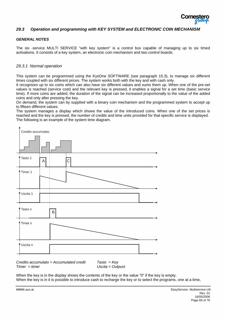
www.aus.at EasyService- Multiservice-UK Rev. 01 16/05/2006
Page 69 of 76
29.3 Operation and programming with KEY SYSTEM and ELECTRONIC COIN MECHANISM GENERAL NOTES The six -service MULTI SERVICE “with key system” is a control box capable of managing up to six timed activations. It consists of a key system, an electronic coin mechanism and two control boards.
29.3.1 Normal operation This system can be programmed using the KysOne SOFTWARE (see paragraph 15.3), to manage six different times coupled with six different prices. The system works both with the key and with cash only. It recognizes up to six coins which can also have six different values and sums them up. When one of the pre-set values is reached (service cost) and the relevant key is pressed, it enables a signal for a set time (basic service time). If more coins are added, the duration of the signal can be increased proportionally to the value of the added coins and only after pressing the key. On demand, the system can by supplied with a binary coin mechanism and the programmed system to accept up to fifteen different values. The system manages a display which shows the value of the introduced coins. When one of the set prices is reached and the key is pressed, the number of credits and time units provided for that specific service is displayed. The following is an example of the system time diagram.
Uscita 1
Timer 1
Tasto 1A C
Credito accumulato
Uscita n
Tasto nB
Credito accumulato = Accumulated credit Tasto = Key Timer = timer Uscita = Outpust When the key is in the display shows the contents of the key or the value “0” if the key is empty. When the key is in it is possible to introduce cash to recharge the key or to select the programs, one at a time,
alfred
A.u.S.Spielgeräte GmbH

www.aus.at EasyService- Multiservice-UK Rev. 01 16/05/2006
Page 70 of 76
If in the machine there is not enough credit or no credit at all, when one of the keys is pressed the corresponding service cost is shown for a few seconds.
29.3.2 System programming and configuration The following image shows the main page of “KysOne”program.
Pulsante perimpostare i tempi
Pulsante per impostare i prezzi
Gestione della MancataVendita
Sistema Audit“Contabilità”
Gestione Venditain Contanti
Valore Massimocaricabile in chiave
The following table shows the main functions available on the key: Configuration items Description Codes It is possible and advisable to set the identification codes. These codes are Manager, Location and Machine. Single cash sale When cash is introduced for a level higher than the service level and the service is selected, the change is removed and
counted in a dedicated counter. Multiple cash sale When cash is introduced for a level higher than the service level and the service is selected, the change is made
available with no time limit. Timed multiple cash sale When cash is introduced for a level higher than the service level and the service is selected, the change is made
available for a time set in seconds, after which the credit is removed and counted. Failed sale management - credit preserved
When a sale is not successful the credit is returned and shown on the display
Failed sale management – Failed sale
When a sale is not successful the credit is removed and counted in a dedicated counter
Recharge key It is possible to activate and manage a recharge key. This key, with a pre-set value leaves, each time that it is used, on the system, a set value (e.g. 5 €). The final user can load this value on his own key by introducing it in the system.
Configuration key It is possible to activate and manage a Configuration key. This key allows to modify, if necessary, the system values without requiring the PC on the site where the device is installed.
Programming items Description Prices It is possible to set up to 6 prices of an equal or different value, associated to set times – see line below.
Times It is possible to set up to 6 times of an equal or different value, associated to set prices – see line above.
pulsante per impostare i prezzi button to set prices sistema audit "Contabilita" "Accounting" audit system pulsante per impostare i tempi button to set times Valore massimo caricabile in chiave Max. value to be charged on key Gestione vendita in contanti Cash sale management Gestione mancata vendita Failed sale management
alfred
A.u.S.Spielgeräte GmbH

www.aus.at EasyService- Multiservice-UK Rev. 01 16/05/2006
Page 71 of 76
29.3.3 Local programming of the coin mechanism The SELF-PROG function is very useful when a coin or a token must be programmed directly on the machines where the coin mechanisms have been installed, since the first six channels of the RM5 coin mechanism can be re-programmed without requiring any external device. Please remember that besides the programming of the coin / token on the specific channel, it may be necessary to modify other parameters of the coin mechanism such as, for example, value assignment. In this case it is absolutely necessary to use either the Portable calibrator or the PC Kit. Programming the token or the coin on channel 6
• With machine off put the 6 coin mechanism DIP-SWITCHes to ON
• Energize and introduce 15 coins / tokens.
• Wait for the double “clack” signalling end of programming
• Put the DIP switches to OFF
• Switch the coin mechanism off and switch it on again Programming coins / tokens on channels 1 to 5
• With machine off put the 6 coin mechanism DIP-SWITCHes to ON • Energize and introduce 1 or 2 coins. • Only the SWITCH corresponding to the channel to be programmed must be left to ON • Introduce coins up to the double “clack” signalling end of programming • Put the DIP switches to OFF
• Switch the coin mechanism off and switch it on again NOTE: At the end of the procedure the first two which have been introduced may be rejected
With this operation the new calibration (coin / token) will maintain the previously programmed value. Check that the position of the channel where the new calibration has been carried out is compatible with the value table of the Key System.
29.3.3.1 Portable calibrator for coin mechanism (optional) In addition to the possibility to modify all coin mechanism functions, it also includes the “CLONING” function. This function allows to take data from a coin mechanism or from a PC and to transfer them to another coin mechanism, thus making the second one identical to the first, configuration and options included.
29.3.4 Accounting On the key system there are several accounting menus. Accounting is always on. The system is able to keep the following readings:
• Number of coins introduced per type of coin • Total number of coins introduced • Number of sales carried out per sale price • Total number of sales carried out • Total value loaded onto keys • Total value downloaded from keys • Total value of the bonuses, if enabled • Total number of free sales, if enabled • Total Discount applied in the “Happy hours” time zones , if enabled • …
alfred
A.u.S.Spielgeräte GmbH

www.aus.at EasyService- Multiservice-UK Rev. 01 16/05/2006
Page 72 of 76
The tool to read the machine accounting is the “KysOne” program. The following is an example of accounting reading carried out on one system.
Coins introduced
Key System total accounting
In cases of several applications, it is possible to request an additional tool, the “Audit Box”. Please refer to the chapter “Accessories” below.
29.3.5 Tools and accessories The following is a list of all available tools and accessories: a) P.C. programming kit, for the key system, order code CL-SOFTWARE
1) Key system programming software 2) RS232 serial interface for EuroKey Plus
b) P.C. programming kit, order code RMPRKIT5, consisting of: 8) “Clone 5” programming software 9) RS232 serial interface for RM5 coin mechanism 10) Support to program the coin mechanism 11) Test Box for output check 12) 12V – 1A universal power supply device
c) EuroKey and/or Coin mechanism portable programmer, code RMPRCHUPGRADER, consisting of: 1) Portable programmer 2) RM5 and EuroKey wiring 3) PMC programming interface 4) Programming Jumper 5) 9 Volt battery 13) CD-ROM with “Traco” programming software 14) Programmer serial interface
alfred
A.u.S.Spielgeräte GmbH

www.aus.at EasyService- Multiservice-UK Rev. 01 16/05/2006
Page 73 of 76
29.3.6 Wiring diagram Interruttore bipolare = Bipolar switch Filtro rete = Mains filter Display 4 digit = 4 digit display Terra = Ground Tastiera esterna = External keyboard Sistema a chiave EuroKey = Eurokey Key System
Comestero Group
RM5 SELF PROG
PIN1 PIN1
PIN1
PIN1
EXECUTIVESELECTOR
PIN1
1 2 3 4 5 6
INTERRUTTOREBIPOLARE
230 Vac 50Hz
FILTRO RETE
LINE
LOAD
PIN1PIN1
KPD-0
PIN1
PIN1PIN1
I2C IN I2C OUT24 VacOUT
R2 T2R1 T1
220 VacIN
P1
P2
PIN1
DISPLAY
KPM-1
PIN1
PIN1
I2C OUT
I2C IN
R4 T4R3 T3R2 T2R1 T1
PIN1 PIN1 PIN1 PIN1
P1
P2
P3
P4
CN4
CN5
CN6
CN7
CN6COMUNENC 2NO 2
NO 1NC 1
NC 1
COMUNE
COMUNE
COMUNE
COMUNE
PIN1
NO 4
NO 2
NO 1
NO 3
PIN1
PIN1
PIN1
PIN1
NC 2
NC 3
NC 4
TASTIERA ESTERNA (KEY)
DISPLAY 4 DIGIT (RM924)
STIMEMA CHIAVEEUROKEY
Terra
Ground
alfred
A.u.S.Spielgeräte GmbH
alfred
Rechteck

www.aus.at EasyService- Multiservice-UK Rev. 01 16/05/2006
Page 74 of 76
30 Maintenance and inactivity All maintenance operations carried out inside the machine must be carried out with power cut off.
It is advisable to carefully follow the warnings in order to constantly keep the device in the best operating conditions and to avoid any hazardous situation or any situation not covered by the guarantee.
External maintenance of the device
Keep the external surfaces of the device clean. For this operation it is advisable to use a wet cloth; only if it is really necessary use soapy water (mild soap). The use of solvents or aggressive soaps may damage the painted surfaces of the device. Do not expose the internal parts directly to water or any type of liquids.
Periodically check the status of the Activation system surfaces, pay special attention to those surfaces which, due to the normal conditions of use or fraud, may be dangerous for the user (sharp or removed steel sheets, rusty points, etc).
Refer to Chapter 18 “Spare parts” to order any part to be replaced.
Internal maintenance of the device Clean the device internally using a wet cloth; to clean electric / electronic components use compressed air only. Periodically check the connections of each wiring and visually make sure that the connecting cables of the peripheral devices are not insulated in some points or have excessively strong folding.
If any anomaly concerning the wiring or relevant connectors is detected, replace them after referring to Chapter 18 “Spare Parts”.
Short periods of inactivity
During short periods of inactivity when the device is not expected to be used for one or two days, it is advisable to switch it off using the specific general switch (located inside the device).
Long periods of inactivity
During long periods of inactivity when the device is not expected to be used for a long time it is advisable to switch it off using the general switch (located inside the device). Remove the power supplies, the signals and the MASS from the device.
Remove the BOX from the wall.
Protect the change machine from dust using the original packaging.
To preserve the device store it in a dry and ventilated place.
CAUTION ! : Danger of electrocution
CAUTION! : Ranger of electrocution
alfred
A.u.S.Spielgeräte GmbH

www.aus.at EasyService- Multiservice-UK Rev. 01 16/05/2006
Page 75 of 76
31 Spare parts The following are the drawings of the spare parts A.u.S. Spielgerate GmbH makes available to its customers. To order a spare part identify the order code in one of the four following tables and notify it to the sale representative or to A.u.S. Spielgerate GmbH assistance service together with the machine serial number shown on the identification label (see paragraph 5.3 “Device identification”).
BOX ORDER CODE DESCRIPTION QUANTITY EASY / MULTI c20---10999-x Door 1 EASY / MULTI z/EX-S30120 Door lock 1 EASY / MULTI c20---10993 Lock hook, latch 1
EASY SERVICE c27-23955 Front serigraphy 1 EASY / MULTI cp33-I30913 Luminous bi-polar switch 1 EASY / MULTI c20---11000-A Cupboard 1 EASY / MULTI c11-1011-20 Door gasket 1
EASY SERVICE fSE-ATM-0-1-ES ATM electronic board for Easy Service 220V: timer electronic board for service activation.
1
EASY SERVICE fSE-924-2-TIM RM924 display for Timed Easy Box 1 EASY SERVICE c4-22-10974 Switch cable for Mechanical Coin mechanism 1 EASY SERVICE c4-22-10979 Mains filter cable- power supply switch 1 EASY / MULTI c4-22-10984 Ground cable –cupboard –pivoting door 1
MULTI 2 SERVICES
c27-23958 Front serigraphy with two buttons 1
MULTI z/ES-FILTRO Mains filter 1 MULTI 2
SERVICES fSE---KPA-220 Power supply board 230Vac out 24Vac 1
MULTI 2 SERVICES
fSE---924-2-PAR RM924 display for 2- price Multi box 1
MULTI 2 SERVICES
c4-22-10977 RM5T cable - Display 1
EASY / MULTI c4-22-10983 KPD board – mains filter cable 1 MULTI 2
SERVICES c4-22-10977 RM5T cable - Display 1
EASY / MULTI c4-22-10985 Central ground cable 1 EASY / MULTI c4-22-10988 Switch mains filter cable 1
MULTI 2 SERVICES
c4-22-10976 RM5T power supply cable 1
MULTI 2 SERVICES
c4-T-OUT500 Relay contact cable – 5 m 1
MULTI 6 SERVICES
fSE-924-2-DIS RM924 display for 6 -price Multi box 1
MULTI 6 SERVICES
fSE---KPD RM924 display for 6- price Multi box 1
MULTI 6 SERVICES
fSE---KPM RM924 display for 6 -price Multi box 1
MULTI 6 SERVICES
fEK-CM-MP RM924 display for 6 -price Multi box 1
MULTI 6 SERVICES
fSE-924-2-DIS RM924 display for 6 -price Multi box 1
MULTI 6 SERVICES
c4-22-10980 I2C Bus Cable 1
MULTI 6 SERVICES
c4-22-10981 EK power supply cable 1
MULTI 6 SERVICES
c4-22-10982 Display cable 1
MULTI 6 SERVICES
c4-22-10986 KPM price wiring 1
MULTI 6 SERVICES
c4-22-10987 KPD – KPM connecting cable 1
MULTI 6 SERVICES
c4-22-10989 RM5 cable 1
N.B. replace “x” with the piece revision and verify with A.u.S. Spielgeraete GmbH telephone assistance the modelwith the serial number of the machine to hand.
alfred
A.u.S.Spielgeräte GmbH

www.aus.at EasyService- Multiservice-UK Rev. 01 16/05/2006
Page 76 of 76
Both for safety reasons and to preserve the device integrity it is absolutely necessary that any extraordinary maintenance operation (replacement of one or more components) is carried out by a qualified technician
In order to maintain the guarantee of a part situated inside the device or of other parts, all extraordinary maintenance operations must be carried out by personnel authorized by A.u.S.Spielgeraete
32 Product disposal The disposal, if any, of the product shall be carried out in full compliance with the regulations in force. Separate packing materials (paper/plastic) from the product and separately dispose them in the relevant authorised dumps.
alfred
A.u.S.Spielgeräte GmbH