
SANDRIGARDEN - hesko.at · SANDRIGARDEN se réserve le droit d’apporter ... nuale di istruzioni e...
60
La SANDRIGARDEN si riserva il diritto di apportare modifiche sia tecniche che estetiche al prodotto e al presente manuale senza preavviso. SANDRIGARDEN reserves the right to make any technical or stylistic modifications to the product or this manual without prior no. SANDRIGARDEN se réserve le droit d’apporter des modifications techniques et esthétiques au produit et à ce manuel sans préavis. Die Firma SANDRIGARDEN behält sich vor, ohne Vorankündigung technische und ästhetische Änderungen sowohl am Produkt als auch im Handbuch anzubringen. De firma SANDRIGARDEN behoudt zich het recht voor om zonder voorgaande kennisgeving zowel technische als esthetische wijzigingen toe te brengen aan het product en aan deze handleiding. La empresa SANDRIGARDEN se reserva el derecho de hacer modificaciones, tanto técnicas como estéticas, al producto y a este manual sin aviso previo. A firma SANDRIGARDEN reserva-se o direito de produzir modificações quer técnicas quer estéticas ao produto e a este manual sem aviso prévio. Firma SANDRIGARDEN rezerwuje sobie prawo wprowadzania zmiany technicznych oraz estetycznych w produkcie i w niniejszej instrukcji bez uprzedzenia. Sede legale: via Manzoni, 22 - 36027 - ROSÀ (VI) - ITALIA Uffici: via Verdi, 13 - 23847 - MOLTENO (LC) - ITALIA Tel. 031/3570411 - Fax.031/35704435
Transcript of SANDRIGARDEN - hesko.at · SANDRIGARDEN se réserve le droit d’apporter ... nuale di istruzioni e...
56/012
La SANDRIGARDEN si riserva il diritto di apportare modifiche sia tecniche che estetiche al prodotto e al presente manuale senza preavviso.
SANDRIGARDEN reserves the right to makeany technical or stylistic modifications to the product or this manual without prior no.
SANDRIGARDEN se réserve le droit d’apporter des modificationstechniques et esthétiques au produit et à ce manuel sans préavis.
Die Firma SANDRIGARDEN behält sich vor,ohne Vorankündigung technische und ästhetische Änderungen
sowohl am Produkt als auch im Handbuch anzubringen.
De firma SANDRIGARDEN behoudt zich het recht voor om zonder voorgaandekennisgeving zowel technische als esthetische wijzigingen toe te brengen aan het
product en aan deze handleiding.
La empresa SANDRIGARDEN se reserva el derecho de hacer modificaciones, tanto técnicas como estéticas, al producto y a este manual sin aviso previo.
A firma SANDRIGARDEN reserva-se o direito de produzir modificações quer técnicas quer estéticas ao produto e a este manual sem aviso prévio.
Firma SANDRIGARDEN rezerwuje sobie prawo wprowadzania zmianytechnicznych
oraz estetycznych w produkcie i w niniejszej instrukcji bez uprzedzenia.
Sede legale: via Manzoni, 22 - 36027 - ROSÀ (VI) - ITALIAUffici: via Verdi, 13 - 23847 - MOLTENO (LC) - ITALIA Tel. 031/3570411 - Fax.031/35704435

1/012
TAGLIAERBAGRASS TRIMMERCOUPE-HERBERASENTRIMMERSGRASMAAIERCORTACÉSPEDAPARADORDE RELVAKOSIARKI
MANUALE ISTRUZIONIINSTRUCTION MANUALMODE D'EMPLOIBEDIENUNGSSANLEITUNGENBEDIENINGSHANDLEIDINGMANUAL DE INSTRUCCIONESMANUAL DE INSTRUÇÕES���������� �����
GB
I
GTL 26
6021430/012[B00367-01]
F
D
NL
E
P
PL
Leggere attentamente le presentiistruzioni prima del primo impiego.Read this operators manual carefulbefore the first use.Lire avec attention ces instructionsavant la première utilisationVor der Anwendung die vorliegendenAnweisungen aufmerksam lesen.Lees aandachtig deze instructiesdoor alvorens het apparaat voor heteerst in gebruik te nemen.Leer con cuidado estasinstrucciones antes de la primerautilización.Leia com atenção estas instruções antesde utilizar pela primeira vez o aparelho.�������������� ����������
������ ����������� ��������
���� �����
I
GB
F
D
NL
E
P
PL

2/012
(I)ATTESTAZIONE DI CONFORMITÀ ALLE NORME CEELa sottoscritta SANDRIGARDEN srl, via Manzoni 22, 36027 ROSÀ (VI) ITALIA, dichiara che il seguente prodotto:TAGLIERBA CON MOTORE A SCOPPIO GTL 26 è conforme alle direttive 98/37/CEE,89/336/CEE, ed è stato sviluppato conformemente alle norme EN ISO 11806
(GB)EC DECLARATION OF CONFORMITYThe under signed SANDRIGARDEN srl, via Manzoni 22, 36027 ROSÀ (VI) ITALIA, declare that the following product:COMBUSTION ENGINE DRIVEN GRASS TRIMMER GTL 26 is in accordance with the directive 98/37/EEC, 89/336/EEC and as been develloped in accordance with the standars EN ISO 11806.
01 - 01 - 2002SANDRI GARDEN
srlDirettore GeneraleAlberto Cattaneo
(F)ATTESTATION DE CONFORMITE AUX NORMES CEELa soussignée SANDRIGARDEN srl, via Manzoni 22, 36027 ROSÀ (VI) ITALIE, déclare que ce produit:DEBROUSSAILLEUSES AVEC MOTEUR A EXPLOSION GTL 26 est conforme aux directives, 98/37/CEE, 89/336/CEE, et conçu selon les normes EN ISO 11806
(D)KONFORMITÄTBESCHEINIGUNG ZU EWG-REGELUNGENDie unterschriebene Firma SANDRIGARDEN srl, via Manzoni 22, 36027 ROSÀ (VI) ITALIEN, erklärt hiermit, dassfolgendes Produkt:: FREISCHNEIDEGERÄTE MIT EXPLOSIONSMOTOR GTL 26 den Richtlinien 98/37/EWG,89/336/EWG entspricht und dass es entsprechend den Standards EN ISO 11806 entwickelt wurde.
(NL)CONFORMITEITSVERKLARING MET DE CEE NORMENOndergetekende SANDRIGARDEN srl, via Manzoni 22, 36027 ROSÀ (VI) ITALIË, verklaart dat de volgendeproducten: STRUIKENSNOEIERS MET VERBRANDINGSMOTOR GTL 26 conform zijn aan de richtlijnen 98/37/CEE, 89/336/CEE, en ontworpen zijn in overeenstemming met de normen EN ISO 11806
(E)CERTIFICACIÓN DE CONFORMIDAD CON LAS NORMAS CEELa abajo firmante SANDRIGARDEN srl, via Manzoni 22, 36027 ROSÀ (VI) ITALIA, declara que el siguiente producto:DESBROZADORAS CON MOTOR DE EXPLOSIÓN GTL 26 está conforme a las directivas, 98/37/CEE, 89/336/CEE, y ha sido realizado de conformidad con las normas EN ISO 11806.
(P)ATESTADO DE CONFORMIDADE COM AS NORMAS CEEA abaixo assinada SANDRIGARDEN srl, via Manzoni 22, 36027 ROSÀ (VI) ITÁLIA, declara que os seguintesprodutos: ROÇADORAS COM MOTOR DE EXPLOSÃO GTL 26 está conforme as directivas 98/37/CEE, 89/336/CEE, e foram desenvolvidos de maneira conforme as normas EN ISO 11806
(PL)���������������������������������������������������� SANDRIGARDEN srl, ����������������� !"�#�$%&'(�)*+,�-.%/01��2��������������� ��3�KOSIARKI Z SILNIKIEM ISKROWYM GTL 26 ����4�����������������98/37/CEE, 89/336/CEE ������5���6 �������4�����������������EN ISO 11806
3/012
8
9
10 11 12 13
14
15
12
34
5
6
7
Fig. 1
16
17
9
4/012
MANUALE ISTRUZIONI TAGLIAERBA
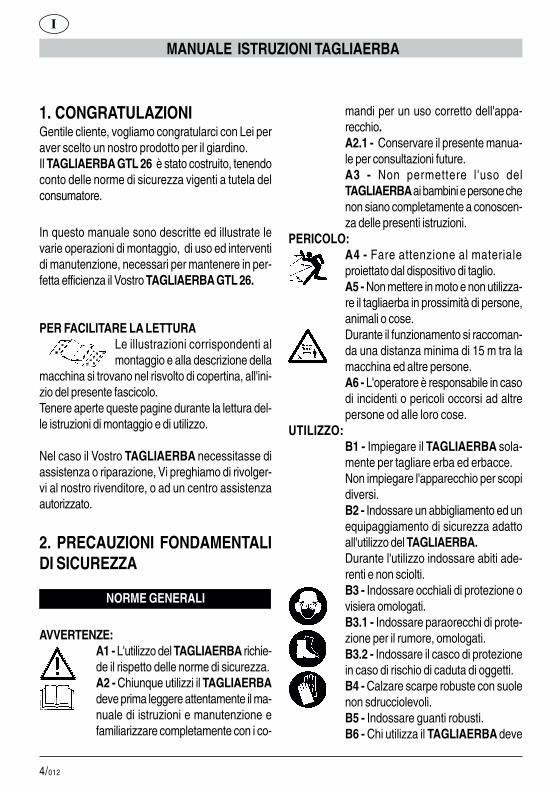
1. CONGRATULAZIONIGentile cliente, vogliamo congratularci con Lei peraver scelto un nostro prodotto per il giardino.Il TAGLIAERBA GTL 26 è stato costruito, tenendoconto delle norme di sicurezza vigenti a tutela delconsumatore.
In questo manuale sono descritte ed illustrate levarie operazioni di montaggio, di uso ed interventidi manutenzione, necessari per mantenere in per-fetta efficienza il Vostro TAGLIAERBA GTL 26.
PER FACILITARE LA LETTURALe illustrazioni corrispondenti almontaggio e alla descrizione della
macchina si trovano nel risvolto di copertina, all'ini-zio del presente fascicolo.Tenere aperte queste pagine durante la lettura del-le istruzioni di montaggio e di utilizzo.
Nel caso il Vostro TAGLIAERBA necessitasse diassistenza o riparazione, Vi preghiamo di rivolger-vi al nostro rivenditore, o ad un centro assistenzaautorizzato.
2. PRECAUZIONI FONDAMENTALIDI SICUREZZA
NORME GENERALI
AVVERTENZE:A1 - L'utilizzo del TAGLIAERBA richie-de il rispetto delle norme di sicurezza.A2 - Chiunque utilizzi il TAGLIAERBAdeve prima leggere attentamente il ma-nuale di istruzioni e manutenzione efamiliarizzare completamente con i co-
mandi per un uso corretto dell'appa-recchio.A2.1 - Conservare il presente manua-le per consultazioni future.A3 - Non permettere l'uso delTAGLIAERBA ai bambini e persone chenon siano completamente a conoscen-za delle presenti istruzioni.
PERICOLO:A4 - Fare attenzione al materialeproiettato dal dispositivo di taglio.A5 - Non mettere in moto e non utilizza-re il tagliaerba in prossimità di persone,animali o cose.Durante il funzionamento si raccoman-da una distanza minima di 15 m tra lamacchina ed altre persone.A6 - L'operatore è responsabile in casodi incidenti o pericoli occorsi ad altrepersone od alle loro cose.
UTILIZZO:B1 - Impiegare il TAGLIAERBA sola-mente per tagliare erba ed erbacce.Non impiegare l'apparecchio per scopidiversi.B2 - Indossare un abbigliamento ed unequipaggiamento di sicurezza adattoall'utilizzo del TAGLIAERBA.Durante l'utilizzo indossare abiti ade-renti e non sciolti.B3 - Indossare occhiali di protezione ovisiera omologati.B3.1 - Indossare paraorecchi di prote-zione per il rumore, omologati.B3.2 - Indossare il casco di protezionein caso di rischio di caduta di oggetti.B4 - Calzare scarpe robuste con suolenon sdrucciolevoli.B5 - Indossare guanti robusti.B6 - Chi utilizza il TAGLIAERBA deve
I
5/012
MANUALE ISTRUZIONI TAGLIAERBA
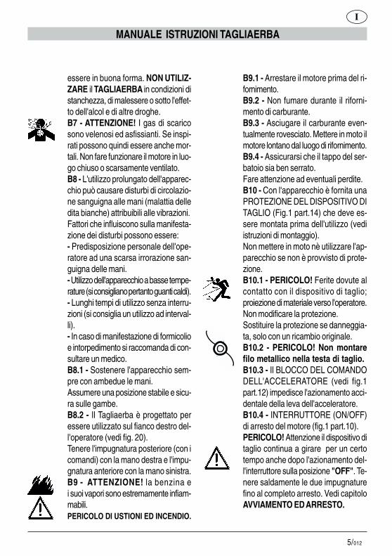
essere in buona forma. NON UTILIZ-ZARE il TAGLIAERBA in condizioni distanchezza, di malessere o sotto l'effet-to dell'alcol e di altre droghe.B7 - ATTENZIONE! I gas di scaricosono velenosi ed asfissianti. Se inspi-rati possono quindi essere anche mor-tali. Non fare funzionare il motore in luo-go chiuso o scarsamente ventilato.B8 - L'utilizzo prolungato dell'apparec-chio può causare disturbi di circolazio-ne sanguigna alle mani (malattia delledita bianche) attribuibili alle vibrazioni.Fattori che influiscono sulla manifesta-zione dei disturbi possono essere:- Predisposizione personale dell'ope-ratore ad una scarsa irrorazione san-guigna delle mani.- Utilizzo dell'apparecchio a basse tempe-rature (si consigliano pertanto guanti caldi).- Lunghi tempi di utilizzo senza interru-zioni (si consiglia un utilizzo ad interval-li).- In caso di manifestazione di formicolioe intorpedimento si raccomanda di con-sultare un medico.B8.1 - Sostenere l'apparecchio sem-pre con ambedue le mani.Assumere una posizione stabile e sicu-ra sulle gambe.B8.2 - Il Tagliaerba è progettato peressere utilizzato sul fianco destro del-l'operatore (vedi fig. 20).Tenere l'impugnatura posteriore (con icomandi) con la mano destra e l'impu-gnatura anteriore con la mano sinistra.B9 - ATTENZIONE! la benzina ei suoi vapori sono estremamente infiam-mabili.PERICOLO DI USTIONI ED INCENDIO.
B9.1 - Arrestare il motore prima del ri-fornimento.B9.2 - Non fumare durante il riforni-mento di carburante.B9.3 - Asciugare il carburante even-tualmente rovesciato. Mettere in moto ilmotore lontano dal luogo di rifornimento.B9.4 - Assicurarsi che il tappo del ser-batoio sia ben serrato.Fare attenzione ad eventuali perdite.B10 - Con l'apparecchio è fornita unaPROTEZIONE DEL DISPOSITIVO DITAGLIO (Fig.1 part.14) che deve es-sere montata prima dell'utilizzo (vediistruzioni di montaggio).Non mettere in moto nè utilizzare l'ap-parecchio se non è provvisto di prote-zione.B10.1 - PERICOLO! Ferite dovute alcontatto con il dispositivo di taglio;proiezione di materiale verso l'operatore.Non modificare la protezione.Sostituire la protezione se danneggia-ta, solo con un ricambio originale.B10.2 - PERICOLO! Non montarefilo metallico nella testa di taglio.B10.3 - Il BLOCCO DEL COMANDODELL'ACCELERATORE (vedi fig.1part.12) impedisce l'azionamento acci-dentale della leva dell'acceleratore.B10.4 - INTERRUTTORE (ON/OFF)di arresto del motore (fig.1 part.10).PERICOLO! Attenzione il dispositivo ditaglio continua a girare per un certotempo anche dopo l'azionamento del-l'interruttore sulla posizione "OFF". Te-nere saldamente le due impugnaturefino al completo arresto. Vedi capitoloAVVIAMENTO ED ARRESTO.
I
6/012
MANUALE ISTRUZIONI TAGLIAERBA
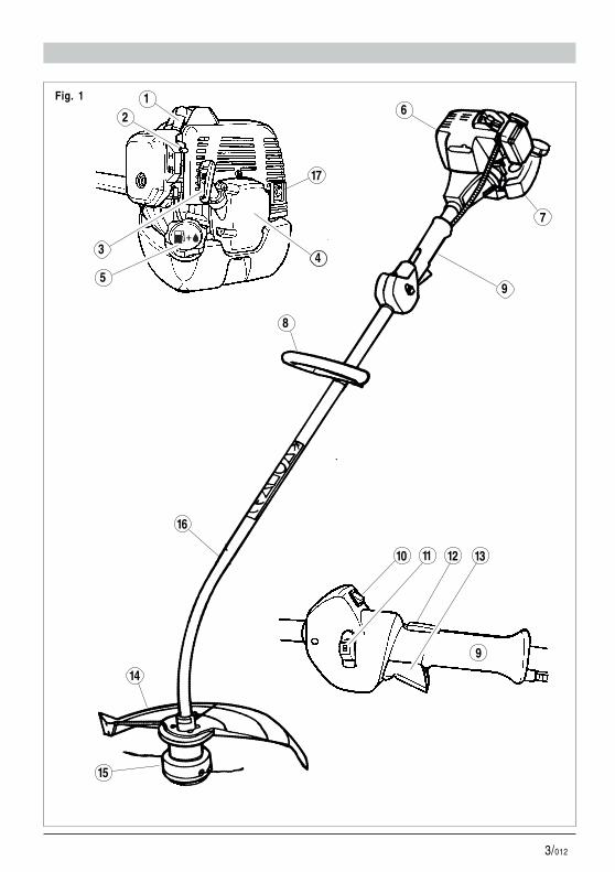
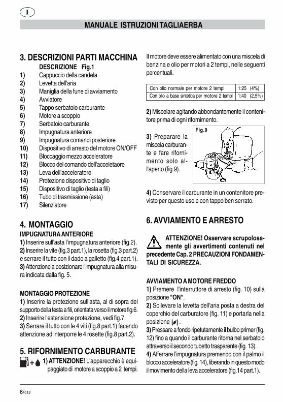
3. DESCRIZIONI PARTI MACCHINADESCRIZIONE Fig.1
1) Cappuccio della candela2) Levetta dell'aria3) Maniglia della fune di avviamento4) Avviatore5) Tappo serbatoio carburante6) Motore a scoppio7) Serbatoio carburante8) Impugnatura anteriore9) Impugnatura comandi posteriore10) Dispositivo di arresto del motore ON/OFF11) Bloccaggio mezzo acceleratore12) Blocco del comando dell'acceletaore13) Leva dell'acceleratore14) Protezione dispositivo di taglio15) Dispositivo di taglio (testa a fili)16) Tubo di trasmissione (asta)17) Silenziatore
4. MONTAGGIOIMPUGNATURA ANTERIORE1) Inserire sull'asta l'impugnatura anteriore (fig.2).2) Inserire la vite (fig.3 part.1), la rosetta (fig.3 part.2)e serrare il tutto con il dado a galletto (fig.4 part.1).3) Attenzione a posizionare l'impugnatura alla misu-ra indicata dalla fig. 5.
MONTAGGIO PROTEZIONE1) Inserire la protezione sull'asta, al di sopra delsupporto della testa a fili, orientata verso il motore fig.6.2) Inserire l'estensione protezione, vedi fig.7.3) Serrare il tutto con le 4 viti (fig.8 part.1) facendoattenzione ad interporre le 4 rosette (fig.8 part.2).
5. RIFORNIMENTO CARBURANTE 1) ATTENZIONE! L'apparecchio è equi- paggiato di motore a scoppio a 2 tempi.
Il motore deve essere alimentato con una miscela dibenzina e olio per motori a 2 tempi, nelle seguentipercentuali.
Con olio normale per motore 2 tempi 1:25 (4%) Con olio a base sintetica per motore 2 tempi 1:40 (2,5%)
2) Miscelare agitando abbondantemente il conteni-tore prima di ogni rifornimento.
Fig.93) Preparare lamiscela carburan-te e fare riforni-mento solo al-l'aperto (fig.9).
4) Conservare il carburante in un contenitore pre-visto per questo uso e con tappo ben serrato.
6. AVVIAMENTO E ARRESTO
ATTENZIONE! Osservare scrupolosa-mente gli avvertimenti contenuti nel
precedente Cap. 2 PRECAUZIONI FONDAMEN-TALI DI SICUREZZA.
AVVIAMENTO A MOTORE FREDDO1) Premere l'interruttore di arresto (fig. 10) sullaposizione "ON".2) Sollevare la levetta dell'aria posta a destra delcoperchio del carburatore (fig. 11) e portarla nellaposizione .3) Pressare a fondo ripetutamente il bulbo primer (fig.12) fino a quando il carburante ritorna nel serbatoioattraverso il secondo tubetto trasparente (fig. 13).4) Afferrare l'impugnatura premendo con il palmo ilblocco acceleratore (fig. 14), liberando in questo modoil movimento della leva acceleratore (fig.14 part.1).
I

7/012
MANUALE ISTRUZIONI TAGLIAERBA
5) Premere a fondo la leva dell'acceleratore (fig.15).6) Mantenendo premute le leve (fig.15) spingere afondo il bottone del mezzo acceleratore (fig.16).7) Mantenendo a fondo il bottone rilasciare la levadell'acceleratore .In questo modo il bottone di blocco del mezzo acce-leratore rimane inserito, quindi le mani rimangonoentrambe disponibili per l'avviamento.8) Tirare a fondo fino a 3 volte la maniglia della funedi avviamento (fig.17).9) Spingere in giù la levetta dell'aria del carburato-re (fig.18).10) Tirare la fune di avviamento (fig.17) fino allamessa in moto.
ATTENZIONE - PERICOLO !! Il motore siavvia e rimane accelerato a metà quindi il
dispositivo di taglio è in rotazione.Lasciare funzionare il motore per alcuni secondi.
11) Premendo brevemente la leva acceleratore (fig.19 part.1) il bottone del mezzo acceleratore sidisinserisce automaticamente. Il motore rimane cosìin moto al regime minimo ed il dispositivo di taglio siarresta dopo un breve tempo.
ARRESTO MOTORE
1) Per arrestare il motore, portare l'interruttore (fig.19 part. 2) nella posizione "OFF".
ATTENZIONE! il dispositivo di taglio conti-nua a girare per un certo tempo anche
dopo l'azionamento dell'interruttore sulla posizione"OFF". Tenere saldamente le due impugnature finoal completo arresto.
Fig.11
Fig.12 Fig.13
Fig.14 Fig.15
Fig.16
Fig.17
Fig.18 Fig.19
�
�
�
�
�
�
� �
�
1
2
1
Fig.10
�
ON
OFF
ON
OFF
AVVIAMENTO A MOTORE CALDOProcedere come a motore freddo ma con la levettadell'aria abbassata (vedi fig.18).
I

8/012
MANUALE ISTRUZIONI TAGLIAERBA
7. UTILIZZOCOME UTILIZZARE IL TAGLIAERBA1) Tenere l'apparecchio sul fianco destro come in-dicato in fig.20.
REGISTRAZIONE DELLA LUNGHEZZA DELFILO DI TAGLIOLa testa a fili è del tipo semiautomatico e permette diripristinare la giusta lunghezza dei fili senza arre-stare il motore.Prima che il filo di taglio si sia usurato fino a metàlunghezza fare una breve pressione con la testasul terreno, tenendo il motore ad alta velocità (fig.21).Con questa operazione il filo si svolge (per effettocentrifugo) dalla bobina interna.La giusta lunghezza viene automaticamente ripristi-nata per mezzo della lametta posta sulla protezione.
TAGLIO DI ERBATenendo la testa di taglio parallela al terreno, avan-zare oscillando a destra e sinistra (fig.23).Tenere il motore a pieni giri per effettuare il taglionetto.
TAGLIO INTORNO AD OSTACOLI, PIANTE,RECINZIONISfiorare l'ostacolo con l'estremità del filo (fig.23).L'inclinazione della testa (fig.22) può migliorare l'ef-ficienza del taglio. Non urtare gli ostacoli con la testadi taglio per evitare rotture nette dei fili.In caso di rottura dei fili procedere come per lasostituzione.
8. SOSTITUZIONE DEL FILOÉ possibile montare: un nuovo rocchetto completodi filo oppure riavvolgere un nuovo filo sul rocchet-to originale.
A) Utilizzare filo di diametro 2 mm in plastica appositoper tagliaerba a filo.
ATTENZIONE PERICOLO! NON UTILIZ-ZARE ASSOLUTAMENTE FILO METAL-LICO.
B) SMONTAGGIO BOBINA1) Svitare in senso antiorario il pomolo (fig.24).2) Sfilare il rocchetto dal corpo della testa (fig.25-26).3) Pulire accuratamente l'interno del corpo (fig.27)verificando il grado di usura dei denti interni (fig.28),in caso di evidente usura sostituire l'intera testa.
C) AVVOLGIMENTO DEL FILOUsare una lunghezza di filo non superiore a 8 m.1) Infilare i due capi del filo nei due fori del rocchetto.Tirarli dal lato opposto appaiandoli (fig.29).2) Avvolgere i due tratti di filo accoppiati sul rocchet-to, seguendo il senso della freccia impressa sul roc-chetto stesso (fig.30).3) Per facilitare il reinserimento del rocchetto nelcorpo, fissare le due estremità del filo nelle due ap-posite feritoie (fig.31).
D) RIMONTAGGIO ROCCHETTO1) Infilare i due capi attraverso i passafilo (fig.32-33).2) Inserire nella testa la molla e quindi il rocchetto.3) Tirare decisamente i due capi del filo perchè sisfilino dalle feritoie (fig.34).4) Avvitare a fondo il pomolo in senso orario (fig.35).Sostituire il pomolo quando è usurato.
9. MANUTENZIONECANDELAAlmeno una volta all'anno od in caso di difficoltà dimessa in moto, verificare lo stato della candela diaccensione. Attendere che il motore si raffreddi pri-ma dell'operazione.
I
9/012
MANUALE ISTRUZIONI TAGLIAERBA
1) Sfilare il cappuccio e svitare la candela con lachiave in dotazione (fig.36).In caso di eccessive incrostazioni e notevole usuradegli elettrodi, sostituire la candela con una di tipoequivalente (fig.37-38).Un eccesso di incrostazioni può essere dovuto a:# Eccessiva percentuale di olio nel carburante e/oqualità non appropriata dell'olio.# Filtro aria parzialmente ostruito.2) Avvitare la candela a mano fino a fondo filetto perevitare danni alla sua sede. Usare l'apposita chia-ve solo per il serraggio (fig.36).
FILTRO ARIAPulire periodicamente il filtro aria; frequentementese si opera in aree polverose.1) Svitare la vite a galletto del coperchio (fig.39).2) Lavare con acqua e detergente neutro.3) Fare asciugare il filtro prima di riposizionarlo(fig.40).Sostituire il filtro se danneggiato per noncompromettere la durata del motore.
FILTRO PESCANTE DEL CARBURANTESostituire una volta all'anno il filtro estraendolo conun gancio attraverso l'apertura di rifornimento delserbatoio.
RETINA PARASCINTILLE DEL SILENZIATORE# Nel foro di scarico del gas è inserito un anello conretina (parte più sporgente).# A causa dei depositi la retina tende a ostruirsiriducendo notevolmente le prestazioni del motore.# Estrarre l'anello con retina per mezzo di una pin-za a becchi (fig.41).
REGIME MINIMO DEL MOTORE# Verificare ad ogni utilizzo che al regimeminimo il dispositivo di taglio non sia in rota-zione.
# Se tende a ruotare rivolgersi ad un centro diassistenza per l'intervento di regolazione.
VERIFICA VITI E PARTI ROTANTI# Prima di ogni utilizzo controllare che non ci sianoviti o parti allentate e che non ci siano cricche onotevoli usure nel dispositivo di taglio.# Sostituire le parti danneggiate prima dell'utilizzo.
PULIZIA E RIMESSAGGIO# In caso di interruzione di utilizzo superiore a 2mesi, vuotare il serbatoio del carburante.# Non pulire con liquidi aggressivi.# Conservare l'apparecchio in luogo asciutto e si-curo non accessibile ai bambini.
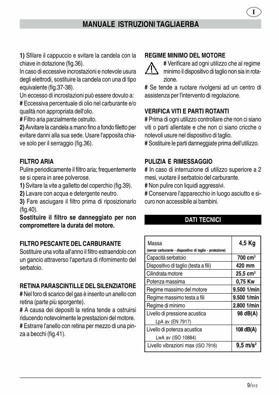
DATI TECNICI
Massa 4,5 Kg (senza carburante - dispositivo di taglio - protezione)
Capacità serbatoio 700 cm3
Dispositivo di taglio (testa a fili) 420 mm Cilindrata motore 25,5 cm3
Potenza massima 0,75 Kw Regime massimo del motore 9.500 1/min Regime massimo testa a fili 9.500 1/min Regime di minimo 2.800 1/min Livello di pressione acustica 98 dB(A) LpA av (EN 7917)
Livello di potenza acustica 108 dB(A) LwA av (ISO 10884)
Livello vibrazioni max (ISO 7916) 9,5 m/s2
I

10/012
A3 - Do not let children and personswho are not completely aware of theseinstructions use the GRASSTRIMMER.
DANGER:A4 - Beware of objects hurled by theline head.A5 - Do not start up and do not use thegrass trimmer near people, otheranimals or obtrusive objects.During operation we recommendkeeping a minimum distance of 15 mbetween the machine and other people.A6 - The operator is responsible forany accidents or hazards that mayoccur to other persons or theirbelongings.
OPERATION:B1 - Use the GRASS TRIMMER onlyto cut grass and weeds.Do not use the device for otherpurposes.B2 - Wear clothing and safety gearsuitable for GRASS TRIMMERoperation.During operation wear close-fittingclothing and not loose or baggygarments.B3 - Wear approved protective gogglesor visor.B3.1 - Wear approved noise-dampingearplugs.B3.2 - Wear a safety helmet in areaswhere objects are likely to fall.B4 - Wear sturdy shoes with non-slipsoles.B5 - Wear sturdy gloves.B6 - GRASS TRIMMER operators mustbe in good physical condition. DO NOTUSE the GRASS TRIMMER if you feel
GRASS TRIMMER OPERATING MANUAL
GB
1. CONGRATULATIONSDear Client - May we congratulate you for havingchosen one of our products for your garden.The model GTL 26 GRASS TRIMMER has beenmanufactured in accordance with the current safetyregulations which protect the consumer.
This manual describes and illustrates the variousoperations for assembly, use and maintenance whichare required in order to keep your GTL 26 GRASSTRIMMER in perfect condition.
TO FACILITATE READINGThe illustrations about the assemblyare to be found on the back of
cover, at the beginning of this booklet. Keep thesepages open while reading the assembly instructions.
Should your GRASS TRIMMER need servicingor repair, please contact your retailer or anauthorised service centre.
2.ESSENTIAL SAFETY PRECAU-TIONS
GENERAL REGULATIONS
PRECAUTIONS:A1 - Safety regulations must be heededwhen using the GRASS TRIMMER.A2 - All users of the GRASS TRIMMERmust first carefully read the maintenanceand operating manual and familiarisethemselves fully with all controls forcorrect operation of the device.A2.1 - Keep this manual for futurereference.

11/012
tired, ill or are under the influence ofalcohol or other drugs.B7 - CAUTION! Exhaust fumes aretoxic and asphyxiating. If inhaled, thesefumes may even be lethal. Do not startthe engine in closed or poorly ventilateenvironments.B8 - Prolonged use of the device mayhinder blood circulation to the hands(Raynaud’s phenomenon) due tovibrations.The following factors may pose a risk tothe operator’s health:- Operator is predisposed to poor bloodcirculation in the hands.- The device is used in cold weather(warm gloves are stronglyrecommended).- The device is used non-stop for longperiods (we suggest using it atintervals).- If you feel a tingling sensation or numbin any way, please seek medicalattention.B8.1 - Always hold the device with bothhands.Stand in a safe and steady position onboth legs.B8.2 - The grass trimmer is designedto be used on your right-hand side (seefig. 20).Hold the rear handle with controls withyour right hand and the front handlewith your left hand.B9 - CAUTION! Petrol and its vapoursare highly flammable.BURNING AND FIRE HAZARDS.B9.1 - Stop the engine before refuelling.B9.2 - Do not smoke while refuelling.B9.3 - Wipe off any fuel that may have
spilled. Start up the engine away fromthe place where it was refuelled.B9.4 - Make sure the tank cap istightened properly.Beware of any leaks.B10 - The device is supplied with aCUTTING ATTACHMENT GUARD(Fig.1 item14) that must be mountedbefore operation (see assemblyinstructions).Do not start up or use the device if it isnot equipped with the guard.B10.1 - DANGER! Injuries caused bycontact with the line head. Guardagainst objects hurled towards theoperator.Do not modify the guard.If damaged, replace the guard only withan original spare part.B10.2 - DANGER! Do not fit metalwire in the line head.B10.3 - The THROTTLE TRIGGERLOCKOUT (see fig.1 item 12) stopsaccidental operation of the throttlecontrol lever.B10.4 - Engine power ON/OFFSWITCH (fig.1 item10).DANGER! Caution! The line headcontinues to spin for a while even afterthe power switch has been shut OFF.Hold both handles firmly until the linehead comes to a complete stop. Seesection titled STARTING ANDSTOPPING.
GRASS TRIMMER OPERATING MANUAL
GB
12/012
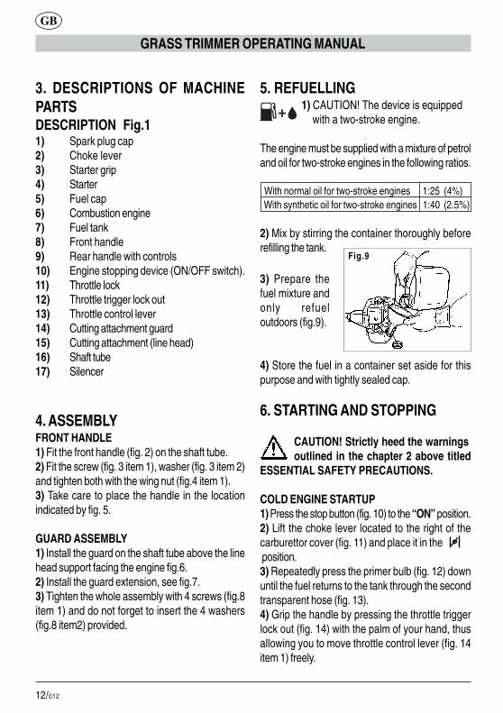
3. DESCRIPTIONS OF MACHINEPARTSDESCRIPTION Fig.11) Spark plug cap2) Choke lever3) Starter grip4) Starter5) Fuel cap6) Combustion engine7) Fuel tank8) Front handle9) Rear handle with controls10) Engine stopping device (ON/OFF switch).11) Throttle lock12) Throttle trigger lock out13) Throttle control lever14) Cutting attachment guard15) Cutting attachment (line head)16) Shaft tube17) Silencer
4. ASSEMBLYFRONT HANDLE1) Fit the front handle (fig. 2) on the shaft tube.2) Fit the screw (fig. 3 item 1), washer (fig. 3 item 2)and tighten both with the wing nut (fig.4 item 1).3) Take care to place the handle in the locationindicated by fig. 5.
GUARD ASSEMBLY1) Install the guard on the shaft tube above the linehead support facing the engine fig.6.2) Install the guard extension, see fig.7.3) Tighten the whole assembly with 4 screws (fig.8item 1) and do not forget to insert the 4 washers(fig.8 item2) provided.
5. REFUELLING 1) CAUTION! The device is equipped with a two-stroke engine.
The engine must be supplied with a mixture of petroland oil for two-stroke engines in the following ratios.
With normal oil for two-stroke engines 1:25 (4%) With synthetic oil for two-stroke engines 1:40 (2.5%)
2) Mix by stirring the container thoroughly beforerefilling the tank.
GRASS TRIMMER OPERATING MANUAL
Fig.9
3) Prepare thefuel mixture andonly refueloutdoors (fig.9).
4) Store the fuel in a container set aside for thispurpose and with tightly sealed cap.
6. STARTING AND STOPPING
CAUTION! Strictly heed the warningsoutlined in the chapter 2 above titled
ESSENTIAL SAFETY PRECAUTIONS.
COLD ENGINE STARTUP1) Press the stop button (fig. 10) to the “ON” position.2) Lift the choke lever located to the right of thecarburettor cover (fig. 11) and place it in the position.3) Repeatedly press the primer bulb (fig. 12) downuntil the fuel returns to the tank through the secondtransparent hose (fig. 13).4) Grip the handle by pressing the throttle triggerlock out (fig. 14) with the palm of your hand, thusallowing you to move throttle control lever (fig. 14item 1) freely.
GB

13/012
GRASS TRIMMER OPERATING MANUAL
5) Press the throttle control lever right down (fig. 15).6) Hold the levers (fig.15) down and push the throttlelock button (fig.16) right down.7) Hold the button down and release the throttlecontrol lever.This should lock the throttle lock button, so both handsare free to operate the device.8) Pull the starter grip (fig.17) completely as manyas 3 times.9) Push the carburettor choke lever (fig.18) down .10) Pull the start cord (fig.17) until the engine starts up.
CAUTION - DANGER !! The engine startsat half acceleration and as a result the line
head is spinning.Let the engine run a few seconds.
11) Press the throttle control lever briefly (fig. 19item1) and the throttle lock button will disengageautomatically. The engine will thus return to idle andthe line head will stop after a short while.
STOP ENGINE
1) To stop the engine, shut the power switch (fig. 19item 2) “OFF”.
CAUTION! The line head continues to spinfor a while even after the power switch has
been shut OFF. Hold both handles firmly until theline head comes to a complete stop.
WARM ENGINE STARTUPProceed as with a cold engine startup but with thechoke lever down (see fig.18).
Fig.11
Fig.12 Fig.13
Fig.14 Fig.15
Fig.16
Fig.17
Fig.18 Fig.19
�
�
�
�
�
�
� �
�
1
2
1
Fig.10
�
ON
OFF
ON
OFF
GB

14/012
7. OPERATIONHOW TO USE THE GRASS TRIMMER1) Hold the device on the right-hand side as shownin fig. 20.
ADJUSTING THE LENGTH OF THE CUTTINGLINEThe line head is semiautomatic and allows the userto adjust the correct line length without stopping theengine.Before half the length of the cutting line is worn,press briefly with the head on the ground, whilekeeping the engine at full speed (fig. 21).This operation unwinds the line (away from thecentre) from inner reel. The correct length isautomatically restored by means of the blade locatedon the guard.
TRIMMING GRASSWith the line head held parallel to the ground,proceed swinging the trimmer to the right and left(fig. 23). Keep the engine running at full speed for aclean trim.
TRIMMING AROUND OBSTACLES, PLANTSAND FENCESKeep the end of the line (fig. 23) just clear of obstacles.The inclination of the head (fig. 22) may improvetrimming efficiency. Do not knock obstacles with theline head to avoid cutting lines.Should lines snap, replace them as outlined below.
8. REPLACING A CUTTING LINEUser can install: a new spool complete with line orrewind a new line on the original spool.A) Use a plastic line 2 mm in diameter speciallydesigned for strimmers.
ATTENTION DANGER! DO NOT USEMETAL WIRE AT ALL!
B) DETACHING A SPOOL1) Unscrew the knob anticlockwise (fig. 24).2) Remove the spool from the housing of the head(fig. 25-26).3) Thoroughly clean the inside of the housing (fig.27) and check how much the internal teeth (fig. 28)are worn. If they are visibly worn, replace the wholehead.
C) WINDING A LINEUse a length of line no greater than 8 m.1) Insert the two ends of the line in the two holes inthe spool. Pull them from the opposite side and crossthem in the middle (fig. 29).2) Wind the two coupled lengths of line on the spool,following the direction of the arrow printed on thespool itself (fig. 30).3) To make it easier to reinstall the spool in thehousing, attach both ends of the line in the two slotsprovided (fig. 31).
D) REFITTING A SPOOL1) Insert both ends through the guiding slit (fig. 32-33).2) Insert the spring and then the spool in the head.3) Firmly pull out both ends of the line as far aspossible through the slots (fig. 34).4) Screw the knob fully clockwise (fig. 35). Replacethe knob when it is worn.
9.MAINTENANCESPARK PLUGAt least once a year or if the engine has problemsstarting up properly, check the condition of the sparkplug. Wait for the engine to cool before operation.1) Remove the cap and unscrew the spark plugwith the wrench< provided (fig. 36).
GRASS TRIMMER OPERATING MANUAL
GB

15/012
If the electrodes are excessively soiled or are veryworn, replace the spark plug with an equivalent(fig. 37-38).Excessive soiling may be due to:# The oil ratio used in fuel is too high and/or oil is notof an appropriate type.# Air filter is partly clogged.2) Screw the spark plug manually as far as possibleto avoid damaging its socket. Use the wrenchprovided only to tighten it (fig. 36).
AIR FILTERClean the air filter periodically or frequently whenworking in dusty areas.1) Unscrew the wing nut from the cover (fig. 39).2) Wash with water and neutral detergent.3) Dry the filter before replacing it (fig.40).Replace the filter if it is damaged so as notcompromise engine life.
FUEL INTAKE FILTERReplace the filter once a year by removing it with ahook through tank-refilling outlet.
SILENCER SPARK ARRESTER SCREEN# A ring with a screen is inserted in the exhaust gasoutlet (outermost part).# Deposits tend to block the screen and considerablyreduce engine performance.# Remove the ring with a screen using a pair ofpliers (fig.41).
ENGINE IDLING SPEED# Before use, always make sure the linehead does not turn when the engine is idling.
# If it tends to turn, contact a service centre foradjustment.
GRASS TRIMMER OPERATING MANUAL
CHECKING SCREWS AND ROTATING PARTS# Before use, always make sure there are no screwsor loose parts and there are no cracks or wornsections in the line head.# Replace any damaged parts before reuse.
CLEANING AND STORAGE# If the trimmer is not used for over 2 months, emptythe fuel tank.# Do not clean with aggressive liquids.# Store the device in a dry and safe place inaccessibleto children.
TECHNICAL DATA
Mass 4,5 Kg (with out fuel, cutting attacment and guard)
Fuel tank volume 700 cm3
Cutting attacment (string head) 420 mm Engine dispacement 25,5 cm3
Engine performance 0,75 Kw Maximum engine speed 9.500 1/min Maximum speed of spindle 9.500 1/min Engine speed at idling 2.800 1/min Sound pressure level 98 dB(A) LpA av (EN 7917)
Sound power level 108 dB(A) LwA av (ISO 10884)
Vibration level (ISO 7916) 9,5 m/s2
GB

16/012
F
1. FÉLICITATIONSChère cliente, Cher client, Nous vous félicitonsd'avoir choisi un de nos produits pour le jardin. LeCOUPE-HERBE GTL 26 a été conçu en tenantcompte des normes de sécurité en vigueur pourprotéger le consommateur.
Ce manuel contient des illustrations et desinstructions de montage, d'installation, d'emploi etd'entretien détaillées qui vous permettront demaintenir votre COUPE-HERBE GTL 26.
POUR FACILITER LA LECTURELes illustrations qui correspondentau montage se trouvent dans le
volet de la couverture, au début de la présentepublication.Laisser ces pages ouvertes pendant que vous lisezles instructions de montage.
Si vous avez besoin d'assistance pour fairefonctionner ou réparer votre COUPE-HERBE,veuillez vous adresser à votre revendeur ou à undépanneur agréé.
2. PRECAUTIONS FONDAMEN-TALES DE SECURITE
NORMES GENERALES
AVIS:A1 - L’utilisation de la COUPE-HERBEdemande le respect des normes de sé-curité.A2 - Les utilisateurs de la COUPE-HERBE doivent lire tout d’abord et avecattention le manuel d’instruction et d’en-tretien afin d’apprendre parfaitement les
MANUEL D’INSTRUCTION COUPE-HERBE
commandes pour une utilisation correctede la machine.A2.1 - Garder ce manuel pour le con-sulter à l’avenir.A3 - L’utilisation de la COUPE-HERBEest interdite aux enfants et aux personnesqui ne connaissent pas ces instructions.
DANGER:A4 - Faire attention aux matériaux sor-tant du dispositif de coupe.A5 - Ne pas mettre en marche ni utiliserla COUPE-HERBE près de person-nes, d’animaux ou de choses.Pendant le fonctionnement nous con-seillons une distance minimum de 15 mentre la machine et les personnes.A6 - L’opérateur est responsable encas d’accidents ou de risques auxquel-les des personnes ou des objets sontsoumis.
UTILISATION:B1 - Utiliser la COUPE-HERBE seule-ment pour tondre le gazon et les mau-vaises herbes.Ne pas utiliser l’appareil pour des ob-jectifs différents.B2 - Mettre des vêtements et un équi-pement de sécurité indiqué pour l’utili-sation de la COUPE-HERBE.Pendant l’utilisation mettre des vête-ments collants et éviter des vêtementsamples.B3 - Mettre des lunettes de protectionou une visière homologuées.B3.1 - Mettre un protège-oreilles pourles bruits, homologué.B3.2 - Mettre le casque de protection sides objets risquent de tomber.B4 - Mettre des chaussures robustesavec des semelles anti-dérapage.B5 - Mettre des gants robustes.
17/012
F
MANUEL D’INSTRUCTION COUPE-HERBE
B6 - Les utilisateurs de la COUPE-HERBE doivent être en forme. NE PASUTILISER COUPE-HERBE en cas defatigue, de malaise, sous l’effet de l’al-cool et d’autres drogues.B7 - ATTENTION! les gaz d’échappe-ment sont toxiques et asphyxiants; unefois inspirés, ils peuvent être mortels.Le moteur ne doit jamais fonctionnerdans un endroit fermé et peu ventilé.B8 - L’utilisation prolongée de l’appa-reil peut provoquer des troubles de lacirculation sanguine des mains (mala-die des doigts blancs) provoqués parles vibrations.Des facteurs qui exercent un impact surla manifestation peuvent être les sui-vants.- Prédisposition personnelle de l’opé-rateur à une mauvaise circulation san-guine dans les mains.- Utilisation de l’appareil à de bassestempératures (nous conseillons doncdes gants chauds).- De longues périodes d’utilisation sansinterruption (nous conseillons une utili-sation à intervalles).- En cas de fourmillement et engourdis-sement, nous conseillons de s’adres-ser à un médecin.B8.1 - Prendre toujours l’appareil avecles deux mainsPrendre un position stable et sûre surles jambes.B8.2 - La COUPE-HERBE est conçuepour une utilisation du côté droit de l’opé-rateur (voir fig. 20).Tenir la poignée postérieure (aveccommandes) avec la main droite et lapoignée antérieure avec la main gau-che.
B9 - ATTENTION! l’essence et sesvapeurs sont très inflammables.RISQUES DE BRULURES ET D’IN-CENDIEB9.1 - Arrêter le moteur avant le ravi-taillement.B9.2 - Ne pas fumer pendant le ravi-taillement de carburant.B9.3 - Sécher le carburant éventuelle-ment renversé. Mettre en marche lemoteur loin du lieu de ravitaillement.B9.4 - S’assurer que le bouchon duréservoir est bien serré.Faire attention à toute perte de carbu-rant.B10 - L’appareil est fourni avec unePROTECTION DU DISPOSITIF DECOUPE (Fig.1 dét.14-15) qui doit êtremontée avant son utilisation (voir ins-tructions de montage).Ne pas mettre en marche ni utiliser l’ap-pareil sans protection.B10.1 - DANGER! Blessures provo-quées par le contact avec le dispositifde coupe; matériaux éjectés vers l’opé-rateur.Ne pas modifier la protection.Ne remplacer toute protection endom-magée que par une rechange origi-nale.B10.2 - DANGER! Ne pas monter lefil en métal dans la tête de coupe.B10.3 - LE BLOCAGE DE LA COM-MANDE DE L’ACCELERATEUR (voirfig.1 dét.12): empêche l’actionnementaccidentel du levier de l’accélérateur.B10.4 - INTERRUPTEUR (ON/OFF)d’arrêt du moteur (fig.1 dét.10).DANGER! Attention: le dispositif decoupe continue à tourner pour quel-ques instants même après
18/012
F
MANUEL D’INSTRUCTION COUPE-HERBE
l’actionnement de l’interrupteur en po-sition «OFF». Tenir solidement les deuxpoignées jusqu’à l’arrêt complet. Voir lechapitre DEMARRAGE ET ARRET.
3. DESCRIPTION PARTIESMACHINE
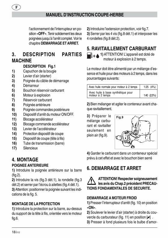
DESCRIPTION Fig.11) Capuchon de la bougie2) Levier d’air (starter)3) Poignée du câble de démarrage4) Démarreur5) Bouchon réservoir carburant6) Moteur à explosion7) Réservoir carburant8) Poignée antérieure9) Poignée commandes postérieure10) Dispositif d’arrêt du moteur ON/OFF.11) Blocage accélérateur12) Blocage commande accélérateur13) Levier de l’accélérateur14) Protection dispositif de coupe15) Dispositif de coupe (tête à fils)16) Tube de transmission (barre)17) Silencieux
4. MONTAGEPOIGNEE ANTERIEURE1) Introduire la poignée antérieure sur la barre(fig.2).2) Introduire la vis (fig.3 dét.1), la rondelle (fig.3dét.2) et serrer par l’écrou à ailettes (fig.4 dét.1).3) Attention: positionner la poignée suivant les indi-cations de la fig. 5.
MONTAGE DE LA PROTECTION1) Introduire la protection sur la barre, au-dessusdu support de la tête à fils, orientée vers le moteurfig.6.
2) Introduire l’extension protection, voir fig.7.3) Serrer par les 4 vis (fig.8 dét.1) et interposer les4 rondelles (fig.8 dét.2).
5. RAVITAILLEMENT CARBURANT 1) ATTENTION! L’appareil est doté de moteur à explosion à 2 temps.
Le moteur doit être alimenté par un mélange d’es-sence et huile pour des moteurs à 2 temps, dans lespourcentages suivants:
Avec huile normale pour moteur à 2 temps 1:25 (4%)
Avec huile à base synthétique pour moteur à 2 temps 1:40 (2,5%)
2) Bien mélanger et agiter le conteneur avant cha-que ravitaillement.
3) Préparer lemélange carbu-rant et ravitaillerseulement enplein air (fig.9).
Fig.9
4) Garder le carburant dans un conteneur spécialprévu à cet effet et avec le bouchon bien serré
6. DEMARRAGE ET ARRET
ATTENTION! Respecter soigneusementles avis du Chap.2 précédent PRECAU-
TIONS FONDAMENTALES DE SECURITE.
DEMARRAGE A MOTEUR FROID1) Presser l’interrupteur d’arrêt (fig. 10) en position«ON».2) Soulever le levier d’air (starter) à droite du cou-vercle du carburateur (fig. 11) en position .3) Presser à fond plusieurs fois le bulbe d’amor-

19/012
F
MANUEL D’INSTRUCTION COUPE-HERBE
Fig.11
Fig.12 Fig.13
Fig.14 Fig.15
Fig.16
Fig.17
Fig.18 Fig.19
�
�
�
�
�
�
� �
�
1
2
1
Fig.10
�
ON
OFF
ON
OFF
après la mise de l’interrupteur en position «OFF».Tenir solidement les deux poignées jusqu’à l’arrêtcomplet.
DEMARRAGE A MOTEUR CHAUDAppliquer la même procédure du moteur froid, maisavec le levier d’air (starter) baissé (voir fig.18).
çage (fig. 12) jusqu’à ce que le carburant retournedans le réservoir à travers le deuxième tube trans-parent (fig. 13).4) Saisir la poignée et presser avec la paume leblocage de l’accélérateur (fig. 14), pour dégagerainsi le mouvement du levier de l’accélérateur (fig.14dét.1).5) Presser à fond le levier de l’accélérateur (fig.15).6) Sans relâcher les leviers (fig.15) presser à fondle poussoir de l’accélérateur (fig.16).7) Presser à fond le poussoir et relâcher le levierde l’accélérateur.De cette façon le poussoir de blocage de l’accéléra-teur est toujours enclenché, donc les mains sontdisponibles pour la mise en marche.8) Tirer à fond jusqu’à 3 fois la poignée du câble dedémarrage (fig.17).9) Pousser le levier de l’air du carburateur (fig.18).10) Tirer le câble de démarrage (fig.17) jusqu’à lamise en marche.
ATTENTION - DANGER !! Le moteur démarre, accéléré à moitié, donc le dispositif
de coupe est en rotation.Laisser le moteur en marche pour quelques secon-des.
11) Presser pour quelques instants le levier accélé-rateur (fig. 19 dét.1): le poussoir accélérateur estdébranché automatiquement. Le moteur reste ainsien marche au régime ralenti et le dispositif de coupes’arrête après quelques secondes.
ARRET MOTEUR
1) Pour arrêter le moteur mettre l’interrupteur (fig.19 dét. 2) en position «OFF».
ATTENTION! le dispositif de coupe continue à tourner pour quelques instants même
20/012
F
MANUEL D’INSTRUCTION COUPE-HERBE
7. UTILISATIONUTILISATION DE LA COUPE-HERBE1) Tenir l’appareil du côté droit selon les indicationsde la fig.20.
REGLAGE DE LA LONGUEUR DU FIL DECOUPELa tête à fils est du type semi-automatique et permetde rétablir la longueur exacte des fils sans arrêter emoteur.Avant l’usure du fil de coupe jusqu’à moitié de salongueur, presser la tête au sol pour quelques ins-tants, avec le moteur à haute vitesse (fig.21).Cette opération déroule le fil de la bobine interne(effet centrifuge). La longueur correcte est rétablieautomatiquement par la lame située sur la protec-tion.
TONDAGE DU GAZONAvec la tête de coupe parallèle au sol, avancer pardes oscillations à droite et à gauche (fig.23). Tenirle moteur au régime de pointe pour effectuer unecoupe nette.
COUPE AUTOUR D’OBSTACLES, DE PLAN-TES, D’ENCEINTESEffleurer l’obstacle avec l’extrémité du fil (fig.23).L’inclinaison de la tête (fig.22) peut améliorer la per-formance de coupe. Ne pas heurter les obstaclesavec la tête de coupe pour éviter des ruptures net-tes des fils.En cas de rupture des fils appliquer la même procé-dure du remplacement.
8. REMPLACEMENT DU FILIl est possible de monter un nouvelle bobine de filou bien enrouler un fil neuf sur la bobine originale.A) Utiliser un fil diamètre 2 mm en plastique spécialpour coupe-herbe.
ATTENTION DANGER! NE JAMAIS UTI-LISER DU FIL EN METAL.
B) DEMONTAGE BOBINE1) Dévisser le pommeau dans le sens contraire auxaiguilles d’une montre (fig.24).2) Extraure la bobine du corps de la tête (fig.25-26).3) Nettoyer soigneusement à l’intérieur du corps(fig.27) et vérifier l’usure des dents internes (fig.28).Remplacer la tête toute entière en cas d’usure évi-dente.
C) ENROULEMENT DU FILUtiliser un fil ayant une longueur non supérieure à10 m.1) Introduire les deux bouts du fil dans les deuxorifices de la bobine. Extraire et apparier ceux-ci ducôté opposé (fig.29).2) Enrouler les deux bouts de fil appariés sur labobine, selon la direction de la flèche imprimée surla même bobine (fig.30).3) Pour une réinsertion plus facile de la bobine dansle corps, fixer les deux bouts du fil dans les rainuresprévues à cet effet (fig.31).
D) REMONTAGE BOBINE1) Insérer les deux bouts par les guide-fils (fig.32-33).2) Introduire le ressort et la bobine dans la tête.3) Tirer avec force les deux bouts du fil pour lesextraire des rainures (fig.34).4) Visser à fond le pommeau dans le sens desaiguilles d’une montre (fig.35). Remplacer le pom-meau usé.
9. ENTRETIENBOUGIEAu moins une fois par an ou en cas de difficulté dansle démarrage, vérifier l’état de la bougie d’allumage.Attendre le refroidissement du moteur avant l’opé-ration.
21/012
F
MANUEL D’INSTRUCTION COUPE-HERBE
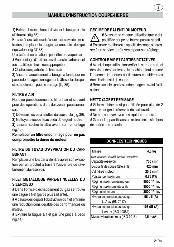
1) Extraire le capuchon et dévisser la bougie par laclé fournie (fig.36).En cas d’incrustations et d’usure excessive des élec-trodes, remplacer la bougie par une autre de typeéquivalent (fig.37-38).Un excès d’incrustations peut être provoqué par# Pourcentage d’huile excessif dans le carburant et/ou qualité de l’huile non appropriée.# Obstruction partielle du filtre à air2) Visser manuellement la bougie à fond pour nepas endommager son logement. Utiliser la clé spé-ciale seulement pour le serrage (fig.36).
FILTRE A AIRNettoyer périodiquement le filtre à air et souventpour des opérations dans des zones poussiéreu-ses.1) Dévisser l’écrou à ailettes du couvercle (fig.39).2) Nettoyer avec de l’eau et du détergent neutre.3) Laisser sécher le filtre avant son remontage(fig.40).Remplacer un filtre endommagé pour ne pascompromettre la durée du moteur.
FILTRE DU TUYAU D’ASPIRATION DU CAR-BURANTRemplacer une fois par an le filtre après son extrac-tion par un crochet à travers l’ouverture de ravi-taillement du réservoir.
FILET METALLIQUE PARE-ETINCELLES DUSILENCIEUX# Dans l’orifice d’échappement du gaz se trouveune bague à filet (partie plus saillante).# A cause des dépôts l’obstruction du filet entraîneune réduction considérable des performances dumoteur.# Extraire la bague à filet par une pince à becs(fig.41).
REGIME DE RALENTI DU MOTEUR# S’assurer à chaque utilisation que le dispositif de coupe ne tourne pas au ralenti.
# En cas de rotation du dispositif de coupe s’adres-ser à un service après-vente pour son réglage.
CONTROLE VIS ET PARTIES ROTATIVES# Avant chaque utilisation vérifier le serrage correctdes vis et des parties de la machine, tout commel’absence de criques ou d’usures considérablesdans le dispositif de coupe.# Remplacer les parties endommagées avant l’utili-sation.
NETTOYAGE ET REMISAGE# Si la machine n’est pas utilisée pour plus de 2mois, vidanger le réservoir du carburant.# Ne pas nettoyer avec des liquides agressifs.# Garder l’appareil dans un milieu sec et sûr, horsde portée des enfants.
DONNEES TECHNIQUES
Masse 4,5 kg (sans carburant – dispositif de coupe – protection)
Capacité réservoir 700 cm3
Dispositif de coupe (tête à fils) 420 mm Cylindrée moteur 25,5 cm3
Puissance maximum 0,75 KW Régime maximum du moteur 9500 1/min. Régime maximum tête à fils 9500 1/min. Régime minimum 2800 1/min. Niveau de pression acoustique 98 dB (A)
LpA av (EN 7917) Niveau de pression acoustique 108 dB (A)
LwA av (ISO 19884) Niveau vibrations max (ISO 7916) 9,5 m/s2

22/012
D
RASENTRIMMERSBEDIENUNGSANLEITUNG
1. AN UNSERE KUNDENWir möchten uns für Ihre Kaufentscheidungbedanken. Bei der Herstellung unseresRASENTRIMMERS GTL 26 haben wir zu Ihrempersönlichen Schutz die geltendenSicherheitsnormen angewandt.
Diese Anleitung macht Sie mit der Montage, demAnschluß sowie der Benutzung und Wartung IhresRASENTRIMMERS GTL 26 vertraut, damit Sieseine Vorzüge auf lange Zeit genießen können.
FÜR EIN BESSERES VERSTÄNDNISAlle Abbildungen zur Montagebefinden sich in der
Deckblattumschlagklappe.Diese während des Durchlesens derMontageanleitungen aufschlagen.
Bei Kundendienstleistungen und Reparaturenwenden Sie sich bitte an Ihren Händler bzw. aneine autorisierte Servicestelle..
2. WESENTLICHESICHERHEITSVORKEHRUNGEN
ALLGEMEINE NORMEN
HINWEISE:A1 – Die Anwendung des RASEN-TRIMMERS erfordert die Einhaltungder Sicherheitsnormen.A2 – Alle Benützer des RASEN-TRIMMERS müssen zuerst dieBedienungs- und Wartungsanleitungaufmerksam durchlesen und sich mit denSteuerungen für einen richtigen Betriebdes Geräts vertraut machen.A2.1 - Dieses Handbuch zum späte-ren Nachschlagen aufbewahren.A3 – Kindern und Personen, die diehier stehenden Anweisungen nicht ken-
nen, ist die Anwendung des RASEN-TRIMMERS untersagt.
GEFAHR:A4 – Auf das von der Schnittvorrichtungprojizierte Material aufpassen.A5 – In der Nähe von Personen, Tie-ren oder Gegenständen darf derRasentrimmer weder gestartet nochbenützt werden.Während des Betriebs ist ein Mindest-abstand von 15 m zwischen der Ma-schine und anderen Personen emp-fohlen.A6 – Für Verletzungen an anderenPersonen oder Gegenständen oder fürGefahren haftet der Bediener.
ANWENDUNG:B1 – Den RASENTRIMMER nur zumSchneiden von Gras und Unkraut ver-wenden.Das Gerät darf nicht für andere Zwek-ke angewendet werden.B2 – Eine für die Anwendung desRASENTRIMMERS passende Klei-dung und Schutzausrüstung tragen.Während der Benützung ist anliegen-de und keine lose Kleidung zu tragen.B3 – Zugelassene Schutzbrillen oderVisiere tragen.B3.1 – Zugelassenen Ohrenschutzgegen Lärm tragen.B3.2 – Besteht die Gefahr fallenderGegenstände ist ein Schutzhelm aufzu-setzen.B4 – Widerstandsfähige Schuhe mitrutschfesten Sohlen tragen.B5 – Widerstandsfähige Handschuhetragen.B6 – Die Benützer des RASEN-TRIMMERS müssen körperlich gut inForm sein. Bei Müdigkeit, Übelkeit undunter Einfluß von Alkohol oder ande-ren Drogen darf der RASEN-

23/012
D
RASENTRIMMERSBEDIENUNGSANLEITUNG
TRIMMER nicht benützt werden.B7 - ACHTUNG Die Abgase sind giftigund wirken erstickend. Bei Einatmenkönnen sie auch tödliche Auswirkun-gen haben. Der Motor darf in geschlos-senen oder wenig belüfteten Räumennicht in Betrieb genommen werden.B8 – Die verlängerte Anwendung desGeräts kann Durchblutungsstörungenin den Händen verursachen (Weiße-Finger-Krankheit), die auf dieVibrationen zurückzuführen sind.Folgende können die Faktoren sein,die das Erscheinen der Störungen be-einflussen:- Persönliche Neigung desBedieners zur schwachenDurchblutung der Hände.- Anwendung des Geräts beiniedrigen Temperaturen (daherwerden warme Handschuheempfohlen).- Lange Anwendungszeit ohneUnterbrechungen (die Anwendung mitEinlegen von Pausen ist empfohlen).- Bei Verspüren von Kribbeln undGefühllosigkeit wird das Aufsucheneines Arztes empfohlen.B8.1 – Das Gerät immer mit beidenHänden halten.Mit den Beinen eine feste und sicherePosition einnehmen.B8.2 – Der Rasentrimmer ist so aus-gelegt, um vom Bediener auf der rech-ten Seite verwendet zu werden (sieheAbb. 20).Den hinteren Griff (mit Steuerungen)mit der rechten Hand und den Vorder-griff mit der linken Hand festhalten.B9 - ACHTUNG! Das Benzin und sei-ne Dämpfe sind leichtentzündlich.BRANDWUNDEN- UND BRANDGE-FAHR.
B9.1 – Den Motor vor dem Nachtan-ken abstellen.B9.2 – Während dem Auftanken nichtrauchen.B9.3 – Den eventuell verschüttetenTreibstoff trocknen. Den Motor an ei-nem von der Auftankstelle entfernten Ortstarten.B9.4 – Sich vergewissern, dass der Dek-kel des Tankbehälters gut verschlossenist. Auf eventuelle Leckstellen achten.B10 – Mit dem Gerät wird eineSCHUTZABDECKUNG DERSCHNITTVORRICHTUNG (Abb.1Det.14-15) geliefert, die vor der An-wendung montiert werden muß (sieheMontageanleitung).Ohne dieser Schutzabdeckung darf dasGerät weder gestartet noch verwendetwerden.B10.1 - GEFAHR! Durch die Schnitt-vorrichtung verursachte Wunden; Pro-jizieren von Material auf den Bediener.Die Schutzabdeckung nicht abändern.Eine schadhafte Schutzabdeckung darfnur mit einem Original-Ersatzteil aus-getauscht werden.B10.2 – GEFAHR! Keinen Draht in denSchnittkopf montieren.B10.3 – Die BLOCKIERVOR-RICHTUNG DER GASHEBELS-TEUERUNG (siehe Abb. 1 Det. 12):verhindert einen unabsichtlichen An-trieb des Gashebels.B10.4 - SCHALTER (ON/OFF) zumAbstellen des Motors (Abb.1 Det.10).GEFAHR! Achtung! Die Schnittvor-richtung dreht sich noch für eine ge-wisse Zeit nach dem Ausschalten(Schalter auf Position “OFF”) weiter. Diezwei Griffe bis zum vollständigen Still-stand festhalten. Siehe Kapitel ANLAUFUND STOP.
24/012
3. BESCHREIBUNG DERMASCHINENTEILE
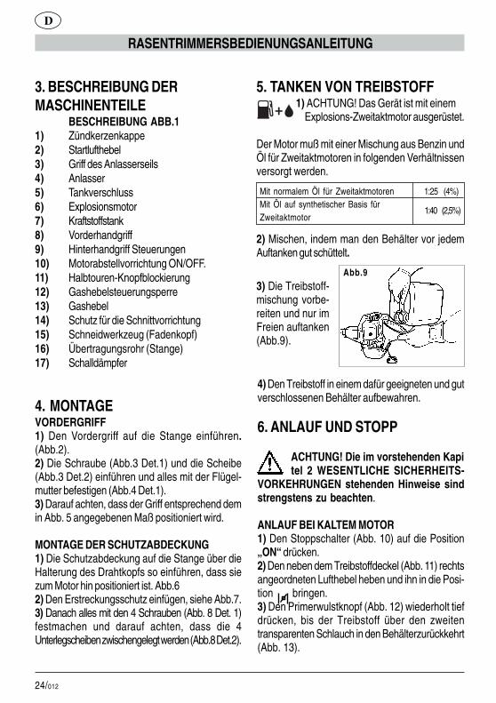
BESCHREIBUNG ABB.11) Zündkerzenkappe2) Startlufthebel3) Griff des Anlasserseils4) Anlasser5) Tankverschluss6) Explosionsmotor7) Kraftstoffstank8) Vorderhandgriff9) Hinterhandgriff Steuerungen10) Motorabstellvorrichtung ON/OFF.11) Halbtouren-Knopfblockierung12) Gashebelsteuerungsperre13) Gashebel14) Schutz für die Schnittvorrichtung15) Schneidwerkzeug (Fadenkopf)16) Übertragungsrohr (Stange)17) Schalldämpfer
4. MONTAGEVORDERGRIFF1) Den Vordergriff auf die Stange einführen.(Abb.2).2) Die Schraube (Abb.3 Det.1) und die Scheibe(Abb.3 Det.2) einführen und alles mit der Flügel-mutter befestigen (Abb.4 Det.1).3) Darauf achten, dass der Griff entsprechend demin Abb. 5 angegebenen Maß positioniert wird.
MONTAGE DER SCHUTZABDECKUNG1) Die Schutzabdeckung auf die Stange über dieHalterung des Drahtkopfs so einführen, dass siezum Motor hin positioniert ist. Abb.62) Den Erstreckungsschutz einfügen, siehe Abb.7.3) Danach alles mit den 4 Schrauben (Abb. 8 Det. 1)festmachen und darauf achten, dass die 4Unterlegscheiben zwischengelegt werden (Abb.8 Det.2).
5. TANKEN VON TREIBSTOFF 1) ACHTUNG! Das Gerät ist mit einem Explosions-Zweitaktmotor ausgerüstet.
Der Motor muß mit einer Mischung aus Benzin undÖl für Zweitaktmotoren in folgenden Verhältnissenversorgt werden.
D
RASENTRIMMERSBEDIENUNGSANLEITUNG
1:40 (2,5%)
Abb.9
Mit normalem Öl für Zweitaktmotoren 1:25 (4%) Mit Öl auf synthetischer Basis für Zweitaktmotor
2) Mischen, indem man den Behälter vor jedemAuftanken gut schüttelt.
3) Die Treibstoff-mischung vorbe-reiten und nur imFreien auftanken(Abb.9).
4) Den Treibstoff in einem dafür geeigneten und gutverschlossenen Behälter aufbewahren.
6. ANLAUF UND STOPP
ACHTUNG! Die im vorstehenden Kapitel 2 WESENTLICHE SICHERHEITS-
VORKEHRUNGEN stehenden Hinweise sindstrengstens zu beachten.
ANLAUF BEI KALTEM MOTOR1) Den Stoppschalter (Abb. 10) auf die Position„ON“ drücken.2) Den neben dem Treibstoffdeckel (Abb. 11) rechtsangeordneten Lufthebel heben und ihn in die Posi-tion bringen.3) Den Primerwulstknopf (Abb. 12) wiederholt tiefdrücken, bis der Treibstoff über den zweitentransparenten Schlauch in den Behälterzurückkehrt(Abb. 13).
25/012
D
RASENTRIMMERSBEDIENUNGSANLEITUNG
Abb.11
Abb.12 Abb.13
Abb.14 Abb.15
Abb.16
Abb.17
Abb.18 Abb.19
�
�
�
�
�
�
� �
�
1
2
1
Abb.10
�
ON
OFF
ON
OFF
ANLAUF MIT WARMEM MOTORDerselbe Vorgang wie beim kalten Motor, aber denLufthebel nach unten senken (siehe Abb.18).
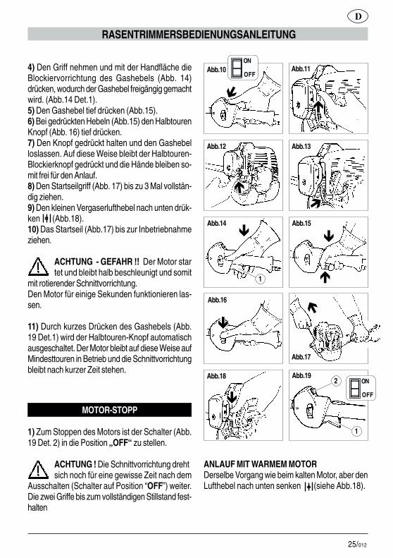
4) Den Griff nehmen und mit der Handfläche dieBlockiervorrichtung des Gashebels (Abb. 14)drücken, wodurch der Gashebel freigängig gemachtwird. (Abb.14 Det.1).5) Den Gashebel tief drücken (Abb.15).6) Bei gedrückten Hebeln (Abb.15) den HalbtourenKnopf (Abb. 16) tief drücken.7) Den Knopf gedrückt halten und den Gashebelloslassen. Auf diese Weise bleibt der Halbtouren-Blockierknopf gedrückt und die Hände bleiben so-mit frei für den Anlauf.8) Den Startseilgriff (Abb. 17) bis zu 3 Mal vollstän-dig ziehen.9) Den kleinen Vergaserlufthebel nach unten drük-ken (Abb.18).10) Das Startseil (Abb.17) bis zur Inbetriebnahmeziehen.
ACHTUNG - GEFAHR !! Der Motor startet und bleibt halb beschleunigt und somit
mit rotierender Schnittvorrichtung.Den Motor für einige Sekunden funktionieren las-sen.
11) Durch kurzes Drücken des Gashebels (Abb.19 Det.1) wird der Halbtouren-Knopf automatischausgeschaltet. Der Motor bleibt auf diese Weise aufMindesttouren in Betrieb und die Schnittvorrichtungbleibt nach kurzer Zeit stehen.
MOTOR-STOPP
1) Zum Stoppen des Motors ist der Schalter (Abb.19 Det. 2) in die Position „OFF“ zu stellen.
ACHTUNG ! Die Schnittvorrichtung drehtsich noch für eine gewisse Zeit nach dem
Ausschalten (Schalter auf Position “OFF”) weiter.Die zwei Griffe bis zum vollständigen Stillstand fest-halten
26/012
D
RASENTRIMMERSBEDIENUNGSANLEITUNG
7. ANWENDUNGANWENDUNG DES RASENTRIMMERS1) Das Gerät entsprechend der Abb. 20 auf derrechten Seite halten.
EINSTELUNG DER SCHNITTFADENLÄNGEDer Fadenkopf ist halbautomatisch und ermöglichtdie richtige Länge der Fäden einzustellen, ohnedabei den Motor ausschalten zu müssen.Bevor sich der Faden bis auf seine halbe Längeabgenützt hat, ist der Kopf kurz auf den Boden zudrücken und der Motor dabei auf Hochgeschwin-digkeit zu halten.Durch diesen Vorgang wickelt sich der Faden (durchden Schleudereffekt) von der internen Spule ab. Diekorrekte Länge wird automatisch durch die auf derSchutzvorrichtung angebrachte Klinge eingestellt.
SCHNEIDEN VON GRASDen Schnittkopf parallel zum Boden halten, vor-wärtsgehen und dabei nach rechts und links schwin-gen (Abb. 23). Den Motor auf vollen Touren, umeinen reinen Schnitt zu erzielen.
HINDERNISSE, PFLANZEN, ZÄUNE UM-SCHNEIDENDas Hindernis mit dem Fadenende (Abb. 23) strei-fen. Durch Neigen des Kopfs (Abb. 22) kann dieSchnittwirkung verbessert werden. Damit die Fä-den nicht kaputt gehen, darf mit dem Schnittkopf anden Hindernissen nicht angestoßen werden. Reißtein Faden, ist dieser gemäß der Beschreibung fürden Wechsel des Fadens zu ersetzen.
8. FADENWECHSELMontagemöglichkeiten: es kann eine neue Spulekomplett mit Faden montiert oder der neue Fadenauf die Originalspule aufgewickelt werden.A) Verwenden Sie einen Faden mit Durchmesser 2mm aus Kunststoff, speziell für Rasentrimmer mitFaden.
ACHTUNG GEFAHR! KEINESFALLSDARF METALLDRAHT VERWEDETWERDEN
B) AUSBAU DER SPULE1) Den Kugelgriff gegen den Uhrzeigersinn ab-schrauben (Abb.24).2) Die Spule vom Kopfkörper abziehen (Abb.25-26).3) Den Körper innen (Abb.27) sorgfältig reinigenund den Verschleißzustand der inneren Zähneüberprüfen (Abb. 28). Bei deutlichen Verschleißer-scheinungen den kompletten Kopf ersetzen.
C) FADENAUFWICKELNEinen nicht mehr als 10 m langen Faden verwenden.1) Die zwei Enden des Fadens in die zwei Löcherder Spule einführen. Sie auf der entgegengesetz-ten Seite herausziehen und miteinander verbinden(Abb.29).2) Die zwei verbundenen Fadenlängen auf dieSpule wickeln und die auf der Spule eingeprägtePfeilrichtung beachten (Abb. 30).3) Um die Wiedereinführung der Spule in den Kör-per zu erleichtern, die beiden Fadenenden in denbeiden dafür vorgesehenen Schlitzen befestigen(Abb. 31).
D) WIEDEREINBAU DER SPULE1) Die zwei Enden durch den Fadendurchgangführen (Abb.32-33).2) In den Kopf die Feder und danach die Spuleeinführen.3) Die Fadenenden fest ziehen, damit sie sich vonden Schlitzen abziehen (Abb.34).4) Den Kugelgriff im Uhrzeigersinn fest anschrau-ben (Abb. 35). Abgenützte Kugelgriffe ersetzen.
9. WARTUNGKERZEMindestens einmal jährlich oder bei Störungen wäh-rend des Startens ist der Zustand der Zündkerze zuüberprüfen. Abwarten, bis der Motor kalt ist.
27/012
D
RASENTRIMMERSBEDIENUNGSANLEITUNG
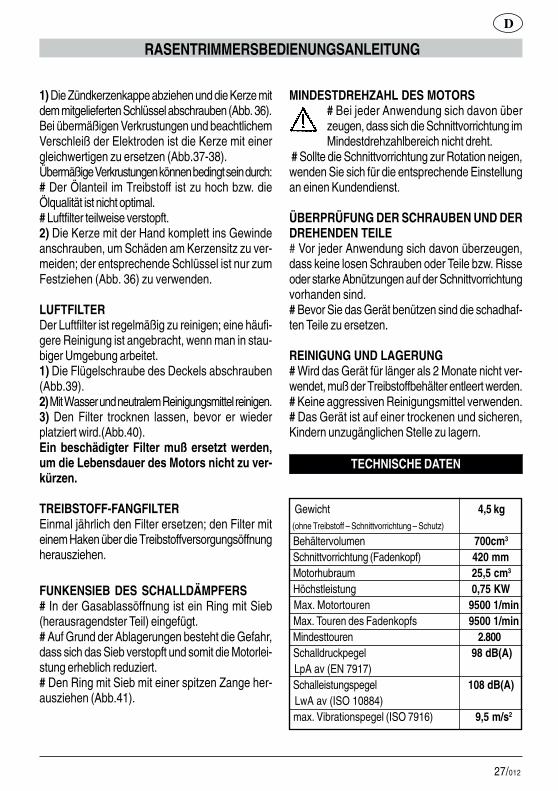
1) Die Zündkerzenkappe abziehen und die Kerze mitdem mitgelieferten Schlüssel abschrauben (Abb. 36).Bei übermäßigen Verkrustungen und beachtlichemVerschleiß der Elektroden ist die Kerze mit einergleichwertigen zu ersetzen (Abb.37-38).Übermäßige Verkrustungen können bedingt sein durch:# Der Ölanteil im Treibstoff ist zu hoch bzw. dieÖlqualität ist nicht optimal.# Luftfilter teilweise verstopft.2) Die Kerze mit der Hand komplett ins Gewindeanschrauben, um Schäden am Kerzensitz zu ver-meiden; der entsprechende Schlüssel ist nur zumFestziehen (Abb. 36) zu verwenden.
LUFTFILTERDer Luftfilter ist regelmäßig zu reinigen; eine häufi-gere Reinigung ist angebracht, wenn man in stau-biger Umgebung arbeitet.1) Die Flügelschraube des Deckels abschrauben(Abb.39).2) Mit Wasser und neutralem Reinigungsmittel reinigen.3) Den Filter trocknen lassen, bevor er wiederplatziert wird.(Abb.40).Ein beschädigter Filter muß ersetzt werden,um die Lebensdauer des Motors nicht zu ver-kürzen.
TREIBSTOFF-FANGFILTEREinmal jährlich den Filter ersetzen; den Filter miteinem Haken über die Treibstoffversorgungsöffnungherausziehen.
FUNKENSIEB DES SCHALLDÄMPFERS# In der Gasablassöffnung ist ein Ring mit Sieb(herausragendster Teil) eingefügt.# Auf Grund der Ablagerungen besteht die Gefahr,dass sich das Sieb verstopft und somit die Motorlei-stung erheblich reduziert.# Den Ring mit Sieb mit einer spitzen Zange her-ausziehen (Abb.41).
MINDESTDREHZAHL DES MOTORS# Bei jeder Anwendung sich davon überzeugen, dass sich die Schnittvorrichtung imMindestdrehzahlbereich nicht dreht.
# Sollte die Schnittvorrichtung zur Rotation neigen,wenden Sie sich für die entsprechende Einstellungan einen Kundendienst.
ÜBERPRÜFUNG DER SCHRAUBEN UND DERDREHENDEN TEILE# Vor jeder Anwendung sich davon überzeugen,dass keine losen Schrauben oder Teile bzw. Risseoder starke Abnützungen auf der Schnittvorrichtungvorhanden sind.# Bevor Sie das Gerät benützen sind die schadhaf-ten Teile zu ersetzen.
REINIGUNG UND LAGERUNG# Wird das Gerät für länger als 2 Monate nicht ver-wendet, muß der Treibstoffbehälter entleert werden.# Keine aggressiven Reinigungsmittel verwenden.# Das Gerät ist auf einer trockenen und sicheren,Kindern unzugänglichen Stelle zu lagern.
TECHNISCHE DATEN
Gewicht 4,5 kg (ohne Treibstoff – Schnittvorrichtung – Schutz)
Behältervolumen 700cm3
Schnittvorrichtung (Fadenkopf) 420 mm Motorhubraum 25,5 cm3
Höchstleistung 0,75 KW Max. Motortouren 9500 1/min Max. Touren des Fadenkopfs 9500 1/min Mindesttouren 2.800 Schalldruckpegel 98 dB(A) LpA av (EN 7917) Schalleistungspegel 108 dB(A) LwA av (ISO 10884) max. Vibrationspegel (ISO 7916) 9,5 m/s2
28/012
NL
HANDLEIDING GRASMAAIER
toekomstige raadpleging.A3 - Sta het gebruik van de GRAS-MAAIER niet toe aan kinderen en per-sonen, die niet geheel op de hoogtezijn van deze instructies.
GEVAAR:A4 - Wees bedacht op materiaal dat uitde maai-inrichting wegschiet.A5 - Stel de grasmaaier niet in werkingen gebruik deze niet in de nabijheidvan mensen, dieren of voorwerpen.Tijdens de werking wordt het aanbe-volen een minimumafstand van 15 m.aan te houden tussen de gebruiker enandere personen.A6 - De gebruiker is aansprakelijk bijongelukken, gevaar voor anderen, ofschade aan bezittingen van anderen.
GEBRUIK:B1 - Gebruik de GRASMAAIER uit-sluitend voor het maaien van gras enonkruid, dus niet voor andere doel-einden.B2 - Draag kleding en een veiligheids-uitrusting die geschikt is voor het ge-bruik van de GRASMAAIER.Draag tijdens het gebruik nauwslui-tende, niet loshangende kleding.B3 - Draag een goedgekeurdeveiligheidsbril of een gezichtsmasker.B3.1 - Draag goedgekeurde oor-bescherming tegen het lawaai.B3.2 - Draag een veiligheidshelm bijrisico op vallende voorwerpen.B4 - Draag stevige werkschoenen metanti-slipzolen.B5 - Draag stevige handschoenen.B6 - Maak alleen gebruik van deGRASMAAIER als u in goede conditiebent. GEBRUIK de GRASMAAIERNIET wanneer u vermoeid bent, zich
1. GEFELICITEERDBeste klant, wij feliciteren u met uw keuze van éénvan onze producten voor de tuin. DeGRASMAAIER GTL 26 is gebouwd volgens degeldende veiligheidsnormen ter bescherming vande consument.
In dit instructieboekje worden de verschillendehandelingen voor montage, installatie en gebruikbeschreven en geïllustreerd, evenals deonderhoudswerkzaamheden die nodig zijn om uwGRASMAAIER GTL 26 in perfecte staat van werkingte houden.
VOOR EEN BETER BEGRIPAfbeeldingen voor de montage zijnte zien op achterzijde van de
omslag aan het begin van dit boekje. Laat dezepagina’s tijdens het lezen van demontageaanwijzingen open liggen.
Voor eventuele service of reparatie van uwGRASMAAIER dient u zich tot uw winkelier of toteen erkend servicecentrum te wenden.
2. FUNDAMENTELEVEILIGHEIDSMAATREGELEN
ALGEMENE NORMEN
WAARSCHUWINGEN:A1 - Neem, bij het gebruik van deGRASMAAIER de veiligheidsnormenin acht.A2 - Lees eerst zorgvuldig de handleidingvoor gebruik en onderhoud om geheelvertrouwd te raken met de bedienings-elementen, dit ten behoeve van een cor-rect gebruik van het apparaat.A2.1 - Bewaar deze handleiding voor
29/012
NL
HANDLEIDING GRASMAAIER
niet lekker voelt of onder invloed bentvan alcohol of drugs.B7 - ATTENTIE! De uitlaatgassen zijngiftig en verstikkend. Bij inademing kun-nen ze zelfs dodelijk zijn. Laat de motorniet draaien in een gesloten en schaarsgeventileerde ruimte.B8 - Langdurig gebruik van het appa-raat kan een verstoring van de bloeds-omloop in de handen veroorzaken(ziekte van de witte vingers), die toe-geschreven wordt aan de trillingen.Factoren die van invloed kunnen zijnop deze verschijnselen zijn:- Persoonlijke aanleg van de gebrui-ker: schaarse bloedtoevoer naar dehanden.- Gebruik van het apparaat bij lage tem-peraturen (het gebruik van warmehandschoenen wordt aanbevolen).- Langdurig gebruik zonder onderbre-kingen (het wordt aanbevolen pauzesin te lassen).- Tinteling en verstijving, hierbij wordthet aanbevolen een arts te raadple-gen.B8.1 - Houd het apparaat altijd metbeide handen vast.Neem een stabiele en zekere houdingaan.B8.2 - De grasmaaier is ontworpenvoor het gebruik op de rechterheupvan de gebruiker (zie afb. 20).Houd de achterste handgreep (met debedieningen) in de rechterhand en devoorste handgreep in de linkerhand.B9 - ATTENTIE! De benzine en debenzinedampen zijn uiterst ontvlam-baar, dus gevaar voorBRANDWONDEN- EN BRAND.B9.1 - Breng de motor tot stilstand vóór
het toevoeren van brandstof.B9.2 - Rook niet tijdens de brandstof-toevoer.B9.3 - Droog de eventueel gemorstebrandstof. Stel het apparaat in werkingop grote afstand van de plaats waar debrandstoftoevoer plaatsvond.B9.4 - Overtuig u ervan dat de dopvan de tank goed vast zit.Let op eventuele lekkages.B10 - Bij het apparaat is eenBESCHERMKAP VOOR DE MAAI-INRICHTING geleverd (Afb.1 detail14-15) die vóór het gebruik gemon-teerd moet worden (zie de instructiesvoor montage).Het apparaat niet in werking stellen,noch gebruiken indien de bescherm-kap niet gemonteerd is.B10.1 - GEVAAR! Letsel ten gevolgevan aanraking met de maai-inrichtingof wegschieten van materiaal in de rich-ting van de gebruiker.Wijzig niets aan de beschermkap.Vervang de beschermkap wanneerdeze beschadigd is en gebruik hier-voor alleen originele vervangings-onderdelen.B10.2 - GEVAAR! Monteer geenmetaaldraad in de maaikop.B10.3 - De BLOKKERING VAN DEBEDIENING VAN DE VERSNELLING(zie afb.1 detail 12): voorkomt de on-vrijwillige activering van de hendel vande versnelling.B10.4 - SCHAKELAAR (ON/OFF)voor stilstand van de motor (afb. 1 de-tail 10).GEVAAR! Attentie, de maai-inrichtingblijft gedurende een bepaalde tijd door-gaan met draaien, ook nadat de scha-
30/012
kelaar op “OFF” gezet is. Houd debeide handgrepen stevig vast tot hetapparaat geheel tot stilstand is geko-men. Zie het hoofdstuk STARTEN ENSTILSTAND.
3. BESCHRIJVING MACHINEDELENBESCHRIJVING Afb. 1
1) Kapje van de bougie2) Luchthendeltje3) Handgreep van de startkabel4) Starter5) Dop brandstoftank6) Verbrandingsmotor7) Brandstoftank8) Voorste handgreep9) Achterste handgreep met bediening10) Stopinrichting van de motor ON/OFF.11) Blokkering halve versneller12) Blokkering van de bediening van de
versnellingshendel13) Versnellingshendel14) Beschermkap maai-inrichting15) Maai-inrichting (kop met draden)16) Transmissieleiding (stang)17) Geluiddemper
4. MONTAGE VOORSTEHANDGREEP1) Plaats de voorste handgreep op de stang (afb. 2).2) Breng de schroef (afb. 3 detail 1) en de borgring(afb. 3 detail 2) aan en zet alles vast met de vleugel-moer (afb. 4 detail 1).3) Let op dat u de handgreep op de door afb. 5aangegeven maat plaatst.
MONTAGE BESCHERMKAP1) Plaats de beschermkap op de stang, boven deondersteuning van de kop met draden, en in derichting van de motor, afb. 6.2) Breng het verlengstuk van de beschermkap aan,zie afb. 7.
3) Zet alles vast met de 4 schroeven (afb. 8 detail 1)en let er op de 4 borgringen aan te brengen tussenschroeven en materiaal (afb. 8 detail 2).
5. BRANDSTOFTOEVOER 1) ATTENTIE! Het apparaat is uit gerust met een tweetakt verbrandingsmotor.
De motor moet gevoed worden met een mengselvan benzine en olie voor tweetakt motoren, waarbijde volgende percentages aangehouden moetenworden:
Gewone olie voor tweetakt motoren 1:25 (4%) Olie op synthetische basis voor tweetakt motoren 1:40 (2,5%)
2) Meng de inhoud van de houder door deze flinkte schudden vóór iedere brandstoftoevoer.
NL
HANDLEIDING GRASMAAIER
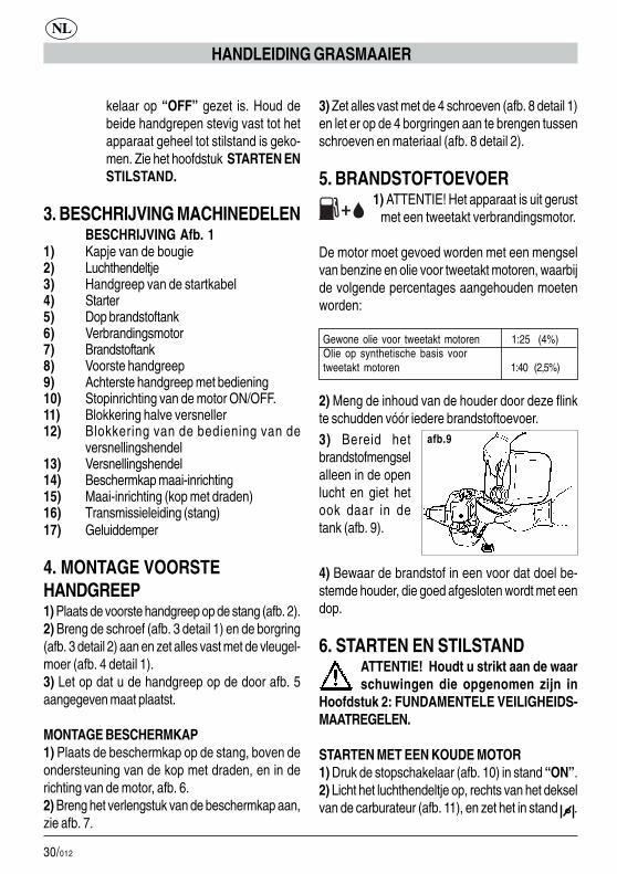
afb.93) Bereid hetbrandstofmengselalleen in de openlucht en giet hetook daar in detank (afb. 9).
4) Bewaar de brandstof in een voor dat doel be-stemde houder, die goed afgesloten wordt met eendop.
6. STARTEN EN STILSTANDATTENTIE! Houdt u strikt aan de waarschuwingen die opgenomen zijn in
Hoofdstuk 2: FUNDAMENTELE VEILIGHEIDS-MAATREGELEN.
STARTEN MET EEN KOUDE MOTOR1) Druk de stopschakelaar (afb. 10) in stand “ON”.2) Licht het luchthendeltje op, rechts van het dekselvan de carburateur (afb. 11), en zet het in stand .

31/012
NL
HANDLEIDING GRASMAAIER
3) Druk het primerbolletje enkele malen helemaal in(afb. 12), tot de brandstof door de transparante lei-ding (fig. 13) in de tank terugkeert.4) Pak de handgreep vast en druk met de hand-palm op de blokkering van de versnellingshendel,waardoor de beweging hiervan gedeblokkeerdwordt (afb.14 detail 1).5) Druk de versnellingshendel helemaal in (afb.15).6) Terwijl u de hendel ingedrukt houdt (afb.15),drukt u de knop voor halve snelheid helemaal in(afb.16).7) Terwijl u deze knop ingedrukt houdt, laat u dehendel van de versnelling los.Op deze wijze blijft de blokkeerknop voor halvesnelheid ingeschakeld, en heeft u beide handen vrijvoor het starten.8) Trek tot 3 keer toe de handgreep van de start-kabel helemaal uit (afb. 17).9) Duw het luchthendeltje van de carburateur om-laag (afb.18).10) Trek aan de startkabel (afb.17) tot de motoraanslaat.
ATTENTIE - GEVAAR !! De motor gaatvan start en draait op halve snelheid. De
maai-inrichting draait dus!!Laat de motor enkele seconden draaien.
11) Druk kort op de versnellingshendel (afb. 19detail 1). De knop voor halve snelheid wordt nuautomatisch uitgeschakeld. De motor blijft draaienbij minimumsnelheid en de maai-inrichting komt nakorte tijd tot stilstand.
STILSTAND MOTOR
1) Om de motor tot stilstand te brengen zet u deschakelaar (afb. 19 detail 2) op “OFF”.
ATTENTIE! De maai-inrichting blijft gedurende een bepaalde tijd doorgaan met
draaien, ook nadat u de schakelaar op “OFF” ge-zet heeft. Houd de handgrepen stevig met beidehanden vast tot de motor geheel tot stilstand is geko-men.STARTEN MET EEN WARME MOTORGa te werk als bij een koude motor, maar met om-laag gedrukt luchthendeltje (zie afb. 18).
afb.11
afb.12 afb.13
afb.14 afb.15
afb.16
afb.17
afb.18 afb.19
�
�
�
�
�
�
� �
�
1
2
1
afb.10
�
ON
OFF
ON
OFF
32/012
NL
HANDLEIDING GRASMAAIER
7. GEBRUIKHOE DE GRASMAAIER TE GEBRUIKEN1) Houd het apparaat op uw rechter heup, zoals opafb. 20 getoond wordt.
AFSTELLING VAN DE LENGTE VAN DE MAAI-DRAADDe kop met draden is van het halfautomatische typeen maakt het mogelijk de juiste lengte van de dra-den in te stellen, zonder de motor tot stilstand telaten komen.Als de maaidraad versleten raakt tot halverwegede lengte, drukt u de kop kort op het terrein, terwijlu de motor bij hoge snelheid laat draaien (afb.21).Hierdoor wordt de draad afgewikkeld (door hetcentrifuge-effect) van de interne spoel. De juistelengte wordt automatisch ingesteld door het mesjedat voor dat doel op de beschermkap geplaatst is.
GRASMAAIENHoud de maaikop parallel aan het terrein en be-weeg u voort terwijl u het apparaat van rechts naarlinks beweegt (afb. 23). Houd de motor op vollesnelheid voor het verrichten van een scherpesnede.
MAAIEN ROND OBSTAKELS, PLANTEN, HEK-KENRaak het obstakel vluchtig aan met het uiteinde vande draad (afb. 23). De inclinatie van de kop (afb.22) kan de efficiëntie van de snede verbeteren.Stoot niet met de maaikop tegen de obstakels; uvoorkomt zo dat de draden breken.Ga bij het breken van de draden te werk als bij eenvervanging.
8. VERVANGING VAN DE DRAADMonteer een compleet nieuwe spoel met draad ofwikkel een nieuwe draad om de oorspronkelijkespoel.A) gebruik plastic draad met een diameter van 2mm, dat speciaal bestemd is voor grasmaaiers metdraden.
ATTENTIE, GEVAAR! GEBRUIK ABSOLUUT GEEN METAALDRAAD.
B) DEMONTAGE SPOEL1) Schroef de knop los, tegen de wijzers van deklok in (afb.24).2) Trek de spoel uit de behuizing van de kop (afb.25-26).3) Reinig zorgvuldig de binnenkant van de behui-zing (afb. 27) en controleer de mate van slijtage vande interne tanden (afb. 28), in geval van overdui-delijke slijtage vervangt u de gehele kop.
C) OMWIKKELING VAN DE DRAADGebruik een draadlengte van niet meer dan 10 m.1) Steek de twee uiteinden van de draad in de tweegaten van de spoel. Trek aan de tegenoverliggendekant aan de twee uiteinden en voeg ze samen(afb.29).2) Wikkel de twee stukken draad gezamenlijk om despoel, en volg de richting van de pijl die op de spoelzelf afgedrukt staat (afb. 30).3) Ter vereenvoudiging van het terugplaatsen vande spoel in de behuizing steekt u de twee uiteindenvan de draad in de daarvoor bestemde gleuven(afb. 31).
D) OPNIEUW MONTEREN VAN DE SPOEL1) Geleid de twee uiteinden langs de draadgeleiders(afb. 32-33).2) Steek de veer in de kop en plaats vervolgens despoel.3) Trek flink aan de twee uiteinden van de draadzodat ze uit de gleuven getrokken worden (afb. 34).4) Draai de knop weer vast in de richting van dewijzers van de klok (afb. 35). Vervang de knopwanneer deze versleten is.
9. ONDERHOUDBOUGIEMinstens eenmaal per jaar, of bij startproblemen,controleert u de staat van de startbougie. Wachteerst tot de motor afgekoeld is alvorens u tot con-trole overgaat.

33/012
NL
HANDLEIDING GRASMAAIER
1) Verwijder het kapje en schroef de bougie los metde bijgeleverde sleutel (afb. 36).Bij overmatige vuilaanslag en aanzienlijke slijtagevan de elektroden dient u de bougie te vervangendoor een van een gelijksoortig type (afb. 37-38).Een overmatige vuilaanslag kan toe te schrijvenzijn aan:# Overmatig percentage olie in de brandstof en/ofongeschikte kwaliteit van de olie.# Filter gedeeltelijk verstopt.2) Schroef de bougie met de hand los tot het eindevan de schroefdraad om schade aan de zitting tevoorkomen. Gebruik de betreffende sleutel alleenvoor het vastzetten (afb. 36).
LUCHTFILTERReinig regelmatig het luchtfilter; reinig het vakerwanneer u in een stofrijke omgeving werkt.1) Schroef de vleugelschroef los van het deksel(afb.39).2) Reinig het filter met water en een neutraalreinigingsproduct.3) Laat het filter drogen voordat u het terugplaatst(afb. 40).Vervang het filter wanneer het beschadigd is,zodat u de levensduur van de motor niet ophet spel zet.
AANZUIGFILTER VAN DE BRANDSTOFVervang tenminste eenmaal per jaar het filter, doorhet met een haak door de vulopening van de tanknaar buiten te halen.
ANTI-VONKNET VAN DE GELUIDDEMPER# In het uitlaatgat voor het gas is een ring gesto-ken met een net (het gedeelte dat het meest naarbuiten steekt).# Dit net vertoont de neiging om door aanslagverstopt te raken, waardoor de prestaties van demotor aanzienlijk minder worden.# Verwijder de ring met het net met behulp van eenplatbektang (fig.41).
MINIMUMSNELHEID VAN DE MOTOR# Controleer bij ieder gebruik of de maai-inrichting niet draait wanneer de motor bij
minimumsnelheid draait.# Vertoont de maai-inrichting de neiging tot draaienbij minimumsnelheid, richt u zich dan tot een service-dienst om het apparaat goed af te laten stellen.
CONTROLE SCHROEVEN EN DRAAIENDEDELEN# Vóór ieder gebruik dient u te controleren of ergeen schroeven of onderdelen loszitten en of demaai-inrichting geen barsten of aanzienlijke slijtagevertoont.# Vervang de beschadigde delen voordat u hetapparaat opnieuw gebruikt.
REINIGING EN OPSLAG# Gebruikt u het apparaat langer dan 2 maandenniet, dan dient u de brandstoftank te legen.# Niet reinigen met agressieve vloeistoffen.# Bewaar het apparaat op een droge en veiligeplek die niet toegankelijk is voor kinderen.
TECHNISCHE GEGEVENS
Massa 4,5 Kg (zonder brandstof – maai-inrichting - beschermkap)
Inhoud tank 700 cm³ Maai-inrichting (kop met draden) 420 mm Cilinderinhoud motor 25,5 cm³ Maximum vermogen 0,75 KW Maximum toerental motor 9.500 1/min Maximum toerental kop met draden 9.500 1/min Minimum toerental 2.800 1/min Niveau akoestische druk 98 dB (A) LpA av (EN 7917) Niveau akoestische druk 108 dB (A) LwA av (ISO 10884) Max. niveau trillingen (ISO 7916) 9,5 m/s²
34/012
E
MANUAL DE INSTRUCCIONES CORTACÉSPED
mandos para poder emplear el apara-to de forma correcta.A2.1 - Guardar este manual parapoderlo utilizar en el futuro.A3 - Impedir la utilización del CORTA-CÉSPED por los niños y las personasque no conozcan completamente estasinstrucciones.
PELIGRO:A4 - Prestar atención al material pro-yectado por el dispositivo de corte.A5 - No arrancar ni utilizar el cortacés-ped en las cercanías de personas, ani-males o cosas.Durante el funcionamiento, se reco-mienda mantener una distancia mínimade 15 m entre la máquina y otras per-sonas.A6 - El operador es responsable encaso de peligros o accidentes ocasio-nados a otras personas o a sus cosas.
UTILIZACIÓN:B1 - Utilizar el CORTACÉSPED sola-mente para cortar hierba y maleza.No emplear el aparato para otros moti-vos.B2 - Llevar prendas de vestir y unequipo de seguridad adecuados parala utilización del CORTACÉSPED.Durante la utilización, llevar prendasde vestir ceñidas y no desatadas.B3 - Llevar gafas de protección o vise-ras homologadas.B3.1 - Llevar auriculares de protec-ción contra el ruido homologados.B3.2 - Llevar el casco de protecciónen caso de riesgo de caída de objetos.B4 - Calzar zapatos resistentes consuelas no resbaladizas.B5 - Llevar guantes resistentes.B6 - Las personas que utilizan el COR-TACÉSPED deben estar en buena for-
1. CONGRATULACIONESEstimado cliente, deseamos congratularnos con Ud.por haber elegido un nuestro producto para eljardín.El CORTACÉSPED GTL 26 ha sido fabricadoteniendo en cuenta las normas de seguridadvigentes para la tutela del consumidor.
En este manual se describen y representan lasdiferentes operaciones de instalación, de uso y lasintervenciones de mantenimiento necesarias paramantener su CORTACÉSPED GTL 26 en perfectascondiciones de funcionamiento.
PARA FACILITAR LA LECTURALas figuras correspondientes a lainstalación de la máquina se
encuentran en la solapa de la cubierta, al principiode este librete. Mantenga esas páginas abiertasdurante la lectura de las instrucciones de instalacióny de uso.
En caso de que su CORTACÉSPED necesiteasistencia o reparación, le rogamos que se dirija anuestro vendedor o a un centro de asistenciaautorizado.
2. PRECAUCIONES FUNDAMENTA-LES DE SEGURIDAD
NORMAS GENERALES
ADVERTENCIAS:A1 - La utilización del CORTACÉSPEDrequiere el respeto de las normas deseguridad.A2 - Antes de utilizar el CORTACÉS-PED se debe leer con cuidado el ma-nual de instrucciones y mantenimientoy familiarizarse perfectamente con los
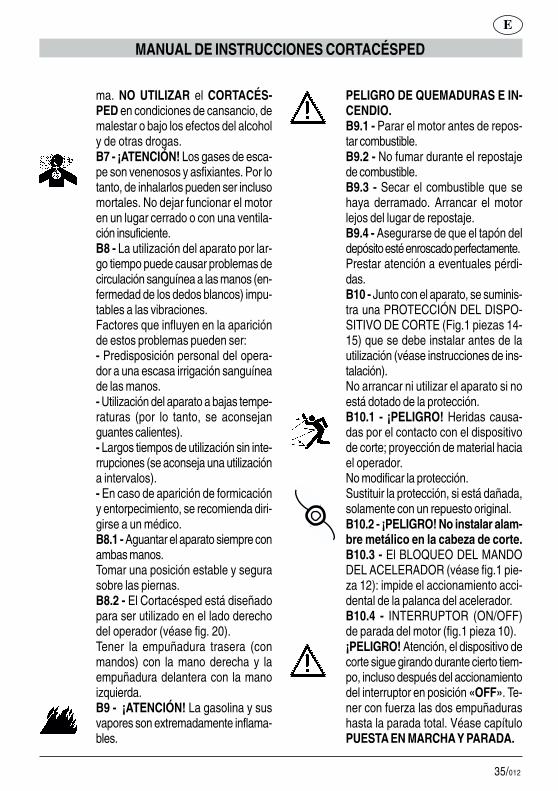
35/012
E
MANUAL DE INSTRUCCIONES CORTACÉSPED
ma. NO UTILIZAR el CORTACÉS-PED en condiciones de cansancio, demalestar o bajo los efectos del alcoholy de otras drogas.B7 - ¡ATENCIÓN! Los gases de esca-pe son venenosos y asfixiantes. Por lotanto, de inhalarlos pueden ser inclusomortales. No dejar funcionar el motoren un lugar cerrado o con una ventila-ción insuficiente.B8 - La utilización del aparato por lar-go tiempo puede causar problemas decirculación sanguínea a las manos (en-fermedad de los dedos blancos) impu-tables a las vibraciones.Factores que influyen en la apariciónde estos problemas pueden ser:- Predisposición personal del opera-dor a una escasa irrigación sanguíneade las manos.- Utilización del aparato a bajas tempe-raturas (por lo tanto, se aconsejanguantes calientes).- Largos tiempos de utilización sin inte-rrupciones (se aconseja una utilizacióna intervalos).- En caso de aparición de formicacióny entorpecimiento, se recomienda diri-girse a un médico.B8.1 - Aguantar el aparato siempre conambas manos.Tomar una posición estable y segurasobre las piernas.B8.2 - El Cortacésped está diseñadopara ser utilizado en el lado derechodel operador (véase fig. 20).Tener la empuñadura trasera (conmandos) con la mano derecha y laempuñadura delantera con la manoizquierda.B9 - ¡ATENCIÓN! La gasolina y susvapores son extremadamente inflama-bles.
PELIGRO DE QUEMADURAS E IN-CENDIO.B9.1 - Parar el motor antes de repos-tar combustible.B9.2 - No fumar durante el repostajede combustible.B9.3 - Secar el combustible que sehaya derramado. Arrancar el motorlejos del lugar de repostaje.B9.4 - Asegurarse de que el tapón deldepósito esté enroscado perfectamente.Prestar atención a eventuales pérdi-das.B10 - Junto con el aparato, se suminis-tra una PROTECCIÓN DEL DISPO-SITIVO DE CORTE (Fig.1 piezas 14-15) que se debe instalar antes de lautilización (véase instrucciones de ins-talación).No arrancar ni utilizar el aparato si noestá dotado de la protección.B10.1 - ¡PELIGRO! Heridas causa-das por el contacto con el dispositivode corte; proyección de material haciael operador.No modificar la protección.Sustituir la protección, si está dañada,solamente con un repuesto original.B10.2 - ¡PELIGRO! No instalar alam-bre metálico en la cabeza de corte.B10.3 - El BLOQUEO DEL MANDODEL ACELERADOR (véase fig.1 pie-za 12): impide el accionamiento acci-dental de la palanca del acelerador.B10.4 - INTERRUPTOR (ON/OFF)de parada del motor (fig.1 pieza 10).¡PELIGRO! Atención, el dispositivo decorte sigue girando durante cierto tiem-po, incluso después del accionamientodel interruptor en posición «OFF». Te-ner con fuerza las dos empuñadurashasta la parada total. Véase capítuloPUESTA EN MARCHA Y PARADA.
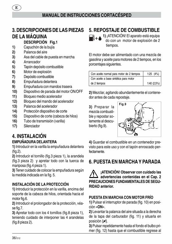
36/012
3. DESCRIPCIONES DE LAS PIEZASDE LA MÁQUINA
DESCRIPCIÓN Fig.11) Capuchón de la bujía2) Palanca del aire3) Asa del cable de puesta en marcha4) Arrancador5) Tapón depósito combustible6) Motor de explosión7) Depósito combustible8) Empuñadura delantera9) Empuñadura con mandos trasera10) Dispositivo de parada del motor ON/OFF11) Bloqueo medio acelerador12) Bloqueo del mando del acelerador13) Palanca del acelerador14) Protección dispositivo de corte15) Dispositivo de corte (cabeza de hilos)16) Tubo de transmisión (varilla)17) Silenciador
4. INSTALACIÓNEMPUÑADURA DELANTERA1) Introducir en la varilla la empuñadura delantera(fig.2).2) Introducir el tornillo (fig.3 pieza 1), la arandela(fig.3 pieza 2) y apretar todo con la tuerca demariposa (fig.4 pieza 1).3) Tener cuidado de colocar la empuñadura segúnla medida indicada en la fig. 5.
INSTALACIÓN DE LA PROTECCIÓN1) Introducir la protección en la varilla, encima delsoporte de la cabeza de hilos, orientada hacia elmotor fig.6.2) Introducir el prolongador de la protección, véa-se fig.7.3) Apretar todo con los 4 tornillos (fig.8 pieza 1),teniendo cuidado de interponer las 4 arandelas(fig.8 pieza 2).
E
MANUAL DE INSTRUCCIONES CORTACÉSPED
5. REPOSTAJE DE COMBUSTIBLE 1) ¡ATENCIÓN! El aparato está equipa do con un motor de explosión de 2 tiempos.
El motor debe ser alimentado con una mezcla degasolina y aceite para motores de 2 tiempos, en losporcentajes siguientes.
Con aceite normal para motor de 2 tiempos 1:25 (4%) Con aceite a base sintética para motor de 2 tiempos 1:40 (2,5%)
2) Mezclar, agitando abundantemente el contene-dor antes de cada repostaje.
3) Preparar lamezcla combusti-ble y repostar so-lamente al descu-bierto (fig.9).
4) Guardar el combustible en un contenedor pre-visto para este uso y con el tapón enroscado per-fectamente.
6. PUESTA EN MARCHA Y PARADA
¡ATENCIÓN! Observar con cuidado lasadvertencias contenidas en el Cap. 2
PRECAUCIONES FUNDAMENTALES DE SEGU-RIDAD anterior.
PUESTA EN MARCHA CON MOTOR FRÍO1) Pulsar el interruptor de parada (fig. 10) en posi-ción «ON».2) Levantar la palanca del aire situada a la derechade la tapa del carburador (fig. 11) y situarla enposición .3) Pulsar repetidamente hasta el fondo el bulbo pri-mer (fig. 12) hasta que el combustible regrese al
Fig.9
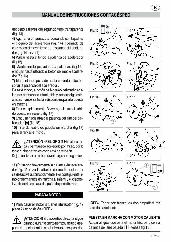
37/012
E
MANUAL DE INSTRUCCIONES CORTACÉSPED
Fig.11
Fig.12 Fig.13
Fig.14 Fig.15
Fig.16
Fig.17
Fig.18 Fig.19
�
�
�
�
�
�
� �
�
1
2
1
Fig.10
�
ON
OFF
ON
OFF
«OFF». Tener con fuerza las dos empuñadurashasta la parada total.
PUESTA EN MARCHA CON MOTOR CALIENTEActuar al igual que para el motor frío, pero con lapalanca del aire bajada (véase fig.18).
depósito a través del segundo tubo transparente(fig. 13).4) Agarrar la empuñadura, pulsando con la palmael bloqueo del acelerador (fig. 14), liberando deeste modo el movimiento de la palanca del acelera-dor (fig.14 pieza 1).5) Pulsar hasta el fondo la palanca del acelerador(fig.15).6) Manteniendo pulsadas las palancas (fig.15),empujar hasta el fondo el botón del medio acelera-dor (fig.16).7) Manteniendo pulsado hasta el fondo el botón,soltar la palanca del acelerador .De este modo, el botón de bloqueo del medio ace-lerador permanece introducido y, por consiguiente,ambas manos se hallan disponibles para la puestaen marcha.8) Tirar completamente, 3 veces, del asa del cablede puesta en marcha (fig.17).9) Empujar hacia abajo la palanca del aire del car-burador (fig.18).10) Tirar del cable de puesta en marcha (fig.17)para arrancar el motor.
¡¡ ATENCIÓN - PELIGRO !! El motor arranca y permanece acelerado por mitad, por lo
tanto el dispositivo de corte está en rotación.Dejar funcionar el motor durante algunos segundos.
11) Pulsando brevemente la palanca del acelera-dor (fig. 19 pieza 1), el botón del medio aceleradorse desactiva automáticamente. Por consiguiente, elmotor permanece en marcha al ralentí y el disposi-tivo de corte se para después de poco tiempo
PARADA MOTOR
1) Para parar el motor, situar el interruptor (fig. 19pieza 2) en posición «OFF».
¡ATENCIÓN! el dispositivo de corte siguegirando durante cierto tiempo, incluso des-
pués del accionamiento del interruptor en posición
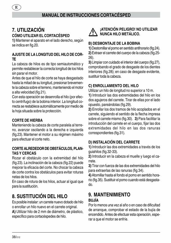
38/012
7. UTILIZACIÓNCÓMO UTILIZAR EL CORTACÉSPED1) Mantener el aparato en el lado derecho, segúnse indica en fig.20.
AJUSTE DE LA LONGITUD DEL HILO DE COR-TELa cabeza de hilos es de tipo semiautomático ypermite restablecer la correcta longitud de los hilossin parar el motor.Antes de que el hilo de corte se haya desgastadohasta la mitad de su longitud, presionar brevemen-te la cabeza sobre el terreno, manteniendo el motora alta velocidad (fig.21).Con esta operación se desenrolla el hilo (por efec-to centrífugo) de la bobina interior. La longitud co-rrecta se restablece automáticamente por medio dela hoja situada sobre la protección.
CORTE DE HIERBAManteniendo la cabeza de corte paralela al terre-no, avanzar oscilando a la derecha e izquierda(fig.23). Mantener el motor a su régimen máximopara efectuar el corte neto.
CORTE ALREDEDOR DE OBSTÁCULOS, PLAN-TAS Y CERCASRozar el obstáculo con la extremidad del hilo(fig.23). La inclinación de la cabeza (fig.22) puedemejorar la eficacia del corte. No chocar la cabezade corte contra los obstáculos para evitar roturasnetas de los hilos.En caso de rotura de los hilos, actuar al igual quepara la sustitución.
8. SUSTITUCIÓN DEL HILOEs posible instalar: un carrete nuevo dotado de hiloo enrollar un hilo nuevo en el carrete original.A) Utilizar hilo de 2 mm de diámetro, de plástico,específico para cortacéspedes de hilo.
¡ATENCIÓN PELIGRO! NO UTILIZARNUNCA HILO METÁLICO.
B) DESMONTAJE DE LA BOBINA1) Destornillar el pomo en sentido antihorario (fig.24).2) Extraer el carrete del cuerpo de la cabeza (fig.25-26).3) Limpiar con cuidado el interior del cuerpo (fig.27),comprobando el grado de desgaste de los dientesinteriores (fig.28); en caso de desgaste evidente,sustituir toda la cabeza.
C) ENROLLAMIENTO DEL HILOUtilizar un hilo de longitud no superior a 10 m.1) Introducir las dos extremidades del hilo en losdos agujeros del carrete. Tirar de ellas por el ladoopuesto, pareándolas (fig.29).2) Enrollar los dos tramos de hilo acoplados en elcarrete, siguiendo el sentido de la flecha impresasobre el carrete mismo (fig.30). 3) Para facilitar laintroducción del carrete en el cuerpo, fijar las dosextremidades del hilo en las dos ranurascorrespondientes (fig.31).
D) INSTALACIÓN DEL CARRETE1) Introducir las dos extremidades a través de losguiahilos (fig.32-33).2) Introducir en la cabeza el muelle y luego el ca-rrete.3) Tirar con fuerza de las dos extremidades del hilopara extraerlas de las ranuras (fig.34).4) Atornillar hasta el fondo el pomo en sentido hora-rio (fig.35). Sustituir el pomo cuando está desgasta-do.
9. MANTENIMIENTOBUJÍAPor lo menos una vez al año o en caso de dificultadde arranque, comprobar el estado de la bujía deencendido. Antes de efectuar esta operación, espe-rar a que el motor se enfríe.
E
MANUAL DE INSTRUCCIONES CORTACÉSPED
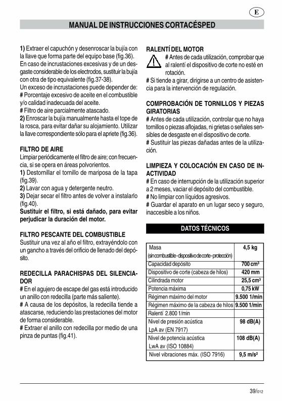
39/012
1) Extraer el capuchón y desenroscar la bujía conla llave que forma parte del equipo base (fig.36).En caso de incrustaciones excesivas y de un des-gaste considerable de los electrodos, sustituir la bujíacon otra de tipo equivalente (fig.37-38).Un exceso de incrustaciones puede depender de:# Porcentaje excesivo de aceite en el combustibley/o calidad inadecuada del aceite.# Filtro de aire parcialmente atascado.2) Enroscar la bujía manualmente hasta el tope dela rosca, para evitar dañar su alojamiento. Utilizarla llave correspondiente sólo para el apriete (fig.36).
FILTRO DE AIRELimpiar periódicamente el filtro de aire; con frecuen-cia, si se opera en áreas polvorientos.1) Destornillar el tornillo de mariposa de la tapa(fig.39).2) Lavar con agua y detergente neutro.3) Dejar secar el filtro antes de volver a instalarlo(fig.40).Sustituir el filtro, si está dañado, para evitarperjudicar la duración del motor.
FILTRO PESCANTE DEL COMBUSTIBLESustituir una vez al año el filtro, extrayéndolo conun gancho a través del orificio de llenado del depó-sito.
REDECILLA PARACHISPAS DEL SILENCIA-DOR# En el agujero de escape del gas está introducidoun anillo con redecilla (parte más saliente).# A causa de los depósitos, la redecilla tiende aatascarse, reduciendo las prestaciones del motorde forma considerable.# Extraer el anillo con redecilla por medio de unapinza de puntas (fig.41).
RALENTÍ DEL MOTOR# Antes de cada utilización, comprobar queal ralentí el dispositivo de corte no esté enrotación.
# Si tiende a girar, dirigirse a un centro de asisten-cia para la intervención de regulación.
COMPROBACIÓN DE TORNILLOS Y PIEZASGIRATORIAS# Antes de cada utilización, controlar que no hayatornillos o piezas aflojadas, ni grietas o señales sen-sibles de desgaste en el dispositivo de corte.# Sustituir las piezas dañadas antes de la utiliza-ción.
LIMPIEZA Y COLOCACIÓN EN CASO DE IN-ACTIVIDAD# En caso de interrupción de la utilización superiora 2 meses, vaciar el depósito del combustible.# No limpiar con líquidos agresivos.# Guardar el aparato en un lugar seco y seguro,inaccesible a los niños.
DATOS TÉCNICOS
Masa 4,5 kg (sin combustible - dispositivo de corte - protección) Capacidad depósito 700 cm³ Dispositivo de corte (cabeza de hilos) 420 mm Cilindrada motor 25,5 cm³ Potencia máxima 0,75 kW Régimen máximo del motor 9.500 1/min Régimen máximo de la cabeza de hilos 9.500 1/min Ralentí 2.800 1/min Nivel de presión acústica 98 dB(A) LpA av (EN 7917) Nivel de potencia acústica 108 dB(A) LwA av (ISO 10884) Nivel vibraciones máx. (ISO 7916) 9,5 m/s²
E
MANUAL DE INSTRUCCIONES CORTACÉSPED

40/012
A2.1 - Conserve este manual paraconsultas futuras.A3 – Não permita o uso do APARA-DOR DE RELVA às crianças e a pes-soas que não conheçam completamenteestas instruções.
PERIGO:A4 – Tenha cuidado com o materialarremessado pelo dispositivo de corte.A5 – Não ponha em funcionamento nemutilize o aparador de relva nas proxi-midades de pessoas, animais ou coi-sas.Durante o funcionamento recomenda-se uma distância mínima de 15 m entrea máquina e outras pessoas.A6 – O operador é responsável emcaso de acidentes ou perigos causa-dos a outras pessoas ou às coisas de-las.
EMPREGO:B1 – Utilize o APARADOR DE RELVAapenas para cortar relva e ervas ru-ins.Não utilize o aparelho para finalidadesdiferentes.B2 – Vista roupa e equipamento desegurança adequado para o empregodo APARADOR DE RELVA.Durante o emprego vista roupa justaao corpo e não solta.B3 – Utilize óculos de protecção ou vi-seira homologados.B3.1 – Utilize protectores auriculareshomologados contra o ruído.B3.2 – Utilize o capacete de protecçãoem caso de risco de queda de objec-tos.B4 – Calce sapatos robustos com so-las anti-derrapantes.B5 – Utilize luvas grossas.B6 – Quem utilizar o APARADOR DE
P
MANUAL DE INSTRUÇÕNES APARADOR DE RELVA
1. PARABÉNSPrezado Cliente, parabéns por ter escolhido umnosso produto para o jardim.
O APARADOR DE RELVA GTL 26 foi construídono respeito das normas de segurança em vigor emdefesa do consumidor.
Neste manual são descritas e ilustradas as váriasoperações de montagem, de uso e as operaçõesde manutenção necessárias para manter em perfeitaeficiência o Seu APARADOR DE RELVA GTL 26.
PARA FACILITAR A LEITURAAs ilustrações correspondentes àmontagem da máquina encontram-
se na orelha da capa, no início deste manual.Mantenha abertas estas páginas durante a leituradas instruções de montagem e de utilização.
Caso o Seu APARADOR DE RELVA necessite deassistência ou reparação, rogamos que se dirija aonosso revendedor, ou a um centro de assistênciaautorizado.
2. PRECAUÇÕES FUNDAMENTAISDE SEGURANÇA
NORMAS GERAIS
ADVERTÊNCIASA1 – O emprego do APARADOR DERELVA exige o respeito das normasde segurança.A2 – Quem quer utilize o APARADORDE RELVA deve primeiro ler com aten-ção o manual de instruções e manu-tenção e familiarizar-se completamentecom os comandos para um uso cor-recto do aparelho.
41/012
RELVA deve estar em boas condições.NÃO UTILIZE O APARADOR DERELVA em condições de cansaço, demal estar ou sob o efeito do álcool e deoutras drogas.B7 - ATENÇÃO! Os gases de descar-ga são venenosos e asfixiantes. Se ins-pirados, portanto, até podem ser mor-tais. Não ponha em funcionamento omotor num local fechado ou com venti-lação escassa.B8 – O emprego prolongado do apa-relho pode causar problemas de cir-culação sanguínea nas mãos (doença“dos dedos brancos”) atribuível às vi-brações.Factores que influem na manifestaçãodos distúrbios podem ser:- Predisposição pessoal do operadora uma escassa irroração sanguíneadas mãos.- Utilização do aparelho a baixas tem-peraturas (aconselham-se portanto lu-vas quentes).- Longos tempos de uso sem interrup-ção (aconselha-se uma utilização comintervalos).- Ao se manifestarem formigueiro e en-torpecimento, recomenda-se a consul-tar um médico.B8.1 – Sustentar o aparelho semprecom ambas as mãos.Assumir uma posição estável e seguranas pernas.B8.2 - O Aparador de relva é projecta-do para ser utilizado no lado direito dooperador (veja a fig. 20).Segure a pega posterior (com coman-dos) com a mão direita e a pega ante-rior com a mão esquerda.B9 - ATENÇÃO! a gasolina e os seusvapores são extremamente inflamáveis.
PERIGO DE QUEIMADURAS E IN-CÊNDIOB9.1 – Pare o motor antes do abaste-cimento.B9.2 – Não fume enquanto estiver aabastecer de carburante.B9.3 – Seque o carburante eventual-mente derramado. Ponha em funcio-namento o motor longe do lugar deabastecimento.B9.4 – Assegure-se de que o bujão doreservatório está bem apertado.Preste atenção com eventuais perdas.B10 – Com o aparelho é fornecida umaPROTECÇÃO DO DISPOSITIVO DECORTE (Fig.1 det.14-15) que deveser montada antes do emprego (vejaas instruções de montagem).Não ponha em funcionamento nem uti-lize o aparelho se este estiver despro-vido da protecção.B10.1 - PERIGO! Feridas devidas aocontacto com o dispositivo de corte;arremesso de material contra o opera-dor.Não modifique a protecção.Substitua a protecção se danificada,apenas com peças de origem.B10.2 - PERIGO! Não monte fiometálico na cabeça de corte.B10.3 - O BLOQUEIO DO COMAN-DO DO ACELERADOR (veja fig.1det.12): impede o accionamento aci-dental da alavanca do acelerador.B10.4 - INTERRUPTOR (ON/OFF)de paragem do motor (fig.1 det.10).PERIGO! Atenção, o dispositivo decorte continua a girar por um certo tem-po também depois de colocado o inter-ruptor na posição “OFF”. Segure fir-memente as duas pegas até à para-gem completa. Veja o capítulo ARRAN-QUE E PARAGEM.
P
MANUAL DE INSTRUÇÕNES APARADOR DE RELVA
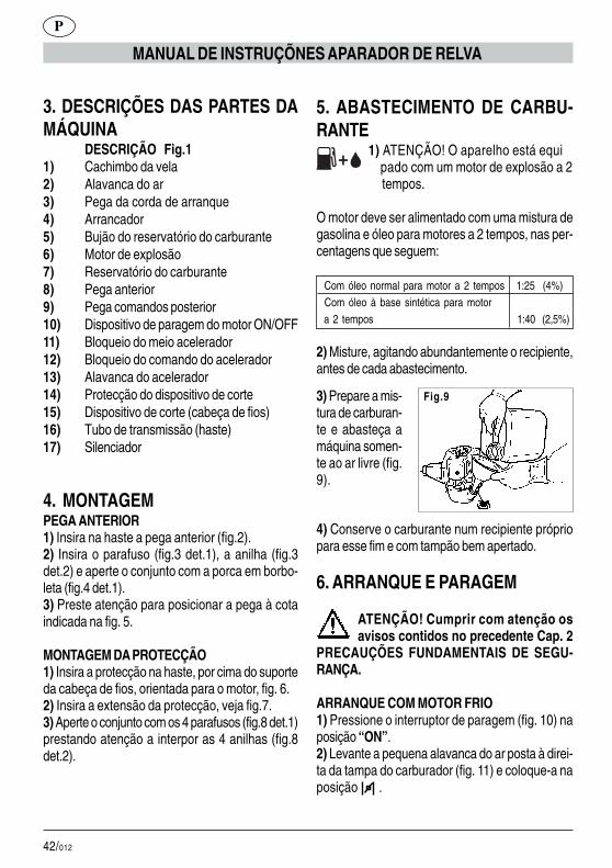
42/012
P
MANUAL DE INSTRUÇÕNES APARADOR DE RELVA
3. DESCRIÇÕES DAS PARTES DAMÁQUINA
DESCRIÇÃO Fig.11) Cachimbo da vela2) Alavanca do ar3) Pega da corda de arranque4) Arrancador5) Bujão do reservatório do carburante6) Motor de explosão7) Reservatório do carburante8) Pega anterior9) Pega comandos posterior10) Dispositivo de paragem do motor ON/OFF11) Bloqueio do meio acelerador12) Bloqueio do comando do acelerador13) Alavanca do acelerador14) Protecção do dispositivo de corte15) Dispositivo de corte (cabeça de fios)16) Tubo de transmissão (haste)17) Silenciador
4. MONTAGEMPEGA ANTERIOR1) Insira na haste a pega anterior (fig.2).2) Insira o parafuso (fig.3 det.1), a anilha (fig.3det.2) e aperte o conjunto com a porca em borbo-leta (fig.4 det.1).3) Preste atenção para posicionar a pega à cotaindicada na fig. 5.
MONTAGEM DA PROTECÇÃO1) Insira a protecção na haste, por cima do suporteda cabeça de fios, orientada para o motor, fig. 6.2) Insira a extensão da protecção, veja fig.7.3) Aperte o conjunto com os 4 parafusos (fig.8 det.1)prestando atenção a interpor as 4 anilhas (fig.8det.2).
5. ABASTECIMENTO DE CARBU-RANTE
1) ATENÇÃO! O aparelho está equi pado com um motor de explosão a 2
tempos.
O motor deve ser alimentado com uma mistura degasolina e óleo para motores a 2 tempos, nas per-centagens que seguem:
Com óleo normal para motor a 2 tempos 1:25 (4%) Com óleo à base sintética para motor a 2 tempos 1:40 (2,5%)
2) Misture, agitando abundantemente o recipiente,antes de cada abastecimento.
3) Prepare a mis-tura de carburan-te e abasteça amáquina somen-te ao ar livre (fig.9).
Fig.9
4) Conserve o carburante num recipiente própriopara esse fim e com tampão bem apertado.
6. ARRANQUE E PARAGEM
ATENÇÃO! Cumprir com atenção osavisos contidos no precedente Cap. 2
PRECAUÇÕES FUNDAMENTAIS DE SEGU-RANÇA.
ARRANQUE COM MOTOR FRIO1) Pressione o interruptor de paragem (fig. 10) naposição “ON”.2) Levante a pequena alavanca do ar posta à direi-ta da tampa do carburador (fig. 11) e coloque-a naposição .
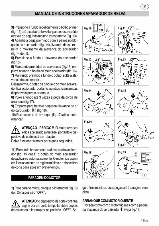
43/012
P
MANUAL DE INSTRUÇÕNES APARADOR DE RELVA
3) Pressione a fundo repetidamente o bolbo primer(fig. 12) até o carburante voltar para o reservatórioatravés do segundo tubinho transparente (fig. 13).4) Apanhe a pega premindo com a palma no blo-queio do acelerador (fig. 14), livrando dessa ma-neira o movimento da alavanca do acelerador(fig.14 det.1).5) Pressione a fundo a alavanca do acelerador(fig.15).6) Mantendo premidas as alavancas (fig.15) em-purre a fundo o botão do meio acelerador (fig.16).7) Mantendo premido a fundo o botão, solte a ala-vanca do acelerador .Dessa forma, o botão de bloqueio do meio acelera-dor fica accionado, portanto as mãos ficam ambasdisponíveis para o arranque.8) Puxe a fundo até 3 vezes a pega da corda dearranque (fig.17).9) Empurre para baixo a pequena alavanca do ardo carburador (fig.18).10) Puxe a corda de arranque (fig.17) até o motorarrancar.
ATENÇÃO - PERIGO !! O motor arrancae fica acelerado a metade, portanto o dis-
positivo de corte está em rotação.Deixe funcionar o motor por alguns segundos.
11) Premindo brevemente a alavanca do acelera-dor (fig. 19 det.1) o botão do meio aceleradordesactiva-se automaticamente. O motor fica assimem funcionamento ao regime mínimo e o dispositivode corte pára após um breve tempo.
PARAGEM DO MOTOR
1) Para parar o motor, coloque o interruptor (fig. 19det. 2) na posição “OFF”.
ATENÇÃO! o dispositivo de corte continuaa girar por um certo tempo também depois
de colocado o interruptor na posição “OFF”. Se-
Fig.11
Fig.12 Fig.13
Fig.14 Fig.15
Fig.16
Fig.17
Fig.18 Fig.19
�
�
�
�
�
�
� �
�
1
2
1
Fig.10
�
ON
OFF
ON
OFF
gure firmemente as duas pegas até à paragem com-pleta.
ARRANQUE COM MOTOR QUENTEProceda como com o motor frio mas com a peque-na alavanca do ar baixada (veja fig.18).
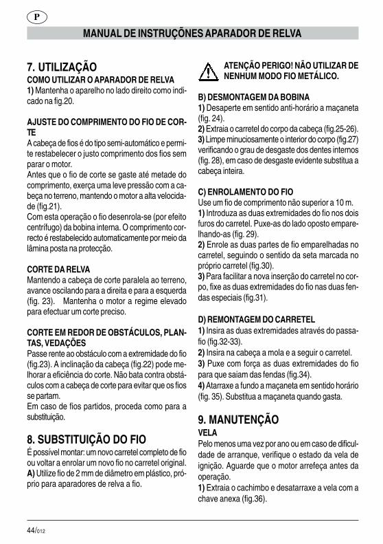
44/012
P
MANUAL DE INSTRUÇÕNES APARADOR DE RELVA
7. UTILIZAÇÃOCOMO UTILIZAR O APARADOR DE RELVA1) Mantenha o aparelho no lado direito como indi-cado na fig.20.
AJUSTE DO COMPRIMENTO DO FIO DE COR-TEA cabeça de fios é do tipo semi-automático e permi-te restabelecer o justo comprimento dos fios semparar o motor.Antes que o fio de corte se gaste até metade docomprimento, exerça uma leve pressão com a ca-beça no terreno, mantendo o motor a alta velocida-de (fig.21).Com esta operação o fio desenrola-se (por efeitocentrífugo) da bobina interna. O comprimento cor-recto é restabelecido automaticamente por meio dalâmina posta na protecção.
CORTE DA RELVAMantendo a cabeça de corte paralela ao terreno,avance oscilando para a direita e para a esquerda(fig. 23). Mantenha o motor a regime elevadopara efectuar um corte preciso.
CORTE EM REDOR DE OBSTÁCULOS, PLAN-TAS, VEDAÇÕESPasse rente ao obstáculo com a extremidade do fio(fig.23). A inclinação da cabeça (fig.22) pode me-lhorar a eficiência do corte. Não bata contra obstá-culos com a cabeça de corte para evitar que os fiosse partam.Em caso de fios partidos, proceda como para asubstituição.
8. SUBSTITUIÇÃO DO FIOÉ possível montar: um novo carretel completo de fioou voltar a enrolar um novo fio no carretel original.A) Utilize fio de 2 mm de diâmetro em plástico, pró-prio para aparadores de relva a fio.
ATENÇÃO PERIGO! NÃO UTILIZAR DENENHUM MODO FIO METÁLICO.
B) DESMONTAGEM DA BOBINA1) Desaperte em sentido anti-horário a maçaneta(fig. 24).2) Extraia o carretel do corpo da cabeça (fig.25-26).3) Limpe minuciosamente o interior do corpo (fig.27)verificando o grau de desgaste dos dentes internos(fig. 28), em caso de desgaste evidente substitua acabeça inteira.
C) ENROLAMENTO DO FIOUse um fio de comprimento não superior a 10 m.1) Introduza as duas extremidades do fio nos doisfuros do carretel. Puxe-as do lado oposto empare-lhando-as (fig. 29).2) Enrole as duas partes de fio emparelhadas nocarretel, seguindo o sentido da seta marcada nopróprio carretel (fig.30).3) Para facilitar a nova inserção do carretel no cor-po, fixe as duas extremidades do fio nas duas fen-das especiais (fig.31).
D) REMONTAGEM DO CARRETEL1) Insira as duas extremidades através do passa-fio (fig.32-33).2) Insira na cabeça a mola e a seguir o carretel.3) Puxe com força as duas extremidades do fiopara que saiam das fendas (fig.34).4) Atarraxe a fundo a maçaneta em sentido horário(fig. 35). Substitua a maçaneta quando gasta.
9. MANUTENÇÃOVELAPelo menos uma vez por ano ou em caso de dificul-dade de arranque, verifique o estado da vela deignição. Aguarde que o motor arrefeça antes daoperação.1) Extraia o cachimbo e desatarraxe a vela com achave anexa (fig.36).

45/012
P
MANUAL DE INSTRUÇÕNES APARADOR DE RELVA
Em caso de incrustações excessivas e notável des-gaste dos eléctrodos, substitua a vela por uma detipo equivalente (fig.37-38).Um excesso de incrustações pode ser devido a:# Percentagem excessiva de óleo no carburante e/ou qualidade não adequada do óleo.# Filtro do ar parcialmente entupido.2) Atarraxe a vela à mão até o fundo da rosca paraevitar danos na sua sede. Utilize a chave especialapenas para apertar (fig.36).
FILTRO DO ARLimpe periodicamente o filtro do ar; frequentementese trabalhar em áreas poeirentas.1) Desaperte o parafuso em borboleta da tampa(fig. 39).2) Lave com água e detergente neutro.3) Faça secar o filtro antes de voltar a colocá-lo(fig.40).Substitua o filtro se danificado para não com-prometer a duração do motor.
FILTRO DO TUBO DO CARBURANTESubstitua uma vez por ano o filtro extraindo-o comum gancho pela abertura de abastecimento do re-servatório.
REDE PÁRA-FAÍSCAS DO SILENCIADOR# No orifício de descarga do gás está inserido umanel com rede (parte mais saliente).# Devido aos depósitos, a rede tende a entupir-sereduzindo notavelmente os rendimentos do motor.# Extraia o anel com rede por meio de um alicate depontas longas (fig.41).
REGIME MÍNIMO DO MOTOR# Verifique a cada emprego que ao regime mínimoo dispositivo de corte não esteja em rotação.# Se tende a rodar, contacte um centro de assistên-cia para a intervenção de regulação.
VERIFICAÇÃO DE PARAFUSOS E PARTESROTATIVAS# Antes de cada emprego controle que não hajaparafusos ou partes desapertadas e que não hajarachas ou fortes desgastes no dispositivo de corte.# Substitua as partes danificadas antes do empre-go.
LIMPEZA E ARMAZENAGEM# Em caso de interrupção de utilização superior a 2meses, esvazie o reservatório do carburante.# Não limpe com líquidos agressivos.# Conserve o aparelho em local seco e seguro,não acessível às crianças.
DADOS TÉCNICOS
Peso 4,5 Kg (sem carburante – dispositivo de corte – protecção) Capacidade do reservatório 700 cm³ Dispositivo de corte (cabeça de fios) 420 mm Cilindrada motor 25,5 cm³ Potência máxima 0,75 KW Regime máximo do motor 9.500 1/min Regime máximo da cabeça de fios 9.500 1/min Regime de mínimo 2.800 1/min Nível de pressão acústica 98 dB(A) LpA av (EN 7917) Nível de potência acústica 108 dB(A) LwA av (ISO 10884) Nível máx. de vibrações (ISO 7916) 9,5 m/s²

46/012
1 - GRATULACJE&�������7���������4��� � ������6�� ����4������ �� ���������4�������4��� �������������������5���6 ������4������ �� �������� 6��������8��� ���9������������ ����������-��������������� ��������������������:������������������������� ����9��������4;���� � :���� ������ � ���������� �� ������2��� �����������������������6�������� �������������:����������������������������������
������������������$� ����������������������4;����� :����
������ ������������� ������������2���4��������5���������������� ���������4��������� %������ ��5����� � ��������������� ���� ����� ������ � � ����������
<���������� 6������ ���4�5�����4��� � � 6� ������� ������� ����������������������������� 6��������� ������������ �������65 4���������
2. PODSTAWOWE NORMYBEZPIECZEÑSTWA
NORMY PODSTAWOWE
UWAGI:A1 –� ����� �������� KOSIARKI � ���4���� �����������4����� ����6��������8���A2 – 7������ ���� � ������������������� �����
����������� ���� ���� ���������� �� ������2��������������9�� � ���������� ��� ���5������ ������������� � ��� �����5�����65 4����������A2.1 - =������ �������������9����� ���� ����� ������ �����9� �����5��9��� �������A3 – =��� ���� �������� �������KOSIARKI p����������� � 6���6�����;������������������ �� �������������� �������
��� ��������������A4 – >����� ��� �������5���� ����� ������ ���������������A5 –�=���5������������ ������������ � ��6��� � �;6���������� 6����������;�W momencie koszenia nale����������� ��� � ����45�2�������?@����������9��;6�A6 – %�������������������������������� ������������� 6���������������6����������9�� ������4��������������6��
� ���������B1 –� &�������������������������������������9��;�Nie stoso��� ���������� �������9����;�B2 – ������� �������7%&+'$7A� ������� ��������������� 6���������;���� �6����������������������6��� B���B3 –� =���� �� ������6������������� � 6����������� 9�����4������5�����������
PL
INSTRUCJE KOSIARKA

47/012
INSTRUCJE KOSIARKA
PL
B3.1 – =���� 9�����4������6��������������� ��������9�5����B3.2 –� =���� ����� ��;����6��������� ��� ��������� ������� ���� �����������5 �B4 – =�����������6 �����6�������������������2���4���B5 –�=�������������������B6 – 7������ ���� ��������������6������6���:��� ie. ���� � ��!���������6�������������������� �5��� ������� �� � � 6���� �5���� ����9�� � � 6��������;�B7 - UWAGA! <��������������� �� � ��� ����9���� ����� ����� �� � ������ <��� ������9���� ����� 6��� ���2�����������=���5�������������� �������������9����������9� �� 5�6�����������9�B8 –� C6��� �5 4��� �������������� �� �������� �� ����6��������4�� ����������6������ ������� � ���� �����9� )�9���6�� 6��5��9����;,�������������� ��;����5������� �������� ���6���;���������9����4��6��3-� ������������� ��6����������������5�6�4��������������-�>���������� �������������������9� �������� ���9)��������� �������� 4� 6��9������,�-�C6����5 4������ ���������)��������� ��6������ ������
�����,�-� -� �������� �� 4��� ������������ � 6������������������� ��������������������B8.1 –� D�������� ��������������������������� ����������� �� 6����5���������B8.2 –� 7������� ����5������������������ ���� ��������������������������)�����:�4 �����",�D������� ������ �9��� )������������� ,� ����� ����� � �9��������������������B9 - UWAGA! E���������������5������������ ������������������������� ���B9.1 – C������������������������������6�������B9.2 –� =��� ������ � ����������������B9.3 – Wysus���� �������6�������B9.4 – &�������������6����������5����5����������������Uwaga na wycieki.B10 – C� ��������������������� ���C ' E F C � + F / C F = + F>$CAGCF=+'�D=A/F<%�)H�4�?����4;5�?IJ?@,����;������������������� ����� �����������)���������� ���������� ,�=���5������ ���� ���� ���� ���������� 6����6������������ "#�"� $��� �������������%�$������������ ���������� � ����������� ������K

48/012
���������� �������5 � ���� �� ��������������=��� ��������� ������ ��6������������9�-�������� ����������6������������ ������ �����4����������2��� "#���$���� �������������%�&'�()*+),-.�/&*0&�1+-/),'2*-�34),&56�+*75'2�B10.3 – EL%7'G'& D F $ % - ' = + '�$C1&�+F&C'=+'�)������:�4�?����4;5�?�,3� E��� �������������5���������B�4���������������B10.4 - -1.A/C=+7�)%=�%HH,������������ ������� ):�4�?����4;5�?",���� �������������%>�4������2���������������������� ����2� ���� ����� �� ������ � �5�������� ���������� � “OFF”�� D������������ ��� �9���� ��� ����5�����4���������������������������5� -.A/CF=+F� +C'D$ZYMANIE.
3. OPIS CZÊŒCI MASZYNYOPIS Fig.1
"8 ��������2�����8 ��5���B�4������������3) Uchwyt liny rozruchu4) Rozrusznik98 7������6�����������6������6) Silnik iskrowy:8 C6����������6������8) Uchwyt przedni9) Uchwyt tylny"#8 >����������������������� �9
�������%=�%HH�
11) E���������5���������������12) Blokada przyspieszania13) GB�4���� ������������14) C�6������������ ���������������4�15) >��������������������)45����
��5��,"�8 ������������":8 D5 ���
4. MONTA UCHWYT PRZEDNI1) C�5����������������������� �9���):�4��,�2)�-5����� 2� 6��� ):�4� � ����4;5� ?,�����5�����):�4� �����4;5��,������������������� ����������):�4�I�����4;5�?,�3)� >������ �6�� ����� �9��� ���������������������:�4��@�
���� �� ����������1) C�5�������6�����������������������������������45�������5������������������ �� ��������:�4�!�2) C�5������������������6������������������:�4�#�3) G��������������������� �I�2� 6���):�4�M�����4;5�?,�����������������5����� I�����5�����):�4�M�����4;5��,�
5. NALEWANIE BENZYNY 1) >-'<'N�>��������������������������������� ����
&������ � �� 6��� �������� ��������6����������������������������������;� ���9�� � ����� �����9����������93
Olejem normalny do silników dwusuwowych� �%�������������������������
� � ��� �����;� � ���9
1:25 (4%)
�?3I"��)��@O,
PL
INSTRUCJE KOSIARKA
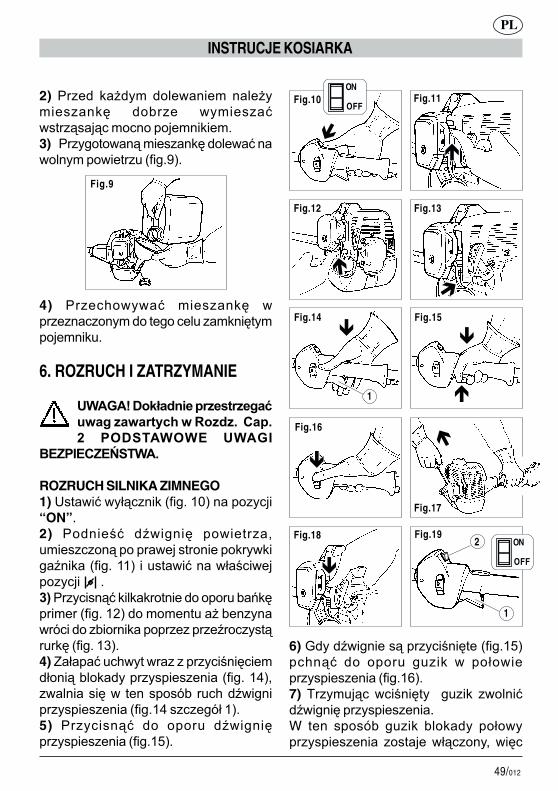
49/012
2) ������ ������� ���������� ��������������� ��6���� ����������������������������������3)�������4�������������������������������������� �):�4�P,�
4) �����9����� ��������� �������������������4����� ������������������� �
6. ROZRUCH I ZATRZYMANIE
���%��)04-;*&'�<=>'1+=>'3-.?,-3�>-,-=+65@�,��)>;>����-<��� ���������� ����
�������������
ROZRUCH SILNIKA ZIMNEGO1)�>������5�������):�4��?",�����������“ON”.2)� ������2�� �B�4���� ��������� ���������������������������������4�B�����):�4��??,��� ��������5�2�����������������A8������������������������������� �6�8���������):�4��?�,���������� ����6�������;�������6��������������������B�������� ����):�4��? ,�4)�C�5����� �9���������������2��������5�����6��������������������):�4��?I,������������ ������;6�� �9��B�4���������������):�4�?I�����4;5�?,�5)� ���������� ��� ���� � �B�4����������������):�4�?@,�
Fig.9
INSTRUCJE KOSIARKA
PL
6)�<����B�4������������2������):�4�?@,��9���� ��� ���� � 4 ���� � ��5����������������):�4�?!,�7) D���� ������2������ 4 ���� �������B�4�����������������W ten sposó6� 4 ���� 6������� ��5��������������� �������5�����������
Fig.11
Fig.12 Fig.13
Fig.14 Fig.15
Fig.16
Fig.17
Fig.18 Fig.19
�
�
�
�
�
�
� �
�
1
2
1
Fig.10
�
ON
OFF
ON
OFF

50/012
7. U¯YTKOWANIE��� ��!��������1)��������������������������):�4� !�����?,��������2�������):�4� !�����4;5��,�2) ��������������������������������������������������:�4� #J M�
���������������� ������������<5����� ��5��� ������� ��4 ������������������ � ������� ��� ��� ��5��� ��5��������� ��5 ���� ��5��� ������������4������� �� ������������� �� ��):�4� P,�<��� ����4������ ��5��� �6��� � ��� ��������������6����������������6��� ��6����������� � �5����� �� � ���� ��;6���4 ������
CIECIE TRAWY>����� �����;����4������������45����������� ��������� �����������������������������������):�4�I",�G���������������������������������5���9�6�����9�
�6����������6������������������� �9 �8)� �����4���� � ����� �B�4���� �������� �9 �):�4�?#,�9)� ��9���� ��� ��5 � ��5�� �B�4������������4�B����������):�4�?M,�10) �����4������������� �9 �):�4�?#,������5����������������
����B���� �������������%%&������ 5����� ��� �� ���� ���
��5����������2�������� ��������������������:������6��� ������������������������������������� ���
11)� =�� ��;���� ���������� �B�4����������������):�4��?P������?,��4 ������5���� ������������� ������ ��� ������������� &������ ���������� ������������������2������ ��������������������������������;�������9����
ZATRZYMANIE SILNIKA
1)�'6���5������������ ������5������):�4��?P�����4;5��,������������“OFF”.
UWAGA!�>�������������������6������ �6����5�� ��� ������ ����2
������������ ������ ��5������ ������������“OFF”��D������������������ �9������������5�����4��������������
������C����D������������������������������������� ������4����������������B�4�������������6�����������)������:�4�?M,�
Fig.16
Fig.17
Fig.18 Fig.19
� �
�
1
2 ON
OFF
PL
INSTRUCJE KOSIARKA

51/012
CIECIE DOOKO�� �������E�F�����F����E�L����� �������� ���������� ��8�;����5���):�4�� ,�������9�������45�����):�4���,���������������:������������=��� ������������������45��������������������������������5�����������������5���-��������� ���������������5���������������������������������������
G�������� ���������� ���������3� ���� �� ��� � 6���������5���������4���������� ���A) &��������5��������������2��������������������������������������
������� �������������%����� ��!��������TALOWEJ
8������� �������1)� %�������� ��������� � ���� �� �������������� �9 ����;�����4���):�4��I,�2)�Q���4������ �����45�����):�4��@J�!,�3)�G��5����������2��������������� ):�4��#,�� �������� ���� � �������������4�� ��6������ � ):�4��M,��-�������� ��������4��� �������������45�����
�8�������� ����R�5������������6����5 ��������?"���1)� -5����� ���� ��8�;��� ��5��� ������;� �� ���� �����4���� ��8�;��� ��5������������������):�4��P,�2) =������ ����� ��8�;��� ��� �� ����5 4�����5����6���������� ���):�4� ",�3)� '6�� 5����� ��5������� �� ��� ������ � ����������� ����� ��8�;����5�������;�9���������):�4� ?,�
�8������������� �������1) -5����� ���� ��8�;��� ��5��� ������;��� ���):�4� �J ,�2)�-5��������45����������������� ���3) �����4����������������8�;�����5�������6����5����45�6��8��):�4� I,�4)�G��������������� ��������������� �� �4����� �� � �9������;��� ��4���):�4� @,��-��������� �� ��������������������������������
9. CZYNNOŒCI KONSERWACYJNE���������������������������� 6���������� �� ���2������� �9 ��������������2�������5������������ ������� ��������� � ��� �95���������������1) Q���4�����������������������2���������������� �� �������� �� ����):�4� !,�-� �������� � ����������� ��� ��� � 6�������4�� � ������ ��������� ������2����������������������4�����4���� �):�4� #J M,�=������� ��� ��� ����� 6����������3#��6���� ������2�������� ������������ 6���5�2��������2��������� �# zatkanym ���2�����:����������������2)�$������������������2����������8��4��� � �� ����� �6�� ���� �������� ����6����� 7� ��� ���������� � ������ ����8���4��������������):�4� !,�
FILTR POWIETRZA/������2��������2����:���������������H�������2��������2��������eli kosiarka pracujew strefach zakurzonych.1)�%��������2� 6���������):�4� P,�2) ��������� 6��� �������������4������
INSTRUCJE KOSIARKA
PL

52/012
3)���������5��������:������������� ���):�4�I",��6(&'*&.�H&/+=�3;6�2'1+�?1>0);>)*6�-I6*&'�10=J5&.�K6,)+*)L5&�1&/*&0-�
���������WAKOWY BENZYNYH������������� ����� ��� ��-� ������� �����������4���� 4�� 9�����������������6��������
������ �������D��������# -� � ��������9���� ��5������ �������2���8� �� ������ )���2�� ���6��������������,�# &�����������������������4�������������������������2��������#�-����4��������2���8����������������):�4�I?,�
MINIMALNE OBROTY SILNIKA#�=����������������������������4� �����������6�� ���������� ����������6����5��������������������9��6�����9�������# W przypadku obracan��� ��� �������������45��������������� ���65 4����� ���4 ������
�������� ��� � �� ������� �������C# ������ ������� ������������������ ���� ������������� 2� 6� ���� ����������2����&����������6�����6�5���������� � 6��������4��� ������ �������� ��������# -�������� ���2��� � ����� ����� �����������
CZYSZCZENIE I KONSERWACJA# -��������� �4���������������6����� ��������������������������������������;������6���������6�������#�=������2�����4���������5������#� �����9����� ���������� ����������� � �9��� ��6���������������������������4 ��������
DANE TECHNICZNE
��/����� 4,5 kg
��)6���������S� ��������������������S���6�����������,
���������2���6����������������������������������700 cm³
��C��;5�����������)45�������5��, 420 mm
���������2�������� 25,5 cm³
Moc maksymalna 0,75 kW
Maksymalne obroty silnika 9.500 1/min
� ������������6�����45�������5����� 9.500 1/min
Minimalne obroty 2.800 1/min
�����������2��������� ������4��� 98 dB(A)
LpA av (EN 7917)
Poziom mocy akustycznej 108 dB(A)
LwA av (ISO 10884)
Maksymalny poziom wibracji 9,5 m/s²
(ISO 7916)
PL
INSTRUCJE KOSIARKA

53/012
note _________________________________________________________________________________________________________________________________________________________________________________________________________________________________________________________________________________________________________________________________________________________________________________________________________________________________________________________________________________________________________________________________________________________________________________________________________________________________________________________________________________________________________________________________________________________________________________________________________________________________________________________________________________________________________________________________________________________________________________________________________________________________________________________________________________________________________________________________________________________________________________________________________________________________________________________________________________________________________________________________________________________________________________________________________________________________________________________________________________________________________________________________________________________________________________________________________________________________________________________________________________________________________________________________________________________________________________________________________________________________________________________________________________________________________________________________________________________________________________________________________________________________________________________________________________________________________________________________________________________________________________________________________________________________________________________________________

54/012
note _________________________________________________________________________________________________________________________________________________________________________________________________________________________________________________________________________________________________________________________________________________________________________________________________________________________________________________________________________________________________________________________________________________________________________________________________________________________________________________________________________________________________________________________________________________________________________________________________________________________________________________________________________________________________________________________________________________________________________________________________________________________________________________________________________________________________________________________________________________________________________________________________________________________________________________________________________________________________________________________________________________________________________________________________________________________________________________________________________________________________________________________________________________________________________________________________________________________________________________________________________________________________________________________________________________________________________________________________________________________________________________________________________________________________________________________________________________________________________________________________________________________________________________________________________________________________________________________________________________________________________________________________________________________________________________________________________

55/012
note _________________________________________________________________________________________________________________________________________________________________________________________________________________________________________________________________________________________________________________________________________________________________________________________________________________________________________________________________________________________________________________________________________________________________________________________________________________________________________________________________________________________________________________________________________________________________________________________________________________________________________________________________________________________________________________________________________________________________________________________________________________________________________________________________________________________________________________________________________________________________________________________________________________________________________________________________________________________________________________________________________________________________________________________________________________________________________________________________________________________________________________________________________________________________________________________________________________________________________________________________________________________________________________________________________________________________________________________________________________________________________________________________________________________________________________________________________________________________________________________________________________________________________________________________________________________________________________________________________________________________________________________________________________________________________________________________________
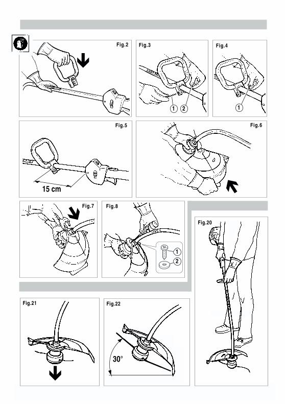
58/012
�
Fig.2 Fig.3 Fig.4
Fig.5 Fig.6
Fig.7 Fig.8
Fig.20
1 2 1
15 cm ��
1
2
30°�
Fig.21 Fig.22
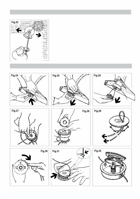
59/012
Fig.24 Fig.25 Fig.26
Fig.27 Fig.28
Fig.32
Fig.29
Fig.30 Fig.31
Fig.23� �
� � �
�
�
��
�

60/012
Fig.33 Fig.34
Fig.37 Fig.38
Fig.39 Fig.40
Fig.41
Fig.36
�
�
0,5
- 0,6
mm
�
�
Fig.35
��
�