Rif.: 23 - 08 A&D - MC Informa - Giancarlo Mariani - Agente ... - S120...Smart Line Module 16 kW...
23
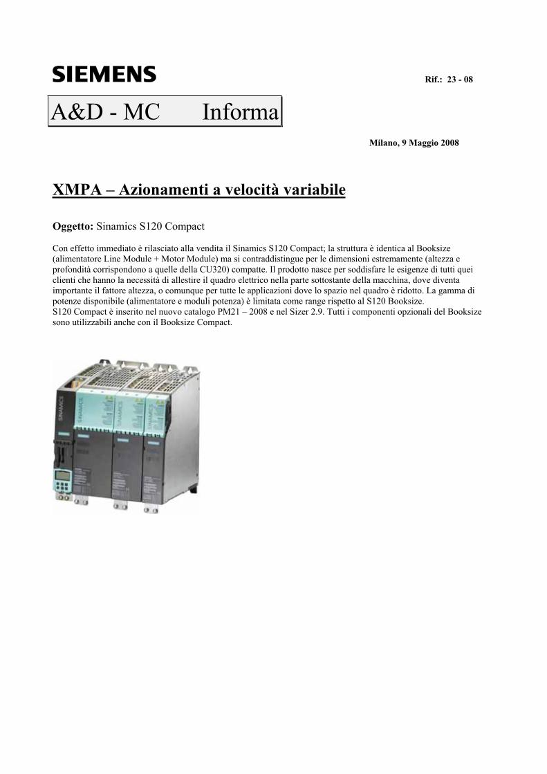
Rif.: 23 - 08 A&D - MC Informa Milano, 9 Maggio 2008 XMPA – Azionamenti a velocità variabile Oggetto: Sinamics S120 Compact Con effetto immediato è rilasciato alla vendita il Sinamics S120 Compact; la struttura è identica al Booksize (alimentatore Line Module + Motor Module) ma si contraddistingue per le dimensioni estremamente (altezza e profondità corrispondono a quelle della CU320) compatte. Il prodotto nasce per soddisfare le esigenze di tutti quei clienti che hanno la necessità di allestire il quadro elettrico nella parte sottostante della macchina, dove diventa importante il fattore altezza, o comunque per tutte le applicazioni dove lo spazio nel quadro è ridotto. La gamma di potenze disponibile (alimentatore e moduli potenza) è limitata come range rispetto al S120 Booksize. S120 Compact è inserito nel nuovo catalogo PM21 – 2008 e nel Sizer 2.9. Tutti i componenti opzionali del Booksize sono utilizzabili anche con il Booksize Compact.
Transcript of Rif.: 23 - 08 A&D - MC Informa - Giancarlo Mariani - Agente ... - S120...Smart Line Module 16 kW...
Rif.: 23 - 08
A&D - MC InformaMilano, 9 Maggio 2008
XMPA – Azionamenti a velocità variabile
Oggetto: Sinamics S120 Compact
Con effetto immediato è rilasciato alla vendita il Sinamics S120 Compact; la struttura è identica al Booksize(alimentatore Line Module + Motor Module) ma si contraddistingue per le dimensioni estremamente (altezza e profondità corrispondono a quelle della CU320) compatte. Il prodotto nasce per soddisfare le esigenze di tutti queiclienti che hanno la necessità di allestire il quadro elettrico nella parte sottostante della macchina, dove diventaimportante il fattore altezza, o comunque per tutte le applicazioni dove lo spazio nel quadro è ridotto. La gamma di potenze disponibile (alimentatore e moduli potenza) è limitata come range rispetto al S120 Booksize.S120 Compact è inserito nel nuovo catalogo PM21 – 2008 e nel Sizer 2.9. Tutti i componenti opzionali del Booksizesono utilizzabili anche con il Booksize Compact.
Negri Aldo Voice: +39 02243 62281
Product Manager Fax: +39 02243 62971
Variable Speed Drives System Mail: [email protected]
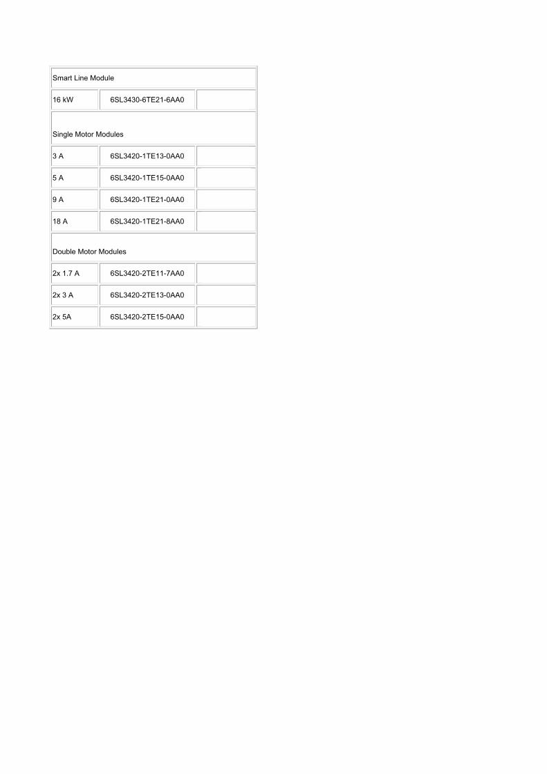
Smart Line Module
16 kW 6SL3430-6TE21-6AA0 1.133 EUR
Single Motor Modules
3 A 6SL3420-1TE13-0AA0 734,8 EUR
5 A 6SL3420-1TE15-0AA0 771,1 EUR
9 A 6SL3420-1TE21-0AA0 825 EUR
18 A 6SL3420-1TE21-8AA0 1.309 EUR
Double Motor Modules
2x 1.7 A 6SL3420-2TE11-7AA0 920,7 EUR
2x 3 A 6SL3420-2TE13-0AA0 1.100 EUR
2x 5A 6SL3420-2TE15-0AA0 1.155 EUR
Negri Aldo Voice: +39 02243 62281
Product Manager Fax: +39 02243 62971
Variable Speed Drives System Mail: [email protected]
SINAMICS S120Line Modules and line-side components
Smart Line Modules in compact booksize format
3/83Siemens PM 21 · 2008
3■ Overview
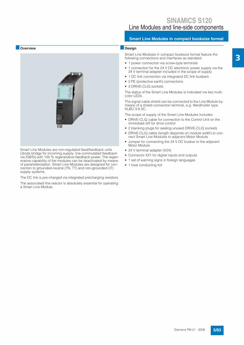
Smart Line Modules are non-regulated feed/feedback units (diode bridge for incoming supply; line-commutated feedback via IGBTs) with 100 % regenerative feedback power. The regen-erative capability of the modules can be deactivated by means of parameterization. Smart Line Modules are designed for con-nection to grounded-neutral (TN, TT) and non-grounded (IT) supply systems.
The DC link is pre-charged via integrated precharging resistors.
The associated line reactor is absolutely essential for operating a Smart Line Module.
■ Design
Smart Line Modules in compact booksize format feature the following connections and interfaces as standard:• 1 power connection via screw-type terminals• 1 connection for the 24 V DC electronic power supply via the
24 V terminal adapter included in the scope of supply• 1 DC link connection via integrated DC link busbars• 2 PE (protective earth) connections• 3 DRIVE-CLiQ sockets
The status of the Smart Line Modules is indicated via two multi-color LEDs.
The signal cable shield can be connected to the Line Module by means of a shield connection terminal, e.g. Weidmüller type KLBÜ 3-8 SC.
The scope of supply of the Smart Line Modules includes:• DRIVE-CLiQ cable for connection to the Control Unit on the
immediate left for drive control• 2 blanking plugs for sealing unused DRIVE-CLiQ sockets• DRIVE-CLiQ cable (length depends on module width) to con-
nect Smart Line Modules to adjacent Motor Module• Jumper for connecting the 24 V DC busbar to the adjacent
Motor Module• 24 V terminal adapter (X24)• Connector X21 for digital inputs and outputs• 1 set of warning signs in foreign languages• 1 heat conducting foil
SINAMICS S120Line Modules and line-side components
Smart Line Modules in compact booksize format
3/84 Siemens PM 21 · 2008
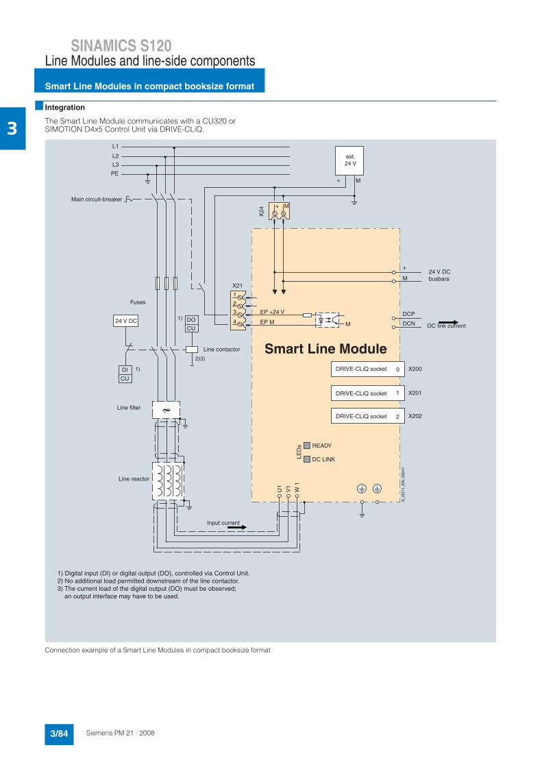
3■ Integration
The Smart Line Module communicates with a CU320 or SIMOTION D4x5 Control Unit via DRIVE-CLiQ.
Connection example of a Smart Line Modules in compact booksize format
X202
1 X201
2
0 X200
L3
L2
L1
PE
EP +24 V
X21
4
3
2
1
EP M
U1
V1
W 1
DO
CU
1)
+ M
+ M
X24
Smart Line Module2)3)
DI
CU
M
DCP
+
DCN
1)
READY
LED
s
DC LINK
M
DRIVE-CLiQ socket
DRIVE-CLiQ socket
DRIVE-CLiQ socket
Main circuit-breaker
Fuses
Line contactor
G_D
211_
EN
_000
41
Line filter
Line reactor
ext. 24 V
1) Digital input (DI) or digital output (DO), controlled via Control Unit. 2) No additional load permitted downstream of the line contactor. 3) The current load of the digital output (DO) must be observed; an output interface may have to be used.
24 V DC
24 V DC busbars
DC link current
Input current
SINAMICS S120Line Modules and line-side components
Smart Line Modules in compact booksize format
3/85Siemens PM 21 · 2008
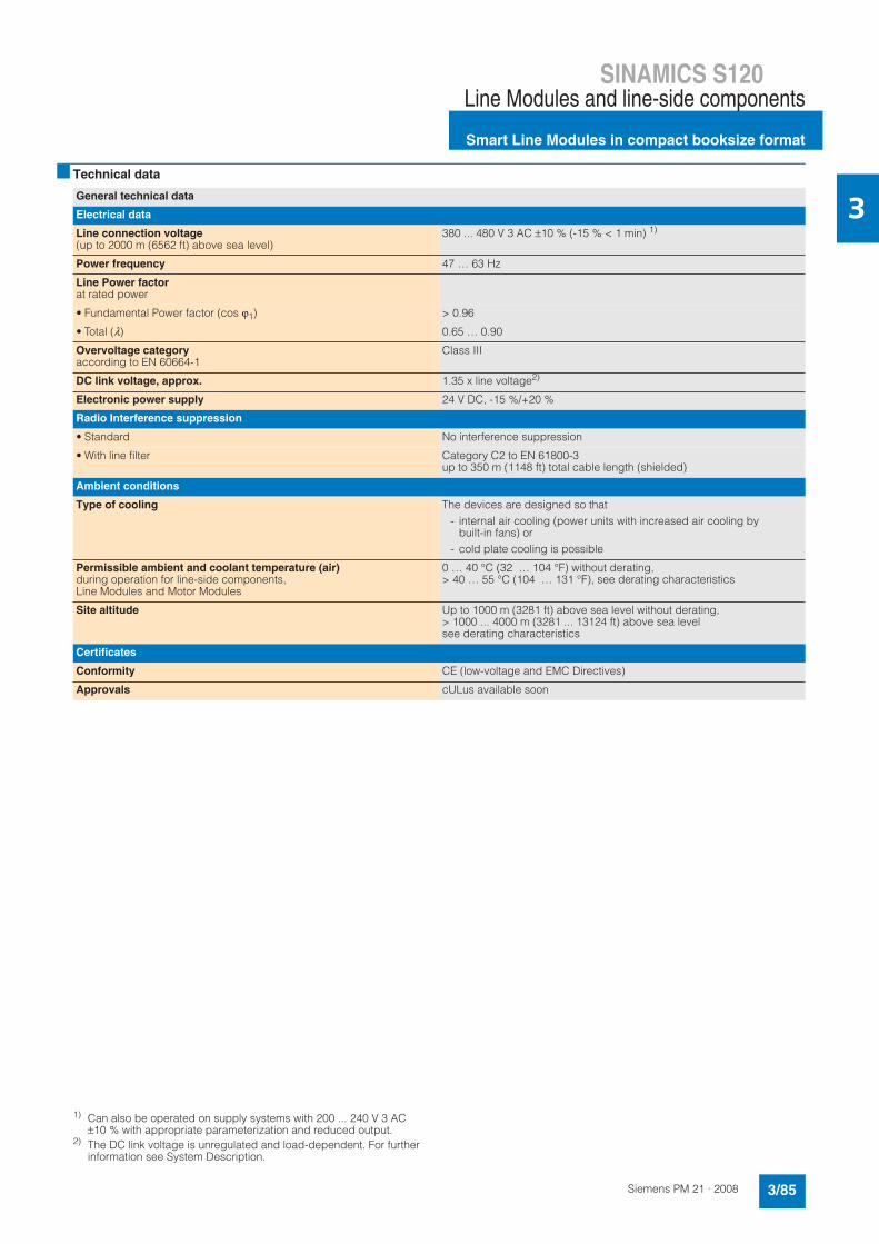
3■ Technical data
1) Can also be operated on supply systems with 200 ... 240 V 3 AC ±10 % with appropriate parameterization and reduced output.
2) The DC link voltage is unregulated and load-dependent. For further information see System Description.
General technical data
Electrical data
Line connection voltage(up to 2000 m (6562 ft) above sea level)
380 ... 480 V 3 AC ±10 % (-15 % < 1 min) 1)
Power frequency 47 … 63 Hz
Line Power factorat rated power
• Fundamental Power factor (cos ϕ1) > 0.96
• Total (λ) 0.65 … 0.90
Overvoltage categoryaccording to EN 60664-1
Class III
DC link voltage, approx. 1.35 x line voltage2)
Electronic power supply 24 V DC, -15 %/+20 %
Radio Interference suppression
• Standard No interference suppression
• With line filter Category C2 to EN 61800-3up to 350 m (1148 ft) total cable length (shielded)
Ambient conditions
Type of cooling The devices are designed so that- internal air cooling (power units with increased air cooling by
built-in fans) or- cold plate cooling is possible
Permissible ambient and coolant temperature (air)during operation for line-side components, Line Modules and Motor Modules
0 … 40 °C (32 … 104 °F) without derating,> 40 … 55 °C (104 … 131 °F), see derating characteristics
Site altitude Up to 1000 m (3281 ft) above sea level without derating,> 1000 ... 4000 m (3281 ... 13124 ft) above sea level see derating characteristics
Certificates
Conformity CE (low-voltage and EMC Directives)
Approvals cULus available soon
SINAMICS S120Line Modules and line-side components
Smart Line Modules in compact booksize format
3/86 Siemens PM 21 · 2008
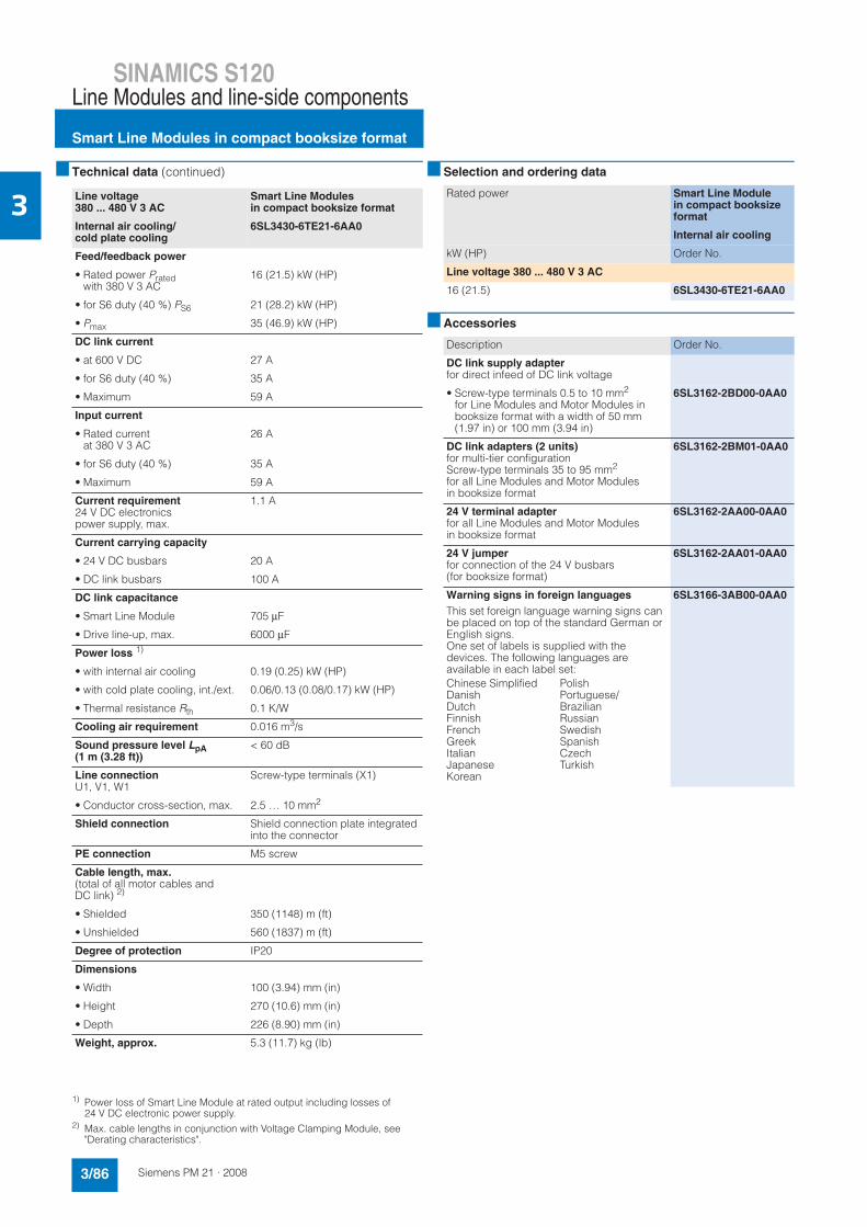
3■ Technical data (continued)
1) Power loss of Smart Line Module at rated output including losses of 24 V DC electronic power supply.
2) Max. cable lengths in conjunction with Voltage Clamping Module, see "Derating characteristics".
■ Selection and ordering data
■ Accessories
Line voltage 380 ... 480 V 3 AC
Smart Line Modules in compact booksize format
Internal air cooling/cold plate cooling
6SL3430-6TE21-6AA0
Feed/feedback power
• Rated power Pratedwith 380 V 3 AC
16 (21.5) kW (HP)
• for S6 duty (40 %) PS6 21 (28.2) kW (HP)
• Pmax 35 (46.9) kW (HP)
DC link current
• at 600 V DC 27 A
• for S6 duty (40 %) 35 A
• Maximum 59 A
Input current
• Rated current at 380 V 3 AC
26 A
• for S6 duty (40 %) 35 A
• Maximum 59 A
Current requirement24 V DC electronicspower supply, max.
1.1 A
Current carrying capacity
• 24 V DC busbars 20 A
• DC link busbars 100 A
DC link capacitance
• Smart Line Module 705 μF
• Drive line-up, max. 6000 μF
Power loss 1)
• with internal air cooling 0.19 (0.25) kW (HP)
• with cold plate cooling, int./ext. 0.06/0.13 (0.08/0.17) kW (HP)
• Thermal resistance Rth 0.1 K/W
Cooling air requirement 0.016 m3/s
Sound pressure level LpA(1 m (3.28 ft))
< 60 dB
Line connectionU1, V1, W1
Screw-type terminals (X1)
• Conductor cross-section, max. 2.5 … 10 mm2
Shield connection Shield connection plate integrated into the connector
PE connection M5 screw
Cable length, max.(total of all motor cables and DC link) 2)
• Shielded 350 (1148) m (ft)
• Unshielded 560 (1837) m (ft)
Degree of protection IP20
Dimensions
• Width 100 (3.94) mm (in)
• Height 270 (10.6) mm (in)
• Depth 226 (8.90) mm (in)
Weight, approx. 5.3 (11.7) kg (lb)
Rated power Smart Line Modulein compact booksize format
Internal air cooling
kW (HP) Order No.
Line voltage 380 ... 480 V 3 AC
16 (21.5) 6SL3430-6TE21-6AA0
Description Order No.
DC link supply adapterfor direct infeed of DC link voltage
• Screw-type terminals 0.5 to 10 mm2
for Line Modules and Motor Modules in booksize format with a width of 50 mm (1.97 in) or 100 mm (3.94 in)
6SL3162-2BD00-0AA0
DC link adapters (2 units)for multi-tier configurationScrew-type terminals 35 to 95 mm2
for all Line Modules and Motor Modules in booksize format
6SL3162-2BM01-0AA0
24 V terminal adapterfor all Line Modules and Motor Modules in booksize format
6SL3162-2AA00-0AA0
24 V jumperfor connection of the 24 V busbars(for booksize format)
6SL3162-2AA01-0AA0
Warning signs in foreign languages
This set foreign language warning signs can be placed on top of the standard German or English signs.One set of labels is supplied with the devices. The following languages are available in each label set:
6SL3166-3AB00-0AA0
Chinese SimplifiedDanishDutchFinnishFrenchGreekItalianJapaneseKorean
PolishPortuguese/BrazilianRussianSwedishSpanishCzechTurkish
SINAMICS S120Line Modules and line-side components
Smart Line Modules in compact booksize format
3/87Siemens PM 21 · 2008
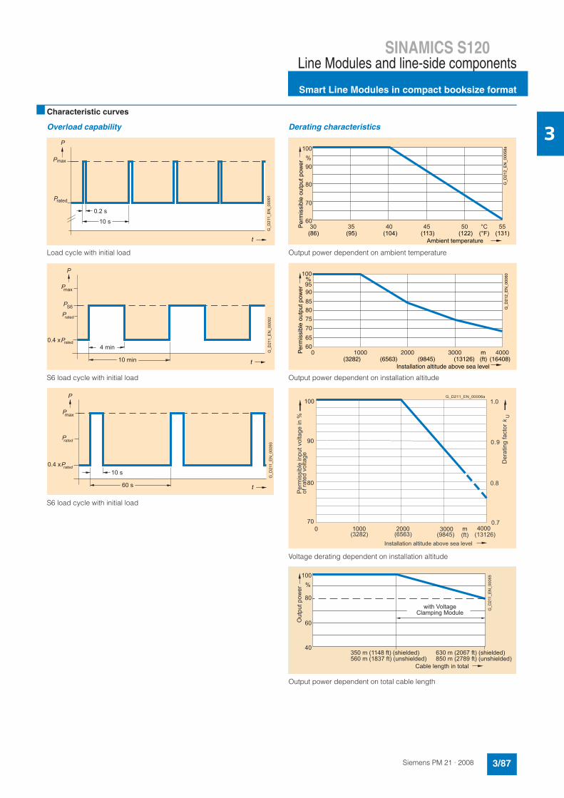
3■ Characteristic curves
Overload capability
Load cycle with initial load
S6 load cycle with initial load
S6 load cycle with initial load
Derating characteristics
Output power dependent on ambient temperature
Output power dependent on installation altitude
Voltage derating dependent on installation altitude
Output power dependent on total cable length
max
10 s
t
P
P
Prated
0.2 s
G_D
211_
EN
_000
91
4 min
max
P
P
S6P
P
10 min t
0.4 x rated
rated
G_D
211_
EN
_000
92
P
10 s
max
P
P
P
60 s t
P
0.4 x rated
G_D
211_
EN
_000
93 rated
Per
mis
sibl
e ou
tput
pow
er
Ambient temperature
G_D
212_
EN
_000
58a
(86) (95) (104) (113) (122) (131)(°F)
100
90
80
70
6030 35 40 45 50 55
%
°C
Per
mis
sibl
e ou
tput
pow
er
Installation altitude above sea level
%
m
G_D
212_
EN
_000
60
(ft)(3282) (6563) (9845) (13126) (16408)
100
9590
8580
75
0 1000 2000 3000 4000
70
65
60
Per
mis
sibl
e in
put v
olta
ge in
%of
rate
d vo
ltage
G_D211_EN_00006a
(3282) (6563) (9845) (ft) (13126)
1.0
0.9
0.7
0.8
Installation altitude above sea level
Der
atin
g fa
ctor
kU
1000 2000 m0 3000 4000
100
90
80
70
100
80
60
40
%
Out
put p
ower
G_D
211_
EN
_000
65
with Voltage Clamping Module
350 m (1148 ft) (shielded)560 m (1837 ft) (unshielded)
Cable length in total
630 m (2067 ft) (shielded)850 m (2789 ft) (unshielded)
SINAMICS S120Line Modules and line-side components
Smart Line Modules in booksize formatLine reactors
3/95Siemens PM 21 · 2008
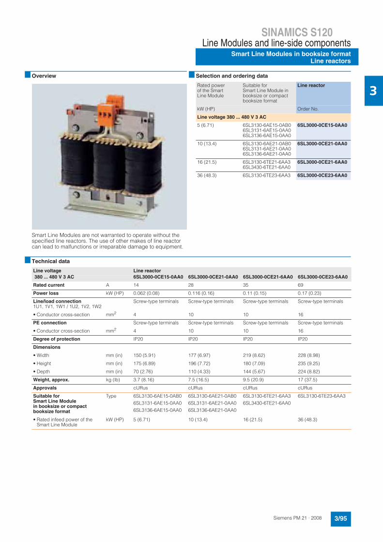
3■ Overview
Smart Line Modules are not warranted to operate without the specified line reactors. The use of other makes of line reactor can lead to malfunctions or irreparable damage to equipment.
■ Selection and ordering data
■ Technical data
Rated power of the Smart Line Module
Suitable for Smart Line Module in booksize or compact booksize format
Line reactor
kW (HP) Order No.
Line voltage 380 ... 480 V 3 AC
5 (6.71) 6SL3130-6AE15-0AB06SL3131-6AE15-0AA06SL3136-6AE15-0AA0
6SL3000-0CE15-0AA0
10 (13.4) 6SL3130-6AE21-0AB06SL3131-6AE21-0AA06SL3136-6AE21-0AA0
6SL3000-0CE21-0AA0
16 (21.5) 6SL3130-6TE21-6AA36SL3430-6TE21-6AA0
6SL3000-0CE21-6AA0
36 (48.3) 6SL3130-6TE23-6AA3 6SL3000-0CE23-6AA0
Line voltage Line reactor
380 ... 480 V 3 AC 6SL3000-0CE15-0AA0 6SL3000-0CE21-0AA0 6SL3000-0CE21-6AA0 6SL3000-0CE23-6AA0
Rated current A 14 28 35 69
Power loss kW (HP) 0.062 (0.08) 0.116 (0.16) 0.11 (0.15) 0.17 (0.23)
Line/load connection1U1, 1V1, 1W1 / 1U2, 1V2, 1W2
Screw-type terminals Screw-type terminals Screw-type terminals Screw-type terminals
• Conductor cross-section mm2 4 10 10 16
PE connection Screw-type terminals Screw-type terminals Screw-type terminals Screw-type terminals
• Conductor cross-section mm2 4 10 10 16
Degree of protection IP20 IP20 IP20 IP20
Dimensions
• Width mm (in) 150 (5.91) 177 (6.97) 219 (8.62) 228 (8.98)
• Height mm (in) 175 (6.89) 196 (7.72) 180 (7.09) 235 (9.25)
• Depth mm (in) 70 (2.76) 110 (4.33) 144 (5.67) 224 (8.82)
Weight, approx. kg (lb) 3.7 (8.16) 7.5 (16.5) 9.5 (20.9) 17 (37.5)
Approvals cURus cURus cURus cURus
Suitable for Smart Line Modulein booksize or compact booksize format
Type 6SL3130-6AE15-0AB06SL3131-6AE15-0AA06SL3136-6AE15-0AA0
6SL3130-6AE21-0AB06SL3131-6AE21-0AA06SL3136-6AE21-0AA0
6SL3130-6TE21-6AA36SL3430-6TE21-6AA0
6SL3130-6TE23-6AA3
• Rated infeed power of the Smart Line Module
kW (HP) 5 (6.71) 10 (13.4) 16 (21.5) 36 (48.3)
SINAMICS S120Line Modules and line-side componentsSmart Line Modules in booksize formatLine filters
3/96 Siemens PM 21 · 2008
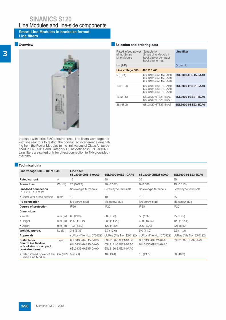
3■ Overview
In plants with strict EMC requirements, line filters work together with line reactors to restrict the conducted interference emanat-ing from the Power Modules to the limit values of Class A1 as de-fined in EN 55011 and Category C2 as defined in EN 61800-3. Line filters are suited only for direct connection to TN (grounded) systems.
■ Selection and ordering data
■ Technical data
Rated infeed power of the Smart Line Module
Suitable for Smart Line Module in booksize or compact booksize format
Line filter
kW (HP) Order No.
Line voltage 380 ... 480 V 3 AC
5 (6.71) 6SL3130-6AE15-0AB06SL3131-6AE15-0AA06SL3136-6AE15-0AA0
6SL3000-0HE15-0AA0
10 (13.4) 6SL3130-6AE21-0AB06SL3131-6AE21-0AA06SL3136-6AE21-0AA0
6SL3000-0HE21-0AA0
16 (21.5) 6SL3130-6TE21-6AA36SL3430-6TE21-6AA0
6SL3000-0BE21-6DA0
36 (48.3) 6SL3130-6TE23-6AA3 6SL3000-0BE23-6DA0
Line voltage 380 ... 480 V 3 AC Line filter
6SL3000-0HE15-0AA0 6SL3000-0HE21-0AA0 6SL3000-0BE21-6DA0 6SL3000-0BE23-6DA0
Rated current A 16 25 36 65
Power loss W (HP) 20 (0.027) 20 (0.027) 6 (0.008) 10 (0.013)
Line/load connectionL1, L2, L3 / U, V, W
Screw-type terminals Screw-type terminals Screw-type terminals Screw-type terminals
• Conductor cross-section mm2 10 10 10 35
PE connection M6 screw stud M6 screw stud M6 screw stud M6 screw stud
Degree of protection IP20 IP20 IP20 IP20
Dimensions
• Width mm (in) 60 (2.36) 60 (2.36) 50 (1.97) 75 (2.95)
• Height mm (in) 285 (11.22) 285 (11.22) 420 (16.54) 420 (16.54)
• Depth mm (in) 122 (4.80) 122 (4.80) 226 (8.90) 226 (8.90)
Weight, approx. kg (lb) 3.8 (8.38) 5.7 (12.6) 5.0 (11.0) 6.5 (14.3)
Approvals cURus (File No.: E70122) cURus (File No.: E70122) cURus (File No.: E70122) cURus (File No.: E70122)
Suitable for Smart Line Module in booksize or compact booksize format
Type 6SL3130-6AE15-0AB06SL3131-6AE15-0AA06SL3136-6AE15-0AA0
6SL3130-6AE21-0AB06SL3131-6AE21-0AA06SL3136-6AE21-0AA0
6SL3130-6TE21-6AA36SL3430-6TE21-6AA0
6SL3130-6TE23-6AA3
• Rated infeed power of the Smart Line Module
kW (HP) 5 (6.71) 10 (13.4) 16 (21.5) 36 (48.3)
SINAMICS S120Line Modules and line-side components
Smart Line Modules in booksize formatRecommended line-side components
3/97Siemens PM 21 · 2008
3■ Overview
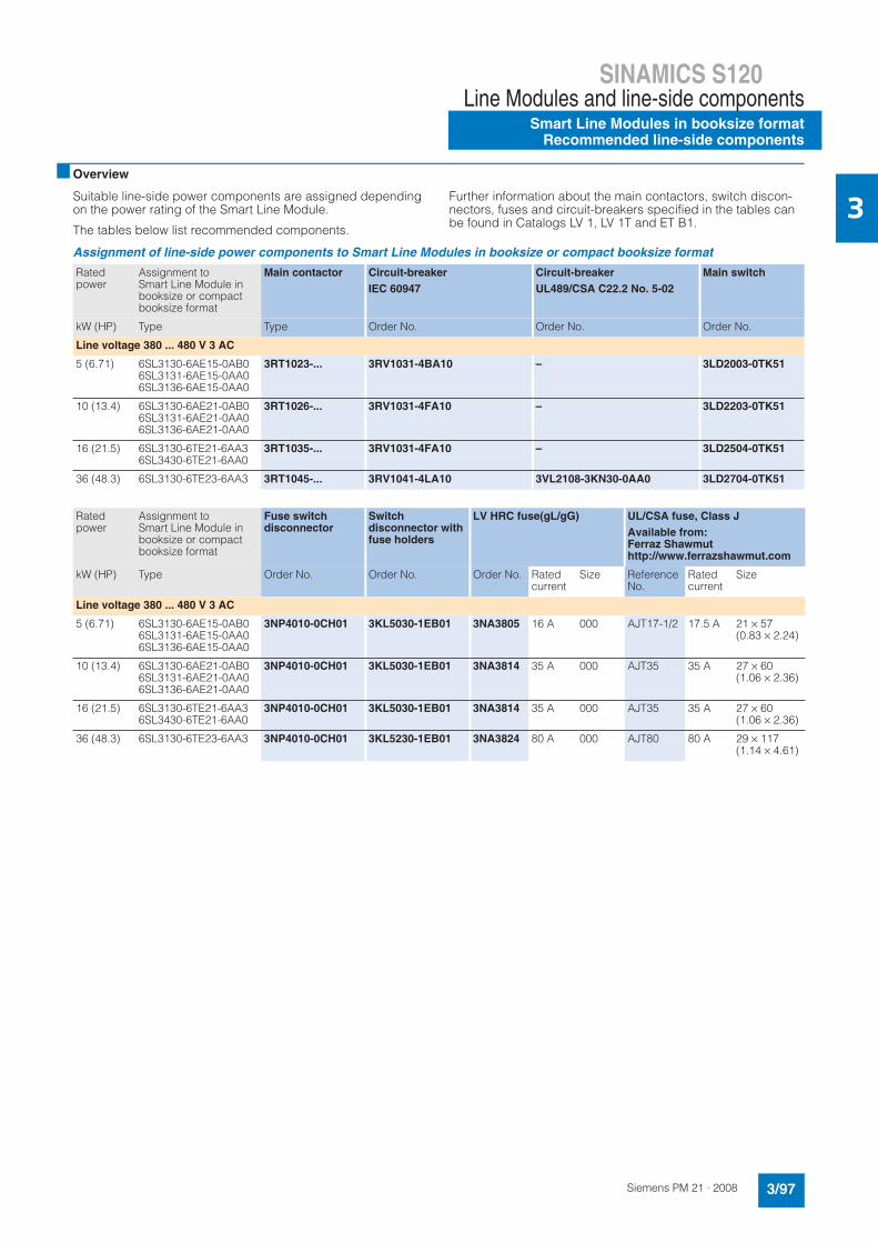
Suitable line-side power components are assigned depending on the power rating of the Smart Line Module.
The tables below list recommended components.
Further information about the main contactors, switch discon-nectors, fuses and circuit-breakers specified in the tables can be found in Catalogs LV 1, LV 1T and ET B1.
Assignment of line-side power components to Smart Line Modules in booksize or compact booksize format
Ratedpower
Assignment to Smart Line Module in booksize or compact booksize format
Main contactor Circuit-breaker
IEC 60947
Circuit-breaker
UL489/CSA C22.2 No. 5-02
Main switch
kW (HP) Type Type Order No. Order No. Order No.
Line voltage 380 ... 480 V 3 AC
5 (6.71) 6SL3130-6AE15-0AB06SL3131-6AE15-0AA06SL3136-6AE15-0AA0
3RT1023-... 3RV1031-4BA10 – 3LD2003-0TK51
10 (13.4) 6SL3130-6AE21-0AB06SL3131-6AE21-0AA06SL3136-6AE21-0AA0
3RT1026-... 3RV1031-4FA10 – 3LD2203-0TK51
16 (21.5) 6SL3130-6TE21-6AA36SL3430-6TE21-6AA0
3RT1035-... 3RV1031-4FA10 – 3LD2504-0TK51
36 (48.3) 6SL3130-6TE23-6AA3 3RT1045-... 3RV1041-4LA10 3VL2108-3KN30-0AA0 3LD2704-0TK51
Ratedpower
Assignment to Smart Line Module in booksize or compact booksize format
Fuse switch disconnector
Switchdisconnector with fuse holders
LV HRC fuse(gL/gG) UL/CSA fuse, Class J
Available from:Ferraz Shawmuthttp://www.ferrazshawmut.com
kW (HP) Type Order No. Order No. Order No. Rated current
Size Reference No.
Ratedcurrent
Size
Line voltage 380 ... 480 V 3 AC
5 (6.71) 6SL3130-6AE15-0AB06SL3131-6AE15-0AA06SL3136-6AE15-0AA0
3NP4010-0CH01 3KL5030-1EB01 3NA3805 16 A 000 AJT17-1/2 17.5 A 21 × 57 (0.83 × 2.24)
10 (13.4) 6SL3130-6AE21-0AB06SL3131-6AE21-0AA06SL3136-6AE21-0AA0
3NP4010-0CH01 3KL5030-1EB01 3NA3814 35 A 000 AJT35 35 A 27 × 60 (1.06 × 2.36)
16 (21.5) 6SL3130-6TE21-6AA36SL3430-6TE21-6AA0
3NP4010-0CH01 3KL5030-1EB01 3NA3814 35 A 000 AJT35 35 A 27 × 60 (1.06 × 2.36)
36 (48.3) 6SL3130-6TE23-6AA3 3NP4010-0CH01 3KL5230-1EB01 3NA3824 80 A 000 AJT80 80 A 29 × 117 (1.14 × 4.61)
SINAMICS S120Motor ModulesSingle Motor Modulesin compact booksize format
3/136 Siemens PM 21 · 2008
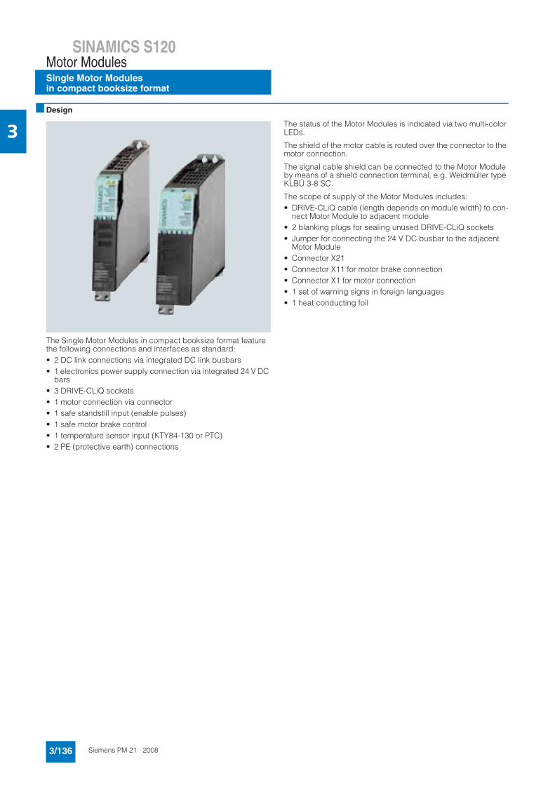
3■ Design
The Single Motor Modules in compact booksize format feature the following connections and interfaces as standard:• 2 DC link connections via integrated DC link busbars• 1 electronics power supply connection via integrated 24 V DC
bars• 3 DRIVE-CLiQ sockets• 1 motor connection via connector• 1 safe standstill input (enable pulses)• 1 safe motor brake control• 1 temperature sensor input (KTY84-130 or PTC)• 2 PE (protective earth) connections
The status of the Motor Modules is indicated via two multi-color LEDs.
The shield of the motor cable is routed over the connector to the motor connection.
The signal cable shield can be connected to the Motor Module by means of a shield connection terminal, e.g. Weidmüller type KLBÜ 3-8 SC.
The scope of supply of the Motor Modules includes:• DRIVE-CLiQ cable (length depends on module width) to con-
nect Motor Module to adjacent module• 2 blanking plugs for sealing unused DRIVE-CLiQ sockets• Jumper for connecting the 24 V DC busbar to the adjacent
Motor Module• Connector X21• Connector X11 for motor brake connection• Connector X1 for motor connection• 1 set of warning signs in foreign languages• 1 heat conducting foil
SINAMICS S120Motor Modules
Single Motor Modulesin compact booksize format
3/137Siemens PM 21 · 2008
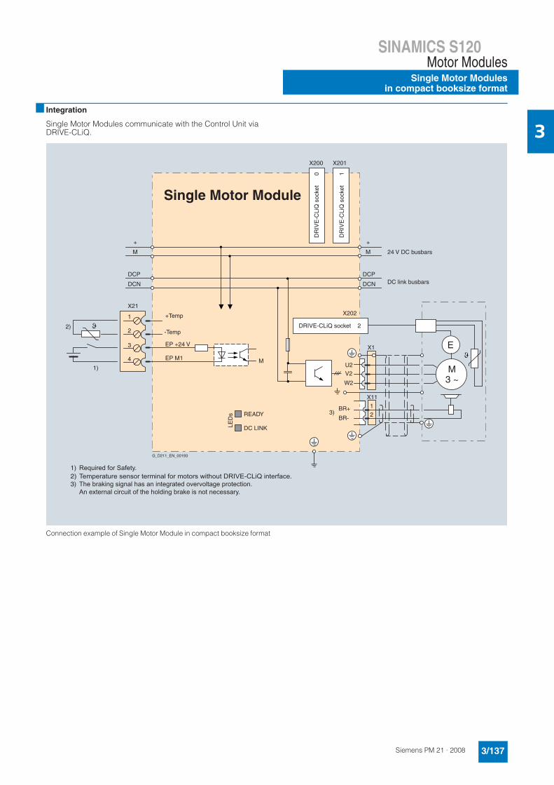
3■ Integration
Single Motor Modules communicate with the Control Unit via DRIVE-CLiQ.
Connection example of Single Motor Module in compact booksize format
X201X200
+Temp
X21
EP M1
EP +24 V
BR+
BR-
X202
4
3
2
1
M3 ~
E
U2V2
X11
M
+
DCN
DCP
M
+
DCN
DCP
Single Motor Module
1)
1
2
W2
READY
LED
s
DC LINK
2)
3)
M
-Temp
X1
G_D211_EN_00193
DC link busbars
24 V DC busbars
DRIVE-CLiQ socket 2
DR
IVE
-CLi
Q s
ocke
t
0
DR
IVE
-CLi
Q s
ocke
t
1
Required for Safety.Temperature sensor terminal for motors without DRIVE-CLiQ interface.The braking signal has an integrated overvoltage protection.An external circuit of the holding brake is not necessary.
1)2)3)

SINAMICS S120Motor ModulesSingle Motor Modulesin compact booksize format
3/138 Siemens PM 21 · 2008
3■ Technical data
1) With firmware version V2.5 and higher with appropriate parameteriza-tion and reduced output also operable on 200 ... 240 V 3 AC networks in accordance with a DC-link voltage of 270 ... 360 V DC.
2) Note correlation between max. output frequency, pulse frequency and current derating, see System Description.
General technical data
Electrical data
DC link voltage(up to 2000 m (6562 ft) above sea level)
510 ... 720 V DC(line voltage 380 ... 480 V 3 AC) 1)
Output frequency
• Control type Servo 0 … 650 Hz 2)
• Control type Vector 0 … 300 Hz 2)
• Control type V/f 0 … 600 Hz 2)
Electronics power supply 24 V DC -15 %/+20 %
Ambient conditions
Type of cooling The devices are designed so that- internal air cooling (power units with increased air cooling
by built-in fans) or- cold plate cooling is possible.
Permissible ambient and coolant temperature (air)during operation for line-side components, Line Modules and Motor Modules
0 … 40 °C (32 … 104 °F) without derating,> 40 … 55 °C (104 … 131 °F), see derating characteristics
Site altitude Up to 1000 m (3281 ft) above sea level without derating,> 1000 ... 4000 m (3281 ... 13124 ft) above sea level see derating characteristics
Certificates
Conformity CE (low-voltage and EMC Directives)
Approvals cULus available soon
Safety Integrated Safety Integrity Level 2 (SIL 2) to IEC 61508,control category 3 to EN 954-1For further information, see the Safety Integrated section
SINAMICS S120Motor Modules
Single Motor Modulesin compact booksize format
3/139Siemens PM 21 · 2008
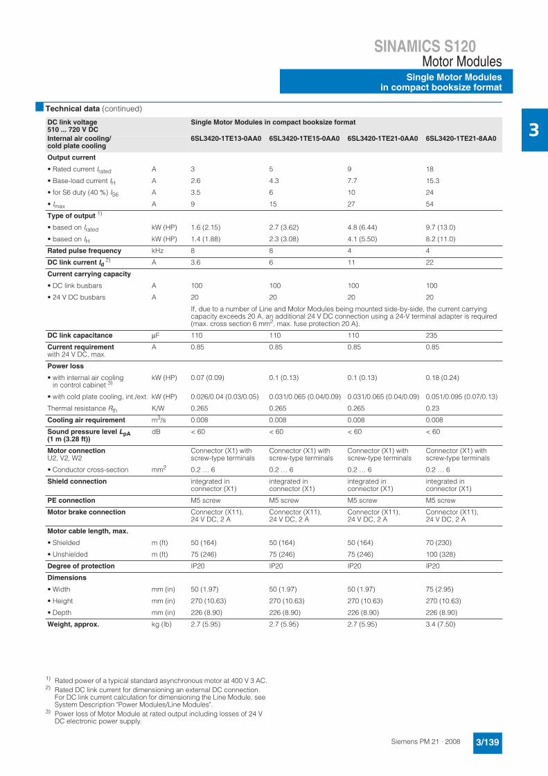
3■ Technical data (continued)
1) Rated power of a typical standard asynchronous motor at 400 V 3 AC.2) Rated DC link current for dimensioning an external DC connection.
For DC link current calculation for dimensioning the Line Module, see System Description "Power Modules/Line Modules".
3) Power loss of Motor Module at rated output including losses of 24 V DC electronic power supply.
DC link voltage 510 ... 720 V DC
Single Motor Modules in compact booksize format
Internal air cooling/cold plate cooling
6SL3420-1TE13-0AA0 6SL3420-1TE15-0AA0 6SL3420-1TE21-0AA0 6SL3420-1TE21-8AA0
Output current
• Rated current Irated A 3 5 9 18
• Base-load current IH A 2.6 4.3 7.7 15.3
• for S6 duty (40 %) IS6 A 3.5 6 10 24
• Imax A 9 15 27 54
Type of output 1)
• based on Irated kW (HP) 1.6 (2.15) 2.7 (3.62) 4.8 (6.44) 9.7 (13.0)
• based on IH kW (HP) 1.4 (1.88) 2.3 (3.08) 4.1 (5.50) 8.2 (11.0)
Rated pulse frequency kHz 8 8 4 4
DC link current Id2) A 3.6 6 11 22
Current carrying capacity
• DC link busbars A 100 100 100 100
• 24 V DC busbars A 20 20 20 20
If, due to a number of Line and Motor Modules being mounted side-by-side, the current carrying capacity exceeds 20 A, an additional 24 V DC connection using a 24-V terminal adapter is required (max. cross section 6 mm2, max. fuse protection 20 A).
DC link capacitance μF 110 110 110 235
Current requirementwith 24 V DC, max.
A 0.85 0.85 0.85 0.85
Power loss
• with internal air cooling in control cabinet 3)
kW (HP) 0.07 (0.09) 0.1 (0.13) 0.1 (0.13) 0.18 (0.24)
• with cold plate cooling, int./ext. kW (HP) 0.026/0.04 (0.03/0.05) 0.031/0.065 (0.04/0.09) 0.031/0.065 (0.04/0.09) 0.051/0.095 (0.07/0.13)
Thermal resistance Rth K/W 0.265 0.265 0.265 0.23
Cooling air requirement m3/s 0.008 0.008 0.008 0.008
Sound pressure level LpA(1 m (3.28 ft))
dB < 60 < 60 < 60 < 60
Motor connectionU2, V2, W2
Connector (X1) with screw-type terminals
Connector (X1) with screw-type terminals
Connector (X1) with screw-type terminals
Connector (X1) with screw-type terminals
• Conductor cross-section mm2 0.2 … 6 0.2 … 6 0.2 … 6 0.2 … 6
Shield connection integrated in connector (X1)
integrated in connector (X1)
integrated in connector (X1)
integrated in connector (X1)
PE connection M5 screw M5 screw M5 screw M5 screw
Motor brake connection Connector (X11), 24 V DC, 2 A
Connector (X11), 24 V DC, 2 A
Connector (X11), 24 V DC, 2 A
Connector (X11), 24 V DC, 2 A
Motor cable length, max.
• Shielded m (ft) 50 (164) 50 (164) 50 (164) 70 (230)
• Unshielded m (ft) 75 (246) 75 (246) 75 (246) 100 (328)
Degree of protection IP20 IP20 IP20 IP20
Dimensions
• Width mm (in) 50 (1.97) 50 (1.97) 50 (1.97) 75 (2.95)
• Height mm (in) 270 (10.63) 270 (10.63) 270 (10.63) 270 (10.63)
• Depth mm (in) 226 (8.90) 226 (8.90) 226 (8.90) 226 (8.90)
Weight, approx. kg (lb) 2.7 (5.95) 2.7 (5.95) 2.7 (5.95) 3.4 (7.50)
SINAMICS S120Motor ModulesSingle Motor Modulesin compact booksize format
3/140 Siemens PM 21 · 2008
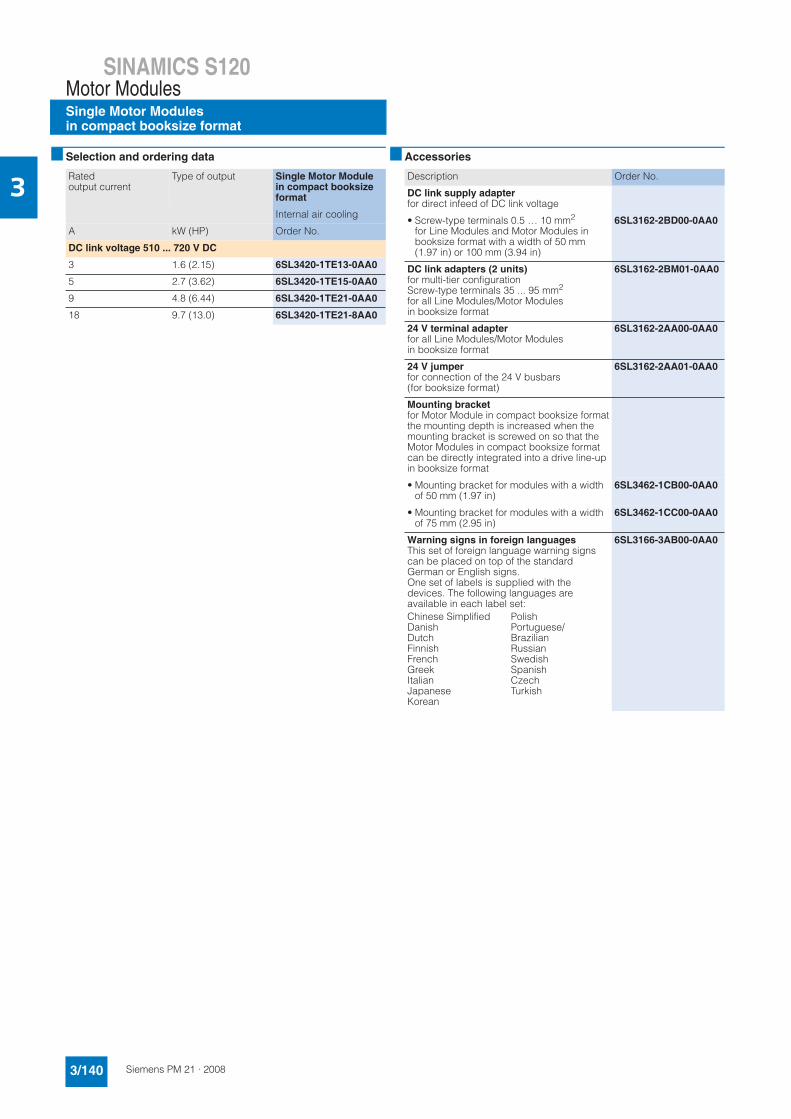
3■ Selection and ordering data ■ Accessories
Ratedoutput current
Type of output Single Motor Module in compact booksize format
Internal air cooling
A kW (HP) Order No.
DC link voltage 510 ... 720 V DC
3 1.6 (2.15) 6SL3420-1TE13-0AA0
5 2.7 (3.62) 6SL3420-1TE15-0AA0
9 4.8 (6.44) 6SL3420-1TE21-0AA0
18 9.7 (13.0) 6SL3420-1TE21-8AA0
Description Order No.
DC link supply adapterfor direct infeed of DC link voltage
• Screw-type terminals 0.5 … 10 mm2
for Line Modules and Motor Modules in booksize format with a width of 50 mm (1.97 in) or 100 mm (3.94 in)
6SL3162-2BD00-0AA0
DC link adapters (2 units)for multi-tier configurationScrew-type terminals 35 ... 95 mm2
for all Line Modules/Motor Modules in booksize format
6SL3162-2BM01-0AA0
24 V terminal adapterfor all Line Modules/Motor Modules in booksize format
6SL3162-2AA00-0AA0
24 V jumperfor connection of the 24 V busbars(for booksize format)
6SL3162-2AA01-0AA0
Mounting bracketfor Motor Module in compact booksize formatthe mounting depth is increased when the mounting bracket is screwed on so that the Motor Modules in compact booksize format can be directly integrated into a drive line-up in booksize format
• Mounting bracket for modules with a width of 50 mm (1.97 in)
6SL3462-1CB00-0AA0
• Mounting bracket for modules with a width of 75 mm (2.95 in)
6SL3462-1CC00-0AA0
Warning signs in foreign languagesThis set of foreign language warning signs can be placed on top of the standard German or English signs.One set of labels is supplied with the devices. The following languages are available in each label set:
6SL3166-3AB00-0AA0
Chinese SimplifiedDanishDutchFinnishFrenchGreekItalianJapaneseKorean
PolishPortuguese/BrazilianRussianSwedishSpanishCzechTurkish
SINAMICS S120Motor Modules
Single Motor Modulesin compact booksize format
3/141Siemens PM 21 · 2008
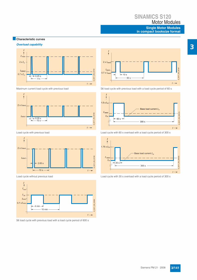
3■ Characteristic curves
Overload capability
Maximum current load cycle with previous load
Load cycle with previous load
Load cycle without previous load
S6 load cycle with previous load with a load cycle period of 600 s
S6 load cycle with previous load with a load cycle period of 60 s
Load cycle with 60 s overload with a load cycle period of 300 s
Load cycle with 30 s overload with a load cycle period of 300 s
max
4 s
t
Irated
0.25 s
G_D
211_
EN
_001
94
n
n0.7 x
2 x
10 s
t
Irated0.25 s
G_D
211_
EN
_001
95
2 x Irated
10 s t
G_D
211_
EN
_001
96Irated
2.65 s
2 x Irated
4 min
max
S6
10 min
t
0.7 x rated
rated
G_D
211_
EN
_000
84
10 s60 s
t
2 x Irated
G_D
211_
EN
_001
97
0.7 x IratedIrated
60 s 300 s
t
H
H
1.5 x
Base load current H
rated
G_D
211_
EN
_000
01b
30 s300 s
t
H
H1.76 x
Base load current
rated
H
G_D
211_
EN
_000
02b
SINAMICS S120Motor ModulesSingle Motor Modulesin compact booksize format
3/142 Siemens PM 21 · 2008
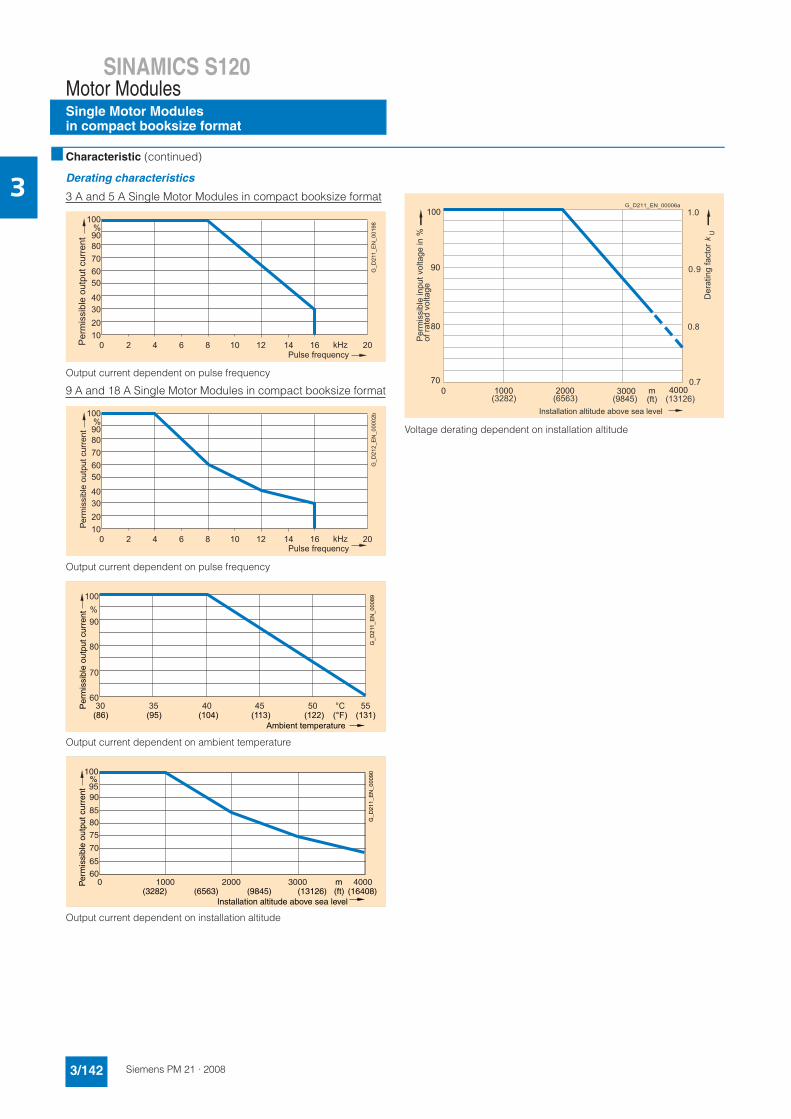
3■ Characteristic (continued)
Derating characteristics
3 A and 5 A Single Motor Modules in compact booksize format
Output current dependent on pulse frequency
9 A and 18 A Single Motor Modules in compact booksize format
Output current dependent on pulse frequency
Output current dependent on ambient temperature
Output current dependent on installation altitude
Voltage derating dependent on installation altitude
100
90 80 70 60 50
0 4 8 12 16 20
40 30 20 10
2 6 10 14
%
kHz Per
mis
sibl
e ou
tput
cur
rent
Pulse frequency
G_D
211_
EN
_001
98
100
90 80 70 60 50
0 4 8 12 16 20
40 30 20 10
2 6 10 14
%
kHz
P er m
issi
b le
outp
ut c
urre
nt
Pulse frequency
G_D
212_
EN
_000
02b
Per
mis
sibl
e ou
tput
cur
rent
Ambient temperature
G_D
211_
EN
_000
89
(86) (95) (104) (113) (122) (131)(°F)
100
90
80
70
6030 35 40 45 50 55
%
°C
100
9590
8580
75
0 1000 2000 3000 4000
70
65
60
Per
mis
sibl
e ou
tput
cur
rent
Installation altitude above sea level
%
m
G_D
211_
EN
_000
90
(ft)(3282) (6563) (9845) (13126) (16408)
Per
mis
sibl
e in
put v
olta
ge in
%of
rate
d vo
ltage
G_D211_EN_00006a
(3282) (6563) (9845) (ft) (13126)
1.0
0.9
0.7
0.8
Installation altitude above sea level
Der
atin
g fa
ctor
kU
1000 2000 m0 3000 4000
100
90
80
70
SINAMICS S120Motor ModulesDouble Motor Modulesin compact booksize format
3/164 Siemens PM 21 · 2008
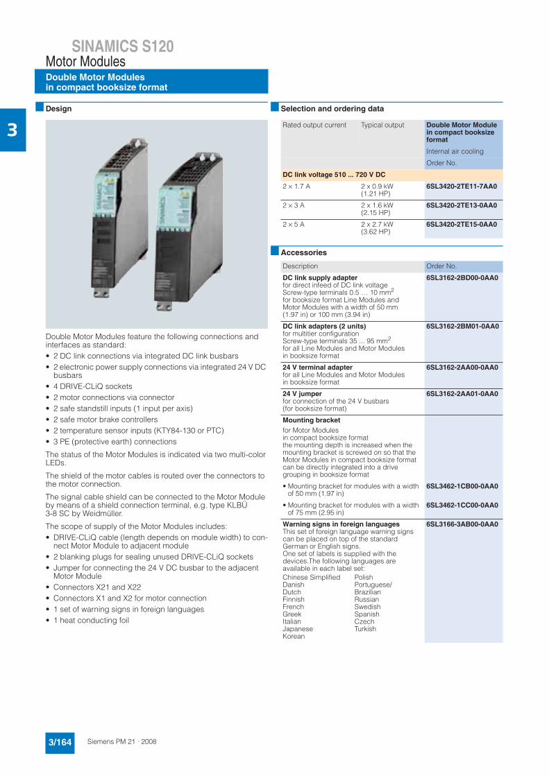
3■ Design
Double Motor Modules feature the following connections and interfaces as standard:• 2 DC link connections via integrated DC link busbars• 2 electronic power supply connections via integrated 24 V DC
busbars• 4 DRIVE-CLiQ sockets• 2 motor connections via connector• 2 safe standstill inputs (1 input per axis)• 2 safe motor brake controllers• 2 temperature sensor inputs (KTY84-130 or PTC)• 3 PE (protective earth) connections
The status of the Motor Modules is indicated via two multi-color LEDs.
The shield of the motor cables is routed over the connectors to the motor connection.
The signal cable shield can be connected to the Motor Module by means of a shield connection terminal, e.g. type KLBÜ3-8 SC by Weidmüller.
The scope of supply of the Motor Modules includes:• DRIVE-CLiQ cable (length depends on module width) to con-
nect Motor Module to adjacent module• 2 blanking plugs for sealing unused DRIVE-CLiQ sockets• Jumper for connecting the 24 V DC busbar to the adjacent
Motor Module• Connectors X21 and X22• Connectors X1 and X2 for motor connection• 1 set of warning signs in foreign languages• 1 heat conducting foil
■ Selection and ordering data
■ Accessories
Rated output current Typical output Double Motor Module in compact booksize format
Internal air cooling
Order No.
DC link voltage 510 ... 720 V DC
2 × 1.7 A 2 x 0.9 kW (1.21 HP)
6SL3420-2TE11-7AA0
2 × 3 A 2 x 1.6 kW (2.15 HP)
6SL3420-2TE13-0AA0
2 × 5 A 2 x 2.7 kW (3.62 HP)
6SL3420-2TE15-0AA0
Description Order No.
DC link supply adapterfor direct infeed of DC link voltageScrew-type terminals 0.5 … 10 mm2
for booksize format Line Modules and Motor Modules with a width of 50 mm (1.97 in) or 100 mm (3.94 in)
6SL3162-2BD00-0AA0
DC link adapters (2 units)for multitier configurationScrew-type terminals 35 ... 95 mm2
for all Line Modules and Motor Modules in booksize format
6SL3162-2BM01-0AA0
24 V terminal adapterfor all Line Modules and Motor Modules in booksize format
6SL3162-2AA00-0AA0
24 V jumperfor connection of the 24 V busbars(for booksize format)
6SL3162-2AA01-0AA0
Mounting bracket
for Motor Modules in compact booksize formatthe mounting depth is increased when the mounting bracket is screwed on so that the Motor Modules in compact booksize format can be directly integrated into a drive grouping in booksize format
• Mounting bracket for modules with a width of 50 mm (1.97 in)
6SL3462-1CB00-0AA0
• Mounting bracket for modules with a width of 75 mm (2.95 in)
6SL3462-1CC00-0AA0
Warning signs in foreign languagesThis set of foreign language warning signs can be placed on top of the standard German or English signs.One set of labels is supplied with the devices.The following languages are available in each label set:
6SL3166-3AB00-0AA0
Chinese SimplifiedDanishDutchFinnishFrenchGreekItalianJapaneseKorean
PolishPortuguese/BrazilianRussianSwedishSpanishCzechTurkish
SINAMICS S120Motor Modules
Double Motor Modulesin compact booksize format
3/165Siemens PM 21 · 2008
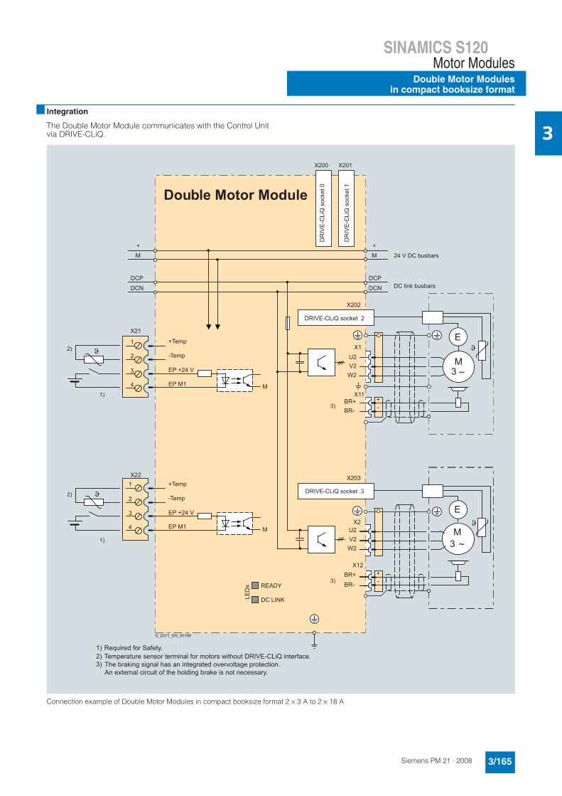
3■ Integration
The Double Motor Module communicates with the Control Unit via DRIVE-CLiQ.
Connection example of Double Motor Modules in compact booksize format 2 × 3 A to 2 × 18 A
X201 X200
X21
- +
U2 V2
BR+
W2
BR-
X202
X1
U2 V2
BR+
W2
BR-
X203
M 3
E X2
+TempX22
4
3
2
1
1)
1)
2)
2) -Temp
EP M1
EP +24 V
+Temp
-Temp
EP M1
EP +24 V
4
3
2
1
M 3
E
M +
DCN DCP
M +
DCN DCP
Double Motor Module
READY
LED
s
DC LINK
M
M
3)
3)
- +
X11
X12
G_D211_EN_00199
DRIVE-CLiQ socket 3
DRIVE-CLiQ socket 2 D
RIV
E-C
LiQ
soc
ket 0
DR
IVE
-CLi
Q s
ocke
t 1
DC link busbars
24 V DC busbars
Required for Safety.1)Temperature sensor terminal for motors without DRIVE-CLiQ interface.2)
3) The braking signal has an integrated overvoltage protection.An external circuit of the holding brake is not necessary.
SINAMICS S120Motor ModulesDouble Motor Modulesin compact booksize format
3/166 Siemens PM 21 · 2008
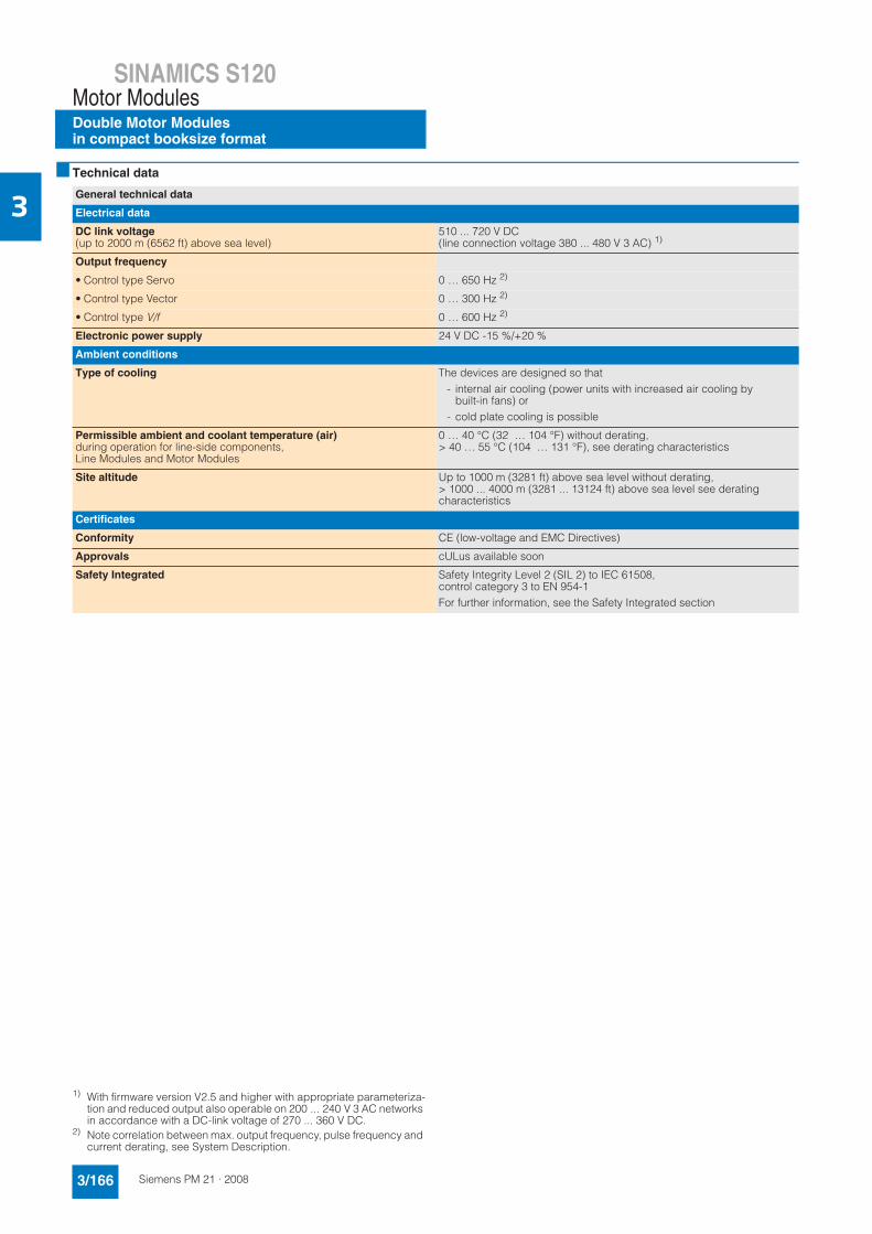
3■ Technical data
1) With firmware version V2.5 and higher with appropriate parameteriza-tion and reduced output also operable on 200 ... 240 V 3 AC networks in accordance with a DC-link voltage of 270 ... 360 V DC.
2) Note correlation between max. output frequency, pulse frequency and current derating, see System Description.
General technical data
Electrical data
DC link voltage(up to 2000 m (6562 ft) above sea level)
510 ... 720 V DC(line connection voltage 380 ... 480 V 3 AC) 1)
Output frequency
• Control type Servo 0 … 650 Hz 2)
• Control type Vector 0 … 300 Hz 2)
• Control type V/f 0 … 600 Hz 2)
Electronic power supply 24 V DC -15 %/+20 %
Ambient conditions
Type of cooling The devices are designed so that- internal air cooling (power units with increased air cooling by
built-in fans) or- cold plate cooling is possible
Permissible ambient and coolant temperature (air)during operation for line-side components, Line Modules and Motor Modules
0 … 40 °C (32 … 104 °F) without derating,> 40 … 55 °C (104 … 131 °F), see derating characteristics
Site altitude Up to 1000 m (3281 ft) above sea level without derating,> 1000 ... 4000 m (3281 ... 13124 ft) above sea level see derating characteristics
Certificates
Conformity CE (low-voltage and EMC Directives)
Approvals cULus available soon
Safety Integrated Safety Integrity Level 2 (SIL 2) to IEC 61508,control category 3 to EN 954-1For further information, see the Safety Integrated section
SINAMICS S120Motor Modules
Double Motor Modulesin compact booksize format
3/167Siemens PM 21 · 2008
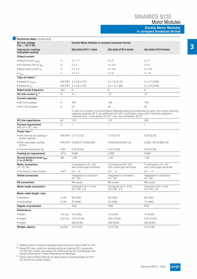
3■ Technical data (continued)
1) Rated power of a typical standard asynchronous motor at 400 V 3 AC.2) Rated DC link current for dimensioning an external DC connection.
For DC link current calculation for dimensioning the Line Module, see System Description "Power Modules/Line Modules".
3) Power loss of Motor Module at rated power including losses of 24 V DC electronic power supply.
DC link voltage 510 ... 720 V DC
Double Motor Module in compact booksize format
Internal air cooling/cold plate cooling
6SL3420-2TE11-7AA0 6SL3420-2TE13-0AA0 6SL3420-2TE15-0AA0
Output current
• Rated current Irated A 2 × 1.7 2 × 3 2 × 5
• for S6 duty (40 %) IS6 A 2 × 2 2 × 3.5 2 × 6
• Base-load current IH A 2 × 1.5 2 × 2.6 2 × 4.3
• Imax A 2 × 5.1 2 × 9 2 × 15
Type of output 1)
• based on Irated kW (HP) 2 × 0.9 (1.21) 2 × 1.6 (2.15) 2 × 2.7 (3.62)
• based on IH kW (HP) 2 × 0.8 (1.07) 2 × 1.4 (1.88) 2 × 2.3 (3.08)
Rated pulse frequency kHz 8 8 8
DC link current Id2) A 4.1 7.2 12
Current capacity
• DC link busbars A 100 100 100
• 24 V DC busbars A 20 20 20
If, due to a number of Line and Motor Modules being mounted side-by-side, the current carrying capacity exceeds 20 A, an additional 24-V-DC connection using a 24-V terminal adapter is required (max. cross section 6 mm2, max. fuse protection 20 A).
DC link capacitance μF 110 110 220
Current requirementwith 24 V DC, max.
A 1 1 1
Power loss 3)
• with internal air cooling in control cabinet
kW (HP) 0.11 (0.15) 0.13 (0.17) 0.19 (0.25)
• With cold plate cooling, int./ext.
kW (HP) 0.04/0.07 (0.05/0.09) 0.04/0.09 (0.05/0.12) 0.06/0.135 (0.08/0.18)
• Thermal resistance Rth K/W 0.22 (0.30) 0.22 (0.30) 0.22 (0.30)
Cooling air requirement m3/s 0.008 0.008 0.008
Sound pressure level LpA(1 m (3.28 ft))
dB < 60 < 60 < 60
Motor connectionU2, V2, W2
2 connectors (X1, X2) with screw-type terminals
2 connectors (X1, X2) with screw-type terminals
2 connectors (X1, X2) with screw-type terminals
• Conductor cross-section mm2 0.2 … 6 0.2 … 6 0.2 … 6
Shield connection integrated in connector (X1, X2)
integrated in connector (X1, X2)
integrated in connector (X1, X2)
PE connection M5 screw M5 screw M5 screw
Motor brake connection Connector (X11, X12), 24 V DC, 2 A
Connector (X11, X12), 24 V DC, 2 A
Connector (X11, X12), 24 V DC, 2 A
Motor cable length, max.
• Shielded m (ft) 50 (164) 50 (164) 50 (164)
• Unshielded m (ft) 75 (246) 75 (246) 75 (246)
Degree of protection IP20 IP20 IP20
Dimensions
• Width mm (in) 75 (2.95) 75 (2.95) 75 (2.95)
• Height mm (in) 270 (10.63) 270 (10.63) 270 (10.63)
• Depth 226 (8.90) 226 (8.90) 226 (8.90)
Weight, approx. kg (lb) 3.4 (7.50) 3.4 (7.50) 3.4 (7.50)
SINAMICS S120Motor ModulesDouble Motor Modulesin compact booksize format
3/168 Siemens PM 21 · 2008
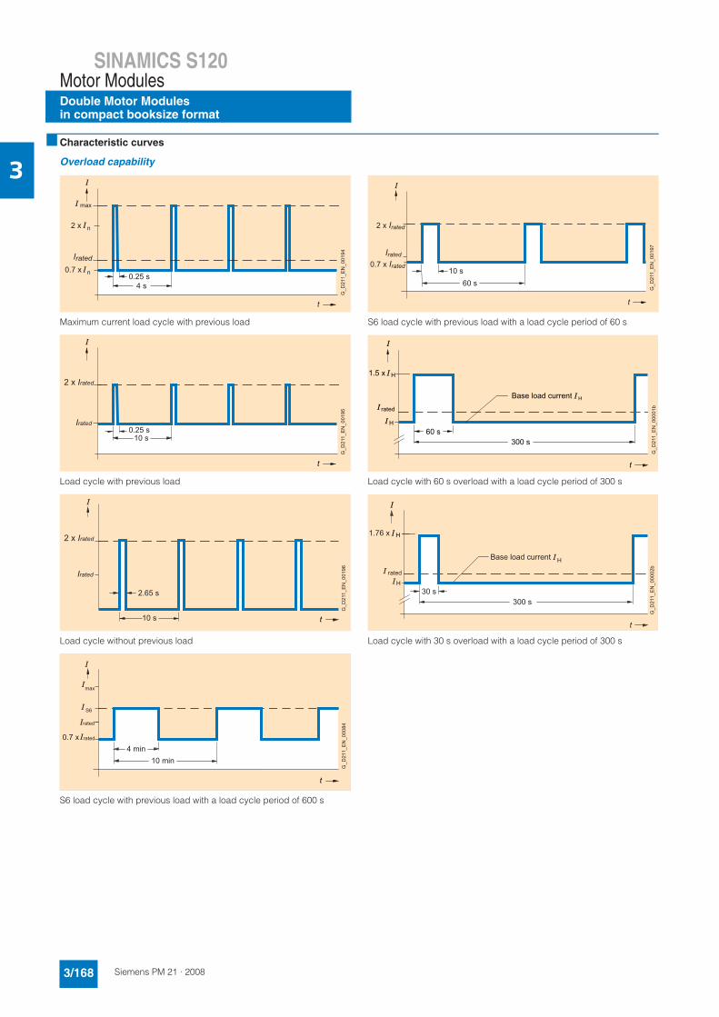
3■ Characteristic curves
Overload capability
Maximum current load cycle with previous load
Load cycle with previous load
Load cycle without previous load
S6 load cycle with previous load with a load cycle period of 600 s
S6 load cycle with previous load with a load cycle period of 60 s
Load cycle with 60 s overload with a load cycle period of 300 s
Load cycle with 30 s overload with a load cycle period of 300 s
max
4 s
t
Irated
0.25 s
G_D
211_
EN
_001
94
n
n0.7 x
2 x
10 s
t
Irated0.25 s
G_D
211_
EN
_001
95
2 x Irated
10 s t
G_D
211_
EN
_001
96Irated
2.65 s
2 x Irated
G_D211_EN_00084
4 min
max
S6
10 min
t
0.7 x rated
rated
G_D
211_
EN
_000
84
10 s60 s
t
2 x Irated
G_D
211_
EN
_001
97
0.7 x IratedIrated
60 s 300 s
t
H
H
1.5 x
Base load current H
rated
G_D
211_
EN
_000
01b
30 s300 s
t
H
H1.76 x
Base load current
rated
H
G_D
211_
EN
_000
02b
SINAMICS S120Motor Modules
Double Motor Modulesin compact booksize format
3/169Siemens PM 21 · 2008
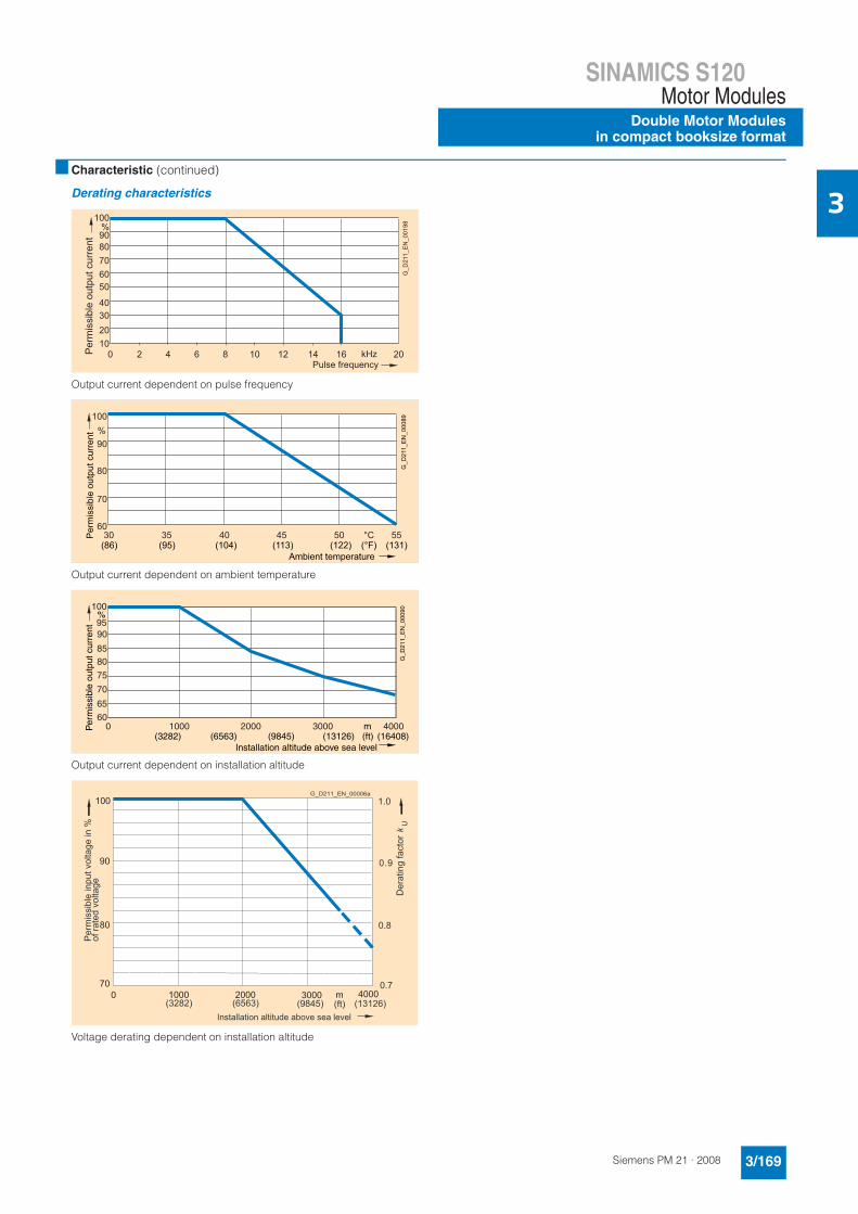
3■ Characteristic (continued)
Derating characteristics
Output current dependent on pulse frequency
Output current dependent on ambient temperature
Output current dependent on installation altitude
Voltage derating dependent on installation altitude
100
90 80 70 60 50
0 4 8 12 16 20
40 30 20 10
2 6 10 14
%
kHz Per
mis
sibl
e ou
tput
cur
rent
Pulse frequency
G_D
211_
EN
_001
98
Per
mis
sibl
e ou
tput
cur
rent
Ambient temperature
G_D
211_
EN
_000
89
(86) (95) (104) (113) (122) (131)(°F)
100
90
80
70
6030 35 40 45 50 55
%
°C
100
9590
8580
75
0 1000 2000 3000 4000
70
65
60
Per
mis
sibl
e ou
tput
cur
rent
Installation altitude above sea level
%
m
G_D
211_
EN
_000
90
(ft)(3282) (6563) (9845) (13126) (16408)
Per
mis
sibl
e in
put v
olta
ge in
%of
rate
d vo
ltage
G_D211_EN_00006a
(3282) (6563) (9845) (ft) (13126)
1.0
0.9
0.7
0.8
Installation altitude above sea level
Der
atin
g fa
ctor
kU
1000 2000 m0 3000 4000
100
90
80
70