ST-066B-01 REV0 Idrante soprasuolo EUR A 2vie DN80 100 P500 · Idrante soprasuolo modello EUR tipo...
8
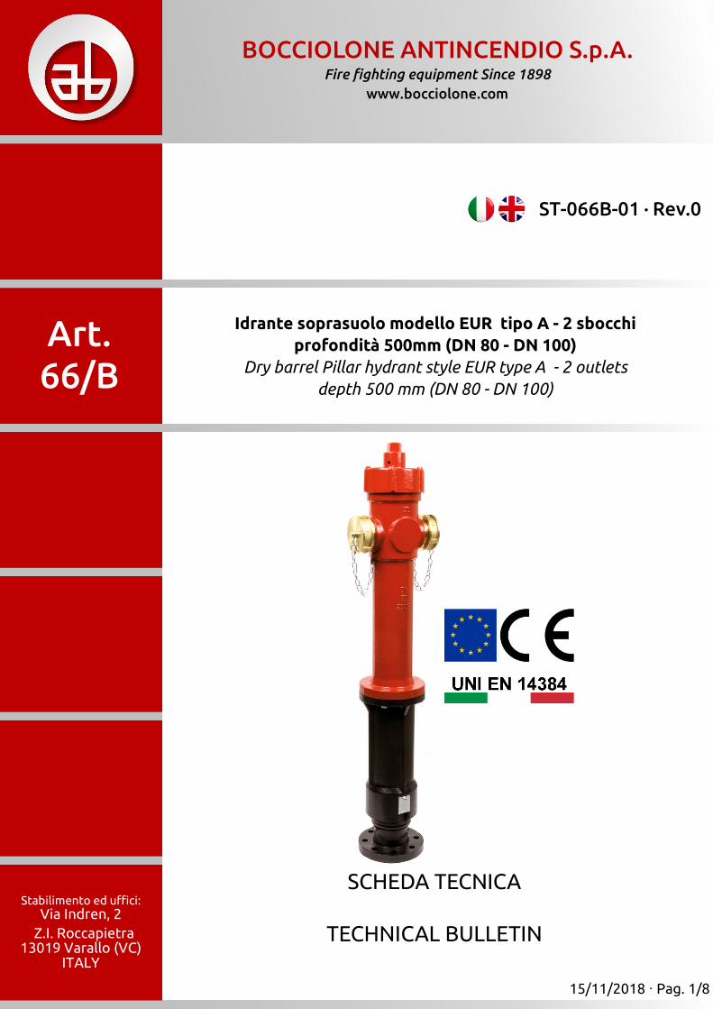
BOCCIOLONE ANTINCENDIO S.p.A. Fire ghting equipment Since 1898 www.bocciolone.com Stabilimento ed uci: Via Indren, 2 Z.I. Roccapietra 13019 Varallo (VC) ITALY 15/11/2018 · Pag. 1/8 Art. 66/B ST-066B-01 · Rev.0 Idrante soprasuolo modello EUR tipo A - 2 sbocchi profondità 500mm (DN 80 - DN 100) Dry barrel Pillar hydrant style EUR type A - 2 outlets depth 500 mm (DN 80 - DN 100) SCHEDA TECNICA TECHNICAL BULLETIN UNI EN 14384
Transcript of ST-066B-01 REV0 Idrante soprasuolo EUR A 2vie DN80 100 P500 · Idrante soprasuolo modello EUR tipo...
BOCCIOLONE ANTINCENDIO S.p.A. Fire �ghting equipment Since 1898
www.bocciolone.com
Stabilimento ed u�ci: Via Indren, 2
Z.I. Roccapietra 13019 Varallo (VC)
ITALY
15/11/2018 · Pag. 1/8
Art. 66/B
ST-066B-01 · Rev.0
Idrante soprasuolo modello EUR tipo A - 2 sbocchi
profondità 500mm (DN 80 - DN 100)
Dry barrel Pillar hydrant style EUR type A - 2 outlets
depth 500 mm (DN 80 - DN 100)
SCHEDA TECNICA
TECHNICAL BULLETIN
UNI EN 14384

Idrante soprasuolo modello EUR tipo A 2 sbocchi profondità 500 (DN 80 - DN 100) Dry barrel Pillar hydrant style EUR type A 2 outlets depth 500 (DN 80 - DN 100)
15/11/2018 ST-066B-01 Rev.0 · Pag. 2/8
www.bocciolone.com
Art.66/B
INDICE
INDEX
1. DESCRIZIONE GENERALE
GENERAL DESCRIPTION Pag. 3
2. CARATTERISTICHE TECNICHE
TECHNICAL FEATURES Pag. 3
3. DIMENSIONI E PESO
DIMENSIONS AND WEIGHT Pag. 4
4. COMPONENTI
COMPONENTS Pag. 5
5. MATERIALI
MATERIALS Pag. 5
6. RICAMBI
SPARE PARTS Pag. 6
7. DATI IDRAULICI
HYDRAULIC DATA Pag. 7
8. NOTA IMPORTANTE SULLA TENUTA DELL’IDRANTE
IMPORTANT NOTE ABOUT HYDRANT TIGHTNESS Pag. 8
Idrante soprasuolo modello EUR tipo A 2 sbocchi profondità 500 (DN 80 - DN 100) Dry barrel Pillar hydrant style EUR type A 2 outlets depth 500 (DN 80 - DN 100)
15/11/2018 ST-066B-01 Rev.0 · Pag. 3/8
www.bocciolone.com
Art.66/B
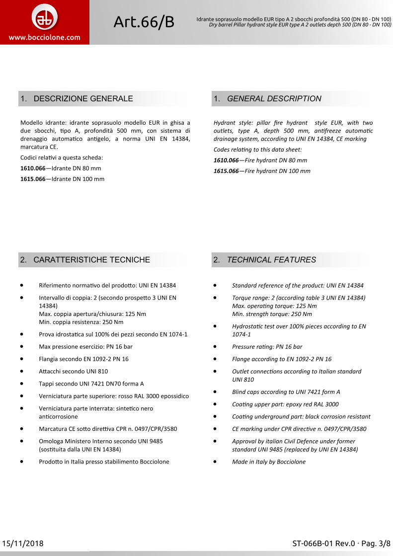
Modello idrante: idrante soprasuolo modello EUR in ghisa a
due sbocchi, 1po A, profondità 500 mm, con sistema di
drenaggio automa1co an1gelo, a norma UNI EN 14384,
marcatura CE.
Codici rela1vi a questa scheda:
1610.066—Idrante DN 80 mm
1615.066—Idrante DN 100 mm
1. DESCRIZIONE GENERALE
Hydrant style: pillar fire hydrant style EUR, with two
outlets, type A, depth 500 mm, an+freeze automa+c
drainage system, according to UNI EN 14384, CE marking
Codes rela+ng to this data sheet:
1610.066—Fire hydrant DN 80 mm
1615.066—Fire hydrant DN 100 mm
1. GENERAL DESCRIPTION
Riferimento norma1vo del prodo8o: UNI EN 14384
Intervallo di coppia: 2 (secondo prospe8o 3 UNI EN
14384)
Max. coppia apertura/chiusura: 125 Nm
Min. coppia resistenza: 250 Nm
Prova idrosta1ca sul 100% dei pezzi secondo EN 1074-1
Max pressione esercizio: PN 16 bar
Flangia secondo EN 1092-2 PN 16
A8acchi secondo UNI 810
Tappi secondo UNI 7421 DN70 forma A
Verniciatura parte superiore: rosso RAL 3000 epossidico
Verniciatura parte interrata: sinte1co nero
an1corrosione
Marcatura CE so8o direCva CPR n. 0497/CPR/3580
Omologa Ministero Interno secondo UNI 9485
(sos1tuita dalla UNI EN 14384)
Prodo8o in Italia presso stabilimento Bocciolone
2. CARATTERISTICHE TECNICHE
Standard reference of the product: UNI EN 14384
Torque range: 2 (according table 3 UNI EN 14384)
Max. opera+ng torque: 125 Nm
Min. strength torque: 250 Nm
Hydrosta+c test over 100% pieces according to EN
1074-1
Pressure ra+ng: PN 16 bar
Flange according to EN 1092-2 PN 16
Outlet connec+ons according to Italian standard
UNI 810
Blind caps according to UNI 7421 form A
Coa+ng upper part: epoxy red RAL 3000
Coa+ng underground part: black corrosion resistant
CE marking under CPR direc+ve n. 0497/CPR/3580
Approval by italian Civil Defence under former
standard UNI 9485 (replaced by UNI EN 14384)
Made in Italy by Bocciolone
2. TECHNICAL FEATURES

Idrante soprasuolo modello EUR tipo A 2 sbocchi profondità 500 (DN 80 - DN 100) Dry barrel Pillar hydrant style EUR type A 2 outlets depth 500 (DN 80 - DN 100)
15/11/2018 ST-066B-01 Rev.0 · Pag. 4/8
www.bocciolone.com
Art.66/B
3. DIMENSIONI E PESO - DIMENSIONS AND WEIGHT
Fig. 1
Nota: le dimensioni possono variare senza preavviso
Remark: dimensions might change without prior advice
DN 80 1610.066
IDRANTE - HYDRANT
H 1200mm
A 450mm
P 500mm
D 180mm
L 265mm
FLANGIA - FLANGE
DN 80mm
a 19mm
b 160mm
c 200mm
PESO - WEIGHT
Numero di giri per
apertura completa
dell'idrante
Number of turns to fully
open the hydrant
G 8
54 kg
DN 100 1615.066
IDRANTE - HYDRANT
H 1220mm
A 450mm
P 500mm
D 200mm
L 280mm
FLANGIA - FLANGE
DN 100mm
a 19mm
b 180mm
c 220mm
PESO - WEIGHT
Numero di giri per
apertura completa
dell'idrante
Number of turns to fully
open the hydrant
G 7
63 kg
TOLLERANZE GENERALI
GENERAL TOLERANCES
Dimensioni
Dimensions ±5mm
Peso
Weight ±5%
Vista dall’alto
Top view
Vista frontale
Front view
Flangia
Flange
Idrante soprasuolo modello EUR tipo A 2 sbocchi profondità 500 (DN 80 - DN 100) Dry barrel Pillar hydrant style EUR type A 2 outlets depth 500 (DN 80 - DN 100)
15/11/2018 ST-066B-01 Rev.0 · Pag. 5/8
www.bocciolone.com
Art.66/B
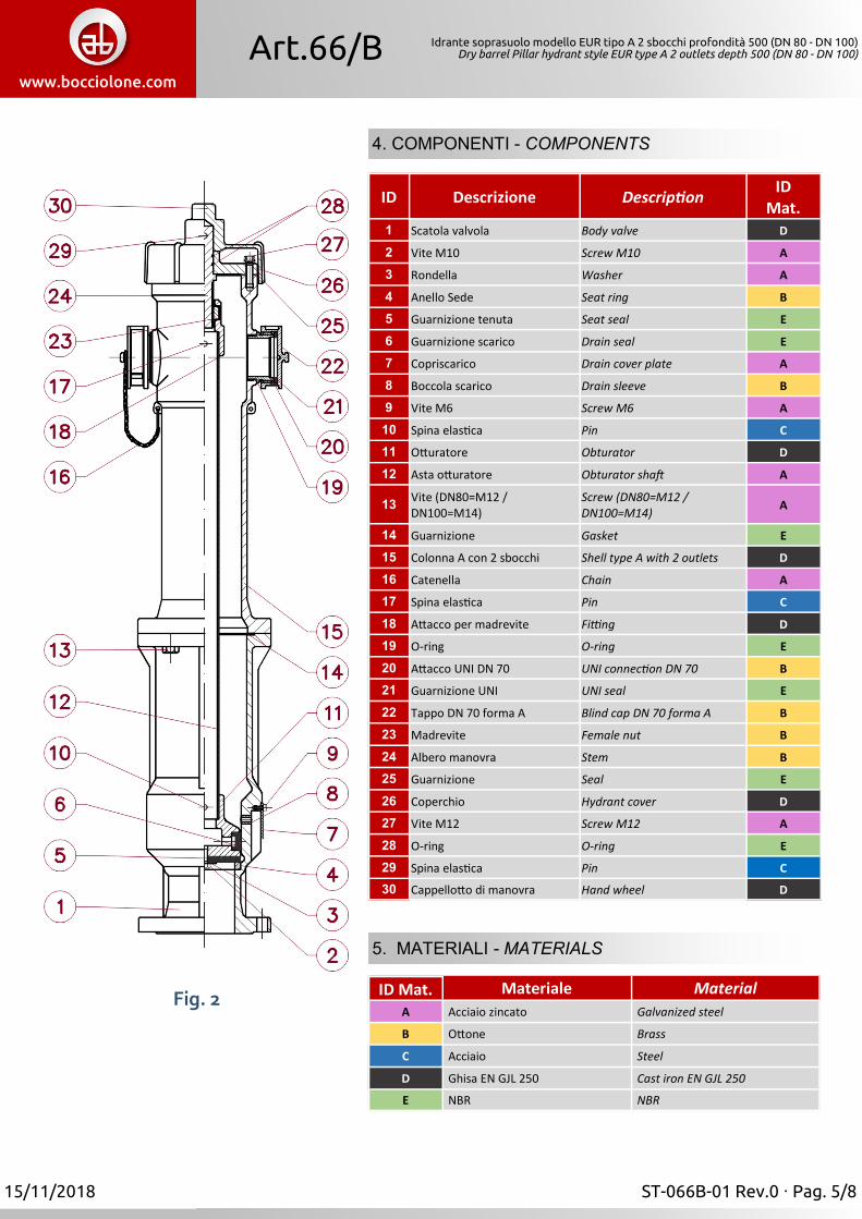
ID Mat. Materiale Material
A Acciaio zincato Galvanized steel
B O8one Brass
C Acciaio Steel
D Ghisa EN GJL 250 Cast iron EN GJL 250
E NBR NBR
5. MATERIALI - MATERIALS
4. COMPONENTI - COMPONENTS
Fig. 2
ID Descrizione Descrip+on ID
Mat.
1 Scatola valvola Body valve D
2 Vite M10 Screw M10 A
3 Rondella Washer A
4 Anello Sede Seat ring B
5 Guarnizione tenuta Seat seal E
6 Guarnizione scarico Drain seal E
7 Copriscarico Drain cover plate A
8 Boccola scarico Drain sleeve B
9 Vite M6 Screw M6 A
10 Spina elas1ca Pin C
11 O8uratore Obturator D
12 Asta o8uratore Obturator shaE A
13 Vite (DN80=M12 /
DN100=M14)
Screw (DN80=M12 /
DN100=M14) A
14 Guarnizione Gasket E
15 Colonna A con 2 sbocchi Shell type A with 2 outlets D
16 Catenella Chain A
17 Spina elas1ca Pin C
18 A8acco per madrevite FiGng D
19 O-ring O-ring E
20 A8acco UNI DN 70 UNI connec+on DN 70 B
21 Guarnizione UNI UNI seal E
22 Tappo DN 70 forma A Blind cap DN 70 forma A B
23 Madrevite Female nut B
24 Albero manovra Stem B
25 Guarnizione Seal E
26 Coperchio Hydrant cover D
27 Vite M12 Screw M12 A
28 O-ring O-ring E
29 Spina elas1ca Pin C
30 Cappello8o di manovra Hand wheel D
Idrante soprasuolo modello EUR tipo A 2 sbocchi profondità 500 (DN 80 - DN 100) Dry barrel Pillar hydrant style EUR type A 2 outlets depth 500 (DN 80 - DN 100)
15/11/2018 ST-066B-01 Rev.0 · Pag. 6/8
www.bocciolone.com
Art.66/B
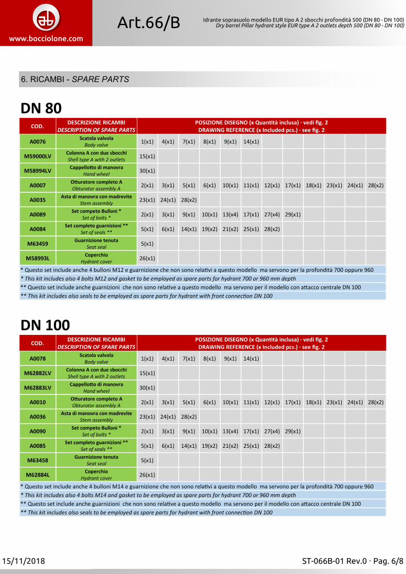
6. RICAMBI - SPARE PARTS
DN 80 COD.
DESCRIZIONE RICAMBI
DESCRIPTION OF SPARE PARTS
POSIZIONE DISEGNO (x Quan6tà inclusa) · vedi fig. 2
DRAWING REFERENCE (x Included pcs.) · see fig. 2
A0076 Scatola valvola
Body valve 1(x1) 4(x1) 7(x1) 8(x1) 9(x1) 14(x1)
M59000LV Colonna A con due sbocchi
Shell type A with 2 outlets 15(x1)
M58994LV Cappello?o di manovra
Hand wheel 30(x1)
A0007 O?uratore completo A
Obturator assembly A 2(x1) 3(x1) 5(x1) 6(x1) 10(x1) 11(x1) 12(x1) 17(x1) 18(x1) 23(x1) 24(x1) 28(x2)
A0035 Asta di manovra con madrevite
Stem assembly 23(x1) 24(x1) 28(x2)
A0089 Set competo Bulloni *
Set of bolts * 2(x1) 3(x1) 9(x1) 10(x1) 13(x4) 17(x1) 27(x4) 29(x1)
A0084 Set completo guarnizioni **
Set of seals ** 5(x1) 6(x1) 14(x1) 19(x2) 21(x2) 25(x1) 28(x2)
M63459 Guarnizione tenuta
Seat seal 5(x1)
M58993L Coperchio
Hydrant cover 26(x1)
* Questo set include anche 4 bulloni M12 e guarnizione che non sono rela1vi a questo modello ma servono per la profondità 700 oppure 960
* This kit includes also 4 bolts M12 and gasket to be employed as spare parts for hydrant 700 or 960 mm depth
** Questo set include anche guarnizioni che non sono rela1ve a questo modello ma servono per il modello con a8acco centrale DN 100
** This kit includes also seals to be employed as spare parts for hydrant with front connec+on DN 100
DN 100 COD.
DESCRIZIONE RICAMBI
DESCRIPTION OF SPARE PARTS
POSIZIONE DISEGNO (x Quan6tà inclusa) · vedi fig. 2
DRAWING REFERENCE (x Included pcs.) · see fig. 2
A0078 Scatola valvola
Body valve 1(x1) 4(x1) 7(x1) 8(x1) 9(x1) 14(x1)
M62882LV Colonna A con due sbocchi
Shell type A with 2 outlets 15(x1)
M62883LV Cappello?o di manovra
Hand wheel 30(x1)
A0010 O?uratore completo A
Obturator assembly A 2(x1) 3(x1) 5(x1) 6(x1) 10(x1) 11(x1) 12(x1) 17(x1) 18(x1) 23(x1) 24(x1) 28(x2)
A0036 Asta di manovra con madrevite
Stem assembly 23(x1) 24(x1) 28(x2)
A0090 Set competo Bulloni *
Set of bolts * 2(x1) 3(x1) 9(x1) 10(x1) 13(x4) 17(x1) 27(x4) 29(x1)
A0085 Set completo guarnizioni **
Set of seals ** 5(x1) 6(x1) 14(x1) 19(x2) 21(x2) 25(x1) 28(x2)
M63458 Guarnizione tenuta
Seat seal 5(x1)
M62884L Coperchio
Hydrant cover 26(x1)
* Questo set include anche 4 bulloni M14 e guarnizione che non sono rela1vi a questo modello ma servono per la profondità 700 oppure 960
* This kit includes also 4 bolts M14 and gasket to be employed as spare parts for hydrant 700 or 960 mm depth
** Questo set include anche guarnizioni che non sono rela1ve a questo modello ma servono per il modello con a8acco centrale DN 100
** This kit includes also seals to be employed as spare parts for hydrant with front connec+on DN 100

Idrante soprasuolo modello EUR tipo A 2 sbocchi profondità 500 (DN 80 - DN 100) Dry barrel Pillar hydrant style EUR type A 2 outlets depth 500 (DN 80 - DN 100)
15/11/2018 ST-066B-01 Rev.0 · Pag. 7/8
www.bocciolone.com
Art.66/B
5. DATI IDRAULICI - HYDRAULIC DATA 7. DATI IDRAULICI - HYDRAULIC DATA
A?enzione: il dato è rilevato con l’idrante in posizione orizzontale. Ai fini del calcolo va aggiunta la perdita di carico dovuta alla
differenza di quota geometrica.
Remark: the pressure drop has been obtained with hydrant in horizontal posi+on. To calculate the correct value of the pressure
drop the figure shall be increased with pressure drop due to height difference between inlet and outlet.
GRAFICO PERDITA DI CARICO CON UNA BOCCA IN FUNZIONE
PRESSURE DROP WITH ONE OUTLET WORKING
GRAFICO PERDITA DI CARICO CON DUE BOCCHE IN FUNZIONE
PRESSURE DROP WITH TWO OUTLET WORKING
Fig. 4
Fig. 3
Idrante soprasuolo modello EUR tipo A 2 sbocchi profondità 500 (DN 80 - DN 100) Dry barrel Pillar hydrant style EUR type A 2 outlets depth 500 (DN 80 - DN 100)
15/11/2018 ST-066B-01 Rev.0 · Pag. 8/8
www.bocciolone.com
Art.66/B
Bocciolone Antincendio S.p.A.—Via Indren, 2 Z.I. Roccapietra 13019 Varallo (VC) - ITALY Tel.: 0163-568811 Fax: 0163-322022 - [email protected]
Bocciolone Antincendio S.p.A. si riserva il diritto, continuando lo sviluppo del prodotto, di modificare design, materiali e specifiche senza preavviso
Bocciolone Antincendio S.p.A. reserves the right to change the design, materials and specifications without notice to continue product development
Tutti i diritti riservati—All rights reserved
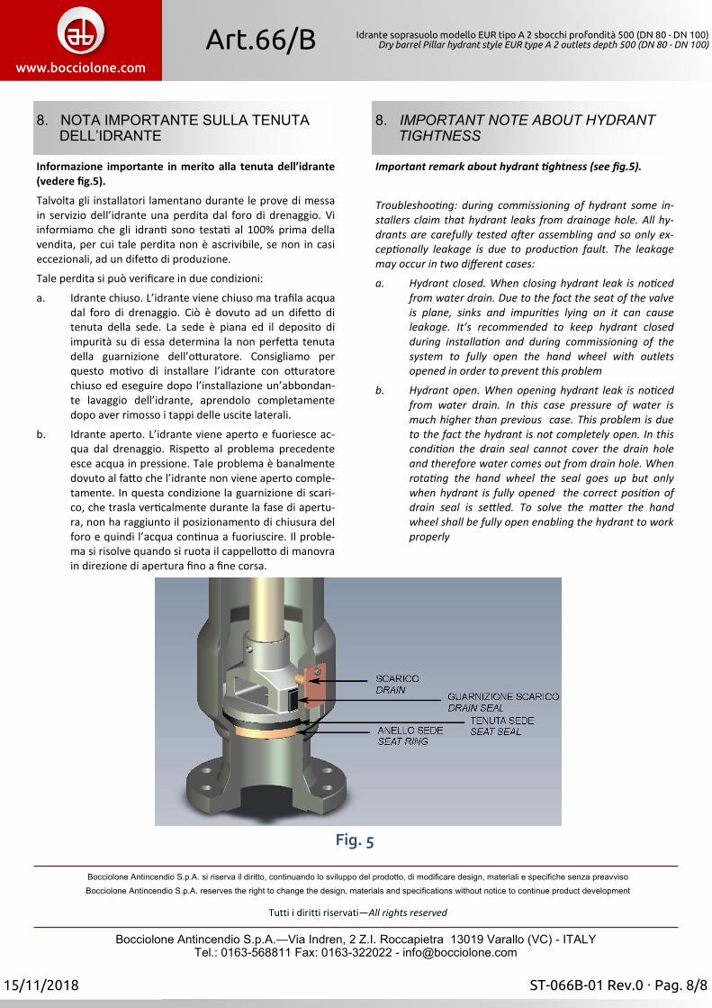
8. NOTA IMPORTANTE SULLA TENUTA DELL’IDRANTE
8. IMPORTANT NOTE ABOUT HYDRANT TIGHTNESS
Informazione importante in merito alla tenuta dell’idrante
(vedere fig.5).
Talvolta gli installatori lamentano durante le prove di messa
in servizio dell’idrante una perdita dal foro di drenaggio. Vi
informiamo che gli idran1 sono testa1 al 100% prima della
vendita, per cui tale perdita non è ascrivibile, se non in casi
eccezionali, ad un dife8o di produzione.
Tale perdita si può verificare in due condizioni:
a. Idrante chiuso. L’idrante viene chiuso ma trafila acqua
dal foro di drenaggio. Ciò è dovuto ad un dife8o di
tenuta della sede. La sede è piana ed il deposito di
impurità su di essa determina la non perfe8a tenuta
della guarnizione dell’o8uratore. Consigliamo per
questo mo1vo di installare l’idrante con o8uratore
chiuso ed eseguire dopo l’installazione un’abbondan-
te lavaggio dell’idrante, aprendolo completamente
dopo aver rimosso i tappi delle uscite laterali.
b. Idrante aperto. L’idrante viene aperto e fuoriesce ac-
qua dal drenaggio. Rispe8o al problema precedente
esce acqua in pressione. Tale problema è banalmente
dovuto al fa8o che l’idrante non viene aperto comple-
tamente. In questa condizione la guarnizione di scari-
co, che trasla ver1calmente durante la fase di apertu-
ra, non ha raggiunto il posizionamento di chiusura del
foro e quindi l’acqua con1nua a fuoriuscire. Il proble-
ma si risolve quando si ruota il cappello8o di manovra
in direzione di apertura fino a fine corsa.
Important remark about hydrant +ghtness (see fig.5).
Troubleshoo+ng: during commissioning of hydrant some in-
stallers claim that hydrant leaks from drainage hole. All hy-
drants are carefully tested aEer assembling and so only ex-
cep+onally leakage is due to produc+on fault. The leakage
may occur in two different cases:
a. Hydrant closed. When closing hydrant leak is no+ced
from water drain. Due to the fact the seat of the valve
is plane, sinks and impuri+es lying on it can cause
leakage. It’s recommended to keep hydrant closed
during installa+on and during commissioning of the
system to fully open the hand wheel with outlets
opened in order to prevent this problem
b. Hydrant open. When opening hydrant leak is no+ced
from water drain. In this case pressure of water is
much higher than previous case. This problem is due
to the fact the hydrant is not completely open. In this
condi+on the drain seal cannot cover the drain hole
and therefore water comes out from drain hole. When
rota+ng the hand wheel the seal goes up but only
when hydrant is fully opened the correct posi+on of
drain seal is seKled. To solve the maKer the hand
wheel shall be fully open enabling the hydrant to work
properly
Fig. 5