REGOLATORE AUTOMATICO DEL FATTORE DI POTENZA … · REGOLATORE AUTOMATICO DEL FATTORE DI POTENZA...
40
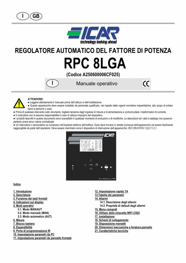
REGOLATORE AUTOMATICO DEL FATTORE DI POTENZA RPC 8LGA (Codice A250600006CF025) ATTENZIONE! ● Leggere attentamente il manuale prima dell’utilizzo e dell’installazione. ● Questo apparecchio deve essere installato da personale qualificato, nel rispetto delle vigenti normative impiantistiche, allo scopo di evitare danni a persone o cose. ● Prima di qualsiasi intervento sullo strumento, togliere tensione dagli ingressi di misura e di alimentazione e cortocircuitare i trasformatori di corrente. ● Il costruttore non si assume responsabilità in caso di utilizzo improprio del dispositivo. ● I prodotti descritti in questo documento sono suscettibili in qualsiasi momento di evoluzioni o di modifiche. Le descrizioni ed i dati a catalogo non possono pertanto avere alcun valore contrattuale. ● Un interruttore o sezionatore va compreso nell’impianto elettrico dell’edificio. Esso deve trovarsi in stretta vicinanza dell’apparecchio ed essere facilmente raggiungibile da parte dell’operatore. Deve essere marchiato come il dispositivo di interruzione dell’apparecchio: IEC/ EN 61010-1 § 6.11.2.1. Indice 1. Introduzione 2. Descrizione 3. Funzione dei tasti frontali 4. Indicazioni sul display 5. Modi operativi 5.1. Modo MAN/AUT 5.2. Modo manuale (MAN) 5.3. Modo automatico (AUT) 6. Misure 7. Blocco tastiera 8. Espandibilità 9. Porta di programmazione IR 10. Impostazione parametri da PC 11. Impostazione parametri da pannello frontale 12. Impostazione rapida TA 13.Tabella dei parametri 14. Allarmi 14.1. Descrizione degli allarmi 14.2. Proprietà di default degli allarmi 15. Menu comandi 16. Utilizzo della chiavetta WIFI CX02 17. Installazione 18. Schemi di collegamento 19. Disposizione morsetti 20. Dimensioni meccaniche e foratura pannello 21. Caratteristiche tecniche I GB I Manuale operativo
Transcript of REGOLATORE AUTOMATICO DEL FATTORE DI POTENZA … · REGOLATORE AUTOMATICO DEL FATTORE DI POTENZA...
REGOLATORE AUTOMATICO DEL FATTORE DI POTENZA
RPC 8LGA (Codice A250600006CF025)
ATTENZIONE! ● Leggere attentamente il manuale prima dell’utilizzo e dell’installazione. ● Questo apparecchio deve essere installato da personale qualificato, nel rispetto delle vigenti normative impiantistiche, allo scopo di evitare danni a persone o cose.
● Prima di qualsiasi intervento sullo strumento, togliere tensione dagli ingressi di misura e di alimentazione e cortocircuitare i trasformatori di corrente. ● Il costruttore non si assume responsabilità in caso di utilizzo improprio del dispositivo. ● I prodotti descritti in questo documento sono suscettibili in qualsiasi momento di evoluzioni o di modifiche. Le descrizioni ed i dati a catalogo non possono pertanto avere alcun valore contrattuale. ● Un interruttore o sezionatore va compreso nell’impianto elettrico dell’edificio. Esso deve trovarsi in stretta vicinanza dell’apparecchio ed essere facilmente raggiungibile da parte dell’operatore. Deve essere marchiato come il dispositivo di interruzione dell’apparecchio: IEC/ EN 61010-1 § 6.11.2.1.
Indice 1. Introduzione 2. Descrizione 3. Funzione dei tasti frontali 4. Indicazioni sul display 5. Modi operativi
5.1. Modo MAN/AUT 5.2. Modo manuale (MAN) 5.3. Modo automatico (AUT)
6. Misure 7. Blocco tastiera 8. Espandibilità 9. Porta di programmazione IR 10. Impostazione parametri da PC 11. Impostazione parametri da pannello frontale
12. Impostazione rapida TA 13.Tabella dei parametri 14. Allarmi
14.1. Descrizione degli allarmi 14.2. Proprietà di default degli allarmi
15. Menu comandi 16. Utilizzo della chiavetta WIFI CX02 17. Installazione 18. Schemi di collegamento 19. Disposizione morsetti 20. Dimensioni meccaniche e foratura pannello 21. Caratteristiche tecniche
I GB
I Manuale operativo
p. 2 / 40
1. Introduzione Il regolatore RPC 8LGA è stato progettato incorporando lo stato dell’arte delle funzioni richieste per le applicazioni di rifasamento. Realizzato con un contenitore dedicato, di dimensioni estremamente compatte, il regolatore RPC 8LGA unisce il moderno design del frontale alla praticità di montaggio e alla possibilità di espansione sul retro, dove è possibile alloggiare un modulo di espansione con funzioni aggiuntive. Il display grafico LCD consente una interfaccia utente chiara ed intuitiva. 2. Descrizione Controllore automatico del fattore di potenza. Montaggio a pannello, contenitore standard 144x144mm. Display LCD a icone retroilluminato. Versioni:
o 8LGA con 8 gradini, espandibile a 14 max. 5 tasti di navigazione per funzioni ed impostazioni. Messaggi di allarme con testi in 6 lingue. Bus di espansione con 2 slot per moduli di espansione: o Interfacce di comunicazione RS232, RS485, USB, Ethernet. o Uscite a relè aggiuntive
Elevata accuratezza delle misure in vero valore efficace (TRMS). Vasta gamma di misure disponibili, inclusive di THD di tensione e di corrente con analisi delle singole armoniche fino al
15.mo ordine. Ingresso di misura tensione separato dall’alimentazione, utilizzabile con TV in applicazioni di media tensione. Alimentazione ausiliaria ad ampio intervallo di tensione (100-440 VAC). Interfaccia di programmazione ottica frontale, isolata galvanicamente, alta velocità, impermeabile, compatibile con chiavetta
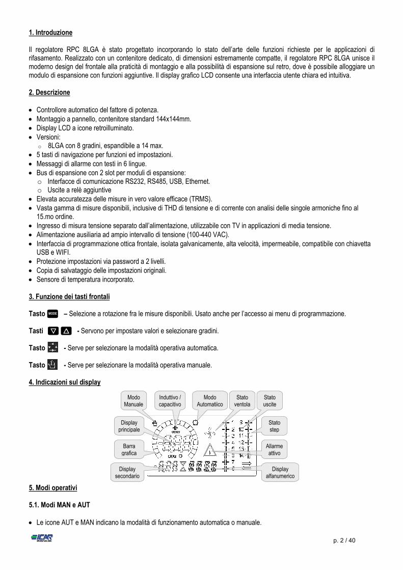
USB e WIFI. Protezione impostazioni via password a 2 livelli. Copia di salvataggio delle impostazioni originali. Sensore di temperatura incorporato. 3. Funzione dei tasti frontali Tasto – Selezione a rotazione fra le misure disponibili. Usato anche per l’accesso ai menu di programmazione. Tasti - Servono per impostare valori e selezionare gradini. Tasto - Serve per selezionare la modalità operativa automatica. Tasto - Serve per selezionare la modalità operativa manuale. 4. Indicazioni sul display
5. Modi operativi 5.1. Modi MAN e AUT Le icone AUT e MAN indicano la modalità di funzionamento automatica o manuale.
MODE
▼ ▲
Stato uscite
Stato ventola
Display secondario
Allarme attivo
Modo Automatiico
Modo Manuale
Display principale
Induttivo / capacitivo
Barra grafica
Display alfanumerico
Stato step
p. 3 / 40
Per cambiare le modalità di funzionamento automatico/manuale tenere premuti i tasti o per 1 secondo. La modalità di funzionamento rimane memorizzata anche in assenza della tensione di alimentazione.
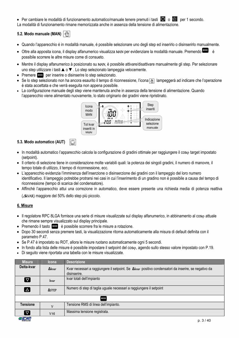
5.2. Modo manuale (MAN) Quando l’apparecchio é in modalità manuale, é possibile selezionare uno degli step ed inserirlo o disinserirlo manualmente.
Oltre alla apposita icona, il display alfanumerico visualizza MAN per evidenziare la modalità manuale. Premendo è possibile scorrere le altre misure come di consueto.
Mentre il display alfanumerico à posizionato su MAN, è possibile attivare/disattivare manualmente gli step. Per selezionare uno step utilizzare i tasti ▲o ▼. Lo step selezionato lampeggia velocemente.
Premere per inserire o disinserire lo step selezionato. Se lo step selezionato non ha ancora esaurito il tempo di riconnessione, l’icona lampeggerà ad indicare che l’operazione
è stata accettata e che verrà eseguita non appena possibile. La configurazione manuale degli step viene mantenuta anche in assenza della tensione di alimentazione. Quando
l’apparecchio viene alimentato nuovamente, lo stato originario dei gradini viene ripristinato.
5.3. Modo automatico (AUT) In modalità automatico l’apparecchio calcola la configurazione di gradini ottimale per raggiungere il cos target impostato
(setpoint). Il criterio di selezione tiene in considerazione molte variabili quali: la potenza dei singoli gradini, il numero di manovre, il
tempo totale di utilizzo, il tempo di riconnessione, ecc. L’apparecchio evidenzia l’imminenza dell’inserzione o disinserzione dei gradini con il lampeggio del loro numero
identificativo. Il lampeggio potrebbe protrarsi nei casi in cui l’inserimento di un gradino non è possibile a causa del tempo di riconnessione (tempo di scarica del condensatore).
Affinché l’apparecchio attui una correzione in automatico, deve essere presente una richiesta media di potenza reattiva
(kVAR) maggiore del 50% dello step più piccolo.
6. Misure Il regolatore RPC 8LGA fornisce una serie di misure visualizzate sul display alfanumerico, in abbinamento al cos attuale
che rimane sempre visualizzato sul display principale. Premendo il tasto è possibile scorrere fra le misure a rotazione. Dopo 30 secondi senza premere tasti, la visualizzazione ritorna automaticamente alla misura di default definita con il
parametro P.47. Se P.47 è impostato su ROT, allora le misure ruotano automaticamente ogni 5 secondi. In fondo alla lista delle misure è possibile impostare il setpoint del cos, agendo sullo stesso valore impostato con P.19. Di seguito viene riportata una tabella con le misure visualizzate.
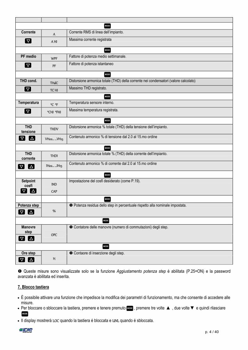
Misura Icona Descrizione Delta-kvar Δkvar Kvar necessari a raggiungere il setpoint. Se Δkvar positivo condensatori da inserire, se negativo da
disinserire.
kvar kvar totali dell’impianto
ΔSTEP Numero di step di taglia uguale necessari a raggiungere il setpoint
Tensione V Tensione RMS di linea dell’impianto.
V HI Massima tensione registrata.
MODE
▼
▲
▼
MODE
MODE
MODE
Indicazione selezione manuale
Step inseriti
Icona modo MAN
Tot kvar inseriti in
MAN
p. 4 / 40
Corrente A Corrente RMS di linea dell’impianto.
A HI Massima corrente registrata
PF medio WPF Fattore di potenza medio settimanale.
PF Fattore di potenza istantaneo
THD cond. THdC Distorsione armonica totale (THD) della corrente nei condensatori (valore calcolato)
TC HI Massimo THD registrato.
Temperatura °C °F Temperatura sensore interno.
°CHI °FHI Massima temperatura registrata.
THD
tensione THDV Distorsione armonica % totale (THD) della tensione dell’impianto.
VH02… …VH15 Contenuto armonico % di tensione dal 2.0 al 15.mo ordine
THD
corrente THDI Distorsione armonica totale % (THD) della corrente dell’impianto.
IH02… …IH15 Contenuto armonico % di corrente dal 2.0 al 15.mo ordine
Setpoint cosfi
IND
CAP
Impostazione del cosfi desiderato (come P.19).
Potenza step
%
Potenza residua dello step in percentuale rispetto alla nominale impostata.
Manovre step
OPC
Contatore delle manovre (numero di commutazioni) degli step.
Ore step
H
Contaore di inserzione degli step.
Queste misure sono visualizzate solo se la funzione Aggiustamento potenza step è abilitata (P.25=ON) e la password avanzata è abilitata ed inserita. 7. Blocco tastiera È possibile attivare una funzione che impedisce la modifica dei parametri di funzionamento, ma che consente di accedere alle
misure. Per bloccare o sbloccare la tastiera, premere e tenere premuto , premere tre volte ▲ , due volte ▼ e quindi rilasciare
.
Il display mostrerà LOC quando la tastiera é bloccata e UNL quando é sbloccata.
MODE
MODE
MODE
MODE
MODE
▼
▼
▼
▼
▼
▲
▲
MODE
MODE
▼ ▲
▼ ▲
MODE
▼ ▲
MODE
▼
MODE
▼ ▲
MODE
MODE
p. 5 / 40
Quando è attivo il blocco impostazioni non sono possibili le seguenti operazioni: o Passaggio da automatico a manuale o Accesso ai menu di impostazione o Modifica setpoint cos
Tentando di eseguire le suddette operazioni, il display visualizzerà LOC per indicare la condizione di blocco.
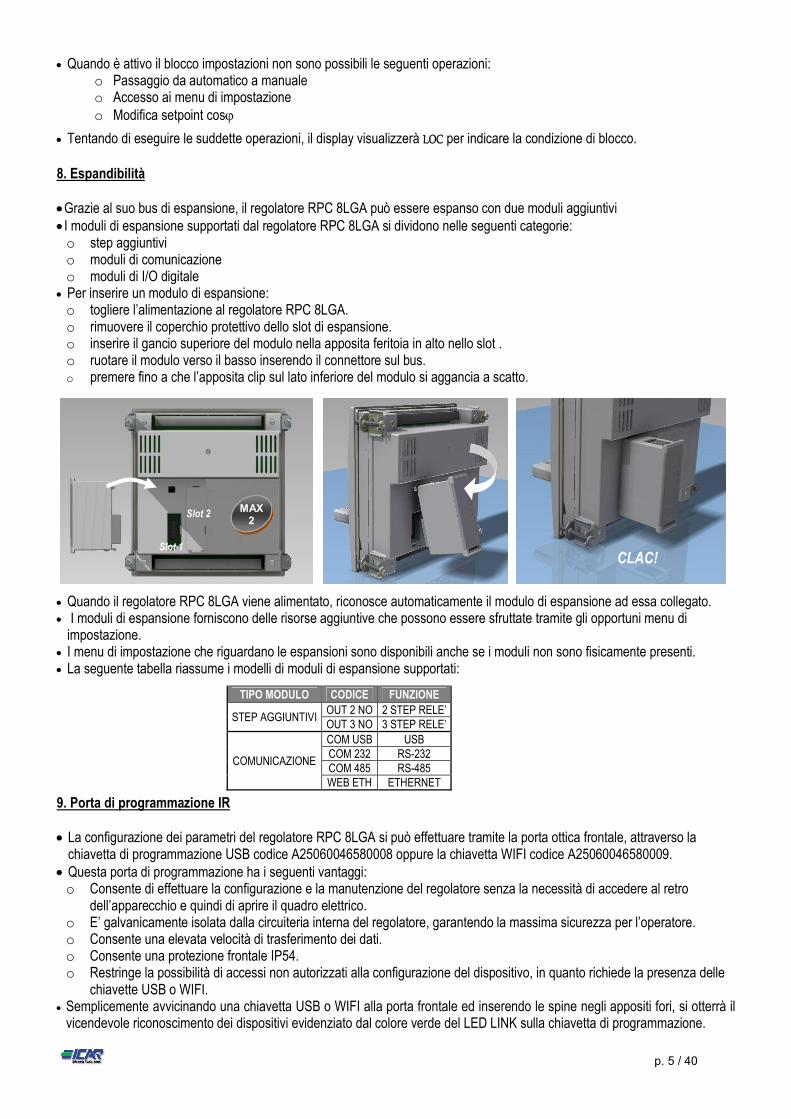
8. Espandibilità Grazie al suo bus di espansione, il regolatore RPC 8LGA può essere espanso con due moduli aggiuntivi I moduli di espansione supportati dal regolatore RPC 8LGA si dividono nelle seguenti categorie: o step aggiuntivi o moduli di comunicazione o moduli di I/O digitale
Per inserire un modulo di espansione: o togliere l’alimentazione al regolatore RPC 8LGA. o rimuovere il coperchio protettivo dello slot di espansione. o inserire il gancio superiore del modulo nella apposita feritoia in alto nello slot . o ruotare il modulo verso il basso inserendo il connettore sul bus. o premere fino a che l’apposita clip sul lato inferiore del modulo si aggancia a scatto.
Quando il regolatore RPC 8LGA viene alimentato, riconosce automaticamente il modulo di espansione ad essa collegato. I moduli di espansione forniscono delle risorse aggiuntive che possono essere sfruttate tramite gli opportuni menu di
impostazione. I menu di impostazione che riguardano le espansioni sono disponibili anche se i moduli non sono fisicamente presenti. La seguente tabella riassume i modelli di moduli di espansione supportati: 9. Porta di programmazione IR La configurazione dei parametri del regolatore RPC 8LGA si può effettuare tramite la porta ottica frontale, attraverso la
chiavetta di programmazione USB codice A25060046580008 oppure la chiavetta WIFI codice A25060046580009. Questa porta di programmazione ha i seguenti vantaggi: o Consente di effettuare la configurazione e la manutenzione del regolatore senza la necessità di accedere al retro
dell’apparecchio e quindi di aprire il quadro elettrico. o E’ galvanicamente isolata dalla circuiteria interna del regolatore, garantendo la massima sicurezza per l’operatore. o Consente una elevata velocità di trasferimento dei dati. o Consente una protezione frontale IP54. o Restringe la possibilità di accessi non autorizzati alla configurazione del dispositivo, in quanto richiede la presenza delle
chiavette USB o WIFI. Semplicemente avvicinando una chiavetta USB o WIFI alla porta frontale ed inserendo le spine negli appositi fori, si otterrà il
vicendevole riconoscimento dei dispositivi evidenziato dal colore verde del LED LINK sulla chiavetta di programmazione.
TIPO MODULO CODICE FUNZIONE
STEP AGGIUNTIVI OUT 2 NO 2 STEP RELE’ OUT 3 NO 3 STEP RELE’
COMUNICAZIONE
COM USB USB COM 232 RS-232 COM 485 RS-485 WEB ETH ETHERNET
CLAC! Slot 1
Slot 2 MAX 2
p. 6 / 40
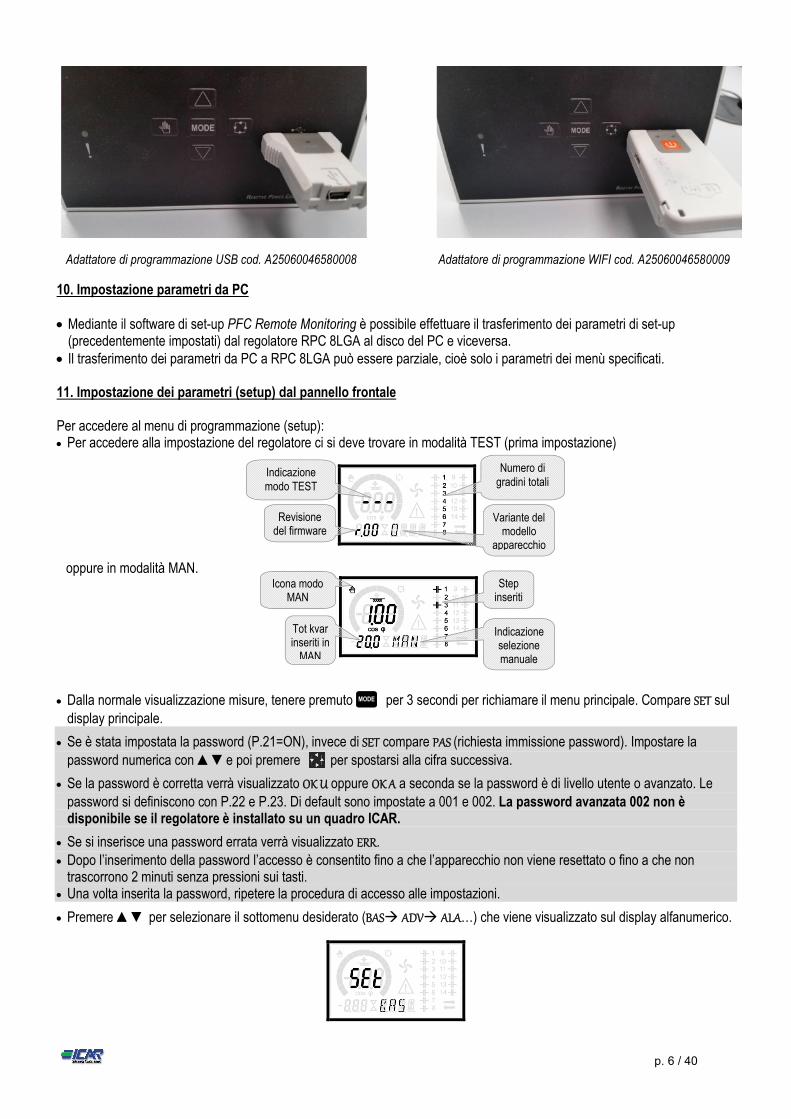
Adattatore di programmazione USB cod. A25060046580008 Adattatore di programmazione WIFI cod. A25060046580009
10. Impostazione parametri da PC Mediante il software di set-up PFC Remote Monitoring è possibile effettuare il trasferimento dei parametri di set-up
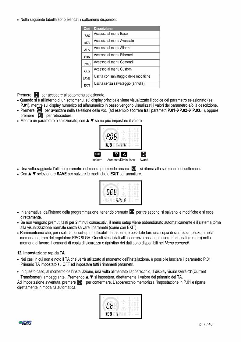
(precedentemente impostati) dal regolatore RPC 8LGA al disco del PC e viceversa. Il trasferimento dei parametri da PC a RPC 8LGA può essere parziale, cioè solo i parametri dei menù specificati. 11. Impostazione dei parametri (setup) dal pannello frontale Per accedere al menu di programmazione (setup): Per accedere alla impostazione del regolatore ci si deve trovare in modalità TEST (prima impostazione)
oppure in modalità MAN.
Dalla normale visualizzazione misure, tenere premuto per 3 secondi per richiamare il menu principale. Compare SET sul display principale.
Se è stata impostata la password (P.21=ON), invece di SET compare PAS (richiesta immissione password). Impostare la
password numerica con ▲▼e poi premere per spostarsi alla cifra successiva.
Se la password è corretta verrà visualizzato OK U oppure OK A a seconda se la password è di livello utente o avanzato. Le password si definiscono con P.22 e P.23. Di default sono impostate a 001 e 002. La password avanzata 002 non è disponibile se il regolatore è installato su un quadro ICAR.
Se si inserisce una password errata verrà visualizzato ERR. Dopo l’inserimento della password l’accesso è consentito fino a che l’apparecchio non viene resettato o fino a che non
trascorrono 2 minuti senza pressioni sui tasti. Una volta inserita la password, ripetere la procedura di accesso alle impostazioni.
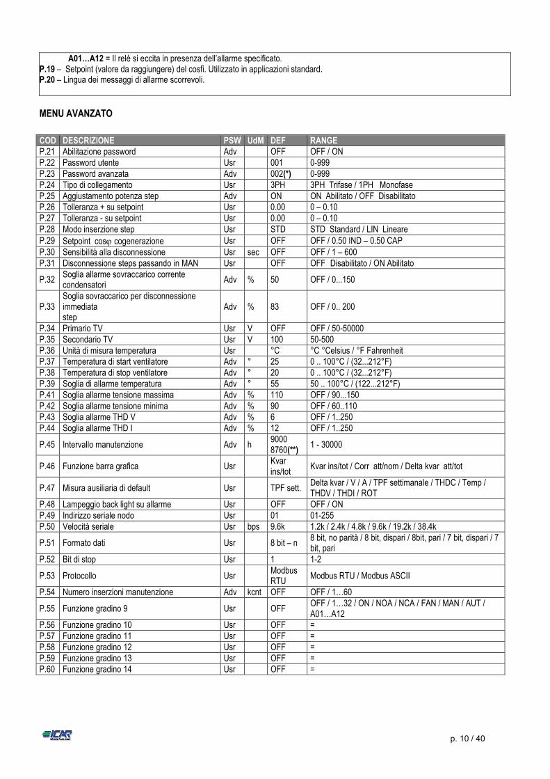
Premere ▲▼ per selezionare il sottomenu desiderato (BAS ADV ALA…) che viene visualizzato sul display alfanumerico.
MODE
Indicazione modo TEST
Numero di gradini totali
Revisione del firmware
Variante del modello
apparecchio
Icona modo MAN
Step inseriti
Tot kvar inseriti in
MAN
Indicazione selezione manuale
p. 7 / 40
Nella seguente tabella sono elencati i sottomenu disponibili:
Cod Descrizione
BAS Accesso al menu Base
ADV Accesso al menu Avanzato
ALA Accesso al menu Allarmi
FUN Accesso al menu Ethernet
CMD Accesso al menu Comandi
CUS Accesso al menu Custom
SAVE Uscita con salvataggio delle modifiche
EXIT Uscita senza salvataggio (annulla)
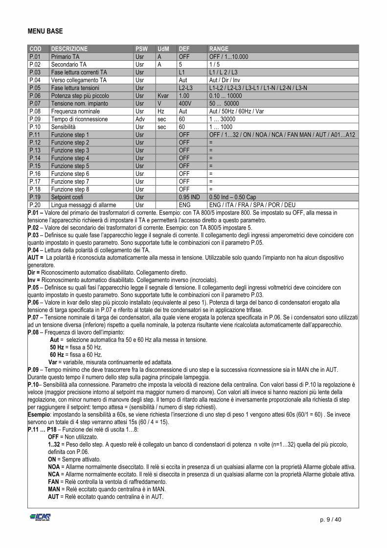
Premere per accedere al sottomenu selezionato. Quando si è all’interno di un sottomenu, sul display principale viene visualizzato il codice del parametro selezionato (es.
P.01), mentre sui display numerico ed alfanumerico in basso vengono visualizzati i valori del parametro e/o la descrizione. Premere per avanzare nella selezione delle voci (ad esempio scorrere fra i parametri P.01P.02 P.03…), oppure
premere per retrocedere. Mentre un parametro è selezionato, con ▲▼se ne può impostare il valore.
Indietro Aumenta/Diminuisce Avanti
Una volta raggiunta l’ultimo parametro del menu, premendo ancora si ritorna alla selezione dei sottomenu. Con ▲▼selezionare SAVE per salvare le modifiche o EXIT per annullare.
In alternativa, dall’interno della programmazione, tenendo premuto per tre secondi si salvano le modifiche e si esce direttamente.
Se non vengono premuti tasti per 2 minuti consecutivi, il menu setup viene abbandonato automaticamente e il sistema torna alla visualizzazione normale senza salvare i parametri (come con EXIT).
Rammentiamo che, per i soli dati di set-up modificabili da tastiera, è possibile fare una copia di sicurezza (backup) nella memoria eeprom del regolatore RPC 8LGA. Questi stessi dati all’occorrenza possono essere ripristinati (restore) nella memoria di lavoro. I comandi di copia di sicurezza e ripristino dei dati sono disponibili nel Menu comandi.
12. Impostazione rapida TA
Nei casi in cui non è noto il TA che verrà utilizzato al momento dell’installazione, è possibile lasciare il parametro P.01 Primario TA impostato su OFF ed impostare tutti i rimanenti parametri.
In questo caso, al momento dell’installazione, una volta alimentato l’apparecchio, il display visualizzerà CT (Current Transformer) lampeggiante. Premendo ▲▼si imposterà, direttamente il valore del primario del TA.
Ad impostazione avvenuta, premere per confermare. L’apparecchio memorizza l’impostazione in P.01 e riparte direttamente in modalità automatica.
MODE ▼ ▲

p. 8 / 40
13. Tabella dei parametri Di seguito vengono riportati tutti i parametri di programmazione disponibili in forma tabellare. Per ogni parametro sono indicati
l’intervallo di impostazione possibile ed il default di fabbrica, oltre ad una spiegazione della funzionalità del parametro. La descrizione del parametro visibile sul display può in qualche caso differire da quanto riportato in tabella a causa del ridotto numero di caratteri disponibile. Il codice del parametro vale comunque come riferimento.
Nota: i parametri evidenziati nella tabella con uno sfondo ombreggiato sono essenziali al funzionamento dell’impianto, rappresentano quindi la programmazione minima indispensabile per la messa in funzione.
p. 9 / 40
MENU BASE
COD DESCRIZIONE PSW UdM DEF RANGE P.01 Primario TA Usr A OFF OFF / 1...10.000 P.02 Secondario TA Usr A 5 1 / 5 P.03 Fase lettura correnti TA Usr L1 L1 / L 2 / L3 P.04 Verso collegamento TA Usr Aut Aut / Dir / Inv P.05 Fase lettura tensioni Usr L2-L3 L1-L2 / L2-L3 / L3-L1 / L1-N / L2-N / L3-N P.06 Potenza step più piccolo Usr Kvar 1.00 0.10 ... 10000 P.07 Tensione nom. impianto Usr V 400V 50 ... 50000 P.08 Frequenza nominale Usr Hz Aut Aut / 50Hz / 60Hz / Var P.09 Tempo di riconnessione Adv sec 60 1 … 30000 P.10 Sensibilità Usr sec 60 1 … 1000
P.11 Funzione step 1 Usr OFF OFF / 1…32 / ON / NOA / NCA / FAN MAN / AUT / A01…A12 P.12 Funzione step 2 Usr OFF = P.13 Funzione step 3 Usr OFF = P.14 Funzione step 4 Usr OFF = P.15 Funzione step 5 Usr OFF = P.16 Funzione step 6 Usr OFF = P.17 Funzione step 7 Usr OFF = P.18 Funzione step 8 Usr OFF = P.19 Setpoint cosfi Usr 0.95 IND 0.50 Ind – 0.50 Cap P.20 Lingua messaggi di allarme Usr ENG ENG / ITA / FRA / SPA / POR / DEU
P.01 – Valore del primario dei trasformatori di corrente. Esempio: con TA 800/5 impostare 800. Se impostato su OFF, alla messa in tensione l’apparecchio richieerà di impostare il TA e permetterà l’accesso diretto a questo parametro. P.02 – Valore del secondario dei trasformatori di corrente. Esempio: con TA 800/5 impostare 5. P.03 – Definisce su quale fase l’apparecchio legge il segnale di corrente. Il collegamento degli ingressi amperometrici deve coincidere con quanto impostato in questo parametro. Sono supportate tutte le combinazioni con il parametro P.05. P.04 – Lettura della polarità di collegamento dei TA. AUT = La polarità è riconosciuta automaticamente alla messa in tensione. Utilizzabile solo quando l’impianto non ha alcun dispositivo generatore. Dir = Riconoscimento automatico disabilitato. Collegamento diretto. Inv = Riconoscimento automatico disabilitato. Collegamento inverso (incrociato). P.05 – Definisce su quali fasi l’apparecchio legge il segnale di tensione. Il collegamento degli ingressi voltmetrici deve coincidere con quanto impostato in questo parametro. Sono supportate tutte le combinazioni con il parametro P.03. P.06 – Valore in kvar dello step più piccolo installato (equivalente al peso 1). Potenza di targa del banco di condensatori erogato alla tensione di targa specificata in P.07 e riferito al totale dei tre condensatori se in applicazione trifase. P.07 – Tensione nominale di targa dei condensatori, alla quale viene erogata la potenza specificata in P.06. Se i condensatori sono utilizzati ad un tensione diversa (inferiore) rispetto a quella nominale, la potenza risultante viene ricalcolata automaticamente dall’apparecchio. P.08 – Frequenza di lavoro dell’impianto: Aut = selezione automatica fra 50 e 60 Hz alla messa in tensione. 50 Hz = fissa a 50 Hz. 60 Hz = fissa a 60 Hz. Var = variabile, misurata continuamente ed adattata. P.09 – Tempo minimo che deve trascorrere fra la disconnessione di uno step e la successiva riconnessione sia in MAN che in AUT. Durante questo tempo il numero dello step sulla pagina principale lampeggia. P.10– Sensibilità alla connessione. Parametro che imposta la velocità di reazione della centralina. Con valori bassi di P.10 la regolazione è veloce (maggior precisione intorno al setpoint ma maggior numero di manovre). Con valori alti invece si hanno reazioni più lente della regolazione, con minor numero di manovre degli step. Il tempo di ritardo alla reazione è inversamente proporzionale alla richiesta di step per raggiungere il setpoint: tempo attesa = (sensibilità / numero di step richiesti). Esempio: impostando la sensibilità a 60s, se viene richiesta l’inserzione di uno step di peso 1 vengono attesi 60s (60/1 = 60) . Se invece servono un totale di 4 step verranno attesi 15s (60 / 4 = 15). P.11 … P18 – Funzione dei relè di uscita 1…8:
OFF = Non utilizzato. 1..32 = Peso dello step. A questo relè è collegato un banco di condenstaori di potenza n volte (n=1…32) quella del più piccolo, definita con P.06. ON = Sempre attivato. NOA = Allarme normalmente diseccitato. Il relè si eccita in presenza di un qualsiasi allarme con la proprietà Allarme globale attiva. NCA = Allarme normalmente eccitato. Il relè si diseccita in presenza di un qualsiasi allarme con la proprietà Allarme globale attiva. FAN = Relè controlla la ventola di raffreddamento. MAN = Relè eccitato quando centralina è in MAN. AUT = Relè eccitato quando centralina è in AUT.
p. 10 / 40
MENU AVANZATO
A01…A12 = Il relè si eccita in presenza dell’allarme specificato. P.19 – Setpoint (valore da raggiungere) del cosfi. Utilizzato in applicazioni standard. P.20 – Lingua dei messaggi di allarme scorrevoli.
COD DESCRIZIONE PSW UdM DEF RANGE P.21 Abilitazione password Adv OFF OFF / ON P.22 Password utente Usr 001 0-999 P.23 Password avanzata Adv 002(*) 0-999 P.24 Tipo di collegamento Usr 3PH 3PH Trifase / 1PH Monofase P.25 Aggiustamento potenza step Adv ON ON Abilitato / OFF Disabilitato P.26 Tolleranza + su setpoint Usr 0.00 0 – 0.10 P.27 Tolleranza - su setpoint Usr 0.00 0 – 0.10 P.28 Modo inserzione step Usr STD STD Standard / LIN Lineare P.29 Setpoint cos cogenerazione Usr OFF OFF / 0.50 IND – 0.50 CAP P.30 Sensibilità alla disconnessione Usr sec OFF OFF / 1 – 600 P.31 Disconnessione steps passando in MAN Usr OFF OFF Disabilitato / ON Abilitato
P.32 Soglia allarme sovraccarico corrente condensatori
Adv % 50 OFF / 0...150
P.33 Soglia sovraccarico per disconnessione immediata step
Adv % 83 OFF / 0.. 200
P.34 Primario TV Usr V OFF OFF / 50-50000 P.35 Secondario TV Usr V 100 50-500 P.36 Unità di misura temperatura Usr °C °C °Celsius / °F Fahrenheit P.37 Temperatura di start ventilatore Adv ° 25 0 .. 100°C / (32...212°F) P.38 Temperatura di stop ventilatore Adv ° 20 0 .. 100°C / (32...212°F) P.39 Soglia di allarme temperatura Adv ° 55 50 .. 100°C / (122...212°F) P.41 Soglia allarme tensione massima Adv % 110 OFF / 90...150 P.42 Soglia allarme tensione minima Adv % 90 OFF / 60..110 P.43 Soglia allarme THD V Adv % 6 OFF / 1..250 P.44 Soglia allarme THD I Adv % 12 OFF / 1..250
P.45 Intervallo manutenzione Adv h 9000 8760(**)
1 - 30000
P.46 Funzione barra grafica Usr Kvar ins/tot
Kvar ins/tot / Corr att/nom / Delta kvar att/tot
P.47 Misura ausiliaria di default Usr TPF sett. Delta kvar / V / A / TPF settimanale / THDC / Temp / THDV / THDI / ROT
P.48 Lampeggio back light su allarme Usr OFF OFF / ON P.49 Indirizzo seriale nodo Usr 01 01-255 P.50 Velocità seriale Usr bps 9.6k 1.2k / 2.4k / 4.8k / 9.6k / 19.2k / 38.4k
P.51 Formato dati Usr 8 bit – n 8 bit, no parità / 8 bit, dispari / 8bit, pari / 7 bit, dispari / 7 bit, pari
P.52 Bit di stop Usr 1 1-2
P.53 Protocollo Usr Modbus RTU
Modbus RTU / Modbus ASCII
P.54 Numero inserzioni manutenzione Adv kcnt OFF OFF / 1…60
P.55 Funzione gradino 9 Usr OFF OFF / 1…32 / ON / NOA / NCA / FAN / MAN / AUT / A01…A12
P.56 Funzione gradino 10 Usr OFF = P.57 Funzione gradino 11 Usr OFF = P.58 Funzione gradino 12 Usr OFF = P.59 Funzione gradino 13 Usr OFF = P.60 Funzione gradino 14 Usr OFF =
p. 11 / 40
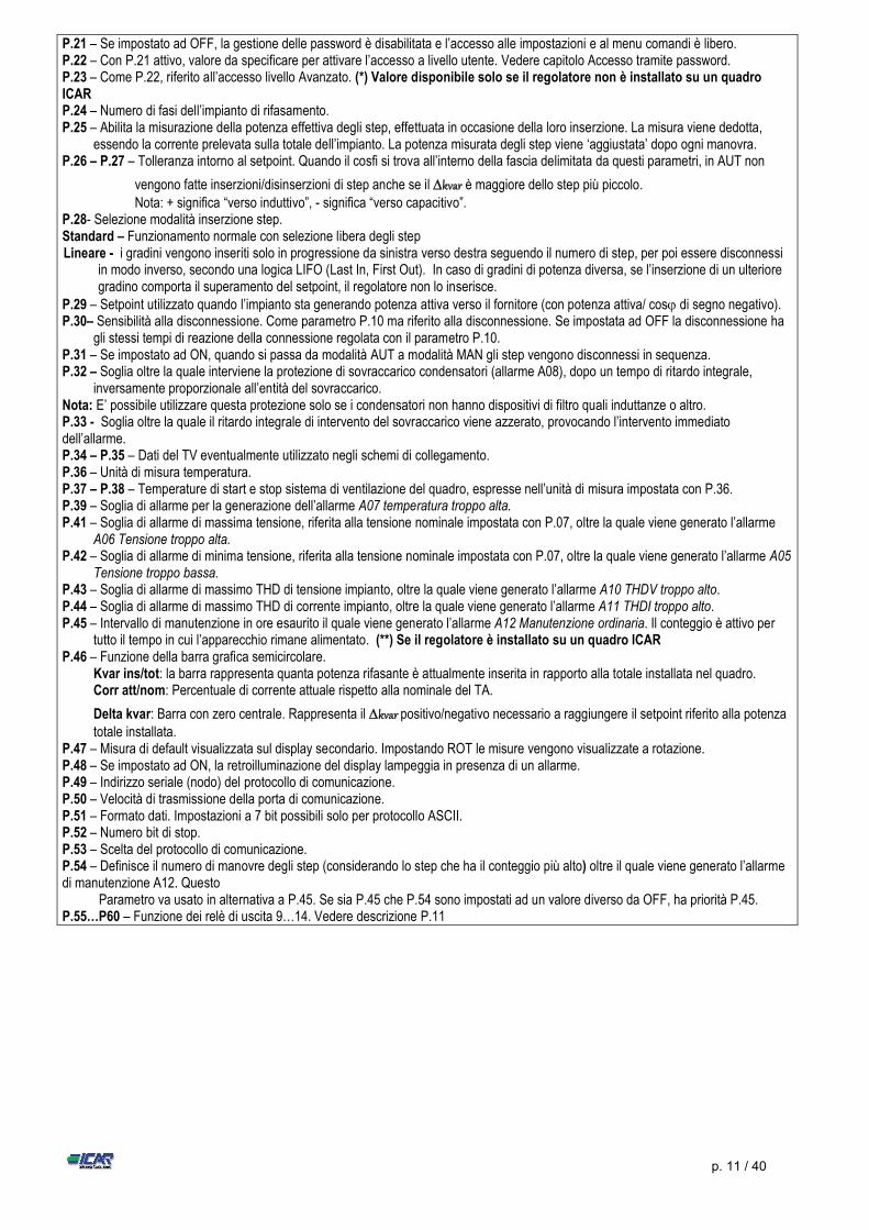
P.21 – Se impostato ad OFF, la gestione delle password è disabilitata e l’accesso alle impostazioni e al menu comandi è libero. P.22 – Con P.21 attivo, valore da specificare per attivare l’accesso a livello utente. Vedere capitolo Accesso tramite password. P.23 – Come P.22, riferito all’accesso livello Avanzato. (*) Valore disponibile solo se il regolatore non è installato su un quadro ICAR P.24 – Numero di fasi dell’impianto di rifasamento. P.25 – Abilita la misurazione della potenza effettiva degli step, effettuata in occasione della loro inserzione. La misura viene dedotta,
essendo la corrente prelevata sulla totale dell’impianto. La potenza misurata degli step viene ‘aggiustata’ dopo ogni manovra. P.26 – P.27 – Tolleranza intorno al setpoint. Quando il cosfi si trova all’interno della fascia delimitata da questi parametri, in AUT non
vengono fatte inserzioni/disinserzioni di step anche se il kvar è maggiore dello step più piccolo. Nota: + significa “verso induttivo”, - significa “verso capacitivo”.
P.28- Selezione modalità inserzione step. Standard – Funzionamento normale con selezione libera degli step Lineare - i gradini vengono inseriti solo in progressione da sinistra verso destra seguendo il numero di step, per poi essere disconnessi
in modo inverso, secondo una logica LIFO (Last In, First Out). In caso di gradini di potenza diversa, se l’inserzione di un ulteriore gradino comporta il superamento del setpoint, il regolatore non lo inserisce.
P.29 – Setpoint utilizzato quando l’impianto sta generando potenza attiva verso il fornitore (con potenza attiva/ cos di segno negativo). P.30– Sensibilità alla disconnessione. Come parametro P.10 ma riferito alla disconnessione. Se impostata ad OFF la disconnessione ha
gli stessi tempi di reazione della connessione regolata con il parametro P.10. P.31 – Se impostato ad ON, quando si passa da modalità AUT a modalità MAN gli step vengono disconnessi in sequenza. P.32 – Soglia oltre la quale interviene la protezione di sovraccarico condensatori (allarme A08), dopo un tempo di ritardo integrale,
inversamente proporzionale all’entità del sovraccarico. Nota: E’ possibile utilizzare questa protezione solo se i condensatori non hanno dispositivi di filtro quali induttanze o altro. P.33 - Soglia oltre la quale il ritardo integrale di intervento del sovraccarico viene azzerato, provocando l’intervento immediato dell’allarme. P.34 – P.35 – Dati del TV eventualmente utilizzato negli schemi di collegamento. P.36 – Unità di misura temperatura. P.37 – P.38 – Temperature di start e stop sistema di ventilazione del quadro, espresse nell’unità di misura impostata con P.36. P.39 – Soglia di allarme per la generazione dell’allarme A07 temperatura troppo alta. P.41 – Soglia di allarme di massima tensione, riferita alla tensione nominale impostata con P.07, oltre la quale viene generato l’allarme
A06 Tensione troppo alta. P.42 – Soglia di allarme di minima tensione, riferita alla tensione nominale impostata con P.07, oltre la quale viene generato l’allarme A05
Tensione troppo bassa. P.43 – Soglia di allarme di massimo THD di tensione impianto, oltre la quale viene generato l’allarme A10 THDV troppo alto. P.44 – Soglia di allarme di massimo THD di corrente impianto, oltre la quale viene generato l’allarme A11 THDI troppo alto. P.45 – Intervallo di manutenzione in ore esaurito il quale viene generato l’allarme A12 Manutenzione ordinaria. Il conteggio è attivo per
tutto il tempo in cui l’apparecchio rimane alimentato. (**) Se il regolatore è installato su un quadro ICAR P.46 – Funzione della barra grafica semicircolare.
Kvar ins/tot: la barra rappresenta quanta potenza rifasante è attualmente inserita in rapporto alla totale installata nel quadro. Corr att/nom: Percentuale di corrente attuale rispetto alla nominale del TA.
Delta kvar: Barra con zero centrale. Rappresenta il kvar positivo/negativo necessario a raggiungere il setpoint riferito alla potenza totale installata.
P.47 – Misura di default visualizzata sul display secondario. Impostando ROT le misure vengono visualizzate a rotazione. P.48 – Se impostato ad ON, la retroilluminazione del display lampeggia in presenza di un allarme. P.49 – Indirizzo seriale (nodo) del protocollo di comunicazione. P.50 – Velocità di trasmissione della porta di comunicazione. P.51 – Formato dati. Impostazioni a 7 bit possibili solo per protocollo ASCII. P.52 – Numero bit di stop. P.53 – Scelta del protocollo di comunicazione. P.54 – Definisce il numero di manovre degli step (considerando lo step che ha il conteggio più alto) oltre il quale viene generato l’allarme di manutenzione A12. Questo Parametro va usato in alternativa a P.45. Se sia P.45 che P.54 sono impostati ad un valore diverso da OFF, ha priorità P.45. P.55…P60 – Funzione dei relè di uscita 9…14. Vedere descrizione P.11
p. 12 / 40
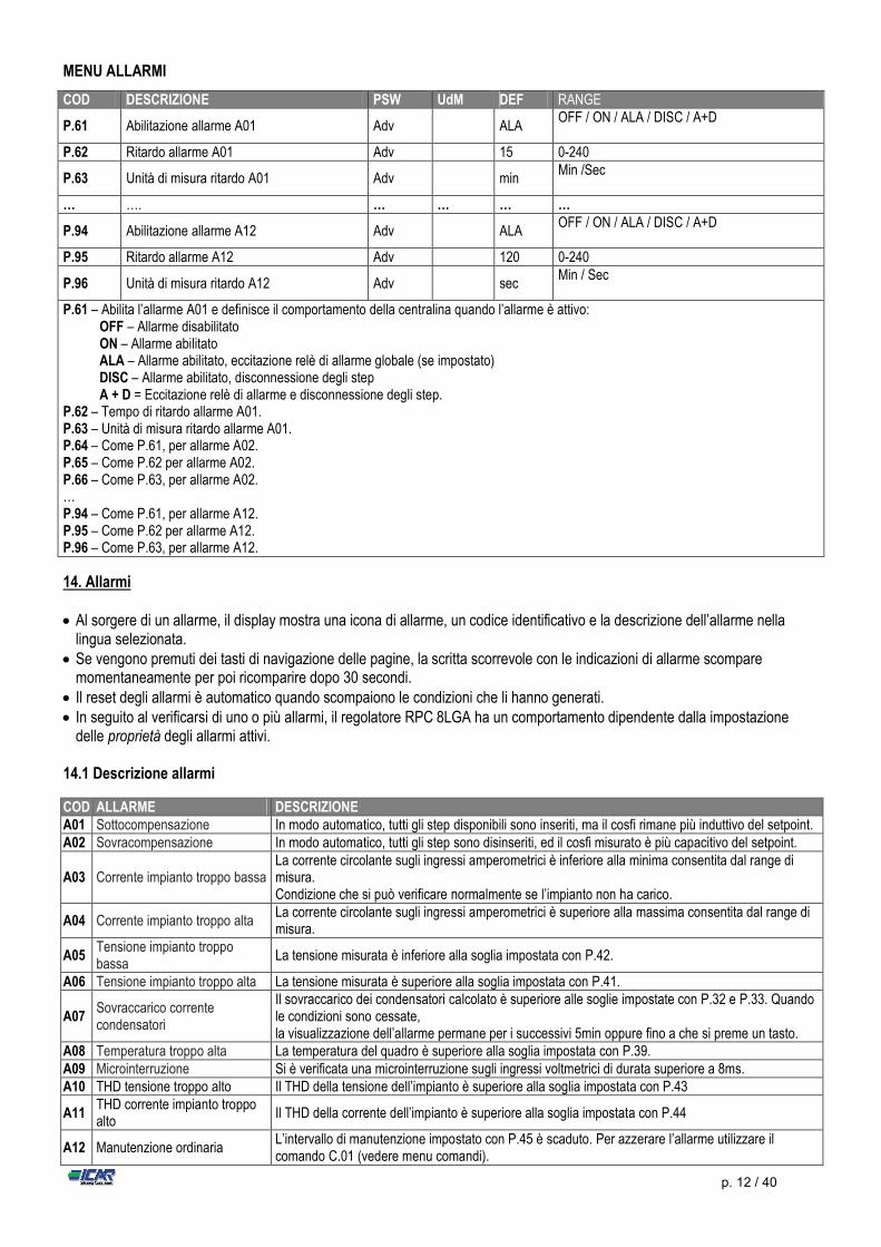
MENU ALLARMI
14. Allarmi Al sorgere di un allarme, il display mostra una icona di allarme, un codice identificativo e la descrizione dell’allarme nella
lingua selezionata. Se vengono premuti dei tasti di navigazione delle pagine, la scritta scorrevole con le indicazioni di allarme scompare
momentaneamente per poi ricomparire dopo 30 secondi. Il reset degli allarmi è automatico quando scompaiono le condizioni che li hanno generati. In seguito al verificarsi di uno o più allarmi, il regolatore RPC 8LGA ha un comportamento dipendente dalla impostazione
delle proprietà degli allarmi attivi. 14.1 Descrizione allarmi
COD ALLARME DESCRIZIONE A01 Sottocompensazione In modo automatico, tutti gli step disponibili sono inseriti, ma il cosfi rimane più induttivo del setpoint. A02 Sovracompensazione In modo automatico, tutti gli step sono disinseriti, ed il cosfi misurato è più capacitivo del setpoint.
A03 Corrente impianto troppo bassa La corrente circolante sugli ingressi amperometrici è inferiore alla minima consentita dal range di misura. Condizione che si può verificare normalmente se l’impianto non ha carico.
A04 Corrente impianto troppo alta La corrente circolante sugli ingressi amperometrici è superiore alla massima consentita dal range di misura.
A05 Tensione impianto troppo bassa
La tensione misurata è inferiore alla soglia impostata con P.42.
A06 Tensione impianto troppo alta La tensione misurata è superiore alla soglia impostata con P.41.
A07 Sovraccarico corrente condensatori
Il sovraccarico dei condensatori calcolato è superiore alle soglie impostate con P.32 e P.33. Quando le condizioni sono cessate, la visualizzazione dell’allarme permane per i successivi 5min oppure fino a che si preme un tasto.
A08 Temperatura troppo alta La temperatura del quadro è superiore alla soglia impostata con P.39. A09 Microinterruzione Si è verificata una microinterruzione sugli ingressi voltmetrici di durata superiore a 8ms. A10 THD tensione troppo alto Il THD della tensione dell’impianto è superiore alla soglia impostata con P.43
A11 THD corrente impianto troppo alto
Il THD della corrente dell’impianto è superiore alla soglia impostata con P.44
A12 Manutenzione ordinaria L’intervallo di manutenzione impostato con P.45 è scaduto. Per azzerare l’allarme utilizzare il comando C.01 (vedere menu comandi).
COD DESCRIZIONE PSW UdM DEF RANGE
P.61 Abilitazione allarme A01 Adv ALA OFF / ON / ALA / DISC / A+D
P.62 Ritardo allarme A01 Adv 15 0-240
P.63 Unità di misura ritardo A01 Adv min Min /Sec
… …. … … … …
P.94 Abilitazione allarme A12 Adv ALA OFF / ON / ALA / DISC / A+D
P.95 Ritardo allarme A12 Adv 120 0-240
P.96 Unità di misura ritardo A12 Adv sec Min / Sec
P.61 – Abilita l’allarme A01 e definisce il comportamento della centralina quando l’allarme è attivo: OFF – Allarme disabilitato ON – Allarme abilitato ALA – Allarme abilitato, eccitazione relè di allarme globale (se impostato) DISC – Allarme abilitato, disconnessione degli step A + D = Eccitazione relè di allarme e disconnessione degli step.
P.62 – Tempo di ritardo allarme A01. P.63 – Unità di misura ritardo allarme A01. P.64 – Come P.61, per allarme A02. P.65 – Come P.62 per allarme A02. P.66 – Come P.63, per allarme A02. … P.94 – Come P.61, per allarme A12. P.95 – Come P.62 per allarme A12. P.96 – Come P.63, per allarme A12.
p. 13 / 40
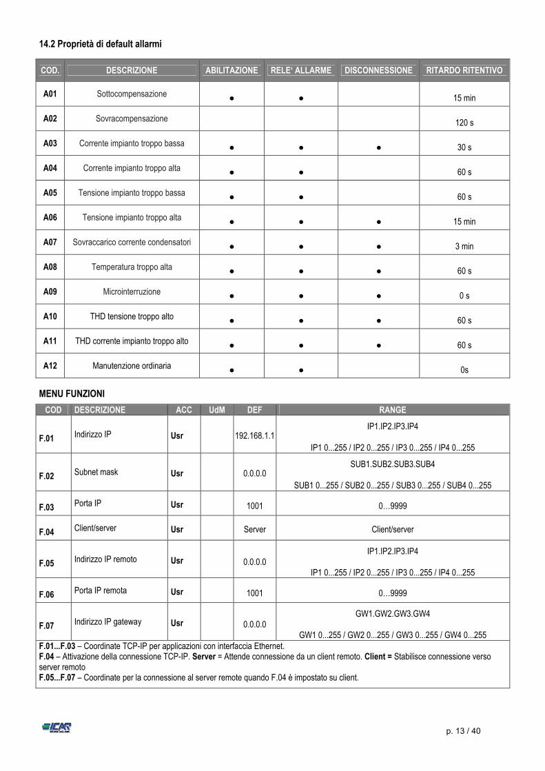
14.2 Proprietà di default allarmi
COD. DESCRIZIONE ABILITAZIONE RELE‘ ALLARME DISCONNESSIONE RITARDO RITENTIVO
A01 Sottocompensazione ● ● 15 min
A02 Sovracompensazione 120 s
A03 Corrente impianto troppo bassa ● ● ● 30 s
A04 Corrente impianto troppo alta ● ● 60 s
A05 Tensione impianto troppo bassa ● ● 60 s
A06 Tensione impianto troppo alta ● ● ● 15 min
A07 Sovraccarico corrente condensatori ● ● ● 3 min
A08 Temperatura troppo alta ● ● ● 60 s
A09 Microinterruzione ● ● ● 0 s
A10 THD tensione troppo alto ● ● ● 60 s
A11 THD corrente impianto troppo alto ● ● ● 60 s
A12 Manutenzione ordinaria ● ● 0s
MENU FUNZIONI
COD DESCRIZIONE ACC UdM DEF RANGE
F.01 Indirizzo IP Usr 192.168.1.1 IP1.IP2.IP3.IP4
IP1 0...255 / IP2 0...255 / IP3 0...255 / IP4 0...255
F.02 Subnet mask Usr 0.0.0.0 SUB1.SUB2.SUB3.SUB4
SUB1 0...255 / SUB2 0...255 / SUB3 0...255 / SUB4 0...255
F.03 Porta IP Usr 1001 0…9999
F.04 Client/server Usr Server Client/server
F.05 Indirizzo IP remoto Usr 0.0.0.0 IP1.IP2.IP3.IP4
IP1 0...255 / IP2 0...255 / IP3 0...255 / IP4 0...255
F.06 Porta IP remota Usr 1001 0…9999
F.07 Indirizzo IP gateway Usr 0.0.0.0 GW1.GW2.GW3.GW4
GW1 0...255 / GW2 0...255 / GW3 0...255 / GW4 0...255 F.01...F.03 – Coordinate TCP-IP per applicazioni con interfaccia Ethernet. F.04 – Attivazione della connessione TCP-IP. Server = Attende connessione da un client remoto. Client = Stabilisce connessione verso server remoto F.05...F.07 – Coordinate per la connessione al server remote quando F.04 è impostato su client.
p. 14 / 40
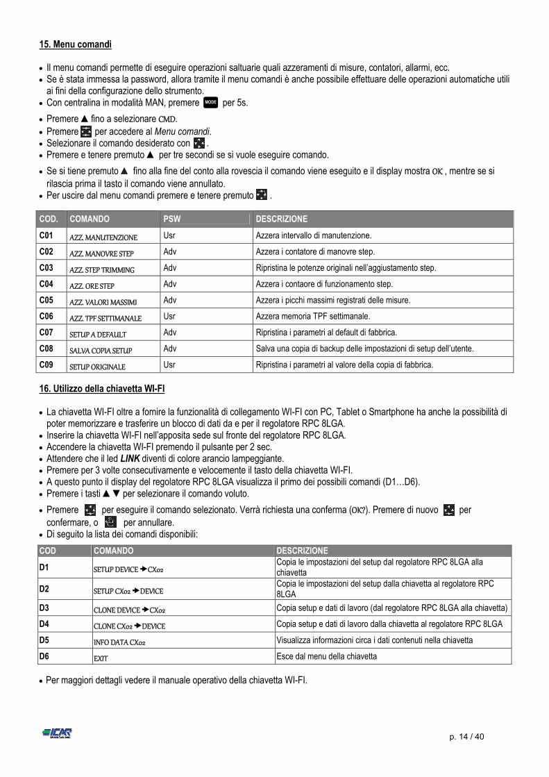
15. Menu comandi Il menu comandi permette di eseguire operazioni saltuarie quali azzeramenti di misure, contatori, allarmi, ecc. Se è stata immessa la password, allora tramite il menu comandi è anche possibile effettuare delle operazioni automatiche utili
ai fini della configurazione dello strumento. Con centralina in modalità MAN, premere per 5s.
Premere ▲fino a selezionare CMD.
Premere per accedere al Menu comandi. Selezionare il comando desiderato con . Premere e tenere premuto ▲ per tre secondi se si vuole eseguire comando.
Se si tiene premuto ▲ fino alla fine del conto alla rovescia il comando viene eseguito e il display mostra OK , mentre se si
rilascia prima il tasto il comando viene annullato. Per uscire dal menu comandi premere e tenere premuto .
COD. COMANDO PSW DESCRIZIONE
C01 AZZ. MANUTENZIONE Usr Azzera intervallo di manutenzione.
C02 AZZ. MANOVRE STEP Adv Azzera i contatore di manovre step.
C03 AZZ. STEP TRIMMING Adv Ripristina le potenze originali nell’aggiustamento step.
C04 AZZ. ORE STEP Adv Azzera i contaore di funzionamento step.
C05 AZZ. VALORI MASSIMI Adv Azzera i picchi massimi registrati delle misure.
C06 AZZ. TPF SETTIMANALE Usr Azzera memoria TPF settimanale.
C07 SETUP A DEFAULT Adv Ripristina i parametri al default di fabbrica.
C08 SALVA COPIA SETUP Adv Salva una copia di backup delle impostazioni di setup dell’utente.
C09 SETUP ORIGINALE Usr Ripristina i parametri al valore della copia di fabbrica.
16. Utilizzo della chiavetta WI-FI La chiavetta WI-FI oltre a fornire la funzionalità di collegamento WI-FI con PC, Tablet o Smartphone ha anche la possibilità di
poter memorizzare e trasferire un blocco di dati da e per il regolatore RPC 8LGA. Inserire la chiavetta WI-FI nell’apposita sede sul fronte del regolatore RPC 8LGA. Accendere la chiavetta WI-FI premendo il pulsante per 2 sec. Attendere che il led LINK diventi di colore arancio lampeggiante. Premere per 3 volte consecutivamente e velocemente il tasto della chiavetta WI-FI. A questo punto il display del regolatore RPC 8LGA visualizza il primo dei possibili comandi (D1…D6). Premere i tasti ▲▼per selezionare il comando voluto.
Premere per eseguire il comando selezionato. Verrà richiesta una conferma (OK?). Premere di nuovo per
confermare, o per annullare. Di seguito la lista dei comandi disponibili:
COD COMANDO DESCRIZIONE
D1 SETUP DEVICE CX02 Copia le impostazioni del setup dal regolatore RPC 8LGA alla chiavetta
D2 SETUP CX02 DEVICE Copia le impostazioni del setup dalla chiavetta al regolatore RPC 8LGA
D3 CLONE DEVICE CX02 Copia setup e dati di lavoro (dal regolatore RPC 8LGA alla chiavetta)
D4 CLONE CX02 DEVICE Copia setup e dati di lavoro dalla chiavetta al regolatore RPC 8LGA
D5 INFO DATA CX02 Visualizza informazioni circa i dati contenuti nella chiavetta
D6 EXIT Esce dal menu della chiavetta
Per maggiori dettagli vedere il manuale operativo della chiavetta WI-FI.
MODE
p. 15 / 40
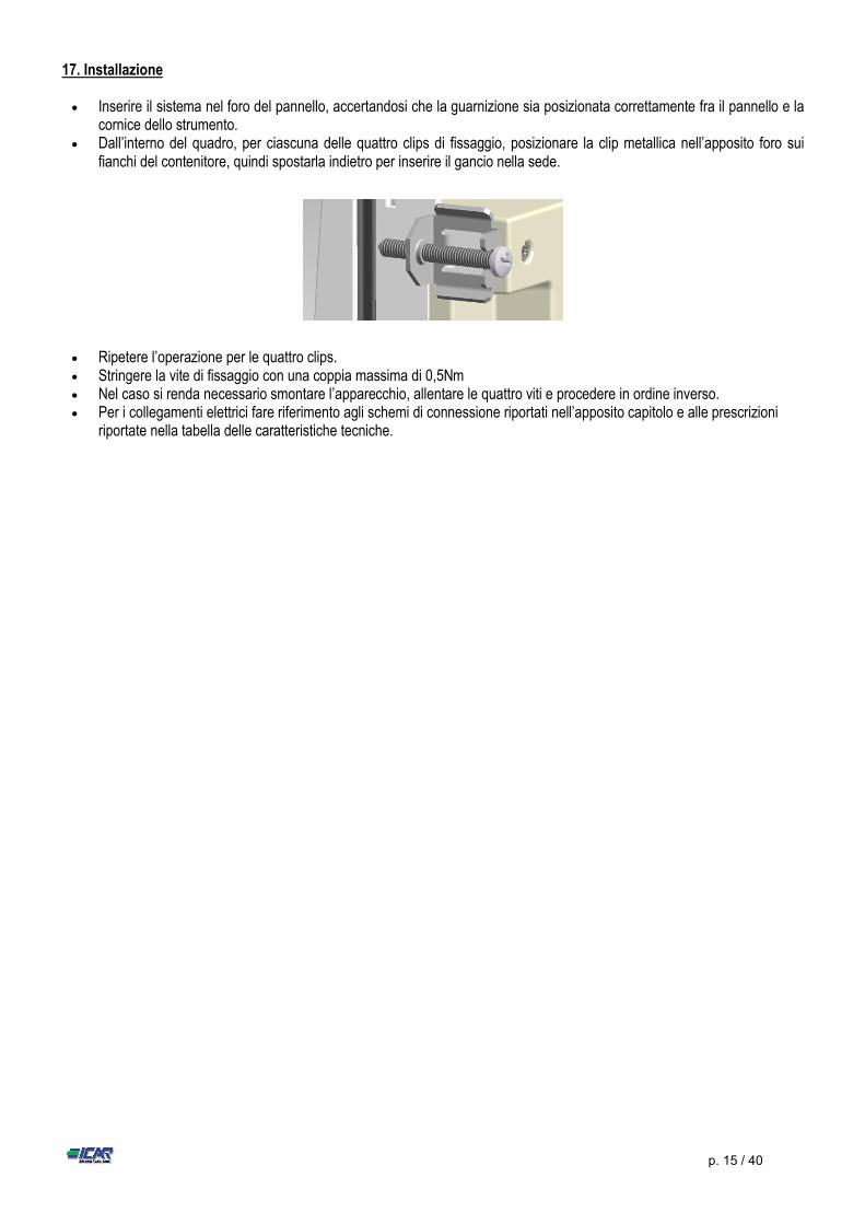
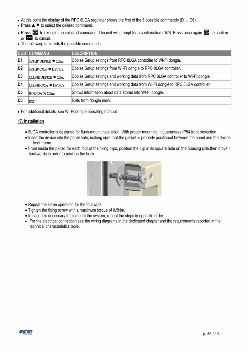
17. Installazione Inserire il sistema nel foro del pannello, accertandosi che la guarnizione sia posizionata correttamente fra il pannello e la
cornice dello strumento. Dall’interno del quadro, per ciascuna delle quattro clips di fissaggio, posizionare la clip metallica nell’apposito foro sui
fianchi del contenitore, quindi spostarla indietro per inserire il gancio nella sede.
Ripetere l’operazione per le quattro clips. Stringere la vite di fissaggio con una coppia massima di 0,5Nm Nel caso si renda necessario smontare l’apparecchio, allentare le quattro viti e procedere in ordine inverso. Per i collegamenti elettrici fare riferimento agli schemi di connessione riportati nell’apposito capitolo e alle prescrizioni
riportate nella tabella delle caratteristiche tecniche.
p. 16 / 40
17. Schemi di collegamento
ATTENZIONE!!
Togliere sempre tensione quando si opera sui morsetti.
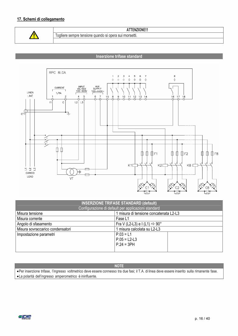
Inserzione trifase standard
INSERZIONE TRIFASE STANDARD (default) Configurazione di default per applicazioni standard
Misura tensione 1 misura di tensione concatenata L2-L3 Misura corrente Fase L1 Angolo di sfasamento Fra V (L2-L3) e I (L1) 90° Misura sovraccarico condensatori 1 misura calcolata su L2-L3 Impostazione parametri P.03 = L1
P.05 = L2-L3 P.24 = 3PH
NOTE
Per inserzione trifase, l’ingresso voltmetrico deve essere connesso tra due fasi; il T.A. di linea deve essere inserito sulla rimanente fase.
La polarità dell’ingresso amperometrico è ininfluente.
p. 17 / 40
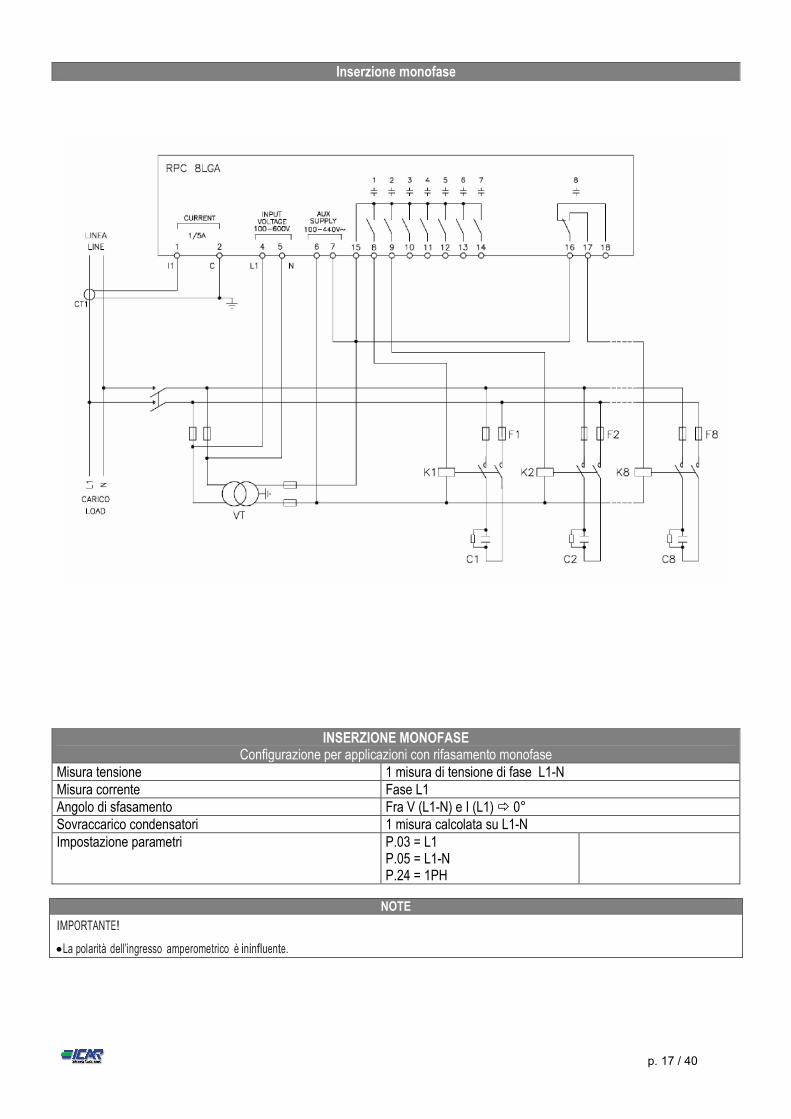
INSERZIONE MONOFASE Configurazione per applicazioni con rifasamento monofase
Misura tensione 1 misura di tensione di fase L1-N Misura corrente Fase L1 Angolo di sfasamento Fra V (L1-N) e I (L1) 0° Sovraccarico condensatori 1 misura calcolata su L1-N Impostazione parametri P.03 = L1
P.05 = L1-N P.24 = 1PH
NOTE
IMPORTANTE!
La polarità dell’ingresso amperometrico è ininfluente.
Inserzione monofase
p. 18 / 40
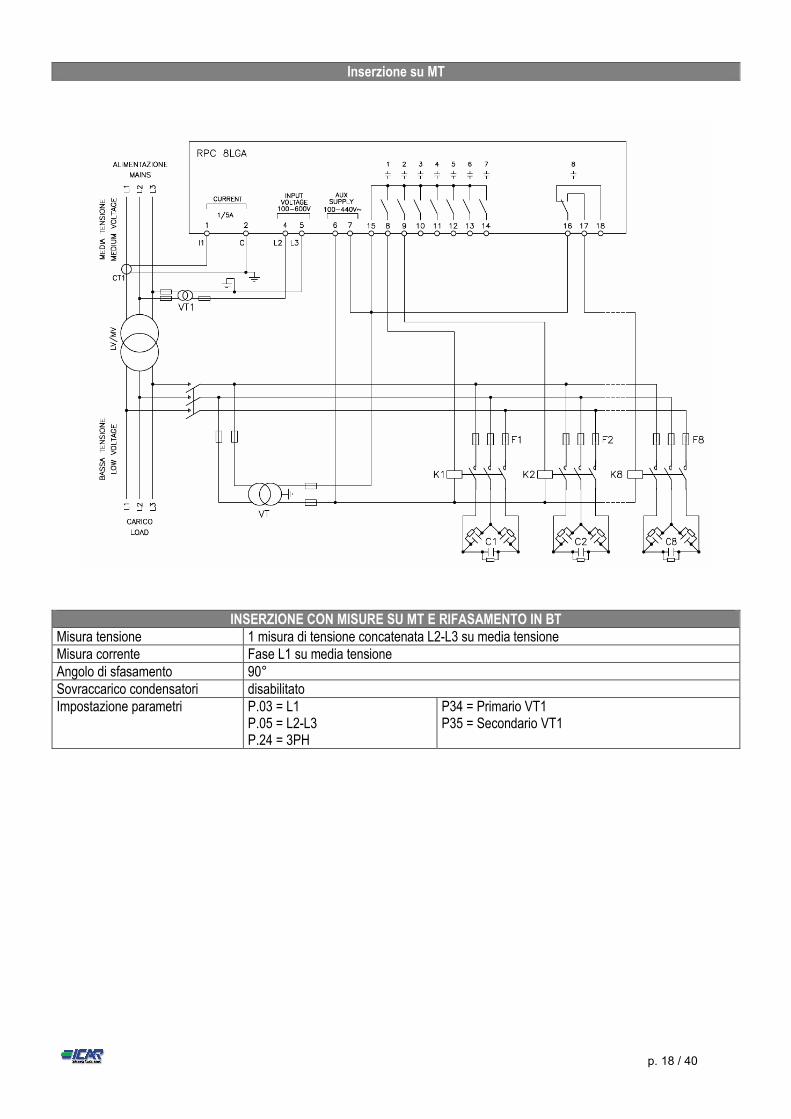
INSERZIONE CON MISURE SU MT E RIFASAMENTO IN BT Misura tensione 1 misura di tensione concatenata L2-L3 su media tensione Misura corrente Fase L1 su media tensione Angolo di sfasamento 90° Sovraccarico condensatori disabilitato Impostazione parametri P.03 = L1
P.05 = L2-L3 P.24 = 3PH
P34 = Primario VT1 P35 = Secondario VT1
Inserzione su MT
p. 19 / 40
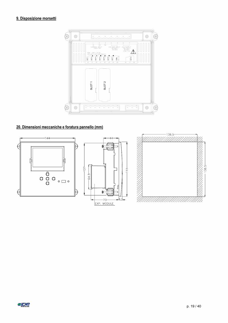
9. Disposizione morsetti
SL
OT
1
SL
OT
2
OU
T 1
OU
T 2
OU
T 3
OU
T 4
OU
T 5
OU
T 6
OU
T 7
OU
T 8
CO
M
20. Dimensioni meccaniche e foratura pannello (mm)
p. 20 / 40
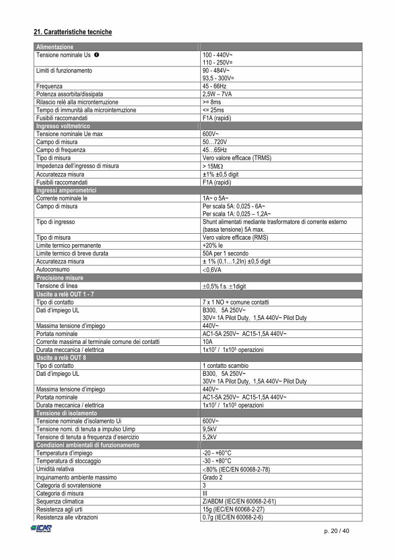
21. Caratteristiche tecniche
Alimentazione Tensione nominale Us 100 - 440V~
110 - 250V= Limiti di funzionamento 90 - 484V~
93,5 - 300V= Frequenza 45 - 66Hz Potenza assorbita/dissipata 2,5W – 7VA Rilascio relè alla micronterruzione >= 8ms Tempo di immunità alla microinterruzione <= 25ms Fusibili raccomandati F1A (rapidi) Ingresso voltmetrico Tensione nominale Ue max 600V~ Campo di misura 50…720V Campo di frequenza 45…65Hz Tipo di misura Vero valore efficace (TRMS) Impedenza dell’ingresso di misura > 15M Accuratezza misura ±1% ±0,5 digit Fusibili raccomandati F1A (rapidi) Ingressi amperometrici Corrente nominale Ie 1A~ o 5A~ Campo di misura Per scala 5A: 0,025 - 6A~
Per scala 1A: 0,025 – 1,2A~ Tipo di ingresso Shunt alimentati mediante trasformatore di corrente esterno
(bassa tensione) 5A max. Tipo di misura Vero valore efficace (RMS) Limite termico permanente +20% Ie Limite termico di breve durata 50A per 1 secondo Accuratezza misura ± 1% (0,1…1,2In) ±0,5 digit Autoconsumo 0,6VA Precisione misure Tensione di linea 0,5% f.s. 1digit Uscite a relè OUT 1 - 7 Tipo di contatto 7 x 1 NO + comune contatti Dati d’impiego UL B300, 5A 250V~
30V= 1A Pilot Duty, 1,5A 440V~ Pilot Duty Massima tensione d’impiego 440V~ Portata nominale AC1-5A 250V~ AC15-1,5A 440V~ Corrente massima al terminale comune dei contatti 10A Durata meccanica / elettrica 1x10⁷ / 1x10⁵ operazioni Uscite a relè OUT 8 Tipo di contatto 1 contatto scambio Dati d’impiego UL B300, 5A 250V~
30V= 1A Pilot Duty, 1,5A 440V~ Pilot Duty Massima tensione d’impiego 440V~ Portata nominale AC1-5A 250V~ AC15-1,5A 440V~ Durata meccanica / elettrica 1x10⁷ / 1x10⁵ operazioni Tensione di isolamento Tensione nominale d’isolamento Ui 600V~ Tensione nomi. di tenuta a impulso Uimp 9,5kV Tensione di tenuta a frequenza d’esercizio 5,2kV Condizioni ambientali di funzionamento Temperatura d’impiego -20 - +60°C Temperatura di stoccaggio -30 - +80°C Umidità relativa 80% (IEC/EN 60068-2-78) Inquinamento ambiente massimo Grado 2 Categoria di sovratensione 3 Categoria di misura III Sequenza climatica Z/ABDM (IEC/EN 60068-2-61) Resistenza agli urti 15g (IEC/EN 60068-2-27) Resistenza alle vibrazioni 0.7g (IEC/EN 60068-2-6)
p. 21 / 40
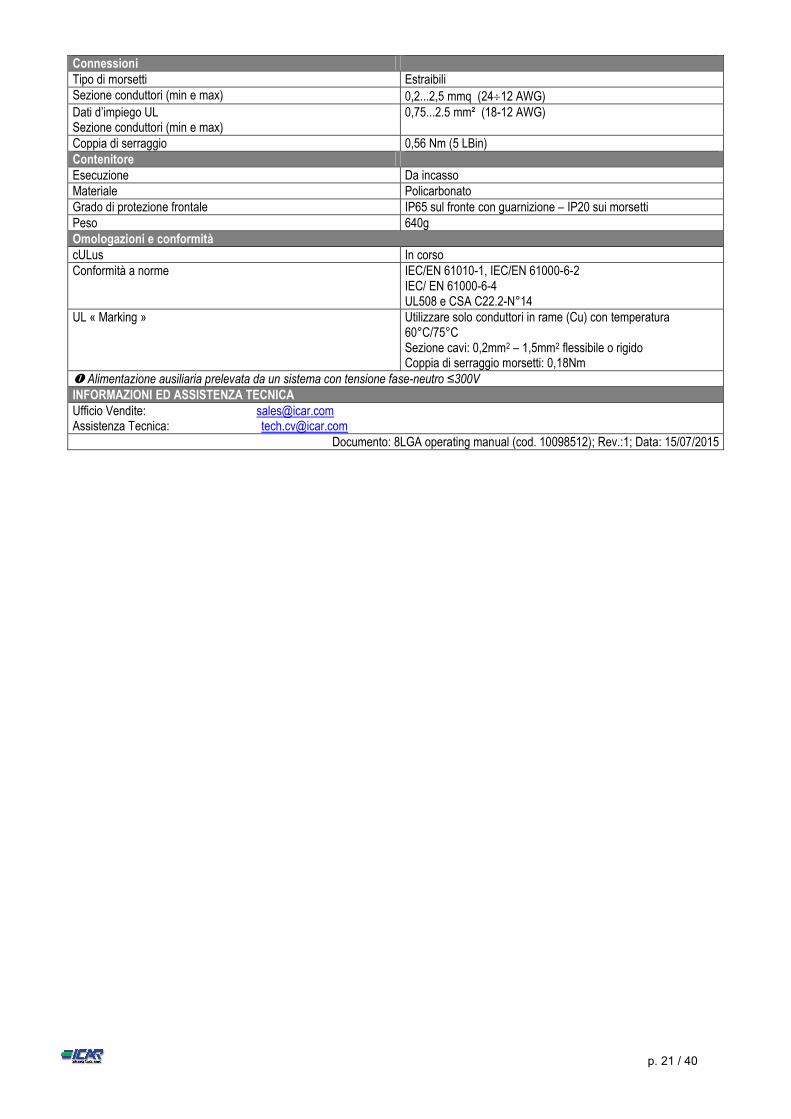
Connessioni Tipo di morsetti Estraibili Sezione conduttori (min e max) 0,2...2,5 mmq (2412 AWG) Dati d’impiego UL Sezione conduttori (min e max)
0,75...2.5 mm² (18-12 AWG)
Coppia di serraggio 0,56 Nm (5 LBin) Contenitore Esecuzione Da incasso Materiale Policarbonato Grado di protezione frontale IP65 sul fronte con guarnizione – IP20 sui morsetti Peso 640g Omologazioni e conformità cULus In corso Conformità a norme IEC/EN 61010-1, IEC/EN 61000-6-2
IEC/ EN 61000-6-4 UL508 e CSA C22.2-N°14
UL « Marking »
Utilizzare solo conduttori in rame (Cu) con temperatura 60°C/75°C Sezione cavi: 0,2mm2 – 1,5mm2 flessibile o rigido Coppia di serraggio morsetti: 0,18Nm
Alimentazione ausiliaria prelevata da un sistema con tensione fase-neutro ≤300V INFORMAZIONI ED ASSISTENZA TECNICA Ufficio Vendite: [email protected] Assistenza Tecnica: [email protected]
Documento: 8LGA operating manual (cod. 10098512); Rev.:1; Data: 15/07/2015
p. 22 / 40
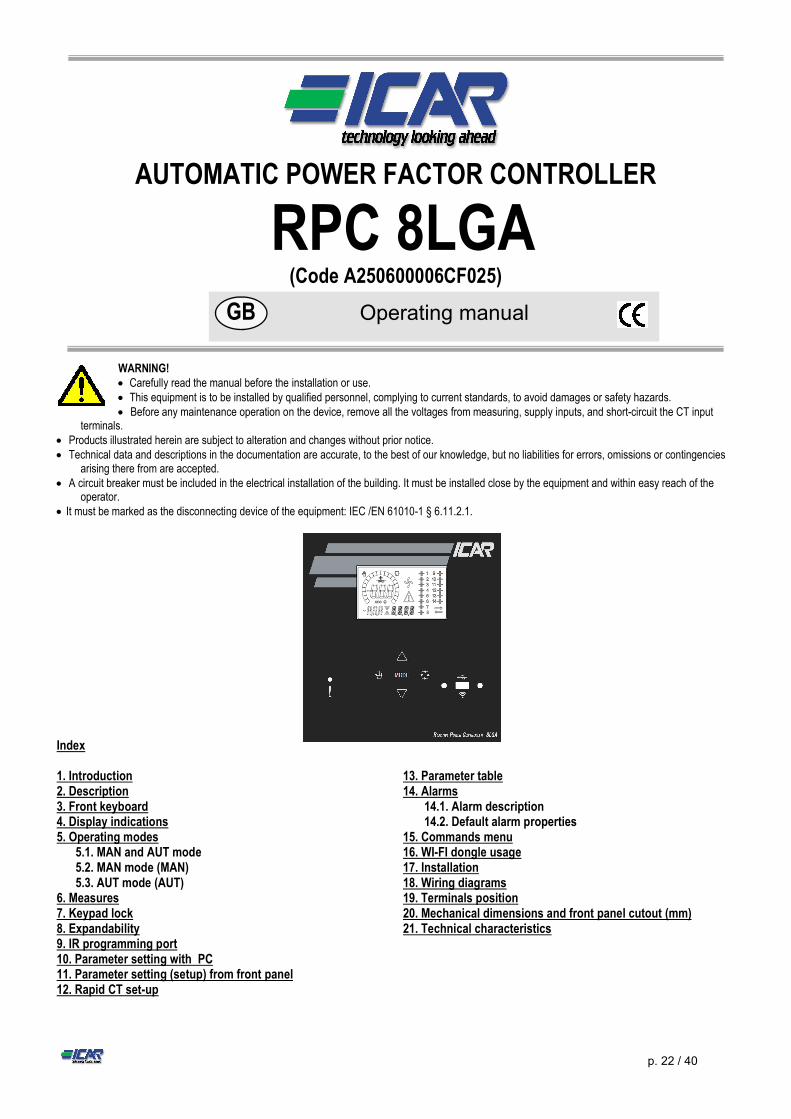
AUTOMATIC POWER FACTOR CONTROLLER
RPC 8LGA (Code A250600006CF025)
WARNING! Carefully read the manual before the installation or use. This equipment is to be installed by qualified personnel, complying to current standards, to avoid damages or safety hazards. Before any maintenance operation on the device, remove all the voltages from measuring, supply inputs, and short-circuit the CT input
terminals. Products illustrated herein are subject to alteration and changes without prior notice. Technical data and descriptions in the documentation are accurate, to the best of our knowledge, but no liabilities for errors, omissions or contingencies
arising there from are accepted. A circuit breaker must be included in the electrical installation of the building. It must be installed close by the equipment and within easy reach of the
operator. It must be marked as the disconnecting device of the equipment: IEC /EN 61010-1 § 6.11.2.1. Index 1. Introduction 2. Description 3. Front keyboard 4. Display indications 5. Operating modes
5.1. MAN and AUT mode 5.2. MAN mode (MAN) 5.3. AUT mode (AUT)
6. Measures 7. Keypad lock 8. Expandability 9. IR programming port 10. Parameter setting with PC 11. Parameter setting (setup) from front panel 12. Rapid CT set-up
13. Parameter table 14. Alarms
14.1. Alarm description 14.2. Default alarm properties
15. Commands menu 16. WI-FI dongle usage 17. Installation 18. Wiring diagrams 19. Terminals position 20. Mechanical dimensions and front panel cutout (mm) 21. Technical characteristics
GB Operating manual
p. 23 / 40
1. Introduction The RPC 8LGA automatic power factor regulator has been designed to offer state-of-the-art functions for power factor compensation applications. Built with dedicated components and extremely compact, the RPC 8LGA combines the modern design of the front panel with practical installation and the possibility of expansion from the rear, where one expansion module can be slotted. The LCD screen provides a clear and intuitive user interface. 2. Description Automatic power factor controller. Flush-mount, standard 144x144mm housing. Backlit LCD screen. Version:
o 8LGA with 8 relays, expandable to 14 max. 5 navigation keys for function and settings. Alarm messages in 6 languages. Expansion bus with 2 slot expansion modules:
o RS232, RS485, USB Ethernet communications interface. o Additional relay outputs.
High accuracy TRMS measurements. Wide selection of electrical measures, including voltage and current THD with harmonic analysis up to 15th order. Voltage input separated from power supply, suitable for VT connection in medium voltage applications. Wide-range power supply (100-440VAC). Front optical programming interface: galvanically isolated, high speed, waterproof, USB and WIFI dongle compatible. Programming from front panel or from PC. 2-level password protection for settings. Backup copy of original commissioning settings. Built-in temperature sensor. 3. Front keyboard Key - Used to select among available measurements. Used also to access programming menus. keys - Used to set values and to select steps. key - Used to select automatic operating mode. key - Used to select manual operating mode.
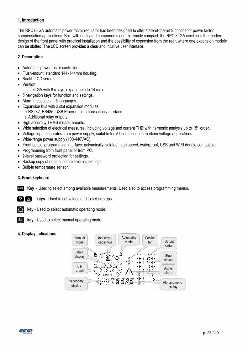
4. Display indications
MODE
▼ ▲
Output status
Cooling fan
Secondary display
Active alarm
Automatiic mode
Manual mode
Main display
Inductive / capacitive
Bar graph
Alphanumeric display
Step status
p. 24 / 40
5. Operating modes There are two possible operating modes, listed below: 5.1. MAN and AUT Modes The icons AUT and MAN indicate the operating mode automatic or manual. To change the mode, press and hold the or button for 1 sec. The operating mode remains stored even after removing and reapplying the power supply voltage.
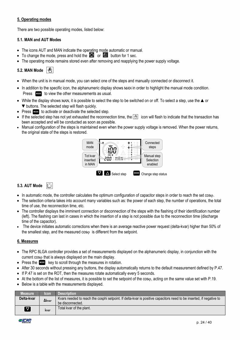
5.2. MAN Mode When the unit is in manual mode, you can select one of the steps and manually connected or disconnect it.
In addition to the specific icon, the alphanumeric display shows MAN in order to highlight the manual mode condition. Press to view the other measurements as usual.
While the display shows MAN, it is possible to select the step to be switched on or off. To select a step, use the ▲or ▼buttons. The selected step will flash quickly.
Press to activate or deactivate the selected step. If the selected step has not yet exhausted the reconnection time, the icon will flash to indicate that the transaction has
been accepted and will be conducted as soon as possible. Manual configuration of the steps is maintained even when the power supply voltage is removed. When the power returns,
the original state of the steps is restored.
Select step Change step status
5.3. AUT Mode
In automatic mode, the controller calculates the optimum configuration of capacitor steps in order to reach the set cos. The selection criteria takes into account many variables such as: the power of each step, the number of operations, the total
time of use, the reconnection time, etc. The controller displays the imminent connection or disconnection of the steps with the flashing of their identification number
(left). The flashing can last in cases in which the insertion of a step is not possible due to the reconnection time (discharge time of the capacitor).
The device initiates automatic corrections when there is an average reactive power request (delta-kvar) higher than 50% of the smallest step, and the measured cos is different from the setpoint.
6. Measures The RPC 8LGA controller provides a set of measurements displayed on the alphanumeric display, in conjunction with the
current cos that is always displayed on the main display. Press the key to scroll through the measures in rotation. After 30 seconds without pressing any buttons, the display automatically returns to the default measurement defined by P.47. If P.47 is set on the ROT, then the measures rotate automatically every 5 seconds. At the bottom of the list of measures, it is possible to set the setpoint of the cos, acting on the same value set with P.19. Below is a table with the measurements displayed.
Measure Icon Description Delta-kvar Δkvar Kvars needed to reach the cosphi setpoint. If delta-kvar is positive capacitors need to be inserted, if negative to
be disconnected.
kvar Total kvar of the plant.
MODE ▼ ▲
MODE
MODE
MODE
▼
Manual step Selection enabled
Connected steps
MAN mode
Tot kvar inserited in MAN
p. 25 / 40
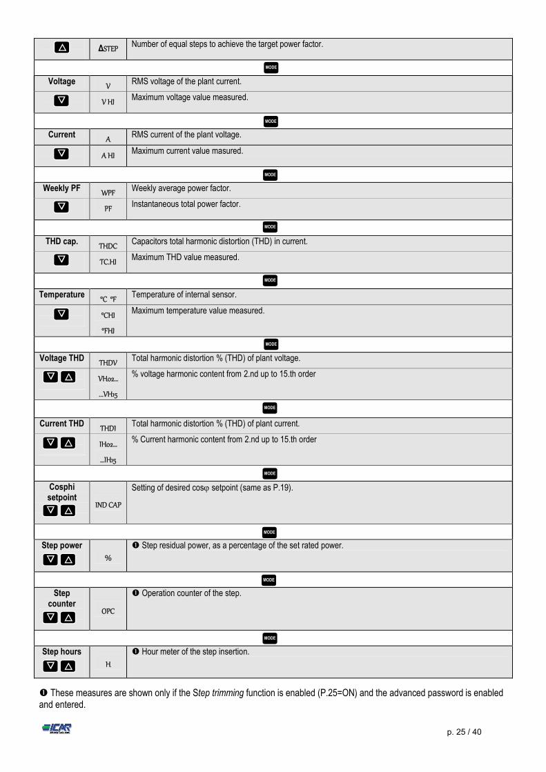
ΔSTEP Number of equal steps to achieve the target power factor.
Voltage V RMS voltage of the plant current.
V HI Maximum voltage value measured.
Current A RMS current of the plant voltage.
A HI Maximum current value masured.
Weekly PF WPF Weekly average power factor.
PF Instantaneous total power factor.
THD cap. THDC Capacitors total harmonic distortion (THD) in current.
TC.HI Maximum THD value measured.
Temperature °C °F Temperature of internal sensor.
°CHI
°FHI
Maximum temperature value measured.
Voltage THD THDV Total harmonic distortion % (THD) of plant voltage.
VH02…
...VH15
% voltage harmonic content from 2.nd up to 15.th order
Current THD THDI Total harmonic distortion % (THD) of plant current.
IH02…
…IH15
% Current harmonic content from 2.nd up to 15.th order
Cosphi setpoint
IND CAP
Setting of desired cos setpoint (same as P.19).
Step power
%
Step residual power, as a percentage of the set rated power.
Step counter
OPC
Operation counter of the step.
Step hours
H
Hour meter of the step insertion.
These measures are shown only if the Step trimming function is enabled (P.25=ON) and the advanced password is enabled and entered.
MODE
▲
▼
▼
▼
▼
▼
MODE
MODE
▼ ▲
MODE
MODE
MODE
▼ ▲
▼ ▲
▼ ▲
▼ ▲
▼ ▲
MODE
MODE
MODE
MODE
MODE
p. 26 / 40
7. Keypad lock A function to exclude all modification to operating parameters can be enabled; measurement viewing is still provided in any
case. To lock and unlock the keypad, press and keep key pressed. Then press the ▲ key three times and the ▼key twice
and after that release .
The display will show LOC when the keypad is locked and UNL when it is unlocked.
When the lock is enabled, it is not possible to make the following operations: o Operation between automatic and manual mode o Access to set-up menus o Change of cos set-point
By attempting to conduct the above operations, the display will view LOC to indicate the locked keypad state. 8. Expandability Thanks to expansion bus, the RPC 8LGA can be expanded with two expansion series module. The supported expansion modules can be grouped in the following categories: o additional steps o communication modules o digital I/O modules
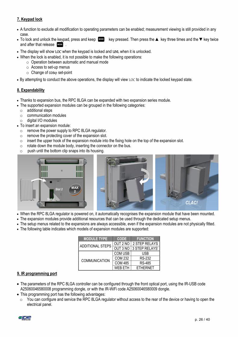
To insert an expansion module: o remove the power supply to RPC 8LGA regulator. o remove the protecting cover of the expansion slot. o insert the upper hook of the expansion module into the fixing hole on the top of the expansion slot. o rotate down the module body, inserting the connector on the bus. o push until the bottom clip snaps into its housing.
When the RPC 8LGA regulator is powered on, it automatically recognises the expansion module that have been mounted. The expansion modules provide additional resources that can be used through the dedicated setup menus. The setup menus related to the expansions are always accessible, even if the expansion modules are not physically fitted. The following table indicates which models of expansion modules are supported:
9. IR programming port The parameters of the RPC 8LGA controller can be configured through the front optical port, using the IR-USB code
A25060046580008 programming dongle, or with the IR-WiFi code A25060046580009 dongle. This programming port has the following advantages: o You can configure and service the RPC 8LGA regulator without access to the rear of the device or having to open the
electrical panel.
MODULE TYPE CODE FUNCTION
ADDITIONAL STEPS OUT 2 NO 2 STEP RELAYS OUT 3 NO 3 STEP RELAYS’
COMMUNICATION
COM USB USB COM 232 RS-232 COM 485 RS-485 WEB ETH ETHERNET
MODE
CLAC! Slot 1
Slot 2 MAX 2
MODE
p. 27 / 40
o It is galvanically isolated from the internal circuits of the RPC 8LGA regulator, guaranteeing the greatest safety for the operator.
o High speed data transfer. o IP54 front panel protection. o Limits the possibility of unauthorized access with device configuration since it is necessary to have the IR-USB or IR-WI-
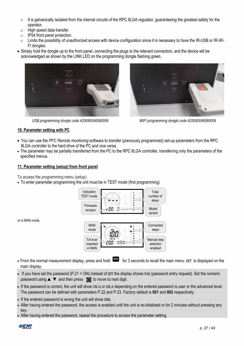
FI dongles. Simply hold the dongle up to the front panel, connecting the plugs to the relevant connectors, and the device will be
acknowledged as shown by the LINK LED on the programming dongle flashing green.
USB programming dongle code A25060046580008 WIFI programming dongle code A25060046580009
10. Parameter setting with PC You can use the PFC Remote monitoring software to transfer (previously programmed) set-up parameters from the RPC
8LGA controller to the hard drive of the PC and vice versa. The parameter may be partially transferred from the PC to the RPC 8LGA controller, transferring only the parameters of the
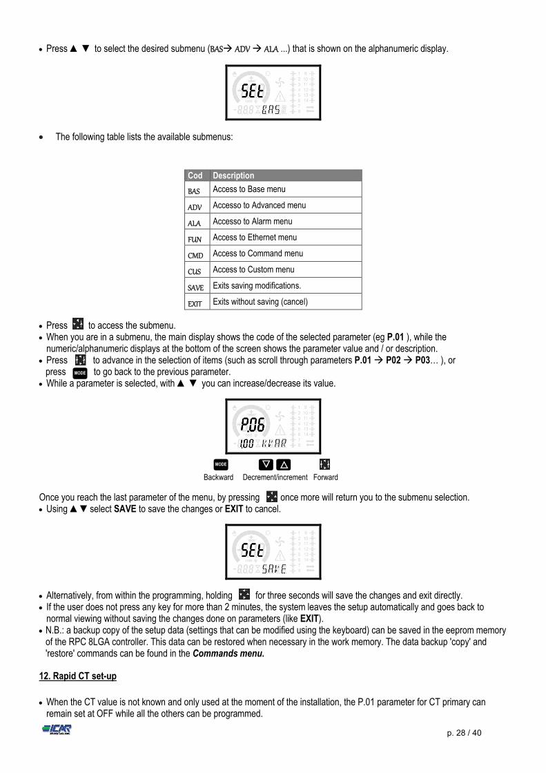
specified menus. 11. Parameter setting (setup) from front panel To access the programming menu (setup): To enter parameter programming the unit must be in TEST mode (first programming)
or in MAN mode.
From the normal measurement display, press and hold for 3 seconds to recall the main menu. SET is displayed on the main display.
If you have set the password (P.21 = ON) instead of SET the display shows PAS (password entry request). Set the numeric
password using ▲ ▼ and then press to move to next digit.
If the password is correct, the unit will show OK U or OK A depending on the entered password is user or the advanced level. The password can be defined with parameters P.22 and P.23. Factory default is 001 and 002 respectively.
If the entered password is wrong the unit will show ERR.
After having entered the password, the access is enabled until the unit is re-initialized or for 2 minutes without pressing any key.
After having entered the password, repeat the procedure to access the parameter setting.
MODE
Indication TEST mode
Total number of
steps
Firmware revision Model
variant
MAN mode
Connected steps
Tot kvar inserited in MAN
Manual step selection enabled
p. 28 / 40
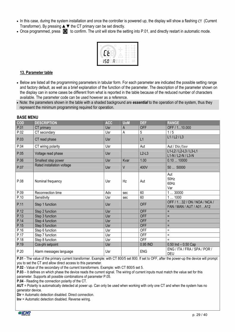
Press ▲ ▼ to select the desired submenu (BAS ADV ALA ...) that is shown on the alphanumeric display.
The following table lists the available submenus:
Cod Description
BAS Access to Base menu
ADV Accesso to Advanced menu
ALA Accesso to Alarm menu
FUN Access to Ethernet menu
CMD Access to Command menu
CUS Access to Custom menu
SAVE Exits saving modifications.
EXIT Exits without saving (cancel)
Press to access the submenu. When you are in a submenu, the main display shows the code of the selected parameter (eg P.01 ), while the
numeric/alphanumeric displays at the bottom of the screen shows the parameter value and / or description. Press to advance in the selection of items (such as scroll through parameters P.01 P02 P03… ), or
press to go back to the previous parameter. While a parameter is selected, with ▲ ▼ you can increase/decrease its value.
Backward Decrement/increment Forward
Once you reach the last parameter of the menu, by pressing once more will return you to the submenu selection. Using ▲▼select SAVE to save the changes or EXIT to cancel.
Alternatively, from within the programming, holding for three seconds will save the changes and exit directly. If the user does not press any key for more than 2 minutes, the system leaves the setup automatically and goes back to
normal viewing without saving the changes done on parameters (like EXIT). N.B.: a backup copy of the setup data (settings that can be modified using the keyboard) can be saved in the eeprom memory
of the RPC 8LGA controller. This data can be restored when necessary in the work memory. The data backup 'copy' and 'restore' commands can be found in the Commands menu.
12. Rapid CT set-up
When the CT value is not known and only used at the moment of the installation, the P.01 parameter for CT primary can
remain set at OFF while all the others can be programmed.
MODE ▼ ▲
MODE
p. 29 / 40
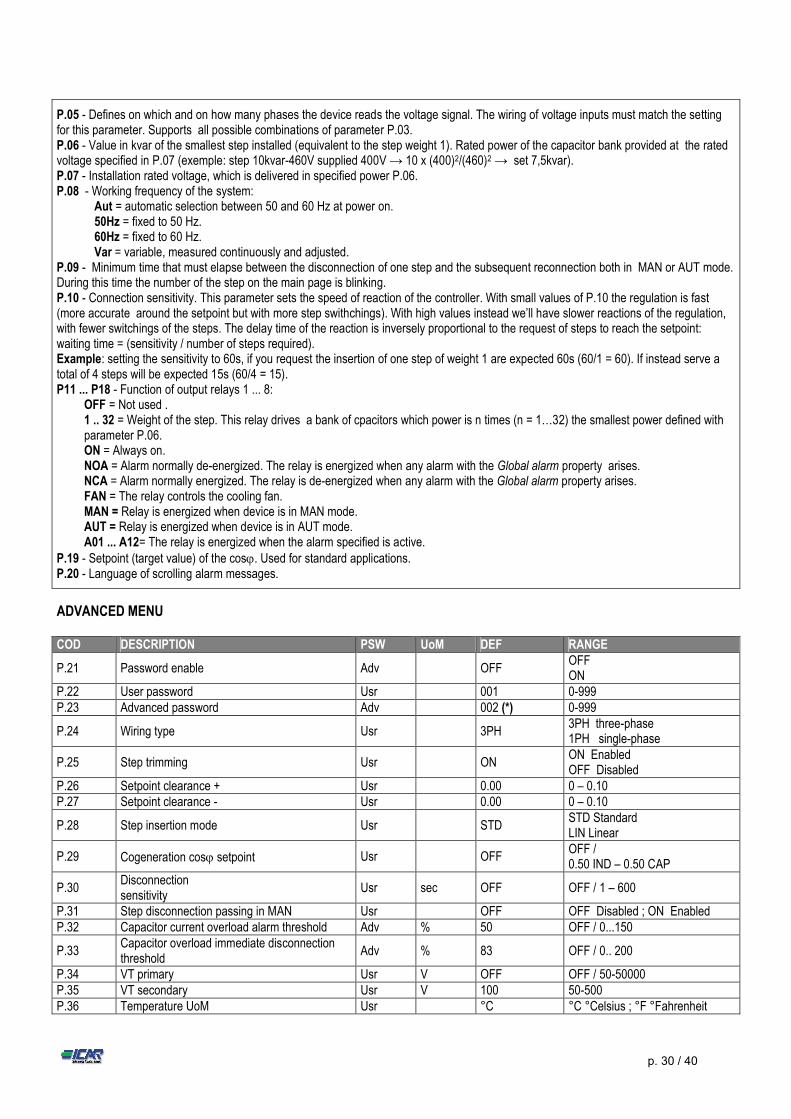
In this case, during the system installation and once the controller is powered up, the display will show a flashing CT (Current Transformer). By pressing ▲▼the CT primary can be set directly.
Once programmed, press to confirm. The unit will store the setting into P.01, and directly restart in automatic mode.
13. Parameter table
Below are listed all the programming parameters in tabular form. For each parameter are indicated the possible setting range and factory default, as well as a brief explanation of the function of the parameter. The description of the parameter shown on the display can in some cases be different from what is reported in the table because of the reduced number of characters available. The parameter code can be used however as a reference.
Note: the parameters shown in the table with a shaded background are essential to the operation of the system, thus they represent the minimum programming required for operation.
BASE MENU
COD DESCRIPTION ACC UoM DEF RANGE P.01 CT primary Usr A OFF OFF / 1...10.000 P.02 CT secondary Usr A 5 1 / 5
P.03 CT read phase Usr L1 L1 / L2 / L3
P.04 CT wiring polarity Usr Aut Aut / Dir/Inv
P.05 Voltage read phase Usr L2-L3 L1-L2 / L2-L3 / L3-L1 L1-N / L2-N / L3-N
P.06 Smallest step power Usr Kvar 1.00 0.10 ... 10000
P.07 Rated installation voltage
Usr V 400V 50 ... 50000
P.08 Nominal frequency Usr Hz Aut
Aut 50Hz 60Hz Var
P.09 Reconnection time Adv sec 60 1 … 30000 P.10 Sensitivity Usr sec 60 1 … 1000
P.11 Step 1 function Usr OFF OFF / 1…32 / ON / NOA / NCA / FAN / MAN / AUT / A01…A12
P.12 Step 2 function Usr OFF = P.13 Step 3 function Usr OFF = P.14 Step 4 function Usr OFF = P.15 Step 5 function Usr OFF = P.16 Step 6 function Usr OFF = P.17 Step 7 function Usr OFF = P.18 Step 8 function Usr OFF = P.19 Cos-phi setpoint Usr 0.95 IND 0.50 Ind – 0.50 Cap
P.20 Alarm messages language Usr ENG ENG / ITA / FRA / SPA / POR / DEU
P.01 - The value of the primary current transformer. Example: with CT 800/5 set 800. If set to OFF, after the power-up the device will prompt you to set the CT and allow direct access to this parameter. P.02 - Value of the secondary of the current transformers. Example: with CT 800/5 set 5. P.03 – It defines on which phase the device reads the current signal. The wiring of current inputs must match the value set for this parameter. Supports all possible combinations of parameter P.05. P.04 - Reading the connection polarity of the CT. AUT = Polarity is automatically detected at power up. Can only be used when working with only one CT and when the system has no generator device. Dir = Automatic detection disabled. Direct connection. Inv = Automatic detection disabled. Reverse wiring.
p. 30 / 40
ADVANCED MENU
P.05 - Defines on which and on how many phases the device reads the voltage signal. The wiring of voltage inputs must match the setting for this parameter. Supports all possible combinations of parameter P.03. P.06 - Value in kvar of the smallest step installed (equivalent to the step weight 1). Rated power of the capacitor bank provided at the rated voltage specified in P.07 (exemple: step 10kvar-460V supplied 400V → 10 x (400)2/(460)2 → set 7,5kvar). P.07 - Installation rated voltage, which is delivered in specified power P.06. P.08 - Working frequency of the system:
Aut = automatic selection between 50 and 60 Hz at power on. 50Hz = fixed to 50 Hz. 60Hz = fixed to 60 Hz. Var = variable, measured continuously and adjusted.
P.09 - Minimum time that must elapse between the disconnection of one step and the subsequent reconnection both in MAN or AUT mode. During this time the number of the step on the main page is blinking. P.10 - Connection sensitivity. This parameter sets the speed of reaction of the controller. With small values of P.10 the regulation is fast (more accurate around the setpoint but with more step swithchings). With high values instead we’ll have slower reactions of the regulation, with fewer switchings of the steps. The delay time of the reaction is inversely proportional to the request of steps to reach the setpoint: waiting time = (sensitivity / number of steps required). Example: setting the sensitivity to 60s, if you request the insertion of one step of weight 1 are expected 60s (60/1 = 60). If instead serve a total of 4 steps will be expected 15s (60/4 = 15). P11 ... P18 - Function of output relays 1 ... 8:
OFF = Not used . 1 .. 32 = Weight of the step. This relay drives a bank of cpacitors which power is n times (n = 1…32) the smallest power defined with parameter P.06. ON = Always on. NOA = Alarm normally de-energized. The relay is energized when any alarm with the Global alarm property arises. NCA = Alarm normally energized. The relay is de-energized when any alarm with the Global alarm property arises. FAN = The relay controls the cooling fan. MAN = Relay is energized when device is in MAN mode. AUT = Relay is energized when device is in AUT mode. A01 ... A12= The relay is energized when the alarm specified is active.
P.19 - Setpoint (target value) of the cos. Used for standard applications. P.20 - Language of scrolling alarm messages.
COD DESCRIPTION PSW UoM DEF RANGE
P.21 Password enable Adv OFF OFF ON
P.22 User password Usr 001 0-999 P.23 Advanced password Adv 002 (*) 0-999
P.24 Wiring type Usr 3PH 3PH three-phase 1PH single-phase
P.25 Step trimming Usr ON ON Enabled OFF Disabled
P.26 Setpoint clearance + Usr 0.00 0 – 0.10 P.27 Setpoint clearance - Usr 0.00 0 – 0.10
P.28 Step insertion mode Usr STD STD Standard LIN Linear
P.29 Cogeneration cos setpoint Usr OFF OFF / 0.50 IND – 0.50 CAP
P.30 Disconnection sensitivity
Usr sec OFF OFF / 1 – 600
P.31 Step disconnection passing in MAN Usr OFF OFF Disabled ; ON Enabled P.32 Capacitor current overload alarm threshold Adv % 50 OFF / 0...150
P.33 Capacitor overload immediate disconnection threshold
Adv % 83 OFF / 0.. 200
P.34 VT primary Usr V OFF OFF / 50-50000 P.35 VT secondary Usr V 100 50-500 P.36 Temperature UoM Usr °C °C °Celsius ; °F °Fahrenheit
p. 31 / 40
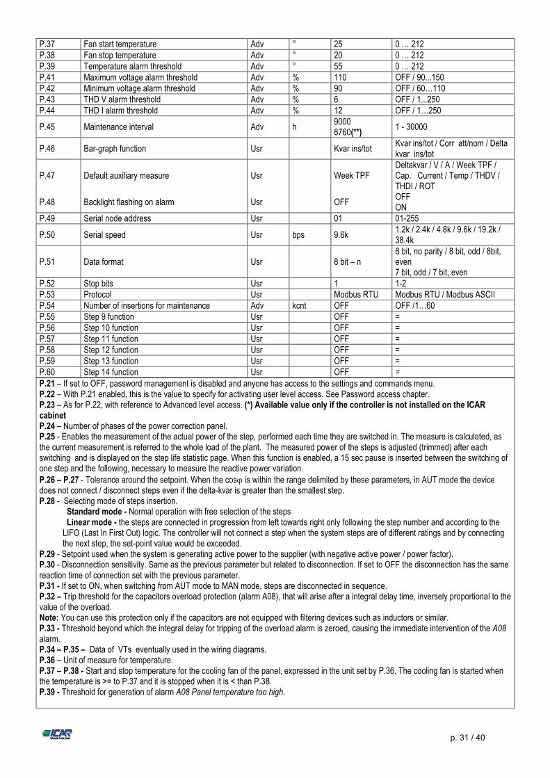
P.37 Fan start temperature Adv ° 25 0 … 212 P.38 Fan stop temperature Adv ° 20 0 … 212 P.39 Temperature alarm threshold Adv ° 55 0 … 212 P.41 Maximum voltage alarm threshold Adv % 110 OFF / 90...150 P.42 Minimum voltage alarm threshold Adv % 90 OFF / 60…110 P.43 THD V alarm threshold Adv % 6 OFF / 1...250 P.44 THD I alarm threshold Adv % 12 OFF / 1…250
P.45 Maintenance interval Adv h 9000 8760(**)
1 - 30000
P.46 Bar-graph function Usr Kvar ins/tot Kvar ins/tot / Corr att/nom / Delta kvar ins/tot
P.47 Default auxiliary measure Usr Week TPF Deltakvar / V / A / Week TPF / Cap. Current / Temp / THDV / THDI / ROT
P.48 Backlight flashing on alarm Usr OFF OFF ON
P.49 Serial node address Usr 01 01-255
P.50 Serial speed Usr bps 9.6k 1.2k / 2.4k / 4.8k / 9.6k / 19.2k / 38.4k
P.51 Data format Usr 8 bit – n 8 bit, no parity / 8 bit, odd / 8bit, even 7 bit, odd / 7 bit, even
P.52 Stop bits Usr 1 1-2 P.53 Protocol Usr Modbus RTU Modbus RTU / Modbus ASCII P.54 Number of insertions for maintenance Adv kcnt OFF OFF /1…60 P.55 Step 9 function Usr OFF = P.56 Step 10 function Usr OFF = P.57 Step 11 function Usr OFF = P.58 Step 12 function Usr OFF = P.59 Step 13 function Usr OFF = P.60 Step 14 function Usr OFF = P.21 – If set to OFF, password management is disabled and anyone has access to the settings and commands menu. P.22 – With P.21 enabled, this is the value to specify for activating user level access. See Password access chapter. P.23 – As for P.22, with reference to Advanced level access. (*) Available value only if the controller is not installed on the ICAR cabinet P.24 – Number of phases of the power correction panel. P.25 - Enables the measurement of the actual power of the step, performed each time they are switched in. The measure is calculated, as the current measurement is referred to the whole load of the plant. The measured power of the steps is adjusted (trimmed) after each switching and is displayed on the step life statistic page. When this function is enabled, a 15 sec pause is inserted between the switching of one step and the following, necessary to measure the reactive power variation. P.26 – P.27 - Tolerance around the setpoint. When the cos is within the range delimited by these parameters, in AUT mode the device does not connect / disconnect steps even if the delta-kvar is greater than the smallest step. P.28 - Selecting mode of steps insertion. Standard mode - Normal operation with free selection of the steps Linear mode - the steps are connected in progression from left towards right only following the step number and according to the
LIFO (Last In First Out) logic. The controller will not connect a step when the system steps are of different ratings and by connecting the next step, the set-point value would be exceeded.
P.29 - Setpoint used when the system is generating active power to the supplier (with negative active power / power factor). P.30 - Disconnection sensitivity. Same as the previous parameter but related to disconnection. If set to OFF the disconnection has the same reaction time of connection set with the previous parameter. P.31 - If set to ON, when switching from AUT mode to MAN mode, steps are disconnected in sequence. P.32 – Trip threshold for the capacitors overload protection (alarm A08), that will arise after a integral delay time, inversely proportional to the value of the overload. Note: You can use this protection only if the capacitors are not equipped with filtering devices such as inductors or similar. P.33 - Threshold beyond which the integral delay for tripping of the overload alarm is zeroed, causing the immediate intervention of the A08 alarm. P.34 – P.35 – Data of VTs eventually used in the wiring diagrams. P.36 – Unit of measure for temperature. P.37 – P.38 - Start and stop temperature for the cooling fan of the panel, expressed in the unit set by P.36. The cooling fan is started when the temperature is >= to P.37 and it is stopped when it is < than P.38. P.39 - Threshold for generation of alarm A08 Panel temperature too high.
p. 32 / 40
ALARM MENU
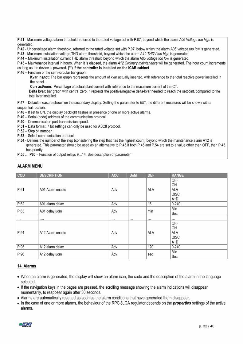
COD DESCRIPTION ACC UoM DEF RANGE
P.61 A01 Alarm enable Adv ALA
OFF ON ALA DISC A+D
P.62 A01 alarm delay Adv 15 0-240
P.63 A01 delay uom Adv min Min Sec
… …. … … … …
P.94 A12 Alarm enable Adv ALA
OFF ON ALA DISC A+D
P.95 A12 alarm delay Adv 120 0-240
P.96 A12 delay uom Adv sec Min Sec
14. Alarms When an alarm is generated, the display will show an alarm icon, the code and the description of the alarm in the language
selected. If the navigation keys in the pages are pressed, the scrolling message showing the alarm indications will disappear
momentarily, to reappear again after 30 seconds. Alarms are automatically resetted as soon as the alarm conditions that have generated them disappear. In the case of one or more alarms, the behaviour of the RPC 8LGA regulator depends on the properties settings of the active
alarms.
P.41 - Maximum voltage alarm threshold, referred to the rated voltage set with P.07, beyond which the alarm A06 Voltage too high is generated. P.42 - Undervoltage alarm threshold, referred to the rated voltage set with P.07, below which the alarm A05 voltage too low is generated. P.43 - Maximum installation voltage THD alarm threshold, beyond which the alarm A10 THDV too high is generated. P.44 – Maximum installation current THD alarm threshold beyond which the alarm A05 voltage too low is generated. P.45 – Maintenance interval in hours. When it is elapsed, the alarm A12 Ordinary maintenance will be generated. The hour count increments as long as the device is powered. (**) If the controller is installed on the ICAR cabinet P.46 – Function of the semi-circular bar-graph.
Kvar ins/tot: The bar graph represents the amount of kvar actually inserted, with reference to the total reactive power installed in the panel. Curr act/nom: Percentage of actual plant current with reference to the maximum current of the CT.
Delta kvar: bar graph with central zero. It represts the positive/negative delta-kvar needed to reach the setpoint, compared to the total kvar installed.
P.47 – Default measure shown on the secondary display. Setting the parameter to ROT, the different measures will be shown with a sequential rotation. P.48 – If set to ON, the display backlight flashes in presence of one or more active alarms. P.49 – Serial (node) address of the communication protocol. P.50 – Communication port transmission speed. P.51 – Data format. 7 bit settings can only be used for ASCII protocol. P.52 – Stop bit number. P.53 – Select communication protocol. P.54 - Defines the number of the step (considering the step that has the highest count) beyond which the maintenance alarm A12 is
generated. This parameter should be used as an alternative to P.45.If both P.45 and P.54 are set to a value other than OFF, then P.45 has priority.
P.55 … P60 – Function of output relays 9…14. See description of parameter
p. 33 / 40
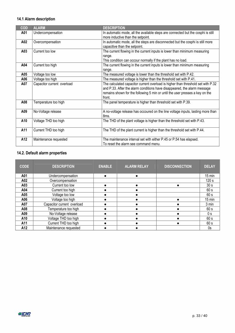
14.1 Alarm description
COD ALARM DESCRIPTION A01 Undercompensation In automatic mode, all the available steps are connected but the cosphi is still
more inductive than the setpoint. A02 Overcompensation In automatic mode, all the steps are disconnected but the cosphi is still more
capacitive than the setpoint. A03 Current too low The current flowing in the current inputs is lower than minimum measuring
range. This condition can occour normally if the plant has no load.
A04 Current too high The current flowing in the current inputs is lower than minimum measuring range.
A05 Voltage too low The measured voltage is lower than the threshold set with P.42. A06 Voltage too high The measured voltage is higher than the threshold set with P.41. A07 Capacitor current overload The calculated capacitor current overload is higher than threshold set with P.32
and P.33. After the alarm conditions have disappeared, the alarm message remains shown for the following 5 min or until the user presses a key on the front.
A08 Temperature too high The panel temperature is higher than threshold set with P.39.
A09 No-Voltage release A no-voltage release has occoured on the line voltage inputs, lasting more than 8ms.
A10 Voltage THD too high
The THD of the plant voltage is higher than the threshold set with P.43.
A11 Current THD too high The THD of the plant current is higher than the threshold set with P.44.
A12 Maintenance requested The maintenance interval set with either P.45 or P.54 has elapsed. To reset the alarm see command menu.
14.2. Default alarm properties
CODE
DESCRIPTION
ENABLE ALARM RELAY DISCONNECTION DELAY
A01 Undercompensation ● ● 15 min A02 Overcompensation 120 s A03 Current too low ● ● ● 30 s A04 Current too high ● ● 60 s A05 Voltage too low ● ● 60 s A06 Voltage too high ● ● ● 15 min A07 Capacitor current overload ● ● ● 3 min A08 Temperature too high ● ● ● 60 s A09 No-Voltage release ● ● ● 0 s A10 Voltage THD too high ● ● ● 60 s A11 Current THD too high ● ● ● 60 s A12 Maintenance requested ● ● 0s
p. 34 / 40
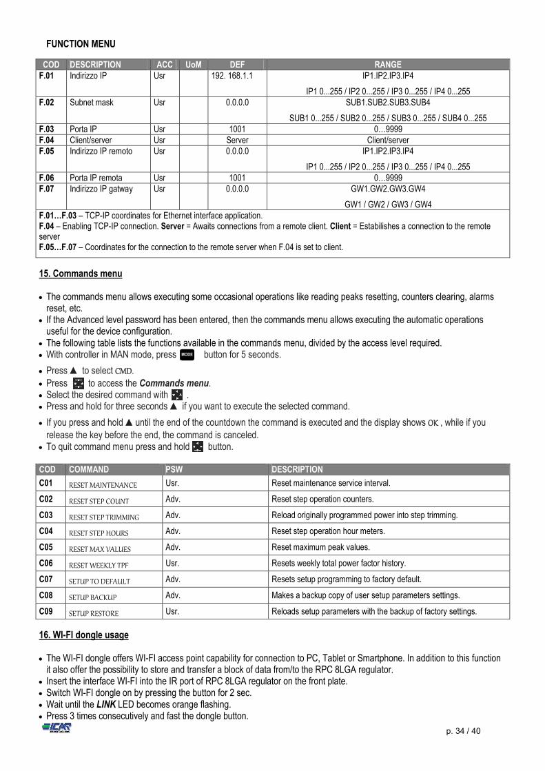
FUNCTION MENU
COD DESCRIPTION ACC UoM DEF RANGE F.01 Indirizzo IP Usr 192. 168.1.1 IP1.IP2.IP3.IP4
IP1 0...255 / IP2 0...255 / IP3 0...255 / IP4 0...255 F.02 Subnet mask Usr 0.0.0.0 SUB1.SUB2.SUB3.SUB4
SUB1 0...255 / SUB2 0...255 / SUB3 0...255 / SUB4 0...255 F.03 Porta IP Usr 1001 0…9999 F.04 Client/server Usr Server Client/server F.05 Indirizzo IP remoto Usr 0.0.0.0 IP1.IP2.IP3.IP4
IP1 0...255 / IP2 0...255 / IP3 0...255 / IP4 0...255 F.06 Porta IP remota Usr 1001 0…9999 F.07 Indirizzo IP gatway Usr 0.0.0.0 GW1.GW2.GW3.GW4
GW1 / GW2 / GW3 / GW4 F.01…F.03 – TCP-IP coordinates for Ethernet interface application. F.04 – Enabling TCP-IP connection. Server = Awaits connections from a remote client. Client = Estabilishes a connection to the remote server F.05…F.07 – Coordinates for the connection to the remote server when F.04 is set to client.
15. Commands menu The commands menu allows executing some occasional operations like reading peaks resetting, counters clearing, alarms
reset, etc. If the Advanced level password has been entered, then the commands menu allows executing the automatic operations
useful for the device configuration. The following table lists the functions available in the commands menu, divided by the access level required. With controller in MAN mode, press button for 5 seconds.
Press ▲ to select CMD.
Press to access the Commands menu. Select the desired command with . Press and hold for three seconds ▲ if you want to execute the selected command.
If you press and hold ▲until the end of the countdown the command is executed and the display shows OK , while if you release the key before the end, the command is canceled.
To quit command menu press and hold button. COD COMMAND PSW DESCRIPTION
C01 RESET MAINTENANCE Usr. Reset maintenance service interval.
C02 RESET STEP COUNT Adv. Reset step operation counters.
C03 RESET STEP TRIMMING Adv. Reload originally programmed power into step trimming.
C04 RESET STEP HOURS Adv. Reset step operation hour meters.
C05 RESET MAX VALUES Adv. Reset maximum peak values.
C06 RESET WEEKLY TPF Usr. Resets weekly total power factor history.
C07 SETUP TO DEFAULT Adv. Resets setup programming to factory default.
C08 SETUP BACKUP Adv. Makes a backup copy of user setup parameters settings.
C09 SETUP RESTORE Usr. Reloads setup parameters with the backup of factory settings.
16. WI-FI dongle usage The WI-FI dongle offers WI-FI access point capability for connection to PC, Tablet or Smartphone. In addition to this function
it also offer the possibility to store and transfer a block of data from/to the RPC 8LGA regulator. Insert the interface WI-FI into the IR port of RPC 8LGA regulator on the front plate. Switch WI-FI dongle on by pressing the button for 2 sec. Wait until the LINK LED becomes orange flashing. Press 3 times consecutively and fast the dongle button.
MODE
p. 35 / 40
At this point the display of the RPC 8LGA regulator shows the first of the 6 possible commands (D1…D6). Press ▲▼to select the desired command.
Press to execute the selected command. The unit will prompt for a confirmation (OK?). Press once again to confirm
or to cancel. The following table lists the possible commands:
COD COMMAND DESCRIPTION
D1 SETUP DEVICE CX02 Copies Setup settings from RPC 8LGA controller to WI-FI dongle.
D2 SETUP CX02 DEVICE Copies Setup settings from WI-FI dongle to RPC 8LGA controller.
D3 CLONE DEVICE CX02 Copies Setup settings and working data from RPC 8LGA controller to WI-FI dongle.
D4 CLONE CX02 DEVICE Copies Setup settings and working data from WI-FI dongle to RPC 8LGA controller.
D5 INFO DATA CX02 Shows information about data stored into WI-FI dongle.
D6 EXIT Exits from dongle menu.
For additional details, see WI-FI dongle operating manual.
17. Installation
8LGA controller is designed for flush-mount installation. With proper mounting, it guarantees IP54 front protection. Insert the device into the panel hole, making sure that the gasket is properly positioned between the panel and the device
front frame. From inside the panel, for each four of the fixing clips, position the clip in its square hole on the housing side,then move it
backwards in order to position the hook.
Repeat the same operation for the four clips. Tighten the fixing screw with a maximum torque of 0,5Nm. In case it is necessary to dismount the system, repeat the steps in opposite order. For the electrical connection see the wiring diagrams in the dedicated chapter and the requirements reported in the
technical characteristics table.
MODE
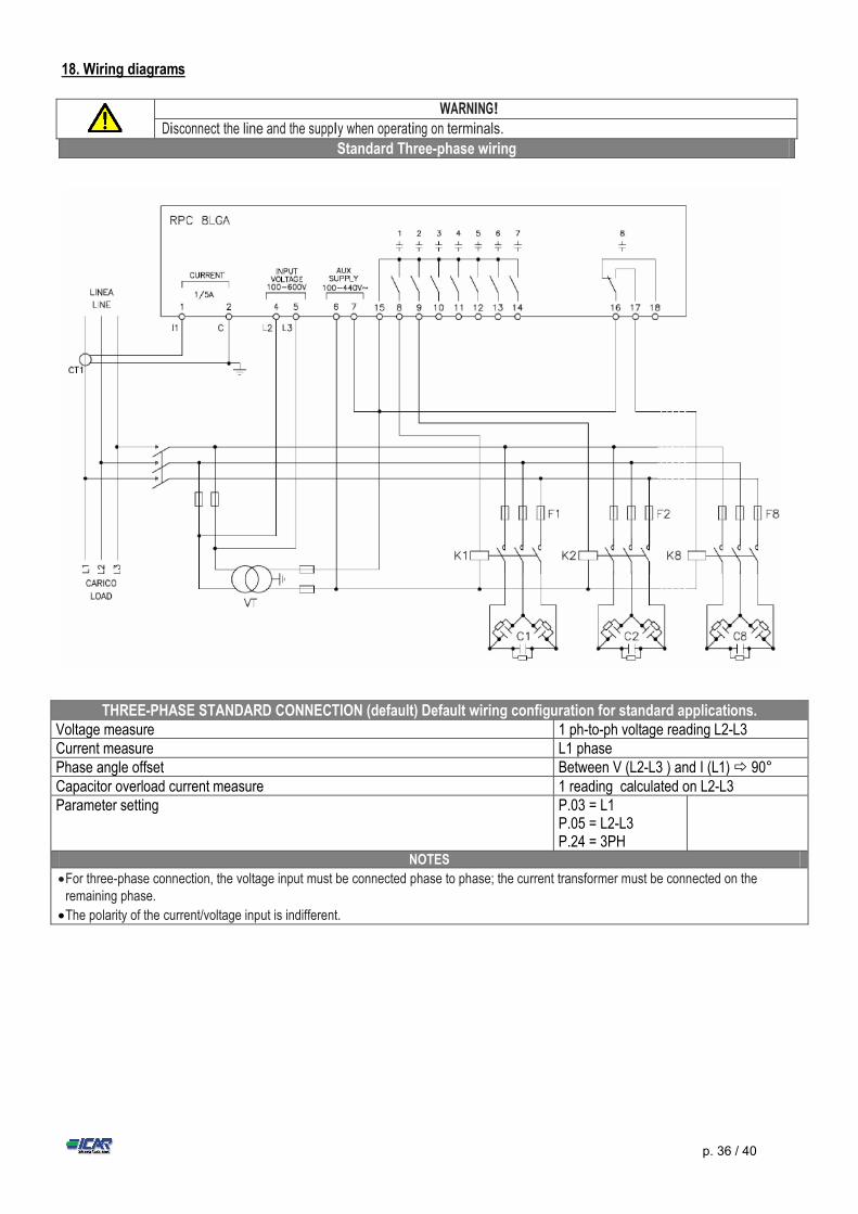
p. 36 / 40
18. Wiring diagrams
THREE-PHASE STANDARD CONNECTION (default) Default wiring configuration for standard applications. Voltage measure 1 ph-to-ph voltage reading L2-L3 Current measure L1 phase Phase angle offset Between V (L2-L3 ) and I (L1) 90° Capacitor overload current measure 1 reading calculated on L2-L3 Parameter setting P.03 = L1
P.05 = L2-L3 P.24 = 3PH
NOTES
For three-phase connection, the voltage input must be connected phase to phase; the current transformer must be connected on the remaining phase.
The polarity of the current/voltage input is indifferent.
WARNING! Disconnect the line and the supply when operating on terminals.
Standard Three-phase wiring
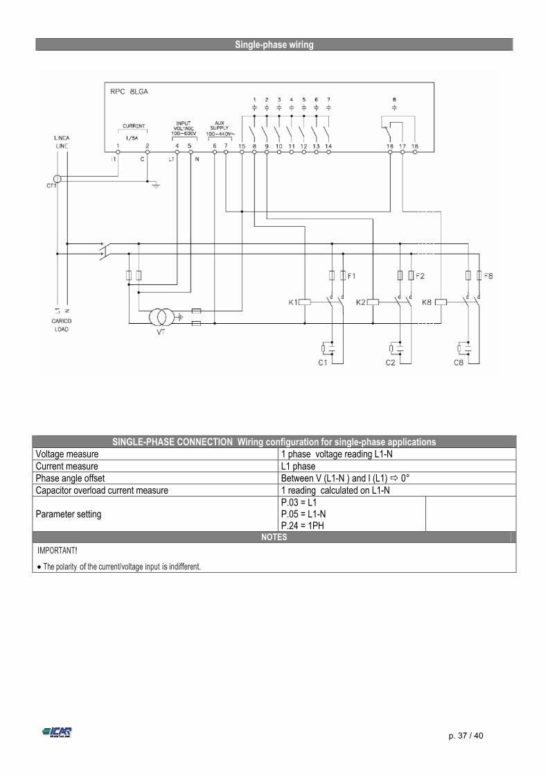
p. 37 / 40
Single-phase wiring
SINGLE-PHASE CONNECTION Wiring configuration for single-phase applications Voltage measure 1 phase voltage reading L1-N Current measure L1 phase Phase angle offset Between V (L1-N ) and I (L1) 0° Capacitor overload current measure 1 reading calculated on L1-N
Parameter setting P.03 = L1 P.05 = L1-N P.24 = 1PH
NOTES
IMPORTANT!
The polarity of the current/voltage input is indifferent.
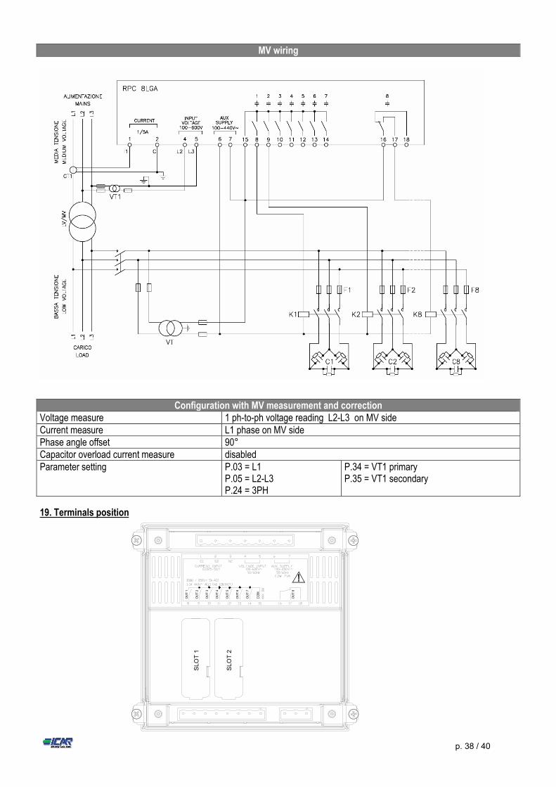
p. 38 / 40
Configuration with MV measurement and correction Voltage measure 1 ph-to-ph voltage reading L2-L3 on MV side Current measure L1 phase on MV side Phase angle offset 90° Capacitor overload current measure disabled Parameter setting P.03 = L1
P.05 = L2-L3 P.24 = 3PH
P.34 = VT1 primary P.35 = VT1 secondary
19. Terminals position
SL
OT
1
SL
OT
2
OU
T 1
OU
T 2
OU
T 3
OU
T 4
OU
T 5
OU
T 6
OU
T 7
OU
T 8
CO
M
MV wiring
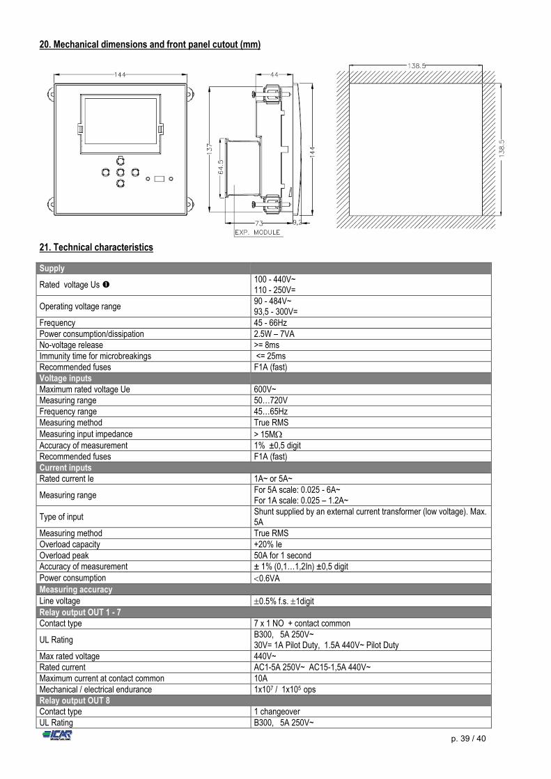
p. 39 / 40
20. Mechanical dimensions and front panel cutout (mm)
21. Technical characteristics
Supply
Rated voltage Us 100 - 440V~ 110 - 250V=
Operating voltage range 90 - 484V~ 93,5 - 300V=
Frequency 45 - 66Hz Power consumption/dissipation 2.5W – 7VA No-voltage release >= 8ms Immunity time for microbreakings <= 25ms Recommended fuses F1A (fast) Voltage inputs Maximum rated voltage Ue 600V~ Measuring range 50…720V Frequency range 45…65Hz Measuring method True RMS Measuring input impedance > 15M Accuracy of measurement 1% ±0,5 digit Recommended fuses F1A (fast) Current inputs Rated current Ie 1A~ or 5A~
Measuring range For 5A scale: 0.025 - 6A~ For 1A scale: 0.025 – 1.2A~
Type of input Shunt supplied by an external current transformer (low voltage). Max. 5A
Measuring method True RMS Overload capacity +20% Ie Overload peak 50A for 1 second Accuracy of measurement ± 1% (0,1…1,2In) ±0,5 digit Power consumption 0.6VA Measuring accuracy Line voltage 0.5% f.s. 1digit Relay output OUT 1 - 7 Contact type 7 x 1 NO + contact common
UL Rating B300, 5A 250V~ 30V= 1A Pilot Duty, 1.5A 440V~ Pilot Duty
Max rated voltage 440V~ Rated current AC1-5A 250V~ AC15-1,5A 440V~ Maximum current at contact common 10A Mechanical / electrical endurance 1x10⁷ / 1x10⁵ ops Relay output OUT 8 Contact type 1 changeover UL Rating B300, 5A 250V~
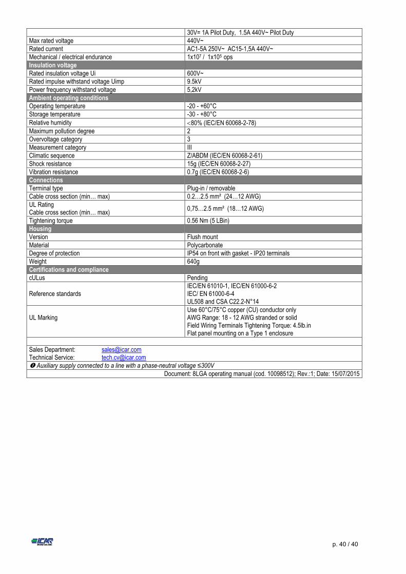
p. 40 / 40
30V= 1A Pilot Duty, 1.5A 440V~ Pilot Duty Max rated voltage 440V~ Rated current AC1-5A 250V~ AC15-1,5A 440V~ Mechanical / electrical endurance 1x10⁷ / 1x10⁵ ops Insulation voltage Rated insulation voltage Ui 600V~ Rated impulse withstand voltage Uimp 9.5kV Power frequency withstand voltage 5,2kV Ambient operating conditions Operating temperature -20 - +60°C Storage temperature -30 - +80°C Relative humidity 80% (IEC/EN 60068-2-78) Maximum pollution degree 2 Overvoltage category 3 Measurement category III Climatic sequence Z/ABDM (IEC/EN 60068-2-61) Shock resistance 15g (IEC/EN 60068-2-27) Vibration resistance 0.7g (IEC/EN 60068-2-6) Connections Terminal type Plug-in / removable Cable cross section (min… max) 0.2…2.5 mm² (24…12 AWG) UL Rating Cable cross section (min… max)
0,75…2.5 mm² (18…12 AWG)
Tightening torque 0.56 Nm (5 LBin) Housing Version Flush mount Material Polycarbonate Degree of protection IP54 on front with gasket - IP20 terminals Weight 640g Certifications and compliance cULus Pending
Reference standards IEC/EN 61010-1, IEC/EN 61000-6-2 IEC/ EN 61000-6-4 UL508 and CSA C22.2-N°14
UL Marking
Use 60°C/75°C copper (CU) conductor only AWG Range: 18 - 12 AWG stranded or solid Field Wiring Terminals Tightening Torque: 4.5lb.in Flat panel mounting on a Type 1 enclosure
INFORMATION AND TECHNICAL SERVICE Sales Department: [email protected] Technical Service: [email protected] Auxiliary supply connected to a line with a phase-neutral voltage ≤300V
Document: 8LGA operating manual (cod. 10098512); Rev.:1; Date: 15/07/2015