Progetto Piano Verticale Pierluigi Della Vecchia
45
Corso Progetto Generale Velivoli Corso Progetto Generale Velivoli Progetto Piano Verticale Pierluigi Della Vecchia Dipartimento di Ingegneria Industriale Università di Napoli “Federico II” e.mail : [email protected], [email protected] 1
Transcript of Progetto Piano Verticale Pierluigi Della Vecchia
Corso Progetto Generale Velivoli
Corso Progetto Generale Velivoli
Progetto Piano Verticale
Pierluigi Della Vecchia
Dipartimento di Ingegneria Industriale Università di Napoli “Federico II”
e.mail : [email protected], [email protected]
1
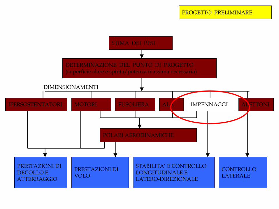
STIMA DEI PESI
DETERMINAZIONE DEL PUNTO DI PROGETTO (superficie alare e spinta/potenza massima necessaria)
IPERSOSTENTATORI FUSOLIERA ALA IMPENNAGGI ALETTONI
POLARI AERODINAMICHE
CONTROLLO LATERALE
STABILITA’ E CONTROLLO LONGITUDINALE E LATERO-DIREZIONALE
PRESTAZIONI DI VOLO
PRESTAZIONI DI DECOLLO E ATTERRAGGIO
DIMENSIONAMENTI
PROGETTO PRELIMINARE
MOTORI
The design of the vertical tail
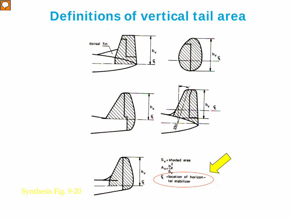
Definitions of vertical tail area
Synthesis Fig. 9-20
Relatore
Note di presentazione
When the tail is attached to the fuselage, it is mirrored into that, which increases the fin’s effective aspect ratio. This effect can also be explained as lift carry-over: the pressure differential does not stop abruptly at the junction of tail and fuselage. However, while for the horizontal tail the “fuselage-hidden” tail part is considered as effective horizontal tail surface, this does not happen concerning the vertical tail. As shown in the figure, the position of the horizontal stabilizer fixes the boundary for the fin effective area to be considered.
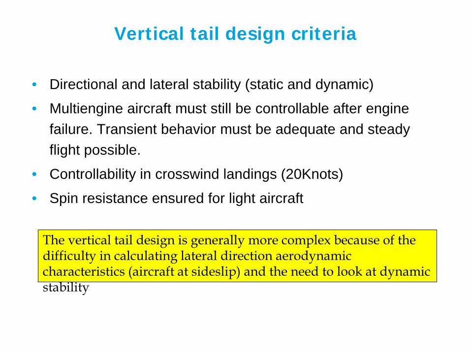
Vertical tail design criteria
• Directional and lateral stability (static and dynamic)
• Multiengine aircraft must still be controllable after engine failure. Transient behavior must be adequate and steady flight possible.
• Controllability in crosswind landings (20Knots)
• Spin resistance ensured for light aircraft
The vertical tail design is generally more complex because of the difficulty in calculating lateral direction aerodynamic characteristics (aircraft at sideslip) and the need to look at dynamic stability
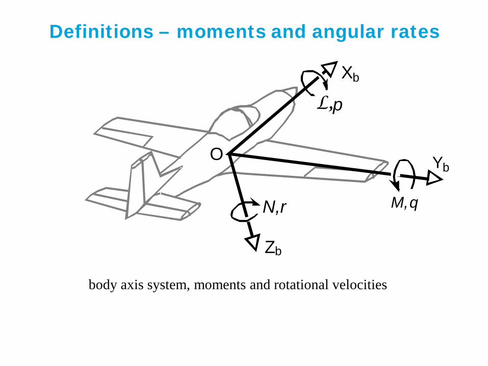
Definitions – moments and angular rates
Y b
L, p
M, q
body axis system, moments and rotational velocities
X b
Z b
N,r
O

Directional stability
β V
X b
l v
Y v (-)
Y b
fuselage yawing moment
vertical tail yawing moment
fuselage side force
vertical tail side force
Cnβ > 0 for directional stability
(this is the “Cmα counterpart” for directional stability)
Weathercock stability
Relatore
Note di presentazione
By definition, the sideslip angle is positive when the airspeed direction invests the right side of the aircraft. A directionally stable aircraft must react with a positive momentum around the vertical axis. Regulations imposes a positive directional static stability (note a statically directionally stable aircraft is not necessarily dynamically directionally stable) Typical Cnβ value ranges: 0.04 - 0.1 1/rad for subsonic single engine aircraft 0.10 - 0.25 1/rad for other transport aircraft Both fuselage, wing and vertical tail generate aerodynamic forces in correspondence of a sideslip angle. Unfortunately the (generally destabilizing) contribution of the fuselage to the system of aerodynamic forces is difficult to estimate. Also the way the wing-fuselage system affects the airflow on the vertical tail is difficult to estimate. However, accounting for these effects is required for a proper sizing of the vertical tail.
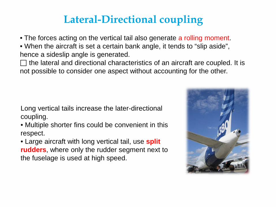
Lateral-Directional coupling • The forces acting on the vertical tail also generate a rolling moment. • When the aircraft is set a certain bank angle, it tends to “slip aside”, hence a sideslip angle is generated. the lateral and directional characteristics of an aircraft are coupled. It is not possible to consider one aspect without accounting for the other.
Long vertical tails increase the later-directional coupling. • Multiple shorter fins could be convenient in this respect. • Large aircraft with long vertical tail, use split rudders, where only the rudder segment next to the fuselage is used at high speed.

Directional stability
Gerlach
Directional (dynamic) stability is often the critical design case for aircraft with fuselage-mounted engine(s), rather than directional control. Two lateral/directional eigen-motions can be distinguished:
Spiral mode
Dutch roll
Relatore
Note di presentazione
Spiral mode must be stable or instability not too large. A small dihedral, or any configuration with associated dihedral effect, prevents spiral instability. A too laterally stable aircraft however is not ideal for lateral controllability (ability to roll). Besides, too large spiral stability can ease Dutch Roll instability. Proper yaw damping system can fix the problem.
Directional stability
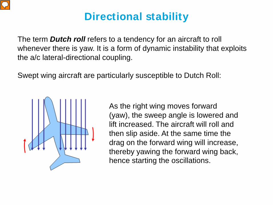
The term Dutch roll refers to a tendency for an aircraft to roll whenever there is yaw. It is a form of dynamic instability that exploits the a/c lateral-directional coupling. Swept wing aircraft are particularly susceptible to Dutch Roll:
As the right wing moves forward (yaw), the sweep angle is lowered and lift increased. The aircraft will roll and then slip aside. At the same time the drag on the forward wing will increase, thereby yawing the forward wing back, hence starting the oscillations.
Relatore
Note di presentazione
One wing yawing forward in this situation changes the effective span between left and right wings (the sweep angle of right and left wing change). The wing yawed forward momentarily creates more lift than the one of the other side. The result is that the forward wing rises and starts a rolling movement. The problem is aggravated by the fact that the forward wing, due to its increased lift, also has more drag, pulling that wing back once again and starting an oscillation in the other direction Swept wing aircraft are particularly susceptible, and many are equipped with yaw damper, which is an automatic device that senses yaw and counters it with corrective control inputs before the Dutch roll oscillations can develop.
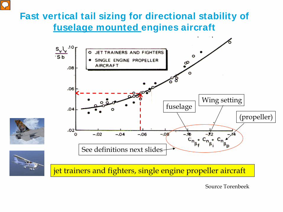
Fast vertical tail sizing for directional stability of fuselage mounted engines aircraft
jet trainers and fighters, single engine propeller aircraft
See definitions next slides
fuselage (propeller)
Wing setting
Source Torenbeek
Relatore
Note di presentazione
This graph can be used a fast sizing method for the vertical tail volume of single engine of jet trainers and fighters, and single engine propeller aircraft (fuselage mounted engines). In these type of aircraft, stability considerations are generally driving the vertical tail sizing. The term in the vertical axis is the vertical tail volume coefficient (see definition in previous lectures) The propeller term is of course null for jet trainers and fighters
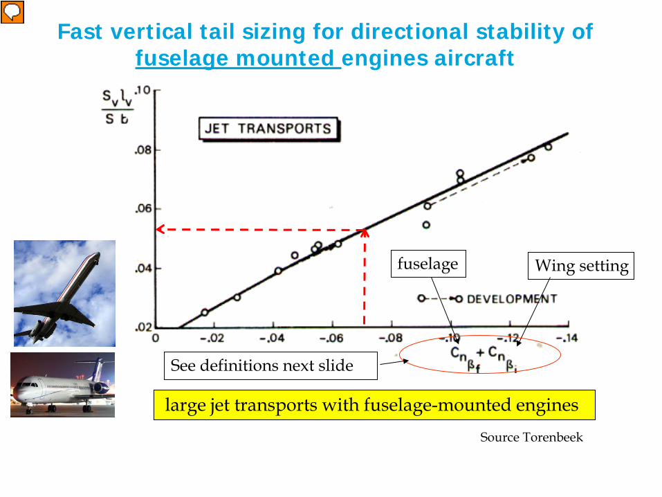
large jet transports with fuselage-mounted engines
See definitions next slide
fuselage Wing setting
Source Torenbeek
Fast vertical tail sizing for directional stability of fuselage mounted engines aircraft
Relatore
Note di presentazione
In these type of aircraft, stability considerations are generally driving the vertical tail sizing.

Directional stability - definitions
where, for lf/hfmax >3.5,
-0.017, high wing +0.012, mid wing +0.024, low wing
Source Torenbeek
=inC
β
1 2
2 1
max
1/ 2 1/ 3
0.3 0.75 0.105
f
f ffs fn
f f
fcg
f f
h bS lC kSb h b
hlk
l l
β β
β
= −
= + −
2
0.0503p
p pn p
l DC B
Sbβ= − ∑0.053
fuselage
propeller Wing setting
Relatore
Note di presentazione
Dp is the propeller disk diameter; Bp is the number of blades per propeller; lp is the distance from the (tractor) propeller plane to the aircraft c.g. ATT: the propeller contribution is the summation of the term above for all operating propellers (not very common to have more than one)

Directional control after engine failure The critical design case for wing-mounted engines is control after engine failure at VMCA.
Source Torenbeek
Relatore
Note di presentazione
In case of aircraft with wing mounted engines, the critical design case for the vertical tail is generally dictated by the one engine out situation (N-1) at minimum control speed in the air (VMCA), rather than by stability considerations. Hence the fast sizing method presented before cannot be used here. Of course the fin and rudder must allow controlling the aircraft also in case of one engine out during ground acceleration. However the stabilizing effect of the landing gears makes this design case less critical than in the air. If one engine stops, a yaw moment turns the aircraft toward the stopped engine (this yaw moment can be aggravated by the extra drag generated by windmilling propeller or fan blades). This yawing moment must be counteracted by the fin and rudder which must generate and opposite yaw moment. The aircraft will find an equilibrium for a small sideslip angle. However the load on the tail will also cause a rolling moment down the stopped engine. The pilot uses the ailerons to bank in the opposite direction, hence putting down the working engine in order to balance the tail rolling moment with the a weight component. This will require some extra lift to be generated, hence the elevator must be used to trim the aircraft at a higher angle of attack.
Synthesis
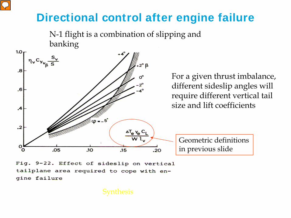
N-1 flight is a combination of slipping and banking
For a given thrust imbalance, different sideslip angles will require different vertical tail size and lift coefficients
Geometric definitions in previous slide
Directional control after engine failure
Relatore
Note di presentazione
Accepting to fly at a negative sideslip angle (when right engine inoperative) makes it possible to use a smaller vertical tailplane, as compared with β = 0 (see plot above). However, the condition imposed by the angle of bank of 5 degrees limits the usable sideslip angle. For values of the figure of merit plotted in the abscises (see plot above) larger than 0.15 (about), this limit will increase the requied control capacity considerably. Cyvβ is the fin lift coefficient (the side force coefficient), which is the fin counterpart of the wing and horizontal tail CL. The larger the accepted sideslip angle the smaller the required tail size. The maximum lift coefficient and the minimum weight are actually sizing the vertical tail. Although illustrative, the graph above is difficult to be used in practice, mainly because of the difficult estimation of the ratio of the freestream speed and the speed at the tail (ηv).
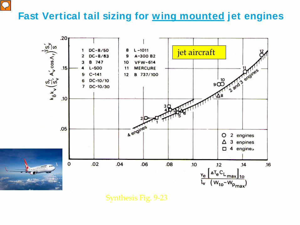
Fast Vertical tail sizing for wing mounted jet engines
Synthesis Fig. 9-23
jet aircraft
Relatore
Note di presentazione
This graph can be used as fast vertical tail estimation method for jet aircraft with wing mounted engines. Different curves are provided for aircraft with different amount of engines. The entry value in the horizontal axis can be computed using the definitions given in the figure of slide 29 (delta Te= thrust asymmetry), plus other known (operational) parameters (Wpmax = maximum payload weight). Once found the value in the vertical axis, a ratio of the vertical tail wing surface and the rudder area can be estimated using preselected values of aspect ratio and sweep (see next slides and recommendation about rudder deflection angle not be larger than 25 degrees). You will need also some reference value concerning the ratio of vertical tail area taken by the rudder. You can find these data on the Roskam book (find a copy of the relevant part on BB, in the taildata folder)

Synthesis Fig. 9-23
propeller aircraft
Fast Vertical tail sizing for wing mounted prop engines
Relatore
Note di presentazione
This curve applies to propeller aircraft. See note previous slide
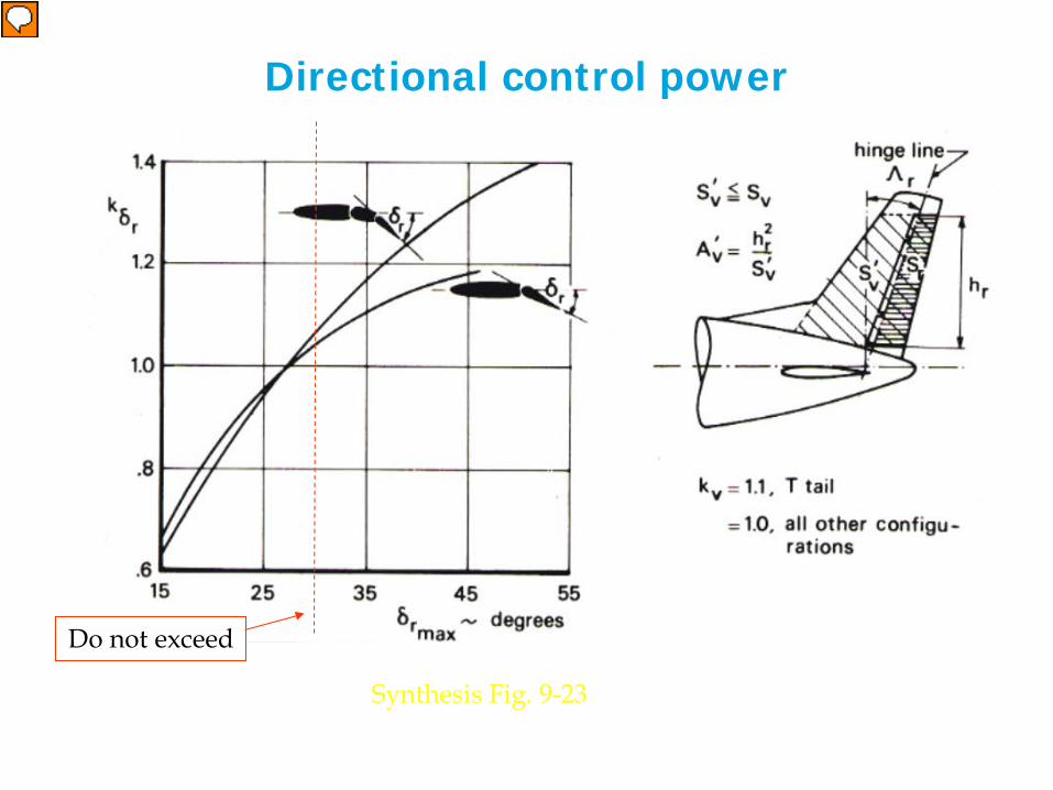
Directional control power
Synthesis Fig. 9-23
Do not exceed
Relatore
Note di presentazione
Approximate limit is: rudder chord of 30-35% tailplane chord with maximum rudder deflection not higher than 25-30 deg.
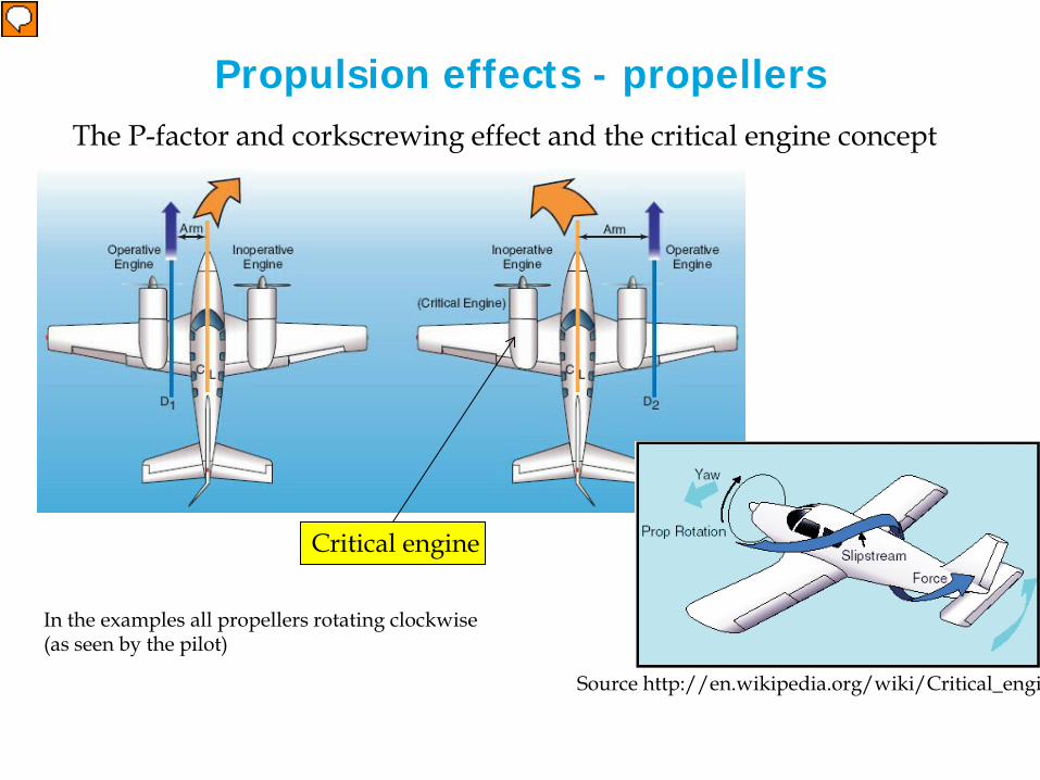
Propulsion effects - propellers The P-factor and corkscrewing effect and the critical engine concept
Source http://en.wikipedia.org/wiki/Critical_engi
In the examples all propellers rotating clockwise (as seen by the pilot)
Critical engine
Relatore
Note di presentazione
Source http://www.qmfc.org/school/asym.htm P-factor: asymmetric disk loading . For the effect to occur at all, you need to have an angle between the propeller axis and the relative wind. To be specific, imagine that the aircraft is in a nose-high attitude, but its direction of motion is horizontal (i.e. the relative wind is horizontal). Then the downgoing blade will be going down and a little bit forward, while the upgoing blade will be going up and a little bit backward. The downgoing blade will effectively have a slightly higher airspeed, hence will generate some more thrust. Corkscrewing slipstream the propeller slipstream follows a corkscrew-like trajectory, rotating as it flows back over the craft. That means the corkscrewing slipstream will strike the left side of the rudder, knocking the tail to the right, which makes the nose go to the left, which means you need right rudder to compensate. You don't notice the effect of the corkscrewing slipstream in cruise, because the aircraft designers have anticipated the situation. The vertical fin and rudder have been installed at a slight angle, so they are aligned with the actual airflow, not with the axis of the aircraft. Source http://en.wikipedia.org/wiki/Critical_engine Asymmetrical yaw When one engine becomes inoperative, a torque will be developed which depends on the lateral distance from the center of gravity (C.G.) to the thrust vector of the operating engine, multiplied by the thrust of the operating engine. The torque effect attempts to yaw the aircraft's nose towards the inoperative engine, a yaw tendency which must be counteracted by the pilot's use of the flight controls. Due to P-factor (assuming that both engines rotate clockwise when seen by the pilot), the right-hand engine typically develops its resultant thrust vector at a greater lateral distance from the aircraft's C.G. than the left-hand engine. The failure of the left-hand engine will result in a larger yaw effect via the operating right-hand engine, rather than vice-versa. Since the operating right-hand engine produces a stronger yaw moment, the pilot will need to use larger control deflections in order to maintain aircraft control. Thus, the failure of the left-hand engine is less desirable than failure of the right-hand engine, and the left-hand engine is critical. On aircraft with counterclockwise-turning engines, the right engine would be critical. Aircraft which have counter-rotating propellers rotating toward the cockpit on the top side do not have a critical engine, while both engines are critical on aircraft with counter-rotating propellers turning away from the cockpit. Accelerated Slipstream On aircraft with propellers mounted on the wing, the propwash from the engine will accelerate the airstream over the portion of the wing directly behind the propeller. This results in greater lift behind the propeller than at other spots on the wing. From the P-factor effect, the right wing's center of lift will be further from the C.G. than the left-hand wing. While failure of either engine will cause a rolling motion towards the inoperative side, the rolling motion will be more severe with the right engine operating. Thus, the failure of the left-hand engine is critical. Again, this example depends on both engines turning clockwise when viewed from the pilot.
Other requirements on directional control
• N-1 take-off (VMCG) or crosswind landing is highly dynamic and in ground effect and cannot be dealt with analytically. • The requirement for take-off is that the aircraft may not veer-off the centerline by more than 30 ft. • For landing a demonstrated maximum crosswind capability is part of the certification and noted in the Airplane Flight Manual.
Synthesis Eq. 9-68
Relatore
Note di presentazione
Vmcg = minimum control speed on the ground
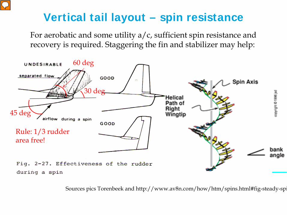
Vertical tail layout – spin resistance For aerobatic and some utility a/c, sufficient spin resistance and recovery is required. Staggering the fin and stabilizer may help:
Sources pics Torenbeek and http://www.av8n.com/how/htm/spins.html#fig-steady-spi
45 deg
30 deg
60 deg
Rule: 1/3 rudder area free!
Relatore
Note di presentazione
Source http://en.wikipedia.org/wiki/Spin_(flight) A spin is an aggravated stall resulting in rotation about the center of gravity wherein the aircraft follows a downward corkscrew path. Spins can be entered unintentionally or intentionally, from any flight attitude and from practically any airspeed—all that is required is sufficient yaw at the moment an aircraft stalls. A specific and often counterintuitive set of actions may be needed to effect recovery from spin. If the aircraft exceeds published limitations regarding spins, or is loaded improperly, or if the pilot uses incorrect technique to recover, the spin can lead to a fatal crash. In a spin, one wing is sufficiently stalled and generates significant drag but little or no lift, and the other is either not stalled or not stalled as fully as the other, and generates significant lift. This causes the aircraft to autorotate due to the non-symmetric lift and drag. Spins are characterized by high angle of attack, low airspeed, and high rate of descent. In order to exit from spin the use of rudder is essential, hence a proper tail configuration is required in order to have sufficient rudder surface available (not blanketed by the horizontal tail) to operate at high angle of attack and low speed Spins differ from spiral dives which are characterized by low angle of attack and high airspeed. A spiral dive is not a type of stall because the wing is not stalled and the airplane will respond to the pilot's inputs to the flight controls.

Vertical tail design
• in order to cope with large slip angles (up to 25°) fins have
low aspect ratio’s, large leading edge sweep, dorsal fins.
• For low aspect ratios sweep does not reduce the lift gradient • For low aspect ratios lift depends not on area, but on (height)2 only
2 21 12 2 2L
AL C V S V Sα
πα ρ α ρ= = =
22 2 21 1
2 2 2 2b V S b VS
π πα ρ α ρ= =
Relatore
Note di presentazione
Clalfa = A/2 is valid only for extremely low aspect ratio’s (ref. Obert AE4-211 )
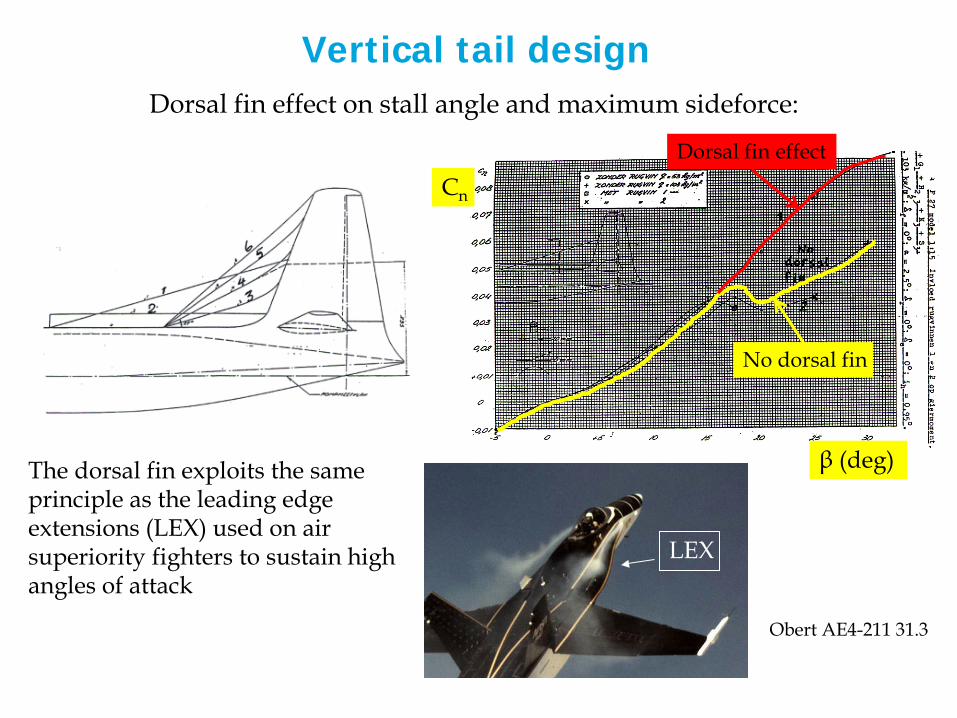
Vertical tail design Dorsal fin effect on stall angle and maximum sideforce:
Obert AE4-211 31.3
Cn
β (deg) The dorsal fin exploits the same principle as the leading edge extensions (LEX) used on air superiority fighters to sustain high angles of attack
LEX
No dorsal fin
Dorsal fin effect
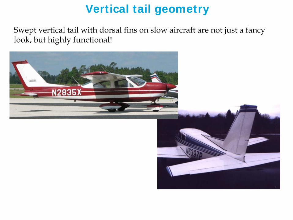
Vertical tail geometry
Swept vertical tail with dorsal fins on slow aircraft are not just a fancy look, but highly functional!

Vertical tail design parameters
Obert AE4-211 32.8
Jet aircraft • aspect ratio: 1.9 for low-set horizontal tails
1.2 – 1.5 for T-tails • taper ratio: 0.3 for low-set tailplanes 0.6 – 0.8 for T-tails • sweep: 35-45 degrees
Propeller aircraft • aspect ratio: 1.6 – 1.8 • taper ratio: 0.3 for low-set horizontal tails 0.5 – 0.7 for T-tails • sweep: 25-45 degrees
Find plenty of vertical tailplane data (volume coefficient and other geometry parameters) in the document ONLINE
horizontal and vertical tail combined
The design of the V tail
(butterfly tail)

V-tail configuration aircraft
Cirrus jet
Predator
Beech Bonanza Fouga magister
Eclipse 400
Relatore
Note di presentazione
The eclipse and the cirrus concept jets exploit the V tail configuration with the centreline installation of the jet engine. Possibly some noise shielding can be obtained to facilitate certification.
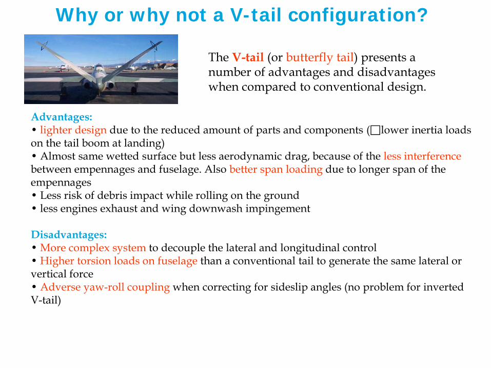
Why or why not a V-tail configuration?
Advantages: • lighter design due to the reduced amount of parts and components ( lower inertia loads on the tail boom at landing) • Almost same wetted surface but less aerodynamic drag, because of the less interference between empennages and fuselage. Also better span loading due to longer span of the empennages • Less risk of debris impact while rolling on the ground • less engines exhaust and wing downwash impingement Disadvantages: • More complex system to decouple the lateral and longitudinal control • Higher torsion loads on fuselage than a conventional tail to generate the same lateral or vertical force • Adverse yaw-roll coupling when correcting for sideslip angles (no problem for inverted V-tail)
The V-tail (or butterfly tail) presents a number of advantages and disadvantages when compared to conventional design.
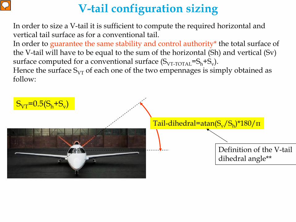
Tail-dihedral=atan(Sv/Sh)*180/π
V-tail configuration sizing In order to size a V-tail it is sufficient to compute the required horizontal and vertical tail surface as for a conventional tail. In order to guarantee the same stability and control authority* the total surface of the V-tail will have to be equal to the sum of the horizontal (Sh) and vertical (Sv) surface computed for a conventional surface (SVT-TOTAL=Sh+Sv). Hence the surface SVT of each one of the two empennages is simply obtained as follow:
SVT=0.5(Sh+Sv)
Definition of the V-tail dihedral angle**
Relatore
Note di presentazione
*ATT!: Sizing a Vtail by simply imposing the equality of the V-tail empennage projections on the horizontal and vertical plane respectively with the horizontal and vertical surface as computed for the conventional tail would yield an undersized Vtail! Using this approach indeed would guarantee the same longitudinal and lateral stability and controllability BUT ONLY ONE AT THE TIME! Actually the Vtail empennages should be able to deliver the same stability and controllability (of a conventional tail) on the lateral and longitudinal plane AT THE SAME TIME! “This is because of the need to be able to use full rudder and full elevator at the same time. If you make a V tail with the same PROJECTED area as your supposedly equivalent conventional tail, you will be able to make the same elevator force, or the same rudder force, but not both at the same time. For certain maneuvers (such as recovery from a spin), this difference can be very significant” ref. http://www.djaerotech.com/dj_askjd/askdesign.html The famous V-tail debate **Concerning the dihedral angle, experts have different opinions. Some suggest to consider the square of the ratio of vertical and horizontal tail, i.e.,Tail-dihedral=atan(Sv/Sh)2*180/π This would yield a more flat tail (smaller dihedral)

IL Progetto del Piano Verticale
1) INDIVIDUARE LE INCOGNITE
2) VALUTARE LE CONDIZIONI di Progetto
Corso Progetto Generale Velivoli 32
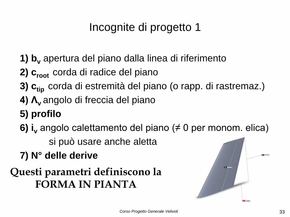
Incognite di progetto 1
1) bv apertura del piano dalla linea di riferimento 2) croot corda di radice del piano 3) ctip corda di estremità del piano (o rapp. di rastremaz.) 4) Λv angolo di freccia del piano 5) profilo 6) iv angolo calettamento del piano (≠ 0 per monom. elica) si può usare anche aletta 7) N° delle derive
Corso Progetto Generale Velivoli 33
Questi parametri definiscono la FORMA IN PIANTA

Incognite di progetto 2 8) cr/c (oppure cf/c) 9) cb/c bilanciamento 10) δr deflessioni p. mobile(+-25° o 30°) 11) Gtrasm = Δδ_trasm / Δdef_piano 12) Posizione (Xacv, Zacv) 13) TAB 14) Estensione TAB 15) Deflessione TAB 16) Dorsal fin (presente o meno)
Corso Progetto Generale Velivoli 34
Definita GEOMETRIA - CONTROLLO
- Trim(solitamente) - Anti-tab

Incognite di progetto 3 17) Materiale costruzione 18) Posizione longheroni(struttura) 19) Costi 20) DOC incidenza
Corso Progetto Generale Velivoli 35
Progetto completo
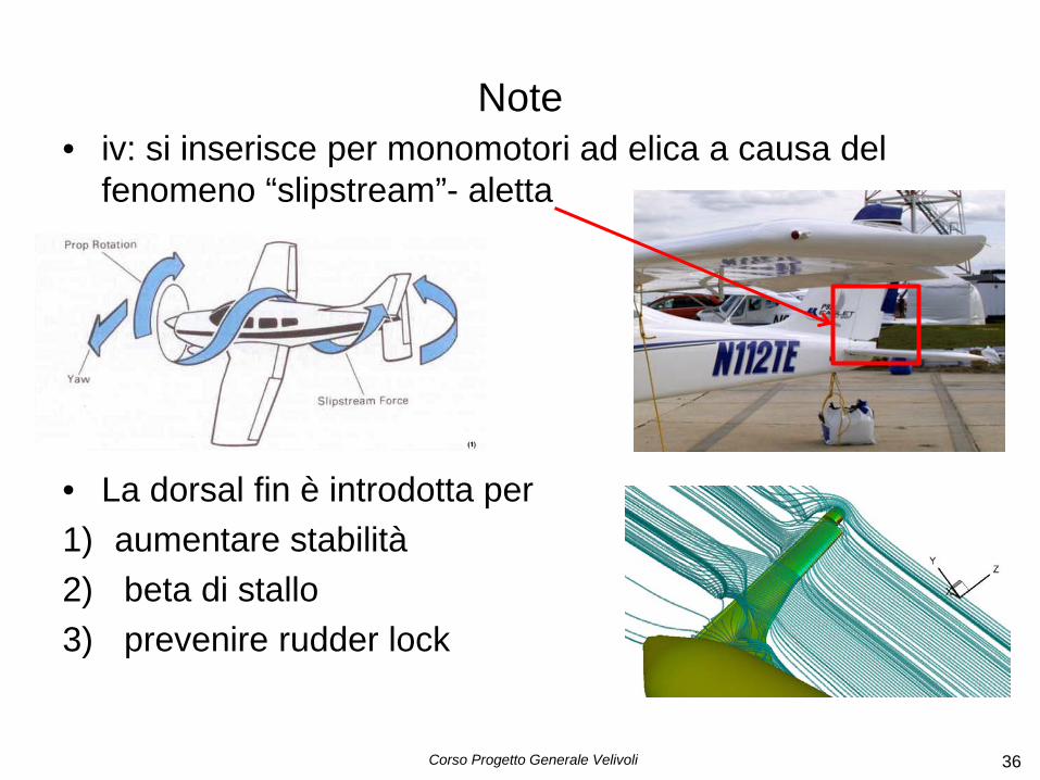
Note • iv: si inserisce per monomotori ad elica a causa del
fenomeno “slipstream”- aletta
• La dorsal fin è introdotta per 1) aumentare stabilità 2) beta di stallo 3) prevenire rudder lock
Corso Progetto Generale Velivoli 36

Incognite principali
• Sv • bv • cr/c Sr/Sv • δr
Corso Progetto Generale Velivoli 37
ARtail
Condizioni di progetto
Condizioni di VOLO critiche in cui i valori di una o più incognite sono massime(critiche per il progetto)
CONDIZIONI DI EQUILIBRIO
CONDIZIONI DI NON EQUILIBRIO(Manovra) SFORZI
Corso Progetto Generale Velivoli 38
Condizioni di progetto
• Condizioni di equilibrio – Decollo(VMC) E PIANTATA MOTORE – Atterraggio – Crociera – Stallo (raggiungimento dello stallo) – Rollio (prestazione di rollio) – Sforzi pedaliera
Corso Progetto Generale Velivoli 39
• Vite (monomotori)
Per tutte le fasi bisognerebbe valutare se con delta rudder max si riescano ad equilibrare 20° di derapata
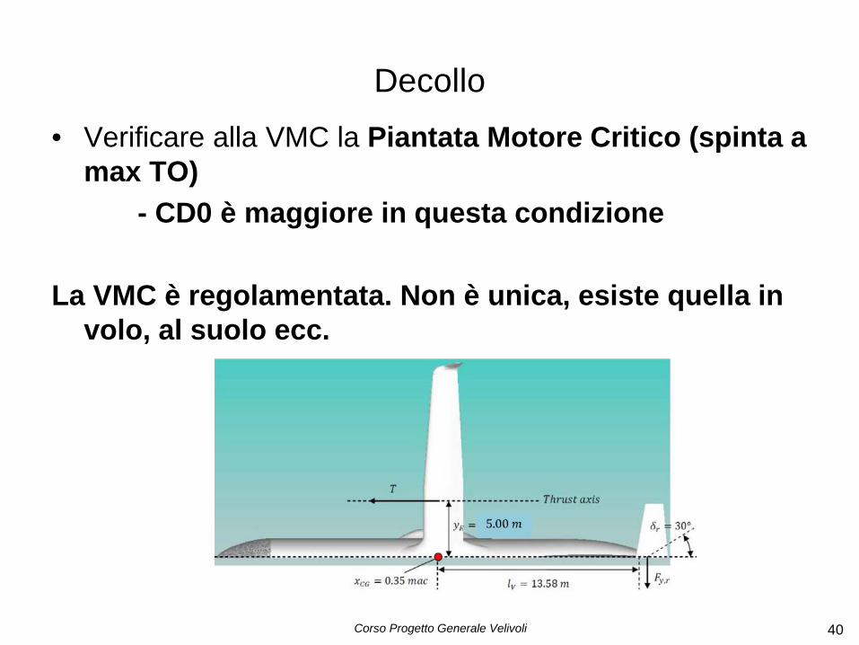
Decollo • Verificare alla VMC la Piantata Motore Critico (spinta a
max TO) - CD0 è maggiore in questa condizione La VMC è regolamentata. Non è unica, esiste quella in
volo, al suolo ecc.
Corso Progetto Generale Velivoli 40
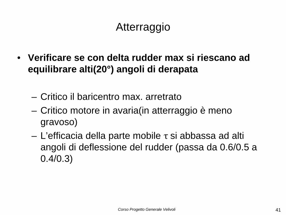
Atterraggio
• Verificare se con delta rudder max si riescano ad equilibrare alti(20°) angoli di derapata
– Critico il baricentro max. arretrato – Critico motore in avaria(in atterraggio è meno
gravoso) – L’efficacia della parte mobile τ si abbassa ad alti
angoli di deflessione del rudder (passa da 0.6/0.5 a 0.4/0.3)
Corso Progetto Generale Velivoli 41

Corso Progetto Generale Velivoli 42
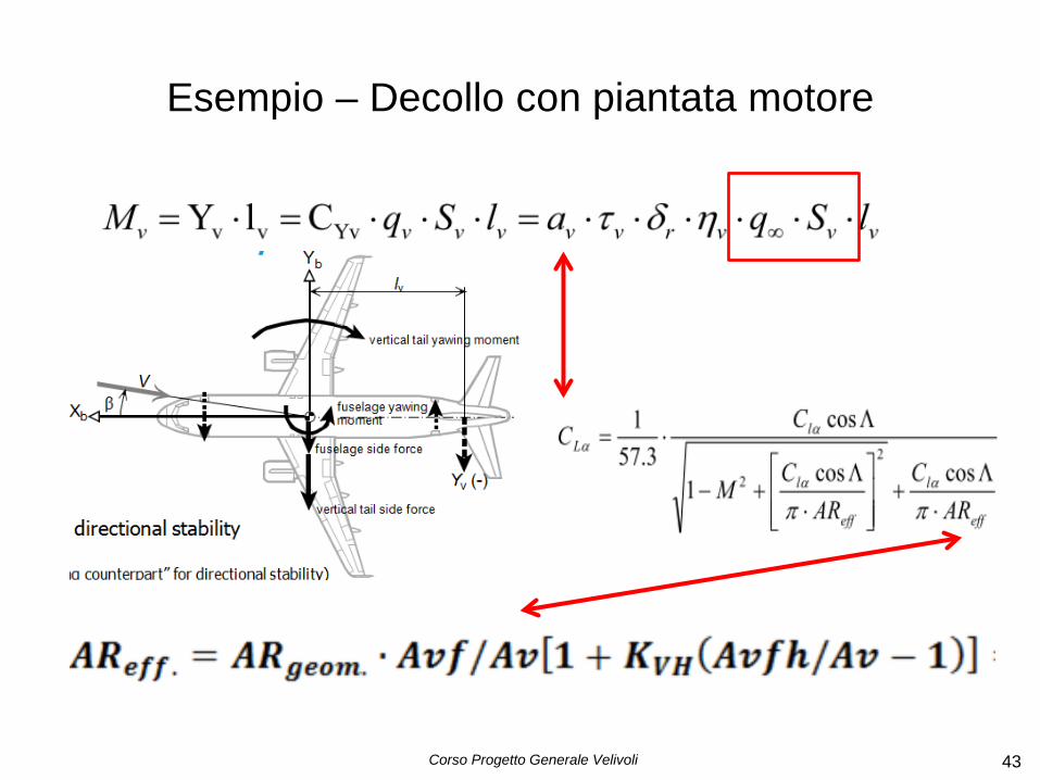
Esempio – Decollo con piantata motore
Esempio – Decollo con piantata motore
Corso Progetto Generale Velivoli 43
Corso Progetto Generale Velivoli 44
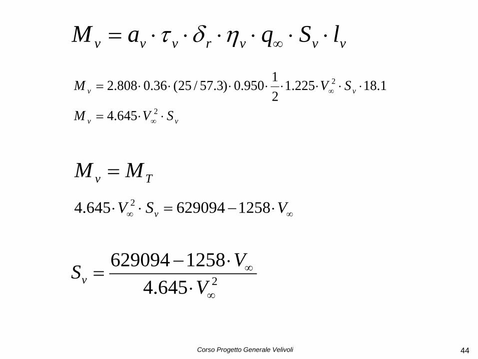
vvvrvvv lSqaM ⋅⋅⋅⋅⋅⋅= ∞ηδτ
vv
vv
SVM
SVM
⋅⋅=
⋅⋅⋅⋅⋅⋅⋅⋅=
∞
∞
2
2
645.4
1.18225.121950.0)3.57/25(36.0808.2
Tv MM =
∞∞ ⋅−=⋅⋅ VSV v 1258629094645.4 2
2645.41258629094
∞
∞
⋅⋅−
=V
VSv
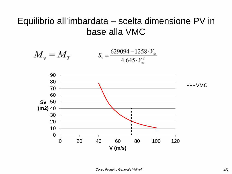
Equilibrio all’imbardata – scelta dimensione PV in base alla VMC
Corso Progetto Generale Velivoli 45
0102030405060708090
0 20 40 60 80 100 120
Sv (m2)
V (m/s)
VMC

Corso Progetto Generale Velivoli 46
Esempio – Decollo con piantata motore
0100000200000300000400000500000600000700000800000900000
1000000
0 20 40 60 80 100 120 140
M (Nm)
V (m/s)
M_VMt
Per una data Sv si ha equilibrio ad una V
∞∞ ⋅−=⋅⋅ VSV v 1258629094645.4 2
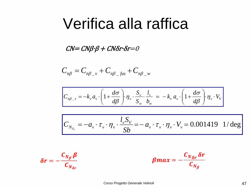
Verifica alla raffica
Corso Progetto Generale Velivoli 47
wnfusnvnn CCCC ___ ββββ ++=
Vvvvw
v
w
vvvvvn V
ddak
bl
SS
ddakC ⋅⋅
+⋅−=⋅⋅⋅
+⋅−= η
βση
βσ
β 11_
CN= CNβ∙β + CNδr∙δr=0
deg/1001419.0r
=⋅⋅⋅−=⋅⋅⋅−= vvvvVv
vvvN VaSbSlaC ητητ
δ