
OMATP32E - bricensw.com.aubricensw.com.au/wp-content/uploads/2014/05/OMATP32E.Mincer_Man.pdf · In...
16
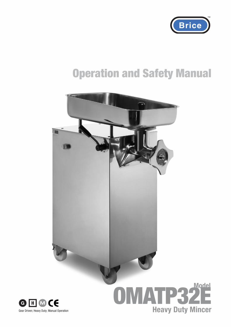
Heavy Duty Mincer OMATP32E Model Gear Driven; Heavy Duty; Manual Operation Operation and Safety Manual
Transcript of OMATP32E - bricensw.com.aubricensw.com.au/wp-content/uploads/2014/05/OMATP32E.Mincer_Man.pdf · In...
Heavy Duty MincerOMATP32E
Model
Gear Driven; Heavy Duty; Manual Operation
Operation and Safety Manual
Operation and Safety Manual™
OMATP32E Mincer2
I Parte 1
1
Gentile Cliente
I tritacarne e i loro accessori sono stati costruiti secondo la Direttiva macchine 2006/42 CEE e successive modifi cazioni, per rispondere ai requisiti richiesti dalla legislazione alla data di costruzione.Caratteristiche fondamentali sono la facilita’ di pulizia, la robustezza della costruzione, la sicurezza e l’affi dabilita’ di funzionamento.I materiali utilizzati, alluminio anodizzato e acciaio inox, sono stati scelti nel rispetto delle normative igienico sanitarie, per rendere la macchina inalterabile nel tempo.
Le normative che regolamentano la costruzione sono:
EN 12331 Macchine per la lavorazione della carne - Tritacarne - Norme per la sicurezza e l’igiene
EN 60204 Equipaggiamento elettrico delle macchine: Parte 1 - Regole generali
89/109CEE Direttiva per i materiali e gli oggetti destinati a venire a contatto con i prodotti alimentari.
Regolamento CE n. 1935/2004 Riguardantei materiali e gli oggetti destinati a venire a contatto con i prodotti alimentari
2004/108/CEE Direttiva sulla Compatibilità Elettromagnetica (EMC)
2006/95/CEE Direttiva bassa tensione
2002/95/CE RoHS- Sulla restrizione dell’uso di determinate sostanze pericolose nelle apparecchiature elettriche ed elettroniche.
La Dichiarazione CE di Conformità, lo schema elettrico sono allegati al presente Manuale che, per una corretta installazione e utilizzo della macchina, consigliamo di leggere attentamente.
Ci auguriamo che possiate apprezzare le prestazioni dei nostri prodotti.
Cordialmente
Part 1GB
Dear Customer,
The meat mincer and their accessories are manufactured in accordance with the EEC2006/42 Machinery directive and further modifi cations. They meet all legislative requirements valid at the date of manufacture.Its principle characteristics are easy cleaning, robust manufacture, safe and reliable operation.The materials utilized, anodized aluminium and stainless steel, have been selected with due regard to hygiene regulations and ensure that the machine has a long life.
The regulations applicable to its manufacture are the following:
EN 12331 Meat processing machinery - mincing machines - safety and hygiene requirements
EN 60204 Electric equipment of machines: Part 1 General requirements
EEC 89/109 Directives for the materials and things destined to come into contact with food.
Rule CE n. 1935/2004 for the materials and things destined to come into contact with food.
2004/108/EEC Directive on Electromagnetic Compatibility (EMC).
2006/95/EEC Directive on low voltage.
2002/95/CE (RoHS - Restriction of Hazardous Substances).
The EEC Declaration of Conformity and the circuit diagram are delivered together with the instruction manual, that we recommend to read with great attention for a correct installation and use of the machine.
We hope that you can make the best use of the performance of our products.
Yours faithfully.
Parte 3
22 3
Note generali alla consegnaLa macchina viene sempre conse-gnata adeguatamente imballata. Alla consegna controllare che l’imballo sia integro e che la for-nitura corrisponda all’ordine o al documento di accompagnamento. In caso contrario informare imme-diatamente lo spedizioniere.
I componenti dell’imballo (cartone, sacchi di polietilene, poliuterano espanso), sono assimilabili ai rifi uti solidi urbani, lo smaltimento avviene senza diffi coltà. Non di-sperdere nell’ambiente.Direttiva 2002/96/CE RAEE: Conferire la macchina alla ditta costruttrice, per effettuare lo smaltimento a norma di legge.
Elenco componenti
1 Tritacarne
2 Tramoggia
3a Pestello polietilene
3b Pestello inox
4 Dichiarazione CE di Conformità
5 Manuale d’uso
6 Schema elettrico
Identifi cazione della macchinaPer qualsiasi informazione, rivolgersi al costruttore, citando sempre il numero di matricola r iportato sul la targhetta di identifi cazione.
6
3a
1
4
5
3b
2
Part 3
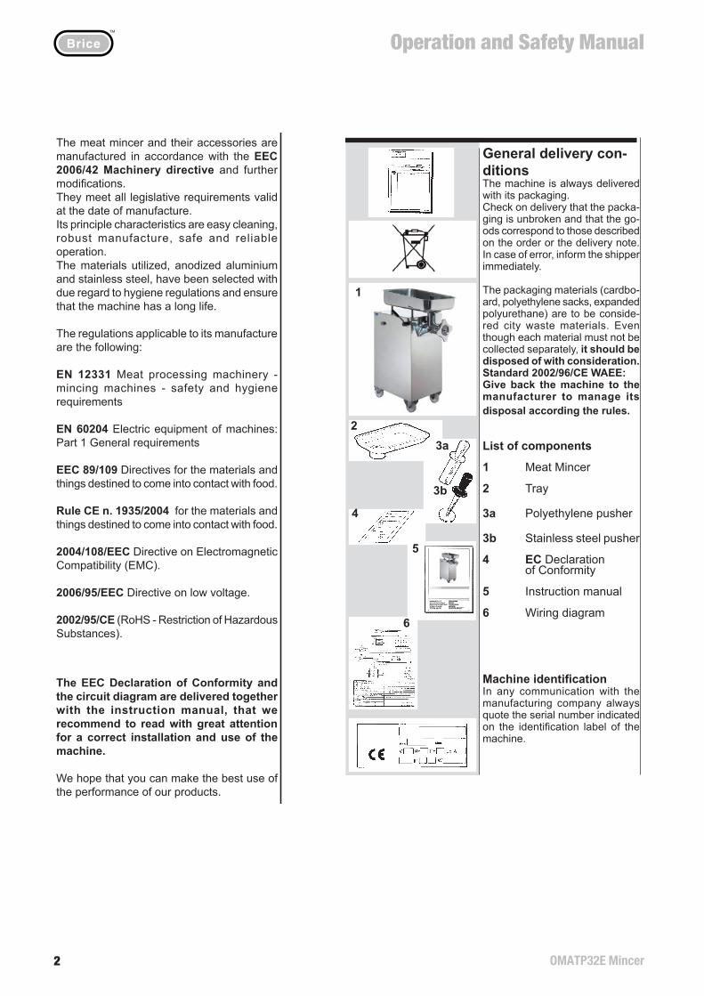
General delivery con-ditionsThe machine is always delivered with its packaging.Check on delivery that the packa-ging is unbroken and that the go-ods correspond to those described on the order or the delivery note. In case of error, inform the shipper immediately.
The packaging materials (cardbo-ard, polyethylene sacks, expanded polyurethane) are to be conside-red city waste materials. Even though each material must not be collected separately, it should be disposed of with consideration. Standard 2002/96/CE WAEE:Give back the machine to the manufacturer to manage its disposal according the rules.
List of components
1 Meat Mincer
2 Tray
3a Polyethylene pusher
3b Stainless steel pusher
4 EC Declaration of Conformity
5 Instruction manual
6 Wiring diagram
Machine identifi cationIn any communication with the manufacturing company always quote the serial number indicated on the identifi cation label of the machine.
Operation and Safety Manual™
OMATP32E Mincer 3
Parte 4
4 21
Piastra
Piastrasgrossatrice
Coltello doppio tagliente
Piastra
Distanziale
Ghiera
Gruppo taglio un passaggio
Gruppo taglio due passaggi
Gruppo taglio tre passaggi
Pulsantiera
Impugnatura di bloc-caggio gruppo taglio
Tramoggia
Canotto
Pestello
Pestello
Piastra di protezione
Apertura di alimentazione
Elica di lavoro
Coltello
10
11
12
13
14
15
A
B
C
1
2
3
4
5a
5b
6
7
8
9
B
8 9
10 15A5a
11
15
128
9 14
Defi nizione componenti
C 11 14
128
13 915
12
5b
10
11
12
13
14
15
A
B
C
1
2
3
4
5a
5b
6
7
8
9
4
2
3
1
67
1b 1c
1a Pulsante Reverse1b Pulsante Stop1c Pulsante Start
1a
Part 4
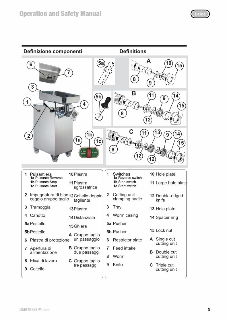
Hole plate
Large hole plate
Double-edgedknife
Hole plate
Spacer ring
Lock nut
Single cut cutting unit
Double cut cutting unit
Triple cut cutting unit
Switches
Cutting unitclamping hadle
Tray
Worm casing
Pusher
Pusher
Restrictor plate
Feed intake
Worm
Knife
Defi nitions
1a Reverse switch1b Stop switch1c Start switch
Operation and Safety Manual™
OMATP32E Mincer4
Parte 5
20
Caratteristiche tecniche
Caratteristichemotore
W HzV
1800 1~
3000 400 3~
N°.
Fasi
Phas
e N
°.
50
CL
Col
lega
men
ti
Serv
izio
Serv
ice
Con
nect
ion
nmin
1
2
3
4
5
6
7
Dimensioni (mm)
Peso Kg
Senza imballo
Con imballo
Temperatura di utilizzo
Rumorosita’ dB
Grado di protezione impianto elettrico e comandi
5
1
2
3
4
5
6
7
1450 B S1
1
TP 32E
A 800B 550C 430D 1100 E 460F 670 127 145
+5 °C ÷ +40 °C<70
IP 65
567
234
Parte 10
Nel caso le soluzioni proposte non risolvono l’anomalie indi-cate, interpellare l’assistenza.
ANOMALIALa macchina vibra, surriscalda, emana un cattivo odore
SoluzioneFermare la macchina e controllare che la tensione corrisponda ai dati di targa (pag. 5)
ANOMALIALa carne é lavorata in modo irregolare.
SoluzioneControllare che il gruppo taglio é montato correttamente (pag. 17).Controllare se le piastre e i coltelli sono usurate, in questo caso sostituire i componenti.
ANOMALIAIl perno dell’ elica é partico-larmente usurato.
SoluzioneChiamare l’Assistenza per la sostituzione.
230
Part 5
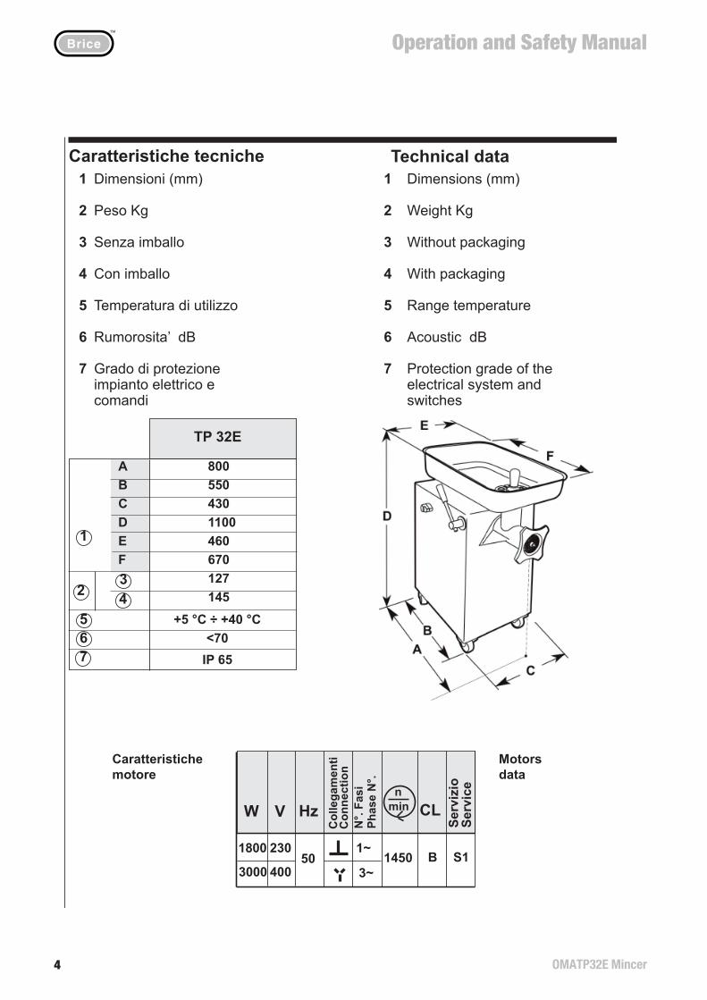
Technical dataDimensions (mm)
Weight Kg
Without packaging
With packaging
Range temperature
Acoustic dB
Protection grade of the electrical system and switches
Motorsdata
Part 10
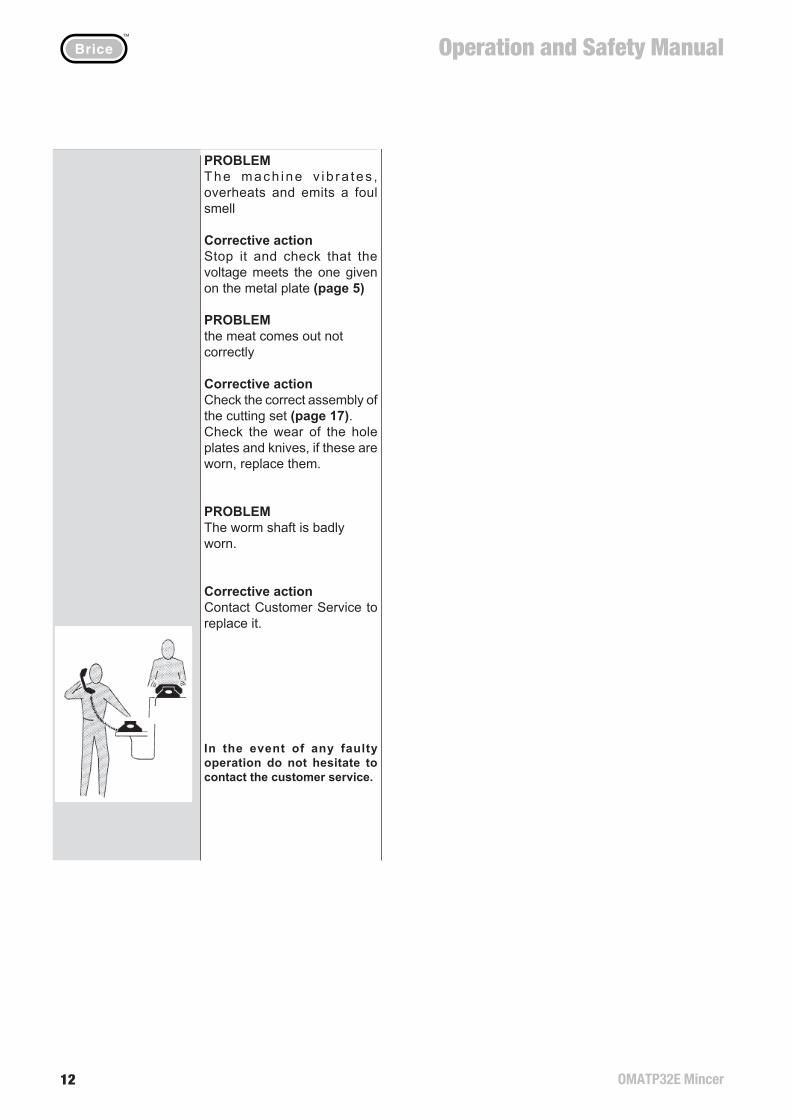
In the event of any faulty operation do not hesitate to contact the customer service.
PROBLEMThe mach ine v ib ra tes , overheats and emits a foul smell
Corrective actionStop it and check that the voltage meets the one given on the metal plate (page 5)
PROBLEMthe meat comes out not correctly
Corrective actionCheck the correct assembly of the cutting set (page 17).Check the wear of the hole plates and knives, if these are worn, replace them.
PROBLEMThe worm shaft is badly worn.
Corrective actionContact Customer Service to replace it.
Operation and Safety Manual™
OMATP32E Mincer 5
Parte 6
6 19
Installazione
La collocazione della macchi-na deve essere effettuato da due persone.
Il tritacarne deve essere collo-cato su una superfi cie piana orizzontale e antiscivolo.
Prima di utilizzare la macchina, bloccare le ruote posteriori.
Allacciamento elettricoLa macchina deve essere installata vicino ad una presa di corrente. Controllare che la tensione corrisponda ai dati di targa e che la presa sia corredata di messa a terra.
Controllo senso di rotazione
IMPORTANTEEseguire il controllo del senso di rotazione, solo per le macchine con motore trifase.
PERICOLO: I componenti del gruppo taglio si possono seriamente danneggiare se il senso di rotazione dell’elica di lavoro non é corretto.
1 Seguire le istruzioni descritte nella pag. 18 “Operazione di rimozione gruppo taglio completo”
Parte 9
Operazione di montag-gio gruppo taglio com-pleto
Ruotare, in senso orario sino a fi ne corsa, l’impu-gnatura di bloccaggio delgruppo taglio.
Tenendo il canotto con due mani, appoggiarlo alla macchina facendo coin-cidere i bordi sporgenti delcanotto con quelli della macchina, e infilarlo nel corpo macchina.Assicurandosi che la sede quadrata dell’elica di lavoro coincida con il perno qua-drato di trascinamento, accostare il gruppo taglio al corpo macchina.
Ruotare, in senso antiora-rio,l’impugnatura di bloc-caggio sino ad ottenere ilblocco del canotto.
Avvitare la ghiera in sensoorario.
Montaggio tramoggia
Collocare il piatto raccogli-tore sotto il gruppo taglio.
6
7
8
9
10
11
12
Part 6
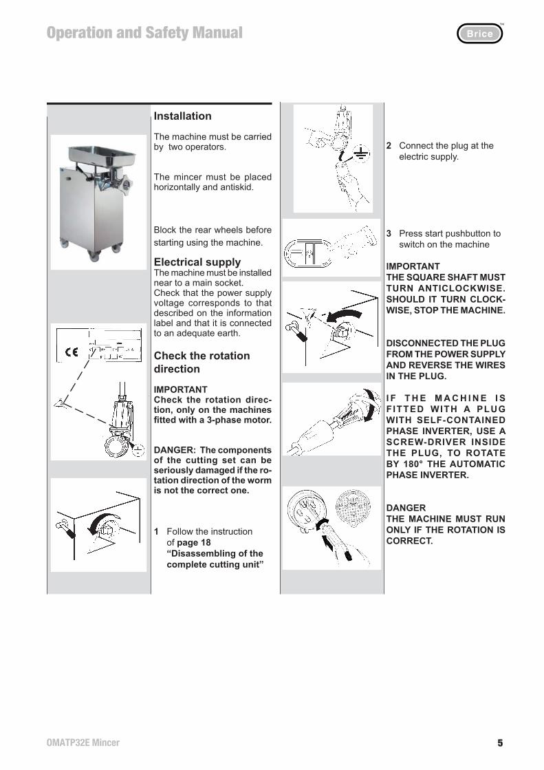
Installation
The machine must be carried by two operators.
The mincer must be placed horizontally and antiskid.
Block the rear wheels before starting using the machine.
Electrical supplyThe machine must be installed near to a main socket.Check that the power supply voltage corresponds to that described on the information label and that it is connected to an adequate earth.
Check the rotation direction
IMPORTANTCheck the rotation direc-tion, only on the machines fi tted with a 3-phase motor.
DANGER: The components of the cutting set can be seriously damaged if the ro-tation direction of the worm is not the correct one.
1 Follow the instruction of page 18 “Disassembling of the complete cutting unit”
Part 9
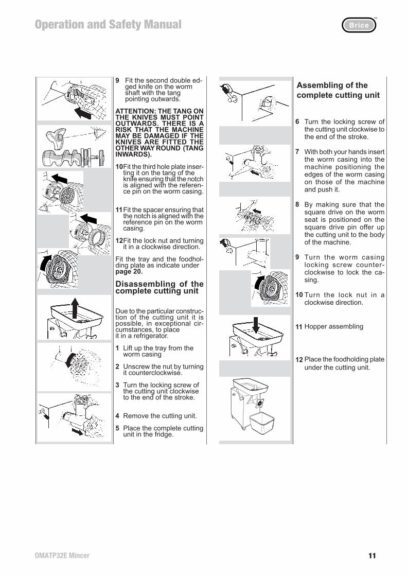
Assembling of the complete cutting unit
6
7
8
9
10
11
12
Turn the locking screw of the cutting unit clockwise to the end of the stroke.
With both your hands insert the worm casing into the machine positioning the edges of the worm casing on those of the machine and push it.
By making sure that the square drive on the worm seat is positioned on the square drive pin offer up the cutting unit to the body of the machine.
Turn the worm casing locking screw counter-clockwise to lock the ca-sing.
Turn the lock nut in a clockwise direction.
Hopper assembling
Place the foodholding plateunder the cutting unit.
Parte 6
18 7
2 Collegare la macchina alla presa di corrente
3 Premere il pulsante di start per avviare la macchina
IMPORTANTECONTROLLARE CHE IL PERNO QUADRATO RUOTI IN SENSO ANTIORARIO.IN CASO CONTRARIO FER-MARE LA MACCHINA.
TOGLIERE LA SPINA DAL-LA PRESA DI CORRENTE E INVERTIRE DUE FILI NELLA SPINA.
SE LA MACCHINA E’ DO-TATA DI UNA SPINA CON INVERTITORE DI FASE INCORPORATO, UTILIZ-ZANDO UN CACCIAVITE PREMERE E RUOTARE DI 180° PER OTTENERE L’IN-VERSIONE AUTOMATICA DELLE FASI.
PERICOLOLA MACCHINA DEVE FUN-ZIONARE SOLO SE IL SEN-SO DI ROTAZIONE E’ COR-RETTO.
Parte 99 Montare il secondo coltello a doppio tagliente sul per- no dell’elica con il codolo rivolto verso l’esterno.
ATTENZIONE: IL CODO-LO DEL COLTELLO DEVE ES-SERE RIVOLTO VERSO L’ESTERNO. PERICOLO DI GRAVE DANNEGGIAMENTO ALLA MACCHINA SE IL COL-TELLO VIENE MONTATO AL CONTRARIO (CODOLO VERSO L’INTERNO).
10 Montare la terza piastra, infi landola sul codolo del coltello e facendo coinci- dere la tacca con la spina di riferimento del canotto.
11 Montare il distanziale, fa- cendo coincidere la tacca con la spina di riferimento del canotto.
12 Montare la ghiera, avvitan- dola in senso orario.
Collocare la tramoggia e il piatto raccoglitore come indicato nella pag. 20.
Operazione di smon-taggio gruppo taglio completoData la particolare conforma-zione di costruzione, vi é la possibilità, in caso ecceziona-le, di riporre in frigo il gruppo taglio.
1 Sfi lare la tramoggia dal canotto
2 Allentare la ghiera, ruotan- dola in senso antiorario.
3 Ruotare, in senso orario sino a fi ne corsa, l’impugna- tura di bloccaggio del gruppo taglio.
4 Estrarre il gruppo taglio.
5 Riporre il gruppo taglio completo in frigorifero.
Part 6
2 Connect the plug at the electric supply.
3 Press start pushbutton to switch on the machine
IMPORTANTTHE SQUARE SHAFT MUST TURN ANTICLOCKWISE. SHOULD IT TURN CLOCK-WISE, STOP THE MACHINE.
DISCONNECTED THE PLUG FROM THE POWER SUPPLY AND REVERSE THE WIRES IN THE PLUG.
I F T H E M A C H I N E I S F ITTED WITH A PLUG WITH SELF-CONTAINED PHASE INVERTER, USE A SCREW-DRIVER INSIDE THE PLUG, TO ROTATE BY 180° THE AUTOMATIC PHASE INVERTER.
DANGERTHE MACHINE MUST RUN ONLY IF THE ROTATION IS CORRECT.
Part 99 Fit the second double ed- ged knife on the worm shaft with the tang pointing outwards.
ATTENTION: THE TANG ON THE KNIVES MUST POINT OUTWARDS. THERE IS A RISK THAT THE MACHINE MAY BE DAMAGED IF THE KNIVES ARE FITTED THE OTHER WAY ROUND (TANG INWARDS).
10Fit the third hole plate inser- ting it on the tang of the knife ensuring that the notch is aligned with the referen- ce pin on the worm casing.
11 Fit the spacer ensuring that the notch is aligned with the reference pin on the worm casing.
12Fit the lock nut and turning it in a clockwise direction.
Fit the tray and the foodhol-ding plate as indicate under page 20.
Disassembling of the complete cutting unit
Due to the particular construc-tion of the cutting unit it is possible, in exceptional cir-cumstances, to place it in a refrigerator.
1 Lift up the tray from the worm casing
2 Unscrew the nut by turning it counterclockwise.
3 Turn the locking screw of the cutting unit clockwise to the end of the stroke.
4 Remove the cutting unit.
5 Place the complete cutting unit in the fridge.
Operation and Safety Manual™
OMATP32E Mincer6
Parte 6
8 17
5 Premere il pulsante stop
6 Scollegare la macchina dalla presa di corrente
IMPORTANTEPulizia preliminare: termi-nato il controllo del senso di rotazione, pulire la macchina dall’olio di protezione.Riassemblare i componenti seguendo le istruzioni nella page 17.
Parte 9
Montaggio gruppo taglio a 2-3 passaggi1 Ruotare, in senso orario sino a fi ne corsa, l’impu- gnatura di bloccaggio del gruppo taglio.
2 Tenere il canotto con due mani, appoggiarlo al corpo macchina e spingerlo a fondo nella propria sede.
3 Ruotare in senso antiorario, l’impugnatura di bloccaggio sino ad ottenere il blocco del canotto.
4 Prendere con due mani l’elica di lavoro ed infi larla nel canotto
5 Assicurarsi che la sede quadrata dell’elica di lavoro coincida con il perno qua- drato di trascinamento, infi lare l’ elica di lavoro all’interno del canotto.
6 Montare la prima piastra (sgrossatrice) infi landola sul perno dell’elica, facen- do attenzione che la parte tagliente dei fori sia verso l’esterno.
7 Montare il coltello a doppio tagliente sul perno dell’elica con il codolo rivolto verso l’esterno.
ATTENZIONE: IL CODO-LO DEL COLTELLO DEVE ES-SERE RIVOLTO VERSO L’ESTERNO. PERICOLO DI GRAVE DANNEGGIAMEN-TO ALLA MACCHINA SE IL COLTELLO VIENE MONTA-TO AL CONTRARIO (CODO-LO VERSO L’INTERNO).
8 Montare la seconda piastra, infi landola sul codolo del coltello e facendo coincide- re la tacca con la spina di riferimento del canotto.
IMPORTANTE: Nel caso di gruppo taglio a 2 passaggi, proseguire dal punto 11
Part 6
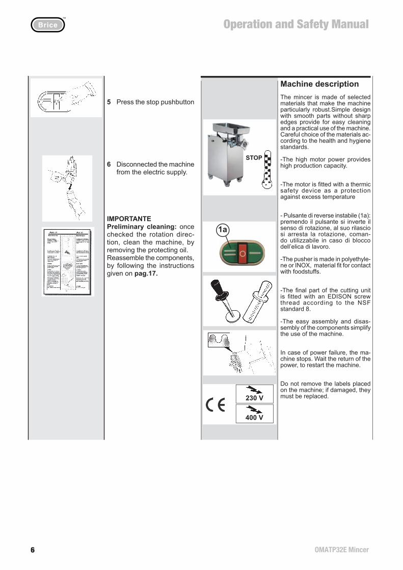
5 Press the stop pushbutton
6 Disconnected the machine from the electric supply.
IMPORTANTEPreliminary cleaning: oncechecked the rotation direc-tion, clean the machine, by removing the protecting oil.Reassemble the components, by following the instructions given on pag.17.
Part 9
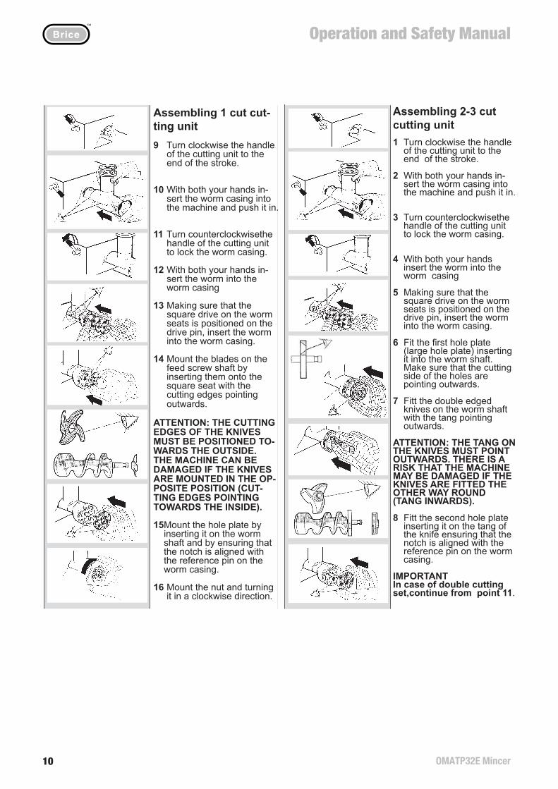
Assembling 2-3 cut cutting unit1 Turn clockwise the handle of the cutting unit to the end of the stroke.
2 With both your hands in- sert the worm casing into the machine and push it in.
3 Turn counterclockwisethe handle of the cutting unit to lock the worm casing.
4 With both your hands insert the worm into the worm casing
5 Making sure that the square drive on the worm seats is positioned on the drive pin, insert the worm into the worm casing.
6 Fit the fi rst hole plate (large hole plate) inserting it into the worm shaft. Make sure that the cutting side of the holes are pointing outwards.
7 Fitt the double edged knives on the worm shaft with the tang pointing outwards.
ATTENTION: THE TANG ON THE KNIVES MUST POINT OUTWARDS. THERE IS A RISK THAT THE MACHINE MAY BE DAMAGED IF THE KNIVES ARE FITTED THE OTHER WAY ROUND (TANG INWARDS).
8 Fitt the second hole plate inserting it on the tang of the knife ensuring that the notch is aligned with the reference pin on the worm casing.
IMPORTANTIn case of double cutting set,continue from point 11.
16 9
Parte 7
Descrizione macchinaIl tritacarne si distingue per l’ac-curata scelta dei materiali che lo rendono particolarmente robusto. Semplicità di linee e assenza di spigoli, conferiscono funzionalità e praticità nella pulizia e nell’uso del tritacarne. Scelta accurata dei materiali nel rispetto delle norma-tive igienico sanitarie.
-L’elevata potenza del motore, consente un’alta quantità di pro-duzione.
-Nel motore é inserito un disposi-tivo di sicurezza termico, di prote-zione contro le sovratemperature.
- Pulsante di reverse instabile(1a): premendo il pulsante si in-verte il senso di rotazione, al suo rilascio si arresta la rotazione, comando utilizzabile in caso di blocco dell’elica di lavoro.
-Il pestello é costruito in polietile-ne o acciaio INOX, amteriali adatti per il contatto con gli alimenti.
-La parte terminale del gruppotaglio é fornita di un fi letto ar-rotondato Edison, secondo la Normativa NSF standard 8.
-La semplicità delle operazionidi smontaggio e assemblaggio dei componenti consentono una estrema facilità d’ uso.
In mancanza della tensione di rete, la macchina si arresta. Attendere il ritorno della tensione di rete per riavviare la macchina.
Non manomettere le etichette collocate sulla macchina: in caso di danneggiamento sostituirle.
Montaggio gruppo taglio a 1 passaggio9 Ruotare, in senso orario sino a fi ne corsa, l’impu- gnatura di bloccaggio del gruppo taglio.
10 Tenere il canotto con due mani, appoggiarlo al corpo macchina e spingerlo a fondo nella propria sede.
11 Ruotare in senso antiora- rio, l’impugnatura di bloc- caggio sino ad ottenere il blocco del canotto.
12 Prendere con due mani l’elica di lavoro ed infi larla nel canotto.
13 Assicurandosi che la sede quadrata dell’elica di lavoro coincida con il perno qua- drato di trascinamento, infi lare l’ elica di lavoro all’interno del canotto.
14 Montare il coltello sul perno dell’elica di lavoro inserendolo nella sede quadrata, con i taglienti rivolti verso l’esterno.
ATTENZIONE: I TAGLIENTI DEL COLTELLO DEVONO ESSERE RIVOLTI VERSO L’ESTERNO. PERICOLO DI GRAVE DANNEGGIA-MENTO ALLA MACCHINA SE IL COLTELLO VIENE MONTATO AL CONTRARIO (TAGLIENTI VERSO L’IN-TERNO).
15 Montare la piastra, infi lan- dola sul perno dell’elica e facendo coincidere la tacca con la spina di riferi- mento del canotto.
16 Montare la ghiera, avvitan- dola in senso orario.
Parte 9
230 V
400 V
1a
STOP
Part 7
Machine descriptionThe mincer is made of selected materials that make the machine particularly robust.Simple design with smooth parts without sharp edges provide for easy cleaning and a practical use of the machine.Careful choice of the materials ac-cording to the health and hygiene standards.
-The high motor power provides high production capacity.
-The motor is fi tted with a thermic safety device as a protection against excess temperature
- Pulsante di reverse instabile (1a): premendo il pulsante si inverte il senso di rotazione, al suo rilascio si arresta la rotazione, coman-do utilizzabile in caso di blocco dell’elica di lavoro.
-The pusher is made in polyethyle-ne or INOX, material fi t for contact with foodstuffs.
-The fi nal part of the cutting unit is fi tted with an EDISON screw thread according to the NSF standard 8.
-The easy assembly and disas-sembly of the components simplify the use of the machine.
In case of power failure, the ma-chine stops. Wait the return of the power, to restart the machine.
Do not remove the labels placed on the machine; if damaged, they must be replaced.
Part 9
Assembling 1 cut cut-ting unit 9 Turn clockwise the handle of the cutting unit to the end of the stroke.
10 With both your hands in- sert the worm casing into the machine and push it in.
11 Turn counterclockwisethe handle of the cutting unit to lock the worm casing.
12 With both your hands in- sert the worm into the worm casing
13 Making sure that the square drive on the worm seats is positioned on the drive pin, insert the worm into the worm casing.
14 Mount the blades on the feed screw shaft by inserting them onto the square seat with the cutting edges pointing outwards.
ATTENTION: THE CUTTING EDGES OF THE KNIVES MUST BE POSITIONED TO-WARDS THE OUTSIDE.THE MACHINE CAN BE DAMAGED IF THE KNIVES ARE MOUNTED IN THE OP-POSITE POSITION (CUT-TING EDGES POINTING TOWARDS THE INSIDE).
15Mount the hole plate by inserting it on the worm shaft and by ensuring that the notch is aligned with the reference pin on the worm casing.
16 Mount the nut and turning it in a clockwise direction.
Operation and Safety Manual™
OMATP32E Mincer 7
Parte 7
10 15
Gli operatori non devono indos-sare indumenti svolazzanti o maniche aperte.
Durante il funzionamento non ci devono essere persone estranee nelle vicinanze del tritacarne.
L’uso della macchina é consentito solo agli operatori che seguono le istruzioni contenute in questo manuale.
Si possono utilizzare piastre con fori di diametro superiore a 8 mm, solo se la macchina é provvista di apposito dispositivo di sicurezza.
ATTENZIONE: LO SPESSORE DELLE PIASTRE, UTILIZZATE VERSO L’APERTURA DI SCA-RICO, NON DEVE ESSERE INFERIORE A 5mm.
ATTENZIONE: NON RIMUOVE-RE LA PIASTRA DI PROTEZIO-NE DELL’APERTURA DI ALI-MENTAZIONE DEL CANOTTO
ATTENZIONE: NON INTRODUR-RE CORPI ESTRANEI NELLA APERTURA DI ALIMENTAZIO-NE DEL CANOTTO.
Funzionamento e uso della macchinaI tritacarne macinano ogni tipo di carne, purché sia disossata e non congelata.Per ottenere una corretta maci-nazione , la carne deve avere una temperatura compresa trai 2 e 5 gradi Centigradi.
1 Assicurarsi che la macchina sia spenta
2 Collegare la macchina alla presa di corrente, controllare la di presa di terra.
3 Preparare la carne nelle di- mensioni adatte per l’inseri- mento nell’apertura di alimentazione del canotto.
4 Appoggiare la carne nella tra- moggia.
Parte 9
Rimozione componenti1 Svitare la ghiera, girandola in senso antiorario.
2a Togliere il distanziale (solo macchine a 2 o 3 passaggi)
2b Togliere piastre e coltelli.
3 Prendere con due mani l’elica di lavoro e sfi larla dal canotto
4 Ruotare, in senso orario sino a fi ne corsa, l’impu- gnatura di bloccaggio del gruppo taglio.
5 Estrarre il canotto
6 Immergere le singole parti in un contenitore di acqua calda con l’aggiunta di un comune detersivo per stovi- glie (evitare detergenti aggressivi che possono danneggiare le parti in alluminio del gruppo taglio).
7 Usare, se necessario uno scovolino a setole per ri- muovere i residui di sporco dalla elica di lavoro, dalla piastra, dal coltello e all’interno del canotto.
8 Sciacquare le parti in acqua corrente ed asciugarle.
ATTENZIONE: Occorre pre-stare particolare attenzione nel pulire l’interno dell’allog-giamento del canotto sul cor-po macchina. E’ possibile che, durante la lavorazione, si depositino dei residui di carne che devono essere rimossi, usare lo scovolino e un canovaccio.
Part 7
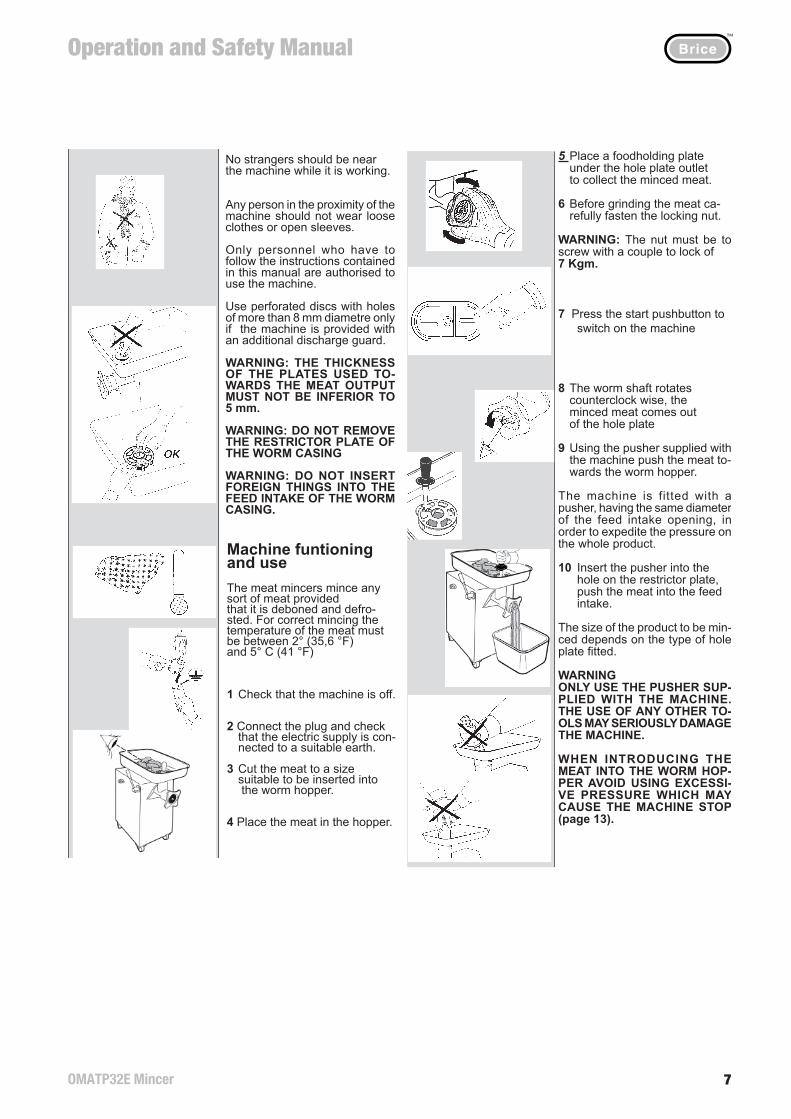
No strangers should be near the machine while it is working.
Any person in the proximity of the machine should not wear loose clothes or open sleeves.
Only personnel who have to follow the instructions contained in this manual are authorised to use the machine.
Use perforated discs with holes of more than 8 mm diametre only if the machine is provided with an additional discharge guard.
WARNING: THE THICKNESS OF THE PLATES USED TO-WARDS THE MEAT OUTPUT MUST NOT BE INFERIOR TO 5 mm.
WARNING: DO NOT REMOVE THE RESTRICTOR PLATE OF THE WORM CASING
WARNING: DO NOT INSERT FOREIGN THINGS INTO THE FEED INTAKE OF THE WORM CASING.
Machine funtioning and useThe meat mincers mince any sort of meat provided that it is deboned and defro-sted. For correct mincing the temperature of the meat must be between 2° (35,6 °F) and 5° C (41 °F)
1 Check that the machine is off.
2 Connect the plug and check that the electric supply is con- nected to a suitable earth.
3 Cut the meat to a size suitable to be inserted into the worm hopper.
4 Place the meat in the hopper.
Part 9
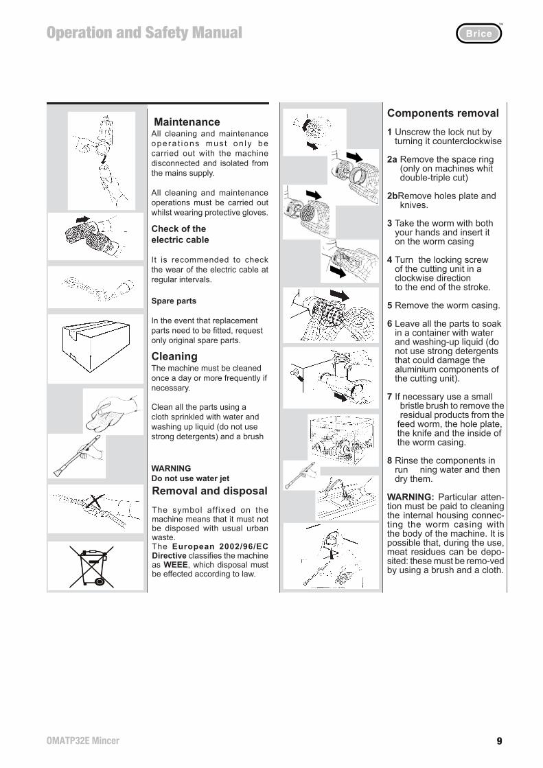
Components removal1 Unscrew the lock nut by turning it counterclockwise
2a Remove the space ring (only on machines whit double-triple cut)
2bRemove holes plate and knives.
3 Take the worm with both your hands and insert it on the worm casing
4 Turn the locking screw of the cutting unit in a clockwise direction to the end of the stroke.
5 Remove the worm casing.
6 Leave all the parts to soak in a container with water and washing-up liquid (do not use strong detergents that could damage the aluminium components of the cutting unit).
7 If necessary use a small bristle brush to remove the residual products from the feed worm, the hole plate, the knife and the inside of the worm casing.
8 Rinse the components in run ning water and then dry them.
WARNING: Particular atten-tion must be paid to cleaning the internal housing connec-ting the worm casing with the body of the machine. It is possible that, during the use, meat residues can be depo-sited: these must be remo-ved by using a brush and a cloth.
Parte 7
14 11
5 Preparare, all’uscita del grup- po taglio, un contenitore per la raccolta del prodotto macinato.
6 Prima di macinare la carne avvitare bene la ghiera
ATTENZIONE: La ghiera deve essere avvitata con una coppia massima di serraggio di 7 Kgm
7 Premere il pulsante start per avviare la macchina
8 Il perno dell’elica ruota in senso antiorario, la carne macinata esce dalla piastra
9 Con l’aiuto del pestello, spin- gere la carne all’interno dell’apertura di alimentazione del canotto.
La macchina ha in dotazione un pestello con diametro uguale al foro dell’apertura di alimentazione, per agevolare il pressaggio della merce.
10 Inserire il pestello nella cava ricavata nella piastra di protezione, premere la merce all’interno dell’aper- tura di alimentazione del canotto.
Le dimensioni del prodotto maci-nato dipendono dal tipo di piastra montata.
ATTENZIONEUSARE ESCLUSIVAMENTE IL PESTELLO IN DOTAZIONE: L’IMPIEGO DI ALTRI ATTREZZI PUO’ DANNEGGIARE SERIA-MENTE LA MACCHINA.
ATTENZIONENELL’INTRODURRE LA CARNE NELL’ APERTURA DI ALIMEN-TAZIONE, EVITARE UNA PRES-SIONE ECCESSIVA CHE PUO’ CAUSARE L’ARRESTO DELLA MACCHINA (pag. 13).
Parte 10
PuliziaLa pulizia della macchina va eseguita almeno una volta al giorno, se necessario con maggior frequenza.Per la pulizia di tutte le parti accessibili utilizzare un panno inumidito con acqua e detersivo per stoviglie (non aggressivo), eventualmente utilizzare uno scovolino di setole.
Ricambi
In caso di sostituzione di pezzi richiedere esclusivamente ricambi originali.
C o n t r o l l o c a v o d i alimentazione
Control lare periodicamente lo stato di usura del cavo di alimentazione.
Consigliamo l’uso di guanti protettivi durante le operazione di manutenzione e pulizia.
Prima di eseguire le operazione di pulizia e manutenzione è necessario scollegare la macchina dalla fonte di energia.
Manutenzione
ATTENZIONE Non utilizzare getti d’acquaMessa Fuori Servizio e SmaltimentoIl simbolo apposto sulla macchina indica il divieto di smaltimento con i rifi uti solidi urbani.La Direttiva Europea 2002/96/CE classifi ca la macchina come RAEE, lo smaltimento deve avvenire a norma di legge.
Part 75 Place a foodholding plate under the hole plate outlet to collect the minced meat.
6 Before grinding the meat ca- refully fasten the locking nut.
WARNING: The nut must be to screw with a couple to lock of7 Kgm.
7 Press the start pushbutton to switch on the machine
8 The worm shaft rotates counterclock wise, the minced meat comes out of the hole plate
9 Using the pusher supplied with the machine push the meat to- wards the worm hopper.
The machine is fitted with a pusher, having the same diameter of the feed intake opening, in order to expedite the pressure on the whole product.
10 Insert the pusher into the hole on the restrictor plate, push the meat into the feed intake.
The size of the product to be min-ced depends on the type of hole plate fi tted.
WARNINGONLY USE THE PUSHER SUP-PLIED WITH THE MACHINE. THE USE OF ANY OTHER TO-OLS MAY SERIOUSLY DAMAGE THE MACHINE.
WHEN INTRODUCING THE MEAT INTO THE WORM HOP-PER AVOID USING EXCESSI-VE PRESSURE WHICH MAY CAUSE THE MACHINE STOP (page 13).
Part 10
CleaningThe machine must be cleaned once a day or more frequently if necessary.
Clean all the parts using a cloth sprinkled with water and washing up liquid (do not use strong detergents) and a brush
Spare parts
In the event that replacement parts need to be fi tted, request only original spare parts.
Check of the electric cable
It is recommended to check the wear of the electric cable at regular intervals.
All cleaning and maintenance operations must be carried out whilst wearing protective gloves.
All cleaning and maintenance opera t ions mus t on ly be carried out with the machine disconnected and isolated from the mains supply.
Maintenance
WARNINGDo not use water jetRemoval and disposalThe symbol aff ixed on the machine means that it must not be disposed with usual urban waste.The European 2002/96/EC Directive classifi es the machine as WEEE, which disposal must be effected according to law.
Operation and Safety Manual™
OMATP32E Mincer8
Parte 7 Parte 8
12 13
OK
Dispositivo di sicurezza termico
ATTENZIONEQuesta macchina é dotata di protezione termica al motore. Se durante un uso particolarmente intenso il motore si arresta attendere 10-20 minuti (il tempo neces-sario per ridurre la tempera-tura del nucleo del motore).
1 Il dispositivo di sicurezza, si ripristina automatica- mente.
2 Per avviare la macchina, seguire la descrizione della pag. 10.
11 Terminata la lavorazione, premere il pulsante stop
12 Per non danneggiare le piastre e i coltelli, allentare la ghiera di circa mezzo giro.
ATTENZIONEIn caso di blocco dell’elica, ese-guire le operazioni seguenti:
1 Premere il pulsante stop.
2 Premere il pulsante di inver- sione di marcia, mantenerlo premuto solo per alcuni se- condi: l’elica di lavoro inverte il senso di rotazione, sbloccan- dosi. Rilasciare il pulsante dopo pochi secondi.
3 Premere il pulsante di start per riprendere il normale lavoro. Nel caso l’elica si ribloccasse, ripetere le operazioni dei punti 1-3, fi nché la macchina non fun- ziona regolarmente.
Part 7 Part 8
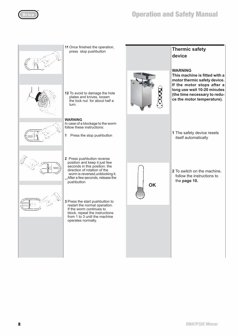
Thermic safety device
WARNINGThis machine is fi tted with a motor thermic safety device. If the motor stops after a long use wait 10-20 minutes (the time necessary to redu-ce the motor temperature).
1 The safety device resets itself automatically
2 To switch on the machine, follow the instructions to the page 10.
11 Once fi nished the operation, press stop pushbutton
12 To avoid to damage the hole plates and knives, loosen the lock nut for about half a turn.
WARNINGIn case of a blockage to the worm follow these instructions:
1 Press the stop pushbutton
2 Press pushbutton reverse position and keep it just few seconds in this position: the direction of rotation of the worm is reversed,unblocking it.
After a few seconds, release the pushbutton
3 Press the start pushbutton to restart the normal operation. If the worm continues to block, repeat the instructions from 1 to 3 until the machine operates normally.
Parte 7 Parte 8
12 13
OK
Dispositivo di sicurezza termico
ATTENZIONEQuesta macchina é dotata di protezione termica al motore. Se durante un uso particolarmente intenso il motore si arresta attendere 10-20 minuti (il tempo neces-sario per ridurre la tempera-tura del nucleo del motore).
1 Il dispositivo di sicurezza, si ripristina automatica- mente.
2 Per avviare la macchina, seguire la descrizione della pag. 10.
11 Terminata la lavorazione, premere il pulsante stop
12 Per non danneggiare le piastre e i coltelli, allentare la ghiera di circa mezzo giro.
ATTENZIONEIn caso di blocco dell’elica, ese-guire le operazioni seguenti:
1 Premere il pulsante stop.
2 Premere il pulsante di inver- sione di marcia, mantenerlo premuto solo per alcuni se- condi: l’elica di lavoro inverte il senso di rotazione, sbloccan- dosi. Rilasciare il pulsante dopo pochi secondi.
3 Premere il pulsante di start per riprendere il normale lavoro. Nel caso l’elica si ribloccasse, ripetere le operazioni dei punti 1-3, fi nché la macchina non fun- ziona regolarmente.
Part 7 Part 8
Thermic safety device
WARNINGThis machine is fi tted with a motor thermic safety device. If the motor stops after a long use wait 10-20 minutes (the time necessary to redu-ce the motor temperature).
1 The safety device resets itself automatically
2 To switch on the machine, follow the instructions to the page 10.
11 Once fi nished the operation, press stop pushbutton
12 To avoid to damage the hole plates and knives, loosen the lock nut for about half a turn.
WARNINGIn case of a blockage to the worm follow these instructions:
1 Press the stop pushbutton
2 Press pushbutton reverse position and keep it just few seconds in this position: the direction of rotation of the worm is reversed,unblocking it.
After a few seconds, release the pushbutton
3 Press the start pushbutton to restart the normal operation. If the worm continues to block, repeat the instructions from 1 to 3 until the machine operates normally.
Operation and Safety Manual™
OMATP32E Mincer 9
Parte 7
10 15
Gli operatori non devono indos-sare indumenti svolazzanti o maniche aperte.
Durante il funzionamento non ci devono essere persone estranee nelle vicinanze del tritacarne.
L’uso della macchina é consentito solo agli operatori che seguono le istruzioni contenute in questo manuale.
Si possono utilizzare piastre con fori di diametro superiore a 8 mm, solo se la macchina é provvista di apposito dispositivo di sicurezza.
ATTENZIONE: LO SPESSORE DELLE PIASTRE, UTILIZZATE VERSO L’APERTURA DI SCA-RICO, NON DEVE ESSERE INFERIORE A 5mm.
ATTENZIONE: NON RIMUOVE-RE LA PIASTRA DI PROTEZIO-NE DELL’APERTURA DI ALI-MENTAZIONE DEL CANOTTO
ATTENZIONE: NON INTRODUR-RE CORPI ESTRANEI NELLA APERTURA DI ALIMENTAZIO-NE DEL CANOTTO.
Funzionamento e uso della macchinaI tritacarne macinano ogni tipo di carne, purché sia disossata e non congelata.Per ottenere una corretta maci-nazione , la carne deve avere una temperatura compresa trai 2 e 5 gradi Centigradi.
1 Assicurarsi che la macchina sia spenta
2 Collegare la macchina alla presa di corrente, controllare la di presa di terra.
3 Preparare la carne nelle di- mensioni adatte per l’inseri- mento nell’apertura di alimentazione del canotto.
4 Appoggiare la carne nella tra- moggia.
Parte 9
Rimozione componenti1 Svitare la ghiera, girandola in senso antiorario.
2a Togliere il distanziale (solo macchine a 2 o 3 passaggi)
2b Togliere piastre e coltelli.
3 Prendere con due mani l’elica di lavoro e sfi larla dal canotto
4 Ruotare, in senso orario sino a fi ne corsa, l’impu- gnatura di bloccaggio del gruppo taglio.
5 Estrarre il canotto
6 Immergere le singole parti in un contenitore di acqua calda con l’aggiunta di un comune detersivo per stovi- glie (evitare detergenti aggressivi che possono danneggiare le parti in alluminio del gruppo taglio).
7 Usare, se necessario uno scovolino a setole per ri- muovere i residui di sporco dalla elica di lavoro, dalla piastra, dal coltello e all’interno del canotto.
8 Sciacquare le parti in acqua corrente ed asciugarle.
ATTENZIONE: Occorre pre-stare particolare attenzione nel pulire l’interno dell’allog-giamento del canotto sul cor-po macchina. E’ possibile che, durante la lavorazione, si depositino dei residui di carne che devono essere rimossi, usare lo scovolino e un canovaccio.
Part 7
No strangers should be near the machine while it is working.
Any person in the proximity of the machine should not wear loose clothes or open sleeves.
Only personnel who have to follow the instructions contained in this manual are authorised to use the machine.
Use perforated discs with holes of more than 8 mm diametre only if the machine is provided with an additional discharge guard.
WARNING: THE THICKNESS OF THE PLATES USED TO-WARDS THE MEAT OUTPUT MUST NOT BE INFERIOR TO 5 mm.
WARNING: DO NOT REMOVE THE RESTRICTOR PLATE OF THE WORM CASING
WARNING: DO NOT INSERT FOREIGN THINGS INTO THE FEED INTAKE OF THE WORM CASING.
Machine funtioning and useThe meat mincers mince any sort of meat provided that it is deboned and defro-sted. For correct mincing the temperature of the meat must be between 2° (35,6 °F) and 5° C (41 °F)
1 Check that the machine is off.
2 Connect the plug and check that the electric supply is con- nected to a suitable earth.
3 Cut the meat to a size suitable to be inserted into the worm hopper.
4 Place the meat in the hopper.
Part 9
Components removal1 Unscrew the lock nut by turning it counterclockwise
2a Remove the space ring (only on machines whit double-triple cut)
2bRemove holes plate and knives.
3 Take the worm with both your hands and insert it on the worm casing
4 Turn the locking screw of the cutting unit in a clockwise direction to the end of the stroke.
5 Remove the worm casing.
6 Leave all the parts to soak in a container with water and washing-up liquid (do not use strong detergents that could damage the aluminium components of the cutting unit).
7 If necessary use a small bristle brush to remove the residual products from the feed worm, the hole plate, the knife and the inside of the worm casing.
8 Rinse the components in run ning water and then dry them.
WARNING: Particular atten-tion must be paid to cleaning the internal housing connec-ting the worm casing with the body of the machine. It is possible that, during the use, meat residues can be depo-sited: these must be remo-ved by using a brush and a cloth.
Parte 7
14 11
5 Preparare, all’uscita del grup- po taglio, un contenitore per la raccolta del prodotto macinato.
6 Prima di macinare la carne avvitare bene la ghiera
ATTENZIONE: La ghiera deve essere avvitata con una coppia massima di serraggio di 7 Kgm
7 Premere il pulsante start per avviare la macchina
8 Il perno dell’elica ruota in senso antiorario, la carne macinata esce dalla piastra
9 Con l’aiuto del pestello, spin- gere la carne all’interno dell’apertura di alimentazione del canotto.
La macchina ha in dotazione un pestello con diametro uguale al foro dell’apertura di alimentazione, per agevolare il pressaggio della merce.
10 Inserire il pestello nella cava ricavata nella piastra di protezione, premere la merce all’interno dell’aper- tura di alimentazione del canotto.
Le dimensioni del prodotto maci-nato dipendono dal tipo di piastra montata.
ATTENZIONEUSARE ESCLUSIVAMENTE IL PESTELLO IN DOTAZIONE: L’IMPIEGO DI ALTRI ATTREZZI PUO’ DANNEGGIARE SERIA-MENTE LA MACCHINA.
ATTENZIONENELL’INTRODURRE LA CARNE NELL’ APERTURA DI ALIMEN-TAZIONE, EVITARE UNA PRES-SIONE ECCESSIVA CHE PUO’ CAUSARE L’ARRESTO DELLA MACCHINA (pag. 13).
Parte 10
PuliziaLa pulizia della macchina va eseguita almeno una volta al giorno, se necessario con maggior frequenza.Per la pulizia di tutte le parti accessibili utilizzare un panno inumidito con acqua e detersivo per stoviglie (non aggressivo), eventualmente utilizzare uno scovolino di setole.
Ricambi
In caso di sostituzione di pezzi richiedere esclusivamente ricambi originali.
C o n t r o l l o c a v o d i alimentazione
Control lare periodicamente lo stato di usura del cavo di alimentazione.
Consigliamo l’uso di guanti protettivi durante le operazione di manutenzione e pulizia.
Prima di eseguire le operazione di pulizia e manutenzione è necessario scollegare la macchina dalla fonte di energia.
Manutenzione
ATTENZIONE Non utilizzare getti d’acquaMessa Fuori Servizio e SmaltimentoIl simbolo apposto sulla macchina indica il divieto di smaltimento con i rifi uti solidi urbani.La Direttiva Europea 2002/96/CE classifi ca la macchina come RAEE, lo smaltimento deve avvenire a norma di legge.
Part 75 Place a foodholding plate under the hole plate outlet to collect the minced meat.
6 Before grinding the meat ca- refully fasten the locking nut.
WARNING: The nut must be to screw with a couple to lock of7 Kgm.
7 Press the start pushbutton to switch on the machine
8 The worm shaft rotates counterclock wise, the minced meat comes out of the hole plate
9 Using the pusher supplied with the machine push the meat to- wards the worm hopper.
The machine is fitted with a pusher, having the same diameter of the feed intake opening, in order to expedite the pressure on the whole product.
10 Insert the pusher into the hole on the restrictor plate, push the meat into the feed intake.
The size of the product to be min-ced depends on the type of hole plate fi tted.
WARNINGONLY USE THE PUSHER SUP-PLIED WITH THE MACHINE. THE USE OF ANY OTHER TO-OLS MAY SERIOUSLY DAMAGE THE MACHINE.
WHEN INTRODUCING THE MEAT INTO THE WORM HOP-PER AVOID USING EXCESSI-VE PRESSURE WHICH MAY CAUSE THE MACHINE STOP (page 13).
Part 10
CleaningThe machine must be cleaned once a day or more frequently if necessary.
Clean all the parts using a cloth sprinkled with water and washing up liquid (do not use strong detergents) and a brush
Spare parts
In the event that replacement parts need to be fi tted, request only original spare parts.
Check of the electric cable
It is recommended to check the wear of the electric cable at regular intervals.
All cleaning and maintenance operations must be carried out whilst wearing protective gloves.
All cleaning and maintenance opera t ions mus t on ly be carried out with the machine disconnected and isolated from the mains supply.
Maintenance
WARNINGDo not use water jetRemoval and disposalThe symbol aff ixed on the machine means that it must not be disposed with usual urban waste.The European 2002/96/EC Directive classifi es the machine as WEEE, which disposal must be effected according to law.
Operation and Safety Manual™
OMATP32E Mincer10
Parte 6
8 17
5 Premere il pulsante stop
6 Scollegare la macchina dalla presa di corrente
IMPORTANTEPulizia preliminare: termi-nato il controllo del senso di rotazione, pulire la macchina dall’olio di protezione.Riassemblare i componenti seguendo le istruzioni nella page 17.
Parte 9
Montaggio gruppo taglio a 2-3 passaggi1 Ruotare, in senso orario sino a fi ne corsa, l’impu- gnatura di bloccaggio del gruppo taglio.
2 Tenere il canotto con due mani, appoggiarlo al corpo macchina e spingerlo a fondo nella propria sede.
3 Ruotare in senso antiorario, l’impugnatura di bloccaggio sino ad ottenere il blocco del canotto.
4 Prendere con due mani l’elica di lavoro ed infi larla nel canotto
5 Assicurarsi che la sede quadrata dell’elica di lavoro coincida con il perno qua- drato di trascinamento, infi lare l’ elica di lavoro all’interno del canotto.
6 Montare la prima piastra (sgrossatrice) infi landola sul perno dell’elica, facen- do attenzione che la parte tagliente dei fori sia verso l’esterno.
7 Montare il coltello a doppio tagliente sul perno dell’elica con il codolo rivolto verso l’esterno.
ATTENZIONE: IL CODO-LO DEL COLTELLO DEVE ES-SERE RIVOLTO VERSO L’ESTERNO. PERICOLO DI GRAVE DANNEGGIAMEN-TO ALLA MACCHINA SE IL COLTELLO VIENE MONTA-TO AL CONTRARIO (CODO-LO VERSO L’INTERNO).
8 Montare la seconda piastra, infi landola sul codolo del coltello e facendo coincide- re la tacca con la spina di riferimento del canotto.
IMPORTANTE: Nel caso di gruppo taglio a 2 passaggi, proseguire dal punto 11
Part 6
5 Press the stop pushbutton
6 Disconnected the machine from the electric supply.
IMPORTANTEPreliminary cleaning: oncechecked the rotation direc-tion, clean the machine, by removing the protecting oil.Reassemble the components, by following the instructions given on pag.17.
Part 9
Assembling 2-3 cut cutting unit1 Turn clockwise the handle of the cutting unit to the end of the stroke.
2 With both your hands in- sert the worm casing into the machine and push it in.
3 Turn counterclockwisethe handle of the cutting unit to lock the worm casing.
4 With both your hands insert the worm into the worm casing
5 Making sure that the square drive on the worm seats is positioned on the drive pin, insert the worm into the worm casing.
6 Fit the fi rst hole plate (large hole plate) inserting it into the worm shaft. Make sure that the cutting side of the holes are pointing outwards.
7 Fitt the double edged knives on the worm shaft with the tang pointing outwards.
ATTENTION: THE TANG ON THE KNIVES MUST POINT OUTWARDS. THERE IS A RISK THAT THE MACHINE MAY BE DAMAGED IF THE KNIVES ARE FITTED THE OTHER WAY ROUND (TANG INWARDS).
8 Fitt the second hole plate inserting it on the tang of the knife ensuring that the notch is aligned with the reference pin on the worm casing.
IMPORTANTIn case of double cutting set,continue from point 11.
16 9
Parte 7
Descrizione macchinaIl tritacarne si distingue per l’ac-curata scelta dei materiali che lo rendono particolarmente robusto. Semplicità di linee e assenza di spigoli, conferiscono funzionalità e praticità nella pulizia e nell’uso del tritacarne. Scelta accurata dei materiali nel rispetto delle norma-tive igienico sanitarie.
-L’elevata potenza del motore, consente un’alta quantità di pro-duzione.
-Nel motore é inserito un disposi-tivo di sicurezza termico, di prote-zione contro le sovratemperature.
- Pulsante di reverse instabile(1a): premendo il pulsante si in-verte il senso di rotazione, al suo rilascio si arresta la rotazione, comando utilizzabile in caso di blocco dell’elica di lavoro.
-Il pestello é costruito in polietile-ne o acciaio INOX, amteriali adatti per il contatto con gli alimenti.
-La parte terminale del gruppotaglio é fornita di un fi letto ar-rotondato Edison, secondo la Normativa NSF standard 8.
-La semplicità delle operazionidi smontaggio e assemblaggio dei componenti consentono una estrema facilità d’ uso.
In mancanza della tensione di rete, la macchina si arresta. Attendere il ritorno della tensione di rete per riavviare la macchina.
Non manomettere le etichette collocate sulla macchina: in caso di danneggiamento sostituirle.
Montaggio gruppo taglio a 1 passaggio9 Ruotare, in senso orario sino a fi ne corsa, l’impu- gnatura di bloccaggio del gruppo taglio.
10 Tenere il canotto con due mani, appoggiarlo al corpo macchina e spingerlo a fondo nella propria sede.
11 Ruotare in senso antiora- rio, l’impugnatura di bloc- caggio sino ad ottenere il blocco del canotto.
12 Prendere con due mani l’elica di lavoro ed infi larla nel canotto.
13 Assicurandosi che la sede quadrata dell’elica di lavoro coincida con il perno qua- drato di trascinamento, infi lare l’ elica di lavoro all’interno del canotto.
14 Montare il coltello sul perno dell’elica di lavoro inserendolo nella sede quadrata, con i taglienti rivolti verso l’esterno.
ATTENZIONE: I TAGLIENTI DEL COLTELLO DEVONO ESSERE RIVOLTI VERSO L’ESTERNO. PERICOLO DI GRAVE DANNEGGIA-MENTO ALLA MACCHINA SE IL COLTELLO VIENE MONTATO AL CONTRARIO (TAGLIENTI VERSO L’IN-TERNO).
15 Montare la piastra, infi lan- dola sul perno dell’elica e facendo coincidere la tacca con la spina di riferi- mento del canotto.
16 Montare la ghiera, avvitan- dola in senso orario.
Parte 9
230 V
400 V
1a
STOP
Part 7
Machine descriptionThe mincer is made of selected materials that make the machine particularly robust.Simple design with smooth parts without sharp edges provide for easy cleaning and a practical use of the machine.Careful choice of the materials ac-cording to the health and hygiene standards.
-The high motor power provides high production capacity.
-The motor is fi tted with a thermic safety device as a protection against excess temperature
- Pulsante di reverse instabile (1a): premendo il pulsante si inverte il senso di rotazione, al suo rilascio si arresta la rotazione, coman-do utilizzabile in caso di blocco dell’elica di lavoro.
-The pusher is made in polyethyle-ne or INOX, material fi t for contact with foodstuffs.
-The fi nal part of the cutting unit is fi tted with an EDISON screw thread according to the NSF standard 8.
-The easy assembly and disas-sembly of the components simplify the use of the machine.
In case of power failure, the ma-chine stops. Wait the return of the power, to restart the machine.
Do not remove the labels placed on the machine; if damaged, they must be replaced.
Part 9
Assembling 1 cut cut-ting unit 9 Turn clockwise the handle of the cutting unit to the end of the stroke.
10 With both your hands in- sert the worm casing into the machine and push it in.
11 Turn counterclockwisethe handle of the cutting unit to lock the worm casing.
12 With both your hands in- sert the worm into the worm casing
13 Making sure that the square drive on the worm seats is positioned on the drive pin, insert the worm into the worm casing.
14 Mount the blades on the feed screw shaft by inserting them onto the square seat with the cutting edges pointing outwards.
ATTENTION: THE CUTTING EDGES OF THE KNIVES MUST BE POSITIONED TO-WARDS THE OUTSIDE.THE MACHINE CAN BE DAMAGED IF THE KNIVES ARE MOUNTED IN THE OP-POSITE POSITION (CUT-TING EDGES POINTING TOWARDS THE INSIDE).
15Mount the hole plate by inserting it on the worm shaft and by ensuring that the notch is aligned with the reference pin on the worm casing.
16 Mount the nut and turning it in a clockwise direction.
Operation and Safety Manual™
OMATP32E Mincer 11
Parte 6
6 19
Installazione
La collocazione della macchi-na deve essere effettuato da due persone.
Il tritacarne deve essere collo-cato su una superfi cie piana orizzontale e antiscivolo.
Prima di utilizzare la macchina, bloccare le ruote posteriori.
Allacciamento elettricoLa macchina deve essere installata vicino ad una presa di corrente. Controllare che la tensione corrisponda ai dati di targa e che la presa sia corredata di messa a terra.
Controllo senso di rotazione
IMPORTANTEEseguire il controllo del senso di rotazione, solo per le macchine con motore trifase.
PERICOLO: I componenti del gruppo taglio si possono seriamente danneggiare se il senso di rotazione dell’elica di lavoro non é corretto.
1 Seguire le istruzioni descritte nella pag. 18 “Operazione di rimozione gruppo taglio completo”
Parte 9
Operazione di montag-gio gruppo taglio com-pleto
Ruotare, in senso orario sino a fi ne corsa, l’impu-gnatura di bloccaggio delgruppo taglio.
Tenendo il canotto con due mani, appoggiarlo alla macchina facendo coin-cidere i bordi sporgenti delcanotto con quelli della macchina, e infilarlo nel corpo macchina.Assicurandosi che la sede quadrata dell’elica di lavoro coincida con il perno qua-drato di trascinamento, accostare il gruppo taglio al corpo macchina.
Ruotare, in senso antiora-rio,l’impugnatura di bloc-caggio sino ad ottenere ilblocco del canotto.
Avvitare la ghiera in sensoorario.
Montaggio tramoggia
Collocare il piatto raccogli-tore sotto il gruppo taglio.
6
7
8
9
10
11
12
Part 6
Installation
The machine must be carried by two operators.
The mincer must be placed horizontally and antiskid.
Block the rear wheels before starting using the machine.
Electrical supplyThe machine must be installed near to a main socket.Check that the power supply voltage corresponds to that described on the information label and that it is connected to an adequate earth.
Check the rotation direction
IMPORTANTCheck the rotation direc-tion, only on the machines fi tted with a 3-phase motor.
DANGER: The components of the cutting set can be seriously damaged if the ro-tation direction of the worm is not the correct one.
1 Follow the instruction of page 18 “Disassembling of the complete cutting unit”
Part 9
Assembling of the complete cutting unit
6
7
8
9
10
11
12
Turn the locking screw of the cutting unit clockwise to the end of the stroke.
With both your hands insert the worm casing into the machine positioning the edges of the worm casing on those of the machine and push it.
By making sure that the square drive on the worm seat is positioned on the square drive pin offer up the cutting unit to the body of the machine.
Turn the worm casing locking screw counter-clockwise to lock the ca-sing.
Turn the lock nut in a clockwise direction.
Hopper assembling
Place the foodholding plateunder the cutting unit.
Parte 6
18 7
2 Collegare la macchina alla presa di corrente
3 Premere il pulsante di start per avviare la macchina
IMPORTANTECONTROLLARE CHE IL PERNO QUADRATO RUOTI IN SENSO ANTIORARIO.IN CASO CONTRARIO FER-MARE LA MACCHINA.
TOGLIERE LA SPINA DAL-LA PRESA DI CORRENTE E INVERTIRE DUE FILI NELLA SPINA.
SE LA MACCHINA E’ DO-TATA DI UNA SPINA CON INVERTITORE DI FASE INCORPORATO, UTILIZ-ZANDO UN CACCIAVITE PREMERE E RUOTARE DI 180° PER OTTENERE L’IN-VERSIONE AUTOMATICA DELLE FASI.
PERICOLOLA MACCHINA DEVE FUN-ZIONARE SOLO SE IL SEN-SO DI ROTAZIONE E’ COR-RETTO.
Parte 99 Montare il secondo coltello a doppio tagliente sul per- no dell’elica con il codolo rivolto verso l’esterno.
ATTENZIONE: IL CODO-LO DEL COLTELLO DEVE ES-SERE RIVOLTO VERSO L’ESTERNO. PERICOLO DI GRAVE DANNEGGIAMENTO ALLA MACCHINA SE IL COL-TELLO VIENE MONTATO AL CONTRARIO (CODOLO VERSO L’INTERNO).
10 Montare la terza piastra, infi landola sul codolo del coltello e facendo coinci- dere la tacca con la spina di riferimento del canotto.
11 Montare il distanziale, fa- cendo coincidere la tacca con la spina di riferimento del canotto.
12 Montare la ghiera, avvitan- dola in senso orario.
Collocare la tramoggia e il piatto raccoglitore come indicato nella pag. 20.
Operazione di smon-taggio gruppo taglio completoData la particolare conforma-zione di costruzione, vi é la possibilità, in caso ecceziona-le, di riporre in frigo il gruppo taglio.
1 Sfi lare la tramoggia dal canotto
2 Allentare la ghiera, ruotan- dola in senso antiorario.
3 Ruotare, in senso orario sino a fi ne corsa, l’impugna- tura di bloccaggio del gruppo taglio.
4 Estrarre il gruppo taglio.
5 Riporre il gruppo taglio completo in frigorifero.
Part 6
2 Connect the plug at the electric supply.
3 Press start pushbutton to switch on the machine
IMPORTANTTHE SQUARE SHAFT MUST TURN ANTICLOCKWISE. SHOULD IT TURN CLOCK-WISE, STOP THE MACHINE.
DISCONNECTED THE PLUG FROM THE POWER SUPPLY AND REVERSE THE WIRES IN THE PLUG.
I F T H E M A C H I N E I S F ITTED WITH A PLUG WITH SELF-CONTAINED PHASE INVERTER, USE A SCREW-DRIVER INSIDE THE PLUG, TO ROTATE BY 180° THE AUTOMATIC PHASE INVERTER.
DANGERTHE MACHINE MUST RUN ONLY IF THE ROTATION IS CORRECT.
Part 99 Fit the second double ed- ged knife on the worm shaft with the tang pointing outwards.
ATTENTION: THE TANG ON THE KNIVES MUST POINT OUTWARDS. THERE IS A RISK THAT THE MACHINE MAY BE DAMAGED IF THE KNIVES ARE FITTED THE OTHER WAY ROUND (TANG INWARDS).
10Fit the third hole plate inser- ting it on the tang of the knife ensuring that the notch is aligned with the referen- ce pin on the worm casing.
11 Fit the spacer ensuring that the notch is aligned with the reference pin on the worm casing.
12Fit the lock nut and turning it in a clockwise direction.
Fit the tray and the foodhol-ding plate as indicate under page 20.
Disassembling of the complete cutting unit
Due to the particular construc-tion of the cutting unit it is possible, in exceptional cir-cumstances, to place it in a refrigerator.
1 Lift up the tray from the worm casing
2 Unscrew the nut by turning it counterclockwise.
3 Turn the locking screw of the cutting unit clockwise to the end of the stroke.
4 Remove the cutting unit.
5 Place the complete cutting unit in the fridge.
Operation and Safety Manual™
OMATP32E Mincer12
Parte 5
20
Caratteristiche tecniche
Caratteristichemotore
W HzV
1800 1~
3000 400 3~
N°.
Fasi
Phas
e N
°.
50
CL
Col
lega
men
ti
Serv
izio
Serv
ice
Con
nect
ion
nmin
1
2
3
4
5
6
7
Dimensioni (mm)
Peso Kg
Senza imballo
Con imballo
Temperatura di utilizzo
Rumorosita’ dB
Grado di protezione impianto elettrico e comandi
5
1
2
3
4
5
6
7
1450 B S1
1
TP 32E
A 800B 550C 430D 1100 E 460F 670 127 145
+5 °C ÷ +40 °C<70
IP 65
567
234
Parte 10
Nel caso le soluzioni proposte non risolvono l’anomalie indi-cate, interpellare l’assistenza.
ANOMALIALa macchina vibra, surriscalda, emana un cattivo odore
SoluzioneFermare la macchina e controllare che la tensione corrisponda ai dati di targa (pag. 5)
ANOMALIALa carne é lavorata in modo irregolare.
SoluzioneControllare che il gruppo taglio é montato correttamente (pag. 17).Controllare se le piastre e i coltelli sono usurate, in questo caso sostituire i componenti.
ANOMALIAIl perno dell’ elica é partico-larmente usurato.
SoluzioneChiamare l’Assistenza per la sostituzione.
230
Part 5
Technical dataDimensions (mm)
Weight Kg
Without packaging
With packaging
Range temperature
Acoustic dB
Protection grade of the electrical system and switches
Motorsdata
Part 10
In the event of any faulty operation do not hesitate to contact the customer service.
PROBLEMThe mach ine v ib ra tes , overheats and emits a foul smell
Corrective actionStop it and check that the voltage meets the one given on the metal plate (page 5)
PROBLEMthe meat comes out not correctly
Corrective actionCheck the correct assembly of the cutting set (page 17).Check the wear of the hole plates and knives, if these are worn, replace them.
PROBLEMThe worm shaft is badly worn.
Corrective actionContact Customer Service to replace it.
2
Parte 2
IndiceDESCRIZIONE
1
2
3
4
5
6
9
13
14
20
21
Parte 1
Parte 2Indice
Parte 3Note generali alla consegnaCondizioni di fornituraIdentifi cazione della macchina
Parte 4Defi nizione componenti
Parte 5Caratteristiche tecniche
Parte 6InstallazioneAllacciamento elettricoControllo senso di rotazione con motore monofase
Parte 7Descrizione macchina Funzionamento e uso della macchina
Parte 8Dispositivo di sicurezza termico
Parte 9ManutenzionePuliziaRimozione componentiMontaggio gruppo taglio a 1 passaggioMontaggio gruppo taglio a 2-3 passaggiOperazione di smontaggio gruppo taglio completoOperazione di montaggio gruppo taglio completo
Parte 10Anomalie e soluzioni
Schemi Elettrici
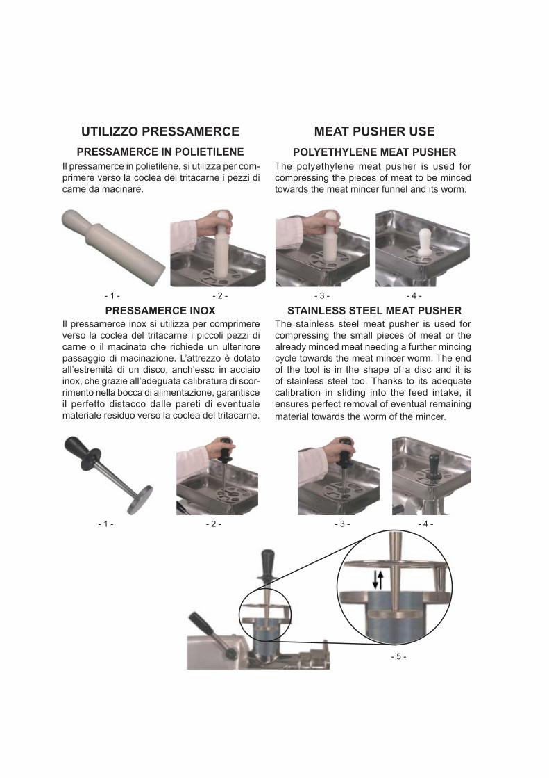
PRESSAMERCE IN POLIETILENE
PRESSAMERCE INOXIl pressamerce inox si utilizza per comprimere verso la coclea del tritacarne i piccoli pezzi di carne o il macinato che richiede un ulterirore passaggio di macinazione. L’attrezzo è dotato all’estremità di un disco, anch’esso in acciaio inox, che grazie all’adeguata calibratura di scor-rimento nella bocca di alimentazione, garantisce il perfetto distacco dalle pareti di eventuale materiale residuo verso la coclea del tritacarne.
Il pressamerce in polietilene, si utilizza per com-primere verso la coclea del tritacarne i pezzi di carne da macinare.
- 1 - - 2 - - 3 - - 4 -
POLYETHYLENE MEAT PUSHERThe polyethylene meat pusher is used for compressing the pieces of meat to be minced towards the meat mincer funnel and its worm.
STAINLESS STEEL MEAT PUSHERThe stainless steel meat pusher is used for compressing the small pieces of meat or the already minced meat needing a further mincing cycle towards the meat mincer worm. The end of the tool is in the shape of a disc and it is of stainless steel too. Thanks to its adequate calibration in sliding into the feed intake, it ensures perfect removal of eventual remaining material towards the worm of the mincer.
UTILIZZO PRESSAMERCE MEAT PUSHER USE
- 1 - - 2 - - 3 - - 4 -
- 5 -
Part 1
Part 2 Index
Part 3 General delivery conditionsDelivery conditionsMachine identifi cation
Part 4 Defi nitions
Part 5 Technical data
Part 6InstallationElectrical supplyCheck the rotation directionwith single phase motor
Part 7Machine descriptionMachine use and operation
Part 8 Thermic safety device
Part 9MaintenanceCleaningComponents removalAssembling 1 cut cutting unitAssembling 2-3 cut cutting unit Disassembling of the complete cutting unit Assembling of the complete cutting unit
Part 10 Problems and corrective actions
Electric Diagram
ContentsDESCRIPTION
Part 2


Copyright InformationCopyright © 2013 Brice Australia Pty. Ltd.
This document may not be reproduced, in whole or in part, by any means without the prior express written permission of the copyright owner.
Brice and the BRICE logotype are trademarks of Brice Australia Pty. Ltd.
Printed in Australia
BA350 OMATP32E 5/13


![[italiano] - Stabilizzatori - KERT · La ringraziamo per la scelta di questo prodotto. ... Estrarre il gruppo dalla confezione e liberarlo dell’imballo. 2. Il gruppo deve essere](https://static.fdocumenti.com/doc/165x107/5c701e8109d3f2dc7b8c7354/italiano-stabilizzatori-kert-la-ringraziamo-per-la-scelta-di-questo-prodotto.jpg)