MOTOR HOLDING S.p.A. DUCATIPERFORMANCE
7
Cod. ISTR - 202 Pag. 1/7 Modelli di riferimento: / Reference Ducati Motorcycles: I particolari con riferimento cerchiato rappresentano l’accessorio da installare e gli eventuali componenti di montaggio. Quelli non cerchiati si riferiscono ai componenti originali che devono essere riutilizzati. Per una lettura rapida e razionale sono stati impiegati simboli che evidenziano situazioni di massima attenzione, consigli pratici o semplici informazioni. Tutte le indicazioni destro o sinistro si riferiscono al senso di marcia del motociclo. Part nos. that are circled represent the accessory to be installed and possible relevant fittings. Part nos. that are not circled refer to original parts to be re-used. For easy and rational reading, this document uses graphic symbols for highlighting situations in which maximum care is required, practical advice or simple information. Any right- or left-hand indication refers to the vehicle direction of travel. Attenzione/Warning La non osservanza delle istruzioni riportate può creare una situazione di pericolo e causare gravi lesioni personali e anche la morte. Failure to follow these instructions might give raise to a dangerous situation and provoke severe personal injuries or even death. Importante/Caution Indica la possibilità di arrecare danno al veicolo e/o ai suoi componenti se le istruzioni riportate non vengono eseguite. Failure to follow these instructions might cause damages to the vehicle and/or its components. Note/Note Fornisce utili informazioni sull'operazione in corso. Useful information on the procedure being described. I particolari riquadrati si riferiscono a particolari da eliminare. Boxed items must be removed permanently. DUCATIPERFORMANCE DUCATI MOTOR HOLDING S.p.A. Monster S4RS Kit scarico completo / Complete exhaust kit - 96448506B Kit silenziatori laterali alti / Raised side silencers kit - 96448606B - 96448606BC 1 Filtro aria 2 Centralina accensione / iniezione 3 Gruppo silenziatori / staffa 4 Gruppo tubi scarico intermedi / protezioni 5 Gruppo compensatore 5A Sonda lambda 6 Gruppo tubo scarico testa verticale 7 Gruppo di fissaggio 8 Dado 1 Air filter 2 Ignition / injection control unit 3 Bracket/silencers unit 4 Protections / intermediate exhaust pipes assembly 5 Collector box unit 5A Lambda sensor 6 Vertical exhaust pipe unit 7 Fasteners 8 Nut 8 8 3 4 2 5 7 6 1 5A
Transcript of MOTOR HOLDING S.p.A. DUCATIPERFORMANCE
Modelli di riferimento: / Reference Ducati Motorcycles:
DUCATIPERFORMANCEDUCATI MOTOR HOLDING S.p.A.
Monster S4RS
Kit scarico completo / Complete exhaust kit - 96448506BKit silenziatori laterali alti / Raised side silencers kit - 96448606B - 96448606BC
8
8
3
4
2
7
6
1
5A
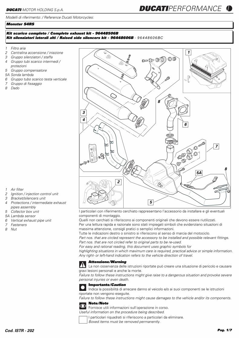
1 Filtro aria2 Centralina accensione / iniezione3 Gruppo silenziatori / staffa4 Gruppo tubi scarico intermedi /
protezioni5 Gruppo compensatore5A Sonda lambda6 Gruppo tubo scarico testa verticale7 Gruppo di fissaggio8 Dado
I particolari con riferimento cerchiato rappresentano l’accessorio da installare e gli eventuali componenti di montaggio.Quelli non cerchiati si riferiscono ai componenti originali che devono essere riutilizzati.Per una lettura rapida e razionale sono stati impiegati simboli che evidenziano situazioni di massima attenzione, consigli pratici o semplici informazioni.Tutte le indicazioni destro o sinistro si riferiscono al senso di marcia del motociclo.Part nos. that are circled represent the accessory to be installed and possible relevant fittings.Part nos. that are not circled refer to original parts to be re-used.For easy and rational reading, this document uses graphic symbols forhighlighting situations in which maximum care is required, practical advice or simple information.Any right- or left-hand indication refers to the vehicle direction of travel.
Attenzione/WarningLa non osservanza delle istruzioni riportate può creare una situazione di pericolo e causare
gravi lesioni personali e anche la morte.Failure to follow these instructions might give raise to a dangerous situation and provoke severe personal injuries or even death.
Importante/CautionIndica la possibilità di arrecare danno al veicolo e/o ai suoi componenti se le istruzioni
riportate non vengono eseguite.Failure to follow these instructions might cause damages to the vehicle and/or its components.
Note/NoteFornisce utili informazioni sull'operazione in corso.
Useful information on the procedure being described.I particolari riquadrati si riferiscono a particolari da eliminare.Boxed items must be removed permanently.
5
1 Air filter2 Ignition / injection control unit 3 Bracket/silencers unit4 Protections / intermediate exhaust
pipes assembly5 Collector box unit 5A Lambda sensor6 Vertical exhaust pipe unit7 Fasteners 8 Nut
Cod. ISTR - 202 Pag. 1/7
DUCATIPERFORMANCE DUCATI MOTOR HOLDING S.p.A.
12
8
1140
18
26
33
41
4230
14
3225 26
29
28
27
17
19
16
18
43
30
31
10
31
25
32
927
29
35
Kit scarico completo / Complete exhaust kit
Kit silenziatori / Silencers kit
33
11
27
34
27
33
24
18
18
3638
37
38
39
15
8
13
20
21
22
23
33
34
27
28
27
24
44
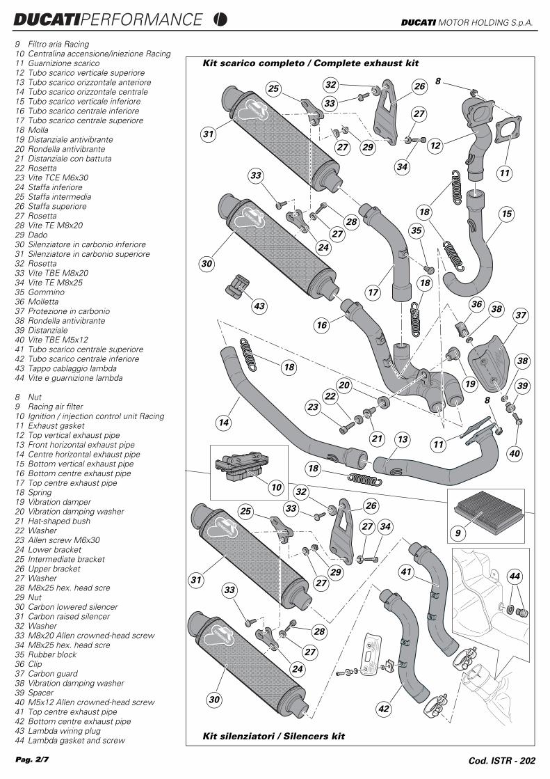
8 Nut9 Racing air filter 10 Ignition / injection control unit Racing11 Exhaust gasket12 Top vertical exhaust pipe13 Front horizontal exhaust pipe14 Centre horizontal exhaust pipe15 Bottom vertical exhaust pipe16 Bottom centre exhaust pipe17 Top centre exhaust pipe18 Spring19 Vibration damper20 Vibration damping washer21 Hat-shaped bush22 Washer23 Allen screw M6x3024 Lower bracket 25 Intermediate bracket 26 Upper bracket 27 Washer28 M8x25 hex. head scre29 Nut 30 Carbon lowered silencer31 Carbon raised silencer32 Washer33 M8x20 Allen crowned-head screw34 M8x25 hex. head scre35 Rubber block36 Clip37 Carbon guard38 Vibration damping washer39 Spacer40 M5x12 Allen crowned-head screw41 Top centre exhaust pipe42 Bottom centre exhaust pipe43 Lambda wiring plug44 Lambda gasket and screw
9 Filtro aria Racing10 Centralina accensione/iniezione Racing11 Guarnizione scarico12 Tubo scarico verticale superiore13 Tubo scarico orizzontale anteriore14 Tubo scarico orizzontale centrale15 Tubo scarico verticale inferiore16 Tubo scarico centrale inferiore17 Tubo scarico centrale superiore18 Molla19 Distanziale antivibrante20 Rondella antivibrante21 Distanziale con battuta22 Rosetta23 Vite TCE M6x3024 Staffa inferiore25 Staffa intermedia26 Staffa superiore27 Rosetta28 Vite TE M8x2029 Dado30 Silenziatore in carbonio inferiore31 Silenziatore in carbonio superiore32 Rosetta33 Vite TBE M8x2034 Vite TE M8x2535 Gommino36 Molletta37 Protezione in carbonio38 Rondella antivibrante39 Distanziale40 Vite TBE M5x1241 Tubo scarico centrale superiore42 Tubo scarico centrale inferiore43 Tappo cablaggio lambda44 Vite e guarnizione lambda
Pag. 2/7 Cod. ISTR - 202
Cod. ISTR - 202
DUCATIPERFORMANCEDUCATI MOTOR HOLDING S.p.A.
NoteRead the attached instructions
carefully before proceeding.
Removing the original components
WarningHave the kit installed by a trained
technician or at a DUCATI Authorized Workshop.
WarningIncorrect installation of this kit may
lead to severe engine damage and put the rider’s safety at risk.
NoteSome of the operations required to
install this kit are described in the Workshop Manual for your motorcycle model (Monster S4RS).
Disassembly Procedure
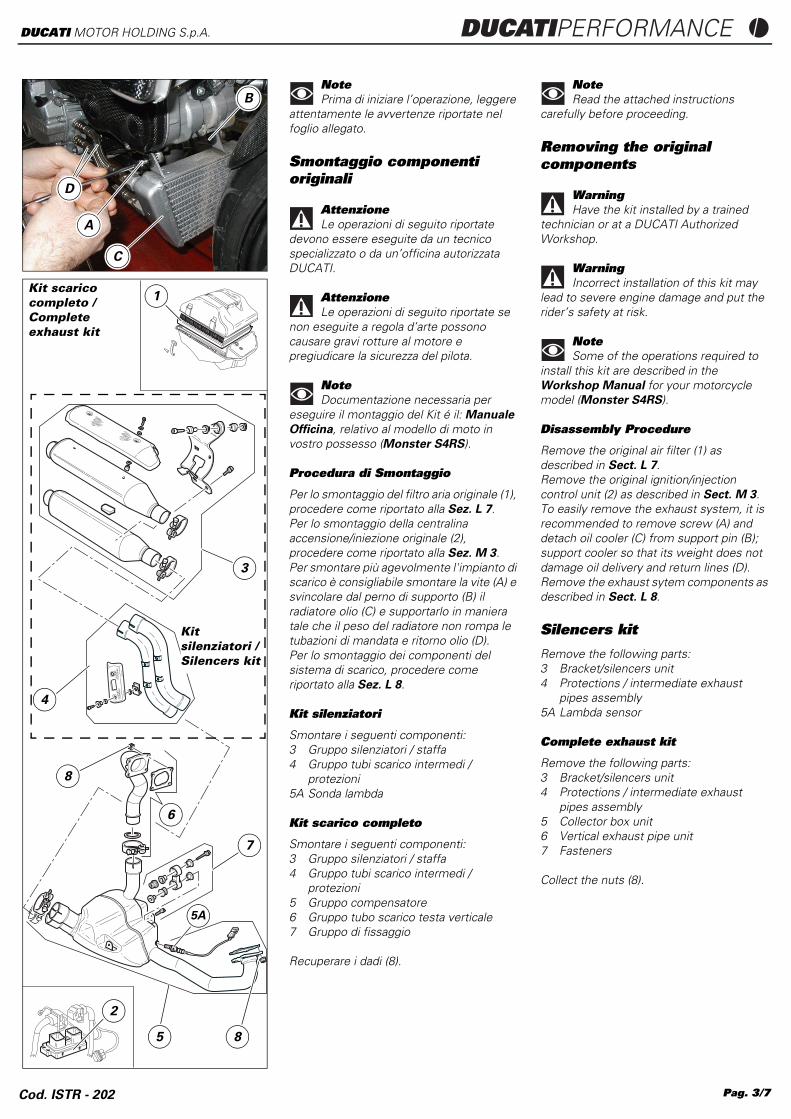
Remove the original air filter (1) as described in Sect. L 7.Remove the original ignition/injection control unit (2) as described in Sect. M 3.To easily remove the exhaust system, it is recommended to remove screw (A) and detach oil cooler (C) from support pin (B); support cooler so that its weight does not damage oil delivery and return lines (D). Remove the exhaust sytem components as described in Sect. L 8.
Silencers kit
Remove the following parts:3 Bracket/silencers unit4 Protections / intermediate exhaust
pipes assembly5A Lambda sensor
Complete exhaust kit
Remove the following parts:3 Bracket/silencers unit4 Protections / intermediate exhaust
pipes assembly5 Collector box unit 6 Vertical exhaust pipe unit7 Fasteners
Collect the nuts (8).
D
A
B
C
1
6
8
7
5
2
4
3
8
Kit scarico completo /Complete exhaust kit
Kit silenziatori /Silencers kit
5A
NotePrima di iniziare l’operazione, leggere
attentamente le avvertenze riportate nel foglio allegato.
Smontaggio componenti originali
AttenzioneLe operazioni di seguito riportate
devono essere eseguite da un tecnico specializzato o da un’officina autorizzata DUCATI.
AttenzioneLe operazioni di seguito riportate se
non eseguite a regola d’arte possono causare gravi rotture al motore e pregiudicare la sicurezza del pilota.
NoteDocumentazione necessaria per
eseguire il montaggio del Kit é il: Manuale
Officina, relativo al modello di moto in vostro possesso (Monster S4RS).
Procedura di Smontaggio
Per lo smontaggio del filtro aria originale (1), procedere come riportato alla Sez. L 7.Per lo smontaggio della centralina accensione/iniezione originale (2), procedere come riportato alla Sez. M 3.Per smontare più agevolmente l'impianto di scarico è consigliabile smontare la vite (A) e svincolare dal perno di supporto (B) il radiatore olio (C) e supportarlo in maniera tale che il peso del radiatore non rompa le tubazioni di mandata e ritorno olio (D). Per lo smontaggio dei componenti del sistema di scarico, procedere come riportato alla Sez. L 8.
Kit silenziatori
Smontare i seguenti componenti:3 Gruppo silenziatori / staffa4 Gruppo tubi scarico intermedi /
protezioni5A Sonda lambda
Kit scarico completo
Smontare i seguenti componenti:3 Gruppo silenziatori / staffa4 Gruppo tubi scarico intermedi /
protezioni5 Gruppo compensatore6 Gruppo tubo scarico testa verticale7 Gruppo di fissaggio
Recuperare i dadi (8).
Pag. 3/7
Pag. 4/7
DUCATIPERFORMANCE DUCATI MOTOR HOLDING S.p.A.
Kit installation
CautionCheck that all components are clean
and in perfect condition before installation.Take adequate measures to avoid damaging the internal components of the engine.
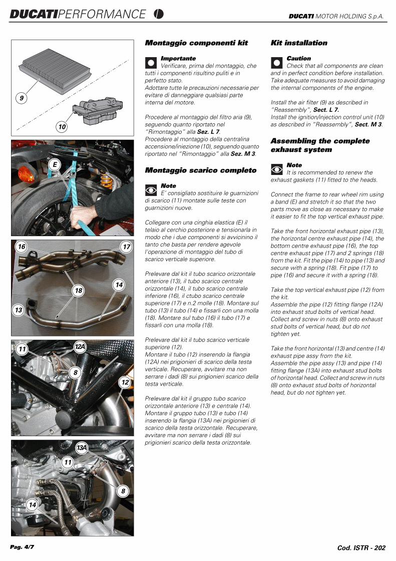
Install the air filter (9) as described in “Reassembly”, Sect. L 7.
Install the ignition/injection control unit (10) as described in “Reassembly”, Sect. M 3.
Assembling the complete exhaust system
NoteIt is recommended to renew the
exhaust gaskets (11) fitted to the heads.
Connect the frame to rear wheel rim using a band (E) and stretch it so that the two parts move as close as necessary to make it easier to fit the top vertical exhaust pipe.
Take the front horizontal exhaust pipe (13), the horizontal centre exhaust pipe (14), the bottom centre exhaust pipe (16), the top centre exhaust pipe (17) and 2 springs (18) from the kit. Fit the pipe (14) to pipe (13) and secure with a spring (18). Fit pipe (17) to pipe (16) and secure it with a spring (18).
Take the top vertical exhaust pipe (12) from the kit.Assemble the pipe (12) fitting flange (12A) into exhaust stud bolts of vertical head. Collect and screw in nuts (8) onto exhaust stud bolts of vertical head, but do not tighten yet.
Take the front horizontal (13) and centre (14) exhaust pipe assy from the kit.Assemble the pipe assy (13) and pipe (14) fitting flange (13A) into exhaust stud bolts of horizontal head. Collect and screw in nuts (8) onto exhaust stud bolts of horizontal head, but do not tighten yet.
9
10
E
16
14
17
18
13
11
12
12A
8
14
8
13A
11
Montaggio componenti kit
ImportanteVerificare, prima del montaggio, che
tutti i componenti risultino puliti e in perfetto stato.Adottare tutte le precauzioni necessarie per evitare di danneggiare qualsiasi parte interna del motore.
Procedere al montaggio del filtro aria (9), seguendo quanto riportato nel “Rimontaggio” alla Sez. L 7.Procedere al montaggio della centralina accensione/iniezione (10), seguendo quanto riportato nel “Rimontaggio” alla Sez. M 3.
Montaggio scarico completo
NoteE’ consigliato sostituire le guarnizioni
di scarico (11) montate sulle teste con guarnizioni nuove.
Collegare con una cinghia elastica (E) il telaio al cerchio posteriore e tensionarla in modo che i due componenti si avvicinino il tanto che basta per rendere agevole l'operazione di montaggio del tubo di scarico verticale superiore.
Prelevare dal kit il tubo scarico orizzontale anteriore (13), il tubo scarico centrale orizzontale (14), il tubo scarico centrale inferiore (16), il ctubo scarico centrale superiore (17) e n.2 molle (18). Montare sul tubo (13) il tubo (14) e fissarli con una molla (18). Montare sul tubo (16) il tubo (17) e fissarli con una molla (18).
Prelevare dal kit il tubo scarico verticale superiore (12).Montare il tubo (12) inserendo la flangia (12A) nei prigionieri di scarico della testa verticale. Recuperare, avvitare ma non serrare i dadi (8) sui prigionieri scarico della testa verticale.
Prelevare dal kit il gruppo tubo scarico orizzontale anteriore (13) e centrale (14).Montare il gruppo tubo (13) e tubo (14) inserendo la flangia (13A) nei prigionieri di scarico della testa orizzontale. Recuperare, avvitare ma non serrare i dadi (8) sui prigionieri scarico della testa orizzontale.
Cod. ISTR - 202
Cod. ISTR - 202
DUCATIPERFORMANCEDUCATI MOTOR HOLDING S.p.A.
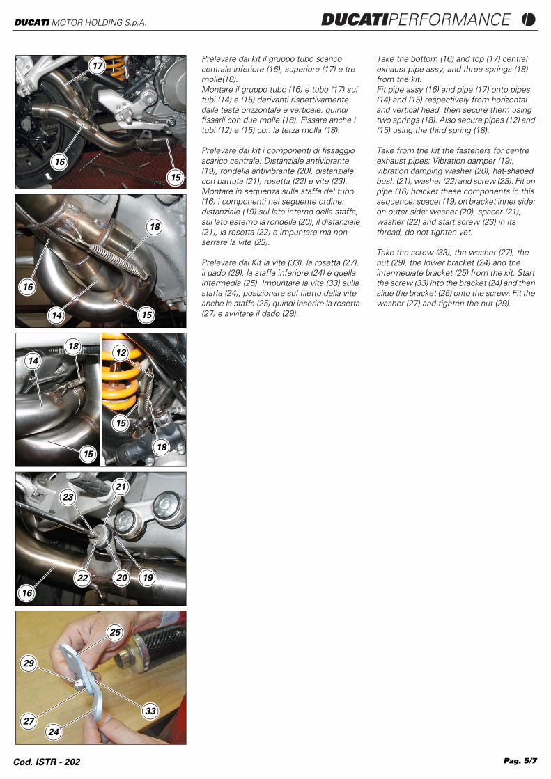
Take the bottom (16) and top (17) central exhaust pipe assy, and three springs (18) from the kit.Fit pipe assy (16) and pipe (17) onto pipes (14) and (15) respectively from horizontal and vertical head, then secure them using two springs (18). Also secure pipes (12) and (15) using the third spring (18).
Take from the kit the fasteners for centre exhaust pipes: Vibration damper (19), vibration damping washer (20), hat-shaped bush (21), washer (22) and screw (23). Fit on pipe (16) bracket these components in this sequence: spacer (19) on bracket inner side; on outer side: washer (20), spacer (21), washer (22) and start screw (23) in its thread, do not tighten yet.
Take the screw (33), the washer (27), the nut (29), the lower bracket (24) and the intermediate bracket (25) from the kit. Start the screw (33) into the bracket (24) and then slide the bracket (25) onto the screw. Fit the washer (27) and tighten the nut (29).
17
16
15
16
14 15
18
1412
15
18
15
18
2123
22 1920
16
29
33
25
27
24
Prelevare dal kit il gruppo tubo scarico centrale inferiore (16), superiore (17) e tre molle(18).Montare il gruppo tubo (16) e tubo (17) sui tubi (14) e (15) derivanti rispettivamente dalla testa orizzontale e verticale, quindi fissarli con due molle (18). Fissare anche i tubi (12) e (15) con la terza molla (18).
Prelevare dal kit i componenti di fissaggio scarico centrale: Distanziale antivibrante (19), rondella antivibrante (20), distanziale con battuta (21), rosetta (22) e vite (23). Montare in sequenza sulla staffa del tubo (16) i componenti nel seguente ordine: distanziale (19) sul lato interno della staffa, sul lato esterno la rondella (20), il distanziale (21), la rosetta (22) e impuntare ma non serrare la vite (23).
Prelevare dal Kit la vite (33), la rosetta (27), il dado (29), la staffa inferiore (24) e quella intermedia (25). Impuntare la vite (33) sulla staffa (24), posizionare sul filetto della vite anche la staffa (25) quindi inserire la rosetta (27) e avvitare il dado (29).
Pag. 5/7
Pag. 6/7
DUCATIPERFORMANCE DUCATI MOTOR HOLDING S.p.A.
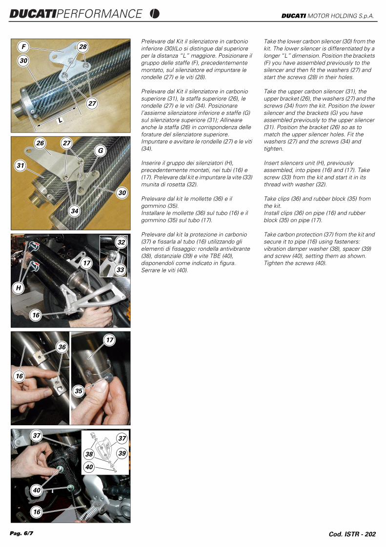
Take the lower carbon silencer (30) from the kit. The lower silencer is differentiated by a longer “L” dimension. Position the brackets (F) you have assembled previously to the silencer and then fit the washers (27) and start the screws (28) in their holes.
Take the upper carbon silencer (31), the upper bracket (26), the washers (27) and the screws (34) from the kit. Position the lower silencer and the brackets (G) you have assembled previously to the upper silencer (31). Position the bracket (26) so as to match the upper silencer holes. Fit the washers (27) and the screws (34) and tighten.
Insert silencers unit (H), previously assembled, into pipes (16) and (17). Take screw (33) from the kit and start it in its thread with washer (32).
Take clips (36) and rubber block (35) from the kit.Install clips (36) on pipe (16) and rubber block (35) on pipe (17).
Take carbon protection (37) from the kit and secure it to pipe (16) using fasteners: vibration damper washer (38), spacer (39) and screw (40), setting them as shown.Tighten the screws (40).
F
30
28
27
L
31
26
30
27
G
34
17
16
H
32
33
16
3617
35
40
16
37
38
37
39
40
Prelevare dal Kit il silenziatore in carbonio inferiore (30)(Lo si distingue dal superiore per la distanza “L” maggiore. Posizionare il gruppo delle staffe (F), precedentemente montato, sul silenziatore ed impuntare le rondelle (27) e le viti (28).
Prelevare dal Kit il silenziatore in carbonio superiore (31), la staffa superiore (26), le rondelle (27) e le viti (34). Posizionare l’assieme silenziatore inferiore e staffe (G) sul silenziatore superiore (31); Allineare anche la staffa (26) in corrispondenza delle forature del silenziatore superiore. Impuntare e avvitare le rondelle (27) e le viti (34).
Inserire il gruppo dei silenziatori (H), precedentemente montati, nei tubi (16) e (17). Prelevare dal kit e impuntare la vite (33) munita di rosetta (32).
Prelevare dal kit le mollette (36) e il gommino (35).Installare le mollette (36) sul tubo (16) e il gommino (35) sul tubo (17).
Prelevare dal kit la protezione in carbonio (37) e fissarla al tubo (16) utilizzando gli elementi di fissaggio: rondella antivibrante (38), distanziale (39) e vite TBE (40), disponendoli come indicato in figura. Serrare le viti (40).
Cod. ISTR - 202
Pag. 7/7
DUCATIPERFORMANCE DUCATI MOTOR HOLDING S.p.A.
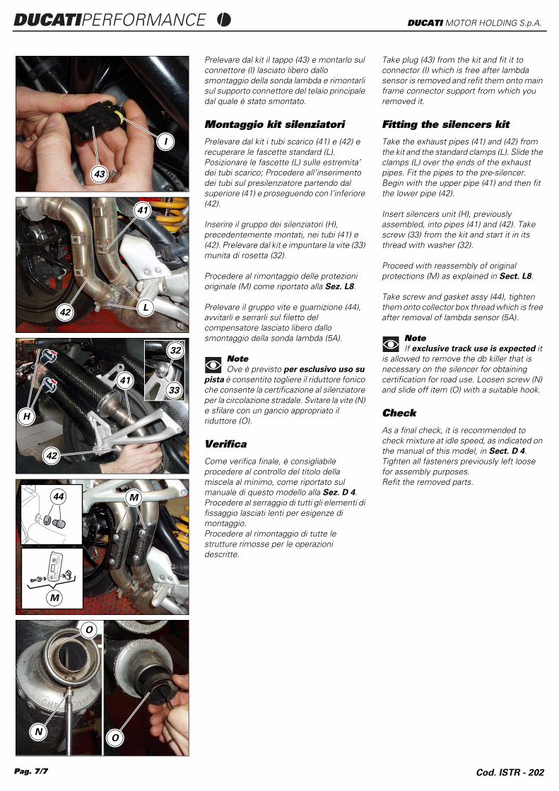
Take plug (43) from the kit and fit it to connector (I) which is free after lambda sensor is removed and refit them onto main frame connector support from which you removed it.
Fitting the silencers kit
Take the exhaust pipes (41) and (42) from the kit and the standard clamps (L). Slide the clamps (L) over the ends of the exhaust pipes. Fit the pipes to the pre-silencer. Begin with the upper pipe (41) and then fit the lower pipe (42).
Insert silencers unit (H), previously assembled, into pipes (41) and (42). Take screw (33) from the kit and start it in its thread with washer (32).
Proceed with reassembly of original protections (M) as explained in Sect. L8.
Take screw and gasket assy (44), tighten them onto collector box thread which is free after removal of lambda sensor (5A).
NoteIf exclusive track use is expected it
is allowed to remove the db killer that is necessary on the silencer for obtaining certification for road use. Loosen screw (N) and slide off item (O) with a suitable hook.
Check
As a final check, it is recommended to check mixture at idle speed, as indicated on the manual of this model, in Sect. D 4.Tighten all fasteners previously left loose for assembly purposes.Refit the removed parts.
I
43
41
42L
41
42
H
32
33
M
M44
O
ON
Prelevare dal kit il tappo (43) e montarlo sul connettore (I) lasciato libero dallo smontaggio della sonda lambda e rimontarli sul supporto connettore del telaio principale dal quale è stato smontato.
Montaggio kit silenziatori
Prelevare dal kit i tubi scarico (41) e (42) e recuperare le fascette standard (L). Posizionare le fascette (L) sulle estremita’ dei tubi scarico; Procedere all’inserimento dei tubi sul presilenziatore partendo dal superiore (41) e proseguendo con l’inferiore (42).
Inserire il gruppo dei silenziatori (H), precedentemente montati, nei tubi (41) e (42). Prelevare dal kit e impuntare la vite (33) munita di rosetta (32).
Procedere al rimontaggio delle protezioni originale (M) come riportato alla Sez. L8.
Prelevare il gruppo vite e guarnizione (44), avvitarli e serrarli sul filetto del compensatore lasciato libero dallo smontaggio della sonda lambda (5A).
NoteOve è previsto per esclusivo uso su
pista è consentito togliere il riduttore fonico che consente la certificazione al silenziatore per la circolazione stradale. Svitare la vite (N) e sfilare con un gancio appropriato il riduttore (O).
Verifica
Come verifica finale, è consigliabile procedere al controllo del titolo della miscela al minimo, come riportato sul manuale di questo modello alla Sez. D 4.Procedere al serraggio di tutti gli elementi di fissaggio lasciati lenti per esigenze di montaggio.Procedere al rimontaggio di tutte le strutture rimosse per le operazioni descritte.
Cod. ISTR - 202