MOD:YPR8522CC - confort-electrique.fr · 3 Accertarsi, prima di eseguire il collegamento elettrico,...
36
1 MOD:YPR8522CC ZVL370.02 ZVL370.02 / 03-11-2010 PROGRAMMATORE ELETTRONICO PER IL COMANDO DI PORTE E PORTONI MOTORIZZATI IN CORRENTE CONTINUA ELECTRONIC PROGRAMMER CONTROLLING DIRECT CURRENT POWERED MOTORISED GATES AND DOORS PROGRAMMATEUR ÉLECTRONIQUE POUR LA COMMANDE DE PORTES ET PORTAILS MOTORISÉS À COURANT CONTINU ELEKTRONISCHER PROGRAMMIERER FÜR DIE STEUERUNG VON MOTORISIERTEN TÜREN UND TOREN MIT GLEICHSTROM MOTOR PROGRAMADOR ELECTRONICO PARA EL CONTROL DE PUERTAS Y CANCELAS MOTORIZADAS EN CORRIENTE CONTINUA ATTENTION! Before installing this device read the following instructions carefully! IMPORTANT REMARKS Page 8 ELECTRONIC PROGRAMMER Page 8 ELECTRICAL CONNECTION Page 9 INDICATIONS ON THE DISPLAY Page 9 PROGRAMMING PROCEDURE Page 10-11 FUNCTION MODES Page 12 MANUAL OPERATION MODE Page 12 REMOTE CONTROL Page 12-13 BATTERY CHARGER (OPTIONAL) Page 13 STANDARDS AND CERTIFICATES Page 35 TECHNICAL SPECIFICATIONS Page 36 ATTENTION! Avant de commencer la pose, lire atten- tivement les instructions! CONSIGNES IMPORTANTES Page 14 PROGRAMMATEUR ÉLECTRONIQUE Page 14 BRANCHEMENT ÉLECTRIQUE Page 15 INDICATIONS DE L'AFFICHEUR Page 15 PROCÉDÉ DE PROGRAMMATION Page 16-17 MODES DE FONCTIONNEMENT Page 18 MODE "MANUEL" Page 18 COMMANDE PAR RADIO Page 18-19 CHARGEUR DE BATTERIE (EN OPTION) Page 19 NORMES ET CERTIFICATS Page 35 CARACTÉRISTIQUES TECHNIQUES Page 36 ACHTUNG! Bevor mit der Installation begonnen wird, sollte die Anleitung aufmerksam gelesen werden. WICHTIGE HINWEISE Seite 20 ELEKTRONISCHER STEUERUNGSEINHEIT Seite 20 ELEKTROANSCHLUSS Seite 21 ANZEIGEN AUF DEM DISPLAY Seite 21 PROGRAMMIERUNG Seite 22-23 FUNKTIONSARTEN Seite 24 MODALITÄT "MANUELLER BETRIEB" Seite 24 FUNKSTEUERUNG Seite 24-25 BATTERIELADEGERÄT (EXTRA) Seite 25 BESTIMMUNGEN UND ZERTIFIKATE Seite 35 TECHNISCHE DATEN Seite 36 ¡ATENCIÓN! Antes de iniciar la instalación del sistema, leer atentamente las instrucciones. ADVERTENCIAS IMPORTANTES Página 26 PROGRAMADOR ELECTRÓNICO Página 26 CONEXIÓN ELÉCTRICA Página 27 INDICACIONES EN EL DISPLAY Página 27 PROCEDIMIENTO PARA LA PROGRAMACIÓN Página 28-29 MODALIDAD DE FUNCIONAMIENTO Página 30 MODALIDAD MANUAL Página 30 MANDO VÍA RADIO Página 30-31 CARGADOR DE BATERÍAS (OPCIONAL) Página 31 NORMAS Y CERTIFICADOS Página 35 ESPECIFICACIONES TÉCNICAS Página 36 ATTENZIONE! Prima di iniziare l'installazione leggere le istruzioni attentamente! AVVERTENZE Pagina 2 PROGRAMMATORE ELETTRONICO Pagina 2 COLLEGAMENTO ELETTRICO Pagina 3 INDICAZIONI DEL DISPLAY Pagina 3 PROCEDURA DI PROGRAMMAZIONE Pagina 4-5 MODALITÀ DI FUNZIONAMENTO Pagina 6 MODALITÀ UOMO PRESENTE Pagina 6 COMANDO VIA RADIO Pagina 6-7 CARICA BATTERIE (OPZIONALE) Pagina 7 NORME E CERTIFICAZIONI Pagina 35 CARATTERISTICHE TECNICHE Pagina 36 FRANÇAIS ENGLISH DEUTSCH ITALIANO ESPAÑOL
Transcript of MOD:YPR8522CC - confort-electrique.fr · 3 Accertarsi, prima di eseguire il collegamento elettrico,...

1
MOD:YPR8522CCZVL370.02
ZV
L370
.02
/ 03
-11-
2010
PROGRAMMATORE ELETTRONICO PER IL COMANDO DI PORTE E PORTONI MOTORIZZATI IN CORRENTE CONTINUA ELECTRONIC PROGRAMMER CONTROLLING DIRECT CURRENT POWERED MOTORISED GATES AND DOORS PROGRAMMATEUR ÉLECTRONIQUE POUR LA COMMANDE DE PORTES ET PORTAILS MOTORISÉS À COURANT CONTINUELEKTRONISCHER PROGRAMMIERER FÜR DIE STEUERUNG VON MOTORISIERTEN TÜREN UND TOREN MIT GLEICHSTROM MOTORPROGRAMADOR ELECTRONICO PARA EL CONTROL DE PUERTAS Y CANCELAS MOTORIZADAS EN CORRIENTE CONTINUA
ATTENTION! Before installing this device read the following instructions carefully!
IMPORTANT REMARKS Page 8ELECTRONIC PROGRAMMER Page 8ELECTRICAL CONNECTION Page 9INDICATIONS ON THE DISPLAY Page 9PROGRAMMING PROCEDURE Page 10-11FUNCTION MODES Page 12MANUAL OPERATION MODE Page 12REMOTE CONTROL Page 12-13BATTERY CHARGER (OPTIONAL) Page 13STANDARDS AND CERTIFICATES Page 35TECHNICAL SPECIFICATIONS Page 36
ATTENTION! Avant de commencer la pose, lire atten-tivement les instructions!
CONSIGNES IMPORTANTES Page 14PROGRAMMATEUR ÉLECTRONIQUE Page 14BRANCHEMENT ÉLECTRIQUE Page 15INDICATIONS DE L'AFFICHEUR Page 15PROCÉDÉ DE PROGRAMMATION Page 16-17MODES DE FONCTIONNEMENT Page 18MODE "MANUEL" Page 18COMMANDE PAR RADIO Page 18-19CHARGEUR DE BATTERIE (EN OPTION) Page 19NORMES ET CERTIFICATS Page 35CARACTÉRISTIQUES TECHNIQUES Page 36
ACHTUNG! Bevor mit der Installation begonnen wird, sollte die Anleitung aufmerksam gelesen werden.
WICHTIGE HINWEISE Seite 20ELEKTRONISCHER STEUERUNGSEINHEIT Seite 20ELEKTROANSCHLUSS Seite 21ANZEIGEN AUF DEM DISPLAY Seite 21PROGRAMMIERUNG Seite 22-23FUNKTIONSARTEN Seite 24MODALITÄT "MANUELLER BETRIEB" Seite 24FUNKSTEUERUNG Seite 24-25BATTERIELADEGERÄT (EXTRA) Seite 25BESTIMMUNGEN UND ZERTIFIKATE Seite 35TECHNISCHE DATEN Seite 36
¡ATENCIÓN! Antes de iniciar la instalación del sistema, leer atentamente las instrucciones.
ADVERTENCIAS IMPORTANTES Página 26PROGRAMADOR ELECTRÓNICO Página 26CONEXIÓN ELÉCTRICA Página 27INDICACIONES EN EL DISPLAY Página 27PROCEDIMIENTO PARA LA PROGRAMACIÓN Página 28-29MODALIDAD DE FUNCIONAMIENTO Página 30MODALIDAD MANUAL Página 30MANDO VÍA RADIO Página 30-31CARGADOR DE BATERÍAS (OPCIONAL) Página 31NORMAS Y CERTIFICADOS Página 35ESPECIFICACIONES TÉCNICAS Página 36
ATTENZIONE! Prima di iniziare l'installazione leggere le istruzioni attentamente!
AVVERTENZE Pagina 2PROGRAMMATORE ELETTRONICO Pagina 2COLLEGAMENTO ELETTRICO Pagina 3INDICAZIONI DEL DISPLAY Pagina 3PROCEDURA DI PROGRAMMAZIONE Pagina 4-5MODALITÀ DI FUNZIONAMENTO Pagina 6MODALITÀ UOMO PRESENTE Pagina 6COMANDO VIA RADIO Pagina 6-7CARICA BATTERIE (OPZIONALE) Pagina 7NORME E CERTIFICAZIONI Pagina 35CARATTERISTICHE TECNICHE Pagina 36
FRANÇAIS
ENGLISH
DEUTSCHITALIANO
ESPAÑOL

2
AVVERTENZE IMPORTANTI AVVERTENZE IMPORTANTI AVVERTENZE IMPORTANTI
La programmazione, eseguibile mediante due soli pulsanti, permette la configurazione del sistema, della durata della fase di rallentamento, dei sensori di sforzo e dei tempi di lavoro-pausa. L’intervento del sensore antischiacciamento/anticonvogliamento in fase di chiusura causa l’inver-sione del moto e lo stesso avviene nella fase di apertura (se la richiusura automatica è abilitata: in caso contrario causa solamente il blocco). Se il moto è nella fase terminale, invece, il sensore agisce come finecorsa.
Descrizione scheda elettronicaB1 Buzzer segnalazione modalità "via radio"DS1 Display a 7 segmentiF1 Fusibile 1A rapido - protezione contro sovraccarichi linea a 24V F2 Fusibile 3,15A ritardato - protezione contro sovraccarichi alimentazione
elettroserratura (solo nel funzionamento a batteria) F3 Fusibile 10A rapido - protezione contro sovraccarichi alimentazione
motori F4 Fusibile 10A rapido - protezione contro sovraccarichi alimentazione
motori J1 Selezione canali J2 Abilitazione alla memorizzazione via radio (senza aprire il contenitore)L1 LED di alimentazione schedaL2 LED di gestione codici TXL3 LED di modalità uomo presenteL4 LED di segnalazione finecorsa chiusura anta 1 (FCC1)L5 LED di segnalazione finecorsa apertura anta 1 (FCA1)L6 LED di segnalazione finecorsa chiusura anta 2 (FCC2)L7 LED di segnalazione finecorsa apertura anta 2 (FCA2)L8 LED di segnalazione TAL9 LED di segnalazione TCL10 LED di segnalazione TBL11 LED di segnalazione FTC_IL12 LED di segnalazione FTC_SM1 Modulo di memoria (300 codici)P1 Tasto di programmazioneP2 Tasto di selezioneP3 Tasto di memorizzazione codice TX P4 Tasto di cancellazione codice TXR1 Modulo RF a 433.92 MHz V0-V1 Connessione a secondario 1 del trasformatore (0-24 Vac) grigio-grigioVB Connessione a tensione di batteria 12 Vdc (solo per funzionamento
elettroserratura in modalità batteria)V2-V3 Connessione a secondario 2 del trasformatore (0-15 Vac) marrone-
marroneV4-V5 Connessione a secondario 3 del trasformatore (0-20 Vac) rosso-rosso
Attenzione! Solo per clienti dell’EU - Marcatura WEEE.Il simbolo indica che il prodotto alla fine della propria vita utile deve essere raccolto separatamente dagli altri rifiuti. L’utente dovrà pertanto conferire l’apparecchiatura agli idonei centri di raccolta differenziata dei rifiuti elettronici ed elettrici, oppure riconsegnarla al rivenditore al momento dell’acquisto di una nuova apparecchiatura di tipo equivalente, in ragione di uno a uno.
L’adeguata raccolta differenziata per l’avvio al riciclaggio, al trattamento e allo smaltimento ambientalmente compatibile contribuisce ad evitare possibili effetti negativi sull’ambiente e sulla salute e favorisce il riciclo dei materiali.Lo smaltimento abusivo del prodotto da parte del detentore comporta l’ap-plicazione delle sanzioni amministrative previste dalla normativa vigente nello Stato Comunitario di appartenenza.
•Prima di dar inizio all’installazione leggere attentamente il presente fascicolo. In particolare, prendere visione dei dispositivi di sicurezza previsti dal prodotto per utilizzarli con la massima efficacia.
•Nontuttiidispositividisicurezzaeventualmenteresiobbligatoridanormevigenti in Italia o all’estero sono presi in considerazione dal presente fasci-colo. L’installatore dovrà provvedersi personalmente, integrando i dispositivi mancanti ed installandoli a monte o a valle dei prodotti descritti nel presente fascicolo.
• L’utilizzodeiprodottielalorodestinazioneadusidiversidaquelliprevistie/oconsigliati, non è stata sperimentata dal costruttore, pertanto i lavori eseguiti sono sotto la completa responsabilità dell’installatore.
• Ilpresentemanualesirivolgeapersoneabilitateall'installazionedi"Appa-recchi utilizzatori di energia elettrica" e richiede una buona conoscenza della tecnica, esercitata in forma professionale. Il costruttore declina ogni responsabilità per eventuali danni provocati dalla mancata osservanza nell'installazione della norme di sicurezza attualmente in vigore.
Attenzione! Il programmatore è utilizzabile esclusivamente con i motori della Cardin Elettronica delle serie "BL" , "HL" e "GL".
Programmatore per motore in corrente continua con ricevente incorporata, che permette la memorizzazione di 300 codici utente (vedere "comando via radio", a pag. 6). La decodifica è di tipo 'rolling code', e la frequenza di funzionamento è di 433.92 MHz. La velocità di rotazione dei motori è controllata elettronicamente, con par-tenza lenta e successivo incremento; la velocità viene ridotta con anticipo rispetto all'arrivo a finecorsa, in modo da ottenere un arresto controllato (se il rallentamento non viene escluso nella procedura di programmazione).
LEGGERE ATTENTAMENTE LE SEGUENTI AVVERTENZE PRIMA DI PROCEDERE ALL’INSTALLAZIONE. PRESTARE PARTICO-LARE ATTENZIONE A TUTTE LE SEGNALAZIONI DISPOSTE NEL TESTO. IL MANCATO RISPETTO DI QUESTE POTREBBE COMPROMETTERE IL BUON FUNZIONAMENTO DEL SISTEMA E CREARE SITUAZIONI DI PERICOLO GRAVE PER L'OPERA-TORE E GLI UTILIZZATORI DEL SISTEMA STESSO. CONSERVARE QUESTE ISTRUZIONI PER OGNI FUTURO RIFERIMENTO.
PROGRAMMATORE ELETTRONICO
Co
llegam
enti scheda b
ase
PR
G852
19-12-2008
DC
0445D
escription :
Prod
uct Cod
e :
Date:
Draw
ing numb
er :
P.J.Heath
CA
RD
IN E
LE
TT
RO
NIC
A S
.p.A
- 31020 San Vend
emiano
(TV
) Italy - via Raffaello
, 36 Tel: 0438/401818 Fax: 0438/401831
Draft :
All rights reserved
. Unauthorised
copying or use of the inform
ation contained in this d
ocument is p
unishable b
y law
PR
G852
F2 T3.15A
CS1046B DC0344
F1 F1A
2930
P4P3
DELMEMO
L2
DS1
V5
V4
V3
V2
ELS
12V
1098765 161514131211 222120191817 282726252423
LC- O
UT C
H2
LS 24V
CM
N
LP 24V
OU
T 24V
CM
N
FCC
1
FCA
1
FCC
2
FCA
2
TAL
TA TC TD CM
N
CM
N
TB FTC_I
FTC_S
CM
N
F4 F10A
F3 F10A
P2P1
SELPROG L3
L4 L5 L6 L7 L8 L9 L10 L11 L12
L1
VB
V1V0
CHA
CHB
CHC
CHD
CH 1Comando dinamicoDynamic command
Commande dynamiqueDynamische Steuerung
Mando dinámico
Selezione canaliChannel selectionSélection canalKanalwahlSelección
CH 2Comando ausiliarioAuxiliary command
Commande auxiliareHilfssteuerungMando auxiliar
CHA
CHBCHC
CHD
J1
CH
A
CH
B
CH
C
CH
D
M1 M2
2 31 4
R1M1
S449
24C16A)
J2 J2
B1
SPR
1

3
Accertarsi, prima di eseguire il collegamento elettrico, che la tensione e la frequenza riportate sulla targhetta caratteristiche corrispondano a quelle dell'impianto di alimentazione. Tra la centralina di comando e la rete deve essere interposto un interruttore onnipolare, con distanza di apertura tra i contatti di almeno 3 mm.
• Collegareifilidicomandoequelliprovenientidallesicurezze.• Collegareilcavodialimentazionealdispositivo,mediantelamorsettieravolante
(che è già collegata al primario del trasformatore, fili bianco nero).• Nonutilizzarecavoconconduttoriinalluminio;nonstagnarel’estremitàdeicavi
da inserire in morsettiera; utilizzare cavo con marcatura T min 85°C resistente agli agenti atmosferici.
• Iconduttoridovrannoessereadeguatamentefissatiinprossimitàdellamorsettierain modo che tale fissaggio serri sia l’isolamento che il conduttore (è sufficiente una fascetta).
Collegamenti morsettiera 1-2 Uscita per motore 1: in apertura: positivo su morsetto 1 e negativo su morsetto 2 in chiusura: negativo su morsetto 1 e positivo su morsetto 23-4 Uscita per motore 2: in apertura: positivo su morsetto 3 e negativo su morsetto 4 in chiusura: negativo su morsetto 3 e positivo su morsetto 45 Comuni per tutti gli ingressi e uscite6 Uscita per elettroserratura (pilotata in continua) 12 Vdc -15 W; deve essere
del tipo basculante (non a riarmo automatico) in quanto l'attivazione dura 1 s.7-8 Uscita (contatto puro, N.A.) per attivazione luce di cortesia (alimentata a parte,
Vmax= 30 Vac/dc: Imax=1A) oppure per secondo canale radio. La selezione viene fatta in programmazione
9 Uscita lampada spia 24 Vac 3 W 10 Uscita lampeggiante 24 Vac 10 W (attivazione continua o intermittente)11 Uscita per alimentazione carichi esterni 24 Vac 10 W 12-13 Comuni per tutti gli ingressi e uscite14 FCC1 (contatto N.C.) ingresso finecorsa di chiusura anta 115 FCA1 (contatto N.C.) ingresso finecorsa di apertura anta 116 FCC2 (contatto N.C.) ingresso finecorsa di chiusura anta 217 FCA2 (contatto N.C.) ingresso finecorsa di apertura anta 218 TAL (contatto N.A.) ingresso pulsante di apertura limitata 19 TA (contatto N.A.) ingresso pulsante di apertura20 TC (contatto N.A.) ingresso pulsante di chiusura21 TD Ingresso (contatto N.A.) per comando sequenziale (apre-blocco-chiude-
blocco oppure apre-chiude con inversione solo in chiusura, a seconda delle impostazioni del programma)
22-23 Comuni per tutti gli ingressi e uscite24 TB (contatto N.C.) ingresso pulsante di blocco25 FTC_I (contatto N.C.) ingresso per dispositivi di sicurezza (fotocellula di
inversione in chiusura). L'apertura del contatto, conseguente all'intervento dei dispositivi di sicurezza, durante la fase di chiusura, attuerà l'inversione di moto.
26 FTC_S (contatto N.C.) ingresso per dispositivi di sicurezza (fotocellula di stop). Al ritorno nella condizione di riposo, dopo il tempo di pausa il moto riprenderà in chiusura (solo se in modalità automatica).
27-28 Comuni per tutti gli ingressi e uscite29 Centrale antenna ricevitore radio; collegare un filo rigido di 17cm oppure
un'antenna esterna ANS400 mediante cavo coassiale (RG58 imp. 50Ω)30 Massa antenna ricevitore radio
N.B. TUTTI I CONTATTI N.C. NON UTILIZZATI VANNO PONTICELLATI(non è necessario per i finecorsa disabilitati in programmazione)
Alimentare il circuito e verificare che lo stato dei LED rossi di segnalazione sia come segue:
- L1 LED di alimentazione circuito acceso- L4 LED di finecorsa di chiusura anta 1 "FCC1" acceso*- L5 LED di finecorsa di apertura anta 1 "FCA1" acceso*- L6 LED di finecorsa di chiusura anta 2 "FCC2" acceso*- L7 LED di finecorsa di apertura anta 2 "FCA2" acceso*- L8 LED di segnalazione tasto apertura "TA" spento- L9 LED di segnalazione tasto chiusura "TC" spento- L10 LED di sicurezza tasto blocco "TB" acceso*- L11 LED di sicurezza fotocellule d'inversione "FTC_I" acceso*- L12 LED di sicurezza fotocellule di stop "FTC_S" acceso*
* I LED sono accesi se la relativa sicurezza non è attivata (dipende dalla posizione dell'anta e dalla presenza o meno dei finecorsa). Verificare che l'attivazione delle sicurezze porti allo spegnimento del LED ad esse associato.Nel caso in cui il LED di alimentazione L1 non si accenda verificare lo stato del fusibile "F1" ed il collegamento del cavo di alimentazione a 230V ac.Nel caso in cui uno o più LED di sicurezza non si accendano verificare i contatti del relativo dispositivo di sicurezza collegato oppure controllare che i contatti delle sicurezze non utilizzate siano ponticellati sulla morsettiera.
allarme per entrambi i finecorsa meccanici attivati contemporaneamente
errore sui parametri in memoria
blocco in modalità di programmazione tempi (a causa di: TB, FTC_I, FTC_S)
definizione della configurazione del sistema
fase di attesa dopo la programmazione dei parametri
fase di attesa dopo la programmazione del rallentamento
fase di attesa dopo la programmazione livello dei sensori di corrente
tempo di rallentamento (valore 1)
livello 1 per il sensore di corrente
programmazione dei tempi di lavoro
fase di apertura
blocco
pausa per la richiusura automatica (solo se abilitata)
fase di chiusura
aggiornamento del sensore di corrente anta 1 (in programmazione)
aggiornamento del sensore di corrente anta 2 (in programmazione)
aggiornamento di entrambi i sensori di corrente "anta 1 - 2" (in programmazione)
Apertura + compensazione sensore 1
Apertura + compensazione sensore 2
Chiusura + compensazione sensore 1
Chiusura + compensazione sensore 2
Modalità batteria con batteria carica
Modalità batteria con batteria scarica
Blocco per batteria scarica
COLLEGAMENTO ELETTRONICO INDICAZIONI DEL DISPLAY

4
Prima di iniziare accertarsi che le ante siano chiuse: il display a LED è spento e i LED L10, L11, L12 siano tutti accesi.
I LED L4 e L6 (se sono installati i finecorsa di chiusura anta 1 e 2) sono spenti (finecorsa di chiusura attivati).
PROCEDURA DI PROGRAMMAZIONE (Impostazioni del programmatore, del sensore di corrente e dei tempi di lavoro)
PREMERE SEL
PREMERE PROG
Singolomotore
Configurazionea battente
Configurazionea scorrevole
FUNZIONEATTIVA
Morsetti 7,8:luce di cortesia
Morsetti 7,8:uscita CH2 radio
TD: apre-chiude
TD: apre-blocco
chiude-blocco
Prelampeggioinserito
Prelampeggioescluso
Finecorsamotore 1abilitati
Finecorsamotore 1disabilitati
DS1PREMERE IL TASTO PROG PER PIÙ DI 4 SECONDI: COMPARE LA LETTERA "d" CHE INDICA LA DEFINIZIONE DEI PARAMETRI DI SISTEMA (FASE "A")
FUNZIONEATTIVA
PREMERE SEL
1...20 s
ATTENDERE CIRCA 20 SECONDI SENZA PREMERE NESSUN TASTO: IL PRG SALVA I PARAMETRI FIN QUI IMPOSTATI ED ESCE DALLA PROGRAMMAZIONE.
DOPO 1 SECONDO COMPARE LA CIFRA "1" ( PRIMO PASSO DI PROGRAMMAZIONE) CHE PUÒ ESSERE INTERMITTENTE O FISSA
Nota 1
Elettroserraturaabilitata
Elettroserraturadisabilitata
Richiusuraautomatica
abilitata
Richiusuraautomatica
esclusa
LA PRESSIONE DEL TASTO "PROG" PORTA ALLA FASE "C". PROGRAMMAZIONE DEL SENSORE DI CORRENTE. I VALORI SELEZIONABILI VANNO DA 1 A 3.
Doppiomotore
PREMERE SEL
Finecorsamotore 2abilitati
Finecorsamotore 2disabilitati
Lampeggiantecon elettronica
a bordo
Lampeggianteattivato da PRG
Rallentamentoabilitato
Rallentamentoescluso
Lampada spianon
intermittente
Lampada spiaintermittente
Fotocellule FTC_I
attive anchein blocco
Fotocellule FTC_I
attive solo inchiusura
PREMERE PROG
Nota 2
Nota 3
Nota 1 L'inversione del moto si ha solamente in fase di chiusura. Nota 2 La lampada spia lampeggia lentamente durante l'apertura, velocemente
durante la chiusura; resta accesa quando il cancello non è completamente chiuso, ed è spenta quando il cancello è completamente chiuso.
Nota 3 Se le fotocellule risultano in allarme, ed il cancello è in stato di blocco, non viene accettato nessun comando di moto (nemmeno di apertura).
PREMERE PROG
PREMERE SEL
PREMERE PROG
PREMERE SEL
PREMERE PROG
PREMERE SEL
PREMERE PROG
PREMERE SEL
PREMERE PROG
PREMERE SEL
PREMERE PROG
PREMERE SEL
PREMERE PROG
PREMERE SEL
PREMERE PROG
PREMERE SEL
PREMERE PROG
PREMERE SEL
PREMERE PROG
PREMERE SEL
PREMERE PROG
PREMERE SEL
PREMERE PROG
PREMERE SEL
ALTERNATI
PREMERE PROG
PREMERE PROG
ALTERNATI
PREMERE PROG
VALORE FISSO
PREMERE SEL
ALTERNATIVALORE
FISSO
PREMERE SEL
VALORE FISSO
selezione3 secondi
selezione4,5 secondi
selezione6 secondi
PREMERE PROG
PREMERE SEL
ATTENDERE CIRCA 20 SECONDI SENZA PREMERE NESSUN TASTO: IL PRG SALVA I PARAMETRI FIN QUI IMPOSTATI ED ESCE DALLA PROGRAMMAZIONE.
Attenzione! La selezione di R1, R2 e R3 deve essere fatta anche se il rallentamento è stato escluso: bisogna infatti stabilire il tempo durante il quale il sensore di corrente agisce come finecorsa in prossimità dell'arrivo in battuta. Si consiglia di selezionare un tempo di 4,5 secondi.La selezione dovrà permettere un arresto dolce del moto, limitando all’essenziale il percorso alla velocità ridotta.
1...20 s
PREMERE SEL
ALTERNATI
PREMERE PROG
PREMERE PROG
ALTERNATI
PREMERE PROG
VALORE FISSO
PREMERE SEL
ALTERNATIVALORE
FISSO
PREMERE SEL
VALORE FISSO
coppiaminima
coppiamedia
coppiamassima
PREMERE PROG
PREMERE SEL
ATTENDERE CIRCA 20 SECONDI SENZA PREMERE NESSUN TASTO: IL PRG SALVA I PARAMETRI FIN QUI IMPOSTATI ED ESCE DALLA PROGRAMMAZIONE.
Attenzione! Il programmatore esegue il controllo dell'assorbimento del motore, rilevando l'aumento dello sforzo oltre i limiti consentiti nel normale funzionamento. Per garantire un corretto funzionamento anche al variare delle condizioni climatiche e meccaniche, il programmatore procede ad un’autotaratura che permette al sistema di rilevare eventuali maggiori resistenze al moto che non erano presenti all’atto della programmazione, e di compensarle in modo che lo sforzo per arrestare l’anta non ne sia ridotto, garantendo il funzionamento ottimale (vedere "Compensazione dei sensori di corrente", pagina 6).
LA PRESSIONE DEL TASTO "PROG" PORTA ALLA FASE "B". PROGRAMMAZIONE DEL TEMPO DI RALLENTAMENTO. I VALORI SELEZIONABILI VANNO DA 1 A 3.
LA PRESSIONE DEL TASTO "PROG" PORTA ALL’ULTIMA FASE "D". LA PROGRAMMAZIONE DEI TEMPI DI LAVORO.
CONTINUARE A PAGINA 5

5
Premere prog per iniziare la programmazione con:
Nella fase “A” passo “1” è stato selezionato il parametro singolo motore
SI
Apre anta 1
Fine tempo di pausa (inizio chiusura )
SI NO
Premere prog prima che l’anta arrivi in battuta. Fine taratura sensore 1 (in apertura)
Quando l’anta arriva in battuta o attiva il finecorsa di apertura inizio il conteggio del tempo di pausa
Chiude anta 1
PREMERE PROG
Apre anta 1 e 2
Chiude anta 1 e 2
PREMERE PROG
La fine della programmazione viene segnalata dall’accensione della luce di cortesia e si spegne il display
PREMERE PROG
Apre anta 1 e dopo 2 secondi di sfasamento apre anta 2
PREMERE PROG
Premere prog prima che l’anta 2 arrivi in battuta. Fine taratura sensore 2 (in apertura)
Quando entrambe le ante sono arrivate in battuta o quando sono stati attivati entrambi i finecorsa di apertura inizia il conteggiodel tempo di pausa
PREMERE PROG
PREMERE PROG
La fine della programmazione viene segnalata dall’accensione della luce di cortesia e si spegne il display
PREMERE PROG
DS1
Nella fase “A” passo “2” è stato selezionato il parametro configurazione scorrevoli
PREMERE PROG
PREMERE PROG
PREMERE PROG
Premere prog prima che l’anta arrivi in battuta. Fine taratura sensore 1 (in chiusura)
PREMERE PROG
La fine della programmazione viene segnalata dall’accensione della luce di cortesia e si spegne il display
PREMERE PROG
PREMERE PROG
PREMERE PROG
DS1
PREMERE PROG
Premere prog prima che l’anta 1 arrivi in battuta. Fine taratura sensore 1 (in apertura)
Premere prog prima che l’anta 2 arrivi in battuta. Fine taratura sensore 2 (in apertura)
Fine tempo di pausa (inizio chiusura )
Premere prog prima che l’anta 2 arrivi in battuta. Fine taratura sensore 2 (in chiusura)
Premere prog prima che l’anta 1 arrivi in battuta. Fine taratura sensore 1 (in chiusura)
PREMERE PROG
Premere prog prima che l’anta 1 arrivi in battuta. Fine taratura sensore 1 (in apertura)
Fine tempo di pausa inizio chiusura anta 2
Chiude anta 2
PREMERE PROG
Chiude anta 1Fine sfasamento chiusura - Nota 2 -
Premere prog prima che l’anta 1 arrivi in battuta. Fine taratura sensore 1 (in chiusura)
Premere prog prima che l’anta 2 arrivi in battuta. Fine taratura sensore 2 (in chiusura)
DS1
Nota 1: Selezionando l’anta singola si disabilitano i finecorsa per anta 2. L’esclusione, in fase di programmazione, dei finecorsa evita di doverli ponticellare sulla morsettiera.
NO
- Singola Anta -
Premere prog per iniziare la programmazione con:
- Due Ante Scorrevoli -
Quando entrambe le ante sono arrivate in battuta o quando sono stati attivati entrambi i finecorsa di apertura inizia il conteggiodel tempo di pausa
Premere prog per iniziare la programmazione con:
- Due Ante Battenti-
CONTINUA DA PAGINA 4 FASE "D" PROGRAMMAZIONE DEI TEMPI DI LAVORO
La programmazione viene eseguita passo passo dal sistema attivando i motori in modo congruente alle impostazioni fatte ai passi precedenti (es.: avendo sele-zionato la configurazione ad un'anta, sarà attivato solo il motore N°1). Se l’elettroserratura e il prelampeggio sono stati abilitati, questi vengono attivati anche in fase di programmazione.
Nota 2: Il massimo ritardo in chiusura per anta 1 è pari al tempo di lavoro di anta 2. •Unavolta iniziata laprogrammazionetempi,per terminarla (senza però memorizzare i tempi fino a quel momento trascorsi: si tratta dunque di un’uscita anomala dalla modalità di program-mazione) è sufficiente premere il tasto SEL; le ante si bloccano, e vengono salvati in memoria solamente i parametri per la definizione del sistema, compresa la selezione del tempo di rallentamento e del livello di coppia.
•L'interventodellefotocellulediinversione/bloccoolapressionedeltastodibloccoportaall'arrestodel moto delle ante, mentre il lampeggiante rimane comunque attivato, segnalando che il program-matore è in una fase attiva, e sul display si ha l'indicazione "b" lampeggiante. Il conteggio del tempo di lavoro è bloccato, ma al cessare della situazione di allarme, o al rilascio del tasto di blocco (attivo solamente finché è premuto) il moto delle ante riprende automaticamente, come pure l'aggiornamento del tempo di lavoro. •L'interventodelfinecorsameccanicooppuredelfinecorsaamperometrico (sensoredicorrente)causa l'arrestodelmotodelleantee lafinedel tempodilavoro. Attenzione! Programmare i tempi di lavoro in modo da avere sempre la completa apertura delle ante; in caso contrario non è garantibile il completamento della manovra (vedere considerazioni al paragrafo "Finecorsa a tempo").

6
1) AutomaticaSi seleziona abilitando la richiusura automatica (passo "6" di programmazione, numero "6" fisso). Partendo dalla condizione di completamente chiuso, il comando di apertura inizia un ciclo completo di funzionamento, che terminerà con la richiusura automatica e lo spegnimento temporizzato della luce di cortesia. La richiusura automatica entra in funzione con un ritardo pari al tempo di pausa programmato, a partire dal termine della manovra di apertura oppure dall'istante in cui sono intervenute le fotocellule per l'ultima volta durante il tempo di pausa (l'intervento delle fotocellule causa un reset del tempo di pausa). Durante il tempo di pausa, sul display lampeggia il simbolo . La pressione del tasto di blocco durante il tempo di pausa impedisce la richiusura automatica con conseguente blocco del lampeggio sul display.L'intervento dei finecorsa meccanici o dei finecorsa amperometrici porta al blocco dell'anta.La lampada spia rimane accesa quando il portone non è completamente chiuso.
Nota: la luce di cortesia si accende ad ogni comando di movimento impartito al sistema, sia via filo che via radio; l'intervento delle fotocellule durante l'operazione di chiusura non ha effetto sulla temporizzazione della luce di cortesia.
2) Semi-automaticaSi seleziona disabilitando la richiusura automatica (passo "6" di programmazione, numero "6" lampeggiante).Il ciclo di lavoro è gestito con comandi separati di apertura e chiusura. Arrivato in posizione di completa apertura il sistema attende un comando di chiusura via radio o tramite tasto per completare il ciclo. L'intervento del finecorsa di apertura causa il blocco dell'anta, e la fine della manovra di apertura. A partire dal termine della manovra di apertura, la luce di cortesia si spegne alla fine del tempo prestabilito.La lampada spia rimane accesa quando il portone non è completamente chiuso.
APERTURA LIMITATAViene eseguita su anta 1; se si è configurato il sistema come doppia anta, si avrà l’apertura completa di anta 1; se si è configurato il sistema come singola anta, si avrà l’apertura parziale di anta 1 (circa 1/3 della corsa). È possibile eseguire il comando solo con le ante completamente chiuse; se durante l'apertura limitata si attiva nuovamente il comando "TAL", anta 1 si bloccherà, e ad un successivo comando andrà in chiusura. A questo punto il comando non sarà più eseguito fino alla completa chiusura.
LUCE DI CORTESIA / USCITA CH2 RADIOI morsetti "7","8" fanno capo ai contatti C-NA di un relay; esso potrà essere attivato con la solita modalità di "luce di cortesia" (contatto chiuso) per un tempo pari a quello programmato oppure direttamente dal secondo canale radio, selezionabile sulla decodifica integrata nella centralina (jumper "J1"). I morsetti "7","8" forniscono solamente un contatto puro, e non danno una tensione all’esterno; questo significa che per usare la luce di cortesia sarà necessario alimentare il circuito a parte, ed usare il contatto come semplice interruttore.
Attenzione! Sulla scheda del programmatore non è presente la tensione a 230V ac: si ha solamente la bassa tensione. Per la conformità alla normativa sulla sicurezza elettrica, che prescrive determinati isolamenti tra le piste ad alta tensione (230V ac) e bassa tensione (24V ac) non sarà possibile collegare i morsetti 7 e 8 direttamente ad un circuito dove sia applicata una tensione a 230V ac. La massima tensione consentita è di 30V ac/dc.
MODALITÀ "UOMO PRESENTE"Può essere utilizzata per muovere le ante in chiusura (o in apertura) sotto il diretto controllo dell’operatore; in questa modalità le sicurezze FTC_I, FTC_S e TB agiscono soltanto finché sono in allarme. Lo scopo è quello di facilitare la manovra di installazione, e di avere le ante completamente chiuse prima di procedere alla programmazione del sistema. In questa modalità il LED "L3" (contrassegnato con "UPL") rimane acceso. La modalità "uomo pre-sente" può essere azionata anche in funzionamento a batteria; i motori vengono alimentati con la tensione massima (velocità di regime) indipendentemente dall’abilitazione o meno del rallentamento. Le sicurezze FTC_I (solo in chiusura, indipendentemente dalla selezione al passo "C" della definizione dei parametri di sistema) e FTC_S sono gestite, così come i finecorsa ed i sensori di corrente.
• ManovradichiusuraSi ottiene tenendo premuto il pulsante "SEL". Il moto in chiusura si blocca a causa di:- rilascio del pulsante "SEL" (si esce dalla modalità "uomo presente").- attivazione del tasto di blocco "TB": per riprendere il moto in chiusura è necessario
rilasciare il pulsante "SEL" e premerlo nuovamente.- attivazione del finecorsa di chiusura: la pressione del pulsante "SEL" non causa la chiusura,
ma semplicemente l’accensione della luce di cortesia.
• ManovradiaperturaSi ottiene tenendo premuto il pulsante "SEL", e premendo subito dopo il pulsante "PROG".Il moto in apertura si blocca a causa di:- rilascio di entrambi i pulsanti (si esce dalla modalità "uomo presente").- attivazione del tasto di blocco "TB": per riprendere il moto in apertura è necessario
rilasciare entrambi i pulsanti e premerli nuovamente.- attivazione del finecorsa di apertura.
• InversionedimotoSe si è in fase di chiusura: per passare alla manovra di apertura premere il pulsante "PROG"Se si è in fase di apertura: per passare alla manovra di chiusura rilasciare il pulsante "PROG"
• LucedicortesiaLa luce di cortesia è accesa per tutta la durata della modalità "uomo presente"; si accende anche quando si cerca di inviare il comando, ma il finecorsa ne impedisce l’esecuzione.
COMPENSAZIONE DEI SENSORI DI CORRENTELa rilevazione della corrente assorbita dai motori viene fatta in modo da poter compen-sare eventuali piccole variazioni dovute a condizioni ambientali; quando ciò avviene, sul display si avrà un’indicazione aggiuntiva, costituita da un trattino lampeggiante (tanto più rapidamente quanto più grande è la compensazione che è in atto). Il trattino sarà sul lato sinistro del display per il sensore 1 e sul lato destro del display per il sensore 2 (vedere "Indicazioni del display" pagina 3). Ad ogni blocco del moto, compresa la manovra di inversione, la compensazione viene resettata e ricalcolata per avere un aggiornamento continuo.
SEGNALAZIONE DI ALLARME1) Parametri caricati da memoria EEPROM erratiSul display lampeggia la lettera , ed il sistema è bloccato. L'unica possibilità è entrare in modalità di programmazione per riprogrammare il sistema. Se ripetendo l'operazione dovesse ripresentarsi l'inconveniente, il problema riguarda la EEPROM (non si riesce a memorizzare correttamente). Disalimentare il sistema, e procedere dopo qualche secondo alla riaccensione, riprovando la procedura di programmazione.
2) Finecorsa apertura/chiusura attivati contemporaneamente.Sul display appare la lettera , ed il sistema è bloccato. Il lampeggiante viene atti-vato per circa tre secondi, con un periodo di ripetizione di sei secondi, e continua a lampeggiare. Disalimentare il sistema e verificare il buono stato dei finecorsa, poi rialimentare il sistema.
FINECORSA A TEMPOLa gestione dei tempi di lavoro permette di controllare la posizione delle ante.Quando manca l'alimentazione il programmatore, a meno che non risulti attivo uno dei due finecorsa, perde la memoria della posizione assunta dalle ante, che vengono considerate "completamente chiuse", in modo da permettere la manovra di apertura. La gestione dei tempi di lavoro garantisce che la manovra di chiusura successiva sia completa. Per ripetute manovre d'inversione, con conseguente arresto del moto e partenza lenta, si potrebbe avere una sfalsamento del controllo dei tempi, e l'assenza del rallentamento prima dell'arrivo a finecorsa. Il corretto funzionamento verrà ripristinato alla manovra successiva.
È possibile azionare a distanza il motore tramite radiocomando: è disponibile la funzione di comando sequenziale "apre-blocco-chiude-blocco" oppure "apre-chiude" (selezionabile), eseguibile indifferentemente con uno qualsiasi dei canali a disposizione. Se nella definizione dei parametri di sistema si è selezionato il numero "3" lampeggiante, si ha a disposizione un secondo canale con un contatto in uscita C-NA (morsetti 7,8).
Modulo di memoriaEstraibile, dotato di memoria non volatile di tipo EEPROM, contiene i codici dei tra-smettitori e permette la memorizzazione di 300 codici (300 tasti di canale). Nel modulo di memoria i codici vengono mantenuti anche in assenza di alimentazione.
Prima di procedere alla prima memorizzazione, ricordarsi di cancellare interamente la memoria.
Attenzione! Dovendo sostituire la scheda elettronica per guasto, il modulo di
memoria può essere estratto da essa ed inserito nella nuova scheda curandone l’orientamento come indicato in fig. 1 dett. A.
GESTIONE DEI CODICI DEI TRASMETTITORISegnalazioni LED "L2" (fig.1): lampeggio veloce: cancellazione singolo codicelampeggio lento: memorizzazione di un codicesempre acceso: memoria interamente occupata.
Memorizzazione di un canale (fig.1):1. Premere il pulsante "P3" MEMO e tenerlo premuto: il LED "L2" lampeggia lenta-
mente.2. Attivare contemporaneamente il trasmettitore sul canale da memorizzare.3. Tenere premuto il pulsante "P3" MEMO fino a che il LED "L2" riprende a lampeg-
giare.
MODALITÀ DI FUNZIONAMENTO
COMANDO VIA RADIO S449

7
4. Rilasciare il tasto "MEMO": il LED continua a lampeggiare5. Attivare una seconda volta il trasmettitore (stesso trasmettitore, stesso canale;
se il canale è diverso oppure si tratta di un altro trasmettitore la memorizzazione termina senza successo)
6. Fine della memorizzazione: il LED "L2" rimane acceso per 2 secondi, segnalando la corretta memorizzazione.
Nota: non è possibile memorizzare un codice che sia già in memoria: in un caso simile durante l’attivazione del radiocomando (punto 2) si interrompe il lampeggio del LED. Solo dopo il rilascio del pulsante "P3" MEMO sarà possibile riprendere la procedura di memorizzazione. Se dopo la prima attivazione del radiocomando non lo si attiva per la seconda volta, dopo 15 secondi si esce automaticamente dalla modalità di memorizzazione senza memorizzare il nuovo codice utente.
Cancellazione di un canale (fig.1):1. Premere il pulsante "P4" DEL e tenerlo premuto: il LED "L2" lampeggia veloce-
mente2. Attivare il trasmettitore sul canale da cancellare3. Il LED "L2" rimane acceso per 2 secondi, segnalando l’avvenuta cancellazione.
Nota: se l’utente che si vuole cancellare non è in memoria, il LED smette di lampeg-giare; sarà possibile riprendere la procedura di cancellazione solo dopo il rilascio del pulsante "P4".Sia per la procedura di memorizzazione che per quella di cancellazione, se si rilascia il tasto prima dell’attivazione del radiocomando si esce subito dalla modalità.
Cancellazione completa della memoria utenti (fig.1):1. Tenere premuti entrambi i pulsanti ("P3+P4") per più di 4 secondi2. Il LED "L2" rimane acceso per tutto il tempo della cancellazione (8 secondi
circa).3. Il LED "L2" si spegne: la cancellazione è stata completata.
Nota: Quando la memoria del ricevitore è prossima al completamento, la ricerca dell’utente può durare un massimo di 1 secondo da quando è stato ricevuto il comando radio. Se il LED "L2" è sempre acceso, la memoria è interamente occupata: per memorizzare un nuovo TX sarà necessario cancellare un codice dalla memoria.
Memorizzazione di ulteriori canali via radio • Lamemorizzazionepuòessereancheattivataviaradio(senzaaprirelascatola
dove è alloggiata la centralina) se il jumper "J2" (fig.1) è inserito.
1) Assicurarsi che il jumper "J2" sia inserito (fig.1)2) Utilizzando un radiocomando, in cui almeno uno dei tasti di canale "A-B-C-D" sia
già stato memorizzato nel ricevitore, attivare il tasto all’interno del radiocomando come indicato nella figura.
Nota: tutti i ricevitori raggiungibili dall'emissione del radiocomando, e che abbiano almeno un canale del trasmettitore memorizzato, attiveranno contemporaneamente il buzzer di segnalazione "B1" (fig.1).
3) Per selezionare il ricevitore in cui memorizzare il nuovo codice attivare uno dei tasti di canale dello stesso trasmettitore. I ricevitori che non contengono il codice di tale tasto si disattiveranno, con l'emissione di un "bip" lungo 5 secondi; quello invece che contiene il codice emetterà un altro "bip" che dura un secondo, entrando effettivamente nella modalità di memorizzazione "via radio".
4) Premere il tasto di canale precedentemente scelto sul trasmettitore da memoriz-zare; ad avvenuta memorizzazione il ricevitore emetterà 2 "bip" di mezzo secondo, dopodiché il ricevitore sarà pronto a memorizzare un altro codice.
5) Per uscire dalla modalità lasciare trascorrere 5 secondi senza memorizzare codici. Il ricevitore emetterà un "bip" lungo 5 secondi ed uscirà dalla modalità.
• Quandolamemoriavienecompletamenteoccupata,ilbuzzeremetterà10"bip"ravvicinati, uscendo automaticamente dalla modalità di memorizzazione "via radio", ed il LED "L2" rimane acceso; la stessa segnalazione si ottiene anche ad ogni tentativo di entrare in modalità "via radio" con memoria interamente occupata.
COLLEGAMENTO ANTENNA PER MODULO RF A 433 MHzIl ricevitore è dotato di antenna propria, consistente in uno spezzone di filo rigido lungo 170 mm. In alternativa è possibile utilizzare l'antenna accordata ANS400 da collegare al ricevitore mediante cavetto coassiale RG58 (impedenza 50Ω) di lunghezza max. 15 m.
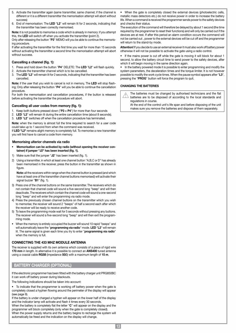
In assenza di tensione di rete il programmatore, se munito del gruppo batterie PRG850BC, può funzionare ugualmente. È necessario osservare quanto segue:
• Perindicareilfunzionamentoabatteria,quandoilcancelloècompletamentechiuso,sul display compare un trattino che scorre lungo il "perimetro esterno" (vedi pagina 3). Se le batterie si scaricassero fino alla soglia di guardia, sul display si avrebbe ugual-mente un trattino in movimento, ma nella metà inferiore del display: in tale situazione la lampada spia verrà attivata ogni 30 secondi circa, effettuando 4 lampeggi. Quando poi la batteria si scarica troppo, sul display compare la lettera "C" e si ha il blocco completo del programmatore (solo con cancello completamente chiuso). Quando la tensione di rete verrà nuovamente fornita, e la tensione di batteria salirà, il sistema si sbloccherà automaticamente, e cambierà anche l’indicazione sul display.• Quandoilcancelloècompletamentechiuso,icarichiesterni(fotocellule,rilevatori
di masse metalliche) non sono alimentati, per aumentare l’autonomia delle batterie; quando viene inviato un comando (via filo o via radio) il programmatore prima di tutto alimenta i carichi e valuta lo stato delle sicurezze. Ne consegue che l’esecuzione del comando, qualora consentita (sicurezze a riposo) verrà ritardata per il tempo neces-sario alla ripresa del corretto funzionamento dei dispositivi stessi (circa 1 secondo). Se dopo tale intervallo di tempo si rileva una sicurezza in allarme, il comando non viene eseguito e l’alimentazione ai carichi esterni viene automaticamente tolta: il programmatore torna in stato di stand-by.
Attenzione!: per quanto detto sopra, se si desidera utilizzare un ricevitore esterno, lo si dovrà alimentare usando sempre la tensione di batteria: soltanto così, infatti, sarà possibile che il comando via radio riesca ad attivare il cancello.
• Selatensionediretevienemenoduranteilmotodelleante,questesibloccherannoper circa un secondo, per permettere che la tensione di batteria possa alimentare cor-rettamente le sicurezze, dopodiché il moto riprenderà nello stesso senso di prima.• Inmodalitàbatteriaècomunquepossibileentrareinprogrammazione,emodificarei parametri del sistema, la selezione del rallentamento e quella della coppia; non è possibile invece programmare i tempi di lavoro. Pertanto, quando comparirà il simbolo "di attesa" (dopo L3) se si preme il tasto "PROG" si uscirà automaticamente dalla procedura di programmazione.
CAMBIO DELLE BATTERIE
Le batterie devono essere cambiate solo da tecnici autorizzati e quelle esauste devono essere smaltite secondo le norme vigenti.Alla fine della vita operativa della centralina, prima di rottamarla negli appositi siti, togliere le batterie e smaltirle separatamente.
CARICA BATTERIA (OPZIONALE)

8
IMPORTANT REMARKS IMPORTANT REMARKS IMPORTANT REMARKS
Programming is carried out using two buttons and allows you to configure the system, set the length of the deceleration stage and set the work and pause times.The intervention of the anticrush/antidrag sensor during the closing and opening stages causes travel direction inversion (if automatic reclosing has been enabled). If activated towards the end of the movement (almost closed) it will act as a travel limit.
Electronic card legendB1 Signal buzzer "via radio" modeDS1 Seven segment displayF1 1A rapid action fuse - 24V circuit overload protection F2 3,15A delayed fuse - electric locking device overload protection (only in
battery powered mode) F3 10A rapid action fuse - motor overload protection F4 10A rapid action fuse - motor overload protection J1 Channel selectionJ2 Enable transmitter memorisation via radio (without opening the container) L1 LED power onL2 LED transmitter code management L3 LED manual operationL4 LED closing travel limit leaf 1 (FCC1)L5 LED opening travel limit leaf 1 (FCA1)L6 LED closing travel limit leaf 2 (FCC2)L7 LED opening travel limit leaf 2 (FCA2)L8 LED TA opening button activatedL9 LED TC closing button activatedL10 LED TB blocking button activateL11 LED FTC_I inverting photoelectric cells activatedL12 LED FTC_S stop photoelectric cells activatedM1 Memory module (300 codes)P1 Programming buttonP2 Selection buttonP3 Transmitter code memorization buttonP4 Transmitter code cancellation buttonR1 433,92 MHz RF module V0-V1 Transformer secondary 1 Faston connection (0-24 Vac) grey-greyVB Battery voltage connection 12 Vdc (only for the electric locking device in
battery powered mode)V2-V3 Transformer secondary 2 Faston connection (0-15 Vac) brown-brownV4-V5 Transformer secondary 3 Faston connection (0-20 Vac) red-red
Attention! Only for EU customers - WEEE marking.This symbol indicates that once the products life-span has expired it must be disposed of separately from other rubbish. The user is therefore obliged to either take the product to a suitable differen-tial collection site for electronic and electrical goods or to send it back to the manufacturer if the intention is to replace it with a new equivalent version of the same product.
Suitable differential collection, environmental friendly treatment and disposal contributes to avoiding negative effects on the ambient and consequently health as well as favouring the recycling of materials.Illicitly disposing of this product by the owner is punishable by law and will be dealt with according to the laws and standards of the individual member nation.
•Before commencing with the installation of this appliance make sure that you have read the following instructions carefully.
In particular familiarise yourself with the safety devices required by the system, only then will you be able to use them to great effect.
•Notallofthesafetydevicesrequiredbythelocalsafetystandardsinforcehave been taken into consideration in this manual. The installer must therefore make sure that any eventual safety devices required by the local standards and regulations have been installed both ahead of and after the products described in this manual.
• Thisappliancemustbeusedexclusively for thepurposeforwhich ithasbeen made. "i.e. for the automation of gates and doors" Any non authorised modifications are to be considered improper and therefore dangerous.
• Theseinstructionsareaimedatprofessionallyqualified"installers of elec-trical equipment" and must respect the local standards and regulations in force.
Attention! The programmer may only be used with motors pro-duced by Cardin Elettronica of the series "BL","HL" and "GL".
Electronic programmer for two direct current motors with an incorporated radio receiver card, which allows the memorisation of or 300 user codes depending on the model (see "remote control" page 12). The 'rolling code' type decoder uses 433,92 MHz. series transmitters. The travel speed is electronically controlled, starting slowly and increasing in speed; the speed is reduced as it nears the travel limit so as to enable a controlled smooth stop (if deceleration hasn’t been excluded during programming).
READ THE FOLLOWING REMARKS CAREFULLY BEFORE PROCEEDING WITH THE INSTALLATION. PAY PARTICU-LAR ATTENTION TO ALL THE PARAGRAPHS MARKED WITH THE SYMBOL . NOT READING THESE IMPOR-TANT INSTRUCTIONS COULD COMPROMISE THE CORRECT WORKING ORDER OF THE SYSTEM AND CREATE DANGER SITUATIONS FOR THE USERS OF THE SYSTEM. SAVE THESE INSTRUCTIONS FOR FUTURE USE.
ELECTRONIC PROGRAMMER
Co
llegam
enti scheda b
ase
PR
G852
19-12-2008
DC
0445D
escription :
Prod
uct Cod
e :
Date:
Draw
ing numb
er :
P.J.Heath
CA
RD
IN E
LE
TT
RO
NIC
A S
.p.A
- 31020 San Vend
emiano
(TV
) Italy - via Raffaello
, 36 Tel: 0438/401818 Fax: 0438/401831
Draft :
All rights reserved
. Unauthorised
copying or use of the inform
ation contained in this d
ocument is p
unishable b
y law
PR
G852
F2 T3.15A
CS1046B DC0344
F1 F1A
2930
P4P3
DELMEMO
L2
DS1
V5
V4
V3
V2
ELS
12V
1098765 161514131211 222120191817 282726252423
LC- O
UT C
H2
LS 24V
CM
N
LP 24V
OU
T 24V
CM
N
FCC
1
FCA
1
FCC
2
FCA
2
TAL
TA TC TD CM
N
CM
N
TB FTC_I
FTC_S
CM
N
F4 F10A
F3 F10A
P2P1
SELPROG L3
L4 L5 L6 L7 L8 L9 L10 L11 L12
L1
VB
V1V0
CHA
CHB
CHC
CHD
CH 1Comando dinamicoDynamic command
Commande dynamiqueDynamische Steuerung
Mando dinámico
Selezione canaliChannel selectionSélection canalKanalwahlSelección
CH 2Comando ausiliarioAuxiliary command
Commande auxiliareHilfssteuerungMando auxiliar
CHA
CHBCHC
CHD
J1
CH
A
CH
B
CH
C
CH
D
M1 M2
2 31 4
R1M1
S449
24C16A)
J2 J2
B1
SPR
1
9
•Beforeconnectingtheappliancemakesurethatthevoltageandfre-quency rated on the data plate conform to those of the mains supply.
WARNING! An omnipolar trip switch with a least 3mm between the contacts must be installed between the unit and the mains supply.
• Connectthecontrolandsecuritydevicewires.• Connectthepowersupplycabletothedeviceusingtheterminalblock(whichis
already connected to the transformer primary, white wire).• Donotusecableswithaluminiumconductors;donotsoldertheendsofcables
which are to be inserted into the binding posts; use cables which are marked T min 85°C and are resistant to atmospheric agents.
• Theterminalwiresmustbepositionedinsuchawaythatboththewireandtheinsulating sheath are tightly fastened. Where possible use the supplied cable clamp.
Terminal board connection 1-2 Motor 1 output: Opening: live at binding post "1" and negative at binding post "2" Closing: Negative at binding post "1" and live at binding post "2"3-4 Motor 2 output: Opening: live at binding post "3" and negative at binding post "4" Closing: Negative at binding post "3" and live at binding post "4"5 Common for all inputs and outputs6 Output for electric locking device (continuously powered) 12 Vdc - 15 W;
it must be garage door type lock (not automatically resetting) as it is only activated for 1 second.
7-8 Potential free digital output (contact normally open) for the night light (powered separately by: Vmax= 30Vac/dc; Imax= 1A) or for the second radio channel. Selection is made during programming.
9 Indicator light output 24 Vac 3 W 10 24 Vac 10 W output warning lights (intermittent or continuous activation)11 24 Vac 10 W output, powering external devices.12-13 Common for all inputs and outputs14 FCC1 (normally closed contact) closing travel limit switch leaf 115 FCA1 (normally closed contact) opening travel limit switch leaf 116 FCC2 (normally closed contact) closing travel limit switch leaf 217 FCA2 (normally closed contact) opening travel limit switch leaf 218 TAL (normally open contact) limited opening button 19 TA (normally open contact ) Opening button input20 TC (normally open contact ) Closing button input21 TD (normally open contact ) for the sequential command (open, block, close,
block or open, close with travel direction inversion only during closing accord-ing to the program settings).
22-23 Common for all inputs and outputs24 TB (normally closed contact) blocking button input (The opening of this
contact interrupts the cycle until a new movement command is given)25 FTC_I (normally closed contact) Safety and control devices in input (photocells
invert the travel direction when an obstruction is detected). The opening of this contact will provoke a travel direction inversion during closure due to the cutting in of the safety device.
26 FTC_S (normally closed contact) Safety and control devices in input (stop photoelectric cells). The opening of this contact will block all movement, until the obstruction has been removed, due to the safety device cutting in, the door will then continue moving until it reaches a travel limit (only in the automatic mode).
27-28 Common for all inputs and outputs29 Pole for radio receiver antenna; connect a 17cm piece of rigid wire or an
external antenna ANS400 using coaxial cable RG58 (with an impedance of 50Ω)30 Mass for radio receiver antenna
Note: ALL UNUSED NORMALLY CLOSED CONTACTS MUST BE BRIDGED(It is not necessary for travel limits excluded via software during programming)Switch on the power and make sure that the red indicator LED are in the following condition:
- L1 Power on LED on- L4 Safety LED for the closing travel limit leaf 1 "FCC1" on*- L5 Safety LED for the opening travel limit leaf 1 "FCA1" on*- L6 Safety LED for the closing travel limit leaf 2 "FCC2" on*- L7 Safety LED for the opening travel limit leaf 2 "FCA2" on*- L8 Safety LED opening button "TA" off- L9 Safety LED closing button "TC" off- L10 Safety LED for the blocking button "TB" on*- L11 Safety LED for the inversion photo electric cells "FTC_I" on*- L12 Safety LED for the stop photo electric cells "FTC_S" on*
* The LEDs are "ON" if the relative security device is inactive (depends on the position of the door and the presence of the relative safety device). Check that the activation of the safety devices switches off the corresponding LEDS. If the power on LED "L1" doesn't light up check the condition of the fuse "F1" and the 230V~ power cable connection.If one or more of the safety LEDS do not light up check the contacts of the rela-tive security devices and check that the unused safety device contacts have been bridged.
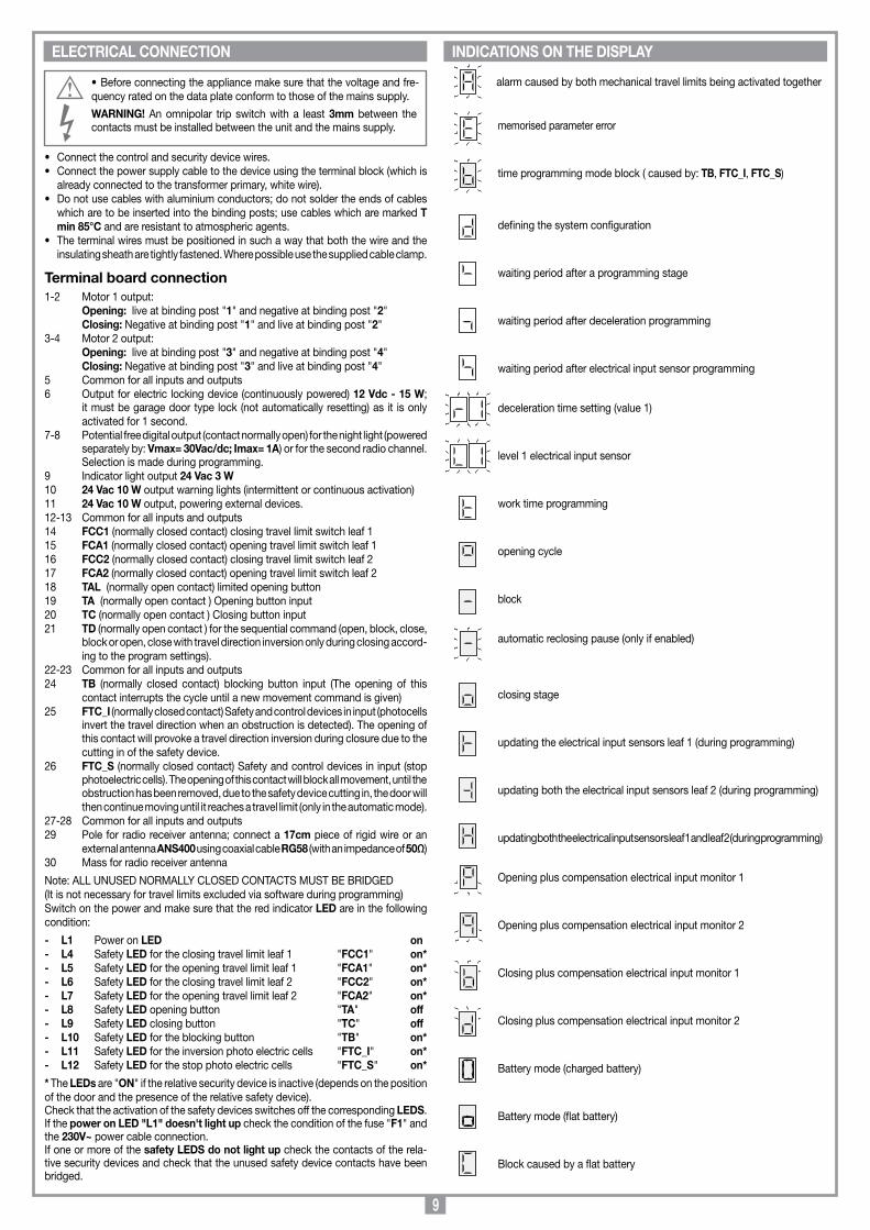
alarm caused by both mechanical travel limits being activated together
memorised parameter error
time programming mode block ( caused by: TB, FTC_I, FTC_S)
defining the system configuration
waiting period after a programming stage
waiting period after deceleration programming
waiting period after electrical input sensor programming
deceleration time setting (value 1)
level 1 electrical input sensor
work time programming
opening cycle
block
automatic reclosing pause (only if enabled)
closing stage
updating the electrical input sensors leaf 1 (during programming)
updating both the electrical input sensors leaf 2 (during programming)
updating both the electrical input sensors leaf 1 and leaf 2 (during programming)
Opening plus compensation electrical input monitor 1
Opening plus compensation electrical input monitor 2
Closing plus compensation electrical input monitor 1
Closing plus compensation electrical input monitor 2
Battery mode (charged battery)
Battery mode (flat battery)
Block caused by a flat battery
ELECTRICAL CONNECTION INDICATIONS ON THE DISPLAY

10
Before commencing make sure that the doors/gates are closed, the LCD display is off and the LEDS L10, L11, L12 are all lit.
LED L4 and L6 (if the closing direction travel limits for leaves 1 and 2 have been installed) are off (closing travel limit activated)
PROGRAMMING PROCEDURE (Setting the programmer, the current sensor and the work times)
SEL
PRESSPROG
Singlemotor
Hingedgates
Slidinggates
ACTIVEFUNCTION
Binding posts 7,8courtesy light
Binding posts 7,8CH2 radio control
TD: open-close
TD: open-blockclose-block
Preflashingenabled
Preflashingdisabled
Motor 1travel limitenabled
Motor 1travel limitdisabled
DS1PRESS THE PROG BUTTON FOR MORE THAN 4 SECONDS: THE PARAMETER DEFINITION LETTER "d" WILL APPEAR ON THE DISPLAY (STAGE "A")
ACTIVEFUNCTION
PRESSSEL
1...20 s
WAIT FOR ABOUT 20 SECONDS WITHOUT PRESSING ANY BUTTONS: THE PROGRAMMER WILL SAVE THE PARAMETERS SET UP TO NOW AND WILL QUIT PROGRAMMING.
AFTER 1 SECOND THE DIGIT "1" WILL APPEAR (FIRST PROGRAMMING STEP). THIS NUMBER CAN BE EITHER FLASHING OR FIXED
Note 1
Electric lockenabled
Electric lockdisabled
Automaticreclosingenabled
Automaticreclosingdisabled
PRESSING "PROG" WILL TAKE YOU TO STAGE "C". PROGRAMMING THE CURRENT SENSOR. THE VALUES RANGE FROM 1 TO 3.
Double motor
PRESS SEL
Motor 2travel limitenabled
Motor 2travel limitdisabled
Warning lightswith onboardelectronics
Warning lightsactivatedby PRG
Decelerationenabled
Decelerationdisabled
Non flashingindicator
light
Flashingindicator light
FTC_Ienabled withgate blocked
FTC_Ienabled only
during closing
PRESSPROG
Note 2
Nota 3
Note 1 Travel direction inversion only active during the closing stage. Note 2 The indicator light flashes slowly during opening, quickly during closing,
remains open when the gate is not completely closed, and is off when the gate is completely closed.
Note 3 If the photoelectric cell is in alarm and the gate is blocked no movement commands will be accepted (not even in the opening direction).
PRESSPROG
PRESS SEL
PRESSPROG
PRESS SEL
PRESSPROG
PRESS SEL
PRESSPROG
PRESS SEL
PRESSPROG
PRESS SEL
PRESSPROG
PRESS SEL
PRESSPROG
PRESS SEL
PRESSPROG
PRESS SEL
PRESSPROG
PRESS SEL
PRESSPROG
PRESS SEL
PRESSPROG
PRESS SEL
PRESSPROG
PRESSSEL
ALTERNATING
PRESSPROG
PRESSPROG
ALTERNATING
PRESSPROG
FIXEDVALUE
PRESSSEL
ALTERNATINGFIXEDVALUE
PRESSSEL
FIXEDVALUE
selection3 seconds
selection4,5 seconds
selection6 seconds
PRESSPROG
PRESSSEL
WAIT FOR ABOUT 20 SECONDS WITHOUT PRESSING ANY BUTTONS: THE PROGRAMMER WILL SAVE THE PARAMETERS SET UP TO NOW AND WILL QUIT PROGRAMMING.
Attention! The R1, R2 and R3 selection must be carried out even if deceleration is excluded: The time during which the electrical sensor works as a travel limit in the last few seconds of movement must be decided upon. You are advised to set a time of 4,5 seconds.The choice should be made to enable a smooth stop with slow speed only being used where absolutely necessary.
1...20 s
PRESSSEL
ALTERNATING
PRESSPROG
PRESSPROG
ALTERNATING
PRESSPROG
FIXEDVALUE
PRESSSEL
ALTERNATINGFIXEDVALUE
PRESSSEL
FIXEDVALUE
minimumtorque
mediumtorque
maximumtorque
PRESSPROG
PRESSSEL
WAIT FOR ABOUT 20 SECONDS WITHOUT PRESSING ANY BUTTONS: THE PROGRAMMER WILL SAVE THE PARAMETERS SET UP TO NOW AND WILL QUIT PROGRAMMING.
Attention The programmer checks the electrical input to the motor, detecting any eventual increase in effort above the normal operating limits. To guarantee correct operation even under various climatic and mechanical conditions, the programmer recalibrates itself each time it receives an opening command from the "completely closed" position. This allows the system to detect any increase in effort which wasn't present during programming and to compensate so that the force required to block the door remains constant, so guaranteeing optimum operation (see "compensation of the electrical sensors" page 12.
PRESSING "PROG" WILL TAKE YOU TO STAGE "B". PROGRAMMING THE DECELERATION TIMES. THE VALUES RANGE FROM 1 TO 3.
PRESSING "PROG" WILL TAKE YOU TO THE FINAL STAGE "D". PROGRAMMING THE WORK TIMES.
CONTINUE ON PAGE 11

11
Press prog to starta programming cyclewith:
- Two sliding gates-
Press prog to starta programming cyclewith:
In stage “A” step “1” you have selected the parameter “single motor”
YES
Open gate leaf 1
End pause time count (start closing cycle )
YES NO
Press prog before gate leaf 1 reaches the travel limit. End calibration sensor 1(opening direction)
When the gate reaches the mechanical stop or reaches the opening travel limit the pause time count will start.
Close gate leaf 1
Open gate leaves 1 and 2
Open gate leaves 1 and 2
PRESS PROG
The end of programming is indicated by the courtesy light switching on and thedisplay switching off.
PRESS PROG
Open gate leaf 1 and after 2 seconds (out of synchronism movement) gate 2 will start
PRESS PROG
Press prog before gate leaf 2 reaches the travel limit. End calibration sensor 2 (opening direction)
When both the gates reach the mechanical stop or both reache the opening travel limit the pause time count will start.
PRESS PROG
PRESS PROG
The end of programming is indicated by the courtesy light switching on and thedisplay switching off.
PRESS PROG
DS1
In stage “A” step “2” you have selected the parameter “Sliding gates”
PRESS PROG
PRESS PROG
PRESS PROG
Press prog before gate leaf 1 reaches the travel limit. End calibration sensor 1(closing direction)
PRESS PROG
The end of programming is indicated by the courtesy light switching on and thedisplay switching off.
PRESS PROG
PRESS PROG
PRESS PROG
DS1
PRESS PROG
Press prog before gate leaf 1 reaches the travel limit. End calibration sensor 1(opening direction)
Press prog before gate leaf 2 reaches the travel limit. End calibration sensor 2 (opening direction)
End pause time count (start closing cycle )
Press prog before gate leaf 2 reaches the travel limit. End calibration sensor 2(closing direction)
Press prog before gate leaf 1 reaches the travel limit. End calibration sensor 1(closing direction)
PRESS PROG
Press prog before gate leaf 1 reaches the travel limit. End calibration sensor 1(opening direction)
End pause time count start closing cycle gate 2
Close gate leaf 2
PRESS PROG
Close gate 1End closing synchonism movement - Note 2 -
Press prog before gate leaf 1 reaches the travel limit. End calibration sensor 1(closing direction)
Press prog before gate leaf 2 reaches the travel limit. End calibration sensor 2(closing direction)
DS1
Note 1: Selecting a single gate (gate1) automatically disables the travel limits for gate 2.Excluding travel limits during programming means you will not have to bridge the contacts on the terminal board.
NO
- Single motor -
When both the gates reach the mechanical stop or both reache the opening travel limit the pause time count will start.
Press prog to starta programming cyclewith:
- Two hinged gates-
PRESS PROG
CONTINUED FROM PAGE 10 STAGE "D" PROGRAMMING THE WORK TIMES
Programming is carried out step by step by the system which activates the motors according to the settings carried out in the previous step (e.g.: If you have chosen a 1 gate configuration, only motor number 1 will be acti-vated). If the electric locking device, preflashing and gate jolt (initial movement in the closing direction) have been enabled, they must also be set during programming.
- Note 2 - The maximum closing direction delay time for gate 1 is equal to the work time of gate 2. • Ifyouwishtoexitprogrammingwithoutmemorising the time elapsed press the "SEL"button. The gates will block and only the system definition parameters will be memorisedincluding the deceleration and electrical sensor settings. •Theinterventionofthetraveldirectioninversionorblockingphotocellorpressingtheblock-ing button will stop the gate, while the flashing warning light will remain lit, indicating that the programmer is in an active phase. The figure "b" will flash on the display.The work time count is blocked, but once the alarm situation has been resolved or the blocking button has been released (only active while it is being pressed down) the gate movement will start up again automatically, and the time count will carry on. •Theinterventionofamechanicaltravellimitortheelectricalinputsensorwillcausethegateleaftostopandtheworkcycletimetoexpire.WARNING! Program the work time so that the gate always opens completely, otherwise the completion of the manoeuvre cannot be guaranteed (see paragraph "timer travel limits").

12
1) Automatic Selected by enabling automatic reclosing (programming step 6, number "6" not flash-ing). When the door is completely closed the opening command will start a complete cycle which will end with automatic reclosing and the night light switching off.Automatic reclosing starts after the programmed pause period has elapsed when the opening cycle has been completed or straight away after the intervention of a photoelectric cell (the intervention of a photoelectric cell causes the pause time to be reset). During the pause time the symbol will flash on the display and pressing the blocking button during this period will stop automatic reclosing and consequently stop the display from flashing. The intervention of the mechanical travel limits or the electrical sensor will block the door/gate. The indicator light remains lit until the closing manoeuvre has terminated.Note: the night light switches on automatically each time a movement command is given either by control button or by radio. The intervention of a photoelectric cell during reclosing has no effect on the timing of the night light.
2) SemiautomaticSelected by disabling automatic reclosing (programming step "6", number "6" flash-ing). Work cycle control using separate opening and closing commands. When the door has reached the completely open position the system will wait until it receives a closing command either via an external control button or via radio control, before completing the cycle. The activation of one of the travel limit switches causes the door to stop and the termination of the opening/closing cycle. Starting from the opening manoeuvre the night light will switch off after the set period has elapsed. The indicator light remains lit until the closing manoeuvre has terminated.
LIMITED OPENINGThis only effects gate 1; If a double gate leaf system has been selected, gate leaf 1 will open completely. If a single gate leaf system has been selected, gate leaf 1 will open for about a third of its opening angle (pedestrian function). The command can only be carried out with the gate leaves completely closed; if you press "TAL" again during opening leaf 1 will block and the next command will send it in the closing direction. At this point the command can only be used after the gates leaves are once again completely closed.
COURTESY LIGHT/SECOND RADIO CHANNEL CH2Binding posts "7","8" are wired to the C-N0 contacts of a relay. This function can be activated as a normal "courtesy light" (normally closed contact) for the programmed period of time or may be used as second radio control channel selected on the inte-grated decoder (jumper "J1"). Binding posts "7","8" have a direct contact and as it does not output any voltage it only functions as a simple switch. This means that an eventual night light must receive its power externally.
Attention! There is no 230Vac connection on the main circuit board (only the low voltage 24V circuit is present. The standards and regulations in force regarding the isolation of low (24Vac) and high voltage circuits (230Vac) means that you must not directly connect a device which applies a voltage of 230Vac to the binding posts "7" and "8".
MANUAL OPERATION MODEThis can be used to close the door (or open it) under the direct control of the operator (in this mode the security devices FTC_I, FTC_S and TB only intervene when they are in alarm). The aim of this command is to make installation easier and to allow you to have the door completely closed before starting the programming procedure. In this mode the LED "L3" (marked "UPL") will remain lit. The "manual mode" can also be used while working off battery power; the motors are supplied with the maximum voltage (turnover speed) whether or not deceleration has been programmed. The FTC_I (only in the closing direction regardless of the selection made at step "C" during program-ming ) and FTC_S safety devices are managed in the same way as for the travel limits and the electrical input sensors.
•ClosingmanoeuvreThis is obtained by pressing the button "SEL". The motor will block in the closing direction due to:- releasing the "SEL" button (takes you out of the "manual operation mode").- activating the blocking button "TB": to move the door again you must first release
the "SEL" button and then press it again.- activating the closing direction travel limit (if installed): pressing the "SEL" button
will not cause the door to close, but it will switch the night light on.
•OpeningmanoeuvreThis is obtained by pressing the button "SEL", and then the "PROG" button straight away. The motor will block in the opening direction due to:- releasing both buttons (takes you out of the "manual operation mode").- activating the blocking button "TB": to move the door again you must first release
both buttons and then press them again.- activating the opening direction travel limit.
FUNCTION MODES •TraveldirectioninversionIf the door is closing: to enable an opening manoeuvre: press the "PROG" buttonIf the door is opening: to enable a closing manoeuvre: release the "PROG" button
• Night lightThe night light remains on all the time while in the "manual operation mode"; it also lights up when an opening or closing command is given but the travel limit blocks the command.
ELECTRICAL INPUT SENSOR COMPENSATIONMeasuring the electrical input of the motors is carried out in order to be able to com-pensate for any small variations caused by environmental conditions; Should this occur a flashing hyphen will appear on the display (the quicker it flashes the greater the compensation required). The hyphen will appear on the left of the display for sensor "1" and on the right of the display for sensor "2" (see "Indications on the display" page 9).Each time the movement is blocked (even the inversion command) the compensation factor will be reset and recalculated so as to be continuously updated.
ALARM CONDITIONS
1) Parameters loaded from EEPROM are wrongThe letter , will flash on the display and the system remains blocked. The only way to solve this situation is to enter the program mode and reprogram the system. If the problem persists after reprogramming, the problem regards the EEPROM (incor-rect memorising). Switch off the power to the system, after a few seconds switch it back on and then reprogram the system.
2) Both travel limits have cut in simultaneously. The letter , will appear on the display and the system remains blocked. The warning lights will flash for a three second period which is repeated every six seconds. The only way to solve this problem is to check the travel limits for obstacles or damage and then restart the system.
TIMER CONTROLLED TRAVEL LIMITSThe work time management allows the system to control the position of the gate. During blackouts the programmer will lose the position of the gate which will be considered to be "completely closed", unless the completely open travel limit is active this is so as to allow the opening manoeuvre. The work times are programmed in this transitory phase in such a way as to guarantee the complete opening of the door and successively complete closing.After repetitive travel inversion manoeuvres, with the motor stopping then restarting slowly, you may find that the time control is false and the device does not decelerate before arriving at the travel limit. The time control will be reset at the next manoeuvre.
The motor can be remotely activated using a transmitter: only the sequential func-tion is available "open-block-close-block" and this may be activated from any of the available channels.If you select number "3" flashing during system parameter definition a second radio control channel will be available with a C-NO contact at binding posts "7","8".
Memory module This is extractable, furnished with a non volatile EEPROM type memory and contains the transmitter codes and allows you to memorise up to 300 codes (300 channel buttons). The programmed codes are maintained in this module even in the absence of power.
Before memorising the transmitters for the first time remember to cancel the entire memory content.
Attention! If the electronic card has to be replaced due to failure, the module can be extracted from it and inserted into the new card. Make sure that the module is orientated in the direction shown in fig.1 detail A.
TRANSMITTER CODE MANAGEMENT
Signal LEDs "L2" (fig.1): Flashing quickly: cancels a single codeFlashing slowly: memorises a single codePermanently lit: memory full.
Memorising a channel (fig.1):1. Press and hold down button "P3" MEMO: The LED "L2" will flash slowly.2. At the same time activate the transmitter which is to be memorised.3. Hold down button "P3" MEMO until LED "L2" starts to flash again.4. Release the button: The LED will continue to flash.
REMOTE CONTROL S449
13
5. Activate the transmitter again (same transmitter, same channel; if the channel is different or it is a different transmitter the memorisation attempt will abort without success)
6. End of memorisation: The LED "L2" will remain lit for 2 seconds, indicating that the transmitter has been correctly memorised.
Note: it is not possible to memorise a code which is already in memory: if you attempt this, the LED will switch off when you activate the transmitter (point 2). Only after releasing the button "P3" MEMO will you be able to continue the memoris-ing procedure. If after activating the transmitter for the first time you wait for more than 15 seconds without activating the transmitter a second time the memorisation attempt will abort without success.
Cancelling a channel (fig. 1):1. Press and hold down the button "P4" DELETE: The LED "L2" will flash quickly.2. Activate the transmitter channel which is to be cancelled.3. The LED "L2" will remain lit for 2 seconds, indicating that the transmitter has been
cancelled.
Note: if the user that you wish to cancel is not in memory, The LED will stop flash-ing; Only after releasing the button "P4" will you be able to continue the cancellation procedure.For both the memorisation and cancellation procedures, if the button is released before activating the transmitter the procedure will abort.
Cancelling all user codes from memory (fig. 1):1. Keep both buttons pressed down ("P3 + P4") for more than four seconds2. LED "L2" will remain lit during the entire cancellation time (about 8 seconds).3. LED "L2" switches off when the cancellation procedure has terminated.
Note: when the memory is almost full the time required to search for a user code could take up to 1 second from when the command was received.If LED "L2" remains alight memory is completely full. To memorise a new transmitter you will first have to cancel a code from memory.
Memorising ulterior channels via radio • Memorisation can be activated by radio (without opening the receiver con-
tainer) if jumper "J2" has been inserted (fig. 1).
1) Make sure that the jumper "J2" has been inserted (fig. 1).
2) Using a transmitter, in which at least one channel button "A,B,C or D" has already been memorised in the receiver, press the button in the transmitter as shown in figure.
Note: all the receivers within range when the channel button is pressed (and which have at least one of the transmitter channel buttons memorised) will activate their signal buzzer "B1" (fig. 1).
3) Press one of the channel buttons on the same transmitter. The receivers which do not contain that channel code will sound a five-second long "beep" and will then deactivate. The receivers which contain the channel code will sound a one-second long "beep" and will enter the programming via radio mode.
4) Press the previously chosen channel buttons on the transmitter which you wish to memorise; the receiver will sound 2 "beeps" of half a second each after which the receiver will be ready to receive another code.
5) To leave the programming mode wait for 5 seconds without pressing any buttons. The receiver will sound a five-second long "beep" and will then exit the program-ming mode.
• Whenthememoryisentirelyoccupiedthebuzzerwillsound10rapid"beeps"andwill automatically leave the "programming via radio" mode. LED "L2" will remain lit. The same signal is given each time you try to enter "programming via radio" when the memory is full.
CONNECTING THE 433 MHZ MODULE ANTENNA The receiver is supplied with its own antenna which consists of a piece of rigid wire 170 mm in length. In alternative it is possible to connect an ANS400 tuned antenna using a coaxial cable RG58 (impedance 50Ω) with a maximum length of 15 m.
If the electronic programmer has been fitted with the battery charger unit PRG850BC it can work off battery power during blackouts.
The following indications should be taken into account:
• Toindicatethattheprogrammerisworkingoffbatterypowerwhenthegateiscompletely closed a hyphen flowing around the perimeter of the display will appear (see page 9). If the battery is under charged a hyphen will appear on the lower half of the display and the indicator lamp will activate and flash 4 times every 30 seconds.When the battery is completely flat the letter "C" will appear on the display and the programmer will block completely (only when the gate is completely closed). When the power supply returns and the battery begins to recharge the system will automatically be freed and the indication on the display will change.
BATTERY CHARGER (OPTIONAL)
• Whenthegate iscompletelyclosedtheexternaldevices (photoelectriccells,metallic mass detectors etc.) do not receive power in order to increase the battery life. When a command is received the programmer sends power to the safety devices and checks their status.The execution of the command will therefore be delayed by about 1 second (the time required by the programmer to reset their functions) and will only be carried out if the devices are at rest. If after this period an alarm condition occurs the command will not be carried out , power to the external devices will be cut off and the programmer will return to the stand-by mode.
Attention! If you decide to use an external receiver it must also work off battery power otherwise it will not be possible to activate the gate using a radio control.
• Ifthemainspoweriscutoffwhilethegateismovingitwillblockforabout1second, to allow the battery circuit time to send power to the safety devices, after which it will begin moving in the same direction again.• Inthebatterypoweredmodeitispossibletoenterprogrammingandmodifythesystem parameters, the deceleration times and the torque limiter. It is not however possible to modify the work cycle times. When the pause symbol appears after "L3", pressing the "PROG" button will force the program to quit.
CHANGING THE BATTERIES
The batteries must be changed by authorised technicians and the flat batteries are to be disposed of according to the local standards and regulations in course. At the end of the control unit's life span and before disposing of the unit makes sure you remove the batteries and dispose of them separately.

14
CONSIGNES IMPORTANTES! CONSIGNES IMPORTANTES! CONSIGNES IMPORTANTES!
LIRE ATTENTIVEMENT LES CONSIGNES SUIVANTES AVANT DE PROCÉDER À LA POSE. PRÊTER GRANDE ATTENTION À TOUTES LES SIGNALISATIONS QUI SE TROUVENT DANS LE TExTE. LE NON RESPECT DE CES CONSIGNES POURRAIT COMPROMETTRE LE BON FONCTIONNEMENT DU SYSTÈME. CONSERVER CES INSTRUCTIONS POUR RÉFÉRENCES FUTURES.
PROGRAMMATEUR ÉLECTRONIQUE
Co
llegam
enti scheda b
ase
PR
G852
19-12-2008
DC
0445D
escription :
Prod
uct Cod
e :
Date:
Draw
ing numb
er :
P.J.Heath
CA
RD
IN E
LE
TT
RO
NIC
A S
.p.A
- 31020 San Vend
emiano
(TV
) Italy - via Raffaello
, 36 Tel: 0438/401818 Fax: 0438/401831
Draft :
All rights reserved
. Unauthorised
copying or use of the inform
ation contained in this d
ocument is p
unishable b
y law
PR
G852
F2 T3.15A
CS1046B DC0344
F1 F1A
2930
P4P3
DELMEMO
L2
DS1
V5
V4
V3
V2
ELS
12V
1098765 161514131211 222120191817 282726252423
LC- O
UT C
H2
LS 24V
CM
N
LP 24V
OU
T 24V
CM
N
FCC
1
FCA
1
FCC
2
FCA
2
TAL
TA TC TD CM
N
CM
N
TB FTC_I
FTC_S
CM
N
F4 F10A
F3 F10A
P2P1
SELPROG L3
L4 L5 L6 L7 L8 L9 L10 L11 L12
L1
VB
V1V0
CHA
CHB
CHC
CHD
CH 1Comando dinamicoDynamic command
Commande dynamiqueDynamische Steuerung
Mando dinámico
Selezione canaliChannel selectionSélection canalKanalwahlSelección
CH 2Comando ausiliarioAuxiliary command
Commande auxiliareHilfssteuerungMando auxiliar
CHA
CHBCHC
CHD
J1
CH
A
CH
B
CH
C
CH
D
M1 M2
2 31 4
R1M1
S449
24C16A)
J2 J2
B1
SPR
La programmation, réalisable par deux seuls boutons, permet la confi-guration du système, de la durée de la phase de ralentissement, des senseurs d'effort et des temps de travail-arrêt. L'intervention du senseur anti-coincement en phase de fermeture provoque l'inversion du mouvement; ceci se produit également en phase d'ouverture si la refermeture automati-que a été validée sinon elle provoque seulement l'arrêt. Par contre, en phase terminale de la manœuvre, le senseur remplit la fonction de fin de course.
Descriptif de la carte électroniqueB1 Avertisseur sonore de signalisation mode "par radio"DS1 Afficheur à 7 segmentsF1 Fusible 1A rapide - protection contre les surcharges ligne à 24 V F2 Fusible 3,15A retardé - protection contre les surcharges alimentation serrure
électrique (uniquement pour le fonctionnement à batterie) F3 Fusible 10A rapide - protection contre les surcharges alimentation
moteurs F4 Fusible 10A rapide - protection contre les surcharges alimentation
moteurs J1 Sélection des canauxJ2 Validation de la mémorisation par radio (sans ouvrir le boîtier)L1 LED carte alimentéeL2 LED de gestion codes (émetteur)L3 LED mode manuelL4 LED de signalisation fin de course fermeture du vantail 1 (FCC1)L5 LED de signalisation fin de course ouverture du vantail 1 (FCA1)L6 LED de signalisation fin de course fermeture du vantail 2 (FCC2)L7 LED de signalisation fin de course ouverture du vantail 2 (FCA2)L8 LED de signalisation TAL9 LED de signalisation TCL10 LED de signalisation TBL11 LED de signalisation FTC_IL12 LED de signalisation FTC_SM1 Module de mémoire (300 codes)P1 Touche de programmationP2 Touche de sélectionP3 Touche de mémorisation code émetteur P4 Touche d'annulation code émetteurR1 Module RF à 433.92 MHz V0-V1 Connexion au secondaire 1 du transformateur (0-24 Vac) gris-grisVB Connexion à la tension de batterie 12 Vdc (uniquement pour fonctionnement
serrure électrique en mode fonctionnement à batterie)V2-V3 Connexion au secondaire 2 du transformateur (0-15 Vac) marron-marronV4-V5 Connexion au secondaire 3 du transformateur (0-20 Vac) rouge-rouge
Attention! Seulement pour les clients de l'EU - Marquage WEEE.Ce symbole indique l’obligation de ne pas éliminer l’appareil, à la fin de sa durée de vie, avec les déchets municipaux non triés et de procéder à sa collecte sélective. Par conséquent, l’utilisateur doit remettre l’appareil à un centre de collecte sélective des déchets électroniques et électriques ou au revendeur qui est tenu, lorsqu’il fournit un nouvel appareil, de faire en sorte que les déchets puissent lui être remis, sur une base de un pour un, pour autant que l’appareil soit de type équivalent à celui qu’il fournit.
La collecte sélective des équipements électriques et électroniques en vue de leur valorisation, leur traitement et leur élimination dans le respect de l’environnement contribue à éviter la nocivité desdits équipements pour l’environnement et pour la santé et à encourager leur recyclage. L’élimination abusive de l’équipement de la part du détenteur final comporte l’application des sanctions administratives prévues par les normes en vigueur dans l’État Membre d’appartenance.
• Avantdeprocéderàl'installation, lireattentivementcelivret.Enparticulier,sefamiliariser avec les dispositifs de sécurité prévus sur le produit afin de pouvoir les utiliser au mieux.
• Nontouslesdispositifsdesécurité,renduséventuellementobligatoiresparlesnormes en vigueur, ne sont pris en considération dans ce livret. L'installateur devra y remédier personnellement en installant les dispositifs manquants en amont ou en aval des produits décrits dans ce livret.
• Unediverseutilisationdesproduitsouleurdestinationàunusagedifférentdeceuxprévus et/ou conseillés n'a pas été expérimentée par le fabricant. Par conséquent, les travaux effectués sont entièrement sous la responsabilité de l'installateur.
• Celivretestdestinéàdespersonnestitulairesd'uncertificatd'aptitudeprofes-sionnelle pour l'installation des "Appareils électriques" et requiert une bonne connaissance de la technique appliquée professionnellement. Le Constructeur décline toute responsabilité pour les éventuels dommages entraînés par la non observation des normes de sécurité en vigueur actuellement durant l'installation des appareils.
Attention! Le programmateur ne peut être utilisé qu'avec Cardin moteurs de la gamme "BL","HL" et "GL".
Programmateur pour deux moteurs à courant continu avec récepteur intégré permettant la mémorisation de 300 codes usager selon le modèle (voir "Commande par radio" à la page 17). Le système fonctionne sur la bande de fréquence 433 MHz.Contrôlée électroniquement, la vitesse de rotation des moteurs est lente au départ pour augmenter successivement; elle est réduite avant l'arrivée au fin de course de façon à obtenir un arrêt contrôlé (si le ralentissement n'a pas été invalidé lors de la programmation).

15
Avant d'effectuer le branchement électrique, contrôler que la tension et la fréquence indiquées sur la plaquette signalétique correspondent aux données du réseau d'alimentation électrique.Il est impératif d'installer entre l'armoire de commande et le réseau un interrupteur omnipolaire ayant une distance d'ouverture des contacts d'au moins 3 mm.
• Brancherlesfilsdescommandesetceuxquiproviennentdesdispositifsdesécurité.• Brancherlecâbled'alimentationaudispositifaumoyenduborniervolant(quiest
déjà raccordé au primaire du transformateur, fils blanc-noir).• Nepasutiliserdecâbleavecconducteursenaluminium;nepasétamerl'extrémité
desfilsàbranchersurlebornier;utiliseruncâblemarquéT min. 85°C et résistant aux agents atmosphériques.
• Lesconducteursdevrontêtrefixésàproximitédubornierdetellefaçonquelafixation maintienne aussi bien l'isolation que le conducteur (il suffit d'un collier).
Branchement du bornier 1-2 Sortie pour moteur 1: en ouverture: positif sur borne 1 et négatif sur borne 2 en fermeture: négatif sur borne 1 et positif sur borne 23-4 Sortie pour moteur 2: en ouverture: positif sur borne 3 et négatif sur borne 4 en fermeture: négatif sur borne 3 et positif sur borne 45 Communs pour toutes les entrées et les sorties6 Sortie pour serrure électrique (pilotée en continu) 12 Vdc 15 W; elle doit être de
type basculant (non à réarmement automatique) du fait que l'activation dure 1 s.7-8 Sortie (contact non alimenté, N.O) pour activation éclairage de zone (alimenté
séparément, Vmax= 30Vac/dc; Imax= 1A) ou pour deuxième canal radio. La sélection s'effectue lors de la programmation.
9 Sortie lampe témoin 24 Vac 3 W 10 Sortie clignoteur 24 Vac 10 W (activation continue ou intermittente)11 Sortie pour alimentation charges externes 24 Vac 10 W 12-13 Communs pour toutes les entrées et les sorties14 FCC1 (contact N.F.) entrée fin de course en fermeture vantail 115 FCA1 (contact N.F) entrée fin de course en ouverture vantail 116 FCC2 (contact N.F.) entrée fin de course en fermeture vantail 217 FCA2 (contact N.F) entrée fin de course en ouverture vantail 218 TAL (contact N.O.) entrée bouton d'ouverture partielle 19 TA (contact N.O.) entrée bouton d'ouverture20 TC (contact N.O.) entrée bouton de fermeture21 TD (contact N.O.) entrée pour commande séquentielle (ouvre-arrêt-ferme-
arrêt) ou ouvre-ferme avec inversion seulement en fermeture, selon les programmations du programme).
22-23 Communs pour toutes les entrées et les sorties24 TB (contact N.F.) entrée bouton de blocage25 FTC_I (contact N.F.) entrée pour dispositifs de sécurité (cellule photoélec-
trique d'inversion en fermeture). L'ouverture du contact durant la phase de fermeture, suite à une intervention des dispositifs de sécurité, provoquera l'inversion du mouvement.
26 FTC_S (contact N.F.) entrée pour dispositifs de sécurité (cellule photoélec-trique d'arrêt). Le mouvement de fermeture reprend automatiquement au retour à la condition de veille, après le temps d'arrêt (uniquement en mode de fonctionnement automatique).
27-28 Communs pour toutes les entrées et les sorties29 Âme antenne récepteur radio (brancher un fil rigide de 17 cm ou une antenne
externe ANS400moyennantuncâblecoaxialRG58 imp. 50Ω).30 Masse antenne récepteur radio
N.B.: FAIRE UN PONT SUR TOUS LES CONTACTS N.F. INUTILISÉS(pas nécessaire pour les fins de course invalidés lors de la programmation)Alimenter le circuit et contrôler que l'état des LEDs rouges de signalisation soit conforme aux indications ci-dessous:- L1 LED de mise sous tension du circuit allumé- L4 LED de fin de course en fermeture vantail 1 "FCC1" allumé*- L5 LED de fin de course en ouverture vantail 1 "FCA1" allumé*- L6 LED de fin de course en fermeture vantail 2 "FCC2" allumé*- L7 LED de fin de course en ouverture vantail 2 "FCA2" allumé*- L8 LED de signalisation touche d'ouverture "TA" éteint- L9 LED de signalisation touche de fermeture "TC" éteint- L10 LED de sécurité touche de blocage "TB" allumé*- L11 LED de sécurité cellules photoél. d'inversion "FTC_I" allumé*- L12 LED LED de sécurité cellules photoél. d'arrêt "FTC_S" allumé** Les LEDS sont allumés si le relatif dispositif de sécurité n'est pas activé (ce qui dépend de la position du vantail et de la présence ou non des fins de course). Contrôler que l'activation des dispositifs de sécurité entraîne l'extinction du LED correspondant. Dans l'hypothèse où le LED de mise sous tension L1 ne s'allumerait pas, contrôler l'état du fusible "F1" et lebranchementducâbled'alimentationà230 Vac. Dans l'hypothèse où un ou plusieurs LEDS de sécurité ne s'allumeraient pas, contrôler les contacts du relatif dispositif de sécurité ou contrôler que les contacts des dispositifs de sécurité inutilisés soient court-circuités sur le bornier.
Alarme pour les deux fins de course mécaniques activés simultanément
Erreur des paramètres mémorisés
Blocage en modalité de programmation des temps (à cause de: TB, FTC_I, FTC_S)
Définition de la configuration du système
Phase d'attente après la programmation des paramètres
Phase d'attente après la programmation du ralentissement
Phase d'attente après la programmation du niveau des senseurs de courant
Temps de ralentissement (valeur 1)
Niveau 1 pour le senseur de courant
Programmation des temps de travail
Phase d'ouverture
Blocage
Arrêt avant la refermeture automatique (uniquement si validée)
Phase de fermeture
Actualisation du senseur de courant vantail 1 (en programmation)
Actualisation du senseur de courant vantail 2 (en programmation)
Actualisation des deux senseurs de courant "vantail 1 - 2" (en programmation)
Ouverture + compensation senseur 1
Ouverture + compensation senseur 2
Fermeture + compensation senseur 1
Fermeture + compensation senseur 2
Mode de fonctionnement à batterie avec batterie chargée
Mode de fonctionnement à batterie avec batterie déchargée
Blocage à cause de batterie déchargée
BRANCHEMENT ÉLECTRIQUE INDICATIONS DE L'AFFICHEUR
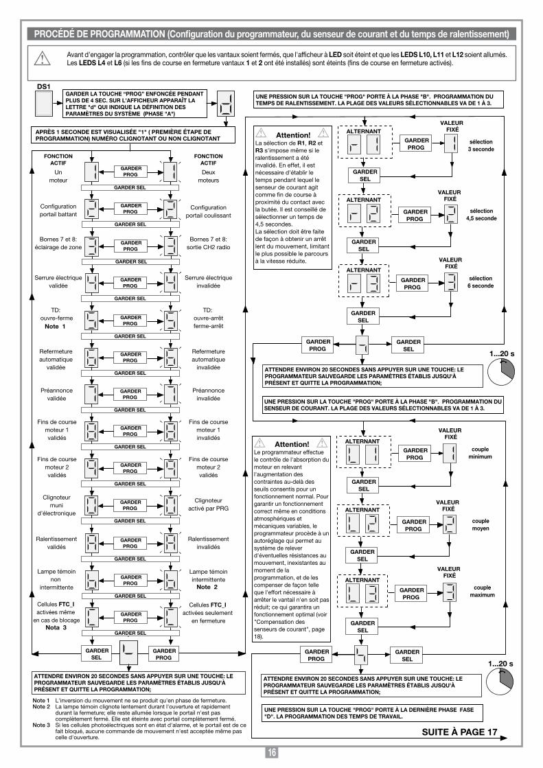
16
Avant d'engager la programmation, contrôler que les vantaux soient fermés, que l'afficheur à LED soit éteint et que les LEDS L10, L11 et L12 soient allumés. Les LEDS L4 et L6 (si les fins de course en fermeture vantaux 1 et 2 ont été installés) sont éteints (fins de course en fermeture activés).
PROCÉDÉ DE PROGRAMMATION (Configuration du programmateur, du senseur de courant et du temps de ralentissement)
GARDER SEL
GARDERPROG
Unmoteur
Configurationportail battant
Configurationportail coulissant
FONCTIONACTIF
Bornes 7 et 8:éclairage de zone
Bornes 7 et 8:sortie CH2 radio
TD: ouvre-ferme
TD: ouvre-arrêtferme-arrêt
Préannoncevalidée
Préannonceinvalidée
Fins de coursemoteur 1validés
Fins de coursemoteur 1invalidés
DS1GARDER LA TOUCHE “PROG” ENFONCÉE PENDANT PLUS DE 4 SEC. SUR L’AFFICHEUR APPARAÎT LA LETTRE "d" QUI INDIQUE LA DÉFINITION DES PARAMÈTRES DU SYSTÈME (PHASE "A")
FONCTIONACTIF
GARDERSEL
1...20 s
ATTENDRE ENVIRON 20 SECONDES SANS APPUYER SUR UNE TOUCHE: LE PROGRAMMATEUR SAUVEGARDE LES PARAMÈTRES ÉTABLIS JUSQU'À PRÉSENT ET QUITTE LA PROGRAMMATION;
APRÈS 1 SECONDE EST VISUALISÉE "1" ( PREMIÈRE ÉTAPE DE PROGRAMMATION) NUMÉRO CLIGNOTANT OU NON CLIGNOTANT
Note 1
Serrure électriquevalidée
Serrure électriqueinvalidée
Refermetureautomatique
validée
Refermetureautomatique
invalidée
UNE PRESSION SUR LA TOUCHE "PROG" PORTE À LA PHASE "B". PROGRAMMATION DU SENSEUR DE COURANT. LA PLAGE DES VALEURS SÉLECTIONNABLES VA DE 1 À 3.
Deuxmoteurs
GARDER SEL
Fins de coursemoteur 2validés
Fins de coursemoteur 2validés
Clignoteurmuni
d’électronique
Clignoteuractivé par PRG
Ralentissementvalidés
Ralentissementinvalidés
Lampe témoinnon
intermittente
Lampe témoinintermittente
Cellules FTC_I activées même
en cas de blocage
Cellules FTC_I activées seulement
en fermeture
GARDERPROG
Note 2
Nota 3
Note 1 L'inversion du mouvement ne se produit qu'en phase de fermeture. Note 2 La lampe témoin clignote lentement durant l'ouverture et rapidement
durant la fermeture; elle reste allumée lorsque le portail n'est pas complètement fermé. Elle est éteinte avec portail complètement fermé.
Note 3 Si les cellules photoélectriques sont en état d'alarme, et le portail est de ce fait bloqué, aucune commande de mouvement n'est acceptée même pas celle d'ouverture.
GARDERPROG
GARDER SEL
GARDERPROG
GARDER SEL
GARDERPROG
GARDER SEL
GARDERPROG
GARDER SEL
GARDERPROG
GARDER SEL
GARDERPROG
GARDER SEL
GARDERPROG
GARDER SEL
GARDERPROG
GARDER SEL
GARDERPROG
GARDER SEL
GARDERPROG
GARDER SEL
GARDERPROG
GARDER SEL
GARDERPROG
GARDERSEL
ALTERNANT
GARDERPROG
GARDERPROG
ALTERNANT
GARDERPROG
VALEUR FIXÉ
GARDERSEL
ALTERNANTVALEUR
FIXÉ
GARDERSEL
VALEUR FIXÉ
sélection3 seconde
sélection4,5 seconde
sélection6 seconde
GARDERPROG
GARDERSEL
Attention! La sélection de R1, R2 et R3 s'impose même si le ralentissement a été invalidé. En effet, il est nécessaire d'établir le temps pendant lequel le senseur de courant agit comme fin de course à proximité du contact avec la butée. Il est conseillé de sélectionner un temps de 4,5 secondes.La sélection doit être faite de façon à obtenir un arrêt lent du mouvement, limitant le plus possible le parcours à la vitesse réduite.
1...20 s
GARDERSEL
ALTERNANT
GARDERPROG
GARDERPROG
ALTERNANT
GARDERPROG
GARDERSEL
ALTERNANT
GARDERSEL
GARDERPROG
GARDERSEL
Attention! Le programmateur effectue le contrôle de l'absorption du moteur en relevant l'augmentation des contraintes au-delà des seuils consentis pour un fonctionnement normal. Pour garantir un fonctionnement correct même en conditions atmosphériques et mécaniques variables, le programmateur procède à un autoréglage qui permet au système de relever d'éventuelles résistances au mouvement, inexistantes au moment de la programmation, et de les compenser de façon telle que l'effort nécessaire à arrêter le vantail n'en soit pas réduit; ce qui garantira un fonctionnement optimal (voir "Compensation des senseurs de courant", page 18).
UNE PRESSION SUR LA TOUCHE "PROG" PORTE À LA PHASE "B". PROGRAMMATION DU TEMPS DE RALENTISSEMENT. LA PLAGE DES VALEURS SÉLECTIONNABLES VA DE 1 À 3.
UNE PRESSION SUR LA TOUCHE "PROG" PORTE À LA DERNIÈRE PHASE FASE "D". LA PROGRAMMATION DES TEMPS DE TRAVAIL.
ATTENDRE ENVIRON 20 SECONDES SANS APPUYER SUR UNE TOUCHE: LE PROGRAMMATEUR SAUVEGARDE LES PARAMÈTRES ÉTABLIS JUSQU'À PRÉSENT ET QUITTE LA PROGRAMMATION;
ATTENDRE ENVIRON 20 SECONDES SANS APPUYER SUR UNE TOUCHE: LE PROGRAMMATEUR SAUVEGARDE LES PARAMÈTRES ÉTABLIS JUSQU'À PRÉSENT ET QUITTE LA PROGRAMMATION;
VALEUR FIXÉ
VALEUR FIXÉ
VALEUR FIXÉ
coupleminimum
couplemoyen
couplemaximum
SUITE À PAGE 17
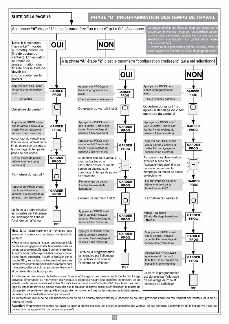
17
Appuyer sur PROG pourlancer la programmation avec:
À la phase “A” étape “1” c’est le paramètre “un moteur” qui a été sélectionné
Ouverture du vantail 1
Fin du temps de pause (déclenchement de la fermeture)
OUI NON
Appuyer sur PROG avantque le vantail 1 arrive à labutée. Fin du réglage du senseur 1 (en ouverture)
Au contact du vantail avecla butée ou à l’activation dufin de course en ouverture,le comptage du temps depause se déclenche.
Fermeture du vantail 1
GARDER PROG
Ouverture du vantail 1 et 2
Fermeture vantaux 1 et 2
GARDER PROG
La fin de la programmation est signalée par l’allumage de l’éclairage de zone etl’éteindre de l'afficheur
GARDER PROG
Ouverture du vantail 1 et, après un décalage de 2 sec. ouverture du vantail 2
GARDER PROG
Appuyer sur PROG avantque le vantail 2 arrive à labutée. Fin du réglage du senseur 2 (en ouverture)
Au contact des deux vantauxavec les butées ou à l’activation des deux fins de course en ouverture, le comptage du temps de pausese déclenche.
GARDER PROG
GARDER PROG
La fin de la programmation est signalée par l’allumage de l’éclairage de zone etl’éteindre de l'afficheur
GARDER PROG
DS1
À la phase “A” étape “2” c’est le paramètre “configuration coulissant” qui a été sélectionné
GARDER PROG
GARDER PROG
GARDER PROG
Appuyer sur PROG avantque le vantail arrive àla butée. Fin du réglage dusenseur 1 (en fermeture)
GARDER PROG
La fin de la programmation est signalée par l’allumage de l’éclairage de zone etl’éteindre de l'afficheur
GARDER PROG
GARDER PROG
GARDER PROG
DS1
GARDER PROG
Appuyer sur PROG avantque le vantail 1 arrive à labutée. Fin du réglage du senseur 1 (en ouverture)
Appuyer sur PROG avantque le vantail 2 arrive à labutée. Fin du réglage du senseur 2 (en fermeture)
Fin du temps de pause (déclenchement de la fermeture)
Appuyer sur PROG avantque le vantail 2 arrive àla butée. Fin du réglage dusenseur 2 (en fermeture)
Appuyer sur PROG avantque le vantail 1 arrive àla butée. Fin du réglage dusenseur 1 (en fermeture)
GARDER PROG
Appuyer sur PROG avantque le vantail 1 arrive à labutée. Fin du réglage du senseur 1 (en ouverture)
Fin du temps de pause et déclenchement de la fermeture vantail 2
Fermeture du vantail 2
GARDER PROG
Vantail 1 se ferme(Fin du décalage fermeture)- Nota 2 -
Appuyer sur PROG avantque le vantail 1 arrive àla butée. Fin du réglage dusenseur 1 (en fermeture)
Appuyer sur PROG avantque le vantail 2 arrive àla butée. Fin du réglage dusenseur 2 (en fermeture)
DS1
Nota 1: la sélection “un vantail” invalide automatiquement les fins de course du vantail 2. L’invalidation, en phase de programmation, des fins de course évite de devoir les court-circuiter sur le bornier.
- Un vantail -
Appuyer sur PROG pourlancer la programmation avec:
- Deux vantaux coulissants -
Au contact des deux vantauxavec les butées ou à l’activation des deux fins de course en ouverture, le comptage du temps de pausese déclenche.
Appuyer sur PROG pourlancer la programmation avec:
- Deux vantaux battants -
OUI NON
SUITE DE LA PAGE 16 PHASE "D" PROGRAMMATION DES TEMPS DE TRAVAIL
La programmation est effectuée étape par étape par le système, embrayant les moteurs en fonction des program-mations faites aux étapes précédentes (par exemple: en sélectionnant la configuration à un vantail, seul le moteur N°1 sera embrayé).Si la serrure et la préannonce ont été validées, celles-ci seront également activées en phase de programmation.
Note 2: Le retard maximum en fermeture pour le vantail 1 correspond au temps de travail du vantail 2. •Pour terminer la programmation des temps une fois qu'elle a été engagée (sans toutefois mémoriser les temps qui se sont écoulés jusqu'à ce moment précis; il s'agit donc de quitter le procédé de programmation d'une façon anormale), il suffit d'appuyer sur la touche SEL; les vantaux se bloquent, et seuls les paramètres inhérents à la définition du système sont mémorisés, sélections du temps de ralentissement et du niveau de couple comprises.
•L'intervention des cellules photoélectriques d'inversion/blocage ou une pression sur la touche de blocage provoque l'interruption du mouvement des vantaux, le clignoteur restant tout de même en fonction; ce qui signale que le programmateur est activé. Sur l'afficheur apparaît alors l'indication "b" clignotante. Le comp-tagedutempsdetravailsebloquemaisdèsquelasituationd'alarmecesseouenrelâchantlatouchedeblocage (active seulement tant qu'elle est appuyée), le mouvement des vantaux reprend automatiquement, de même que l'actualisation du temps de travail.•L'interventiondufindecoursemécaniqueoudufindecourseampèrométrique(senseurdecourant)provoquel'arrêtdumouvementdesvantauxetlafindutemps de travail.Attention! Programmer les temps de travail de façon à obtenir toujours une ouverture complète des vantaux; en cas contraire, l'achèvement de la manœuvre n'est pas garanti (voir paragraphe "Fin de course temporisé").

18
1) AutomatiqueSélectionnable en validant la refermeture automatique (étape 6 de la programmation, numéro "6" non clignotant). En partant de la condition de portail complètement fermé, la commande d'ouverture déclenche un cycle de travail complet qui se terminera par la refermeture automatique et l'extinction temporisée de l'éclairage de zone.La refermeture automatique se déclenche après un retard correspondant au temps d'arrêt programmé, à partir de la conclusion de la manœuvre d'ouverture ou du moment de la dernière intervention des cellules photoélectriques durant le temps d'arrêt (l'intervention des cellules photoélectriques provoque un reset du temps d'arrêt). Durant le temps d'arrêt, sur l'afficheur clignote le symbole . Une pression sur la touche de blocage durant le temps d'arrêt empêche la refermeture automatique et entraîne l'interruption du clignotement sur l'afficheur. L'intervention des fins de course mécaniques ou des fins de course ampèrométriques provoque le blocage du vantail. La lampe témoin reste allumée tant que le portail n'est pas complètement fermé.Nota: l'éclairage de zone s'allume à chaque commande de manœuvre transmise au système, que ce soit par fil ou par radio; l'intervention des cellules photoélectriques durant la phase de fermeture n'a aucun effet sur la temporisation de l'éclairage de zone.
2) Semi-automatiqueSélectionnable en invalidant la refermeture automatique (étape 6 de la programmation, numéro "6" clignotant). Le cycle de travail est géré par des commandes distinctes d'ouverture et de fermeture. Une fois que le système est arrivé en position d'ouverture complète, une commande de fermeture, par radio ou au moyen de la touche, s'impose pour compléter le cycle. L'intervention du fin de course d'ouverture provoque le blocage du vantail et la fin de la manœuvre d'ouverture. À la fin de la manœuvre d'ouverture, l'éclairage de zone s'éteint dès écoulement du temps préétabli. La lampe témoin reste allumée tant que le portail n'est pas complètement fermé.
OUVERTURE PARTIELLEElle s'effectue sur le vantail 1; en cas de configuration du système à deux vantaux, on obtiendra l'ouverture complète du vantail 1; en cas de configuration du système à un vantail, on obtiendra l'ouverture partielle du vantail 1 (environ 1/3 de la course). La commande ne peut être exécutée que si les vantaux sont complètement fermés. Si durant l’ouverture partielle, on active de nouveau la commande "TAL", le vantail 1 se bloque; la commande suivante déclenchera sa fermeture. À ce point, pour que la commande puisse de nouveau être exécutée, il faudra que les vantaux soient com-plètement fermés.
ÉCLAIRAGE DE ZONE / SORTIE CH2 RADIOLes bornes "7" et "8" correspondent aux contacts C-NO d'un relais; celui-ci pourra être activé comme d'habitude, c'est-à-dire selon le procédé "éclairage de zone" (contact fermé pendant le temps programmé) ou directement par le deuxième canal radio, sélectionnable sur le décodeur intégré à la centrale (cavalier "J1". Les bornes "7" et "8" produisent seulement un contact non alimenté et ne fournissent pas de tension à l'extérieur; ceci signifie que pour utiliser l'éclairage de zone, il faudra alimenter le circuit séparément et utiliser le contact comme un simple interrupteur.
Attention! Sur la carte du programmateur il n'y a pas de tension à 230 Vac mais seulement de la basse tension. Pour la conformité à la norme de sécurité électrique qui impose certaines isolations entre les pistes à haute tension (230 Vac) et celles à basse tension (24 Vac), il ne faudra pas brancher les bornes "7" et "8" directement sur un circuit avec tension 230 Vac. La tension maximale permise est 30Vac/dc
MODE MANUELIl trouve son utilité pour fermer ou ouvrir les vantaux sous le contrôle direct de l'opérateur. Dans ce mode de fonctionnement, les dispositifs de sécurité FTC_I, FTC_S et TB agissent seulement tant qu'ils sont en état d'alarme. L'objectif est de faciliter l'installation et d'avoir les vantaux complètement fermés avant de procéder à la programmation du système. Dans ce mode de fonctionnement, le LED "L3" (marqué de "UPL") reste allumé. Le mode de fonctionnement manuel peut être activé même lors du fonctionnement à batterie; les moteurs sont alors alimentés à la tension maximale (vitesse de régime), que le ralentissement ait été validé ou non. Les dispositifs de sécurité FTC_I (uniquement en fermeture, quelle que soit la sélection à l'étape "C" de la définition des paramètres du système) et FTC_S sont gérés, de même que les fins de course et les senseurs de courant.
• Manœuvre de fermetureRéalisable en gardant le bouton "SEL" enfoncé. La manœuvre de fermeture se bloque par:- relâchementdubouton"SEL" (on quitte le mode manuel);- activation de la touche de blocage "TB"; pour relancer la manœuvre de fermeture, il est
nécessairederelâcherlebouton"SEL" et de le réappuyer;- activation du fin de course en fermeture: une pression sur le bouton "SEL" n'entraîne
pas la fermeture mais simplement l'allumage de l'éclairage de zone.
•Manœuvred'ouvertureRéalisable en gardant le bouton "SEL" enfoncé et en appuyant tout de suite après sur le bouton "PROG".La manœuvre d'ouverture se bloque par:- relâchementdesdeuxboutons(onquittelemodemanuel);- activation de la touche de blocage "TB"; pour relancer la manœuvre d'ouverture, il est
nécessairederelâcherlesdeuxboutonsetdelesréappuyer;- activation du fin de course en ouverture.
• Inversion du mouvementDurant la phase de fermeture: pour passer à la manœuvre d'ouverture, appuyer sur le bouton "PROG".Durantlaphased'ouverture:pourpasseràlamanœuvredefermeture,relâcherlebouton"PROG".
•ÉclairagedezoneL'éclairage de zone est allumé pendant que le" mode manuel" est activé. Il s'allume également pendant qu'on essaie de délivrer une commande mais le fin de course en empêche l'exécution.
COMPENSATION DES SENSEURS DE COURANTLe relèvement du courant absorbé par les moteurs est effectué de façon à pouvoir compenser les éventuelles petites variations dues aux conditions de l'environnement. Le cas échéant, il y aura sur l'afficheur une indication supplémentaire qui consiste en un trait clignotant (plus grande est la compensation en cours et plus rapide sera le clignotement). Ce trait se trouvera du côté gauche de l'afficheur pour le senseur 1 et du côté droit pour le senseur 2 (voir "Indications de l'afficheur" page 29-30). À chaque blocage du mouvement, manœuvre d'inversion comprise, la compensation est mise à zéro et recalculée ensuite pour une actualisation continue.
SIGNALISATIONS D'ALARME1) Paramètres erronés mémorisés sur EEPROMSur l'afficheur clignote la lettre , le système s'est bloqué. L'unique possibilité est celle d'accéder de nouveau à la modalité de programmation pour reprogrammer le système. Si en répétant l'opération, cet inconvénient se manifeste encore, il y a un problème sur EEPROM (il n'est pas possible de mémoriser correctement). Mettre le système hors tension et essayer après quelques instants de le rallumer et de le reprogrammer.
2) Fins de course ouverture/fermeture activés simultanémentSur l'afficheur apparaît la lettre , le système s'est bloqué. Le clignoteur s'active pendant environ 3 secondes avec un intervalle de six secondes et continue à cligno-ter. Mettre le système hors tension, vérifier l'état des fins de course et le remettre sous tension.
FIN DE COURSE TEMPORISÉLa gestion des temps de travail permet de contrôler la position des vantaux. En cas de coupure de courant, le programmateur, à moins qu'un des deux fins de course ne s'avère activé, perd la mémorisation de la position occupée par les vantaux; ces derniers sont alors considérés comme étant "complètement fermés", de façon à permettre la manœuvre d'ouverture. La gestion des temps de travail garantit successivement une manœuvre de fermeture complète. Plusieurs manœuvres d'inversion effectuées l'une après l'autre, entraînant donc l'arrêt du mouvement et un démarrage lent, pourraient avoir comme conséquence une altération du contrôle des temps et un manque de ralentissement avant l'arrivée au fin de course. Le système fonctionnera de nouveau correctement à la manœuvre successive.
Il est possible de commander à distance le moteur par le biais d’une télécommande; on dispose de la fonction de commande séquentielle "ouverture-arrêt-fermeture-arrêt" ou "ouverture-fermeture" (sélectionnable); ce qui est faisable avec n’importe quel canal à disposition. Si lors de la configuration des paramètres du système, le nombre "3" clignotant a été sélectionné, on dispose d’un deuxième canal avec contact en sortie C-NO (bornes 7-8).
Module de mémoireExtractible et doté de mémoire non volatile de type EEPROM, il contient les codes des émetteurs et permet la mémorisation de 300 codes (300 touches de canal). Dans ce module, les codes restent mémorisés même en cas de coupure de courant.
Avant de procéder à la première mémorisation, se rappeler d'effacer entièrement la mémoire.
Attention! S'il faut remplacer la carte électronique à cause d'un défaut de fonctionnement, il est possible d'insérer le module de mémoire dans une nouvelle carte. Son insertion devra se faire obligatoirement dans le sens indiqué en fig. 1 dét. A.
GESTION DES CODES DES ÉMETTEURSSignalisations LED "L2" (fig.1): clignotement rapide: effacement d'un codeclignotement lent: mémorisation d'un codetoujours allumé: mémoire saturée
Mémorisation d'un canal (fig.1):1. Appuyer sur le bouton "P3" MEMO et le garder enfoncé; le LED "L2" se met à
clignoter lentement.2. Activer simultanément l'émetteur sur le canal à mémoriser.3. Garder le bouton "P3" MEMO enfoncé jusqu'au moment où le LED "L2" se remet
à clignoter.
MODE DE FONCTIONNEMENT
COMMANDE PAR RADIO S449

19
4.Relâcherlebouton"MEMO";leLED continue à clignoter.5. Activer une deuxième fois l'émetteur (même émetteur, même canal; si le canal est
différent ou s'il s'agit d'un autre émetteur, la mémorisation échoue).6. Fin de la mémorisation; le LED "L2" reste allumé pendant 2 secondes, signalant
ainsi la réussite de la mémorisation.
Note: il n'est pas possible de mémoriser un code déjà mis en mémoire. Si ce cas se présente, le clignotement du LED s'interrompt durant l'activation de la télécommande radio (2ème point). Ce n'est qu'après relâchement du bouton "P3" MEMO qu'il sera possible de reprendre la mémorisation. Si dans les 15 secondes qui suivent la première activation de la télécommande radio, on ne l'active pas une deuxième fois, on quitte automatiquement le procédé de mémorisation sans que le nouveau code usager ait été mémorisé.
Effacement d'un canal (fig.1):1. Appuyer sur le bouton "P4" DEL et le garder enfoncé; le LED "L2" se met à
clignoter rapidement.2. Activer l'émetteur sur le canal à effacer.3. Le LED reste allumé pendant 2 secondes, signalant ainsi que l'effacement a eu
lieu.
Note: si l'usager que l'on désire effacer n'est pas mémorisé, le LED s'arrête de clignoter; ilserapossibledereprendrel'effacementseulementaprèsrelâchementdubouton"P4".Enrelâchantleboutonavantl'activationdelatélécommanderadio,onquitteimmédiatement le procédé, qu'il soit de mémorisation ou d'effacement.
Effacement total de la mémoire usagers (fig.1):1. Appuyer simultanément sur les deux boutons ("P3 + P4") et les garder enfoncés
pour plus de 4 secondes.2. Le LED "L2" reste allumé pendant toute la durée de l'effacement (environ 8
secondes).3. L'extinction du LED "L2" signale la conclusion de l'effacement.
Note: lorsque la mémoire du récepteur est presque saturée, la recherche de l'usager peut durer 1 seconde à compter de la réception de la commande radio. Si le LED "L2" reste toujours allumé, la mémoire est saturée. Pour pouvoir mémoriser un nouveau TX, l'annulation d'un code de la mémoire s'impose.
Mémorisation par radio d'autres canaux • La mémorisation peut être activée également par radio (sans devoir ouvrir
le boîtier contenant la centrale), si le cavalier "J2" (fig. 1) a été inséré.
1) Vérifier si le cavalier "J2" a été inséré (fig. 1).
2) Utiliser une télécommande dont au moins une des touches de canal "A-B-C-D" a déjà été mémorisée dans le récepteur et activer la touche à l'intérieur de la télécommande comme indiqué en figure.
Nota: tous les récepteurs qui se trouvent dans le rayon d'action de la télécom-mande et qui ont au moins un canal de l'émetteur de mémorisé, enclencheront simultanément l'avertisseur sonore "B1" (fig. 1).
3) Pour sélectionner le récepteur dans lequel il faut mémoriser le nouveau code, activer une des touches de canal de ce même émetteur. Les récepteurs qui ne contiennent pas le code de cette touche se désactiveront; ce qui est signalé par un bip de 5 secondes. Par contre, le récepteur contenant le code émettra un bip différent qui dure 1 seconde, signalant l'accès effectif au procédé de mémorisation "par radio".
4) Appuyer sur la touche de canal choisie précédemment sur l'émetteur à mémoriser. Le récepteur signalera que la mémorisation a eu lieu en émettant 2 bips d'une demi-seconde. Après quoi, le récepteur sera prêt à mémoriser un autre code.
5. Pour quitter le procédé de mémorisation, laisser passer 5 secondes sans mémoriser de codes. Le récepteur émettra un bip de 5 secondes et sortira du procédé.
• Lorsquelamémoirearriveàsaturation,l'avertisseursonoreémettra10bipstrèscourts et on sort automatiquement du procédé de mémorisation "par radio"; le LED "L2" reste allumé. Cette signalisation s'obtient également à chaque tentative d'accéder au procédé de mémorisation "par radio" avec mémoire saturée.
BRANCHEMENT DE L'ANTENNE POUR MODULE RF 433 MHzLe récepteur est équipé d'une propre antenne qui consiste en un morceau de fil rigide d'une longueur de 170 mm. En alternative, il est possible de brancher l'antenne accordée ANS400 aumoyend'uncâblecoaxialRG58 (impédance 50Ω) d'une longueur maxi. de 15 m.
En cas de coupure de courant, le programmateur, s'il est muni du groupe batteries PRG850BC, peut continuer à fonctionner. Observer ce qui suit:
• Lefonctionnementàbatterie,lorsqueleportailestcomplètementfermé,estsignalépar un trait qui court le long du "périmètre externe" (voir page 15). Pour signaler que les batteries se sont déchargées jusqu'au niveau de garde, il court dans la moitié inférieure de l'afficheur. Dans une telle situation, la lampe témoin s'activera environ toutes les 30 secondes, effectuant ainsi 4 clignotements. Lorsque la batterie se décharge trop, la lettre "C" est visualisée, et le programmateur se bloque complètement (uniquement avec portail complètement fermé).
Une fois que la tension du réseau a été rétablie et la tension de la batterie augmente, le système se débloque automatiquement et l'indication sur l'afficheur change.
• Quandleportailestcomplètementfermé,leschargesexternes(cellulesphotoé-lectriques, détecteurs de masses métalliques) ne sont pas alimentées, ceci pour augmenter l'autonomie des batteries. Lorsqu'on active une commande (par fil ou par radio), le programmateur, en premier lieu, alimente les charges et évalue l'état des dispositifs de sécurité. Il s'ensuit que l'exécution de la commande, si elle est autorisée (dispositifs de sécurité à l'état de veille), sera retardée pour le temps nécessaire à la reprise du fonctionnement correct des dispositifs de sécurité (environ 1 seconde). Après ce laps de temps, le relevé d'une alarme au niveau d'un dispositif de sécurité provoquera d'une part l'inexécution de la commande et d'autre part la coupure automatique de l'alimentation aux charges externes. Le programmateur revient alors à l'état de veille.
Attention! Pour les raisons indiquées ci-dessus, si l'on désire utiliser un récepteur externe, il faudra toujours l'alimenter en appliquant la tension de la batterie; ce n'est que de cette façon que la commande par radio pourra actionner le portail.
• Silatensionduréseaufaitdéfautpendantlamanœuvredesvantaux,ceux-cisebloqueront pendant environ une seconde pour que la tension de la batterie puisse alimenter correctement les dispositifs de sécurité. Après quoi, la manœuvre reprendra dans le même sens.• Mêmelorsdufonctionnementàbatterieilestpossibled'accéderàlaprogrammationpour modifier les paramètres du système, la sélection du ralentissement et celle du couple. Par contre, il n'est pas possible de programmer les temps de travail. Donc, dès visualisation du symbole "d'attente" (après L3), en appuyant sur la touche PROG on quittera automatiquement le procédé de programmation.
REMPLACEMENT DES BATTERIES
Les batteries ne doivent être remplacées que par des techniciens agréés. Les batteries usées doivent être détruites conformément aux normes en vigueur. Lorsque le programmateur arrive au terme de sa vie, avant de le confier à qui se chargera de sa destruction, enlever les batteries et les éliminer séparément.
CHARGEUR DE BATTERIE (EN OPTION)

20
WICHTIGE HINWEISE WICHTIGE HINWEISE WICHTIGE HINWEISE
herabgesetzt (sofern eine Verlangsamung während der Programmierung nicht ausgeschlossen wurde). Die Programmierung, die mit Hilfe von nur zwei Tasten durchführbar ist, ermöglicht die Konfiguration des Systems, der Dauer der Verlangsamungsphase, der Beanspruchungssensoren und der Arbeits-/Pausen-zeiten. Das Auslösen des Sicherheitssensors (Antiquetschvorrichtung) während der Schließphase bewirkt eine Bewegungsumkehr, und dasselbe erfolgt in der Öffnungsphase (falls die automatische Wiederverschließung eingestellt wurde; andernfalls wird die Blockierung verursacht). Wenn die Bewegung jedoch schon in der Endphase ist, wirkt der Sensor als Endanschlag.
Beschreibung der elektronische PlatineB1 Signalisierung-Summer Betriebsweise "durch Funk"DS1 7-stelliges LED-DisplayF1 Flink Schmelzsicherung 1A - Schutz gegen Überlastungen der 24V-LeitungF2 Träge Schmelzsicherung 3,15A - Schutz gegen Überlastungen der Elektro-
schloss-Stromversorgung (nur bei Batteriebetrieb)F3 Flink Schmelzsicherung 10A - Schutz gegen Überlastungen der Motoren-
stromversorgungF4 Flink Schmelzsicherung 10A - Schutz gegen Überlastungen der Motoren-
stromversorgungJ1 KanalwahlJ2 Befähigung zur Speicherung über Funk (ohne das Gehäuse zu öffnen)L1 LED Platine versorgtL2 LED Verwaltung Sender-CodesL3 LED Manueller BetriebL4 LED Signalisierung Endanschlag Schließung Torflügel 1 (FCC1)L5 LED Signalisierung Endanschlag Öffnung Torflügel 1 (FCA1)L6 LED Signalisierung Endanschlag Schließung Torflügel 2 (FCC2)L7 LED Signalisierung Endanschlag Öffnung Torflügel 2 (FCA2)L8 LED Signalisierung TAL9 LED Signalisierung TCL10 LED Signalisierung TBL11 LED Signalisierung FTC_IL12 LED Signalisierung FTC_SM1 Speichermodul (oder 300 Codes)P1 ProgrammiertasteP2 WahltasteP3 Speichertaste des Sender-CodesP4 Löschtaste Sender-CodesR1 Modul RF zu 433,92 MHzV0-V1 Anschluss an Sekundärstrom 1 des Transformators (0-24 Vac) Grau-GrauVB Anschluss an Batteriespannung 12 Vdc (nur zum Betrieb des Elektroschloßes
bei Batteriestromversorgung)V2-V3 Anschluss an Sekundärstrom 2 des Transformators (0-15 Vac) Braun-Braun V4-V5 Anschluss an Sekundärstrom 3 des Transformators (0-20 Vac) Rot-Rot
Achtung! Nur für EG-Kunden – WEEE-Kennzeichnung.Das Symbol zeigt an, dass das Produkt am Ende seines Lebens-zyklus getrennt von anderen Abfällen gesammelt werden muss. Der Benutzer muss daher das Gerät in geeignete Zentren für die getrennte Sammlung von Elektronik- und Elektroschrott bringen oder zum Zeitpunkt des Erwerbs eines neuen Geräts gleicher Art im Verhältnis eins zu eins beim Händler abgeben.
Die geeignete getrennte Sammlung für die Zuführung zum Recycling, zur Aufbereitung und zur umweltfreundlichen Entsorgung trägt dazu bei, mögliche negative Auswirkungen auf die Umwelt und die Gesundheit zu vermeiden und fördert das Recycling der Materialien. Die widerrechtliche Entsorgung des Produkts durch den Besitzer führt zur Anwendung der von den geltenden Vorschriften im Mitgliedstaat der Europäischen Gemeinschaft vorgesehenen Verwaltungsstrafen.
•Bevor mit der Installation begonnen wird, sollte das vorliegende Heft aufmerksam gelesen werden. Insbesondere sollten die vom Produkt vorgesehen Sicher-heitseinrichtungen zwecks bester Effizienz in Augenschein genommen werden.
• Im vorliegenden Heft werden nicht alle von den rechtskräftigen Normeneventuell vorgeschriebenen Sicherheitseinrichtungen in Betracht gezogen. Der Installateur muss persönlich dafür sorgen, dass die fehlenden Einrich-tungen hinzugefügt werden und sie den im vorliegenden Heft beschriebenen Produkten vorgeschaltet oder nachgeschaltet installieren.
•DieVerwendungderProdukteundihreZweckbestimmungzueinemande-ren Gebrauch, als es vorgesehen und/oder geraten wurde, ist nicht vom Hersteller erprobt worden. Die Installationsarbeiten erfolgen daher unter der vollständigen Verantwortung des Installateurs.
•DasvorliegendeHandbuchwendetsichanPersonen,diezur Installationvon "Elektrogeräten" befähigt sind und setzt eine gute berufliche Kenntnis der Technik voraus. Der Hersteller lehnt jede Verantwortung für eventuelle Schäden ab, die durch die fehlende Beachtung der zur Zeit geltenden Sicher-heitsnormen bei der Installation entstanden sind.
Achtung! Der Programmierer darf ausschließlich mit unseren Motoren der Produktreihe "BL", "HL" und "GL" verwendet werden.
Programmierer für zwei Gleichstrommotoren mit eingebautem Empfänger, der je nach gewähltem Modell die Speicherung von oder 300 Benutzercodes ermöglicht (siehe "Fernbedienung", Seite 46). Die Decodierung ist vom Typ "Rolling Code" und die Betriebsfrequenz beträgt 433,92 MHz.Die Drehgeschwindigkeit des Motors wird elektronisch gesteuert. Langsame Start-geschwindigkeit mit dann zunehmender Steigerung; für ein kontrolliertes Anhalten der Bewegung wird bereits vor Erreichen des Endanschlags die Geschwindigkeit
VOR DER INSTALLATION SOLLTEN DIE NACHSTEHENDEN HINWEISE AUFMERKSAM GELESEN UND FÜR SPÄTERE VERWENDUNG AUFBEWAHRT WERDEN. BESONDERE AUFMERKSAMKEIT SOLLTE ALLEN IM TExT BEFINDLICHEN HINWEISEN GESCHENKT WERDEN. DEREN NICHT-BEACHTUNG KÖNNTE DEN ORDENTLICHEN BETRIEB DES SYSTEMS BEEINTRÄCHTIGEN.
ELEKTRONISCHER PROGRAMMIERER
Co
llegam
enti scheda b
ase
PR
G852
19-12-2008
DC
0445D
escription :
Prod
uct Cod
e :
Date:
Draw
ing numb
er :
P.J.Heath
CA
RD
IN E
LE
TT
RO
NIC
A S
.p.A
- 31020 San Vend
emiano
(TV
) Italy - via Raffaello
, 36 Tel: 0438/401818 Fax: 0438/401831
Draft :
All rights reserved
. Unauthorised
copying or use of the inform
ation contained in this d
ocument is p
unishable b
y law
PR
G852
F2 T3.15A
CS1046B DC0344
F1 F1A
2930
P4P3
DELMEMO
L2
DS1
V5
V4
V3
V2
ELS
12V
1098765 161514131211 222120191817 282726252423
LC- O
UT C
H2
LS 24V
CM
N
LP 24V
OU
T 24V
CM
N
FCC
1
FCA
1
FCC
2
FCA
2
TAL
TA TC TD CM
N
CM
N
TB FTC_I
FTC_S
CM
N
F4 F10A
F3 F10A
P2P1
SELPROG L3
L4 L5 L6 L7 L8 L9 L10 L11 L12
L1
VB
V1V0
CHA
CHB
CHC
CHD
CH 1Comando dinamicoDynamic command
Commande dynamiqueDynamische Steuerung
Mando dinámico
Selezione canaliChannel selectionSélection canalKanalwahlSelección
CH 2Comando ausiliarioAuxiliary command
Commande auxiliareHilfssteuerungMando auxiliar
CHA
CHBCHC
CHD
J1
CH
A
CH
B
CH
C
CH
D
M1 M2
2 31 4
R1M1
S449
24C16A)
J2 J2
B1
SPR
1

21
Vor der Ausführung des Elektroanschlusses sicherstellen, dass die auf dem Typenschild angegebene Spannung und Frequenz mit denen der elektrischen Stromversorgung übereinstimmen. Zwischen der Steuereinheit und dem Stromnetz muss ein allpoliger Schalter mit einem Öffnungsabstand zwischen den Kontakten von mindestens 3 mm zwischengeschaltet werden.
• DieDrähtederSteuereinheitundderSicherheitsvorrichtungenanschließen.• DasStromversorgungskabelmittelsderlosenAnschlussklemmleisteandieVorrichtung
(die schon an den Primärstrom des Transformators angeschlossen ist, schwarz-weiße Drähte) anschließen.
• KeinKabelmitAluminiumleiter;dieindieAnschlussklemmleisteeinzuführendenKabelen-den nicht verzinnen; Kabel mit der Markierung "T min 85°C, wetterbeständig" verwenden.
• Die Leitermüssen angemessen in derNähederAnschlussklemmleiste so befestigtwerden, dass sowohl die Isolierung als auch der Leiter festsitzen (ein Kabelband ist ausreichend).
Anschlüsse auf der Klemmleiste 1-2 Ausgang Motor 1: zum Öffnen: Pluspol an Anschlussklemme 1 und Minuspol an Klemme 2 zum Schließen: Minuspol an Anschlussklemme 1 und Pluspol an Klemme 23-4 Ausgang Motor 2: zum Öffnen: Pluspol an Anschlussklemme 3 und Minuspol an Klemme 4 zum Schließen: Minuspol an Anschlussklemme 3 und Pluspol an Klemme 45 Gemeinsame Anschlüsse für alle Eingänge und Ausgänge6 Ausgang Elektroschloss (Gleichstrombetrieb) 12 Vdc -15 W; sie sollte vom
Schwingtyp sein (sich also nicht automatisch rückladen), da die Betätigung eine Sekunde dauert.
7-8 Ausgang (Spannungsfreier normalerweise geöffneter Kontakt) zur Betätigung des Wachlichtes (separate Stromversorgung Vmax= 30 Vac/dc: Imax=1A) oder für den zweiten Funkkanal. Die Wahl wird während der Programmierung getroffen.
9 Ausgang Kontrolleuchte 24 Vac 3 W 10 Ausgang Blinklicht 24 Vac 10 W (kontinuierliche/intermittierende Aktivierung)11 Ausgang für externe Stromverbraucher 24 Vac 10 W 12-13 Gemeinsame Anschlüsse für alle Eingänge und Ausgänge14 FCC1 (N.C.-Kontakt) Eingang Endanschlag für Schließung Torflügel 115 FCA1 (N.C.-Kontakt) Eingang Endanschlag für Öffnung Torflügel 116 FCC2 (N.C.-Kontakt) Eingang Endanschlag für Schließung Torflügel 217 FCA2 (N.C.-Kontakt) Eingang Endanschlag für Öffnung Torflügel 218 TAL (N.O.-Kontakt) Eingang Taste für eingeschränkte Öffnung 19 TA (N.O.-Kontakt) Eingang Öffnungstaste20 TC (N.O.-Kontakt) Eingang Schließtaste21 TD (N.O.-Kontakt) Eingang zur sequentiellen Steuerung (öffnen-blockieren-schließen-
blockieren) oder öffnen-schließen mit Bewegungsrichtungsumkehrung nur bei der Schließung gemäß den Programmeinstellungen.
22-23 Gemeinsame Anschlüsse für alle Eingänge und Ausgänge24 TB (N.C.-Kontakt) Eingang Blockiertaste25 FTC_I (N.C.-Kontakt) Eingang für Sicherheitsvorrichtungen (Bewegungsumkeh-
runglichtschranken). Die Öffnung des Kontakts anschließend an die Intervention der Sicherheitsvorrichtungen, während der Schließphase, aktiviert die Laufrich-tungsumkehr.
26 FTC_S (N.C.-Kontakt) Eingang für Sicherheitsvorrichtungen (Lichtschranke für Stop). Bei der Rückführung in Ruhestellung nach der Pause beginnt die Schließbewegung (nur bei Automatikbetrieb)
27-28 Gemeinsame Anschlüsse für alle Eingänge und Ausgänge29 Innenleiter Funkempfängerantenne (17cm langen starren Draht oder eine externe
ANS400 Antenne mittel Koaxialkabel RG58 Impedanz 50Ω anschließen)30 Aussenleiter Funkempfängerantenne
ALLE NICHT VERWENDETEN N.C.-KONTAKTE MÜSSEN ÜBERBRÜCKT WERDEN(für die bei der Programmierung außer Betrieb gesetzten Endanschläge nicht notwendig)Den Stromkreis einschalten und überprüfen, ob der Zustand der roten Signalisierungs-LEDs wie folgt ist:
- L1 LED Versorgung des Kreislaufs eingeschaltet- L4 LED Endanschlag der Schließung Torflügel 1 "FCC1" eingeschaltet*- L5 LED Endschalter der Öffnung Torflügel 1 "FCA1" eingeschaltet*- L6 LED Endanschlag der Schließung Torflügel 2 "FCC2" eingeschaltet*- L7 LED Endschalter der Öffnung Torflügel 2 "FCA2" eingeschaltet*- L8 Signalisierungs-LED Öffnungstaste "TA" ausgeschaltet- L9 Signalisierungs-LED Schließtaste "TC" ausgeschaltet- L10 Sicherheits-LED Blockiertaste "TB" eingeschaltet*- L11 LED Bewegungsumkehrunglichtschranken "FTC_I" eingeschaltet*- L12 Signalisierungs-LED Lichtschranke für Stop "FTC_S" eingeschaltet*
* Die Leuchtdioden leuchten, wenn die entsprechende Sicherheitsvorrichtung nicht aktiviert ist (hängt von der Position des Torflügels ab und ob Endschalter vorhanden). Sicherstellen, dass bei Aktivierung der Sicherheitsvorrichtungen die entsprechenden LEDs ausgeschaltet werden. Falls sich die LED der Versorgung L1 nicht einschaltet, den Zustand der Schmelzsicherung "F1" und die Kabelverbindung der 230V-Wechselstromversorgung überprüfen. Falls sich eine oder mehrere der Sicherheits-LEDs nicht einschalten, die Kon-takte der jeweiligen angeschlossenen Sicherheitsvorrichtung überprüfen bzw. kontrollieren, dass die Kontakte der nicht verwendeten Sicherheitsvorrichtungen auf der Klemmenleiste überbrückt sind.
Alarm für beide mechanischen gleichzeitig aktivierten Endanschlagsschalter
Fehler bei den gespeicherten Paramtern
Blockierung in der Programmierungsmodalität der Zeiten (aufgrund von: TB, FTC_I, FTC_S)
Definition der Systemkonfiguration
Wartephase nach der Programmierung der Parameter
Wartephase nach der Programmierung der Verlangsamung
Wartephase nach der Programmierung des Niveaus der Stromsensoren
Verlangsamungszeit (Wert 1)
Niveau 1 für den Stromsensor
Programmierung der Betriebszeiten
Öffnungsphase
Blockierung
Pause bei der Wiederverschließung (nur falls befähigt)
Schließphase
Neueinstellung des Stromsensors des Torflügels 1 (bei der Programmierung)
Neueinstellung des Stromsensors des Torflügels 2 (bei der Programmierung)
Neueinstellung beider Stromsensoren Torflügel 1, 2 (bei der Programmierung)
Öffnung + Kompensation Stromsensor 1
Öffnung + Kompensation Stromsensor 2
Schließung + Kompensation Stromsensor 1
Schließung + Kompensation Stromsensor 2
Batteriebetrieb mit geladener Batterie
Batteriebetrieb mit entladener Batterie
Blockierung aufgrund entladener Batterie
ELEKTROANSCHLUSS ANZEIGEN AUF DEM DISPLAY
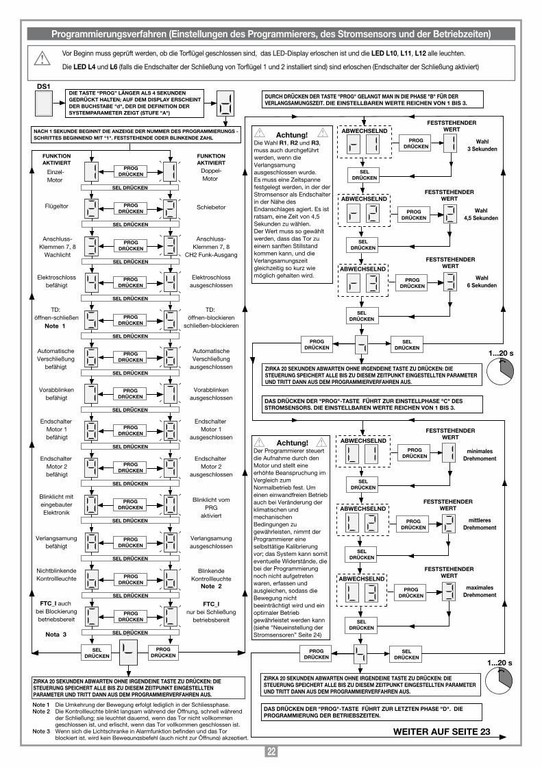
22
Vor Beginn muss geprüft werden, ob die Torflügel geschlossen sind, das LED-Display erloschen ist und die LED L10, L11, L12 alle leuchten.
Die LED L4 und L6 (falls die Endschalter der Schließung von Torflügel 1 und 2 installiert sind) sind erloschen (Endschalter der Schließung aktiviert)
Programmierungsverfahren (Einstellungen des Programmierers, des Stromsensors und der Betriebzeiten)
SEL DRÜCKEN
PROGDRÜCKEN
Einzel-Motor
Flügeltor Schiebetor
FUNKTIONAKTIVIERT
Anschluss-Klemmen 7, 8
Wachlicht
Anschluss-Klemmen 7, 8
CH2 Funk-Ausgang
TD: öffnen-schließen
TD: öffnen-blockieren
schließen-blockieren
Vorabblinkenbefähigt
Vorabblinkenausgeschlossen
Endschalter Motor 1befähigt
Endschalter Motor 1
ausgeschlossen
DS1DIE TASTE “PROG” LÄNGER ALS 4 SEKUNDENGEDRÜCKT HALTEN; AUF DEM DISPLAY ERSCHEINTDER BUCHSTABE "d", DER DIE DEFINITION DERSYSTEMPARAMETER ZEIGT (STUFE "A")
FUNKTIONAKTIVIERT
SELDRÜCKEN
1...20 s
ZIRKA 20 SEKUNDEN ABWARTEN OHNE IRGENDEINE TASTE ZU DRÜCKEN: DIE STEUERUNG SPEICHERT ALLE BIS ZU DIESEM ZEITPUNKT EINGESTELLTEN PARAMETER UND TRITT DANN AUS DEM PROGRAMMIERVERFAHREN AUS.
NACH 1 SEKUNDE BEGINNT DIE ANZEIGE DER NUMMER DES PROGRAMMIERUNGS - SCHRITTES BEGINNEND MIT "1". FESTSTEHENDE ODER BLINKENDE ZAHL
Note 1
Elektroschlossbefähigt
Elektroschlossausgeschlossen
AutomatischeVerschließung
befähigt
AutomatischeVerschließung
ausgeschlossen
DAS DRÜCKEN DER "PROG"-TASTE FÜHRT ZUR EINSTELLPHASE "C" DES STROMSENSORS. DIE EINSTELLBAREN WERTE REICHEN VON 1 BIS 3.
Doppel- Motor
SEL DRÜCKEN
Endschalter Motor 2befähigt
Endschalter Motor 2
ausgeschlossen
Blinklicht miteingebauterElektronik
Blinklicht vomPRG
aktiviert
Verlangsamungbefähigt
Verlangsamungausgeschlossen
NichtblinkendeKontrollleuchte
BlinkendeKontrollleuchte
FTC_I auch bei Blockierungbetriebsbereit
FTC_Inur bei Schließung
betriebsbereit
PROGDRÜCKEN
Note 2
Nota 3
Note 1 Die Umkehrung der Bewegung erfolgt lediglich in der Schliessphase. Note 2 Die Kontrollleuchte blinkt langsam während der Öffnung, schnell während
der Schließung; sie leuchtet dauernd, wenn das Tor nicht vollkommen geschlossen ist, und erlischt, wenn das Tor vollkommen geschlossen ist.
Note 3 Wenn sich die Lichtschranke in Alarmfunktion befinden und das Tor blockiert ist, wird kein Bewegungsbefehl (auch nicht zur Öffnung) akzeptiert.
PROGDRÜCKEN
SEL DRÜCKEN
PROGDRÜCKEN
SEL DRÜCKEN
PROGDRÜCKEN
SEL DRÜCKEN
PROGDRÜCKEN
SEL DRÜCKEN
PROGDRÜCKEN
SEL DRÜCKEN
PROGDRÜCKEN
SEL DRÜCKEN
PROGDRÜCKEN
SEL DRÜCKEN
PROGDRÜCKEN
SEL DRÜCKEN
PROGDRÜCKEN
SEL DRÜCKEN
PROGDRÜCKEN
SEL DRÜCKEN
PROGDRÜCKEN
SEL DRÜCKEN
PROGDRÜCKEN
SELDRÜCKEN
PROGDRÜCKEN
PROGDRÜCKEN
PROGDRÜCKEN
FESTSTEHENDERWERT
SELDRÜCKEN
FESTSTEHENDERWERT
SELDRÜCKEN
FESTSTEHENDERWERT
Wahl3 Sekunden
Wahl4,5 Sekunden
Wahl6 Sekunden
PROGDRÜCKEN
SELDRÜCKEN
ZIRKA 20 SEKUNDEN ABWARTEN OHNE IRGENDEINE TASTE ZU DRÜCKEN: DIE STEUERUNG SPEICHERT ALLE BIS ZU DIESEM ZEITPUNKT EINGESTELLTEN PARAMETER UND TRITT DANN AUS DEM PROGRAMMIERVERFAHREN AUS.
Achtung! Die Wahl R1, R2 und R3, muss auch durchgeführt werden, wenn die Verlangsamung ausgeschlossen wurde. Es muss eine Zeitspanne festgelegt werden, in der der Stromsensor als Endschalter in der Nähe des Endanschlages agiert. Es ist ratsam, eine Zeit von 4,5 Sekunden zu wählen. Der Wert muss so gewählt werden, dass das Tor zu einem sanften Stillstand kommen kann, und die Verlangsamungszeit gleichzeitig so kurz wie möglich gehalten wird.
1...20 s
SELDRÜCKEN
PROGDRÜCKEN
PROGDRÜCKEN
ABWECHSELND
PROGDRÜCKEN
FESTSTEHENDERWERT
SELDRÜCKEN
FESTSTEHENDERWERT
SELDRÜCKEN
FESTSTEHENDERWERT
minimalesDrehmoment
mittleresDrehmoment
maximalesDrehmoment
PROGDRÜCKEN
SELDRÜCKEN
ZIRKA 20 SEKUNDEN ABWARTEN OHNE IRGENDEINE TASTE ZU DRÜCKEN: DIE STEUERUNG SPEICHERT ALLE BIS ZU DIESEM ZEITPUNKT EINGESTELLTEN PARAMETER UND TRITT DANN AUS DEM PROGRAMMIERVERFAHREN AUS.
Achtung!Der Programmierer steuert die Aufnahme durch den Motor und stellt eine erhöhte Beanspruchung im Vergleich zum Normalbetrieb fest. Um einen einwandfreien Betrieb auch bei Veränderung der klimatischen und mechanischen Bedingungen zu gewährleisten, nimmt der Programmierer eine selbsttätige Kalibrierung vor; das System kann somit eventuelle Widerstände, die bei der Programmierung noch nicht aufgetreten waren, erfassen und ausgleichen, sodass die Bewegung nicht beeinträchtigt wird und ein optimaler Betrieb gewährleistet werden kann (siehe “Neueinstellung der Stromsensoren” Seite 24)
DURCH DRÜCKEN DER TASTE "PROG" GELANGT MAN IN DIE PHASE "B" FÜR DER VERLANGSAMUNGSZEIT. DIE EINSTELLBAREN WERTE REICHEN VON 1 BIS 3.
DAS DRÜCKEN DER "PROG"-TASTE FÜHRT ZUR LETZTEN PHASE "D". DIE PROGRAMMIERUNG DER BETRIEBSZEITEN.
ABWECHSELND
ABWECHSELND
ABWECHSELND
ABWECHSELND
ABWECHSELND
WEITER AUF SEITE 23
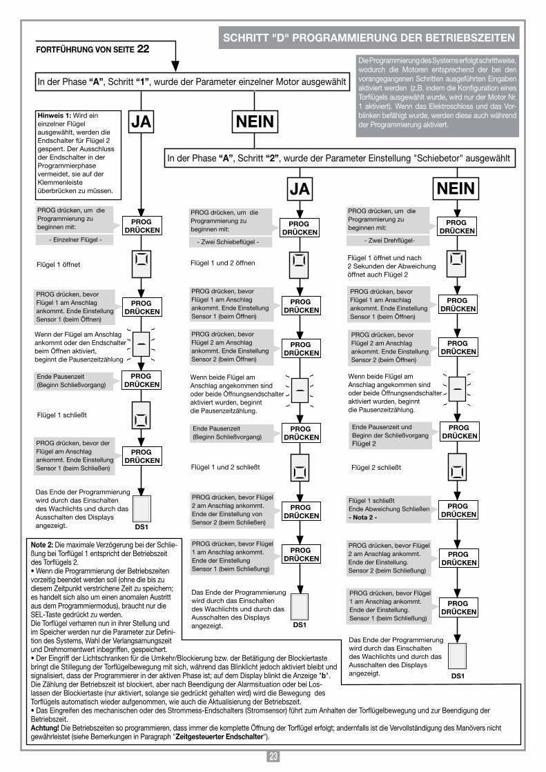
23
PROG drücken, um dieProgrammierung zu beginnen mit:
In der Phase “A”, Schritt “1”, wurde der Parameter einzelner Motor ausgewählt
JA
Flügel 1 öffnet
Ende Pausenzeit (Beginn Schließvorgang)
JA
PROG drücken, bevor Flügel 1 am Anschlag ankommt. Ende Einstellung Sensor 1 (beim Öffnen)
Wenn der Flügel am Anschlag ankommt oder den Endschalter beim Öffnen aktiviert, beginnt die Pausenzeitzählung
Flügel 1 schließt
PROG DRÜCKEN
Flügel 1 und 2 öffnen
Flügel 1 und 2 schließt
PROG DRÜCKEN
Das Ende der Programmierung wird durch das Einschalten des Wachlichts und durch das Ausschalten des Displays angezeigt.
PROG DRÜCKEN
Flügel 1 öffnet und nach 2 Sekunden der Abweichung öffnet auch Flügel 2
PROG DRÜCKEN
PROG drücken, bevor Flügel 2 am Anschlag ankommt. Ende Einstellung Sensor 2 (beim Öffnen)
Wenn beide Flügel am Anschlag angekommen sindoder beide Öffnungsendschalteraktiviert wurden, beginntdie Pausenzeitzählung.
PROG DRÜCKEN
PROG DRÜCKEN
Das Ende der Programmierung wird durch das Einschalten des Wachlichts und durch das Ausschalten des Displays angezeigt.
PROG DRÜCKEN
DS1
In der Phase “A”, Schritt “2”, wurde der Parameter Einstellung "Schiebetor" ausgewählt
PROG DRÜCKEN
PROG DRÜCKEN
PROG DRÜCKEN
PROG drücken, bevor derFlügel am Anschlag ankommt. Ende Einstellung Sensor 1 (beim Schließen)
PROG DRÜCKEN
Das Ende der Programmierung wird durch das Einschalten des Wachlichts und durch das Ausschalten des Displays angezeigt.
PROG DRÜCKEN
PROG DRÜCKEN
PROG DRÜCKEN
DS1
PROG DRÜCKEN
PROG drücken, bevor Flügel 1 am Anschlag ankommt. Ende Einstellung Sensor 1 (beim Öffnen)
PROG drücken, bevor Flügel 2 am Anschlag ankommt. Ende Einstellung Sensor 2 (beim Öffnen)
Ende Pausenzeit (Beginn Schließvorgang)
PROG drücken, bevor Flügel 2 am Anschlag ankommt. Ende der Einstellung von Sensor 2 (beim Schließen)
PROG drücken, bevor Flügel1 am Anschlag ankommt.Ende der Einstellung Sensor 1 (beim Schließung)
PROG DRÜCKEN
PROG drücken, bevor Flügel 1 am Anschlag ankommt. Ende Einstellung Sensor 1 (beim Öffnen)
Ende Pausenzeit und Beginn der Schließvorgang Flügel 2
Flügel 2 schließt
PROG DRÜCKEN
Flügel 1 schließtEnde Abweichung Schließen - Nota 2 -
PROG drücken, bevor Flügel 1 am Anschlag ankommt. Ende der Einstellung. Sensor 1 (beim Schließung)
PROG drücken, bevor Flügel 2 am Anschlag ankommt. Ende der Einstellung. Sensor 2 (beim Schließung)
DS1
Hinweis 1: Wird ein einzelner Flügel ausgewählt, werden die Endschalter für Flügel 2 gesperrt. Der Ausschluss der Endschalter in der Programmierphase vermeidet, sie auf der Klemmenleiste überbrücken zu müssen.
NEIN
- Einzelner Flügel -
PROG drücken, um dieProgrammierung zu beginnen mit:
- Zwei Schiebeflügel -
Wenn beide Flügel am Anschlag angekommen sindoder beide Öffnungsendschalteraktiviert wurden, beginntdie Pausenzeitzählung.
PROG drücken, um dieProgrammierung zu beginnen mit:
- Zwei Drehflügel-
NEIN
Die Programmierung des Systems erfolgt schrittweise, wodurch die Motoren entsprechend der bei den vorangegangenen Schritten ausgeführten Eingaben aktiviert werden (z.B. indem die Konfiguration eines Torflügels ausgewählt wurde, wird nur der Motor Nr. 1 aktiviert). Wenn das Elektroschloss und das Vor-blinken befähigt wurde, werden diese auch während der Programmierung aktiviert.
FORTFÜHRUNG VON SEITE 22SCHRITT "D" PROGRAMMIERUNG DER BETRIEBSZEITEN
Note 2: Die maximale Verzögerung bei der Schlie-ßung bei Torflügel 1 entspricht der Betriebszeit des Torflügels 2. •WenndieProgrammierungderBetriebszeitenvorzeitig beendet werden soll (ohne die bis zu diesem Zeitpunkt verstrichene Zeit zu speichern; es handelt sich also um einen anomalen Austritt aus dem Programmiermodus), braucht nur die SEL-Taste gedrückt zu werden. Die Torflügel verharren nun in ihrer Stellung und im Speicher werden nur die Parameter zur Defini-tion des Systems, Wahl der Verlangsamungszeit und Drehmomentwert inbegriffen, gespeichert.•DerEingriffderLichtschrankenfürdieUmkehr/Blockierungbzw.derBetätigungderBlockiertastebringt die Stillegung der Torflügelbewegung mit sich, während das Blinklicht jedoch aktiviert bleibt und signalisiert, dass der Programmierer in der aktiven Phase ist; auf dem Display blinkt die Anzeige "b". Die Zählung der Betriebszeit ist blockiert, aber nach Beendigung der Alarmsituation oder bei Los-lassen der Blockiertaste (nur aktiviert, solange sie gedrückt gehalten wird) wird die Bewegung des Torflügels automatisch wieder aufgenommen, wie auch die Aktualisierung der Betriebszeit. •DasEingreifendesmechanischenoderdesStrommess-Endschalters(Stromsensor)führtzumAnhaltenderTorflügelbewegungundzurBeendigungderBetriebszeit. Achtung! Die Betriebszeiten so programmieren, dass immer die komplette Öffnung der Torflügel erfolgt; andernfalls ist die Vervollständigung des Manövers nicht gewährleistet (siehe Bemerkungen in Paragraph "Zeitgesteuerter Endschalter").
24
1) AutomatischWird durch Einstellung der automatischen Wiederschließung gewählt (Schritt "6" der Programmierung, Nummer "6" konstant). Ausgehend vom Zustand des vollständig geschlossenen Tors leitet der Öffnungsbefehl einen kompletten Funktionszyklus ein, der mit der automatischen Verriegelung und dem zeitlichen Erlöschen des Wachlichts endet. Die automatische Schließung beginnt mit einer Verzögerung entsprechend der programmierten Pausenzeit nach beendigung des Öffnungsvorgangs oder ab dem Augenblick, in dem die Lichtschranken verursacht ein Zurücksetzen der Pausenzeit). Während der Pausenzeit blinkt auf dem Display das Symbol . Die Betätigung der Stopptaste während der Pausenzeit verhindert die automatische Wiederverschließung; das Display hört somit auf zu blinken.Das Eingreifen der mechanischen Endanschläge oder der Strommess-Endschalter verursacht die Blockierung des Torflügels. Die Kontrolllampe bleibt eingeschaltet, wenn das Tor nicht vollständig geschlossen ist.Merke: Das Wachlicht schaltet sich bei jedem Befehl an das System ein, und zwar sowohl per Kabel als auch per Funk; das Eingreifen der Lichtschranken während der Schließoperation hat keinen Einfluss auf die Zeitsteuerung des Wachlichts.
2) HalbautomatischWird durch Ausschalten der automatischen Wiederschließung gewählt (Schritt "6" der Programmierung, Nummer "6" blinkend).Der Arbeitszyklus wird durch separate Öffnungs- und Schließbefehle gesteuert. Sobald die komplette Öffnung abgeschlossen ist, wartet das System auf einen Schließbefehl per Funk oder Taste, um den Zyklus zu beenden. Das Eingreifen des Öffnungsendschalters verursacht ein Anhalten des Torflügels und die Beendigung des Öffnungsvorgangs. Nach Beendigung des Öffnungsvorgangs schaltet sich das Wachlicht nach Ablauf der vorab festgelegten Zeit aus. Die Kontrolllampe bleibt eingeschaltet, wenn das Tor nicht vollständig geschlossen ist.
BEGRENZTE ÖFFNUNGWird für den Torflügel 1 ausgeführt; Falls das System für zwei Torflügel konfiguriert ist, wird der Torflügel 1 vollkommen geöffnet. Falls das System für einen Torflügel konfigu-riert ist, wird der Torflügel 1 teilweise geöffnet (zirka 1/3 der Öffnungsweite). Der Befehl kann nur bei vollkommen geschlossen Torflügeln ausgeführt werden. Wenn während der begrenzten Öffnung erneut der Befehl "TAL" gegeben wird, wird der Torflügel 1 blockiert. Bei der nachfolgenden Befehlseingabe wird dessen Schließung ausgeführt, wobei bis zur vollständigen Schließung kein Befehl mehr ausgeführt wird.
WACHLICHT / FUNK-AUSGANG CH2Die Anschlussklemmen "7" und "8" entsprechen den gemein/normalerweise geöffnete Kontakten eines Relais. Es kann mit dem normalen "Wachlicht"-Modus aktiviert werden (mit für die programmierte Zeit geschlossenem Kontakt) oder direkt durch den zweiten Funkkanal, der durch die mit der Steuereinheit integrierten Dekodifizierung wählbar ist ( Brücke "J1"). Die Anschlussklemmen "7" und "8" bieten nur einen spannungs-freien Kontakt und liefern keine Stromspannung an externe Stromverbraucher. Dies bedeutet, dass für die Verwendung des Wachlichtes der Schaltkreis extra versorgt und der Kontakt als einfacher Schalter verwendet werden muss.
Achtung! Auf der Schaltkreis des Programmierers ist die 230Vac-Spannung nicht vorhanden. Auf ihr gibt es nur Niederspannungsstrom. In Entsprechend der Stromschutzbestimmungen, die bestimmte Isolierung zwischen den Leitungs-bahnen mit hoher Spannung (230 Vac) und mit niedriger Spannung (24 Vac) vorschreiben, dass der Anschluss eines Schaltkreises mit einer angewendeten Spannung von 230 Vac an die Anschlussklemmen 7 und 8 nicht möglich ist. Die höchste zugelassene Spannung beträgt 30 Vac/dc.
MODALITÄT "MANUELLER BETRIEB"Kann verwendet werden, um die Torflügel in der Schließung (oder der Öffnung) unter direkter Kontrolle des Betriebers zu bewegen. In dieser Betriebsmodalität funktionieren die Sicherheitsvorrichtung FTC_I, FTC_S und TB solange sie sich in Alarmstellung befinden. Die Installationsarbeiten werden dadurch vereinfacht, und vor der System-programmierung sind die Torflügel vollkommen geschlossen. In diesem Modus bleibt die LED "L3" (gekennzeichnet durch "UPL") an. Die Modalität "manueller Betrieb" kann auch bei Batteriebetrieb ausgeführt werden. Die Motoren werden mit der höchsten Spannung (Beharrungsgeschwindigkeit) unabhängig davon versorgt, ob die Verlang-samung eingestellt ist oder nicht. Die Sicherheitsvorrichtungen FTC_I (nur bei der Schließung, unabhängig von der Wahl der Systemparameterbestimmung bei Schritt "C") und FTC_S werden wie die Endschalter und die Stromsensoren verwaltet.
• SchließvorgangWird durch Gedrückthalten der Taste "SEL" erzielt. Die Schliessbewegung stoppt durch:- Loslassen der Taste "SEL" (kein "manueller Betrieb" mehr).- Aktivierung der Blockiertaste "TB": um die Schliessbewegung wieder aufzunehmen,
muss die Taste "SEL" zunächst losgelasen und anschließend erneut gedrückt werden.
- Aktivierung des Schließendanschlags: das Betätigen der Taste "SEL" verursacht nicht die Schließung, sondern lediglich das Einschalten des Wachlichts.
• ÖffnungsvorgangWird durch Gedrückthalten der Taste "SEL" und sofortige anschließende Betätigung der Taste "PROG" erzielt.
Die Öffnungsbewegung stoppt durch:- Loslassen beider Tasten (kein manueller Betrieb mehr). - Aktivierung der Blockiertaste "TB": um die Öffnungsbewegung wieder aufzuneh-
men, müssen beide Tasten zunächst losgelassen und anschließend erneut gedrückt werden.
- Aktivierung des Öffnungsendanschlags.
• UmkehrderBewegungWährend der Schließphase: um den Öffnungsvorgang einzuleiten, die Taste "PROG" drücken.Während der Öffnungsphase: um den Schließvorgang einzuleiten, die Taste "PROG" loslassen.
• WachlichtDas Wachlicht ist während des gesamten Zeit des manuellen Betriebs eingeschaltet. Es schaltet sich auch ein, wenn versucht wird, einen Befehl zu senden, seine Ausführung durch den Endanschlag jedoch verhindert wird.
NEUEINSTELLUNG DER STROMSENSORENDie Messung des von den Motoren aufgenommenen Stromes wird so ausgeführt, dass eventuell umweltbedingt auftretende geringere Variationen ausgeglichen werden können. In diesem Falle wird auf dem Display eine zusätzliche Angabe bestehend aus einem blinkenden Strich (je schneller blinkt desto größer die sich in der Ausführung befindliche Kompensation ist) erscheinen. Der Strich wird sich auf der linken Seite des Displays für den Stromsensor 1 und auf der rechten Seite für den Stromsensor 2 befinden (siehe "Angaben auf dem display", Seite 21). Bei jeder Blockierung der Bewegung, Umkehrbewegung inbegriffen, wird die Kompensation rückgestellt und neu berechnet, um eine fortlaufende Aktualisierung zu haben.
WARNSIGNALE1) Von EEPROM eingeladene Parameter falsch.Auf dem Display blinkt der Buchstabe und das System ist blockiert. Man kann jetzt lediglich in den Programmiermodus gehen, um das System neu zu programmieren. Sollte das Hindernis nach wiederholter Operation erneut auftreten, liegt das Problem beim EEPROM (kann nicht korrekt speichern). Das System von der Stromzufuhr trennen, nach einigen Sekunden wieder einschalten und neuprogrammierung versuchen.
2) Öffnungs-/Schließendschalter gleichzeitig aktiviert.Auf dem Display erscheint der Buchstabe und das System ist blockiert. Das Blinklicht wird ungefähr 3 Sekunden lang aktiviert, mit einer Wiederholungszeit von 6 Sekunden, und blinkt dann weiter. Das System von der Stromzufuhr trennen und den Zustand der Endschalter prüfen. Dann das System wieder an Strom anschließen.
ZEITGESTEUERTER ENDSCHALTER Die Steuerung der Arbeitszeiten ermöglicht die kontrolle der Torflügelposition.Bei Stromausfall vergisst der Programmierer, außer wenn einer der beiden End-schalter aktiv ist, die von den Torflügeln erreichte Stellung, die nun als "vollkommen geschlossen" angesehen werden. Die Öffnung kann somit wieder eingeleitet werden. Die Betriebszeitenverwaltung stellt sicher, dass der nachfolgende Schließvorgang wieder komplett ausgeführt wird. Bei wiederholter Laufrichtungsumkehr mit entsprechendem Stillstand der Bewegung und langsamen Start könnte es zu Veränderungen in der Zeitüberwachung und zu einem Aussetzen der Verlangsamung vor Ankunft am Endanschlag kommen. Der korrekte Betrieb wird bei dem anschließenden Manöver wieder hergestellt.
Es besteht die Möglichkeit, den Motor mittels der Funksteuerung fernzusteuern: die sequentielle Steuerfunktion "öffnen-blockieren-schließen-blockieren" oder "öffnen-schließen" (wählbar) steht zur Verfügung und kann unterschiedslos mit irgendeinem der zur Verfügung stehenden Kanäle ausgeführt werden. Wenn bei der Festlegung der Systemparameter die Nummer "3" blinkend gewählt wird, steht ein zweiter Kanal mit einem C-N.O.-Kontakt am Ausgang (Anschlussklemmen 7, 8) zur Verfügung.
SpeichermodulHerausnehmbar, verfügt über nicht flüchtigen EEPROM-Speicher, beinhaltet die Sendercodes und ermöglicht die Speicherung von 300 Codes (300 Kanaltasten). Die Codes verbleiben im Speicher auch in Abwesenheit der Stromversorgung.
Bevor die erste Speicherung vorgenommen wird, muss zuerst der Speicher vollkommen gelöscht werden.
Achtung! Falls die elektronische Karte im Falle eines Defekts ausgewechselt werden muss, kann das Speichermodul aus dieser herausgenommen und in die neue Karte wie in Abb. 1, Detail A aufgezeigt eingesteckt werden.
VERWALTUNG DER SENDERCODESLED-Kontrollleuchten "L2" (Abb.1): Schnelles Blinken: Löschen eines einzelnen CodesLangsames Blinken: Speicherung eines CodesDauerleuchtend: Speicher voll.
Speicherung eines Kanals (Abb. 1):1. Die Taste "P3" MEMO gedrückt halten; die LED "L2" blinkt langsam.2. Den Sender auf dem zu speichernden Kanal gleichzeitig aktivieren.
FUNKTIONSARTEN
FERNBEDIENUNG S449
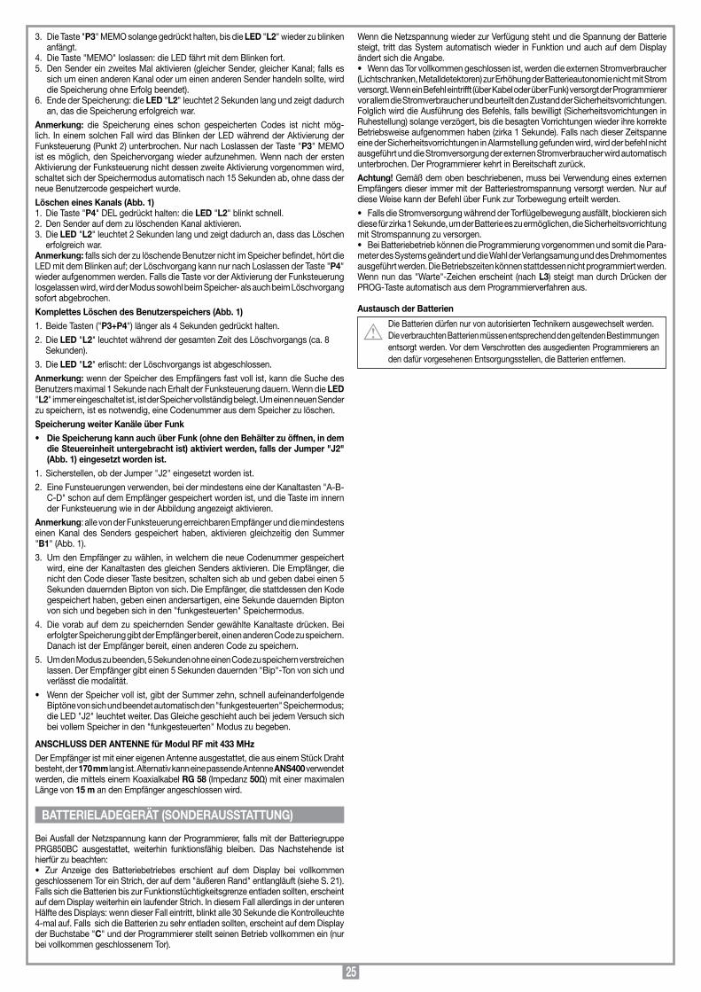
25
3. Die Taste "P3" MEMO solange gedrückt halten, bis die LED "L2" wieder zu blinken anfängt.
4. Die Taste "MEMO" loslassen: die LED fährt mit dem Blinken fort.5. Den Sender ein zweites Mal aktivieren (gleicher Sender, gleicher Kanal; falls es
sich um einen anderen Kanal oder um einen anderen Sender handeln sollte, wird die Speicherung ohne Erfolg beendet).
6. Ende der Speicherung: die LED "L2" leuchtet 2 Sekunden lang und zeigt dadurch an, das die Speicherung erfolgreich war.
Anmerkung: die Speicherung eines schon gespeicherten Codes ist nicht mög-lich. In einem solchen Fall wird das Blinken der LED während der Aktivierung der Funksteuerung (Punkt 2) unterbrochen. Nur nach Loslassen der Taste "P3" MEMO ist es möglich, den Speichervorgang wieder aufzunehmen. Wenn nach der ersten Aktivierung der Funksteuerung nicht dessen zweite Aktivierung vorgenommen wird, schaltet sich der Speichermodus automatisch nach 15 Sekunden ab, ohne dass der neue Benutzercode gespeichert wurde.
Löschen eines Kanals (Abb. 1)1. Die Taste "P4" DEL gedrückt halten: die LED "L2" blinkt schnell.2. Den Sender auf dem zu löschenden Kanal aktivieren.3. Die LED "L2" leuchtet 2 Sekunden lang und zeigt dadurch an, dass das Löschen
erfolgreich war. Anmerkung: falls sich der zu löschende Benutzer nicht im Speicher befindet, hört die LED mit dem Blinken auf; der Löschvorgang kann nur nach Loslassen der Taste "P4" wieder aufgenommen werden. Falls die Taste vor der Aktivierung der Funksteuerung losgelassen wird, wird der Modus sowohl beim Speicher- als auch beim Löschvorgang sofort abgebrochen.
Komplettes Löschen des Benutzerspeichers (Abb. 1)1. Beide Tasten ("P3+P4") länger als 4 Sekunden gedrückt halten.
2. Die LED "L2" leuchtet während der gesamten Zeit des Löschvorgangs (ca. 8 Sekunden).
3. Die LED "L2" erlischt: der Löschvorgangs ist abgeschlossen.
Anmerkung: wenn der Speicher des Empfängers fast voll ist, kann die Suche des Benutzers maximal 1 Sekunde nach Erhalt der Funksteuerung dauern. Wenn die LED "L2" immer eingeschaltet ist, ist der Speicher vollständig belegt. Um einen neuen Sender zu speichern, ist es notwendig, eine Codenummer aus dem Speicher zu löschen.
Speicherung weiter Kanäle über Funk• DieSpeicherungkannauchüberFunk(ohnedenBehälterzuöffnen,indem
die Steuereinheit untergebracht ist) aktiviert werden, falls der Jumper "J2" (Abb. 1) eingesetzt worden ist.
1. Sicherstellen, ob der Jumper "J2" eingesetzt worden ist.
2. Eine Funsteuerungen verwenden, bei der mindestens eine der Kanaltasten "A-B-C-D" schon auf dem Empfänger gespeichert worden ist, und die Taste im innern der Funksteuerung wie in der Abbildung angezeigt aktivieren.
Anmerkung: alle von der Funksteuerung erreichbaren Empfänger und die mindestens einen Kanal des Senders gespeichert haben, aktivieren gleichzeitig den Summer "B1" (Abb. 1).
3. Um den Empfänger zu wählen, in welchem die neue Codenummer gespeichert wird, eine der Kanaltasten des gleichen Senders aktivieren. Die Empfänger, die nicht den Code dieser Taste besitzen, schalten sich ab und geben dabei einen 5 Sekunden dauernden Bipton von sich. Die Empfänger, die stattdessen den Kode gespeichert haben, geben einen andersartigen, eine Sekunde dauernden Bipton von sich und begeben sich in den "funkgesteuerten" Speichermodus.
4. Die vorab auf dem zu speichernden Sender gewählte Kanaltaste drücken. Bei erfolgter Speicherung gibt der Empfänger bereit, einen anderen Code zu speichern. Danach ist der Empfänger bereit, einen anderen Code zu speichern.
5. Um den Modus zu beenden, 5 Sekunden ohne einen Code zu speichern verstreichen lassen. Der Empfänger gibt einen 5 Sekunden dauernden "Bip"-Ton von sich und verlässt die modalität.
• WennderSpeichervollist,gibtderSummerzehn,schnellaufeinanderfolgendeBiptöne von sich und beendet automatisch den "funkgesteuerten" Speichermodus; die LED "J2" leuchtet weiter. Das Gleiche geschieht auch bei jedem Versuch sich bei vollem Speicher in den "funkgesteuerten" Modus zu begeben.
ANSCHLUSS DER ANTENNE für Modul RF mit 433 MHzDer Empfänger ist mit einer eigenen Antenne ausgestattet, die aus einem Stück Draht besteht, der 170 mm lang ist. Alternativ kann eine passende Antenne ANS400 verwendet werden, die mittels einem Koaxialkabel RG 58 (Impedanz 50Ω) mit einer maximalen Länge von 15 m an den Empfänger angeschlossen wird.
Bei Ausfall der Netzspannung kann der Programmierer, falls mit der Batteriegruppe PRG850BC ausgestattet, weiterhin funktionsfähig bleiben. Das Nachstehende ist hierfür zu beachten:• Zur Anzeige des Batteriebetriebes erschient auf dem Display bei vollkommengeschlossenem Tor ein Strich, der auf dem "äußeren Rand" entlangläuft (siehe S. 21). Falls sich die Batterien bis zur Funktionstüchtigkeitsgrenze entladen sollten, erscheint auf dem Display weiterhin ein laufender Strich. In diesem Fall allerdings in der unteren Hälfte des Displays: wenn dieser Fall eintritt, blinkt alle 30 Sekunde die Kontrolleuchte 4-mal auf. Falls sich die Batterien zu sehr entladen sollten, erscheint auf dem Display der Buchstabe "C" und der Programmierer stellt seinen Betrieb vollkommen ein (nur bei vollkommen geschlossenem Tor).
BATTERIELADEGERÄT (SONDERAUSSTATTUNG)
Wenn die Netzspannung wieder zur Verfügung steht und die Spannung der Batterie steigt, tritt das System automatisch wieder in Funktion und auch auf dem Display ändert sich die Angabe.• WenndasTorvollkommengeschlossenist,werdendieexternenStromverbraucher(Lichtschranken, Metalldetektoren) zur Erhöhung der Batterieautonomie nicht mit Strom versorgt. Wenn ein Befehl eintrifft (über Kabel oder über Funk) versorgt der Programmierer vor allem die Stromverbraucher und beurteilt den Zustand der Sicherheitsvorrichtungen. Folglich wird die Ausführung des Befehls, falls bewilligt (Sicherheitsvorrichtungen in Ruhestellung) solange verzögert, bis die besagten Vorrichtungen wieder ihre korrekte Betriebsweise aufgenommen haben (zirka 1 Sekunde). Falls nach dieser Zeitspanne eine der Sicherheitsvorrichtungen in Alarmstellung gefunden wird, wird der befehl nicht ausgeführt und die Stromversorgung der externen Stromverbraucher wird automatisch unterbrochen. Der Programmierer kehrt in Bereitschaft zurück.
Achtung! Gemäß dem oben beschriebenen, muss bei Verwendung eines externen Empfängers dieser immer mit der Batteriestromspannung versorgt werden. Nur auf diese Weise kann der Befehl über Funk zur Torbewegung erteilt werden.
• FallsdieStromversorgungwährendderTorflügelbewegungausfällt,blockierensichdiese für zirka 1 Sekunde, um der Batterie es zu ermöglichen, die Sicherheitsvorrichtung mit Stromspannung zu versorgen.• BeiBatteriebetriebkönnendieProgrammierungvorgenommenundsomitdiePara-meter des Systems geändert und die Wahl der Verlangsamung und des Drehmomentes ausgeführt werden. Die Betriebszeiten können stattdessen nicht programmiert werden. Wenn nun das "Warte"-Zeichen erscheint (nach L3) steigt man durch Drücken der PROG-Taste automatisch aus dem Programmierverfahren aus.
Austausch der Batterien
Die Batterien dürfen nur von autorisierten Technikern ausgewechselt werden.Die verbrauchten Batterien müssen entsprechend den geltenden Bestimmungen entsorgt werden. Vor dem Verschrotten des ausgedienten Programmierers an den dafür vorgesehenen Entsorgungsstellen, die Batterien entfernen.
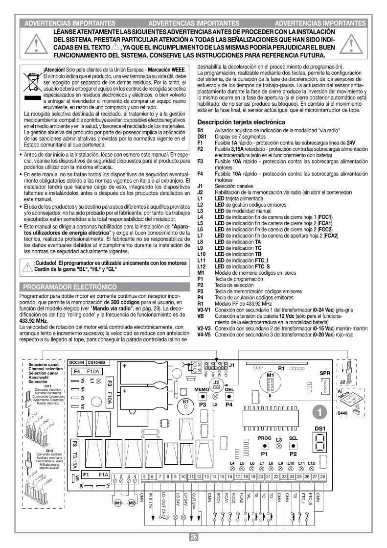
26
ADVERTENCIAS IMPORTANTES ADVERTENCIAS IMPORTANTES ADVERTENCIAS IMPORTANTES
deshabilita la deceleración en el procedimiento de programación). La programación, realizable mediante dos teclas, permite la configuración del sistema, de la duración de la fase de deceleración, de los sensores de esfuerzo y de los tiempos de trabajo-pausa. La actuación del sensor antia-plastamiento durante la fase de cierre produce la inversión del movimiento y lo mismo ocurre en la fase de apertura (si el cierre posterior automático está habilitado: de no ser así produce su bloqueo). En cambio si el movimiento está en la fase final, el sensor actúa igual que el microinterruptor de tope.
Descripción tarjeta electrónicaB1 Avisador acústico de indicación de la modalidad "vía radio"DS1 Display de 7 segmentosF1 Fusible 1A rápido - protección contra las sobrecargas línea de 24V F2 Fusible 3,15A retardado - protección contra las sobrecargas alimentación
electrocerradura (sólo en el funcionamiento con batería) F3 Fusible 10A rápido - protección contra las sobrecargas alimentación
motores F4 Fusible 10A rápido - protección contra las sobrecargas alimentación
motoresJ1 Selección canales J2 Habilitación de la memorización vía radio (sin abrir el contenedor)L1 LED tarjeta alimentadaL2 LED de gestión códigos emisoresL3 LED de modalidad manualL4 LED de indicación fin de carrera de cierre hoja 1 (FCC1)L5 LED de indicación fin de carrera de cierre hoja 2 (FCA1)L6 LED de indicación fin de carrera de cierre hoja 2 (FCC2)L7 LED de indicación fin de carrera de apertura hoja 2 (FCA2)L8 LED de indicación TAL9 LED de indicación TCL10 LED de indicación TBL11 LED de indicación FTC_IL12 LED de indicación FTC_SM1 Módulo de memoria códigos emisoresP1 Tecla de programaciónP2 Tecla de selecciónP3 Tecla de memorización códigos emisores P4 Tecla de anulación códigos emisoresR1 Módulo RF de 433.92 MHz V0-V1 Conexión con secundario 1 del transformador (0-24 Vac) gris-grisVB Conexión a tensión de batería 12 Vdc (sólo para el funciona- miento de la electrocerradura en la modalidad batería)V2-V3 Conexión con secundario 2 del transformador (0-15 Vac) marrón-marrónV4-V5 Conexión con secundario 3 del transformador (0-20 Vac) rojo-rojo
¡Atención! Solo para clientes de la Unión Europea - Marcación WEEE.El símbolo indica que el producto, una vez terminada su vida útil, debe ser recogido por separado de los demás residuos. Por lo tanto, el usuario deberá entregar el equipo en los centros de recogida selectiva especializados en residuos electrónicos y eléctricos, o bien volverlo a entregar al revendedor al momento de comprar un equipo nuevo equivalente, en razón de uno comprado y uno retirado.
La recogida selectiva destinada al reciclado, al tratamiento y a la gestión medioambiental compatible contribuye a evitar los posibles efectos negativos en el medio ambiente y en la salud, y favorece el reciclado de los materiales. La gestión abusiva del producto por parte del posesor implica la aplicación de las sanciones administrativas previstas por la normativa vigente en el Estado comunitario al que pertenece.
•Antes de dar inicio a la instalación, léase con esmero este manual. En espe-cial, véanse los dispositivos de seguridad dispuestos para el producto para poderlos utilizar con la máxima eficacia.
•Enestemanualnosetratantodoslosdispositivosdeseguridadeventual-mente obligatorios debido a las normas vigentes en italia o al extranjero. El instalador tendrá que hacerse cargo de esto, integrando los dispositivos faltantes e instalándolos antes o después de los productos detallados en este manual.
•Elusodelosproductosysudestinoparausosdiferentesaaquéllosprevistosy/o aconsejados, no ha sido probado por el fabricante, por tanto los trabajos ejecutados están sometidos a la total responsabilidad del instalador.
•Estemanualsedirigeapersonashabilitadasparalainstalaciónde"Apara-tos utilizadores de energía eléctrica" y exige el buen conocimiento de la técnica, realizada profesionalmente. El fabricante no se responsabiliza de los daños eventuales debidos al incumplimiento durante la instalación de las normas de seguridad actualmente vigentes.
¡Cuidado! El programador es utilizable únicamente con los motores Cardin de la gama "BL", "HL" y "GL"
Programador para doble motor en corriente continua con receptor incor-porado, que permite la memorización de 300 códigos para el usuario, en función del modelo elegido (ver "Mando vía radio", en pág. 29). La deco-dificación es del tipo 'rolling code' y la frecuencia de funcionamiento es de 433.92 MHz. La velocidad de rotación del motor está controlada electrónicamente, con arranque lento e incremento sucesivo; la velocidad se reduce con antelación respecto a su llegado al tope, para conseguir la parada controlada (si no se
LÉANSE ATENTAMENTE LAS SIGUIENTES ADVERTENCIAS ANTES DE PROCEDER CON LA INSTALACIÓN DEL SISTEMA. PRESTAR PARTICULAR ATENCIÓN A TODAS LAS SEÑALIZACIONES QUE HAN SIDO INDI-CADAS EN EL TExTO , YA QUE EL INCUMPLIMIENTO DE LAS MISMAS PODRÍA PERJUDICAR EL BUEN FUNCIONAMIENTO DEL SISTEMA. CONSERVE LAS INSTRUCCIONES PARA REFERENCIA FUTURA.
PROGRAMADOR ELECTRÓNICO
Co
llegam
enti scheda b
ase
PR
G852
19-12-2008
DC
0445D
escription :
Prod
uct Cod
e :
Date:
Draw
ing numb
er :
P.J.Heath
CA
RD
IN E
LE
TT
RO
NIC
A S
.p.A
- 31020 San Vend
emiano
(TV
) Italy - via Raffaello
, 36 Tel: 0438/401818 Fax: 0438/401831
Draft :
All rights reserved
. Unauthorised
copying or use of the inform
ation contained in this d
ocument is p
unishable b
y law
PR
G852
F2 T3.15A
CS1046B DC0344
F1 F1A
2930
P4P3
DELMEMO
L2
DS1
V5
V4
V3
V2
ELS
12V
1098765 161514131211 222120191817 282726252423
LC- O
UT C
H2
LS 24V
CM
N
LP 24V
OU
T 24V
CM
N
FCC
1
FCA
1
FCC
2
FCA
2
TAL
TA TC TD CM
N
CM
N
TB FTC_I
FTC_S
CM
N
F4 F10A
F3 F10A
P2P1
SELPROG L3
L4 L5 L6 L7 L8 L9 L10 L11 L12
L1
VB
V1V0
CHA
CHB
CHC
CHD
CH 1Comando dinamicoDynamic command
Commande dynamiqueDynamische Steuerung
Mando dinámico
Selezione canaliChannel selectionSélection canalKanalwahlSelección
CH 2Comando ausiliarioAuxiliary command
Commande auxiliareHilfssteuerungMando auxiliar
CHA
CHBCHC
CHD
J1
CH
A
CH
B
CH
C
CH
D
M1 M2
2 31 4
R1M1
S449
24C16A)
J2 J2
B1
SPR
1

27
Comprobar, antes de realizar la conexión eléctrica, que la tensión y la frecuencia indicadas en la placa de características coincidan con las de la instalación de alimentación. Entre la centralita de mando y la red se debe disponer un interruptor omnipolar cuya distancia de apertura de los contactos debe ser de 3 mm como mínimo.
• Conectarloscablesdemandoylosprocedentesdelosdispositivosdeseguridad.• Conectar el cable de alimentación al dispositivo, mediante la bornera voladiza (que
ya está conectada al primario del transformador, hilos blanco-negro).• No utilizar cable con conductores de aluminio; no estañar el extremo de los cables
que se deben introducir en la bornera; utilizar un cable marcado con T min 85°C resistente a los agentes atmosféricos.
• Los conductores se deben fijar adecuadamente cerca de la bornera de modo que dicha fijación cierre tanto el aislamiento como el conductor (es suficiente una abrazadera).
Conexiones de la bornera 1-2 Salida motor 1: en apertura: positivo en borne 1 y negativo en borne 2 en cierre: negativo en borne 1 y positivo en borne 23-4 Salida motor 2: en apertura: positivo en borne 3 y negativo en borne 4 en cierre: negativo en borne 3 y positivo en borne 45 Comunes para todas las entradas y salidas6 Salida para electrocerradura (pilotada en continua) 12 Vdc -15 W; debe ser del tipo
basculante (no de reposición automática) puesto que la activación dura 1 segundo.7-8 Salida (contacto puro, N.A.) para activación luz de servicio (alimentada por
separado, Vmax= 30 Vac/dc: Imax=1A) o bien para segundo canal de radio. La selección se hace durante la programación.
9 Salida indicador luminoso 24 Vac 3 W 10 Salida para relampagueador 24 Vac 10 W (activación luz fija o intermitente)11 Salida para alimentación cargas exteriores 24 Vac 10 W 12-13 Comunes para todas las entradas y salidas14 FCC1 (contacto N.C.) entrada fin de carrera de cierre de la hoja 115 FCA1 (contacto N.C.) entrada fin de carrera de apertura de la hoja 116 FCC2 (contacto N.C.) entrada fin de carrera de cierre de la hoja 217 FCA2 (contacto N.C.) entrada fin de carrera de apertura de la hoja 218 TAL (contacto N.A.) entrada tecla de apertura limitada 19 TA (contacto N.A.) entrada tecla de apertura20 TC (contacto N.A.) entrada tecla de cierre21 TD Entrada (contacto N.A.) para mando secuencial (apertura-bloqueo-cierre-
bloqueo) o bien apertura-cierre con inversión sólo para el cierre, en función de las programaciones efectuadas en el programa)
22-23 Comunes para todas las entradas y salidas24 TB (contacto N.C.) entrada tecla de bloqueo25 FTC_I (contacto N.C.) entrada para los dispositivos de seguridad (fotocélula
de inversión durante el cierre). La apertura del contacto, después de actuar los dispositivos de seguridad, durante la fase de cierre, realiza la inversión del movimiento.
26 FTC_S (contacto N.C.) entrada para dispositivos de seguridad (fotocélula de parada). Al volver a la condición de reposo, después del tiempo de pausa, el movimiento se reanuda en la fase de cierre (sólo si está en la modalidad automática).
27-28 Comunes para todas las entradas y salidas 29 Central antena radiorreceptor; conectar un hilo rígido de 17cm o bien antena
exterior de ANS400 mediante cable coaxial (RG58 imp. 50Ω)30 Masa antena radiorreceptor
TODOS LOS CONTACTOS N.C. QUE NO SE UTILICEN DEBEN PUENTEARSE (no es necesario para los microinterruptores de tope deshabilitados en fase de programación).Suministrar alimentación al circuito y comprobar que el estado de los LED rojos de señalización es el que se da a continuación:- L1 LED de alimentación circuito encendido- L4 LED de fin de carrera de cierre hoja 1 "FCC1" encendido*- L5 LED de fin de carrera de apertura hoja 1 "FCA1" encendido*- L6 LED de fin de carrera de cierre hoja 2 "FCC2" encendido*- L7 LED de fin de carrera de apertura hoja 2 "FCA2" encendido*- L8 LED de señalización tecla de apertura "TA" apagado- L9 LED de señalización tecla de cierre "TC" apagado- L10 LED de señalización tecla de bloqueo "TB" encendido*- L11 LED de seguridad fotocélulas de inversión "FTC_I" encendido*- L12 LED de seguridad fotocélulas de parada "FTC_S" encendido*
* Los LEDs están encendidos si el dispositivo de seguridad correspondiente no ésta activado (dependiendo de la posición de la hoja y de la presencia o menos de los microinterruptores de tope). Comprobar que al activar los dispositivos de seguridad se apaguen los LEDs acoplados a éstos. En caso de que el LED de alimentación L1 no se encienda, comprobar los contactos del correspondiente dispositivo de seguridad conectado o bien controla que los contactos de los dispositivos de seguridad sin utilizar están conectados en puente en la bornera.
alarma para ambos topes mecánicos activados al mismo tiempo
error en los parámetros almacenados en la memoria
bloqueo en la modalidad de programación de los tiempos (debido a: TB, FTC_I, FTC_S)
definición de la configuración del sistema
fase de espera después de la programación de los parámetros
fase de espera después de la programación de la deceleración
fase de espera después de la programación del nivel de los sensores de corriente
tiempo de deceleración (valor 1)
nivel 1 para el sensor de corriente
programación de los tiempos de trabajo
fase de apertura
bloqueo
pausa para el cierre posterior automático (sólo si está habilitado)
fase de cierre
actualización del sensor de corriente hoja 1 (en programación)
actualización del sensor de corriente hoja 2 (en programación)
actualización de ambos sensores de corriente; hoja 1 - 2 (en programación)
Apertura + compensación sensor 1
Apertura + compensación sensor 2
Cierre + compensación sensor 1
Cierre + compensación sensor 2
Modalidad batería con batería cargada
Modalidad batería con batería descargada
Bloqueo para batería descargada
CONExIÓN ELÉCTRICA INDICACIONES EN EL DISPLAY

28
Antes de empezar, comprobar que las hojas están cerradas, el display por LED está apagado y los LEDs L10, L11 y L12 están todos encendidos.
Los LEDs L4 y L6 (si se han incorporado los microinterruptores de cierre hojas 1 y 2) están apagados (microinterruptor de tope para el cierre activado).
Procedimiento de programación (fijación entradas programador, del sensor de corriente y de los tiempos de trabajo)
PULSAR SEL
PULSARPROG
Motorindividual
Configuracióncon hoja batiente
Configuracióncon hoja corredera
FUNCIÓNACTIVA
Bornes 7,8luz de servicio
Bornes 7,8salida CH2 radio
TD: apertura-cierre
TD: apertura-bloqueo
cierre-bloqueo
Intermitenciaprevia
habilitada
Intermitenciaprevia
deshabilitada
Finales de carreramotor 1
habilitada
Finales de carreramotor 1
deshabilitada
DS1MANTENER APRETADO DURANTE UNOS 4 SEGUNDOS LA TECLA “PROG”: EN EL DISPLAY APARECE LA LETRA "d" INDICANDO LA DEFINICIÓN DE LOS PARÁMETROS DEL SISTEMA
FUNCIÓNACTIVA
PULSARSEL
1...20 s
ESPERAR UNOS 20 SEGUNDOS SIN PULSAR NINGUNA TECLA: EL PRG GUARDA LAS ENTRADAS QUE HAN SIDO FIJADAS HASTA ESTE MOMENTO Y SALE DE LA PROGRAMACIÓN.
DESPUÉS DE 1 SEGUNDO, SE VISUALIZA LA CIFRA "1" (PRIMER PASO DE LA PROGRAMACIÓN) QUE PODRÁ RESULTAR INTERMITENTE O FIJA
Nota 1
Electrocerradurahabilitada
Electrocerraduradeshabilitada
Cierre automáticohabilitada
Cierre automático
deshabilitada
LA PULSACIÓN DE LA TECLA "PROG" LLEVA A LA FASE "C". PROGRAMACIÓN DEL SENSOR DE CORRIENTE. LOS VALOR SELECCIONABLES VAN DA 1 A 3.
Doblemotor
PULSAR SEL
Finales de carreramotor 2
habilitada
Finales de carreramotor 2
deshabilitada
Relampagueadorcon electrónica
a bordo
Relampagueadoractivada desde
el PRG
Deceleración habilitada
Deceleración deshabilitada
Indicador luminoso nocentelleante
Indicador luminoso no centelleante
FTC_Iactivadas tambiéndurante bloqueo
FTC_Iactivadas sólo enla fase de cierre
PULSARPROG
Nota 2
Nota 3
Nota 1 La inversión del movimiento se obtiene sólo en la fase de cierre. Nota 2 El indicador luminoso centellea lentamente durante la apertura de la cancilla,
rápidamente durante el cierre de la misma, permanece encendido cuando no está totalmente cerrada y se apaga cuando la misma está totalmente cerrada.
Nota 3 Si las fotocélulas están en condición de alarma y la cancilla está en estado de bloqueo, el sistema no acepta ningún mando de movimiento (ni siquiera de apertura
PULSARPROG
PULSAR SEL
PULSARPROG
PULSAR SEL
PULSARPROG
PULSAR SEL
PULSARPROG
PULSAR SEL
PULSARPROG
PULSAR SEL
PULSARPROG
PULSAR SEL
PULSARPROG
PULSAR SEL
PULSARPROG
PULSAR SEL
PULSARPROG
PULSAR SEL
PULSARPROG
PULSAR SEL
PULSARPROG
PULSAR SEL
PULSARPROG
PULSARSEL
ALTERNOS
PULSARPROG
PULSARPROG
ALTERNOSPULSARPROG
VALOR FIJO
PULSARSEL
ALTERNOSVALOR
FIJO
PULSARSEL
VALOR FIJO
selección3 segundos
selección4,5
segundos
selección6 segundos
PULSARPROG
PULSARSEL
ESPERAR UNOS 20 SEGUNDOS SIN PULSAR NINGUNA TECLA: EL PRG GUARDA LAS ENTRADAS QUE HAN SIDO FIJADAS HASTA ESTE MOMENTO Y SALE DE LA PROGRAMACIÓN.
¡Cuidado! La selección de R1, R2 y R3 se debe hacer aunque se haya deshabilitado la deceleración: de hecho es necesario establecer el tiempo durante el cual el sensor de corriente actúa como fin de carrera en proximidad de alcanzar el tope. Se aconseja seleccionar un plazo mínimo de 4,5 segundos.La selección debe consentir la parada suave del movimiento, limitando a lo esencial el recorrido a velocidad reducida.
1...20 s
PULSARSEL
ALTERNOS
PULSARPROG
PULSARPROG
ALTERNOS
PULSARPROG
VALOR FIJO
PULSARSEL
ALTERNOSVALOR
FIJO
PULSARSEL
VALOR FIJO
parmínimo
parmedio
parmáximo
PULSARPROG
PULSARSEL
ESPERAR UNOS 20 SEGUNDOS SIN PULSAR NINGUNA TECLA: EL PRG GUARDA LAS ENTRADAS QUE HAN SIDO FIJADAS HASTA ESTE MOMENTO Y SALE DE LA PROGRAMACIÓN.
¡Cuidado! El programador ejecuta el control de la absorción del motor, detectando el aumento del esfuerzo más allá de los límites consentidos para el funcionamiento normal. Para garantizar el funcionamiento correcto incluso al variar las condiciones climáticas y mecánicas, el programador procede al auto ajuste cada vez que recibe un mando de apertura a partir de la condición de “totalmente cerrado”. Esto hace que el sistema pueda detectar las eventuales mayores resistencias al movimiento que no estaban presentes al acto de la programación, y compensarlas de modo que el esfuerzo para detener la hoja no se reduzca, garantizando el funcionamiento óptimo (ver“Actualización de los sensores de corriente”, en pág 30).
LA PULSACIÓN DE LA TECLA "PROG" LLEVA A LA FASE "B". PROGRAMACIÓN DEL TIEMPO DE DECELERACIÓN. LOS VALOR SELECCIONABLES VAN DA 1 A 3.
LA PULSACIÓN DE LA TECLA "PROG" LLEVA A LA ÚLTIMA FASE "D". LA PROGRAMACIÓN DE LOS TIEMPOS DE TRABAJO.
CONTINUAR EN LA PÁGINA 29
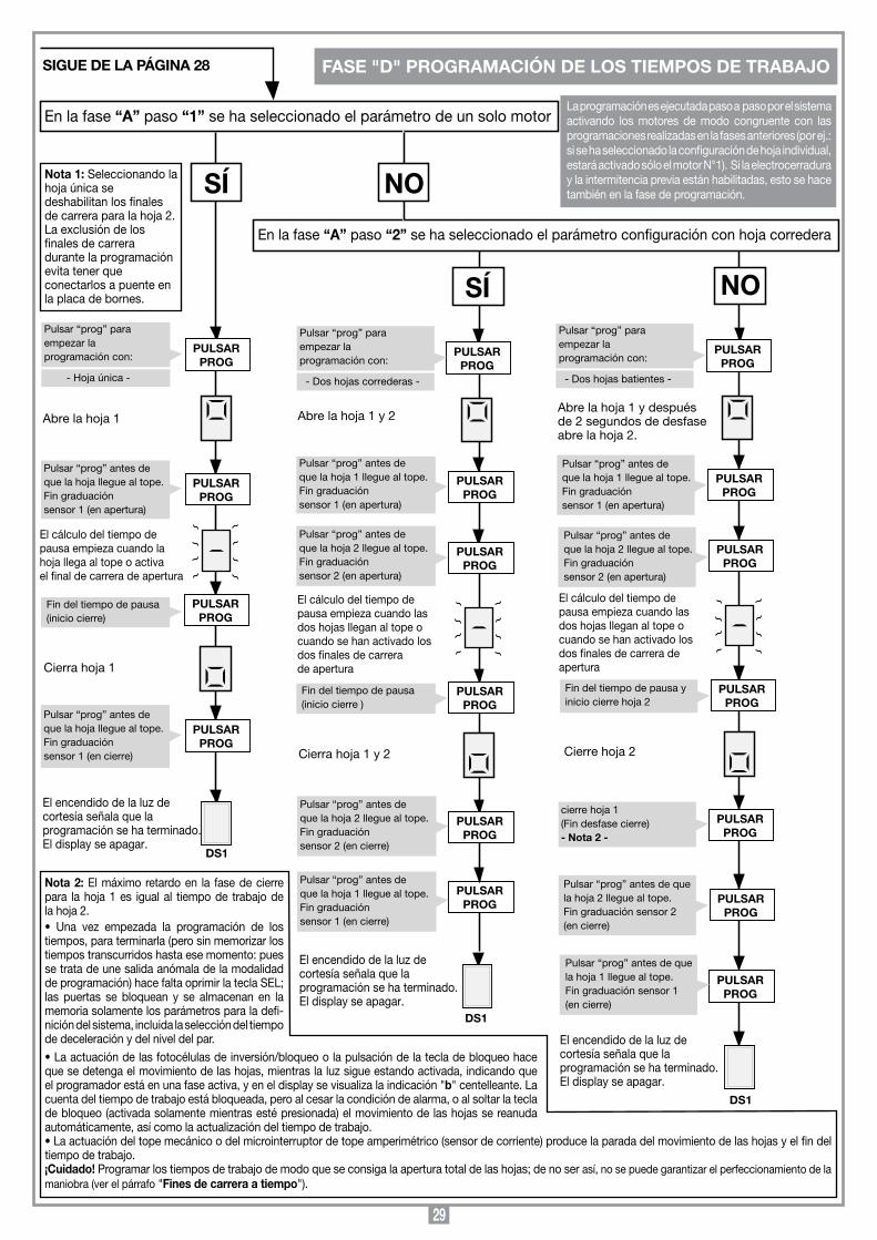
29
Pulsar “prog” paraempezar la programación con:
En la fase “A” paso “1” se ha seleccionado el parámetro de un solo motor
SÍ
Abre la hoja 1
Fin del tiempo de pausa (inicio cierre)
SÍ NO
Pulsar “prog” antes de que la hoja llegue al tope. Fin graduaciónsensor 1 (en apertura)
El cálculo del tiempo de pausa empieza cuando lahoja llega al tope o activa el final de carrera de apertura
Cierra hoja 1
PULSAR PROG
Abre la hoja 1 y 2
Cierra hoja 1 y 2
PULSAR PROG
El encendido de la luz de cortesía señala que la programación se ha terminado.El display se apagar.
PULSAR PROG
Abre la hoja 1 y después de 2 segundos de desfase abre la hoja 2.
PULSAR PROG
Pulsar “prog” antes de que la hoja 2 llegue al tope. Fin graduaciónsensor 2 (en apertura)
El cálculo del tiempo de pausa empieza cuando las dos hojas llegan al tope o cuando se han activado losdos finales de carrera deapertura
PULSAR PROG
PULSAR PROG
El encendido de la luz de cortesía señala que la programación se ha terminado.El display se apagar.
PULSAR PROG
DS1
En la fase “A” paso “2” se ha seleccionado el parámetro configuración con hoja corredera
PULSAR PROG
PULSAR PROG
PULSAR PROG
Pulsar “prog” antes de que la hoja llegue al tope. Fin graduaciónsensor 1 (en cierre)
PULSAR PROG
El encendido de la luz de cortesía señala que la programación se ha terminado.El display se apagar.
PULSAR PROG
PULSAR PROG
PULSAR PROG
DS1
PULSAR PROG
Pulsar “prog” antes de que la hoja 1 llegue al tope. Fin graduaciónsensor 1 (en apertura)
Pulsar “prog” antes de que la hoja 2 llegue al tope. Fin graduaciónsensor 2 (en apertura)
Fin del tiempo de pausa (inicio cierre )
Pulsar “prog” antes de que la hoja 2 llegue al tope. Fin graduaciónsensor 2 (en cierre)
Pulsar “prog” antes de que la hoja 1 llegue al tope. Fin graduaciónsensor 1 (en cierre)
PULSAR PROG
Pulsar “prog” antes de que la hoja 1 llegue al tope. Fin graduaciónsensor 1 (en apertura)
Fin del tiempo de pausa yinicio cierre hoja 2
Cierre hoja 2
PULSAR PROG
cierre hoja 1(Fin desfase cierre)- Nota 2 -
Pulsar “prog” antes de que la hoja 1 llegue al tope.Fin graduación sensor 1(en cierre)
Pulsar “prog” antes de que la hoja 2 llegue al tope.Fin graduación sensor 2(en cierre)
DS1
Nota 1: Seleccionando la hoja única se deshabilitan los finales de carrera para la hoja 2. La exclusión de los finales de carrera durante la programación evita tener que conectarlos a puente en la placa de bornes.
NO
- Hoja única -
Pulsar “prog” paraempezar la programación con:
- Dos hojas correderas -
El cálculo del tiempo depausa empieza cuando las dos hojas llegan al tope o cuando se han activado los dos finales de carrera de apertura
Pulsar “prog” paraempezar la programación con:
- Dos hojas batientes -
SIGUE DE LA PÁGINA 28 FASE "D" PROGRAMACIÓN DE LOS TIEMPOS DE TRABAJO
La programación es ejecutada paso a paso por el sistema activando los motores de modo congruente con las programaciones realizadas en la fases anteriores (por ej.: si se ha seleccionado la configuración de hoja individual, estará activado sólo el motor N°1). Si la electrocerradura y la intermitencia previa están habilitadas, esto se hace también en la fase de programación.
Nota 2: El máximo retardo en la fase de cierre para la hoja 1 es igual al tiempo de trabajo de la hoja 2. • Una vez empezada la programación de lostiempos, para terminarla (pero sin memorizar los tiempos transcurridos hasta ese momento: pues se trata de une salida anómala de la modalidad de programación) hace falta oprimir la tecla SEL; las puertas se bloquean y se almacenan en la memoria solamente los parámetros para la defi-nición del sistema, incluida la selección del tiempo de deceleración y del nivel del par.•Laactuacióndelasfotocélulasdeinversión/bloqueoolapulsacióndelatecladebloqueohaceque se detenga el movimiento de las hojas, mientras la luz sigue estando activada, indicando que el programador está en una fase activa, y en el display se visualiza la indicación "b" centelleante. La cuenta del tiempo de trabajo está bloqueada, pero al cesar la condición de alarma, o al soltar la tecla de bloqueo (activada solamente mientras esté presionada) el movimiento de las hojas se reanuda automáticamente, así como la actualización del tiempo de trabajo. •Laactuacióndeltopemecánicoodelmicrointerruptordetopeamperimétrico(sensordecorriente)producelaparadadelmovimientodelashojasyelfindeltiempo de trabajo. ¡Cuidado! Programar los tiempos de trabajo de modo que se consiga la apertura total de las hojas; de no ser así, no se puede garantizar el perfeccionamiento de la maniobra (ver el párrafo "Fines de carrera a tiempo").
30
1) AutomáticaSe selecciona habilitando el cierre posterior automático (fase "6" de la programación, número "6" fijo). A partir de la condición de puerta totalmente cerrada, el mando de aper-tura empieza un ciclo completo de funcionamiento, que termina con el cierre automático y el apagado temporizado de la luz de servicio. El cierre automático posterior se pone en marcha con un retardo igual al tiempo de pausa programado, a partir del final de la maniobra de apertura o bien del instante en que han actuado las fotocélulas por última vez durante el tiempo de pausa (la actuación de las fotocélulas produce un reset del tiempo de pausa). Durante el tiempo de pausa, en el display se pone centelleante el símbolo ; la pulsación de la tecla de bloqueo durante el tiempo de pausa impide el cierre automático posterior y por consiguiente el bloqueo de la intermitencia en el display. La actuación de los fines de carrera mecánicos o de los microinterruptores de tope amperimétricos conlleva el bloqueo de la hoja. El indicador luminoso queda encendido cuando la puerta no está totalmente cerrada.Nota: la luz de servicio se enciende por cada mando de movimiento dado al sistema, tanto vía cable como vía radio; la actuación de las fotocélulas durante la operación de cierre no surte efecto en la temporización de la luz de servicio.
2) Semi-automáticaSe selecciona deshabilitando el cierre posterior automático (fase "6" de la progra-mación, número "6" centelleante).El ciclo de funcionamiento se gobierna por mandos separados de apertura y cierre. Llegado en la posición de apertura total el sistema aguarda un mando de cierre vía radio o mediante la tecla para finalizar el ciclo. La actuación del fin de carrera de apertura causa el bloqueo de la hoja, y el final de la maniobra de apertura, la luz ama-rilla se apaga al agotarse el tiempo prefijado. El indicador luminoso queda encendido cuando la puerta no está totalmente cerrada.
APERTURA LIMITADASe realiza para la hoja 1; si se ha configurado el sistema como doble hoja, se consigue la apertura completa de la hoja 1; si se ha configurado el sistema como hoja individual, se consigue la apertura parcial de la hoja 1 (aproximadamente 1/3 de su carrera). Es posible realizar el mando sólo con las hojas totalmente cerradas; durante la apertura limitada, si se activa de nuevo el mando "TAL", la hoja 1 se bloquea y se cierra al mando sucesivo. Después de lo cual no se realiza al mando hasta el cierre total.
LUZ DE SERVICIO / SALIDA CH2 RADIOLos bornes "7" y "8" corresponden a los contactos C-NA de un relé; éste se podrá activar con la modalidad "luz de servicio" (contacto cerrado) por un tiempo igual al que se ha programado o bien directamente por el segundo canal de radio, seleccionable en la decodificación integrada en la centralita (puente "J1"). Los bornes "7" y "8" sólo suministran un contacto puro, y no suministran tensión al exterior; esto significa que para utilizar la luz de servicio es necesario alimentar el circuito por separado, y emplear el contacto como simple interruptor.
¡Cuidado! En la tarjeta del programador no está presente la tensión de 230Vac: sólo está la baja tensión. Para la conformidad con la normativa sobre la seguridad eléctra, que dispone determinados aislamientos entre las pistas de alta tensión (230 Vac) y baja tensión (24V ac) no es posible conectar los bornes 7 y 8 directamente a un circuito donde esté aplicada una tensión de 230 Vac. La tensión máxima consentido está 30 Vac/dc.
MODALIDAD MANUALSe puede utilizar para desplazar las hojas en la fase de cierre (o apertura) bajo el control directo del operador; en esta modalidad los dispositivos de seguridad FTC_I, FTC_S y TB actúan sólo mientras están en la condición de alarma. El objetivo es el de facilitar la maniobra de instalación y tener las hojas totalmente cerradas antes de proceder a la programación del sistema. En esta modalidad el LED "L3" (marcado con "UPL") está encendido. La modalidad "manual" se puede accionar también en el funcionamiento con batería; los motores están alimentados con la tensión máxima (velocidad de régimen) independiente-mente de la habilitación o menos de la deceleración. Los dispositivos de seguridad FTC_I (sólo en la fase de cierre, con independencia de la selección al paso "C" de la definición de los parámetros de sistema) y FTC_S son gobernados por el programador, así como los microinterruptores de tope y los sensores de corriente.
• Maniobra de cierreSe consigue manteniendo oprimido la tecla "SEL". El movimiento de cierre se bloquea debido a que:- se ha soltado la tecla "SEL" (se sale de la modalidad manual);- activación de la tecla de bloqueo "TB": para restablecer el movimiento de cierre es
necesario soltar la tecla "SEL" y volver a oprimirlo;- activación del microinterruptor de tope en fase de cierre: la presión del tecla "SEL" no
produce el cierre, sino simplemente el encendido de la luz de servicio.
• Maniobra de aperturaSe consigue manteniendo oprimido la tecla "SEL" y pulsando inmediatamente después la tecla "PROG".El movimiento de apertura se bloquea debido a que:- se han soltado ambas teclas (se sale de la modalidad manual);- activación de la tecla de bloqueo "TB": para restablecer el movimiento de apertura es
necesario soltar ambas teclas y volver a oprimirlas;- activación del microinterruptor de tope en fase de apertura.
• InversióndelmovimientoSi se está en la fase de cierre: para pasar a la maniobra de apertura, oprimir la tecla "PROG"Si se está en la fase de apertura: para pasar a la maniobra de cierre: soltar la tecla "PROG"
• LuzdeservicioLa luz está encendida durante toda la modalidad manual; también se enciende cuando se trata de enviar el mando, pero el microinterruptor de tope impide su ejecución.
ACTUALIZACIÓN DE LOS SENSORES DE CORRIENTELa detección de la corriente absorbida por los motores se hace para poder compensar las pequeñas variaciones eventuales debidas a condiciones ambientales; cuando ocurre esto, en el display comparece una indicación adicional, constituida por un segmento centelleante (tanto más rápidamente cuanto más grande es la compensación que se está actuando). El segmento estará en el lado izquierdo del display para el sensor 1 y en el lado derecho del display para el sensor 2 (ver "Indicaciones del display" en página 27). Cada vez que se bloquea el movimiento, incluyendo la maniobra de inversión, la compensación se pone a cero y se vuelve a computar para tener una actualización continua.
INDICACIONES DE ALARMA1) Parámetros erróneos cargados de EEPROMEn el display centellea la letra y el sistema está bloqueado. La única posibilidad es la de volver a entrar en la modalidad de programación para volver a programar el sistema. Al repetir esta operación, si se vuelve a tener el mismo inconveniente, el problema concierne a la EEPROM (no se puede almacenar en la memoria debida-mente). Cortar la alimentación del sistema, y después de unos segundos volver a encenderlo, repitiendo el procedimiento de programación.
2) Fines de carrera de apertura/cierre activados al mismo tiempo.En el display aparece la letra y el sistema está bloqueado. La lámpara está activada durante unos tres segundos, con un plazo de repetición de seis segundos, y sigue centelleando. Cortar la alimentación del sistema y comprobar el buen estado de los fines de carrera, luego volver a suministrar alimentación al sistema.
FINES DE CARRERA A TIEMPOLa gestión de los tiempos de funcionamiento permite controlar la posición de las hojas.A falta de fluido eléctrico el programador, a no ser que no esté activado uno de los dos microinterruptores de tope, pierde la memoria de la posición de las puertas, que se consideran como "totalmente carradas", para permitir la maniobra de apertura.La gestión de los tiempos de trabajo garantiza que la maniobra de cierre posterior está completa. Para repetidas maniobras de inversión, con la consiguiente parada del movimiento y el arranque lento, se podría tener un erróneo control de los tiempos, y la falta de la deceleración antes de alcanzar el tope. El funcionamiento correcto se restablece al acto de realizar la maniobra sucesiva.
Es posible accionar a distancia el motor por medio del emisor: está disponible la función de mando secuencial "apertura-bloqueo-cierre-bloqueo" o bien "apertura-cierre" (seleccionable), que se realiza indistintamente con uno cualquiera de los canales disponibles. Si en la determinación de los parámetros del sistema se ha seleccionado el número "3" centelleante, se tiene a disposición otro canal con un contacto de salida C-NA (bornes 7, 8).
Módulo de memoriaExtraíble, dotado de memoria no volátil de tipo EEPROM, lleva los códigos de los trans-misores y permite almacenar en la memoria 300 códigos (300 teclas de canales). Los códigos permanecen en el módulo de memoria incluso a falta de fluido eléctrico.
Antes de proceder a la primera memorización, hace falta borrar totalmente la memoria.
¡Cuidado! Al tener que sustituir la tarjeta electrónica debido a alguna avería,
el módulo de memoria se puede sacar e introducir en la nueva tarjeta cuidando su orientación según lo que está indicado en la fig. 1 dett. A.
GESTIÓN DE LOS CÓDIGOS DE LOS TRANSMISORESIndicaciones LED "L2" (fig.1): luz centelleante rápidamente: borrado de un códigoluz centelleante lentamente: almacenamiento de un códigoluz fija: memoria enteramente ocupada.
Almacenamiento de un canal (fig.1):1. Presionar la tecla "P3" MEMO y mantenerlo pulsado: el LED "L2" se pone a
centellear lentamente.2. Activar simultáneamente el transmisor en el canal a memorizar.3. Mantener presionado la tecla "P3" MEMO hasta que el LED "L2" vuelve a estar
centelleante.
MODALIDAD DE FUNCIONAMIENTO
MANDO VÍA RADIO S449
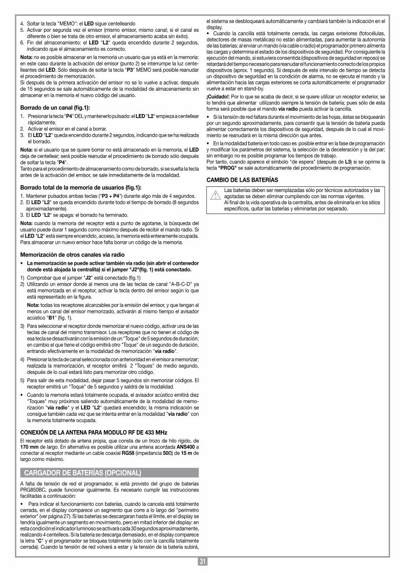
31
4. Soltar la tecla "MEMO": el LED sigue centelleando5. Activar por segunda vez el emisor (mismo emisor, mismo canal; si el canal es
diferente o bien se trata de otro emisor, el almacenamiento acaba sin éxito).6. Fin del almacenamiento: el LED "L2" queda encendido durante 2 segundos,
indicando que el almacenamiento es correcto.
Nota: no es posible almacenar en la memoria un usuario que ya está en la memoria: en este caso durante la activación del emisor (punto 2) se interrumpe la luz cente-lleantes del LED. Sólo después de soltar la tecla "P3" MEMO será posible reanudar el procedimiento de memorización. Si después de la primera activación del emisor no se lo vuelve a activar, después de 15 segundos se sale automáticamente de la modalidad de almacenamiento sin almacenar en la memoria el nuevo código del usuario.
Borrado de un canal (fig.1):1. Presionar la tecla "P4" DEL y mantenerlo pulsado: el LED "L2" empieza a centellear
rápidamente.2. Activar el emisor en el canal a borrar.3. El LED "L2" queda encendido durante 2 segundos, indicando que se ha realizada
el borrado.
Nota: si el usuario que se quiere borrar no está almacenado en la memoria, el LED deja de centellear; será posible reanudar el procedimiento de borrado sólo después de soltar la tecla "P4".Tanto para el procedimiento de almacenamiento como de borrado, si se suelta la tecla antes de la activación del emisor, se sale inmediatamente de la modalidad.
Borrado total de la memoria de usuarios (fig.1):1. Mantener pulsados ambas teclas ("P3 + P4") durante algo más de 4 segundos.2. El LED "L2" se queda encendido durante todo el tiempo de borrado (8 segundos
aproximadamente).3. El LED "L2" se apaga: el borrado ha terminado.
Nota: cuando la memoria del receptor está a punto de agotarse, la búsqueda del usuario puede durar 1 segundo como máximo después de recibir el mando radio. Si el LED "L2" está siempre encendido, acceso, la memoria está enteramente ocupada. Para almacenar un nuevo emisor hace falta borrar un código de la memoria.
Memorización de otros canales vía radio • La memorización se puede activar también vía radio (sin abrir el contenedor
donde está alojada la centralita) si el jumper "J2"(fig. 1) está conectado.
1) Comprobar que el jumper "J2" está conectado (fig.1)2) Utilizando un emisor donde al menos una de las teclas de canal "A-B-C-D" ya
está memorizada en el receptor, activar la tecla dentro del emisor según lo que está representado en la figura.
Nota: todas los receptores alcanzables por la emisión del emisor, y que tengan al menos un canal del emisor memorizado, activarán al mismo tiempo el avisador acústico "B1" (fig. 1).
3) Para seleccionar el receptor donde memorizar el nuevo código, activar una de las teclas de canal del mismo transmisor. Los receptores que no tienen el código de esa tecla se desactivarán con la emisión de un "Toque" de 5 segundos de duración; en cambio el que tiene el código emitirá otro "Toque" de un segundo de duración, entrando efectivamente en la modalidad de memorización "vía radio".
4) Presionar la tecla de canal seleccionada con anterioridad en el emisor a memorizar; realizada la memorización, el receptor emitirá 2 "Toques" de medio segundo, después de lo cual estará listo para memorizar otro código.
5) Para salir de esta modalidad, dejar pasar 5 segundos sin memorizar códigos. El receptor emitirá un "Toque" de 5 segundos y saldrá de la modalidad.
• Cuandolamemoriaestarátotalmenteocupada,elavisadoracústicoemitirádiez"Toques" muy próximos saliendo automáticamente de la modalidad de memo-rización "vía radio" y el LED "L2" quedará encendido; la misma indicación se consigue también cada vez que se intenta entrar en la modalidad "vía radio" con la memoria totalmente ocupada.
CONExIÓN DE LA ANTENA PARA MODULO RF DE 433 MHzEl receptor está dotado de antena propia, que consta de un trozo de hilo rígido, de 170 mm de largo. En alternativa es posible utilizar una antena acordada ANS400 a conectar al receptor mediante un cable coaxial RG58 (impedancia 50Ω) de 15 m de largo como máximo.
A falta de tensión de red el programador, si está provisto del grupo de baterías PRG850BC, puede funcionar igualmente. Es necesario cumplir las instrucciones facilitadas a continuación:
• Paraindicarelfuncionamientoconbaterías,cuandolacancelaestátotalmentecerrada, en el display comparece un segmento que corre a lo largo del "perímetro exterior" (ver página 27). Si las baterías se descargaran hasta el límite, en el display se tendría igualmente un segmento en movimiento, pero en mitad inferior del display: en esta condición el indicador luminoso se activará cada 30 segundos aproximadamente, realizando 4 centelleos. Si la batería se descarga demasiado, en el display comparece la letra "C" y el programador se bloquea totalmente (sólo con la cancilla totalmente cerrada). Cuando la tensión de red volverá a estar y la tensión de la batería subirá,
el sistema se desbloqueará automáticamente y cambiará también la indicación en el display.• Cuando lacancilla está totalmentecerrada, lascargasexteriores (fotocélulas,detectores de masas metálicas) no están alimentadas, para aumentar la autonomía de las baterías; al enviar un mando (vía cable o radio) el programador primero alimenta las cargas y determina el estado de los dispositivos de seguridad. Por consiguiente la ejecución del mando, si estuviera consentida (dispositivos de seguridad en reposo) se retardará del tiempo necesario para reanudar el funcionamiento correcto de los propios dispositivos (aprox. 1 segundo). Si después de este intervalo de tiempo se detecta un dispositivo de seguridad en la condición de alarma, no se ejecuta el mando y la alimentación hacia las cargas exteriores se corta automáticamente: el programador vuelve a estar en stand-by.
¡Cuidado!: Por lo que se acaba de decir, si se quiere utilizar un receptor exterior, se lo tendrá que alimentar utilizando siempre la tensión de batería; pues sólo de esta forma será posible que el mando vía radio pueda activar la cancilla.
• Silatensiónderedfaltaraduranteelmovimientodelashojas,éstassebloquearánpor un segundo aproximadamente, para consentir que la tensión de batería pueda alimentar correctamente los dispositivos de seguridad, después de lo cual el movi-miento se reanudará en la misma dirección que antes.
• Enlamodalidadbateríaentodocasoesposibleentrarenlafasedeprogramacióny modificar los parámetros del sistema, la selección de la deceleración y la del par; sin embargo no es posible programar los tiempos de trabajo. Por tanto, cuando aparece el símbolo "de espera" (después de L3) si se oprime la tecla "PROG" se sale automáticamente del procedimiento de programación.
CAMBIO DE LAS BATERÍAS
Las baterías deben ser reemplazadas sólo por técnicos autorizados y las agotadas se deben eliminar cumpliendo con las normas vigentes.Al final de la vida operativa de la centralita, antes de eliminarla en los sitios específicos, quitar las baterías y eliminarlas por separado.
CARGADOR DE BATERÍAS (OPCIONAL)

32
NOTES

33
NOTES

34
NOTES
35
The CE conformity declaration for Cardin products is available in original language from the site www.cardin.it under the section "Standards and Certification".Les déclarations de conformité CE des produits Cardin sont disponibles dans la langue originale sur le site www.cardin.it dans la section "normes et certificats".Die CE-Konformitätserklärungen für die Cardin-Produkte stehen in der Originalsprache auf der Homepage www.cardin.it im Bereich "Normen und Zertifizierung" zur Verfügung.Las declaraciones de conformidad CE de los productos Cardin se encuentran disponibles en el idioma original en el sitio www.cardin.it en la sección "normas y certificaciones".
CARDIN ELETTRONICA spa Via Raffaello, 36- 31020 San Vendemiano (TV) ItalyTel: +39/0438.404011-401818Fax: +39/0438.401831email (Italy): [email protected] (Europe): [email protected]: www.cardin.it
PRG 852 05-07-2002DCE031
Il Costruttore: CARDIN ELETTRONICA S.p.A. DICHIARA CHE L'AppARECCHIAtuRA DEstInAtA AD EssERE InsERItA In mACCHInE E non funzIonAntE In moDo InDIpEnDEntE:
Nome dell'apparato Centralina elettronica PRG852 per 2 motori 24 VdcTipo di apparato Centralina elettronica Modello PRG8522CC, PRG85220C, PRG85221C
Dichiara inoltre di essere in possesso dei seguenti rapporti di prova rilasciati dal "Competent Body" PRIMA RICERCA & SVILUPPO:- EMC.TR.00.734 (23.10.00) - certificato di conformità CE n° 00.204- SAF.TR.00.735 (19.12.01) - certificato di conformità CE n° 01.409- SAF.TR.02.170 (03.07.02) - certificato di conformità CE n° 02.140
è in conformità a quanto previsto dalle seguenti direttive comunitarie:- Direttiva 89/336/EEC (Compatibilità Elettromagnetica)- Direttiva 73/23/EEC (Bassa Tensione)
e che sono state applicate le seguenti norme e/o specifiche tecniche:- ETS300683 : 1997- EN60335-1 : 1994 + A11:1995 + A1 : 1996 + A12: 1996 + A13: 1998 + A14: 1998 + A15: 2000
San Vendemiano il 05/07/2002 Ing. M. Terruso
(Resp. Certif. & Omologazioni)
x x x x x x x x x x x x x x x x x x x x x x x x x x x x x x x x x x x x x x x x x x x x x x x x x x x x x x x x x x
x x x x x x x x x x x x x x x x x x x x x x x x x x x x x x x x x x x x x x x x x x x x x x x x x x x x x x x x x x
x x x x x x x x x x x x x x x x x x x x x x x x x x x x x x x x x x x x x x x x x x x x x x x x x x x x x x x x x x
x x x x x x x x x x x x x x x x x x x x x x x x x x x x x x x x x x x x x x x x x x x x x x x x x x x x x x x x x x
x x x x x x x x x x x x x x x x x x x x x x x x x x x x x x x x x x x x x x x x x x x x x x x x x x x x x x x x x x
x x x x x x x x x x x x x x x x x x x x x x x x x x x x x x x x x x x x x x x x x x x x x x x x x x x x x x x x x x
x x x x x x x x x x x x x x x x x x x x x x x x x x x x x x x x x x x x x x x x x x x x x x x x x x x x x x x x x x
x x x x x x x x x x x x x x x x x x x x x x x x x x x x x x x x x x x x x x x x x x x x x x x x x x x x x x x x x
x x x x x x x x x x x x x x x x x x x x x x x x x x x x x x x x x x x x x x x x x x x x x x x x x x x x x x x x x x
x x x x x x x x x x x x x x x x x x x x x x x x x x x x x x x x x x x x x x x x x x x x x x x x x x x x x x x x x x
x x x x x x x x x x x x x x x x x x x x x x x x x x x x x x x x x x x x x x x x x x x x x x x x x x x x x x x x x x
x x x x x x x x x x x x x x x x x x x x x x x x x x x x x x x x x x x x x x x x x x x x x x x x x x x x x x x x x x
x x x x x x x x x x x x x x x x x x x x x x x x x x x x x x x x x x x x x x x x x x x x x x x x x x x x x x x x x x
x x x x x x x x x x x x x x x x x x x x x x x x x x x x x x x x x x x x x x x x x x x x x x x x x x x x x x x x x x
x x x x x x x x x x x x x x x x x x x x x x x x x x x x x x x x x x x x x x x x x x x x x x x x x x x x x x x x x
x x x x x x x x x x x x x x x x x x x x x x x x x x x x x x x x x x x x x x x x x x x x x x x x x x x x x x x x x x
x x x x x x x x x x x x x x x x x x x x x x x x x x x x x x x x x x x x x x x x x x x x x x x x x x x x x x x x x x
x x x x x x x x x x x x x x x x x x x x x x x x x x x x x x x x x x x x x x x x x x x x x x x x x x x x x x x x x x
x x x x x x x x x x x x x x x x x x x x x x x x x x x x x x x x x x x x x x x x x x x x x x x x x x x x x x x x x
x x x x x x x x x x x x x x x x x x x x x x x x x x x x x x x x x x x x x x x x x x x x x x x x x x x x x x x x x
x x x x x x x x x x x x x x x x x x x x x x x x x x x x x x x x x x x x x x x x x x x x x x x x x x x x x x x x x x
x x x x x x x x x x x x x x x x x x x x x x x x x x x x x x x x x x x x x x x x x x x x x x x x x x x x x x x x x x
x x x x x x x x x x x x x x x x x x x x x x x x x x x x x x x x x x x x x x x x x x x x x x x x x x x x x x x x x x
x x x x x x x x x x x x x x x x x x x x x x x x x x x x x x x x x x x x x x x x x x x x x x x x x x x x x x x x x
Dichiarazione di Conformità CE(Dichiarazione del costruttore)
MODELLO DATACODICE SERIE
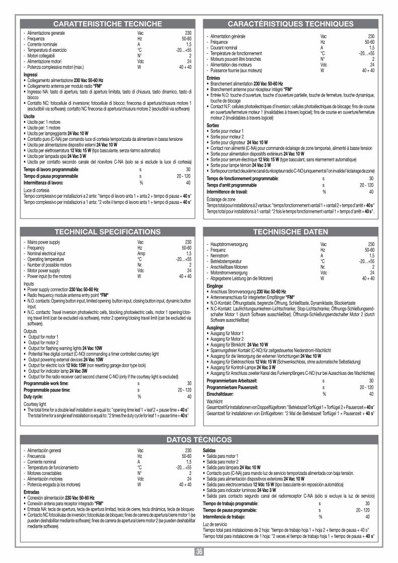
36
TECHNICAL SPECIFICATIONS
DATOS TÉCNICOS
TECHNISCHE DATEN
CARATTERISTICHE TECNICHE CARACTÉRISTIQUES TECHNIQUES
- Mains power supply Vac 230- Frequency Hz 50-60- Nominal electrical input Amp 1,5- Operating temperature °C -20…+55- Number of possible motors Nr. 2- Motor power supply Vdc 24- Power input (to the motors) W 40 + 40Inputs• Powersupplyconnection230 Vac 50-60 Hz • Radiofrequencymoduleantennaentrypoint"FM" • N.O.contacts:Openingbuttoninput,limitedopeningbuttoninput,closingbuttoninput,dynamicbutton
input. • N.C.contacts:Travelinversionphotoelectriccells,blockingphotoelectriccells,motor1opening/clos-
ing travel limit (can be excluded via software), motor 2 opening/closing travel limit (can be excluded via software).
Outputs• Outputformotor1• Outputformotor2• Outputforflashingwarninglights24 Vac 10W• Potentialfreedigitalcontact(C-NO)commandingatimercontrolledcourtesylight• Outputpoweringexternaldevices24 Vac 10W• Outputforelectriclock12 Vdc 15W (non resetting garage door type lock)• Outputforindicatorlamp 24 Vac 3W• OutputfortheradioreceivercardsecondchannelC-NO(onlyifthecourtesylightisexcluded)Programmable work time: s 30Programmable pause time: s 20 - 120Duty cycle: % 40Courtesy light • Thetotaltimeforadoubleleafinstallationisequalto:"openingtimeleaf1+leaf2+pausetime+40 s"
The total time for a single leaf installation is equal to: "2 times the duty cycle for leaf 1 + pause time + 40 s"
- Alimentation générale Vac 230 - Fréquence Hz 50-60 - Courant nominal A 1,5- Température de fonctionnement °C -20…+55- Moteurs pouvant être branchés N° 2- Alimentation des moteurs Vdc 24- Puissance fournie (aux moteurs) W 40 + 40Entrées• Branchementalimentation230 Vac 50-60 Hz • Branchementantennepourrécepteurintégré"FM"• EntréeN.O:touched'ouverture,touched'ouverturepartielle,touchedefermeture,touchedynamique,
touche de blocage• ContactN.F:cellulesphotoélectriquesd'inversion;cellulesphotoélectriquesdeblocage;finsdecourse
en ouverture/fermeture moteur 1 (invalidables à travers logiciel); fins de course en ouverture/fermeture moteur 2 (invalidables à travers logiciel)
Sorties• Sortiepourmoteur1• Sortiepourmoteur2• Sortiepourclignoteur24 Vac 10 W • Contactnonalimenté(C-NA)pourcommandeéclairagedezonetemporisé,alimentéàbassetension• Sortiepouralimentationdispositifsextérieurs24 Vac 10 W• Sortiepourserrureélectrique12 Vdc 15 W (type basculant, sans réarmement automatique)• Sortiepourlampetémoin24 Vac 3 W• SortiepourcontactdeuxièmecanaldurécepteurradioC-NO(uniquementsil'oninvalidel'éclairagedezone)Temps de fonctionnement programmable: s 30Temps d'arrêt programmable s 20 - 120Intermittence de travail: % 40Éclairage de zone Temps total pour installations à 2 vantaux: "temps fonctionnement vantail 1 + vantail 2 + temps d'arrêt + 40 s"Temps total pour installations à 1 vantail: "2 fois le temps fonctionnement vantail 1 + temps d'arrêt + 40 s".
- Alimentazione generale Vac 230 - Frequenza Hz 50-60 - Corrente nominale A 1,5- Temperatura di esercizio °C -20…+55- Motori collegabili N° 2- Alimentazione motori Vdc 24- Potenza complessiva motori (max.) W 40 + 40Ingressi• Collegamentoalimentazione230 Vac 50-60 Hz • Collegamentoantennapermoduloradio"FM"• IngressoNA: tastodiapertura, tastodiapertura limitata, tastodichiusura, tastodinamico, tastodi
blocco• ContattoNC:fotocelluledi inversione;fotocellulediblocco;finecorsadiapertura/chiusuramotore1
(escludibili via software); contatto NC finecorsa di apertura/chiusura motore 2 (escludibili via software) Uscite• Usciteper:1motore• Usciteper:1motore• Uscitaperlampeggiante24 Vac 10 W • Contattopuro(C-NA)percomandolucedicortesiatemporizzatadaalimentareinbassatensione• Uscitaperalimentazionedispositiviesterni24 Vac 10 W• Uscitaperelettroserratura12 Vdc 15 W (tipo basculante, senza riarmo automatico)• Uscitaperlampadaspia24 Vac 3 W• Uscita per contatto secondo canale del ricevitore C-NA (solo se si esclude la luce di cortesia)Tempo di lavoro programmabile: s 30Tempo di pausa programmabile s 20 - 120Intermittenza di lavoro: % 40Luce di cortesia Tempo complessivo per installazioni a 2 ante: "tempo di lavoro anta 1 + anta 2 + tempo di pausa + 40 s"Tempo complessivo per installazioni a 1 anta: "2 volte il tempo di lavoro anta 1 + tempo di pausa + 40 s"
- Hauptstromversorgung Vac 230 - Frequenz Hz 50-60 - Nennstrom A 1,5- Betriebstemperatur °C -20…+55- Anschließbare Motoren Nr. 2- Motorstromversorgung Vdc 24- Abgegebene Leistung (an die Motoren) W 40 + 40Eingänge• AnschlussStromversorgung230 Vac 50-60 Hz • AntennenanschlussfürintegriertenEmpfänger"FM"• N.O-Kontakt:Öffnungstaste,begrenzteÖffnung,Schließtaste,Dynamiktaste,Blockiertaste• N.C-Kontakt:Laufrichtungsumkehren-Lichtschranke;Stop-Lichtschranke;Öffnungs-Schließungsend-
schalter Motor 1 (durch Software ausschließbar). Öffnungs-Schließungsendschalter Motor 2 (durch Software ausschließbar)
Ausgänge• AusgangfürMotor1• AusgangfürMotor2• AusgangfürBlinklicht24 Vac 10 W • SpannungsfreierKontakt(C-NO)fürzeitgesteuertesNiederstrom-Wachlicht• AusgangfürdieVersorgungderexternenVorrichtungen24 Vac 10 W• AusgangfürElektroschloss12 Vdc 15 W (Schwenkschloss, ohne automatische Selbstladung)• AusgangfürKontroll-Lampe24 Vac 3 W• AusgangfürAnschlusszweiterKanaldesFunkempfängersC-NO(nurbeiAusschlussdesWachlichtes)Programmierbare Arbeitszeit: s 30Programmierbare Pausenzeit: s 20 - 120Einschaltdauer: % 40Wachlicht Gesamtzeit für Installationen von Doppelflügeltoren: "Betriebszeit Torflügel 1 + Torflügel 2 + Pausenzeit + 40 s"Gesamtzeit für Installationen von Einflügeltoren: "2 Mal die Betriebszeit Torflügel 1 + Pausenzeit + 40 s"
- Alimentación general Vac 230 - Frecuencia Hz 50-60 - Corriente nominal A 1,5- Temperatura de funcionamiento °C -20…+55- Motores conectables N° 2- Alimentación motores Vdc 24- Potencia erogada (a los motores) W 40 + 40Entradas• Conexiónalimentación230 Vac 50-60 Hz • Conexiónantenaparareceptorintegrado"FM"• EntradaNA:tecladeapertura,tecladeaperturalimitad,tecladecierre,tecladinámica,tecladebloqueo• ContactoNCfotocélulasdeinversión;fotocélulasdebloqueo;finesdecarreradeapertura/cierremotor1(se
pueden deshabilitar mediante software); fines de carrera de apertura/cierre motor 2 (se pueden deshabilitar mediante software).
Salidas• Salidaparamotor1• Salidaparamotor2• Salidaparalámpara24 Vac 10 W • Contactopuro(C-NA)paramandoluzdeserviciotemporizadaalimentadaconbajatensión.• Salidaparaalimentacióndispositivosexteriores24 Vac 10 W• Salidaparaelectrocerradura12 Vdc 15 W (tipo basculante sin reposición automática)• Salidaparaindicadorluminoso24 Vac 3 W• Salida para contacto segundo canal del radiorreceptor C-NA (sólo si excluye la luz de servicio)Tiempo de trabajo programable: s 30Tiempo de pausa programable: s 20 - 120Intermitencia de trabajo: % 40Luz de servicio Tiempo total para instalaciones de 2 hoja: "tiempo de trabajo hoja 1 + hoja 2 + tiempo de pausa + 40 s"Tiempo total para instalaciones de 1 hoja: "2 veces el tiempo de trabajo hoja 1 + tiempo de pausa + 40 s"