MODUL PCI 4 - ortecspa.it
15
1 Catalogo tecnico/2002 Quadri normalizzati di Technical catalogue/2002 bassa tensione Standardized low voltage Switchboards MODUL PCI 4 rtec INDUSTRIALE S.p.A
Transcript of MODUL PCI 4 - ortecspa.it

1
Catalogo tecnico/2002 Quadri normalizzati di Technical catalogue/2002 bassa tensione Standardized low voltage Switchboards
MODUL PCI 4
rtecINDUSTRIALE S.p.A
2
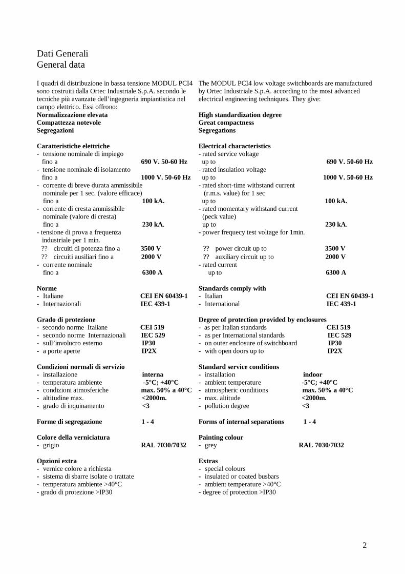
Dati Generali General data I quadri di distribuzione in bassa tensione MODUL PCI4 sono costruiti dalla Ortec Industriale S.p.A. secondo le tecniche più avanzate dell’ingegneria impiantistica nel campo elettrico. Essi offrono: Normalizzazione elevata Compattezza notevole Segregazioni Caratteristiche elettriche - tensione nominale di impiego fino a 690 V. 50-60 Hz - tensione nominale di isolamento fino a 1000 V. 50-60 Hz - corrente di breve durata ammissibile
nominale per 1 sec. (valore efficace) fino a 100 kA.
- corrente di cresta ammissibile nominale (valore di cresta) fino a 230 kA.
- tensione di prova a frequenza industriale per 1 min. ? ? circuiti di potenza fino a 3500 V ? ? circuiti ausiliari fino a 2000 V
- corrente nominale fino a 6300 A
Norme - Italiane CEI EN 60439-1 - Internazionali IEC 439-1 Grado di protezione - secondo norme Italiane CEI 519 - secondo norme Internazionali IEC 529 - sull’involucro esterno IP30 - a porte aperte IP2X Condizioni normali di servizio - installazione interna - temperatura ambiente -5°C; +40°C - condizioni atmosferiche max. 50% a 40°C - altitudine max. <2000m. - grado di inquinamento <3 Forme di segregazione 1 - 4 Colore della verniciatura - grigio RAL 7030/7032 Opzioni extra - vernice colore a richiesta - sistema di sbarre isolate o trattate - temperatura ambiente >40°C - grado di protezione >IP30
The MODUL PCI4 low voltage switchboards are manufactured by Ortec Industriale S.p.A. according to the most advanced electrical engineering techniques. They give: High standardization degree Great compactness Segregations Electrical characteristics - rated service voltage up to 690 V. 50-60 Hz - rated insulation voltage up to 1000 V. 50-60 Hz - rated short-time withstand current (r.m.s. value) for 1 sec up to 100 kA. - rated momentary withstand current
(peck value) up to 230 kA.
- power frequecy test voltage for 1min. ? ? power circuit up to 3500 V ? ? auxiliary circuit up to 2000 V
- rated current up to 6300 A
Standards comply with - Italian CEI EN 60439-1 - International IEC 439-1 Degree of protection provided by enclosures - as per Italian standards CEI 519 - as per International standards IEC 529 - on outer enclosure of switchboard IP30 - with open doors up to IP2X Standard service conditions - installation indoor - ambient temperature -5°C; +40°C - atmospheric conditions max. 50% a 40°C - max. altitude <2000m. - pollution degree <3 Forms of internal separations 1 - 4 Painting colour - grey RAL 7030/7032 Extras - special colours - insulated or coated busbars - ambient temperature >40°C - degree of protection >IP30

3
Caratteristiche costruttive Costructional characteristics
Struttura del quadro
Il quadro MODUL PCI4 è costituito da scomparti ad elementi modulari prefabbricati di tipo imbullonato.
Le celle sono metallicamente segregate le une dalle altre. Il quadro è predisposto per essere facilmente ampliato su entrambi i lati. Ogni scomparto può essere costituito da:
- celle interruttori - celle strumenti - vano sbarre - vano cavi e morsettiere
Il quadro è percorso per tutta la sua lunghezza da una sbarra di rame elettrolitico, con sezione adeguata al livello di cortocircuito, predisposta alle due estremità per il collegamento alla rete di terra. La struttura e le separazioni interne sono realizzate in lamiera zenzimir opportunamente forata e piegata (struttura in lamiera zenzimir spessore di 2,5 mm; separazioni in lamiera zenzimir spessore di 1,5-2 mm). Le portelle esterne, i fianchi ed il tetto sono realizzati con lamiera decapata lucida da 1,5mm
Switchboard Structure The switchboard MODUL PCI4 is panel type, made of bolted prefab modular elements. The cubicle are metal segregated. The switchboard can be easly extended at both sides. Each panel can be made up of:
- circuit breakers cubicle - instruments cubicles - busbars cubicles - cables & terminal boards cubicles
The switchboard is fitted for its whole length with electrolytic copper bars, or ground connection. The structure and separators are made of punched and bent zenzimir plate (structure zenzimir plate thickness 2.5mm; separators zenzimir plate thickness 1.5-2 mm). External doors, sides and top are made with bright pickled sheet iron (thickness 1.5 mm).
4
Caratteristiche costruttive Constructive characteristics
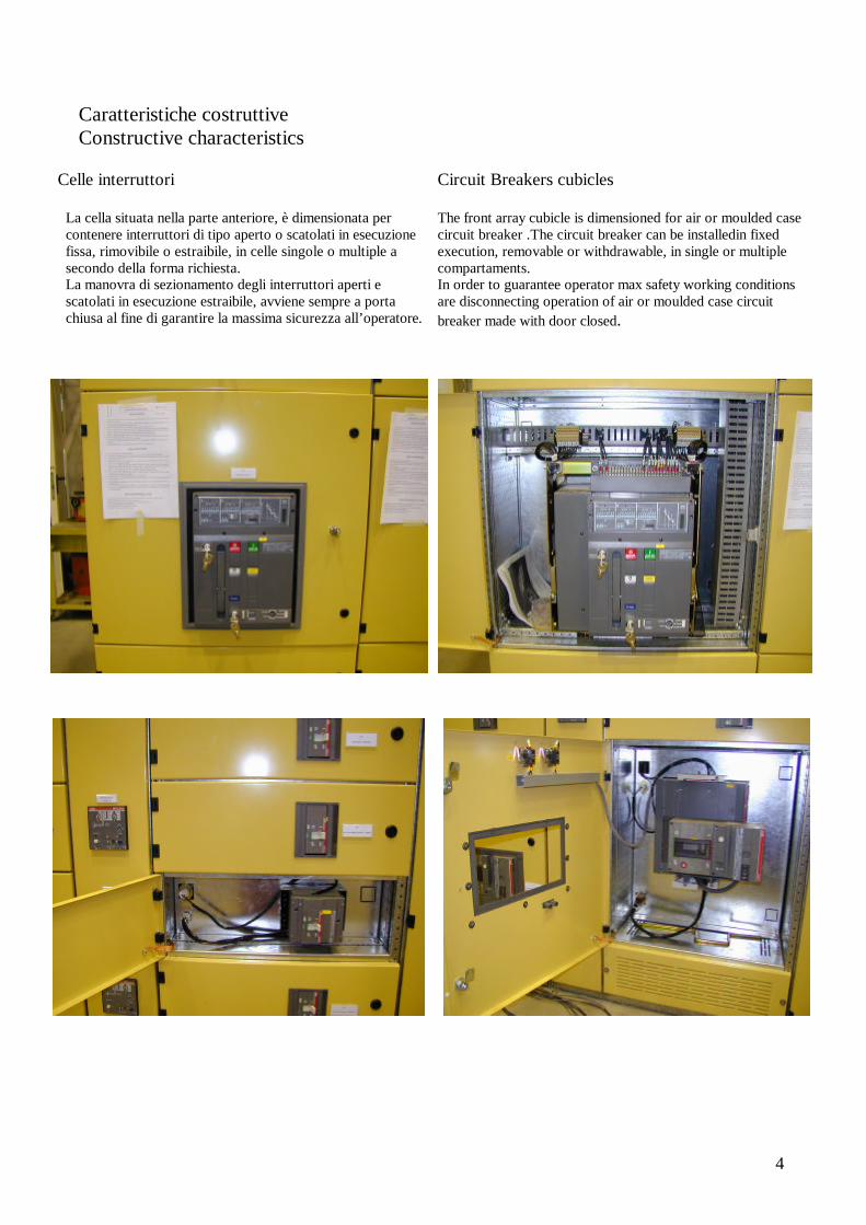
Celle interruttori
La cella situata nella parte anteriore, è dimensionata per contenere interruttori di tipo aperto o scatolati in esecuzione fissa, rimovibile o estraibile, in celle singole o multiple a secondo della forma richiesta. La manovra di sezionamento degli interruttori aperti e scatolati in esecuzione estraibile, avviene sempre a porta chiusa al fine di garantire la massima sicurezza all’operatore.
Circuit Breakers cubicles The front array cubicle is dimensioned for air or moulded case circuit breaker .The circuit breaker can be installedin fixed execution, removable or withdrawable, in single or multiple compartaments. In order to guarantee operator max safety working conditions are disconnecting operation of air or moulded case circuit breaker made with door closed.

5
Caratteristiche costruttive Costructive characteristics Cella strumenti La cella strumenti è normalmente realizzata nella parte superiore dello scomparto, essa è accessibile a mezzo di portella incernierata provvista di serratura ad impronta. Sulla portella sono normalmente montati gli strumenti di misura, i relè di protezione ed i dispositivi di comando e segnalazione, mentre all’ interno trovano collocazione i relè ausiliari, i fusibili di protezione e quanto altro necessario per la protezione e comando del quadro. Per gli interruttori di distribuzione, la cella strumenti può essere realizzata sul laterale destro.
Instruments Cubicle Usually the instruments cubicle is located in the top part of the panel. The access to the cubicle is by hinged door with special key. Usually the measurement and signaling instruments , the protection relays and control devices are mounted on the door. Inside the cubicle are installed the auxiliary relays, the protection fuses and all those devices necessary for switchboard protection or control. For distribution circuit breakers the instruments cubicle can be realized on the right side.
6
Caratteristiche costruttive Constructive characteristics
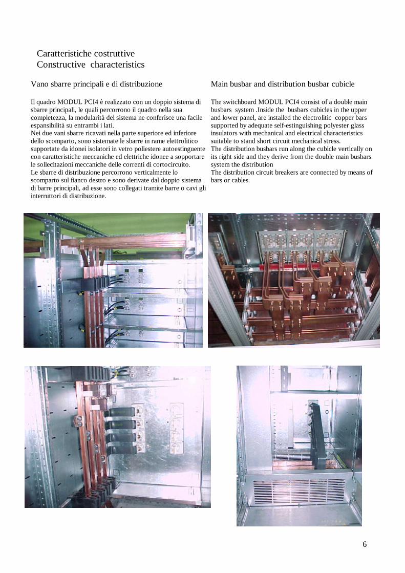
Vano sbarre principali e di distribuzione Il quadro MODUL PCI4 è realizzato con un doppio sistema di sbarre principali, le quali percorrono il quadro nella sua completezza, la modularità del sistema ne conferisce una facile espansibilità su entrambi i lati. Nei due vani sbarre ricavati nella parte superiore ed inferiore dello scomparto, sono sistemate le sbarre in rame elettrolitico supportate da idonei isolatori in vetro poliestere autoestinguente con caratteristiche meccaniche ed elettriche idonee a sopportare le sollecitazioni meccaniche delle correnti di cortocircuito. Le sbarre di distribuzione percorrono verticalmente lo scomparto sul fianco destro e sono derivate dal doppio sistema di barre principali, ad esse sono collegati tramite barre o cavi gli interruttori di distribuzione.
Main busbar and distribution busbar cubicle The switchboard MODUL PCI4 consist of a double main busbars system .Inside the busbars cubicles in the upper and lower panel, are installed the electrolitic copper bars supported by adequate self-estinguishing polyester glass insulators with mechanical and electrical characteristics suitable to stand short circuit mechanical stress. The distribution busbars run along the cubicle vertically on its right side and they derive from the double main busbars system the distribution The distribution circuit breakers are connected by means of bars or cables.
7
Caratteristiche costruttive Constructive characteristics
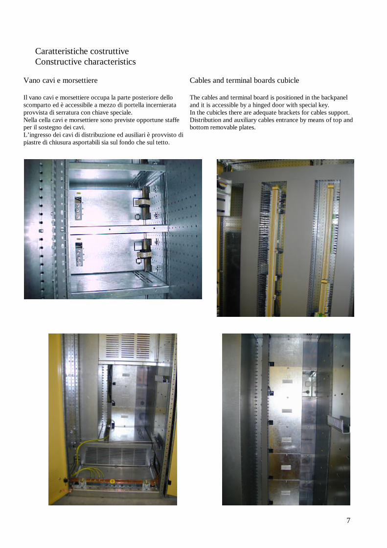
Vano cavi e morsettiere Il vano cavi e morsettiere occupa la parte posteriore dello scomparto ed è accessibile a mezzo di portella incernierata provvista di serratura con chiave speciale. Nella cella cavi e morsettiere sono previste opportune staffe per il sostegno dei cavi. L’ingresso dei cavi di distribuzione ed ausiliari è provvisto di piastre di chiusura asportabili sia sul fondo che sul tetto.
Cables and terminal boards cubicle The cables and terminal board is positioned in the backpanel and it is accessible by a hinged door with special key. In the cubicles there are adequate brackets for cables support. Distribution and auxiliary cables entrance by means of top and bottom removable plates.
8
Caratteristiche costruttive Constructive characteristics Trattamenti superficiali I rivestimenti sono verniciati con sistema elettrolitico su impianto automatico secondo il seguente ciclo: - pre-trattamento di sgrassaggio e fosfatazione a caldo - applicazione di polveri a base di resina epossipoliestere colore standard RAL 7032-7030 - polimerizzazione a forno Lo spessore standard del ciclo normale è di 60 micron
Surfaces Treatment The coverings are electrostatical system painted, on automatic plant; Standards cycle is the following:
- cold and hot phospating treatment: - all structures are painted with epoxi-polyester
resin standard colour RAL 7032-7030 - polymerization in furnace
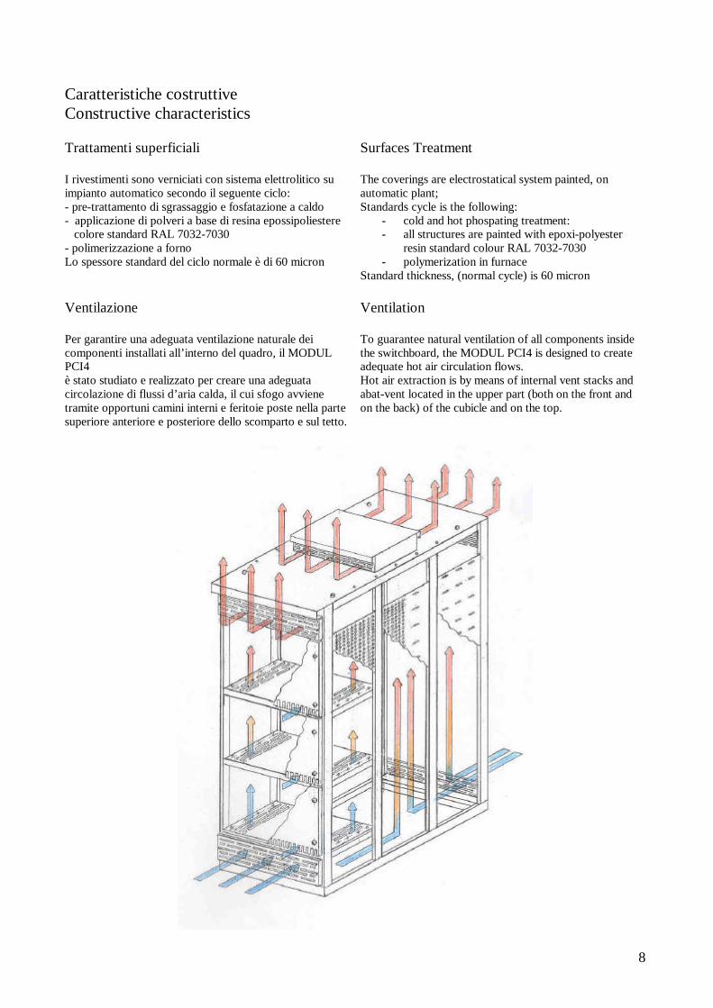
Standard thickness, (normal cycle) is 60 micron Ventilazione Per garantire una adeguata ventilazione naturale dei componenti installati all’interno del quadro, il MODUL PCI4 è stato studiato e realizzato per creare una adeguata circolazione di flussi d’aria calda, il cui sfogo avviene tramite opportuni camini interni e feritoie poste nella parte superiore anteriore e posteriore dello scomparto e sul tetto.
Ventilation To guarantee natural ventilation of all components inside the switchboard, the MODUL PCI4 is designed to create adequate hot air circulation flows. Hot air extraction is by means of internal vent stacks and abat-vent located in the upper part (both on the front and on the back) of the cubicle and on the top.

9
Caratteristiche scomparti base Basic units characteristics Identificazione del tipo di scomparto Unit type identification Interruttori
circuit-breaker ABB-SACE
Interruttori circuit-breaker SCHNEIDER
Dimensioni Dimension
H-L-P
Dimensioni Dimension
H-L-P Scomparto di accoppiamento e di risalita sbarre Transitino and/or bus-riser unit
2275x400 1200
2275x400 1400
Scomparto arrivo/congiuntore/utenze 4000-6300A. Unit for incoming/bus-tie/feeders 4000-6300A.
EMAX E6
MASTERPAC M40… M60
2275x1200 1400
Scomparto arrivo/congiuntore/utenze 1250-4000A. Unit for incoming/bus-tie/feeders 1250-4000A.
EMAX E1...E4 ISOMAX S7-S8
MASTERPAC M12… .M32 COMPACT NS630b… .NS3200
2275x800 1200
2275x800 1400
Scomparto utenze 160-800A. Unit for feeeders 160-800A.
ISOMAX S1… S6 COMPACT NS160… .NS630 NS630b… .NS1600
2275x600 1200
2275x600 1400
Identificazione del tipo di sbarre Bus-bars type identification MODUL PCI 4 (1250… 2500A) <40kA 690V.
Barre principali Main bus-bars Barre distribuzione Distribution bus-bars Correnti nominali
Rated currents Dimensioni Dimension
Correnti nominali Rated currents
Dimensioni Dimension
1250 2x40x10 1250 2x40x10 1600 2x50x10 1600 2x50x10 2000 2x60x10 2000 2x60x10 2500 3x60x10 2500 3x60x10
MODUL PCI 4 (2500… 4000A) <75kA 690V.
Barre principali Main bus-bars Barre distribuzione Distribution bus-bars Correnti nominali
Rated currents Dimensioni Dimension
Correnti nominali Rated currents
Dimensioni Dimension
2500 2+2x40x10 2500 2x40x10 3200 2+2x50x10 3200 2x50x10 4000 3+3x50x10 4000 3x60x10
MODUL PCI 4 (4000… 6300A) <100kA 690V.
Barre principali Main bus-bars Barre distribuzione Distribution bus-bars Correnti nominali
Rated currents Dimensioni Dimension
Correnti nominali Rated currents
Dimensioni Dimension
4000 3+3x50x10 2500 2x40x10 5000 3+3x60x10 3200 2x50x10 6000 3+3x80x10 4000 3x60x10
10
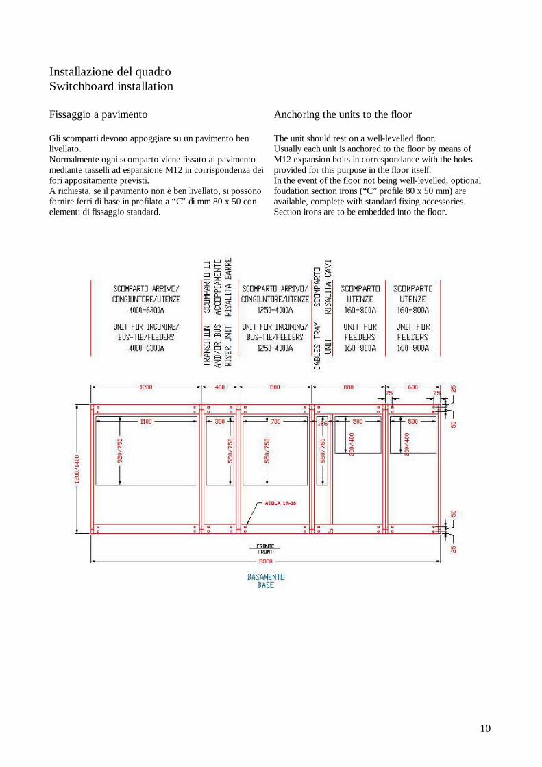
Installazione del quadro Switchboard installation Fissaggio a pavimento Gli scomparti devono appoggiare su un pavimento ben livellato. Normalmente ogni scomparto viene fissato al pavimento mediante tasselli ad espansione M12 in corrispondenza dei fori appositamente previsti. A richiesta, se il pavimento non è ben livellato, si possono fornire ferri di base in profilato a “C” di mm 80 x 50 con elementi di fissaggio standard.
Anchoring the units to the floor The unit should rest on a well-levelled floor. Usually each unit is anchored to the floor by means of M12 expansion bolts in correspondance with the holes provided for this purpose in the floor itself. In the event of the floor not being well-levelled, optional foudation section irons (“C” profile 80 x 50 mm) are available, complete with standard fixing accessories. Section irons are to be embedded into the floor.
11
Installazione del quadro Switchboard installation
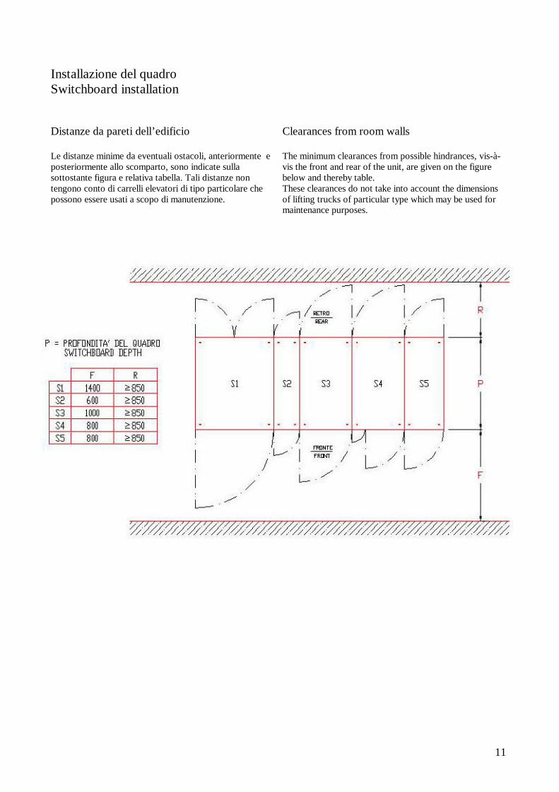
Distanze da pareti dell’edificio Le distanze minime da eventuali ostacoli, anteriormente e posteriormente allo scomparto, sono indicate sulla sottostante figura e relativa tabella. Tali distanze non tengono conto di carrelli elevatori di tipo particolare che possono essere usati a scopo di manutenzione.
Clearances from room walls The minimum clearances from possible hindrances, vis-à-vis the front and rear of the unit, are given on the figure below and thereby table. These clearances do not take into account the dimensions of lifting trucks of particular type which may be used for maintenance purposes.

12
Installazione del quadro Switchboard installation Movimentazione Per la movimentazione tramite gru o carroponte, prima di sollevare il quadro verificare le seguenti condizioni: - Ottimo stato delle funi o catene. - L’angolo tra le funi di sollevamento e il tetto del quadro
non deve essere>45°. - Peso massimo sollevabile.
Handling Before lifting the switchboard either with a crane or with bridge crane, following conditions must be verified:
- ropes and chains status - The angle between lifting ropes and switchboard
top must not be >45° - Max lifting weight.

13
Messa in servizio e manutenzione Start-up and maintenance instructions Messa in servizio - Effettuare un controllo a vista e controllare che
all’interno del quadro non permangano attrezzi o comunque corpi estranei.
- Verificare che tutti gli allacciamenti siano stati fatti con le dovute modalità.
- Verificare che le vibrazioni dovute al trasporto non abbiano provocato l’allentamento di qualche fusibile.
- Verificare che tutti i relè termici abbiano la taratura corrispondente allo schema funzionale.
- Effettuare una prova di isolamento del quadro e dell’impianto collegato utilizzando un misuratore di isolamento a 500Vcc. Le indicazioni non devono essere inferiori a 50Mohm.
Starting
- Carry out sight control and be sure that inside the board no tools or body sizes have been left.
- Verify that all connections are made in the best way. - Verify that all fuses are screwed on fuseholders.
Verify that all thermal relays are calibrated for schematic diagram.
- Using 500Vdc. Megger carry out insulating test . 50Mohm insulating value is minimum requested.
Manutenzione Almeno una volta all’anno, in occasione della messa fuori servizio del quadro:
- Togliere l’eventuale deposito di polvere sui supporti delle sbarre
- Ripassare i vari bulloni assicurandosi che siano ben avvitati.
- Per tutti i lavori da eseguire sul quadro in tensione attenersi al D.P.R N.547 ed in particolare all’Art.344
Maintenance Every year, when board is out of work:
- Remove possible dust from bars holders. - Control bolts and be sure that they are tightened - For all works to be carried out on energized
board comply with D.P.R.N.547 , in particular to clause 344
Sicurezza Sicurezza del personale - messa a terra di tutta la struttura del quadro - accessibilità agli apparecchi senza pericolo di contatto
con parti in tensione del circuito di potenza. Sicurezza contro l’incendio - materiali isolanti autoestinguenti - divisori interni e segregazioni metalliche
Safety Personnel safety - the entire metal structure is earthed - access to equipment without risk of contact with live
parts of the power circuits Fire hazard safety
- self-extinguishing insulating materials - internal metal partitions and segregations

14

15
www.ortecspa.it [email protected]
[email protected] [email protected]
[email protected] [email protected]
C.C.I.A.A. 00269010104 Meccanografico GE 026029 Capitale Sociale € 208.000,00 Int. versato Codice Fiscale / Partita IVA 00269010104 TRIBUNALE DI GENOVA 26662
16129 GENOVA - Via dei Pescatori - Tel. +39 010 25333.1 - Fax. +39 010 2530253
rtecINDUSTRIALE S.p.A