
Misure di proprietà meccaniche di superficie - PTG · che ogni minerale è in grado di graffiare...
28
Misure di proprietà meccaniche di superficie modulo: Proprietà viscoelastiche e proprietà meccaniche dei polimeri R. Pantani
-
Upload
vuongquynh -
Category
Documents
-
view
214 -
download
0
Transcript of Misure di proprietà meccaniche di superficie - PTG · che ogni minerale è in grado di graffiare...
Misure di proprietà meccaniche di superficie
modulo: Proprietà viscoelastiche e proprietà meccaniche dei polimeri
R. Pantani
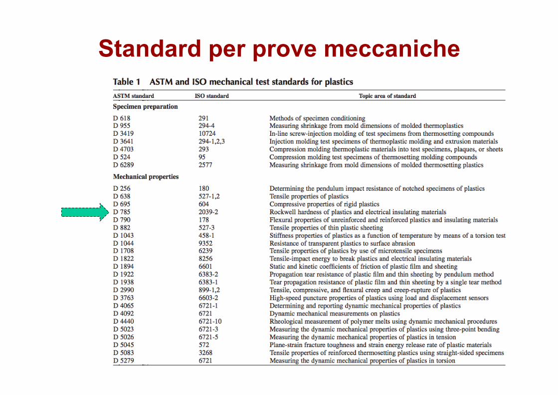
Standard per prove meccaniche
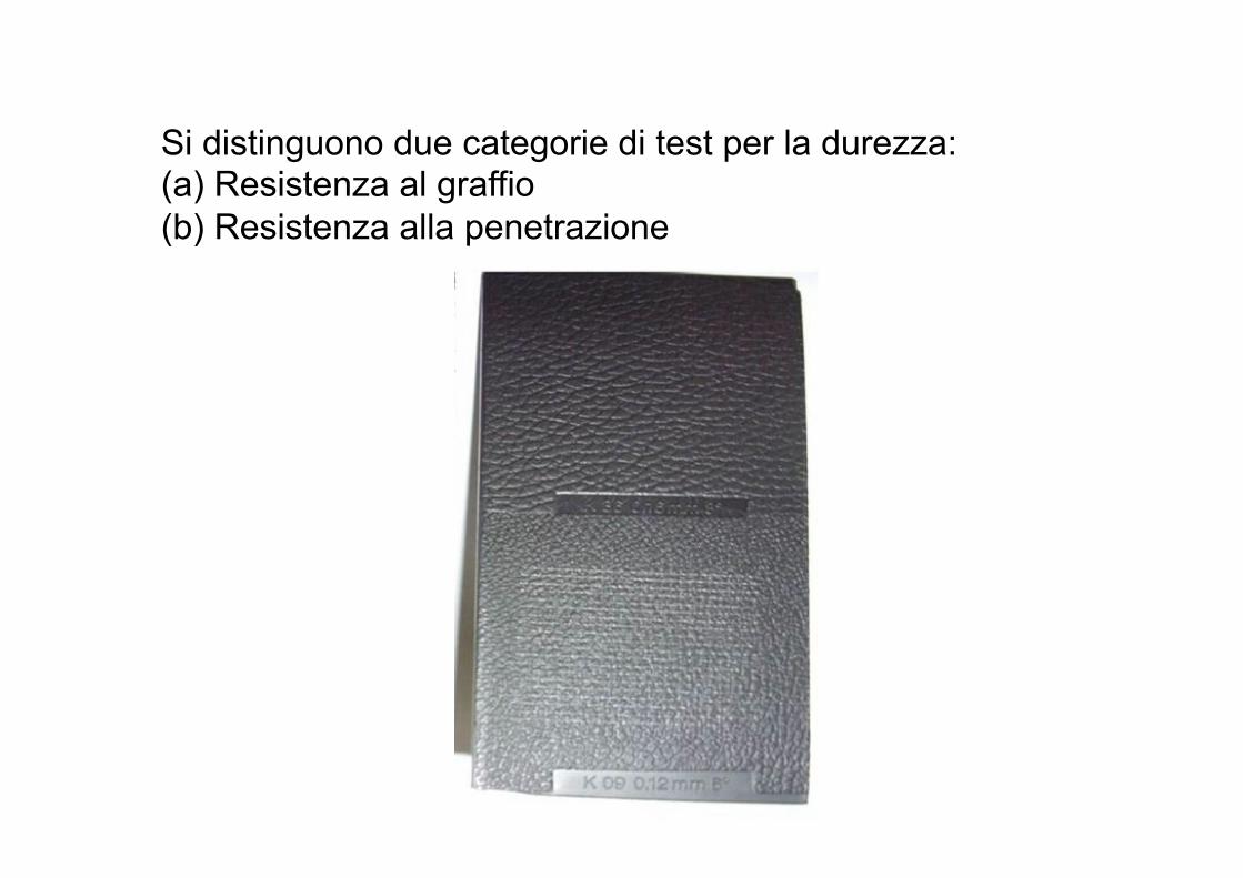
Si distinguono due categorie di test per la durezza: (a) Resistenza al graffio (b) Resistenza alla penetrazione
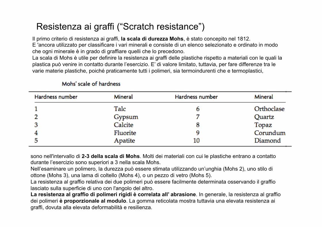
Resistenza ai graffi (“Scratch resistance”) Il primo criterio di resistenza ai graffi, la scala di durezza Mohs, è stato concepito nel 1812. E 'ancora utilizzato per classificare i vari minerali e consiste di un elenco selezionato e ordinato in modo che ogni minerale è in grado di graffiare quelli che lo precedono. La scala di Mohs è utile per definire la resistenza ai graffi delle plastiche rispetto a materiali con le quali la plastica può venire in contatto durante l’esercizio. E’ di valore limitato, tuttavia, per fare differenze tra le varie materie plastiche, poiché praticamente tutti i polimeri, sia termoindurenti che e termoplastici,
sono nell'intervallo di 2-3 della scala di Mohs. Molti dei materiali con cui le plastiche entrano a contatto durante l’esercizio sono superiori a 3 nella scala Mohs. Nell’esaminare un polimero, la durezza può essere stimata utilizzando un’unghia (Mohs 2), uno stilo di ottone (Mohs 3), una lama di coltello (Mohs 4), o un pezzo di vetro (Mohs 5). La resistenza al graffio relativa dei due polimeri può essere facilmente determinata osservando il graffio lasciato sulla superficie di uno con l'angolo del altro. La resistenza al graffio di polimeri rigidi è correlata all’ abrasione. In generale, la resistenza al graffio dei polimeri è proporzionale al modulo. La gomma reticolata mostra tuttavia una elevata resistenza ai graffi, dovuta alla elevata deformabilità e resilienza.
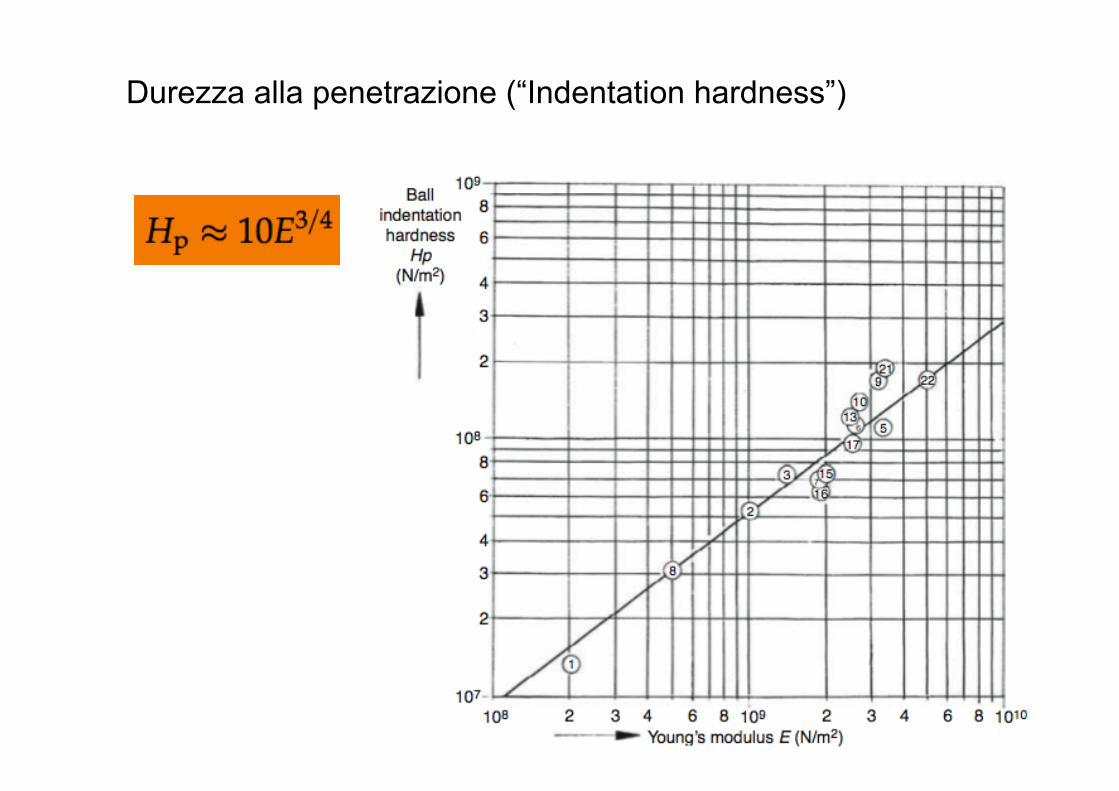
Durezza alla penetrazione (“Indentation hardness”)
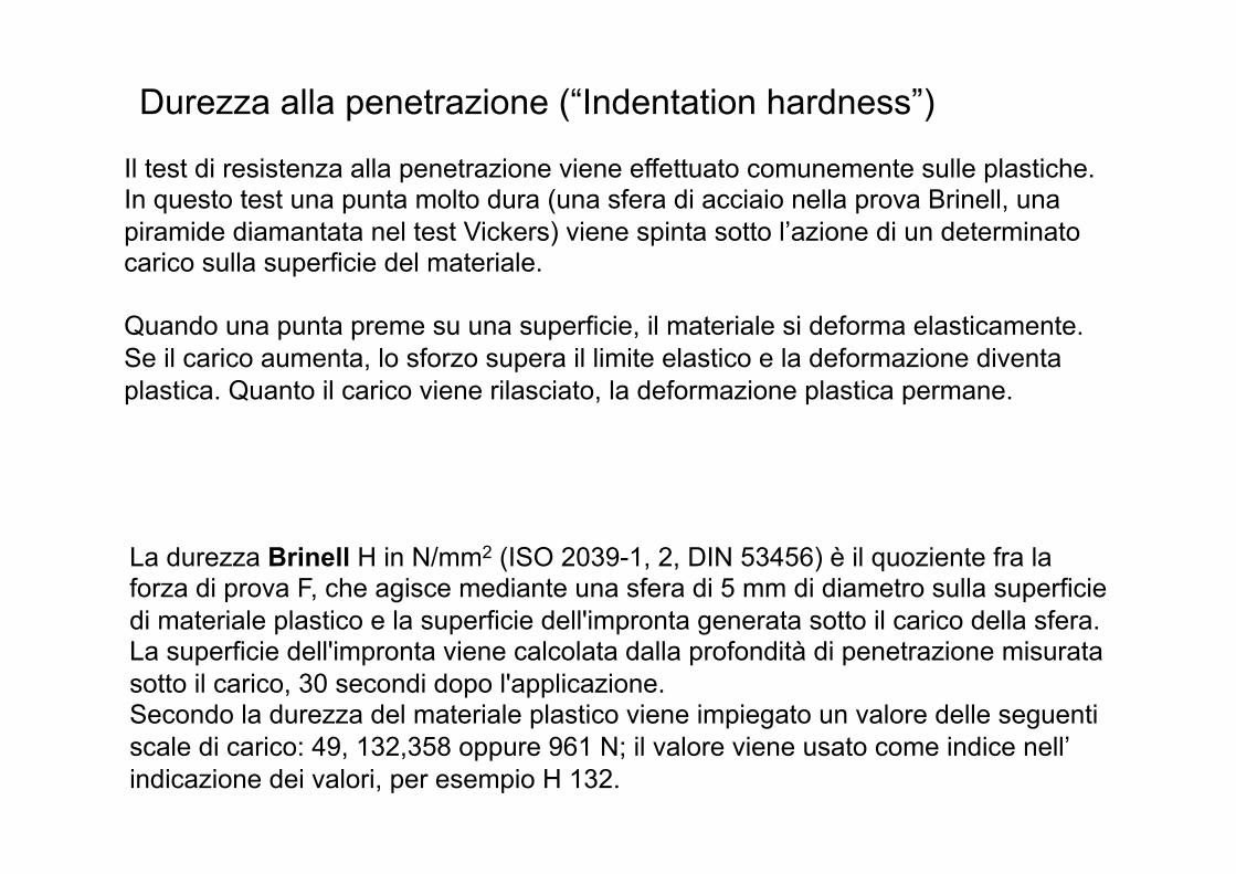
Il test di resistenza alla penetrazione viene effettuato comunemente sulle plastiche. In questo test una punta molto dura (una sfera di acciaio nella prova Brinell, una piramide diamantata nel test Vickers) viene spinta sotto l’azione di un determinato carico sulla superficie del materiale. Quando una punta preme su una superficie, il materiale si deforma elasticamente. Se il carico aumenta, lo sforzo supera il limite elastico e la deformazione diventa plastica. Quanto il carico viene rilasciato, la deformazione plastica permane.
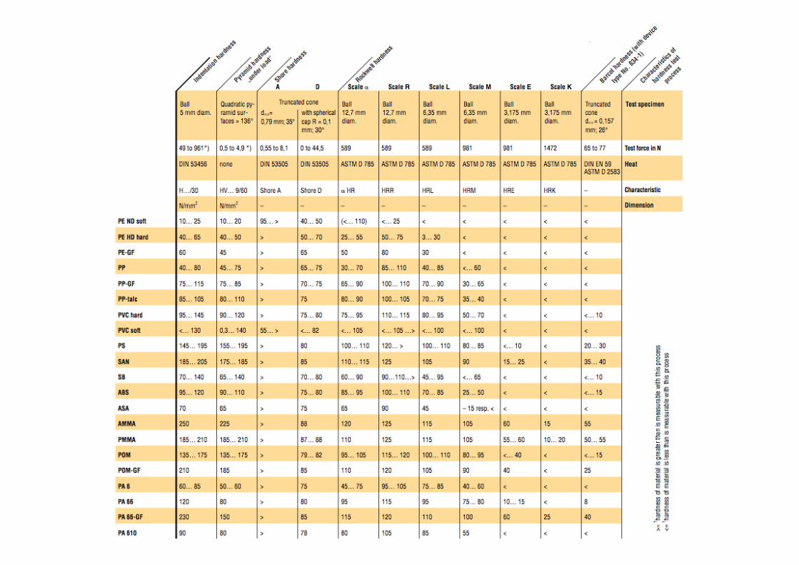
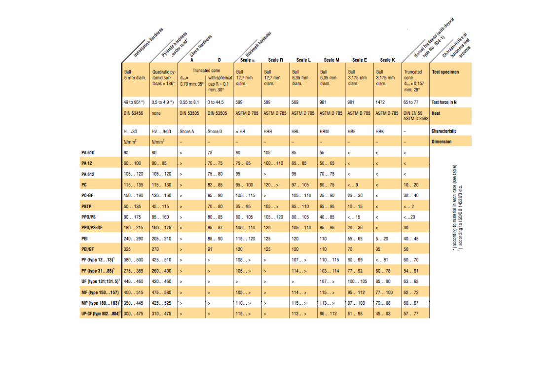
La durezza Brinell H in N/mm2 (ISO 2039-1, 2, DIN 53456) è il quoziente fra la forza di prova F, che agisce mediante una sfera di 5 mm di diametro sulla superficie di materiale plastico e la superficie dell'impronta generata sotto il carico della sfera. La superficie dell'impronta viene calcolata dalla profondità di penetrazione misurata sotto il carico, 30 secondi dopo l'applicazione. Secondo la durezza del materiale plastico viene impiegato un valore delle seguenti scale di carico: 49, 132,358 oppure 961 N; il valore viene usato come indice nell’ indicazione dei valori, per esempio H 132.
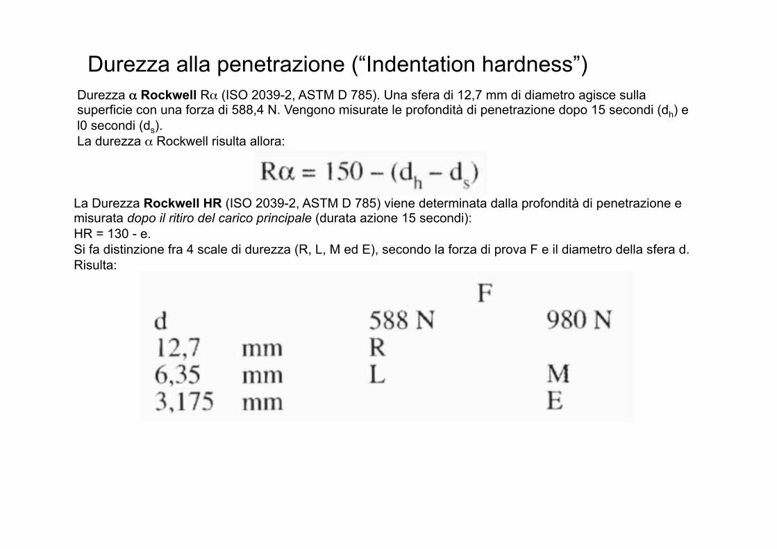
Durezza α Rockwell Rα (ISO 2039-2, ASTM D 785). Una sfera di 12,7 mm di diametro agisce sulla superficie con una forza di 588,4 N. Vengono misurate le profondità di penetrazione dopo 15 secondi (dh) e l0 secondi (ds). La durezza α Rockwell risulta allora:
La Durezza Rockwell HR (ISO 2039-2, ASTM D 785) viene determinata dalla profondità di penetrazione e misurata dopo il ritiro del carico principale (durata azione 15 secondi): HR = 130 - e. Si fa distinzione fra 4 scale di durezza (R, L, M ed E), secondo la forza di prova F e il diametro della sfera d. Risulta:
Durezza alla penetrazione (“Indentation hardness”)
Durezza alla penetrazione (“Indentation hardness”)
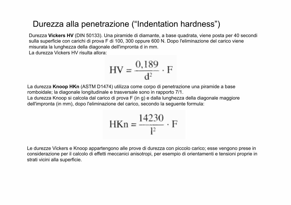
Durezza Vickers HV (DIN 50133). Una piramide di diamante, a base quadrata, viene posta per 40 secondi sulla superficie con carichi di prova F di 100, 300 oppure 600 N. Dopo l'eliminazione del carico viene misurata la lunghezza della diagonale dell'impronta d in mm. La durezza Vickers HV risulta allora:
La durezza Knoop HKn (ASTM D1474) utilizza come corpo di penetrazione una piramide a base romboidale; la diagonale longitudinale e trasversale sono in rapporto 7/1. La durezza Knoop si calcola dal carico di prova F (in g) e dalla lunghezza della diagonale maggiore dell'impronta (in mm), dopo l'eliminazione del carico, secondo la seguente formula:
Le durezze Vickers e Knoop appartengono alle prove di durezza con piccolo carico; esse vengono prese in considerazione per il calcolo di effetti meccanici anisotropi, per esempio di orientamenti e tensioni proprie in strati vicini alla superficie.
Durezza alla penetrazione (“Indentation hardness”)
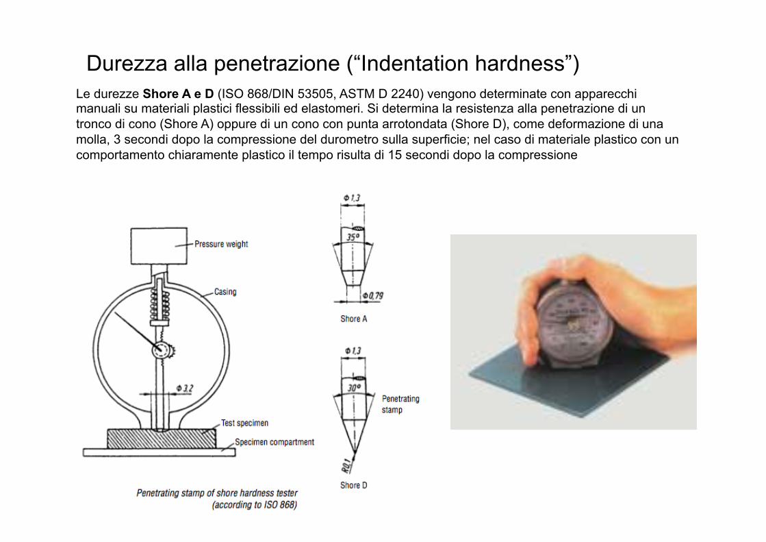
Le durezze Shore A e D (ISO 868/DIN 53505, ASTM D 2240) vengono determinate con apparecchi manuali su materiali plastici flessibili ed elastomeri. Si determina la resistenza alla penetrazione di un tronco di cono (Shore A) oppure di un cono con punta arrotondata (Shore D), come deformazione di una molla, 3 secondi dopo la compressione del durometro sulla superficie; nel caso di materiale plastico con un comportamento chiaramente plastico il tempo risulta di 15 secondi dopo la compressione
Durezza alla penetrazione (“Indentation hardness”)

La durezza Barcol (DIN EN 59, ASTM D2583) viene determinata come la durezza Shore con un apparecchio manuale e un tronco di cono con una punta piatta di 0,157 mm il test viene principalmente usato per misurare la durezza di plastiche rigide (rinforzate e non rinforzate). Il valore di durezza è ottenuto misurando la resistenza alla penetrazione di un punto d'acciaio tagliente sotto un carico della molla. Lo strumento, chiamato Barcol Impressor , consente una lettura diretta su una scala da 0 a 100. Il valore di durezza viene spesso utilizzato come misura del grado di polimerizzazione di una plastica o per il controllo del processo di indurimento (ad es. in resine di poliestere insature).
Durezza alla penetrazione (“Indentation hardness”)
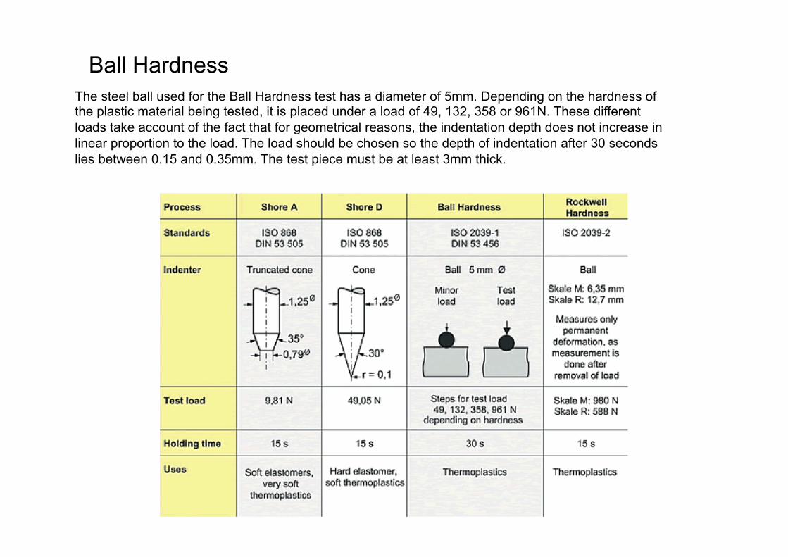
Ball Hardness The steel ball used for the Ball Hardness test has a diameter of 5mm. Depending on the hardness of the plastic material being tested, it is placed under a load of 49, 132, 358 or 961N. These different loads take account of the fact that for geometrical reasons, the indentation depth does not increase in linear proportion to the load. The load should be chosen so the depth of indentation after 30 seconds lies between 0.15 and 0.35mm. The test piece must be at least 3mm thick.
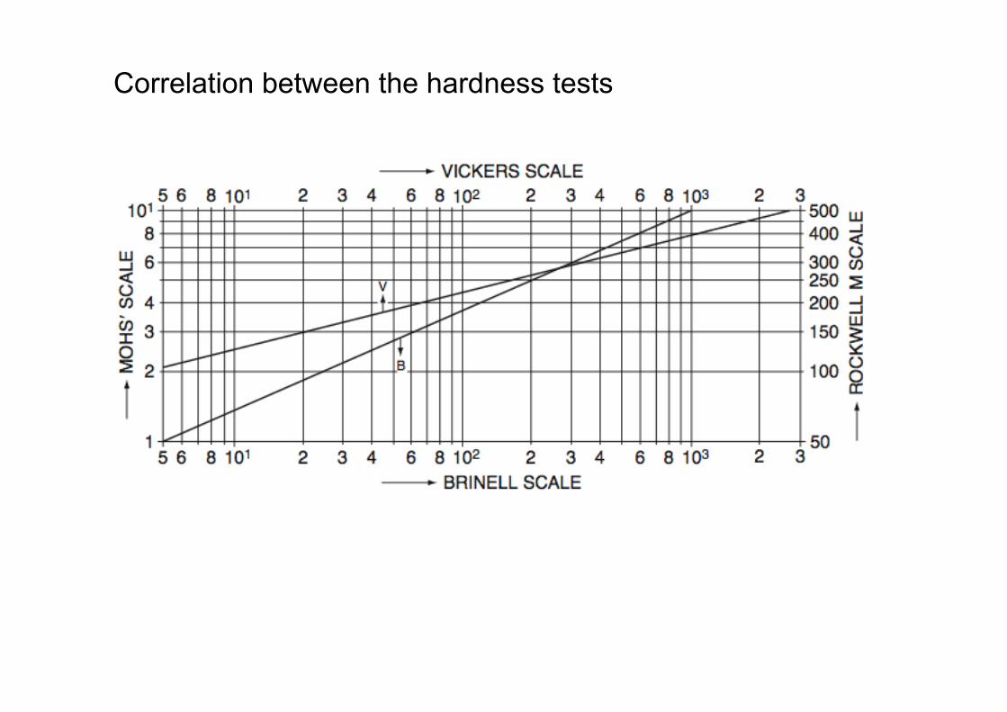
Correlation between the hardness tests
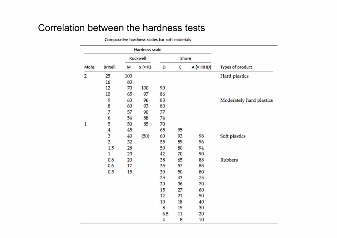
Correlation between the hardness tests
Durezza alla penetrazione (“Indentation hardness”)
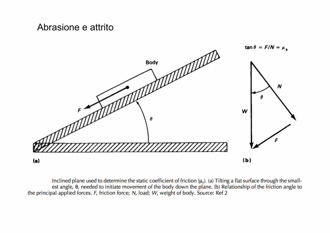
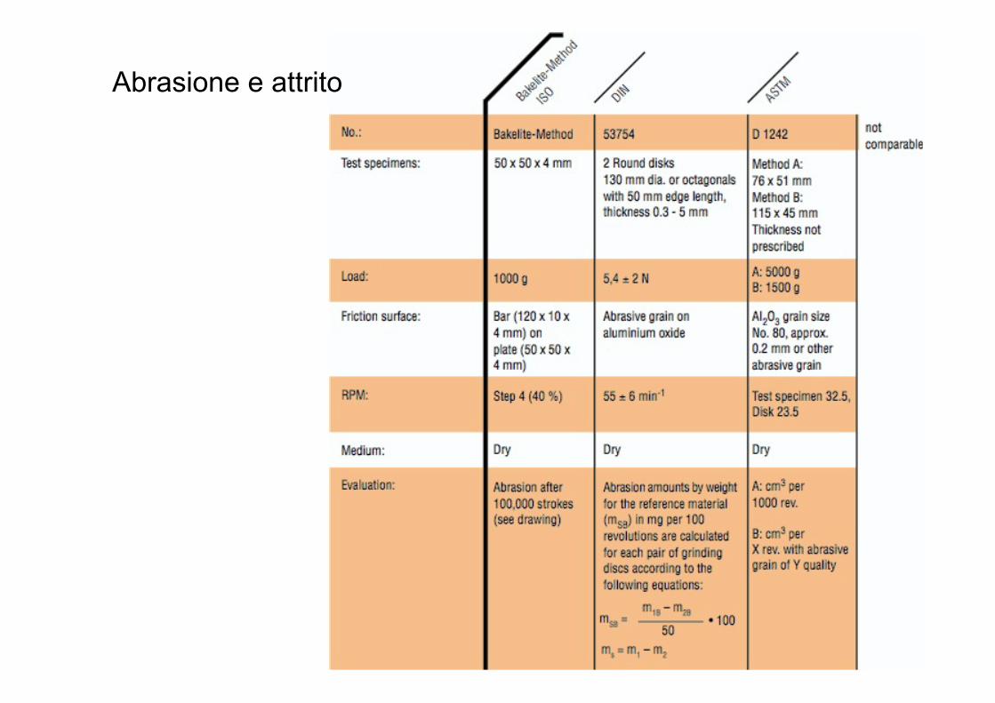
Abrasione e attrito
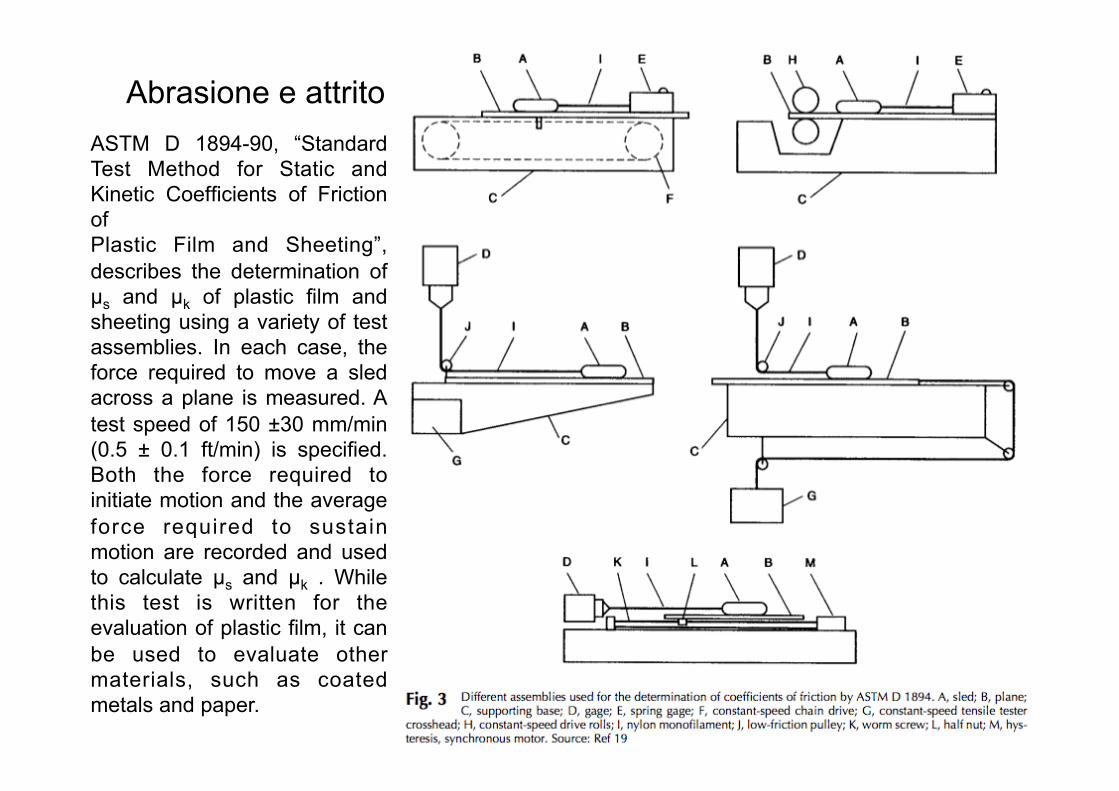
Abrasione e attrito ASTM D 1894-90, “Standard Test Method for Static and Kinetic Coefficients of Friction of Plastic Film and Sheeting”, describes the determination of µs and µk of plastic film and sheeting using a variety of test assemblies. In each case, the force required to move a sled across a plane is measured. A test speed of 150 ±30 mm/min (0.5 ± 0.1 ft/min) is specified. Both the force required to initiate motion and the average force required to sustain motion are recorded and used to calculate µs and µk . While this test is written for the evaluation of plastic film, it can be used to evaluate other materials, such as coated metals and paper.
Abrasione e attrito ASTM D 3028-90, “Standard Test Method for Kinetic Coefficient of Friction of Plastic Solids”, uses a variable-speed frictionometer to measure kinetic coefficients of friction. Three types of test specimens can be used: 20.0 ±0.1 mm diameter rigid fixed specimens that weigh 5.0 ±0.1 g, 100.0 ±0.1 mm diameter rigid moving specimens, or film or sheeting mounted on a 100 mm diameter mounting wheel. Two procedures are described. In procedure A, coefficients of friction are measured at velocities of 0.25, 0.50, 1.0, 2.0, and 3.0 m/s. The test is performed as rapidly as possible to minimize wear effects. Testing performed by procedure B is intended to show the effects of time, velocity, and wear on coefficient of friction. A velocity is selected (1.0 m/s is suggested as a default), and readings are taken every 30 s until they reach a constant value. The relationship between wear and friction is an important consideration when selecting a friction test. Several ways in which wear may affect friction are illustrated in Fig. 4. Figure 4(a) shows how friction force varies with time when a system experiences no wear. The friction is essentially constant. Figure 4(b) shows a system where the friction force increases with time and finally reaches a steady state. This type of behav- ior may be seen in a system where both surfaces experience heavy wear: The coefficient of fric- tion is low for the original surfaces, but it rises and stabilizes as new surfaces are exposed. Fig- ure 4(c) shows a system that experiences a vari- ety of wear events. Friction changes as the wear processes change. This type of behavior may be observed in a system where retained wear debris can either increase or decrease friction. If a system will wear, and the friction of worn surfaces is of interest, friction should be mea- sured in a test that produces wear. ASTM D 3028-90, described previously, has that capa- bility, as do several of the wear tests described subsequently.

Abrasione e attrito
Abrasione e attrito
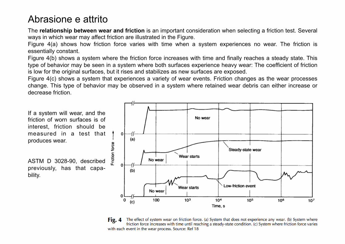
Abrasione e attrito The relationship between wear and friction is an important consideration when selecting a friction test. Several ways in which wear may affect friction are illustrated in the Figure. Figure 4(a) shows how friction force varies with time when a system experiences no wear. The friction is essentially constant. Figure 4(b) shows a system where the friction force increases with time and finally reaches a steady state. This type of behavior may be seen in a system where both surfaces experience heavy wear: The coefficient of friction is low for the original surfaces, but it rises and stabilizes as new surfaces are exposed. Figure 4(c) shows a system that experiences a variety of wear events. Friction changes as the wear processes change. This type of behavior may be observed in a system where retained wear debris can either increase or decrease friction.
If a system will wear, and the friction of worn surfaces is of interest, friction should be measured in a test that produces wear. ASTM D 3028-90, described previously, has that capa- bility.
Abrasione e attrito
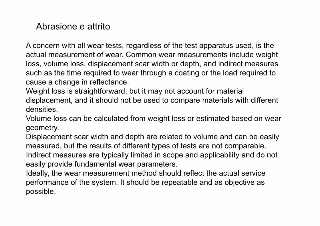
A concern with all wear tests, regardless of the test apparatus used, is the actual measurement of wear. Common wear measurements include weight loss, volume loss, displacement scar width or depth, and indirect measures such as the time required to wear through a coating or the load required to cause a change in reflectance. Weight loss is straightforward, but it may not account for material displacement, and it should not be used to compare materials with different densities. Volume loss can be calculated from weight loss or estimated based on wear geometry. Displacement scar width and depth are related to volume and can be easily measured, but the results of different types of tests are not comparable. Indirect measures are typically limited in scope and applicability and do not easily provide fundamental wear parameters. Ideally, the wear measurement method should reflect the actual service performance of the system. It should be repeatable and as objective as possible.
Abrasione e attrito
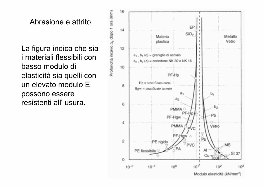
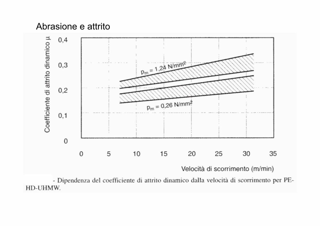
La figura indica che sia i materiali flessibili con basso modulo di elasticità sia quelli con un elevato modulo E possono essere resistenti all' usura.
Abrasione e attrito
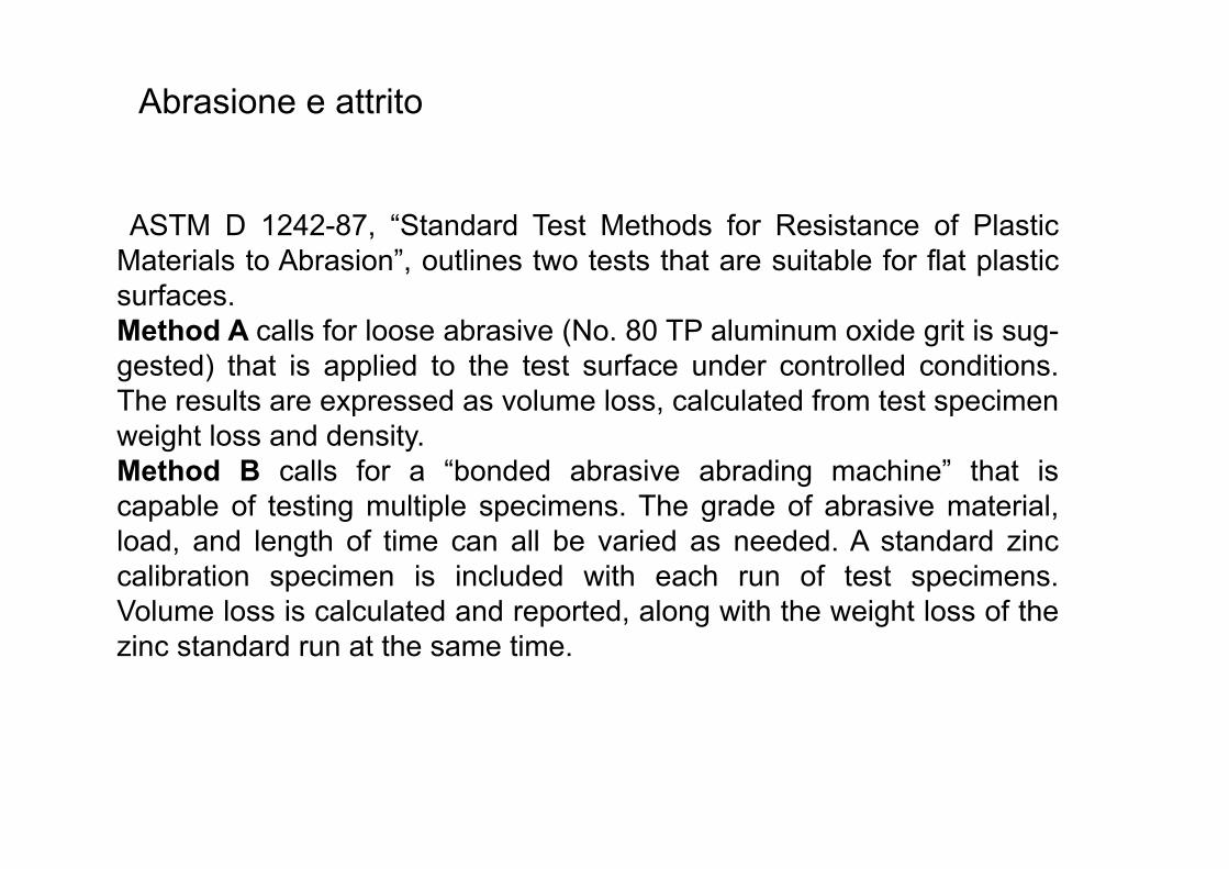
ASTM D 1242-87, “Standard Test Methods for Resistance of Plastic Materials to Abrasion”, outlines two tests that are suitable for flat plastic surfaces. Method A calls for loose abrasive (No. 80 TP aluminum oxide grit is sug- gested) that is applied to the test surface under controlled conditions. The results are expressed as volume loss, calculated from test specimen weight loss and density. Method B calls for a “bonded abrasive abrading machine” that is capable of testing multiple specimens. The grade of abrasive material, load, and length of time can all be varied as needed. A standard zinc calibration specimen is included with each run of test specimens. Volume loss is calculated and reported, along with the weight loss of the zinc standard run at the same time.
Abrasione e attrito
Abrasione e attrito
PV Limit
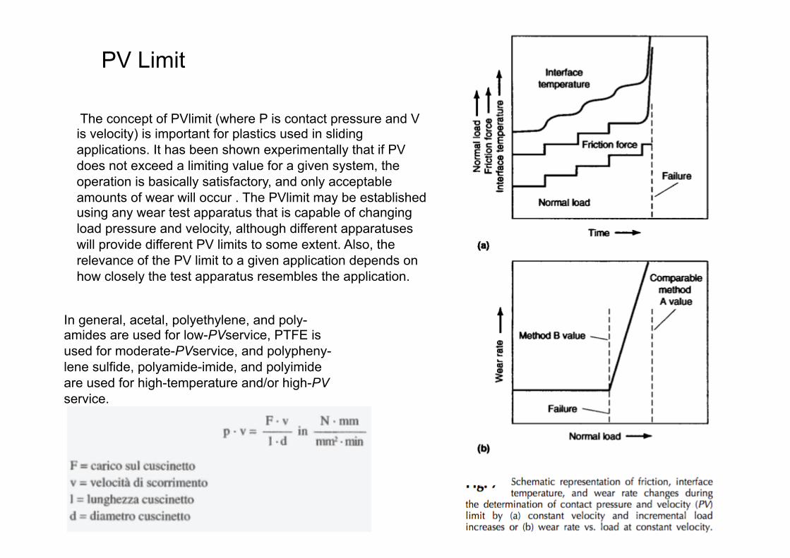
The concept of PVlimit (where P is contact pressure and V is velocity) is important for plastics used in sliding applications. It has been shown experimentally that if PV does not exceed a limiting value for a given system, the operation is basically satisfactory, and only acceptable amounts of wear will occur . The PVlimit may be established using any wear test apparatus that is capable of changing load pressure and velocity, although different apparatuses will provide different PV limits to some extent. Also, the relevance of the PV limit to a given application depends on how closely the test apparatus resembles the application.
In general, acetal, polyethylene, and poly- amides are used for low-PVservice, PTFE is used for moderate-PVservice, and polypheny- lene sulfide, polyamide-imide, and polyimide are used for high-temperature and/or high-PV service.


![IRONWOOD - PAVE PAVIMENTAZIONI · durezza scala mohs 5-8 ≥ 5 [en 101] surface hardness duretÉ de surface escala de dureza mohs ritzhÄrte der oberflÄche gres porcellanato estruso](https://static.fdocumenti.com/doc/165x107/5f70ba4980eaf430ea1c2fc4/ironwood-pave-durezza-scala-mohs-5-8-a-5-en-101-surface-hardness-duret-de.jpg)