Media tensione primaria - Primary medium voltage QUaDRO ...
10
Media tensione primaria - Primary medium voltage QUADRO BIPIANO DOUBLE TIER SWITCHBOARD Per cabine primarie fino a 24 kV For primary sub-stations up to 24 kV
Transcript of Media tensione primaria - Primary medium voltage QUaDRO ...

Media tensione primaria - Primary medium voltage
QUaDRO BIPIaNODOUBLe tIeR SWItCHBOaRD
Per cabine primarie fino a 24 kVfor primary sub-stations up to 24 kV
Per cabine primarie fino a 24 kV
Con quadro bipiano si intende un quadro di tipo blindato per interno (cfr. Norme CEI 17-6), isolato in aria, in cui gli interruttori sono disposti in cel-le sovrapposte all’interno dello stesso scomparto. Il quadro è dotato di un semplice sistema di sbarre da 1250 A o 2500 A e impiega interruttori MT di tipo estraibile in esafluoruro di zolfo (SF6) o in vuoto. Il quadro può essere installato con disposizione su un’unica fila o su due file affacciate tra di loro. La disposizione scelta è funzione delle dimensioni della sala quadri. Il quadro Bipiano protetto in aria ha la caratteristica di essere strutturato in scompar-ti su cui sono sovrapposte le seguenti coppie di celle: Congiuntore-Linea, Linea-Rifasamento, Linea-Linea, TV-Trasformatore, TFN-Linea. Ogni scomparto è comprensivo di vano protezioni.
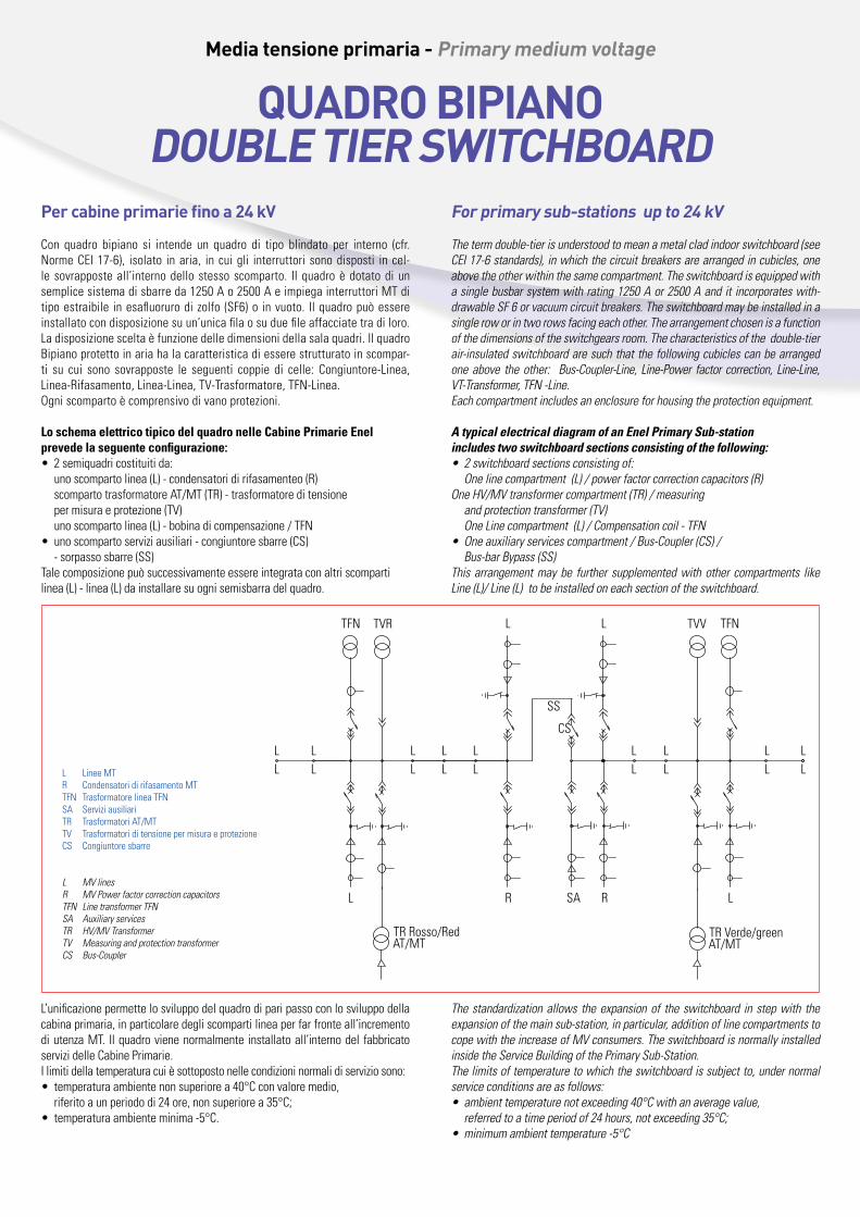
lo schema elettrico tipico del quadro nelle Cabine primarie Enel prevede la seguente configurazione:• 2 semiquadri costituiti da:
uno scomparto linea (L) - condensatori di rifasamenteo (R)scomparto trasformatore AT/MT (TR) - trasformatore di tensione per misura e protezione (TV) uno scomparto linea (L) - bobina di compensazione / TFN
• uno scomparto servizi ausiliari - congiuntore sbarre (CS) - sorpasso sbarre (SS)Tale composizione può successivamente essere integrata con altri scomparti linea (L) - linea (L) da installare su ogni semisbarra del quadro.
for primary sub-stations up to 24 kV
Thetermdouble-tierisunderstoodtomeanametalcladindoorswitchboard(seeCEI17-6standards),inwhichthecircuitbreakersarearrangedincubicles,oneabovetheotherwithinthesamecompartment.Theswitchboardisequippedwithasinglebusbarsystemwithrating1250Aor2500Aanditincorporateswith-drawableSF6orvacuumcircuitbreakers.Theswitchboardmaybeinstalledinasingleroworintworowsfacingeachother.Thearrangementchosenisafunctionofthedimensionsoftheswitchgearsroom.Thecharacteristicsofthedouble-tierair-insulatedswitchboardaresuchthatthefollowingcubiclescanbearrangedoneabove theother: Bus-Coupler-Line, Line-Power factor correction, Line-Line,VT-Transformer,TFN-Line.Eachcompartmentincludesanenclosureforhousingtheprotectionequipment.
a typical electrical diagram of an Enel Primary Sub-station includes two switchboard sections consisting of the following: • 2switchboardsectionsconsistingof: Onelinecompartment(L)/powerfactorcorrectioncapacitors(R)OneHV/MVtransformercompartment(TR)/measuringandprotectiontransformer(TV)OneLinecompartment(L)/Compensationcoil-TFN
• Oneauxiliaryservicescompartment/Bus-Coupler(CS)/ Bus-barBypass(SS)This arrangementmaybe further supplementedwithother compartments likeLine(L)/Line(L)tobeinstalledoneachsectionoftheswitchboard.
Media tensione primaria - Primary medium voltage
QUaDRO BIPIaNODOUBLe tIeR SWItCHBOaRD
L’unificazione permette lo sviluppo del quadro di pari passo con lo sviluppo della cabina primaria, in particolare degli scomparti linea per far fronte all’incremento di utenza MT. Il quadro viene normalmente installato all’interno del fabbricato servizi delle Cabine Primarie.I limiti della temperatura cui è sottoposto nelle condizioni normali di servizio sono:• temperatura ambiente non superiore a 40°C con valore medio,
riferito a un periodo di 24 ore, non superiore a 35°C;• temperatura ambiente minima -5°C.
Thestandardizationallows theexpansionof theswitchboard instepwith theexpansionofthemainsub-station,inparticular,additionoflinecompartmentstocopewiththeincreaseofMVconsumers.TheswitchboardisnormallyinstalledinsidetheServiceBuildingofthePrimarySub-Station.Thelimitsoftemperaturetowhichtheswitchboardissubjectto,undernormalserviceconditionsareasfollows:• ambienttemperaturenotexceeding40°Cwithanaveragevalue,referredtoatimeperiodof24hours,notexceeding35°C;
• minimumambienttemperature-5°C
L Linee MTR Condensatori di rifasamento MTTFN Trasformatore linea TFNSA Servizi ausiliariTR Trasformatori AT/MTTV Trasformatori di tensione per misura e protezioneCS Congiuntore sbarre
L MVlinesR MVPowerfactorcorrectioncapacitorsTFN LinetransformerTFNSA AuxiliaryservicesTR HV/MVTransformerTV MeasuringandprotectiontransformerCS Bus-Coupler
LL
LL
CS
TVR TVV
TR Verde/green
R
LL
TFN L L TFN
LL
LL R
LL
LL
SS
LL
LL
LL
SA
AT/MTAT/MTTR Rosso/Red
Media tensione primaria - Primary medium voltage
QUaDRO BIPIaNODOUBLe tIeR SWItCHBOaRD
ComponEnti dEl Quadro
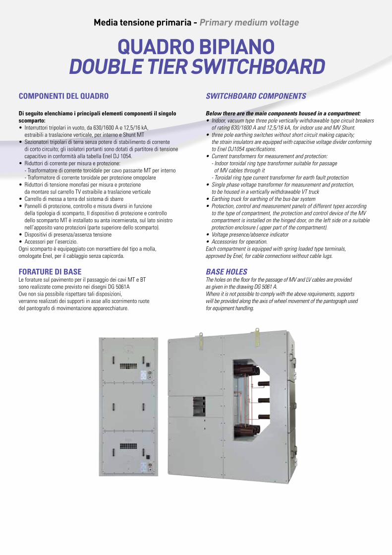
di seguito elenchiamo i principali elementi componenti il singolo scomparto:• Interruttori tripolari in vuoto, da 630/1600 A e 12,5/16 kA,
estraibili a traslazione verticale, per interno e Shunt MT• Sezionatori tripolari di terra senza potere di stabilimento di corrente
di corto circuito; gli isolatori portanti sono dotati di partitore di tensione capacitivo in conformità alla tabella Enel DJ 1054.
• Riduttori di corrente per misura e protezione:- Trasformatore di corrente toroidale per cavo passante MT per interno- Traformatore di corrente toroidale per protezione omopolare
• Riduttori di tensione monofasi per misura e protezione da montare sul carrello TV estraibile a traslazione verticale
• Carrello di messa a terra del sistema di sbarre• Pannelli di protezione, controllo e misura diversi in funzione
della tipologia di scomparto, Il dispositivo di protezione e controllo dello scomparto MT è installato su anta incernierata, sul lato sinistro nell’apposito vano protezioni (parte superiore dello scomparto).
• Dispositivi di presenza/assenza tensione• Accessori per l’esercizio.Ogni scomparto è equipaggiato con morsettiere del tipo a molla, omologate Enel, per il cablaggio senza capicorda.
foraturE di baSELe forature sul pavimento per il passaggio dei cavi MT e BT sono realizzate come previsto nei disegni DG 5061AOve non sia possibile rispettare tali disposizioni, verranno realizzati dei supporti in asse allo scorrimento ruotedel pantografo di movimentazione apparecchiature.
SWItCHBOard COMPOnEntS
Below there are the main components housed in a compartment:• Indoor,vacuumtypethreepoleverticallywithdrawabletypecircuitbreakersofrating630/1600Aand12,5/16kA,forindooruseandMVShunt.
• threepoleearthingswitcheswithoutshortcircuitmakingcapacity;thestraininsulatorsareequippedwithcapacitivevoltagedividerconformingtoEnelDJ1054specifications.
• Currenttransformersformeasurementandprotection:-IndoortoroidalringtypetransformersuitableforpassageofMVcablesthroughit-Toroidalringtypecurrenttransformerforearthfaultprotection
• Singlephasevoltagetransformerformeasurementandprotection,tobehousedinaverticallywithdrawableVTtruck
• Earthingtruckforearthingofthebus-barsystem• Protection,controlandmeasurementpanelsofdifferenttypesaccordingtothetypeofcompartment,theprotectionandcontroldeviceoftheMVcompartmentisinstalledonthehingeddoor,ontheleftsideonasuitableprotectionenclosure(upperpartofthecompartment).
• Voltagepresence/absenceindicator• Accessoriesforoperation.Eachcompartmentisequippedwithspringloadedtypeterminals,approvedbyEnel,forcableconnectionswithoutcablelugs.
BaSE HOLES TheholesonthefloorforthepassageofMVandLVcablesareprovidedasgiveninthedrawingDG5061A.Whereitisnotpossibletocomplywiththeaboverequirements,supportswillbeprovidedalongtheaxisofwheelmovementofthepantographusedforequipmenthandling.
CritEri prinCipali adottati pEr la rEaliZZaZionE dEl Quadro 24 kV:
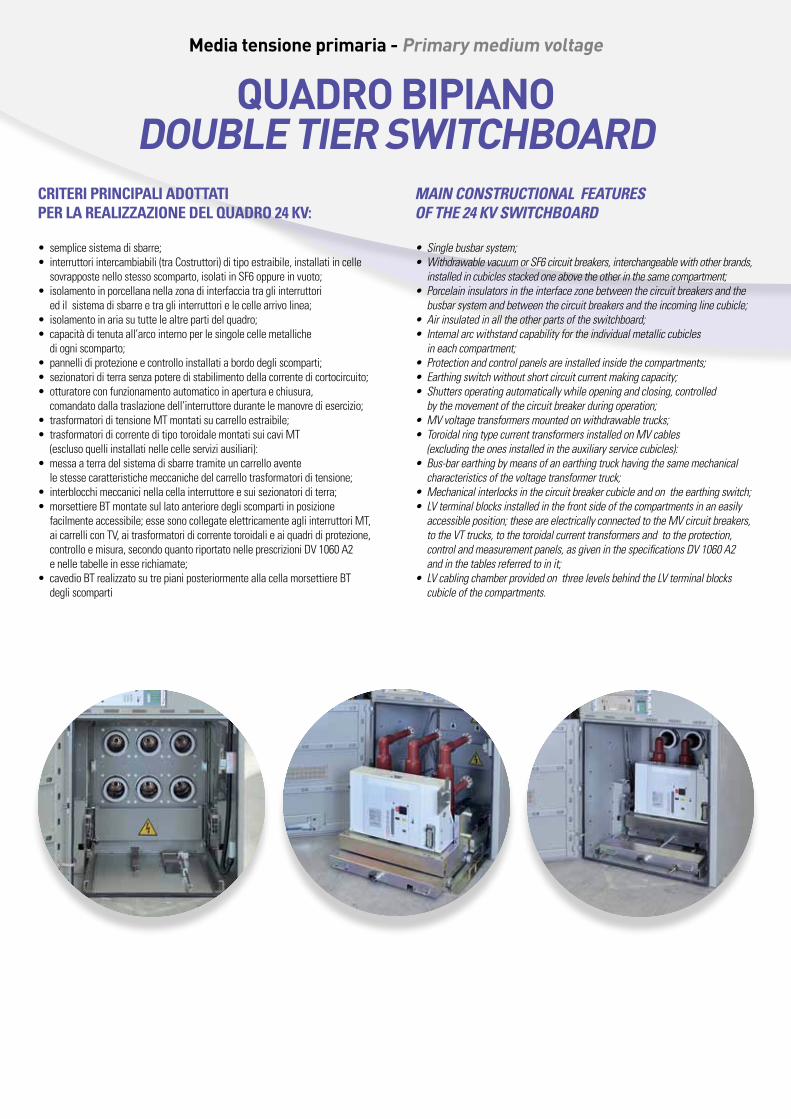
• semplice sistema di sbarre;• interruttori intercambiabili (tra Costruttori) di tipo estraibile, installati in celle
sovrapposte nello stesso scomparto, isolati in SF6 oppure in vuoto;• isolamento in porcellana nella zona di interfaccia tra gli interruttori
ed il sistema di sbarre e tra gli interruttori e le celle arrivo linea;• isolamento in aria su tutte le altre parti del quadro;• capacità di tenuta all’arco interno per le singole celle metalliche
di ogni scomparto;• pannelli di protezione e controllo installati a bordo degli scomparti;• sezionatori di terra senza potere di stabilimento della corrente di cortocircuito;• otturatore con funzionamento automatico in apertura e chiusura,
comandato dalla traslazione dell’interruttore durante le manovre di esercizio;• trasformatori di tensione MT montati su carrello estraibile;• trasformatori di corrente di tipo toroidale montati sui cavi MT
(escluso quelli installati nelle celle servizi ausiliari):• messa a terra del sistema di sbarre tramite un carrello avente
le stesse caratteristiche meccaniche del carrello trasformatori di tensione;• interblocchi meccanici nella cella interruttore e sui sezionatori di terra;• morsettiere BT montate sul lato anteriore degli scomparti in posizione
facilmente accessibile; esse sono collegate elettricamente agli interruttori MT, ai carrelli con TV, ai trasformatori di corrente toroidali e ai quadri di protezione, controllo e misura, secondo quanto riportato nelle prescrizioni DV 1060 A2 e nelle tabelle in esse richiamate;
• cavedio BT realizzato su tre piani posteriormente alla cella morsettiere BT degli scomparti
MaIn COnStrUCtIOnaL FEatUrES OF tHE 24 kV SWItCHBOard
• Singlebusbarsystem;• WithdrawablevacuumorSF6circuitbreakers,interchangeablewithotherbrands,installedincubiclesstackedoneabovetheotherinthesamecompartment;
• Porcelaininsulatorsintheinterfacezonebetweenthecircuitbreakersandthebusbarsystemandbetweenthecircuitbreakersandtheincominglinecubicle;
• Airinsulatedinalltheotherpartsoftheswitchboard;• Internalarcwithstandcapabilityfortheindividualmetalliccubiclesineachcompartment;
• Protectionandcontrolpanelsareinstalledinsidethecompartments;• Earthingswitchwithoutshortcircuitcurrentmakingcapacity;• Shuttersoperatingautomaticallywhileopeningandclosing,controlledbythemovementofthecircuitbreakerduringoperation;
• MVvoltagetransformersmountedonwithdrawabletrucks;• ToroidalringtypecurrenttransformersinstalledonMVcables(excludingtheonesinstalledintheauxiliaryservicecubicles):
• Bus-barearthingbymeansofanearthingtruckhavingthesamemechanicalcharacteristicsofthevoltagetransformertruck;
• Mechanicalinterlocksinthecircuitbreakercubicleandontheearthingswitch;• LVterminalblocksinstalledinthefrontsideofthecompartmentsinaneasilyaccessibleposition;theseareelectricallyconnectedtotheMVcircuitbreakers,totheVTtrucks,tothetoroidalcurrenttransformersandtotheprotection,controlandmeasurementpanels,asgiveninthespecificationsDV1060A2andinthetablesreferredtoinit;
• LVcablingchamberprovidedonthreelevelsbehindtheLVterminalblockscubicleofthecompartments.
Media tensione primaria - Primary medium voltage
QUaDRO BIPIaNODOUBLe tIeR SWItCHBOaRD
Media tensione primaria - Primary medium voltage
QUaDRO BIPIaNODOUBLe tIeR SWItCHBOaRD
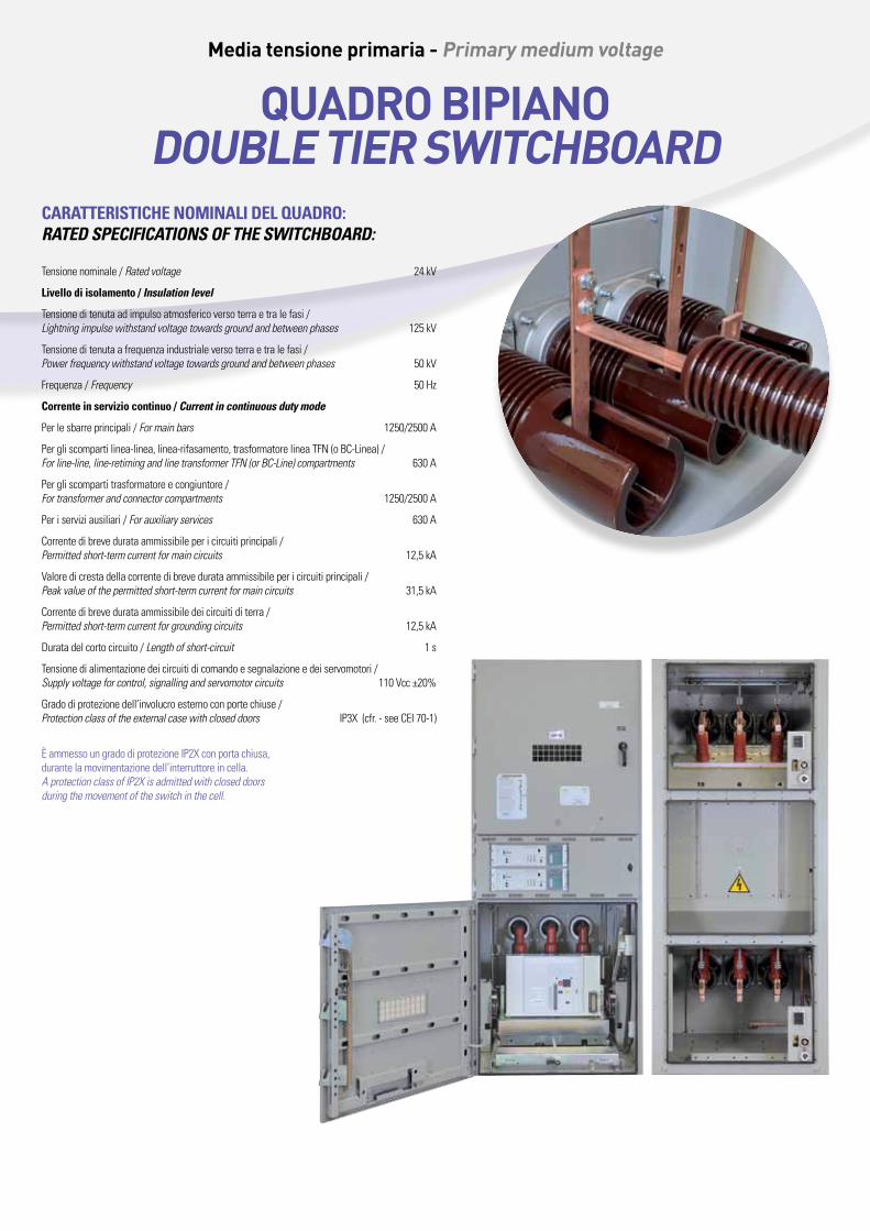
CarattEriStiCHE nominali dEl Quadro:ratEd SPECIFICatIOnS OF tHE SWItCHBOard:
Tensione nominale / Ratedvoltage 24 kV
livello di isolamento / Insulation level
Tensione di tenuta ad impulso atmosferico verso terra e tra le fasi /Lightningimpulsewithstandvoltagetowardsgroundandbetweenphases 125 kV
Tensione di tenuta a frequenza industriale verso terra e tra le fasi / Powerfrequencywithstandvoltagetowardsgroundandbetweenphases 50 kV
Frequenza / Frequency 50 Hz
Corrente in servizio continuo / Current in continuous duty mode
Per le sbarre principali / Formainbars 1250/2500 A
Per gli scomparti linea-linea, linea-rifasamento, trasformatore linea TFN (o BC-Linea) / Forline-line,line-retimingandlinetransformerTFN(orBC-Line)compartments 630 A
Per gli scomparti trasformatore e congiuntore / Fortransformerandconnectorcompartments 1250/2500 A
Per i servizi ausiliari / Forauxiliaryservices 630 A
Corrente di breve durata ammissibile per i circuiti principali / Permittedshort-termcurrentformaincircuits 12,5 kA
Valore di cresta della corrente di breve durata ammissibile per i circuiti principali / Peakvalueofthepermittedshort-termcurrentformaincircuits 31,5 kA
Corrente di breve durata ammissibile dei circuiti di terra / Permittedshort-termcurrentforgroundingcircuits 12,5 kA
Durata del corto circuito / Lengthofshort-circuit 1 s
Tensione di alimentazione dei circuiti di comando e segnalazione e dei servomotori / Supplyvoltageforcontrol,signallingandservomotorcircuits 110 Vcc ±20%
Grado di protezione dell’involucro esterno con porte chiuse / Protectionclassoftheexternalcasewithcloseddoors IP3X (cfr. - see CEI 70-1)
È ammesso un grado di protezione IP2X con porta chiusa, durante la movimentazione dell’interruttore in cella.AprotectionclassofIP2Xisadmittedwithcloseddoorsduringthemovementoftheswitchinthecell.
QUaDRO BIPIaNO - DOUBLe tIeR SWItCHBOaRDModelli e dimensioni - Types and dimensions
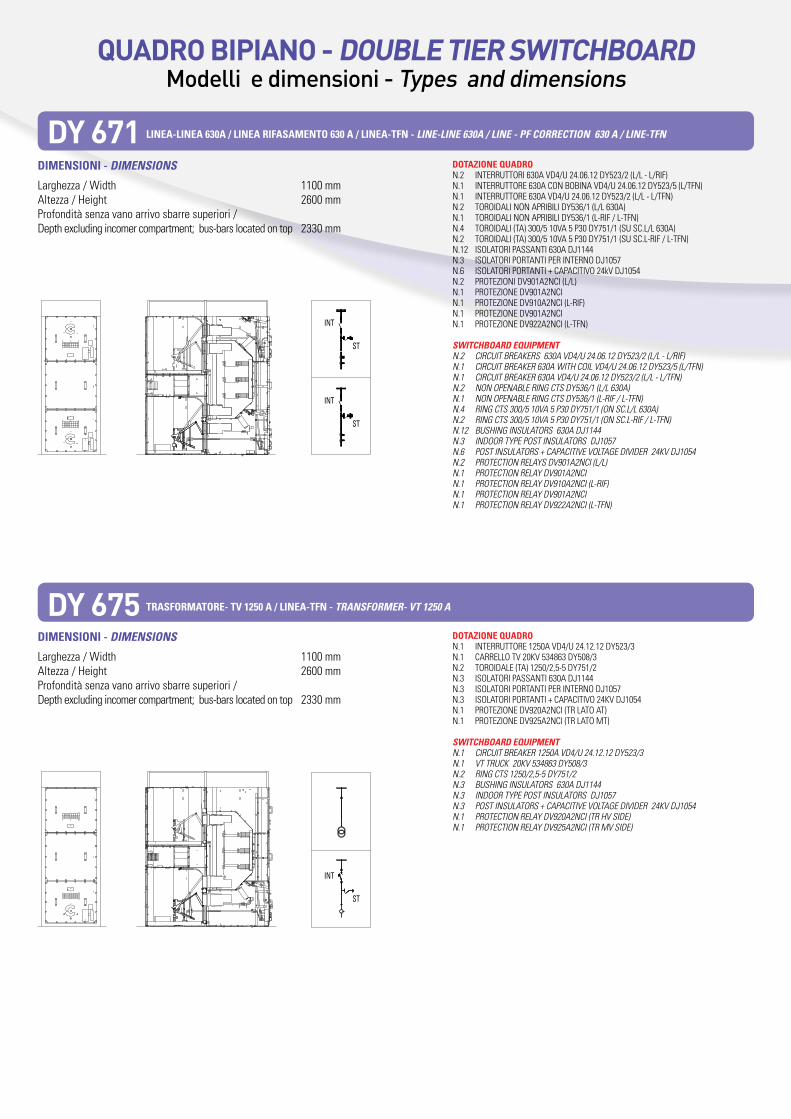
DY 671 linEa-linEa 630a / linEa rifaSamEnto 630 a / linEa-tfn - LInE-LInE 630a / LInE - PF COrrECtIOn 630 a / LInE-tFn
DY 675 traSformatorE- tV 1250 a / linEa-tfn - tranSFOrMEr- Vt 1250 a
dimEnSioni - dIMEnSIOnS
Larghezza / Width 1100 mmAltezza / Height 2600 mmProfondità senza vano arrivo sbarre superiori / Depth excluding incomer compartment; bus-bars located on top 2330 mm
dimEnSioni - dIMEnSIOnS
Larghezza / Width 1100 mmAltezza / Height 2600 mmProfondità senza vano arrivo sbarre superiori / Depth excluding incomer compartment; bus-bars located on top 2330 mm
dotaZionE QuadroN.2 INTERRUTTORI 630A VD4/U 24.06.12 DY523/2 (L/L - L/RIF) N.1 INTERRUTTORE 630A CON BOBINA VD4/U 24.06.12 DY523/5 (L/TFN) N.1 INTERRUTTORE 630A VD4/U 24.06.12 DY523/2 (L/L - L/TFN) N.2 TOROIDALI NON APRIBILI DY536/1 (L/L 630A) N.1 TOROIDALI NON APRIBILI DY536/1 (L-RIF / L-TFN) N.4 TOROIDALI (TA) 300/5 10VA 5 P30 DY751/1 (SU SC.L/L 630A) N.2 TOROIDALI (TA) 300/5 10VA 5 P30 DY751/1 (SU SC.L-RIF / L-TFN) N.12 ISOLATORI PASSANTI 630A DJ1144 N.3 ISOLATORI PORTANTI PER INTERNO DJ1057 N.6 ISOLATORI PORTANTI + CAPACITIVO 24kV DJ1054 N.2 PROTEZIONI DV901A2NCI (L/L) N.1 PROTEZIONE DV901A2NCI N.1 PROTEZIONE DV910A2NCI (L-RIF) N.1 PROTEZIONE DV901A2NCIN.1 PROTEZIONE DV922A2NCI (L-TFN)
SWItCHBOard EQUIPMEntN.2 CIRCUITBREAKERS630AVD4/U24.06.12DY523/2(L/L-L/RIF)N.1 CIRCUITBREAKER630AWITHCOILVD4/U24.06.12DY523/5(L/TFN)N.1 CIRCUITBREAKER630AVD4/U24.06.12DY523/2(L/L-L/TFN)N.2 NONOPENABLERINGCTSDY536/1(L/L630A)N.1 NONOPENABLERINGCTSDY536/1(L-RIF/L-TFN)N.4 RINGCTS300/510VA5P30DY751/1(ONSC.L/L630A)N.2 RINGCTS300/510VA5P30DY751/1(ONSC.L-RIF/L-TFN)N.12 BUSHINGINSULATORS630ADJ1144N.3 INDOORTYPEPOSTINSULATORSDJ1057N.6 POSTINSULATORS+CAPACITIVEVOLTAGEDIVIDER24KVDJ1054N.2 PROTECTIONRELAYSDV901A2NCI(L/L)N.1 PROTECTIONRELAYDV901A2NCIN.1 PROTECTIONRELAYDV910A2NCI(L-RIF)N.1 PROTECTIONRELAYDV901A2NCIN.1 PROTECTIONRELAYDV922A2NCI(L-TFN)
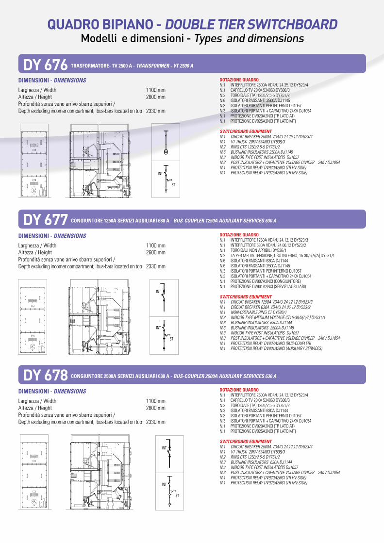
dotaZionE QuadroN.1 INTERRUTTORE 1250A VD4/U 24.12.12 DY523/3 N.1 CARRELLO TV 20KV 534863 DY508/3 N.2 TOROIDALE (TA) 1250/2,5-5 DY751/2 N.3 ISOLATORI PASSANTI 630A DJ1144 N.3 ISOLATORI PORTANTI PER INTERNO DJ1057 N.3 ISOLATORI PORTANTI + CAPACITIVO 24KV DJ1054 N.1 PROTEZIONE DV920A2NCI (TR LATO AT) N.1 PROTEZIONE DV925A2NCI (TR LATO MT)
SWItCHBOard EQUIPMEntN.1 CIRCUITBREAKER1250AVD4/U24.12.12DY523/3N.1 VTTRUCK20KV534863DY508/3N.2 RINGCTS1250/2,5-5DY751/2N.3 BUSHINGINSULATORS630ADJ1144N.3 INDOORTYPEPOSTINSULATORSDJ1057N.3 POSTINSULATORS+CAPACITIVEVOLTAGEDIVIDER24KVDJ1054N.1 PROTECTIONRELAYDV920A2NCI(TRHVSIDE)N.1 PROTECTIONRELAYDV925A2NCI(TRMVSIDE)
int
int
St
St
int
St
QUaDRO BIPIaNO - DOUBLe tIeR SWItCHBOaRDModelli e dimensioni - Types and dimensions
dimEnSioni - dIMEnSIOnS
Larghezza / Width 1100 mmAltezza / Height 2600 mmProfondità senza vano arrivo sbarre superiori / Depth excluding incomer compartment; bus-bars located on top 2330 mm
dotaZionE QuadroN.1 INTERRUTTORE 2500A VD4/U 24.25.12 DY523/4 N.1 CARRELLO TV 20KV 534863 DY508/3 N.2 TOROIDALE (TA) 1250/2,5-5 DY751/2 N.6 ISOLATORI PASSANTI 2500A DJ1145 N.3 ISOLATORI PORTANTI PER INTERNO DJ1057 N.3 ISOLATORI PORTANTI + CAPACITIVO 24KV DJ1054 N.1 PROTEZIONE DV920A2NCI (TR LATO AT) N.1 PROTEZIONE DV925A2NCI (TR LATO MT)
SWItCHBOard EQUIPMEntN.1 CIRCUITBREAKER2500AVD4/U24.25.12DY523/4N.1 VTTRUCK20KV534863DY508/3N.2 RINGCTS1250/2,5-5DY751/2N.6 BUSHINGINSULATORS2500ADJ1145N.3 INDOORTYPEPOSTINSULATORSDJ1057N.3 POSTINSULATORS+CAPACITIVEVOLTAGEDIVIDER24KVDJ1054N.1 PROTECTIONRELAYDV920A2NCI(TRHVSIDE)N.1 PROTECTIONRELAYDV925A2NCI(TRMVSIDE)
dimEnSioni - dIMEnSIOnS
Larghezza / Width 1100 mmAltezza / Height 2600 mmProfondità senza vano arrivo sbarre superiori / Depth excluding incomer compartment; bus-bars located on top 2330 mm
dotaZionE QuadroN.1 INTERRUTTORE 1250A VD4/U 24.12.12 DY523/3 N.1 INTERRUTTORE 630A VD4/U 24.06.12 DY523/2 N.1 TOROIDALI NON APRIBILI DY536/1 N.2 TA PER MEDIA TENSIONE, USO INTERNO, 15-30/5[A/A] DY531/1 N.6 ISOLATORI PASSANTI 630A DJ1144 N.6 ISOLATORI PASSANTI 2500A DJ1145 N.3 ISOLATORI PORTANTI PER INTERNO DJ1057 N.3 ISOLATORI PORTANTI + CAPACITIVO 24KV DJ1054 N.1 PROTEZIONE DV907A2NCI (CONGIUNTORE) N.1 PROTEZIONE DV901A2NCI (SERVIZI AUSILIARI)
SWItCHBOard EQUIPMEntN.1 CIRCUITBREAKER1250AVD4/U24.12.12DY523/3N.1 CIRCUITBREAKER630AVD4/U24.06.12DY523/2N.1 NON-OPENABLERINGCTDY536/1N.2 INDOORTYPEMEDIUMVOLTAGECT15-30/5[A/A]DY531/1N.6 BUSHINGINSULATORS630ADJ1144N.6 BUSHINGINSULATORS2500ADJ1145N.3 INDOORTYPEPOSTINSULATORSDJ1057N.3 POSTINSULATORS+CAPACITIVEVOLTAGEDIVIDER24KVDJ1054N.1 PROTECTIONRELAYDV907A2NCI(BUS-COUPLER)N.1 PROTECTIONRELAYDV901A2NCI(AUXILIARYSERVICES)
dimEnSioni - dIMEnSIOnS
Larghezza / Width 1100 mmAltezza / Height 2600 mmProfondità senza vano arrivo sbarre superiori / Depth excluding incomer compartment; bus-bars located on top 2330 mm
dotaZionE QuadroN.1 INTERRUTTORE 2500A VD4/U 24.12.12 DY523/4 N.1 CARRELLO TV 20KV 534863 DY508/3 N.2 TOROIDALE (TA) 1250/2,5-5 DY751/2 N.3 ISOLATORI PASSANTI 630A DJ1144 N.3 ISOLATORI PORTANTI PER INTERNO DJ1057 N.3 ISOLATORI PORTANTI + CAPACITIVO 24KV DJ1054 N.1 PROTEZIONE DV920A2NCI (TR LATO AT) N.1 PROTEZIONE DV925A2NCI (TR LATO MT)
SWItCHBOard EQUIPMEntN.1 CIRCUITBREAKER2500AVD4/U24.12.12DY523/4N.1 VTTRUCK20KV534863DY508/3N.2 RINGCTS1250/2,5-5DY751/2N.3 BUSHINGINSULATORS630ADJ1144N.3 INDOORTYPEPOSTINSULATORSDJ1057N.3 POSTINSULATORS+CAPACITIVEVOLTAGEDIVIDER24KVDJ1054N.1 PROTECTIONRELAYDV920A2NCI(TRHVSIDE)N.1 PROTECTIONRELAYDV925A2NCI(TRMVSIDE)
DY 676 traSformatorE- tV 2500 a - tranSFOrMEr - Vt 2500 a
DY 677 CongiuntorE 1250a SErViZi auSiliari 630 a - BUS-COUPLEr 1250a aUXILIary SErVICES 630 a
DY 678 CongiuntorE 2500a SErViZi auSiliari 630 a - BUS-COUPLEr 2500a aUXILIary SErVICES 630 a
int
int
St
int
int
St
int
St
QUaDRO BIPIaNO - DOUBLe tIeR SWItCHBOaRDModelli e dimensioni - Types and dimensions
dimEnSioni - dIMEnSIOnS t7 t8
Larghezza / Width 1100 mm 1100 mmAltezza / Height 2600 mm 2600 mmProfondità senza vano arrivo sbarre superiori / Depth excluding incomer compartment; bus-bars located on top 2330 mm 2330 mm
dimEnSioni - dIMEnSIOnS t7 t8
Larghezza / Width 1100 mm 1100 mmAltezza / Height 2600 mm 2600 mmProfondità senza vano arrivo sbarre superiori / Depth excluding incomer compartment; bus-bars located on top 2330 mm 2330 mm
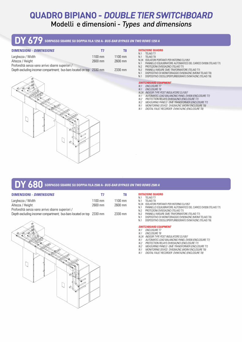
dotaZionE QuadroN.1 TELAIO T7 N.1 TELAIO T8 N.24 ISOLATORI PORTANTI PER INTERNO DJ1057 N.1 PANNELLO EQUILIBRATORE AUTOMATICO DEL CARICO DV938 (TELAIO T7) N.2 PROTEZIONI DV933A2NCI (TELAIO T7) N.2 PANNELLI MISURE GME TRAFORMATORE (TELAIO T7) N.1 DISPOSITIVO DI MONITORAGGIO DV928A2NC (MOIM TELAIO T8) N.1 DISPOSITIVO OSCILLOPERTURBOGRAFO DV947A2NC (TELAIO T8)
SWItCHBOard EQUIPMEntN.1 ENCLOSURET7N.1 ENCLOSURET8N.24 INDOORTYPEPOSTINSULATORSDJ1057N.1 AUTOMATICLOADBALANCINGPANELDV938(ENCLOSURET7)N.2 PROTECTIONRELAYSDV933A2NCI(ENCLOSURET7)N.2 MEASURINGPANELSGMETRANSFORMER(ENCLOSURET7)N.1 MONITORINGDEVICEDV928A2NC(MOIMENCLOSURET8)N.1 DIGITALFAULTRECORDERDV947A2NC(ENCLOSURET8)
DY 679 SorpaSSo SbarrE Su doppia fila 1250 a- BUS-Bar ByPaSS On tWO rOWS 1250 a
DY 680 SorpaSSo SbarrE Su doppia fila 2500 a- BUS-Bar ByPaSS On tWO rOWS 2500 a
dotaZionE QuadroN.1 TELAIO T7 N.1 TELAIO T8 N.24 ISOLATORI PORTANTI PER INTERNO DJ1057 N.1 PANNELLO EQUILIBRATORE AUTOMATICO DEL CARICO DV938 (TELAIO T7) N.2 PROTEZIONI DV933A2NCI (TELAIO T7) N.2 PANNELLI MISURE GME TRAFORMATORE (TELAIO T7) N.1 DISPOSITIVO DI MONITORAGGIO DV928A2NC (MOIM TELAIO T8) N.1 DISPOSITIVO OSCILLOPERTURBOGRAFO DV947A2NC (TELAIO T8)
SWItCHBOard EQUIPMEntN.1 ENCLOSURET7N.1 ENCLOSURET8N.24 INDOORTYPEPOSTINSULATORSDJ1057N.1 AUTOMATICLOADBALANCINGPANELDV938(ENCLOSURET7)N.2 PROTECTIONRELAYSDV933A2NCI(ENCLOSURET7)N.2 MEASURINGPANELSGMETRANSFORMER(ENCLOSURET7)N.1 MONITORINGDEVICEDV928A2NC(MOIMENCLOSURET8)N.1 DIGITALFAULTRECORDERDV947A2NC(ENCLOSURET8)
QUaDRO BIPIaNO - DOUBLe tIeR SWItCHBOaRDModelli e dimensioni - Types and dimensions
dimEnSioni - dIMEnSIOnS t7 t8
Larghezza / Width 1100 mm 1100 mmAltezza / Height 2600 mm 2600 mmProfondità senza vano arrivo sbarre superiori / Depth excluding incomer compartment; bus-bars located on top 2330 mm 2330 mm
dimEnSioni - dIMEnSIOnS t7 t8
Larghezza / Width 1100 mm 1100 mmAltezza / Height 2600 mm 2600 mmProfondità senza vano arrivo sbarre superiori / Depth excluding incomer compartment; bus-bars located on top 2330 mm 2330 mm
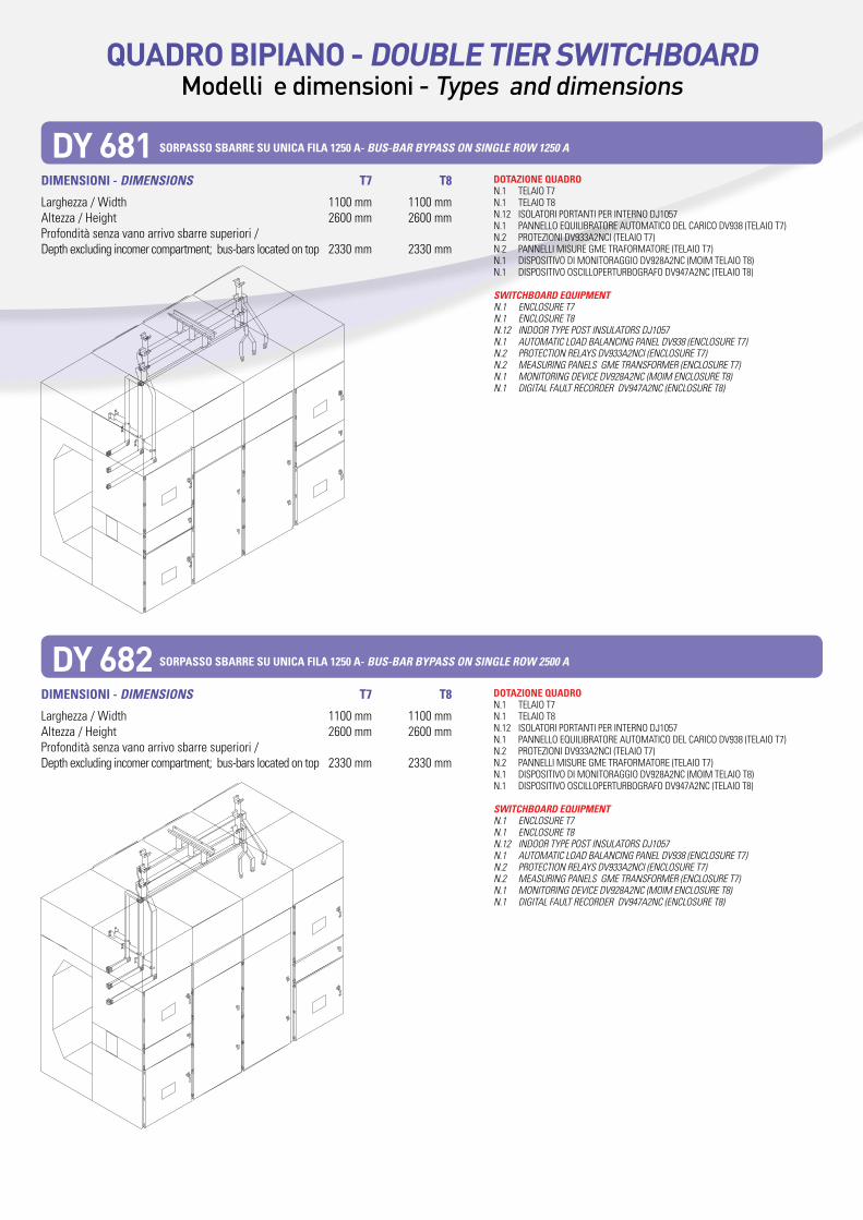
DY 681 SorpaSSo SbarrE Su uniCa fila 1250 a- BUS-Bar ByPaSS On SInGLE rOW 1250 a
DY 682 SorpaSSo SbarrE Su uniCa fila 1250 a- BUS-Bar ByPaSS On SInGLE rOW 2500 a
dotaZionE QuadroN.1 TELAIO T7 N.1 TELAIO T8 N.12 ISOLATORI PORTANTI PER INTERNO DJ1057 N.1 PANNELLO EQUILIBRATORE AUTOMATICO DEL CARICO DV938 (TELAIO T7) N.2 PROTEZIONI DV933A2NCI (TELAIO T7) N.2 PANNELLI MISURE GME TRAFORMATORE (TELAIO T7) N.1 DISPOSITIVO DI MONITORAGGIO DV928A2NC (MOIM TELAIO T8) N.1 DISPOSITIVO OSCILLOPERTURBOGRAFO DV947A2NC (TELAIO T8)
SWItCHBOard EQUIPMEntN.1 ENCLOSURET7N.1 ENCLOSURET8N.12 INDOORTYPEPOSTINSULATORSDJ1057N.1 AUTOMATICLOADBALANCINGPANELDV938(ENCLOSURET7)N.2 PROTECTIONRELAYSDV933A2NCI(ENCLOSURET7)N.2 MEASURINGPANELSGMETRANSFORMER(ENCLOSURET7)N.1 MONITORINGDEVICEDV928A2NC(MOIMENCLOSURET8)N.1 DIGITALFAULTRECORDERDV947A2NC(ENCLOSURET8)