MANUALE DI INSTALLAZIONE NOTICE D’INSTALLATION...
24
MANUALE DI INSTALLAZIONE NOTICE D’INSTALLATION INSTALLATION MANUAL MANUAL DE INSTALACION INSTALLATIONSANLEITUNG MANUAL DE INSTALAÇÃO HANDLEIDING VOOR INSTALLATIE Art. 5452
Transcript of MANUALE DI INSTALLAZIONE NOTICE D’INSTALLATION...
MANUALE DI INSTALLAZIONENOTICE D’INSTALLATIONINSTALLATION MANUAL
MANUAL DE INSTALACIONINSTALLATIONSANLEITUNGMANUAL DE INSTALAÇÃO
HANDLEIDING VOOR INSTALLATIE
Art. 5452

MANUALE DI INSTALLAZIONE
NOTICE D’INSTALLATION
INSTALLATION MANUAL
MANUAL DE INSTALACION
INSTALLATIONSANLEITUNG
MANUAL DE INSTALAÇÃO
HANDLEIDING VOOR INSTALLATIE
I
F
GB
E
D
P
NL
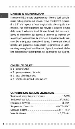
MODALITA’ DI FUNZIONAMENTO Il sensore 5452 è stato progettato per rilevare ogni cambia-mento della posizione del veicolo. Rileva spostamenti superio-ri a 1.8° sia rispetto all’asse longitudinale che a quello tra-sversale. Può essere utilizzato per rilevare il tentativo di furtodelle ruote, il sollevamento ed il traino del veicolo.Il sensore siattiva all’inserimento del sistema di allarme ed impiega 90secondi per memorizzare la posizione di riferimento del vei-colo. Durante questo intervallo di tempo i movimenti rilevatirispetto alla posizione memorizzata origineranno un allar-me.Vengono registrati cambiamenti di posizione sia veloci chelenti con opportuni accorgimenti tali da evitare i falsi allarmi.
CONTENUTO DEL KIT n. 1 sensore 5452n. 1 spezzone nastro biadesivon. 1 cavo di collegamenton. 1 libretto istruzioni di installazione
CARATTERISTICHE TECNICHE DEL SENSORE Tensione di alimentazione nominale...........................12VDCTensione di esercizio.............................................9/16VDCConsumo a 12 VDC................................................<4.6mATemperatura d’esercizio.................................. -40C°/+85C°Soglia di allarme..............................................1.8°+/- 0.4°Velocità rilevate.................................................> 0,6°/min.
I
F
GB
E
D
P
NL
1
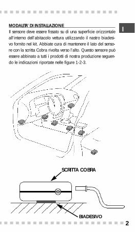
MODALITA’ DI INSTALLAZIONE Il sensore deve essere fissato su di una superficie orizzontaleall'interno dell'abitacolo vettura utilizzando il nastro biadesi-vo fornito nel kit. Abbiate cura di mantenere il lato del senso-re con la scritta Cobra rivolta verso l’alto. Questo sensore puòessere abbinato a tutti i prodotti di nostra produzione seguen-do le indicazioni riportate nelle figure 1-2-3.
SCRITTA COBRA
BIADESIVO
I
F
GB
E
D
P
NL
2
I
F
GB
E
D
P
NL
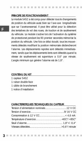
PRINCIPE DE FONCTIONNEMENT Le module 5452 a ést conçu pour détecter tous le changementsde position du véhicule aussi bien sur l’axe axe longitudinaleque sur l’axetransversal. Il peut être utilisé pour la détectiondes tentatives de vol des roues, de traction et de soulèvementdu véhicule. Le module s’active lors de l’activation du systèmede protectionet pendant les 90 premier secondes mémorise laposition du véhicule. Une fois ce délai écoulé, tous les mouve -ments détectés modifiant la position mémorisée déclencherontl’alarme. Les déplacements rapides sont détectés immediata-ment, tandis que les déplacements lents sont détectés quand lavitesse de soulèvement est superiéure a 0,6° par minute.L’angle minimum qui génère l’alarme est de 1,8°.
CONTENU DU KIT 1 capteur 54521 ruban double-face1 câble de branchement1 notice d’installation
CARACTERISTIQUES TECHNIQUES DU CAPTEUR Tension d’alimentation nominale..............................12 V CCTension d’exercice...............................................9/16 V CCConsommation à 12 V CC....................................< 4,6 mATempérature d’exercice....................................-40C°/+85C°Seuil d’alarme.................................................. 1,8°+/-0,4°Vitesses détectées............................................>0,6°/minute
3
I
F
GB
E
D
P
NL
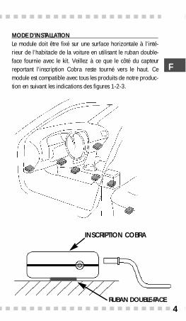
MODE D’INSTALLATION Le module doit être fixé sur une surface horizontale à l’inté-rieur de l’habitacle de la voiture en utilisant le ruban double-face fournie avec le kit. Veillez à ce que le côté du capteurreportant l’inscription Cobra reste tourné vers le haut. Cemodule est compatible avec tous les produits de notre produc-tion en suivant les indications des figures 1-2-3.
INSCRIPTION COBRA
RUBAN DOUBLE-FA C E4
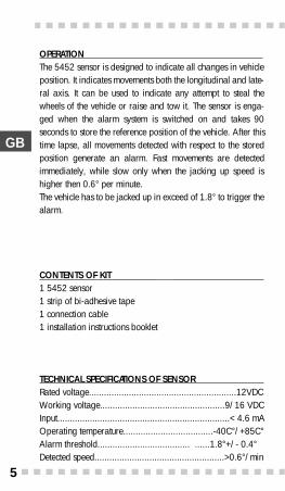
OPERATION The 5452 sensor is designed to indicate all changes in vehicleposition. It indicates movements both the longitudinal and late-ral axis. It can be used to indicate any attempt to steal thewheels of the vehicle or raise and tow it. The sensor is enga-ged when the alarm system is switched on and takes 90seconds to store the reference position of the vehicle. After thistime lapse, all movements detected with respect to the storedposition generate an alarm. Fast movements are detectedimmediately, while slow only when the jacking up speed ishigher then 0.6° per minute. The vehicle has to be jacked up in exceed of 1.8° to trigger thealarm.
CONTENTS OF KIT 1 5452 sensor1 strip of bi-adhesive tape1 connection cable1 installation instructions booklet
TECHNICAL SPECIFICATIONS OF SENSORRated voltage...........................................................12VDCWorking voltage..................................................9/16 VDCInput.....................................................................< 4.6 mAOperating temperature....................................-40C°/+85C°Alarm threshold..................................... ......1.8°+/- 0.4°Detected speed....................................................>0.6°/min
I
F
GB
E
D
P
NL
5
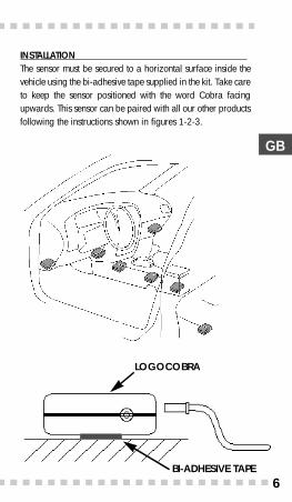
INSTALLATION The sensor must be secured to a horizontal surface inside thevehicle using the bi-adhesive tape supplied in the kit. Take careto keep the sensor positioned with the word Cobra facingupwards. This sensor can be paired with all our other productsfollowing the instructions shown in figures 1-2-3.
LOGOCOBRA
BI-ADHESIVE TAPE
I
F
GB
E
D
P
NL
6
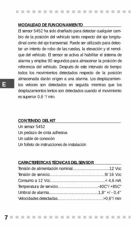
MODALIDAD DE FUNCIONAMIENTO El sensor 5452 ha sido diseñado para detectar cualquier cam-bio de la posición del vehículo tanto respecto del eje longitu-dinal como del eje transversal. Puede ser utilizado para detec-tar un intento de robo de las ruedas, la elevación y el remol-que del vehículo. El sensor se activa al habilitar el sistema dealarma y emplea 90 segundos para almacenar la posición dereferencia del vehículo. Después de este intervalo de tiempotodos los movimientos detectados respecto de la posiciónalmacenada darán origen a una alarma. Los desplazamien-tos veloces son detectados en seguida mientras que losdesplazamientos lentos son detectados cuando el movimientoes superior 0,6 °/min.
CONTENIDO DEL KIT Un sensor 5452Un pedazo de cinta adhesivaUn cable de conexiónUn folleto de instrucciones de instalación
CARACTERÍSTICAS TÉCNICAS DEL SENSOR Tensión de alimentación nominal................................12 VccTensión de servicio................................................9/16 VccConsumo a 12 Vcc................................................< 4,6 mATemperatura de servicio...................................-40C°/+85C°Umbral de alarma...........................................1,8° +/- 0,4°Velocidades detectadas........................................>0,6°/min
7
I
F
GB
E
D
P
NL
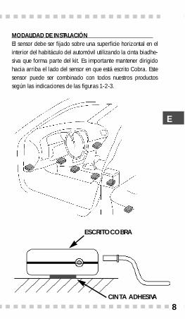
MODALIDAD DE INSTALACIÓN El sensor debe ser fijado sobre una superficie horizontal en elinterior del habitáculo del automóvil utilizando la cinta biadhe-siva que forma parte del kit. Es importante mantener dirigidohacia arriba el lado del sensor en que está escrito Cobra. Estesensor puede ser combinado con todos nuestros pro d u c t o ssegún las indicaciones de las figuras 1-2-3.
ESCRITOCOBRA
CINTA ADHESIVA
8
I
F
GB
E
D
P
NL
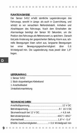
FUNKTIONSWEISE Der Sensor 5452 erfaßt sämtliche Lageänderungen desFahrzeugs, sowohl in Längs- als auch in Querrichtung, undschützt so vor versuchtem Reifendiebstahl, Anheben undAbschleppen des Fahrzeugs. Nach dem Einschalten derAlarmanlage benötigt der Sensor 90 Sekunden, um diePosition des Fahrzeugs als Referenzwert zu speichern. Danachlöst jede Änderung der gespeicherten Stellung Alarm aus, sch-nelle Bewegungen lösen sofort aus, langsame Bewegungenbei einer Bewegungsgeschwindigkeit über 0,6Winkelgrad/min. Die Lageänderung muss jeweil über 1,8°liegen.
LIEFERUMFANG 1 Sensor 54521 Stück doppelseitiges Klebeband1 Anschlußkabel1Installationsanleitung
TECHNISCHE DATEN Anschlußspannung.................................................12 V DCBetriebsspannung..............................................9 / 16 V DCStromverbrauch bei 12 V DC................................< 4,6 mAB e t r i e b s t e m p e r a t u r. . . . . . . . . . . . . . . . . . . . . . . . . . . . . . . . . . . . - 4 0 C ° / + 8 5 C °Alarmschwell...................................................1,8°+/- 0,4°Erfaßte Geschwindigkeiten.................> 0,6 Winkelgrad/min
9
I
F
GB
E
D
P
NL
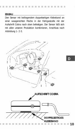
EINBAU Den Sensor mit beiliegendem doppelseitigen Klebeband aneiner waagerechten Fläche in der Fahrgastzelle mit derAufschrift Cobra nach oben befestigen. Der Sensor läßt sichmit allen unseren Produktion kombinieren, Anschluss nachAbbildung 1- 2-3.
AUFSCHRIFT COBRA
10
DOPPELSEITIGES KLEBEBAND
I
F
GB
E
D
P
NL
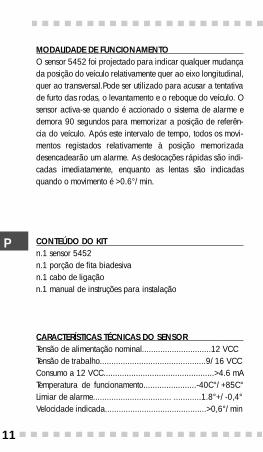
MODALIDADE DE FUNCIONAMENTO O sensor 5452 foi projectado para indicar qualquer mudançada posição do veículo relativamente quer ao eixo longitudinal,quer ao transversal.Pode ser utilizado para acusar a tentativade furto das rodas, o levantamento e o reboque do veículo. Osensor activa-se quando é accionado o sistema de alarme edemora 90 segundos para memorizar a posição de referên-cia do veículo. Após este intervalo de tempo, todos os movi-mentos registados relativamente à posição memorizadadesencadearão um alarme. As deslocações rápidas são indi-cadas imediatamente, enquanto as lentas são indicadasquando o movimento é >0.6°/min.
CONTEÚDO DO KIT n.1 sensor 5452n.1 porção de fita biadesivan.1 cabo de ligaçãon.1 manual de instruções para instalação
CARACTERÍSTICAS TÉCNICAS DO SENSOR Tensão de alimentação nominal..............................12 VCCTensão de trabalho..............................................9/16 VCCConsumo a 12 VCC................................................>4.6 mATemperatura de funcionamento.......................-40C°/+85C°Limiar de alarme.................................. ............1.8°+/-0,4°Velocidade indicada............................................>0,6°/min
I
F
GB
E
D
P
NL
11
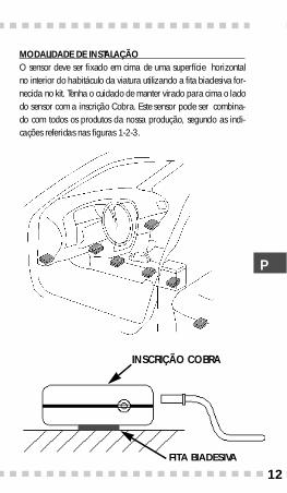
MODALIDADE DE INSTALAÇÃO O sensor deve ser fixado em cima de uma superfície horizontalno interior do habitáculo da viatura utilizando a fita biadesiva for-necida no kit. Tenha o cuidado de manter virado para cima o ladodo sensor com a inscrição Cobra. Este sensor pode ser combina-do com todos os produtos da nossa produção, segundo as indi-cações referidas nas figuras 1-2-3.
INSCRIÇÃO COBRA
FITA BIADESIVA
I
F
GB
E
D
P
NL
12
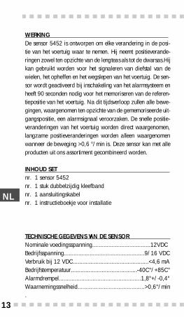
WERKING De sensor 5452 is ontworpen om elke verandering in de posi-tie van het voertuig waar te nemen. Hij neemt positieverande-ringen zowel ten opzichte van de lengteas als tot de dwarsas.Hijkan gebruikt worden voor het signaleren van diefstal van dewielen, het opheffen en het wegslepen van het voertuig. De sen-sor wordt geactiveerd bij inschakeling van het alarmsysteem enheeft 90 seconden nodig voor het memoriseren van de re f e re n-tiepositie van het voertuig. Na dit tijdsverloop zullen alle bewe-gingen, waargenomen ten opzichte van de gememoriseerde uit-gangspositie, een alarmsignaal vero o rzaken. De snelle positie-veranderingen van het voertuig worden direct waarg e n o m e n ,langzame positieveranderingen worden alleen waarg e n o m e nwanneer de beweging >0,6 °/min is. Deze sensor kan met allep roducten uit ons assortiment gecombineerd word e n .
INHOUD SET nr. 1 sensor 5452nr. 1 stuk dubbelzijdig kleefband nr. 1 aansluitingskabelnr. 1 instructieboekje voor installatie
TECHNISCHE GEGEVENS VAN DE SENSOR Nominale voedingsspanning....................................12VDCBedrijfsspanning..................................................9/16 VDCVerbruik bij 12 VDC...............................................<4,6 mAB e d r i j f s t e m p e r a t u u r. . . . . . . . . . . . . . . . . . . . . . . . . . . . . . . . . . . . . . ...- 4 0 C ° / + 8 5 C °Alarmdrempel...................................................1,8°+/-0,4°Wa a rn e m i n g s s n e l h e i d . . . . . . . . . . . . . . . . . . . . . . . . . . . . . . . . . . . . . . . . . > 0 , 6 ° / m i n.
I
F
GB
E
D
P
NL
13
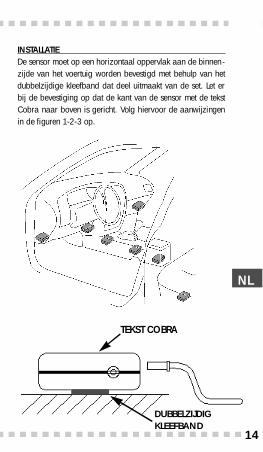
INSTALLATIE De sensor moet op een horizontaal oppervlak aan de binnen-zijde van het voertuig worden bevestigd met behulp van hetdubbelzijdige kleefband dat deel uitmaakt van de set. Let erbij de bevestiging op dat de kant van de sensor met de tekstCobra naar boven is gericht. Volg hiervoor de aanwijzingenin de figuren 1-2-3 op.
TEKST COBRA
I
F
GB
E
D
P
NL
I
F
GB
E
D
P
NL
DUBBELZIJDIG KLEEFBAND
14
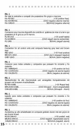
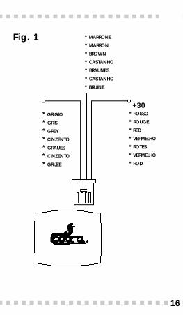
FIG. 1 Per tutte le centraline e compatti che possiedono filo grigio e marrone.Filo ROSSO........................................................................(+30 positivo fisso)Filo MARRONE................................................(GND negativo allarme inserito)Filo GRIGIO..........................................................SEGNALE (negativo allarme)
FIG. 1 Connexion pour tous les dispositifs de contrôle et systèmes de mise à la terre quipossèdent un fil gris ou un fil marron.FIL ROUGE …..............................................................…….(+30 positif stable)FIL MARRON …...........................…....……...(GND négatif alarme enclenchée)FIL GRIS ………............................................………....SIGNAL (négatif alarme)
FIG. 1 Connection for all control units and compacts featuring grey lead and brownlead.RED LEAD ..........................................................................(+30 fixed positive)BROWN LEAD..................................................(GND alarm engaged negative)GREY LEAD................................................................SIGNAL (alarm negative)
FIG. 1 Conexion para todas unitades y compactos que possuem fio cinzento y fiocastanho.FIO VERMELHO...............................................................(+30 positivo de fixo)FIO CASTANHO............................................(GND negativo de alarme ligado)FIO CINZENTO......................................................SINAL (negativo de alarme)
FIG. 1 Steckverbinder für alle Alarmmodule und versiegelten Kompaktmodule mitgrauem und braunem Anschlußkabel.ROTES KABEL ……………..................................................…(+30 Pluspol fest)BRAUNES KABEL …….........…….........…(GND Minuspol - Alarm eingeschaltet)GRAUES KABEL ………...............................……….SIGNAL (Minuspol - Alarm)
FIG. 1 Ligação para todas unidades e compactos que possuem fio cinzento e fiocastanho.FIO VERMELHO …………….........................................…(+30 positivo do fixo)FIO CASTANHO ….........…………....….........(GND negativo do alarme ligado)FIO CINZENTO..........................…....……..……… SINAL (negativo do alarme)
FIG. 1 Aansluiting op alle schakelkasten en compacte gesloten dozen met een grijze eneen bruine draad.RODE DRAAD ……………..............................................…..(+30 positief, vast)BRUINE DRAAD.....................…………......(GND negatief, ingeschakeld alarm)GRIJZE DRAAD ………….................................……SIGNAAL (negatief, alarm)
15
+30* ROSSO
* ROUGE
* RED
* VERMELHO
* ROTES
* VERMELHO
* ROD
Fig. 1 * MARRONE
* MARRON
* BROWN
* CASTANHO
* BRAUNES
* CASTANHO
* BRUINE
* GRIGIO
* GRIS
* GREY
* CINZENTO
* GRAUES
* CINZENTO
* GRIJZE
16
FIG. 2 Per tutti i compatti senza U.S.interni.
FIG. 2 Connexion pour tous les systèmes de mise à la terre sans U.S. à l’intérieur.
FIG. 2 Connection for all compacts without built in U.S.
FIG. 2 Conexion para todas y compactos sem U.S. interno.
FIG. 2 Anschluß der Kompaktmodule ohne internen U.S.
FIG. 2 Ligação para todos os compactos sem U.S. interno.
FIG. 2 Aansluiting op alle compacte gesloten dozen zonder U.S binnenin.
17
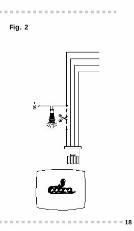
Fig. 2
18
FIG. 3 Per tutte le centraline con connettore di tipo telefonico.
FIG. 3 Connexion pour tous les dispositifs de contrôle avec connecteur de type fixe.
FIG. 3 Connection for all control units with phone type jack.
FIG. 3 Conexion para todas las unitades con conector tipo telefónico.
FIG. 3 Anschluß der Alarmmodule mit Western-Modular-Steckverbinder.
FIG. 3 Ligação para todos as unidades com conector tipo telefónico.
FIG. 3 Aansluiting op alle schakelkasten met een connector van het telefoontype.
19
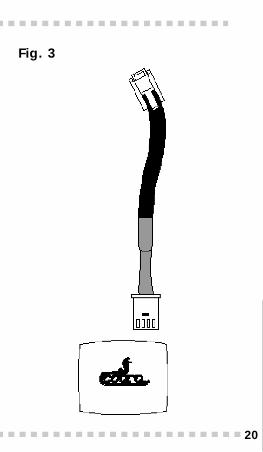
Fig. 3
20
Approvato in accordo alla Direttiva Europea 95/56/ECdel 8 Novembre ‘95 ealla Direttiva Europea 95/54/ECdel 31 Ottobre ’95.
Certifié conformément à la Directive européenne 95/56/CEE du 8 novembre1995 et à la Directive européenne 95/54/CEE du 31 octobre 1995.
Approved in agreement with European Directive 95/56/EC dated 8 November1995 and European Directive 95/54/EC dated 31 October 1995.
Approvado en conformitade con la Directiva Europeia 95/56/CE de 8deNovembro de 1995 y con la Directiva Europeia 95/54/CEde 31de Outubro de 1995.
Das Gerät erfüllt die Vorschriften der EG-Richtlinien 95/56/EWG vom 8.November 1995 und 95/54/EWG vom 31. Oktober 1995.
Aprovado em conformidade com a Directiva Europeia 95/56/CE de 8 deNovembro de 1995 e com a Directiva Europeia 95/54/CE de 31 de Outubro de1995.
Goedgekeurd in overeenstemming met de Europese richtlijn 95/46/CE van 8november 1995 en de Europese richtlijn 95/54/CE van 31 oktober 1995.
DEL TA ELETTRONICA SP AVia A s t i c o, 41 - 21100 VA R E S E( I TA LY )
Timbro del Concessionario/ Cahcet du ConcessionarieDealer Stamp /Stempel Dealer
Sello del concesionario/ Händler-StempelTimbro del concessionario/ Carimbo do concessionario