I LIBRETTO ISTRUZIONI PALI SERIE ALKES - neri.biz · pali serie alkes instruction booklet of series...
20
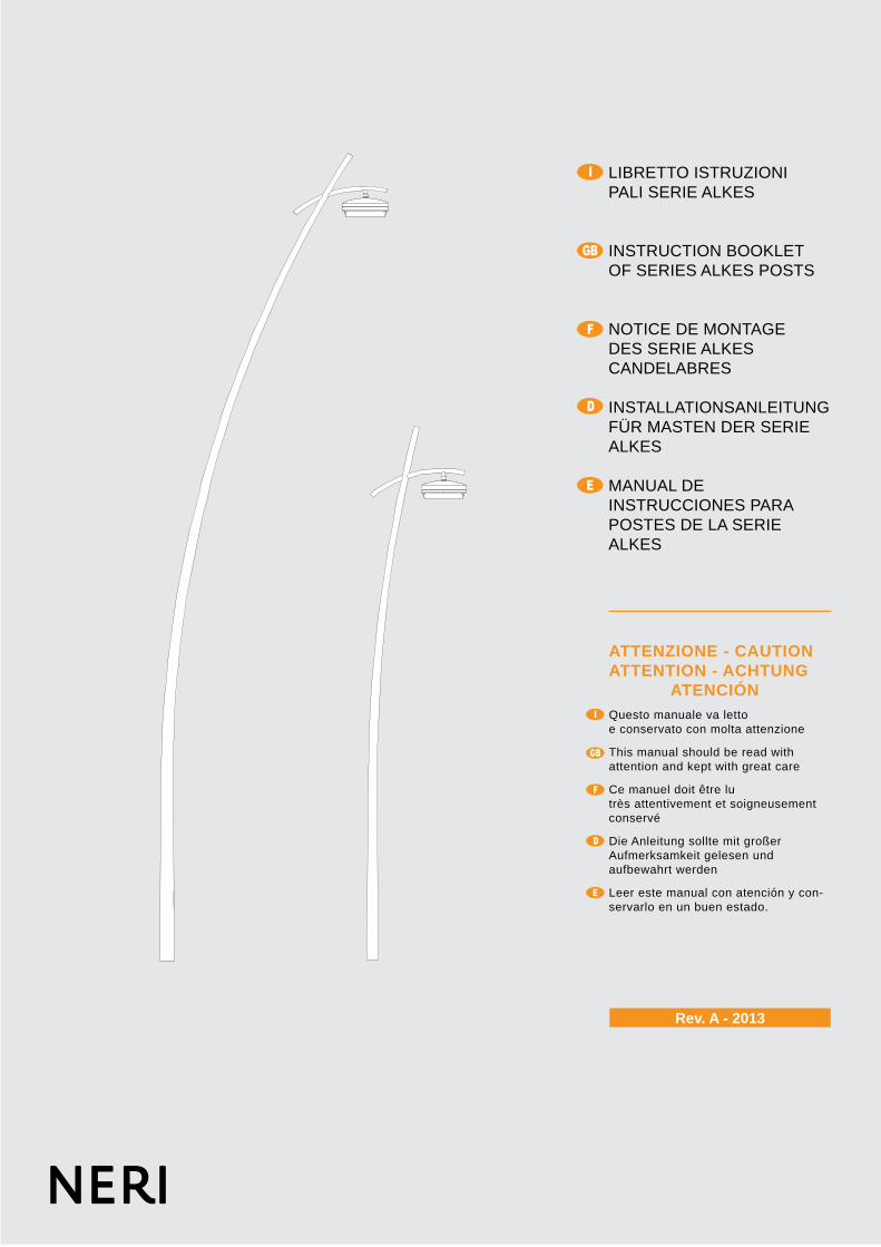
Rev. A - 2013 I GB F D E I GB F D E ATTENZIONE - CAUTION ATTENTION - ACHTUNG ATENCIÓN Questo manuale va letto e conservato con molta attenzione This manual should be read with attention and kept with great care Ce manuel doit être lu très attentivement et soigneusement conservé Die Anleitung sollte mit großer Aufmerksamkeit gelesen und aufbewahrt werden Leer este manual con atención y con- servarlo en un buen estado. LIBRETTO ISTRUZIONI PALI SERIE ALKES INSTRUCTION BOOKLET OF SERIES ALKES POSTS NOTICE DE MONTAGE DES SERIE ALKES CANDELABRES INSTALLATIONSANLEITUNG FÜR MASTEN DER SERIE ALKES MANUAL DE INSTRUCCIONES PARA POSTES DE LA SERIE ALKES
Transcript of I LIBRETTO ISTRUZIONI PALI SERIE ALKES - neri.biz · pali serie alkes instruction booklet of series...
Rev. A - 2013
I
GB
F
D
E
I
GB
F
D
E
ATTENZIONE - CAUTIONATTENTION - ACHTUNG ATENCIÓNQuesto manuale va lettoe conservato con molta attenzione
This manual should be read withattention and kept with great care
Ce manuel doit être lu très attentivement et soigneusement conservé
Die Anleitung sollte mit großerAufmerksamkeit gelesen undaufbewahrt werden
Leer este manual con atención y con-servarlo en un buen estado.
LIBRETTO ISTRUZIONIPALI SERIE ALKES
INSTRUCTION BOOKLETOF SERIES ALKES POSTS
NOTICE DE MONTAGE DES SERIE ALKES CANDELABRES
INSTALLATIONSANLEITUNGFÜR MASTEN DER SERIE ALKES
MANUAL DE INSTRUCCIONES PARA POSTES DE LA SERIE ALKES

2
NERI S.p.A.S.S. EMILIA 1622 - 47020 LONGIANO (FC) - ITALY
Tel. +39 0547 652111 Fax +39 0547 54074 www.neri.biz - [email protected]
Certificato/Certificate 9105.DONE
ISO 9001:2008
Certificato/Certificate9191.NER1
ISO 14001:2001
Ogni riproduzione ed utilizzo per fini propri di questo manuale non è consentita. Tutti i diritti sono riservati.E’ vietata la riproduzione anche parziale di esso senza il consenso scritto della Neri spa.
La Neri spa si riserva il diritto di apportare modifiche ai propri prodotti e alla documentazione senza obbligo di preavviso.
Any reproduction and use for its own purposes of this manual is not permitted. All rights reserved.Reproduction of this manual, even partially, is forbidden without written consent from Neri spa.
Neri spa reserves the right to modify its products and documentation without obligation to give prior warning.
Toute reproduction et utilisation pour ses propres fins de ce manuel n’est pas autorisée. Tous droits réservés.Ce manuel ne peut être reproduit, même partiellement, sans l’accord écrit de Neri spa.
Neri spa se réserve le droit d’apporter toutes modifications à ses produits et à la documentation sans préavis.
Eine Vervielfältigung und Nutzung für den eigenen Zweck dieses Handbuches ist nicht gestattet. Alle Rechte vorbehalten.Seine - auch auszugsweise - Reproduktion ohne schriftliche Zustimmung der Neri spa ist verboten.
Die Neri spa behält sich das Recht vor, an ihren Produkten und der Dokumentation Veränderungen vorzunehmen,ohne dies vorher ankündigen zu müssen.
Cualquier reproducción y uso para sus propios fines de este manual no está permitido. Todos los derechos reservados.Se prohíbe su reproducción incluso parcial sin autorización por escrito de la empresa Neri spa.
Neri spa se reserva el derecho de aportar cambios a sus productos y a la documentación sin obligación de aviso previo.
Autori: Isacco Neri - Titolo: Libretto Istruzioni Pali “ALKES” - Pubblicatore: Neri spaProgetto e coordinamento grafico: Daniele Lombardi - Stampa: Grafiche MDM srl, Forlì FC, Luglio 2013.
Tutti i diritti riservati. E’ fatto espresso divieto a qualunque riproduzione parziale o totale del presente testo.DESIGN PATENTED, PRINTED IN ITALY

3
www.neri.biz
I
I
I
I
I
I
I
GB
GB
GB
GB
GB
GB
GB
F
F
F
F
F
F
F
D
D
D
D
D
D
D
E
E
E
E
E
E
E
SIMBOLI E ETICHETTA SYMBOLS AND LABELSYMBOLES ET ETIQUETTESYMBOLE UND AUFKLEBERSÍMBOLOS Y ETIQUETAS
1°pag 4
NOTE GENERALI ALLA CONSEGNA GENERAL NOTES ON DELIVERYCONSIGNES GÉNÉRALES À LA LIVRAISON ALLGEMEINE HINWEISE BEI DER LIEFERUNGNOTAS GENERALES DE ENTREGA
2°pag 5
PRESCRIZIONI DI SICUREZZA SAFETY PRECAUTIONS PRESCRIPTIONS DE SECURITE SICHERHEITSVORSCHRIFTEN NORMAS DE SEGURIDAD
3°pag 6
DISIMBALLO ANIME PALIUNPACKING POST CORESDEBALLAGE AMES DE CANDELABREAUSPACKEN DIE KERNMASTENDESEMBALAJE DE ALMAS PARA POSTES
4°pag 7
SISTEMA DI FISSAGGIO - MURATURAFIXING SYSTEM - CEMENTING INSYSTEME D’ANCRAGE - SCELLEMENT DIRECTBEFESTIGUNGSSYSTEM – EINMAUERNSISTEMA DE FIJACIÓN-MURAL
5°pag 8
SISTEMA DI FISSAGGIO - FLANGIAFIXING SYSTEM - FLANGESYSTEME D’ANCRAGE - SEMELLE DE FIXATIONBEFESTIGUNGSSYSTEM – FLANSCHSISTEMAS DE FIJACIÓN-BRIDA
6°pag 9
INSTALLAZIONE GUAINA PROTETTIVAFITTING OF PROTECTIVE SHEATHINSTALLATION GAINE DE PROTECTIONINSTALLATION DES SCHUTZMANTELSINSTALACIÓN DE FUNDA PROTECTORA
7°pag 10-11
IGBFDE
PLINTO DI FONDAZIONEFOUNDATION PLINTHMASSIF D’ANCRAGEFUNDAMENTSOCKELPLINTO DE CIMENTACIÓN
8°pag 12
IGBFDE
IMBRACATURA PALOPOLE SLINGINGÉLINGAGE CANDÉLABREANSCHLAG - LICHTMASTESLINGADO DEL POSTE
9°pag 13
IGBFDE
MESSA A TERRRAGROUND CONNECTIONMISE A LA TERREERDUNGPUESTA A TIERRA
11°pag 17
IGBFDE
INSTALLAZIONE ANIME PALIINSTALLATION POST CORESINSTALLATION DES AMES DE CANDELABREINSTALLATION FÜR DIE KERNMASTENINSTALACIÓN DE ALMAS PARA POSTES
10°pag 14-16
IGBFDE
I PROTEZIONI FINALIFINAL PROTECTIONPROTECTIONS FINALESSCHUTZBEHANDLUNGPROTECCIÓN FINAL
12°pag 17
GBFDE
ASSEMBLAGGIO APPARECCHI SOSPESIASSEMBLING SUSPENDED EQUIPMENTASSEMBLAGE DISPOSITIFS SUSPENDUSZUSAMMENBAU HÄNGENDE GERÄTEENSAMBLAJE APARATOS SUSPENDIDOS
13°pag 19
IGBFDE
CONTROLLI FINALI E MANUTENZIONEFINAL CHECKS AND MAINTENANCECONTRÔLES FINALS ET ENTRETIENENDKONTROLLEN UND WARTUNGCONTROLES FINALES Y MANTENIMIENTO
14°pag 20
INDICE - CONTENTS - INDEX - INHALTVERZEICHNIS - INDICE
4
CODICE - CODE
0001.209.850DESCRIZIONE - DESCRIPTION
PALOPOST
I
GB
F
D
E
I
I
GB
GB
F
F
D
D
E
E
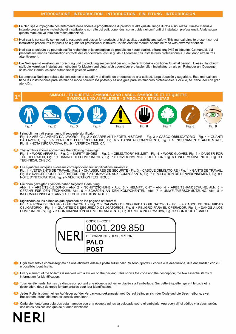
I simboli mostrati sopra hanno il seguente significato: Fig. 1 > ABBIGLIAMENTO DA LAVORO - Fig. 2 > SCARPE ANTINFORTUNISTICHE - Fig. 3 > CASCO OBBLIGATORIO - Fig. 4 > GUANTI DA LAVORO, Fig. 5 > PERICOLO PER L’OPERATORE, Fig. 6 > DANNI AI COMPONENTI, Fig. 7 > INQUINAMENTO AMBIENTALE, Fig. 8 > NOTA INFORMATIVA, Fig. 9 > VERIFICA TECNICA.
The symbols shown above have the following meanings:Fig. 1 > WORK APPAREL - Fig. 2 > SAFETY SHOES - Fig. 3 > OBLIGATORY HELMET - Fig. 4 > WORK GLOVES, Fig. 5 > DANGER FOR THE OPERATOR, Fig. 6 > DAMAGE TO COMPONENTS, Fig. 7 > ENVIRONMENTAL POLLUTION, Fig. 8 > INFORMATIVE NOTE, Fig. 9 > TECHNICAL CHECK.
Les symboles indiqués ci-dessus correspondent aux significations suivantes:Fig. 1 > VÊTEMENTS DE TRAVAIL - Fig. 2 > CHAUSSURES DE SÉCURITÉ - Fig. 3 > CASQUE OBLIGATOIRE - Fig. 4 > GANTS DE TRAVAIL, Fig. 5 > DANGER POUR L’OPÉRATEUR, Fig. 6 > DOMMAGES AUX COMPOSANTS, Fig. 7 > POLLUTION DE L’ENVIRONNEMENT, Fig. 8 > NOTE D’INFORMATION, Fig. 9 > VÉRIFICATION TECHNIQUE.
Die oben gezeigten Symbole haben folgende Bedeutung:Abb. 1 > ARBEITSKLEIDUNG - Abb. 2 > SCHUTZSCHUHE - Abb. 3 > HELMPFLICHT - Abb. 4 > ARBEITSHANDSCHUHE, Abb. 5 >GEFAHR FÜR DEN TECHNIKER, Abb. 6 > SCHÄDEN AN DEN KOMPONENTEN, Abb. 7 > UMWELTVERSCHMUTZUNG, Abb. 8 > INFORMATIONSBLATT, Abb. 9 > TECHNISCHE KONTROLLE.
Significado de los símbolos que aparecen en las páginas anteriores: Fig. 1 > ROPA DE TRABAJO OBLIGATORIA - Fig. 2 > CALZADO DE SEGURIDAD OBLIGATORIO - Fig. 3 > CASCO DE SEGURIDAD OBLIGATORIO - Fig. 4 > GUANTES DE SEGURIDAD OBLIGATORIOS, Fig. 5 > PELIGRO PARA EL OPERADOR, Fig. 6 > DAÑOS A LOS COMPONENTES, Fig. 7 > CONTAMINACIÓN DEL MEDIO AMBIENTE, Fig. 8 > NOTA INFORMATIVA, Fig. 9 > CONTROL TÉCNICO.
La Neri spa è impegnata costantemente nella ricerca e progettazione di prodotti di alta qualità, lunga durata e sicurezza. Questo manuale intende presentare le metodiche di installazione corrette dei pali, ponendosi come guida nei confronti di installatori professionali. A tale scopo questo manuale va letto con molta attenzione.
Neri spa is constantly committed to research and design for products of high quality, durability and safety. This manual aims to present correct installation procedures for posts as a guide for professional installers. To this end the manual should be read with extreme attention.
Neri spa a toujours eu pour objectif la recherche et la conception de produits de haute qualité, offrant longévité et sécurité. Ce manuel, qui présente les modes d’installation corrects des candélabres, est un guide à l’adresse des installateurs professionnels. Il doit donc être lu très attentivement.
Die Neri spa ist konstant um Forschung und Entwicklung zeitbeständiger und sicherer Produkte von hoher Qualität bemüht. Dieses Handbuch stellt die korrekten Installationsmethoden für Masten und bietet sich gegenüber professionellen Installateuren als ein Ratgeber an. Deswegen sollte dies Handbuch sehr aufmerksam gelesen werden.
La empresa Neri spa trabaja de continuo en el estudio y el diseño de productos de alta calidad, larga duración y seguridad. Este manual con-tiene las instrucciones para instalar de modo correcto los postes y es una guía para instaladores profesionales. Por ello, se debe leer con gran atención.
Ogni elemento è contrassegnato da una etichetta adesiva posta sull’imballo. Vi sono riportati il codice e la descrizione, due dati basilari con cui è possibile identificarlo.
Every element of the bollards is marked with a sticker on the packing. This shows the code and the description, the two essential items of information for identification.
Tous les éléments bornes de dissuasion portent une étiquette adhésive placée sur l’emballage. Sur cette étiquette figurent le code et la description, deux données fondamentales pour leur identification.
Jedes Poller ist durch einen Aufkleber auf der Verpackung gekennzeichnet. Darauf befinden sich der Code und die Beschreibung, zwei Basisdaten, durch die man es identifizieren kann.
Cada elemento para bolardos está marcado con una etiqueta adhesiva colocada sobre el embalaje. Aparecen allí el código y la descripción, dos datos básicos con que se pueden identificar.
Fig. 1 Fig. 2 Fig. 3 Fig. 4 Fig. 5 Fig. 6 Fig. 7 Fig. 8 Fig. 9
INTRODUZIONE - INTRODUCTION - INTRODUCTION - EINLEITUNG - INTRODUCCIÓN
1° SIMBOLI / ETICHETTA - SYMBOLS AND LABEL- SYMBOLES ET ETIQUETTESYMBOLE UND AUFKLEBER - SÍMBOLOS Y ETIQUETAS

5
www.neri.biz
3°
A C
B
I
GB
F
D
E
Gli elementi dei pali possono esere spediti e consegnati in vari modi: A) elementi singoli sfusi; B) elementi raggruppati su bancale in legno; C) elementi raggruppati in casse di legno su bancale.L’imballo dei singoli elementi può essere realizzato con cartone in vari strati, scatole di cartone, sacchetti di nylon.In ogni caso comunque al ricevimento della merce controllare che: 1) l’imballo sia integro; 2) la fornitura corrisponda all’ordine (vedi bolla di consegna); 3) non vi siano parti mancanti.
In caso di danni o parti mancanti, informare immediatamente e in modo dettagliato (e/o con foto) la Neri spa.
The elements of the posts can be shipped and delivered in various ways:A) loose single elements; B) elements packed together on wooden pallet; C) elements packed together in wooden crates on pallet.The single elements can be packed with several layers of cardboard, cardboard boxes and plastic bags.On receipt of the goods, always:1) check that packing is undamaged; 2) check that goods received correspond to order (consult delivery note); 3) check that there are no missing parts.
In case of damage or missing parts, immediately inform Neri spa, giving full details (and/or with photograph).
Les éléments des candélabres peuvent être expédiés et livrés de différentes façons:A) éléments seuls en vrac; B) éléments groupés sur palette en bois; C) éléments groupés dans des caisses en bois sur palette. L’emballage de chaque élément peut être réalisé dans des feuilles de carton, des boîtes en carton, des sacs en nylon.Dans tous les cas, s’assurer dès la réception de la marchandise que:1) l’emballage soit intact; 2) la fourniture corresponde à la commande (voir bulletin de livraison); 3) il ne manque aucune partie.
En cas de dommages ou de parties manquantes, en informer immédiatement d’une manière détaillée (et/ou avec photo) Neri spa.
Die Gusseisenelemente der Pfähle können auf verschiedene Weise transportiert und angeliefert werden:A) einzelne Elemente; B) gruppierte Elemente auf Palette; C) gruppierte Elemente in Holzkisten auf Palette. Die Verpackung der einzelnen Ele-mente kann aus Karton in mehreren Lagen bestehen, aus Kartonschachteln, aus Nylonsäcken. Jedenfalls muss man beim Wareneingang stets kontrollieren, dass:1) die Verpackung unversehrt ist; 2) die Lieferung der Bestellung entspricht (siehe Lieferschein); 3) keine Teile fehlen.
Bei Schäden oder fehlenden Teilen sofort und detailliert (u./o. mit Foto) die Neri spa informieren.
Existen varias modalidades de expedición y entrega de los elementos que componen los postes: A) Elementos individuales sueltos; B) Elementos agrupados sobre palets de madera; C) Elementos agrupados en cajas de madera sobre palets.Todos los elementos se pueden embalar individualmente con cartones de varios estratos, cajas de cartón o bolsas de nailon.Al recibir la mercancía se deberá controlar que: 1) El embalaje no esté dañado. 2) El suministro coincida con el pedido (véase el albarán). 3) No falten piezas.
Si faltan piezas o están dañadas, informar inmediatamente a Neri spa y de manera detallada (y/o con foto).
2° NOTE GENERALI ALLA CONSEGNA - DELIVERY INFORMATION - NOTES GENERALES POUR LA LIVRAISON ALLGEMEINE ANMERKUNGEN ZUR ANLIEFERUNG - NOTAS GENERALES A LA ENTREGA

6
I
GB
F
D
E
In base alle varie direttive in vigore nei vari paesi europei ed extraeuropei, nel luogo di lavoro devono essere rispettate determinate regole.Le indicazioni di sicurezza non hanno lo scopo di alterare o modificare le direttive sopra menzionate; il loro unico scopo è quello di sottolinearle o amplificarle. Queste prescrizioni di sicurezza sono indirizzate agli installatori professionali, i quali devono attentamente leggere e comprendere questo manuale di installazione.
ATTENZIONE, la non osservanza delle prescrizioni citate in questo manuale aumenta il rischio di incidenti.
Prima di effetuare qualsiasi operazione munirsi di: casco antiurto, guanti da lavoro, scarpe antifortunistiche, abbigliamento da lavoro ed eventualmente in base al peso dell’elemento da sollevare (consultare tabella pesi e codici) di un mezzo di sollevamento meccanico (gru, carrello, ecc.).
A variety of rules must be followed in workplaces, depending on the legislation applicable in different countries of Europe and elsewhere.The aim of the safety precautions illustrated here is not to replace or modify this applicable legislation, but solely to emphasize or reinforce it. These safety precautions are intended for professional installers, who must carefully read and understand this installation manual.
WARNING, failure to observe the prescriptions given in this manual will increase the risk of accidents.
Before carrying out any operations whatsoever installers must put on: safety helmets, work gloves, safety footwear and suitable working clothes. Depending on the weight of the element to be lifted (consult chart of weights and codes), mechanical lifting equipment (crane, forklift, etc) must be provided.
Conformément aux différentes directives en vigueur dans les pays européens et extra-européens, les lieux de travail sont soumis à des règles précises qui doivent être respectées. Ces indications de sécurité n’entendent ni modifier ni altérer les directives susdites mais ont pour but de les souligner ou d’en étendre l’application. Ces prescriptions de sécurité s’adressent aux installateurs professionnels, qui devront lire attentivement ce manuel d’installation et en comprendre parfaitement le contenu.
ATTENTION - La non-observation des prescriptions indiquées dans ce manuel augmente le risque d’accidents.
Avant d’effectuer toute opération, s’équiper de: casque antichoc, gants de travail, chaussures de sécurité, habillement de travail et, éventuellement, en fonction du poids de l’élément à soulever (consulter le tableau des poids et codes) d’un appareil de levage mécanique (grue, chariot, etc.).
Auf Grundlage der verschiedenen in europäischen und außereuropäischen Ländern geltenden Vorschriften, müssen am Ort der Arbeit bestimmte Regeln eingehalten werden. Die Sicherheitsangaben haben nicht den Sinn, die o.a. Vorschriften zu verändern; ihr einziger Zweck ist es, sie zu unterstreichen oder zu erweitern. Diese Sicherheitsvorschriften wenden sich an professionelle Installateure, die dieses Installationshandbuch aufmerksam lesen und begreifen müssen.
ACHTUNG, Wenn die in diesem Handbuch angegebenen Vorschriften nicht eingehalten werden, erhöht sich die Unfallgefahr.
Vor der Durchführung von Arbeiten muss man sich eindecken mit: Schutzhelm, Arbeitshandschuhen, unfallsicheren Schuhen, Arbeitsbekleidung und evtl. aufgrund des Gewichtes des anzuhebenden Elements (nachsehen in der Tabelle der Gewichte und Codes) mit einem mechanischen Hebewerkzeug (Kran, Hubwagen usw.).
De acuerdo con las directivas en vigor en los distintos países europeos y no europeos, en el lugar de trabajo se deben respetar determinadas normas. Las normas de seguridad no tienen el objetivo de alterar ni modificar dichas directivas; su único objetivo es el de ponerlas en evidencia o ampliarlas. Estas normas de seguridad se dirigen a los instaladores profesionales, quienes deben leer atentamente y comprender perfectamente este manual de instalación.
ATENCIÓN: el incumplimiento de las normas contenidas en este manual hace aumentar el riesgo de accidente.
Antes de iniciar cualquier tipo de trabajo, equiparse con: casco de seguridad, guantes de trabajo, calzado especial de trabajo, ropa de trabajo y, dependiendo del peso que se deba elevar (consultar la tabla de pesos y códigos), un medio mecánico de elevación adecuado (grúa, carretilla elevadora, etc.).
ATTENZIONE - CAUTIONATTENTION - ACHTUNG
ATENCIÓN
A001.209.500A001.209.501A001.209.750A001.209.850A001.209.950A001.209.751A001.209.851A001.209.951
63557588098011008009001000
PALO-POST -CANDELABRE-MUST-
POSTEKg h. cm.
5555,57385
1007788
100
3°
TABELLA CODICI ANIME PALI - CODE CHART FOR POST CORES - TABLEAU DES CODES DES AMES DE CANDELABRETABELLE DER CODES DER KERNMASTEN - TABLA DE CÓDIGOS DE ALMAS PARA POSTES
Peso e altezza massimi per tipo di anima - Maximum weight and height for core types - Poids et hauteur maximaux par type d’âmeGewicht und maximale Höhe je Seelentyp - Peso y altura máximos por tipo de alma
PRESCRIZIONI DI SICUREZZA - SAFETY PRECAUTIONSPRESCRIPTIONS DE SECURITE - SICHERHEITSVORSCHRIFTEN - NORMAS DE SEGURIDAD
7
www.neri.biz
C
D
A B
I
GB
F
D
E
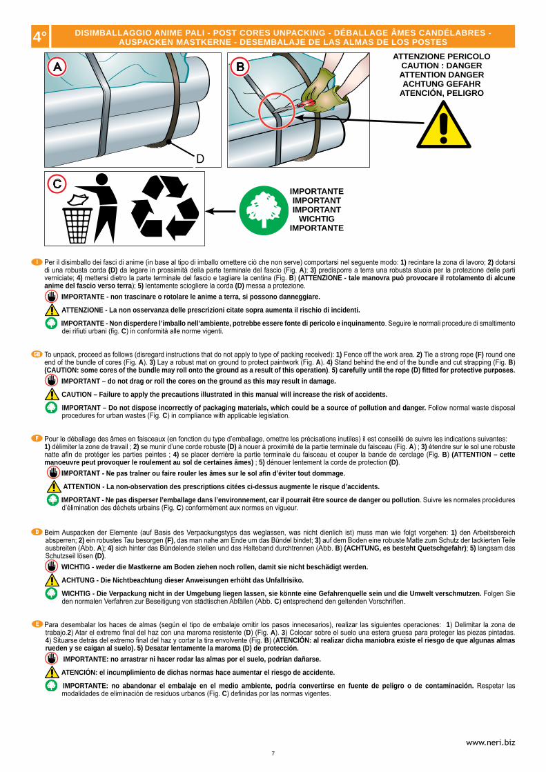
Per il disimballo dei fasci di anime (in base al tipo di imballo omettere ciò che non serve) comportarsi nel seguente modo: 1) recintare la zona di lavoro; 2) dotarsi di una robusta corda (D) da legare in prossimità della parte terminale del fascio (Fig. A); 3) predisporre a terra una robusta stuoia per la protezione delle parti verniciate; 4) mettersi dietro la parte terminale del fascio e tagliare la centina (Fig. B) (ATTENZIONE - tale manovra può provocare il rotolamento di alcune anime del fascio verso terra); 5) lentamente sciogliere la corda (D) messa a protezione.
IMPORTANTE - non trascinare o rotolare le anime a terra, si possono danneggiare.
ATTENZIONE - La non osservanza delle prescrizioni citate sopra aumenta il rischio di incidenti.
IMPORTANTE - Non disperdere l’imballo nell’ambiente, potrebbe essere fonte di pericolo e inquinamento. Seguire le normali procedure di smaltimento dei rifiuti urbani (fig. C) in conformità alle norme vigenti.
To unpack, proceed as follows (disregard instructions that do not apply to type of packing received): 1) Fence off the work area. 2) Tie a strong rope (F) round one end of the bundle of cores (Fig. A). 3) Lay a robust mat on ground to protect paintwork (Fig. A). 4) Stand behind the end of the bundle and cut strapping (Fig. B) (CAUTION: some cores of the bundle may roll onto the ground as a result of this operation). 5) carefully until the rope (D) fitted for protective purposes.
IMPORTANT – do not drag or roll the cores on the ground as this may result in damage.
CAUTION – Failure to apply the precautions illustrated in this manual will increase the risk of accidents.
IMPORTANT – Do not dispose incorrectly of packaging materials, which could be a source of pollution and danger. Follow normal waste disposal procedures for urban wastes (Fig. C) in compliance with applicable legislation.
Pour le déballage des âmes en faisceaux (en fonction du type d’emballage, omettre les précisations inutiles) il est conseillé de suivre les indications suivantes:1) délimiter la zone de travail ; 2) se munir d’une corde robuste (D) à nouer à proximité de la partie terminale du faisceau (Fig. A) ; 3) étendre sur le sol une robuste natte afin de protéger les parties peintes ; 4) se placer derrière la partie terminale du faisceau et couper la bande de cerclage (Fig. B) (ATTENTION – cette manoeuvre peut provoquer le roulement au sol de certaines âmes) ; 5) dénouer lentement la corde de protection (D).
IMPORTANT - Ne pas traîner ou faire rouler les âmes sur le sol afin d’éviter tout dommage.
ATTENTION - La non-observation des prescriptions citées ci-dessus augmente le risque d’accidents.
IMPORTANT - Ne pas disperser l’emballage dans l’environnement, car il pourrait être source de danger ou pollution. Suivre les normales procédures d’élimination des déchets urbains (Fig. C) conformément aux normes en vigueur.
Beim Auspacken der Elemente (auf Basis des Verpackungstyps das weglassen, was nicht dienlich ist) muss man wie folgt vorgehen: 1) den Arbeitsbereich absperren; 2) ein robustes Tau besorgen (F), das man nahe am Ende um das Bündel bindet; 3) auf dem Boden eine robuste Matte zum Schutz der lackierten Teile ausbreiten (Abb. A); 4) sich hinter das Bündelende stellen und das Halteband durchtrennen (Abb. B) (ACHTUNG, es besteht Quetschgefahr); 5) langsam das Schutzseil lösen (D).
WICHTIG - weder die Mastkerne am Boden ziehen noch rollen, damit sie nicht beschädigt werden.
ACHTUNG - Die Nichtbeachtung dieser Anweisungen erhöht das Unfallrisiko.
WICHTIG - Die Verpackung nicht in der Umgebung liegen lassen, sie könnte eine Gefahrenquelle sein und die Umwelt verschmutzen. Folgen Sie den normalen Verfahren zur Beseitigung von städtischen Abfällen (Abb. C) entsprechend den geltenden Vorschriften.
Para desembalar los haces de almas (según el tipo de embalaje omitir los pasos innecesarios), realizar las siguientes operaciones: 1) Delimitar la zona de trabajo.2) Atar el extremo final del haz con una maroma resistente (D) (Fig. A). 3) Colocar sobre el suelo una estera gruesa para proteger las piezas pintadas. 4) Situarse detrás del extremo final del haz y cortar la tira envolvente (Fig. B) (ATENCIÓN: al realizar dicha maniobra existe el riesgo de que algunas almas rueden y se caigan al suelo). 5) Desatar lentamente la maroma (D) de protección.
IMPORTANTE: no arrastrar ni hacer rodar las almas por el suelo, podrían dañarse.
ATENCIÓN: el incumplimiento de dichas normas hace aumentar el riesgo de accidente.
IMPORTANTE: no abandonar el embalaje en el medio ambiente, podría convertirse en fuente de peligro o de contaminación. Respetar las modalidades de eliminación de residuos urbanos (Fig. C) definidas por las normas vigentes.
ATTENZIONE PERICOLOCAUTION : DANGERATTENTION DANGERACHTUNG GEFAHR
ATENCIÓN, PELIGRO
IMPORTANTEIMPORTANTIMPORTANT
WICHTIGIMPORTANTE
4° DISIMBALLAGGIO ANIME PALI - POST CORES UNPACKING - DÉBALLAGE ÂMES CANDÉLABRES -AUSPACKEN MASTKERNE - DESEMBALAJE DE LAS ALMAS DE LOS POSTES
8
I
GB
F
D
E
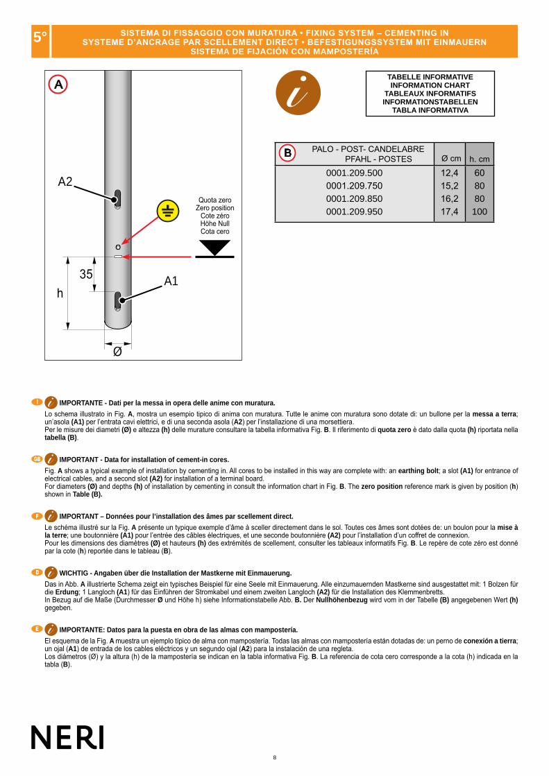
IMPORTANTE - Dati per la messa in opera delle anime con muratura.
Lo schema illustrato in Fig. A, mostra un esempio tipico di anima con muratura. Tutte le anime con muratura sono dotate di: un bullone per la messa a terra; un’asola (A1) per l’entrata cavi elettrici, e di una seconda asola (A2) per l’installazione di una morsettiera.Per le misure dei diametri (Ø) e altezza (h) delle murature consultare la tabella informativa Fig. B. Il riferimento di quota zero è dato dalla quota (h) riportata nella tabella (B).
IMPORTANT - Data for installation of cement-in cores.
Fig. A shows a typical example of installation by cementing in. All cores to be installed in this way are complete with: an earthing bolt; a slot (A1) for entrance of electrical cables, and a second slot (A2) for installation of a terminal board. For diameters (Ø) and depths (h) of installation by cementing in consult the information chart in Fig. B. The zero position reference mark is given by position (h) shown in Table (B).
IMPORTANT – Données pour l’installation des âmes par scellement direct.
Le schéma illustré sur la Fig. A présente un typique exemple d’âme à sceller directement dans le sol. Toutes ces âmes sont dotées de: un boulon pour la mise à la terre; une boutonnière (A1) pour l’entrée des câbles électriques, et une seconde boutonnière (A2) pour l’installation d’un coffret de connexion.Pour les dimensions des diamètres (Ø) et hauteurs (h) des extrémités de scellement, consulter les tableaux informatifs Fig. B. Le repère de cote zéro est donné par la cote (h) reportée dans le tableau (B).
WICHTIG - Angaben über die Installation der Mastkerne mit Einmauerung.
Das in Abb. A illustrierte Schema zeigt ein typisches Beispiel für eine Seele mit Einmauerung. Alle einzumauernden Mastkerne sind ausgestattet mit: 1 Bolzen für die Erdung; 1 Langloch (A1) für das Einführen der Stromkabel und einem zweiten Langloch (A2) für die Installation des Klemmenbretts.In Bezug auf die Maße (Durchmesser Ø und Höhe h) siehe Informationstabelle Abb. B. Der Nullhöhenbezug wird vom in der Tabelle (B) angegebenen Wert (h) gegeben.
IMPORTANTE: Datos para la puesta en obra de las almas con mampostería.
El esquema de la Fig. A muestra un ejemplo típico de alma con mampostería. Todas las almas con mampostería están dotadas de: un perno de conexión a tierra; un ojal (A1) de entrada de los cables eléctricos y un segundo ojal (A2) para la instalación de una regleta.Los diámetros (Ø) y la altura (h) de la mampostería se indican en la tabla informativa Fig. B. La referencia de cota cero corresponde a la cota (h) indicada en la tabla (B).
TABELLE INFORMATIVEINFORMATION CHART
TABLEAUX INFORMATIFSINFORMATIONSTABELLEN
TABLA INFORMATIVA
PALO - POST- CANDELABRE PFAHL - POSTES Ø cm h. cm
0001.209.5000001.209.7500001.209.8500001.209.950
12,415,216,217,4
608080100
B
5° SISTEMA DI FISSAGGIO CON MURATURA • FIXING SYSTEM – CEMENTING INSYSTEME D’ANCRAGE PAR SCELLEMENT DIRECT • BEFESTIGUNGSSYSTEM MIT EINMAUERN
SISTEMA DE FIJACIÓN CON MAMPOSTERÍA
A
A2
35h
Ø
A1
Quota zeroZero position
Cote zéroHöhe NullCota cero

9
www.neri.biz
0001.209.5010001.209.7510001.209.8510001.209.951
F1F2F2F2
ø 24,6 ø 9
90°
ø 18
2,2
F1
F2
2,2
60°
ø 34,1
ø 9
ø 27,5
I
GB
F
D
E
IMPORTANTE - Dati per la messa in opera delle anime con flangia.Lo schema illustrato in Fig. C, mostra un esempio tipico di anima con flangia. Tutte le anime con flangia sono dotate di: un bullone per la messa a terra; un’asola (A1) per l’installazione di una morsettiera; quattro o sei asole Ø 2,2 cm per tirafondi; un foro centrale Ø 9 cm per il passaggio dei cavi elettrici.Il simbolo ( ) indica la posizione dell’asola (A1). Il riferimento di quota zero è la base di appoggio della flangia.
IMPORTANT - Data for installation of cores with flange.Fig. C shows a typical example of installation with a flange. All cores to be installed in this way are complete with: an earthing bolt; a slot (A1) for installation of a terminal board; four or six slots Ø 2,2 cm for anchor bolts; a central hole Ø 9 cm for entry of the electrical cables.The ( ) shows the position of the slot (A1). The zero position reference mark is the supporting base of the flange.
IMPORTANT - Données pour l’installation des âmes avec bride.
Le schéma illustré sur la Fig. C présente un typique exemple d’âme avec semelle de fixation. Toutes les âmes avec semelle sont dotées de:un boulon pour la mise à la terre; une fente (A1) pour l’installation d’un bornier ; quatre ou six fentes Ø 2,2 cm pour tire-fond ; un trou central Ø 9 cm pour le passage des câbles électriques.Le symbole ( ) indique la position de la fente (A1). Le repère de cote zéro est la base d’appui de la bride.
Angaben für die Montage der Mastrohre mit Flansch.
Die Skizze von Abb. C zeigt ein typisches Beispiel eines Mastrohrs mit Flansch. Alle Mastrohre mit Flansch verfügen über Folgendes: eine Mutterschraube für die Erdung; ein Langloch (A1) für die Installation einer Klemmenleiste; vier oder sechs Langlöcher Ø 2,2 cm für Ankerbolzen; ein mittleres Loch Ø 9 cm für die Durchführung der Stromkabel.Das Symbol ( ) gibt die Position des Langlochs (A1) an. Der Bezugspunkt für die Höhe Null ist die Auflagefläche des Flansches.
IMPORTANTE: Datos para la puesta en obra de las almas con brida.
El esquema de la Fig. C muestra un ejemplo típico de alma con brida. Todas las almas con brida están dotadas de: un perno para la conexión a tierra, un ojal (A1) para la instalación de la regleta, cuatro o seis ojales Ø 2,2 cm para tirafondos y un orificio central Ø 9 cm para la entrada de los cables eléctricos.El símbolo ( ) indica la posición del ojal (A1). La referencia de cota cero se corresponde con la base de apoyo de la brida.
PALO - FLANGIAPOST - FLANGE
CANDELABRE-SEMELLEPFAHL - FLANSCHPOSTES - BRIDA
PALO - POST- CANDELABRE PFAHL - POSTES Ø cm h. cm
0001.209.5000001.209.7500001.209.8500001.209.950
12,415,216,217,4
608080
100
6° SISTEMA DI FISSAGGIO CON FLANGIA • FIXING SYSTEM – FLANGE • SYSTEME D’ANCRAGE AVEC SEMELLE DE FIXATION • BEFESTIGUNGSSYSTEM – FLANSCH - SISTEMA DE FIJACIÓN CON BRIDA
C
A1
Ø
Quota zeroZero position
Cote zéroHöhe NullCota cero
10
A B C D E
7°
I
GB
F
D
E
ATTENZIONE PERICOLOCAUTION : DANGERATTENTION DANGERACHTUNG GEFAHR
ATENCIÓN, PELIGRO
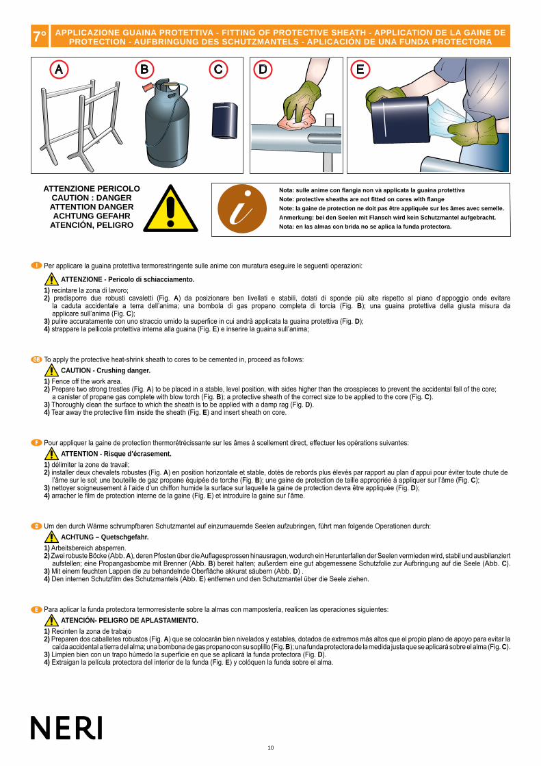
Nota: sulle anime con flangia non và applicata la guaina protettivaNote: protective sheaths are not fitted on cores with flangeNote: la gaine de protection ne doit pas être appliquée sur les âmes avec semelle.
Anmerkung: bei den Seelen mit Flansch wird kein Schutzmantel aufgebracht.
Nota: en las almas con brida no se aplica la funda protectora.
Per applicare la guaina protettiva termorestringente sulle anime con muratura eseguire le seguenti operazioni:
ATTENZIONE - Pericolo di schiacciamento.
1) recintare la zona di lavoro;2) predisporre due robusti cavaletti (Fig. A) da posizionare ben livellati e stabili, dotati di sponde più alte rispetto al piano d’appoggio onde evitare
la caduta accidentale a terra dell’anima; una bombola di gas propano completa di torcia (Fig. B); una guaina protettiva della giusta misura daapplicare sull’anima (Fig. C);
3) pulire accuratamente con uno straccio umido la superfice in cui andrà applicata la guaina protettiva (Fig. D);4) strappare la pellicola protettiva interna alla guaina (Fig. E) e inserire la guaina sull’anima;
To apply the protective heat-shrink sheath to cores to be cemented in, proceed as follows: CAUTION - Crushing danger.
1) Fence off the work area.2) Prepare two strong trestles (Fig. A) to be placed in a stable, level position, with sides higher than the crosspieces to prevent the accidental fall of the core;
a canister of propane gas complete with blow torch (Fig. B); a protective sheath of the correct size to be applied to the core (Fig. C).3) Thoroughly clean the surface to which the sheath is to be applied with a damp rag (Fig. D).4) Tear away the protective film inside the sheath (Fig. E) and insert sheath on core.
Pour appliquer la gaine de protection thermorétrécissante sur les âmes à scellement direct, effectuer les opérations suivantes: ATTENTION - Risque d’écrasement.
1) délimiter la zone de travail;2) installer deux chevalets robustes (Fig. A) en position horizontale et stable, dotés de rebords plus élevés par rapport au plan d’appui pour éviter toute chute de
l’âme sur le sol; une bouteille de gaz propane équipée de torche (Fig. B); une gaine de protection de taille appropriée à appliquer sur l’âme (Fig. C);3) nettoyer soigneusement à l’aide d’un chiffon humide la surface sur laquelle la gaine de protection devra être appliquée (Fig. D);4) arracher le film de protection interne de la gaine (Fig. E) et introduire la gaine sur l’âme.
Um den durch Wärme schrumpfbaren Schutzmantel auf einzumauernde Seelen aufzubringen, führt man folgende Operationen durch: ACHTUNG – Quetschgefahr.
1) Arbeitsbereich absperren.2) Zwei robuste Böcke (Abb. A), deren Pfosten über die Auflagesprossen hinausragen, wodurch ein Herunterfallen der Seelen vermieden wird, stabil und ausbilanziert
aufstellen; eine Propangasbombe mit Brenner (Abb. B) bereit halten; außerdem eine gut abgemessene Schutzfolie zur Aufbringung auf die Seele (Abb. C).3) Mit einem feuchten Lappen die zu behandelnde Oberfläche akkurat säubern (Abb. D) .4) Den internen Schutzfilm des Schutzmantels (Abb. E) entfernen und den Schutzmantel über die Seele ziehen.
Para aplicar la funda protectora termorresistente sobre la almas con mampostería, realicen las operaciones siguientes: ATENCIÓN- PELIGRO DE APLASTAMIENTO.
1) Recinten la zona de trabajo2) Preparen dos caballetes robustos (Fig. A) que se colocarán bien nivelados y estables, dotados de extremos más altos que el propio plano de apoyo para evitar la
caída accidental a tierra del alma; una bombona de gas propano con su soplillo (Fig. B); una funda protectora de la medida justa que se aplicará sobre el alma (Fig. C).3) Limpien bien con un trapo húmedo la superficie en que se aplicará la funda protectora (Fig. D).4) Extraigan la película protectora del interior de la funda (Fig. E) y colóquen la funda sobre el alma.
APPLICAZIONE GUAINA PROTETTIVA - FITTING OF PROTECTIVE SHEATH - APPLICATION DE LA GAINE DEPROTECTION - AUFBRINGUNG DES SCHUTZMANTELS - APLICACIÓN DE UNA FUNDA PROTECTORA
11
www.neri.biz
F
I
G
L
H
M N
7°
I
GB
F
D
E
ATTENZIONE PERICOLOCAUTION : DANGERATTENTION DANGERACHTUNG GEFAHR
ATENCIÓN, PELIGRO
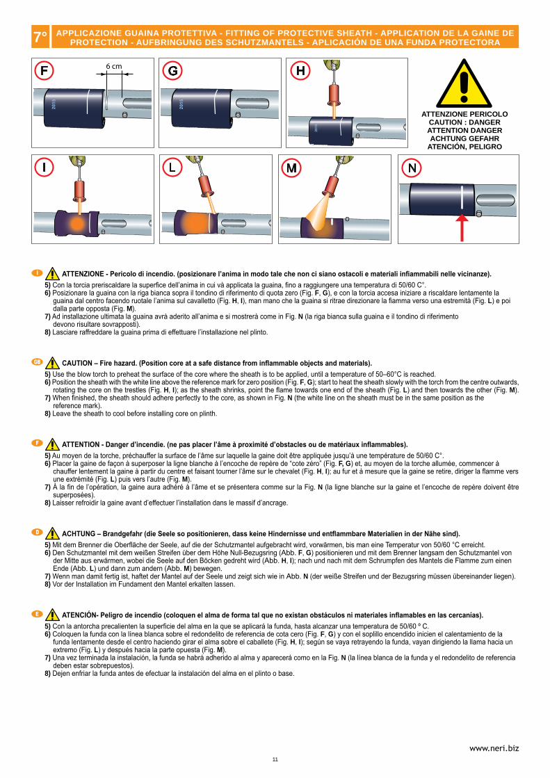
ATTENZIONE - Pericolo di incendio. (posizionare l’anima in modo tale che non ci siano ostacoli e materiali infiammabili nelle vicinanze).5) Con la torcia preriscaldare la superfice dell’anima in cui và applicata la guaina, fino a raggiungere una temperatura di 50/60 C°.6) Posizionare la guaina con la riga bianca sopra il tondino di riferimento di quota zero (Fig. F, G), e con la torcia accesa iniziare a riscaldare lentamente la
guaina dal centro facendo ruotale l’anima sul cavalletto (Fig. H, I), man mano che la guaina si ritrae direzionare la fiamma verso una estremità (Fig. L) e poi dalla parte opposta (Fig. M).
7) Ad installazione ultimata la guaina avrà aderito all’anima e si mostrerà come in Fig. N (la riga bianca sulla guaina e il tondino di riferimentodevono risultare sovrapposti).
8) Lasciare raffreddare la guaina prima di effettuare l’installazione nel plinto.
CAUTION – Fire hazard. (Position core at a safe distance from inflammable objects and materials).5) Use the blow torch to preheat the surface of the core where the sheath is to be applied, until a temperature of 50–60°C is reached.6) Position the sheath with the white line above the reference mark for zero position (Fig. F, G); start to heat the sheath slowly with the torch from the centre outwards,
rotating the core on the trestles (Fig. H, I); as the sheath shrinks, point the flame towards one end of the sheath (Fig. L) and then towards the other (Fig. M).7) When finished, the sheath should adhere perfectly to the core, as shown in Fig. N (the white line on the sheath must be in the same position as the
reference mark).8) Leave the sheath to cool before installing core on plinth.
ATTENTION - Danger d’incendie. (ne pas placer l’âme à proximité d’obstacles ou de matériaux inflammables).5) Au moyen de la torche, préchauffer la surface de l’âme sur laquelle la gaine doit être appliquée jusqu’à une température de 50/60 C°.6) Placer la gaine de façon à superposer la ligne blanche à l’encoche de repère de “cote zéro” (Fig. F, G) et, au moyen de la torche allumée, commencer à
chauffer lentement la gaine à partir du centre et faisant tourner l’âme sur le chevalet (Fig. H, I); au fur et à mesure que la gaine se retire, diriger la flamme vers une extrémité (Fig. L) puis vers l’autre (Fig. M).
7) À la fin de l’opération, la gaine aura adhéré à l’âme et se présentera comme sur la Fig. N (la ligne blanche sur la gaine et l’encoche de repère doivent être superposées).
8) Laisser refroidir la gaine avant d’effectuer l’installation dans le massif d’ancrage.
ACHTUNG – Brandgefahr (die Seele so positionieren, dass keine Hindernisse und entflammbare Materialien in der Nähe sind).5) Mit dem Brenner die Oberfläche der Seele, auf die der Schutzmantel aufgebracht wird, vorwärmen, bis man eine Temperatur von 50/60 °C erreicht.6) Den Schutzmantel mit dem weißen Streifen über dem Höhe Null-Bezugsring (Abb. F, G) positionieren und mit dem Brenner langsam den Schutzmantel von
der Mitte aus erwärmen, wobei die Seele auf den Böcken gedreht wird (Abb. H, I); nach und nach mit dem Schrumpfen des Mantels die Flamme zum einen Ende (Abb. L) und dann zum andern (Abb. M) bewegen.
7) Wenn man damit fertig ist, haftet der Mantel auf der Seele und zeigt sich wie in Abb. N (der weiße Streifen und der Bezugsring müssen übereinander liegen).8) Vor der Installation im Fundament den Mantel erkalten lassen.
ATENCIÓN- Peligro de incendio (coloquen el alma de forma tal que no existan obstáculos ni materiales inflamables en las cercanías).5) Con la antorcha precalienten la superficie del alma en la que se aplicará la funda, hasta alcanzar una temperatura de 50/60 º C.6) Coloquen la funda con la línea blanca sobre el redondelito de referencia de cota cero (Fig. F, G) y con el soplillo encendido inicien el calentamiento de la
funda lentamente desde el centro haciendo girar el alma sobre el caballete (Fig. H, I); según se vaya retrayendo la funda, vayan dirigiendo la llama hacia un extremo (Fig. L) y después hacia la parte opuesta (Fig. M).
7) Una vez terminada la instalación, la funda se habrá adherido al alma y aparecerá como en la Fig. N (la línea blanca de la funda y el redondelito de referencia deben estar sobrepuestos).
8) Dejen enfriar la funda antes de efectuar la instalación del alma en el plinto o base.
APPLICAZIONE GUAINA PROTETTIVA - FITTING OF PROTECTIVE SHEATH - APPLICATION DE LA GAINE DEPROTECTION - AUFBRINGUNG DES SCHUTZMANTELS - APLICACIÓN DE UNA FUNDA PROTECTORA
12
HB
P
L
I
GB
F
D
E
H
5 cm
P
L
A B
G
P
P
G
T
I
GB
F
D
E
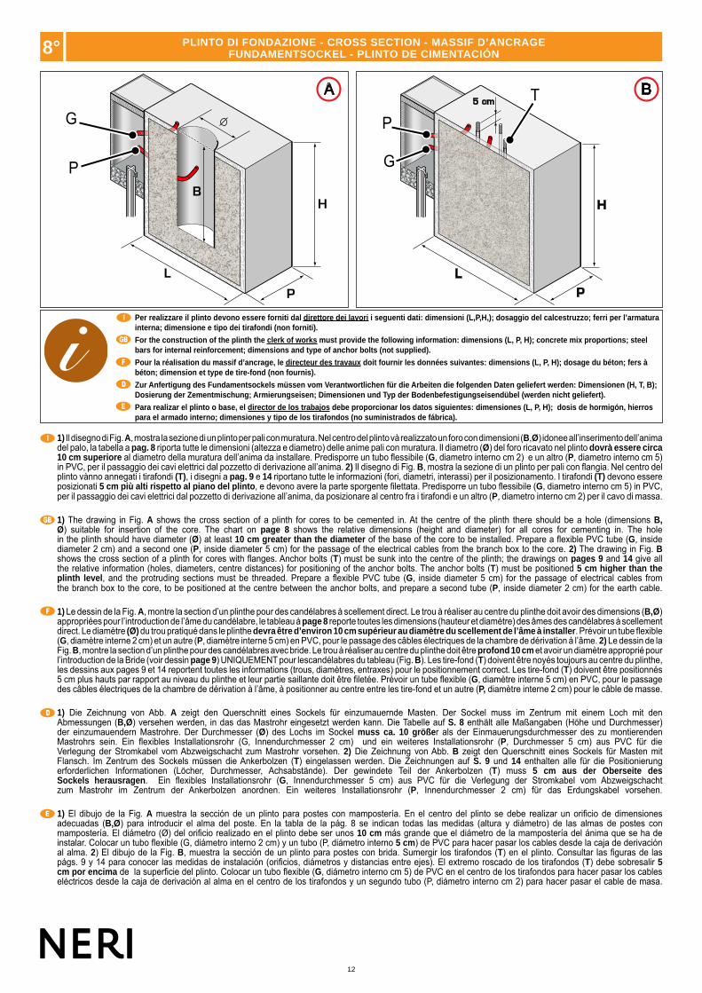
Per realizzare il plinto devono essere forniti dal direttore dei lavori i seguenti dati: dimensioni (L,P,H,); dosaggio del calcestruzzo; ferri per l’armatura interna; dimensione e tipo dei tirafondi (non forniti).
For the construction of the plinth the clerk of works must provide the following information: dimensions (L, P, H); concrete mix proportions; steel bars for internal reinforcement; dimensions and type of anchor bolts (not supplied).
Pour la réalisation du massif d’ancrage, le directeur des travaux doit fournir les données suivantes: dimensions (L, P, H); dosage du béton; fers à béton; dimension et type de tire-fond (non fournis).
Zur Anfertigung des Fundamentsockels müssen vom Verantwortlichen für die Arbeiten die folgenden Daten geliefert werden: Dimensionen (H, T, B); Dosierung der Zementmischung; Armierungseisen; Dimensionen und Typ der Bodenbefestigungseisendübel (werden nicht geliefert).
Para realizar el plinto o base, el director de los trabajos debe proporcionar los datos siguientes: dimensiones (L, P, H); dosis de hormigón, hierros para el armado interno; dimensiones y tipo de los tirafondos (no suministrados de fábrica).
1) Il disegno di Fig. A, mostra la sezione di un plinto per pali con muratura. Nel centro del plinto và realizzato un foro con dimensioni (B,Ø) idonee all’inserimento dell’anima del palo, la tabella a pag. 8 riporta tutte le dimensioni (altezza e diametro) delle anime pali con muratura. Il diametro (Ø) del foro ricavato nel plinto dovrà essere circa 10 cm superiore al diametro della muratura dell’anima da installare. Predisporre un tubo flessibile (G, diametro interno cm 2) e un altro (P, diametro interno cm 5) in PVC, per il passaggio dei cavi elettrici dal pozzetto di derivazione all’anima. 2) Il disegno di Fig. B, mostra la sezione di un plinto per pali con flangia. Nel centro del plinto vànno annegati i tirafondi (T), i disegni a pag. 9 e 14 riportano tutte le informazioni (fori, diametri, interassi) per il posizionamento. I tirafondi (T) devono essere posizionati 5 cm più alti rispetto al piano del plinto, e devono avere la parte sporgente filettata. Predisporre un tubo flessibile (G, diametro interno cm 5) in PVC, per il passaggio dei cavi elettrici dal pozzetto di derivazione all’anima, da posizionare al centro fra i tirafondi e un altro (P, diametro interno cm 2) per il cavo di massa.
1) The drawing in Fig. A shows the cross section of a plinth for cores to be cemented in. At the centre of the plinth there should be a hole (dimensions B,Ø) suitable for insertion of the core. The chart on page 8 shows the relative dimensions (height and diameter) for all cores for cementing in. The holein the plinth should have diameter (Ø) at least 10 cm greater than the diameter of the base of the core to be installed. Prepare a flexible PVC tube (G, inside diameter 2 cm) and a second one (P, inside diameter 5 cm) for the passage of the electrical cables from the branch box to the core. 2) The drawing in Fig. B shows the cross section of a plinth for cores with flanges. Anchor bolts (T) must be sunk into the centre of the plinth; the drawings on pages 9 and 14 give all the relative information (holes, diameters, centre distances) for positioning of the anchor bolts. The anchor bolts (T) must be positioned 5 cm higher than the plinth level, and the protruding sections must be threaded. Prepare a flexible PVC tube (G, inside diameter 5 cm) for the passage of electrical cables from the branch box to the core, to be positioned at the centre between the anchor bolts, and prepare a second tube (P, inside diameter 2 cm) for the earth cable.
1) Le dessin de la Fig. A, montre la section d’un plinthe pour des candélabres à scellement direct. Le trou à réaliser au centre du plinthe doit avoir des dimensions (B,Ø) appropriées pour l’introduction de l’âme du candélabre, le tableau à page 8 reporte toutes les dimensions (hauteur et diamètre) des âmes des candélabres à scellement direct. Le diamètre (Ø) du trou pratiqué dans le plinthe devra être d’environ 10 cm supérieur au diamètre du scellement de l’âme à installer. Prévoir un tube flexible (G, diamètre interne 2 cm) et un autre (P, diamètre interne 5 cm) en PVC, pour le passage des câbles électriques de la chambre de dérivation à l’âme. 2) Le dessin de la Fig. B, montre la section d’un plinthe pour des candélabres avec bride. Le trou à réaliser au centre du plinthe doit être profond 10 cm et avoir un diamètre approprié pour l’introduction de la Bride (voir dessin page 9) UNIQUEMENT pour lescandélabres du tableau (Fig. B). Les tire-fond (T) doivent être noyés toujours au centre du plinthe, les dessins aux pages 9 et 14 reportent toutes les informations (trous, diamètres, entraxes) pour le positionnement correct. Les tire-fond (T) doivent être positionnés 5 cm plus hauts par rapport au niveau du plinthe et leur partie saillante doit être filetée. Prévoir un tube flexible (G, diamètre interne 5 cm) en PVC, pour le passage des câbles électriques de la chambre de dérivation à l’âme, à positionner au centre entre les tire-fond et un autre (P, diamètre interne 2 cm) pour le câble de masse.
1) Die Zeichnung von Abb. A zeigt den Querschnitt eines Sockels für einzumauernde Masten. Der Sockel muss im Zentrum mit einem Loch mit den Abmessungen (B,Ø) versehen werden, in das das Mastrohr eingesetzt werden kann. Die Tabelle auf S. 8 enthält alle Maßangaben (Höhe und Durchmesser) der einzumauendern Mastrohre. Der Durchmesser (Ø) des Lochs im Sockel muss ca. 10 größer als der Einmauerungsdurchmesser des zu montierenden Mastrohrs sein. Ein flexibles Installationsrohr (G, Innendurchmesser 2 cm) und ein weiteres Installationsrohr (P, Durchmesser 5 cm) aus PVC für die Verlegung der Stromkabel vom Abzweigschacht zum Mastrohr vorsehen. 2) Die Zeichnung von Abb. B zeigt den Querschnitt eines Sockels für Masten mit Flansch. Im Zentrum des Sockels müssen die Ankerbolzen (T) eingelassen werden. Die Zeichnungen auf S. 9 und 14 enthalten alle für die Positionierung erforderlichen Informationen (Löcher, Durchmesser, Achsabstände). Der gewindete Teil der Ankerbolzen (T) muss 5 cm aus der Oberseite des Sockels herausragen. Ein flexibles Installationsrohr (G, Innendurchmesser 5 cm) aus PVC für die Verlegung der Stromkabel vom Abzweigschacht zum Mastrohr im Zentrum der Ankerbolzen anordnen. Ein weiteres Installationsrohr (P, Innendurchmesser 2 cm) für das Erdungskabel vorsehen.
1) El dibujo de la Fig. A muestra la sección de un plinto para postes con mampostería. En el centro del plinto se debe realizar un orificio de dimensiones adecuadas (B,Ø) para introducir el alma del poste. En la tabla de la pág. 8 se indican todas las medidas (altura y diámetro) de las almas de postes con mampostería. El diámetro (Ø) del orificio realizado en el plinto debe ser unos 10 cm más grande que el diámetro de la mampostería del ánima que se ha de instalar. Colocar un tubo flexible (G, diámetro interno 2 cm) y un tubo (P, diámetro interno 5 cm) de PVC para hacer pasar los cables desde la caja de derivación al alma. 2) El dibujo de la Fig. B, muestra la sección de un plinto para postes con brida. Sumergir los tirafondos (T) en el plinto. Consultar las figuras de las págs. 9 y 14 para conocer las medidas de instalación (orificios, diámetros y distancias entre ejes). El extremo roscado de los tirafondos (T) debe sobresalir 5 cm por encima de la superficie del plinto. Colocar un tubo flexible (G, diámetro interno cm 5) de PVC en el centro de los tirafondos para hacer pasar los cables eléctricos desde la caja de derivación al alma en el centro de los tirafondos y un segundo tubo (P, diámetro interno cm 2) para hacer pasar el cable de masa.
8° PLINTO DI FONDAZIONE - CROSS SECTION - MASSIF D’ANCRAGEFUNDAMENTSOCKEL - PLINTO DE CIMENTACIÓN

13
www.neri.biz
BA
R
250 Kg
I
GB
F
D
E
ATTENZION - CAUTIONATTENTION - ACHTUNG
ATENCIÓN
9° IMBRACATURA PALO - POST SLINGING - ÉLINGAGE CANDÉLABRE - ANSCHLAG LICHTMAST - ESLINGADO DEL POSTE
ATTENZIONE - Recintare la zona di lavoro. Se si utilizza un braccio meccanico per il sollevamento dell’anima (vedi tabella pesi e altezze anime a pag. 6) attuare tutte le prescrizioni sull’uso in sicurezza di tale braccio. ATTENZIONE - Pericolo di oscillazione.
Per imbragare l’anima eseguire le istruzioni sotto elencate:1) Munirsi di due fasce in tessuto (R) senza ganci con portata non inferiore a 250 Kg e di lunghezza idonea (vedi altezza anima a pag. 6) (Fig. A).2) Inserire una fascia nella zona di aggancio del corpo illuminnate e un’altra nella zona di incrocio del palo con il braccio, come mostrato nella Fig. B.3) Agganciare le fasce al gancio del braccio meccanico e sollevare lentamente l’anima. Verificare che l’elemento sia in perfetto equilibrio.
CAUTION - Fence off the work area. If a crane is used to lift the core (see chart with weights on page 6) take all precautions for the safe use of this equipment. CAUTION: Danger of swinging objects.
To harness up the core to be lifted follow these instructions:1) Procure two fabric hoisting belts (R) without hooks, with a lifting capacity of at least 250 kg and of a suitable length (see core heights on page 6) (Fig. A).2) Insert one belt in the light fixture coupling area and the other in the area where the post and arm meet, as illustrated in Fig. B. 3) Attach the belts to the crane arm and slowly lift the core. Check that the element is perfectly balanced.
ATTENTION - Délimiter la zone de travail. Dans le cas d’utilisation d’un bras mécanique pour le levage de l’âme (voir tableau poids et hauteursdes âmes à pag. 6) respecter toutes les prescriptions de sécurité concernant l’utilisation de ces appareils. ATTENTION, risque d’oscillations.
Pour élinguer l’âme, suivre les instructions suivantes :1) S’équiper de deux bandes en tissu (R) sans crochets d’une portée non inférieure à 250 kg et d’une longueur appropriée (voir hauteur âme à la page 6) (Fig. A).2) Introduire une bande dans la zone d’accrochage de l’armature d’éclairage et une autre danz la zone de croisement du candélabre avec le bras, comme indiqué
dans la Fig. B.3) Accrocher les bandes au crochet du bras mécanique et soulever lentement l’âme. Vérifier que l’élément soit en parfait équilibre.
ACHTUNG - Den Den Arbeitsbereich absperren. Wird zum Anheben des Mastrohrs ein Mobilkran verwendet (siehe die Tabelle mit den Angaben zum Gewicht und zur Höhe der Mastrohre auf S. 6) alle Vorschriften in Bezug auf den sicheren Gebrauch dieses Mobilkrans beachten. ACHTUNG: Die Last kann ins Schwingen geraten.
Zum Anschlagen des Mastrohrs die nachstehenden Anweisungen befolgen:1) Zwei Gewebegurte (R) ohne Haken verwenden, deren Tragfähigkeit mindestens 250 kg beträgt und die eine geeignete Länge haben (siehe die Höhe des
Mastrohrs auf S. 6) (Abb. A).2) Einen Gurt im Anschlagbereich des Leuchtkörpers und den anderen dort anschlagen, wo sich der Mast und der Arm kreuzen (siehe Abb. B). 3) Die Schlinge am Haken des mechanischen Arms einhängen und den Mastkern langsam anheben.
ATENCIÓN - Delimitar la zona de trabajo. Si se utiliza un brazo mecánico para elevar el alma (véase la tabla de pesos y alturas en la pág. 6), respetar las normas de uso para utilizar el brazo de modo seguro. ATENCIÓN: peligro de oscilación.
Para eslingar el alma, respetar las siguientes instrucciones:1) Utilizar dos eslingas de tela (R) sin ganchos con capacidad para soportar cargas de más de 250 kg y que posean una longitud adecuada (véase la altura del
alma en la pág. 6, Fig. A).2) Introducir una de las eslingas en la zona de enganche del cuerpo de iluminación y la otra en la zona de unión del palo y el brazo, como muestra la figura B.3) Enganchar las eslingas al gancho del brazo mecánico y levantar lentamente el alma. Comprobar que el elemento esté equilibrado correctamente.

14
A 0001.209.5000001.209.501
0001.209.7500001.209.7510001.209.8500001.209.8510001.209.9500001.209.951
RF
G
PALO - POST- CANDELABREPFAHL - POSTES
G (cm)
A001.209.750A001.209.850A001.209.950A001.209.751A001.209.851A001.209.951
1007050
1007050
I
GB
F
D
E
I
GB
F
D
E
10° INSTALLAZIONE ANIME PALI - POST CORES INSTALLATION - INSTALLATION ÂMES CANDÉLABRES - INSTALLATION MASTKERNE - INSTALACIÓN DE LAS ALMAS EN LOS POSTES
Lo schema A mette in evidenza due tipi di posizionamento delle anime con flangia e muratura in base alla tipologia di palo montato. Posizione 1: l’asola è posizionata parallela alla carreggiata stradale, il braccio sarà disposto come in figura 1.Posizione 2: l’asola è posizionata dalla parte della carreggiata stradale, il braccio sarà disposto come in figura 2.
Diagram A shows two types of core positing using masonry or flange, depending on the type of post installed.Position 1: the slot is located parallel to the roadway and the lighting arm is positioned as shown in figure 1.Position 2: the slot is located on the roadway side and the lighting arm is positioned as shown in figure 2.
Le schéma A met en évidence deux types de positionnement des âmes à scellement direct ou à bride, suivant le type de candélabre monté.Position 1 : la fente est positionnée parallèlement à la chaussée, le bras sera disposé comme indiqué sur la figure 1.Position 2 : la fente est positionnée sur le côté de la chaussée, le bras sera disposé comme indiqué sur la figure 2.
Die Skizze A zeigt je nach montiertem Mast zwei Arten der Anordnung der Mastrohre mit Flansch bzw. der einzumauernden Mastrohre.Position 1: Das Langloch ist parallel zur Fahrbahn ausgerichtet; der Arm ist wie in Abbildung 1 dargestellt angeordnet.Position 2: Das Langloch befindet sich auf der Seite der Fahrbahn; der Arm ist wie in Abbildung 2 dargestellt angeordnet.
El esquema A muestra dos tipos de instalación de las almas con brida y mampostería en función del tipo de poste.Posición 1: el ojal debe estar colocado en paralelo con la calzada, el brazo debe estar colocado como muestra la figura 1.Posición 2: el ojal debe estar colocado hacia la calzada, el brazo debe estar colocado como muestra la figura 2.
Lo schema in Fig. F mette in evidenza il posizionamento dei pali rispetto alla careggiata stradale. In particolare il palo deve essere posizionato ad una distanza (G), riportata nella tabella sopra, dall’inizio della parte carrabile della carreggiata; in modo da permettere il transito di veicoli (R) con altezza fino a 6 m.
The diagram in Fig. F highlights the position of the posts in relation to the roadway. In particular to allow the transit of vehicles (R) with a height of up to 6 m the post must be positioned at the distance (G) from the beginning of the roadway section open to traffic as indicated in the table above.
Le schéma de la Fig. F met en évidence le positionnement des candélabres par rapport à la chaussée routière. En particulier le candélabre doit être positionné à une distance (G), reportée dans le tableau ci-dessus, du début de la partie de roulement de la chaussée, afin de permettre le passage de véhicules (R) ayant une hauteur jusqu’à 6 m.
Die Skizze in Abb. F zeigt die Positionierung der Masten zur Fahrbahn. Insbesondere muss der Mast in dem in der oberen Tabelle angegebenen Abstand (G) zum Anfang des befahrbaren Teils der Fahrbahn positioniert werden, um die Vorbeifahrt von Fahrzeugen (R) mit einer Höhe bis 6 m zu ermöglichen.
El esquema de la Fig. F muestra la posición de los postes respecto de la calzada. El poste debe estar situado a la distancia (G) del inicio de la parte transitable de la calzada (indicada en la tabla anterior), para consentir el tránsito de los vehículos (R) de más de 6 m de altura.
Inizio parte carrabile della carreggiata.Beginning of the roadway section open to traffic.Début de la partie de roulement de la chaussée.Anfang des befahrbaren Teils der Fahrbahn.Inicio de la parte transitable de la calzada.
ALTEZZA DI 6 m.
HEIGHT of 6 m
HAUTEUR DE 6 m.
HÖHE 6 m.
ALTURA 6 m

15
www.neri.biz
B C
I
GB
F
D
E
ATTENZIONE - Recintare la zona di lavoro, pericolo di oscillazioni. Se si utilizza un braccio meccanico per il sollevamento dell’animaeseguire le operazioni di imbracatura descritte al capitolo 9 (pag. 13).
Per l’installazione di anime con muratura eseguire le sottostanti operazioni:1) Verificare che il plinto sia ben consolidato. Molto lentamente e delicatamente in modo da non danneggiare l’anima, infilarla nel foro del plinto inserendo il tubo
flessibile, per il passaggio dei cavi elettrici, nell’asola dell’anima stessa.2) Verificare la corretta posizione delle asole rispetto alla carreggiata stradale (vedi pag.14). Livellare l’anima verificando che la tacca di riferimento quota zero
(segnalata sull’anima) corrisponda al piano di pavimentazione finale (Fig. B). L’anima deve essere posizionata perfettamente a piombo (Fig. B).3) A questo punto fissarla con una colata di cemento a presa rapida riempendo il foro del plinto rimasto libero (Fig. C). Liberare l’anima dall’imbracatura.
CAUTION - Fence off the work area. Danger of swinging objects. If a crane is used to lift the core, secure lifting cable as described in section 10 (page 13).
To install cores for cementing in proceed as follows:1) Check that the plinth has hardened sufficiently. Very slowly and carefully, in such a way as to avoid damage to the core, insert the core into the plinth, inserting
the flexible hose for entry of the electrical cables into the core slot.2) Check that the slots are in the correct position with respect to the roadway (see page 14). Level the core, checking that the zero position reference mark (on
the core) corresponds with the final paving level (Fig. B). The core must be positioned so that it is perfectly vertical (Fig. B).3) Now secure the core by filling the gap around the base with quick-setting cement (Fig. C). Free the core from the lifting cable.
ATTENTION - Délimiter la zone de travail, risque d’oscillations. Dans le cas d’utilisation d’un bras mécanique pour le levage de l’âme, effectuer les opérations d’élingage décrites au chapitre 10 (pag. 13).
Pour l’installation d’âmes à scellement direct, effectuer les opérations suivantes:1) Vérifier que le massif d’ancrage soit bien consolidé. Introduire très lentement et délicatement l’âme dans le trou du plinthe afin d’éviter tout endommagement,
en introduisant le tube flexible, pour le passage des câbles électriques, dans la fente de l’âme même.2) Vérifier la juste position des boutonnières par rapport à la chaussée (voir pag. 14). Niveler l’âme en vérifiant que le repère de cote zéro (indiqué sur l’âme)
corresponde au plan de pavement final (Fig. B). L’âme doit être installée dans une position parfaitement verticale (Fig. B).3) Fixer à présent l’âme à l’aide d’une coulée de ciment à prise rapide en remplissant l’espace resté libre dans le trou du plinthe (Fig. C). Libérer l’âme de l’élingue.
ACHTUNG - Den Arbeitsbereich absperren, Schwingungsgefahr. Wenn man einen mechanischen Arm zum Anheben der Seele benutzt, muss man die Anschirrarbeiten durchführen, wie sie im Kapitel 10 (Seite 13) beschrieben sind.
Zur Installation der einzumauernden Seelen führt man die folgenden Operationen durch:1) Überprüfen, dass der Sockel fest geworden ist. Um Beschädigungen zu vermeiden, den Mastkern sehr langsam und vorsichtig in die Bohrung des Sockels und
das flexible Rohr zum Verlegen der elektrischen Kabel im Langloch des Mastkerns selbst, einführen.2) Die korrekte Positionierung der Öffnungen im Verhältnis zur Fahrbahn überprüfen (siehe Seite 14). Den Mastkern nivellieren indem geprüft wird, dass die Bezugskerbe
Nullhöhe (auf dem Mastkern angegeben) mit der Endbodenfläche übereinstimmt (Abb. B). Der Mastkern muss perfekt senkrecht (Abb. B) ausgerichtet sein.3) Diesen dann, durch Auffüllen des Freiraums der Sockelbohrung, mit einem Schnellzementguss befestigen (Abb. C). Die Seele vom Geschirr lösen.
ATENCIÓN: delimitar la zona de trabajo, peligro de oscilaciones. Si se utiliza un brazo mecánico para elevar el alma, respetar las operaciones de eslingado que se describen en el capítulo 9 (pág. 13).
Para la instalación de almas con mampostería, realizar las operaciones siguientes:1) Comprobar que el plinto esté bien consolidado. Introducir el alma en el agujero del plinto de modo muy lento y con cuidado para no dañarla e introducir el tubo
flexible en el ojal del alma, para pasar los cables eléctricos.2) Controlar que los ojales estén colocados correctamente con respecto a la calzada (véase la pág.14). Nivelar el alma y comprobar que la marca de referencia de
la cota cero (grabada en el alma) se corresponda con el nivel del pavimento final (Fig. B). El alma se debe colocar en posición perfectamente vertical (Fig. B).3) Ahora, fijarla con una colada de cemento de secado rápido llenando el agujero del plinto que está libre (Fig. C). Liberar el ánima de las eslingas.
10° INSTALLAZIONE ANIME PALI - POST CORES INSTALLATION - INSTALLATION ÂMES CANDÉLABRES - INSTALLATION MASTKERNE - INSTALACIÓN DE LAS ALMAS EN LOS POSTES
16
5 cm
D E
I
GB
F
D
E
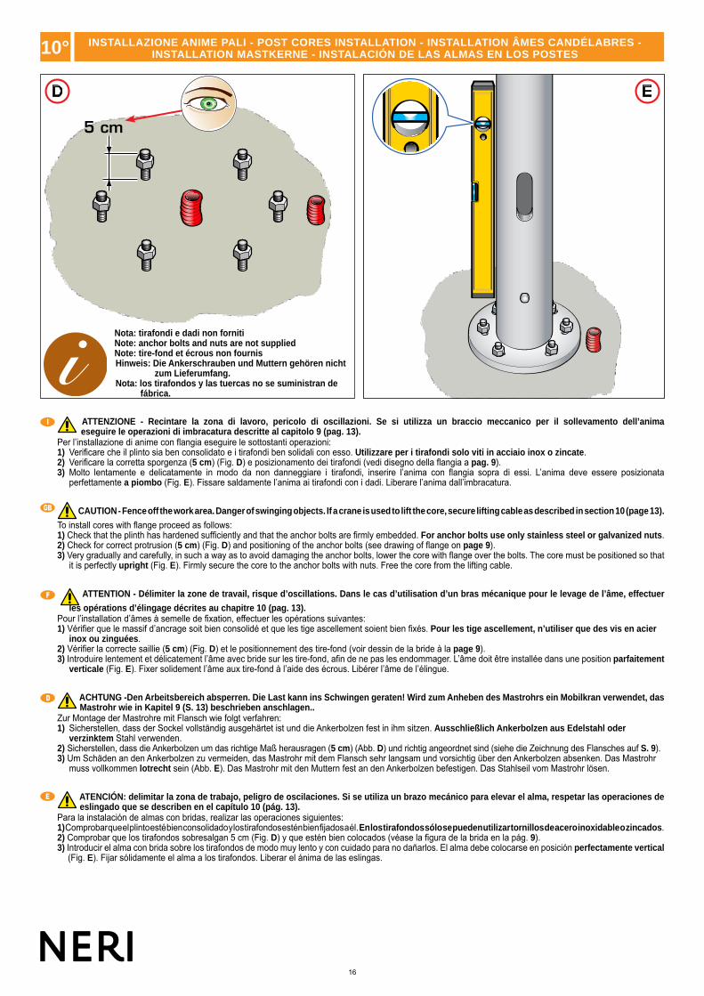
ATTENZIONE - Recintare la zona di lavoro, pericolo di oscillazioni. Se si utilizza un braccio meccanico per il sollevamento dell’animaeseguire le operazioni di imbracatura descritte al capitolo 9 (pag. 13).
Per l’installazione di anime con flangia eseguire le sottostanti operazioni:1) Verificare che il plinto sia ben consolidato e i tirafondi ben solidali con esso. Utilizzare per i tirafondi solo viti in acciaio inox o zincate.2) Verificare la corretta sporgenza (5 cm) (Fig. D) e posizionamento dei tirafondi (vedi disegno della flangia a pag. 9).3) Molto lentamente e delicatamente in modo da non danneggiare i tirafondi, inserire l’anima con flangia sopra di essi. L’anima deve essere posizionata
perfettamente a piombo (Fig. E). Fissare saldamente l’anima ai tirafondi con i dadi. Liberare l’anima dall’imbracatura.
CAUTION - Fence off the work area. Danger of swinging objects. If a crane is used to lift the core, secure lifting cable as described in section 10 (page 13).
To install cores with flange proceed as follows:1) Check that the plinth has hardened sufficiently and that the anchor bolts are firmly embedded. For anchor bolts use only stainless steel or galvanized nuts.2) Check for correct protrusion (5 cm) (Fig. D) and positioning of the anchor bolts (see drawing of flange on page 9).3) Very gradually and carefully, in such a way as to avoid damaging the anchor bolts, lower the core with flange over the bolts. The core must be positioned so that
it is perfectly upright (Fig. E). Firmly secure the core to the anchor bolts with nuts. Free the core from the lifting cable.
ATTENTION - Délimiter la zone de travail, risque d’oscillations. Dans le cas d’utilisation d’un bras mécanique pour le levage de l’âme, effectuer
les opérations d’élingage décrites au chapitre 10 (pag. 13).Pour l’installation d’âmes à semelle de fixation, effectuer les opérations suivantes:1) Vérifier que le massif d’ancrage soit bien consolidé et que les tige ascellement soient bien fixés. Pour les tige ascellement, n’utiliser que des vis en acier
inox ou zinguées.2) Vérifier la correcte saillie (5 cm) (Fig. D) et le positionnement des tire-fond (voir dessin de la bride à la page 9).3) Introduire lentement et délicatement l’âme avec bride sur les tire-fond, afin de ne pas les endommager. L’âme doit être installée dans une position parfaitement
verticale (Fig. E). Fixer solidement l’âme aux tire-fond à l’aide des écrous. Libérer l’âme de l’élingue.
ACHTUNG -Den Arbeitsbereich absperren. Die Last kann ins Schwingen geraten! Wird zum Anheben des Mastrohrs ein Mobilkran verwendet, das Mastrohr wie in Kapitel 9 (S. 13) beschrieben anschlagen..
Zur Montage der Mastrohre mit Flansch wie folgt verfahren:1) Sicherstellen, dass der Sockel vollständig ausgehärtet ist und die Ankerbolzen fest in ihm sitzen. Ausschließlich Ankerbolzen aus Edelstahl oder
verzinktem Stahl verwenden.2) Sicherstellen, dass die Ankerbolzen um das richtige Maß herausragen (5 cm) (Abb. D) und richtig angeordnet sind (siehe die Zeichnung des Flansches auf S. 9).3) Um Schäden an den Ankerbolzen zu vermeiden, das Mastrohr mit dem Flansch sehr langsam und vorsichtig über den Ankerbolzen absenken. Das Mastrohr
muss vollkommen lotrecht sein (Abb. E). Das Mastrohr mit den Muttern fest an den Ankerbolzen befestigen. Das Stahlseil vom Mastrohr lösen.
ATENCIÓN: delimitar la zona de trabajo, peligro de oscilaciones. Si se utiliza un brazo mecánico para elevar el alma, respetar las operaciones de eslingado que se describen en el capítulo 10 (pág. 13).
Para la instalación de almas con bridas, realizar las operaciones siguientes:1) Comprobar que el plinto esté bien consolidado y los tirafondos estén bien fijados a él. En los tirafondos sólo se pueden utilizar tornillos de acero inoxidable o zincados.2) Comprobar que los tirafondos sobresalgan 5 cm (Fig. D) y que estén bien colocados (véase la figura de la brida en la pág. 9).3) Introducir el alma con brida sobre los tirafondos de modo muy lento y con cuidado para no dañarlos. El alma debe colocarse en posición perfectamente vertical
(Fig. E). Fijar sólidamente el alma a los tirafondos. Liberar el ánima de las eslingas.
Nota: tirafondi e dadi non fornitiNote: anchor bolts and nuts are not suppliedNote: tire-fond et écrous non fournisHinweis: Die Ankerschrauben und Muttern gehören nicht
zum Lieferumfang.Nota: los tirafondos y las tuercas no se suministran de
fábrica.
10° INSTALLAZIONE ANIME PALI - POST CORES INSTALLATION - INSTALLATION ÂMES CANDÉLABRES - INSTALLATION MASTKERNE - INSTALACIÓN DE LAS ALMAS EN LOS POSTES

17
www.neri.biz
I
GB
F
D
E
12°
IMPORTANTE - Se l’impianto elettrico prescrive il collegamento a terra del palo, procedere utilizzando l’apposita vite M10 in acciaio inox posta alla base dell’anima e contrassegnata dal simbolo di messa a terra.
Il collegamento se da eseguire, và comunque fatto prima di iniziare a montare gli elementi del palo (base, colonna, ecc.), poiché la vite per il collegamento a terra risulta inaccessibile dopo aver installato i vari elementi del palo.
CAUTION - If the electrical system envisages a ground connection for the post, use the stainless steel M10 screw located at the bottom of the core, marked with the ground symbol.
If envisaged, the ground connection must always be made before the elements of the post are mounted (base, column, etc), as in some types of post the ground connection screw is inaccessible after the various elements of the post are installed.
ATTENTION - Si l’installation électrique prévoit le branchement à la terre du candélabre, utiliser la vis M10 en acier inox placée à cet effet à la base de l’âme et portant le symbole de mise à la terre.
La connexion doit toujours être effectuée avant de commencer le montage des éléments du candélabre (base, colonne, etc.) car, sur certains types de candélabres, la vis de branchement à la terre est inaccessible lorsque les différents éléments du candélabre ont été montés.
ACHTUNG - Wenn die Elektroanlage eine Erdung des Pfahls vorschreibt, verfährt man, indem man die eigens dafür vorgesehene M10- Edelstahlschraube verwendet, dies sich an der Basis der Seele befindet und durch das Erdungssymbol gekennzeichnet ist.
Die Verbindung, wenn man sie denn herstellen muss, sollte jedenfalls eingerichtet werden, bevor man mit der Montage der Pfahlelemente beginnt (Basis, Säule usw.), weil bei einigen Pfahltypen nachher die Erdungsschraube nicht mehr zugänglich ist.
IMPORTANTE - Si para realizar la instalación eléctrica es necesario conectar el poste a tierra, utilizar el tornillo M10 de acero inoxidable situado en la base del alma y marcado con el símbolo de puesta a tierra.
La eventual conexión se deberá realizar antes de montar los elementos del poste (base, columna, etc.), ya que no es posible acceder al tornillo de conexión a tierra después de haber instalado dichos elementos.
11° MESSA A TERRA - GROUND CONNECTION - MISE A LA TERRE - ERDUNG - COLOCACIÓN EN TIERRA
PROTEZIONI FINALI - FINAL PROTECTION - PROTECTIONS FINALES - SCHUTZBEHANDLUNG - PROTECCIÓN FINAL12°
A B
I
GB
F
D
E
IMPORTANTE - Al termine dell’installazione delle anime con flangia verificare scrupolosamente il serraggio dei dadi dei tirafondi (Fig. A).
Proteggere con prodotti contro la corrosione (vernici a base di zinco, grasso, ecc.) i dadi e le filettature dei tirafondi (Fig. B).
I tirafondi, i dadi e i prodotti protettivi non sono forniti.
IMPORTANT - After the installation of cores with flanges, scrupulously check that the nuts on the anchor bolts have been fully tightened (Fig. A). Protect nuts and anchor bolt threads with anti-corrosion products (zinc paint, grease, etc) (Fig. B).
Anchor bolts, nuts and anti-corrosion products are not supplied.
IMPORTANT - Au terme de l’installation des âmes à semelle de fixation, contrôler scrupuleusement le serrage des écrous des tige ascellement (Fig. A).
Protéger les écrous et les filetages des tige ascellement par des produits contre la corrosion (peintures à base de zinc, gras, etc.) (Fig. B).
Les tige ascellement, les vis et les produits de protection ne sont pas fournis.
WICHTIG - Nach Beendigung der Installation der Seelen mit Flansch sorgfältig überprüfen, dass die Muttern der Bodenbefestigungseisendübel fest angezogen sind (Fig. A).
Die Muttern und die Gewinde der Bodenbefestigungseisen mit Anti-Korrosionsprodukten schützen (Lacke auf Zinkbasis, Fett usw.) (Abb. B).
Die Bodenbefestigungseisendübel, die Muttern und die Schutzprodukte werden nicht mitgeliefert.
IMPORTANTE - Al finalizar la instalación de las almas con brida, comprobar escrupulosamente el apriete de las tuercas de los tirafondos (Fig. A). Proteger con productos anticorrosión (pinturas de zinc, grasa, etc.) las tuercas y las roscas de los tirafondos (Fig. B).
Los tirafondos, las tuercas y los productos de protección no se incluyen en el suministro.
18
1° 2°
4°
4°
4°
4°
3°
3°
3°
3°
2°2°
0001.209.5000001.209.501
0001.209.7500001.209.751
0001.209.9500001.209.951
0001.209.8500001.209.851
Rif.
Cod.
Rif.CODICE
CODE - CODECODE - CÓDIGO
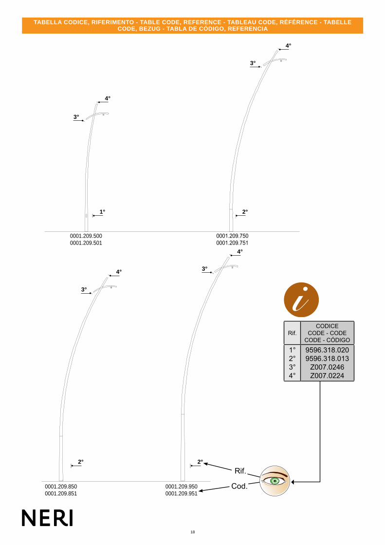
1°2°3°4°
9596.318.0209596.318.013
Z007.0246Z007.0224
TABELLA CODICE, RIFERIMENTO - TABLE CODE, REFERENCE - TABLEAU CODE, RÉFÉRENCE - TABELLE CODE, BEZUG - TABLA DE CÓDIGO, REFERENCIA

19
www.neri.biz
G G
GG
H
A D
E F
C
B
I
GB
F
D
E
13°
Prima dell’installazione del palo è consigliato montare il corpo illuminante.1) Predisporre a terra una robusta stuoia per proteggere le parti verniciate. 2) Prima di assemblare il corpo illuminante al palo, è necessario inserire il cavo elettrico all’interno. Misurare quindi la quantità di cavo elettrico necessaria per collegare il corpo illuminante alla morsettiera, alla base del palo (Fig. A). 3) Inserire il cavo elettrico all’interno del palo (Fig. A). 4) Svitare dal corpo illuminante lo speciale attacco separabile in ottone con filettatura 3/4” GAS (G) (Fig. B). 5) Avvitare l’attacco (G) al braccio di sostegno, con apposita chiave fornita in dotazione (Fig. C). 6) Innestare la chiave nella scanalatura interna dell’attacco (G) (Fig. D). 7) Allentare la vite di sicurezza indicata sul sostegno, e serrare alla coppia di 40 Nm l’attacco in ottone (G) (Fig. E). 8) Bloccare avvitando la vite di sicurezza indicata, ed estrarre circa 50-60 cm di cavo elettrico (H) dal sostegno (Fig. F).
Before commencing installation of the post it is advisable to install the light fixture.1) PLay a sturdy mat on the ground to protect the painted parts. 2) Pass the power cable through the post before installing the light fixture. Measure the quantity of cable needed to connect the light fixture to the terminal at the base of the post (Fig. A). 3) Insert the electric cable inside the post (Fig. A). 4) Unscrew the special removable threaded brass 3/4” GAS coupling (G) from the light fixture (Fig. B). 5) Screw the coupling (G) to the support arm using the special wrench provided (Fig. C). 6) Engage the wrench in the groove inside the coupling (G) (Fig. D). 7) Loosen the safety screw indicated on the support and tighten the brass coupling (G) to a torque of 40 Nm (Fig. E). 8) Lock in place by tightening the safety screw indicted and draw out approximately 50-60 cm of cable (H) from the support (Fig. F).
Il est conseillé de monter le corps éclairant avant l’installation du candélabre.1) Étendre sur le sol une robuste natte afin de protéger les parties peintes. 2) Avant d’assembler l’armature d’éclairage au candélabre, il est nécessaire d’introduire le câble électrique à l’intérieur. Mesurer ensuite la quantité de câble électrique nécessaire à connecter l’armature d’éclairage au bornier, à la base du candélabre (Fig. A). 3) Introduire le câble électrique à l’intérieur du candélabre (Fig. A). 4) Dévisser de l’armature d’éclairage le raccord spécial, détachable, en laiton avec filetage 3/4” GAS (G) (Fig. B). 5) Visser le raccord (G) au bras de support, à l’aide de la clé spéciale fournie en dotation (Fig. C). 6) Introduire la clé dans la rainure interne du raccord (G) (Fig. D). 7) Desserrer la vis de sécurité indiquée sur le support, et serrer à un couple de 40 Nm le raccord en laiton (G) (Fig. E). 8) Bloquer en serrant la vis de sécurité indiquée, et extraire environ 50-60 cm de câble électrique (H) du support (Fig. F).
Vor der Installation des Masts sollte der Leuchtkörper montiert werden.1) Die lackierten Teile auf einer robusten Matte ablegen, damit sie nicht beschädigt werden. 2) Vor der Montage des Leuchtkörpers auf den Mast zuerst das Stromkabel einführen. Hierzu die für die Verbindung des Leuchtkörpers mit der Klemmenleiste im Unterteil des Masts erforderliche Kabellänge messen (Abb. A). 3) Das Stromkabel in den Mast einführen (Abb. A). 4) Den lösbaren Spezialanschluss aus Messing mit Gewinde 3/4” GAS (G) vom Leuchtkörper schrauben (Abb. B). 5) Den Anschluss (G) an den Tragarm schrauben; hierzu den mitgelieferten Schraubenschlüssel verwenden (Abb. C). 6) Den Schraubenschlüssel in die Nut im Anschluss (G) einsetzen (Abb. D). 7) Die auf der Stütze angegebene Sicherungsschraube lockern und den Messinganschluss (G) mit einem Anzugsdrehmoment von 40 Nm anziehen (Abb. E). 8) Die angegebene Sicherungsschraube zum Blockieren einschrauben und das Stromkabel (H) rund 50 bis 60 cm aus der Stütze ziehen (Abb. F).
Se recomienda montar el cuerpo de iluminación antes de instalar el poste.1) Colocar en el suelo una estera gruesa para proteger las partes pintadas. 2) Antes de ensamblar el cuerpo de iluminación al poste, es necesario introducir el cable eléctrico dentro. Calcular la cantidad de cable eléctrico que se requiere para conectar el cuerpo de iluminación a la regleta y a la base del poste (Fig. A). 3) Introducir el cable eléctrico dentro del poste (Fig. A). 4) Desenroscar la unión especial de latón con rosca 3/4” GAS (G) del cuerpo de iluminación (Fig. B). 5) Enroscar la unión (G) al brazo de soporte, utilizando la llave incluida en la dotación (Fig. C). 6) Introducir la llave en la ranura interna de la unión (G) (Fig. D). 7) Aflojar el tornillo de seguridad indicado en el soporte y apretar a 40 Nm la unión de latón (G) (Fig. E). 8) Apretar el tornillo de seguridad indicado para bloquear los componentes y extraer aproximadamente 50 - 60 cm de cable eléctrico (H) a través del soporte (Fig. F).
ASSEMBLAGGIO APPARECCHI SOSPESI - ASSEMBLING SUSPENDED EQUIPMENT - ASSEMBLAGE DISPOSITIFS SUSPENDUS - ZUSAMMENBAU HÄNGENDE GERÄTE - ENSAMBLAJE APARATOS SUSPENDIDOS

20
A B C
I
GB
F
D
E
IMPORTANTE - Al termine dell’installazione degli elementi controllare scrupolosamente che le superfici verniciate non abbiano subito danni (Fig. A).Se ciò fosse accaduto provvedere a ritoccare le superfici danneggiate utilizzando la vernice e catalizzatore miscelati, forniti in dotazione per i ritocchi (Fig. B).
NOTA: per l’utilizzo e la miscelazione dei due prodotti attenersi scrupolosamente a quanto riportato sulle etichette degli stessi.
Pulire accuratamente la superficie danneggiata e applicare con un pennellino (Fig. C) una mano di vernice bicomponente; appena la prima mano di vernice tende ad asciugarsi applicare una seconda mano di vernice.
NOTA: utilizzare per i ritocchi esclusivamente prodotti forniti dalla Neri spa.
IMPORTANTE - Verificare circa una volta all’anno lo stato generale delle superfici e intervenire se necessario al ripristino delle parti danneggiate. Durante il controllo verificare il serraggio di tutte le parti fissate con viti/dadi.
IMPORTANT – Once the elements have been installed carefully check that the painted surfaces have not been damaged (Fig. A).
If damage has occurred, touch-up the damaged areas using the mixed paint and catalyst supplied for touch-up work (Fig. B).
NOTE: for use and mixing of the two products comply strictly with the instructions given on the product labels.
Clean the damaged surface carefully and use a brush (Fig. C) to apply a coat of dual component paint; as soon as this first coat shows signs of drying, apply a second coat.
NOTA: for paint touch-ups use exclusively products supplied by Neri s pa.
IMPORTANT - Approximately once a year check the overall condition of surfaces and intervene if necessary to restore damaged parts. During inspection check that all fixing elements (screws/nuts) are securely fastened.
IMPORTANT – À la fin de l’installation des éléments, il est recommandé de contrôler scrupuleusement que les surfaces vernies ne soient pas endommagées (Fig. A).
En cas de dommages aux surfaces vernies il est nécessaire de retoucher les surfaces en utilisant le vernis et le catalyseur mélangés, fournis en dotation pour les retouches (Fig. B).
REMARQUE : pour l’utilisation et le mélange des deux produits il est recommandé de suivre scrupuleusement les indications reportées sur les étiquettes de ces produits.
Nettoyer soigneusement la surface endommagée et appliquer, à l’aide d’un petit pinceau (Fig. C), une couche de vernis bicomposant ; dès que la première couche de vernis tend à sécher, appliquer une deuxième couche de vernis.
NOTA: pour les retouches il est recommandé d’utiliser exclusivement des produits fournis par Neri spa.
IMPORTANT – Vérifier environ une fois par an l’état général des surfaces et intervenir, le cas échéant, afin de rétablir les parties endommagées. Vérifier pendant le contrôle le serrage de tous les composants fixés à l’aide de vis/écrous.
WICHTIG -Nach Abschluss der Installation der Elemente sorgfältig kontrollieren, dass die lackierten Oberflächen nicht beschädigt wurden (Abb. A).Andernfalls müssen die beschädigten Oberflächen mit dem Gemisch aus Lack und Katalysator, die für Ausbesserungen mitgeliefert wurden, ausgebessert werden (Abb. B).
HINWEIS: Beim Mischen und beim Gebrauch der zwei Produkte die Angaben auf den Etiketten der beiden Produkte genau beachten.
Sorgfältig die beschädigte Fläche säubern und mit einem Pinsel (Abb. C) eine Schicht des 2-Komponenten-Lacks auftragen. Sowie die erste Schicht anfängt zu trocknen, sofort eine 2. Schicht auftragen.
HINWEIS: Für Ausbesserungen ausschließlich die von Neri gelieferten Produkte verwenden.
IMPORTANTE - Mindestens einmal jährlich den allgemeinen Zustand der Oberflächen kontrollieren und beschädigte Stellen ausbessern. Bei der Kontrolle auch den Festsitz aller mit Schrauben oder Muttern befestigten Teile kontrollieren.
IMPORTANTE - Al terminar de instalar los elementos, comprobar atentamente que las superficies pintadas no estén dañadas (Fig. A).
Si lo están, retocar la superficie con una mezcla de la pintura y el catalizador para retoques que se incluyen en la dotación (Fig. B).
NOTA: para más información sobre el uso y las proporciones necesarias para mezclar ambos productos, consultar las instrucciones contenidas en las etiquetas de sus envases.
Limpiar a fondo la superficie dañada y aplicar una mano de pintura bicomponente con un pincel (Fig. C); esperar a que la primera mano se seque antes de aplicar la segunda.
NOTA: para retocar las superficies, utilizar exclusivamente los productos suministrados por Neri spa.
IMPORTANTE: Inspeccionar al menos una vez al año el estado general de las superficies y si es necesario reparar las partes dañadas. Comprobar el apriete de todos los componentes fijados con tornillos y tuercas.
14° CONTROLLI FINALI E MANUTENZIONE - FINAL CHECKS AND MAINTENANCE - CONTRÔLES FINALS ET ENTRETIEN ENDKONTROLLEN UND WARTUNG - CONTROLES FINALES Y MANTENIMIENTO