
La presenza italiana in campo internazionale per il coordinamento ...
111
La presenza italiana in campo internazionale per il coordinamento strategico e programmatico nel settore delle Tecnologie di Cattura e Stoccaggio della CO2 (CCS) Giuseppe Girardi Report RdS/2013/227 Agenzia nazionale per le nuove tecnologie, l’energia e lo sviluppo economico sostenibile MINISTERO DELLO SVILUPPO ECONOMICO
Transcript of La presenza italiana in campo internazionale per il coordinamento ...
La presenza italiana in campo internazionale per il coordinamento strategico e
programmatico nel settore delle Tecnologie di Cattura e Stoccaggio della CO2 (CCS)
Giuseppe Girardi
Report RdS/2013/227
Agenzia nazionale per le nuove tecnologie, l’energia e lo sviluppo economico sostenibile MINISTERO DELLO SVILUPPO ECONOMICO
LA PRESENZA ITALIANA IN CAMPO INTERNAZIONALE PER IL COORDINAMENTO STRATEGICO E
PROGRAMMATICO NEL SETTORE DELLE TECNOLOGIE DI CATTURA E STOCCAGGIO DELLA CO2 (CCS)
Giuseppe Girardi (ENEA )
Settembre 2013
Report Ricerca di Sistema Elettrico
Accordo di Programma Ministero dello Sviluppo Economico - ENEA
Piano Annuale di Realizzazione 2012
Area: Cattura e sequestro della CO2 prodotta dall’utilizzo di combustibili fossili
Progetto: Cattura e sequestro della CO2 prodotta dall’utilizzo di combustibili fossili
Obiettivo: Tecnologie per la rimozione permanente della CO2
Responsabile del Progetto:Stefano Giammartini, ENEA
Le attività sono state condotte in stretto raccordo con il Ministero dello Sviluppo Economico, insieme al Ministero dell’istruzione
dell’Università e della Ricerca, al Ministero dell’Ambiente e della tutela del Territorio e del Mare, e al Dipartimento Politiche
Europee della Presidenza del Consiglio dei Ministri.
Hanno collaborato Istituzioni pubbliche e private, in particolare: OGS, RSE, CNR, INGV, svariate Università, ENEL, Sotacarbo,
Carbosulcis, Assocarboni, Osservatorio sulle CCS della Fondazione per lo Sviluppo Sostenibile.
Un grande apprezzamento per il lavoro svolto dai colleghi dell’ENEA impegnati nelle attività di R/S e di divulgazione, e a tecnici e
ricercatori di Sotacarbo.
Un ringraziamento particolare ai Dott. Andrea Corleto e Veronica Tomasetti, contrattisti di ricerca rispettivamente presso
l’Università di Roma la Sapienza e presso l’ENEA, che hanno operato ad altissimo livello per la diffusione delle informazioni e per la
“public acceptance”.
3
Indice
SOMMARIO ......................................................................................................................................................................... 4
1 INTRODUZIONE .......................................................................................................................................................... 5 1.1 LE SCELTE ENERGETICHE PER UNO SVILUPPO SOSTENIBILE ................................................................................................ 5 1.2 IMPIEGHI DEL CARBONE IN SISTEMI INTEGRATI DI POLIGENERAZIONE ................................................................................. 9
2 DESCRIZIONE DELLE ATTIVITÀ SVOLTE E RISULTATI ................................................................................................. 11 2.1 PARTECIPAZIONE AL CSLF (CARBON SEQUESTRATION LEADERSHIP FORUM) ..................................................................... 11 2.2 PARTECIPAZIONE ALLA IEA (INTERNATIONAL ENERGY AGENCY) ..................................................................................... 11 2.3 PARTECIPAZIONE AL GLOBAL CCS INSTITUTE (GCCSI) ................................................................................................. 11 2.4 PARTECIPAZIONE ALLA PIATTAFORMA ZERO EMISSION FOSSIL FUEL POWER PLANTS (ZEP) ................................................. 12 2.5 PARTECIPAZIONE A CCS EII TEAM (INIZIATIVA INDUSTRIALE EUROPEA) DEL SET PLAN (STRATEGIC ENERGY TECHNOLOGIES) .... 12 2.6 PARTECIPAZIONE A EERA (EUROPEAN ENERGY RESEARCH ALLEANCE) ............................................................................ 12 2.7 INIZIATIVE PROGETTUALI INTERNAZIONALI (ENEL, ALSTOM, FOSTER WHEELER) ........................................................ 13 2.8 SUMMER SCHOOL SULLE CCS ................................................................................................................................. 14
3 CONCLUSIONI ........................................................................................................................................................... 17
ABBREVIAZIONI ED ACRONIMI ......................................................................................................................................... 18
ALLEGATI ........................................................................................................................................................................... 19 ALLEGATO 1 - TRANSIZIONE DEL SISTEMA ELETTRICO: SVILUPPO E SOSTENIBILITÀ ........................................................................... 20 ALLEGATO 2 - CURRENT STATUS OF ITALIAN ENERGY STRATEGY, WITH FOCUS ON NATURAL GAS, COAL AND CCS ................................. 32 ALLEGATO 3 - RECOMMENDATIONS FOR RESEARCH TO SUPPORT CCS DEPLOYMENT IN EUROPE BEYOND 2020 ................................... 45 ALLEGATO 4 - CARBON SEQUESTRATION LEADERSHIP FORUM (CSLF) RECOGNIZED PROJECTS AND TASK FORCES ON STORAGE ............... 82
ACCORDO DI PROGRAMMA MSE-ENEA
4
Sommario Nel presente documento sono sinteticamente descritte le attività, ed i risultati più rilevanti, condotte nell’ambito di alcuni organismi internazionali. In particolare si fa riferimento a:
Partecipazione, quale delegato italiano, nel Technical Group del CSLF (Carbon Sequestration Leadership Forum). Il CSLF è un consesso internazionale, nato su iniziativa governativa, che ha la missione di facilitare lo sviluppo e l’applicazione delle tecnologie CCS attraverso collaborazioni internazionali volte a superare i principali ostacoli di ordine tecnico, economico ed ambientale, promuovendo anche la consapevolezza del pubblico nonché sviluppi normativi e finanziari internazionali.
Partecipazione, quale delegato italiano, a organismi della IEA: - Working Party on Fossil Fuels - Implementing Agreement Clean Coal Centre (CCC) - Implementing Agreement Gas and Oil Technologies (GOT)
Partecipazione, quale rappresentante ENEA, al Global Carbon Capture and Storage Institute (GCCSI). Il GCCSI è un’organizzazione nata su iniziativa del Governo australiano il cui obiettivo è mobilitare risorse pubbliche e private per diffondere le tecniche CCS. L’impegno immediato è quello di accelerare l’avvio di oltre venti progetti pilota. E’ in discussione il piano strategico.
Partecipazione, quale Membro italiano, alla piattaforma tecnologica europea ZEP. La piattaforma tecnologica ZEP (Zero Emission Fossil Fuels Power Plants) unisce e rappresenta gli operatori industriali europei impegnati nelle tecnologie CCS; partecipano rappresentanti del mondo della ricerca e vari operatori; è diretta dal un “ministerial group” ed è organizzata in task force. La nostra partecipazione ha consentito di discutere delle priorità di politica energetica italiana e degli aspetti tecnici legati alle esigenze di ricerca e sviluppo e di diminuzione dei costi.
Partecipazione, quale delegato italiano, al CCS-EII Team, team della Iniziativa Industriale Europea (EII) per la cattura, trasporto e stoccaggio della CO2 (CCS) del SET Plan (Strategic Energy technologies). Opera, in particolare, per l’individuazione di strategie europee e sui finanziamenti europei, specialmente quelli per attività di sviluppo e dimostrative. Particolare attenzione è stata posta alla definizione dei nuovi indirizzi di politica europea della ricerca (Horizon 2020)
Partecipazione, quale rappresentante ENEA e coordinatore nazionale, a EERA (European Energy research Alliance) per le tecnologie CCS. E’ un organismo analogo alla piattaforma ZEP ma riunisce gli operatori del mondo della ricerca. Sono stati lanciati Joint Programmes, fra cui quello sulle CCS di cui ENEA è uno dei partner principali
Iniziative progettuali internazionali. Sono stati presi contatti con gli operatori cinesi, nell’ambito di una collaborazione già avviata fra Cina ed ENEL, ed australiani per la costruzione di progetti comuni finanziabili anche da UE; si è proseguito nella partecipazione al progetto ECCSEL; sono stati avviati contatti per collaborazioni con ALSTOM e FOSTER WHEELER.
Summer School sulle CCS. E’ stata avviata la prima edizione di una iniziativa che continuerà in maniera stabile per i prossimi anni, con l’obiettivo di diventare un punto di riferimento internazionale anche attraverso il coinvolgimento diretto di IEA.
5
1 Introduzione Le attività sono inserite nel complesso contesto internazionale nel quale operano governi, istituzioni pubbliche e operatori privati, con l’obiettivo di accelerare lo sviluppo e l’ingegnerizzazione delle tecnologie per l’impiego sostenibile dei combustibili fossili e, in questo ambito, cercare di rendere competitive le tecnologie di cattura e stoccaggio dell’anidride carbonica (CCS) in grado di consentire l’impiego “dei combustibili fossili, specialmente il carbone, con una drastica riduzione delle emissioni di CO2.
Le considerazioni che seguono vogliono fornire un quadro, sintetico ma esaustivo, del quadro internazionale ed europeo nel quale si è operato per rafforzare il ruolo e la presenza italiana in un settore nel quale si gioca una delle sfide più difficili dei prossimi anni, che è quella di accelerare il percorso verso una società “low carbon”; due sono le considerazioni a monte: a) nei prossimi decenni continuerà l’impiego massiccio di combustibili fossili; b) essenziale, per limitare i danni, è riuscire a sviluppare e rendere competitive le tecnologie CCS. E’ una sfida che si gioca a livello globale, che richiede una sempre maggiore e più efficace cooperazione internazionale.
Di quanto detto vi è consapevolezza diffusa in Italia, e ciò ha sostenuto il ruolo svolto di coordinamento a livello nazionale che la presenza in Europa e su scala più ampia ha richiesto: per questo un grande ringraziamento va ai vari operatori industriali e della ricerca, ed ai rappresentanti dei Ministeri coinvolti.
1.1 Le scelte energetiche per uno sviluppo sostenibile Per fronteggiare efficacemente le modificazioni climatiche è necessario un approccio mirato su efficienza e rinnovabili; tuttavia permarrà per i prossimi decenni un ricorso massiccio alle fonti fossili, tendenzialmente il gas nei Paesi sviluppati ed il carbone nei Paesi ad economie emergenti, anche se il quadro è in rapida evoluzione. La transizione verso una economia “decarbonizzata” è un processo complesso e non breve, che vede l’impegno per lo sviluppo e diffusione delle tecnologie “green” ma allo stesso tempo richiede grandi sforzi per rendere l’impiego dei fossili sempre meno dannoso, accompagnandone la riduzione senza traumi occupazionali e sociali. Gli obiettivi climatici, insieme alla necessità di ridurre ulteriormente le emissioni inquinanti, sono strettamente intrecciati con l’obiettivo di uscire dalla crisi economica puntando ad un delta positivo in termini di razionale impiego delle risorse, di lavoro qualificato e stabile, e di aumento della qualità della vita dei cittadini. E’ il senso che diamo al concetto di sviluppo sostenibile, troppo spesso usato in maniera settoriale o settaria, distorta o strumentale: ricerca e innovazione per la competitività del sistema industriale e dell’intero “sistema paese” sono il perno per guardare al futuro, anche prossimo, con ottimismo. Su questo, come in Europa e nei Paesi più forti, dobbiamo investire anche in Italia, operando finalmente quel salto culturale da tempo atteso.
Lo sviluppo sostenibile, introdotto nel rapporto “Our Common Future” del 1987, e definitivamente lanciato alla Conferenza di Rio su ambiente e sviluppo del 1992, mettendo in stretta relazione tre aspetti di fondamentale importanza - quello economico, quello ambientale e quello sociale - evoca un approccio multidisciplinare la cui ultima finalità prevede, fra l’altro, di interrompere il degrado del patrimonio e delle risorse naturali (che di fatto sono esauribili) ed un loro utilizzo più efficiente anche per meglio controllare e ridurre sempre più il carico verso l’ambiente in termini di emissioni in atmosfera. Se prendiamo in considerazione il fattore umano, il traguardo da raggiungere è l’aumento equo del tenore di vita dell’intera popolazione del Pianeta che, guardando al tema energetico, vuol dire sia sicurezza di approvvigionamento delle fonti e disponibilità di elettricità, sia solidità dei sistemi industriali, salvaguardando le risorse naturali e l’ambiente.
Focalizzando l’attenzione sul tema energetico, un importante documento europeo al quale fare riferimento è il noto Libro Verde-Un quadro per le politiche dell’energia e del clima all’orizzonte 2030, presentato lo scorso marzo al Parlamento Europeo e sul quale si sta ancora discutendo.
ACCORDO DI PROGRAMMA MSE-ENEA
6
In esso si affronta il tema della sostenibilità vista come la sintesi tra sostenibilità ambientale, sicurezza degli approvvigionamenti energetici e competitività economico-industriale.
Nello specifico, il tema ambientale ha a che fare con la riduzione delle emissioni in atmosfera, sia di inquinanti che – principalmente - di anidride carbonica, la riduzione del consumo di energia e quindi l’efficienza energetica, ed ovviamente lo sviluppo delle rinnovabili.
Parlando invece di sicurezza degli approvvigionamenti energetici, bisogna guardare alla diversificazione delle fonti di energia, sia per quanto riguarda le regioni d’origine che la logistica. Un altro aspetto da non sottovalutare riguarda la stabilità delle reti e la risoluzione degli attuali problemi legati all’intermittenza e alla variabilità dell’energia elettrica prodotta dalle fonti rinnovabili. Questo richiama quindi l’esigenza di adeguare le infrastrutture.
Infine, la competitività comporta ad esempio l’abbassamento dei prezzi dell’energia, lo sviluppo di nuove tecnologie, la creazione di nuovi posti di lavoro, il sostegno alle politiche industriali ovvero l’aumento dell’efficienza tecnologica.
Negli ultimi decenni il concetto di sviluppo sostenibile è stato spesso strumentalizzato e divulgato in maniera parziale, e ancora oggi vi sono diverse interpretazioni che non rispecchiano appieno il suo senso vero ed il significato che ne danno gli economisti: le reali finalità sono quelle di governare in maniera equilibrata e sinergica le tre complessità del sistema prima citate.
* * * * * * L’Europa ha assunto lo sviluppo sostenibile come riferimento essenziale anche per le politiche energetiche. La Roadmap dell’energia al 2050 pone come target europeo la riduzione entro il 2030 delle emissioni di gas serra del 40% rispetto ai valori del 1990 per poter conseguire una riduzione dell’80-95% entro il 2050, in linea con l’obiettivo concordato a livello internazionale di limitare il riscaldamento globale a 2°C. Ciò a partire dai ben noti Obiettivi 20-20-20 da conseguire entro il 2020:
riduzione del 20% delle emissioni di CO2;
aumento al 20% della quota di fonti rinnovabili nella copertura dei consumi finali ;
riduzione del 20% dell’utilizzo dell’energia / incremento in termini di efficienza.
Elementi essenziali sono da un lato la progressiva diffusione delle rinnovabili e dell’efficienza energetica, dall’altro la gestione ottimale dell’impiego dei fossili – che continueranno ad essere diffusamente utilizzati nel mondo – riducendo drasticamente le emissioni di CO2 ad essi dovute.
Esemplari sono due recenti importanti discorsi del Presidente Obama. Nel primo viene ribadita la volontà degli Stati Uniti di puntare sul gas naturale - ed in particolare sulle enormi riserve del cosiddetto shale gas - dal momento che tale fonte, negli USA, costa molto poco (ad esempio circa un quarto di quanto costa in Europa); non è un caso che già nel 2012 una progressiva sostituzione del carbone con tale fonte decisamente molto meno onerosa, ha consentito un incremento (valutato in un punto) del PIL della Nazione. Parallelamente gli USA si propongono di puntare fortemente anche su efficienza energetica e rinnovabili. Questa politica consentirà all’industria americana di essere più competitiva sul mercato globale dell’impiantistica energetica – basata su fossili e rinnovabili - dei prossimi anni e decenni. Nel secondo intervento è stato lanciato il cosiddetto progetto Africa Power, tramite il quale verranno messi a disposizione del continente africano 14 miliardi di dollari - tra fondi pubblici ed investimenti privati - allo scopo di adeguarne le infrastrutture ed impedire al Paese di seguire le stesse traiettorie inquinanti seguite dall’Occidente. Ne consegue la promozione dello sviluppo di tecnologie USA vendibili sul mercato internazionale, in preparazione di eventuali inasprimenti futuri delle normative internazionali sulle emissioni. Anche in questo caso le scelte effettuate sono dettate da ragioni di competitività sul mercato.
L’aspetto competitività non va quindi sottovalutato né nel settore dei combustibili fossili né in quello delle rinnovabili, in particolare guardando al mercato globale. A tal fine sono indispensabili politiche industriali forti, con anche incentivi per l’innovazione, che possono svolgere una funzione essenziale purché il processo sia ben governato nella sua complessità.
7
Per quanto riguarda l’Italia, un aspetto della complessità è rappresentato dalla inadeguatezza della nostra rete a gestire un carico così importante di energia intermittente: è un problema enorme, che non può essere sottovalutato. Questo si lega alla articolazione del nostro parco di centrali termoelettriche e alla necessità di tenerlo in considerazione per gestire il processo di transizione ad un nuovo assetto della produzione verso una società sempre meno basata sul carbonio: in sintesi, non si può pensare solo alle FER senza tener conto del contesto. Nel nostro Paese, l’inattesa penetrazione delle rinnovabili nella rete, per effetto delle priorità di dispacciamento, ha infatti condotto ad una crisi di diversi impianti termoelettrici, con una sensibile riduzione del loro funzionamento medio annuo. Basti pensare che i parchi termoelettrici a gas di Enel si attestano in media al di sotto delle 2.000 ore annue. Ciò sta comportando una profonda crisi di quel settore, anche occupazionale.
* * * * * Per effetto della politica americana che si è rivolta alle riserve di shale gas, si sono resi disponibili sul mercato internazionale quantitativi di carbone elevatissimi. Conseguenza diretta è stata la diminuzione del costo del carbone in Europa (specialmente in relazione al gas naturale), tant’è che nel 2012 vi è stato un vero e proprio boom nella realizzazione di tali impianti. Considerando inoltre l’attuale andamento di mercato (che dovrebbe mantenersi similare anche nei prossimi anni), è ragionevole pensare che sul piano economico gli impianti a carbone potranno competere con quelli alimentati a gas naturale.
Naturalmente da ciò non discende che il nostro Paese debba puntare maggiormente sul carbone, ma piuttosto è utile mantenere stabile la quota – quasi residuale - di elettricità proveniente da esso, come previsto dalla SEN (Strategia Energetica nazionale). In sintesi, non ha senso pensare ad aumentare il parco impianti a carbone, ma bensì a un retrofitting o sostituzione di quelli vecchi. Per sostenere tale settore bisognerebbe pensare ad interventi di miglioramento tecnologico utili ad abbassare i costi ed ottenere energia più pulita. Due le vie da perseguire: la prima è quella dello sviluppo di tecnologie che siano allo stesso tempo più efficienti e meno inquinanti, le cosiddette HELE – High-Efficiency, Low-Emissions; l’altra è quella costituita dalle CCS – Carbon Capture Storage. Entrambe rappresentano un’opportunità enorme.
Se una delle priorità a livello globale è quella di produrre energia elettrica“pulita” e a basso costo, è necessario puntare – specialmente per noi italiani – alla innovazione degli impianti guardando ai costi di generazione, e alle emissioni (tecnologie HELE e CCS) per mantenere la competitività complessiva del nostro sistema industriale nell’ ambito internazionale: non possiamo permetterci il lusso di perdere anche il settore dell’impiantistica energetica, destinato ad essere profondamente mutato sotto la spinta, appunto, delle tendenze internazionali e delle politiche energetiche praticate da aree strategiche (Cine e India in primis) che continueranno ad impiegare per svariati decenni combustibili fossili ed in particolare carbone.
* * * * *
Riguardo alle tecnologie CCS, al loro impiego in relazione alla generazione elettrica ed alle prospettive di applicazioni industriali, è bene riferirsi ancora allo scenario internazionale.
In primis va detto che l’obiettivo che ci si pone è quello di rendere utilizzabili industrialmente le CCS a partire dal 2030. Per questo occorrono non solo molta ricerca e sviluppo, ma anche impianti dimostrativi di scala significativa, dotati di queste tecnologie, affiancati ovviamente da un’opportuna normativa ed interventi politici: da quest’ultimo punto di vista sono d’esempio la Carbon Tax norvegese sulle emissioni di carbonio piuttosto che l’ETS europeo, ma ovviamente è necessaria una normazione internazionale abbastanza omogenea.
E’ necessario ribadire che in un’ottica di raggiungimento dei citati target europei di riduzione delle emissioni al 2050, occorrono comunque interventi “a ventaglio”, che consentano in primo luogo di incrementare le rinnovabili e l’efficienza energetica ma anche di introdurre la tecnologia delle CCS che può contribuire per almeno il 20% al conseguimento dell’obiettivo. Occorre, però, superare gli attuali limiti, ovvero quello dei costi e quello dell’accettabilità sociale.
ACCORDO DI PROGRAMMA MSE-ENEA
8
Rispetto al primo limite, come emerso da un recente studio effettuato dalla piattaforma tecnologica europea ZEP (Zero Emissions Fossil Fuel Power Plants), il costo medio per catturare e stoccare l’anidride carbonica, varia dai 60-70$ agli oltre 100$ a tonnellata di CO2. L’obiettivo è quello di ridurlo a 40$. Questo sarà possibile solo grazie allo sviluppo di sistemi più efficienti, attraverso attività di ricerca e sviluppo e attraverso la realizzazione di impianti industriali pilota e dimostrativi di grande taglia.
Sul fronte invece dell’accettazione sociale le maggiori preoccupazioni riguardano le possibili conseguenze di eventuali fuoriuscite incontrollate della CO2 iniettata nel sottosuolo.
Va detto in tal senso che molte sono le conoscenze già acquisite sia da un punto di vista tecnologico (messa a punto di sistemi di monitoraggio) che geologico. Già da tempo si utilizza infatti l’anidride carbonica per aumentare la produttività dei pozzi di petrolio avvalendosi della nota tecnologia EOR - Enhanced Oil Recovery, e sono in corso nel mondo moltissime iniziative industriali volte a dimostrare la fattibilità di tali applicazioni in giacimenti acquiferi salini e pozzi depleti.
Il punto centrale è avviare una vera ed efficace politica di “partecipazione”, che coinvolga i cittadini e le Istituzioni locali, basata su una azione di informazione seria ed autorevole sulle tecnologie e tutte le relative implicazioni; occorre riuscire a comunicare e a dialogare con la popolazione e gli amministratori, senza reticenze, senza negare i problemi e allo stesso tempo dando conto delle garanzie di sicurezza basate sulle conoscenze e sulle precauzioni che si possono e si devono adottare: è l’unica strada, non solo in questo settore specifico, per poter dare vita a nuovi investimenti e ad un numero maggiore di applicazioni dimostrative.
Nel nostro Paese è comunque già in essere un’importante iniziativa in questo settore, che spazia dalla ricerca e sviluppo, alla dimostrazione su scala industriale, fino alla formazione-informazione e crescita dell’accettabilità sociale. E’ un’iniziativa lanciata nell’area del Sulcis, nel territorio Sud Ovest della Sardegna, che tra l’altro si presta molto bene allo stoccaggio dell’anidride carbonica in quanto è una zona non sismica e presenta formazioni acquifere saline, considerate le più idonee per lo stoccaggio della CO2, sovrastate da strati di carbone non utilizzabili. Tutte queste condizioni consentono di sperimentare simultaneamente due differenti tecnologie di stoccaggio: l’iniezione in acquiferi salini e lo stoccaggio in giacimenti non sfruttabili di carbone – ECBM: Enhanced Coal Bed Methane – tramite il quale si pompa CO2 negli strati di carbone liberando il metano lì presente. Elemento non trascurabile è l’assenza di forti ostilità sociali e politiche, trovandoci in un’area che storicamente ha impostato la sua attività economica sul carbone e che attualmente è affetta da una clamorosa deindustrializzazione, e la cui popolazione è pertanto maggiormente aperta ad accettare – addirittura a promuovere - impianti di questo tipo.
Su tale base il Governo ha stipulato un accordo con la Regione Sardegna, per la realizzazione di un polo tecnologico per il carbone pulito. Caratteristica essenziale del piano è di operare sui tre pilastri che portano alla innovazione industriale: studi e sperimentazione su attrezzature da laboratorio, sviluppo delle tecnologie con attività su apparati pilota di taglia rilevante, e qualificazione e trasferimento mediante realizzazione ed esercizio di impianti industriali dimostrativi. Tale piano si basa sull’esperienza e le infrastrutture già presenti presso Sotacarbo e sugli studi in corso relativi a svariate tecnologie di cattura e di stoccaggio della CO2, sulla produzione di nuovi combustibili liquidi e gassosi a partire da carbone, e su sistemi integrati di “poligenerazione”. L’obiettivo è valorizzare e promuovere l’industria italiana e lo sviluppo delle tecnologie per consentire al settore manifatturiero termoelettrico di competere sul mercato internazionale: anche per questo si pensa alla realizzazione di un impianto pilota di 50 MWth basato sulla tecnologia di ossicombustione in pressione sviluppata nel nostro Paese. Nel campo dello stoccaggio, poi, è previsto un ampio programma volto alla sperimentazione e caratterizzazione del sito Sulcis per l’iniezione di CO2 in “acquiferi salini” e in strati di carbone con possibile estrazione di metano (la citata tecnologia ECBM). E’ un’opportunità enorme quella di
9
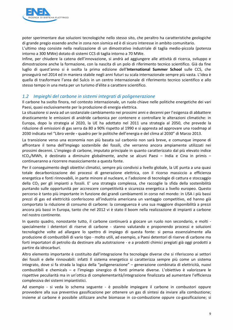
poter sperimentare due soluzioni tecnologiche nello stesso sito, che peraltro ha caratteristiche geologiche di grande pregio essendo anche in zona non sismica ed è di sicuro interesse in ambito comunitario. L’ultimo step consiste nella realizzazione di un dimostrativo industriale di taglia medio-piccola (potenza intorno a 300 MWe) dotato di sistemi CCS di taglia intorno a 70 MWe. Infine, per chiudere la catena dell’innovazione, si andrà ad aggiungere alle attività di ricerca, sviluppo e dimostrazione anche la formazione, con la nascita di un polo di riferimento tecnico scientifico. Già da fine luglio di quest’anno si è svolta la prima edizione dell’International Summer School sulle CCS, che proseguirà nel 2014 ed in maniera stabile negli anni futuri su scala internazionale sempre più vasta. L’idea è quella di trasformare l’area del Sulcis in un centro internazionale di riferimento tecnico scientifico e allo stesso tempo in una meta per un turismo d’élite a carattere scientifico.
1.2 Impieghi del carbone in sistemi integrati di poligenerazione Il carbone ha svolto finora, nel contesto internazionale, un ruolo chiave nelle politiche energetiche dei vari Paesi, quasi esclusivamente per la produzione di energia elettrica. La situazione si avvia ad un sostanziale cambiamento nei prossimi anni e decenni per l’esigenza di abbattere drasticamente le emissioni di anidride carbonica per contenere e controllare le alterazioni climatiche: in Europa, dopo la strategia al 2020, la UE ha adottato nel 2011 una strategia al 2050, che prevede la riduzione di emissioni di gas serra da 80 a 90% rispetto al 1990 e si appresta ad approvare una roadmap al 2030 indicata nel “Libro verde - quadro per le politiche dell’energia e del clima al 2030” di Marzo 2013.
La transizione verso una economia non più basata sul carbonio non sarà breve, e comunque impone di affrontare il tema dell’Impiego sostenibile dei fossili, che verranno ancora ampiamente utilizzati nei prossimi decenni. L’impiego di carbone, imputato principale in quanto caratterizzato dal più elevato indice tCO2/MWh, è destinato a diminuire globalmente, anche se alcuni Paesi – India e Cina in primis – continueranno a ricorrere massicciamente a questa fonte.
Per il conseguimento degli obiettivi climatici, sempre più condivisi a livello globale, la UE punta a una quasi totale decarbonizzazione dei processi di generazione elettrica, con il ricorso massiccio a efficienza energetica e fonti rinnovabili, in parte minore al nucleare, e l’adozione di tecnologie di cattura e stoccaggio della CO2 per gli impianti a fossili. E’ una strategia complessa, che raccoglie la sfida della sostenibilità puntando sulle opportunità per accrescere competitività e sicurezza energetica a livello europeo. Questo percorso è tanto più importante in funzione dei grandi cambiamenti in corso nel mondo: in USA i più bassi prezzi di gas ed elettricità conferiscono all’industria americana un vantaggio competitivo, ed hanno già comportato la riduzione di consumo di carbone: la conseguenza è una sua maggiore disponibilità a prezzi ancora più bassi in Europa, tanto che nel 2012 vi è stato il boom nella realizzazione di impianti a carbone nel nostro continente.
In questo quadro, nonostante tutto, il carbone continuerà a giocare un ruolo non secondario, e molti - specialmente i detentori di riserve di carbone - stanno valutando e proponendo processi e soluzioni tecnologiche volte ad allargare lo spettro di impiego di questa fonte: si pensa essenzialmente alla produzione di combustibili di vario tipo - molto utili, ad esempio, a Paesi detentori di riserve di carbone ma forti importatori di petrolio da destinare alla autotrazione - e a prodotti chimici pregiati già oggi prodotti a partire da idrocarburi.
Altro elemento importante è costituito dall’integrazione fra tecnologie diverse che si riferiscono ai settori dei fossili e delle rinnovabili: infatti Il sistema energetico si caratterizza sempre più come un sistema integrato, dove si fa strada la logica della “poligenerazione” – generazione combinata di elettricità, nuovi combustibili e chemicals – e l’impiego sinergico di fonti primarie diverse. L’obiettivo è valorizzare le rispettive peculiarità ma in un’ottica di complementarità/integrazione finalizzata ad aumentare l’efficienza complessiva dei sistemi impiantistici.
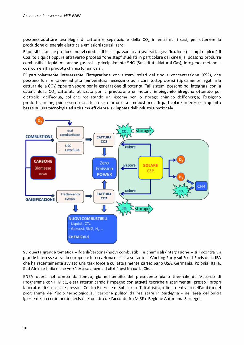
Ad esempio - si veda lo schema seguente - è possibile impiegare il carbone in combustori oppure provvedere alla sua preventiva gassificazione per ottenere un gas di sintesi da inviare alla combustione; insieme al carbone è possibile utilizzare anche biomasse in co-combustione oppure co-gassificazione; si
ACCORDO DI PROGRAMMA MSE-ENEA
10
possono adottare tecnologie di cattura e separazione della CO2 in entrambi i casi, per ottenere la produzione di energia elettrica a emissioni (quasi) zero.
E’ possibile anche produrre nuovi combustibili, sia passando attraverso la gassificazione (esempio tipico è il Coal to Liquid) oppure attraverso processi “one step” studiati in particolare dai cinesi; si possono produrre combustibili liquidi ma anche gassosi – principalmente SNG (Substitute Natural Gas), idrogeno, metano – così come altri prodotti chimici (chemicals).
E’ particolarmente interessante l’integrazione con sistemi solari del tipo a concentrazione (CSP), che possono fornire calore ad alta temperatura necessario ad alcuni sottoprocessi (tipicamente legati alla cattura della CO2) oppure vapore per la generazione di potenza. Tali sistemi possono poi integrarsi con la catena della CO2 catturata utilizzata per la produzione di metano impiegando idrogeno ottenuto per elettrolisi dell’acqua, col che realizzando un sistema per lo storage chimico dell’energia; l’ossigeno prodotto, infine, può essere riciclato in sistemi di ossi-combustione, di particolare interesse in quanto basati su una tecnologia ad altissima efficienza sviluppata dall’industria nazionale.
Su questa grande tematica – fossili/carbone/nuovi combustibili e chemicals/integrazione – si riscontra un grande interesse a livello europeo e internazionale: si cita soltanto il Working Party sui Fossil Fuels della IEA che ha recentemente avviato una task force a cui attualmente partecipano USA, Germania, Polonia, Italia, Sud Africa e India e che verrà estesa anche ad altri Paesi fra cui la Cina.
ENEA opera nel campo da tempo, già nell’ambito del precedente piano triennale dell’Accordo di Programma con il MiSE, e sta intensificando l’impegno con attività teoriche e sperimentali presso i propri laboratori di Casaccia e presso il Centro Ricerche di Sotacarbo. Tali attività, infine, rientrano nell’ambito del programma del “polo tecnologico sul carbone pulito” da realizzare in Sardegna - nell’area del Sulcis iglesiente - recentemente deciso nel quadro dell’accordo fra MiSE e Regione Autonoma Sardegna
11
2 Descrizione delle attività svolte e risultati
2.1 Partecipazione al CSLF (carbon Sequestration Leadership Forum) Il CSLF è un consesso internazionale, istituito a livello ministeriale, che attualmente coinvolge 24 nazioni più l’Unione Europea, che rappresentano oltre 3.5 miliardi di persone, pari a circa il 60% della intera popolazione mondiale. La missione del CSLF consiste nel facilitare lo sviluppo e l’applicazione delle tecnologie CCS attraverso collaborazioni internazionali volte a superare i principali ostacoli di ordine tecnico, economico ed ambientale, promuovendo anche la consapevolezza del pubblico nonché sviluppi normativi e finanziari internazionali. Il CSLF ha ormai assunto un ruolo fondamentale nel panorama internazionale, ed ha operato in stretta sinergia con l’Agenzia Internazionale per l’Energia (IEA) nella stesura di documenti strategici per vari incontri, quali il G8-Energia di Roma dove, si ricorda, il nostro Paese ha sottoscritto importanti accordi di collaborazione anche con il governo USA. La partecipazione assidua dell’Italia a tutte le riunioni del CSLF ha consentito al nostro Paese di mantenere uno stretto contatto con tutti i principali attori internazionali e di promuovere le iniziative italiane. In particolare è stato ospitato in Italia il meeting annuale del CSLF, organizzato a Roma da ENEA. Sono stati affrontati e discussi gli sviluppi delle politiche energetiche nei vari Paesi, e si è proceduto ad un aggiornamento della road-map sulle CCS.
Si è, poi, partecipato ad un importante meeting internazionale organizzato da “CGS Europe” che associa i principali organismi di ricerca e industriali operanti nel settore dello stoccaggio della CO2: in tale ambito abbiamo partecipato in rappresentanza del CSLF, presentando i principali progetti sostenuti da CSLF
2.2 Partecipazione alla IEA (International Energy Agency) Di particolare rilievo è stata la partecipazione al Working Party on Fossil Fuels (WPFF), organismo di vertice al quale, fra l’altro, si riferiscono I vari Implementing Agreement. In questo ambito ci è stato chiesto di presentare la situazione energetica in Italia, con riferimento al gas, al carbone e alle CCS. In questo ambito, ancora, è stato lanciato un nuovo Implementing Agreement sulle Tecnologie del gas e olio (GOT), a cui l’Italia partecipa per ora come osservatore in attesa di una adesione formale.
E’ proseguito il lavoro all’interno dell’Implementing Agreement CCC (Clean Coal Center), nel quale ha assunto un ruolo primario la tematica delle CCS: ciò è dovuto alla consapevolezza – unanimemente condivisa – che nei prossimi decennia il ricorso ai fossili sarà ancora massiccio e determinante, e l’unica via per un loro impiego il più possibile sostenibile sta nell’applicazione delle tecnologie CCS.
Quello di IEA è, dunque, un consesso cruciale al quale l’italia ha partecipato presentando le iniziative nazionali e confrontandole con quelle degli altri paesi. Il progetto SULCIS, recentemente lanciato dal MISE, rappresenta un importante riferimento anche in questo prestigioso consesso.
2.3 Partecipazione al Global CCS Institute (GCCSI) Al G8 Ambiente, tenutosi nell’aprile 2008 a Siracusa, è stato sottoscritto, nell’ambito dell’Intesa italo-australiana per la cooperazione nello sviluppo delle tecnologie CCS, un “Memorandum of Understanding” tra ENEL e il ministro australiano dell’Agricoltura, della Pesca e delle Foreste, che prevede l’adesione di ENEL come socio fondatore al Global Carbon Capture and Storage Institute (GCCSI). Il GCCSI è un’organizzazione nata su iniziativa del Governo australiano il cui obiettivo è mobilitare risorse pubbliche e private per diffondere le tecniche CCS; l’impegno immediato è quello di accelerare l’avvio progetti pilota e dimostrativi. Hanno aderito al GCCSI tutti i Paesi dell’Europa maggiormente impegnati nello sviluppo delle tecnologie CCS, oltre a Stati Uniti, Canada, Messico, Sud-Africa ed altri Paesi dell’Oceania e dell’Asia. L’adesione al GCCSI ci ha consentito di entrare in un circuito internazionale che sta assumento un ruolo di leadership assoluta quale stakeholder “indipendente”, di acquisire informazioni anche su progetti extra-europei; sono state acquisite le condizioni per partecipare a pieno titolo alla rete di alleanze tecnologiche e
ACCORDO DI PROGRAMMA MSE-ENEA
12
industriali che nasceranno nell’ambito dell’organizzazione, di essere costantemente aggiornata sugli sviluppi normativi e regolamentari del CCS nel mondo e, infine, di valutare i risultati delle varie iniziative di comunicazione attivate dagli altri membri.
Si è partecipato alla elaborazione del nuovo piano strategico, che vede un ulteriore sviluppo del GCCSI.
2.4 Partecipazione alla Piattaforma Zero Emission Fossil Fuel Power Plants (ZEP) La piattaforma tecnologica ZEP (fondata nel 2005, unisce e rappresenta gli operatori industriali europei impegnati nelle tecnologie CCS; partecipano rappresentanti dei Governi nazionali, del mondo della ricerca e di organizzazioni terze. Svolge un ruolo essenziale per la definizione delle strategie europee. I membri della Task Force Tecnology (TFT), oltre a incontrarsi periodicamente per la messa a punto degli indirizzi da suggerire alla Commissione – in funzione delle attività di finanziamento di progetti di ricerca e dimostrazione - hanno operato, usando ampiamente lo strumento delle riunioni via Skype, per l’aggiornamento di documenti quali la road-map e il nuovo piano strategico sulle CCS: In particolare si è partecipato ai lavori di elaborazione del documento su <recommendations for research to support CCS deployment in Europe beyond 2020 – update on CO2 capture>. la partecipazione al Ministerial Group di ZEP ci ha consentito di cionfrontare, anche in questo ambito, politiche e priorità del nostro Paese. Ci è stato chiesto di ospitare la seconda riunione annuale del ministerial meeting, ciò che avverrà a novembre di quest’anno presso la sede ENEA di Brussels.
2.5 Partecipazione a CCS EII Team (Iniziativa industriale Europea) del SET Plan (Strategic Energy Technologies)
E’ un gruppo costituito da un rappresentante per ciascuno Stato membro, da alcuni rappresentanti della piattaforma ZEP e di EERA, e da alcuni stakeholder. Svolge un ruolo cruciale per la definizione degli indirizzi attuativi delle varie iniziative previste in ambito SET Plan, cercando di armonizzare le attività di ricerca, pilota e dimostrative, e allo stesso tempo allargando occasioni di cooperazione fra gli Stati. In particolare sono state concordate e trasmesse alla Commissione gli indirtizzi consigliati per il prossimo programma in ambito Horizon 2020. L’Italia, che di fatto ha abbandonato il progetto ENEL di Porto Tolle, è comunque in campo con il nuovo progetto SULCIS.
2.6 Partecipazione a EERA (European Energy Research Alleance) EERA E’ un organismo per molti aspetti analogo alla piattaforma ZEP ma riunisce gli operatori del mondo della ricerca sulle tematiche ritenute cruciali, e fra esse le CCS. Il lavoro svolto si è concentrato sulla definizione del Joint Programme (JP), un ampio programma di ricerca con obiettivi nel medio-lungo periodo costruito con il concorso di un numero rilevante di organismi dei vari Paesi che hanno concordato di armonizzare programmi in corso e già finanziati. L’ENEA, insieme ai suoi associati (varie Università) ha proposto il pacchetto delle attività svolte nell’ambito dell’ADP MISE-ENEA, con ciò valorizzando tali attività e creando opportunità per future collaborazioni. E’ da rilevare che il ruolo di EERA sarà cruciale nei prossimi anni in quanto si prevede che, in ambito Horizon 2020, i finanziamenti comunitari verranno assegnati non più a singoli progetti ma a programmi complessivi, come appunto i JPs: è stato, dunque, essenziale essere fra i promotori dell’iniziativa, caratterizzando l’ENEA come uno fra i principali partner del JP. Nell’assemblea generale di Giugno 2012 si è concordato di aggiornare il JP entro l’anno, anche a seguito della adesione di altri membri. I lavori sono proseguiti con l’aggiornamento del programma congiunto, e con l’interazione con UE per le priorità di Horizon 2020. La prossima riunione dall’assemblea dei membri del Joint programme si terrà a Dicembre presso la sede ENEA di Roma.
13
2.7 Iniziative progettuali internazionali (ENEL, ALSTOM, FOSTER WHEELER) Sono stati presi contatti con gli operatori cinesi, nell’ambito di una collaborazione già avviata fra Cina ed ENEL, ed australiani per la costruzione di progetti comuni finanziabili anche da UE.
Si è proseguito nella partecipazione al progetto ECCSEL, un programma (FP7-Research Infrastructures) volto alla realizzazione di grandi infrastrutture di ricerca europee in vari settori, contando su quanto di rilevante già esiste ed è operativo e che, però, va ampliato ed integrato a fronte di finanziamenti comunitari e nazionali. Il progetto riunisce i Centri di Eccellenza europei sulle tematiche CCS ed è coordinato dall’istituto norvegese NTNU con la partecipazione di organismi da Polonia, Francia, Germania, Spagna, UK, Grecia, Olanda, Svizzera e Italia. Per l’Italia partecipano OGS (per la tematica dello stoccaggio di CO2) ed ENEA (relativamente alle tecnologie impiantistiche di cattura, integrazione ed analisi energetico-ambientali). Importanti ricadute consistono nell’opportunità di valorizzare – utilizzando fondi comunitari - le infrastrutture esistenti sia presso il Centro ENEA-Casaccia che presso l’area sperimentale di Sotacarbo, e l’inserimento a pieno titolo nel network europeo sulle CCS.
Sono stati avviati contatti per collaborazioni con ALSTOM e FOSTER WHEELER relative alla produzione di combustibili liquidi e gassosi in processi innovativi legati anche alla cattura ed impiego della CO2.
E’ stato organizzato il meeting internazionale Tecnologie Zero Emission per la competitività, lo sviluppo industriale e l’ambiente - Il progetto CCS Sulcis: prospettive, realizzazione, ricadute produttive e territoriali; si è svolto il 21 novembre 2012 presso il Centro Ricerche Sotacarbo, Grande Miniera Serbariu—Carbonia (CI) con l’obiettivo di rilanciare il “progetto Sulcis” sulla base di considerazioni unanimemente condivise che si riportano sinteticamente.
- Obiettivi della politica energetica europea sono la riduzione delle emissioni di gas con effetto serra, la sicurezza degli approvvigionamenti e la competitività delle imprese. Il Pacchetto clima-energia del 2009 e la Road Map per l’anno 2050 definiscono le linee guida e gli strumenti per l’attuazione. La nuova Strategia Energetica Nazionale confermando le scelte europee, propone azioni per un’energia più competitiva e sostenibile.
- In questo quadro hanno un ruolo fondamentale le tecnologie di cattura e stoccaggio dell’anidride carbonica (CCS), che permettono di separare l’anidride carbonica (CO2) generata dai processi industriali e di confinarla attraverso lo stoccaggio nel sottosuolo in formazioni geologiche profonde, oppure mediante altri metodi di natura biologica e chimica.
- Le tecnologie CCS sono essenziali su scala mondiale per la stabilizzazione e la riduzione delle emissioni di gas serra al fine di evitare il surriscaldamento dell’atmosfera del pianeta.
- Le tecnologie CCS modificano in modo radicale la costruzione dei futuri impianti termoelettrici (a carbone e a gas naturale) e potranno trovare impiego anche in altri settori caratterizzati da processi industriali che producono grandi emissioni di CO2, come la fabbricazione del cemento, la siderurgia, e la petrolchimica.
- Tuttavia le tecnologie CCS oggi disponibili devono essere dimostrate su scala significativa in vista di una loro estesa commercializzazione e impiego.
- Lo sviluppo delle tecnologie CCS può offrire, all’industria nazionale, l’opportunità di svilupparsi e di competere nel settore delle grandi infrastrutture energetiche e dei processi industriali fortemente emettitori di CO2.
- Per il nostro paese è essenziale puntare sull’innovazione in un settore importante come quello energetico, uno fra i pochissimi sui quali si può costruire una filiera tecnologica italiana.
Il Convegno ha inteso offrire un’occasione di incontro e di proposta sul progetto CCS Sulcis, sulle opportunità e occasioni per nuove collaborazioni tecnologiche e industriali, sulle ricadute produttive del Progetto e sulle opportunità di investimento. Hanno partecipato, fra gli altri, rappresentanti di IEA, Global CCS Institute, WEC, Foster Wheeler, oltre a rappresentanti delle Istituzioni (in primis MiSE) e di organismi di ricerca.
ACCORDO DI PROGRAMMA MSE-ENEA
14
2.8 Summer School sulle CCS ENEA, insieme a Università di Cagliari-Dipartimento di Ingegneria Meccanica, Chimica e dei Materiali e
Sotacarbo, ha organizzato la prima edizione della “Sulcis Summer School on CCS Technologies” che si è
svolta presso il centro sperimentale di Sotacarbo dal 23 al 26 Luglio 2013.
E’ una iniziativa di valenza internazionale che si pone l’obiettivo di attivare una sede stabile di
approfondimento degli argomenti e delle problematiche relative al campo delle tecnologie di cattura e
stoccaggio della CO2 (CCS), e si rivolge a studenti universitari della laurea magistrale (o corsi equipollenti) e
del dottorato di ricerca provenienti da diversi percorsi formativi, oltre che a operatori ed esperti di
impiantistica energetica, al fine di promuovere la loro partecipazione attiva in questo settore.
La cattura e lo stoccaggio dell’anidride carbonica sono unanimemente considerati essenziali per poter
conseguire l’obiettivo della drastica riduzione delle emissioni di CO2 in atmosfera nei prossimi anni e
decenni. Attualmente, il potenziale delle tecnologie CCS è in fase di studio in tutto il mondo con più di 100
progetti e conferenze internazionali che servono come piattaforme per lo scambio dei risultati di tali
attività tra gli esperti. Per la diffusione di applicazioni su larga scala è tuttavia necessario ampliare la base di
conoscenze nei paesi industrializzati e in via di sviluppo, in particolare a livello accademico. I corsi di
formazione o scuole estive sono un modo di contribuire a questo obbiettivo, promuovendo e sostenendo la
diffusione delle conoscenze sul potenziale di CCS a studenti ed operatori di tutto il mondo.
Questa “prima edizione” della scuola estiva ha una durata di tre giorni, più un quarto destinato alla visita
della miniera, e prevede lo svolgimento di seminari e di attività formative e la costituzione di gruppi di
discussione guidati da esperti nel campo delle CCS. Al termine del percorso formativo gli studenti hanno
acquisito un'ampia panoramica delle tematiche e delle inerenti problematiche che circondano lo sviluppo
tecnologico e l'implementazione delle tecnologie CCS e avranno contribuito alla realizzazione di una rete di
contatti utili per lo sviluppo di attività nel settore. Il percorso formativo si concluderà con la redazione, da
parte di ciascuno “studente”, di un elaborato finale per l’accertamento delle conoscenze acquisite.
L’Università di Cagliari, infine, riconoscerà crediti formativi agli studenti che avranno frequentato con
profitto l’intero pacchetto di lezioni.
L’iscrizione alla scuola è gratuita. La docenza è stata affidata a professori universitari ed esperti provenienti
dal mondo della ricerca e dal settore industriale, con una presenza significativa in particolare di esponenti
dell’ENEA, dell’Università di Cagliari e di Sotacarbo.
L’iniziativa proseguirà - in maniera più vasta e con un forte connotato internazionale - con cadenza annuale
a partire dal 2014, e si pone l’obiettivo di attivare una sede stabile di formazione/informazione rivolta
anche agli amministratori locali e agli stakeholder, locali e nazionali, per favorire il dialogo, accrescere la
fiducia in tali tecnologie, e contribuire quindi alla accettabilità sociale.
Tale iniziativa, infine, comporta implicazioni più generali volte anche ad attivare un “turismo scientifico” di
qualità nell’area del Sulcis.
E’ stato attivato il sito http://www.sulcisccssummerschool.it da parte degli esperti ENEA, con importanti
funzionalità da sviluppare immediatamente come quella di attivare un programma di e-learning su
piattaforma ENEA.
Partner coinvolti
L' Istituto Nazionale di Oceanografia e di Geofisica Sperimentale - OGS è un ente pubblico di ricerca che svolge, promuove, coordina studi e ricerche rivolti alla conoscenza della Terra e delle sue risorse, allo sviluppo di nuove tecnologie applicative ed interpretative nei campi delle scienze del mare, dell'ambiente, della sismicità , delle risorse minerarie ed alla migliore utilizzazione del territorio. La natura e la missione dell´OGS sono definite nella legge n.399/1989 di riordino
15
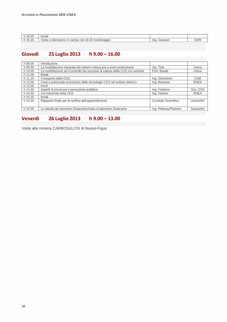
PROGRAMMA
Martedì 23 Luglio 2013 h 9.00 – 16.00
h 09.00 Introduzione Prof.Cau/Girardi/Porcu UniCA/ENEA
h 09.30 Inquadramento generale delle tecnologie CCS Prof. Cau / Ing. Girardi Unica/ENEA
h 10.00 Fonti di CO2 e bilancio delle emissioni Prof. Cau Unica
h 11.00 break
h 11.15 Cattura della CO2: le diverse tecnologie precomb, post comb e oxyfuel Prof. Cocco/Ing. Tola Unica
h 12.00 Storage della CO2: il contributo del progetto Sulcis Ing. Porcu Sota/Carbosulcis
h 13.00 lunch
h 14.30 Lo studio e lo sviluppo di tecnologie CCS nell’esperienza e nelle attività ENEA
Ing. Deiana ENEA
h 15.00 La tecnologia ITEA: ossicombustione pressurizzata flameless Ing.Bassignano/Malavasi ITEA
h 15.30 Le attività della Piattaforma Pilota Sotacarbo Ing. Maggio Sotacarbo
h 16.00 break
h 16.15 Visita agli impianti Sotacarbo Ing. Calì Sotacarbo
Mercoledì 24 Luglio 2013 h 9.00 – 16.00
h 09.00 Le tecnologie di stoccaggio della CO2 Ing. Persoglia OGS
h 09.30 Valutazione del potenziale di stoccaggio nei siti idonei allo storage della CO2 Dott. Donda OGS
h 10.00 Normativa europea e nazionale: lo stato di attuazione del DLgs162/2011 Dott. Panei MiSE
h 11.00 break
h 11.15 Linee guida per monitoraggio geochimico dei siti idonei allo storage della CO2 Prof. Lombardi UniRoma1
h 12.00 Caratterizzazione reservoir carbonatico per lo stoccaggio della CO2 nel Sulcis Prof. Fais Unica
h 13.00 lunch
h 14.30 L’esperienza Carbosulcis Ing. Podda Carbosulcis
h 15.00 Sistemi innovativi di cattura della CO2 Ing. De Angelis UniBO
h 15.30 Le attività di monitoraggio della CO2 c/o l’area del Sulcis Prof. Lombardi UniRoma1
dell´Osservatorio Geofisico Sperimentale e nel decreto legislativo n.381/1999 con cui esso è stato trasformato in istituto nazionale.
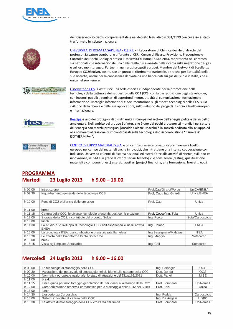
UNIVERSITA' DI ROMA LA SAPIENZA - C.E.R.I. - Il Laboratorio di Chimica dei Fluidi diretto dal professor Salvatore Lombardi e afferente al CERI, Centro di Ricerca Previsione, Prevenzione e Controllo dei Rischi Geologici presso l’Università di Roma La Sapienza, rappresenta nel contesto sia nazionale che internazionale una delle realtà più avanzate della ricerca sulla migrazione dei gas e sul loro monitoraggio. Partner in numerosi progetti europei, Membro del Network di Eccellenza Europeo CO2GeoNet, costituisce un punto di riferimento nazionale, oltre che per l’attualità delle sue ricerche, anche per la conoscenza derivata da una banca dati sui gas del suolo in Italia, che è unica nel suo genere.
Osservatorio CCS - Costituisce una sede esperta e indipendente per la promozione della tecnologia della cattura e del sequestro della CO2 (CCS) con la partecipazione degli stakeholder, con incontri pubblici, seminari di approfondimento, attività di comunicazione, formazione e informazione. Raccoglie informazioni e documentazione sugli aspetti tecnologici della CCS, sullo sviluppo della ricerca e delle sue applicazioni, sullo sviluppo dei progetti in corso a livello europeo e internazionale.
Itea Spa è uno dei protagonisti più dinamici in Europa nel settore dell’energia pulita e del rispetto ambientale. Nell’ambito del gruppo Sofinter, che è uno dei pochi protagonisti mondiali nel settore dell’energia con marchi prestigiosi (Ansaldo Caldaie, Macchi) è la società dedicata allo sviluppo ed alla commercializzazione di impianti basati sulla tecnologia di ossi combustione “flameless” ISOTHERM Pwr°.
CENTRO SVILUPPO MATERIALI S.p.A. è un centro di ricerca privato, di preminenza a livello europeo nel campo dei materiali anche innovativi, che intrattiene una intensa cooperazione con Industrie, Università e Centri di Ricerca nazionali ed esteri. Oltre alle attività di ricerca, sviluppo ed innovazione, il CSM è in grado di offrire servizi tecnologici e consulenza (testing, qualificazione materiali e componenti, ecc) e servizi ausiliari (project financing, alta formazione, brevetti, ecc.).
ACCORDO DI PROGRAMMA MSE-ENEA
16
h 16.00 break
h 16.15 Visita e laboratorio in campo nei siti di monitoraggio Ing. Graziani CERI
Giovedì 25 Luglio 2013 h 9.00 – 16.00
h 09.00 Introduzione
h 09.30 La modellazione integrata dei sistemi cattura pre e post combustione Ing. Tola Unica
h 10.00 La modellazione ed il controllo dei processi di cattura della CO2 con ammine Prof. Baratti Unica
h 11.00 break
h 11.15 Il trasporto della CO2 Ing. Demofonti CSM
h 12.00 Costi e potenziale economico delle tecnologie CCS nel settore elettrico Ing. Bassano ENEA
h 13.00 lunch
h 14.30 Aspetti di sicurezza e percezione pubblica Ing. Federico Oss. CCS
h 14.50 Usi industriali della CO2 Ing. Deiana ENEA
h 15.10 break
h 15.30 Rapporto finale per la verifica dell’apprendimento Comitato Scientifico Unica/Altri
h 16.00 Le attività dei laboratori Sotacarbo/Visita ai laboratori Sotacarbo Ing. Pettinau/Plaisant Sotacarbo
Venerdì 26 Luglio 2013 h 9.00 – 13.00 Visita alla miniera CARBOSULCIS di Nuraxi-Figus
17
3 Conclusioni
Si valuta che, senza CCS, i costi del conseguimento di una riduzione in Europa del 30% dei gas serra nel 2030 potrebbero essere del 40% superiori. Il mancato avvio della CCS avrebbe notevoli impatti negativi sulla capacità dell'Europa di soddisfare il limite dei 2 °C, sulla competitività, ma anche sull'occupazione e avrebbe un impatto negativo anche sulla sicurezza dell'approvvigionamento. Per l’applicazione delle tecnologie CCS occorre affrontare e risolvere un insieme di problematiche legate a:
sviluppo e qualificazione delle tecnologie
economicità del processo di CCS che allo stato attuale è caratterizzato ancora da costi elevati;
aspetti legali e autorizzativi, dovuti al fatto che l’attuale regolamentazione ambientale e mineraria non contempla, di fatto, l’opzione delle CCS;
la percezione da parte dell’opinione pubblica del rischio associato ad una attività poco nota e non sempre di facile comprensione a livello di rischi e benefici, soprattutto in termini di possibili perdite di CO2 dai serbatoi di confinamento.
Per quanto riguarda lo sviluppo delle tecnologie, sono abbastanza chiare le esigenze e svariati attori hanno prodotto road-map che sostanzialmente concordano nella impostazione generale pur differendo rispetto a specifici obiettivi delle differenti aree geografiche.
Il fattore economico è, ovviamente, determinante e rappresenta uno dei principali ostacoli verso la diffusione di queste tecnologie: proprio per queste ragioni la UE sta finanziando i grandi progetti dimostrativi con fondi utili a coprire gli extra costi imputabili alle CCS. I programmi dimostrativi - seppure ridimensionati rispetto alle iniziali aspettative e puntati molto su esperienze pilota di grande scala - dovranno fornire le prime indicazioni utili alla riduzione dei costi, mentre il successivo programma dovrà consentire il passaggio definitivo alla competitività per il 2030. È necessario, poi, affrontare gli ostacoli commerciali per la diffusione delle tecnologie CCS, in quanto lasciarla al libero gioco degli investimenti sul mercato può essere insufficiente, anche se le CCS sono state recentemente inserite nei meccanismi flessibili.
In conclusione, gli obiettivi delle attività nei prossimi anni si possono così sintetizzare:
abbassare il costo della CO2 evitata a valori intorno a 40 €/tCO2;
ridurre i costi di investimento degli impianti CCS;
ridurre i costi di esercizio degli impianti CCS;
ridurre l’energia aggiuntiva richiesta per l’applicazione delle tecnologie CCS;
ottenere elevata disponibilità in termini di ore/anno di esercizio.
Gli aspetti legali e autorizzativi hanno assunto una rilevanza particolare, e sono determinanti per lo sviluppo dei progetti dimostrativi, soprattutto nelle fasi di trasporto e stoccaggio geologico della CO2 e anche rispetto alle problematiche di accettabilità sociale dell’intero processo di CCS. La UE ha definito un quadro chiaro con la citata direttiva, e l’Italia sta concludendo la fase di recepimento: rimangono aperti tutti gli aspetti applicativi che incontrano sempre grandi difficoltà nel nostro Paese.
Il problema dell’accettabilità pubblica è il secondo grande ostacolo - insieme a quello economico – per la diffusione delle CCS. L’adozione di nuovi sistemi di produzione e gestione dell’energia comporta l’acuirsi di conflitti nel territorio; da un lato si rendono necessari adeguamenti e innovazioni nell’ambito amministrativo-legislativo, dall’altro è indispensabile far conoscere e accettare le nuove tecnologie e i vantaggi che esse procurano, per assicurarsi la collaborazione dei cittadini e delle istituzioni territoriali: occorre dunque attivare una strategia di preventiva e corretta comunicazione che coinvolga fin dall’inizio ogni stakeholder. Ciò vale in modo particolare per le CCS.
ACCORDO DI PROGRAMMA MSE-ENEA
18
In Italia esistono le condizioni per proseguire e ampliare il programma di ricerca e sviluppo e costruire rapidamente un piano industriale centrato su impianti pilota per la fase dimostrativa; possiamo, infatti, contare su alcuni importanti punti di forza:
la capacità degli enti di ricerca e di molti istituti universitari di mettere a sistema specifiche competenze e partecipare a progetti nazionali, europei e internazionali; e, in questo quadro, le grandi potenzialità offerte dalle infrastrutture sperimentali su scala pilota realizzate presso ENEA e Sotacarbo;
il credito che a livello europeo tali centri hanno saputo guadagnarsi, e la presenza – assicurata in particolare da ENEA – nei più importanti contesti internazionali (quali CSLF, ZEP, EERA, IEA, SET Plan, Global Institute) e la stipula di accordi bilaterali con USA, UK, Cina, e accordi tecnologici con organismi di altri Paesi;
la presenza sul territorio italiano e nei mari circostanti di numerosi “laboratori naturali”, cioè di siti in cui la CO2 fuoriesce naturalmente, e di siti potenzialmente idonei allo stoccaggio, offrendo opportunità uniche per valutare gli impatti sui sistemi vegetali e animali, e la possibilità di studiare le varie opzioni tecnologiche di stoccaggio affinando anche le tecniche di monitoraggio della CO2;
le iniziative avviate di recente dai due maggiori stakeholders italiani, ENEL ed ENI, e da altre realtà industriali quale Carbosulcis, Techint ecc…
Tali opportunità e risorse si concentreranno nella grande iniziativa lanciata dal MISE e dalla Regione Sardegna per la costituzione del Polo tecnologico Carbone Pulito, volto a sviluppare e dimostrare una tecnologia tutta italiana di ossi-combustione in pressione nell’ambito di un ampio programma di ricerca e sviluppo sull’uso sostenibile del carbone.
Abbreviazioni ed acronimi CCS Carbon Capture and Storage CSLF Carbon Sequestration Leadership Forum ECCSEL European Carbon Dioxide Capture and Storage Laboratory Infrastructure EERA European Energy Research Alleance EII European Industrial Initiative GCCSI Global CCS Institute IEA International Energy Agency IA Implementing Agreement KPI Key Performance Indicator SET Plan Strategic Energy Technology Plan TFT Task Force Tecnology (di ZEP) WPFF Working Party on Fossil Fuels ZEP Zero Emission fossil fuels power Plants ZEPT Zero Emission Porto Tolle

19
Allegati Per la bibliografia si faccia riferimento all’ampia bibliografia presente sui siti della UE, CSLF, IEA. Si allegano i seguenti documenti:
1. Transizione del sistema elettrico: sviluppo e sostenibilità 2. Current status of Italian Energy Strategy, with focus on natural gas, coal and CCS 3. Recommendations for research to support CCS deployment in Europe beyond 2020 – update on
CO2 capture. 4. Carbon Sequestration Leadership Forum (CSLF) recognized projects and Task Forces on storage

ACCORDO DI PROGRAMMA MSE-ENEA
20
Allegato 1 - Transizione del sistema elettrico: sviluppo e sostenibilità

Giuseppe Girardi ENEA Impiego sostenibile dei combustibili fossili SOTACARBO vicePresidente [email protected]
SOSTENIBILITA’+AMBIENTALE+
COMPETITIVITA’+
SICUREZZA+DI+APPROVVIGIONAMENTO+
SVILUPPO+
IEA – opzioni tecnologiche per la riduzione delle emissiomni di CO2 2+
ALLEGATO 1
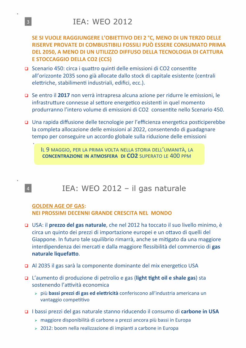
! SE#SI#VUOLE#RAGGIUNGERE#L’OBIETTIVO#DEI#2#°C,#MENO#DI#UN#TERZO#DELLE#RISERVE#PROVATE#DI#COMBUSTIBILI#FOSSILI#PUÒ#ESSERE#CONSUMATO#PRIMA#DEL#2050,#A#MENO#DI#UN#UTILIZZO#DIFFUSO#DELLA#TECNOLOGIA#DI#CATTURA#E#STOCCAGGIO#DELLA#CO2#(CCS)+
! Scenario+450:+circa+i+quaCro+quinD+delle+emissioni+di+CO2+consenDte+all’orizzonte+2035+sono+già+allocate+dallo+stock+di+capitale+esistente+(centrali+eleCriche,+stabilimenD+industriali,+edifici,+ecc.).+
! Se+entro+il+2017+non+verrà+intrapresa+alcuna+azione+per+ridurre+le+emissioni,+le+infrastruCure+connesse+al+seCore+energeDco+esistenD+in+quel+momento+produrranno+l’intero+volume+di+emissioni+di+CO2++consenDte+nello+Scenario+450.+
! Una+rapida+diffusione+delle+tecnologie+per+l’efficienza+energeDca+posDciperebbe+la+completa+allocazione+delle+emissioni+al+2022,+consentendo+di+guadagnare+tempo+per+conseguire+un+accordo+globale+sulla+riduzione+delle+emissioni+
+++++++++++IL+9+MAGGIO,+PER+LA+PRIMA+VOLTA+NELLA+STORIA+DELL’UMANITÀ,+LA## ############CONCENTRAZIONE#IN#ATMOSFERA##DI#CO2#SUPERATO+LE+400+PPM+
IEA: WEO 2012 3+
" GOLDEN#AGE#OF#GAS: " NEI#PROSSIMI#DECENNI#GRANDE#CRESCITA#NEL##MONDO
! USA:+il+prezzo#del#gas#naturale,+che+nel+2012+ha+toccato+il+suo+livello+minimo,+è+circa+un+quinto+dei+prezzi+di+importazione+europei+e+un+oCavo+di+quelli+del+Giappone.+In+futuro+tale+squilibrio+rimarrà,+anche+se+miDgato+da+una+maggiore+interdipendenza+dei+mercaD+e+dalla+maggiore+flessibilità+del+commercio+di+gas#naturale#liquefaRo.+
! Al+2035+il+gas+sarà+la+componente+dominante+del+mix+energeDco+USA+
! L’aumento+di+produzione+di+petrolio+e+gas+(light#Tght#oil#e#shale#gas)+sta+sostenendo+l’aavità+economica+# più+bassi#prezzi#di#gas#ed#eleRricità#conferiscono+all’industria+americana+un+
vantaggio+compeDDvo+
! I+bassi+prezzi+del+gas+naturale+stanno+riducendo+il+consumo+di+carbone#in#USA # maggiore+disponibilità+di+carbone+a+prezzi+ancora+più+bassi+in+Europa++
# 2012:+boom+nella+realizzazione+di+impianD+a+carbone+in+Europa+
IEA: WEO 2012 – il gas naturale 4+
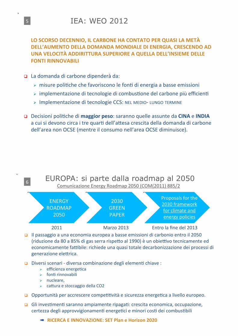
! LO#SCORSO#DECENNIO,#IL#CARBONE#HA#CONTATO#PER#QUASI#LA#METÀ#DELL’AUMENTO#DELLA#DOMANDA#MONDIALE#DI#ENERGIA,#CRESCENDO#AD#UNA#VELOCITÀ#ADDIRITTURA#SUPERIORE#A#QUELLA#DELL’INSIEME#DELLE#FONTI#RINNOVABILI+
! La+domanda+di+carbone+dipenderà+da:+
# misure+poliDche+che+favoriscono+le+fonD+di+energia+a+basse+emissioni+
# implementazione+di+tecnologie+di+combusDone+del+carbone+più+efficienD+
# Implementazione+di+tecnologie+CCS:+NEL+MEDIOc+LUNGO+TERMINE+
! Decisioni+poliDche+di+maggior#peso:+saranno+quelle+assunte+da+CINA+e+INDIA+++a+cui+si+devono+circa+i+tre+quarD+dell’aCesa+crescita+della+domanda+di+carbone+dell’area+non+OCSE+(mentre+il+consumo+nell’area+OCSE+diminuisce).++
IEA: WEO 2012 5+
EUROPA: si parte dalla roadmap al 2050 ++++++++++Comunicazione+Energy+Roadmap+2050+(COM(2011)+885/2+
! Il+passaggio+a+una+economia+europea+a+basse+emissioni+di+carbonio+entro+il+2050+(riduzione+da+80+a+85%+di+gas+serra+rispeCo+al+1990)+è+un+obieavo+tecnicamente+ed+economicamente+faabile:+richiede+una+quasi+totale+decarbonizzazione+dei+processi+di+generazione+eleCrica.+
! Diversi+scenari+c+diversa+combinazione+degli+elemenD+chiave+:++# efficienza+energeDca+# fonD+rinnovabili+# nucleare,+# caCura+e+stoccaggio+della+CO2+
! Opportunità+per+accrescere+compeDDvità+e+sicurezza+energeDca+a+livello+europeo.+
! Gli+invesDmenD+saranno+ampiamente+ripagaD:+crescita+economica,+occupazione,+certezza+degli+approvvigionamenD+energeDci+e+minori+cosD+dei+combusDbili+
� RICERCA#E#INNOVAZIONE:#SET#Plan#e#Horizon#2020#
ENERGY+ROADMAP+
2050+
2030+GREEN+PAPER+
Proposals+for+the+2030+framework+for+climate+and+energy+policies+
2011+ Marzo+2013+ Entro+la+fine+del+2013+
6+
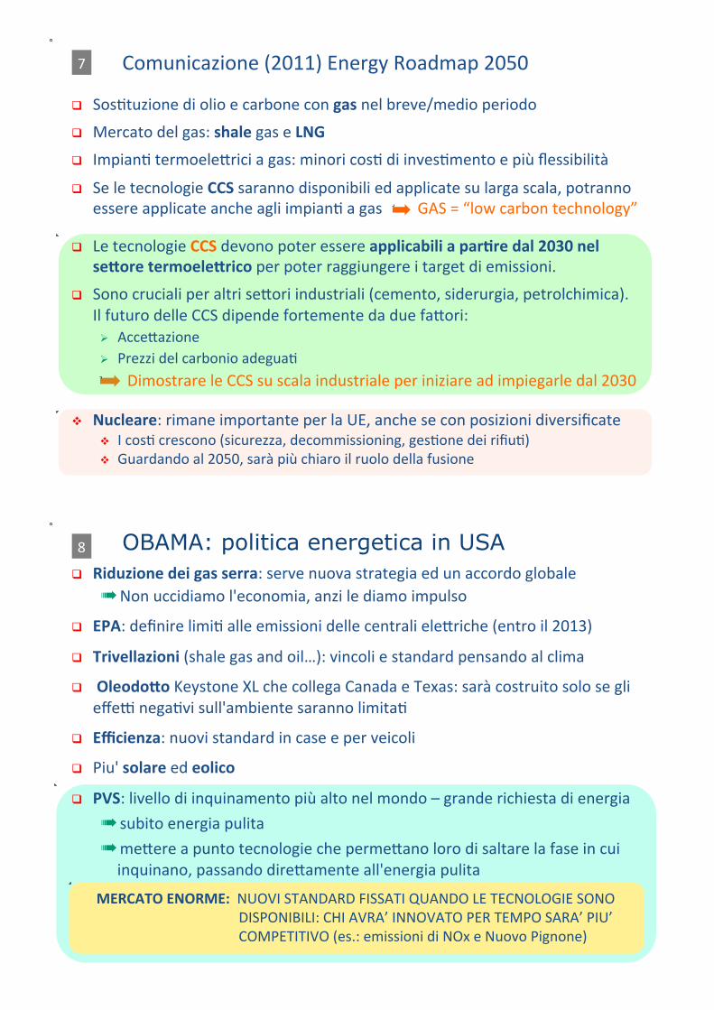
! SosDtuzione+di+olio+e+carbone+con+gas+nel+breve/medio+periodo+
! Mercato+del+gas:+shale+gas+e+LNG ! ImpianD+termoeleCrici+a+gas:+minori+cosD+di+invesDmento+e+più+flessibilità+
! Se+le+tecnologie+CCS+saranno+disponibili+ed+applicate+su+larga+scala,+potranno+essere+applicate+anche+agli+impianD+a+gas+++++++++GAS+=+“low+carbon+technology”+
! Le+tecnologie+CCS+devono+poter+essere+applicabili+a#parTre#dal#2030#nel#seRore#termoeleRrico#per+poter+raggiungere+i+target+di+emissioni.+
! Sono+cruciali+per+altri+seCori+industriali+(cemento,+siderurgia,+petrolchimica).++Il+futuro+delle+CCS+dipende+fortemente+da+due+faCori:+# AcceCazione++# Prezzi+del+carbonio+adeguaD+
+ +Dimostrare+le+CCS+su+scala+industriale+per+iniziare+ad+impiegarle+dal+2030+
" Nucleare:+rimane+importante+per+la+UE,+anche+se+con+posizioni+diversificate+" I+cosD+crescono+(sicurezza,+decommissioning,+gesDone+dei+rifiuD)+" Guardando+al+2050,+sarà+più+chiaro+il+ruolo+della+fusione+
Comunicazione+(2011)+Energy+Roadmap+2050+
7+
! Riduzione#dei#gas#serra:+serve+nuova+strategia+ed+un+accordo+globale+� Non+uccidiamo+l'economia,+anzi+le+diamo+impulso+
! EPA:+definire+limiD+alle+emissioni+delle+centrali+eleCriche+(entro+il+2013)+
! Trivellazioni+(shale+gas+and+oil…):+vincoli+e+standard+pensando+al+clima+
! +OleodoRo+Keystone+XL+che+collega+Canada+e+Texas:+sarà+costruito+solo+se+gli+effea+negaDvi+sull'ambiente+saranno+limitaD++
! Efficienza:+nuovi+standard+in+case+e+per+veicoli+
! Piu'+solare+ed+eolico
! PVS:+livello+di+inquinamento+più+alto+nel+mondo+–+grande+richiesta+di+energia++
� subito+energia+pulita+� meCere+a+punto+tecnologie+che+permeCano+loro+di+saltare+la+fase+in+cui+inquinano,+passando+direCamente+all'energia+pulita+
#######MERCATO#ENORME:#+NUOVI+STANDARD+FISSATI+QUANDO+LE+TECNOLOGIE+SONO++++++++++++++++++++++++++++++++++++++++++++++++DISPONIBILI:+CHI+AVRA’+INNOVATO+PER+TEMPO+SARA’+PIU’+++++++++++++++++++++++++++++++++++++++++++++++++COMPETITIVO+(es.:+emissioni+di+NOx+e+Nuovo+Pignone)+
OBAMA: politica energetica in USA 8+
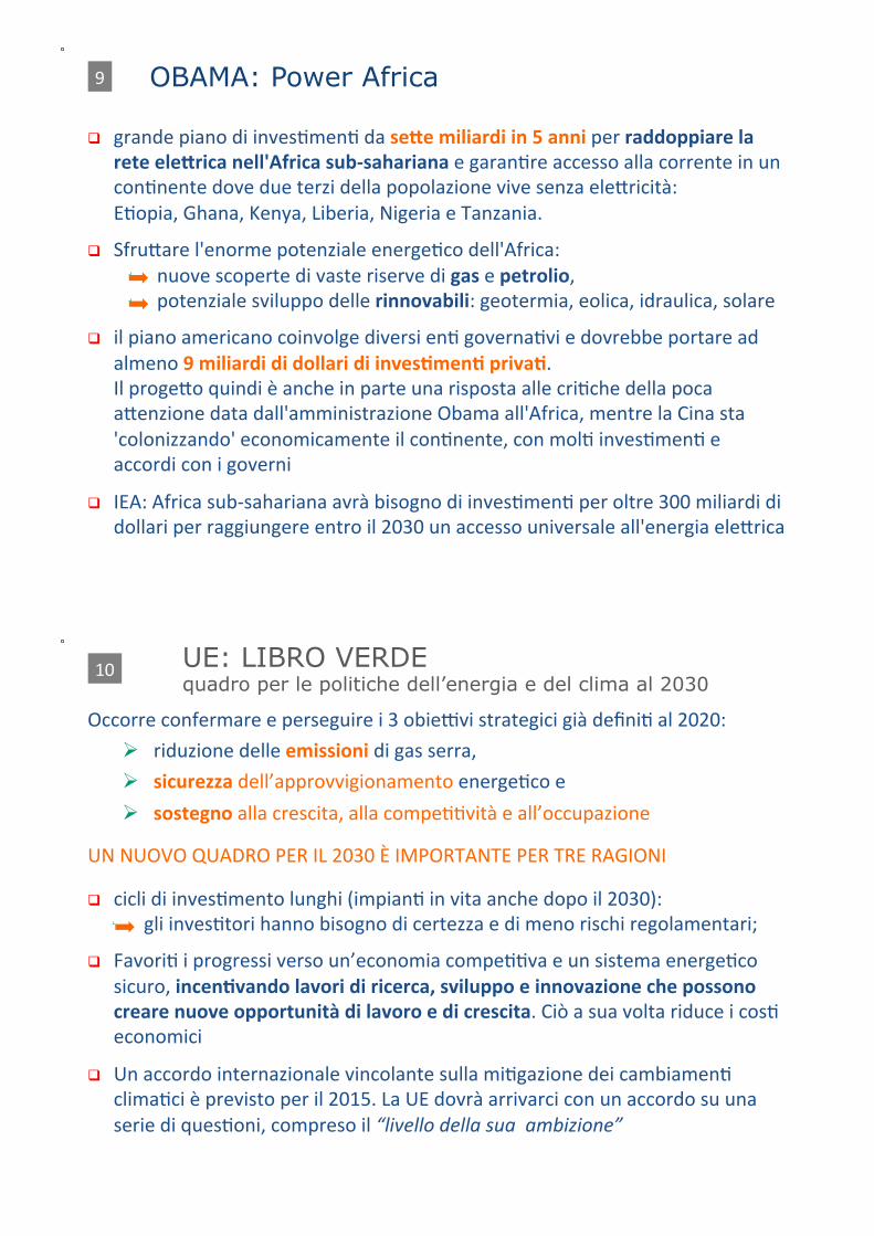
! grande+piano+di+invesDmenD+da+seRe#miliardi#in#5#anni+per+raddoppiare#la#rete#eleRrica#nell'Africa#sub`sahariana+e+garanDre+accesso+alla+corrente+in+un+conDnente+dove+due+terzi+della+popolazione+vive+senza+eleCricità:++
! EDopia,+Ghana,+Kenya,+Liberia,+Nigeria+e+Tanzania.+
! SfruCare+l'enorme+potenziale+energeDco+dell'Africa:+nuove+scoperte+di+vaste+riserve+di+gas+e+petrolio,+potenziale+sviluppo+delle+rinnovabili:+geotermia,+eolica,+idraulica,+solare+
! il+piano+americano+coinvolge+diversi+enD+governaDvi+e+dovrebbe+portare+ad+almeno+9#miliardi#di#dollari#di#invesTmenT#privaT.+
! Il+progeCo+quindi+è+anche+in+parte+una+risposta+alle+criDche+della+poca+aCenzione+data+dall'amministrazione+Obama+all'Africa,+mentre+la+Cina+sta+'colonizzando'+economicamente+il+conDnente,+con+molD+invesDmenD+e+accordi+con+i+governi+
! IEA:+Africa+subcsahariana+avrà+bisogno+di+invesDmenD+per+oltre+300+miliardi+di+dollari+per+raggiungere+entro+il+2030+un+accesso+universale+all'energia+eleCrica+
OBAMA: Power Africa 9+
Occorre+confermare+e+perseguire+i+3+obieavi+strategici+già+definiD+al+2020:++
# ++riduzione+delle+emissioni+di+gas+serra,++# ++sicurezza#dell’approvvigionamento#energeDco+e++# ##sostegno#alla+crescita,+alla+compeDDvità+e+all’occupazione+
UN+NUOVO+QUADRO+PER+IL+2030+È+IMPORTANTE+PER+TRE+RAGIONI+
! cicli+di+invesDmento+lunghi+(impianD+in+vita+anche+dopo+il+2030):+! gli+invesDtori+hanno+bisogno+di+certezza+e+di+meno+rischi+regolamentari;++
! FavoriD+i+progressi+verso+un’economia+compeDDva+e+un+sistema+energeDco+sicuro,+incenTvando#lavori#di#ricerca,#sviluppo#e#innovazione#che#possono#creare#nuove#opportunità#di#lavoro#e#di#crescita.+Ciò+a+sua+volta+riduce+i+cosD+economici+
! Un+accordo+internazionale+vincolante+sulla+miDgazione+dei+cambiamenD+climaDci+è+previsto+per+il+2015.+La+UE+dovrà+arrivarci+con+un+accordo+su+una+serie+di+quesDoni,+compreso+il+“livello'della'sua''ambizione”
+
UE: LIBRO VERDE quadro per le politiche dell’energia e del clima al 2030
10+
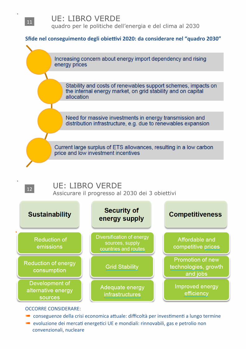
Sfide#nel#conseguimento#degli#obiecvi#2020:#da#considerare#nel#“quadro#2030”
UE: LIBRO VERDE quadro per le politiche dell’energia e del clima al 2030
11+
OCCORRE+CONSIDERARE:+� conseguenze+della+crisi+economica+aCuale:+difficoltà+per+invesDmenD+a+lungo+termine+� evoluzione+dei+mercaD+energeDci+UE+e+mondiali:+rinnovabili,+gas+e+petrolio+non+
convenzionali,+nucleare+
UE: LIBRO VERDE Assicurare il progresso al 2030 dei 3 obiettivi
12+
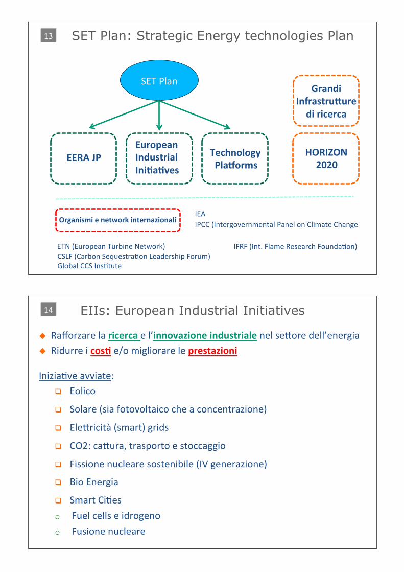
SET Plan: Strategic Energy technologies Plan
SET+Plan+
EERA#JP European#Industrial#IniTaTves
Technology### ##Plahorms
Grandi#InfrastruRure#di#ricerca
HORIZON 2020
Organismi#e#network#internazionali IEA+
IFRF+(Int.+Flame+Research+FoundaDon)+ETN+(European+Turbine+Network)+CSLF+(Carbon+SequestraDon+Leadership+Forum)+Global+CCS+InsDtute+
IPCC+(Intergovernmental+Panel+on+Climate+Change+
13+
IniziaDve+avviate:+! ++Eolico+
! ++Solare+(sia+fotovoltaico+che+a+concentrazione)+
! ++EleCricità+(smart)+grids+
! ++CO2:+caCura,+trasporto+e+stoccaggio+
! ++Fissione+nucleare+sostenibile+(IV+generazione)+
! ++Bio+Energia+
! ++Smart+CiDes+
o ++Fuel+cells+e+idrogeno+
o ++Fusione+nucleare+
$ Rafforzare+la+ricerca+e+l’innovazione#industriale#nel+seCore+dell’energia+$ Ridurre+i+cosT+e/o+migliorare+le+prestazioni
EIIs: European Industrial Initiatives 14+
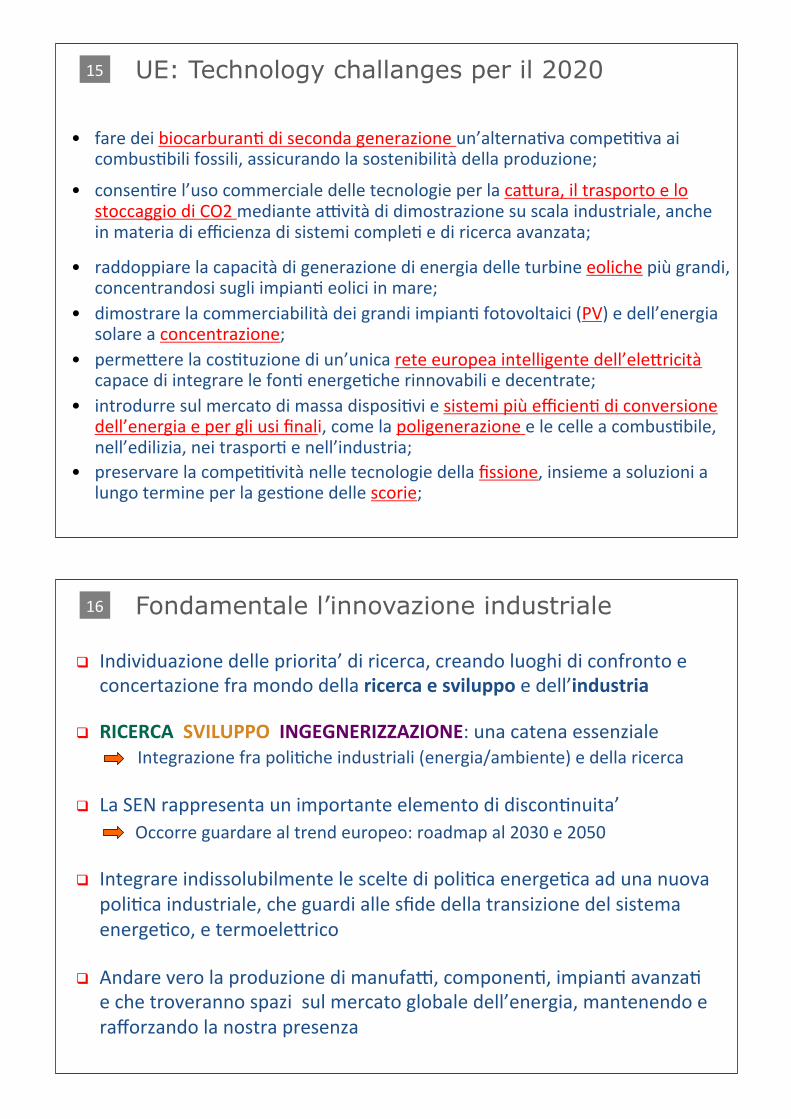
UE: Technology challanges per il 2020
• fare+dei+biocarburanD+di+seconda+generazione+un’alternaDva+compeDDva+ai+combusDbili+fossili,+assicurando+la+sostenibilità+della+produzione;+
• consenDre+l’uso+commerciale+delle+tecnologie+per+la+caCura,+il+trasporto+e+lo+stoccaggio+di+CO2+mediante+aavità+di+dimostrazione+su+scala+industriale,+anche+in+materia+di+efficienza+di+sistemi+compleD+e+di+ricerca+avanzata;+
• raddoppiare+la+capacità+di+generazione+di+energia+delle+turbine+eoliche+più+grandi,+concentrandosi+sugli+impianD+eolici+in+mare;+
• dimostrare+la+commerciabilità+dei+grandi+impianD+fotovoltaici+(PV)+e+dell’energia+solare+a+concentrazione;+
• permeCere+la+cosDtuzione+di+un’unica+rete+europea+intelligente+dell’eleCricità+capace+di+integrare+le+fonD+energeDche+rinnovabili+e+decentrate;+
• introdurre+sul+mercato+di+massa+disposiDvi+e+sistemi+più+efficienD+di+conversione+dell’energia+e+per+gli+usi+finali,+come+la+poligenerazione+e+le+celle+a+combusDbile,+nell’edilizia,+nei+trasporD+e+nell’industria;+
• preservare+la+compeDDvità+nelle+tecnologie+della+fissione,+insieme+a+soluzioni+a+lungo+termine+per+la+gesDone+delle+scorie;++
15+
! Individuazione+delle+priorita’+di+ricerca,+creando+luoghi+di+confronto+e+concertazione+fra+mondo+della+ricerca#e#sviluppo#e+dell’industria
! RICERCA##SVILUPPO##INGEGNERIZZAZIONE:+una+catena+essenziale+++++++++++++++++++Integrazione+fra+poliDche+industriali+(energia/ambiente)+e+della+ricerca+
! La+SEN+rappresenta+un+importante+elemento+di+disconDnuita’++++++++Occorre+guardare+al+trend+europeo:+roadmap+al+2030+e+2050+
! Integrare+indissolubilmente+le+scelte+di+poliDca+energeDca+ad+una+nuova+poliDca+industriale,+che+guardi+alle+sfide+della+transizione+del+sistema+energeDco,+e+termoeleCrico+
! Andare+vero+la+produzione+di+manufaa,+componenD,+impianD+avanzaD+e+che+troveranno+spazi++sul+mercato+globale+dell’energia,+mantenendo+e+rafforzando+la+nostra+presenza+
Fondamentale l’innovazione industriale 16+
! E’+in+corso+una+colossale+compeDzione+sulle+tecnologie+energeDche,+che+condizionerà+il+sistema+industriale+dei+principali+Paesi+
! Guardare+i+trend+internazionali+considerando+punD+di+forza+e+debolezza+del+nostro+sistema+industriale,+individuando+i+seCori+strategici,+e+dotandoci+di+“strumenD”+++
+++Domanda1+! possiamo+permeCerci+che+–+dopo+la+decrescita+(infelice)+di+molD+seCori+industriali+c+chimico,+automobilisDco,+siderurgico,+ecc..+c+anche+quello+dell’impianTsTca#energeTca#segua+la+stessa+fine?+No!+
! Una+tale+concentrazione+di+conoscenze,+capacità+di+progeCazione+e+ingegneria,+e+capacità+di+esercizio+accumulate+in+decenni+si+può+perdere+in+pochissimo+tempo,+se+si+perde+il+treno+dell’innovazione+(che+passa+ora)+
++++Domanda2+! Esistono+priorità+comuni+a+seCori+andaD+in+crisi+e+da+sostenere+e+rilanciare?++! C’e’+una+priorita’+comune+al+seCore+della+produzione+di+eleRricita’+e+a+quelli+
siderurgico,+petrolchimico,+del+cemento:+la+limitazione+delle+emissioni+di+CO2+
In Italia
cc+
cc
17+
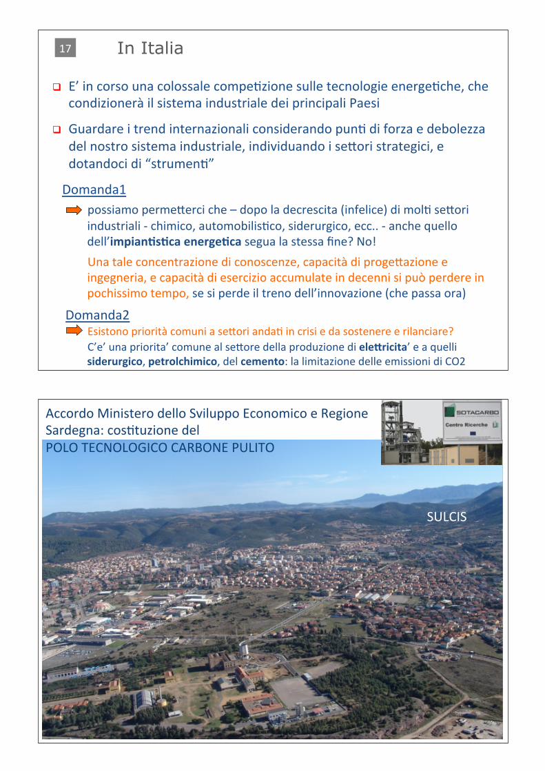
SULCIS+
Accordo+Ministero+dello+Sviluppo+Economico+e+Regione+Sardegna:+cosDtuzione+del+POLO+TECNOLOGICO+CARBONE+PULITO+
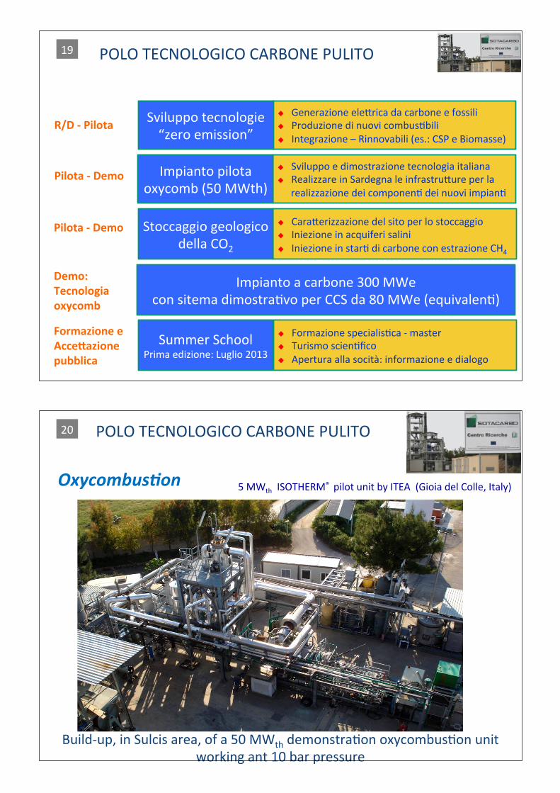
POLO+TECNOLOGICO+CARBONE+PULITO+
$ Sviluppo+e+dimostrazione+tecnologia+italiana+$ Realizzare+in+Sardegna+le+infrastruCure+per+la+
realizzazione+dei+componenD+dei+nuovi+impianD+
Impianto+pilota+oxycomb+(50+MWth)+
$ CaraCerizzazione+del+sito+per+lo+stoccaggio+$ Iniezione+in+acquiferi+salini+$ Iniezione+in+starD+di+carbone+con+estrazione+CH4+
Stoccaggio+geologico+della+CO2+
Impianto+a+carbone+300+MWe+con+sitema+dimostraDvo+per+CCS+da+80+MWe+(equivalenD)+
R/D#`#Pilota
Pilota#`#Demo
Pilota#`#Demo
Demo: Tecnologia oxycomb
Summer+School+Prima+edizione:+Luglio+2013+
Formazione#e AcceRazione pubblica
$ Generazione+eleCrica+da+carbone+e+fossili+$ Produzione+di+nuovi+combusDbili+$ Integrazione+–+Rinnovabili+(es.:+CSP+e+Biomasse)+
Sviluppo+tecnologie+“zero+emission”+
$ Formazione+specialisDca+c+master+$ Turismo+scienDfico+$ Apertura+alla+socità:+informazione+e+dialogo+
19+
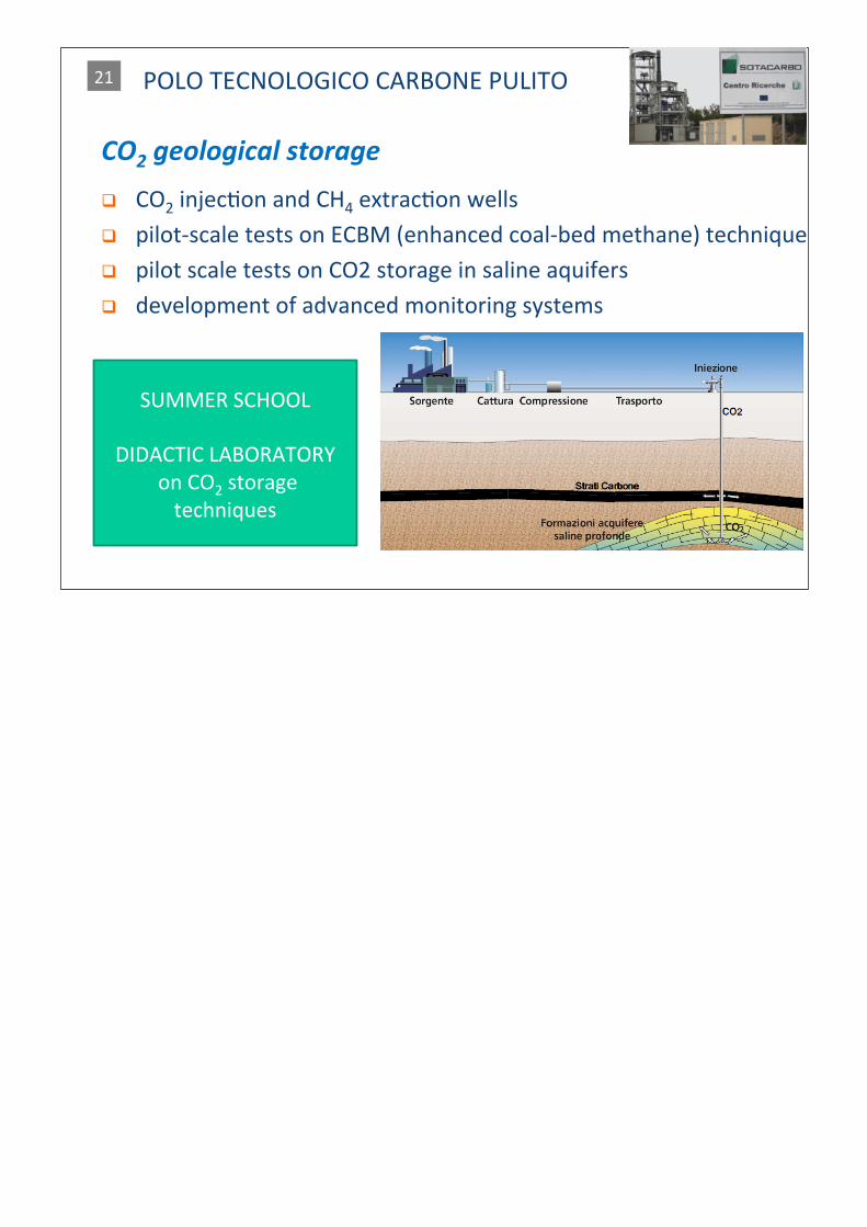
Oxycombus*on 5+MWth++ISOTHERM®++pilot+unit+by+ITEA++(Gioia+del+Colle,+Italy)
Buildcup,+in+Sulcis+area,+of+a+50+MWth+demonstraDon+oxycombusDon+unit+working+ant+10+bar+pressure+
POLO+TECNOLOGICO+CARBONE+PULITO+20+
CO2/geological/storage ! CO2+injecDon+and+CH4+extracDon+wells+
! pilotcscale+tests+on+ECBM+(enhanced+coalcbed+methane)+technique+
! pilot+scale+tests+on+CO2+storage+in+saline+aquifers+
! development+of+advanced+monitoring+systems+
SUMMER+SCHOOL++
DIDACTIC+LABORATORY++on+CO2+storage+techniques+
POLO+TECNOLOGICO+CARBONE+PULITO+21+

32
Allegato 2 - Current status of Italian Energy Strategy, with focus on natural gas, coal and CCS
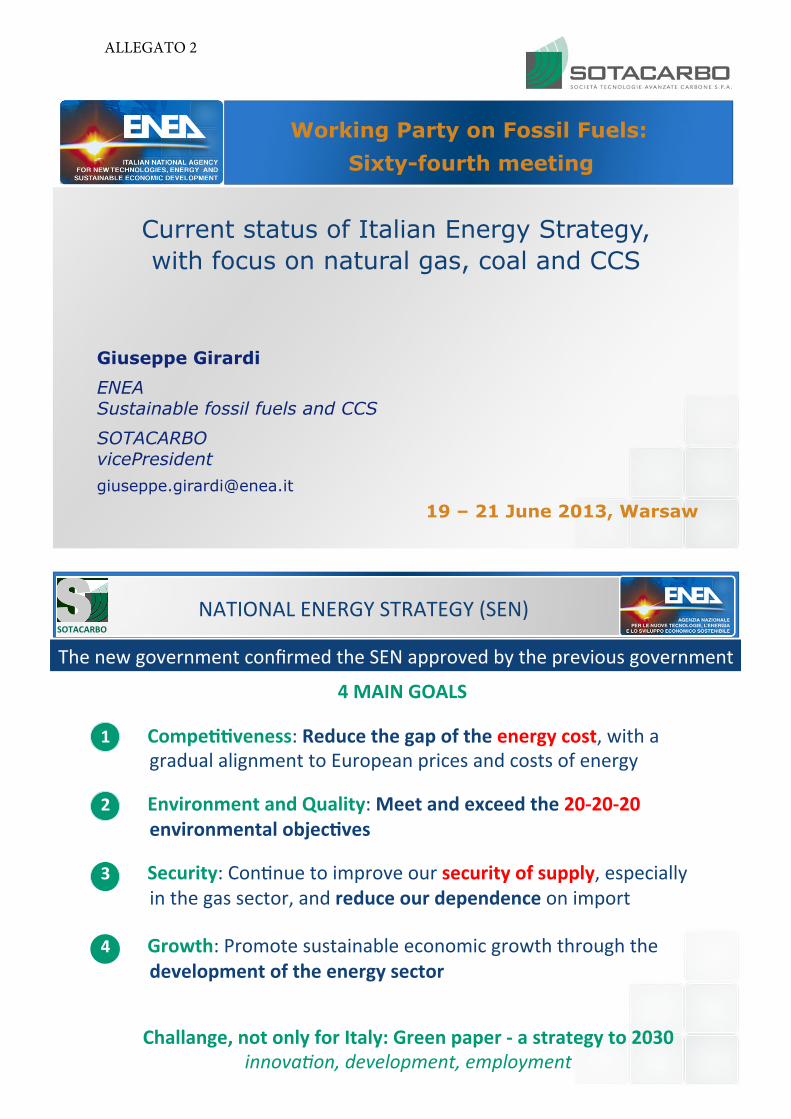
Current status of Italian Energy Strategy, with focus on natural gas, coal and CCS
Giuseppe Girardi ENEA Sustainable fossil fuels and CCS
SOTACARBO vicePresident [email protected]
19 – 21 June 2013, Warsaw
Working Party on Fossil Fuels: !
!Sixty-fourth meeting
NATIONAL!ENERGY!STRATEGY!(SEN)
1 Compe''veness:!Reduce/the/gap/of/the/energy/cost,!with!a!gradual!alignment!to!European!prices!and!costs!of!energy!
2 Environment/and/Quality:!Meet/and/exceed/the/20?20?20/
environmental/objec'ves!!
3 Security:!ConEnue!to!improve!our!security/of/supply,!especially!in!the!gas!sector,!and!reduce/our/dependence/on!import!
4 Growth:!Promote!sustainable!economic!growth!through!the!development/of/the/energy/sector
4/MAIN/GOALS
SOTACARBO
The!new!government!confirmed!the!SEN!approved!by!the!previous!government!
Challange,/not/only/for/Italy:/Green/paper/?/a/strategy/to/2030
innova'on,)development,)employment
ALLEGATO 2
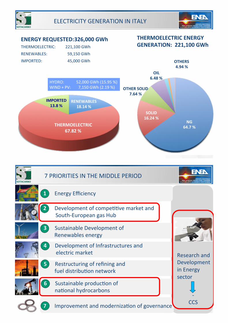
NG
64.7/%
SOLID
16.24/%
OTHER/SOLID
7.64/%
OIL
6.48/%
OTHERS
4.94/%
ENERGY/REQUESTED: 326,000/GWh
THERMOELECTRIC:! !221,100!GWh!RENEWABLES:! ! !!!59,150!GWh!IMPORTED:! ! ! !!!45,000!GWh!
NG!64.7%!
SOLID!16.24%!
THERMOELECTRIC
67.82/%
RENEWABLES
18.14/%
IMPORTED
13.8/%
HYDRO:! ! !52,000!GWh!(15.95!%)!WIND!+!PV: !!!7,150!GWh!(2.19!%)!
THERMOELECTRIC/ENERGY
GENERATION://221,100/GWh
ELECTRICITY!GENERATION!IN!ITALY!SOTACARBO
7!PRIORITIES!IN!THE!MIDDLE!PERIOD
Research!and!Development!in!Energy!sector!
1//////Energy!Efficiency!
2//////Development!of!compeEEve!market!and!!!!!!!!!!South]European!gas!Hub!
3//////Sustainable!Development!of!!!!!!!!!Renewables!energy!
4!!!!!!Development!of!Infrastructures!and!!!!!!!!!!electric!market!
5!!!!!!Restructuring!of!refining!and!!!!!!!!!fuel!distribuEon!network!
6/!!!!!Sustainable!producEon!of!!!!!!!!!naEonal!hydrocarbons!
7!!!!!!Improvement!and!modernizaEon!of!governance!
SOTACARBO
]!CCS!
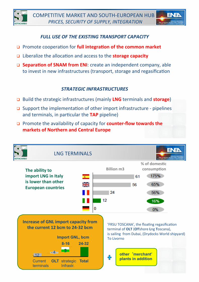
FULL$USE$OF$THE$EXISTING$TRANSPORT$CAPACITY
! Promote!cooperaEon!for!full/integra'on/of/the/common/market
! Liberalize!the!allocaEon!and!access!to!the!storage/capacity
! Separa'on/of/SNAM/from/ENI:!create!an!independent!company,!able!to!invest!in!new!infrastructures!(transport,!storage!and!regasificaEon!
!
STRATEGIC$INFRASTRUCTURES
! Build!the!strategic!infrastructures!(mainly!LNG!terminals!and!storage)!
! Support!the!implementaEon!of!other!import!infrastructure!]!pipelines!and!terminals,!in!parEcular!the!TAP!pipeline)!
! Promote!the!availability!of!capacity!for!counter?flow/towards/the/markets/of/Northern/and/Central/Europe
SOTACARBO
COMPETITIVE!MARKET!AND!SOUTH]EUROPEAN!HUB!PRICES,)SECURITY)OF)SUPPLY,)INTEGRATION
LNG!TERMINALS!
///////////////////////////////////%/of/domes'c/
Billion/m3/ /////////////consump'on
SOTACARBO
The/ability/to/
import/LNG/in/Italy/
is/lower/than/other/
European/countries
Increase/of/GNL/import/capacity/from/
the/current/12/bcm/to/24?32/bcm!
Current OLT terminals
strategic Total Infrastr.
"4 8
Import GNL, bcm !8-16 24-32
"12 other�merchant’ plants in addition
’FRSU!TOSCANA',!the!floaEng!regasificaEon!!terminal!of!OLT!(Offshore!Lng!Toscana),!is!sailing!!from!Dubai,!(Drydocks!World!shipyard)!To!Livorno!
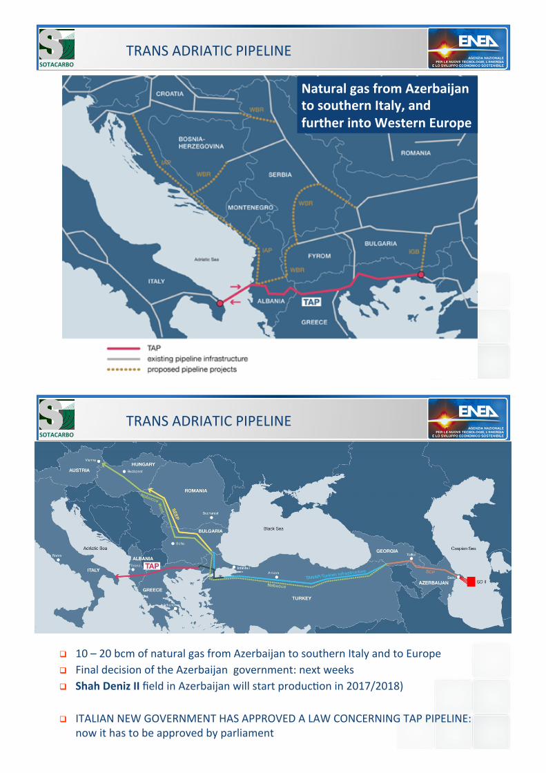
TRANS!ADRIATIC!PIPELINE
Natural/gas/from/Azerbaijan/
to/southern/Italy,/and/
further/into/Western/Europe/
SOTACARBO
TRANS!ADRIATIC!PIPELINE SOTACARBO
! 10!–!20!bcm!of!natural!gas!from!Azerbaijan!to!southern!Italy!and!to!Europe!! Final!decision!of!the!Azerbaijan!!government:!next!weeks!! Shah/Deniz/II/field!in!Azerbaijan!will!start!producEon!in!2017/2018)!
! ITALIAN!NEW!GOVERNMENT!HAS!APPROVED!A!LAW!CONCERNING!TAP!PIPELINE:!now!it!has!to!be!approved!by!parliament!
SAFETY!! Strengthen!safety!measures!in!plants!and!infrastructures!operaEon!! No!projects!–!in!parEcular!those!!on!shale!gas!–!in!prized!and!protected!areas!! Shale!gas:!it!isn’t!a!current!opEon!
AUTHORIZATION!PROCEDURES!–!Reduce!Bureaucracy!! New!procedures!for!authorizaEon,!and!full!license!for!exploraEon!and!producEon!! Public!consultaEon!in!order!to!achieve!acceptance!and!reduce!Eme!! Compression/sta'on/at/SULMONA/for!adriaEc!pipeline!(but!some!public!!opposiEon)!
" Ministry!of!development!is!approving!procedures!for!public!consultaEon,!as!for!CO2!storage!(EU!derecEve!already!adopted)!
OFF!SHORE!–!increase!producEon,!mainly!natural!gas!! Gas/and/oil/well/at/OMBRINA!(but!some!public!opposiEon)!
DEVELOPMENT!OF!REGIONS!AND!INDUSTRIAL!POLES!! Support!the!strengthening!of!technological/industrial!!poles!in!Emilia!Romagna,!
Lombardia,!Abruzzo,!Basilicata,!Sicily!
DEVELOPMENT!OF!NATIONAL!HYDROCARBONS!Increase!producEon!of!hydrocarbon!and!support!the!industry!!
SOTACARBO
RESEARCH!
! ! ! !PRIORITIES!
! InnovaEve!renewable!technologies,!as!concentraEng!solar!power!and!second]generaEon!biofuels!
! Intelligent!networks!(smart!grids,!also!to!facilitate!distributed!generaEon),!and!storage!systems,!also!with!a!view!to!sustainable!mobility!
! Materials!and!energy!efficiency!soluEons!and!their!technology!transfer!
! Development!of!projects!on!CCS,!in!accordance!with!European!strategy!and!programmes,!aimed!at!accelerate!innovaEon!in!power!plants!as!opportunity!for!Industry!to!compete!on!the!internaEonal!market!" Medium!Eme!
SOTACARBO
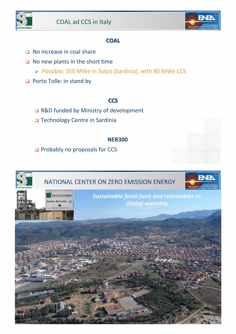
COAL!ad!CCS!in!Italy!
COAL
! No!increase!in!coal!share!! No!new!plants!in!the!short!Eme!
" Possible:!350!MWe!in!Sulcis!(Sardinia),!with!80!MWe!CCS!! Porto!Tolle:!in!stand!by!!
CCS
! R&D!funded!by!Ministry!of!development!! Technology!Centre!in!Sardinia!
!NER300
! Probably!no!proposals!for!CCS!
SOTACARBO
NATIONAL!CENTER!ON!ZERO!EMISSION!ENERGY SOTACARBO
Sustainable$fossil$fuels$and$renewables$vs Global$warming
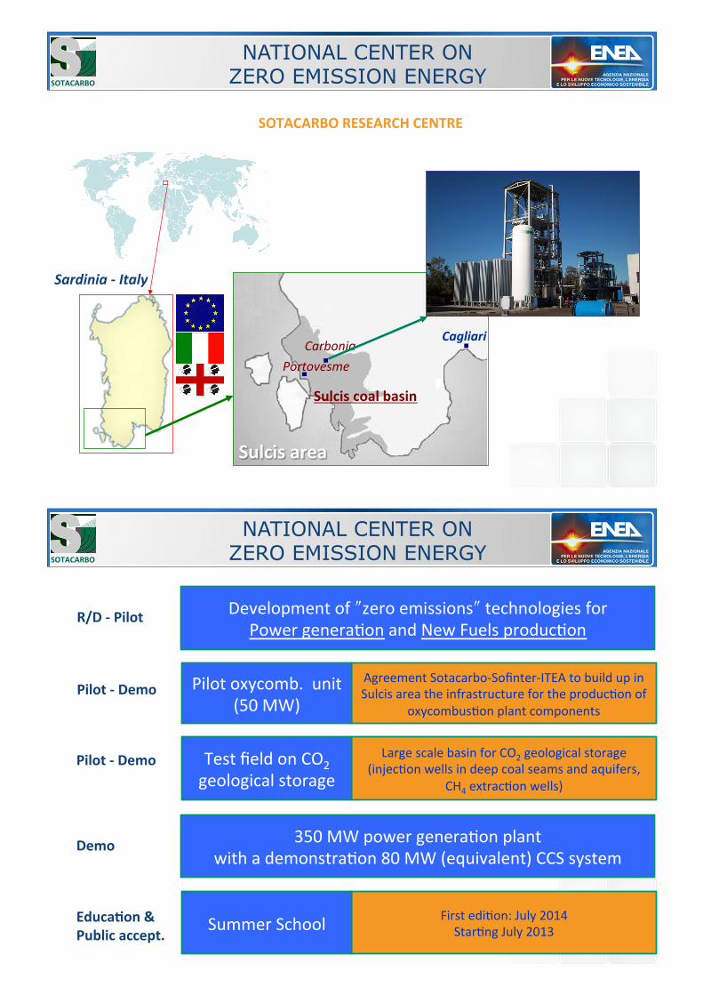
NATIONAL CENTER ON ZERO EMISSION ENERGY SOTACARBO
Carbonia Cagliari
Portovesme
Sulcis/coal/basin
Sardinia$E$Italy
Sulcis/area
SOTACARBO/RESEARCH/CENTRE
Agreement!Sotacarbo]Sofinter]ITEA!to!build!up!in!Sulcis!area!the!infrastructure!for!the!producEon!of!
oxycombusEon!plant!components!
Pilot!oxycomb.!!unit!(50!MW)!
Large!scale!basin!for!CO2!geological!storage!(injecEon!wells!in!deep!coal!seams!and!aquifers,!
CH4!extracEon!wells)!
Test!field!on!CO2!geological!storage!
Development!of!!zero!emissions!!technologies!for!Power!generaEon!and!New!Fuels!producEon!
350!MW!power!generaEon!plant!with!a!demonstraEon!80!MW!(equivalent)!CCS!system!
R/D/?/Pilot
Pilot/?/Demo
Pilot/?/Demo
Demo
NATIONAL CENTER ON ZERO EMISSION ENERGY SOTACARBO
First!ediEon:!July!2014!StarEng!July!2013!!Summer!School!Educa'on/&
Public/accept.
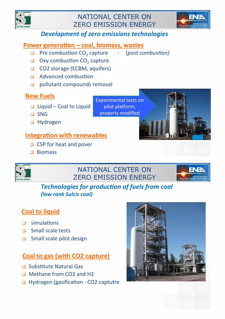
Development$of$zero$emissions$technologies
! Pre!combusEon!CO2!capture!!!!!!!]!!!!!(post)combus'on) ! Oxy!combusEon!CO2!capture!! CO2!storage!(ECBM,!aquifers)!! Advanced!combusEon!! pollutant!compounds!removal!
Experimental!tests!on!pilot!plaporm,!
properly!modified!
NATIONAL CENTER ON ZERO EMISSION ENERGY SOTACARBO
! Liquid!–!Coal!to!Liquid!! SNG!! Hydrogen!
New/Fuels
Integra'on/with/renewables
! CSP!for!heat!and!pover!! Biomass!
Power/genera'on/–/coal,/biomass,/wastes
Technologies$for$producLon$of$fuels$from$coal (low$rank$Sulcis$coal)
! simulaEons ! Small!scale!tests!! Small!scale!pilot!design!
NATIONAL CENTER ON ZERO EMISSION ENERGY SOTACARBO
! SubsEtute!Natural!Gas!! Methane!from!CO2!and!H2!! Hydrogen!(gasificaEon!]!CO2!captutre!
Coal/to/gas/(with/CO2/capture)
Coal/to/liquid
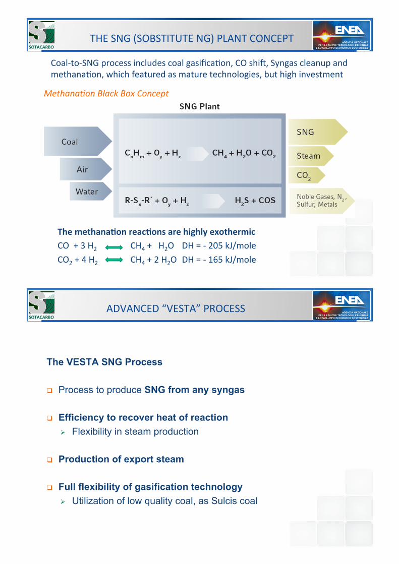
The/methana'on/reac'ons/are/highly/exothermic
CO!!+!3!H2! !!!!!!!!!!!!!CH4!+!!!H2O !DH!=!]!205!kJ/mole!CO2!+!4!H2! !!!!!!!!!!!!!CH4!+!2!H2O !DH!=!]!165!kJ/mole!
THE!SNG!(SOBSTITUTE!NG)!PLANT!CONCEPT!SOTACARBO
Coal]to]SNG!process!includes!coal!gasificaEon,!CO!shir,!Syngas!cleanup!and!methanaEon,!which!featured!as!mature!technologies,!but!high!investment!
Methana'on)Black)Box)Concept
The VESTA SNG Process
! Process to produce SNG from any syngas
! Efficiency to recover heat of reaction " Flexibility in steam production
! Production of export steam
! Full flexibility of gasification technology " Utilization of low quality coal, as Sulcis coal
ADVANCED!“VESTA”!PROCESS!SOTACARBO
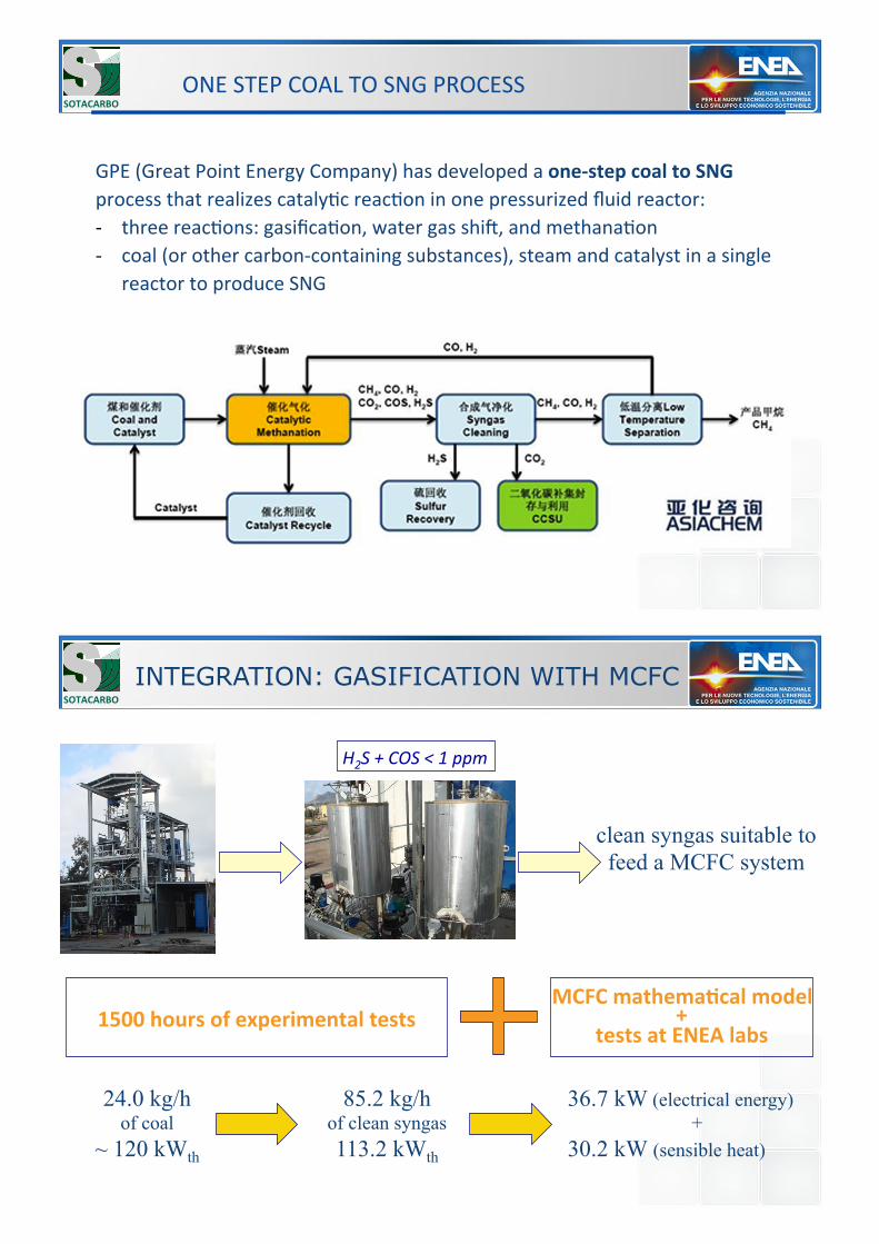
ONE!STEP!COAL!TO!SNG!PROCESS!SOTACARBO
GPE!(Great!Point!Energy!Company)!has!developed!a!one?step/coal/to/SNG/process!that!realizes!catalyEc!reacEon!in!one!pressurized!fluid!reactor:!] three!reacEons:!gasificaEon,!water!gas!shir,!and!methanaEon!] coal!(or!other!carbon]containing!substances),!steam!and!catalyst!in!a!single!
reactor!to!produce!SNG!!
clean syngas suitable to feed a MCFC system
H2S)+)COS)<)1)ppm
24.0 kg/h of coal
~ 120 kWth
85.2 kg/h of clean syngas 113.2 kWth
36.7 kW (electrical energy) +
30.2 kW (sensible heat)
1500/hours/of/experimental/tests MCFC/mathema'cal/model/
+ tests/at/ENEA/labs
INTEGRATION: GASIFICATION WITH MCFC SOTACARBO
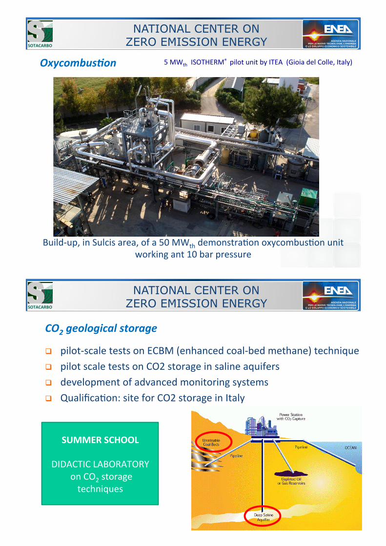
OxycombusLon 5!MWth!!ISOTHERM®!!pilot!unit!by!ITEA!!(Gioia!del!Colle,!Italy)
Build]up,!in!Sulcis!area,!of!a!50!MWth!demonstraEon!oxycombusEon!unit!working!ant!10!bar!pressure!
NATIONAL CENTER ON ZERO EMISSION ENERGY SOTACARBO
CO2$geological$storage
! pilot]scale!tests!on!ECBM!(enhanced!coal]bed!methane)!technique!! pilot!scale!tests!on!CO2!storage!in!saline!aquifers!! development!of!advanced!monitoring!systems!! QualificaEon:!site!for!CO2!storage!in!Italy!
SUMMER/SCHOOL
!DIDACTIC!LABORATORY!
!on!CO2!storage!techniques!
NATIONAL CENTER ON ZERO EMISSION ENERGY SOTACARBO
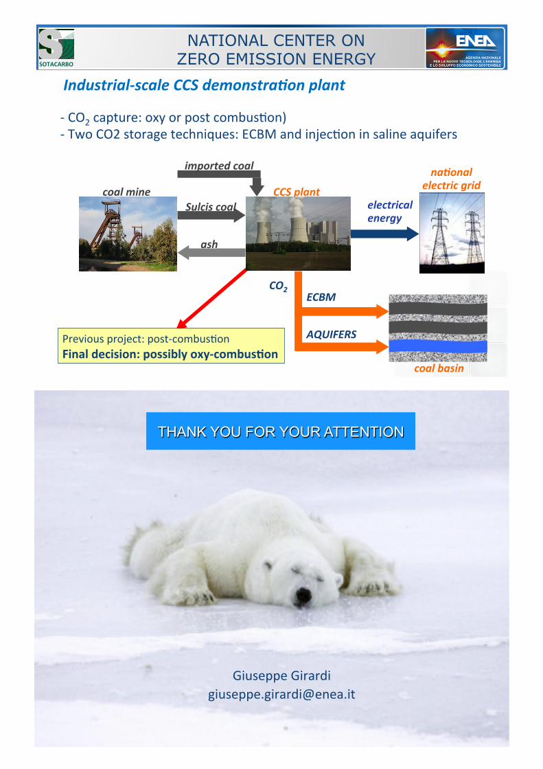
IndustrialEscale$CCS$demonstraLon$plant
Sulcis$coal electrical energy
ash
coal$mine CCS$plant
naLonal$electric$grid
imported$coal
CO2
coal$basin
!]!CO2!capture:!oxy!or!post!combusEon)!!]!Two!CO2!storage!techniques:!ECBM!and!injecEon!in!saline!aquifers!
NATIONAL CENTER ON ZERO EMISSION ENERGY SOTACARBO
ECBM
AQUIFERS Previous!project:!post]combusEon!Final/decision:/possibly/oxy?combus'on
XXXIV Meeting of the italian Section of the Combustion Institute
THANK YOU FOR YOUR ATTENTION
!

ACCORDO DI PROGRAMMA MSE-ENEA
45
Allegato 3 - Recommendations for research to support CCS deployment in Europe beyond 2020 – update on CO2 capture
Recommendations for research to support CCS deployment in Europe beyond 2020
Update on CO2 Capture
ALLEGATO 3
2
Contents 1 INTRODUCTION ........................................................................................................................................... 3
2 RECOMMENDATIONS FOR RESEARCH ON CO2 CAPTURE................................................................... 5
2.1 Technology structure and evaluation methodology ......................................................................... 5 2.1.1 Definition of timeframe ..................................................................................................................... 5 2.1.2 Capture routes and technology blocks ............................................................................................. 5 2.1.3 Definition of validation status ........................................................................................................... 7 2.1.4 Methodology for evaluating the importance of R&D topics .............................................................. 7
2.2 Post-combustion technologies.. ......................................................................................................... 8 2.2.1 CO2 capture in post-combustion applications .................................................................................. 8 2.2.2 CO2 enrichment in flue gas from gas turbines ............................................................................... 10 2.2.3 Overall process development and integration ................................................................................ 11
2.3 Oxy-fuel technologies.. ...................................................................................................................... 11 2.3.1 Oxygen production for oxy-fuel applications .................................................................................. 11 2.3.2 Oxy-fuel boilers .............................................................................................................................. 12 2.3.3 Oxy-fuel gas turbine ....................................................................................................................... 13 2.3.4 Flue gas recycling and O2 mixing ................................................................................................... 14 2.3.5 Flue gas treatment and cooling ...................................................................................................... 15 2.3.6 CO2 purification and compression .................................................................................................. 15 2.3.7 Integrated components (including CLC) ......................................................................................... 16 2.3.8 Overall process development and integration ................................................................................ 17
2.4 Pre-combustion technologies.. ......................................................................................................... 18 2.4.1 Oxygen production for pre-combustion applications ...................................................................... 18 2.4.2 Gasification/reforming .................................................................................................................... 19 2.4.3 Water-gas shift ............................................................................................................................... 20 2.4.4 CO2 capture in pre-combustion applications .................................................................................. 20 2.4.5 H2 gas turbine ................................................................................................................................ 21 2.4.6 Integrated components .................................................................................................................. 22 2.4.7 Overall process development and integration ................................................................................ 23
2.5 Technologies and research areas for improved CO2 capture performance ................................. 24 2.5.1 Advanced steam cycle technology ................................................................................................. 24 2.5.2 Other technology development ...................................................................................................... 25 2.5.3 System studies ............................................................................................................................... 26
2.6 CO2 capture from power plants .......................................................................................................... 27 2.6.1 General recommendations .............................................................................................................. 27 2.6.2 Post-combustion capture technologies ........................................................................................... 28 2.6.3 Oxy-fuel technologies ...................................................................................................................... 29 2.6.4 Pre-combustion technologies .......................................................................................................... 29
ANNEX: Bio-CCS and CCS in industries beyond power ........................................................................... 31
This document has been prepared on behalf of the Advisory Council of the European Technology Platform for Zero Emission Fossil Fuel Power Plants. The information and views contained in this document are the collective view of the Advisory Council and not of individual members, or of the European Commission. Neither the Advisory Council, the European Commission, nor any person acting on their behalf, is responsible for the use that might be made of the information contained in this publication.
3
1 Introduction The critical role of CO2 Capture and Storage (CCS) in meeting the EU’s energy, climate and societal goals is now indisputable: the European Commission’s Communication1 on CCS has confirmed that is not only “vital for meeting the Union’s greenhouse gas reduction targets”, it provides a “very visible link between jobs in local communities and continued industrial production”. Indeed, CCS must account for 19-32% of total emissions reductions in the power sector by 2050, which means that “For all fossil fuels, Carbon Capture and Storage will have to be applied from around 2030 onwards”. 2 In 2010, ZEP published its ground-breaking report, “Recommendations for research to support the deployment of CCS in Europe beyond 2020”3 which identified the main R&D areas for driving down costs through well-targeted R&D programmes. FP7-ENERGY calls have taken into account several of the recommended priorities, developing various key components of the CCS value chain. Ongoing R&D for CCS is essential in order to drive down costs – and deliver EU climate targets
In the power sector, first-generation technologies for all three capture pathways (post-combustion, pre-combustion and oxy-fuel) have already been tested at large pilot-scale facilities and are now ready for the demonstration phase. However, CO2 capture is an emerging technology and historical experience with comparable processes suggests that significant improvements are achievable through futher well-targeted R&D. The optimisation of current and next-generation technologies is therefore essential to further drive down costs, enable rapid deployment post 2020 – and deliver EU climate targets. R&D is also needed to validate capture technologies for use in industries beyond power – expected to deliver half of the global emissions reductions required by 2050 from CCS.4 Indeed, in some industries, such as steel and cement, it is the only means of achieving deep emission cuts. As several have almost pure CO2 streams, this also dramatically reduces the cost of CO2 capture, while clustering different CO2 sources to a transport network will result in significant economies of scale for both industrial and power projects. Combined with sustainable biomass, CCS can even remove CO2 from the atmosphere (Bio-CCS5) – the only large-scale technology that can deliver net negative emissions (in addition to any emissions reductions achieved by replacing fossil fuels with biomass). Certain biofuels production routes could provide ‘low-hanging fruits’ for early, low-cost CCS deployment and in the US, Bio-CCS is already being deployed at industrial scale.6 This report therefore prioritises immediate R&D needs of CO2 capture, focusing mainly on the power sector, while identifying the need to verify industrial applications – taking into account advances achieved to date and future requirements to drive down costs. Future R&D programmes must also allow for new, breakthrough technologies
While long-term R&D needs have been identified for CO2 capture technologies known today, novel technologies – or the novel use of known technologies – are likely to be presented in the years to come. It is therefore vital that future R&D programmes are formulated in such a way that breakthrough technologies can be incorporated and given a fair evaluation. 1 http://ec.europa.eu/energy/coal/ccs_en.htm 2 http://ec.europa.eu/energy/energy2020/roadmap/doc/com_2011_8852_en.pdf 3 www.zeroemissionsplatform.eu/zep-long-tem-r-d-ccs 4 International Energy Agency (IEA). See also ZEP’s report, “CO2 Capture and Storage (CCS) in energy-intensive industries: an indispensable route to an EU low-carbon economy”: www.zeroemissionsplatform.eu/library/publication/222-ccsotherind.html 5 See ZEP’s report, “Biomass with CO2 Capture and Storage (Bio-CCS) – The way forward for Europe”: www.zeroemissionsplatform.eu/library/publication/206-biomass-with-co2-capture-and-storage-bio-ccs- the-way-forward-for-europe.html 6 The ADM bioethanol-CCS project

4
Such technologies must not only be advanced and innovative, but have the potential to effect improvements compared to first-generation technologies – mainly in terms of cost and efficiency. They will then have to undergo the full development product cycle (laboratory – small/large pilot – demonstration –pre-commercial (first-of-a-kind) – commercial). Finally, it is essential to recognise the need for large-scale pilots, which are risky and costly to carry out and therefore a limiting factor for new developments.
ZEP will also publish an update on research priorities for CO2 transport and storage in due course.
The Zero Emissions Platform (ZEP)
Founded in 2005, the Zero Emissions Platform (ZEP) is focused on CCS as a critical technology for achieving Europe’s energy, climate and societal goals. A coalition of over 200 members from 19 countries – representing academics, scientists, European utilities, petroleum companies, equipment suppliers and environmental NGOs – ZEP serves as an advisor to the European Commission on the research, demonstration and deployment of CCS.
This report has been developed by CO2 capture experts within ZEP’s Taskforce Technology (Working Group (WG) ‘Long-term R&D Plan for Capture Technology’, with additional contributions from WG ‘Other Industries’).
www.zeroemissionsplatform.eu
5
2 Recommendations for research on CO2 capture
2.1 Technology structure and evaluation methodology Sections 2.2-2.5 contain an overview of technologies that could be applicable to CO2 capture from power plants, or enable the potential of CO2 capture to be fully realised. The technologies have been structured according to the technology blocks in section 2.1.2. Development of technology maturity over time has been estimated for three periods (see section 2.1.1, Definition of timeframe) and maturity levels defined (see section 2.1.3, Definition of validation status). It must be emphasised that the estimated development of technology maturity depends on continuous R&D in the identified areas. However, a multitude of R&D topics has been identified in this report and pursuing R&D in all areas would be very costly. Research carried out over the past decade has enabled a tremendous increase in knowledge of CO2 capture from power plants, which enables the identification of some technologies as more promising than others. It is also recognised that there are many technologies where it is still too early to quantify what kind of impact they will have on CO2 capture, since more R&D is still required. Based on experience within ZEP, an evaluation has therefore been made of whether the R&D topics listed could have a positive impact on investment decisions by power plant operators. The methodology applied is described in section 2.1.4 and the resulting recommendations for further research on CO2 capture provided in section 2.6. It should be noted that some of the technologies listed in sections 2.2-2.5 are not explicitly recommended for further R&D by ZEP, but are still included for the sake of completeness. 2.1.1 Definition of timeframe
The timeframe for long-term R&D has been categorised for the following intervals, corresponding to periods where R&D efforts performed now and in the years to come will result in commercially available technologies:
• Period I, up to 2020: short term – not the subject of this report, but provided in order to establish a baseline and likely development. Investment decisions made in the early 2020s will need some proof of concept and must therefore be based on technologies that are fully validated (green in summary tables – see section 2.1.3) during Period I or early in Period II.
• Period II, 2020-2030: technologies brought to commercial operation within this period are likely to be based on improvements and refinements of technologies employed in Period I. Some new technologies, today in the R&D phase, should reach the demonstration or even the commercial phase.
• Period III, 2030 and beyond: long-term technologies – technologies brought to commercial operation within this period are likely to be based on optimised and refined technologies from Periods I and II. In particular, demonstration phase technologies from Period II should become commercial. New technologies, which today could be in R&D infancy, should reach the demonstration phase and then become commercially available.
2.1.2 Capture routes and technology blocks
Table 1 below gives an overview of the “technology blocks” within each of the three main capture routes, in accordance with ZEP’s “Matrix of Technologies7” (October 2008), although the structure has been slightly rearranged. Technology blocks that are specific to CO2 capture are in bold and the long-term R&D needs for these blocks are further described in chapters 2.2 to 2.4. Technology blocks that are not directly linked to only one CO2 capture technology (e.g. ‘CO2 compression’) are not in bold in Table 1 and are addressed in chapter 2.5. This is also the case for technology blocks that are not CO2 capture specific but more generally related to power plant improvements (e.g. 700°C steam cycle).
7 www.zero-emissionplatform.eu/website/docs/ETP%20ZEP/ZEP%20Technology%20Matrix.pdf
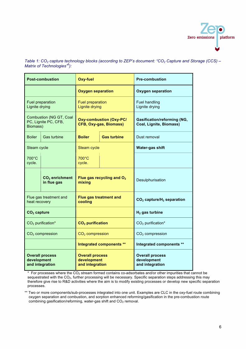
6
Table 1: CO2 capture technology blocks (according to ZEP’s document: “CO2 Capture and Storage (CCS) – Matrix of Technologies”6):
* For processes where the CO2 stream formed contains co-adsorbates and/or other impurities that cannot be sequestrated with the CO2, further processing will be necessary. Specific separation steps addressing this may therefore give rise to R&D activities where the aim is to modify existing processes or develop new specific separation processes.
** Two or more components/sub-processes integrated into one unit. Examples are CLC in the oxy-fuel route combining oxygen separation and combustion, and sorption enhanced reforming/gasification in the pre-combustion route combining gasification/reforming, water-gas shift and CO2 removal.
Post-combustion Oxy-fuel Pre-combustion
Oxygen separation Oxygen separation
Fuel preparation Lignite drying
Fuel preparation Lignite drying
Fuel handling Lignite drying
Combustion (NG GT, Coal PC, Lignite PC, CFB, Biomass)
Oxy-combustion (Oxy-PC/ CFB, Oxy-gas, Biomass)
Gasification/reforming (NG, Coal, Lignite, Biomass)
Boiler Gas turbine Boiler Gas turbine Dust removal
Steam cycle Steam cycle Water-gas shift
700°C cycle. 700°C
cycle.
CO2 enrichment in flue gas
Flue gas recycling and O2 mixing Desulphurisation
Flue gas treatment and heat recovery
Flue gas treatment and cooling CO2 capture/H2 separation
CO2 capture H2 gas turbine
CO2 purification* CO2 purification CO2 purification*
CO2 compression CO2 compression CO2 compression
Integrated components ** Integrated components **
Overall process development and integration
Overall process development and integration
Overall process development and integration
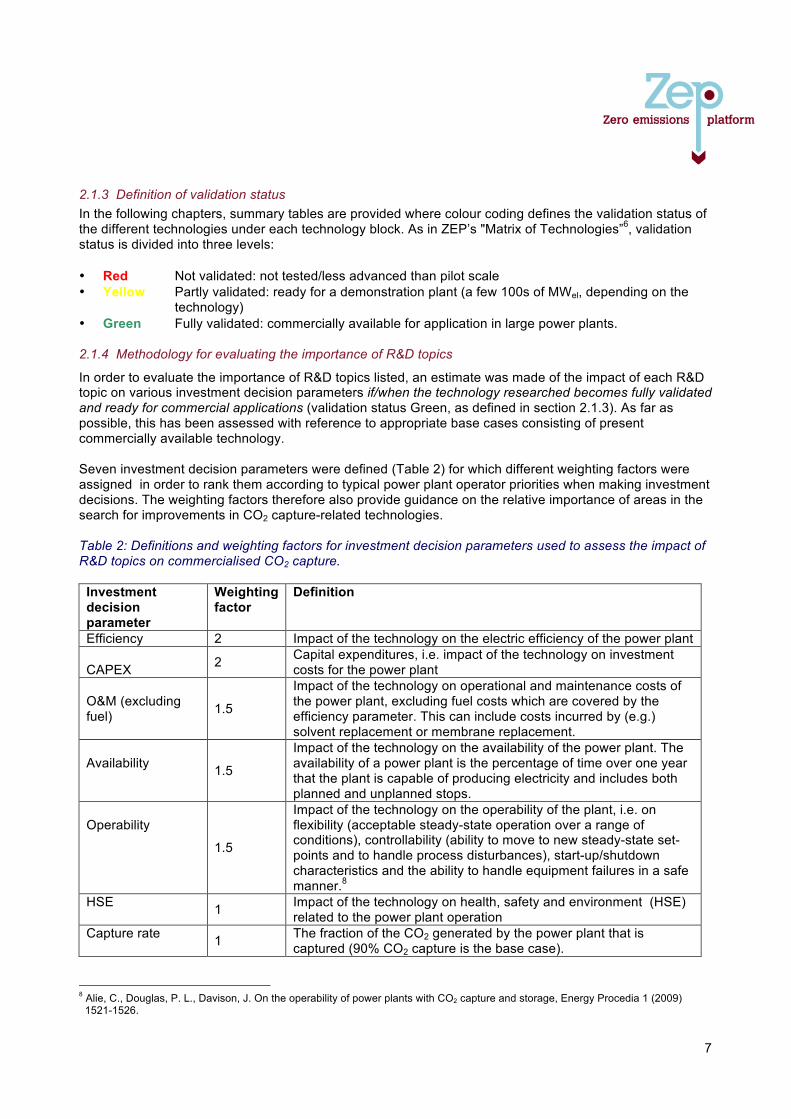
7
2.1.3 Definition of validation status In the following chapters, summary tables are provided where colour coding defines the validation status of the different technologies under each technology block. As in ZEP’s "Matrix of Technologies”6, validation status is divided into three levels: • Red Not validated: not tested/less advanced than pilot scale • Yellow Partly validated: ready for a demonstration plant (a few 100s of MWel, depending on the
technology) • Green Fully validated: commercially available for application in large power plants. 2.1.4 Methodology for evaluating the importance of R&D topics
In order to evaluate the importance of R&D topics listed, an estimate was made of the impact of each R&D topic on various investment decision parameters if/when the technology researched becomes fully validated and ready for commercial applications (validation status Green, as defined in section 2.1.3). As far as possible, this has been assessed with reference to appropriate base cases consisting of present commercially available technology. Seven investment decision parameters were defined (Table 2) for which different weighting factors were assigned in order to rank them according to typical power plant operator priorities when making investment decisions. The weighting factors therefore also provide guidance on the relative importance of areas in the search for improvements in CO2 capture-related technologies. Table 2: Definitions and weighting factors for investment decision parameters used to assess the impact of R&D topics on commercialised CO2 capture.
Investment decision parameter
Weighting factor
Definition
Efficiency 2 Impact of the technology on the electric efficiency of the power plant CAPEX 2 Capital expenditures, i.e. impact of the technology on investment
costs for the power plant O&M (excluding fuel) 1.5
Impact of the technology on operational and maintenance costs of the power plant, excluding fuel costs which are covered by the efficiency parameter. This can include costs incurred by (e.g.) solvent replacement or membrane replacement.
Availability 1.5
Impact of the technology on the availability of the power plant. The availability of a power plant is the percentage of time over one year that the plant is capable of producing electricity and includes both planned and unplanned stops.
Operability
1.5
Impact of the technology on the operability of the plant, i.e. on flexibility (acceptable steady-state operation over a range of conditions), controllability (ability to move to new steady-state set-points and to handle process disturbances), start-up/shutdown characteristics and the ability to handle equipment failures in a safe manner.8
HSE 1 Impact of the technology on health, safety and environment (HSE) related to the power plant operation
Capture rate 1 The fraction of the CO2 generated by the power plant that is captured (90% CO2 capture is the base case).
8 Alie, C., Douglas, P. L., Davison, J. On the operability of power plants with CO2 capture and storage, Energy Procedia 1 (2009) 1521-1526.

8
Motivation for assigned weighting factors When a decision is made whether to invest in a new power plant, efficiency and CAPEX are generally the two most important parameters, since these are decisive for the economy of the power plant over its lifetime. This justifies a weighting factor of 2. The costs of operation and maintenance are also important for investment decisions, although not as important as CAPEX, which justifies a weighting factor of 1.5. Furthermore, it is predicted in the EU Energy Roadmap 2050 that the share of renewable energy will rise substantially in Europe until 2050. A significant share of renewables in the power system will pose large requirements on balancing power that can be rapidly put into operation when renewables such as wind or solar power are not producing electricity. This, in turn, means that the operability of power plants with CO2 capture may become an important basis for investment decisions in the future. However, the owner's requirements on load-changing capacities could very well vary for different power plant concepts, e.g. an IGCC is likely to operate in base load, where as an NGCC is more likely to have a load following role. Altogether, the importance of power plant operability justifies a weighting factor of 1.5. The availability of power plants, i.e. the amount of time during a year that they can actually produce power, is also important when making investment decisions; and the same importance is assigned to operation and maintenance costs, excluding fuel (which is covered by the efficiency parameter). Altogether, these two parameters justify a weighting factor of 1.5. Hence, the two remaining technology parameters with the lowest weighting factors are HSE and CO2 capture rate. HSE can be regarded as a binary issue that needs no further weighting. Significantly increased negative impact on HSE from a CO2 capture technology under development is enough to halt this technology, regardless of potential improvements in efficiency and CAPEX. Improvements in HSE can also be an additional reason for pursuing an R&D topic that appears fairly promising. Assigning a weighting factor of unity to CO2 capture rate is justified by the fact that the baseline capture rate considered for the R&D topic evaluation is 90%. There are certainly technologies available which can increase CO2 capture rate beyond 90%, but it is usually possible to design the overall power plant in such a way that efficiency is increased and/or CAPEX reduced, while targeting 90% CO2 capture. Technologies that achieve a CO2 capture rate significantly below 90% will also, in an appropriate economical context, be penalised through increased O&M costs due to high CO2 emissions. Enabling activities It is not relevant to evaluate some of the R&D topics listed in section 2.2-2.5 against the technology parameters listed in Table 2. Typical examples are the development of numerical simulation tools or materials databases. The purpose of this category of R&D topics is to enable an improved capture route, rather than achieve a direct technology improvement. (Enabling activities are marked “EA” in the summary tables in sections 2.2-2.5). It must be emphasised that the conclusions and recommendations in section 2.6 are based on estimates of the impact of different R&D topics, according to the current level of knowledge within ZEP. The level of knowledge is also different for different parameters, with the greatest knowledge available for efficiency, capture rate and CAPEX, which are generally the research areas first explored for a novel technology. Operability and availability are still, to a large extent, unexplored research areas. 2.2 Post-combustion technologies
2.2.1 CO2 capture in post-combustion applications
Post-combustion capture technologies can, in principle, be applied to flue gases from all kinds of industrial processes, in particular power production from fossil fuels and biomass, cement, steel and aluminium production. Several separation principles are relevant. Absorption based on liquid chemical solvents (amines) is currently the leading and most developed technology. Further along the timeline, high

9
temperature calcium looping cycles, which have undergone a fast development process in recent years, is seen as a potential candidate; also membrane separation and adsorption by low temperature solid sorbents are potential candidates in the longer term. Key challenges and long-term R&D targets • Flexible operation of integrated capture and power plants.
Long-term R&D target: develop processes that enable the integrated plant to respond quickly and efficiently to changes in power and carbon markets.
• The high energy requirement of the separation process; a penalty of ~10% points in efficiency loss with present technology (MEA). A long-term R&D target (beyond 2030) should be to reduce this to below 5% points.
• The low CO2 partial pressure (especially for NG power plants) and the large flue gas volumes imply very large equipment volumes and contacting surfaces. Long-term R&D target: reduce equipment volumes by developing more effective contacting surfaces.
• Flue gas impurities (depending on fuel). Long-term R&D target: develop capture processes independent from, or at least very robust with respect to composition of impurities in the flue gas. Develop capture processes which can efficiently co-capture impurities of larger concentration (e.g. SO2).
• Degradation and environmental aspects. Long-term R&D target: develop processes with very low overall emission levels (e.g. degradation products) and in line measurement techniques for very low concentrations.
• Material of construction Long-term R&D target: develop lower cost materials for construction of capture plants.
R&D needs • Liquid absorbents: liquid solvents need to have a lower energy requirement for regeneration than
today, be non-toxic and environmentally friendly. They should also be robust against flue gas impurities and have a low degradation rate. In order to decrease CAPEX and OPEX, technological development of gas/liquid contactors is also necessary (including also membrane contactors). Research on this type of solvent is ongoing and progressing, but is likely to continue beyond 2020. Systems using additional effects such as precipitation, pH swing and liquid extraction will probably play an important part in their development. Adaptation of capture and power process configurations is also necessary to make best use of these improved solvents.
• Calcium looping (or carbonate looping) is a chemical looping type of process that uses CaO particles to react with CO2 in the flue gas. In recent years, this process has reached MWth pilot scale, using existing Circulating Fluidised Bed technology in the carbonator reactor. The subsequent calcination of CaCO3 in an oxyfired CFBC (see 2.3.2) regenerates the CaO and returns CO2. The overall efficiency penalty can approach 6% points. R&D issues are: scaling up of Circulating Fluidised Bed carbonator and experimental validation at increasing scales, alternative calciner designs, CO2 sorbent performance issues related to chemical and mechanical stability, integration of purge uses, combined SO2 capture and low-cost reactivation processes.
• High-temperature solid sorbents other than natural CaO/CaCO3.
• Low-temperature solid sorbent (amines supported on carbon, metal oxide frameworks etc.) are being investigated as alternative functional materials for post-combustion CO2 capture. High adsorption rates, selectivities and capacities under low partial pressures of CO2 are needed for these materials to be suitable for large-scale CO2 capture.
• Membranes: the application of membranes in fossil fuel power plants requires large membranes that can be maintained and repaired. They also have to withstand pollution, fouling, as well as temperature
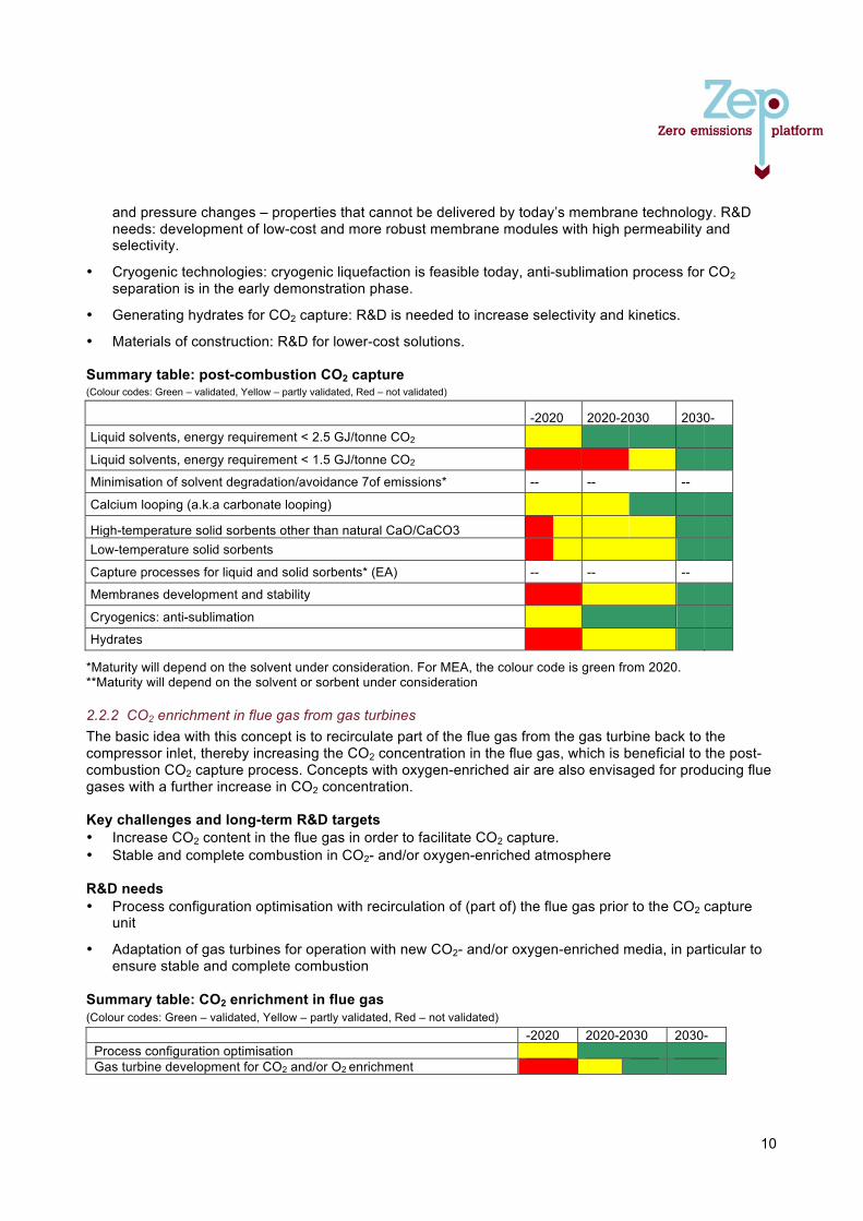
10
and pressure changes – properties that cannot be delivered by today’s membrane technology. R&D needs: development of low-cost and more robust membrane modules with high permeability and selectivity.
• Cryogenic technologies: cryogenic liquefaction is feasible today, anti-sublimation process for CO2 separation is in the early demonstration phase.
• Generating hydrates for CO2 capture: R&D is needed to increase selectivity and kinetics.
• Materials of construction: R&D for lower-cost solutions. Summary table: post-combustion CO2 capture (Colour codes: Green – validated, Yellow – partly validated, Red – not validated)
-2020 2020-2030 2030-
Liquid solvents, energy requirement < 2.5 GJ/tonne CO2
Liquid solvents, energy requirement < 1.5 GJ/tonne CO2
Minimisation of solvent degradation/avoidance 7of emissions* -- -- --
Calcium looping (a.k.a carbonate looping)
High-temperature solid sorbents other than natural CaO/CaCO3
Low-temperature solid sorbents
Capture processes for liquid and solid sorbents* (EA) -- -- --
Membranes development and stability
Cryogenics: anti-sublimation
Hydrates
*Maturity will depend on the solvent under consideration. For MEA, the colour code is green from 2020. **Maturity will depend on the solvent or sorbent under consideration
2.2.2 CO2 enrichment in flue gas from gas turbines The basic idea with this concept is to recirculate part of the flue gas from the gas turbine back to the compressor inlet, thereby increasing the CO2 concentration in the flue gas, which is beneficial to the post-combustion CO2 capture process. Concepts with oxygen-enriched air are also envisaged for producing flue gases with a further increase in CO2 concentration. Key challenges and long-term R&D targets • Increase CO2 content in the flue gas in order to facilitate CO2 capture. • Stable and complete combustion in CO2- and/or oxygen-enriched atmosphere R&D needs • Process configuration optimisation with recirculation of (part of) the flue gas prior to the CO2 capture
unit
• Adaptation of gas turbines for operation with new CO2- and/or oxygen-enriched media, in particular to ensure stable and complete combustion
Summary table: CO2 enrichment in flue gas (Colour codes: Green – validated, Yellow – partly validated, Red – not validated)
-2020 2020-2030 2030- Process configuration optimisation Gas turbine development for CO2 and/or O2 enrichment
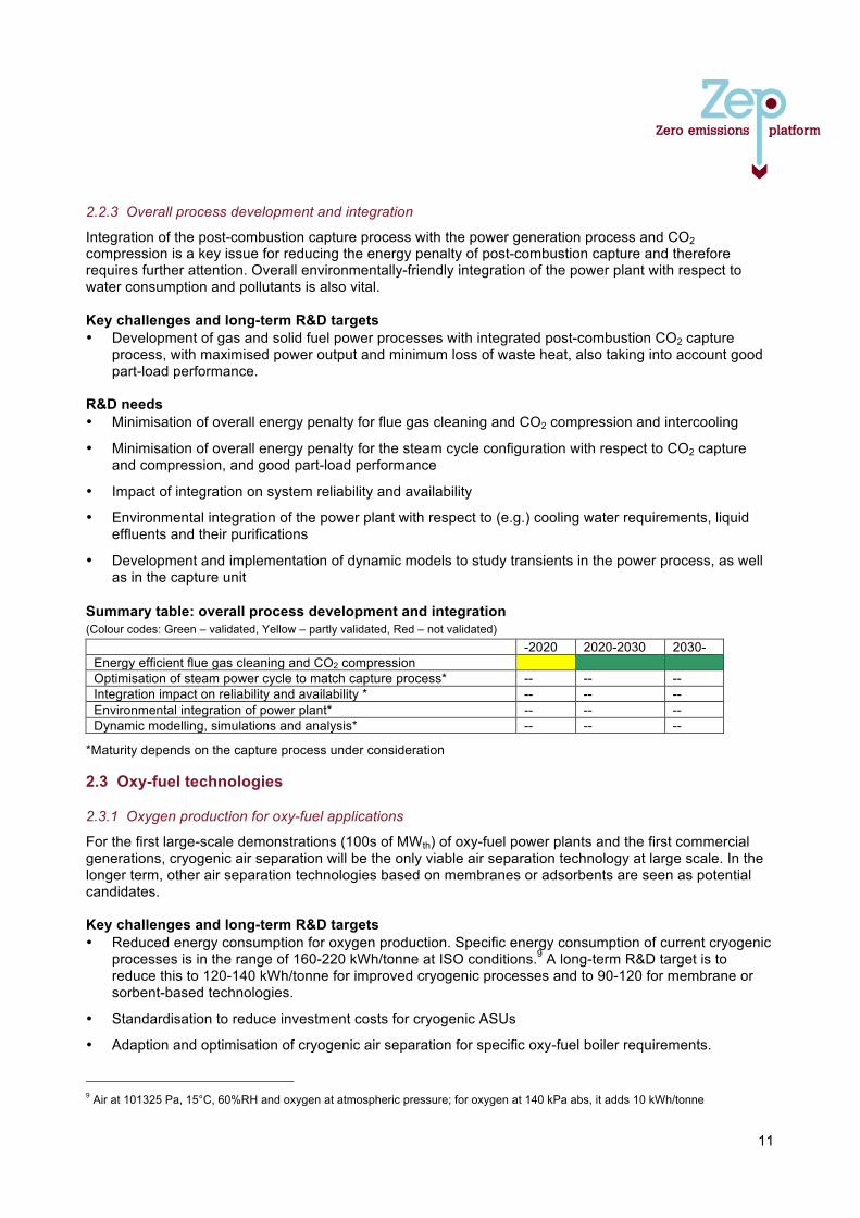
11
2.2.3 Overall process development and integration
Integration of the post-combustion capture process with the power generation process and CO2 compression is a key issue for reducing the energy penalty of post-combustion capture and therefore requires further attention. Overall environmentally-friendly integration of the power plant with respect to water consumption and pollutants is also vital. Key challenges and long-term R&D targets • Development of gas and solid fuel power processes with integrated post-combustion CO2 capture
process, with maximised power output and minimum loss of waste heat, also taking into account good part-load performance.
R&D needs • Minimisation of overall energy penalty for flue gas cleaning and CO2 compression and intercooling
• Minimisation of overall energy penalty for the steam cycle configuration with respect to CO2 capture and compression, and good part-load performance
• Impact of integration on system reliability and availability
• Environmental integration of the power plant with respect to (e.g.) cooling water requirements, liquid effluents and their purifications
• Development and implementation of dynamic models to study transients in the power process, as well as in the capture unit
Summary table: overall process development and integration (Colour codes: Green – validated, Yellow – partly validated, Red – not validated)
-2020 2020-2030 2030- Energy efficient flue gas cleaning and CO2 compression Optimisation of steam power cycle to match capture process* -- -- -- Integration impact on reliability and availability * -- -- -- Environmental integration of power plant* -- -- -- Dynamic modelling, simulations and analysis* -- -- --
*Maturity depends on the capture process under consideration 2.3 Oxy-fuel technologies
2.3.1 Oxygen production for oxy-fuel applications
For the first large-scale demonstrations (100s of MWth) of oxy-fuel power plants and the first commercial generations, cryogenic air separation will be the only viable air separation technology at large scale. In the longer term, other air separation technologies based on membranes or adsorbents are seen as potential candidates. Key challenges and long-term R&D targets • Reduced energy consumption for oxygen production. Specific energy consumption of current cryogenic
processes is in the range of 160-220 kWh/tonne at ISO conditions.9 A long-term R&D target is to reduce this to 120-140 kWh/tonne for improved cryogenic processes and to 90-120 for membrane or sorbent-based technologies.
• Standardisation to reduce investment costs for cryogenic ASUs
• Adaption and optimisation of cryogenic air separation for specific oxy-fuel boiler requirements. 9 Air at 101325 Pa, 15°C, 60%RH and oxygen at atmospheric pressure; for oxygen at 140 kPa abs, it adds 10 kWh/tonne
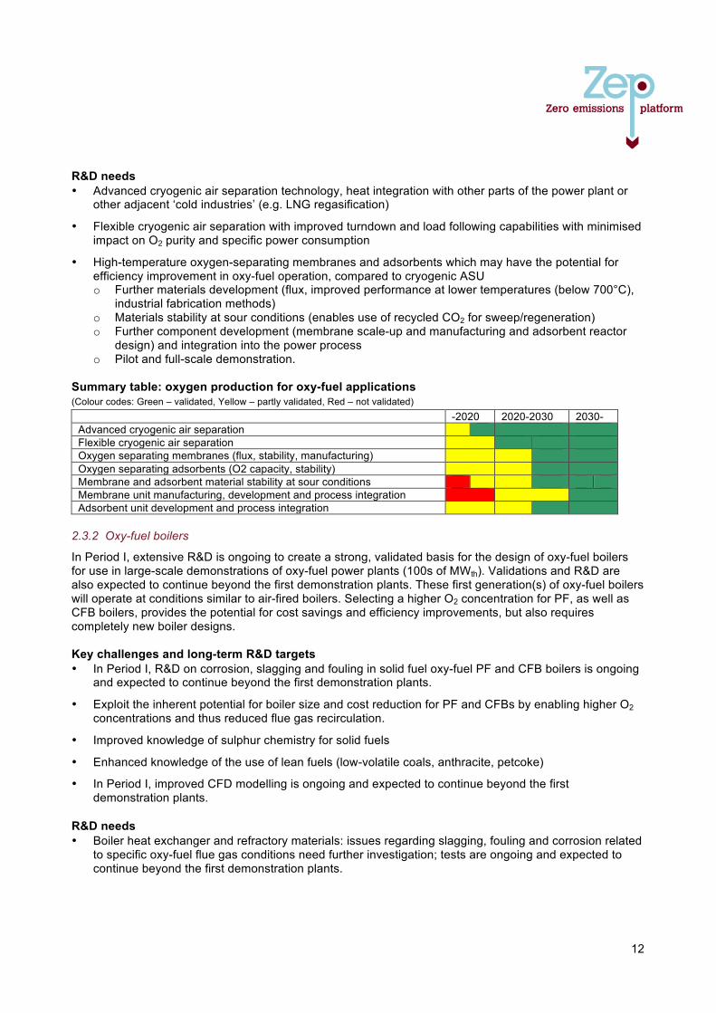
12
R&D needs • Advanced cryogenic air separation technology, heat integration with other parts of the power plant or
other adjacent ‘cold industries’ (e.g. LNG regasification)
• Flexible cryogenic air separation with improved turndown and load following capabilities with minimised impact on O2 purity and specific power consumption
• High-temperature oxygen-separating membranes and adsorbents which may have the potential for efficiency improvement in oxy-fuel operation, compared to cryogenic ASU o Further materials development (flux, improved performance at lower temperatures (below 700°C),
industrial fabrication methods) o Materials stability at sour conditions (enables use of recycled CO2 for sweep/regeneration) o Further component development (membrane scale-up and manufacturing and adsorbent reactor
design) and integration into the power process o Pilot and full-scale demonstration.
Summary table: oxygen production for oxy-fuel applications (Colour codes: Green – validated, Yellow – partly validated, Red – not validated)
-2020 2020-2030 2030- Advanced cryogenic air separation Flexible cryogenic air separation Oxygen separating membranes (flux, stability, manufacturing) Oxygen separating adsorbents (O2 capacity, stability) Membrane and adsorbent material stability at sour conditions Membrane unit manufacturing, development and process integration Adsorbent unit development and process integration
2.3.2 Oxy-fuel boilers
In Period I, extensive R&D is ongoing to create a strong, validated basis for the design of oxy-fuel boilers for use in large-scale demonstrations of oxy-fuel power plants (100s of MWth). Validations and R&D are also expected to continue beyond the first demonstration plants. These first generation(s) of oxy-fuel boilers will operate at conditions similar to air-fired boilers. Selecting a higher O2 concentration for PF, as well as CFB boilers, provides the potential for cost savings and efficiency improvements, but also requires completely new boiler designs. Key challenges and long-term R&D targets • In Period I, R&D on corrosion, slagging and fouling in solid fuel oxy-fuel PF and CFB boilers is ongoing
and expected to continue beyond the first demonstration plants.
• Exploit the inherent potential for boiler size and cost reduction for PF and CFBs by enabling higher O2 concentrations and thus reduced flue gas recirculation.
• Improved knowledge of sulphur chemistry for solid fuels
• Enhanced knowledge of the use of lean fuels (low-volatile coals, anthracite, petcoke)
• In Period I, improved CFD modelling is ongoing and expected to continue beyond the first demonstration plants.
R&D needs • Boiler heat exchanger and refractory materials: issues regarding slagging, fouling and corrosion related
to specific oxy-fuel flue gas conditions need further investigation; tests are ongoing and expected to continue beyond the first demonstration plants.
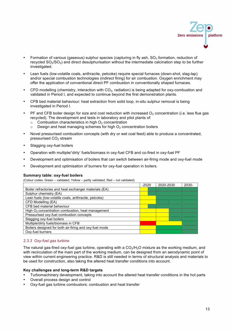
13
• Formation of various (gaseous) sulphur species (capturing in fly ash, SO3 formation, reduction of recycled SO2/SO3) and direct desulphurisation without the intermediate calcination step to be further investigated.
• Lean fuels (low-volatile coals, anthracite, petcoke) require special furnaces (down-shot, slag-tap) and/or special combustion technologies (indirect firing) for air combustion. Oxygen enrichment may offer the application of conventional direct PF combustion in conventionally shaped furnaces.
• CFD modelling (chemistry, interaction with CO2, radiation) is being adapted for oxy-combustion and validated in Period I, and expected to continue beyond the first demonstration plants.
• CFB bed material behaviour: heat extraction from solid loop, in-situ sulphur removal is being investigated in Period I.
• PF and CFB boiler design for size and cost reduction with increased O2 concentration (i.e. less flue gas recycled). The development and tests in laboratory and pilot plants of: o Combustion characteristics in high O2 concentration o Design and heat managing schemes for high O2 concentration boilers
• Novel pressurised combustion concepts (with dry or wet coal feed) able to produce a concentrated, pressurised CO2 stream
• Slagging oxy-fuel boilers
• Operation with multiple/‘dirty’ fuels/biomass in oxy-fuel CFB and co-fired in oxy-fuel PF
• Development and optimisation of boilers that can switch between air-firing mode and oxy-fuel mode
• Development and optimisation of burners for oxy-fuel operation in boilers.
Summary table: oxy-fuel boilers (Colour codes: Green – validated, Yellow – partly validated, Red – not validated)
-2020 2020-2030 2030- Boiler refractories and heat exchanger materials (EA) Sulphur chemistry (EA) Lean fuels (low-volatile coals, anthracite, petcoke) CFD Modelling (EA) CFB bed material behaviour High O2 concentration combustion, heat management Pressurised oxy-fuel combustion concepts Slagging oxy-fuel boilers Multiple/dirty fuels/biomass in CFB Boilers designed for both air-firing and oxy-fuel mode Oxy-fuel burners
2.3.3 Oxy-fuel gas turbine
The natural gas-fired oxy-fuel gas turbine, operating with a CO2/H2O mixture as the working medium, and with recirculation of the main part of the working medium, can be designed from an aerodynamic point of view within current engineering practice. R&D is still needed in terms of structural analysis and materials to be used for construction, also taking the altered heat transfer conditions into account. Key challenges and long-term R&D targets • Turbomachinery development, taking into account the altered heat transfer conditions in the hot parts • Overall process design and control • Oxy-fuel gas turbine combustors: combustion and heat transfer
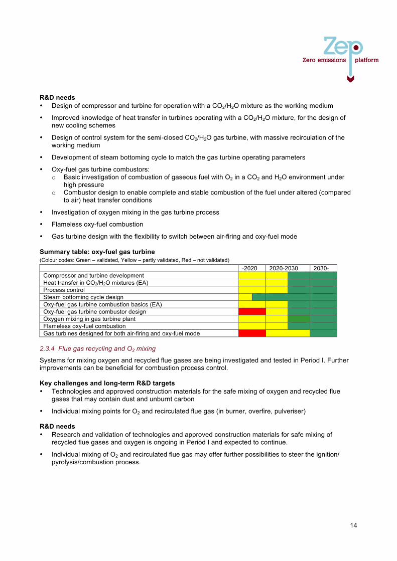
14
R&D needs • Design of compressor and turbine for operation with a CO2/H2O mixture as the working medium
• Improved knowledge of heat transfer in turbines operating with a CO2/H2O mixture, for the design of new cooling schemes
• Design of control system for the semi-closed CO2/H2O gas turbine, with massive recirculation of the working medium
• Development of steam bottoming cycle to match the gas turbine operating parameters
• Oxy-fuel gas turbine combustors: o Basic investigation of combustion of gaseous fuel with O2 in a CO2 and H2O environment under
high pressure o Combustor design to enable complete and stable combustion of the fuel under altered (compared
to air) heat transfer conditions
• Investigation of oxygen mixing in the gas turbine process
• Flameless oxy-fuel combustion
• Gas turbine design with the flexibility to switch between air-firing and oxy-fuel mode Summary table: oxy-fuel gas turbine (Colour codes: Green – validated, Yellow – partly validated, Red – not validated)
-2020 2020-2030 2030- Compressor and turbine development Heat transfer in CO2/H2O mixtures (EA) Process control Steam bottoming cycle design Oxy-fuel gas turbine combustion basics (EA) Oxy-fuel gas turbine combustor design Oxygen mixing in gas turbine plant Flameless oxy-fuel combustion Gas turbines designed for both air-firing and oxy-fuel mode
2.3.4 Flue gas recycling and O2 mixing
Systems for mixing oxygen and recycled flue gases are being investigated and tested in Period I. Further improvements can be beneficial for combustion process control. Key challenges and long-term R&D targets • Technologies and approved construction materials for the safe mixing of oxygen and recycled flue
gases that may contain dust and unburnt carbon
• Individual mixing points for O2 and recirculated flue gas (in burner, overfire, pulveriser) R&D needs • Research and validation of technologies and approved construction materials for safe mixing of
recycled flue gases and oxygen is ongoing in Period I and expected to continue.
• Individual mixing of O2 and recirculated flue gas may offer further possibilities to steer the ignition/ pyrolysis/combustion process.
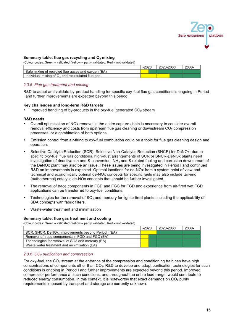
15
Summary table: flue gas recycling and O2 mixing (Colour codes: Green – validated, Yellow – partly validated, Red – not validated)
-2020 2020-2030 2030- Safe mixing of recycled flue gases and oxygen (EA) Individual mixing of O2 and recirculated flue gas
2.3.5 Flue gas treatment and cooling
R&D to adapt and validate by-product handling for specific oxy-fuel flue gas conditions is ongoing in Period I and further improvements are expected beyond this period. Key challenges and long-term R&D targets • Improved handling of by-products in the oxy-fuel generated CO2 stream R&D needs • Overall optimisation of NOx removal in the entire capture chain is necessary to consider overall
removal efficiency and costs from upstream flue gas cleaning or downstream CO2 compression processes, or a combination of both options.
• Emission control from air-firing to oxy-fuel combustion could be a topic for flue gas cleaning design and operation.
• Selective Catalytic Reduction (SCR), Selective Non-Catalytic Reduction (SNCR) for DeNOx: due to specific oxy-fuel flue gas conditions, high-dust arrangements of SCR or SNCR-DeNOx plants need investigation of deactivation and S-conversion. NH3 and S related fouling and corrosion downstream of the DeNOx plant may also be an issue. These issues are being investigated in Period I and continued R&D on improvements is expected. Optimal locations for de-NOx from a system point of view and technical and economically optimal de-NOx concepts for specific fuels may also include tail-end (authothermal) catalytic de-NOx concepts that should be further investigated.
• The removal of trace components in FGD and FGC for FGD and experience from air-fired wet FGD applications can be transferred to oxy-fuel conditions.
• Technologies for the removal of SO3 and mercury for lignite-fired plants, including the applicability of SDA concepts with fabric filters.
• Waste-water treatment and minimisation Summary table: flue gas treatment and cooling (Colour codes: Green – validated, Yellow – partly validated, Red – not validated)
-2020 2020-2030 2030- SCR, SNCR, DeNOx, improvements beyond Period I (EA) Removal of trace components in FGD and FGC (EA) Technologies for removal of SO3 and mercury (EA) Waste water treatment and minimisation (EA)
2.3.6 CO2 purification and compression
For oxy-fuel, the CO2 stream at the entrance of the compression and conditioning train can have high concentrations of components other than CO2. R&D to develop and adapt purification technologies for such conditions is ongoing in Period I and further improvements are expected beyond this period. Improved compressor performance at such conditions, and throughout the entire load range, would contribute to reduced energy consumption. In this context, it is noteworthy that exact demands on CO2 purity requirements imposed by transport and storage are currently unknown.
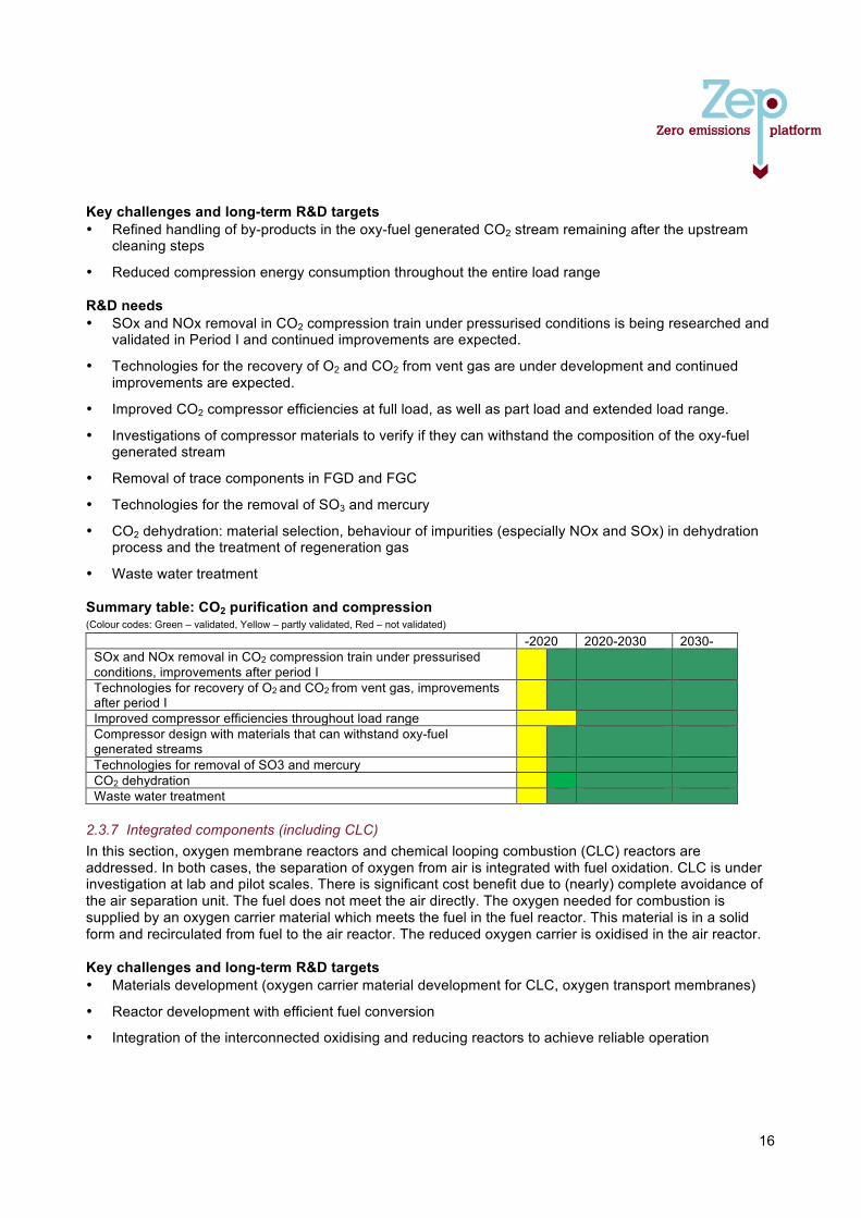
16
Key challenges and long-term R&D targets • Refined handling of by-products in the oxy-fuel generated CO2 stream remaining after the upstream
cleaning steps
• Reduced compression energy consumption throughout the entire load range R&D needs • SOx and NOx removal in CO2 compression train under pressurised conditions is being researched and
validated in Period I and continued improvements are expected.
• Technologies for the recovery of O2 and CO2 from vent gas are under development and continued improvements are expected.
• Improved CO2 compressor efficiencies at full load, as well as part load and extended load range.
• Investigations of compressor materials to verify if they can withstand the composition of the oxy-fuel generated stream
• Removal of trace components in FGD and FGC
• Technologies for the removal of SO3 and mercury
• CO2 dehydration: material selection, behaviour of impurities (especially NOx and SOx) in dehydration process and the treatment of regeneration gas
• Waste water treatment Summary table: CO2 purification and compression (Colour codes: Green – validated, Yellow – partly validated, Red – not validated)
-2020 2020-2030 2030- SOx and NOx removal in CO2 compression train under pressurised conditions, improvements after period I
Technologies for recovery of O2 and CO2 from vent gas, improvements after period I
Improved compressor efficiencies throughout load range Compressor design with materials that can withstand oxy-fuel generated streams
Technologies for removal of SO3 and mercury CO2 dehydration Waste water treatment
2.3.7 Integrated components (including CLC) In this section, oxygen membrane reactors and chemical looping combustion (CLC) reactors are addressed. In both cases, the separation of oxygen from air is integrated with fuel oxidation. CLC is under investigation at lab and pilot scales. There is significant cost benefit due to (nearly) complete avoidance of the air separation unit. The fuel does not meet the air directly. The oxygen needed for combustion is supplied by an oxygen carrier material which meets the fuel in the fuel reactor. This material is in a solid form and recirculated from fuel to the air reactor. The reduced oxygen carrier is oxidised in the air reactor. Key challenges and long-term R&D targets • Materials development (oxygen carrier material development for CLC, oxygen transport membranes)
• Reactor development with efficient fuel conversion
• Integration of the interconnected oxidising and reducing reactors to achieve reliable operation

17
R&D needs • Chemical Looping Combustion:
o Oxygen carriers (synthetically generated, naturally existing, oxygen capacity and kinetics, mechanical and chemical stability, toxicity).
o Development of various oxygen carriers for variable fuels (coal, gas, biomass, multiple fuels) o Fuel conversion, including avoidance of not fully converted compounds (CO, H2, CH4, H2S) o Validation and scale-up of oxygen carrier and ash separation o Reactor design, structural optimisation and scale-up o Use of advanced materials (e.g. ceramics, composites etc.) in reactor design o Scale-up o Integration into the power process o Pressurised reactors dedicated to gas-turbine operation o Pressurised reactors for coal, for improved kinetics
• Oxygen transport membrane (OTM) reactors: materials development, reactor development, reactor temperature control
• Integration of new oxygen separation technologies (i.e. membranes and/or adsorbent processes) with oxy-fuel boilers
Summary table: integrated components (Colour codes: Green – validated, Yellow – partly validated, Red – not validated)
-2020 2020-2030 2030- CLC Oxygen carrier materials development for gas, coal, biomass or multiple fuels
O2 carrier material stability at high T, sour and wet environment CLC Fuel conversion CLC Oxygen carrier/ash separation CLC Reactor design, optimisation and scale-up CLC pressurised reactors for gas turbine operation CLC pressurised reactors for coal CLC reactor power process integration OTM materials and reactor development Integration of new oxygen separation technologies with oxy-fuel boilers
2.3.8 Overall process development and integration
For pilot, demonstration/full-scale testing of PF and CFB oxy-fuel power plants (10s to 100s of MW), the design of larger-size plants is based on research findings from smaller-scale plants, combined with findings from the sections listed above. As the knowledge of oxy-fuel operation increases with the number of plants, new possibilities for process integration will be easier to identify. Key challenges and long-term R&D targets • Scale-up and validations of oxy-fuel power plants with minimum energy penalty. This covers
optimisation of heat integration and heat recovery of the entire system, including ASU and compression.
R&D needs • Validations in pilot plants followed by demonstration plants with associated R&D programmes
• Impact of integration on system reliability and availability
• New/improved technology blocks will require subsequent validations of integration issues in pilots and demonstration plants.
• Plant integration and optimisation for efficiency and cost, including part-load performance
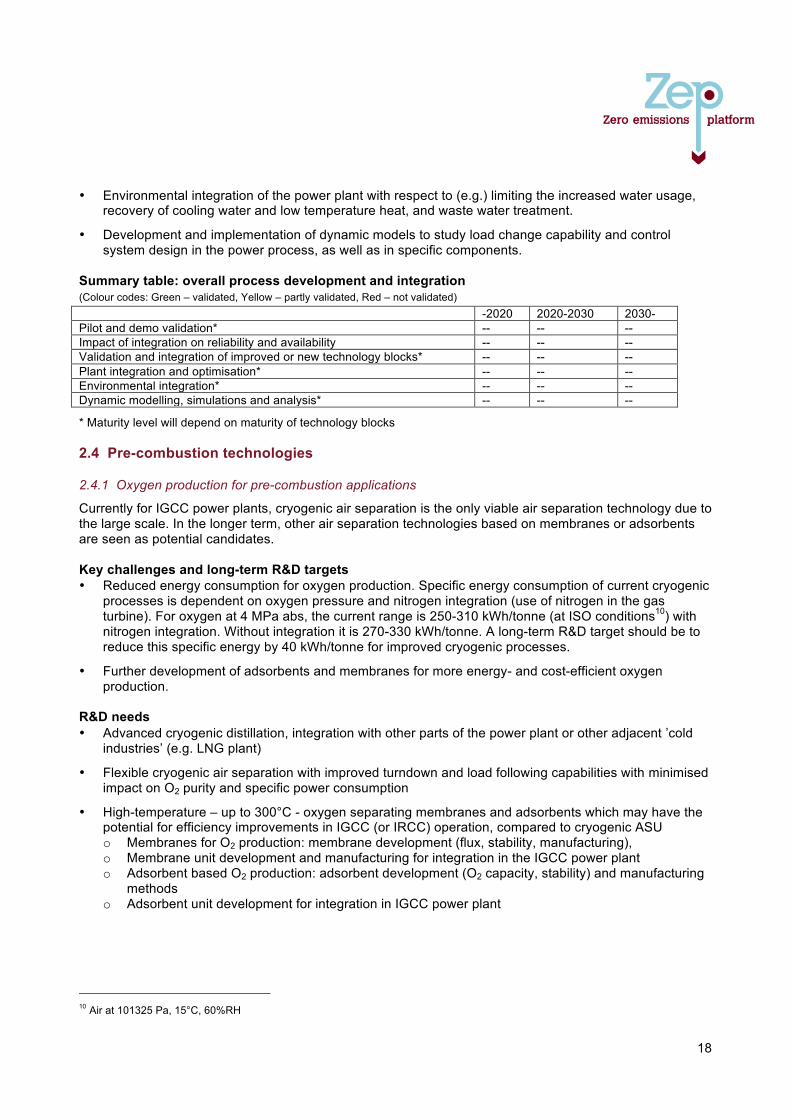
18
• Environmental integration of the power plant with respect to (e.g.) limiting the increased water usage, recovery of cooling water and low temperature heat, and waste water treatment.
• Development and implementation of dynamic models to study load change capability and control system design in the power process, as well as in specific components.
Summary table: overall process development and integration (Colour codes: Green – validated, Yellow – partly validated, Red – not validated) -2020 2020-2030 2030- Pilot and demo validation* -- -- -- Impact of integration on reliability and availability -- -- -- Validation and integration of improved or new technology blocks* -- -- -- Plant integration and optimisation* -- -- -- Environmental integration* -- -- -- Dynamic modelling, simulations and analysis* -- -- --
* Maturity level will depend on maturity of technology blocks 2.4 Pre-combustion technologies
2.4.1 Oxygen production for pre-combustion applications
Currently for IGCC power plants, cryogenic air separation is the only viable air separation technology due to the large scale. In the longer term, other air separation technologies based on membranes or adsorbents are seen as potential candidates. Key challenges and long-term R&D targets • Reduced energy consumption for oxygen production. Specific energy consumption of current cryogenic
processes is dependent on oxygen pressure and nitrogen integration (use of nitrogen in the gas turbine). For oxygen at 4 MPa abs, the current range is 250-310 kWh/tonne (at ISO conditions10) with nitrogen integration. Without integration it is 270-330 kWh/tonne. A long-term R&D target should be to reduce this specific energy by 40 kWh/tonne for improved cryogenic processes.
• Further development of adsorbents and membranes for more energy- and cost-efficient oxygen production.
R&D needs • Advanced cryogenic distillation, integration with other parts of the power plant or other adjacent ’cold
industries’ (e.g. LNG plant)
• Flexible cryogenic air separation with improved turndown and load following capabilities with minimised impact on O2 purity and specific power consumption
• High-temperature – up to 300°C - oxygen separating membranes and adsorbents which may have the potential for efficiency improvements in IGCC (or IRCC) operation, compared to cryogenic ASU o Membranes for O2 production: membrane development (flux, stability, manufacturing), o Membrane unit development and manufacturing for integration in the IGCC power plant o Adsorbent based O2 production: adsorbent development (O2 capacity, stability) and manufacturing
methods o Adsorbent unit development for integration in IGCC power plant
10 Air at 101325 Pa, 15°C, 60%RH
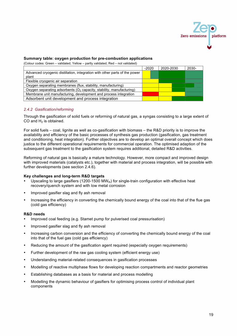
19
Summary table: oxygen production for pre-combustion applications (Colour codes: Green – validated, Yellow – partly validated, Red – not validated)
-2020 2020-2030 2030- Advanced cryogenic distillation, integration with other parts of the power plant
Flexible cryogenic air separation Oxygen separating membranes (flux, stability, manufacturing) Oxygen separating adsorbents (O2 capacity, stability, manufacturing) Membrane unit manufacturing, development and process integration Adsorbent unit development and process integration
2.4.2 Gasification/reforming
Through the gasification of solid fuels or reforming of natural gas, a syngas consisting to a large extent of CO and H2 is obtained. For solid fuels – coal, lignite as well as co-gasification with biomass – the R&D priority is to improve the availability and efficiency of the basic processes of synthesis gas production (gasification, gas treatment and conditioning, heat integration). Further objectives are to develop an optimal overall concept which does justice to the different operational requirements for commercial operation. The optimised adaption of the subsequent gas treatment to the gasification system requires additional, detailed R&D activities. Reforming of natural gas is basically a mature technology. However, more compact and improved design with improved materials (catalysts etc.), together with material and process integration, will be possible with further developments (see section 2.4.6). Key challenges and long-term R&D targets • Upscaling to large gasifiers (1200-1500 MWth) for single-train configuration with effective heat
recovery/quench system and with low metal corrosion
• Improved gasifier slag and fly ash removal
• Increasing the efficiency in converting the chemically bound energy of the coal into that of the flue gas (cold gas efficiency)
R&D needs • Improved coal feeding (e.g. Stamet pump for pulverised coal pressurisation)
• Improved gasifier slag and fly ash removal
• Increasing carbon conversion and the efficiency of converting the chemically bound energy of the coal into that of the fuel gas (cold gas efficiency)
• Reducing the amount of the gasification agent required (especially oxygen requirements)
• Further development of the raw gas cooling system (efficient energy use)
• Understanding material-related consequences in gasification processes
• Modelling of reactive multiphase flows for developing reaction compartments and reactor geometries
• Establishing databases as a basis for material and process modelling
• Modelling the dynamic behaviour of gasifiers for optimising process control of individual plant components
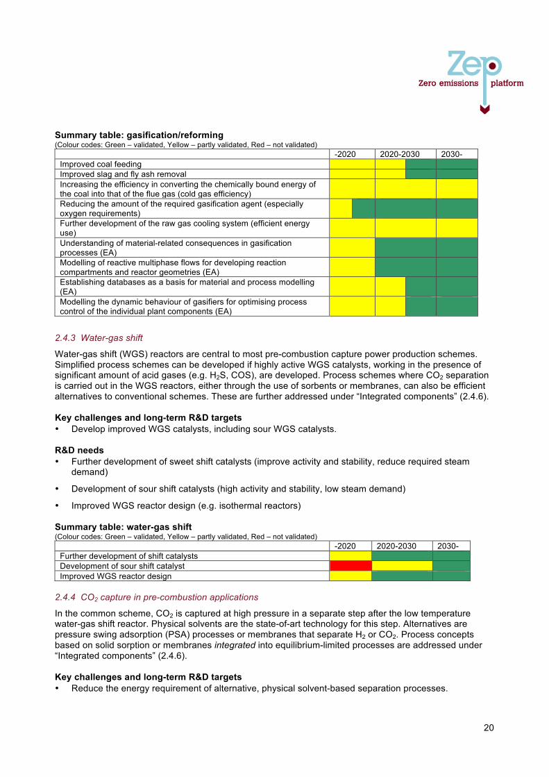
20
Summary table: gasification/reforming (Colour codes: Green – validated, Yellow – partly validated, Red – not validated)
-2020 2020-2030 2030- Improved coal feeding Improved slag and fly ash removal Increasing the efficiency in converting the chemically bound energy of the coal into that of the flue gas (cold gas efficiency)
Reducing the amount of the required gasification agent (especially oxygen requirements)
Further development of the raw gas cooling system (efficient energy use)
Understanding of material-related consequences in gasification processes (EA)
Modelling of reactive multiphase flows for developing reaction compartments and reactor geometries (EA)
Establishing databases as a basis for material and process modelling (EA)
Modelling the dynamic behaviour of gasifiers for optimising process control of the individual plant components (EA)
2.4.3 Water-gas shift
Water-gas shift (WGS) reactors are central to most pre-combustion capture power production schemes. Simplified process schemes can be developed if highly active WGS catalysts, working in the presence of significant amount of acid gases (e.g. H2S, COS), are developed. Process schemes where CO2 separation is carried out in the WGS reactors, either through the use of sorbents or membranes, can also be efficient alternatives to conventional schemes. These are further addressed under “Integrated components” (2.4.6). Key challenges and long-term R&D targets • Develop improved WGS catalysts, including sour WGS catalysts. R&D needs • Further development of sweet shift catalysts (improve activity and stability, reduce required steam
demand)
• Development of sour shift catalysts (high activity and stability, low steam demand)
• Improved WGS reactor design (e.g. isothermal reactors) Summary table: water-gas shift (Colour codes: Green – validated, Yellow – partly validated, Red – not validated)
-2020 2020-2030 2030- Further development of shift catalysts Development of sour shift catalyst Improved WGS reactor design
2.4.4 CO2 capture in pre-combustion applications
In the common scheme, CO2 is captured at high pressure in a separate step after the low temperature water-gas shift reactor. Physical solvents are the state-of-art technology for this step. Alternatives are pressure swing adsorption (PSA) processes or membranes that separate H2 or CO2. Process concepts based on solid sorption or membranes integrated into equilibrium-limited processes are addressed under “Integrated components” (2.4.6). Key challenges and long-term R&D targets • Reduce the energy requirement of alternative, physical solvent-based separation processes.
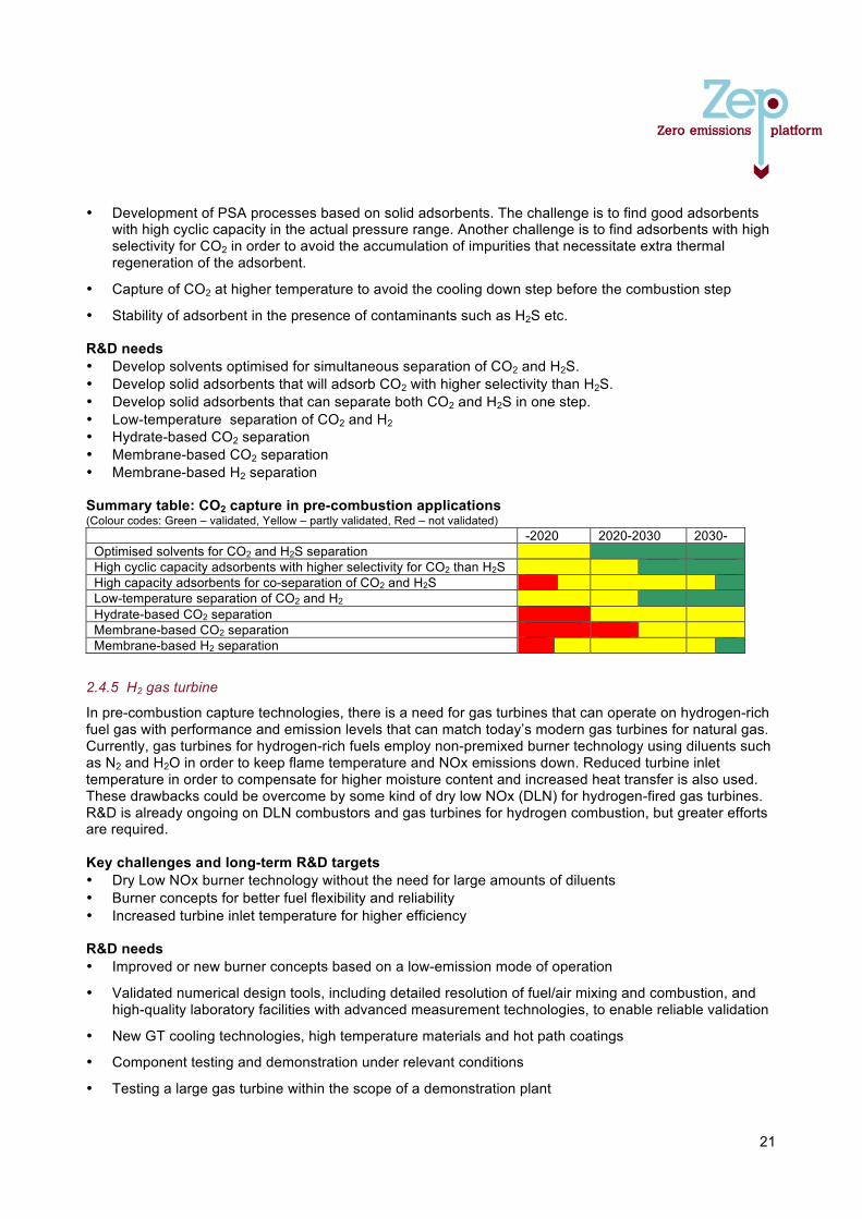
21
• Development of PSA processes based on solid adsorbents. The challenge is to find good adsorbents with high cyclic capacity in the actual pressure range. Another challenge is to find adsorbents with high selectivity for CO2 in order to avoid the accumulation of impurities that necessitate extra thermal regeneration of the adsorbent.
• Capture of CO2 at higher temperature to avoid the cooling down step before the combustion step
• Stability of adsorbent in the presence of contaminants such as H2S etc. R&D needs • Develop solvents optimised for simultaneous separation of CO2 and H2S. • Develop solid adsorbents that will adsorb CO2 with higher selectivity than H2S. • Develop solid adsorbents that can separate both CO2 and H2S in one step. • Low-temperature separation of CO2 and H2 • Hydrate-based CO2 separation • Membrane-based CO2 separation • Membrane-based H2 separation Summary table: CO2 capture in pre-combustion applications (Colour codes: Green – validated, Yellow – partly validated, Red – not validated)
-2020 2020-2030 2030- Optimised solvents for CO2 and H2S separation High cyclic capacity adsorbents with higher selectivity for CO2 than H2S High capacity adsorbents for co-separation of CO2 and H2S Low-temperature separation of CO2 and H2 Hydrate-based CO2 separation Membrane-based CO2 separation Membrane-based H2 separation
2.4.5 H2 gas turbine
In pre-combustion capture technologies, there is a need for gas turbines that can operate on hydrogen-rich fuel gas with performance and emission levels that can match today’s modern gas turbines for natural gas. Currently, gas turbines for hydrogen-rich fuels employ non-premixed burner technology using diluents such as N2 and H2O in order to keep flame temperature and NOx emissions down. Reduced turbine inlet temperature in order to compensate for higher moisture content and increased heat transfer is also used. These drawbacks could be overcome by some kind of dry low NOx (DLN) for hydrogen-fired gas turbines. R&D is already ongoing on DLN combustors and gas turbines for hydrogen combustion, but greater efforts are required. Key challenges and long-term R&D targets • Dry Low NOx burner technology without the need for large amounts of diluents • Burner concepts for better fuel flexibility and reliability • Increased turbine inlet temperature for higher efficiency R&D needs • Improved or new burner concepts based on a low-emission mode of operation
• Validated numerical design tools, including detailed resolution of fuel/air mixing and combustion, and high-quality laboratory facilities with advanced measurement technologies, to enable reliable validation
• New GT cooling technologies, high temperature materials and hot path coatings
• Component testing and demonstration under relevant conditions
• Testing a large gas turbine within the scope of a demonstration plant
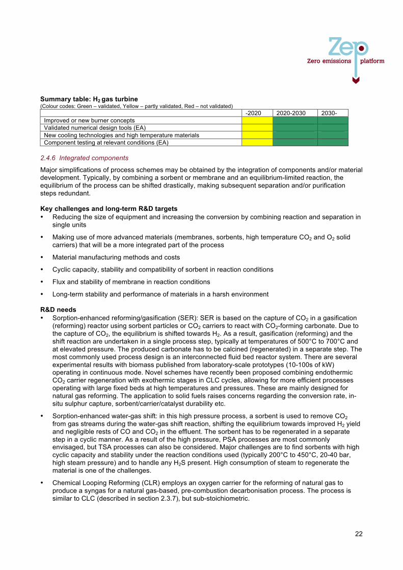
22
Summary table: H2 gas turbine (Colour codes: Green – validated, Yellow – partly validated, Red – not validated)
-2020 2020-2030 2030- Improved or new burner concepts Validated numerical design tools (EA) New cooling technologies and high temperature materials Component testing at relevant conditions (EA)
2.4.6 Integrated components
Major simplifications of process schemes may be obtained by the integration of components and/or material development. Typically, by combining a sorbent or membrane and an equilibrium-limited reaction, the equilibrium of the process can be shifted drastically, making subsequent separation and/or purification steps redundant. Key challenges and long-term R&D targets • Reducing the size of equipment and increasing the conversion by combining reaction and separation in
single units
• Making use of more advanced materials (membranes, sorbents, high temperature CO2 and O2 solid carriers) that will be a more integrated part of the process
• Material manufacturing methods and costs
• Cyclic capacity, stability and compatibility of sorbent in reaction conditions
• Flux and stability of membrane in reaction conditions
• Long-term stability and performance of materials in a harsh environment R&D needs • Sorption-enhanced reforming/gasification (SER): SER is based on the capture of CO2 in a gasification
(reforming) reactor using sorbent particles or CO2 carriers to react with CO2-forming carbonate. Due to the capture of CO2, the equilibrium is shifted towards H2. As a result, gasification (reforming) and the shift reaction are undertaken in a single process step, typically at temperatures of 500°C to 700°C and at elevated pressure. The produced carbonate has to be calcined (regenerated) in a separate step. The most commonly used process design is an interconnected fluid bed reactor system. There are several experimental results with biomass published from laboratory-scale prototypes (10-100s of kW) operating in continuous mode. Novel schemes have recently been proposed combining endothermic CO2 carrier regeneration with exothermic stages in CLC cycles, allowing for more efficient processes operating with large fixed beds at high temperatures and pressures. These are mainly designed for natural gas reforming. The application to solid fuels raises concerns regarding the conversion rate, in-situ sulphur capture, sorbent/carrier/catalyst durability etc.
• Sorption-enhanced water-gas shift: in this high pressure process, a sorbent is used to remove CO2 from gas streams during the water-gas shift reaction, shifting the equilibrium towards improved H2 yield and negligible rests of CO and CO2 in the effluent. The sorbent has to be regenerated in a separate step in a cyclic manner. As a result of the high pressure, PSA processes are most commonly envisaged, but TSA processes can also be considered. Major challenges are to find sorbents with high cyclic capacity and stability under the reaction conditions used (typically 200°C to 450°C, 20-40 bar, high steam pressure) and to handle any H2S present. High consumption of steam to regenerate the material is one of the challenges.
• Chemical Looping Reforming (CLR) employs an oxygen carrier for the reforming of natural gas to produce a syngas for a natural gas-based, pre-combustion decarbonisation process. The process is similar to CLC (described in section 2.3.7), but sub-stoichiometric.
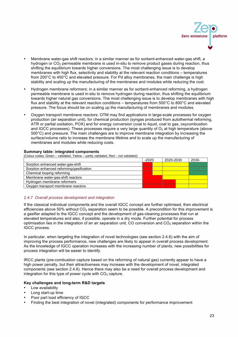
23
• Membrane water-gas shift reactors: in a similar manner as for sorbent-enhanced water-gas shift, a hydrogen or CO2 permeable membrane is used in-situ to remove product gases during reaction, thus shifting the equilibrium towards higher conversions. The most challenging issue is to develop membranes with high flux, selectivity and stability at the relevant reaction conditions – temperatures from 200°C to 450°C and elevated pressure. For Pd alloy membranes, the main challenge is high stability and scaling up the manufacturing of the membranes and modules while reducing the cost.
• Hydrogen membrane reformers: in a similar manner as for sorbent-enhanced reforming, a hydrogen permeable membrane is used in-situ to remove hydrogen during reaction, thus shifting the equilibrium towards higher natural gas conversions. The most challenging issue is to develop membranes with high flux and stability at the relevant reaction conditions – temperatures from 500°C to 800°C and elevated pressure. The focus should be on scaling up the manufacturing of membranes and modules.
• Oxygen transport membrane reactors: OTM may find applications in large-scale processes for oxygen production (air separation unit), for chemical production (syngas produced from autothermal reforming, ATR or partial oxidation, POX) and for energy conversion (coal to liquid, coal to gas, oxycombustion and IGCC processes). These processes require a very large quantity of O2 at high temperature (above 500°C) and pressure. The main challenges are to improve membrane integration by increasing the surface/volume ratio to increase the membrane lifetime and to scale up the manufacturing of membranes and modules while reducing costs.
Summary table: integrated components (Colour codes: Green – validated, Yellow – partly validated, Red – not validated)
-2020 2020-2030 2030- Sorption enhanced water-gas-shift Sorption enhanced reforming/gasification Chemical looping reforming Membrane water-gas-shift reactors Hydrogen membrane reformers Oxygen transport membrane reactors
2.4.7 Overall process development and integration
If the classical individual components and the overall IGCC concept are further optimised, then electrical efficiencies above 50% without CO2 separation seem to be possible. A precondition for this improvement is a gasifier adapted to the IGCC concept and the development of gas-cleaning processes that run at elevated temperatures and also, if possible, operate in a dry mode. Further potential for process optimisation lies in the integration of an air separation unit, CO conversion and CO2 separation within the IGCC process. In particular, when targeting the integration of novel technologies (see section 2.4.6) with the aim of improving the process performance, new challenges are likely to appear in overall process development. As the knowledge of IGCC operation increases with the increasing number of plants, new possibilities for process integration will be easier to identify. IRCC plants (pre-combustion capture based on the reforming of natural gas) currently appear to have a high power penalty, but their attractiveness may increase with the development of novel, integrated components (see section 2.4.6). Hence there may also be a need for overall process development and integration for this type of power cycle with CO2 capture. Key challenges and long-term R&D targets • Low availability • Long start-up time • Poor part load efficiency of IGCC • Finding the best integration of novel (integrated) components for performance improvement
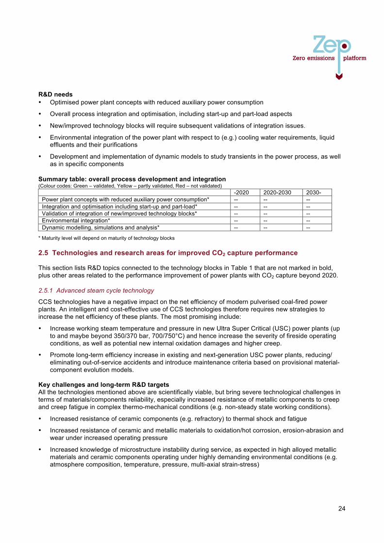
24
R&D needs • Optimised power plant concepts with reduced auxiliary power consumption
• Overall process integration and optimisation, including start-up and part-load aspects
• New/improved technology blocks will require subsequent validations of integration issues.
• Environmental integration of the power plant with respect to (e.g.) cooling water requirements, liquid effluents and their purifications
• Development and implementation of dynamic models to study transients in the power process, as well as in specific components
Summary table: overall process development and integration (Colour codes: Green – validated, Yellow – partly validated, Red – not validated)
-2020 2020-2030 2030- Power plant concepts with reduced auxiliary power consumption* -- -- -- Integration and optimisation including start-up and part-load* -- -- -- Validation of integration of new/improved technology blocks* -- -- -- Environmental integration* -- -- -- Dynamic modelling, simulations and analysis* -- -- --
* Maturity level will depend on maturity of technology blocks
2.5 Technologies and research areas for improved CO2 capture performance This section lists R&D topics connected to the technology blocks in Table 1 that are not marked in bold, plus other areas related to the performance improvement of power plants with CO2 capture beyond 2020.
2.5.1 Advanced steam cycle technology
CCS technologies have a negative impact on the net efficiency of modern pulverised coal-fired power plants. An intelligent and cost-effective use of CCS technologies therefore requires new strategies to increase the net efficiency of these plants. The most promising include:
• Increase working steam temperature and pressure in new Ultra Super Critical (USC) power plants (up to and maybe beyond 350/370 bar, 700/750°C) and hence increase the severity of fireside operating conditions, as well as potential new internal oxidation damages and higher creep.
• Promote long-term efficiency increase in existing and next-generation USC power plants, reducing/ eliminating out-of-service accidents and introduce maintenance criteria based on provisional material-component evolution models.
Key challenges and long-term R&D targets All the technologies mentioned above are scientifically viable, but bring severe technological challenges in terms of materials/components reliability, especially increased resistance of metallic components to creep and creep fatigue in complex thermo-mechanical conditions (e.g. non-steady state working conditions).
• Increased resistance of ceramic components (e.g. refractory) to thermal shock and fatigue
• Increased resistance of ceramic and metallic materials to oxidation/hot corrosion, erosion-abrasion and wear under increased operating pressure
• Increased knowledge of microstructure instability during service, as expected in high alloyed metallic materials and ceramic components operating under highly demanding environmental conditions (e.g. atmosphere composition, temperature, pressure, multi-axial strain-stress)
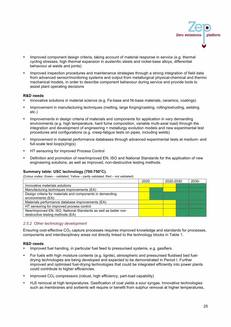
25
• Improved component design criteria, taking account of material response in service (e.g. thermal cycling stresses, high thermal expansion in austenitic steels and nickel-base alloys, differential behaviour at welds and joints)
• Improved inspection procedures and maintenance strategies through a strong integration of field data from advanced sensor/monitoring systems and output from metallurgical physical-chemical and thermo mechanical models, in order to describe component behaviour during service and provide tools to assist plant operating decisions
R&D needs • Innovative solutions in material science (e.g. Fe-base and Ni-base materials, ceramics, coatings)
• Improvement in manufacturing techniques (melting, large forging/casting, rolling/extruding, welding etc.)
• Improvements in design criteria of materials and components for application in very demanding environments (e.g. high temperature, hard fume composition, variable multi-axial load) through the integration and development of engineering + metallurgy evolution models and new experimental test procedures and configurations (e.g. creep-fatigue tests on pipes, including welds)
• Improvement in material performance databases through advanced experimental tests at medium- and full-scale test loop(s)/rig(s)
• HT sensoring for improved Process Control
• Definition and promotion of new/improved EN, ISO and National Standards for the application of new engineering solutions, as well as improved, non-destructive testing methods.
Summary table: USC technology (700-750°C). (Colour codes: Green – validated, Yellow – partly validated, Red – not validated)
-2020 2020-2030 2030- Innovative materials solutions Manufacturing techniques improvements (EA) Design criteria for materials and components in demanding environments (EA)
Materials performance database improvements (EA) HT sensoring for improved process control New/improved EN, ISO, National Standards as well as better non destructive testing methods (EA)
2.5.2 Other technology development
Ensuring cost-effective CO2 capture processes requires improved knowledge and standards for processes, components and interdisciplinary areas not directly linked to the technology blocks in Table 1. R&D needs • Improved fuel handing, in particular fuel feed to pressurised systems, e.g. gasifiers.
• For fuels with high moisture contents (e.g. lignite), atmospheric and pressurised fluidised bed fuel-drying technologies are being developed and expected to be demonstrated in Period I. Further improved and optimised fuel-drying technologies that could be integrated efficiently into power plants could contribute to higher efficiencies.
• Improved CO2 compressors (robust, high efficiency, part-load capability)
• H2S removal at high temperatures. Gasification of coal yields a sour syngas. Innovative technologies such as membranes and sorbents will require or benefit from sulphur removal at higher temperatures,
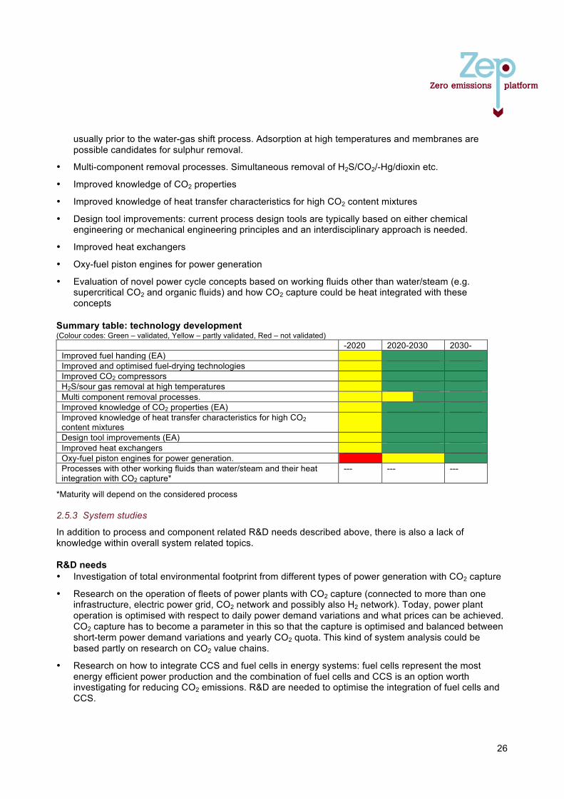
26
usually prior to the water-gas shift process. Adsorption at high temperatures and membranes are possible candidates for sulphur removal.
• Multi-component removal processes. Simultaneous removal of H2S/CO2/-Hg/dioxin etc.
• Improved knowledge of CO2 properties
• Improved knowledge of heat transfer characteristics for high CO2 content mixtures
• Design tool improvements: current process design tools are typically based on either chemical engineering or mechanical engineering principles and an interdisciplinary approach is needed.
• Improved heat exchangers
• Oxy-fuel piston engines for power generation
• Evaluation of novel power cycle concepts based on working fluids other than water/steam (e.g. supercritical CO2 and organic fluids) and how CO2 capture could be heat integrated with these concepts
Summary table: technology development (Colour codes: Green – validated, Yellow – partly validated, Red – not validated)
-2020 2020-2030 2030- Improved fuel handing (EA) Improved and optimised fuel-drying technologies Improved CO2 compressors H2S/sour gas removal at high temperatures Multi component removal processes. Improved knowledge of CO2 properties (EA) Improved knowledge of heat transfer characteristics for high CO2 content mixtures
Design tool improvements (EA) Improved heat exchangers Oxy-fuel piston engines for power generation. Processes with other working fluids than water/steam and their heat integration with CO2 capture*
--- --- ---
*Maturity will depend on the considered process 2.5.3 System studies
In addition to process and component related R&D needs described above, there is also a lack of knowledge within overall system related topics. R&D needs • Investigation of total environmental footprint from different types of power generation with CO2 capture
• Research on the operation of fleets of power plants with CO2 capture (connected to more than one infrastructure, electric power grid, CO2 network and possibly also H2 network). Today, power plant operation is optimised with respect to daily power demand variations and what prices can be achieved. CO2 capture has to become a parameter in this so that the capture is optimised and balanced between short-term power demand variations and yearly CO2 quota. This kind of system analysis could be based partly on research on CO2 value chains.
• Research on how to integrate CCS and fuel cells in energy systems: fuel cells represent the most energy efficient power production and the combination of fuel cells and CCS is an option worth investigating for reducing CO2 emissions. R&D are needed to optimise the integration of fuel cells and CCS.
27
• Studies on large- vs. small-scale CCS applications: from a long-term perspective, small-scale CCS could be commercially viable. Small-scale power production with small-scale CCS could be a possibility for green power production for all small villages in developing countries that do not have electricity today. Studies are needed to compare the technological and economic aspects of small- and large-scale CCS. Key challenges to be addressed are small-scale transport and storage of CO2.
• A research framework that enables tight integration between technology development on different scales and research areas, e.g. solvent-capture process-power process and membrane-membrane reactor-power process. The purpose of such R&D should be to obtain good design targets for solvents or materials and the best possible integration in a dedicated power process.
2.6 CO2 capture from power plants This section provides general recommendations on how to continue research on CO2 capture from power plants, as well as recommendations specific to each capture route. For the latter, a qualitative analysis was made of how the R&D topics described for the three different capture routes in sections 2.2-2.4 would affect the decision-making parameters in Table 2. For each R&D topic, it was assessed whether a success in research would result in a significantly positive or negative impact on any of the seven decision-making parameters, or have no significant impact. The qualitative results obtained were then analysed together with the information in the summary tables in sections 2.2-2.4. The results are presented below following the general recommendations. 2.6.1 General recommendations
Overall energy system studies are needed of power plants with CO2 capture operating as an integral part of energy systems with a high share of renewables. This means studying the interactions with solar and wind power – which must be combined with power plants with a high capability to follow load demands in the power grid – as well as CO2 capture from biofuels (Bio-CCS). Such studies should also cover CO2 transport and storage, and recognise the importance of power plant availability and operability. Depending on whether power plants with CCS are intended for base-load operation or as load followers, there will be differences in process design which need further attention. The future development of the electric power market will determine whether there will be any need for base-load power plants. There is a general recommendation to undertake research on novel – potentially ground-breaking – technologies which could radically improve the performance of CCS, if such technologies emerge. Overall power process development and investigations into the integration of novel CO2 capture related technologies into power processes and other industrial processes will continue to be important as capture technologies evolve. Highly efficient retrofittable CO2 capture solutions should be supported in order to address the urgent issue of locked-in carbon, i.e. CO2 emissions from newly-built fossil fuel power plants without CO2 capture. Ultra Super Critical (USC) steam technology development is highly important for increasing the efficiency of coal-based post-combustion and oxy-fuel technologies. Likewise, the development of advanced gas turbines for achieving higher turbine temperatures is important for natural gas-fired plants and IGCC. Pilot-scale testing is key to advancing technologies such as novel solvents, sorbents, membranes and CLC on the road to large-scale demonstration. A prerequisite for pilot testing of any technology is that promising performance has been verified both experimentally at lab scale and in studies of full-scale power plant performance. As a follow-up to successful pilot scale testing, an estimation of the potential when scaling up to demonstration- and/or full scale is required. Finally, it should be noted that the weighting factors assigned to the investment decision-making parameters in Table 2 also provide guidance for R&D on CO2 capture-related technologies. In particular, it
28
may be observed that there is little knowledge on the availability and operability of many technologies. As they become more mature and show promising performance both technically and economically, it is therefore important to undertake such analyses. 2.6.2 Post-combustion capture technologies
There is an overall recommendation to undertake research on post-combustion capture technologies for coal and other solid fuels, as well as natural gas. Both types of fuels must be able to respond to load changes in the power system due to a high share of renewables such as solar and wind power. Natural gas- fired power must be able to respond more rapidly to load change requirements than coal. R&D on CO2 enrichment in flue gas through recycling part of the gas turbine exhaust (often referred to as exhaust gas recirculation, EGR) should be undertaken in order to increase the efficiency of post-combustion capture from natural gas. Impact on CAPEX and OPEX is estimated to be positive, although a negative impact on power plant operability from the gas turbine is possible. That said, the natural gas combined cycle already has a very good operability, so some reduction should be acceptable in this case. Post-combustion capture power plants are a commercially available technology. It is a fact that commercial amine-based liquid solvents are on the market and that large-scale CO2 capture units are being built for commercial power plants. However, there is a potential for improvement, requiring further R&D on next- generation technologies, as described below. R&D on improved liquid solvents based on current commercial technologies, but with reduced energy penalty, should continue. R&D on novel liquid solvents, with a potential to significantly reduce the energy penalty should also be pursued. Examples include (but are not limited to) dual phase liquids, ionic liquids, precipitating solvents, as well as enzymes for catalysing CO2 absorption/desorption. Energy and cost- efficient capture processes that utilise improved and novel solvents must also be developed. R&D on solid sorbents should continue since there could be a positive effect on process efficiency compared to (current) liquid solvents and there could also be a positive impact on HSE. The operability and availability of power plants using solid sorbents for CO2 capture, compared to liquid solvents, should be assessed. There are possible synergies between calcium looping (which is the most mature example of solid sorbent technology) and CO2 capture in the cement industry that calls for further research. HSE is the main concern for current solvents and successful R&D on improved/novel solvents, sorbents or membranes is expected to improve the HSE of post-combustion capture, compared to current technology. There is little support within ZEP to continue research on hydrates as a post-combustion capture technology (particularly due to the estimated low maturity), or pursue anti-sublimation (i.e. freeze-out of CO2
11). However, there may be industrial applications for the latter. Recommendations for further R&D in these areas, when related to power plants, should be well-founded to be pursued and there may be advantages that have been omitted by ZEP. This report does not include any integrated components for post-combustion technologies (section 4.1). However, hybrid technologies, or combinations of technologies, may have been omitted that will prove to have a positive impact on one or several of the investment decision-making parameters, e.g. a combination of first applying CO2 membranes for CO2 enrichment of the flue gas, followed by liquefaction of CO2 to separate it from other exhaust gas components; and possibly other innovative concepts that are either entirely new or combine known technologies in novel ways.
11 Not to be confounded with low-temperature capture in the pre-combustion capture route which is based on CO2 liquefaction technology
29
2.6.3 Oxy-fuel technologies
The overall recommendation is to pursue R&D for oxy-fuel combustion: much has been undertaken on oxy-fuel for coal to prove that the technology is feasible and can become competitive, but efforts are still needed to make the technology marketable and economical – in particular, system-wide optimisation. However, it should be noted that large demonstrations (100s of MWth) of the entire oxy-fuel and capture route for coal have been planned, including completed FEED studies, and the technology is estimated to become commercially viable as a result. This should be supported by continued validations and R&D as there is also the potential for improvements, as described below. Advanced (more efficient) and flexible cryogenic air separating unit R&D should be pursued in order to improve oxy-fuel power plant efficiency and operability. Oxygen-separating membranes and solid sorbents are generally expected to have a positive impact on process efficiency, but a negative impact on operability and possibly also availability of the oxy-fuel plant. Time to commercialisation is estimated to be longer for membranes than adsorbents, but the overall estimate is that when realised, membranes will prove to be the preferred alternative to sorbents for efficient oxygen separation in the longer term. The development of most improved oxygen separation methods, including the advanced cryogenic ASU, is estimated to have a small negative impact on power plant CAPEX, which should be balanced by the estimated positive impact on efficiency. Pursuing the oxy-fuel capture route also means that R&D on oxy-fuel boilers and the overall oxy-fuel process should be continued. There are several opportunities for efficiency increase through boiler R&D, although some high-potential R&D topics (e.g. increased O2 concentration, pressurised oxy-fuel boilers and oxy-fuel boilers capable of switching to air-firing mode) could have a negative impact on availability and operability, requiring dedicated R&D. CO2 purification and compression is an important issue for oxy-fuel + coal and some R&D topics (e.g. improved CO2 compressor efficiency) are also relevant for oxy-fuel + natural gas. Oxygen transport membrane reactors12 for integration in oxy-fuel boilers are estimated to have a definitive positive impact on process efficiency, but OPEX and CAPEX, as well as operability and availability, are estimated to be worse than for oxy-fuel boilers with conventional cryogenic ASU. In the case of oxy-fuel combustion for gas turbine-based processes (natural gas-based power production), more R&D is needed before it can be determined whether this CO2 capture route is competitive when evaluated against the investment decision parameters in Table 2. At the current state of knowledge, no definitive conclusions can be drawn; it can only be observed that the technology has no obvious showstoppers, but there may be operability challenges that require dedicated R&D. Chemical Looping Combustion (CLC) is a technology that, in the long term, can offer power processes with the potential for high efficiency and potentially also high CO2 capture rate. For CLC, improved fuel conversion, new oxygen carrier materials, reactor design and power process integration are important R&D topics. Little research has been done on the operability and availability of CLC processes, but should be undertaken in order to evaluate whether they are acceptable in this respect. Pressurised reactors for coal and gas CLC could have significant efficiency advantages, but also face significant challenges and should be regarded as high risk/high gain R&D areas. 2.6.4 Pre-combustion technologies
The overall recommendation is that research related to the Integrated Gasification Combined Cycle (IGCC) should be pursued. IGCC, when implemented with modern technology, has the potential to produce power from coal at a higher efficiency than the conventional pulverised fuel combustion of coal, plus the ability to convert solid fuels of varying quality (including biomass) into electricity.
12 Oxygen membranes and oxygen membrane reactors are two slightly different types of technology. In the oxygen membrane reactor, an oxidation or combustion reactor takes place in the same compartment as the oxygen separation from air.
30
It should be noted that IGCC technology with CO2 capture is commercially available with both state-of-the-art ASU and existing gas turbines (which show a slight reduction in efficiency since they are manufactured for operation with natural gas). The main R&D needs for improving IGCC performance relate to improved ASU, improved gas turbine efficiency with high H2-content in the fuel gas and improvements in the syngas cleaning section (at high temperature). This will improve the efficiency of the IGCC plant beyond 2020 and therefore also reduce CO2 capture costs. As for oxy-fuel, advanced (more efficient) and flexible cryogenic ASU R&D should be pursued in order to improve power plant efficiency and operability. However, the integration and optimisation of air separation technologies is different for IGCC than for oxy-fuel. Oxygen-separating membranes and solid sorbents are generally estimated to have a positive impact on process efficiency, but a negative impact on operability and possibly also availability of the IGCC. Time to commercialisation is estimated to be longer for membranes than for adsorbents, but the overall estimate is that when realised, membranes will prove to be the preferred alternative to sorbents for efficient oxygen separation in the longer term. The development of most improved oxygen separation methods, including advanced cryogenic ASU, is estimated to have a small negative impact on power plant CAPEX, which should be balanced by a positive impact on efficiency. Improvements in gasifiers for IGCC should also be pursued, e.g. improved slag and fly ash removal, improved fuel conversion, reduction in the amount of gasification agent required and improved coal feeding. For H2 gas turbines, the recommendation is straightforward: as long as R&D is pursued on the IGCC capture route, R&D must also be pursued on efficient, low-emission hydrogen gas turbines. Once this has been realised, improvements will always be necessary to keep track of those in conventional gas turbines. Positive results are expected from further R&D on water-gas shift (WGS) reactors – in particular, the further development of shift catalysts (including sour shift catalysts) and improvements in WGS reactor design. As it concerns the separation of CO2 and H2 in the shifted syngas, it is noted that current commercial solvents for CO2 separation at conditions typical for IGCC have a rather low energy penalty. Nevertheless, R&D on alternative separation technologies (e.g. H2-separating membranes, sorbents and low-temperature separation of CO2, with a focus on availability and operability) should be supported for implementation in the longer term to enable further efficiency improvements. Integrated components for pre-combustion capture (see section 2.4.6) are generally estimated to have a positive impact on process efficiency and possibly also on CAPEX (due to a reduction in the number of process components), but with an estimated negative impact on availability and operability. It should be emphasised that more research could still be done to assess the impact of integrated components on all investment decision-making parameters. Technology development related to pre-combustion capture from power plants contains elements (in particular, separation technologies and integrated components) which may prove very useful for H2 production with CO2 capture in industrial applications. It is therefore recommended not to focus research on the Integrated Reforming Combined Cycle (IRCC) due to its anticipated poor operability (in particular load-following capacity) compared to a NGCC with post-combustion capture. Natural gas-based pre-combustion technologies should potentially focus on H2 production with CO2 capture.
31
Annex: Bio-CCS and CCS in industries beyond power This report covers R&D needs for CO2 capture in the power sector, primarily based on fossil fuels. However, the EU Energy Roadmap 2050 confirms that CCS combined with biomass can deliver "carbon negative" values, while the IEA underlines that CCS in energy-intensive industries must deliver half of the global emissions reductions required by 2050 from CCS.13 In general, all the CO2 capture technologies described in this report can have applications beyond fossil fuel-based power. Bio-CCS: the only large-scale technology that can remove CO2 from the atmosphere
In 2011, the European Biofuels Technology Platform (EBTP) and ZEP set up a joint taskforce (JTF) Bio-CCS to review the various technology routes for combining CCS with biomass conversion. This resulted in a landmark report14 that covers CCS with the production of biofuels, electricity/heat from biomass (both co-firing and 100% biomass combustion), as well as Bio-CCS options for energy-intensive industries. The report shows how several biofuel production routes offer a near-pure stream of CO2 as an integral part of their processes, opening the way for very low-cost CCS deployment where economies of scale can be applied, or where adjacent CO2 transport and storage infrastructure can be shared. Co-firing biomass with coal or lignite at moderate percentages (at least up to 10%) is also not expected to increase the costs of CCS deployment. (N.B. This refers to the cost of co-firing, not the cost of biomass relative to fossil fuels as this varies highly.) However, for higher co-firing rates and dedicated biomass combustion, higher investment costs and efficiency penalties may be expected. The composition of biomass fuels is variable, but they generally have a higher alkaline content than fossil fuels which can, for example, lead to ash deposition and corrosion when co-firing with fossil fuels in boilers. The report of the JTF Bio-CCS states that mode data and research is needed on these issues, as well as other potential technological challenges. Most of the CO2 capture R&D topics described in this report should be investigated from a biomass point of view and all three capture routes could, in principle, be adapted to biomass power production. Some emerging capture systems (in particular, those operating at high temperatures that can combine biomass gasification and/or combustion with CO2 sorption in a single step) could be especially suited to power plants with biomass and CCS. This includes both co-firing and 100% biomass applications in order to identify the most feasible technology options. Indeed, if optimised and cost-effective biomass production is achieved, some variants could be ready before 2030, at the latest (i.e. in Period II, as defined in section 2.1.1). It should also be assessed whether there is any transference of alkalines from the biofuel to the captured CO2 and if this could imply additional corrosion risks or other issues for CO2 transport and storage. Realising the significant potential for CCS in industries beyond power
According to the IEA, CCS represents the most important new technology option for reducing direct emissions in industry. Indeed, in some industries, such as steel and cement, it is the only means of achieving deep emission cuts, with the potential to mitigate 2-2.5 gigatonnes of CO2 per year globally by 2050.15 In Europe, several industries are already currently implementing CCS at pilot scale. In 2012, ZEP therefore created Working Group (WG) Other Industries in order to review technology synergies and options for CCS deployment in energy-industries and seek cooperation with representatives
13 IEA: www.iea.org/publications/freepublications/publication/name,38764,en.html 14 “Biomass with CO2 Capture and Storage (Bio-CCS) – The way forward for Europe”: www.zeroemissionsplatform.eu/library/publication/206-biomass-with-co2-capture-and-storage-bio-ccs- the-way-forward-for-europe.html 15 IEA Energy Technology Perspectives, 2012
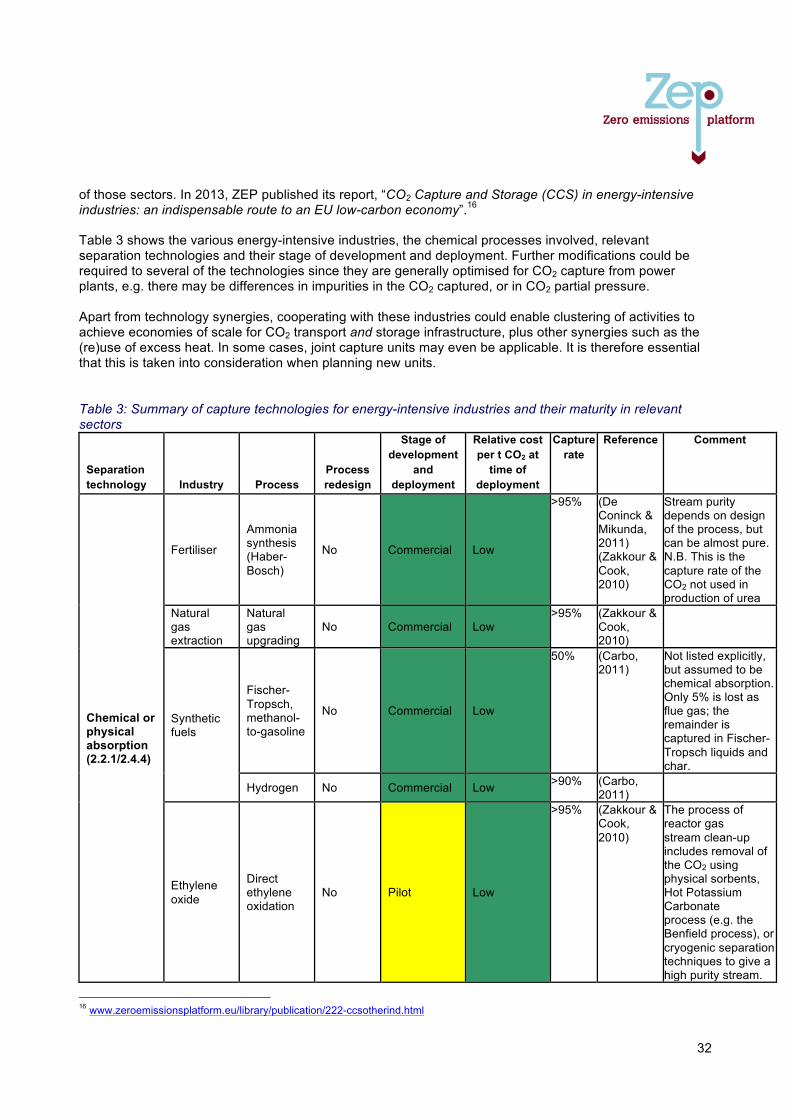
32
of those sectors. In 2013, ZEP published its report, “CO2 Capture and Storage (CCS) in energy-intensive industries: an indispensable route to an EU low-carbon economy”.16 Table 3 shows the various energy-intensive industries, the chemical processes involved, relevant separation technologies and their stage of development and deployment. Further modifications could be required to several of the technologies since they are generally optimised for CO2 capture from power plants, e.g. there may be differences in impurities in the CO2 captured, or in CO2 partial pressure. Apart from technology synergies, cooperating with these industries could enable clustering of activities to achieve economies of scale for CO2 transport and storage infrastructure, plus other synergies such as the (re)use of excess heat. In some cases, joint capture units may even be applicable. It is therefore essential that this is taken into consideration when planning new units.
Table 3: Summary of capture technologies for energy-intensive industries and their maturity in relevant sectors
Separation technology Industry Process
Process redesign
Stage of development
and deployment
Relative cost per t CO2 at
time of deployment
Capture rate
Reference Comment
Chemical or physical absorption (2.2.1/2.4.4)
Fertiliser
Ammonia synthesis (Haber-Bosch)
No Commercial Low
>95% (De Coninck & Mikunda, 2011) (Zakkour & Cook, 2010)
Stream purity depends on design of the process, but can be almost pure. N.B. This is the capture rate of the CO2 not used in production of urea
Natural gas extraction
Natural gas upgrading
No Commercial Low >95% (Zakkour &
Cook, 2010)
Synthetic fuels
Fischer-Tropsch, methanol-to-gasoline
No Commercial Low
50% (Carbo, 2011)
Not listed explicitly, but assumed to be chemical absorption. Only 5% is lost as flue gas; the remainder is captured in Fischer-Tropsch liquids and char.
Hydrogen No Commercial Low >90% (Carbo, 2011)
Ethylene oxide
Direct ethylene oxidation
No Pilot Low
>95% (Zakkour & Cook, 2010)
The process of reactor gas stream clean-up includes removal of the CO2 using physical sorbents, Hot Potassium Carbonate process (e.g. the Benfield process), or cryogenic separation techniques to give a high purity stream.
16 www.zeroemissionsplatform.eu/library/publication/222-ccsotherind.html
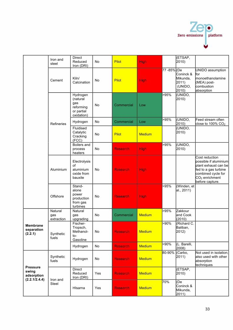
33
Iron and steel
Direct Reduced Iron (DRI)
No Pilot High (ETSAP,
2010)
Cement Kiln/ Calcination No Pilot High
77 -85% (De Coninck & Mikunda, 2011) (UNIDO, 2010)
UNIDO assumption for monoethanolamine (MEA) post-combustion absorption
Refineries
Hydrogen (natural gas reforming or partial oxidation)
No Commercial Low
>95% (UNIDO, 2010)
Hydrogen No Commercial Low >95% (UNIDO, 2010)
Feed stream often close to 100% CO2
Fluidised Catalytic Cracking (FCC)
No Pilot Medium
(UNIDO, 2010)
Boilers and process heaters
No Research High >95% (UNIDO,
2010)
Aluminium
Electrolysis of aluminium oxide from bauxite
No Research High
Cost reduction possible if aluminium plant exhaust can be fed to a gas turbine combined cycle for CO2 enrichment before capture.
Offshore
Stand-alone power production from gas turbines
No Research High
>95% (Winden, et al., 2011)
Membrane separation (2.2.1)
Natural gas extraction
Natural gas upgrading
No Commercial Medium >95% Zakkour
and Cook (2010)
Synthetic fuels
Fischer-Tropsch, Methanol-to-Gasoline
No Research Medium
>90% (Richard C. Baliban, 2012)
Hydrogen No Research Medium >90% (L. Barelli, 2008)
Pressure swing adsorption (2.2.1/2.4.4)
Synthetic fuels Hydrogen No Research Medium
80-90% (Carbo, 2011)
Not used in isolation; also used with other absorption techniques
Iron and Steel
Direct Reduced Iron (DRI)
Yes Research Medium (ETSAP,
2010)
HIsarna Yes Research Medium
70% (De Coninck & Mikunda, 2011)
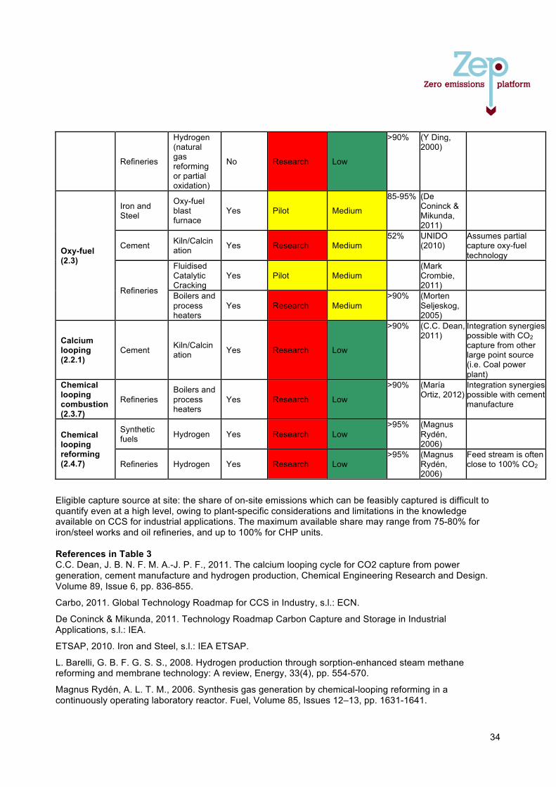
34
Refineries
Hydrogen (natural gas reforming or partial oxidation)
No Research Low
>90% (Y Ding, 2000)
Oxy-fuel (2.3)
Iron and Steel
Oxy-fuel blast furnace
Yes Pilot Medium
85-95% (De Coninck & Mikunda, 2011)
Cement Kiln/Calcination Yes Research Medium
52% UNIDO (2010)
Assumes partial capture oxy-fuel technology
Refineries
Fluidised Catalytic Cracking
Yes Pilot Medium (Mark
Crombie, 2011)
Boilers and process heaters
Yes Research Medium >90% (Morten
Seljeskog, 2005)
Calcium looping (2.2.1)
Cement Kiln/Calcination Yes Research Low
>90% (C.C. Dean, 2011)
Integration synergies possible with CO2 capture from other large point source (i.e. Coal power plant)
Chemical looping combustion (2.3.7)
Refineries Boilers and process heaters
Yes Research Low
>90% (María Ortiz, 2012)
Integration synergies possible with cement manufacture
Chemical looping reforming (2.4.7)
Synthetic fuels Hydrogen Yes Research Low
>95% (Magnus Rydén, 2006)
Refineries Hydrogen Yes Research Low >95% (Magnus
Rydén, 2006)
Feed stream is often close to 100% CO2
Eligible capture source at site: the share of on-site emissions which can be feasibly captured is difficult to quantify even at a high level, owing to plant-specific considerations and limitations in the knowledge available on CCS for industrial applications. The maximum available share may range from 75-80% for iron/steel works and oil refineries, and up to 100% for CHP units. References in Table 3 C.C. Dean, J. B. N. F. M. A.-J. P. F., 2011. The calcium looping cycle for CO2 capture from power generation, cement manufacture and hydrogen production, Chemical Engineering Research and Design. Volume 89, Issue 6, pp. 836-855.
Carbo, 2011. Global Technology Roadmap for CCS in Industry, s.l.: ECN.
De Coninck & Mikunda, 2011. Technology Roadmap Carbon Capture and Storage in Industrial Applications, s.l.: IEA.
ETSAP, 2010. Iron and Steel, s.l.: IEA ETSAP.
L. Barelli, G. B. F. G. S. S., 2008. Hydrogen production through sorption-enhanced steam methane reforming and membrane technology: A review, Energy, 33(4), pp. 554-570.
Magnus Rydén, A. L. T. M., 2006. Synthesis gas generation by chemical-looping reforming in a continuously operating laboratory reactor. Fuel, Volume 85, Issues 12–13, pp. 1631-1641.
María Ortiz, L. F. d. D., A. A.,. F. G.-L., P. G., J. A., 2012. Catalytic Activity of Ni-Based Oxygen-Carriers for Steam Methane Reforming in Chemical-Looping Processes. Energy & Fuels, p. 791–800.
Mark Crombie, S. I. I. M., 2011. CO2 capture project phase 3 — Demonstration phase. Energy Procedia, Volume 4, pp. 6104-6108.
Morten Seljeskog, M. D., 2005. Oxy-fuel retrofitting of heavy fuel oil fired refinery heaters, A lab scale experimental approach on heavy Fuel oil No 6. s.l., s.n.
Richard C. Baliban, J. A. E. V. W. C. A. F., 2012. Process synthesis of hybrid coal, biomass, and natural gas to liquids via Fischer–Tropsch synthesis, ZSM-5 catalytic conversion, methanol synthesis, methanol-to-gasoline, and methanol-to-olefins/distillate technologies. Chemical Engineering.
UNIDO, 2010. Carbon Capture and Storage in Industrial Applications: Technology Synthesis Report, s.l.: UNIDO.
Winden, et al., 2011. Offshore thermal power with CCS: an alternative to CO2 transportation, s.l.: University of Southampton instituted a research.
Y Ding, E. A., 2000. Adsorption-enhanced steam–methane reforming. Chemical Engineering Science, Volume 55, Issue 18, pp. 3929-3940.
Zakkour & Cook, 2010. CCS Roadmap for Industry: High-purity CO2 sources, s.l.: Carbon Counts.
September 2013 www.zeroemissionsplatform.eu

82
Allegato 4 - Carbon Sequestration Leadership Forum (CSLF) recognized projects and Task Forces on storage
Carbon'Sequestra.on'Leadership'Forum'(CSLF)'recognized'projects'and'
Task'Forces'on'storage
1"
Giuseppe"Girardi,"CSLF"–"ENEA"[email protected]
Technical'Group'Mee.ng,'Rome,'Italy'F'April'17,'2013
Technical'Group'Mee.ng,'Rome,'Italy'F'April'17,'2013
'''''ABOUT'THE'CSLF
! CSLF"is"a"MinisterialFlevel'interna.onal'climate'change'ini.a.ve'that"is"focused"on"the"development"of"improved"cost>effec@ve"CCS"technologies."
MISSION' ! to"facilitate"the"development"and"deployment"of"such"
technologies"via"collabora@ve"efforts"that"address"key"technical,"economic,"and"environmental"obstacles"
! to"promote"awareness"and"champion"legal,"regulatory,"financial,"and"ins@tu@onal"environments."
2"
ALLEGATO 4

Technical'Group'Mee.ng,'Rome,'Italy'F'April'17,'2013
CSLF'Projects CSLF"promotes"collabora@ve"research,"development,"and"demonstra@on"projects"that"exhibit:""
! Informa@on"exchange"and"networking"! Planning"and"road>mapping"! Facilita@on"of"collabora@on"! Research"and"development"! Demonstra@ons"
3"
39'projects'recognized:'27'ac.ve,'12'already'completed
"6"pilot"projects" 21"Large"Scale"or"Mul@faceted"
Ac.ve'and'Completed'CSLF'Recognized'Projects
ac@ve"projects"completed"projects"
4"
15"projects"
1"project"
4"projects"
2"projects"
1"project"
9"projects"
7"projects"
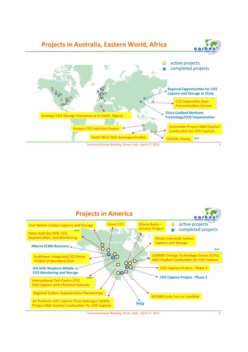
Technical'Group'Mee.ng,'Rome,'Italy'F'April'17,'2013
ac@ve"projects"completed"projects"
CarbonNet'Project'R&D'Oxyfuel'Combus.on'for'CO2'Capture"
South'West'Hub'Geosequestra.on"
Gorgon'CO2'Injec.on'Project'"
CO2$Separa*on$from PressurizedGas$Stream
China'Coalbed'Methane Technology/CO2'Sequestra.on"Geologic'CO2'Storage'Assurance'at'In'Salah,'Algeria"
CO2CRC'Otway"
Regional'Opportuni.es'for'CO2 Capture'and'Storage'in'China"
Projects'in'Australia,'Eastern'World,'Africa''
5"
PILOT
Technical'Group'Mee.ng,'Rome,'Italy'F'April'17,'2013
ac@ve"projects"completed"projects"
Frio"Air'Products'CO2'Capture'from'Hydrogen'Facility'Project'R&D'Oxyfuel'Combus.on'for'CO2'Capture"
SECARB'Early'Test'at'Cranfield"
CANMET$Energy$Technology$Centre$(CETC) R&D$Oxyfuel$Combus*on$for$CO2$Capture
CO2'Capture'Project'F'Phase'3'"
Illinois'Industrial'Carbon Capture'and'Storage"
CO2'Capture'Project'F'Phase'2"
Illinois'Basin'– Decatur'Project"
Regional'Carbon'Sequestra.on'Partnerships"
Fort'Nelson'Carbon'Capture'and'Storage"
Zama'Acid'Gas'EOR,'CO2 Sequestra.on,'and'Monitoring"
Alberta'ECBM'Recovery"
IEA'GHG'WeyburnFMidale CO2'Monitoring'and'Storage"
Quest'CCS"
SaskPower'Integrated'CCS'Demo 'Project'at'Boundary'Dam"
Interna*onal$Test$Centre$(ITC) CO2$Capture$with$Chemical$Solvents$
Projects'in'America
6"
7"projects"
9"projects"
PILOT
PILOT
PILOT
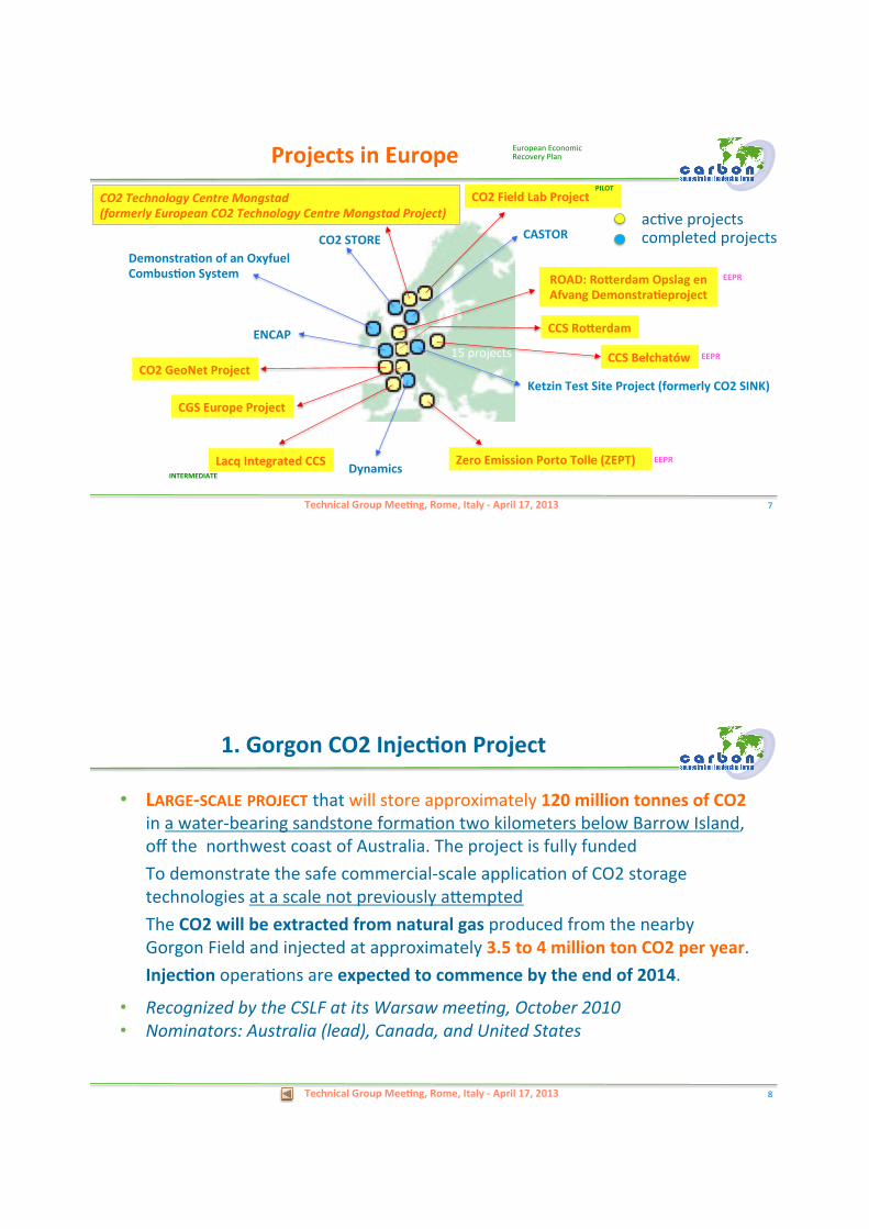
Technical'Group'Mee.ng,'Rome,'Italy'F'April'17,'2013
ac@ve"projects"completed"projects"
Zero'Emission'Porto'Tolle'(ZEPT)"Lacq'Integrated'CCS'" Dynamics"
CO2'Field'Lab'Project'''''''''''"CO2$Technology$Centre$Mongstad (formerly$European$CO2$Technology$Centre$Mongstad$Project)$
CO2'STORE"Demonstra.on'of'an'Oxyfuel Combus.on'System"
CASTOR"
ROAD:'Roberdam'Opslag'en Afvang'Demonstra.eproject
Ketzin'Test'Site'Project'(formerly'CO2'SINK)"
CCS'Bełchatów"
CCS'Roberdam"
CO2'GeoNet'Project'"
CGS'Europe'Project'"
ENCAP"
Projects'in'Europe
7"
15"projects"
EEPR"
European"Economic"Recovery"Plan""
EEPR"
EEPR"
PILOT
INTERMEDIATE"
Technical'Group'Mee.ng,'Rome,'Italy'F'April'17,'2013
• LARGEFSCALE'PROJECT'that"will"store"approximately"120'million'tonnes'of'CO2'in"a"water>bearing"sandstone"forma@on"two"kilometers"below"Barrow"Island,"off"the""northwest"coast"of"Australia."The"project"is"fully"funded""To"demonstrate"the"safe"commercial>scale"applica@on"of"CO2"storage"technologies"at"a"scale"not"previously"aZempted""The"CO2'will'be'extracted'from'natural'gas'produced"from"the"nearby"Gorgon"Field"and"injected"at"approximately"3.5'to'4'million'ton'CO2'per'year.""Injec.on'opera@ons"are"expected'to'commence'by'the'end'of'2014."
• Recognized!by!the!CSLF!at!its!Warsaw!mee>ng,!October!2010""• Nominators:!Australia!(lead),!Canada,!and!United!States"
1.'Gorgon'CO2'Injec.on'Project
8"
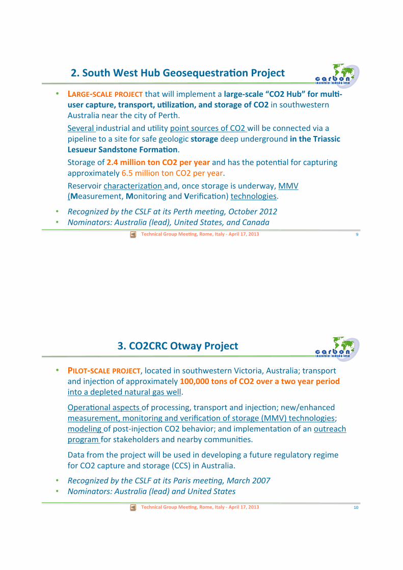
Technical'Group'Mee.ng,'Rome,'Italy'F'April'17,'2013
• LARGEFSCALE'PROJECT'that"will"implement"a"largeFscale'“CO2'Hub”'for'mul.Fuser'capture,'transport,'u.liza.on,'and'storage'of'CO2'in"southwestern"Australia"near"the"city"of"Perth.""Several"industrial"and"u@lity"point"sources"of"CO2"will"be"connected"via"a"pipeline"to"a"site"for"safe"geologic"storage'deep"underground"in'the'Triassic'Lesueur'Sandstone'Forma.on."""Storage"of"2.4'million'ton'CO2'per'year'and"has"the"poten@al"for"capturing"approximately"6.5"million"ton"CO2"per"year.""Reservoir"characteriza@on"and,"once"storage"is"underway,"MMV"(Measurement,"Monitoring"and"Verifica@on)"technologies."
• Recognized!by!the!CSLF!at!its!Perth!mee>ng,!October!2012 • Nominators:!Australia!(lead),!United!States,!and!Canada"
2.'South'West'Hub'Geosequestra.on'Project
9"
Technical'Group'Mee.ng,'Rome,'Italy'F'April'17,'2013
• PILOTFSCALE'PROJECT,"located"in"southwestern"Victoria,"Australia;"transport"and"injec@on"of"approximately"100,000'tons'of'CO2'over'a'two'year'period'into"a"depleted"natural"gas"well.""
"Opera@onal"aspects"of"processing,"transport"and"injec@on;"new/enhanced"measurement,"monitoring"and"verifica@on"of"storage"(MMV)"technologies;"modeling"of"post>injec@on"CO2"behavior;"and"implementa@on"of"an"outreach"program"for"stakeholders"and"nearby"communi@es.""
"Data"from"the"project"will"be"used"in"developing"a"future"regulatory"regime"for"CO2"capture"and"storage"(CCS)"in"Australia."
• Recognized!by!the!CSLF!at!its!Paris!mee>ng,!March!2007 • Nominators:!Australia!(lead)!and!United!States"
3.'CO2CRC'Otway'Project
10"
Technical'Group'Mee.ng,'Rome,'Italy'F'April'17,'2013
• LARGEFSCALE'PROJECT'that"will"implement"a"largeFscale'mul.Fuser'CO2"capture,"transport,"and"storage'network'in"southeastern"Australia"in"the"Latrobe"Valley.""Mul@ple"industrial"and"u@lity"point"sources"of"CO2"will"be"connected"via"a"pipeline"to"a"site"where"the"CO2"can"be"stored"in"depleted'oil'and'gas'fields'in'the'offshore'Gippsland'Basin.""Storage"of"approximately"1'to'5'million'ton'CO2'per'year,"with"the"poten@al"to"increase"capacity"significantly"over"@me.""The"project"will"also"include"reservoir"characteriza@on"and,"once"storage"is"underway,"measurement,"monitoring"and"verifica@on"(MMV)"technologies."
• Recognized!by!the!CSLF!at!its!Perth!mee>ng,!October!2012 • Nominators:!Australia!(lead)!and!United!States""
4.'CarbonNet'Project
11"
Technical'Group'Mee.ng,'Rome,'Italy'F'April'17,'2013
• PILOTFSCALE'PROJECT'successfully"demonstrated"that"coal"seams"in"the"anthraci@c"coals"of"Shanxi"Province"of"China"are"permeable"and"stable"enough"to"absorb"CO2"and"enhance"methane"produc@on,"leading"to"a"clean"energy"source"for"China.""The"project"evaluated'reservoir'proper.es'of"selected"coal"seams"of"the"Qinshui"Basin"of"eastern"China"and"carried"out"field"tes@ng"at"rela@vely"low"CO2"injec@on"rates."""The"project"recommenda@on"was"to"proceed"to"full"scale"pilot"test"at"south"Qinshui,"as"the"prospect"in"other"coal"basins"in"China"is"good."
• Recognized!by!the!CSLF!at!its!Berlin!mee>ng,!September!2005 • Nominators:!Canada!(lead),!United!States,!and!China""
5.'China'Coalbed'Methane'Technology CO2'Sequestra.on
12"
Technical'Group'Mee.ng,'Rome,'Italy'F'April'17,'2013
• CHARACTERIZATION'OF'TECHNICAL'AND'ECONOMIC'POTENTIAL'OF'CCS'IN'CHINA"">"key"characteris@cs"of"different""large"anthropogenic"CO2"sources"">"candidate"geologic"storage"forma@ons,"and"to"develop"es@mates"of"geologic"CO2"storage"capaci@es"in"China.""The"project"found"2,300'gigatons'of'poten.al'CO2'storage'capacity'in'onshore'Chinese'basins,"significantly"more"than"previous"es@mates.""The"heavily"developed"coastal"areas"of"the"East"and"South"Central"regions"appear"to"have"less"access"to"large"quan@@es"of"onshore"storage"capacity"than"many"of"the"inland"regions.""Therefore,"China’s"economic"growth"with"coal"can"con@nue."
• Recognized!by!the!CSLF!at!its!Berlin!mee>ng,!September!2005 • Nominators:!United!States!(lead)!and!China""
6.'Regional'Opportuni.es'for' CO2'Capture'and'Storage'in'China'
13"
Technical'Group'Mee.ng,'Rome,'Italy'F'April'17,'2013
• SMALLFSCALE'PROJECT'will"evaluate"processes"and"economics"for"CO2'separa.on'from'pressurized'gas'streams."""To"test"new"gas"separa@on"membranes,"ini@ally"at"atmospheric"pressure.""To"improve"the"performance"of"the"membranes"for"CO2"removal"from"the"fuel"gas"product"of"coal"gasifica@on"and"other"gas"streams"under"high"pressure.""
• Recognized!by!the!CSLF!at!its!Melbourne!mee>ng,!September!2004 • Nominators:!Japan!(lead)!and!United!States"
7.'CO2'Separa.on'from'Pressurized'Gas'Stream
14"
Technical'Group'Mee.ng,'Rome,'Italy'F'April'17,'2013
• MULTIFACETED'PROJECT'To"develop"technologies,"techniques"and"management"systems"required"to"cost>effec@vely"demonstrate,"safe,"secure,"and"verifiable"CO2'storage'in'conjunc.on'with'commercial'natural'gas'produc.on."""To"develop"a"detailed"dataset"on"the"performance'of"CO2"storage;"provide"a"field>scale"example"on"the"verifica@on"and"regula@on"of"geologic"storage"systems;"test"technology"op@ons"for"the"early"detec@on"of"low>level"seepage"of"CO2"out"of"primary"containment;"evaluate"monitoring'op@ons"and"develop"guidelines"for"an"appropriate"and"cost>effec@ve,"long>term"monitoring"methodology;"and"quan@fy"the"interac.on'of'CO2'reFinjec.on'and'hydrocarbon'produc.on'for'longFterm'storage'in'oil'and'gas'fields.""
• Recognized!by!the!CSLF!at!its!Berlin!mee>ng,!September!2005 • Nominators:!United!Kingdom!(lead)!and!Norway"
8.'Geologic'CO2'Storage'Assurance'at' In'Salah,'Algeria
15"
Technical'Group'Mee.ng,'Rome,'Italy'F'April'17,'2013
• LARGEFSCALE,'FULLY'INTEGRATED'PROJECT,"located"at"Fort"Saskatchewan,"Alberta,"Canada,"with"integrated'capture,'transporta.on,'storage,'and'monitoring,"which"will"capture"and"store"up"to"1.2'million'ton'CO2'per'year'from"an"oil"sands"upgrading"unit.""The"CO2"will"be"transported"via"pipeline"and"stored"in"a"deep"saline"aquifer"in"the"Western"Sedimentary"Basin"in"Alberta,"Canada.""""Large>scale"deployment"of"CCS"technologies"and"methodologies,"including"a"comprehensive"measurement,"monitoring"and"verifica@on"(MMV)"program."
• Recognized!by!the!CSLF!at!its!Warsaw!mee>ng,!October!2010"• Nominators:!Canada!(lead),!United!Kingdom,!and!United!States"
9.'Quest'CCS'Project
16"
Technical'Group'Mee.ng,'Rome,'Italy'F'April'17,'2013
• LARGEFSCALE'PROJECT'in"northeastern"Bri@sh"Columbia,"Canada" 2'million'tonnes'per'year'CO2'emissions"from"a"large"natural"gas>processing"plant"will"be"stored"into"deep"saline"forma@ons"of"the"Western"Canadian"Sedimentary"Basin"(WCSB).""Technical"and"economic"feasibility"of"using"brine>saturated"carbonate"forma@ons"for"large>scale"CO2"injec@on""demonstrate"that"robust"monitoring,"verifica@on,"and"accoun@ng"(MVA)"of"a"brine>saturated"CO2"sequestra@on"project"can"be"conducted"cost>effec@vely."""regula@ons"and"MVA"technologies"for"future"large>scale"CO2"injec@on."
• Recognized!by!the!CSLF!at!its!London!mee>ng,!October!2009 • Nominators:!Canada!(lead)!and!United!States"
10.'Fort'Nelson'Carbon'Capture'and'Storage'Project
17"
Technical'Group'Mee.ng,'Rome,'Italy'F'April'17,'2013
• PILOTFSCALE'PROJECT''U@liza@on"of"acid"gas"(70%"CO2"and"30%"hydrogen"sulfide)"derived"from"natural"gas"extrac@on"for"enhanced"oil"recovery.""Acid"gas"injec@on"was"ini@ated"in"December"2006"and"will"result"in"sequestra@on"of"about"25,000'ton'CO2'per'year ">"To"predict,"monitor,"and"evaluate"the"fate"of"the"injected"acid"gas;"">"to"determine"the"effect"of"hydrogen"sulfide"on"CO2"sequestra@on;"">"to"develop"a"“best"prac@ces"manual”"for"measurement,"monitoring,"and""""""verifica@on"(MMV)"of"acid"gas"storage."
• Recognized!by!the!CSLF!at!its!Paris!mee>ng,!March!2007 • Nominators:!Canada!(lead)!and!United!States"
11.'Zama'Acid'Gas'EOR,' CO2'Sequestra.on,'and'Monitoring
18"
Technical'Group'Mee.ng,'Rome,'Italy'F'April'17,'2013
12.'Alberta'Enhanced'CoalFBed'Methane'Recovery • PILOTFSCALE'PROJECT,"located"in"Alberta,"Canada,"aimed"at"demonstra@ng,"
from"both"economic"and"environmental"criteria,"the"overall"feasibility"of"CBM'and"simultaneous"CO2'storage'in'deep'unmineable'coal'seams."""To"determine"baseline"produc@on"of"CBM"from"coals;"determine"the"effect"of"CO2"injec@on"and"storage"on"CBM"produc@on;"assess"economics;"and"monitor"and"trace"the"path"of"CO2"movement"by"geochemical"and"geophysical"methods."""All"tes@ng"undertaken"was"successful."
• Recognized!by!the!CSLF!at!its!Melbourne!mee>ng,!September!2004 • Nominators:!Canada!(lead),!United!States,!and!United!Kingdom"
19"
Technical'Group'Mee.ng,'Rome,'Italy'F'April'17,'2013
• LARGEFSCALE'PROJECT',"located"in"the"southeastern"corner"of"Saskatchewan"Province"in"Canada,"which"will"be"the"first"applica@on"of"full'stream'CO2'recovery'from'flue'gas'of'a'139'megawab'coalFfueled'power'plant."Post>combus@on"CO2"capture"retrofit"on"a"commercial"power"plant."Capture"of"approximately"1million'tonn'CO2'per'year,"which"will"be"sold"to"oil"producers"for"enhanced"oil"recovery"(EOR)"and"injected"into"a"deep"saline"aquifer""Commissioning"of"the"reconfigured"power"plant"unit"is"expected"by"early"2014.""Fnancial"support"from"the"Government"of"Canada"and"the"Saskatchewan"Provincial"Government."
• Recognized!by!the!CSLF!at!its!Beijing!mee>ng,!September!2011 • Nominators:!Canada!(lead)!and!the!United!States"
13.'SaskPower'Integrated'CCS'Demonstra.on'Project'at'Boundary'Dam'Unit'3
20"
Technical'Group'Mee.ng,'Rome,'Italy'F'April'17,'2013
• LARGEFSCALE'PROJECT'CO2"for"EOR"at"a"Canadian"oil"field."""To"determine"the"performance"and"undertake"a"thorough"risk"assessment"of"CO2"storage"in"conjunc@on"with"its"use"in"enhanced"oil"recovery."""The"work"program"will"encompass"four"major"technical"themes"of"the"project:"geological"integrity;"wellbore"injec@on"and"integrity;"storage"monitoring"methods;"and"risk"assessment"and"storage"mechanisms."Results"from"these"technical"themes"will"result"in"a"Best"Prac@ces"Manual"for"future"CO2"Enhanced"Oil"Recovery"projects."
• Recognized!by!the!CSLF!at!its!Melbourne!mee>ng,!September!2004 • Nominators:!Canada!and!United!States!(leads)!and!Japan"
14.'IEA'GHG'WeyburnFMidale CO2'Monitoring'and'Storage
21"
Technical'Group'Mee.ng,'Rome,'Italy'F'April'17,'2013
• PILOTFSCALE'PROJECT'to"demonstrate'CO2'capture'using'chemical'solvents"and"develop'improved'costFeffec.ve'technologies'for"separa@on"and"capture"of"CO2"from"flue"gas.""Suppor@ng"ac@vi@es"include"bench"and"lab>scale"units"that"will"be"used"to"op@mize"the"en@re"process"using"improved"solvents"and"contactors,"develop"fundamental"knowledge"of"solvent"stability,"and"minimize"energy"usage"requirements.."
• Recognized!by!the!CSLF!at!its!Melbourne!mee>ng,!September!2004 • Nominators:!Canada!(lead)!and!United!States"
15.'Interna.onal'test'centre'ITC' CO2'Capture'with'Chemical'Solvents'Project
22"
Technical'Group'Mee.ng,'Rome,'Italy'F'April'17,'2013
• MULTIFACETED'PROJECT'will"iden@fy"and"test"the"most"promising"opportuni@es"to"implement'sequestra.on'technologies'in'the'United'States'and'Canada"" conduct"field"valida@on"tests"of"specific"sequestra@on"technologies"and"
infrastructure"concepts;"" measurement,"monitoring"and"verifica@on"(MMV)"protocols;"" characterize"the"regions"to"determine"the"technical"and"economic"storage"
capaci@es;"" regulatory"requirements"for"each"type"of"sequestra@on"technology;"" iden@fy"commercially"available"technologies"for"large"scale"deployment."
• Recognized!by!the!CSLF!at!its!Berlin!mee>ng,!September!2005 • Nominators:!United!States!(lead)!and!Canada"
16.'Regional'Carbon'Sequestra.on'Partnerships
23"
Technical'Group'Mee.ng,'Rome,'Italy'F'April'17,'2013
17.'Air'Products'CO2'Capture'from'Hydrogen'Facility
• LARGEFSCALE'COMMERCIAL'PROJECT,"located"in"eastern"Texas"in"the"United"States,"will"demonstrate"a"state>of>the>art"system"to"concentrate"CO2"from"two"steam"methane"reformer"(SMR)"hydrogen"produc@on"plants,"and"purify"the"CO2"to"make"it"suitable"for"sequestra@on"by"injec@on"into"an"oil"reservoir"as"part"of"an"ongoing"EOR"project.""To"recover"and"purify"approximately"1'million'ton'CO2'per'year'for"pipeline"transport"to"Texas"oilfields"for"use"in"EOR.""To"capture"at"least"75%"of"the"CO2"from"a"treated"industrial"gas"stream"that"would"otherwise"be"emiZed"to"the"atmosphere.""
• Recognized!by!the!CSLF!at!its!Perth!mee>ng,!October!2012 • Nominators:!United!States!(lead),!Netherlands,!and!United!Kingdom"
24"
Technical'Group'Mee.ng,'Rome,'Italy'F'April'17,'2013
• PILOTFSCALE'PROJECT'demonstrated"the"process"of"CO2"sequestra@on"in"an"onFshore'underground'saline'forma.on"in"Eastern"Texas,"USA.""This"loca@on"was"ideal,"as"very"large"scale"sequestra@on"may"be"needed"in"the"area"to"significantly"offset"anthropogenic"CO2"releases."""Injec@on"of"rela@vely"small"quan@@es"of"CO2"into"the"forma@on"and"monitoring"of"its"movement"for"several"years"therealer."""To"verify"conceptual"models"of"CO2"sequestra@on;"demonstrate"that"no"adverse"health,"safety"or"environmental"effects"will"occur;"demonstrate"field>test"monitoring"methods;"develop"experience"for"larger"scale"CO2"injec@on."
• Recognized!by!the!CSLF!at!its!Melbourne!mee>ng,!September!2004 • Nominators:!United!States!(lead)!and!Australia"
18.'Frio'Project'
25"
Technical'Group'Mee.ng,'Rome,'Italy'F'April'17,'2013
• LARGEFSCALE'PROJECT,"located"near"Natchez,"Mississippi,"USA,"involves"transport,"injec@on,"and"monitoring"of"approximately"1'million'ton'CO2'per'year"into"a"deep"saline"reservoir"associated"with"a"commercial"enhanced"oil"recovery"opera@on,"but"the"focus"of"this"project"will"be"on"the"CO2"storage"and"monitoring"aspects.""This"“early”"test"will"set"the"stage"for"a"subsequent"large>scale"integrated"project"that"will"involve"post>combus@on"CO2"capture,"transporta@on"via"pipeline,"and"injec@on"into"a"deep"saline"forma@on."
• Recognized!by!the!CSLF!at!its!Warsaw!mee>ng,!October!2010 • Nominators:!United!States!(lead)!and!Canada"
19.'SECARB'Early'Test'at'Cranfield'Project'
26"
Technical'Group'Mee.ng,'Rome,'Italy'F'April'17,'2013
• PILOTFSCALE'PROJECT'con@nued"the"development"of"new"technologies"to'reduce'the'cost'of'CO2'separa.on,'capture,'and'geologic'storage"from"combus@on"sources"such"as"turbines,"heaters"and"boilers."""These"technologies"will"be"applicable"to"a"large"frac@on"of"CO2"sources"around"the"world,"including"power"plants"and"other"industrial"processes."""The"ul@mate"goal"of"the"en@re"project"is"to'reduce'the'cost'of'CO2'capture'from'large'fixed'combus.on'sources'by'20F30%,"while"also"addressing"cri@cal"issues"such"as"storage"site/project"cer@fica@on,"well"integrity"and"monitoring."
• Recognized!by!the!CSLF!at!its!Melbourne!mee>ng,!September!2004 • Nominators:!United!Kingdom!(lead),!Italy,!Norway,!and!United!States"
20.'CO2'Capture'Project'–'Phase'2'
27"
Technical'Group'Mee.ng,'Rome,'Italy'F'April'17,'2013
• COLLABORATIVE'VENTURE'of"7companies"(interna@onal"oil"and"gas"producers)"plus"the"Electric"Power"Research"Ins@tute."Dura@on:"2009"to"2013;"funded"by"member"partners""To"increase"technical"and"cost"knowledge,"to"reduce'CO2'capture'costs'by'20F30%,"to"quan@fy"remaining"assurance"issues"surrounding"geological"storage"of"CO2,"and"to"validate"cost>effec@veness"of"monitoring"technologies."4"areas:"CO2"Capture;"Storage"Monitoring"&"Verifica@on;"Policy"&"Incen@ves;"and"Communica@ons;"a"filh"ac@vity"is"Economic"Modeling.""At'least'two'field'demonstra.ons'of'CO2'capture'technologies'and"a"series"of"monitoring'field'trials'CO2"monitoring"in"the"subsurface."""
• Recognized!by!the!CSLF!at!its!Beijing!mee>ng,!September!2011 • Nominators:!United!Kingdom!(lead)!and!United!States"
21.'CO2'Capture'Project'–'Phase'3'
28"
Technical'Group'Mee.ng,'Rome,'Italy'F'April'17,'2013
22.'CANMET'Energy'Technology'Centre'(CETC) R&D'Oxyfuel'Combus.on'for'CO2'Capture
• PILOTFSCALE'PROJECT,"located"in"Ontario,"Canada,"that"will"demonstrate"oxyFfuel'combus.on'technology"with"CO2"capture."""To"develop"energy>"efficient"integrated"mul@>pollutant"control,"waste"management"and"CO2"capture"technologies"for"combus@on>based"applica@ons"and"to"provide"informa@on"for"the"scale>"up,"design"and"opera@on"of"large>scale"industrial"and"u@lity"plants"based"on"the"oxy>fuel"concept."
• Recognized!by!the!CSLF!at!its!Melbourne!mee>ng,!September!2004 • Nominators:!Canada!(lead)!and!United!States""
29"
Technical'Group'Mee.ng,'Rome,'Italy'F'April'17,'2013
• LARGEFSCALE'COMMERCIAL'PROJECT'CO2"captured"from"the"fermenta@on"process"used"to"produce"ethanol"at"an"industrial"corn"processing"complex"in"Decatur,"Illinois."3,000'ton'CO2'per'day,'for'deep'geologic'storage""To"design,"construct,"and"operate"a"new"CO2"collec@on,"compression,"and"dehydra@on"facility"capable"of"delivering"up"to"2,000"ton"CO2/day,"integrated"with"an"exis@ng"1,000"ton"CO2/day"compression"and"dehydra@on"facility"(total"injec@on"capacity"of"3,000"ton/day"(1million"ton/y).""To"implement"deep"subsurface"and"near>surface"MVA"of"the"stored"CO2.""To"conduct"community"outreach,"training,"and"educa@on"ini@a@ve."
• Recognized!by!the!CSLF!at!its!Perth!mee>ng,!October!2012 • Nominators:!United!States!(lead)!and!France"
23.'Illinois'Industrial'Carbon'Capture'and'Storage
30"
Technical'Group'Mee.ng,'Rome,'Italy'F'April'17,'2013
• LARGEFSCALE'RESEARCH'PROJECT'CO2"is"captured"from"the"fermenta@on"process"used"to"produce"ethanol"at"an"industrial"corn"processing"complex"in"Decatur,"Illinois."Geologically"storage"of"up"to"1'million'ton'CO2'over'3'years.""Aler"three"years,"the"injec@on"well"will"be"sealed"and"the"reservoir"monitored"using"geophysical"techniques"that"will."""Monitoring,"verifica@on,"and"accoun@ng"(MVA)"efforts"include"tracking"the"CO2"in"the"subsurface,"monitoring"the"performance"of"the"reservoir"seal,"and"con@nuous"checking"of"soil,"air,"and"groundwater"during"and"aler"injec@on."
• Recognized!by!the!CSLF!at!its!Perth!mee>ng,!October!2012 • Nominators:!United!States!(lead)!and!United!Kingdom"
24.'Illinois'Basin'–'Decatur
31"
Technical'Group'Mee.ng,'Rome,'Italy'F'April'17,'2013
• MULTIFACETED'PROJECT'that"had"ac.vi.es'at'various'sites'in'Europe,"in"three"main"areas:"strategy"for"CO2"reduc@on,"post>combus@on"capture,"and"CO2"storage"performance"and"risk"assessment"studies."""To"reduce"the"cost"of"post>combus@on"CO2"capture"and"to"develop"and"validate,"in"both"public"and"private"partnerships,"all"the"innova@ve"technologies"needed"to"capture"and"store"CO2"in"a"reliable"and"safe"way.""The"tests"showed"the"reliability"and"efficiency"of"the"post>combus@on"capture"process."
• Recognized!by!the!CSLF!at!its!Melbourne!mee>ng,!September!2004 • Nominators:!European!Commission!(lead),!France,!and!Norway""
25.'CASTOR'
32"
Technical'Group'Mee.ng,'Rome,'Italy'F'April'17,'2013
• PILOTFSCALE'PROJECT,"located"at"Svelvik,"Norway,"which"will'inves.gate'CO2'leakage'characteris.cs"in"a"well>controlled"and"well>characterized"permeable"geological"forma@on."Rela@vely"small"amounts"of"CO2"will"be"injected"to"obtain"underground"distribu@on"data"that"resemble"leakage"at"different"depths.""An"extensive"set"of"monitoring"methods"deployed"by"the"project"partners"will"be"used."""To"assure"and"increase"CO2"storage"safety"by"obtaining"valuable"knowledge"about"monitoring"CO2"migra@on"and"leakage."""
• Recognized!by!the!CSLF!at!its!Warsaw!mee>ng,!October!2010 • Nominators:!Norway!(lead),!France,!and!United!Kingdom"
26.'CO2'Field'Lab'Project
33"
Technical'Group'Mee.ng,'Rome,'Italy'F'April'17,'2013
• LARGEFSCALE'PROJECT'(100,000"ton"CO2"per"year"capacity)"facility"for"parallel"tes@ng"of"amineFbased'and"chilled'ammonia'CO2"capture"technologies"from"two"flue"gas"sources"with"different"CO2"contents."""To"reduce"cost"and"technical,"environmental,"and"financial"risks,"while"allowing"evalua@on"of"equipment,"materials,"process"configura@ons,"different"capture"solvents,"and"different"opera@ng"condi@ons."""The"project"will"result"in"valida@on"of"process"and"engineering"design"and"will"provide"insight"into"other"aspects"such"as"thermodynamics,"kine@cs,"engineering,"materials,"and"health"/"safety"/"environmental"(HSE)."
• Recognized!by!the!CSLF!at!its!London!mee>ng,!October!2009 • Nominators:!Norway!(lead)!and!Netherlands""
27.'CO2'Technology'Centre'Mongstad (formerly'European'CO2'Technology'Centre'Mongstad)
34"
Technical'Group'Mee.ng,'Rome,'Italy'F'April'17,'2013
• A'FOLLOWFON'TO'THE'SLEIPNER'PROJECT"monitoring'of'CO2'migra.on'(involving"a"seismic"survey)"in'a'saline'forma.on'beneath"the"North"Sea"and"addi@onal"studies"on"geochemistry"and"dissolu@on"processes."There"were"also"several"preliminary"feasibility'studies'for'addi.onal'geologic'sesngs'of'future'candidate'project'sites'in"Denmark,"Germany,"Norway,"and"the"UK."""The"project"was"successful"in"developing"sound"scien@fic"methodologies"for"the"assessment,"planning,"and"long>term"monitoring"of"underground"CO2"storage,"both"onshore"and"offshore.""
• Recognized!by!the!CSLF!at!its!Melbourne!mee>ng,!September!2004 • Nominators:!Norway!(lead)!and!European!Commission"
28.'CO2'STORE'
35"
Technical'Group'Mee.ng,'Rome,'Italy'F'April'17,'2013
• PILOT'LARGE'SCALE'PROJECT,"located"at"Renfrew,"Scotland,"UK,"demonstrated"oxyfuel"technology"on"a"fullFscale'40Fmegawab'burner.""The"goal"of"the"project"was"to"gather"sufficient"data"to"establish"the"opera@onal"envelope"of"a"full>scale"oxyfuel"burner"and"to"determine"the"performance"characteris@cs"of"the"oxyfuel"combus@on"process"at"such"a"scale"and"across"a"range"of"opera@ng"condi@ons.""""Data"from"the"project"is"being"used"to"develop"advanced"computer"models"of"the"oxyfuel"combus@on"process,"which"will"be"u@lized"in"the"design"of"large"oxyfuel"boilers."
• Recognized!by!the!CSLF!at!its!London!mee>ng,!October!2009 • Nominators:!United!Kingdom!(lead)!and!France"
29.'Demonstra.on'of'an'Oxyfuel'Combus.on'System'
36"
Technical'Group'Mee.ng,'Rome,'Italy'F'April'17,'2013
• MULTIFACETED'RESEARCH'PROJECT'consists"of"six'subFprojects:"Process"and"Power"Systems,"Pre>Combus@on"Decarboniza@on"Technologies,"O2/"CO2"Combus@on"(Oxy>"fuel)"Boiler"Technologies,"Chemical"Looping"Combus@on"(CLC),"High>Temperature"Oxygen"Genera@on"for"Power"Cycles,"and"Novel"Pre>Combus@on"Capture"Concepts.""To"develop"promising"pre>combus@on"CO2"capture"technologies"(including"O2/"CO2"combus@on"technologies)"and"propose"the"most"compe@@ve"demonstra@on"power"plant"technology,"design,"process"scheme,"and"component"choices."All"sub>projects"were"successfully"completed"by"March"2009."
• Recognized!by!the!CSLF!at!its!Berlin!mee>ng,!September!2005""• Nominators:!European!Commission!(lead),!France,!and!Germany"
30.'ENCAP'
37"
Technical'Group'Mee.ng,'Rome,'Italy'F'April'17,'2013
• MULTIFACETED'PROJECT'is"focused"on"geologic'storage'op.ons'for'CO2,"and"on"assembling'an'authorita.ve'body'for'Europe'on"geologic"sequestra@on.""""Major"objec@ves"include"forma@on"of"a"partnership"consis@ng,"at"first,"of"13"key"European"research"centers"and"other"expert"collaborators"in"the"area"of"geological"storage"of"CO2,"iden@fica@on"of"knowledge"gaps"in"the"long>term"geologic"storage"of"CO2,"and"formula@on"of"new"research"projects"and"tools"to"eliminate"these"gaps.""This"project"will"result"in"re>alignment"of"European"na@onal"research"programs"and"preven@on"of"site"selec@on,"injec@on"opera@ons,"monitoring,"verifica@on,"safety,"environmental"protec@on,"and"training"standards."
• Recognized!by!the!CSLF!at!its!Berlin!mee>ng,!September!2005 • Nominators:!European!Commission!(lead)!and!United!Kingdom"
31.'CO2'GeoNet
38"
Technical'Group'Mee.ng,'Rome,'Italy'F'April'17,'2013
• COLLABORATIVE'VENTURE,'INVOLVING'35'PARTNERS'from"par@cipant"countries"in"Europe,"with"extensive"structured"networking,"knowledge"transfer,"and"informa@on"exchange."3"year"FP7"project,"star@ng"in"November"2011""To'create'a'durable'network'of'experts'in'CO2'geological'storage'and"a"centralized"knowledge"base"which"will"provide"an"independent"source"of"informa@on"for"European"and"interna@onal"stakeholders."""The"CGS"Europe"Project"is"intended"to"provide"an"informa@on"pathway"toward"large>scale"implementa@on"of"CO2"geological"storage"throughout"Europe.""
• Recognized!by!the!CSLF!at!its!Beijing!mee>ng,!September!2011 • Nominators:!Netherlands!(lead)!and!Germany""
32.'CGS'Europe'Project
39"
Technical'Group'Mee.ng,'Rome,'Italy'F'April'17,'2013
• INTERMEDIATEFSCALE'PROJECT'demonstrate"an"en@re"integrated"CCS"process,"from"emissions"source"to"underground"storage"in"a"depleted"gas"field."""Capture"and"store"60,000'ton'CO2'per'year'for"two"years"from"an"oxyfuel"industrial"boiler"in"the"Lacq"industrial"complex"in"southwestern"France."""To"demonstrate"the"technical"feasibility"and"reliability"of"the"integrated"process"before"proceeding"to"a"large>scale"demonstra@on."""The"project"will"also"include"geological"storage"qualifica@on"methodologies,"as"well"as"monitoring"and"verifica@on"techniques."
• Recognized!by!the!CSLF!at!its!London!mee>ng,!October!2009 • Nominators:!France!(lead)!and!Canada"
33.'Lacq'Integrated'CCS'Project
40"
Technical'Group'Mee.ng,'Rome,'Italy'F'April'17,'2013
• This"was"the"first"phase"of"the"MULTIFACETED'EUROPEAN'HYPOGEN'program,"which"will"result"in"the"construc@on"and"opera@on"of"an"advanced"commercial>scale"power"plant"with"H2"produc@on"and"CO2"management."""The"overall"aim"is"for"opera@on"and"valida@on"of"the"power"plant"during"the"2012>2015"@meframe.""Assessment"of"the"various"op@ons"for"large>scale"hydrogen"produc@on"while"focusing"on"the"technological,"economic,"and"societal"issues."
• Recognized!by!the!CSLF!at!its!Cape!Town!mee>ng,!April!2008 • Nominators:!European!Commission!(lead),!and!Norway"
34.'Dynamis'
41"
Technical'Group'Mee.ng,'Rome,'Italy'F'April'17,'2013
• LARGEFSCALE'PROJECT,"located"in"northeastern"Italy;"postF'combus.on'CCS'on'40%'of'the'flue'gas'from'one'of'the'three'660'megawab'units'of"the"exis@ng"Porto"Tolle"Power"Plant"(which"is"being"converted"from"heavy"oil"fuel"to"coal)."""10"years"opera@on:"to"demonstrate"the"technology,"clarify"the"real"costs"of"CCS,"and"prove"the"retrofit"op@on"for"high>efficiency"coal"fired"units"""1'million'ton'CO2'per'year'captured"and"stored"in"a"deep"saline"aquifer"beneath"the"seabed"of"the"Adria@c"Sea,"100"kilometers"from"the"project"site."
• Recognized!by!the!CSLF!at!its!Beijing!mee>ng,!September!2011 • Nominators:!Italy!(lead)!and!European!Commission"
35.'Zero'Emission'Porto'Tolle'Project'(ZEPT)
42"
Technical'Group'Mee.ng,'Rome,'Italy'F'April'17,'2013
• PilotFscale'project'that"tested"and"evaluated"CO2"capture"and"storage'at"an"exis.ng'natural'gas'storage'facility'and"in"a"deeper'landFbased'saline'forma.on.""A"key"part"of"the"project"was"monitoring'the'migra.on'characteris.cs'of'the'stored'CO2."The"project"was"successful"in"advancing"the"understanding"of"the"science"and"prac@cal"processes"involved"in"underground"storage"of"CO2"and"provided"real"case"experience"for"use"in"development"of"future"regulatory"frameworks"for"geological"storage"of"CO2.""
• Recognized!by!the!CSLF!at!its!Melbourne!mee>ng,!September!2004 • Nominators:!European!Commission!(lead)!and!Germany"
36.'Ketzin'Test'Site'Project'(formerly'CO2'SINK)"
43"
Technical'Group'Mee.ng,'Rome,'Italy'F'April'17,'2013
• LARGEFSCALE'PROJECT,"located"in"central"Poland,"which"will"demonstrate"commercial>scale"CO2"capture,"transport"and"storage"at"a"new'ligniteFfired'power'plant'unit."Geological"storage'of'up'to'1.8'million'ton'CO2'per'year""Iden@fica@on"of"poten@al"issues"related"to"intellectual"property,"storage"site"selec@on,"permiqng,"facili@es"and"pipeline"construc@on,"and"public"engagement"ac@vi@es.""
• Recognized!by!the!CSLF!at!its!Warsaw!mee>ng,!October!2010 • Nominators:!Poland!(lead),!European!Commission,!and!United!States""
37.'CCS'Belchatów'Project
44"

Technical'Group'Mee.ng,'Rome,'Italy'F'April'17,'2013
• LARGEFSCALE'“CO2'HUB”'for"capture,"transport,"u@liza@on,"and"storage"of"CO2"in"the"RoZerdam"metropolitan"area."""The"project"is"part'of'the'Roberdam'Climate'Ini.a.ve"(RCI),"aimed"at"reducing"RoZerdam’s"CO2"emissions"by"50%"by"2025"(as"compared"to"1990)."""A"“CO2'cluster'approach”"will"be"u@lized,"with"various'point'sources'of'CO2'connected"via"a"hub"/"manifold"arrangement"to"mul@ple"storage"sites"such"as"depleted'gas'fields'under"the"North"Sea."""
• Recognized!by!the!CSLF!at!its!London!mee>ng,!October!2009 • Nominators:!Netherlands!(lead)!and!Germany""
38.'CCS'Roberdam'Project
45"
Technical'Group'Mee.ng,'Rome,'Italy'F'April'17,'2013
• LARGEFSCALE'INTEGRATED'PROJECT,"located"near"the"city"of"RoZerdam:"CO2'capture'from'a'coalFfired'power'plant,"pipeline"transporta@on"of"the"CO2,"and"offshore'storage'of'the'CO2'in'a'depleted'natural'gas'reservoir"beneath"the"seabed"of"the"North"Sea"(20"kilometers"from"the"power"plant)." 1.1'million'ton'CO2'annually'over"a"five"year"span"star@ng"in"2015""Focus"on"technical,"legal,"economic,"organiza@onal,"and"societal"aspects"""Fnancial"support"from"the"European"Energy"Programme"for"Recovery"(EEPR),"the"Dutch"Government,"and"the"Global"CCS"Ins@tute,"and"is"a"component"of"the"RoZerdam"Climate"Ini@a@ve"CO2"Transporta@on"Network."
• Recognized!by!the!CSLF!at!its!Beijing!mee>ng,!September!2011 • Nominators:!Netherlands!(lead)!and!the!European!Commission"
39.'Roberdam'Opslag'en'Afvang'Demonstra.eproject'(ROAD)
46"
Technical'Group'Mee.ng,'Rome,'Italy'F'April'17,'2013
CSLF'Task'Forces
Opera@ng"Task"Forces: ""! CSLF"Projects"Interac@on"and"Review"Team"(PIRT)"
! Reviewing"Best"Prac@ces"and"Standards"for"Geologic"Storage"and"Monitoring"of"CO2""
! CO2"U@liza@on"Op@ons""
! Technical"Challenges"for"Conversion"of"CO2""EOR"to"CCS"
! Technology"Opportuni@es"and"Gaps""
47"
Technical'Group'Mee.ng,'Rome,'Italy'F'April'17,'2013
PIRT:'Projects'Interac.on'and'Review'Team
! A"proposal"for"project"recogni@on"can"be"submiZed"by"any"CSLF"delegate"to"the"Technical"Group."
! The"representa@ves"of"the"project"sponsors"and"the"delegates"of"Members"nomina@ng"a"project"sign"the"Submission"Form."
! The"CSLF"Technical"Group"evaluates"all"projects"proposed"for"recogni@on."Projects"that"meet"all"evalua@on"criteria"are"then"recommended"to"the"Policy"Group."
! Final"step:"approval"by"the"Policy"Group"
48"
Technical'Group'Mee.ng,'Rome,'Italy'F'April'17,'2013
''''Task'Force'Reviewing'Best'Prac.ces'and'Standards '''''''''''for'Geologic'Storage'and'Monitoring'of'CO2''
"Launched"at"the"CSLF"Ministerial"Mee@ng"in"Beijing,"China,"in"September"2011."Norway"volunteered"to"chair"the"Task"Force"
"TF'mandate
! The"Task"Force"shall"perform"ini@al"iden@fica@on"and"review"of"standards"for"storage"and"monitoring"of"injected"CO2"
! The"applica@on"of"such"standards"should"inform"CO2"credi@ng"mechanisms"
! Economic"and"policy"issues"are"outside"the"scope"of"the"TF,"as"these"are"policy"maZers"and"belong"to"the"Policy"Group""
49"
! Iden@fy"and"review"exis@ng"standards"for"geological"CO2"storage"and"monitoring"on"an"annual"basis;"
! Iden@fy"shortcomings"and/or"weaknesses"in"standards/guidelines;"
! Communicate"with"the"ISO"CCS"working"group"(Technical"CommiZee"265)"that"has"been"established;"
! Produce"annual"summaries"of"new"as"well"as"updated"standards,"guidelines"and"best"prac@ce"documents"regarding"geological"storage"of"CO2"and"monitoring"of"CO2"sites;"
! Follow"the"work"of"other"task"forces"related"to"CO2"storage""
Best'Prac.ces'Task'Force'Work'Plan
Technical'Group'Mee.ng,'Rome,'Italy'F'April'17,'2013 50"
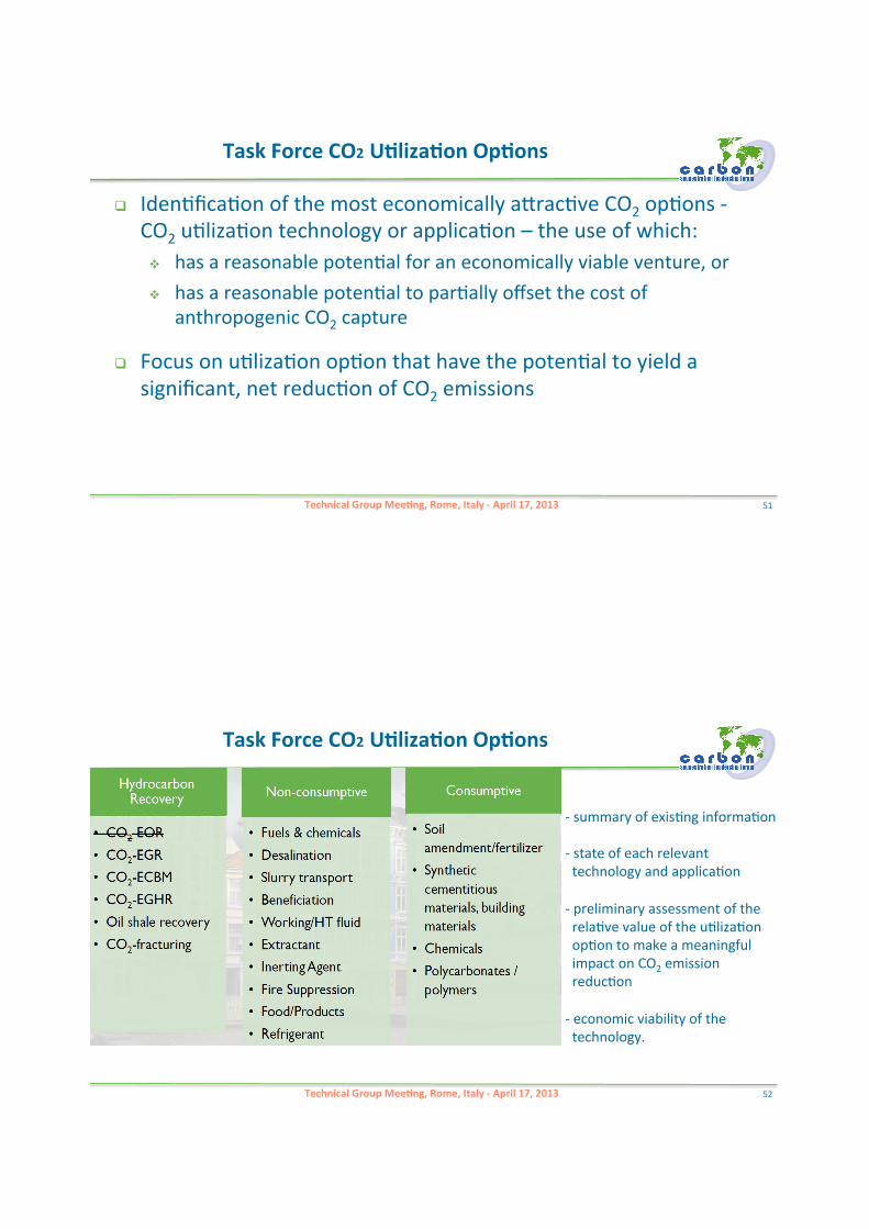
Technical'Group'Mee.ng,'Rome,'Italy'F'April'17,'2013
'''''Task'Force'CO2'U.liza.on'Op.ons'
! Iden@fica@on"of"the"most"economically"aZrac@ve"CO2"op@ons">"CO2"u@liza@on"technology"or"applica@on"–"the"use"of"which:"# has"a"reasonable"poten@al"for"an"economically"viable"venture,"or""# has"a"reasonable"poten@al"to"par@ally"offset"the"cost"of"
anthropogenic"CO2"capture"
! Focus"on"u@liza@on"op@on"that"have"the"poten@al"to"yield"a"significant,"net"reduc@on"of"CO2"emissions"
51"
Technical'Group'Mee.ng,'Rome,'Italy'F'April'17,'2013
> "summary"of"exis@ng"informa@on""> "state"of"each"relevant"""""technology"and"applica@on""> "preliminary"assessment"of"the""""rela@ve"value"of"the"u@liza@on""""op@on"to"make"a"meaningful""""impact"on"CO2"emission"""""reduc@on""> "economic"viability"of"the""""technology.""
'''''Task'Force'CO2'U.liza.on'Op.ons'
52"
Technical'Group'Mee.ng'Rome,'16'–'19'April,'2013
53"Technical'Group'Mee.ng,'Rome,'Italy'F'April'17,'2013
Thank'you'for'your'aben.on'
'
54"
Giuseppe"Girardi,"CSLF"–"ENEA"[email protected]
Technical'Group'Mee.ng,'Rome,'Italy'F'April'17,'2013
and'
see'you'in'Rome"
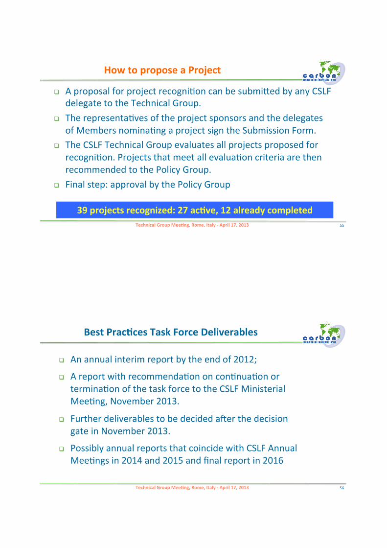
Technical'Group'Mee.ng,'Rome,'Italy'F'April'17,'2013
How'to'propose'a'Project
! A"proposal"for"project"recogni@on"can"be"submiZed"by"any"CSLF"delegate"to"the"Technical"Group."
! The"representa@ves"of"the"project"sponsors"and"the"delegates"of"Members"nomina@ng"a"project"sign"the"Submission"Form."
! The"CSLF"Technical"Group"evaluates"all"projects"proposed"for"recogni@on."Projects"that"meet"all"evalua@on"criteria"are"then"recommended"to"the"Policy"Group."
! Final"step:"approval"by"the"Policy"Group"
39'projects'recognized:'27'ac.ve,'12'already'completed
" 55"
! An"annual"interim"report"by"the"end"of"2012;""
! A"report"with"recommenda@on"on"con@nua@on"or"termina@on"of"the"task"force"to"the"CSLF"Ministerial"Mee@ng,"November"2013.""
! Further"deliverables"to"be"decided"aler"the"decision"gate"in"November"2013."""
! Possibly"annual"reports"that"coincide"with"CSLF"Annual"Mee@ngs"in"2014"and"2015"and"final"report"in"2016"
Best'Prac.ces'Task'Force'Deliverables
Technical'Group'Mee.ng,'Rome,'Italy'F'April'17,'2013 56"
• Rob"Arts,"Netherlands"• Andre"Bocin>Dumitriu,"EC"• Grant"Bromhal,"USA"• Andy"Chadwick,"UK"• Niels"Peter"Christensen,"
Norway"• Tim"Dixon,"UK/IEAGHG"• Bin"Gong,"China"• Qi"Li,"China"
• Xiaochun"Li,"China"• Jacques"Monne,"France"• Niels"Poulsen,"Denmark"• Jeroen"Schuppers,"EC"• Mar@n"Streibel,"germany"• Evangelos"Tzimas,"EC"• Trygve"Riis,"Norway""• Lars"Ingolf"Eide,"Norway"
Best'Prac.ces'Task'Force'Membership
Technical'Group'Mee.ng,'Rome,'Italy'F'April'17,'2013 57"
! Con@nue"assessment"of"standards/guidelines;"
! Establish"communica@on"with"the"ISO"CCS"working"group"Technical"CommiZee"(TC)"265"
Technical'Group'Mee.ng,'Rome,'Italy'F'April'17,'2013
Best'Prac.ces'Task'Force:'Next'step
58"