IT Appendice Tecnica Technical Appendix · 2018. 3. 30. · Appendice Tecnica Technical Appendix II...
16
Appendice Tecnica Technical Appendix IT EN
Transcript of IT Appendice Tecnica Technical Appendix · 2018. 3. 30. · Appendice Tecnica Technical Appendix II...

Appendice TecnicaTechnical Appendix
IT
EN
Appendice TecnicaTechnical Appendix
BIZZI & TEDESCHI
2
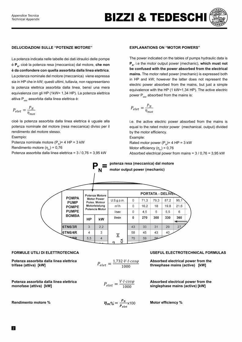
DELUCIDAZIONI SULLE “POTENZE MOTORE”
La potenza indicata nelle tabelle dei dati idraulici delle pompe è PN, cioè la potenza resa (meccanica) dal motore, che non è da confondere con quella assorbita dalla linea elettrica. La potenza nominale del motore (meccanica) viene espressa sia in HP che in kW; questi ultimi, tuttavia, non rappresentano la potenza elettrica assorbita dalla linea, bensì una mera equivalenza con gli HP (1kW= 1,34 HP). La potenza elettrica attiva Pelet assorbita dalla linea elettrica è:
= = 22,3 kW
cioè la potenza assorbita dalla linea elettrica è uguale alla potenza nominale del motore (resa meccanica) diviso per il rendimento del motore stesso.Esempio:Potenza nominale motore (PN)= 4 HP = 3 kWRendimento motore (ηm) = 0,76Potenza assorbita dalla linea elettrica = 3 / 0,76 = 3,95 kW
ExPLANATIONS ON “MOTOR POwERS”
The power indicated on the tables of pumps hydraulic data is PN, i.e the motor output power (mechanic), which must not be confused with the power absorbed from the electrical mains. The motor rated power (mechanic) is expressed both in HP and kW; however the latter does not represent the electric power absorbed from the mains, but just a simple equivalence with the HP (1 kW=1,34 HP). The active electric power Pelet absorbed from the mains is:
= = 22,3 kW
i.e. the active electric power absorbed from the mains is equal to the rated motor power (mechanical. output) divided by the motor efficiency.Example:Rated motor power (PN)= 4 HP = 3 kWMotor efficiency (ηm) = 0,76Absorbed electrical power from mains = 3 / 0,76 = 3,95 kW
PN= potenza resa (meccanica) dal motoremotor output power (mechanic)
x100%x100%
x100%
FORMULE UTILI DI ELETTROTECNICA
Potenza assorbita dalla linea elettrica trifase (attiva) [kw]
Potenza assorbita dalla linea elettrica monofase (attiva) [kw]
Rendimento motore %
USEFUL ELECTROTECHNICAL FORMULAS
Absorbed electrical power from the threephase mains (active) [kw]
Absorbed electrical power from the singlephase mains (active) [kw]
Motor efficiency %

Appendice TecnicaTechnical AppendixBIZZI & TEDESCHI
3
M.I.
P.
M.O
.P.
FLU
SSO
DEL
LA P
OTE
NZA
DA
LLA
LIN
EA E
LETT
RIC
A A
LLA
BO
CC
A D
I USC
ITA
DEL
L’EL
ETTR
OPO
MPA
SO
MM
ERSA
POW
ER F
LOW
FR
OM
ELE
CTR
IC M
AIN
S TO
SU
BM
ERSI
BLE
PU
MP
OU
TLET
P.O
.P.
PU
MP
MO
TOR
M. I. P.
M.
O. P.
M.I.
P.
electric power
mechanic power
hydr
aulic
pow
er
M.O
.P.
LEG
EN
DA
M.I.
P. =
Mot
or In
put P
ower
po
tenz
a as
sorb
ita
dalla
line
aM
.O.P
. =M
otor
Out
put P
ower
po
tenz
a re
sa a
ll’as
se
mot
ore
P.O
.P. =
Pum
p O
utpu
t Pow
er
pote
nza
idra
ulic
a
all’u
scita
pom
paηm
=
rend
imen
to m
otor
e
mot
or e
ffici
ency
ηp =
re
ndim
ento
pom
pa
pum
p ef
ficie
ncy
BIZ
ZI &
TED
ESC
HI
ATTE
NTI
ON
!Th
e po
wer
indi
cate
d on
the
cata
logu
e be
side
s the
pum
p TY
PE, i
s the
rate
d m
otor
out
put p
ower
(i.e
., ra
ted
M.O
.P.).
TH
E EL
ECTR
ICAL
PO
WER
ABS
ORB
ED
FRO
M T
HE
MAI
NS
CAN
BE
KNO
WN
CA
LCU
LATI
NG
IT B
Y D
IVID
ING
M.O
.P. B
Y TH
E M
OTO
R EF
FICI
ENCY
(see
lege
nda)
ATTE
NZI
ON
E!La
pot
enza
indi
cata
sul c
atal
ogo
a �a
nco
del T
IPO
pom
pa, è
la p
oten
za n
omin
ale
resa
all’
asse
mot
ore
(cio
è M
.O.P
. no
min
ale)
PER
OTT
ENER
E LA
PO
TEN
ZA A
SSO
RBIT
A D
ALLA
LIN
EA E
LETT
RICA
, OCC
ORR
E CA
LCO
LARL
A D
IVID
END
O M
.O.P.
PER
IL
REN
DIM
ENTO
DEL
MO
TORE
(ved
i leg
enda
).
RE
LAZI
ON
I - R
ELA
TIO
NS
M.I.
P.=
M.O
.P.
ηm
P.O
.P.=
M.O
.P. x
ηp

Appendice TecnicaTechnical Appendix
BIZZI & TEDESCHI
4
AvviamentoStarting
Tipo cavoCable type
Quadripolare / Quadripolar4x….. mm2
Unipolare / Unipolar1x….. mm2
N° caviCables Nr
Sezione cavoCable sect. mm2 1,5 2,5 4 6 10 16 25 35 50 50 70 95 120 150
DirettoD.O.L. 1 mm2 Imax [A] 16 22 32 42 58 80 101 125 154 200 245 294 350 410
Y/Δ 2 mm2 Imax [A] 28 38 55 73 100 138 175 216 266 346 424 509 606 710
Scelta cavo di alimentazione
La scelta del cavo di alimentazione del motore deve essere effettuato sulla base dei seguenti elementi:
• ΔU% [V%] =caduta di tensione che è consigliabile non superi il 3% della tensione nominale del motore
• IN [A] =Corrente nominale del motore• intensità di corrente massima sopportabile dal cavo• L [m] = lunghezza del cavo • cosφ = fattore di potenza del motore• T [°C] = temperatura ambiente
Passaggi per la scelta del cavo:1. In base alla corrente nominale del motore, si
sceglie la sezione minima del cavo rispettando la corrente massima del cavo stesso i cui valori sono indicati nella Tab. A
2. Si verifica che la caduta tensione lungo il cavo non superi il limite del 3% consigliato; qualora la caduta di tensione sia troppo elevata occorre scegliere la misura di cavo superiore ed effettuare di nuovo la verifica. Le formule per il calcolo della caduta di tensione sono indicate di seguito. Per una scelta veloce del cavo si rimanda alle tabelle di pag.6-7.
Se la temperatura ambiente T > 30°C, la capacità del cavo è ridotta.Imax della Tab. A deve essere diminuita del fattore K.
If ambient temperature T > 30°C, the allowable load is reduced. Imax in Tab. A must be devaluated by factor K.
Power supply cable choice
The choice of power supply cable is made on the basis of the following elements:
• ΔU% [V%] = Voltage drop which is advisable does not exceed 3% of the rated motor voltage
• IN [A] = Motor rated current• Maximum current intensity bearable by the cable• L [m] = Cable length • cosφ = motor power factor• T [°C] = ambient temperature
Steps for the choice of the power supply cable1. The choice of the minimum cross section of the
cable has to be carried out on the basis of the rated current of the motor, respecting the maximum cable load whose values are indicated on Tab. A.
2. It must be checked that the voltage drop along the cable does not exceed the advisable limit of 3%; should the voltage drop be too high, the bigger size cable must be chosen and another check of voltage drop has to be done. The formula to calculate the voltage drop are indicated hereunder. For a fast cable choice refer to tables of pag. 6-7.
Portata massima del cavo in PVC /H07RNF/EPR/EPDM alla temperatura ambiente di 30°C per posa in aria liberaTemperatura massima di esercizio del cavo 60°C
Max. load for cable in PVC/H07RNF/EPR/EPDM at ambient temperature of 30°C for laying in free airMax cable operating temperature 60°C
Imax= corrente massima assorbita dalla linea Imax= Max. current absorbed by the mains Tab. A
T °C
=30°C ≤ 35°C ≤ 40°C ≤ 45°C ≤ 50°C
K 1 0,92 0,81 0,72 0,62

Appendice TecnicaTechnical AppendixBIZZI & TEDESCHI
5
Valori della resistenza [Ω/km] e della reattanza [Ω/km] per cavi unipolari e multipolari (tripolare o quadripolare)
Calcolo della caduta di tensione lungo il cavo tenendo conto oltre che della resistenza anche della reattanza del cavo. La reattanza varia in base al numero di conduttori ed alla loro posizione tra loro. Vedi Tab.B
Dove:• ΔU% [V%] =caduta di tensione che è consigliabile non
superi il 3% della tensione nominale del motore • UN [V] = Tensione nominale del motore• IN [A] =Corrente nominale del motore• L [m] = lunghezza del cavo • cosφ = fattore di potenza del motore a pieno carico• q [mm2] = sezione del conduttore in rame
Value of the resistance [Ω/km] and reactance [Ω/km] for unipolar and multipolar (threepolar-quadripolar) cables
Calculation of the cable drop voltage considering, besides the resistance, the reactance of the cable. The reactance varies according to the number of leads and to the position among each other. Refer to Tab.B
Where:• ΔU% [V%] = Voltage drop which is advisable does not
exceed 3% of the rated motor voltage• UN [V] = Motor rated voltage• IN [A] = Motor rated current• L [m] = Cable length • cosφ = motor power factor at full load• q [mm2] = cross section of the copper wire
Tab. B
Caduta di tensione sul cavo per motori trifasi ad avviamento diretto/ impedenze /autotrasformatore (sola resistenza)1 cavo
Cable drop voltage for threephase motors for direct starting / by impedance/autotransformer (only resistance)1 cable
Caduta di tensione sul cavo per motori trifasi ad avviamento stella-triangolo (sola resistenza)2 cavi
Cable drop voltage for threephase motors for star-delta starting (only resistance)2 cables
Caduta di tensione sul cavo per motori monofasi (sola resistenza)
Cable drop voltage for singlephase motors (only resistance)
Motore trifase avviamento diretto Threephase motor D.O.L. starting
Motore trifase avviamento Y/Δ Threephase motor Y/Δ starting
Motore monofase Singlephase motor
Dove: Where:R [Ω]= resistenza ohmica del conduttore (vedi tab. B)X [Ω]= reattanza del conduttore (vedi tab. B)
R [Ω]= lead ohmic resistance (ref. tab. B)X [Ω]= lead reactance (refer tab. B)
Formule Formulas
SezioneSection
Unipolari MultipolareResistenza (60°C) Reattanza 50 Hz Resistenza (60°C) Reattanza 50 Hz
mm2 Ω/km Ω/km Ω/km Ω/km1,5 15.89 0.168 15.89 0.01182,5 9.52 0.155 9.52 0.1094 5.90 0.143 5.90 0.1016 3.93 0.135 3.93 0.0955
10 2.26 0.119 2.26 0.08616 1.44 0.112 1.44 0.081725 0.922 0.106 0.922 0.081335 0.665 0.101 0.665 0.078350 0.465 0.100 0.465 0.077970 0.321 0.0965 0.321 0.075195 0.244 0.0975 0.244 0.0762
120 0.191 0.0939 0.191 0.0740150 0.155 0.0928 0.155 0.0745
Appendice TecnicaTechnical Appendix
BIZZI & TEDESCHI
6
AVVIAMENTO DIRETTO O STATORICO - DIRECT OR STATORIC STARTINGDEMARRAGE DIRECT OU STATORIQUE - DIREKT- ODER STATORANLASSEN
ARRANQUE DIRECTO O ESTATORICO
POTENZA MOTOREMOTOR POwER
PUISSANCE MOTEURMOTOR LEISTUNGPOTENCIA MOTOR
TENSIONEVOLTAGETENSION
SPAN-NUNG
TENSION
N° 1 CAVI - SEZIONE 4x...mm2
N° 1 CABLES - SECTION 4x...mm2
N° 1 CABLE - SECTION 4x...mm2
Nr. 1 KABEL - SCHNITTFLÄCHE 4x...mm2
N° 1 CABLES - SECCION 4x...mm2
N° 3 CAVI UNIPOLARI - 1x...mm2
N° 3 SINGLE-wIRE CABLES - 1x...mm2
N° 3 CABLES UNIPOLAIRES - 1x...mm2
Nr. 3 EINLEITERKABEL - SCHNITTFLÄCHE1x...mm2
N° 3 CABLES UNIPOL. - SECCION - 1x...mm2
1,5 2,5 4 6 10 16 25 35 50 70 95
HP kw V LUNGHEZZA MAx. - MAx. LENGTH - LONGEUR MAx. - MAxIMALLÄNGE - LONGITUD MAx........m
3 2,2 230400 100
61185
92280
140 210
4 3 230400 80
40120
67200
97290
179
5,5 4 230400 100
53170
78250
148400
250
7,5 5,5 230400
44130
64190
108320
175
10 7,5 230400
35110
55170
90280
150450
12,5 9,2 230400 90
50140
80230
125335
180 240
15 11 230400 70
37115
70185
105300
150450
200
17,5 13 230400 100
58160
80250
120365
165505
20 15 230400 90
51140
75225
115340
150450
25 18,5 230400 110
60175
90275
125373
172515
30 22 230400 90 140
70225
100300
150437
35 26 230400 120
60200
85270
125373
171510
215
40 30 230400 110
58175
80240
110330
150450
190
50 37 230400 140 180
85260
125370
160480
60 45 230400 115 160
79230
110320
130400
70 51,5 230400 140 210
94275
120356
75 55 230400 134 190
89265
110330
80 59 230400 120 175
70245
100300
90 66 230400 160
73224
94283
100 75 230400 145
67200
85255
125 92 400 105 158 200
150 110 400 128 190
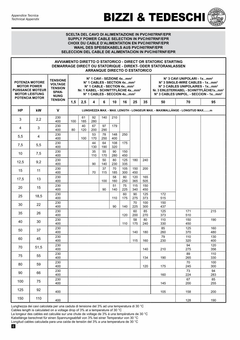
Lunghezza dei cavi calcolata per una caduta di tensione del 3% ad una temperatura di 30 °CCables length is calculated on a voltage drop of 3% at a temperature of 30 °CLa longeur des cables est calculée sur une chute de voltage de 3% à una température de 30 °CKabellänge berechnet für einen Spannungsabfall von 3% bei einer Temperatur von 30 °CLongitud cables calculada para una caìda de tensiòn del 3% a una temperatura de 30 °C
SCELTA DEL CAVO DI ALIMENTAZIONE IN PVC/H07RNF/EPRSUPPLY POwER CABLE SELECTION IN PVC/H07RNF/EPRCHOIx DU CABLE D’ALIMENTATION EN PVC/H07RNF/EPR
wAHL DES SPEISEKABELS AUS PVC/H07RNF/EPRSELECCION DEL CABLE DE ALIMENTACION IN PVC/H07RNF/EPR

Appendice TecnicaTechnical AppendixBIZZI & TEDESCHI
7
AVVIAMENTO STELLA-TRIANGOLO - STAR-DELTA STARTINGDEMARRAGE ETOILE-TRIANGLE - STERNDREIECKANLASSEN
ARRANQUE ESTRELLA-TRIANGULO
POTENZA MOTOREMOTOR POwER
PUISSANCE MOTEURMOTOR LEISTUNGPOTENCIA MOTOR
TENSIONEVOLTAGETENSION
SPANNUNGTENSION
N° 2 CAVI - SEZIONE 4x...mm2 +3x...mm2
N° 2 CABLES - SECTION 4x...mm2 +3x...mm2
N° 2 CABLE - SECTION 4x...mm2 +3x...mm2
Nr. 2 KABEL - SCHNITTFLÄCHE 4x...mm2 +3x...mm2
N° 2 CABLES - SECCION 4x...mm2 +3x...mm2
N° 6 CAVI UNIPOLARI - 1x...mm2
N° 6 SINGLE-wIRE CABLES - 1x...mm2
N° 6 CABLES UNIPOLAIRES - 1x...mm2
Nr. 6 EINLEITERKABEL - SCHNITTFLÄCHE1x...mm2
N° 6 CABLES UNIPOL. - SECCION - 1x...mm2
2,5 4 6 10 16 25 35 50 70 95
HP kw V LUNGHEZZA MAx. - MAx. LENGTH - LONGEUR MAx. - MAxIMALLÄNGE - LONGITUD MAx........m
5,5 4 230400
57169
92271
137406
236
7,5 5,5 230400 129
68201
101301
176511
10 7,5 230400 94
51151
76226
130386
204
12,5 9,2 230400 76
41121
61181
104310
162484
15 11 230400 67 106
53157
91271
142422
216
17,5 13 230400 91
46136
78231
122361
186
20 15 230400 78 117
68201
105311
160476
220
25 18,5 230400 64 94
55162
85252
129384
178531
30 22 230400 77 130
69204
104310
144426
200
35 26 230400 69 118
62184
94280
129385
180
40 30 230400 61 105
55163
84249
116344
160477
218
50 37 230400 87 133
69205
95282
132393
180
60 45 230400 74 113
59174
81240
112333
153455
193
70 51,5 230400 100
52153
71211
99293
134399
170506
75 55 230400 94 143
67200
95280
126380
163475
80 59 230400 80 134
63186
87258
118351
150446
90 66 230400 121
57168
79234
107318
136404
100 75 230400 109 150
71210
96285
121360
125 92 400 122 170 231 294
150 110 400 100 165 230 310
SCELTA DEL CAVO DI ALIMENTAZIONE IN PVC/H07RNF/EPRSUPPLY POwER CABLE SELECTION IN PVC/H07RNF/EPRCHOIx DU CABLE D’ALIMENTATION EN PVC/H07RNF/EPR
wAHL DES SPEISEKABELS AUS PVC/H07RNF/EPRSELECCION DEL CABLE DE ALIMENTACION IN PVC/H07RNF/EPR
Lunghezza dei cavi calcolata per una caduta di tensione del 3% ad una temperatura di 30 °CCables length is calculated on a voltage drop of 3% at a temperature of 30 °CLa longeur des cables est calculée sur une chute de voltage de 3% à una température de 30 °CKabellänge berechnet für einen Spannungsabfall von 3% bei einer Temperatur von 30 °CLongitud cables calculada para una caìda de tensiòn del 3% a una temperatura de 30 °C
Appendice TecnicaTechnical Appendix
BIZZI & TEDESCHI
8
La potenza apparente che i motori asincroni assorbono dalla linea elettrica è costituita da due tipi di potenze:
1. La potenza reale o attiva espressa in W o kW che è quella che viene trasformata in potenza meccanica
2. La potenza reattiva espressa in VAR o kVAR che rappresenta la potenza atta a costituire il campo magnetico sul quale si basa il funzionamento del motore.
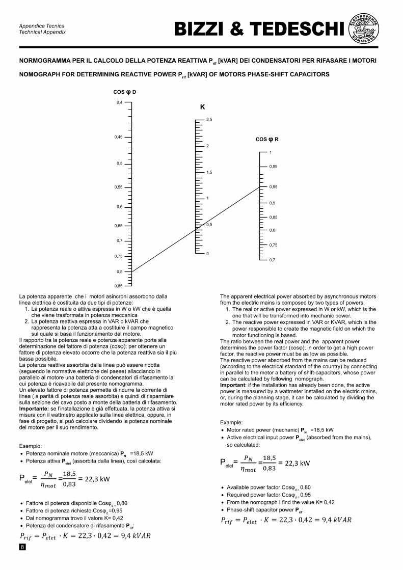
Il rapporto tra la potenza reale e potenza apparente porta alla determinazione del fattore di potenza (cosφ); per ottenere un fattore di potenza elevato occorre che la potenza reattiva sia il più bassa possibile.La potenza reattiva assorbita dalla linea può essere ridotta (seguendo le normative elettriche del paese) allacciando in parallelo al motore una batteria di condensatori di rifasamento la cui potenza è ricavabile dal presente nomogramma.Un elevato fattore di potenza permette di ridurre la corrente di linea ( a parità di potenza reale assorbita) e quindi di risparmiare sulla sezione del cavo posto a monte della batteria di rifasamento.Importante: se l’installazione è già effettuata, la potenza attiva si misura con il wattmetro applicato sulla linea elettrica, oppure, in fase di progetto, si può calcolare dividendo la potenza nominale del motore per il suo rendimento.
Esempio:• Potenza nominale motore (meccanica) PN =18,5 kW • Potenza attiva Pelet (assorbita dalla linea), così calcolata:
Pelet=
= = 22,3 kW
• Fattore di potenza disponibile Cosφd = 0,80
• Fattore di potenza richiesto Cosφd =0,95• Dal nomogramma trovo il valore K= 0,42• Potenza del condensatore di rifasamento Prif:
= = 22,3 kW
The apparent electrical power absorbed by asynchronous motors from the electric mains is composed by two types of powers:
1. The real or active power expressed in W or kW, which is the one that will be transformed into mechanic power.
2. The reactive power expressed in VAR or KVAR, which is the power responsible to create the magnetic field on which the motor functioning is based.
The ratio between the real power and the apparent power determines the power factor (cosφ); in order to get a high power factor, the reactive power must be as low as possible.The reactive power absorbed from the mains can be reduced (according to the electrical standard of the country) by connecting in parallel to the motor a battery of shift-capacitors, whose power can be calculated by following nomograph.Important: if the installation has already been done, the active power is measured by a wattmeter installed on the electric mains, or, during the planning stage, it can be calculated by dividing the motor rated power by its efficiency.
Example:• Motor rated power (mechanic) PN =18,5 kW• Active electrical input power Pelet (absorbed from the mains),
so calculated:
Pelet= = = 22,3 kW
• Available power factor Cosφd = 0,80
• Required power factor Cosφd = 0,95• From the nomograph I find the value K= 0,42• Phase-shift capacitor power Prif:
= = 22,3 kW
1
0,99
0,95
0,9
0,85
0,8
0,75
0,7
COS φ R
K2,5
2
1,5
1
0,5
0
COS φ D
0,4
0,45
0,5
0,55
0,6
0,65
0,7
0,75
0,8
0,85
NORMOGRAMMA PER IL CALCOLO DELLA POTENZA REATTIVA Prif [kVAR] DEI CONDENSATORI PER RIFASARE I MOTORI
NOMOGRAPH FOR DETERMINING REACTIVE POwER Prif [kVAR] OF MOTORS PHASE-SHIFT CAPACITORS

Appendice TecnicaTechnical AppendixBIZZI & TEDESCHI
9
POTENZA MOTOREMOTOR POwER
PUISSANCE MOTEURMOTOR LEISTUNGPOTENCIA MOTOR
POTENZA MINIMA DEL GENERATOREMINIMUM POwER OF THE GENERATORPUISSANCE MINIMALE DU GENERATOR
LEISTUNG DES GENERATORSPOTENCIA MINIMA DEL GENERADOR
AVVIAMENTO DIRETTODIRECT STARTING
DEMARRAGE DIRECTDIREKTANLASSEN
ARRANQUE DIRECTO
HP kw kw kVA
3 2,2 6 7,5
4 3 8 10
5,5 4 10 12,5
7,5 5,5 12,5 15,5
10 7,5 15 19
12,5 9,2 19 24
15 11 22,5 28
17,5 13 26,5 33
20 15 30 38
25 18,5 40 50
30 22 45 57
35 26 52 65
40 30 60 75
50 37 75 94
60 45 90 112
70 51,5 105 131
75 55 110 138
80 59 120 150
90 66 135 170
100 75 150 190
125 92 185 230
150 110 210 260
POTENZA MOTOREMOTOR POwER
PUISSANCE MOTEURMOTOR LEISTUNGPOTENCIA MOTOR
POTENZA MINIMA DEL GENERATOREMINIMUM POwER OF THE GENERATORPUISSANCE MINIMALE DU GENERATOR
LEISTUNG DES GENERATORSPOTENCIA MINIMA DEL GENERADOR
AVVIAMENTO STELLA-TRIANGOLOSTAR-DELTA STARTING
DEMARRAGE ETOILE-TRIANGLESTERNDREIECKANLASSEN
ARRANQUE ESTRELLA-TRIANGULO
HP kw kw kVA
- - - -
4 3 6 7,5
5,5 4 8 10
7,5 5,5 10,8 13,5
10 7,5 14 17,5
12,5 9,2 17 21
15 11 21 26
17,5 13 24 30
20 15 28 35
25 18,5 33 42
30 22 40 50
35 26 45 57
40 30 52 65
50 37 64 80
60 45 77 97
70 51,5 90 112
75 55 95 119
80 59 102 128
90 66 115 144
100 75 128 160
125 92 158 198
150 110 190 240
SCELTA DEL GRUPPO ELETTROGENO ADATTO PER IL FUNZIONAMENTO DELL’ELETTROPOMPA SOMMERSASELECTION OF THE GENERATING SET SUITABLE TO POwER THE SUBMERSIBLE ELECTRIC PUMPCHOIx D’UN GROUPE ELECTROGENE POUR ALIMENTATION D’UNE ELECTROPOMPE IMMERGEE
wAHL DES GENERATORSATZES PASSEND ZUM BETRIEB DER ELEKTROTAUCHPUMPESELECCION DEL GRUPO ELETROGENO ADECUADO PARA EL FUNCIONAMIENTO DE LA ELECTROBOMBA SUMERGIBLE

Appendice TecnicaTechnical Appendix
BIZZI & TEDESCHI
10
La pompa sommersa è una macchina idraulica operatrice che, azionata opportunamente da un motore elettrico, comunica energia all’acqua al fine di sollevarla ad una certa altezza o per convogliarla ad una certa distanza, o per imprimerle una certa velocità.Le grandezze che caratterizzano una pompa centrifuga sommersa sono:la portata e la prevalenza.• La portata è il volume d’acqua che attraversa la
pompa nell’unità di tempo ed è espressa in l/min, o m3/h o l/sec….
• La prevalenza è definita come la differenza fra l’energia totale posseduta da 1 kg di acqua all’uscita della pompa e quella posseduta al suo ingresso; più semplicemente, è la pressione a cui la pompa porta l’acqua nel punto costituito dalla bocca di mandata della pompa stessa.
Per l’applicazione classica delle pompe sommerse (vedi schema 1), la misura della prevalenza totale avviene con la seguente formula 1:
The submersible pump is an hydraulic operating machine that, properly driven by an electric motor, supplies energy to water in order to raise it at a certain height, or to convey it at a certain distance, or to set it in motion at a certain speed.The feature quantities of a centrifugal submersible pump are: discharge and head. • The discharge is the water volume that passes
through the pump in the unit of time and it is expressed in l/min or m3/h or l/sec…
• The head is defined as the difference between the total energy possessed by 1 kg of water at the pump outlet and the one at its inlet; more simply, it is the pressure given to water by the pump in the point of the delivery casing.
For the classic application of submersible pumps (see layout 1), the measure of the total head is carried out by using the following formula 1:
COME FUNZIONA UNA POMPA SOMMERSA HOw A SUBMERSIBLE PUMP wORKS
dove:• Ht = prevalenza totale della pompa [m di H2O]• Pm = pressione [m di H2O] indicata dal manome-
tro• Z1 = profondità o livello dinamico dell’acqua nel
pozzo rispetto al livello terreno [m]• Z2 = altezza tra il centro del manometro ed il li-
vello terreno [m]• Hy = perdita di carico dovuto all’attrito dinamico
dell’acqua lungo la tubazione dalla sezione A alla sezione C [m di H2O]
• U2 = Velocità acqua nella sezione C [m/sec]• g = accelerazione di gravità [m/sec2]
where:• Ht = total pump head [m di H2O]• Pm = pressure [m of H2O] indicated by pressure
gauge• Z1 = depth or dynamic level of the water into the
well referred to the ground level [m]• Z2 = height between the centre of pressure
gauge and the ground level [m]• Hy = fiction losses due to the water dynamic
fiction along the pipe from sections A to C [m of H2O]
• U2 = water speed in section C [m/sec]• g = gravity acceleration [m/sec2]
1Z1Z2
U2
5
4
A
C
Pm2
3 Q
1 Piano terrenoGround level
2 ManometroPressure gauge
3 FlussometroFlowmeter
4 SaracinescaGate valve
5 Livello acqua Water level
Schema di misura portata-prevalenza di una pompa sommersaLayout for discharge-head measure of a submersible pump
schema 1layout 1
(formula 1)
Formula per calcolo prevalenza totale pompaFormula for calculation pump total head

Appendice TecnicaTechnical AppendixBIZZI & TEDESCHI
11
FUNZIONE DELL’ACQUA ASPIRATA DALLA POMPA
L’acqua aspirata dalla pompa, lambendo il motore con una certa velocità VC, esegue una funzione molto importante che è il raffreddamento del motore stesso.. Pertanto, come indicato nella fig. A, il flusso dell’acqua deve provenire da sotto il motore e, contestualmente, occorre che VC sia superiore al valore minimo richiesto, affinchè il raffreddamento sia efficace (i valori di VC minimi per i motori PA6-PA8 sono indicati nelle Tab. 1-2 a pag 8 della specifica brochure).
• Q [m3/h]= portata minima per soddisfare la condizione minima di raffreddamento
• VC min [m/sec] = valore minimo ammissibile della velocità di circolazione acqua intorno al motore
• Ø1 [mm]= diametro interno del pozzo o della campana in prossimità del motore
• Ømot [mm]= diametro esterno del motore
Qualora i filtri di adduzione acqua del pozzo siano più alti della posizione del motore, oppure che la VC sia troppo bassa o di valore zero (come nel caso di installazioni in laghi o grandi vasche), occorre installare intorno all’elettropompa una “camicia di induzione” (campana) di diametro adeguato, posizionandola in modo che l’acqua provenga da sotto il motore (vedi Fig.B).
Per ottenere una VC superiore al minimo richiesto occorre che il diametro interno della campana Ø1 sia inferiore a:
In case the well’s filters for water adduction are placed higher than motor’s position, or if VC is too low (or of zero value, as for installations in lakes or in big tanks), it is necessary to install “an inducer sleeve” around the pump of proper diameter, positioning it so that water comes from the bottom of the motor.
In order to get a VC higher than the minimum required value the internal sleeve diameter of Ø1 must be lower than:
• Q [m3/h]= minimum discharge to satisfy the minimum cooling condition of the motor
• VC min [m/sec]= allowable minimum value of the water flow speed around the motor
• Ø1 [mm] = internal diameter of the well or of the inducer sleeve in proximity of the motor
• Ømot [mm]= external motor diameter
Formula per la verifica della portata minima atta a garantire un sufficiente raffreddamento del motore
Formula to check the minimum discharge suitable to assure the minimum cooling conditions of the motor
FUNCTION OF THE wATER DRAwN BY THE PUMP
The water drawn by the pump, licking up the motor at a certain speed VC, carries out a very important function which is the motor cooling.Therefore, as shown in fig. A, the water flow must come from the bottom of the motor and, at the same time, VC needs to be higher than its minimum required value, in order to get the proper cooling ( the values of minimum VC for motors PA6-PA8 are shown in Tables 1-2 at page 8 of the specific brochure).
Ø1
Ø1
Ø MOT. Ø MOT.
fig.1
fig.2

Appendice TecnicaTechnical Appendix
BIZZI & TEDESCHI
12
x100%
x100%
Potenza meccanica assorbita dalla pompa (Ppi)
dove:• Ppi = potenza meccanica assorbita dalla
pompa [kW]• γ = peso specifico dell’acqua [kg/dm3 ] (nei
dati di catalogo si intende pari a 1 kg/dm3)• Q = portata [l/sec]• Ht = prevalenza totale della pompa [in m di
H2O]• ηp= rendimento della pompa
Variazioni delle prestazioni idrauliche al variare della velocità di rotazione (n)La prestazioni idrauliche Q-H sono fornite per una determinata velocità di rotazione (n1). Se tale velocità varia in n2 le nuove prestazioni possono essere calcolate secondo la legge di similitudine seguente, purchè non intervengano fenomeni di cavitazione:
Le formule della legge di similitudine trovano la loro applicazione nell’uso degli inverter (convertitori di frequenza); al posto del numero di giri n si pongono le frequenze. Esempio:
F1= 50 Hz F2=40 Hz
x100%
0,8
Q2 , la portata alla frequenza F2 , diminuisce del 20% rispetto alla frequenza F1.
The formula of symmetry law find their application in the use of inverters (frequency converters); we put the frequencies in the place of r.p.m (n). For example:
F1= 50 Hz F2=40 Hz
x100%
0,8
Q2 , the discharge at frequency F2 , decreases of 20% with respect to frequency F1.
Variations of hydraulic performances by varing the r.p.m. pump rotation speed (n)The hydraulic performances Q-H are supplied for a certain rotation speed (n1). If this speed varies into n2, the new performances can be calculated according to the following symmetry law, provided that no cavitations phenomena appear:
x100%
Potenza idraulica erogata dalla pompa (Ppo)Hydraulic delivered pump power (Ppo pump output power)
Mechanical power absorbed by the pump pump Ppi (pump input power)
where:• Ppi = mechanical power absorbed by the
pump [kW]• γ= specific weight of water [kg/dm3] (in
the catalogue data is meant equal to 1 kg/dm3)
• Q = discharge [l/sec]• Ht = total head of the pump [in m di H2O]• ηp = pump efficiency
Formule di meccanica idraulica Hydraulic mechanic formulas
x100%
0,64
H2 , la prevalenza alla frequenza F2 , diminuisce del 36% rispetto alla frequenza F1.
x100%
0,64
H2 , the head at frequency F2 , decreases of 36% with respect to frequency F1.
x100%
0,512
P2 , la potenza alla frequenza F2 , diminuisce del 49% rispetto alla frequenza F1.
x100%
0,512
P2 , the power at frequency F2 , decreases of 49% with respect to frequency F1.
IMPORTANTE:L’utilizzo del variatore di frequenza (inverter) nelle pompe sommerse deve tenere conto che la frequenza minima consentita è per la maggioranza dei costruttori di 30 Hz. Questo per garantire una corretta funzionalità dei cuscinetti del motore ed, in particolare, per mantenere una sufficiente capacità di carico del cuscinetto Mitchell reggispinta.In ogni caso si deve sempre verificare che la portata della pompa produca una velocità di circolazione dell’acqua intorno al motore (Vc) sufficiente per garantirne un corretto raffreddamento come spiegato a pag.11
IMPORTANT:The use of frequency converter (inverter) for submersible pumps must take into account that the minimum allowable frequency is 30 Hz for most of manufactures. This in order to guarantee a proper functionality of the motor bearing bushes, specifically to keep a sufficient load capacity of the Mitchell thrust bearing. In any case, it must be checked that the discharge of the pump provides a water flow speed (Vc) around the motor suitable for its proper cooling, as explained at page 11.

Appendice TecnicaTechnical AppendixBIZZI & TEDESCHI
13
PORTATADELIVERY - DEBIT
FORDERLEISTUNG - CAUDAL
vh
DIAMETRO NOMINALE IN mm E IN POLLICINOMINAL DIAMETER IN mm AND INCHES - DIAMETRE DU TUYAU EN mm ET EN POUCES
NENNwEITE IN mm UND ZOLL - DIAMETRO NOMINAL EN mm Y EN PULGADAS
m3/h l / min 203/4”
251”
321”1/4
401”1/2
502”
652”1/2
803”
1004”
1255”
1506”
1757”
2008”
25010”
1,2 20
V (m
/s) =
VE
LOC
ITA’
DE
LL’A
CQ
UA
- WAT
ER
VE
LOC
ITY
- VIT
ES
SE
DE
L’E
AU
- W
AS
SE
RG
ES
CH
WIN
DIG
KE
IT -
VE
LOC
IDA
D D
EL
AG
UA
h (m
) = P
ER
DIT
A D
I CA
RIC
O (I
N m
OG
NI 1
00 m
DI T
UB
AZI
ON
E) -
FR
ICTI
ON
LO
SS
(IN
m E
VE
RY
100
m O
F P
IPE
LIN
E) -
PE
RTE
S D
E C
HA
RG
E (E
N m
PO
UR
100
m D
E T
UYA
UTE
RIE
)E
NE
RG
IEG
EFÄ
LLE
(IN
m J
E 1
00 m
LE
ITU
NG
) - P
ER
DID
AS
DE
CA
RG
A (E
N m
CA
DA
100
m D
E T
UB
ER
IA)
vh
1,0510,4
0,73,72
0,420,95
0,260,31
1,5 25 vh
1,3115,8
0,885,68
0,521,47
0,330,47
1,8 30 vh
1,5622,3
1,058
0,622,09
0,40,66
2,1 35 vh
1,8229,8
1,2210,8
0,722,81
0,460,89
0,310,31
2,4 40 vh
2,138,2
1,413,8
0,832,65
0,531,15
0,350,4
3 50 vh
2,5858,2
1,7421,1
1,055,6
0,661,75
0,440,61
3,6 60 vh
3,182
2,130
1,258
0,792,48
0,520,86
4,2 70 vh
2,4340
1,4510,8
0,923,33
0,61,14
4,8 80 vh
2,7751,5
1,6613,9
1,054,3
0,681,46
5,4 90 vh
3,164
1,8717,5
1,185,4
0,771,82
0,450,46
6 100 vh
3,4579
2,0821,4
1,316,6
0,862,22
0,50,56
7,5 125 vh
2,633
1,6310
1,073,4
0,630,86
9 150 vh
3,1247
1,9614,2
1,274,74
0,741,21
0,490,43
10,5 175 vh
3,6463
2,2819
1,486,3
0,871,63
0,580,57
12 200 vh
4,282
2,624,5
1,688,1
12,1
0,660,74
15 250 vh
3,2437,5
2,112,3
1,253,2
0,821,12
0,530,36
18 300 vh
3,953
2,5117,3
1,54,5
0,981,58
0,620,51
24 400 vh
3,3229,5
1,977,8
1,32,7
0,840,89
30 500 vh
4,1344,8
2,4612
1,634,13
1,061,36
0,70,48
36 600 vh
2,9516,9
1,955,8
1,261,93
0,840,68
42 700 vh
3,4322,6
2,37,8
1,482,6
0,980,9
48 800 vh
3,929
2,610
1,683,35
1,111,16
0,750,43
54 900 vh
4,436
2,912,5
1,894,2
1,251,45
0,850,54
60 1000 vh
3,215,2
2,15,14
1,381,76
0,940,66
75 1250 vh
423
2,637,9
1,732,68
1,181
0,880,48
90 1500 vh
4,832,6
3,1511,2
2,063,77
1,411,42
1,060,68
105 1750 vh
3,6815
2,45,04
1,641,9
1,230,91
0,940,45
120 2000 vh
4,219,4
2,746,5
1,872,43
1,41,18
1,070,58
150 2500 vh
5,2430
3,419,8
2,333,75
1,761,79
1,330,89
180 3000 vh
4,113,8
2,85,3
2,12,53
1,61,25
240 4000 vh
5,423,8
3,729,13
2,784,36
2,122,16
1,360,71
300 5000 vh
4,6313,9
3,56,6
2,633,29
1,71,1
360 6000 vh
5,6820
4,169,5
3,184,7
2,051,6
420 7000 vh
4,8612,8
3,716,4
2,382,1
480 8000 vh
5,5521
4,2510,5
2,723,5
TABELLA DELLE PERDITE DI CARICO PER 100 m DI TUBAZIONE NUOVA E DIRITTA DI GHISAFRICTION LOSSES EVERY 100 m OF CAST IRON NEw AND STRAIGHT PIPELINE
PERTES DE CHARGE POUR 100 m DE TUYAUTERIE NOUVELLE ET DROITE EN FONTEENERGIEGEFÄLLE JE 100 m NEUER UND GERADER LEITUNG AUS GUß
PERDIDAS DE CARGA CADA 100 m DE TUBERIA NUEVA Y RECTA EN FUNDICION
LE PERDITE DI CARICO h DEVONO ESSERE MOLTIPLICATE PER:FRICTION LOSSES h SHOULD BE MULTIPLIED BY:LES PERTES DE CHARGE h DOIVENT ETRE MULTIPLIES POUR:DIE h ENERGIEGEFÄLLE MÜSSEN MULTIPLIZIERT WERDEN MIT:LAS PERDIDAS DE CARGA h DEBEN SER MULTIPLICADAS POR:*0,8 per tubi in acciaio nuovi - for new steel pipes - pour tuyaux nouveaux en acier Für neue Leitungen aus Stahl - por tubos nuevos en acero*1,25 per tubi in acciaio leggermente arrugginiti - for slightly rusty steel pipes pour tuyaux légèrement rouillés en acier - Für leicht verrostete Leitungen por tubos en acero levemente oxidados*0,7 per tubi in alluminio - for aluminium pipes - pour tuyaux en aluminium Für Aluminiumleitungen - por tubos en aluminio*0,65 per tubi in PVC - for PVC pipes - pour tuyaux en PVC Für PVC-Leitungen - por tubos en PVC
Appendice TecnicaTechnical Appendix
BIZZI & TEDESCHI
14
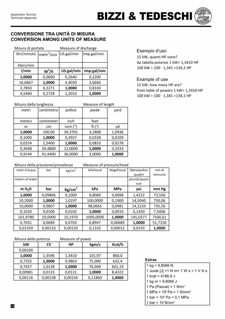
Conversione tra unità di misura Conversion between units of measure
Misura di portata Measure of dischargelitri/minuto metri3/ora US.gal/min Imp.gal/min
liters/minl/min M3/h US.gal/min Imp.gal/min
1,0000 0,0600 0,2640 0,220016,6667 1,0000 4,4030 3,66603,7850 0,2271 1,0000 0,83304,5460 0,2728 1,2010 1,0000
Misura della lunghezza Measure of lengthmetri centimetro pollice piede
meters centimeter inch feetm cm inch (“) ft (‘) yd
1,0000 100,00 39,3701 3,2808 1,09360,1000 1,0000 0,3937 0,0328 0,01090,0254 2,5400 1,0000 0,0833 0,02780,3048 30,4800 12,0000 1,0000 0,33330,9144 91,4400 36,0000 3,0000 1,0000
Misura della pressione/prevalenza Measure of pressure/headmetri d'acqua bar Kg/cm2 kiloPascal MegaPascal libbra/pollice
quadrometers of water pound/square
inch
m H2O bar Kg/cm2 kPa MPa psi mm Hg
1,0000 0,09806 0,1000 9,8060 0,0098 1,4222 73,55010,2000 1,0000 1,0197 100,0000 0,1000 14,5040 750,0610,0000 0,9807 1,0000 98,0665 0,0981 14,2233 735,560,1020 0,0100 0,0102 1,0000 0,0010 0,1450 7,5006
101,9780 10,0000 10,1970 1000,0000 1,0000 145,0377 7500,610,7031 0,0689 0,0703 6,8947 0,00689 1,0000 51,7150
0,01359 0,00133 0,00135 0,1333 0,00013 0,0193 1,0000
Misura della potenza Measure of powerkW CV HP kgm/s Kcal/h
0,001001,0000 1,3596 1,3410 101,97 860,00,7355 1,0000 0,9863 75,000 632,40,7457 1,0138 1,0000 76,040 641,19
0,00981 0,0133 0,0131 1,0000 8,43220,00116 0,00158 0,00156 0,11860 1,0000
Joule =1 Nxm= 1 Wxs = 1 VxAxs
Esempio d'uso
yard
mm di mercurio
CONVERSIONE TRA UNITÀ DI MISURACONVERSION AMONG UNITS OF MEASURE
15 kW, quanti HP sono?da tabella potenze 1 kW= 1,3410 HP100 kW = 100 · 1,341 =134,1 HP
Exmple of use15 kW, how many HP are?from table of powers 1 kW= 1,3410 HP100 kW = 100 · 1,341 =134,1 HP
15 kW, quanti HP sono?da tabella potenze 1 kW= 1,3410 HP100 kW = 100 · 1,341 =134,1 HP
Exmple of use15 kW, how many HP are?from table of powers 1 kW= 1,3410 HP100 kW = 100 · 1,341 =134,1 HP
Esempio d’uso
Example of use
1 kg = 9,8066 N1 Joule [J] =1 N·m= 1 W·s = 1 V·A·s1 kcal = 4186,8 J1 kg·m = 9,8066 J1 Pa (Pascal) = 1 N/m2
1 MPa = 106 Pa = 1 N/mm2
1 bar = 105 Pa = 0,1 MPa1 bar = 10 N/cm2
Extras

Appendice TecnicaTechnical AppendixBIZZI & TEDESCHI
15
Schema generale di installazione elettropompa sommersaGeneral layout of an electric submersible pump installation
16
17
18
1 2 3 4 5
19
14
15
H2O
1312
116
7
8
9
10A
10B
L1
L2
F>3m
E>1m
1 Quadro elettrico Electric panel2 Coperchio pozzo Well cover3 Manometro Pressure gauge4 Saracinesca regolazione portata Gate valve5 Valvola di ritegno (opzionale) Non-return valve (optional)6 Cavo di alimentazione Main electric cable7 Sonda controllo livello acqua (massimo) Water control detector (upper)8 Sonda controllo livello acqua (minimo) Water control detector (lower)9 Sonda comune Common electrode
10A Elettropompa sommersa (parte pompa) Submersible pump10B Elettropompa sommersa (parte motore) Submersible motor11 Curva Elbow12 Morsetto di sostegno Support clamp13 Fascetta fissaggio cavo Cable clamp14 Tubazione di mandata Delivery pipe15 Filtro del pozzo Well grid16 Tubazione di mandata Delivery pipe17 Valvola aria Air valve18 Autoclave o serbatoio Pressure tank or open tank19 Pressostato o galleggiante Pressure or float switchL1 Livello statico dell’acqua nel pozzo Water level into the well (static)L2 Livello dinamico dell’acqua nel pozzo Water level into the well (dynamic)

Via Brodolini, 35/A Campegine (Reggio Emilia) - ItalyTel. (+39) 0522.677209 - Fax (+39) 0522.677633
[email protected] - www.bizzi.it
BIZZI & TEDESCHI
AP
PE
ND
IX-B
R re
v02