Integrazione edilizia delle superfici fotovoltaiche
7
Integrazione edilizia delle superfici fotovoltaiche Tratto da: Architettura Integrata fischer Italia 2008 - Tutti i diritti riservati
-
Upload
fischeritalia -
Category
Documents
-
view
217 -
download
0
description
Integrazione edilizia delle superfici fotovoltaiche Tratto da: Architettura Integrata fischer Italia 2008 - Tutti i diritti riservati
Transcript of Integrazione edilizia delle superfici fotovoltaiche
Integrazione edilizia delle superfi ci fotovoltaicheTratto da:
Architettura Integrata
fi scher Italia 2008 - Tutti i diritti riservati
20
Inte
graz
ione
edi
lizia
delle
sup
erfic
i fot
ovol
taic
he
Integrazione ediliziadelle superfici fotovoltaiche
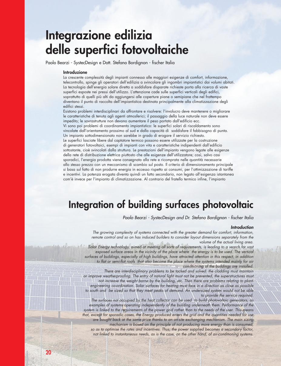
IntroduzioneLa crescente complessità degli impianti connessa alle maggiori esigenze di comfort, informazione,telecontrollo, spinge gli operatori dell’edilizia a svincolare gli ingombri impiantistici dai volumi abitati.La tecnologia dell’energia solare diretta a soddisfare disparate richieste porta alla ricerca di vastesuperfici esposte nei pressi dell’utilizzo. L’attenzione cade sulle superfici verticali degli edifici,soprattutto di quelli più alti da aggiungersi alle coperture piane o semipiane che nel frattempodiventano il punto di raccolta dell’impiantistica destinata principalmente alla climatizzazione degliedifici stessi.Esistono problemi interdisciplinari da affrontare e risolvere: l’involucro deve mantenere o migliorare le caratteristiche di tenuta agli agenti atmosferici; il passaggio della luce naturale non deve essereimpedito; le sovrastrutture non devono aumentare il peso portato dall’edificio ecc. Vi sono poi problemi di coordinamento impiantistico: le superfici solari di riscaldamento sonovincolate dall’orientamento prossimo al sud e dalla capacità di soddisfare il fabbisogno di punta. Un impianto sottodimensionato non sarebbe in grado di erogare il servizio richiesto.Le superfici lasciate libere dal captatore termico possono essere utilizzate per la costruzione di generatori fotovoltaici, esempi di impianti con vita e caratteristiche indipendenti dall’edificiosottostante, cioè svincolati dalla struttura. Le prestazioni dell’impianto vengono legate alle esigenzedella rete di distribuzione elettrica piuttosto che alle esigenze dell’utilizzatore; così, salvo casisporadici, l’energia prodotta viene consegnata alla rete e ricomprata nelle quantità necessarie allo stesso prezzo con un meccanismo di scambio sul posto. Il criterio di dimensionamento principalesi basa sul fatto di non produrre energia in eccesso rispetto ai consumi, per l’ottimizzazione di tariffee incentivi. La potenza erogata diventa quindi un fatto secondario, non legato all’esigenza istantaneacom’è invece per l’impianto di climatizzazione. Al contrario del fratello termico infine, l’impianto
Integration of building surfaces photovoltaic
IntroductionThe growing complexity of systems connected with the greater demand for comfort, information,
remote control and so on has induced builders to consider layout dimensions separately from thevolume of the actual living area.
Solar Energy technology, aimed at meeting all sorts of requirements, is leading to a search for vastexposed surface areas in the vicinity of the place where the energy is to be used. The vertical
surfaces of buildings, especially of high buildings, have attracted attention in this respect, in additionto flat or semi-flat roofs that also become the place where the systems intended mainly for air
conditioning of the buildings are installed.There are interdisciplinary problems to be tacked and solved: the cladding must maintain
or improve weatherproofing. The entry of natural light must not be prevented, the superstructures mustnot increase the weight borne by the building, etc. Then there are problems relating to plant-
engineering co-ordination. Solar surfaces for heating must face in a direction as close as possible to south and be sized so that they meet peaks of demand. An undersized system would not be able
to provide the service required.The surfaces not occupied by the heat collector can be used to build photovoltaic generators, as
examples of systems operating independently of the building underneath them. Performance of thesystem is linked to the requirements of the power grid rather than to the needs of the user. This means
that, except for sporadic cases, the Energy produced enters the grid and the quantities needed for useare bought back at the same price thanks to an on-site exchanging mechanism. The main sizing
mechanism is based on the principle of not producing more energy than is consumed, so as to optimise the rates and incentives. Thus, the power supplied becomes a secondary factor, not linked to instantaneous needs, as is the case, on the other hand, of air-conditioning systems.
Paolo Bearzi - SystecDesign e Dott. Stefano Bordignon - fischer Italia
Paolo Bearzi - SystecDesign and Dr. Stefano Bordignon - fischer Italia
20_25 FISHER_FOTOVOLTAICHE 10-11-2008 14:07 Pagina 20
21
fotovoltaico viene utilizzato integralmente per tutto l’anno: diversi saranno i criteridi dimensionamento progettuale.
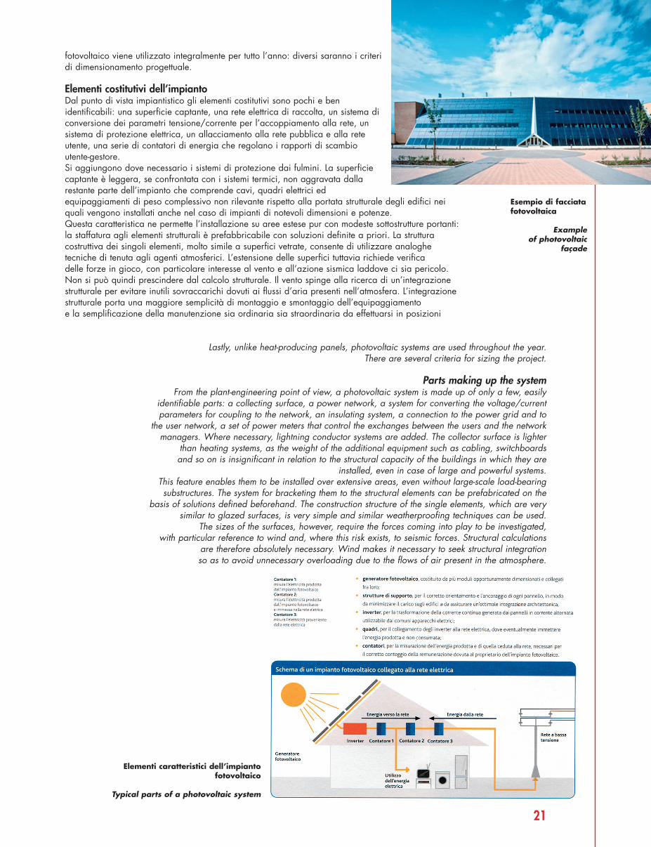
Elementi costitutivi dell’impiantoDal punto di vista impiantistico gli elementi costitutivi sono pochi e benidentificabili: una superficie captante, una rete elettrica di raccolta, un sistema diconversione dei parametri tensione/corrente per l’accoppiamento alla rete, unsistema di protezione elettrica, un allacciamento alla rete pubblica e alla reteutente, una serie di contatori di energia che regolano i rapporti di scambioutente-gestore. Si aggiungono dove necessario i sistemi di protezione dai fulmini. La superficiecaptante è leggera, se confrontata con i sistemi termici, non aggravata dallarestante parte dell’impianto che comprende cavi, quadri elettrici edequipaggiamenti di peso complessivo non rilevante rispetto alla portata strutturale degli edifici neiquali vengono installati anche nel caso di impianti di notevoli dimensioni e potenze.Questa caratteristica ne permette l’installazione su aree estese pur con modeste sottostrutture portanti:la staffatura agli elementi strutturali è prefabbricabile con soluzioni definite a priori. La strutturacostruttiva dei singoli elementi, molto simile a superfici vetrate, consente di utilizzare analoghetecniche di tenuta agli agenti atmosferici. L’estensione delle superfici tuttavia richiede verifica delle forze in gioco, con particolare interesse al vento e all’azione sismica laddove ci sia pericolo. Non si può quindi prescindere dal calcolo strutturale. Il vento spinge alla ricerca di un’integrazionestrutturale per evitare inutili sovraccarichi dovuti ai flussi d’aria presenti nell’atmosfera. L’integrazionestrutturale porta una maggiore semplicità di montaggio e smontaggio dell’equipaggiamento e la semplificazione della manutenzione sia ordinaria sia straordinaria da effettuarsi in posizioni
Lastly, unlike heat-producing panels, photovoltaic systems are used throughout the year. There are several criteria for sizing the project.
Parts making up the systemFrom the plant-engineering point of view, a photovoltaic system is made up of only a few, easily
identifiable parts: a collecting surface, a power network, a system for converting the voltage/currentparameters for coupling to the network, an insulating system, a connection to the power grid and to
the user network, a set of power meters that control the exchanges between the users and the networkmanagers. Where necessary, lightning conductor systems are added. The collector surface is lighter
than heating systems, as the weight of the additional equipment such as cabling, switchboards and so on is insignificant in relation to the structural capacity of the buildings in which they are
installed, even in case of large and powerful systems.This feature enables them to be installed over extensive areas, even without large-scale load-bearingsubstructures. The system for bracketing them to the structural elements can be prefabricated on the
basis of solutions defined beforehand. The construction structure of the single elements, which are verysimilar to glazed surfaces, is very simple and similar weatherproofing techniques can be used.
The sizes of the surfaces, however, require the forces coming into play to be investigated, with particular reference to wind and, where this risk exists, to seismic forces. Structural calculations
are therefore absolutely necessary. Wind makes it necessary to seek structural integration so as to avoid unnecessary overloading due to the flows of air present in the atmosphere.
Elementi caratteristici dell’impiantofotovoltaico
Typical parts of a photovoltaic system
Esempio di facciatafotovoltaica
Example of photovoltaic
façade
20_25 FISHER_FOTOVOLTAICHE 10-11-2008 14:07 Pagina 21
22
Inte
graz
ione
edi
lizia
delle
sup
erfic
i fot
ovol
taic
he
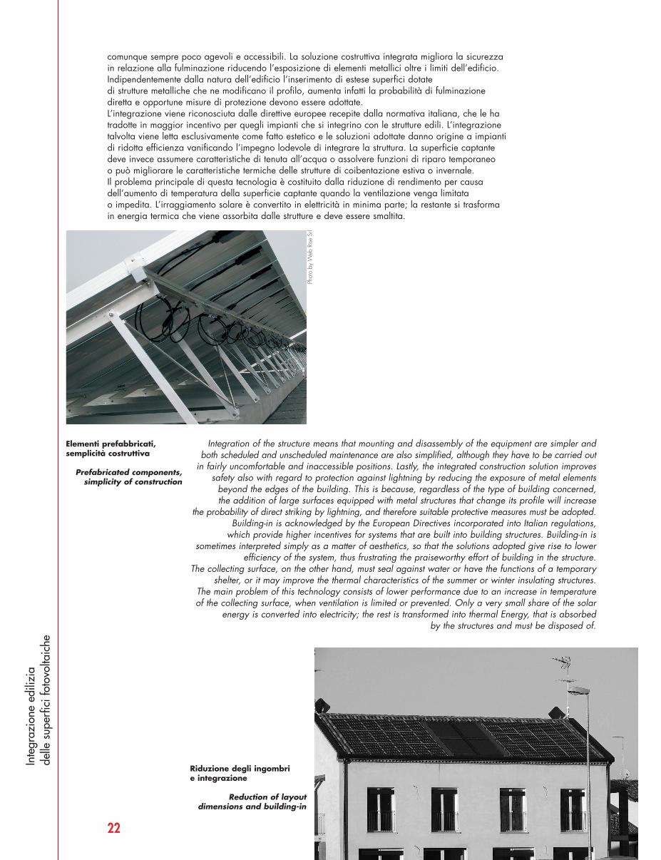
Elementi prefabbricati,semplicità costruttiva
Prefabricated components,simplicity of construction
Riduzione degli ingombri e integrazione
Reduction of layoutdimensions and building-in
comunque sempre poco agevoli e accessibili. La soluzione costruttiva integrata migliora la sicurezza in relazione alla fulminazione riducendo l’esposizione di elementi metallici oltre i limiti dell’edificio.Indipendentemente dalla natura dell’edificio l’inserimento di estese superfici dotate di strutture metalliche che ne modificano il profilo, aumenta infatti la probabilità di fulminazionediretta e opportune misure di protezione devono essere adottate. L’integrazione viene riconosciuta dalle direttive europee recepite dalla normativa italiana, che le hatradotte in maggior incentivo per quegli impianti che si integrino con le strutture edili. L’integrazionetalvolta viene letta esclusivamente come fatto estetico e le soluzioni adottate danno origine a impiantidi ridotta efficienza vanificando l’impegno lodevole di integrare la struttura. La superficie captantedeve invece assumere caratteristiche di tenuta all’acqua o assolvere funzioni di riparo temporaneo o può migliorare le caratteristiche termiche delle strutture di coibentazione estiva o invernale.Il problema principale di questa tecnologia è costituito dalla riduzione di rendimento per causadell’aumento di temperatura della superficie captante quando la ventilazione venga limitata o impedita. L’irraggiamento solare è convertito in elettricità in minima parte; la restante si trasforma in energia termica che viene assorbita dalle strutture e deve essere smaltita.
Integration of the structure means that mounting and disassembly of the equipment are simpler andboth scheduled and unscheduled maintenance are also simplified, although they have to be carried out
in fairly uncomfortable and inaccessible positions. Lastly, the integrated construction solution improvessafety also with regard to protection against lightning by reducing the exposure of metal elements
beyond the edges of the building. This is because, regardless of the type of building concerned, the addition of large surfaces equipped with metal structures that change its profile will increase
the probability of direct striking by lightning, and therefore suitable protective measures must be adopted. Building-in is acknowledged by the European Directives incorporated into Italian regulations,
which provide higher incentives for systems that are built into building structures. Building-in issometimes interpreted simply as a matter of aesthetics, so that the solutions adopted give rise to lower
efficiency of the system, thus frustrating the praiseworthy effort of building in the structure. The collecting surface, on the other hand, must seal against water or have the functions of a temporary
shelter, or it may improve the thermal characteristics of the summer or winter insulating structures.The main problem of this technology consists of lower performance due to an increase in temperatureof the collecting surface, when ventilation is limited or prevented. Only a very small share of the solar
energy is converted into electricity; the rest is transformed into thermal Energy, that is absorbed by the structures and must be disposed of.
Phot
o by
Web
Rise
Srl
20_25 FISHER_FOTOVOLTAICHE 10-11-2008 14:07 Pagina 22
23
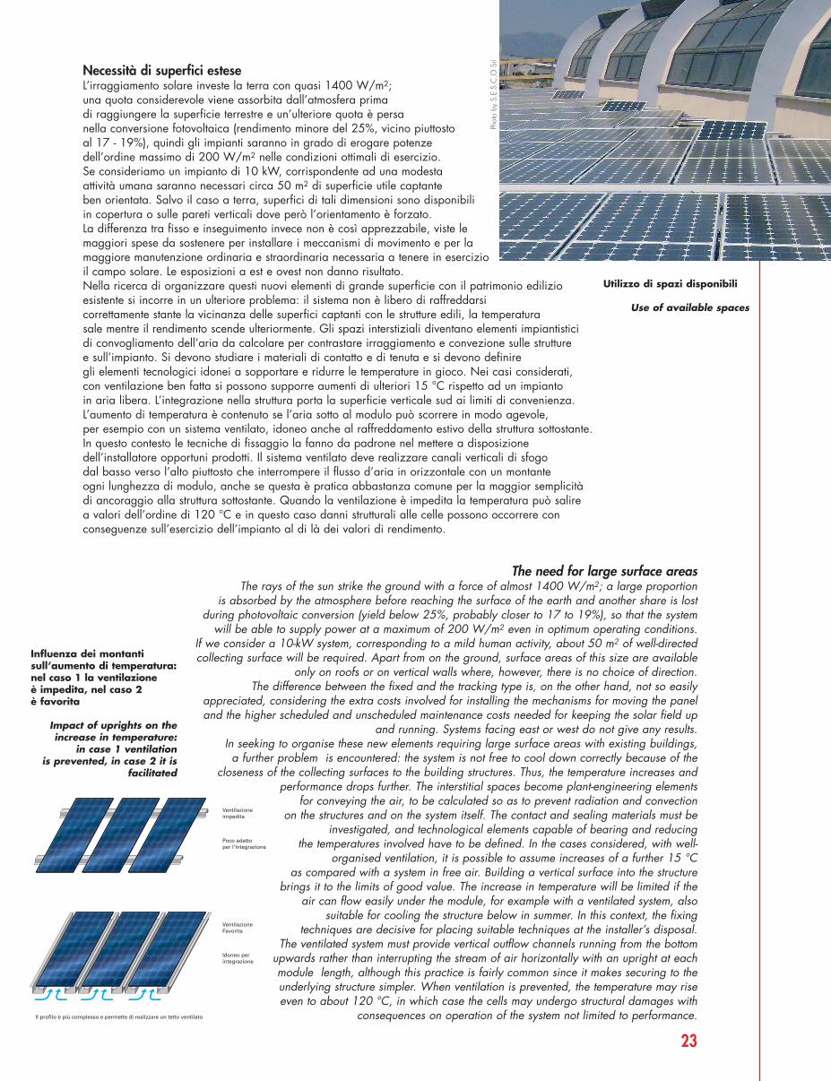
Necessità di superfici esteseL’irraggiamento solare investe la terra con quasi 1400 W/m2; una quota considerevole viene assorbita dall’atmosfera prima di raggiungere la superficie terrestre e un’ulteriore quota è persa nella conversione fotovoltaica (rendimento minore del 25%, vicino piuttosto al 17 - 19%), quindi gli impianti saranno in grado di erogare potenze dell’ordine massimo di 200 W/m2 nelle condizioni ottimali di esercizio. Se consideriamo un impianto di 10 kW, corrispondente ad una modesta attività umana saranno necessari circa 50 m2 di superficie utile captante ben orientata. Salvo il caso a terra, superfici di tali dimensioni sono disponibili in copertura o sulle pareti verticali dove però l’orientamento è forzato. La differenza tra fisso e inseguimento invece non è così apprezzabile, viste lemaggiori spese da sostenere per installare i meccanismi di movimento e per lamaggiore manutenzione ordinaria e straordinaria necessaria a tenere in esercizioil campo solare. Le esposizioni a est e ovest non danno risultato.Nella ricerca di organizzare questi nuovi elementi di grande superficie con il patrimonio edilizioesistente si incorre in un ulteriore problema: il sistema non è libero di raffreddarsi correttamente stante la vicinanza delle superfici captanti con le strutture edili, la temperatura sale mentre il rendimento scende ulteriormente. Gli spazi interstiziali diventano elementi impiantistici di convogliamento dell’aria da calcolare per contrastare irraggiamento e convezione sulle strutture e sull’impianto. Si devono studiare i materiali di contatto e di tenuta e si devono definire gli elementi tecnologici idonei a sopportare e ridurre le temperature in gioco. Nei casi considerati,con ventilazione ben fatta si possono supporre aumenti di ulteriori 15 °C rispetto ad un impianto in aria libera. L’integrazione nella struttura porta la superficie verticale sud ai limiti di convenienza.L’aumento di temperatura è contenuto se l’aria sotto al modulo può scorrere in modo agevole, per esempio con un sistema ventilato, idoneo anche al raffreddamento estivo della struttura sottostante.In questo contesto le tecniche di fissaggio la fanno da padrone nel mettere a disposizionedell’installatore opportuni prodotti. Il sistema ventilato deve realizzare canali verticali di sfogo dal basso verso l’alto piuttosto che interrompere il flusso d’aria in orizzontale con un montante ogni lunghezza di modulo, anche se questa è pratica abbastanza comune per la maggior semplicitàdi ancoraggio alla struttura sottostante. Quando la ventilazione è impedita la temperatura può salire a valori dell’ordine di 120 °C e in questo caso danni strutturali alle celle possono occorrere conconseguenze sull’esercizio dell’impianto al di là dei valori di rendimento.
The need for large surface areasThe rays of the sun strike the ground with a force of almost 1400 W/m2; a large proportion
is absorbed by the atmosphere before reaching the surface of the earth and another share is lostduring photovoltaic conversion (yield below 25%, probably closer to 17 to 19%), so that the system
will be able to supply power at a maximum of 200 W/m2 even in optimum operating conditions. If we consider a 10-kW system, corresponding to a mild human activity, about 50 m2 of well-directedcollecting surface will be required. Apart from on the ground, surface areas of this size are available
only on roofs or on vertical walls where, however, there is no choice of direction. The difference between the fixed and the tracking type is, on the other hand, not so easily
appreciated, considering the extra costs involved for installing the mechanisms for moving the paneland the higher scheduled and unscheduled maintenance costs needed for keeping the solar field up
and running. Systems facing east or west do not give any results.In seeking to organise these new elements requiring large surface areas with existing buildings, a further problem is encountered: the system is not free to cool down correctly because of the
closeness of the collecting surfaces to the building structures. Thus, the temperature increases andperformance drops further. The interstitial spaces become plant-engineering elements
for conveying the air, to be calculated so as to prevent radiation and convection on the structures and on the system itself. The contact and sealing materials must be
investigated, and technological elements capable of bearing and reducing the temperatures involved have to be defined. In the cases considered, with well-
organised ventilation, it is possible to assume increases of a further 15 °C as compared with a system in free air. Building a vertical surface into the structure
brings it to the limits of good value. The increase in temperature will be limited if theair can flow easily under the module, for example with a ventilated system, also
suitable for cooling the structure below in summer. In this context, the fixingtechniques are decisive for placing suitable techniques at the installer’s disposal.
The ventilated system must provide vertical outflow channels running from the bottomupwards rather than interrupting the stream of air horizontally with an upright at eachmodule length, although this practice is fairly common since it makes securing to theunderlying structure simpler. When ventilation is prevented, the temperature may riseeven to about 120 °C, in which case the cells may undergo structural damages with
consequences on operation of the system not limited to performance.
Utilizzo di spazi disponibili
Use of available spaces
Ventilazioneimpedita
VentilazioneFavorita
Poco adattoper l’integrazione
Idoneo perintegrazione
Il profilo è più complesso e permette di realizzare un tetto ventilato
Influenza dei montantisull’aumento di temperatura:nel caso 1 la ventilazioneè impedita, nel caso 2 è favorita
Impact of uprights on theincrease in temperature:
in case 1 ventilation is prevented, in case 2 it is
facilitated
Phot
o by
S.E
.S.C
.O S
rl
20_25 FISHER_FOTOVOLTAICHE 10-11-2008 14:07 Pagina 23
24
Inte
graz
ione
edi
lizia
delle
sup
erfic
i fot
ovol
taic
heDisponibilità di superfici orizzontali e verticali: un occhio di riguardo agli edificiL’edilizia moderna ha perso nella cultura propria i concetti principali di orientamento degli edifici,sopperendo a tale mancanza attraverso impianti elettromeccanici di comfort tra cui si annoveranoquelli di illuminazione, di riscaldamento e raffrescamento, quelli di ventilazione; perfino il movimentodi serramenti e schermature può essere automatizzato. L’orientamento delle superfici acquistanuovamente importanza, per dare spazio ai sistemi che devono erogare energia agli impianti di comfort stessi. Si tratta di trovare ampie superfici idonee e dedicate, a disposizione e in vicinanzadei luoghi di impiego per il miglior uso dell’energia.La superficie a terra è già stata utilizzata dagli edifici, ma una pressoché uguale superficie si trova in copertura. Si dovrà tener conto di ombre riportate, di piani di sviluppo e di distanze di rispetto tra edifici. Occorre guardare in primo luogo alle nuove costruzioni, senza abbandonare l’esistente,
spesso mal orientato e non idoneo per accogliere i sistemi moderni. Sono comuni le soluzioni di montaggio in appoggio ai manti di copertura in tegole, che ottengono parziale integrazione architettonica,ma che consentono di mantenere un’elevata ventilazione e quindi corrispondenti basse temperature di esercizio e alte rese. Le coperture offrono superfici vaste e se orizzontali o sub orizzontali si prestano a soluzioni orientate in modo ottimale o quasi.
Availability of horizontal and vertical surfaces: looking at buildingsThe concept of making a building face in a specific direction no longer exists in the modern
building industry. This shortcoming is made up for by electromechanical systems for lighting, heating and cooling and ventilation.
Even the movements of windows and blinds can be automated. The direction in which surfaces face becomes important again in terms of making room
for the equipment for supplying power to these systems. It is a matter of finding largesuitable and dedicated surfaces to place at disposal close to the place of use so
that the power can be exploited in the best possible way.The surface area on the ground has already been used for buildings, but an almost equally largesurface area is available on the roof. Shadows, heights and distances to be maintained between
the buildings have to be taken into account. It will be necessary, first of all to look at the new buildings, without ignoring the existing ones, although they are often not facing in the best
direction and are not suitable for installing modern systems.Resting the system on the curved tiles is a common solution giving rise to partial building
into the architecture yet retaining good ventilation and therefore corresponding low operatingtemperatures and high yields. Roofs provide vast surfaces and if they are horizontal or sub-horizontal
they enable the system to be faced in the best possible direction or almost.
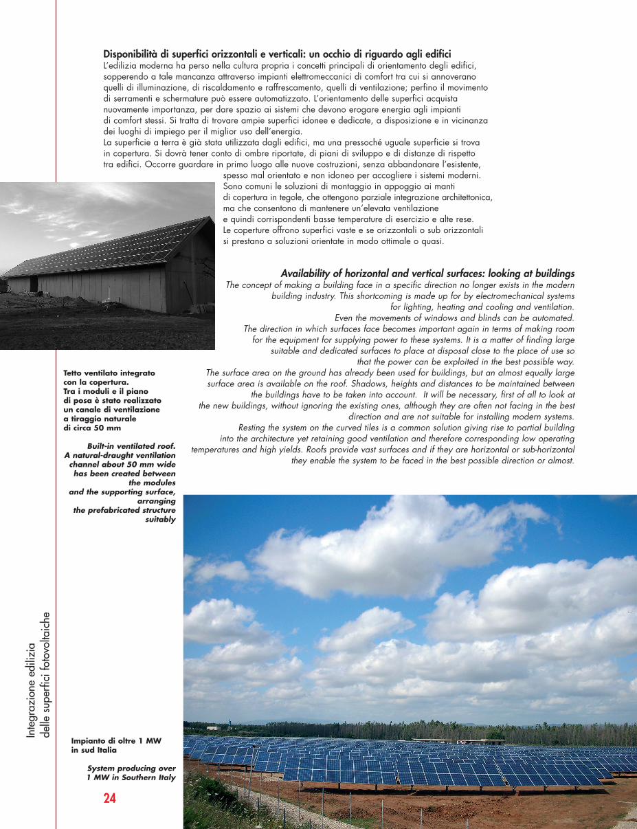
Tetto ventilato integrato con la copertura. Tra i moduli e il piano di posa è stato realizzato un canale di ventilazione a tiraggio naturale di circa 50 mm
Built-in ventilated roof. A natural-draught ventilationchannel about 50 mm wide has been created between
the modules and the supporting surface,
arranging the prefabricated structure
suitably
Impianto di oltre 1 MW in sud Italia
System producing over 1 MW in Southern Italy
20_25 FISHER_FOTOVOLTAICHE 10-11-2008 14:07 Pagina 24
25
Evoluzione dell’impianto integratoÈ necessario rivedere gli edifici nella loro collocazione urbanistica, nella struttura edile e nell’assegnazione degli spazi tecnici in relazione alla tecnologia applicata. Il coordinamentointerdisciplinare diventa ancora più importante per identificare nuove soluzioni di integrazione:pensiline di protezione per persone e automobili nei parcheggi e aree di sosta; protezione di negozie attività commerciali in luogo di drappi e tendaggi; tetti ventilati di coperture ecc.
Evolution of built-in systemsIt is necessary to consider the buildings in their town-planning context and with regard to their
building structure and the areas allocated for technical uses with reference to the technology used.Interdisciplinary co-ordination becomes even more important for identifying new solutions for buildingsystems into buildings: shelters for protecting people and cars in parking areas and so on; replacing
shop awnings and blinds, ventilated roofs etc.
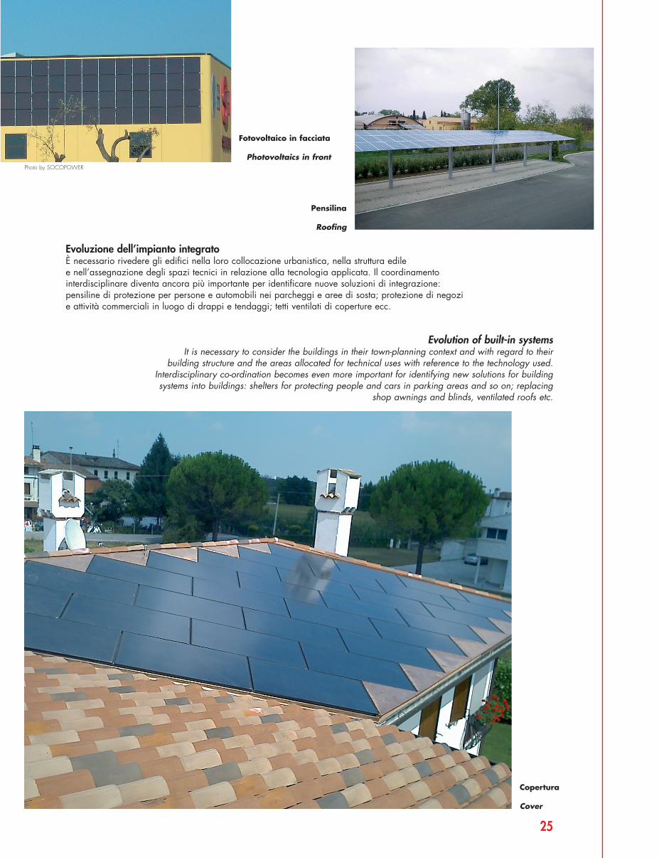
Copertura
Cover
Fotovoltaico in facciata
Photovoltaics in front
Pensilina
Roofing
Photo by SOCOPOWER
20_25 FISHER_FOTOVOLTAICHE 10-11-2008 14:07 Pagina 25