
IMER INTERNATIONAL S.p.A. - PSM Plant & Tool … · 1CABLE D' ACIER 2CROCHET 3TAMBOUR ... 9 ENDSC...
5
IMER INTERNATIONAL S.p.A. ET 300 - - 2 Fig. 1 1 9 780 2 3 380 4 5 6 7 8 10 11 12 330 260 1 FUNE ACCIAIO 2 GANCIO 3 TAMBURO 4 MOTORE ELETTRICO AUTOFRENENTE 5 QUADRO ELETTRICO 6 TELAIO 7 RUOTINA 8 FRENO DI STAZIONAMENTO 9 LEVA FINECORSA SUPERIORE 10 CONTRAPPESO 11 RIDUTTORE 12 PULSANTIERA 13 LEVA FINECORSA DISCESA (TELECOMANDO) 1 CABLE D' ACIER 2 CROCHET 3 TAMBOUR 4 MOTEUR ELECTRIQUE AUTOFREINANT 5 TABLEAU ELECTRIQUE 6 CHÂSSIS 7 ROUE 8 FREIN 9 LEVIER FIN DE COURSE SUPERIEURE 10 LEST 11 REDUCTEUR 12 BOITE Á BOUTONS 13 LEVIER DE FIN DE COURSE DE DESCENTE (TELECOMMANDE) 1 ROPE 2 HOOK 3 DRUM 4 ELECTRIC BRAKE MOTOR 5 ELECTRIC PANEL 6 FRAME 7 WHEEL 8 HAND BRAKE 9 UP LIMIT SWITCH LEVER 10 COUNTERWEGHT 11 GEAR BOX 12 PENDANT CONTROL 13 DOWN POSITION CONTROL LEVER (REMOTE CONTROL) 1 DRAHTSEIL 2 HAKEN 3 SEILTROMMEL 4 BREMSMOTOR 5 GEHÄUSEDECKEL 6 AUSLEGER 7 RAD 8 BREMSE 9 ENDSCHALTERHEBEL 10 SEILGEWICHT 11 GETRIIEBEDECKELDICHTUNG 12 HÄNGETASTER 13 HEBEL UNTERER ENDSCHALTER (FERNSTEUERUNG) 1 CABLE DE ACERO 2 GANCHO 3 TAMBOR 4 MOTOR ELÉCTRICO AUTOFRENANTE 5 CUADRO ELÉCTRICO 6 BASTIDOR 7 RUEDA 8 FRENO 9 PALANCA FINAL DE CARRERA SUPERIOR 10 CONTRAPESO 11 REDUCTOR 12 BOTONERA 13 PALANCA FIN DE CARRERA DE BAJADA (TELEMANDO) Particolare attenzione deve essere fatta alle avvertenze contrassegnate con questo simbolo : Il faut prêter une attention toute particulière aux notes précédées de ce symbole: Special attention must be given to warnings with this symbol: Lesen Sie die mit diesem Symbol bezeichneten Abschnitte mit besonderer Aufmerksamkeit: Se tiene que prestar una atención especial a las indicaciones marcadas con el signo: DATI TECNICI DONNEES TECHNIQUES TECHNICAL DATA TECHNISCHE DATEN DATO TECNICOS Portata max Débit maxi. Max capacity Tragfähigkeit Capacidad máx. kg 300 Velocità media di sollevamento Vitesse de levage Lifting speed Hubgeschwindigkeit Velocidad de elevación m / 1' 19 Altezza max di lavoro Hauteur maxi. de travail Max working height Max. Hubhöhe Altura máx. de trabajo m 25 Alimentazione Alimentation Nom. voltage Spannung Alimentación V / Hz 230 / 50 Potenza motore Puissance moteur Motor power Motorleistung Potencia motor Kw 1,1 Giri motore Tours moteur R.P.M. Motordrehzahl Revoluciones motor n° / 1' 1320 Assorbimento Absorption Nom. current Stromaufnahme Consumo A 12 Tipo di servizio Type de service Service type Betriebsart Tipo de servicio S3 50 % Livello di emissione sonora -- LwA (EN ISO 3744) Niveau d'emission sonore -- LwA (EN ISO 3744) Level of noise emission -- LwA (EN ISO 3744) Schallpegel der verschiedenen -- LwA (EN ISO 3744) Nivel de emisiòn sonora -- LwA (EN ISO 3744) dB 83 Livello di pressione sonora -- LpA -- 1,5 m Niveau de puissance sonore -- LpA -- 1,5 m Level of noise pressure -- LpA -- 1,5m Gemessenem schalleistungspegel -- LpA -- 1,5 m Nivel de presiòn sonora -- LpA -- 1,5 m dB <72 Peso della macchina Poids de la machine Hoist weight Maschinengewicht Peso de la máquina kg 50 Ingombro per l'imballo Encombrement pour l'emballage Packing dimensions Abmessungen mit Verpackung Dimensiones para el embalaje mm 820x350x440 Norme di progetto Normes de projet Design standards Konstruktionsnormen Normas del proyecto DPR 459 del 24.7.96 D.N°92-765/766/767 et L233-84 S.I N°3073 of 30/11/92 9.GSGV von 12.05.93 R.D. 1435/92 FEM 1.001 UNI-ISO 4301-4308-2408 UNI 7670-9466 EN 60204-1 o 13
Transcript of IMER INTERNATIONAL S.p.A. - PSM Plant & Tool … · 1CABLE D' ACIER 2CROCHET 3TAMBOUR ... 9 ENDSC...

IMER INTERNATIONAL S.p.A.ET 300
- -2
Fig. 1
1
9
780
2
3
380
4
5
67
8
10
11
12
330
260
1 FUNE ACCIAIO2 GANCIO3 TAMBURO4 MOTORE ELETTRICO AUTOFRENENTE5 QUADRO ELETTRICO6 TELAIO7 RUOTINA8 FRENO DI STAZIONAMENTO9 LEVA FINECORSA SUPERIORE
10 CONTRAPPESO11 RIDUTTORE12 PULSANTIERA13 LEVA FINECORSA DISCESA
(TELECOMANDO)
1 CABLE D' ACIER2 CROCHET3 TAMBOUR4 MOTEUR ELECTRIQUE AUTOFREINANT5 TABLEAU ELECTRIQUE6 CHÂSSIS7 ROUE
8 FREIN9 LEVIER FIN DE COURSE SUPERIEURE
10 LEST11 REDUCTEUR12 BOITE Á BOUTONS13 LEVIER DE FIN DE COURSE DE DESCENTE
(TELECOMMANDE)
1 ROPE2 HOOK3 DRUM4 ELECTRIC BRAKE MOTOR5 ELECTRIC PANEL6 FRAME7 WHEEL8 HAND BRAKE9 UP LIMIT SWITCH LEVER10 COUNTERWEGHT11 GEAR BOX12 PENDANT CONTROL13 DOWN POSITION CONTROL LEVER
(REMOTE CONTROL)
1 DRAHTSEIL2 HAKEN3 SEILTROMMEL4 BREMSMOTOR5 GEHÄUSEDECKEL6 AUSLEGER7 RAD8 BREMSE9 ENDSCHALTERHEBEL10 SEILGEWICHT11 GETRIIEBEDECKELDICHTUNG12 HÄNGETASTER13 HEBEL UNTERER ENDSCHALTER
(FERNSTEUERUNG)
1 CABLE DE ACERO 2 GANCHO3 TAMBOR4 MOTOR ELÉCTRICO AUTOFRENANTE5 CUADRO ELÉCTRICO6 BASTIDOR7 RUEDA8 FRENO9 PALANCA FINAL DE CARRERA SUPERIOR
10 CONTRAPESO11 REDUCTOR12 BOTONERA13 PALANCA FIN DE CARRERA DE BAJADA
(TELEMANDO)
Particolare attenzione deve essere fatta alle avvertenze contrassegnate con questo simbolo :Il faut prêter une attention toute particulière aux notes précédées de ce symbole:Special attention must be given to warnings with this symbol:Lesen Sie die mit diesem Symbol bezeichneten Abschnitte mit besonderer Aufmerksamkeit:Se tiene que prestar una atención especial a las indicaciones marcadas con el signo:
DATI TECNICIDONNEES
TECHNIQUESTECHNICAL DATA TECHNISCHE DATEN DATO TECNICOS
Portata max Débit maxi. Max capacity Tragfähigkeit Capacidad máx. kg 300Velocità media disollevamento
Vitesse de levage Lifting speed Hubgeschwindigkeit Velocidad de elevación m / 1' 19
Altezza max di lavoro Hauteur maxi. de travail Max working height Max. Hubhöhe Altura máx. de trabajo m 25Alimentazione Alimentation Nom. voltage Spannung Alimentación V / Hz 230 / 50Potenza motore Puissance moteur Motor power Motorleistung Potencia motor Kw 1,1Giri motore Tours moteur R.P.M. Motordrehzahl Revoluciones motor n° / 1' 1320Assorbimento Absorption Nom. current Stromaufnahme Consumo A 12Tipo di servizio Type de service Service type Betriebsart Tipo de servicio S3 50 %Livello di emissionesonora -- LwA(EN ISO 3744)
Niveau d'emissionsonore -- LwA(EN ISO 3744)
Level of noise emission-- LwA(EN ISO 3744)
Schallpegel derverschiedenen -- LwA(EN ISO 3744)
Nivel de emisiònsonora -- LwA(EN ISO 3744)
dB 83
Livello di pressionesonora -- LpA -- 1,5 m
Niveau de puissancesonore -- LpA -- 1,5 m
Level of noise pressure-- LpA -- 1,5m
Gemessenemschalleistungspegel --LpA -- 1,5 m
Nivel de presiòn sonora-- LpA -- 1,5 m
dB <72
Peso della macchina Poids de la machine Hoist weight Maschinengewicht Peso de la máquina kg 50
Ingombro per l'imballoEncombrement pourl'emballage
Packing dimensionsAbmessungen mitVerpackung
Dimensiones para elembalaje
mm 820x350x440
Norme di progetto Normes de projet Design standards Konstruktionsnormen Normas del proyecto
DPR 459del 24.7.96
D.N°92-765/766/767 etL233-84
S.I N°3073 of 30/11/92 9.GSGV von 12.05.93 R.D. 1435/92
FEM 1.001 UNI-ISO 4301-4308-2408 UNI 7670-9466 EN 60204-1
o
13
IMER INTERNATIONAL S.p.A.ET 300
- -11
GBGB
Dear ClientCongratulations on choosing the IMER winch, the reliable andinnovative result of years of experience.
WORKING IN SAFETYTo work in complete safety, read the following instructionscarefully before installing the machine.
This OPERATION AND MAINTENANCE manual must be kept onsite by the person in charge, e.g. the site foreman, and must alwaysbe available for consultation.The manual is to be considered an integral part of the machine andmust be kept for future reference (EN 292/2) until the machine isdisposed of. If it is damaged or lost, a replacement copy may berequested from the manufacturer.The manual contains important information regarding site preparation,installation, operation, maintenance, and ordering spare parts.Nevertheless, the installer and the operator must both have adequateexperience and knowledge of the machine prior to use.To guarantee the complete safety of the operator, safe operation andlong life of equipment, follow the instructions in this manual carefully,and observe all safety standards currently in force for the preventionof accidents at work (use of suitable footwear and clothing, hard hats,safety harnesses, proper installation of railings around drops, etc.).
It is strictly forbidden to carry out any form of modificationto the steel structure, working parts of the machine or thegantry structure.
IMER INTERNATIONAL declines all responsibility for non-compliancewith laws and standards governing the use of lifting equipment, inparticular; improper use, defective power supply, lack of maintenance,unauthorised modifications, tampering with or damage to part or allof the equipment, and partial or total failure to observe the instructionscontained in this manual.
IMER INTERNATIONAL reserves the right to modify thecharacteristics of the hoist and/or the contents of thismanual without any obligation to update previousmachines or manuals.
1. GENERAL DESCRIPTIONATTENTION: Use of lifting equipment requires care andskill. The machine must be operated by skilled and properlyinstructed personnel only.1) The machine is designed to lift materials only and foruse in building construction sites.2) Carrying persons and/or animals is prohibited.3) The machine must not be used in potentially explosiveatmospheres or underground.
The machine consists of (fig. 1):- frame (ref. 6) with hand brake (ref. 8).- Drum (ref. 3) fitted to reduction gearbox shaft (ref. 11), steel rope(ref. 1) lift hook (ref. 2) and counterweight (ref. 10);- Gearmotor consisting of an electric brake motor (ref. 4) and oilreduction gearbox (ref. 11). - Electrical system (5) with 1 m pendant control with threepushbuttons (12)- Up position control lever (9).- 3-button low voltage pendant control with 25 m lead (on remotecontrol versions), with down position control lever (13).
2. IMER HOIST SUPPORT STRUCTURE
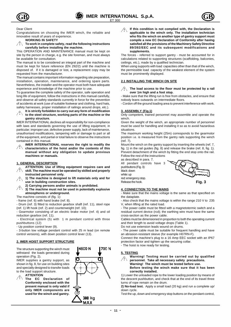
The structure supporting the winch mustwithstand the loads generated duringoperation (Fig. 2).IMER supplies a gantry support, asshown in fig. 8, for use on building sitesand specially designed to transfer loadsto the load support structure.
ATTENTIONThe EC Declaration ofConformity enclosed with thepresent manual is only valid ifonly IMER components areused for the winch and gantry.
If this condition is not complied with, the Declaration isapplicable to the winch only. The installation technicianwho fits the winch on another type of gantry support mustcompile a new EC Declaration of Conformity after havingsatisfied all the provisions of the Machinery Safety Directive89/392/EEC and its subsequent modifications andsupplements.
The forces - referred to support gantry - must be accounted for incalculations related to supporting structures (scaffolding, balconies,ceilings, etc.), made by a qualified technician.When using supports with load capacities other than that of the winch,the permissible load capacity of the weakest element of the systemmust be prominently displayed.
2.1 INSTALLING THE WINCH ON SITE
The load access to the floor must be protected by a railover 1m high and a foot stop.
- Make sure that the lifting run is free from obstacles, and ensure thatnobody leans outwards on intermediate floors.- Cordon off the ground loading area to prevent interference with work.
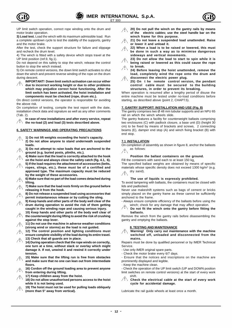
3. ASSEMBLY (Fig.1)Only competent, trained personnel may assemble and operate thewinch.Given the weight of the winch, an appropriate number of personnelmust be used for handling and installing it so as to avoid hazardoussituations.The maximum working height (25m) corresponds to the gearmotorposition i.e. is measured from the gantry rails supporting the winch(ref. 7).Mount the winch on the gantry support by inserting the wheels (ref. 7,fig. 1) in the rail guides (fig. 8) and release the brake (ref. 8, fig. 1).Prevent detachment of the winch by fitting the end stop onto the rail.Follow the rest of the instructionsas described in para. 7.All pendant controls have 3pushbuttons (Fig. 3):black: downwhite: upred: emergency stop.Release the hook.
4. CONNECTION TO THE MAINS- Make sure that the mains voltage is the same as that specified onthe dataplate.- Also check that the mains voltage is within the range 210 V to 235V, when lifting at the rated load.- The power cable must be fitted with a magnetotermic switch and aresidual current device (rcd); the earthing wire must have the samecross-section as the power cable.Cables must be dimensioned in proportion to both the operating currentand their length to avoid voltage drops (Table 1).Do not use extension leads wound on drums.- The power cable must be suitable for frequent handling and havean abrasion-resistant sleeve (for example H07RN-F).Connect the machine’s plug to a 16 Amp EEC socket with an IP67protection factor and tighten up the securing collar.- The hoist is now ready for testing.
5. TESTINGWarning! Testing must be carried out by qualifiedpersonnel. Take all necessary safety precautions.Warning! The winch must be tested before use.Before testing the winch make sure that it has beencorrectly installed.
1) Lower the unloaded rope to the lower loading position by means ofthe descent pushbutton, and check that at the end of its travel threeturns of rope remain on the drum.2) No-load test. Apply a small load (20 kg) and run a complete up/down cycle.Test the up, down and emergency stop buttons on the pendant control,
Fig. 2
Fig. 3
IMER INTERNATIONAL S.p.A.ET 300
- -12
GB GB
UP limit switch operation, correct rope winding onto the drum andmotor brake operation.3) Load test. Load the winch with its maximum admissible load. Runa complete up/down cycle to test the stability of the supports, gantryand the motor brake.After the test, check the support structure for failure and slippageand recheck the drum level.4) The winch is fitted with a safety device which stops travel at theUP limit position (ref.9, fig.1).Do not depend on this safety to stop the winch; release the controlbutton to stop the winch instead.5) On remote control versions, the down limit switch activates to shutdown the winch and prevent reverse winding of the rope on the drumduring descent.
IMPORTANT! Down limit switch activation can occur eitherdue to incorrect working height or due to other problemswhich may prejudice correct hoist functioning. After thelimit switch has been activated, the hoist installation andcomponents must be checked (rope, drum etc.).
On direct control versions, the operator is responsible for avoidingthe above risk.On completion of testing, compile the test report with the date,installation check data and signature as well as any other comments(Tab. 2).
In case of new installations and after every service, repeatthe no-load (2) and load (3) tests described above.
6. SAFETY WARNINGS AND OPERATING PRECAUTIONS
1) Do not lift weights exceeding the hoist’s capacity.2) Do not allow anyone to stand underneath suspendedloads.3) Do not attempt to raise loads that are anchored to theground (e.g. buried posts, plinths, etc.).4) Make sure that the load is correctly attached to the hookon the hoist and always close the safety catch (fig. 4.1, 6).5) If the load requires the attachment of accessories (belts,ropes, slings, etc.), these must be of a certified andapproved type. The maximum capacity must be reducedby the weight of these accessories.6) Make sure that no part of the load comes detached duringlifting.7) Make sure that the load rests firmly on the ground beforereleasing it from the hook.8) Do not release a suspended load using accessories thatpermit instantaneous release or by cutting the sling.9) Keep hands and other parts of the body well clear of thedrum during operation to avoid the risk of them gettingcaught in the winding rope and causing serious injury.10) Keep hands and other parts of the body well clear ofthe counterweight during lifting to avoid the risk of crushingagainst the stop lever.11) Do not use the machine in adverse weather conditions(strong wind or storms) as the load is not guided.12) The control position and lighting conditions mustensure complete visibility of the load during its entire travel.13) Check that all guards are in place.14) During operation check that the rope winds on correctly,one turn at a time, without slack or overlay which mightdamage it. If not, unwind it and rewind it correctly undertension.15) Make sure that the lifting run is free from obstaclesand make sure that no one can lean out from intermediatefloors.16) Cordon off the ground loading area to prevent anyonefrom entering during lifting.17) Keep children away from the hoist.18) Do not allow unauthorised persons access to the hoistwhile it is not being used.19) The hoist must not be used for pulling loads obliquely(more than 5° away from vertical).
20) Do not pull the winch on the gantry rails by meansof the electric cables; use the steel handle bar on thewinch frame for this purpose.21) Do not leave a suspended load unattended. Raiseor lower it and unload it.22) When a load is to be raised or lowered, this mustbe done in such a way as to minimise dangeroussideways and vertical movements.23) Do not allow the load to start to spin while it isbeing raised or lowered as this could cause the ropeto break.24) Before leaving the hoist unattended, remove theload, completely wind the rope onto the drum anddisconnect the electric power plug.25) On t he remote control version, the pendantcontrol cable must be secured to the buildingstructures, in order to prevent its breaking.
When operation is resumed after a lengthy period of disuse theentire machine must be tested under no-load conditions beforestarting, as described above (point 2, CHAPT.5).
7. GANTRY SUPPORT: INSTALLATION AND USE (Fig. 8)The gantry comprises two Ø 48 mm tubular supports and an NPU 65rail on which the winch wheels slide.The gantry features a facility for counterweight ballasts comprisingtwo enclosures (C) with padlock closure, a base unit (D) (height 30cm) to be fixed by means of brackets and screws, 2 connectingbeams (E), damper end stop (A) and winch fixing bracket (B) withend stop.
7.1 INSTALLATIONOn completion of assembly as shown in figure 8, anchor the ballasts
as follows:
Position the ballast containers on the ground.Fill the containers with sand each to at least 150 kg.The specified ballast weights are obtained by means of specificmaterials whose specific density does not exceed 1300 kg/m3 (e.g.
dry sand).
The use of liquids is expressly prohibited.To avoid tampering with ballasts, the containers must be closed withlids and padlocked.Never use makeshift systems such as bags of cement or brickssimply placed on the gantry frame as these cannot be sufficientlyanchored to the frame.- Always ensure complete efficiency of the ballasts before using the
winch; check for any damage that may affect operation.Do not fit the winch onto the gantry before fitting theballasts.
Remove the winch from the gantry rails before disassembling thegantry and emptying the ballasts.
8. TESTING AND MAINTENANCEWarning! Only carry out maintenance with the machineswitched off, unloaded and disconnected from themains.
Repairs must be done by qualified personnel or by IMER TechnicalService.- Use only IMER original spare parts.- Check the motor brake every 6/7 days.- Ensure that the notices and inscriptions on the machine areprominently displayed and legible.- Keep the machine clean.- Check the operation of the UP limit switch (UP and DOWN positionlimit switches on remote control versions) at the start of every work
shift.Check the electrical cable at the start of every workcycle for accidental damage.
Lubricate the rail guide wheels at least once a month.

IMER INTERNATIONAL S.p.A.ET 300
- -13
GB GB
8.1 STEEL ROPEOnly use new ropes as specified below, complete with certificate ofconformity and identification.External diameter mm 5Type 133 wires (19x7) anti-rotationDirection of lay r.h.Strand strength (N/mm²) 1960Minimum breaking strain (kN) 16,07Length (m) 26Surface treatment galvanised, greasedThe IMER reference code is given in the spare parts table.
8.1.1 REPLACING THE ROPE
The rope must be replaced by aqualified service technician.Remove the hook (4) by unscrewingbolt (5) (fig. 4.1).Remove the clamp (1), push on thewedge (2) and extract the rope fromthe block (3).The drum is fitted with a device whichensures that 2 turns of rope arealways wound on even when therope is unwound to its limit. Thisstops the rope attachment frombeing over-forced.
The rope must be attached in this way. Completely unwind the rope.Remove it from inside the drum through the hole and slot. Insert thenew rope in the hole and thread it through the slot in the drum tube.Tighten the clamp at the end, leaving about 1 cm of rope free (fig.4.2), and pull the rope until the clamp comes into contact with theinner wall of the drum.Wind on two complete turns keeping the rope in contact with thedrum (Fig. 4.3).On the second turn passthe rope under the hookinside the drum slot (Fig.4.4).Tension the rope forgood contact with thedrum surface.Now wind on the rope inadjacent turns, one layerat a time.Insert the wire rope intothe counterweight and the block (Fig. 4.5).Pass the rope back through the counterweight and the block.Insert the wedge between the block and the rope.Pull the rope to tighten all components. Now lock the rope with a U-clamp so that the flat part remains in contact with the lifting section ofthe rope. Leaving about 1 cm of rope free.Fit the hook to the block and tighten the bolt and locknut.Check that the UP limit switch operates when the counterweighttouches the lever.Run the load test described in paragraph 5 and note down in Table 2the fact that the rope has been changed.
8.1.2 PERIODIC CHECKS
Visually check the condition of the rope every day andwhenever it is subjected to abnormal strain (twisting,bending, kinks or abrasion).
Replace the rope when defective as indicated in fig.9.Inspect the entire rope carefully every three months and in particularthe ends; note the results in the chart (Table 2) which must be keptby the site foreman.Replace the rope at least once a year.
8.2 ADJUSTING THE MOTOR BRAKE (Fig. 5)
The brake is of the no-power engagement type.If its braking power is reduced a qualified technician must check thedevice and adjust it.
Warning!! Before servicing the brake make sure that thewinch is not loaded and that the brake’s power supply isdisconnected.
Remove fan cover (A), and adjust the airgap “d” between magnet (B) and brake disk(C) by means of a feeler gauge. The gap(d) must be 0.4 mm.Measurement should be taken at threepoints in order to check that the disc isperfectly parallel to the magnet. Slide thefeeler gauge lightly backwards andforwards. If the air gap is too wide, redu-ce it by tightening nut “D” with a hexwrench. Check distance “d” several times.If the air gap is too small, increase it byunscrewing nut “D”.Once the air gap has been correctlyadjusted, refit cover “A”.To check braking power, after carrying outthe adjustment, repeatedly test brakingaction under full load conditions.
8.3 GEARBOX LUBRICATION
The gearbox unit must not develop oil leaks. Leaks may indicatedamage to the aluminium casing. In this case, reseal or replace thecasing.
Check the gearbox oil level through the sight glass beforeevery start up or long storage. Refill as required via therelative cap on the gearbox. The oil should be changedevery 2000 hours. Use gear oil with ISO VG 460 viscosityat 40°C.Used oil is classed as special waste. As such, it must bedisposed of in accordance with established legislation.
8.4 ELECTRICAL SYSTEMCheck the condition of the pendant control case and replace with theIMER spare part if necessary.
Fig. 4.1
Fig. 4.4
Fig. 4.3
Fig. 4.2
Fig. 4.5
Fig. 5
IMER INTERNATIONAL S.p.A.ET 300
- -14
GBGB
9. DISMANTLING
Remove all loads from the winch hook.Wind the steel rope completely onto the drum.
Disassemble the fixing bracket (ref. B, fig. 8) and removethe winch from the gantry guides. Carry out this operationbefore emptying the ballasts.
10. TRANSPORT AND STORAGE
Do not leave the installed winch unattended without havingdisconnected the electrical power line and wound the rope completelyonto the drum.When storing the machine for a long period of time, protect it fromweather conditions.During transport, protect the machine from blows and crushing toavoid compromising its functionality and mechanical strength.
11. SCRAPPING
In the event of scrapping, proceed as follows:a) drain off all oil by means of the relative plug.b) Separate all plastic and electrical components (cables,
pendant control etc.)c) Divide all metal components according to type (steel,
aluminium etc.)On completion of the above, dispose of all components at authorisedwaste disposal centres in compliance with current legislation.
Respect the environment; certain parts can be harmful topersons or to the environment.
12. TROUBLESHOOTING
13. PROCEDURE IN CASE OF FAULT WITH LOAD SUSPENDED
- If possible remove the load from the nearest level, then dismountthe winch and service it.- If this is not possible, use another lifting machine (with adequateload capacity) from higher up and suspend the faulty winch both atthe load and at the winch attachment point.Lift the faulty winch slowly off its fitting, then lower the entire load tothe ground.- DO NOT adjust the motor brake with the load suspended as it wouldbe uncontrollable.- DO NOT try to service the machine with the load suspended.
14. NOISE LEVEL AT THE OPERATOR’S EAR
The level Lp(A) given in the TECHNICAL DATA chart corresponds tothe weighted equivalent sound pressure level on scale A of EuropeanDirective 98/37. This level is measured with no load, at the operator’shead in the working position 1.5 metres away from the instrument,considering the different working conditions.
FAULT CAUSE SOLUTIONThe machine doesnot lift or lower oncommand
Emergency stop buttonengaged
Turn to disengage
No power to machine Check mains cable
Plug not inserted Plug in
Power board cutouttripped
Reset the switch
Sliding not smoothon gantry rails
Frame wheelslubrication insufficient
Lubrificate wheels
IF THE FAULT PERSISTS Contact IMER TechnicalService


![Hobsbawm Sobre Togliatti LRB[1]](https://static.fdocumenti.com/doc/165x107/577cda131a28ab9e78a4ce42/hobsbawm-sobre-togliatti-lrb1.jpg)