HR - brevinifluidpower.ie · HR Motore orbitale Orbital motor 1 - SERIE / SERIES S Versione Base...
27
MOTORI ORBITALI HYDRAULIC MOTOR SERIES HR F/1 COD. 05-0087-A37
Transcript of HR - brevinifluidpower.ie · HR Motore orbitale Orbital motor 1 - SERIE / SERIES S Versione Base...
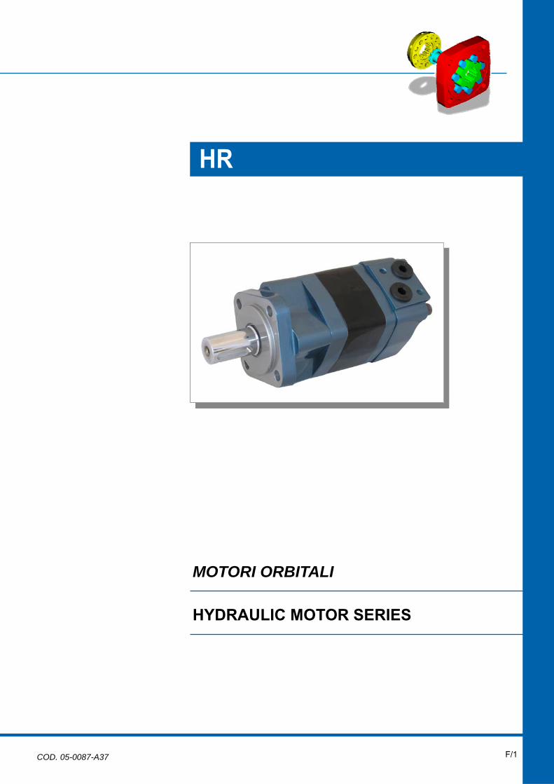
MOTORI ORBITALI
HYDRAULIC MOTOR SERIES
HR
F/1 COD. 05-0087-A37
F/2 orbital
R
orbitalorbital
R
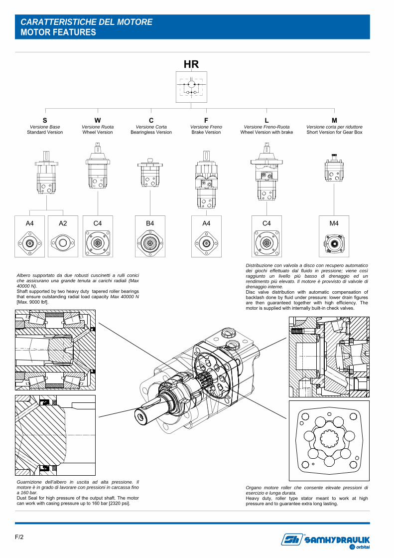
CARATTERISTICHE DEL MOTORE MOTOR FEATURES
HR
S Versione Base
Standard Version
Distribuzione con valvola a disco con recupero automatico dei giochi effettuato dal fluido in pressione; viene così raggiunto un livello più basso di drenaggio ed un rendimento più elevato. Il motore è provvisto di valvole di drenaggio interne. Disc valve distribution with automatic compensation of backlash done by fluid under pressure: lower drain figures are then guaranteed together with high efficiency. The motor is supplied with internally built-in check valves.
Albero supportato da due robusti cuscinetti a rulli conici che assicurano una grande tenuta ai carichi radiali (Max 40000 N). Shaft supported by two heavy duty tapered roller bearings that ensure outstanding radial load capacity Max 40000 N [Max. 9000 lbf].
Guarnizione dell’albero in uscita ad alta pressione. Il motore è in grado di lavorare con pressioni in carcassa fino a 160 bar. Dust Seal for high pressure of the output shaft. The motor can work with casing pressure up to 160 bar [2320 psi].
Organo motore roller che consente elevate pressioni di esercizio e lunga durata. Heavy duty, roller type stator meant to work at high pressure and to guarantee extra long lasting.
W Versione Ruota Wheel Version
C Versione Corta
Bearingless Version
F Versione Freno Brake Version
L Versione Freno-Ruota
Wheel Version with brake
M Versione corta per riduttore Short Version for Gear Box
A2 A4 C4 B4 A4 C4 M4

F/3 orbital
R
orbitalorbital
R
CARATTERISTICHE TECNICHE TECHNICAL SPECIFICATIONS
Motore Motor
Cilindrata Displacement
cm3/giro [in3/rev]
Max. pressione in ingresso
Max. input pressure bar [psi]
Pressione diff. max. Max. differential
pressure bar [psi]
Coppia max.* Max. torque*
Nm [lbf·ft]
Portata max. Max. flow
l/min [U.S. gpm]
Velocità max. Max. speed
[rpm]
Potenza max. Max. power
kW [hp]
HR 080 80.4 [4.9]
Cont Int1)
Peak2)
210 [3045] 310 [4495] 310 [4495]
Cont Int1)
Peak2)
205 [2972] 310 [4495] 310 [4495]
Cont Int1)
235 [173] 345 [254]
Cont Int1)
75 [19.8] 80 [21.1]
Cont Int1)
932 995
Cont Int1)
23 [30.8] 36 [48.2]
HR 100 100 [6.1]
Cont Int1)
Peak2)
210 [3045] 310 [4495] 310 [4495]
Cont Int1)
Peak2)
205 [2972] 310 [4495] 310 [4495]
Cont Int1)
295 [217] 445 [328]
Cont Int1)
75 [19.8] 95 [25]
Cont Int1)
750 950
Cont Int1)
23.1 [30.9] 44.2 [59.2]
HR 130 125.7 [7.66]
Cont Int1)
Peak2)
210 [3045] 310 [4495] 310 [4495]
Cont Int1)
Peak2)
205 [2972] 310 [4495] 310 [4495]
Cont Int1)
375 [276] 545 [401]
Cont Int1)
75 [19.8] 95 [25]
Cont Int1)
596.5 755.5
Cont Int1)
23.4 [31.3] 43.1 [57.7]
HR 160 160 [9.76]
Cont Int1)
Peak2)
210 [3045] 310 [4495] 310 [4495]
Cont Int1)
Peak2)
205 [2972] 260 [3770] 310 [4495]
Cont Int1)
465 [342] 570 [420]
Cont Int1)
75 [19.8] 95 [25]
Cont Int1)
468.5 593.5
Cont Int1)
18.2 [24.3] 22.5 [30.1]
HR 200 200 [12.2]
Cont Int1)
Peak2)
210 [3045] 310 [4495] 310 [4495]
Cont Int1)
Peak2)
205 [2972] 260 [3770] 310 [4495]
Cont Int1)
580 [427] 670 [494]
Cont Int1)
75 [19.8] 95 [25]
Cont Int1)
375 475
Cont Int1)
15.2 [20.3] 22.5 [30.1]
HR 250 250 [15.25]
Cont Int1)
Peak2)
210 [3045] 310 [4495] 310 [4495]
Cont Int1)
Peak2)
205 [2972] 260 [3770] 310 [4495]
Cont Int1)
710 [523] 820 [604]
Cont Int1)
75 [19.8] 95 [25]
Cont Int1)
300 380
Cont Int1)
14.2 [19] 19.5 [26.1]
HR 315 314.5 [19.18]
Cont Int1)
Peak2)
210 [3045] 310 [4495] 310 [4495]
Cont Int1)
Peak2)
205 [2972] 240 [3480] 310 [4495]
Cont Int1)
885 [652] 960 [707]
Cont Int1)
75 [19.8] 95 [25]
Cont Int1)
238.5 302
Cont Int1)
11 [14.7] 19.5 [26.1]
HR 400 393 [23.97]
Cont Int1)
Peak2)
210 [3045] 310 [4495] 310 [4495]
Cont Int1)
Peak2)
155 [2247] 190 [2755] 225 [3250]
Cont Int1)
860 [633] 980 [722]
Cont Int1)
75 [19.8] 95 [25]
Cont Int1)
190 241
Cont Int1)
11 [14.7] 13 [17.4]
1) Le condizioni intermittenti non devono durare più del 10% di ogni minuto. Intermittent duty must not exceed 10% each minute.
ALBERO CILINDRICO CL254 CL254 CYLINDRICAL SHAFT
ALBERO SCANALATO SE250 SE250 SPLINED SHAFT
* Coppia max. ammissibile per tipo d’albero * Max. admissible torque for shaft type
Nm [lbf·ft]
Cont 300 [221] Cont 360 [265]
Int1) 410 [302] Int1) 450 [332]
1) Le condizioni intermittenti non devono durare più del 10% di ogni minuto. Intermittent duty must not exceed 10% each minute.
2) Le condizioni di picco non devono durare più del 1% di ogni minuto. Peak duty must not exceed 1% each minute.
* Per i motori con gli alberi riportati nella tabella sottostante la coppia massima ammissibile è:
* For motors with the shafts in the table below the Max. admis-sible torque is reduced as follows:
HR 080 HR 100 HR 130 HR 160 HR 200 HR 250 HR 315 HR 400
Pressione max avviamento a vuoto Max starting pressure with no load
bar [psi]
11 [159]
10 [145]
10 [145]
8 [116]
8 [116]
8 [116]
8 [116]
8 [116]
Coppia min. di spunto (A press. diff. max) Min. starting torque (At. Max ∆p)
Nm [lbf·ft]
Cont. 180 [133] Int. 270 [199]
Cont. 230 [169] Int. 340 [250]
Cont. 300 [221] Int. 420 [309]
Cont. 370 [272] Int. 440 [324]
Cont. 465 [343] Int. 522 [385]
Cont. 568 [419] Int. 640 [472]
Cont. 700 [516] Int. 760 [560]
Cont. 680 [501] Int. 775 [571]
F/4 orbital
R
orbitalorbital
R
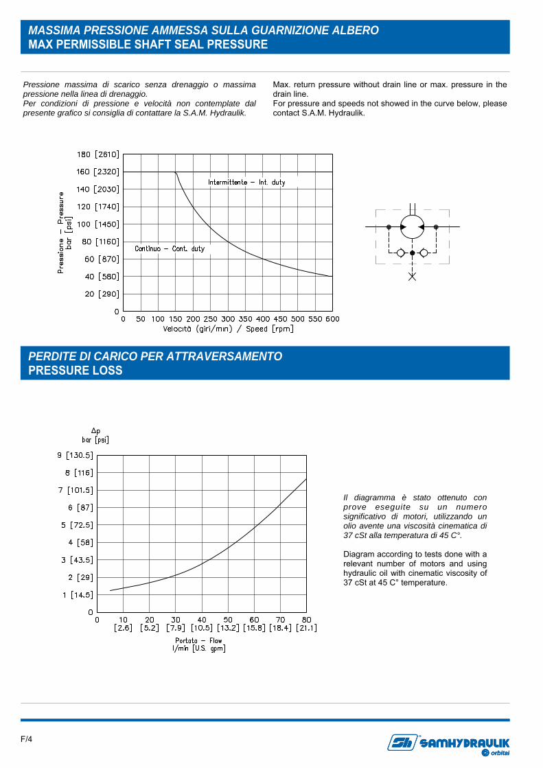
MASSIMA PRESSIONE AMMESSA SULLA GUARNIZIONE ALBERO MAX PERMISSIBLE SHAFT SEAL PRESSURE
Pressione massima di scarico senza drenaggio o massima pressione nella linea di drenaggio. Per condizioni di pressione e velocità non contemplate dal presente grafico si consiglia di contattare la S.A.M. Hydraulik.
Max. return pressure without drain line or max. pressure in the drain line. For pressure and speeds not showed in the curve below, please contact S.A.M. Hydraulik.
PERDITE DI CARICO PER ATTRAVERSAMENTO PRESSURE LOSS
Il diagramma è stato ottenuto con prove eseguite su un numero significativo di motori, utilizzando un olio avente una viscosità cinematica di 37 cSt alla temperatura di 45 C°. Diagram according to tests done with a relevant number of motors and using hydraulic oil with cinematic viscosity of 37 cSt at 45 C° temperature.
F/5 orbital
R
orbitalorbital
R
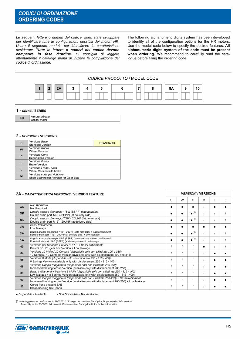
CODICI DI ORDINAZIONE ORDERING CODES
CODICE PRODOTTO / MODEL CODE
HR Motore orbitale Orbital motor
1 - SERIE / SERIES
S Versione Base Standard Version STANDARD
W Versione Ruota Wheel Version
C Versione Corta Bearingless Version
F Versione Freno Brake Version
L Versione Freno-Ruota Wheel Version with brake
M Versione corta per riduttore Short Bearingless Version for Gear Box
2 - VERSIONI / VERSIONS
2
3
7
6
8
8A
10
9
1
4
5 2A
Le seguenti lettere o numeri del codice, sono state sviluppate per identificare tutte le configurazioni possibili dei motori HR. Usare il seguente modulo per identificare le caratteristiche desiderate. Tutte le lettere o numeri del codice devono comparire in fase d’ordine. Si consiglia di leggere attentamente il catalogo prima di iniziare la compilazione del codice di ordinazione.
The following alphanumeric digits system has been developed to identify all of the configuration options for the HR motors. Use the model code below to specify the desired features. All alphanumeric digits system of the code must be present when ordering. We recommend to carefully read the cata-logue before filling the ordering code.
S W C M F L
XX Non Richiesta Not Required ● ● ● / ● ●
OK Doppio attacco drenaggio 1/4 G (BSPP) (lato mandata) Double drain port 1/4 G (BSPP) (at delivery side) ● ● ●(1) / / /
SK Doppio attacco drenaggio 7/16” - 20UNF (lato mandata) Double drain port 7/16” - 20UNF (at delivery side) ● ● ●(1) / / /
LW Bassi trafilamenti Low leakage ● ● ● ● ● ●
SW Doppio attacco drenaggio 7/16” - 20UNF (lato mandata) + Bassi trafilamenti Double drain port 7/16” - 20UNF (at delivery side) + Low leakage ● ● ●(1) / / /
KW Doppio attacco drenaggio 1/4 G (BSPP) (lato mandata) + Bassi trafilamenti Double drain port 1/4 G (BSPP) (at delivery side) + Low leakage ● ● ●(1) / / /
03 Versione per Riduttore Brevini SDU31 + Bassi trafilamenti Brevini SDU31 gear box Version + Low leakage / / / ● / /
04 Versione 12 Molle / 10 Contatti (disponibile solo con cilindrata 100 e 315) 12 Springs / 10 Contacts Version (available only with displacement 100 and 315) / / / / ● ●
05 Versione 8 Molle (disponibile solo con cilindrata 250 - 315 - 400) 8 Springs Version (available only with displacement 250 - 315 - 400) / / / / ● ●
06 Versione Coppia maggiorata (disponibile solo con cilindrata 200-250) Increased braking torque Version (available only with displacement 200-250) / / / / ● ●
08 Bassi trafilamenti + Versione 8 Molle (disponibile solo con cilindrata 250 - 315 - 400) Low leakage + 8 Springs Version (available only with displacement 250 - 315 - 400) / / / / ● ●
09 Versione Coppia maggiorata (disponibile solo con cilindrata 200-250) + Bassi trafilamenti Increased braking torque Version (available only with displacement 200-250) + Low leakage / / / / ● ●
10 Corpo freno attacchi SAE Brake housing SAE ports / / / / ● ●
VERSIONI / VERSIONS
● Disponibile - Available / Non Disponibile - Not Available
2A - CARATTERISTICA VERSIONE / VERSION FEATURE
(1) Montaggio come da documento M-052611. Si prega di contattare Samhydraulik per ulteriori informazioni. Assembly as the M-052611 document. Please contact Samhydraulik for further information.

F/6 orbital
R
orbitalorbital
R
080 80.4 cm3/giro [4.9 in3/rev]
100 100 cm3/giro [6.1 in3/rev]
130 125.7 cm3/giro [7.66 in3/rev]
160 160 cm3/giro [9.7 in3/rev]
200 200 cm3/giro [12.2 in3/rev]
250 250 cm3/giro [15.2 in3/rev]
315 314.5 cm3/giro [19.18 in3/rev]
400 393 cm3/giro [23.97 in3/rev]
3 - CILINDRATA / DISPLACEMENT
VERSIONI / VERSIONS
S W C M F L
M09 Attacchi 1/2 G BSPP (32x22) 1/2 G BSPP (32x22) Main Ports STANDARD ● ● ● ● ● ●
S09 Attacchi 7/8" - 14 UNF (32x22) 7/8" - 14 UNF (32x22) Main Ports ● ● ● / ● ●
L09 Attacchi Laterali 1" 1/16 - 12 UN 1" 1/16 - 12 UN (Main Ports Positioned 180° apart) ● ● ● / ● ●
F09 ● ● ● / ● ●
R09 Attacchi Frontali 7/8" - 14 UNF 7/8" - 14 UNF (End Main Ports)
A Richiesta Upon Request ● ● ● ● ● ●
Attacchi Frontali 1" 1/16 - 12 UN 1" 1/16 - 12 UN (End Main Ports)
5 - ATTACCHI / MAIN PORTS
Per le dimensioni vedere Pag. F/17 For the dimensions see Pag. F/17
● Disponibile - Available / Non Disponibile - Not Available
VERSIONI / VERSIONS S W C M F L
A4 4 Fori (Ø 82.5 mm) 4 Bolt [Ø 3.248 in] ● / / / ● /
A2 SAE A 2 Fori SAE A 2 Bolt ● / / / ○ /
B4 ISO 4 Fori (Ø 100 mm) ISO 4 Bolt [Ø 3.937 in] / / ● / / /
C4 ISO 4 Fori (Ø 125 mm) ISO 4 Bolt [Ø 4.921 in] / ● / / / ●
M4 Flangia corta per riduttore Short flange for Gear Box / / / ● / /
4 - FLANGIA / FLANGE
● Disponibile - Available / Non Disponibile - Not Available ○ A Richiesta - Upon Request
2
3
7
6
8
8A
10
9
1
4
5 2A
F/7 orbital
R
orbitalorbital
R
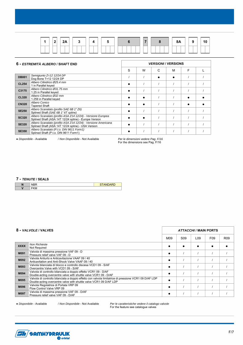
N NBR STANDARD V FKM
7 - TENUTE / SEALS
VERSIONI / VERSIONS
S W C M F L
DB001 Semigiunto Z=12 12/24 DP Dog Bone T=12 12/24 DP / / ● ● / /
CL254 Albero Cilindrico Ø25.4 mm 1 in Parallel keyed ● / / / / /
C3175 Albero Cilindrico Ø31.75 mm 1.25 in Parallel keyed ● / / / / /
CL320 Albero Cilindrico Ø32 mm 1.259 in Parallel keyed ● ● / / ● ●
CN320 Albero Conico Tapered Shaft ● ● / / ● ●
SE250 Albero Scanalato (profilo SAE 6B 1” Z6) Splined Shaft (SAE 6B 1” 6T spline) ● / / / / /
SC320 Albero Scanalato (profilo ASA Z14 12/24) - Versione Europea Splined Shaft (ASA 14T 12/24 spline) - Europe Version ● ● / / / /
SE320 Albero Scanalato (profilo ASA Z14 12/24) - Versione Americana Splined Shaft (ASA 14T 12/24 spline) - USA Version ● / / / / /
SE350 Albero Scanalato (P.t.o. DIN 9611 Form1) Splined Shaft (P.t.o. DIN 9611 Form1) ● / / / / /
6 - ESTREMITÀ ALBERO / SHAFT END
● Disponibile - Available / Non Disponibile - Not Available Per le dimensioni vedere Pag. F/16 For the dimensions see Pag. F/16
M09 S09 L09 F09 R09
XXXX Non Richieste Not Required ● ● ● ● ●
M091 Valvola di massima pressione VAF 09 - D Pressure relief valve VAF 09 - D ● / / / /
M092 Valvola Antiurto e Anticavitazione VAAF 09 / 40 Anticavitation and Anti-Shock Valve VAAF 09 / 40 ● / / / /
M093 Valvola bilanciata di blocco e controllo discesa VCD1 09 - S/AF Overcentre Valve with VCD1 09 - S/AF ● / / / /
M094 Valvola di controllo bilanciata a doppio effetto VCR1 09 - D/AF Double-acting overcentre valve with shuttle valve VCR1 09 - D/AF ● / / / /
M095 Valvola di controllo bilanciata a doppio effetto con valvola limitatrice di pressione VCR1 09 D/AF LDP Double-acting overcentre valve with shuttle valve VCR1 09 D/AF LDP ● / / / /
M096 Valvola Regolatrice di Portata VRP 09 Flow Control Valve VRP 09 ● / / / /
ATTACCHI / MAIN PORTS
M097 Valvola di massima pressione VAF 09 - D/AF Pressure relief valve VAF 09 - D/AF ● / / / /
Per le caratteristiche vedere il catalogo valvole For the feature see catalogue valves
● Disponibile - Available / Non Disponibile - Not Available
8 - VALVOLE / VALVES
2
3
7
6
8
8A
10
9
1
4
5 2A
F/8 orbital
R
orbitalorbital
R
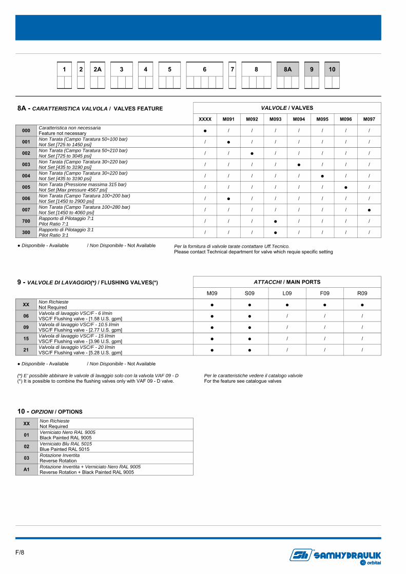
XX Non Richieste Not Required
01 Verniciato Nero RAL 9005 Black Painted RAL 9005
02 Verniciato Blu RAL 5015 Blue Painted RAL 5015
03 Rotazione Invertita Reverse Rotation
A1 Rotazione Invertita + Verniciato Nero RAL 9005 Reverse Rotation + Black Painted RAL 9005
10 - OPZIONI / OPTIONS
2
3
7
6
8
8A
10
9
1
4
5 2A
XXXX M091 M092 M093 M094 M095 M096 M097
000 Caratteristica non necessaria Feature not necessary ● / / / / / / /
001 Non Tarata (Campo Taratura 50÷100 bar) Not Set [725 to 1450 psi] / ● / / / / / /
002 Non Tarata (Campo Taratura 50÷210 bar) Not Set [725 to 3045 psi] / / ● / / / / /
003 Non Tarata (Campo Taratura 30÷220 bar) Not Set [435 to 3190 psi] / / / / ● / / /
004 Non Tarata (Campo Taratura 30÷220 bar) Not Set [435 to 3190 psi] / / / / / ● / /
005 Non Tarata (Pressione massima 315 bar) Not Set [Max pressure 4567 psi] / / / / / / ● /
006 Non Tarata (Campo Taratura 100÷200 bar) Not Set [1450 to 2900 psi] / ● / / / / / /
007 Non Tarata (Campo Taratura 100÷280 bar) Not Set [1450 to 4060 psi] / / / / / / / ●
700 Rapporto di Pilotaggio 7:1 Pilot Ratio 7:1 / / / ● / / / /
300 Rapporto di Pilotaggio 3:1 Pilot Ratio 3:1 / / / ● / / / /
VALVOLE / VALVES
● Disponibile - Available / Non Disponibile - Not Available
8A - CARATTERISTICA VALVOLA / VALVES FEATURE
Per la fornitura di valvole tarate contattare Uff.Tecnico. Please contact Technical department for valve which requie specific setting
M09 S09 L09 F09 R09
XX Non Richieste Not Required ● ● ● ● ●
06 Valvola di lavaggio VSC/F - 6 l/min VSC/F Flushing valve - [1.58 U.S. gpm] ● ● / / /
09 Valvola di lavaggio VSC/F - 10.5 l/min VSC/F Flushing valve - [2.77 U.S. gpm] ● ● / / /
15 Valvola di lavaggio VSC/F - 15 l/min VSC/F Flushing valve - [3.96 U.S. gpm] ● ● / / /
21 Valvola di lavaggio VSC/F - 20 l/min VSC/F Flushing valve - [5.28 U.S. gpm] ● ● / / /
ATTACCHI / MAIN PORTS
● Disponibile - Available / Non Disponibile - Not Available
Per le caratteristiche vedere il catalogo valvole For the feature see catalogue valves
9 - VALVOLE DI LAVAGGIO(*) / FLUSHING VALVES(*)
(*) E’ possibile abbinare le valvole di lavaggio solo con la valvola VAF 09 - D (*) It is possible to combine the flushing valves only with VAF 09 - D valve.
F/9 orbital
R
orbitalorbital
R
DIMENSIONI E PESI DIMENSIONS AND WEIGHT
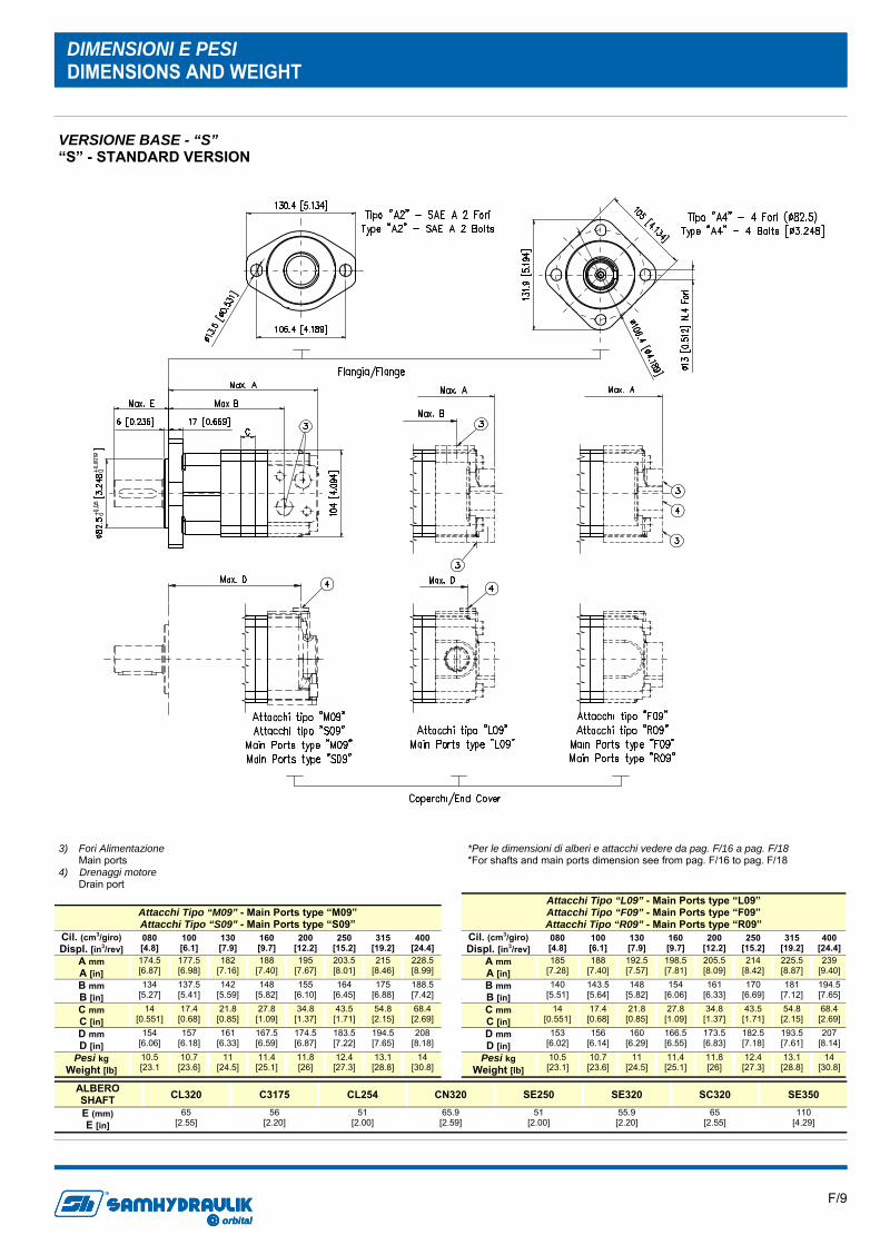
ALBERO SHAFT CL320 C3175 CL254 CN320 SE250 SE320 SC320
E (mm) E [in]
65 [2.55]
56 [2.20]
51 [2.00]
65.9 [2.59]
51 [2.00]
55.9 [2.20]
65 [2.55]
SE350 110
[4.29]
Attacchi Tipo “M09” - Main Ports type “M09” Attacchi Tipo “S09” - Main Ports type “S09”
Cil. (cm3/giro) Displ. [in3/rev]
080 [4.8]
100 [6.1]
130 [7.9]
160 [9.7]
200 [12.2]
250 [15.2]
315 [19.2]
400 [24.4]
A mm A [in]
174.5 [6.87]
177.5 [6.98]
182 [7.16]
188 [7.40]
195 [7.67]
203.5 [8.01]
215 [8.46]
228.5 [8.99]
B mm B [in]
134 [5.27]
137.5 [5.41]
142 [5.59]
148 [5.82]
155 [6.10]
164 [6.45]
175 [6.88]
188.5 [7.42]
C mm C [in]
14 [0.551]
17.4 [0.68]
21.8 [0.85]
27.8 [1.09]
34.8 [1.37]
43.5 [1.71]
54.8 [2.15]
68.4 [2.69]
D mm D [in]
154 [6.06]
157 [6.18]
161 [6.33]
167.5 [6.59]
174.5 [6.87]
183.5 [7.22]
194.5 [7.65]
208 [8.18]
Pesi kg Weight [lb]
10.5 [23.1
10.7 [23.6]
11 [24.5]
11.4 [25.1]
11.8 [26]
12.4 [27.3]
13.1 [28.8]
14 [30.8]
Attacchi Tipo “L09” - Main Ports type “L09” Attacchi Tipo “F09” - Main Ports type “F09” Attacchi Tipo “R09” - Main Ports type “R09”
Cil. (cm3/giro) Displ. [in3/rev]
080 [4.8]
100 [6.1]
130 [7.9]
160 [9.7]
200 [12.2]
250 [15.2]
315 [19.2]
400 [24.4]
A mm A [in]
185 [7.28]
188 [7.40]
192.5 [7.57]
198.5 [7.81]
205.5 [8.09]
214 [8.42]
225.5 [8.87]
239 [9.40]
B mm B [in]
140 [5.51]
143.5 [5.64]
148 [5.82]
154 [6.06]
161 [6.33]
170 [6.69]
181 [7.12]
194.5 [7.65]
C mm C [in]
14 [0.551]
17.4 [0.68]
21.8 [0.85]
27.8 [1.09]
34.8 [1.37]
43.5 [1.71]
54.8 [2.15]
68.4 [2.69]
D mm D [in]
153 [6.02]
156 [6.14]
160 [6.29]
166.5 [6.55]
173.5 [6.83]
182.5 [7.18]
193.5 [7.61]
207 [8.14]
Pesi kg Weight [lb]
10.5 [23.1]
10.7 [23.6]
11 [24.5]
11.4 [25.1]
11.8 [26]
12.4 [27.3]
13.1 [28.8]
14 [30.8]
VERSIONE BASE - “S” “S” - STANDARD VERSION
3) Fori Alimentazione Main ports 4) Drenaggi motore Drain port
*Per le dimensioni di alberi e attacchi vedere da pag. F/16 a pag. F/18 *For shafts and main ports dimension see from pag. F/16 to pag. F/18
F/10 orbital
R
orbitalorbital
R
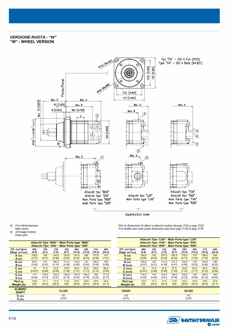
ALBERO SHAFT CL320 CN320
E mm E [in]
101 [3.97]
102 [4.01]
SC320 101
[3.97]
Attacchi Tipo “M09” - Main Ports type “M09” Attacchi Tipo “S09” - Main Ports type “S09”
Cil. (cm3/giro) Displ. [in3/rev]
080 [4.8]
100 [6.1]
130 [7.9]
160 [9.7]
200 [12.2]
250 [15.2]
315 [19.2]
400 [24.4]
A mm A [in]
136.5 [5.37]
140 [5.51]
144.5 [5.68]
150.5 [5.92]
157.5 [6.20]
166 [6.53]
177.5 [6.98]
191 [7.51]
B mm B [in]
97.5 [3.83]
101 [3.97]
105.3 [4.14]
111.3 [4.38]
118.3 [4.65]
127 [5.00]
138.5 [5.45]
152 [5.98]
C mm C [in]
14 [0.551]
17.4 [0.68]
21.8 [0.85]
27.8 [1.09]
34.8 [1.37]
43.5 [1.71]
54.8 [2.15]
68.4 [2.69]
D mm D [in]
117 [4.60]
120.5 [4.74]
124.8 [4.91]
130.8 [5.14]
137.8 [5.42]
146.5 [5.76]
158 [6.22]
171.5 [6.75]
Pesi kg Weight [lb]
10.9 [24]
11.1 [24.4]
11.5 [25.3]
11.8 [26]
12.2 [26.8]
12.9 [28.4]
13.6 [29.9]
14.4 [31.7]
Attacchi Tipo “L09” - Main Ports type “L09” Attacchi Tipo “F09” - Main Ports type “F09” Attacchi Tipo “R09” - Main Ports type “R09”
Cil. (cm3/giro) Displ. [in3/rev]
080 [4.8]
100 [6.1]
130 [7.9]
160 [9.7]
200 [12.2]
250 [15.2]
315 [19.2]
400 [24.4]
A mm A [in]
149.5 [5.88]
153 [6.02]
157.5 [6.20]
163.5 [6.43]
170.5 [6.71]
179 [7.04]
190.5 [7.50]
204 [8.03]
B mm B [inch]
103.5 [4.07]
107 [4.21]
111.3 [4.38]
117.3 [4.61]
124.3 [4.89]
133 [5.23]
144.5 [5.68]
158 [6.22]
C (mm) C [inch]
14 [0.551]
17.4 [0.68]
21.8 [0.85]
27.8 [1.09]
34.8 [1.37]
43.5 [1.71]
54.8 [2.15]
68.4 [2.69]
D (mm) D [inch]
114.5 [4.50]
118 [4.64]
122.3 [4.81]
128.3 [5.05]
135.5 [5.33]
144 [5.66]
155.5 [6.12]
169 [6.65]
Pesi (kg) Weight (lb)
10.9 [24]
11.1 [24.4]
11.5 [25.3]
11.8 [26]
12.2 [26.8]
12.9 [28.4]
13.6 [29.9]
14.4 [31.7]
VERSIONE RUOTA - “W” ”W” - WHEEL VERSION
3) Fori Alimentazione Main ports 4) Drenaggi motore Drain port
*Per le dimensioni di alberi e attacchi vedere da pag. F/16 a pag. F/18 *For shafts and main ports dimension see from pag. F/16 to pag. F/18
F/11 orbital
R
orbitalorbital
R
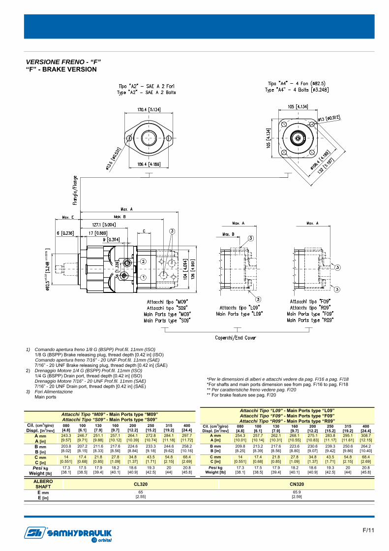
VERSIONE FRENO - “F” “F” - BRAKE VERSION
ALBERO SHAFT CL320 CN320
E mm E [in]
65 [2.55]
65.9 [2.59]
Attacchi Tipo “M09” - Main Ports type “M09” Attacchi Tipo “S09” - Main Ports type “S09”
Cil. (cm3/giro) Displ. [in3/rev]
080 [4.8]
100 [6.1]
130 [7.9]
160 [9.7]
200 [12.2]
250 [15.2]
315 [19.2]
400 [24.4]
A mm A [in]
243.3 [9.57]
246.7 [9.71]
251.1 [9.88]
257.1 [10.12]
264.1 [10.39]
272.8 [10.74]
284.1 [11.18]
297.7 [11.72]
B mm B [in]
203.8 [8.02]
207.2 [8.15]
211.6 [8.33]
217.6 [8.56]
224.6 [8.84]
233.3 [9.18]
244.6 [9.62]
258.2 [10.16]
C mm C [in]
14 [0.551]
17.4 [0.68]
21.8 [0.85]
27.8 [1.09]
34.8 [1.37]
43.5 [1.71]
54.8 [2.15]
68.4 [2.69]
Pesi kg Weight [lb]
17.3 [38.1]
17.5 [38.5]
17.9 [39.4]
18.2 [40.1]
18.6 [40.9]
19.3 [42.5]
20 [44]
20.8 [45.8]
Attacchi Tipo “L09” - Main Ports type “L09” Attacchi Tipo “F09” - Main Ports type “F09” Attacchi Tipo “R09” - Main Ports type “R09”
Cil. (cm3/giro) Displ. [in3/rev]
080 [4.8]
100 [6.1]
130 [7.9]
160 [9.7]
200 [12.2]
250 [15.2]
315 [19.2]
400 [24.4]
A mm A [in]
254.3 [10.01]
257.7 [10.14]
262.1 [10.31]
268.1 [10.55]
275.1 [10.83]
283.8 [11.17]
295.1 [11.61]
308.7 [12.15]
B mm B [in]
209.8 [8.25]
213.2 [8.39]
217.6 [8.56]
223.6 [8.80]
230.6 [9.07]
239.3 [9.42]
250.6 [9.86]
264.2 [10.40]
C mm C [in]
14 [0.551]
17.4 [0.68]
21.8 [0.85]
27.8 [1.09]
34.8 [1.37]
43.5 [1.71]
54.8 [2.15]
68.4 [2.69]
Pesi kg Weight [lb]
17.3 [38.1]
17.5 [38.5]
17.9 [39.4]
18.2 [40.1]
18.6 [40.9]
19.3 [42.5]
20 [44]
20.8 [45.8]
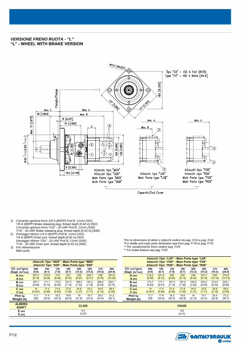
1) Comando apertura freno 1/8 G (BSPP) Prof.fil. 11mm (ISO) 1/8 G (BSPP) Brake releasing plug, thread depth [0.42 in] (ISO) Comando apertura freno 7/16” - 20 UNF Prof.fil. 11mm (SAE) 7/16” - 20 UNF Brake releasing plug, thread depth [0.42 in] (SAE) 2) Drenaggio Motore 1/4 G (BSPP) Prof.fil. 11mm (ISO) 1/4 G (BSPP) Drain port, thread depth [0.42 in] (ISO) Drenaggio Motore 7/16” - 20 UNF Prof.fil. 11mm (SAE) 7/16” - 20 UNF Drain port, thread depth [0.42 in] (SAE) 3) Fori Alimentazione Main ports
*Per le dimensioni di alberi e attacchi vedere da pag. F/16 a pag. F/18 *For shafts and main ports dimension see from pag. F/16 to pag. F/18 ** Per caratteristiche freno vedere pag. F/20 ** For brake feature see pag. F/20
F/12 orbital
R
orbitalorbital
R
ALBERO SHAFT CL320 CN320
E mm E [in]
101 [3.97]
102 [4.01]
Attacchi Tipo “M09” - Main Ports type “M09” Attacchi Tipo “S09” - Main Ports type “S09”
Cil. (cm3/giro) Displ. [in3/rev]
080 [4.8]
100 [6.1]
130 [7.9]
160 [9.7]
200 [12.2]
250 [15.2]
315 [19.2]
400 [24.4]
A mm A [in]
207.2 [8.15]
210.6 [8.29]
215 [8.46]
221 [8.70]
228 [8.97]
236.7 [9.31]
248 [9.76]
261.6 [10.29]
B mm B [in]
167.7 [6.60]
171.1 [6.73]
175.5 [6.90]
181.5 [7.14]
188.5 [7.42]
197.2 [7.76]
208.5 [8.20]
222.1 [8.74]
C mm C [in]
14 [0.551]
17.4 [0.68]
21.8 [0.85]
27.8 [1.09]
34.8 [1.37]
43.5 [1.71]
54.8 [2.15]
68.4 [2.69]
Pesi kg Weight [lb]
17.7 [39]
17.9 [39.4]
18.3 [40.3]
18.6 [40.9]
19 [41.8]
19.7 [43.4]
20.4 [44.9]
21.2 [46.7]
Attacchi Tipo “L09” - Main Ports type “L09” Attacchi Tipo “F09” - Main Ports type “F09” Attacchi Tipo “R09” - Main Ports type “R09”
Cil. (cm3/giro) Displ. [in3/rev]
080 [4.8]
100 [6.1]
130 [7.9]
160 [9.7]
200 [12.2]
250 [15.2]
315 [19.2]
400 [24.4]
A mm A [in]
218.2 [8.59]
221.6 [8.72]
226 [8.89]
232 [9.13]
239 [9.40]
247.7 [9.75]
259 [10.19]
272.6 [10.73]
B mm B [in]
173.7 [6.83]
177.1 [6.97]
181.5 [7.14]
187.5 [7.38]
194.5 [7.65]
203.2 [8.00]
214.5 [8.44]
228.1 [8.98]
C mm C [in]
14 [0.551]
17.4 [0.68]
21.8 [0.85]
27.8 [1.09]
34.8 [1.37]
43.5 [1.71]
54.8 [2.15]
68.4 [2.69]
Pesi kg Weight [lb]
17.7 [39]
17.9 [39.4]
18.3 [40.3]
18.6 [40.9]
19 [41.8]
19.7 [43.4]
20.4 [44.9]
21.2 [46.7]
VERSIONE FRENO RUOTA - “L” “L” - WHEEL WITH BRAKE VERSION
*Per le dimensioni di alberi e attacchi vedere da pag. F/16 a pag. F/18 *For shafts and main ports dimension see from pag. F/16 to pag. F/18 ** Per caratteristiche freno vedere pag. F/20 ** For brake feature see pag. F/20
1) Comando apertura freno 1/8 G (BSPP) Prof.fil. 11mm (ISO) 1/8 G (BSPP) Brake releasing plug, thread depth [0.42 in] (ISO) Comando apertura freno 7/16” - 20 UNF Prof.fil. 11mm (SAE) 7/16” - 20 UNF Brake releasing plug, thread depth [0.42 in] (SAE) 2) Drenaggio Motore 1/4 G (BSPP) Prof.fil. 11mm (ISO) 1/4 G (BSPP) Drain port, thread depth [0.42 in] (ISO) Drenaggio Motore 7/16” - 20 UNF Prof.fil. 11mm (SAE) 7/16” - 20 UNF Drain port, thread depth [0.42 in] (SAE) 3) Fori Alimentazione Main ports

F/13 orbital
R
orbitalorbital
R
Attacchi Tipo “M09” - Main Ports type “M09” Attacchi Tipo “S09” - Main Ports type “S09”
Cil. (cm3/giro) Displ. [in3/rev]
080 [4.8]
100 [6.1]
130 [7.9]
160 [9.7]
200 [12.2]
250 [15.2]
315 [19.2]
400 [24.4]
A mm A [in]
127.7 [5.02]
131 [5.15]
135.5 [5.33]
141.5 [5.57]
148.5 [5.84]
157.2 [6.18]
168.5 [6.63]
182 [7.16]
B mm B [in]
87.2 [3.43]
90.6 [3.56]
95 [3.74]
101 [3.97]
108 [4.25]
116.7 [4.59]
128 [5.03]
141.6 [5.57]
C mm C [in]
14 [0.551]
17.4 [0.68]
21.8 [0.85]
27.8 [1.09]
34.8 [1.37]
43.5 [1.71]
54.8 [2.15]
68.4 [2.69]
D mm D [in]
106.7 [4.20]
110 [4.33]
114.5 [4.50]
120.5 [4.74]
127.5 [5.01]
136.2 [5.36]
147.5 [5.80]
161 [6.33]
Pesi kg Weight (lb)
8 [17.6]
8.2 [18]
8.6 [18.9]
8.9 [19.6]
9.3 [20.4]
10 [22]
10.7 [23.5]
11.5 [25.3]
Attacchi Tipo “L09” - Main Ports type “L09” Attacchi Tipo “F09” - Main Ports type “F09” Attacchi Tipo “R09” - Main Ports type “R09”
Cil. (cm3/giro) Displ. [in3/rev]
080 [4.8]
100 [6.1]
130 [7.9]
160 [9.7]
200 [12.2]
250 [15.2]
315 [19.2]
400 [24.4]
A mm A [in]
140.7 [5.53]
144 [5.66]
149.5 [5.88]
154.5 [6.08]
161.5 [6.35]
170.2 [6.70]
181.5 [7.14]
195 [7.67]
B mm B [in]
93.2 [3.66]
96.6 [3.80]
101 [3.97]
107 [4.21]
114 [4.48]
122.7 [4.83]
134 [5.27]
147.6 [5.81]
C mm C [in]
14 [0.551]
17.4 [0.68]
21.8 [0.85]
27.8 [1.09]
34.8 [1.37]
43.5 [1.71]
54.8 [2.15]
68.4 [2.69]
D mm D [in]
104.2 [4.10]
107.5 [4.23]
112 [4.40]
118 [4.64]
125 [4.92]
133.7 [5.26]
145 [5.70]
158.5 [6.24]
Pesi kg Weight (lb)
8 [17.6]
8.2 [18]
8.6 [18.9]
8.9 [19.6]
9.3 [20.4]
10 [22]
10.7 [23.5]
11.5 [25.3]
VERSIONE CORTA - “C” “C” - BEARINGLESS VERSION
3) Fori Alimentazione Main ports 4) Drenaggi motore Drain port
*Per le dimensioni degli attacchi vedere da pag. F/17 a pag. F/18 ** Per la sede di accoppiamento vedere pag. F/15 *For main ports dimension see from pag. F/17 to pag. F/18 ** For interface drawing see pag. F/15
F/14 orbital
R
orbitalorbital
R
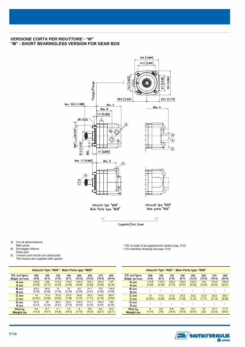
3) Fori di alimentazione Main ports 4) Drenaggio Motore Drain port 5) I motori sono forniti con distanziale The motors are supplied with spacer
VERSIONE CORTA PER RIDUTTORE - “M” “M” - SHORT BEARINGLESS VERSION FOR GEAR BOX
* Per la sede di accoppiamento vedere pag. F/15 * For interface drawing see pag. F/15
Attacchi Tipo “M09” - Main Ports type “M09”
Cil. (cm3/giro) Displ. [in3/rev]
080 [4.8]
100 [6.1]
130 [7.9]
160 [9.7]
200 [12.2]
250 [15.2]
315 [19.2]
400 [24.4]
A mm A [in]
102.6 [4.03]
106 [4.17]
110.4 [4.34]
116.4 [4.58]
123.4 [4.85]
132.1 [5.20]
143.4 [5.64]
157 [6.18]
B mm B [in]
62.2 [2.44]
65.6 [2.58]
70 [2.75]
76 [2.99]
83 [3.26]
91.7 [3.61]
103 [4.05]
116.6 [4.59]
C mm C [in]
14 [0.551]
17.4 [0.68]
21.8 [0.85]
27.8 [1.09]
34.8 [1.37]
43.5 [1.71]
54.8 [2.15]
68.4 [2.69]
D mm D [in]
81.6 [3.21]
85 [3.34]
89.4 [3.51]
95.4 [3.75]
102.4 [4.03]
111.1 [4.37]
122.4 [4.81]
136 [5.35]
Pesi kg Weight (lb)
6.5 [14.3]
6.7 [14.7]
7.1 [15.6]
7.5 [16.5]
8 [17.6]
8.6 [18.9]
9.4 [20.7]
10.3 [22.7]
Attacchi Tipo “R09” - Main Ports type “R09”
Cil. (cm3/giro) Displ. [in3/rev]
080 [4.8]
100 [6.1]
130 [7.9]
160 [9.7]
200 [12.2]
250 [15.2]
315 [19.2]
400 [24.4]
A mm A [in]
112.5 [4.42]
115.9 [4.56]
120.3 [4.73]
126.3 [4.97]
133.3 [5.24]
142 [5.59]
153.3 [6.03]
166.9 [6.57]
B mm B [in]
/ / / / / / / /
C mm C [in]
14 [0.551]
17.4 [0.68]
21.8 [0.85]
27.8 [1.09]
34.8 [1.37]
43.5 [1.71]
54.8 [2.15]
68.4 [2.69]
D mm D [in]
/ / / / / / / /
Pesi kg Weight (lb)
8 [17.6]
8.2 [18]
8.6 [18.9]
8.9 [19.6]
9.3 [20.4]
10 [22]
10.7 [23.5]
11.5 [25.3]
F/15 orbital
R
orbitalorbital
R
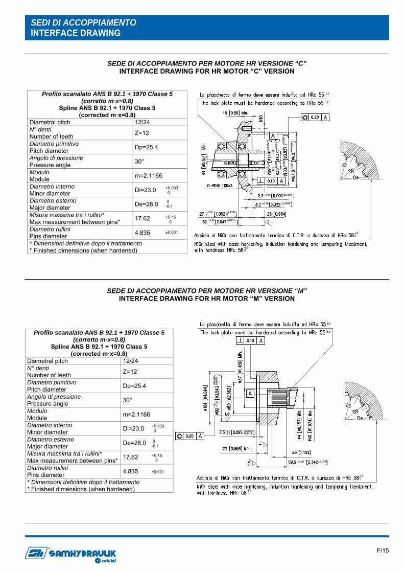
Profilo scanalato ANS B 92.1 + 1970 Classe 5 (corretto m·x=0.8)
Spline ANS B 92.1 + 1970 Class 5 (corrected m·x=0.8)
Diametral pitch 12/24 N° denti Number of teeth Z=12
Diametro primitivo Pitch diameter Dp=25.4
Angolo di pressione Pressure angle 30°
Modulo Module m=2.1166
Diametro interno Minor diameter Di=23.0
Diametro esterno Major diameter De=28.0
Misura massima tra i rullini* Max measurement between pins* 17.62
Diametro rullini Pins diameter 4.835
* Dimensioni definitive dopo il trattamento * Finished dimensions (when hardened)
+0.033 0
0 -0.1
+0.15 0
±0.001
SEDI DI ACCOPPIAMENTO INTERFACE DRAWING
SEDE DI ACCOPPIAMENTO PER MOTORE HR VERSIONE “C” INTERFACE DRAWING FOR HR MOTOR “C” VERSION
SEDE DI ACCOPPIAMENTO PER MOTORE HR VERSIONE “M” INTERFACE DRAWING FOR HR MOTOR “M” VERSION
F/16 orbital
R
orbitalorbital
R
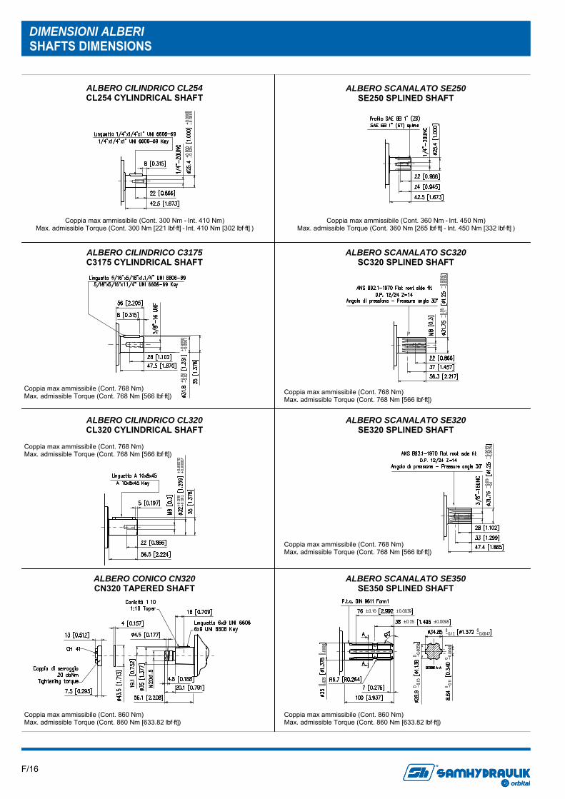
DIMENSIONI ALBERI SHAFTS DIMENSIONS
ALBERO CILINDRICO CL320 CL320 CYLINDRICAL SHAFT
ALBERO CONICO CN320 CN320 TAPERED SHAFT
ALBERO CILINDRICO C3175 C3175 CYLINDRICAL SHAFT
ALBERO SCANALATO SC320 SC320 SPLINED SHAFT
ALBERO SCANALATO SE320 SE320 SPLINED SHAFT
Coppia max ammissibile (Cont. 300 Nm - Int. 410 Nm) Max. admissible Torque (Cont. 300 Nm [221 lbf·ft] - Int. 410 Nm [302 lbf·ft] )
Coppia max ammissibile (Cont. 360 Nm - Int. 450 Nm) Max. admissible Torque (Cont. 360 Nm [265 lbf·ft] - Int. 450 Nm [332 lbf·ft] )
ALBERO SCANALATO SE250 SE250 SPLINED SHAFT
ALBERO CILINDRICO CL254 CL254 CYLINDRICAL SHAFT
ALBERO SCANALATO SE350 SE350 SPLINED SHAFT
Coppia max ammissibile (Cont. 768 Nm) Max. admissible Torque (Cont. 768 Nm [566 lbf·ft])
Coppia max ammissibile (Cont. 768 Nm) Max. admissible Torque (Cont. 768 Nm [566 lbf·ft])
Coppia max ammissibile (Cont. 768 Nm) Max. admissible Torque (Cont. 768 Nm [566 lbf·ft])
Coppia max ammissibile (Cont. 860 Nm) Max. admissible Torque (Cont. 860 Nm [633.82 lbf·ft])
Coppia max ammissibile (Cont. 860 Nm) Max. admissible Torque (Cont. 860 Nm [633.82 lbf·ft])
Coppia max ammissibile (Cont. 768 Nm) Max. admissible Torque (Cont. 768 Nm [566 lbf·ft])
F/17 orbital
R
orbitalorbital
R
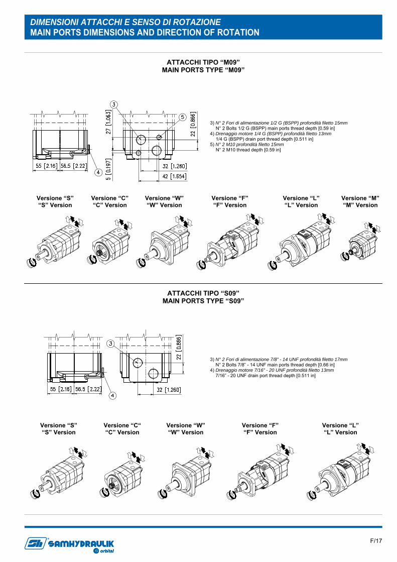
DIMENSIONI ATTACCHI E SENSO DI ROTAZIONE MAIN PORTS DIMENSIONS AND DIRECTION OF ROTATION
ATTACCHI TIPO “M09” MAIN PORTS TYPE “M09”
ATTACCHI TIPO “S09” MAIN PORTS TYPE “S09”
3) N° 2 Fori di alimentazione 1/2 G (BSPP) profondità filetto 15mm N° 2 Bolts 1/2 G (BSPP) main ports thread depth [0.59 in] 4) Drenaggio motore 1/4 G (BSPP) profondità filetto 13mm 1/4 G (BSPP) drain port thread depth [0.511 in] 5) N° 2 M10 profondità filetto 15mm N° 2 M10 thread depth [0.59 in]
Versione “S” “S” Version
Versione “C“ “C” Version
Versione “W” “W” Version
Versione “L” “L” Version
Versione “F” “F” Version
3) N° 2 Fori di alimentazione 7/8” - 14 UNF profondità filetto 17mm N° 2 Bolts 7/8” - 14 UNF main ports thread depth [0.66 in] 4) Drenaggio motore 7/16” - 20 UNF profondità filetto 13mm 7/16” - 20 UNF drain port thread depth [0.511 in]
Versione “S” “S” Version
Versione “C” “C” Version
Versione “W” “W” Version
Versione “L” “L” Version
Versione “F” “F” Version
Versione “M” “M” Version

F/18 orbital
R
orbitalorbital
R
3) N° 2 Fori di alimentazione 1” 1/16 - 12 UN profondità filetto 20mm N° 2 Bolts 1” 1/16 - 12 UN main ports thread depth [0.78 in] 4) Drenaggio motore 7/16” - 20 UNF profondità filetto 13mm 7/16” - 20 UNF drain port thread depth [0.511 in]
3) N° 2 Fori di alimentazione 7/8” - 14 UNF profondità filetto 17mm N° 2 Bolts 7/8” - 14 UNF main ports thread depth [0.66 in] 4) Drenaggio motore 7/16” - 20 UNF profondità filetto 13mm 7/16” - 20 UNF drain port thread depth [0.511 in]
3) N° 2 Fori di alimentazione 1” 1/16 - 12 UN profondità filetto 17mm N° 2 Bolts 1” 1/16 - 12 UN main ports thread depth [0.66 in] 4) Drenaggio motore 7/16” - 20 UNF profondità filetto 13mm 7/16” - 20 UNF drain port thread depth [0.511 in]
ATTACCHI LATERALI TIPO “L09” MAIN PORTS POSITIONED 180° APART TYPE “L09”
ATTACCHI FRONTALI TIPO “F09” END MAIN PORTS TYPE “F09”
ATTACCHI FRONTALI TIPO “R09” END MAIN PORTS TYPE “R09”
A RICHIESTA UPON REQUEST
Versione “S” “S” Version
Versione “C“ “C” Version
Versione “W” “W” Version
Versione “L” “L” Version
Versione “F” “F” Version
Versione “M” “M” Version
Versione “L” “L” Version
Versione “F” “F” Version
Versione “C“ “C” Version
Versione “S” “S” Version
Versione “W“ “W” Version

F/19 orbital
R
orbitalorbital
R
Per il montaggio diretto della valvola di lavaggio sui motori è necessario utilizzare un coperchio speciale. Questo è possibile solo con gli attacchi “M09 - S09”. Se si vuole predisporre il motore con valvola di lavaggio è necessario specificare in fase d’ordine il tipo di valvola 06-09-15-21 (vedere il punto 9 del codice di ordinazione)
The mount the flushing valve on motors, it is necessary to use a special cover. This is only possible with the “M09 - S09” main ports. If it is necessary to assembly the flushing valve on motors, to specify in the purchase order the valves type 06-09-15-21 (See position 9 of ordering code)
VERSIONI SPECIALI SPECIAL VERSION
ATTACCO DRENAGGIO SECONDARIO (LATO MANDATA) SECONDARY DRAIN PORT (AT DELIVERY SIDE)
COPERCHIO SPECIALE PER VALVOLA DI LAVAGGIO SPECIAL COVER FOR FLUSHING VALVE
Per i motori con versione S-W-C è possibile inserire un secondario attacco di drenaggio (lato mandata). Se si vuole predisporre il motore con un secondario attacco di drenaggio è necessario specificare in fase d’ordine il valore “OK” per versione metrica o “SK” per versione SAE (vedere punto 2A del codice di ordinazione).
For the motor with S-W-C version, it is possible to put a secondary drain port (at delivery side). If it is necessary on the motor a secondary drain port, to specify in the purchase order the value “OK” for metric version or “SK” for SAE version (See position 2A of ordering code)
1) Drenaggio motore 1/4 G (BSPP) (OK) 1/4 G (BSPP) drain port (OK) Drenaggio motore 7/16” - 20 UNF (SK) 7/16” - 20 UNF drain port (SK)
Per maggiori informazioni sulla valvola di lavaggio, consultare la sezione Valvole ed Accessori o il Bollettino Informativo 05-0082-A04 For more informations on the Flushing valve, see the Valves and Accessories section or Service Bulletin - 05-0082-A04
E’ raccomandata la versione Bassi Trafilamenti, in caso di applicazioni a basse portate e contemporaneamente alta pressione di esercizio. La versione Bassi Trafilamenti, differisce dalla versione Standard, per dei componenti interni differenti.
For applications with low flow and high working pressure, it is recommended the Low Leakage version. The Low Leakage version differs from the standard version for the different internal components.
BASSI TRAFILAMENTI LOW LEAKAGE
Versione “S” “S” Version
Versione “W” “W” Version
Versione “C” “C” Version
F/20 orbital
R
orbitalorbital
R
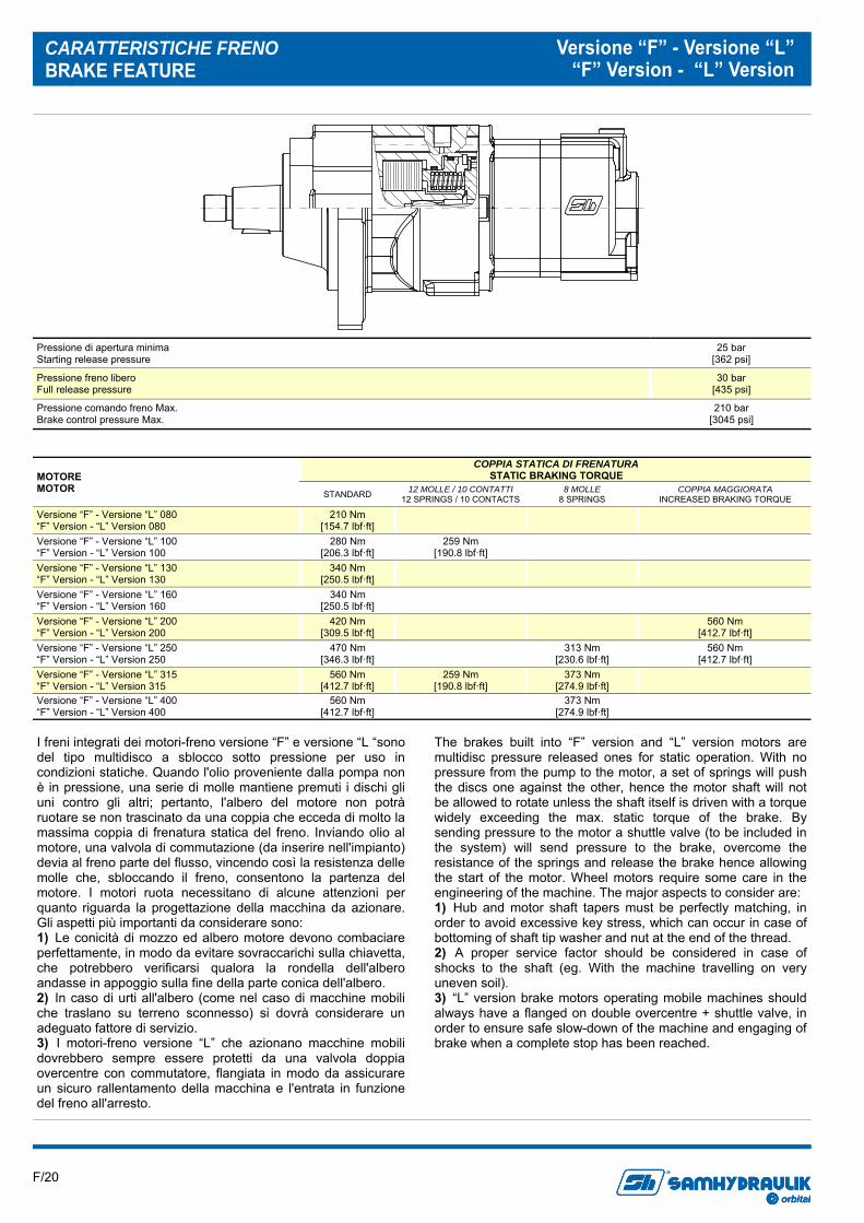
CARATTERISTICHE FRENO BRAKE FEATURE
Versione “F” - Versione “L” “F” Version - “L” Version
Pressione di apertura minima Starting release pressure
25 bar [362 psi]
Pressione freno libero Full release pressure
30 bar [435 psi]
Pressione comando freno Max. Brake control pressure Max.
210 bar [3045 psi]
MOTORE MOTOR STANDARD 12 MOLLE / 10 CONTATTI
12 SPRINGS / 10 CONTACTS 8 MOLLE
8 SPRINGS COPPIA MAGGIORATA
INCREASED BRAKING TORQUE
Versione “F” - Versione “L” 080 “F” Version - “L” Version 080
210 Nm [154.7 lbf·ft]
Versione “F” - Versione “L” 100 “F” Version - “L” Version 100
280 Nm [206.3 lbf·ft]
259 Nm [190.8 lbf·ft]
Versione “F” - Versione “L” 130 “F” Version - “L” Version 130
340 Nm [250.5 lbf·ft]
Versione “F” - Versione “L” 160 “F” Version - “L” Version 160
340 Nm [250.5 lbf·ft]
Versione “F” - Versione “L” 200 “F” Version - “L” Version 200
420 Nm [309.5 lbf·ft] 560 Nm
[412.7 lbf·ft] Versione “F” - Versione “L” 250 “F” Version - “L” Version 250
470 Nm [346.3 lbf·ft] 313 Nm
[230.6 lbf·ft] 560 Nm
[412.7 lbf·ft] Versione “F” - Versione “L” 315 “F” Version - “L” Version 315
560 Nm [412.7 lbf·ft]
259 Nm [190.8 lbf·ft]
373 Nm [274.9 lbf·ft]
Versione “F” - Versione “L” 400 “F” Version - “L” Version 400
560 Nm [412.7 lbf·ft] 373 Nm
[274.9 lbf·ft]
COPPIA STATICA DI FRENATURA STATIC BRAKING TORQUE
I freni integrati dei motori-freno versione “F” e versione “L “sono del tipo multidisco a sblocco sotto pressione per uso in condizioni statiche. Quando l'olio proveniente dalla pompa non è in pressione, una serie di molle mantiene premuti i dischi gli uni contro gli altri; pertanto, l'albero del motore non potrà ruotare se non trascinato da una coppia che ecceda di molto la massima coppia di frenatura statica del freno. Inviando olio al motore, una valvola di commutazione (da inserire nell'impianto) devia al freno parte del flusso, vincendo così la resistenza delle molle che, sbloccando il freno, consentono la partenza del motore. I motori ruota necessitano di alcune attenzioni per quanto riguarda la progettazione della macchina da azionare. Gli aspetti più importanti da considerare sono: 1) Le conicità di mozzo ed albero motore devono combaciare perfettamente, in modo da evitare sovraccarichi sulla chiavetta, che potrebbero verificarsi qualora la rondella dell'albero andasse in appoggio sulla fine della parte conica dell'albero. 2) In caso di urti all'albero (come nel caso di macchine mobili che traslano su terreno sconnesso) si dovrà considerare un adeguato fattore di servizio. 3) I motori-freno versione “L” che azionano macchine mobili dovrebbero sempre essere protetti da una valvola doppia overcentre con commutatore, flangiata in modo da assicurare un sicuro rallentamento della macchina e l'entrata in funzione del freno all'arresto.
The brakes built into “F” version and “L” version motors are multidisc pressure released ones for static operation. With no pressure from the pump to the motor, a set of springs will push the discs one against the other, hence the motor shaft will not be allowed to rotate unless the shaft itself is driven with a torque widely exceeding the max. static torque of the brake. By sending pressure to the motor a shuttle valve (to be included in the system) will send pressure to the brake, overcome the resistance of the springs and release the brake hence allowing the start of the motor. Wheel motors require some care in the engineering of the machine. The major aspects to consider are: 1) Hub and motor shaft tapers must be perfectly matching, in order to avoid excessive key stress, which can occur in case of bottoming of shaft tip washer and nut at the end of the thread. 2) A proper service factor should be considered in case of shocks to the shaft (eg. With the machine travelling on very uneven soil). 3) “L” version brake motors operating mobile machines should always have a flanged on double overcentre + shuttle valve, in order to ensure safe slow-down of the machine and engaging of brake when a complete stop has been reached.
F/21 orbital
R
orbitalorbital
R
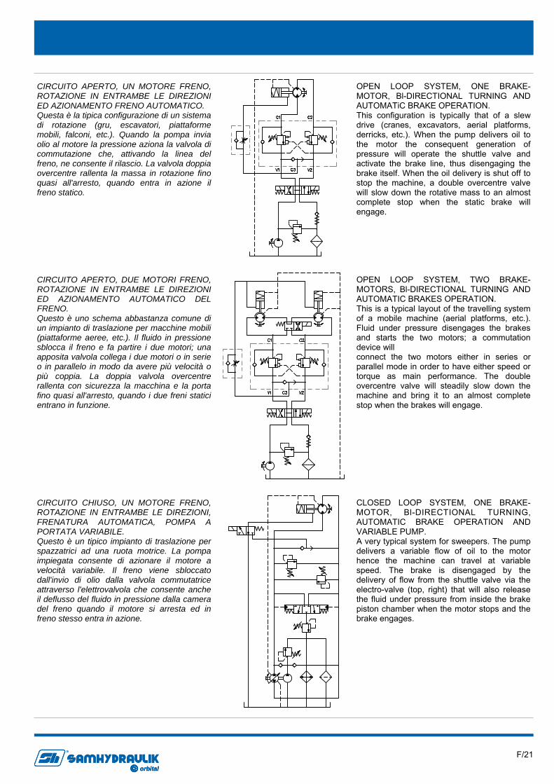
CIRCUITO CHIUSO, UN MOTORE FRENO, ROTAZIONE IN ENTRAMBE LE DIREZIONI, FRENATURA AUTOMATICA, POMPA A PORTATA VARIABILE. Questo è un tipico impianto di traslazione per spazzatrici ad una ruota motrice. La pompa impiegata consente di azionare il motore a velocità variabile. Il freno viene sbloccato dall'invio di olio dalla valvola commutatrice attraverso l'elettrovalvola che consente anche il deflusso del fluido in pressione dalla camera del freno quando il motore si arresta ed in freno stesso entra in azione.
CLOSED LOOP SYSTEM, ONE BRAKE-MOTOR, Bl-DIRECTIONAL TURNING, AUTOMATIC BRAKE OPERATION AND VARIABLE PUMP. A very typical system for sweepers. The pump delivers a variable flow of oil to the motor hence the machine can travel at variable speed. The brake is disengaged by the delivery of flow from the shuttle valve via the electro-valve (top, right) that will also release the fluid under pressure from inside the brake piston chamber when the motor stops and the brake engages.
CIRCUITO APERTO, DUE MOTORI FRENO, ROTAZIONE IN ENTRAMBE LE DIREZIONI ED AZIONAMENTO AUTOMATICO DEL FRENO. Questo è uno schema abbastanza comune di un impianto di traslazione per macchine mobili (piattaforme aeree, etc.). Il fluido in pressione sblocca il freno e fa partire i due motori; una apposita valvola collega i due motori o in serie o in parallelo in modo da avere più velocità o più coppia. La doppia valvola overcentre rallenta con sicurezza la macchina e la porta fino quasi all'arresto, quando i due freni statici entrano in funzione.
OPEN LOOP SYSTEM, TWO BRAKE-MOTORS, Bl-DIRECTIONAL TURNING AND AUTOMATIC BRAKES OPERATION. This is a typical layout of the travelling system of a mobile machine (aerial platforms, etc.). Fluid under pressure disengages the brakes and starts the two motors; a commutation device will connect the two motors either in series or parallel mode in order to have either speed or torque as main performance. The double overcentre valve will steadily slow down the machine and bring it to an almost complete stop when the brakes will engage.
CIRCUITO APERTO, UN MOTORE FRENO, ROTAZIONE IN ENTRAMBE LE DIREZIONI ED AZIONAMENTO FRENO AUTOMATICO. Questa è la tipica configurazione di un sistema di rotazione (gru, escavatori, piattaforme mobili, falconi, etc.). Quando la pompa invia olio al motore la pressione aziona la valvola di commutazione che, attivando la linea del freno, ne consente il rilascio. La valvola doppia overcentre rallenta la massa in rotazione fino quasi all'arresto, quando entra in azione il freno statico.
OPEN LOOP SYSTEM, ONE BRAKE-MOTOR, Bl-DIRECTIONAL TURNING AND AUTOMATiC BRAKE OPERATION. This configuration is typically that of a slew drive (cranes, excavators, aerial platforms, derricks, etc.). When the pump delivers oil to the motor the consequent generation of pressure will operate the shuttle valve and activate the brake line, thus disengaging the brake itself. When the oil delivery is shut off to stop the machine, a double overcentre valve will slow down the rotative mass to an almost complete stop when the static brake will engage.
F/22 orbital
R
orbitalorbital
R
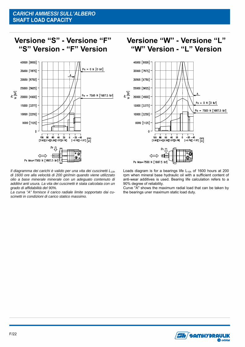
CARICHI AMMESSI SULL’ALBERO SHAFT LOAD CAPACITY
Il diagramma dei carichi è valido per una vita dei cuscinetti L10h di 1600 ore alla velocità di 200 giri/min quando viene utilizzato olio a base minerale minerale con un adeguato contenuto di additivi anti usura. La vita dei cuscinetti è stata calcolata con un grado di affidabilità del 90%. La curva "A" fornisce il carico radiale limite sopportato dai cu-scinetti in condizioni di carico statico massimo.
Loads diagram is for a bearings life L10h of 1600 hours at 200 rpm when mineral base hydraulic oil with a sufficient content of anti-wear additives is used. Bearing life calculation refers to a 90% degree of reliability. Curve "A" shows the maximum radial load that can be taken by the bearings uner maximum static load duty.
Versione “S” - Versione “F” “S” Version - “F” Version
Versione “W” - Versione “L” “W” Version - “L” Version
F/23 orbital
R
orbitalorbital
R
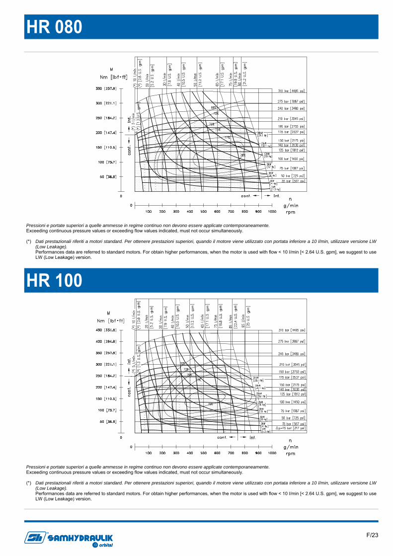
HR 080
HR 100
Pressioni e portate superiori a quelle ammesse in regime continuo non devono essere applicate contemporaneamente. Exceeding continuous pressure values or exceeding flow values indicated, must not occur simultaneously. (*) Dati prestazionali riferiti a motori standard. Per ottenere prestazioni superiori, quando il motore viene utilizzato con portata inferiore a 10 l/min, utilizzare versione LW
(Low Leakage). Performances data are referred to standard motors. For obtain higher performances, when the motor is used with flow < 10 l/min [< 2.64 U.S. gpm], we suggest to use
LW (Low Leakage) version.
F/24 orbital
R
orbitalorbital
R
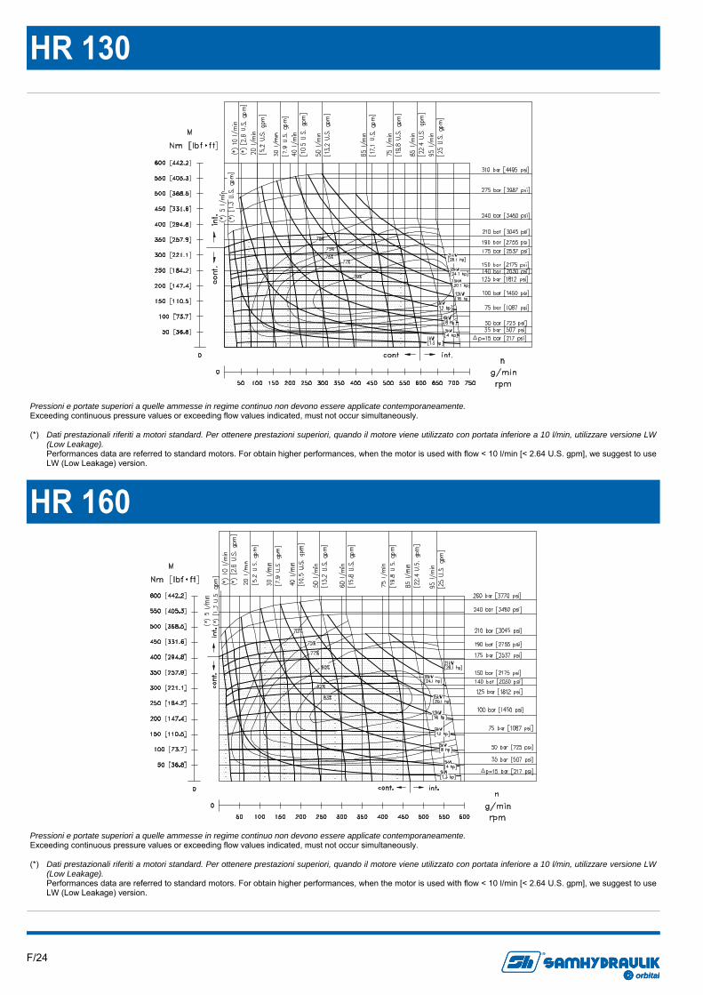
HR 130
HR 160
Pressioni e portate superiori a quelle ammesse in regime continuo non devono essere applicate contemporaneamente. Exceeding continuous pressure values or exceeding flow values indicated, must not occur simultaneously. (*) Dati prestazionali riferiti a motori standard. Per ottenere prestazioni superiori, quando il motore viene utilizzato con portata inferiore a 10 l/min, utilizzare versione LW
(Low Leakage). Performances data are referred to standard motors. For obtain higher performances, when the motor is used with flow < 10 l/min [< 2.64 U.S. gpm], we suggest to use
LW (Low Leakage) version.
F/25 orbital
R
orbitalorbital
R
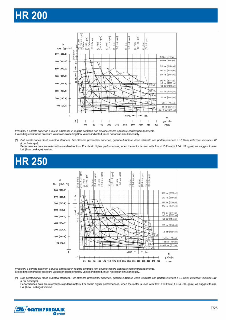
HR 200
HR 250
Pressioni e portate superiori a quelle ammesse in regime continuo non devono essere applicate contemporaneamente. Exceeding continuous pressure values or exceeding flow values indicated, must not occur simultaneously. (*) Dati prestazionali riferiti a motori standard. Per ottenere prestazioni superiori, quando il motore viene utilizzato con portata inferiore a 10 l/min, utilizzare versione LW
(Low Leakage). Performances data are referred to standard motors. For obtain higher performances, when the motor is used with flow < 10 l/min [< 2.64 U.S. gpm], we suggest to use
LW (Low Leakage) version.

F/26 orbital
R
orbitalorbital
R
HR 315
HR 400
Pressioni e portate superiori a quelle ammesse in regime continuo non devono essere applicate contemporaneamente. Exceeding continuous pressure values or exceeding flow values indicated, must not occur simultaneously. (*) Dati prestazionali riferiti a motori standard. Per ottenere prestazioni superiori, quando il motore viene utilizzato con portata inferiore a 10 l/min, utilizzare versione LW
(Low Leakage). Performances data are referred to standard motors. For obtain higher performances, when the motor is used with flow < 10 l/min [< 2.64 U.S. gpm], we suggest to use
LW (Low Leakage) version.
F/27 orbital
R
orbitalorbital
R
Informazioni sul prodotto Dati i continui sviluppi, le modifiche e le migliorie al prodotto, la S.AM Hydraulik Spa non sarà responsabile per eventuali informazioni che possano indurre in errore, od erronee, riportate da cataloghi, istruzioni, disegni, dati tecnici e altri dati forniti dalla S.A.M. Hydraulik Spa. Non sarà possibile basare alcun procedimento legale su tale materiale. Modifiche del prodotto. La S.A.M. Hydraulik Spa si riserva il diritto di variare i suoi prodotti, anche quelli già ordinati, senza notifica. Notice Due to the continuous product developments, modifications and improvements S.A.M. Hydraulik Spa will not be held responsible for any erroneous information or data that may lead to errors, indicated in catalogues, instructions, dra-wings, technical data and other data supplied by S.A.M. Hydraulik Spa. Therefore, legal actions cannot be based on such material. Product development. S.A.M. Hydraulik Spa reserves the right to make changes to its products, even for those already ordered, without notice.