HINTERRADFAHRRADTRÄGER ZUR MONTAGE AUF DER ... · 13) Coloque primero en el portabicicletas la...
28
PARMA GB D F I E Fitting instructions Montageanleitung Instructions de montage Istruzioni per il montaggio Instrucciones de montaje PL CZ Instrukcja montażu Návod na montáž * Kg MAX loaded MAX 60 Kg = + Car manual Art. 706/3A = 15,77 Kg * Art. 706/3 = 17,38 Kg * Art. 706/4 = 20,03 Kg * x4 x3 Art. 706 = 15,58 Kg * x2 Art. 706 Art. 706/3 - 706/3A Art. 706/4 Art. 706/4 706_PARMA_31/01/15 1/28 Copyright © 2012 Peruzzo Italy - MADE IN ITALY SLO Navodila za montažo Instruções para a montagem NL Instructies voor montage PT THE REAR CYCLE RACK FOR MOUNTING ON TOW BAR HINTERRADFAHRRADTRÄGER ZUR MONTAGE AUF DER ANHÄNGERKUPPLUNG PORTE VELOS ARRIERE POUR DISPOSITIF D’ATTELAGE PORTACICLO POSTERIORE GANCIO DI TRAINO PORTA BICICLETA PARA APLICAR A LA BOLA DE REMOLQUE BAGAŻNIK ROWEROWY NA HAK HOLOWNICZY ZADNÍ NOSIČ JÍZDNÍCH KOL PRO MONTÁŽ NA TAŽNÉ ZAŘÍZENÍ NOSILEC KOLES NA VLEČNI KLJUKI PORTACICLO TRASEIRO PARA O GANCHO DE TRAÇÃO FIETSENHOUDER VOOR ACHTERAAN OP TREKHAAK
Transcript of HINTERRADFAHRRADTRÄGER ZUR MONTAGE AUF DER ... · 13) Coloque primero en el portabicicletas la...
PARMA
GB
D
F
I
E
Fitting instructionsMontageanleitungInstructions de montageIstruzioni per il montaggioInstrucciones de montaje
PL
CZ
Instrukcja montażuNávod na montáž
*KgMAX
loaded
MAX 60 Kg
= +
Car manual
Art. 706/3A = 15,77 Kg *Art. 706/3 = 17,38 Kg *
Art. 706/4 = 20,03 Kg *
x4
x3
Art. 706 = 15,58 Kg *
x2
Art. 706Art. 706/3 - 706/3AArt. 706/4
Art. 706/4
706_PARMA_31/01/15 1/28 Copyright © 2012 Peruzzo Italy - MADE IN ITALY
SLO Navodila za montažoInstruções para a montagem
NL Instructies voor montagePT
THE REAR CYCLE RACK FOR MOUNTING ON TOW BARHINTERRADFAHRRADTRÄGER ZUR MONTAGE AUF DER ANHÄNGERKUPPLUNGPORTE VELOS ARRIERE POUR DISPOSITIF D’ATTELAGEPORTACICLO POSTERIORE GANCIO DI TRAINOPORTA BICICLETA PARA APLICAR A LA BOLA DE REMOLQUEBAGAŻNIK ROWEROWY NA HAK HOLOWNICZYZADNÍ NOSIČ JÍZDNÍCH KOL PRO MONTÁŽ NA TAŽNÉ ZAŘÍZENÍNOSILEC KOLES NA VLEČNI KLJUKIPORTACICLO TRASEIRO PARA O GANCHO DE TRAÇÃOFIETSENHOUDER VOOR ACHTERAAN OP TREKHAAK
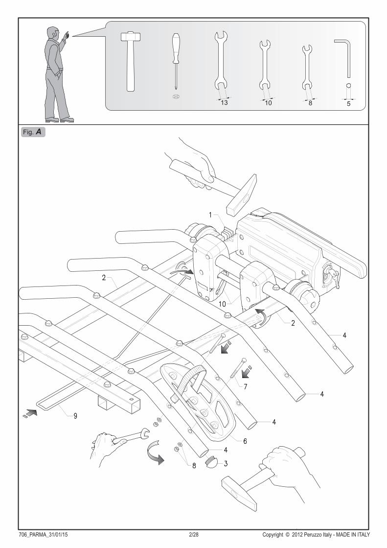
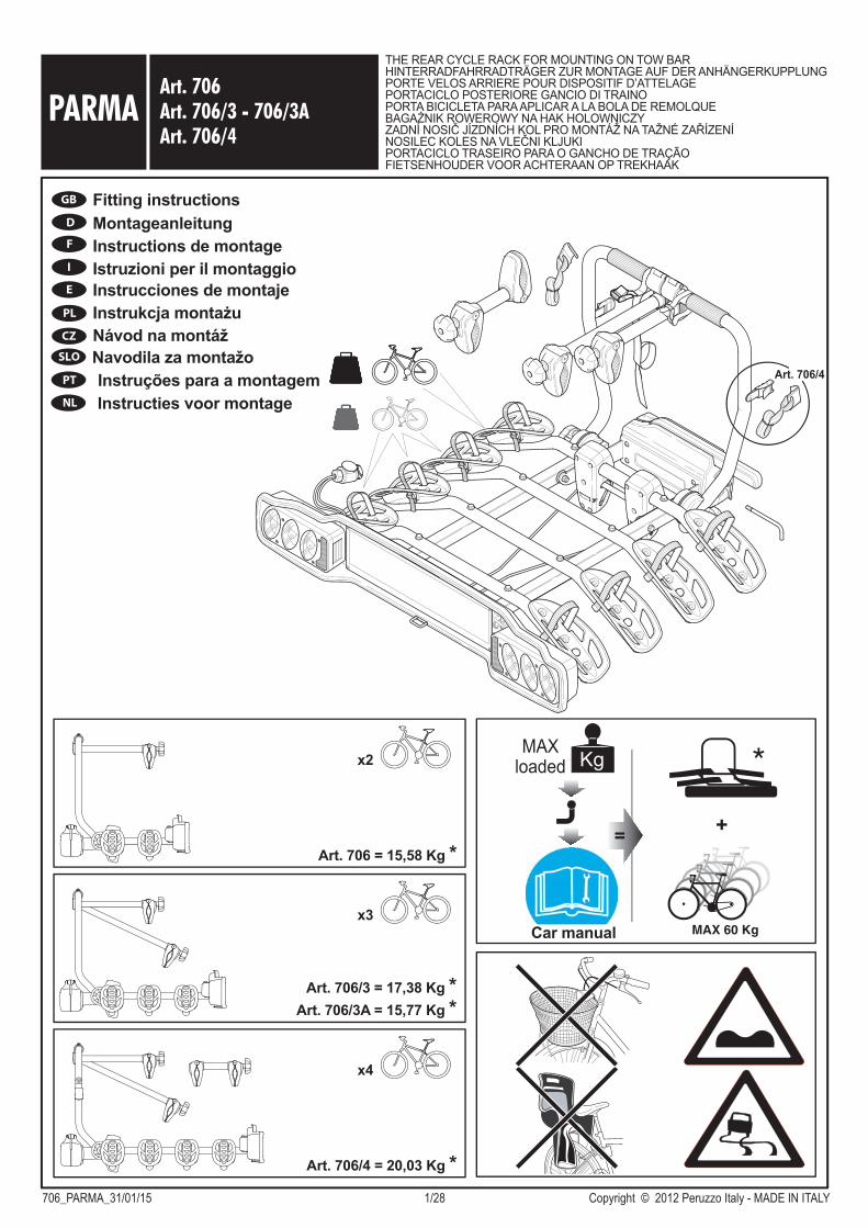
Fig. A
706_PARMA_31/01/15 2/28 Copyright © 2012 Peruzzo Italy - MADE IN ITALY
13 10 8 5

Fig. B
Fig. C
706_PARMA_31/01/15 3/28 Copyright © 2012 Peruzzo Italy - MADE IN ITALY
5
Fig. D1
x2
Fig. D2
706_PARMA_31/01/15 4/28 Copyright © 2012 Peruzzo Italy - MADE IN ITALY
Art. 706/4
1
1
3
3
2
2
5
Fig. E1
Fig. E2CLAC
K
706_PARMA_31/01/15 5/28 Copyright © 2012 Peruzzo Italy - MADE IN ITALY

Fig. G
Fig. H1
Fig. H2
1
2
Fig. F
706_PARMA_31/01/15 6/28 Copyright © 2012 Peruzzo Italy - MADE IN ITALY
Art. 706/4
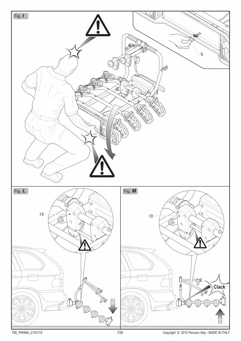
Fig. I
Fig. L Fig. M
706_PARMA_31/01/15 7/28 Copyright © 2012 Peruzzo Italy - MADE IN ITALY
Clack

706_PARMA_31/01/15 8/28 Copyright © 2012 Peruzzo Italy - MADE IN ITALY
GBASSEMBLY AND USER INSTRUCTIONSWhenever this product is used the following information must be taken into consideration: the bike rack is a safe product if used correctly, but if it is used incorrectly it can cause damages to you and to anyone driving behind you.
1) Insert the plugs 1 in the square bearing tubes 2 (Fig. A).2) Insert the plugs 3 in the bike carrier bars 4 (Fig. A ) and in the bike
fixing arch 5 (Fig. D2).3) Mount the tyre cradles 6 on the bike carrier bar 4 in the most suitable
positions for the dimensions of your bike and fix them with the screws 7, nuts and washers 8 (Fig. A).
4) Fix the hook 9 to the tilt mechanisms 10 (Fig. A).5) Mount the rear lights 11 to the lighting board 12 and fix together with
the washers and nuts 13 (Fig. B); take care not to damage the wires and not to over-tighten the nuts as this could damage the plastic parts. Thread the 13 pin plug through the central hole of the lighting board 12.
6) Fix the number plate frame 14 to the lighting board 12 with the screws 15 (Fig. B).
7) Fix the lighting board assembly 12 to the square tube 16 with the screws 17, the nuts and the washers 18; make sure you thread the tilt hook 9 into the slot provided (Fig. C).
8) Mounting the bike fixing arch 5:- Undo and remove the knobs 19 and the washers 20 from both sides (Fig. D1);- Carry out the operations 1, 2 (only for art. 706/4) and 3 (Fig. D2);- Insert the bike fixing arch 5 in the half pipe of the adjustment elements 21, then fix it with the washers 20 and the knobs 19 (Fig. D2).
For personal safety and to avoid damaging the vehicle we recommend 2 people mount the bike carrier.
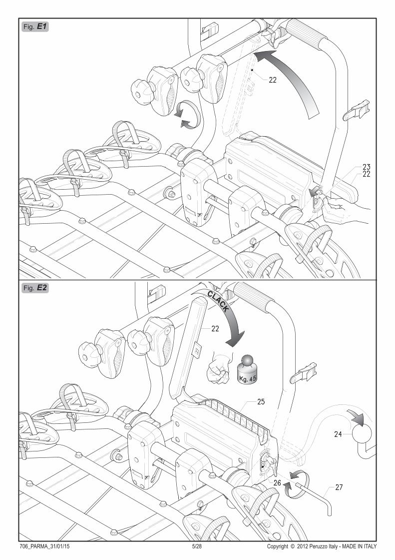
9) Push the lever 22 upwards, to disengage it turn the wrench 23 counter clockwise (Fig. E1).
10) Place the fixing block 24 on the towball 25 (Fig. E2).11) Close the clamping device by lowering the lever 22 : at least 45 kg.
clamping force is required. (Fig. E2).
Adjustment of closing hand forceIt is always necessary to make the first adjustment when the product is purchased. Then, every time the product is used, the clamping force must be checked and adjusted if necessary. In order to prevent accidents and damage it is advisable to ask a second person to assist you in this procedure as well. After disengaging and lifting the lever 22 the second person must hold the cycle carrier in a horizontal position. The screw 26 must be adjusted with the wrench provided 27 so that the clamping force on the lever is increased to a minimum of 45 Kg. (Fig. E2). Make sure that the bike rack does not rotate when the clamping device has been locked.
ONLY FOR ART.706/412) Attach the strap hooks 35 to the edges of the vehicle hatch, then insert
the straps in the buckles 34 (make sure the inlet direction is correct) (Fig. F).IMPORTANT: Give the straps a good tug to check for tightness. Check the tightness before starting and during the trip.
HOW TO INSTALL THE BIKE CARRIER ON THE TOWBALL
13) Place the biggest and heaviest bike on the bike rack first, position the wheels in the tire cradles 6 and lean it up against the bike fixing arch 5. Secure the bike to the bike fixing arch 5 with the fixing strap 28 (Fig. H1). Secure the wheels by means of the fixing straps 29 (Fig. G).
POSITIONING AND FIXING THE BIKES ON THE BIKE RACK
BIKE RACK INCLINATION (Fig. I/L/M)To tilt the bike rack hold it up with one hand while you pull the hook 9 with the other (Fig. I). To avoid injury or damage, this operation of tilting the bike rack should be carried out with the help of a third person. To close the bike rack, lift it until the tilt mechanism 10 engages completely by passing from the tilt position (Fig. L) to the closed position (Fig. M).
14) Repeat the operations in 13 for the second, third and fourth bikes. The second and third bikes are secured to the fixing arch 5 with the fixing arms 30/31 (Fig. H1), whereas the fourth bike is secured to the third bike with fixing arm 32 (Fig. H2).IMPORTANT: For safe transportation of the load the bike carrier is supplied with a strap 33 for tying all the bikes to the fixing arch 5. Check that the belt is mounted correctly by pulling on it.
As well as the information described below please observe the "Conditions, suggestions and limits for use" specified in the EC type test certificate.
- Weight and maximum capacity of "PARMA" bike racks:* Model 706/4 (20,03 kg.) ---> 4 bikes, max. capacity 60 kg.* Model 706/3 (17,38 kg.) ---> 3 bikes, max. capacity 60 kg.* Model 706/3A (15,77 kg.) ---> 3 bikes, max. capacity 60 kg.* Model 706 (15,58 kg.) ---> 2 bikes, max. capacity 60 kg.
- Never exceed the permitted capacity of the towing hook installed. The combined weight of the bike rack and the load must never exceed the permitted capacity. Keep the towing hook ball surface clean from dirt and oil.
- The driver is always responsible for the load he is transporting and consequently he is also responsible for checking the fastenings both before starting the trip and at regular intervals during the trip.
- Check the car manual for the specifications concerning the maximum permissible rear axle weight.
- Verify compliance with the value D (maximum load bearing capacity) of the towball specified by the car or towball manufacturer; the value D for the towball must be at least (760 Kg) 7.6kN; older towballs often only specify the permissible load on the towball GA and the total permissible load of the towing vehicle GK rather than value D; in this case the value D can be calculated using the values specified in the vehicle maintenance or registration booklet:
- Remove from the transported bikes children's seats, transport
baskets, rain covers or other elements that could get lost or increase the air resistance.
- Do not carry more bikes than the number indicated for a specific model.
- Bike parts, such as for example the handlebars or pedals, must not be left in the normal position of use; they must be folded to avoid dangerous projections.
- Ensure that the bike rack is fitted correctly on the towing hook and that the bikes are secured as instructed.
- The bike rack is only suitable for transporting bicycles.
ATTENTION – SAFETY REQUIREMENTS
D = x9,81 (GA x GK)
1000 (GA + GK)(D in [kN] / GA in [kg] / GK in [kg])

706_PARMA_31/01/15 9/28 Copyright © 2012 Peruzzo Italy - MADE IN ITALY
GB- Before leaving, check that the rear lights function correctly. Also check
that the indicator lights work correctly.- Keep the connections clean (lighting board power plug and power
outlet on the vehicle ); use suitable cleaning materials when necessary.- Do not use and/or attach the bike rack to the car before making the
electrical connections.- Check that the electrical cables are not damaged or likely to be
damaged by interference with other elements of the vehicle or that they could, in any way, be accidently cut.
- The lighting devices are not designed t be immersed in water.- Any major work required to be done on the elec trical system and
connections must be performed by qualified personnel.- Provide an additional number plate to be attached to the towball bike
rack.- Keep in mind that when driving a vehicle with a towball bike carrier the
rear load projection is different to the normal projection, therefore, take care when reversing or parking as you need to consider the longer length of the vehicle; also be aware that the weight of the bikes loaded on the carrier alter the handling characteristics of the vehicle particularly in crosswind conditions, on bends or when braking; When on the road, respect the highway code speed limits and pay attention to the road conditions to prevent jolts.
- If the driver’s rear view is obstructed the vehicle must be equipped with rearview mirrors to ensure safe driving.
- To avoid damage, if the boot lid is equipped with an automatic opening function, use this function with care.
- The rear lights of the vehicle are partially or completely covered when using the towball carrier which is why the model that you have purchased is equipped with an extra light and numberplate system. The necessary number and type of lights depend on the date of the vehicle’s first registration, as set out below:
- If the load protrudes more than 40 cm beyond the surface of the lights of the towball bike carrier then a visual sign must be attached to it.
- Check all the bike rack fixing elements after a shor t while, then at regular intervals.
- Check the distance between the bike rack, the bikes and the exhaust pipe(s) to avoid heat damages.
- To increase road safety and to reduce fuel consumption, remove the bike rack when not in use.
- Modifications to the bike rack and its components are not permitted. Immediately replace any worn or damaged part using original spare parts exclusively.
- The bike rack can be cleaned by using warm water and/or car shampoo. Store the bike rack in dry conditions at moderate temperatures.
The manufacturer is not responsible for damage caused by improper use of this product, nor for any objection made by the competent authorities with regard to the highway code.
The manufacturer shall only be responsible for manufacturing defects in the bike rack and accessory components.
THE TYPE APPROVAL CERTIFIATE CAN BE DOWNLOADED FROM THE PRODUCT TECHNICAL DATA SHEET ON OUR WEB SITE
www.peruzzosrl.com
It is not obligatory to use fog lights or reversing lights on the
towball bike carrier.
Use of a 7 pin plug is permitted.
REGISTRATION BEFORE 01.01.1987
It is not obligatory to use fog lights but it is mandatory to use
the reversing lights of the towball bike carrier.
Use of a 7 pin plug is permitted. In the event of incompatibility between socket and plug use
suitable adaptors that are readily available on the market.
REGISTRATION BETWEEN 01.01.1987 AND 31.12.1990
All the lights of the towball bike carrier must be operational. Fog
lights and reversing lights are obligatory.
It is necessary to use a relay or electric plug with a cutoff system
that ensures that the vehicle's fog lights switch off
automatically when the towball bike carrier is used and come on as soon as the plug is removed
(Only a 13 pin plug complies with this requirement).
REGISTRATION AFTER 01.01.1991
REGISTRATION AFTER 01.01.1998
The towball bike carrier must not cover the third brake lights. The third brake light must be visible
otherwise it must be repeated on the towball bike carrier.
706_PARMA_31/01/15 10/28 Copyright © 2012 Peruzzo Italy - MADE IN ITALY
DMONTAGE- UND GEBRAUCHSANLEITUNGBei jedem Gebrauch dieses Produktes müssen die nachste- henden Informationen beachtet werden: Der Fahrradträger ist ein sicheres Produkt, solange er korrekt benutzt wird. Wird er im Gegensatz dazu nicht korrekt benutzt, kann er Ihnen und anderen, hinter Ihnen fahrenden Straßenteilnehmern Schäden zufügen.
1) Die Stopfen 1 in die quadratisch geschnittenen Tragrohre 2 einfügen (Abb. A).2) Die Stopfen 3 in die Tragbügel 4 (Abb. A) und den Befestigungsbügel 5
einfügen (Abb. D2).3) Die Radaufnahmevorrichtungen 6 an die Stellen des Tragbügels 4
montieren, die für die Abmessungen Ihres Fahrrades am besten geeignet sind. Befestigen Sie die Vorrichtungen mit den Schrauben 7, den Muttern und den Unterlegscheiben 8 (Abb. A).
4) Den Haken 9 an den Schrägstellvorrichtungen 10 befestigen (Abb. A).5) Die Rücklichter 11 auf die Scheinwerferstange 12 montieren und mit
den Unterlegscheiben und Muttern 13 befestigen (Abb. B). Achten Sie darauf, dass die Kabel nicht beschädigt und die Muttern nicht zu stark angezogen werden, weil dadurch die Plastikteile Schaden nehmen könnten. Achten Sie darauf, den 13-poligen Stecker in das mittlere Loch der Scheinwerferstange 12 einzufügen.
6) Den Kennzeichenhalter 14 an der Scheinwerferstange 12 anbringen und mit den Schrauben 15 fixieren (Abb. B).
7) Die Baugruppe der Scheinwerferstange 12 an das Vierkantrohr 16 montieren und mit den Schrauben 17, den Muttern und Unterlegschei- ben 18 fixieren. Achten Sie darauf, dass der Schrägstellhaken 9 in die vorhandene Öffnung eintritt (Abb. C).
8) Anbringung des Befestigungsbügels 5:- Die Kugelgriffe 19 und Unterlegscheiben 20 beidseitig abschrauben und entfernen (Abb. D1);- Die Schritte 1, 2 (nur für art. 706/4) und 3 ausführen (Abb. D2);- Den Befestigungsbügel 5 in den Sitz der Einstellräder 21 einsetzen und ihn dann mit den Unterlegscheiben 20 und den Kugelgriffen 19 fixieren (Abb. D2).
Zur sicheren Montage des Fahrradträgers und zur Vermeidung von Beschädigungen sollte eine andere Person um Hilfe gebeten werden.
9) Den Hebel 22 nach oben umlegen. Um ihn zu entsperren, den Schlüssel 23 entgegen dem Uhrzeigersinn drehen (Abb. E1).
10) Den Befestigungsblock 24 auf der Kugel der Anhängerkupplung 25 aufsetzen (Abb. E2).
11) Die Befestigungsvorrichtung wird durch Absenken des Hebels 22 geschlossen. Die Schließkraft muss mindestens 45 kg. betragen (Abb. E2).
Einstellung der HandschließkraftBeim Kauf des Produktes muss in jedem Fall die erstmalige Einstellung vorgenommen werden. Anschließend ist die Schließkraft bei jeder erneuten Nutzung zu kontrollieren und bei Bedarf nachzustellen. Um Unfälle und Beschädigungen zu verhindern, sollte auch bei diesem Vorgang eine weitere Person um Hilfe gebeten werden. Nach dem Entsperren und Hochstellen von Hebel 22 muss der Fahrradträger von der zweiten Person in waagerechter Lage gehalten werden. Die Schraube 26 muss mit dem beiliegenden Schlüssel 27 so eingestellt werden, dass sich die Schließkraft auf dem Hebel auf mindestens 45 kg. erhöht (Abb. E2). Vergewissern Sie sich, dass der Fahrradträger sich bei geschlossener Befestigungsvorrichtung nicht dreht.
NUR FÜR ART.706/412) Die Haken in die Riemen 35 an den Rändern der Autoheckklappe
einfügen, dann die Riemen in die Schnallen 34 einführen, wobei auf die korrekte Eintrittsrichtung zu achten ist (Abb. F).WICHTIG: Prüfen Sie durch heftiges Ziehen, ob die Riemen halten. Kontrollieren Sie bei Antritt der Fahrt und während der Fahrtpausen die Riemenspannung.
MONTAGE DES FAHRRADTRÄGERS AUF DIE ANHÄNGERKUPPLUNG
POSITIONIERUNG UND BEFESTIGUNG DER FAHRRÄDER AUF DEM FAHRRADTRÄGER
SCHRÄGSTELLEN DES FAHRRADTRÄGERS (Abb. I/L/M)Um den Fahrradträger zu neigen, wird er mit einer Hand angehoben, während die andere Hand am Haken 9 (Abb. I). zieht. Um Verletzun- gen und Schäden auszuschließen, muss sich die ausführende Person beim Schrägstellen des Fahrradträgers der Hilfe einer dritten Person bedienen. Zum Schließen wird der Fahrradträger soweit hochgehoben, bis die Schrägstellvorrichtung 10 vollständig einrastet und von der Neigestellung (Abb. L) in die Schließstellung (Abb. M) übergeht.
13) Als erstes das größte und schwerste Fahrrad auf dem Träger positionie- ren, die Räder in den Radaufnahmen 6 unterbringen und das Fahrrad a n d e n B e f e s t i g u n g s b ü g e l 5 a n l e g e n . D i e Fa h r rä d e r m i t d e m Befestigungsriemen 28 am Befestigungsbügel 5 fixieren (Abb. H1). Die Räder mit den Befestigungsriemen 29 fixieren (Abb. G).
14) Wiederholen Sie die Vorgänge 13 für das zweite, dritte und vierte Fahrrad. Das zweite und dritte Fahrrad sind mit den Befestigungsarmen 30/31 am Befestigungsbügel 5 fixiert (Abb. H1), während das vierte Fahrrad mit dem Befestigungsarm 32 (Abb. H2) am dritten Fahrrad fixiert ist.WICHTIG: Für den sicheren Transport der Last ist der Fahrradträger mit dem Riemen 33 ausgestattet, mit dem alle Fahrräder am Befe- stigungsbügel 5 angebunden werden müssen. Vergewissern Sie sich durch ausreichendes Spannen des Riemens, dass dieser korrekt montiert ist.
Neben den nachstehenden Ausführungen beachten Sie bitte die "Bedingungen, Empfehlungen und Gebrauchsbeschränkungen" aus der Prüfbescheinigung für die EG-Typgenehmigung.- Gewicht und maximale Tragkraft der "PARMA":* Modell 706/4 (20,03 kg.) ---> 4 Fahrräder, max. Tragkraft 60 kg.* Modell 706/3 (17,38 kg.) ---> 3 Fahrräder, max. Tragkraft 60 kg.* Modell 706/3A (15,77 kg.) ---> 3 Fahrräder, max. Tragkraft 60 kg.* Modell 706 (15,58 kg.) ---> 2 Fahrräder, max. Tragkraft 60 kg.
- Die zulässige Höchstbelastung der installierten Anhängerkupplung darf auf keinen Fall überschritten werden. Das Gesamtgewicht des Fahrradträgers und der Last darf die zulässige Höchstbelastung in keinem Fall überschreiten. Halte Sie die Kugelfläche der Anhänger- kupplung sauber; Schmutz- und Ölspuren sind zu entfernen.
- Der Fahrer ist immer für die transportierte Last und somit auch für die Kontrolle verantwortlich, mit der sowohl beim Fahrtantritt, als auch in regelmäßigen Abständen während der Fahrt die Befestigung zu prüfen ist.
- Schlagen Sie im Betriebshandbuch des Autos nach, um zu prüfen, ob die Vorgaben für das zulässige Höchstgewicht auf der Hinterachse eingehalten sind.
- Prüfen Sie, ob der vom Hersteller des Autos oder der Anhängerkup- plung angegebene Wert D (Höchstbelastung) eingehalten ist; Der für die Anhängerkupplung angegebene Wert D muss mindestens 760 kg (7,6 kN) betragen; Ältere Anhängerkupplungen weisen häufig statt des Wertes D nur die auf der Anhängerkupplung zulässige Last GA und die zulässige Gesamtlast des ziehenden Fahrzeugs GK aus; in diesem Fall kann man den Wert D selbst errechnen, indem man die Werte aus dem Serviceheft des Fahrzeugs oder aus dem KFZ-Schein zugrundelegt:
- Entfernen Sie von den transportierten Fahrrädern Kindersitze, Körbe,
Regenüberzüge oder andere Elemente, die sich lösen oder den Luftwiderstand erhöhen können.
ACHTUNG – SICHERHEITSVORSCHRIFTEN
D = x9,81 (GA x GK)
1000 (GA + GK)(D in [kN] / GA in [kg] / GK in [kg])
706_PARMA_31/01/15 11/28 Copyright © 2012 Peruzzo Italy - MADE IN ITALY
D- Die Anzahl der transportierten Fahrräder darf die für das erworbene
Modell angegebene Höchstzahl nicht überschreiten.- Teile aufgeladener Fahrräder wie etwa Lenker oder Pedalen dürfen nicht
in Fahrstellung verbleiben, sondern sind umzulegen, damit sie nicht gefährlich weit hervorstehen.
- Überzeugen Sie sich, dass der Fahrradträger richtig auf der Anhänger- kupplung montiert ist und dass die Fahrräder gemäß der Anleitung befestigt sind.
- Der Fahrradträger eignet sich ausschließlich für den Transport von Fahrrädern.
- Bevor Sie losfahren, prüfen Sie bitte, ob die Heckleuchten einwandfrei funktionieren. Prüfen Sie insbesondere die Blinkleuchten.
- Halten Sie die Anschlüsse sauber (Stecker und Zapfwelle). Verwenden Sie dazu bei Bedarf sachgerechte Materialien.
- Den Fahrradträger nicht benutzen oder an das Auto anhängen, ohne zuvor den Stromanschluss hergestellt zu haben.
- Prüfen Sie, ob die Stromkabel beschädigt sind, von anderen Fahrzeu- gteilen beschädigt werden oder auf andere Weise ungewollt zertrennt werden können.
- Die Beleuchtungsvorrichtungen sind nicht für das Eintauchen in Wasser ausgelegt.
- Größere Eingriffe an der elektrischen Anlage und den Anschlüssen müs- sen von Fachleuten vorgenommen werden.
- Eine geeignete Kopie des Kennzeichens muss auf dem Fahrradträger für die Anhängerkupplung angebracht werden.
- Berücksichtigen Sie bitte, dass mit dem Fahrradträger auf der Anhänger- kupplung die Ausladung des Fahrzeugs hinten anders ist, als normal. Berücksichtigen Sie deshalb beim Rückwärtsfahren oder Einparken die größere Fahrzeuglänge. Berücksichtigen Sie außerdem, dass das Gewicht der auf den Fahrradträger geladenen Fahrräder die Fahreigen- schaften des Autos vor allem bei Seitenwind, in der Kurve oder beim Bremsen verändert; Halten Sie während der Fahrt die von der Straßen- verkehrsordnung vorgeschriebene Geschwindigkeit ein. Achten Sie auf den Straßenzustand und vermeiden Sie Stöße durch Schlaglöcher.
- Wenn die Sicht nach hinten verstellt ist, rüsten Sie das Fahrzeug mit geeigneten Seitenrückspiegeln aus, die eine sichere Fahrt garantieren.
- Wenn sich die Motorhaube / Heckklappe automatisch öffnen lässt, müssen Sie diese Funktion zur Schadensvorbeugung mit großer Vorsicht nutzen.
- Die Heckleuchten des Autos werden bei Nutzung der Vorrichtung für die Anhängerkupplung vollständig oder teilweise abgedunkelt. Aus diesem Grund ist der Fahrradträger, den sie er worben haben, mit einem weiteren Beleuchtungssystem und Kennzeichen ausgestattet. Die Anzahl und Art der Leuchten hängen davon ab, wann das Fahrzeug erstmalig zugelassen worden ist:
- Wenn die Last weiter als 40 cm über die Leuchten des auf der Anhängerkupplung angebrachten Fahrradträgers hervorsteht, muss sie gekennzeichnet werden.
- Kontrollieren Sie anfänglich nach einer kurzen Fahrtstrecke, anschlie- ßend in regelmäßigen Zeitabständen alle Befestigungselemente des Fahrradträgers.
- Prüfen Sie den Abstand zwischen dem Fahrradträger, den Fahrrädern und dem Auspuffrohr/e, um wärmebedingte Schäden auszuschließen.
- Um die Straßensicherheit zu erhöhen und Energie zu sparen, bauen Sie den Fahrradträger bitte ab, wenn er nicht benutzt wird.
- Es ist untersagt, am Fahrradträger und seinen Komponenten Änderun- gen vorzunehmen. Jedes verschlissene oder beschädigte Teil ist sofort und ausschließlich durch Originalersatzteile zu ersetzen.
- Der Fahrradträger lässt sich mit lauwarmem Wasser, bei Bedarf auch mit e inem speziel len Autowaschmittel reinigen. B ewahren Sie den Fahrradträger bei gemäßigten Temperaturen vor Feuchtigkeit geschützt auf.
Der Hersteller haftet nicht für Schäden, die auf den fehlerhaften Gebrauch dieses Produktes zurückgehen. Ebenso wenig haftet er für Strafen, die bei Verstößen gegen die Straßenverkehrsordnung von den zuständigen Behörden verhängt werden.
Der Hersteller haftet einzig für Herstellungsfehler am Fahrra- dträger und seinen Zusatzkomponenten.
DAS DOKUMENT ÜBER DIE TECHNISCHE ZULASSUNG KANN VON UNSERER WEBSITE
www.peruzzosrl.com
INNERHALB DES TECHNISCHEN PRODUKTDATENBLATTES HERUNTERGELADEN WERDEN.
Nebelschlussleuchten und Rückfahrleuchten für den
Fahrradträger auf der Anhängerkupplung sind nicht
erforderlich.
Zulässig ist die Verwendung eines 7-poligen Steckers.
ZULASSUNG VOR DEM 01.01.1987
Nebelschlussleuchten sind nicht erforderlich, aber
Rückfahrleuchten sind für den Fahrradträger auf der Anhängerkupplung
vorgeschrieben.
Der 7-polige Stecker kann verwendet werden.
Sind Stecker und Buchse inkompatibel, verwenden Sie bitte die entsprechenden, im Handel erhältlichen Adapter.
ZULASSUNG ZWISCHEN DEM 01.01.1987 UND DEM 31.12.1990
Alle Leuchten des auf der Anhängerkupplung
angebrachten Fahrradträgers müssen funktionieren.
Nebelschlussleuchten und Rückfahrleuchten sind
vorgeschrieben.
Erforderlich ist die Verwendung eines Relais oder einer Steckdose mit einem System zur Trennung der Verbindung, das sicherstellt, dass die Nebelschlussleuchten des Fahrzeugs bei Verwendung
der Anhängerkupplung automatisch ausgeschaltet und
bei Entfernung des Steckers wieder eingeschaltet werden
(nur der 13-polige Stecker genügt dieser Anforderung).
ZULASSUNG NACH DEM 01.01.1991
ZULASSUNG NACH DEM 01.01.1998
Der Fahrradträger für die Anhängerkupplung darf die
dritte Bremsleuchte nicht verdecken. Die dritte
Bremsleuchte muss sichtbar sein. Ist sie dies nicht, ist der
Fahrradträger für die Anhängerkupplung mit einer
dritten Bremsleuchte auszustatten.

706_PARMA_31/01/15 12/28 Copyright © 2012 Peruzzo Italy - MADE IN ITALY
F
INSTRUCTIONS DE MONTAGE ET D’UTILI- SATIONVeuillez observer scrupuleusement les instructions ci-dessous à chaque fois que vous utilisez ce produit: le porte-vélo est un produit sûr à condition qu’il soit utilisé correctement, s'il est utilisé de manière impropre il peut procurer des dommages aux personnes qui l’utilisent et à celles qui les suivent sur la route.
1) Introduisez les bouchons 1 dans les tubes carrés porteurs 2(Fig. A).2) Introduisez les bouchons 3 sur les montants porteurs 4 (Fig. A) et sur le
montant de fixation 5 (Fig. D2).3) Montez les suppor ts de roues 6 sur le montant por teur 4 dans les
positions les plus adaptées aux dimensions de votre vélo en les fixant avec les vis 7, les écrous et les rondelles 8 (Fig. A).
4) Fixez le crochet 9 aux dispositifs d'inclinaison 10 (Fig. A).5) Montez les phares arrière 11 sur la barre des feux 12 en les fixant avec
les rondelles et les écrous 13 (Fig. B) et en veillant à ne pas endom- mager les fils et à ne pas trop serrer les écrous pour ne pas risquer d'en- dommager les parties en plastique. Veillez à faire passer la fiche à 13 broches dans le trou central de la barre des feux 12.
6) Montez le support de la plaque 14 sur la barre des feux 12 en le fixant avec les vis 15 (Fig. B).
7) Montez le groupe barre des feux 12 sur le tube carré 16 en le fixant avec les vis 17 , les écrous et les rondelles 18 en veillant à ce que le crochet d'inclinaison 9 s'introduise dans la fente prévue à cet effet (Fig. C).
8) Montage du montant de fixation 5:- Dévissez et ôtez les boutons 19 et les rondelles 20 sur les deux côtés (Fig. D1);- Exécuter les opérations 1, 2 (seulement pour l'art. 706/4) et 3 (Fig. D2);- Insérez le montant de fixation 5 sur le siège des éléments de réglage 21 et le fixer avec les rondelles 20 et les boutons 19 (Fig. D2).
Pour instal ler le por te -vélo en toute sécurité et pour éviter tout dommage au véhicule l’aide d’une autre personne est recommandée.
9) Actionnez le levier 22 vers le haut, pour le débloquer tournez la clé 23 dans le sens antihoraire (Fig. E1).
10) Appliquez le bloc de fixation 24 sur la boule du crochet de remorquage 25 (Fig. E2).
11) Le dispositif de fixation se ferme en baissant le levier 22. la force de fermeture devrait être d'au moins 45 Kg. (Fig. E2).
Réglage de la force de fermeture de la mainIl est toujours nécessaire de procéder au premier réglage au moment de l'achat du produit. Par la suite le controle de la force de fermeture doit être effectué lors de chaque utilisation en procédant de nouveau au réglage le cas échéant. Afin d'éviter tout accident ou dommage, il est recommandé, meme lors de cette phase, de demander l'aide d'une deuxième personne. Après avoir débloqué et soulevé le levier 22, le porte-vélo doit être maintenu en position horizontale par la deuxième personne. La vis 26 doit être réglée avec la clé fournie 27 de manière à ce que la force de fermeture appliquée sur le levier arrive au moins à 45Kg. (Fig. E2). Assurez-vous, avec le dispositif de fixation fermé, qu’il est impossible de tourner le porte-vélo.
SEULEMENT POUR L'ART.706/412) Introduisez les crochets des sangles 35 sur les bords du hayon du
véhicule, puis introduisez les sangles dans les boucles 34 en respectant le sens d'entrée (Fig. F).IMPORTANT: Assurez-vous de la tenue des sangles en les secouant. Contrôlez leur tension au début du parcours et lors d'arrêts.
COMMENT INSTALLER LE PORTE-VÉLO SUR LE CROCHET DE REMORQUAGE
INCLINAISON DU PORTE-VELO (Fig. I/L/M)
POSITIONNEMENT ET FIXATION DES VÉLOS SUR LE PORTE-VÉLO
Pour incliner le porte-vélo maintenez-le soulevé avec une main et avec l'autre main tirez le crochet 9 (Fig. I). Pour éviter toute blessure et dommage, l’inclinaison du porte-vélo devrait être effectuée avec l'aide d'une troisième personne. Pour la fermeture, le porte-vélo doit être soulevé jusqu'à ce que le dispositif d'inclinaison 10 s'enclenche complètement en passant de la position d'inclinaison (Fig. L) à la position de fermeture (Fig. M).
13) Positionnez d’abord le vélo le plus grand et le plus lourd sur le porte-vélo, mettez les roues dans les logements correspondants 6 et appuyez-le contre le montant de fixation 5 . Fixez le vélo avec la sangle de fixation 28 au montant de fixation 5 (Fig. H1). Fixez les roues avec les sangles de fixation 29 (Fig. G).
14) Répétez les opérat ions 13 pour le deuxième, le trois ième et le quatrième vélo. Le deuxième et le troisième vélo se fixent au montant de fixation 5 avec les bras de fixation 30/31 (Fig. H1), alors que le quatrième vélo se fixe au troisième avec le bras de fixation 32 (Fig. H2).IMPORTANT : Pour transporter la charge en toute sécurité le porte-vélo est doté de la sangle 33 qui sert à fixer tous les vélos au montant de fixation 5 . Assurez-vous, en tendant suffisamment la sangle, qu'elle est montée correctement.
En plus des dispositions ci-dessus, veuillez respecter les "Conditions, conseils et contraintes d'utilisation"visés dans le rapport d'essai pour l'homologation CE correspondante.
- Poids propre du porte-vélo "PARMA" et capacité de charge maximale:* Modèle 706/4 (20,03 kg.) ---> 4 vélos, capacité de charge max. 60 kg.* Modèle 706/3 (17,38 kg.) ---> 3 vélos, capacité de charge max. 60 kg.* Modèle 706/3A (15,77 kg.) ---> 3 vélos, capacité de charge max. 60 kg.* Modèle 706 (15,58 kg.) ---> 2 vélos, capacité de charge max. 60 kg.
- Ne dépassez en aucun cas la capacité de charge prévue pour le crochet de remorquage installé. Le poids total du porte-vélo plus la charge ne doit en aucun cas dépasser la capacité de charge prévue. La boule du crochet de remorquage doit être propre, dépourvue de toute trace de saleté ou d’huile.
- Le conducteur est toujours responsable de la charge qu'il transporte et donc d'effectuer aussi un controle afin de vérifier que la charge est bien fixée aussi bien au moment de son dépar t que durant son déplacement à des intervales réguliers.
- Veuillez consulter la notice du véhicule et vérifier que les données fournies au sujet de la charge maximale supportable par l'essieu arrière sont bien respectées.
- Vérifiez le respect de la valeur D (charge maximale) du crochet de remorquage indiquée par le fabricant du véhicule ou du crochet de remorquage; La valeur D exprimée pour le crochet d'attelage devrait correspondre au moins à 7,6 KN (760 Kg) ; Souvent les crochets d'attelage les plus anciens indiquent seulement la charge admissible sur le crochet d'attelage GA et la charge totale admissible du véhicule tracteur GK au lieu de la valeur D ; dans ce cas la valeur D peut être calculée en prenant les valeurs dans la notice du véhicule ou sur le certificat d'immatriculation:
ATTENTION - NORMES DE SÉCURITÉ
D = x9,81 (GA x GK)
1000 (GA + GK)(D in [kN] / GA in [kg] / GK in [kg])
706_PARMA_31/01/15 13/28 Copyright © 2012 Peruzzo Italy - MADE IN ITALY
F- Ôtez, des vélos à transporter, les éventuels sièges d’enfant, paniers,
couvertures anti-pluie ou tout autre accessoire susceptible de se décrocher ou augmenter la résistance aérodynamique.
- Le nombre de vélos transportés ne doit pas être supérieur à celui prescrit selon le modèle acheté.
- Aucune partie des vélos transportés comme par exemple les guidons ou les pédales ne doit rester dans sa position d'utilisation normale mais doit être repliée de sorte à éviter tout débordement dangereux.
- Assurez-vous que le porte-vélo est installé correctement sur le crochet d'attelage et que les vélos sont fixés comme indiqué dans la notice.
- Le porte-vélo est conçu uniquement pour le transport de vélos.- Avant de partir vérifiez que les feux arrière fonctionnent correctement.
Vérifiez, en particulier, le fonctionnement des clignotants.- Les connexions (fiche dispositif et prise motrice) doivent être propres, au
besoin intervenez avec un matériel approprié.- Le porte-vélos ne peut être utilisé ou accroché au véhicule sans avoir
préalablement effectué le branchement électrique.- Assurez-vous que les fils électriques n'ont pas été endommagés ou qu'ils
ne puissent l'être suite à des interférences avec d'autres éléments du véhicule ou ne puissent, de quelque manière que ce soit, être coupé accidentellement.
- Les dispositifs d'éclairage n'ont pas été conçus pour être immergés dans l'eau.
- Toute intervention importante sur l'installation électrique et sur les connexions doit être effectuée par un personnel expert.
- Prévoyer une réplique appropriée de la plaque d'immatriculation à appliquer sur le porte-vélos d'attelage.
- Notez que en utilisant le porte-vélos d'attelage les débordements arrière du véhicule sont différents par rapport à la normale, faites donc attention aux manoeuvres en marche arrière et de stationnement en raison de l'encombrement plus important du véhicule en longueur. Considérez que le poids des vélos montés sur le porte-vélos modifie le comportement de maniabilité du véhicule en particulier en présence de vent latéral, dans les virages ou en cas de freinage ; Voyagez en respectant les limites de vitesse du code de la route en faisant attention aux conditions de la route et en évitant toute secousse excessive.
- Si la vissibilité arrière est obstruée, équipez le véhicule de miroirs appropriés aptes à garantir la sécurité au volant.
- Afin d’éviter tout éventuel dommage, si le capot/coffre est équipé d'une ouverture automatique veillez à utiliser cette fonction avec précaution.
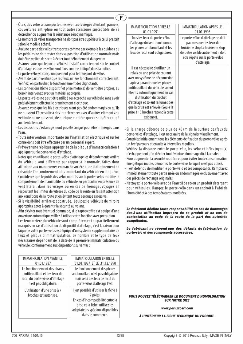
- Les feux arrière du véhicule sont complètement ou par tiellement masqués en cas d'utilisation du dispositif d'attelage, c'est la raison pour laquelle votre porte-vélos est équipé d'un système supplémentaire de feux et plaque d'immatriculation. Le nombre et le type de feux nécessaires dépendent de la date de la première immatriculation du véhicule, conformément aux dispositions suivantes :
- Si la charge déborde de plus de 40 cm de la surface des feux du porte-vélos d'attelage, il est nécessaire de la signaler visuellement.
- Contrôlez initialement tous les éléments de fixation du porte-vélos après un bref parcours et ensuite à intervalles réguliers.
- Vérifiez la distance entre le porte-vélo, les vélos et le/les tuyau(x) d'échappement afin d'éviter tout éventuel dommage dû à la chaleur.
- Pour augmenter la sécurité routière et pour éviter toute consommation énergétique inutile, démontez le porte-vélos lorsqu'il n'est pas utilisé.
- Il est défendu de modifier le porte-vélo et ses composants. Remplacez immédiatement toute partie usée ou endommagée exclusivement avec des pièces de rechange originales.
- Nettoyez le porte-vélo avec de l’eau tiède et/ou un produit détergent pour véhicules. Rangez le porte-vélo dans un endroit à l’abri de l’humidité et à des températures modérées.
Le fabricant décline toute responsabilité en cas de dommages dus à une utilisation impropre de ce produit et en cas de contestation au code de la route de la part des autorités compétentes.
Le fabricant ne répond que des défauts de fabrication du porte-vélo et des composants accessoires.
VOUS POUVEZ TÉLÉCHARGER LE DOCUMENT D’HOMOLOGATION SUR NOTRE SITE
www.peruzzosrl.com
À L’INTÉRIEUR LA FICHE TECHNIQUE DU PRODUIT.
Le fonctionnement des phares antibrouillard et des feux de
recul du porte-vélos d'attelage n'est pas obligatoire.
L'utilisation d'une prise à 7 broches est autorisée.
IMMATRICULATION AVANT LE 01.01.1987
Le fonctionnement des phares antibrouillard n'est pas obligatoire
mais celui des feux de recul du porte-vélos d'attelage l'est.
Il est possible d’utiliser la fiche à 7 pôles.
En cas d'incompatibilité entre la prise et la fiche, utilisez les
adaptateurs spéciaux disponibles dans le commerce.
IMMATRICULATION ENTRE LE 01.01.1987 ET LE 31.12.1990
Il est nécessaire d'utiliser un relais ou une prise de courant
avec un système de déconnexion apte à garantir que les phares
antibrouillard du véhicule soient éteints automatiquement en cas
d'utilisation du crochet d'attelage et soient rallumés dès que la prise est enlevée (Seule la prise à 13 broches répond à cette
exigence).
Tous les feux du porte-vélos d'attelage doivent fonctionner. Les phares antibrouillard et les feux de recul sont obligatoires.
IMMATRICULATION APRES LE 01.01.1991
IMMATRICULATION APRES LE 01.01.1998
Le porte-vélos d'attelage ne doit pas masquer les feux du
troisième stop.Le troisième stop doit être visible autrement il doit
être répété sur le porte-vélos d'attelage.

706_PARMA_31/01/15 14/28 Copyright © 2012 Peruzzo Italy - MADE IN ITALY
IISTRUZIONI PER IL MONTAGGIO E L'IMPIEGOOgni volta che si usa questo prodotto devono essere considerate le informazioni sotto riportate: il portaciclo è un prodotto sicuro se usato correttamente, al contrario, se usato male, può arrecare danni a Voi e ad altri che vi seguono in strada.
1) Inserire i tappi 1 nei tubi quadri portanti 2 (Fig. A).2) Inserire i tappi 3 negli archi portanti 4 (Fig. A) e nell’arco di fissaggio 5
(Fig. D2).3) Montare gli alloggiamenti ruota 6 all'arco portante 4 nelle posizioni più
adatte alle dimensioni della vostra bicicletta fissandoli con le viti 7, i dadi e le rondelle 8 (Fig. A).
4) Fissare il gancio 9 ai dispositivi di inclinazione 10 (Fig. A).5) Montare i fanali posteriori 11 sulla barra portafanali 12 fissandoli con
le rondelle e i dadi 13 (Fig. B) attenzione a non danneggiare i cavi e a non serrare in modo eccessivo i dadi in quanto si potrebbero danneg- giare le par ti in plastica. Aver cura di far passare la spina a 13 poli all'interno del foro centrale della barra portafanali 12.
6) Montare il portatarga 14 alla barra portafanali 12 fissandola con le viti 15 (Fig. B).
7) Montare il gruppo barra portafanali 12 al tubo quadro 16 fissandolo con le viti 17, i dadi e le rondelle 18, facendo attenzione che il gancio di inclinazione 9 si infili nella feritoia predisposta (Fig. C).
8) Montaggio arco di fissaggio 5:- Svitare e togliere i pomelli 19 e le rondelle 20 da entrambi i lati (Fig. D1);- Eseguire le operazioni 1, 2 (solo per art. 706/4) e 3 (Fig. D2);- Inserire l’arco di fissaggio 5 nella sede delle ruote di regolazione 21, quindi fissarlo con le rondelle 20 e i pomelli 19 (Fig. D2).
Per il montaggio in sicurezza del portaciclo e per evitare danni al veicolo si consiglia di richiedere l’aiuto di un’altra persona.
9) Azionare la leva 22 verso l'alto, per sbloccarla girare la chiave 23 in senso antiorario (Fig. E1).
10) Appoggiare il blocco di fissaggio 24 alla sfera del gancio traino 25 (Fig. E2).
11) Il dispositivo di fissaggio si chiude abbassando la leva 22: la forza di chiusura deve essere pari ad almeno 45 Kg. (Fig. E2).
Regolazione della forza di chiusura della manoE’ sempre necessario effettuare la prima regolazione al momento dell’acquisto del prodotto. Successivamente il controllo della forza di chiusura deve essere effettuato ad ogni utilizzo procedendo nuovamente con la regolazione nel caso in cui fosse necessario. Al fine di prevenire incidenti e danni è opportuno richiedere, anche in questa fase, l'aiuto di un'altra persona. Dopo aver sbloccato e alzato la leva 22 il portaciclo deve essere mantenuto in posizione orizzontale dalla seconda persona. La vite 26 deve essere regolata con la chiave in dotazione 27 in modo tale che la forza di chiusura sulla leva venga aumentata fino ad un minimo di 45 Kg. (Fig. E2). Assicurarsi che, con il dispositivo di fissaggio chiuso, il portaciclo non ruoti.
SOLO PER ART.706/412) Inserire i ganci delle cinghie 35 ai bordi del portellone dell'autoveicolo,
quindi inserire le cinghie nelle fibbie 34 facendo attenzione al giusto verso di entrata (Fig. F).IMPORTANTE : Verificare la tenuta delle cinghie strattonandole. Controllarne la tensione all'inizio del viaggio e durante le soste.
COME INSTALLARE IL PORTACICLO SUL GANCIO DI TRAINO
13) Posizionare sul por taciclo per prima la bicicletta più grande e più pesante, mettere le ruote negli alloggiamenti ruota 6 ed appoggiarla contro l’arco di fissaggio 5. Fissare la bici con la cinghia di fissaggio 28 al l ’arco di fissaggio 5 (Fig. H1 ). Fissare le ruote con le cinghie di fissaggio 29 (Fig. G).
POSIZIONAMENTO E FISSAGGIO DELLE BICICLETTE SUL PORTACICLO
INCLINAZIONE DEL PORTACICLO (Fig. I/L/M)Per inclinare il portabici tenerlo sollevato con una mano mentre con l’altra tirare il gancio 9 (Fig. I). Per evitare lesioni e danni l’inclinazio- ne del portaciclo da parte dell’operatore dovrebbe essere effettuata facendosi aiutare da una terza persona. Per la chiusura il portaciclo viene sollevato fino a quando il dispositivo di inclinazione 10 si innesta completamente passando dalla posizione di inclinazione (Fig. L) alla posizione di chiusura (Fig. M).
14) Ripetere le operazioni 13) per la seconda, la terza e la quarta bicicletta. La seconda e la terza bicicletta sono fissate all’arco di fissaggio 5 con i braccetti di fissaggio 30/31 (Fig. H1), mentre la quarta è fissata alla terza con il braccetto di fissaggio 32 (Fig. H2).IMPORTANTE: Per trasportare in sicurezza il carico il portabici è fornito della cinghia 33 che deve legare tutte le bici al l ’arco di fissaggio 5. Assicurarsi, tendendo sufficientemente la cinghia, che essa sia montata correttamente.
Oltre a quanto di seguito esposto preghiamo di osservare "Condi- zioni, consigli e limitazioni d’uso" di cui al certificato di prova per l’omologazione CE del tipo.
- Peso proprio dei portacicli "PARMA" e portata massima:* Modello 706/4 (20,03 kg.) ---> 4 biciclette, portata max. 60 kg.* Modello 706/3 (17,38 kg.) ---> 3 biciclette, portata max. 60 kg.* Modello 706/3A (15,77 kg.) ---> 3 biciclette, portata max. 60 kg.* Modello 706 (15,58 kg.) ---> 2 biciclette, portata max. 60 kg.
- Non superare mai la portata consentita del gancio di traino installato. I l peso complessivo del por taciclo e del carico non devono mai superare la portata consentita. Mantenere la superficie della sfera del gancio di traino pulita eliminando eventuali tracce di sporco o olio.
- Il conducente è sempre responsabile del carico trasportato e quindi anche di effettuare un controllo al fine di verificarne l’adeguato fissaggio sia al momento della partenza, sia durante il viaggio ad intervalli regolari.
- Consultare il manuale dell’auto e verificare il rispetto delle specifiche riportate in merito al carico massimo consentito sull’asse posteriore.
- Verificare il rispetto del valore D (portata massima) del gancio traino indicato dal produttore dell’auto o del gancio traino; il valore D espresso per il gancio traino dovrebbe essere pari ad almeno (760 Kg)7,6 KN; i ganci traino più vecchi spesso indicano solamente il carico consentito sul gancio traino GA ed il carico totale consentito del veicolo trainante GK anziché il valore D; in tal caso il valore D può essere così calcolato prendendo i valori nel libretto di manutenzione della vettura o nel libretto di immatricolazione:
- Togliere dalle biciclette trasportate eventuali seggiolini per bambini,
cestini, coperture per pioggia o qualsiasi altro elemento che potrebbe staccarsi o aumentare la resistenza aerodinamica.
- Il numero di biciclette trasportate non deve superare quello previsto in base al modello acquistato.
- Nessuna parte delle biciclette caricate come, per esempio, manubri o pedali, devono essere lasciati in posizione di utilizzo classico, vanno piegati onde evitare sporgenze pericolose.
- Assicurarsi che il portaciclo sia montato correttamente sul gancio di traino e che le biciclette siano fissate come da istruzioni fornite.
- Il portaciclo è idoneo solo per il trasporto di biciclette.
ATTENZIONE - NORME DI SICUREZZA
D = x9,81 (GA x GK)
1000 (GA + GK)(D in [kN] / GA in [kg] / GK in [kg])

706_PARMA_31/01/15 15/28 Copyright © 2012 Peruzzo Italy - MADE IN ITALY
I- Prima di partire controllare la completa funzionalità delle luci posteriori;
verificare, in particolare, il funzionamento delle frecce direzionali.- Mantenere pulite le connessioni (spina dispositivo e presa motrice),
intervenendo con materiali appropriati ove si rendesse necessario.- Non utilizzare e/o agganciare il portabici all’auto senza aver prima
effettuato il collegamento elettrico.- Verificare che i cavi elettrici non siano danneggiati o possano esserlo per
interferenze con altri elementi del veicolo o possano, in qualche modo, essere tranciati accidentalmente.
- I dispositivi di illuminazioni non sono progettati per essere immersi in acqua.
- Eventuali interventi rilevanti sull’impianto elettrico e sulle connessioni devono essere eseguiti da personale specializzato.
- Provvedere con un’adeguata replica della targa da applicare sul portabici gancio traino.
- Tenere presente che con l ’ut i l izzo del por tabic i gancio t ra ino le sporgenze posteriori del veicolo sono diverse rispetto al normale, fate, quindi, attenzione alle manovre di retromarcia e di parcheggio per il maggior ingombro in lunghezza dell’autoveicolo, considerare che il peso delle biciclette caricate sul portaciclo cambia il comportamento della guidabilità dell’auto soprattutto in presenza di vento laterale, in curva o in caso di frenata; viaggiare rispettando i limiti di velocità del codice stradale prestando attenzione alle condizioni della strada ed evitando scossoni.
- Se la visuale posteriore risulta ostruita equipaggiare il veicolo con adeguati specchietti retrovisori che garantiscano una guida in sicurezza.
- Al fine di evitare danni, se il cofano/portellone è provvisto di apertura automatica, dovete utilizzare questa funzione con molta attenzione.
- Le luci posteriori dell’auto vengono completamente o parzialmente oscurate in caso di utilizzo del dispositivo gancio traino, per questo motivo il portabici che avete acquistato è dotato di un ulteriore sistema di luci e targa. Il numero e la tipologia di luci necessarie dipendono dalla data di prima immatricolazione del veicolo secondo quanto segue:
- Se il carico proietta più di 40 cm oltre la superficie delle luci del porta- bici gancio traino allora è necessario segnalarlo visivamente.
- Controllare, inizialmente dopo un breve percorso, e successivamente a intervalli regolari, tutti gli elementi di fissaggio del portaciclo.
- Verificare la distanza tra il portaciclo, le biciclette e il/i tubo/i di scarico per evitare eventuali danni imputabili al calore.
- Per aumentare la sicurezza stradale e per un corretto risparmio ener- getico smontare il portaciclo quando non viene utilizzato.
- E’ vietato modificare il por taciclo ed i suoi componenti. Sostituire immediatamente qualsiasi parte usurata o danneggiata esclusivamente con ricambi originali.
- La pulizia del portaciclo può essere eseguita con acqua tiepida e/o un prodotto detergente per auto. Riporre il por taciclo a temperature moderate ed al riparo dall’umidità.
Il fabbricante non è responsabile dei danni causati dal cattivo uso di questo prodotto, né dell’eventuale contestazione al codice della strada da parte delle autorità competenti.
Il fabbricante è responsabile solo dei difetti di fabbricazione del portaciclo e componenti accessori.
E’ POSSIBILE SCARICARE IL DOCUMENTO DI OMOLOGAZIONE DAL NOSTRO SITO
www.peruzzosrl.com
ALL’INTERNO DELLA SCHEDA TECNICA DEL PRODOTTO.
Non è obbligatorio il funziona- mento delle luci fendinebbia e delle luci di retromarcia del por- tabici gancio traino.
E’ consentito l’uso di una spina a 7 poli.
IMMATRICOLAZIONE PRIMA DEL01.01.1987
Non è obbligatorio il funziona- mento delle luci fendinebbia ma è obbligatorio il funzionamento delle luci di retromarcia del por- tabici gancio traino.
E’ consentito l’uso della spina a 7 poli. In caso di incompatibilità tra presa e spina util izzare gli appositi adattatori che si trovano in commercio.
IMMATRICOLAZIONE TRA IL 01.01.1987 ED IL 31.12.1990
Tutte le luci del portabici gancio traino devono essere funzionan- ti. Luci fendinebbia e luci di re- tromarcia sono obbligatorie.
E’ necessario l’utilizzo di un relè o di una presa elettrica con un sistema di sconnessione che as- sicuri che le luci fendinebbia del veicolo vengano spente automa- ticamente in caso di utilizzo del gancio traino e che vengano riaccese non appena viene ri- mossa la spina (Solo la spina a 13 poli risponde a tale requisito).
IMMATRICOLAZIONE DOPO IL01.01.1991
IMMATRICOLAZIONE DOPO IL01.01.1998
Il portabici gancio traino non deve coprire le luci del terzo stop. Il terzo stop deve essere visibile in caso contrario deve es- sere ripetuto sul portabici gancio traino.
706_PARMA_31/01/15 16/28 Copyright © 2012 Peruzzo Italy - MADE IN ITALY
E
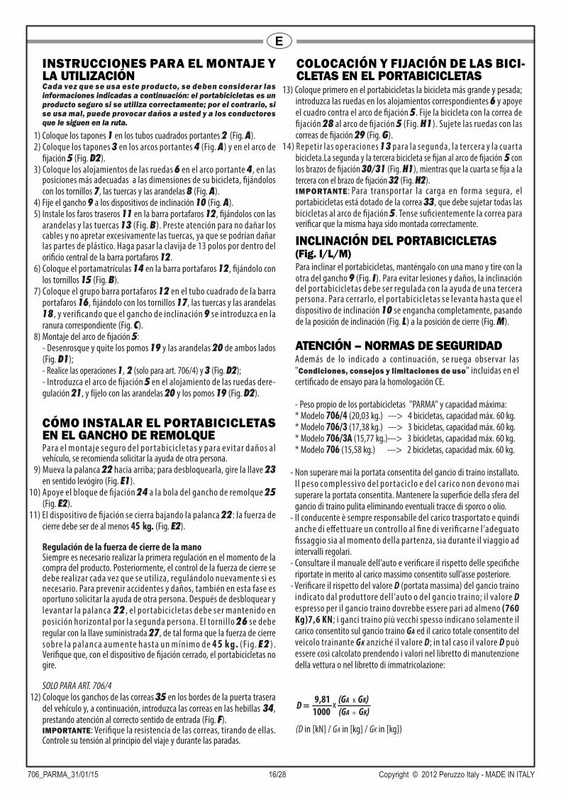
INSTRUCCIONES PARA EL MONTAJE Y LA UTILIZACIÓNCada vez que se usa este producto, se deben considerar las informaciones indicadas a continuación: el portabicicletas es un producto seguro si se utiliza correctamente; por el contrario, si se usa mal, puede provocar daños a usted y a los conductores que le siguen en la ruta.
1) Coloque los tapones 1 en los tubos cuadrados portantes 2 (Fig. A).2) Coloque los tapones 3 en los arcos portantes 4 (Fig. A) y en el arco de
fijación 5 (Fig. D2).3) Coloque los alojamientos de las ruedas 6 en el arco portante 4, en las
posiciones más adecuadas a las dimensiones de su bicicleta, fijándolos con los tornillos 7, las tuercas y las arandelas 8 (Fig. A).
4) Fije el gancho 9 a los dispositivos de inclinación 10 (Fig. A).5) Instale los faros traseros 11 en la barra portafaros 12, fijándolos con las
arandelas y las tuercas 13 (Fig. B). Preste atención para no dañar los cables y no apretar excesivamente las tuercas, ya que se podrían dañar las partes de plástico. Haga pasar la clavija de 13 polos por dentro del orificio central de la barra portafaros 12.
6) Coloque el portamatrículas 14 en la barra portafaros 12, fijándolo con los tornillos 15 (Fig. B).
7) Coloque el grupo barra portafaros 12 en el tubo cuadrado de la barra portafaros 16, fijándolo con los tornillos 17, las tuercas y las arandelas 18 , y verificando que el gancho de inclinación 9 se introduzca en la ranura correspondiente (Fig. C).
8) Montaje del arco de fijación 5:- Desenrosque y quite los pomos 19 y las arandelas 20 de ambos lados (Fig. D1);- Realice las operaciones 1, 2 (solo para art. 706/4) y 3 (Fig. D2);- Introduzca el arco de fijación 5 en el alojamiento de las ruedas dere- gulación 21, y fíjelo con las arandelas 20 y los pomos 19 (Fig. D2).
Para el montaje seguro del por tabicicletas y para evitar daños al vehículo, se recomienda solicitar la ayuda de otra persona.
9) Mueva la palanca 22 hacia arriba; para desbloquearla, gire la llave 23 en sentido levógiro (Fig. E1).
10) Apoye el bloque de fijación 24 a la bola del gancho de remolque 25 (Fig. E2).
11) El dispositivo de fijación se cierra bajando la palanca 22: la fuerza de cierre debe ser de al menos 45 kg. (Fig. E2).
Regulación de la fuerza de cierre de la manoSiempre es necesario realizar la primera regulación en el momento de la compra del producto. Posteriormente, el control de la fuerza de cierre se debe realizar cada vez que se utiliza, regulándolo nuevamente si es necesario. Para prevenir accidentes y daños, también en esta fase es oportuno solicitar la ayuda de otra persona. Después de desbloquear y levantar la palanca 22 , el por tabicicletas debe ser mantenido en posición horizontal por la segunda persona. El tornillo 26 se debe regular con la llave suministrada 27, de tal forma que la fuerza de cierre sobre la palanca aumente hasta un mínimo de 45 kg. (Fig. E2 ) . Verifique que, con el dispositivo de fijación cerrado, el portabicicletas no gire.
SOLO PARA ART. 706/412) Coloque los ganchos de las correas 35 en los bordes de la puerta trasera
del vehículo y, a continuación, introduzca las correas en las hebillas 34, prestando atención al correcto sentido de entrada (Fig. F).IMPORTANTE: Verifique la resistencia de las correas, tirando de ellas. Controle su tensión al principio del viaje y durante las paradas.
CÓMO INSTALAR EL PORTABICICLETAS EN EL GANCHO DE REMOLQUE
COLOCACIÓN Y FIJACIÓN DE LAS BICI- CLETAS EN EL PORTABICICLETAS
INCLINACIÓN DEL PORTABICICLETAS(Fig. I/L/M)Para inclinar el portabicicletas, manténgalo con una mano y tire con la otra del gancho 9 (Fig. I). Para evitar lesiones y daños, la inclinación del portabicicletas debe ser regulada con la ayuda de una tercera persona. Para cerrarlo, el portabicicletas se levanta hasta que el dispositivo de inclinación 10 se engancha completamente, pasando de la posición de inclinación (Fig. L) a la posición de cierre (Fig. M).
13) Coloque primero en el portabicicletas la bicicleta más grande y pesada; introduzca las ruedas en los alojamientos correspondientes 6 y apoye el cuadro contra el arco de fijación 5. Fije la bicicleta con la correa de fijación 28 al arco de fijación 5 (Fig. H1). Sujete las ruedas con las correas de fijación 29 (Fig. G).
14) Repetir las operaciones 13 para la segunda, la tercera y la cuar ta bicicleta.La segunda y la tercera bicicleta se fijan al arco de fijación 5 con los brazos de fijación 30/31 (Fig. H1), mientras que la cuarta se fija a la tercera con el brazo de fijación 32 (Fig. H2).IMPORTANTE : Para transportar la carga en forma segura, el portabicicletas está dotado de la correa 33, que debe sujetar todas las bicicletas al arco de fijación 5. Tense suficientemente la correa para verificar que la misma haya sido montada correctamente.
Además de lo indicado a continuación, se ruega observar las "Condiciones, consejos y limitaciones de uso" incluidas en el certificado de ensayo para la homologación CE.
- Peso propio de los portabicicletas "PARMA" y capacidad máxima:* Modelo 706/4 (20,03 kg.) ---> 4 bicicletas, capacidad máx. 60 kg.* Modelo 706/3 (17,38 kg.) ---> 3 bicicletas, capacidad máx. 60 kg.* Modelo 706/3A (15,77 kg.)---> 3 bicicletas, capacidad máx. 60 kg.* Modelo 706 (15,58 kg.) ---> 2 bicicletas, capacidad máx. 60 kg.
- Non superare mai la portata consentita del gancio di traino installato. I l peso complessivo del por taciclo e del carico non devono mai superare la portata consentita. Mantenere la superficie della sfera del gancio di traino pulita eliminando eventuali tracce di sporco o olio.
- Il conducente è sempre responsabile del carico trasportato e quindi anche di effettuare un controllo al fine di verificarne l’adeguato fissaggio sia al momento della partenza, sia durante il viaggio ad intervalli regolari.
- Consultare il manuale dell’auto e verificare il rispetto delle specifiche riportate in merito al carico massimo consentito sull’asse posteriore.
- Verificare il rispetto del valore D (portata massima) del gancio traino indicato dal produttore dell’auto o del gancio traino; il valore D espresso per il gancio traino dovrebbe essere pari ad almeno (760 Kg)7,6 KN; i ganci traino più vecchi spesso indicano solamente il carico consentito sul gancio traino GA ed il carico totale consentito del veicolo trainante GK anziché il valore D; in tal caso il valore D può essere così calcolato prendendo i valori nel libretto di manutenzione della vettura o nel libretto di immatricolazione:
ATENCIÓN – NORMAS DE SEGURIDAD
D = x9,81 (GA x GK)
1000 (GA + GK)
(D in [kN] / GA in [kg] / GK in [kg])
706_PARMA_31/01/15 17/28 Copyright © 2012 Peruzzo Italy - MADE IN ITALY
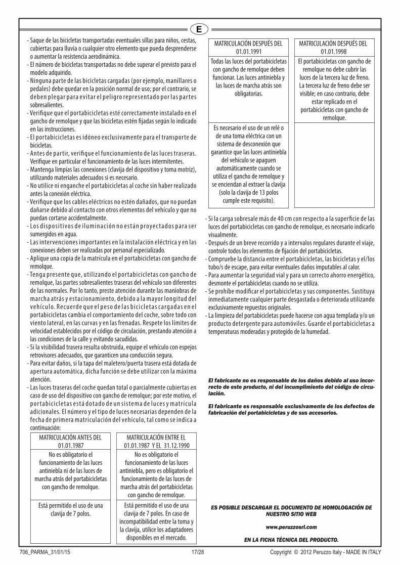
E- Saque de las bicicletas transportadas eventuales sillas para niños, cestas,
cubiertas para lluvia o cualquier otro elemento que pueda desprenderse o aumentar la resistencia aerodinámica.
- El número de bicicletas transportadas no debe superar el previsto para el modelo adquirido.
- Ninguna parte de las bicicletas cargadas (por ejemplo, manillares o pedales) debe quedar en la posición normal de uso; por el contrario, se deben plegar para evitar e l pel igro representado por las par tes sobresalientes.
- Verifique que el portabicicletas esté correctamente instalado en el gancho de remolque y que las bicicletas estén fijadas según lo indicado en las instrucciones.
- El por tabicicletas es idóneo exclusivamente para el transpor te de bicicletas.
- Antes de par tir, verifique el funcionamiento de las luces traseras. Verifique en particular el funcionamiento de las luces intermitentes.
- Mantenga limpias las conexiones (clavija del dispositivo y toma motriz), utilizando materiales adecuados si es necesario.
- No utilice ni enganche el portabicicletas al coche sin haber realizado antes la conexión eléctrica.
- Verifique que los cables eléctricos no estén dañados, que no puedan dañarse debido al contacto con otros elementos del vehículo y que no puedan cortarse accidentalmente.
- Lo s d i s p o s i t i vo s d e i l u m i n a c i ó n n o e s t á n p roye c t a d o s p a ra s e r sumergidos en agua.
- Las intervenciones importantes en la instalación eléctrica y en las conexiones deben ser realizadas por personal especializado.
- Aplique una copia de la matrícula en el portabicicletas con gancho de remolque.
- Tenga presente que, uti l izando el por tabicicletas con gancho de remolque, las partes sobresalientes traseras del vehículo son diferentes de las normales. Por lo tanto, preste atención durante las maniobras de marcha atrás y estacionamiento, debido a la mayor longitud del ve h í c u l o. R e c u e rd e q u e e l p e s o d e l a s b i c i c l e t a s c a rg a d a s e n e l portabicicletas cambia el comportamiento del coche, sobre todo con viento lateral, en las curvas y en las frenadas. Respete los límites de velocidad establecidos por el código de circulación, prestando atención a las condiciones de la calle y evitando sacudidas.
- Si la visibilidad trasera resulta obstruida, equipe el vehículo con espejos retrovisores adecuados, que garanticen una conducción segura.
- Para evitar daños, si la tapa del maletero/puerta trasera está dotada de apertura automática, dicha función se debe utilizar con la máxima atención.
- Las luces traseras del coche quedan total o parcialmente cubiertas en caso de uso del dispositivo con gancho de remolque; por este motivo, el p o r t a b i c i c l e t a s e s t á d o t a d o d e u n s i s te m a d e l u ce s y m at r í c u l a adicionales. El número y el tipo de luces necesarias dependen de la fecha de primera matriculación del vehículo, tal como se indica a continuación:
- Si la carga sobresale más de 40 cm con respecto a la superficie de las luces del portabicicletas con gancho de remolque, es necesario indicarlo visualmente.
- Después de un breve recorrido y a intervalos regulares durante el viaje, controle todos los elementos de fijación del portabicicletas.
- Compruebe la distancia entre el portabicicletas, las bicicletas y el/los tubo/s de escape, para evitar eventuales daños imputables al calor.
- Para aumentar la seguridad vial y para un correcto ahorro energético, desmonte el portabicicletas cuando no se utiliza.
- Se prohíbe modificar el portabicicletas y sus componentes. Sustituya inmediatamente cualquier parte desgastada o deteriorada utilizando exclusivamente repuestos originales.
- La limpieza del portabicicletas puede hacerse con agua templada y/o un producto detergente para automóviles. Guarde el portabicicletas a temperaturas moderadas y protegido de la humedad.
El fabricante no es responsable de los daños debido al uso incor- recto de este producto, ni del incumplimiento del código de circu- lación.
El fabricante es responsable exclusivamente de los defectos de fabricación del portabicicletas y de sus accesorios.
ES POSIBLE DESCARGAR EL DOCUMENTO DE HOMOLOGACIÓN DE NUESTRO SITIO WEB
www.peruzzosrl.com
EN LA FICHA TÉCNICA DEL PRODUCTO.
No es obligatorio el funcionamiento de las luces antiniebla ni de las luces de
marcha atrás del portabicicletas con gancho de remolque.
Está permitido el uso de una clavija de 7 polos.
MATRICULACIÓN ANTES DEL 01.01.1987
No es obligatorio el funcionamiento de las luces
antiniebla, pero es obligatorio el funcionamiento de las luces de marcha atrás del portabicicletas
con gancho de remolque.
Está permitido el uso de una clavija de 7 polos. En caso de
incompatibilidad entre la toma y la clavija, utilice los adaptadores
disponibles en el mercado.
MATRICULACIÓN ENTRE EL 01.01.1987 Y EL 31.12.1990
Todas las luces del portabicicletas con gancho de remolque deben funcionar. Las luces antiniebla y
las luces de marcha atrás son obligatorias.
Es necesario el uso de un relé o de una toma eléctrica con un sistema de desconexión que
garantice que las luces antiniebla del vehículo se apaguen
automáticamente cuando se utiliza el gancho de remolque y se enciendan al extraer la clavija
(solo la clavija de 13 polos cumple este requisito).
MATRICULACIÓN DESPUÉS DEL 01.01.1991
MATRICULACIÓN DESPUÉS DEL 01.01.1998
El portabicicletas con gancho de remolque no debe cubrir las
luces de la tercera luz de freno. La tercera luz de freno debe ser visible; en caso contrario, debe
estar replicado en el portabicicletas con gancho de
remolque.
706_PARMA_31/01/15 18/28 Copyright © 2012 Peruzzo Italy - MADE IN ITALY
PL
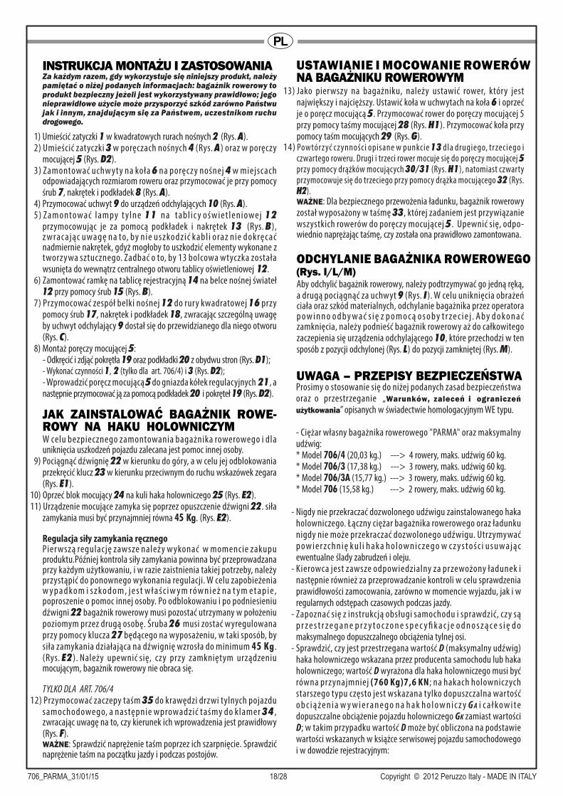
INSTRUKCJA MONTAŻU I ZASTOSOWANIAZa każdym razem, gdy wykorzystuje się niniejszy produkt, należy pamiętać o niżej podanych informacjach: bagażnik rowerowy to produkt bezpieczny jeżeli jest wykorzystywany prawidłowo; jego nieprawidłowe użycie może przysporzyć szkód zarówno Państwu jak i innym, znajdującym się za Państwem, uczestnikom ruchu drogowego.
1) Umieścić zatyczki 1 w kwadratowych rurach nośnych 2 (Rys. A).2) Umieścić zatyczki 3 w poręczach nośnych 4 (Rys. A) oraz w poręczy
mocującej 5 (Rys. D2).3) Zamontować uchw yty na koła 6 na poręczy nośnej 4 w miejscach
odpowiadających rozmiarom roweru oraz przymocować je przy pomocy śrub 7, nakrętek i podkładek 8 (Rys. A).
4) Przymocować uchwyt 9 do urządzeń odchylających 10 (Rys. A).5) Zamontować lampy t y lne 11 na tabl ic y oświet leniowej 12
przymocowując je za pomocą podkładek i nakrętek 13 (Rys. B), z wracając uwagę na to, by nie uszkodzić kabl i oraz nie dokręcać nadmiernie nakrętek, gdyż mogłoby to uszkodzić elementy wykonane z tworzywa sztucznego. Zadbać o to, by 13 bolcowa wtyczka została wsunięta do wewnątrz centralnego otworu tablicy oświetleniowej 12.
6) Zamontować ramkę na tablicę rejestracyjną 14 na belce nośnej świateł 12 przy pomocy śrub 15 (Rys. B).
7) Przymocować zespół belki nośnej 12 do rury kwadratowej 16 przy pomocy śrub 17, nakrętek i podkładek 18, zwracając szczególną uwagę by uchwyt odchylający 9 dostał się do przewidzianego dla niego otworu (Rys. C).
8) Montaż poręczy mocującej 5:- Odkręcić i zdjąć pokrętła 19 oraz podkładki 20 z obydwu stron (Rys. D1);- Wykonać czynności 1, 2 (tylko dla art. 706/4) i 3 (Rys. D2);
- Wprowadzić poręcz mocującą 5 do gniazda kółek regulacyjnych 21, a następnie przymocować ją za pomocą podkładek 20 i pokręteł 19 (Rys. D2).
W celu bezpiecznego zamontowania bagażnika rowerowego i dla uniknięcia uszkodzeń pojazdu zalecana jest pomoc innej osoby.
9) Pociągnąć dźwignię 22 w kierunku do góry, a w celu jej odblokowania przekręcić klucz 23 w kierunku przeciwnym do ruchu wskazówek zegara (Rys. E1).
10) Oprzeć blok mocujący 24 na kuli haka holowniczego 25 (Rys. E2).11) Urządzenie mocujące zamyka się poprzez opuszczenie dźwigni 22. siła
zamykania musi być przynajmniej równa 45 Kg. (Rys. E2).
Regulacja siły zamykania ręcznegoPier wszą regulację zawsze należy w ykonać w momencie zakupu produktu.Później kontrola siły zamykania powinna być przeprowadzana przy każdym użytkowaniu, i w razie zaistnienia takiej potrzeby, należy przystąpić do ponownego wykonania regulacji. W celu zapobieżenia w y p a d ko m i s z ko d o m , j e s t w ł a ś c i w y m ró w n i e ż n a t y m e t a p i e, poproszenie o pomoc innej osoby. Po odblokowaniu i po podniesieniu dźwigni 22 bagażnik rowerowy musi pozostać utrzymany w położeniu poziomym przez drugą osobę. Śruba 26 musi zostać wyregulowana przy pomocy klucza 27 będącego na wyposażeniu, w taki sposób, by siła zamykania działająca na dźwignię wzrosła do minimum 45 Kg. (Rys. E2 ). Należy upewnić się, czy przy zamkniętym urządzeniu mocującym, bagażnik rowerowy nie obraca się.
TYLKO DLA ART. 706/412) Przymocować zaczepy taśm 35 do krawędzi drzwi tylnych pojazdu
samochodowego, a następnie wprowadzić taśmy do klamer 34 , zwracając uwagę na to, czy kierunek ich wprowadzenia jest prawidłowy (Rys. F). WAŻNE: Sprawdzić naprężenie taśm poprzez ich szarpnięcie. Sprawdzić naprężenie taśm na początku jazdy i podczas postojów.
JAK ZAINSTALOWAĆ BAGAŻNIK ROWE- ROWY NA HAKU HOLOWNICZYM
ODCHYLANIE BAGAŻNIKA ROWEROWEGO (Rys. I/L/M)Aby odchylić bagażnik rowerowy, należy podtrzymywać go jedną ręką, a drugą pociągnąć za uchwyt 9 (Rys. I). W celu uniknięcia obrażeń ciała oraz szkód materialnych, odchylanie bagażnika przez operatora p o w i n n o o d b y w a ć s i ę z p o m o c ą o s o b y t r ze c i e j . A b y d o ko n a ć zamknięcia, należy podnieść bagażnik rowerowy aż do całkowitego zaczepienia się urządzenia odchylającego 10, które przechodzi w ten sposób z pozycji odchylonej (Rys. L) do pozycji zamkniętej (Rys. M).
13) Jako pierwszy na bagażniku, należy ustawić rower, który jest największy i najcięższy. Ustawić koła w uchwytach na koła 6 i oprzeć je o poręcz mocującą 5. Przymocować rower do poręczy mocującej 5 przy pomocy taśmy mocującej 28 (Rys. H1). Przymocować koła przy pomocy taśm mocujących 29 (Rys. G).
14) Powtórzyć czynności opisane w punkcie 13 dla drugiego, trzeciego i czwartego roweru. Drugi i trzeci rower mocuje się do poręczy mocującej 5 przy pomocy drążków mocujących 30/31 (Rys. H1), natomiast czwarty przymocowuje się do trzeciego przy pomocy drążka mocującego 32 (Rys. H2). WAŻNE: Dla bezpiecznego przewożenia ładunku, bagażnik rowerowy został wyposażony w taśmę 33, której zadaniem jest przywiązanie wszystkich rowerów do poręczy mocującej 5 . Upewnić się, odpo- wiednio naprężając taśmę, czy została ona prawidłowo zamontowana.
Prosimy o stosowanie się do niżej podanych zasad bezpieczeństwa oraz o przestrzeganie „Warunków, zaleceń i ograniczeń użytkowania” opisanych w świadectwie homologacyjnym WE typu.
- Ciężar własny bagażnika rowerowego "PARMA" oraz maksymalny udźwig:* Model 706/4 (20,03 kg.) ---> 4 rowery, maks. udźwig 60 kg.* Model 706/3 (17,38 kg.) ---> 3 rowery, maks. udźwig 60 kg.* Model 706/3A (15,77 kg.) ---> 3 rowery, maks. udźwig 60 kg.* Model 706 (15,58 kg.) ---> 2 rowery, maks. udźwig 60 kg.
- Nigdy nie przekraczać dozwolonego udźwigu zainstalowanego haka holowniczego. Łączny ciężar bagażnika rowerowego oraz ładunku nigdy nie może przekraczać dozwolonego udźwigu. Utrzymywać p ow i e r zc h n i ę k u l i h a k a h o l ow n i c ze g o w c z y s to ś c i u s u wa j ą c ewentualne ślady zabrudzeń i oleju.
- Kierowca jest zawsze odpowiedzialny za przewożony ładunek i następnie również za przeprowadzanie kontroli w celu sprawdzenia prawidłowości zamocowania, zarówno w momencie wyjazdu, jak i w regularnych odstępach czasowych podczas jazdy.
- Zapoznać się z instrukcją obsługi samochodu i sprawdzić, czy są p r z e s t r z e g a n e p r z y t o c z o n e s p e c y fi k a c j e o d n o s z ą c e s i ę d o maksymalnego dopuszczalnego obciążenia tylnej osi.
- Sprawdzić, czy jest przestrzegana wartość D (maksymalny udźwig) haka holowniczego wskazana przez producenta samochodu lub haka holowniczego; wartość D wyrażona dla haka holowniczego musi być równa przynajmniej (760 Kg)7,6 KN; na hakach holowniczych starszego typu często jest wskazana tylko dopuszczalna wartość o b c i ą ż e n i a w y w i e r a n e g o n a h a k h o l o w n i c z y G A i c a ł ko w i t e dopuszczalne obciążenie pojazdu holowniczego GK zamiast wartości D; w takim przypadku wartość D może być obliczona na podstawie wartości wskazanych w książce serwisowej pojazdu samochodowego i w dowodzie rejestracyjnym:
USTAWIANIE I MOCOWANIE ROWERÓW NA BAGAŻNIKU ROWEROWYM
UWAGA – PRZEPISY BEZPIECZEŃSTWA
706_PARMA_31/01/15 19/28 Copyright © 2012 Peruzzo Italy - MADE IN ITALY
PL
- Zdjąć z przewożonych rowerów ewentualne foteliki dla dzieci, kosze, pokrowce przeciwdeszczowe oraz wszelkie inne elementy mogące ulec oderwaniu się lub zwiększające opór powietrza.
- I lość t ranspor towanych rowerów nie może być w yższa od i lośc i przewidzianej dla zakupionego modelu.
- Żadna z części załadowanych rowerów, jak np. kierownica lub pedały, nie mogą być pozostawione w klasycznym położeniu do użytkowania, lecz powinny zostać złożone, w celu uniknięcia zagrożeń wywołanych przez wystające elementy.
- Upewnić się, czy bagażnik rowerowy został zamontowany prawidłowo na haku holowniczym i czy rower y zostały umocowane zgodnie z dostarczonymi wskazówkami.
- Bagażnik rowerowy nadaje się wyłącznie do przewozu rowerów.- Przed wyruszeniem w drogę, należy sprawdzić prawidłowość działania
t y l nyc h ś w i at e ł . W s zc ze g ó l n o ś c i , n a l e ż y s p r awd z i ć d z i a ł a n i e kierunkowskazów..
- U t r z y my wa ć z ł ą c z a w c z y s to ś c i ( w t yc z k a u r z ą d ze n i a i g n i a zd o wtyczkowe), stosując odpowiednie środki, gdy okaże się to konieczne.
- N i e u ż y t k o w a ć i / l u b n i e s p r z ę g a ć b a g a ż n i k a r o w e r o w e g o z samochodem, jeżeli wcześniej nie zostało wykonane podłączenie elektryczne.
- Sprawdzić, czy kable elektryczne nie zostały uszkodzone oraz czy nie ma miejsca interferencja z innymi elementami pojazdu, lub czy nie mogłyby one zostać przypadkowo przecięte.
- W projekcie urządzeń świetlnych nie została przewidziana możliwość ich zanurzania w wodzie.
- Ewentualne ważne operacje wykonywane na instalacji elektrycznej lub na złączach muszą być przeprowadzane przez w ykwalifikowany personel.
- Z a b e z p i e c z y ć o d p o w i e d n i ą r e p l i k ę t a b l i c y r e j e s t r a c y j n e j d o umiejscowienia na bagażniku rowerowym montowanym na haku holowniczym.
- Należy mieć na uwadze to, że przy użytkowaniu bagażnika rowerowego mocowanego na haku holowniczym, wystające tylne części pojazdu są inne niż zazwyczaj, dlatego też trzeba zachować szczególną ostrożność podczas manewrów jazdy wstecznej i parkowania, gdyż z powodu większego wymiaru gabarytowego wzdłużnego pojazdu oraz ciężaru rowerów załadowanych na bagażniku rowerow ym zmieniają się własności jezdne pojazdu, szczególnie przy wietrze bocznym, na zakręcie lub podczas hamowania; należ y prowadzić pojazd respektując ograniczenia prędkości kodeksu drogowego, zwracając uwagę na warunki drogowe i unikając wstrząsów.
- Jeżeli widoczność z tyłu jest ograniczona, należy wyposażyć pojazd w o d p o w i e d n i e l u s t e r k a w s t e c z n e , k t ó re z a p e w n i ą b e z p i e c z n e prowadzenie pojazdu.
- Jeżel i pokr y wa bagażnika/drz wi tylne są w yposażone w system automatycznego otwierania, w celu uniknięcia szkód materialnych, należy korzystać z tej funkcji zachowując szczególną ostrożność..
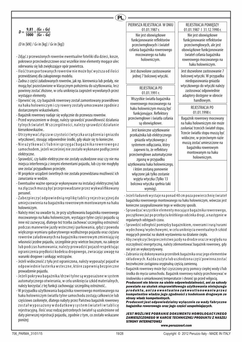
- W przypadku użytkowania bagażnika rowerowego montowanego na haku holowniczym światła tylne samochodu zostają całkowicie lub częściowo zasłonięte, dlatego nabyty przez Państwa bagażnik rowerowy z o s t a ł w y p o s a ż o n y w d o d a t k o w y s y s t e m ś w i a t e ł i w t a b l i c ę rejestracyjną. Ilość oraz rodzaj potrzebnych świateł są uzależnione od daty pierwszej rejestracji pojazdu, zgodnie z tym, co zostało wskazane poniżej:
- Jeżel i ładunek w ystaje na ponad 40 cm poza powier zchnię świateł
bagażnika rowerowego montowanego na haku holowniczym, wówczas jest
konieczne zasygnalizowanie tego w widoczny sposób.
- Sprawdzać wsz ystkie element y mocujące bagażnika rowerowego,
początkowo już po przebyciu krótkiego odcinka drogi, a następnie w
regularnych odstępach czasu.
- Sprawdzić odległość pomiędzy bagażnikiem, rowerami i rurą/rurami
w ydechową/w ydechow ymi, w celu uniknięcia ewentualnych szkód
mogących powstać na skutek wystawienia na działanie ciepła.
- Aby z większ yć bezpieczeńst wo jazdy na drodze oraz ze względu na
oszczędność energetyczną, należy zdemontować bagażnik rowerowy, gdy
nie jest on wykorzystywany.
- Zabrania się dokonywania przeróbek bagażnika oraz jego elementów
s k ł a d o w yc h . K a żd a z u ż y t a l u b u s z ko d zo n a c zę ś ć p o w i n n a zo s t a ć
bezzwłocznie zastąpiona oryginalną częścią zamienną.
- Bagażnik rowerowy może być czyszczony przy pomocy ciepłej wody i/lub
środka do mycia samochodu. Bagażnik rowerowy należy przechowywać w
środowisku o umiarkowanej temperaturze i chronić go przed wilgocią.Producent nie bierze na siebie odpowiedzialności, ani za szkody powstałe na skutek nieprawidłowego użytkowania niniejszego p r o d u k t u , a n i z a e w e n t u a l n e z a k w e s t i o n o w a n i e p r z e z kompetentne władze jego zgodności z kodeksem drogowym ze strony władz kompetentnych.Producent jest odpowiedzialny wyłącznie za wady fabryczne bagażnika rowerowego oraz jego części uzupełniających.
JEST MOŻLIWE POBRANIE DOKUMENTU HOMOLOGACYJNEGO ZAMIESZCZONEGO W KARCIE TECHNICZNEJ PRODUKTU Z NASZEJ STRONY INTERNETOWEJ
www.peruzzosrl.com
D = x9,81 (GA x GK)
1000 (GA + GK)
(D in [kN] / GA in [kg] / GK in [kg])
Nie jest obowiązkowe funkcjonowanie reflektorów przeciwmgłowych i świateł
cofania bagażnika rowerowego mocowanego na haku
holowniczym.
Jest dozwolone zastosowanie jednej 7 bolcowej wtyczki.
PIERWSZA REJESTRACJA W DNIU01.01.1987 r.
Nie jest obowiązkowe funkcjonowanie reflektorów przeciwmgłowych, ale jest
obowiązkowe funkcjonowanie świateł cofania bagażnika
rowerowego mocowanego na haku holowniczym.
Jest dozwolone zastosowanie 7 bolcowej wtyczki. W przypadku
niedopasowania gniazda wtyczkowego do wtyczki należy
zastosować odpowiednie adaptery dostępne w obrocie
handlowym.
REJESTRACJA POMIĘDZY 01.01.1987 I 31.12.1990 r.
Wszystkie światła bagażnika rowerowego mocowanego na haku holowniczym muszą być
funkcjonujące. Reflektory przeciwmgłowe i światła cofania
są obowiązkowe.
Jest konieczne użytkowanie przekaźnika lub elektrycznego
gniazda wtyczkowego z systemem odłączania, który
zapewni to, że reflektory przeciwmgłowe automatycznie
zgasną w przypadku użytkowania haka holowniczego,
i które zostaną ponownie włączone jak tylko zostanie
wyjęta wtyczka (Tylko 13 bolcowa wtyczka spełnia taki
wymóg).
REJESTRACJA PO01.01.1991 r.
REJESTRACJA PO01.01.1998 r.
Bagażnik rowerowy mocowany na haku holowniczym nie może zasłaniać trzecich świateł stopu. Trzecie światła stopu muszą być widoczne, w przeciwnym razie muszą zostać umieszczone na
bagażniku rowerowym montowanym na haku
holowniczym.

706_PARMA_31/01/15 20/28 Copyright © 2012 Peruzzo Italy - MADE IN ITALY
CZNÁVOD NA MONTÁŽ A POUŽÍVÁNÍPři používání tohoto výrobku je nutné mít na paměti níže uvedené informace: nosič jízdních kol je bezpečný výrobek, jestliže je používán správným způsobem. V případě, že je výrobek používán nesprávně, může způsobit škody nejenom vám, ale i ostatním účastníkům silničního provozu, kteří jedou za vámi.
1) Nasaďte uzávěry 1 na čtyřhranné nosné trubky 2 (obr. A).2) Nasaďte uzávěry 3 na nosné rámy 4 (obr. A) a na upínací rám 5
(obr. D2).3) Namontujte podložky 6 na nosný rám 4 , do polohy, která nejvíce
odpovídá rozměrům vašeho kola. Upevněte je pomocí šroubů 7, matic a podložek 8 (obr. A).
4) Připněte hák 9 ke sklápěcímu zařízení 10 (obr. A).5) Namontujte zadní světla 11 na držák světel 12 a upevněte je pomocí
podložek a matic 13 (obr. B). Dejte přitom pozor, abyste nepoškodili kabely. Příliš neutahujte matice, protože by mohlo dojít k poškození plastových částí. Ujistěte se, že jste protáhli 13-pólovou zástrčku otvorem ve středu držáku světel 12.
6) Namontujte rám poznávací značky 14 na držák světel 12 a upevněte ho pomocí šroubů 15 (obr. B).
7) Namontujte takto smontovaný držák světel 12 na čtyřhrannou trubku 16 a připevněte ho pomocí šroubů 17, matic a podložek 18. Dávejte pozor na to, aby se táhlo sklápěcího mechanismu 9 zasunulo do příslušné štěrbiny (obr. C).
8) Montáž upínacího rámu 5:- Na obou stranách odšroubujte a sejměte rukojeti 19 a podložky 20 (obr. D1);- Proveďte kroky 1, 2 (pouze pro čl. 706/4) a 3 (Obr. D2);- Vložte upínací rám 5 do sedla regulačních kol 21 a připevněte ho pomocí podložek 20 a koleček 19 (obr. D2).
Pro bezpečnou instalaci nosiče a zamezení vzniku škod na vozidle doporučujeme využít pomoci další osoby.
9) Zatáhněte za páku 22 směrem nahoru a pro její odblokování otáčejte klíčem 23 proti směru hodinových ručiček (obr. E1).
10) Položte upínací mechanismus 24 na kouli tažného zařízení 25 (obr.E2).11) Upínací zařízení zavřete přesunem páky 22 směrem dolů. je potřebná
minimální zavírací síla rovnající se 45 kg. (obr. E2).
Seřízení zavírací síly rukyPři zakoupení výrobku je nutné vždy provést první seřízení. Následně je nutné, před každým použitím výrobku, zkontrolovat zavírací sílu a v případě potřeby provést potřebné seřízení. Pro zamezení nehod nebo škod na vozidle doporučujeme využít i v tomto případě pomoci další osoby. Po zajištění a zvednutí páky 22 musí druhá osoba nosič přidržet ve vodorovné pozici. Šroub 26 je nutné seřídit dodaným klíčem 27 tak, aby zavírací síla vyvíjená na páku byla zvýšena alespoň na 45 kg. (obr.E2). Ujistěte se, že po zavření upínacího zařízení se nosič .
POUZE PRO ČL. 706/412) Vsuňte háky do pásků 35 na hranách zadních dveří vozidla a poté ve
správném směru vsuňte řemeny do přezek 34 (obr. F).DŮLEŽITÉ UPOZORNĚNÍ: Zkontrolujte správné upevnění pásků tak, že jimi zacloumáte. Kontrolujte správné napnutí před vyjetím a během zastávek.
INSTALACE NOSIČE NA TAŽNÉ ZAŘÍZENÍ
13) Umístěte na nosič nejdříve největší a nejtěžší jízdní kolo, umístěte kola na plastové podložky 6 a opřete kolo o svislý opěrný rám 5. Poté jízdní kolo upevněte k opěrnému rámu 28 pomocí fixačního pásku 5 (obr. H1). Zajistěte kola pomocí fixačních pásků 29 (obr. G).
UMÍSTĚNÍ A UPEVNĚNÍ JÍZDNÍCH KOL NA NOSIČ
NAKLÁPĚNÍ NOSIČE (obr. I/L/M)Pro naklopení nosiče přidržujte jednou rukou nosič a druhou rukou zatáhněte za táhlo sklápěcího mechanismu 9 (obr. I ). Abyste se vyhnuli nehodám a škodám, doporučujeme využít při naklápění nosiče pomoci třetí osoby. Pro zavření nosiče ho zvedejte směrem nahoru, dokud nedojde k celkovému zavření sklápěcího zařízení 10 , které přejde z nakloněné polohy (obr. L) do zavřené polohy (obr. M).
14) Zopakujte postup z bodu 13 i pro druhé, třetí a čtvrté jízdní kolo. Pro připevnění druhého a třetího jízdního kola k upevňovacímu držáku 5 použijte upevňovací ramena 30/31 (Obr. H1), zatímco čtvrté kolo je nutno připevnit ke třetímu upevňovacím ramenem 32 (Obr. H2).DŮLEŽITÉ UPOZORNĚNÍ: Pro bezpečnější přepravu kol je nosič vybavený páskem 33 pro upevnění veškerých jízdních kol k upínacímu rámu 5. Utáhněte pásek a ujistěte se, že je jízdní kolo správně namontováno.
Kromě níže uvedených nařízení vás prosíme, abyste se řídili „Podmínkami, radami a provozními omezeními“, které jsou uvedené v certifikátu o schválení typu (ES schválení typu).
- Hmotnost nosičů "PARMA" a maximální nosnost:* Model 706/4 (20,03 kg.) ---> 4 jízdní kola, max. nosnost 60 kg.* Model 706/3 (17,38 kg.) ---> 3 jízdní kola, max. nosnost 60 kg.* Model 706/3A (15,77 kg.) ---> 3 jízdní kola, max. nosnost 60 kg.* Model 706 (15,58 kg.) ---> 2 jízdní kola, max. nosnost 60 kg.
- Nikdy nepřekračujte schválenou nosnost nainstalovaného tažného zařízení. Celková hmotnost nosiče a břemene nesmí překročit schválenou nosnost. Udržujte povrch koule tažného zařízení v čistém stavu a v případě stop po špíně či oleji je odstraňte.
- Řidič je vždy zodpovědný za přepravovaná břemena, a proto je povinen pravidelně kontrolovat jejich správné upevnění nejenom před vyjetím, ale i během cesty.
- Přečtěte si návod k používání vozidla a zkontrolujte, jestli jsou dodrženy specifikace ohledně maximálního zatížení zadní nápravy.
- Zkontrolujte dodržení hodnoty D (maximální nosnost) tažného zařízení uvedené výrobcem automobilu nebo tažného zařízení; hodnota D vyjádřená pro tažné zařízení se musí rovnat alespoň (760 kg)7,6 KN; u starších tažných zařízení je obvykle uvedeno pouze přípustné zatížení tažného zařízení GA a celkové zatížení tažného vozidla GK (místo hodnoty D).V tomto případě je možné hodnotu D vypočítat pomocí hodnot uvedených v návodu k údržbě vozidla nebo v technické knížce:
- Sejměte z jízdních kol určených k přepravě případně namontované dětské sedačky košíky, pláštěnky či jiné prvky, které by se mohly uvolnit či zvýšit aerodynamický odpor.
- Počet přepravovaných kol nesmí překročit počet uvedený u zakoupeného modelu.
- Žádná část kol (např. řidítka nebo pedály) nesmí zůstat v poloze klasického používání, ale vše musí být složeno, aby se zabránilo nebezpečí.
- Ujistěte se, že je nosič správně nainstalovaný na tažném zařízení a že jsou jízdní kola upevněná v souladu s poskytnutými pokyny.
- Nosič je určený pouze pro přepravu jízdních kol.
POZOR – BEZPEČNOSTNÍ PŘEDPISY
D = x9,81 (GA x GK)1000 (GA + GK)
(D in [kN] / GA in [kg] / GK in [kg])

706_PARMA_31/01/15 21/28 Copyright © 2012 Peruzzo Italy - MADE IN ITALY
CZ- Před uvedením vozidla do provozu zkontrolujte dokonalou funkčnost
zadních světel. Zkontrolujte především funkčnost směrových světel.- Udržujte veškeré spojovací části v čistotě (kolík zařízení atd.) a případě
potřeby zasáhněte za použití vhodných materiálů.- Neoužívejte a/nebo nepřipojujte nosič k autu před provedením
elektrického zapojení.- Zkontrolujte případné poškození elektrických kabelů způsobené
interferencí s dalšími elementy vozidla anebo jejich náhodné přestřižení.- Osvětlovací zařízení nejsou navržena pro ponor do vody.- Významnější zásahy na elektrickém rozvodu nebo přípojkách musí
provést specializovaný pracovník.- Zhotovte kopii poznávací značky a pověste ji na nosič jízdných kol na
tažné zařízení.- Připomínáme, že při použití nosiče jízdných kol na tažné zařízení je zadní
část vozidla odlišná od normálu, a proto je nutné dávat mimořádný pozor při couvání a parkování nejenom kvůli délce vozidla, ale i proto, že váha jízdních kol upevněných na nosiči způsobuje změny chování auta a to především v případě bočního větru, brzdění nebo v zatáčkách; Při jízdě dodržujte rychlostní omezení v souladu se silničními pravidly a dávejte pozor na stav vozovky, abyste se vyhnuli přílišným vibracím a nárazům.
- Jestliže dojde k omezení zadní viditelnosti, vybavte vozidlo vhodnými zpětnými zrcátky pro zajištění bezpečné jízdy.
- Jestliže kapota/dveře disponují automatickým otvíráním, při používání této funkce buďte velmi opatrní, čímž se vyhnete případným škodám.
- V případě použití tažného zařízení jsou zadní světla auta zcela nebo částečně zakryta, a proto je nutné na nosič jízdných kol, který jste si zakoupili, namontovat pomocná světla a poznávací značku. Počet a typ potřebných světel závisí na datu první registrace vozidla:
- Jestliže břemeno přečnívá přes povrch světel nosiče na tažné zařízení o více než 40 cm, je nutné zajistit vizuální signalizaci.
- Zkontrolujte, nejprve po ujetí krátkého úseku a poté v pravidelných intervalech, veškeré upínací prvky nosiče.
- Zkontrolujte vzdálenost mezi nosičem, jízdními koly a výfukem, abyste se vyhnuli případným škodám způsobeným vysokou teplotou.
- Pro zvýšení bezpečnosti silničního provozu a pro úsporu energie nosič odmontujte, jestliže ho nepoužíváte.
- Je zakázáno provádět na nosiči a jeho komponentech jakékoliv úpravy. Při výměně jakékoliv opotřebené či poškozené části používejte výhradně originální náhradní díly.
- Při čištění nosiče používejte vlažnou vodu a/nebo přípravek na čištění aut. Skladujte nosič při mírných teplotách a chraňte ho před vlhkostí.
Výrobce není zodpovědný za škody vzniklé nesprávným používáním tohoto výrobku nebo za přestupky, které vzniknou porušením silničních pravidel.
Výrobce je zodpovědný pouze za výrobní vady nosiče a jeho příslušenství.
HOMOLOGAČNÍ POTVRZENÍ SI MŮŽETE STÁHNOUT NA NAŠICH STRÁNKÁCH
www.peruzzosrl.com
UVNITŘ TECHNICKÉHO LISTU VÝROBKU.
Není povinné, aby byly funkční mlhovky a zpětná světla nosiče jízdných kol na tažné zařízení.
Je povoleno použití 7-pólové zástrčky.
REGISTRACE PŘED 01.01.1987
Není povinné, aby byly funkční mlhovky, ale musí být funkční
zpětná světla nosiče jízdných kol na tažné zařízení.
Je povoleno použití 7-pólové zástrčky.
V případě nekompatibility mezi zásuvkou a zástrčkou použijte
příslušné, běžně dostupné adaptéry.
REGISTRACE V OBDOBÍ OD 01.01.1987 DO 31.12.1990
Musí být funkční všechna světla nosiče jízdných kol na tažné
zařízení. Jsou povinné mlhovky a zpětná světla.
Je nutné použít relé nebo elektrickou zásuvku s
odpojovacím systémem, aby došlo k automatickému vypnutí
mlhovek vozidla v případě použití tažného zařízení a k jejich
opětovnému zapnutí v případě odstranění zástrčky (tento požadavek splňuje pouze
13-pólová zástrčka).
REGISTRACE PO01.01.1991
REGISTRACE PO01.01.1998
Nosič jízdných kol na tažné zařízení nesmí překrývat třetí brzdové světlo. Třetí brzdové světlo musí být viditelné; v opačném případě musí být
nainstalováno i na nosiči kol na tažné zařízení.
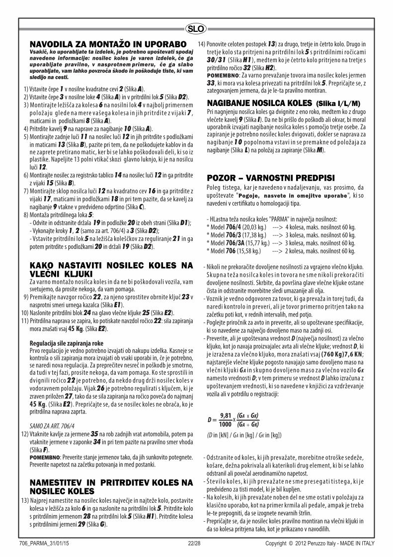
SLO
706_PARMA_31/01/15 22/28 Copyright © 2012 Peruzzo Italy - MADE IN ITALY
NAVODILA ZA MONTAŽO IN UPORABOVsakič, ko uporabljate ta izdelek, je potrebno upoštevati spodaj navedene informacije: nosilec koles je varen izdelek, če ga uporabljate pravilno, v nasprotnem primeru, če ga slabo uporabljate, vam lahko povzroča škodo in poškoduje tiste, ki vam sledijo na cesti.
1) Vstavite čepe 1 v nosilne kvadratne cevi 2 (Slika A).2) Vstavite čepe 3 v nosilne loke 4 (Slika A) in v pritrdilni lok 5 (Slika D2).3) Montirajte ležišča za kolesa 6 na nosilni lok 4 v najbolj primernem
položaju g lede na mere vašega kolesa in j ih pr i t rdite z v i jaki 7 , maticami in podložkami 8 (Slika A).
4) Pritrdite kavelj 9 na naprave za nagibanje 10 (Slika A).5) Montirajte zadnje luči 11 na nosilec luči 12 in jih pritrdite s podložkami
in maticami 13 (Slika B), pazite pri tem, da ne poškodujete kablov in da ne zaprete pretirano matic, ker bi se lahko poškodovali deli, ki so iz plastike. Napeljite 13 polni vtikač skozi glavno luknjo, ki je na nosilcu luči 12.
6) Montirajte nosilec za registrsko tablico 14 na nosilec luči 12 in ga pritrdite z vijaki 15 (Slika B).
7) Montirajte sklop nosilca luči 12 na kvadratno cev 16 in ga pritrdite z vijaki 17, maticami in podložkami 18 in pri tem pazite, da se kavelj za nagibanje 9 vtakne v predvideno odprtino (Slika C).
8) Montaža pritrdilnega loka 5:- Odvite in odstranite držala 19 in podložke 20 iz obeh strani (Slika D1);- Vykonajte kroky 1, 2 (samo za art. 706/4) a 3 (Slika D2);- Vstavite pritrdilni lok 5 na ležišča koleščkov za reguliranje 21 in ga potem pritrdite s podložkami 20 in držali 19 (Slika D2).
Za varno montažo nosilca koles in da ne bi poškodovali vozila, vam svetujemo, da prosite nekoga, da vam pomaga.
9) Premikajte navzgor ročico 22, za njeno sprostitev obrnite ključ 23 v nasprotni smeri urnega kazalca (Slika E1).
10) Naslonite pritrdilni blok 24 na glavo vlečne kljuke 25 (Slika E2).11) Pritrdilna naprava se zapira, ko potiskate navzdol ročico 22: sila zapiranja
mora znašati vsaj 45 Kg. (Slika E2).
Regulacija sile zapiranja rokePrvo regulacijo je vedno potrebno izvajati ob nakupu izdelka. Kasneje se kontrola o sili zapiranja mora izvajati ob vsaki uporabi in, če je potrebno, se naredi nova regulacija. Za preprečitev nesreč in poškodb je smotrno, da tudi v tej fazi, prosite nekoga, da vam pomaga. Ko ste sprostili in dvignili ročico 22 je potrebno, da nekdo drug drži nosilec koles v vodoravnem položaju. Vijak 26 je potrebno regulirati s ključem, ki je zraven priložen 27, tako da se sila zapiranja na ročico poveča do najmanj 45 Kg. (Slika E2). Prepričajte se, da se nosilec koles ne obrača, ko je pritrdilna naprava zaprta.
SAMO ZA ART. 706/412) Vtaknite kavlje za jermene 35 na rob zadnjih vrat avtomobila, potem pa
vtaknite jermene v zaponke 34 in pri tem pazite na pravilno smer vhoda (Slika F).POMEMBNO: Preverite stanje jermenov tako, da jih sunkovito potegnete. Preverite napetost na začetku potovanja in med postanki.
KAKO NASTAVITI NOSILEC KOLES NA VLEČNI KLJUKI
13) Najprej namestite na nosilec koles največje in najteže kolo, postavite kolesa v ležišča za kolo 6 in ga naslonite na pritrdilni lok 5. Pritrdite kolo s pritrdilnim jermenom 28 na pritrdilni lok 5 (Slika H1). Pritrdite kolesa s pritrdilnimi jermeni 29 (Slika G).
NAMESTITEV IN PRITRDITEV KOLES NA NOSILEC KOLES
NAGIBANJE NOSILCA KOLES (Slika I/L/M)Pri nagnjenju nosilca koles ga dvignite z eno roko, medtem ko z drugo vlečete kavelj 9 (Slika I). Da ne bi prišlo do poškodb ali okvar, bi moral uporabnik izvajati nagibanje nosilca koles s pomočjo tretje osebe. Za zapiranje je potrebno nosilec koles dvigovati, dokler se naprava za nagibanje 10 popolnoma vstavi in se premakne od položaja za nagibanje (Slika L) na položaj za zapiranje (Slika M).
14) Ponovite celoten postopek 13) za drugo, tretje in četrto kolo. Drugo in tretje kolo sta pritrjeni na pritrdilni lok 5 s pritrdilnimi ročicami 30/31 (Slika H1), medtem ko je četrto kolo pritrjeno na tretje s pritrdilno ročico 32 (Slika H2).POMEMBNO: Za varno prevažanje tovora ima nosilec koles jermen 33, ki mora vsa kolesa privezati na pritrdilni lok 5. Prepričajte se, z zategovanjem jermena, da je le-ta pravilno montiran.
Poleg tistega, kar je navedeno v nadaljevanju, vas prosimo, da upoštevate "Pogoje, nasvete in omejitve uporabe", ki so navedeni v certifikatu o homologaciji tipa.
- HLastna teža nosilca koles "PARMA" in največja nosilnost:* Model 706/4 (20,03 kg.) ---> 4 kolesa, maks. nosilnost 60 kg.* Model 706/3 (17,38 kg.) ---> 3 kolesa, maks. nosilnost 60 kg.* Model 706/3A (15,77 kg.) ---> 3 kolesa, maks. nosilnost 60 kg.* Model 706 (15,58 kg.) ---> 2 kolesa, maks. nosilnost 60 kg.
- Nikoli ne prekoračite dovoljene nosilnosti za vgrajeno vlečno kljuko. Skupna teža nos i lca koles in tovora ne sme nikol i prekorač i t i dovoljene nosilnosti. Skrbite, da površina glave vlečne kljuke ostane čista in odstranite morebitne sledi umazanije ali olja.
- Voznik je vedno odgovoren za tovor, ki ga prevaža in torej tudi, da naredi kontrolo in preveri, ali je tovor primerno pritrjen tako na začetku poti kot, v rednih intervalih, med potjo.
- Poglejte priročnik za avto in preverite, ali so upoštevane specifikacije, ki so navedene za največjo dovoljeno maso na zadnji osi.
- Preverite, ali je upoštevana vrednost D (največja nosilnost) za vlečno kljuko, kot jo navaja proizvajalec avta ali vlečne kljuke; vrednost D, ki je izražena za vlečno kljuko, mora znašati vsaj (760 Kg)7,6 KN; najstarejše vlečne kljuke pogosto navajajo samo dovoljeno maso na vlečni k l juki G A in skupno dovol jeno maso za vlečno vozi lo G K namesto vrednosti D; v tem primeru se vrednost D lahko izračuna z upoštevanjem vrednosti, ki so navedene v knjižici za vzdrževanje vozila ali v potrdilu o registraciji:
- Odstranite od koles, ki jih prevažate, morebitne otroške sedeže, košare, dežna pokrivala ali katerikoli drug element, ki bi se lahko odstranil ali povečal aerodinamično napetost.
- Š te v i l o ko l e s, k i j i h p re va ž ate n e s m e p re s e g at i t i s te g a , k i j e predvideno za tisti model, ki je bil kupljen.
- Na kolesih, ki jih prevažate noben del ne sme ostati v položaju za klasično uporabo, kot na primer krmila ali pedale, ampak je treba le-te prepogniti, da se izognete nevarnih štrlin.
- Prepričajte se, da je nosilec koles pravilno montiran na vlečni kljuki in da so kolesa pritrjena tako, kot je prikazano v navodilih.
POZOR – VARNOSTNI PREDPISI
D = x9,81 (GA x GK)
1000 (GA + GK)(D in [kN] / GA in [kg] / GK in [kg])
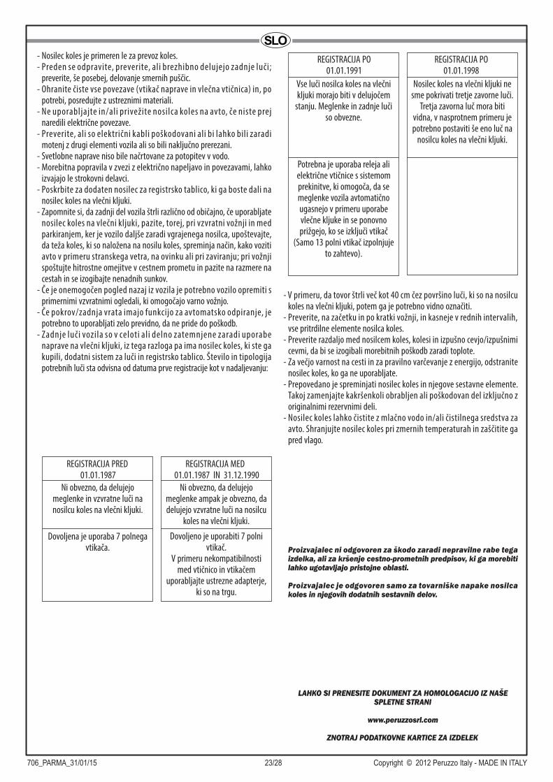
706_PARMA_31/01/15 23/28 Copyright © 2012 Peruzzo Italy - MADE IN ITALY
SLO- Nosilec koles je primeren le za prevoz koles.- Preden se odpravite, preverite, ali brezhibno delujejo zadnje luči;
preverite, še posebej, delovanje smernih puščic.- Ohranite čiste vse povezave (vtikač naprave in vlečna vtičnica) in, po
potrebi, posredujte z ustreznimi materiali.- Ne uporabljajte in/ali privežite nosilca koles na avto, če niste prej
naredili električne povezave.- Preverite, ali so električni kabli poškodovani ali bi lahko bili zaradi
motenj z drugi elementi vozila ali so bili naključno prerezani.- Svetlobne naprave niso bile načrtovane za potopitev v vodo.- Morebitna popravila v zvezi z električno napeljavo in povezavami, lahko
izvajajo le strokovni delavci.- Poskrbite za dodaten nosilec za registrsko tablico, ki ga boste dali na
nosilec koles na vlečni kljuki.- Zapomnite si, da zadnji del vozila štrli različno od običajno, če uporabljate
nosilec koles na vlečni kljuki, pazite, torej, pri vzvratni vožnji in med parkiranjem, ker je vozilo daljše zaradi vgrajenega nosilca, upoštevajte, da teža koles, ki so naložena na nosilu koles, spreminja način, kako voziti avto v primeru stranskega vetra, na ovinku ali pri zaviranju; pri vožnji spoštujte hitrostne omejitve v cestnem prometu in pazite na razmere na cestah in se izogibajte nenadnih sunkov.
- Če je onemogočen pogled nazaj iz vozila je potrebno vozilo opremiti s primernimi vzvratnimi ogledali, ki omogočajo varno vožnjo.
- Če pokrov/zadnja vrata imajo funkcijo za avtomatsko odpiranje, je potrebno to uporabljati zelo previdno, da ne pride do poškodb.
- Zadnje luči vozila so v celoti ali delno zatemnjene zaradi uporabe naprave na vlečni kljuki, iz tega razloga pa ima nosilec koles, ki ste ga kupili, dodatni sistem za luči in registrsko tablico. Število in tipologija potrebnih luči sta odvisna od datuma prve registracije kot v nadaljevanju:
- V primeru, da tovor štrli več kot 40 cm čez površino luči, ki so na nosilcu koles na vlečni kljuki, potem ga je potrebno vidno označiti.
- Preverite, na začetku in po kratki vožnji, in kasneje v rednih intervalih, vse pritrdilne elemente nosilca koles.
- Preverite razdaljo med nosilcem koles, kolesi in izpušno cevjo/izpušnimi cevmi, da bi se izogibali morebitnih poškodb zaradi toplote.
- Za večjo varnost na cesti in za pravilno varčevanje z energijo, odstranite nosilec koles, ko ga ne uporabljate.
- Prepovedano je spreminjati nosilec koles in njegove sestavne elemente. Takoj zamenjajte kakršenkoli obrabljen ali poškodovan del izključno z originalnimi rezervnimi deli.
- Nosilec koles lahko čistite z mlačno vodo in/ali čistilnega sredstva za avto. Shranjujte nosilec koles pri zmernih temperaturah in zaščitite ga pred vlago.
Proizvajalec ni odgovoren za škodo zaradi nepravilne rabe tega izdelka, ali za kršenje cestno-prometnih predpisov, ki ga morebiti lahko ugotavljajo pristojne oblasti.
Proizvajalec je odgovoren samo za tovarniške napake nosilca koles in njegovih dodatnih sestavnih delov.
LAHKO SI PRENESITE DOKUMENT ZA HOMOLOGACIJO IZ NAŠE SPLETNE STRANI
www.peruzzosrl.com
ZNOTRAJ PODATKOVNE KARTICE ZA IZDELEK
Ni obvezno, da delujejo meglenke in vzvratne luči na nosilcu koles na vlečni kljuki.
Dovoljena je uporaba 7 polnega vtikača.
REGISTRACIJA PRED 01.01.1987
Ni obvezno, da delujejo meglenke ampak je obvezno, da delujejo vzvratne luči na nosilcu
koles na vlečni kljuki.
Dovoljeno je uporabiti 7 polni vtikač.
V primeru nekompatibilnosti med vtičnico in vtikačem
uporabljajte ustrezne adapterje, ki so na trgu.
REGISTRACIJA MED 01.01.1987 IN 31.12.1990
Vse luči nosilca koles na vlečni kljuki morajo biti v delujočem
stanju. Meglenke in zadnje luči so obvezne.
Potrebna je uporaba releja ali električne vtičnice s sistemom prekinitve, ki omogoča, da se meglenke vozila avtomatično ugasnejo v primeru uporabe vlečne kljuke in se ponovno prižgejo, ko se izključi vtikač
(Samo 13 polni vtikač izpolnjuje to zahtevo).
REGISTRACIJA PO01.01.1991
REGISTRACIJA PO01.01.1998
Nosilec koles na vlečni kljuki ne sme pokrivati tretje zavorne luči.
Tretja zavorna luč mora biti vidna, v nasprotnem primeru je potrebno postaviti še eno luč na
nosilcu koles na vlečni kljuki.

706_PARMA_31/01/15 24/28 Copyright © 2012 Peruzzo Italy - MADE IN ITALY
PT
INSTRUÇÕES PARA A MONTAGEM E EMPREGOCada vez que se usa este produto è preciso respeitar as informações abaixo escritas. O porta ciclo è un produto seguro se for usado correttamente, pelo contrário se usado mal pode causar danos a voçês ou a outros que vos estejam seguindo na estrada.
1) Pôr as tampas 1 nos tubos quadrados portantes 2 (fig. A).2) Pôr as tampas 3 nos arcos portantes 4 (fig. A) e no arco de fixagem 5
(fig. D2).3) Montar os encaixes roda 6 no arco portante 4 nas posições mais adaptas
às dimensões da vossa bicicleta fixando-os com os parafusos 7 com porquinhas e anilhas 8 (fig. A).
4) Fixar o gancho 9 ao dispositivo de inclinação 10 (fig. A).5) Montar os faróis posteriores 11 na barra portafaróis 12 fixando-as con
as anilhas e porquinhas 13 (fig. B) fazendo atenção a não causar danos aos cavos. Fazer Atenção a não deteriorar os cavos e a não aper tar demais as porquinhas porque se pode causar dano às partes em plastica. Fazer passar a ficha de 13 polos pelo interior do furo central da barra portafaróis 12.
6) Montar o portamatricula 14 na barra portafaróis 12 fixando-a com parafusos 15 (fig. B).
7) Montar o grupo barra portafaróis 12 ao tubo quadrado 16 fixando-o com os parafusos 17 e porquinhas e anilhas 18, fazendo atenção que o gancho de inclinação 9 se infie na frincha predisposta (fig. C).
8) Montagem do arco de fixagem 5:- Desaparafusar e tirar as maoseiras 19 e as anilhas 20 de ambos os lados (fig. D1);- Efetuar as operações 1, 2 (so’ para art.706/4) e 3 (Fig. D2);- Apoiar o arco de fixagem 5 nas rodas de regulação 21, e fixar-lo com as anilhas 20 e as maoseiras 19 (fig. D2).
Per il montaggio in sicurezza del portaciclo e per evitare danni al veicolo si consiglia di richiedere l’aiuto di un’altra persona.
9) Acionar a alavanca 22 para cima, para desblocar-la rotear a chave 23 em sentido antioràrio (fig. E1).
10) Apoiar o bloco de fixagem 24 à esfera do gancho de tração 25 (fig. E2).
11) O dispositivo de fixagem fecha-se abaixando a alavanca 22: A força da fechagem deve ser par ou pelo menos 45 kg. (fig. E2).
Regolação da força de fechagem da mãoE’ sempre necessario fazer a primeira regulação no momento da compra do produto. Em seguida o control da força de fechagem deve ser feito em cada utilizo procedendo novamente com a regulação no caso que seja necessàrio. Ao fim de prevenir accidentes ou danos è oportuno pedir nesta fase, ajuda a outra pessoa. Depois de ter desblocado e levantado a alavanca 22 o porta ciclo deve ser mantido em posição horizontal pela segunda pessoa. O parafuso 26 deve ser regolado com a chave em dotação 27 de maneira que a força de fechagem sobre a alavanca venha aumentada atè um minimo de 45 kg. (fig. E2). Assegurar-se que com o dispositivo de fixagem fechado, o portaciclo não ande à roda.
SO’ PARA ART.706/412) Infiar os ganchos das correias 35 nas beiras da porta do autoveiculo, e
depois infiar as correias nas fivelas 34 fazendo atenção ao justo sentido da entrada (fig. F).IMPORTANTE: Verificar a segurança das correias puxando por elas. Controlar a tenção no inicio da viagem e durante as paragens.
COMO INSTALAR O PORTACICLO NO GANCHO DE TRAÇÃO
13) Colocar no portaciclo em primeiro lugar a bicicleta mais grande e mais pesada, meter as rodas nos alojamentos roda 6 e apoiar-la contra o arco de fixagem 5 fixar a bicicleta com a correia de fixagem 28 ao arco de fixagem 5 (fig. H1) fixar as rodas com as correias de fixagem 29 (fig. G).
POSICIONAMENTO E FIXAGEM DAS BICICLETAS NO PORTACICLO
INCLINAÇÃO DO PORTACICLO (Fig. I/L/M)Para inclinar o portaciclo levantar-lo con uma mão e com a outra puxar o gancho 9 (fig. I). Para evitar de se magoar e de causar danos è melhor pedir ajuda a uma terceira pessoa. Para a fechagem o portaciclo vem levantado atè quando o dispositivo de inclinação 10 se incaixa completamente passando da posição de inclinação (fig. L) à posição de fechagem (fig. M).
14) Repetir as operações 13 ) para a segunda e terceira bicicleta (se prevista). A segunda e a terceira bicicleta são fixadas ao arco de fixagem 5 con os braços de fixagem 30/31 (fig. H1 ) enquanto a quarta vai fixada à terceira con o bracinho de fixagem 32 (fig. H2).IMPORTANTE: Para uma maior seguranca o portabici è fornecido da correia 33 para amarrar todas as bicicletas ao arco de fixagem 5 assegurar-se esticando sufficientemente a correia che esteja montada correttamente.
Alèm de quanto exposto em seguida, pedimos para observar “Condicões, conselhos e limites de uso” como no certificado de prova para a omologação CE do tipo.
- Peso proprio do portabicicletas “PARMA” e portagem màssima:* Model 706/4 (20,03 kg.) ---> 4 bicicletas, portagem max. 60 kg.* Model 706/3 (17,38 kg.) ---> 3 bicicletas, portagem max. 60 kg.* Model 706/3A (15,77 kg.) ---> 3 bicicletas, portagem max. 60 kg.* Model 706 (15,58 kg.) ---> 2 bicicletas, portagem max. 60 kg.
- Nunca ultrapassar a portagem consentida pelo gancho de tração instalado. O peso completo do portabicicletas e da carga nunca devem ultrapassar a portagem consentida. Manter a superficie da esfera do gancho de tração limpa eliminando traças de sujo ou olio.
- O condutor è sempre responsàvel pelo cargo transportado e por isso tambèm de efetuar un control a fim de verificar a adequada fixagem seja no momento da partida, seja durante a viagem a intervalos regulares.
- Consultar o manual do automòvel e verificar as indicações especificas em respeito ha carga maxima consentida no eixo posterior.
- Verificar o respeito do valor D (portàgem màxima) do gancho de tração indicado pelo produtor do automòvel e do gancho de tração; O valor D esprimido para o gancho de tração deveria ser par ou pelo menos (760kg.)7,6 KN; os ganchos de tração mais velhos a maior parte das vezes indicam sòmente o cargo consentido no gancho tração GA e o cargo total consentido pelo veiculo trainante GK invès do valor D; em tal caso o valor D pode ser assim calculado pegando os valores do l ibrete de manutenção da viatura e do l ibrete de matriculação.
ATENÇÃO-NORMAS DE SEGURANCA
D = x9,81 (GA x GK)
1000 (GA + GK)(D in [kN] / GA in [kg] / GK in [kg])
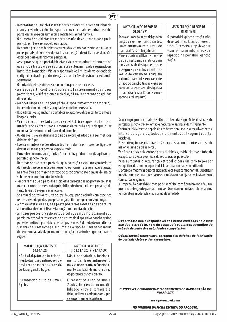
706_PARMA_31/01/15 25/28 Copyright © 2012 Peruzzo Italy - MADE IN ITALY
PT- Desmontar das bicicletas transportadas eventuais cadeirinhas de
crianca, cestinhos, coberturas para a chuva ou qualquer outra coisa che possa destacar-se ou aumentar a resistencia aerodinamica.
- O numero de bicicletas transportadas não deve ultrapassar aquele previsto em base ao modelo comprado.
- Nenhuma parte das bicicletas carregadas, como por esemplo o guiador ou os pedais, devem ser deixados na posição de utilizo classico, vão dobrados para evitar pontas perigosas.
- Assegurar-se que o portabicicletas esteja montado corretamente no gancho de tração e que as bic ic letas estejam fixadas segundo as instruções fornecidas. Viajar respeitando os limites de velocidade do codigo da estrada, pondo atenção às condições da estrada e evitando solavancos.
- O portabicicletas è idoneo sò para o transporte de bicicletas.- A nte s d e p a r t i r co nt ro l a r o co m p l e to f u n c i o n a m e nto d a s l u ze s
posteriores, verificar, em par ticolar, o funcionamento dos piscas direcionais.
- M a nte r l i m p a s a s l i g a çò e s ( fi c h a d i s p o s i t i vo e to m a d a m o t r i z ) , intervindo com materiais apropriados onde fôr necessàrio.
- Não utilizar ou aganchar o portabici ao automòvel sem ter feito antes a ligação eletrica.
- Ve r i fi c a r o b o m e s t a d o d o s c a v o s e l è t t r i c o s , q u e n ã o t e n h a m inter ferencia com outros elementos do veiculo e que de qualquer maneira não sejam cortados accidentalmente.
- Os dispositivos de iluminação não são projetados para ser metidos debaixo de àgua.
- Eventuais intervenções rilevantes no implante el trico e nas ligações devem ser feitos por pessoal especializado.
- Proveder con uma adeguada còpia da chapa do carro, da aplicar no portabici gancho tração.
- Recordar-se que com o portabici gancho tração os volumes posteriores do veiculo são deferentes em respeito ao normal, por isso fazer atenção nas manòvras de marcha atràz e de estacionamento a causa do maior volume em comprimento do veiculo.
- Ter presente que o peso das bicicletas carregadas no portabicicletas muda o comportamento da guidabilidade do veiculo em presença de vento lateral, travagens e em curva.
- Se a visual posterior resulta obstruida, equipar o veiculo com espelhos retrovisores adeguados que possam garantir uma guia em segurança.
- A fi m d e e v i t a r d a n o s, s e a p o r t a p o s te r i o r è d o t a d a d e a b e r t u ra automatica, devem utilizar esta função com muita atenção.
- A s l u z e s p o s t e r i o r e s d o a u t o v e i c o l o v e e m c o m p l e t a m e n t e o u parzialmente cobertas em caso de utilizo do dispositivo gancho traino por este motivo o portabici que compraram està dotado de um ulterior s istema de luzes e chapa. O numero e o t ipo de luzes necessarias dependem da data da prima matriculação do veiculo segundo quanto segue:
- Se o cargo projeta mais de 40 cm. alèm da superficie das luzes do portabici gancho tração, então è necessàrio assinalar-lo visivamente.
- Controlar inicialmente depois de um breve percurso, e successivamente a inter valos regulares, todos o s e lementos de fixagem do por ta- bicicletas.
- Fazer atenção nas marchas atràz e nos estacionamentos a causa do maior volume de transporte .
- Verificar a distancia entre o portabicicletas, as bicicletas e o tubo de escape, para evitar eventuais danos causados pelo calor.
- Para aumentar a segurança estradal e para un correto poupar energetico, desmontar o portabicicletas quando não vem utilizado.
- E’ proibido modificar o portabicicletas e os seus componentes. Substituir imediatamente qualquer parte estragada ou danejada exclusivamente com partes originais.
- A limpeza do portabicicletas pode ser feita com àgua morna e/ou um produto detergente para automovel. Guardare o portabicicletas a uma temperatura moderada e ao abrigo da umidade.
O fabricante não è responsavel dos danos causados pelo mau uso deste produto, nem de eventuais reclames ao codigo da estrada da parte das autoridades competentes.
O fabricante è responsavel somente dos defeitos de fabricação do portabicicletas e dos assessòrios.
E’ POSSIVEL DESCARREGAR O DOCUMENTO DE OMOLOGAÇÃO DO NOSSO SITE:
www.peruzzosrl.com
NO INTERIOR DA FICHA TÈCNICA DO PRODUTO.
Não è obrigatorio o funziona- mento das luzes antinevoeiro e das luzes de marcha atràz do portabici gancho tração.
E’ consentido o uso de uma a 7 polos.
MATRICULAÇÃO ANTES DE01.01.1987
Não è obrigatorio o funziona- mento das luzes antinevoeiro mas è obrigatorio o f unziona- mento das luzes de marcha atràz do portabici gancho tração.
E’ consentido o uso de uma a 7 polos. Em caso de incompati- bilidade entre a tomada e a ficha, utilizar os adaptadores que se encontram em comèrcio.
MATRICULAÇÃO ENTRE O 01.01.1987 E 31.12.1990
Todas as luzes do portabici gancho tração devem ser funcionantes. Luzes antinevoeiro e luzes de marcha atràz são obrigatòrias.
E’ necessàrio o utilizo de um relè ou de uma tomada elètrica com um sistema de desligamento que assegure que as luzes antine - voeiro do veiculo se apaguem automàticamente em caso de utilizo do gancho tração e que se acendam apenas vem desligada a ficha. (Sò a ficha a 13 polos corre- sponde a tal requisito).
MATRICULAÇÃO DEPOIS DE01.01.1991
MATRICULAÇÃO DEPOIS DE01.01.1998
O portabici gancho tração não deve cobrir as luzes do terceiro stop. O terceiro stop deve ser visivel em caso contràrio deve ser repetido no portabici gancho tração.
706_PARMA_31/01/15 26/28 Copyright © 2012 Peruzzo Italy - MADE IN ITALY
NL
INSTRUCTIES VOOR MONTAGE EN GEBRUIKHou rekening met de onderstaande aanbevelingen telkens u dit product gebruikt: de fietsenhouder is een veilig product indien hij correct wordt gebruikt. In geval van een verkeerde gebruikswijze, kan het product schade berokkenen aan uzelf en aan andere weggebruikers die achter u rijden.
1) Plaats de doppen 1 in de vierkante draagbuizen 2 (Fig. A).2) Plaats de doppen 3 in de draagbogen 4 (Fig. A) en in de bevestigin-
gsboog 5 (Fig. D2).3) Monteer de wielsteunen 6 op de draagboog 4 op de positie die het best
g e s c h i k t i s vo o r d e a f m e t i n g e n va n u w fi e t s, m e t b e h u l p va n d e schroeven 7, moeren en ringetjes 8 (Fig. A).
4) Bevestig de haak 9 aan de hoekafstelmechanismen 10 (Fig. A).5) Monteer de achterlichten 11 op de lichtstang 12 met behulp van de
ringetjes en moeren 13 (Fig. B ) maar let op dat de bedrading niet w o r d t b e s c h a d i g d e n d a t d e m o e r e n n i e t o v e r m a t i g w o r d e n aangespannen. De plastic onderdelen kunnen dan immers beschadigd worden. Zorg er voor dat u de 13-polige stekker door de centrale opening van de lichtstang 12 brengt.
6) Monteer de kentekenplaatsteun 14 op de lichtstang 12 met behulp van de schroeven 15 (Fig. B).
7) Monteer de lichtstang 12 aan de vierkante buis 16 met behulp van de schroeven 17, de moeren en ringetjes 18. Let op dat de stelhaak 9 in de daarvoor bestemde opening terecht komt (Fig. C).
8) Montage van de bevestigingsboog 5:-Draai de draaiknoppen 19 en ringetjes 20 van beide zijden los en verwijder ze (Fig. D1);- Voer de handelingen 1, 2 (enkel voor art. 706/4) en 3 uit (Fig. D2);-Plaats de bevestigingsboog 5 in de zitting van de stelwieltjes 21 en bevestig hem vervolgens met de ringetjes 20 en draaiknoppen 19 (Fig. D2).
Om de fietsenhouder op een veilige wijze te monteren en schade tevermijden aan uw voertuig, heeft u de bijstand van een andere persoonnodig.
9) Breng de hendel omhoog 22. De hendel wordt bevrijd door de sleutel 23 in tegenwijzerzin te draaien (Fig. E1).
10) Leg het bevestigingsblok 24 op de bol van de trekhaak 25 (Fig. E2).11) Sluit het bevestigingssysteem door de hendel 22 : naar beneden te
brengen met een minimale kracht van minstens 45 Kg. (Fig. E2).
Afstelling van de handmatige sluitkrachtNa aankoop van het product moet steeds de eerste afstelling worden uitgevoerd. Vervolgens moet de sluitkracht bij elk gebruik opnieuw worden gecontroleerd en indien nodig worden afgesteld. Om ongevallen en schade te vermijden kan u best voor deze interventie bijstand vragen aan een tweede persoon. Breng de hendel 22 omhoog voor bevrijding van het systeem. De fietsenhouder moet nu in de horizontale stand worden gehouden door de tweede persoon. Stel de schroef 26 af met de bijgeleverde sleutel 27 zodat de sluitkracht op de hendel minstens 45 Kg. bedraagt. (Fig. E2). Controleer na sluiting van het bevestigin- gssysteem dat de fietsenhouder niet draait.
ENKEL VOOR ART.706/412) Plaats de haken van de riemen 35 op de randen van de kofferklep van
uw voertuig. Breng dan de riemen door de gespen 34 langs de correcte zijde (Fig. F).BELANGRIJK: : Controleer dat de riemen goed bevestigd zitten door eraan te trekken. Controleer de spanning op de riemen aan het begin van de reis en tijdens de haltes.
HOE DE FIETSENHOUDER MONTEREN OPDE TREKHAAK
SCHUINE STAND VAN DE FIETSENHOUDER (Fig. I/L/M)Om de fietsenhouder schuin af te stellen moet u hem met één hand opheffen en met de andere hand aan de stelhaak 9 trekken (Fig. I). Om letsels en schade te vermijden wordt de bijstand van een tweede persoon vereist tijdens de afstelling van de schuine stand van de fietsenhouder. Ga als volgt te werk voor de sluiting van de fietsen- houder: hef hem zo hoog op dat het hoekafstelmechanisme 10 correct overschakelt van de schuine stand (Fig. L) naar de geblok- keerde stand (Fig. M).
13) Plaats allereerst de grootste en zwaarste fiets op de fietsenhouder: plaats de wielen in de wielsteunen 6 en plaats de fiets tegen de bevestigingsboog 5. Bevestig de fiets met de bevestigingsriem 28 aan de bevestigingsboog 5 (Fig. H1 ). Bevestig de wielen met de bevestigingsriemen 29 (Fig. G).
14) Herhaal de handelingen 13) voor de tweede en derde fiets (indien g e we n s t ) . D e t we e d e e n d e rd e fi e t s wo rd e n b e ve s t i g d a a n d e bevestigingsboog 5 met behulp van de bevestigingsarmen 30/31 (Fig. H1) de vierde fiets wordt bevestigd aan de derde fiets met behulp van de bevestigingsarm 32 (Fig. H2).BELANGRIJK: Voor extra veiligheid wordt bij de fietsenhouder een extra riem 33 bijgeleverd, voor bevestiging van alle fietsen aan de bevestigingsboog 5. Span de riem voldoende aan en controleer dat hij correct werd aangebracht.
PLAATSING EN BEVESTIGING VAN FIETSEN OP DE FIETSENHOUDER
OWij verzoeken u om buiten de onderstaande instructies tevens de "Condities, tips en gebruiksbeperkingen" uit het testcertificaat voor CE-homologatie te respecteren.
- Eigen gewicht van "PARMA" fietsenhouder en maximum draag- kracht:* Model 706/4 (20,03 kg.) ---> 4 fietsen, max. draagkracht 60 kg.* Model 706/3 (17,38 kg.) ---> 3 fietsen, max. draagkracht 60 kg.* Model 706/3A (15,77 kg.) ---> 3 fietsen, max. draagkracht 60 kg.* Model 706 (15,58 kg.) ---> 2 fietsen, max. draagkracht 60 kg.
- De maximum toegelaten draagkracht van de geïnstalleerde trekhaak m a g n o o i t wo rd e n o ve r s c h re d e n . H e t t o t a a l g e w i c h t v a n d e fietsenhouder en diens lading mag nooit hoger zijn dan de maximum toegelaten draagkracht. Hou het opper vlak van de bol van de trekhaak schoon: verwijder vuil en olieresten indien aanwezig.
- De bestuurder is steeds verantwoordelijk voor de getransporteerde l a d i n g e n m o e t d u s o p r e g e l m a t i g e t i j d s t i p p e n d e c o r r e c t e bevestiging controleren, zowel op het vertrek als tijdens de reis.
- De bestuurder is steeds verantwoordelijk voor de getransporteerde l a d i n g e n m o e t d u s o p r e g e l m a t i g e t i j d s t i p p e n d e c o r r e c t e bevestiging controleren, zowel op het vertrek als tijdens de reis.
- R aadpleeg de handleiding van het voer tuig om de maximale belasting op de achteras te kennen.
- Controleer de waarde D (maximale draagkracht) van de trekhaak vermeld door de fabrikant van het voertuig of van de trekhaak; de waarde D van de trekhaak moet groter dan of gelijk zijn aan (760 Kg)7,6 KN; voor oudere trekhaken staat vaak enkel de last vermeld toegelaten voor de haak GA en de totale last toegelaten voor het voertuig GK , en niet de waarde D. In dit geval kan u de waarde D als volgt berekenen uit de waarden vermeld in het onderhoudsboekje van het voertuig of op het inschrijvingsbewijs:
OPGELET - VEILIGHEIDSNORMEN

706_PARMA_31/01/15 27/28 Copyright © 2012 Peruzzo Italy - MADE IN ITALY
NL
- Ver wijder vóór het transport kinderstoeltjes, fietsmandjes, regen- schermen of enige andere accessoires die zouden kunnen loskomen van de fiets of de aerodynamische weerstand zouden kunnen verhogen.
- Het aantal getranspor teerde fietsen mag niet hoger zi jn dan het voorziene aantal dat vermeld wordt voor het aangekochte model.
- Fietsonderdelen, zoals het stuur of de pedalen, mogen niet in de gebruiksstand staan, maar moeten geplooid worden zodat ze niet uitsteken en gevaarlijk zijn.
- Controleer dat de fietsenhouder correct werd gemonteerd op de trek- haak en dat de fietsen werden bevestigd volgens de geleverde instru- cties. Respecteer steeds de snelheidslimieten opgelegd door de weg- code. Let op de condities van het wegdek en vermijd schokken.
- De fietsenhouder is uitsluitend bestemd voor het transport van fietsen.- Controleer alvorens te vertrekken dat de achterlichten perfect werken.
Controleer in het bijzonder de werking van de richtingaanwijzers.- De aansluitingen (stekker voor verlichting en stopcontact op voertuig)
moeten rein blijven. Maak ze schoon met geschikte middelen indien nodig.
- U mag de fietsenhouder niet gebruiken en/of bevestigen aan het voertuig zonder eerst de elektrische aansluitingen te hebben volbracht.
- Controleer dat de elektrische bedrading niet beschadigd is of kan worden door interferentie met andere onderdelen van het voertuig, of op enige wijze per ongeluk kunnen worden doorgesneden.
- Dompel de verlichting niet onder water.- Interventies op het elektrisch systeem en aansluitingen, indien vereist,
mogen uitsluitend uitgevoerd worden door gespecialiseerd personeel.- Maak een kopij van het kenteken en breng dit aan op de fietsenhouder
met trekhaak.- Denk eraan dat bij gebruik van de fietsenhouder met trekhaak de
afmetingen van het voertuig achteraan gewijzigd zijn. Wees dus zeer voorzichtig tijdens het achteruitrijden en parkeren en denk eraan dat het voer tuig langer is, denk eraan dat het gewicht van de fietsen, geladen op de fietsenhouder, het rijgedrag van het voertuig wijzigt bij aanwezigheid van zijwind, tijdens het remmen en in bochten. Respe- cteer steeds de snelheidslimieten opgelegd door de wegcode. Let op de condities van het wegdek en vermijd schokken.
- Indien de zichtbaarheid achteraan belemmerd is, moet u extra achterui- tkijkspiegeltjes aanbrengen op het voertuig voor meer veili-gheid.
- Indien de koffer voorzien is van een automatisch openingsmechanisme, moet u deze functie met de uiterste zorg gebruiken.
- Indien de zichtbaarheid achteraan belemmerd is, moet u extra achterui- tkijkspiegeltjes aanbrengen op het voertuig voor meer veiligheid.
- Wanneer er een aanhangsysteem wordt aangebracht achter het voer- tuig, worden de achterlichten van de auto volledig of gedeeltelijk verduisterd. Daarom werd de fietsenhouder die u heeft aangekocht uitgerust met een extra systeem voor verlichting en aanbrenging van de kentekenplaat. Het aantal en soort lichten is afhankelijk van de datum voor eerste inschrijving van het voertuig:
- Indien de last voor meer dan 40 cm buiten het opper vlak van de verlichting van de fietsenhouder met trekhaak uitsteekt, breng dan een waarschuwingsbord aan.
- Controleer vóór ver trek , na een kor t r i j t ra jec t en ver volgens op r e g e l m a t i g e t i j d s t i p p e n a l l e b e v e s t i g i n g s e l e m e n t e n v a n d e fietsenhouder.
- Let extra op tijdens het achteruitrijden en parkeren. De totale lengte is door de fietsenhouder langer geworden.
- Controleer dat de afstand tussen de fietsenhouder/fietsen en de u i t l a a t / u i t l a t e n v a n h e t v o e r t u i g c o r r e c t i s , o m s c h a d e d o o r oververhitting te vermijden.
- Demonteer de fietsenhouder wanneer hij niet wordt gebruikt. Zo rijdt u veiliger en zuiniger.
- Het is verboden wijzigingen aan te brengen op de fietsenhouder en zijn onderdelen. Beschadigde of versleten onderdelen moeten onmiddellijk worden vervangen door originele vervangstukken.
- M a a k d e fi e t s e n h o u d e r s c h o o n m e t l a u w w a t e r e n / o f e n reinigingsmiddel geschikt voor auto's. Berg de fietsenhouder op op een plek met matige temperatuur en beschermd tegen vochtigheid.
De fabrikant is niet verantwoordelijk voor schade berokkend door een verkeerd gebruikt van dit product, noch voor mogelijke betwisting door de bevoegde autoriteiten ten gevolge van strijdigheid met de verkeersregels.De fabrikant is enkel verantwoordelijk voor fabricagefouten van de fietsenhouder en zijn accessoires.
HET HOMOLOGATIECERTIFICAAT KAN U DOWNLOADEN OP ONZE
www.peruzzosrl.com
IN DE TECHNISCHE KAART VAN HET PRODUCT.
D e w e r k i n g v a n d e m i s t - e n achteruitr i j l ichten i s n iet verplicht op de fietsenhouder met trekhaak.
Het gebruik van een 7-polige stekker is toegelaten.
D = x9,81 (GA x GK)
1000 (GA + GK)(D in [kN] / GA in [kg] / GK in [kg])
INSCHRIJVING VOOR01.01.1987
De werking van de mistlichten is niet verplicht, maar die van de achteruitr i j l ichten van de fietsenhouder met trekhaak is wel verplicht.
Het gebruik van de 7-polige stekker is toegelaten. Wanneer de stekker incompatibel is met het contact, gebruik dan de specifieke adapters verkrijgbaar op de markt.
INSCHRIJVING TUSSEN 01.01.1987 EN 31.12.1990
Alle lichten op de fietsenhouder met trekhaak moeten werkzaam zijn. Mist- en achteruitrijlichten zijn verplicht.
Het is verplicht een relais of elektrisch contact met onder- b r e k i n g s m e c h a n i s m e t e gebruiken dat verzekert dat de mistlichten van het voertuig automatisch worden uitge- schakeld bij gebruik van de trekhaak en terug worden aangeschakeld wanneer de stekker terug wordt uitgetrokken (enkel de 13-polige stekker voldoet hieraan).
INSCHRIJVING NA01.01.1991
INSCHRIJVING NA01.01.1998
De fietsenhouder met trekhaak mag de derde stoplichten van het voertuig niet bedekken. Het derde stoplicht moet zichtbaar zijn. Indien dit niet het geval is, moet het herhaald worden op de fietshouder met trekhaak.

= DISPONIBILEAVAILABLE
AMRAP
CODICE PRODOTTOPRODUCT REFERENCE
DESCRIZIONEDESCRIPTION 706 706/3 706/4 706/3A
965
POGGIARUOTA CON CINGHIA IN PLASTICAWHEEL SUPPORT COMPLETE OF PLASTIC STRAP
397
2 CINGHIE DI SICUREZZA CONFIBBIA2 SAFETY STRAPS WITHBUCKLES
907
2 CINGHIETTE CM 33 CON FIBBIE IN ZAMA DA 202 STRAPS 33 CM WITH ZAMACBUCKLES
400
2 CINGHIE CONGANCIO CM 1002 STRAPS 100CM WITH HOOK
905
6 COPRIGANCIO
6 HOOK COVERS
941
2 SPUGNE APPOGGIO DIAM.30 MM.2 FOAM PROTECTORS 30MM. DIA
946
SET CHIUSURA CON POMELLODIAM.30 MM. QUADRO/TONDO30 MM. DIA SQUARE/ROUNDKNOB ASSEMBLY
948
2 FANALI CON CAVO E SPINA13 POLI2 REAR LIGHTS WITH CABLEAND 13 PIN PLUG
BRACCETTOTERZA-QUARTA BICITHIRD-FOURTH BIKECONNECTION ARM
949
2 PLASTICHE FANALI DX E SX
2 LIGHT BOXES LEFT AND RIGHT
399
PORTATARGA
NUMBERPLATE HOLDER
950
BARRA PORTAFANALI
LIGHT CARRIER BAR
963
COPERTURA IN PLASTICA LEVA
LEVEL PLASTIC COVER
964
COPERCHIO IN PLASTICASISTEMA DI AGGANCIOTOW BALL SYSTEM PLASTICCOVER
693/M
BRACCETTO MEDIO
MEDIUM ARM
693/G
BRACCETTO LUNGO
LONG ARM
693/QT
Spare parts • Ersatzteile • Pièces détachées • Ricambi • Refacciones • Części zamienne • Náhradní díly • Rezervni deli
706_PARMA_31/01/15 28/28 Copyright © 2012 Peruzzo Italy - MADE IN ITALY