Convegno Geotecnico "I cedimenti differenziali dei terreni" - intervento Modoni

IContents
I
© 2020 Geostru
GITPart I GIT 1
Part II NTC2018 1
................................................................................................................................... 21 Programmazione indagini
................................................................................................................................... 22 Volume significativo
................................................................................................................................... 43 Profondità indagine
Part III Eurocodice (EN 1997) 7
................................................................................................................................... 71 EN 1997 - 1
.......................................................................................................................................................... 8Geotechnical design
................................................................................................................................... 82 EN 1997 - 2
.......................................................................................................................................................... 9Content of Eurocode 7-2
......................................................................................................................................................... 9General
......................................................................................................................................... 9Definitions
......................................................................................................................................... 10Objectives
......................................................................................................................................................... 11Planning of ground investigations
......................................................................................................................................... 12Sequence of ground investigations
......................................................................................................................................... 12Design investigations
......................................................................................................................................... 13Annex B.3 Examples
......................................................................................................................................... 19Sampling
......................................................................................................................................................... 20Soil and rock sampling
......................................................................................................................................................... 20Field tests in soil and rock
......................................................................................................................................... 21Cone penetration tests
......................................................................................................................................... 22Annex D
......................................................................................................................................... 22Annex D.1
......................................................................................................................................................... 23Laboratory tests
......................................................................................................................................... 24Strength testing of soil - Annex P
......................................................................................................................................... 25Annex Q
......................................................................................................................................... 25Annex S
......................................................................................................................................................... 26Ground investigation report
......................................................................................................................................... 27Summary
Part IV Bibliografia 28
Part V Geoapp 28
................................................................................................................................... 291 Sezione Geoapp
Part VI Contatti 29
Index 0
GIT1
© 2020 Geostru
1 GIT
Stima volume geotecnico significativo – GIT
GIT è un software che consente di effettuare la stima del volume
geotecnico significativo secondo:
· NTC 2018;
· Lancellotta e Calavera (2006),
· Sollecitazioni indotte;
· Eurocodice 7 (EN1997).
Il volume significativo da indagare è costituito dalla massa di terreno
entro il quale si risentono gli effetti dell’intervento. Tra gli effetti è
possibile considerare:
1. modifiche dello stato tensionale per aumenti di pressione (es.
fondazioni) o scarichi tensionali (scavi);
2. variazioni nel regime delle acque sotterranee per drenaggi o
impermeabilizzazioni indotti dalle opere;
3. inquinamento diretto o indotto dagli interventi;
4. modifiche delle condizioni di stabilità dei versanti per variazioni
planoaltimetriche o modifiche del regime delle acque;
5. modifiche ambientali per apertura di cave di prestito o accumuli
di materiali provenienti da scavi.
2 NTC2018
6.1.2. Prescrizioni generali
Le scelte progettuali devono tenere conto delle prestazioni attese delle
opere, dei caratteri geologici del sito e delle condizioni ambientali. I
risultati dello studio rivolto alla caratterizzazione e modellazione
geologica, di cui al § 6.2.1 devono essere esposti in una specifica
relazione geologica.
Le analisi di progetto devono essere basate su modelli geotecnici
dedotti da specifiche indagini e prove definite dal progettista in base alla
tipologia dell’opera o dell’intervento e alle previste modalità esecutive.
Le scelte progettuali, il programma e i risultati delle indagini, la
caratterizzazione e la modellazione geotecnica di cui al § 6.2.2,
unitamente alle analisi per il dimensionamento geotecnico delle opere e

NTC2018 2
© 2020 Geostru
alla descrizione delle fasi e modalità costruttive, devono essere illustrati
in una specifica relazione geotecnica.
6.2. Articolazione del progetto
Il progetto delle opere e degli interventi si articola nelle seguenti fasi:
1. caratterizzazione e modellazione geologica del sito;
2. scelta del tipo di opera e di intervento e programmazione delle
indagini ;
3. caratterizzazione fisico-meccanica dei materiali presenti nel
volume significativo e definizione dei modelli geotecnici di
sottosuolo (cfr. § 3.2.2);
4. definizione delle fasi e delle modalità costruttive;
5. verifiche della sicurezza e delle prestazioni
6. programmazione delle attività di controllo e monitoraggio
2.1 Programmazione indagini
Programmare le indagini geologiche e geotecniche è un'operazione
complessa ed estremamente delicata. Il programmatore delle indagini
deve avere contezza da subito delle caratteristiche dell'opera di
progetto, anche se in forma preliminare, degli strumenti di indagine da
mettere in campo anche in relazione al tipo di terreno e dei parametri
da ottenere per il problema geotecnico specifico.
Il programmatore delle indagini deve:
o scegliere i mezzi di indagine compatibili con il terreno interessato
e con il tipo di opera;
o decidere l’estensione verticale delle indagini, il numero delle prove
e la loro ubicazione.
2.2 Volume significativo
Cos'è il volume significativo?
2

GIT3
© 2020 Geostru
Per volume significativo di terreno si intende la parte di sottosuolo
influenzata, direttamente o indirettamente, dalla costruzione del
manufatto e che influenza il manufatto stesso.
Fig.1 - Volume significativo. La sua estensione dipende dal tipo e
dimensione dell'opera, dai carichi trasmessi e dalle caratteristiche del
terreno.
Il volume significativo da indagare è costituito dalla massa di terreno
entro il quale si risentono gli effetti dell’intervento. Essi possono essere:
1. modifiche dello stato tensionale per aumenti di pressione (es.
fondazioni) o scarichi tensionali (scavi);
2. variazioni nel regime delle acque sotterranee per drenaggi o
impermeabilizzazioni indotti dalle opere;
3. inquinamento diretto o indotto dagli interventi;
4. modifiche delle condizioni di stabilità dei versanti per variazioni
planoaltimetriche o modifiche del regime delle acque;
5. modifiche ambientali per apertura di cave di prestito o accumuli
di materiali provenienti da scavi.
6.2.2 Indagini, Caratterizzazione e Modellazione Geotecnica
Le indagini geotecniche devono essere programmate in funzione del tipo
di opera e/o di intervento e devono riguardare il volume significativo , e
in presenza di azioni sismiche, devono essere conformi a quanto

NTC2018 4
© 2020 Geostru
prescritto ai §§ 3.2.2 e 7.11.2. Le indagini devono permettere la
definizione dei modelli geotecnici di sottosuolo necessari alla
progettazione. Della definizione del piano delle indagini, della
caratterizzazione e della modellazione geotecnica è responsabile il
progettista.
2.3 Profondità indagine
Il volume significativo si proietta in profondità fino al livello nel quale gli
incrementi di sollecitazioni indotti dai carichi di superficie divengono
trascurabili (0,2 – 0,1 q).
Secondo l’Eurocodice EC7 la profondità di indagine è indicata come
segue (Tab.1):
Fondazione Profondità
Plinti isolati(1÷3)·B
Travi rovesce
Platea
Palo ~L+5·d
Gruppo di pali >L+B'
Rilevati e rinterri
Tab.1 - Profondità delle indagini. Con B è indicata la larghezza
caratteristica della fondazione, con L la lunghezza del palo di diametro d,
con B’ la larghezza minore del rettangolo che circoscrive il gruppo di pali;
con w il generico cedimento e con wf il cedimento finale.
Una rappresentazione indicativa dei volumi interessati da normali opere è
indicata nelle Raccomandazioni sulla programmazione ed esecuzione
delle indagini geotecniche edite dall’Associazione Geotecnica Italiana
(A.G.I., 1977).
In dette raccomandazioni si suggerisce di investigare il terreno con
almeno 3 verticali, 1 verticale ogni 600 mq oltre le prime tre, per normali
edifici e 1 verticale ogni 50-100 m per opere sviluppate in lunghezza
(muri, argini).
Nel caso di studi per fondazioni, di regola si trascurano gli effetti del
terreno situato a profondità maggiore di quella per la quale gli incrementi
di carico sono inferiori a 1/10, 1/15 della pressione litostatica efficace.
Estensione volume da indagare

GIT5
© 2020 Geostru
Fondazioni
In Fig.1 è riportato uno schema dell'estensione del volume da indagare in
riferimento alle fondazioni
Fig.1 - Fondazioni. Da Lancellotta e Calavera, 1999.
Scavi e opere di sostegno (Fig.2)
A B
Fig.2 - A) opere di sostegno; B) scavo o trincea. Da Lancellotta e
Calavera, 1999.
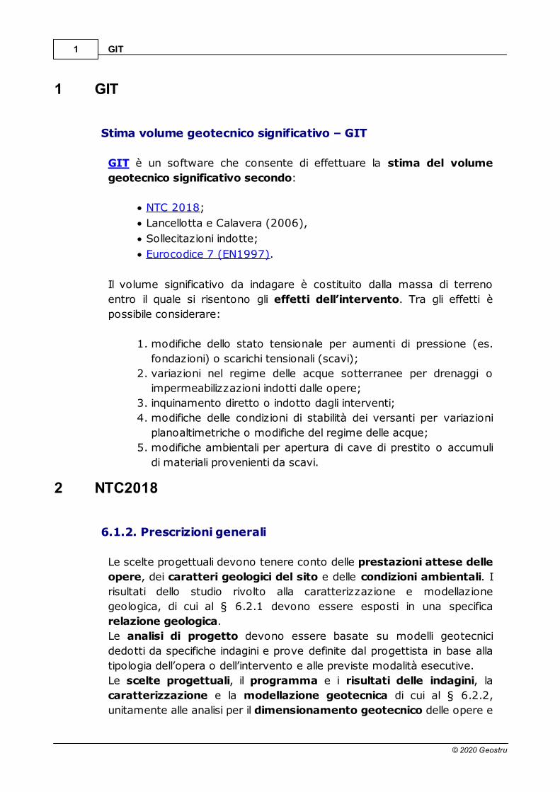
Rilevati e argini (Fig.3)
NTC2018 6
© 2020 Geostru
Fig.3 - Rilevati e argini. Da Lancellotta e Calavera, 1999.
Fondazioni indirette (Fig.4)
Fig.4 - Fondazioni indirette. Da Lancellotta e Calavera, 1999.
Facendo riferimento all’EC7, la distanza tra i punti di indagine e la
profondità della stessa (volume significativo) devono essere definite sulla
base di quanto emerso dall’analisi geologica dell’area, anche in relazione
alle dimensioni del sito e del tipo di opera da realizzare.

GIT7
© 2020 Geostru
3 Eurocodice (EN 1997)
Eurocodice 7 (EN 1997) - Progettazione geotecnica -
L'Eurocodice EN 1997 7 (Eurocodice 7: Progettazione geotecnica)
deve essere applicato agli aspetti geotecnici della progettazione di edifici
e altre opere di ingegneria civile. Ha lo scopo di essere utilizzato con la
EN 1990:2002 che stabilisce i principi e i requisiti di sicurezza e
manutenzione, descrive le basi della progettazione e della verifica e
fornisce linee guida per gli aspetti correlati all'affidabilità strutturale.
L'Eurocodice 7 si compone delle seguenti parti:
1) EN 1997-1:2004, 2013 - Eurocode 7: Geotechnical design -
Part 1: General rules (Norme Generali, dedicata alle regole
generali della progettazione geotecnica, con riferimento sia ad i
terreni che alle rocce.
2) EN 1997-2:2007 - Eurocode 7: Geotechnical design - Part 2:
Ground investigation and testing (Indagini Geotecniche in sito e
in laboratorio, che riguarda l’uso delle indagini in sito e delle prove di
laboratorio nella progettazione geotecnica.)
I valori numerici delle azioni su edifici e altre opere di ingegneria civile da
prendere in considerazione nella progettazione sono forniti nella EN
1991 per i vari tipi di costruzione, mentre le azioni imposte dal suolo,
come le pressioni della terra e dalle acque sotterranee, devono essere
calcolate secondo alle norme della EN 1997.
Standard europei separati saranno usati per trattare le questioni di
esecuzione e lavorazione. Nella norma EN 1997 l'esecuzione è coperta
nella misura necessaria per conformarsi alle ipotesi delle regole di
progettazione. La EN 1997 non copre i requisiti speciali della
progettazione sismica. La EN 1998 fornisce regole aggiuntive per la
progettazione sismica geotecnica, che completano o adattano le regole
della presente norma.
3.1 EN 1997 - 1
EN 1997-1:2004, 2013 - Eurocode 7: Geotechnical design - Part
1: General rules
Parte 1: Norme Generali - dedicata alle regole generali della
progettazione geotecnica

Eurocodice (EN 1997) 8
© 2020 Geostru
L’Introduzione alla (norma) EN 1997-1 (1), Eurocodice 7: Progettazione
Geotecnica, Parte 1: Regole Generali, si compone principalmente di
paragrafi che sono comuni a tutte le parti di tutti gli Eurocodici, ovvero
paragrafi relativi a:
· la preparazione al programma degli Eurocodici;
· il programma stesso degli Eurocodici;
· lo stato e il campo di applicazione degli Eurocodici;
· le normative nazionali che implementano gli Eurocodici;
· i collegamenti tra gli Eurocodici e le specifiche tecniche di
armonizzazione (Norme Europee, EN, e Approvazioni Tecniche
Europee, ETA) per i prodotti.
Tale Introduzione include, inoltre, due brevi paragrafi su:
· le informazioni aggiuntive specifiche dell’Eurocodice 7;
· l’Allegato Nazionale per la EN 1997-1.
3.1.1 Geotechnical design
2.4 Geotechnical design by calculation
2.4.1 General
(2) It should be considered that knowledge of the ground conditions
depends on the extent and quality of the geotechnical investigations.
Such knowledge and the control of workmanship are usually more
significant to fulfilling the fundamental requirements than is precision in
the calculation models and partial factors.
3.2 EN 1997 - 2
EN 1997-2:2007 - Eurocode 7: Geotechnical design - Part 2:
Ground investigation and testing
Parte 2: Indagini Geotecniche in sito e in laboratorio -
riguarda l’uso delle indagini in sito e delle prove di laboratorio nella
progettazione geotecnica.

GIT9
© 2020 Geostru
1.1.2 Scope of Eurocode 7-2
(1)EN 1997-2 is intended to be used in conjunction with EN 1997-1 and
provides rules supplementary to EN 1997-1 related to:
• planning and reporting of ground investigations;
• general requirements for a number of commonly used laboratory
and field tests;
• interpretation and evaluation of test results;
• derivation of values of geotechnical parameters and coefficients.
3.2.1 Content of Eurocode 7-2
1. General
2. Planning of ground investigations
3. Soil and rock sampling and groundwater measurements
4. Field tests in soil and rock
5. Laboratory tests on soil and rock
6. Ground investigation report
23. Annexes
3.2.1.1 General
Part 1: General rules
1.1.2 Scope of Eurocode 7-2
(1)EN 1997-2 is intended to be used in conjunction with EN 1997-1 and
provides rules supplementary to EN 1997-1 related to:
• planning and reporting of ground investigations;
• general requirements for a number of commonly used laboratory
and field tests;
• interpretation and evaluation of test results;
• derivation of values of geotechnical parameters and coefficients.
3.2.1.1.1 Definitions
1.5 Definitions
1.5.3 Specific definitions used in EN 1997 - 2
1.5.3.1 Derived value
Value of a geotechnical parameter obtained from test results by theory,
correlation or empiricism.
9
11
20
20
23
26

Eurocodice (EN 1997) 10
© 2020 Geostru
3.2.1.1.2 Objectives
2.1 Objectives
2.1.1 General
(1) P Geotechnical investigations shall be planned in such a way as
to ensure that relevant geotechnical information and data are
available at the various stages of the project.
(6) Before designing the investigation programme, the available
information and documents should be evaluated in a desk study.
(7) Examples of information and documents that can be used are:
• geological maps and descriptions;
• previous investigations at the site and in the surroundings;
• aerial photos and previous photo interpretations;
• topographical maps;
2.1.2 Ground
(1) P Ground investigations shall provide a description of ground
conditions relevant to the proposed works and establish a basis for
the assessment of the geotechnical parameters relevant for all
construction stages.
(2) The information obtained should enable assessment of the
following aspects, if possible:
· the suitability of the site with respect to the proposed
construction and the level of acceptable risks;
• the deformation of the ground caused by the structure or
resulting from construction works, its spatial distribution and
behaviour over time;
The information obtained should enable assessment of the following
aspects, if possible (continued):
• the safety with respect to limit states (e.g. subsidence, ground heave,
uplift, slippage of soil and rock masses, buckling of piles, etc.);
• the loads transmitted from the ground to the structure (e.g. lateral
pressures on piles) and the extent to which they depend on its design
and construction;
GIT11
© 2020 Geostru
• the foundation methods (e.g. ground improvement, whether it is
possible to excavate, driveability of piles, drainage);
• the sequence of foundation works;
• the effects of the structure and its use on the
surroundings;
(2)The information obtained should enable assessment of the following
aspects, if possible (continued):
• any additional structural measures required (e.g. support of
excavation, anchorage, sleeving of bored piles, removal of
obstructions); the effects of construction work on the
surroundings;
• the type and extent of ground contamination on, and in the vicinity
of, the site;
• the effectiveness of measures taken to contain or
remedy contamination.
2.1.4 Ground water
(2)The information obtained should be sufficient to assess
the following aspects, where relevant:
• the scope for and nature of groundwater-lowering work;
• possible harmful effects of the groundwater on excavations or on
slopes
• any measures necessary to protect the structure;
• the effects of groundwater lowering, desiccation, impounding etc. on
the surroundings;
• the capacity of the ground to absorb water injected during
construction work;
• whether it is possible to use local groundwater, given its chemical
constitution, for construction purposes.
•
3.2.1.2 Planning of ground investigations
2. Planning of ground investigations
2.1 Objectives
2.2 Sequence of ground investigations
2.3 Preliminary investigations
2.4 Design investigations
2.4.1 Field investigations
2.4.2 Laboratory tests
2.5 Controlling and monitoring
10
12
Eurocodice (EN 1997) 12
© 2020 Geostru
3.2.1.2.1 Sequence of ground investigations
2.2 Sequence of ground investigations
Desk studies
Preliminary investigations
Design investigations
Supervision of construction (EC 7-1)
Controlling and monitoring (EC 7-1)
3.2.1.2.2 Design investigations
2.4 Design investigations
2.4.1.3 Locations and depths of the investigation points
(2) When selecting the locations of investigation points, the following
should be observed:
• the investigation points should be arranged in such a pattern that
the stratification can be assessed across the site;
• the investigation points for a building or structure should be
placed at critical points relative to the shape, structural
behaviour and expected load distribution (e.g. at the corners of
the foundation area);
• for linear structures, investigation points should be arranged at
adequate offsets to the centre line, depending on the overall
width of the structure, such as an embankment footprint or a
cutting;
(2) When selecting the locations of investigation points, the following
should be observed (continued):
· for structures on or near slopes and steps in the terrain (including
excavations), investigation points should also be arranged outside
the project area, these being located so that the stability of the
slope or cut can be assessed.
· Where anchorages are installed, due consideration should be
given to the likely stresses in their load transfer zone;
· the investigation points should be arranged so that they do not
present a hazard to the structure, the construction work, or the
surroundings (e.g. they may cause changes to the ground and
groundwater conditions);

GIT13
© 2020 Geostru
(2) When selecting the locations of investigation points, the following
should be observed (continued):
· the area considered in the design investigations should extend
into the neighbouring area to a distance where no harmful
influence on the neighbouring area is expected;
· for groundwater measuring points, the possibility of using the
equipment installed during the ground investigation for continued
monitoring during and after the construction period should be
considered.
(6) P The depth of investigations shall be extended to all strata that will
affect the project or are affected by the construction.
· For dams, weirs and excavations below groundwater level, and
where dewatering work is involved, the depth of investigation
shall also be selected as a function of the hydro-geological
conditions.
· Slopes and steps in the terrain shall be explored to depths below
any potential slip surface.
NOTE: For the spacing of investigation points and investi- gation depths,
the values given in Annex B.3 can be used as guidance.
3.2.1.2.3 Annex B.3 Examples
Annex B.3 Examples of recommendations for the spacing and
depth of investigations
(1) The following spacing of investigation points should be used as
guidance:
• for high-rise and industrial structures, a grid pattern with points at
15 m to 40 m distance;
• for large-area structures, a grid pattern with points at not more
than 60 m distance;
• for linear structures (roads, railways, channels, pipelines, dikes,
tunnels, retaining walls), a spacing of 20 m to 200 m;
• for special structures (e.g. bridges, stacks, machinery
foundations), two to six investigation points per foundation;
Eurocodice (EN 1997) 14
© 2020 Geostru
• for dams and weirs, 25 m to 75 m distance, along vertical
sections.
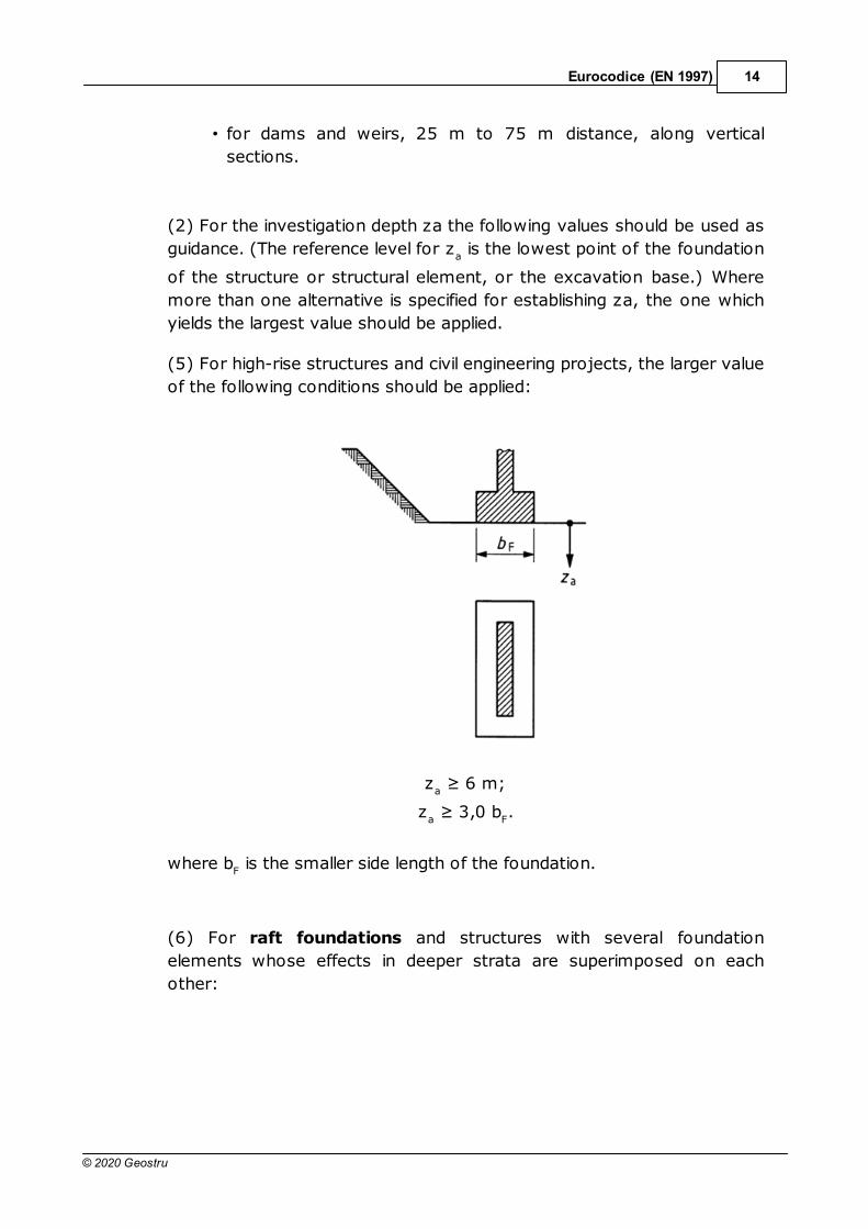
(2) For the investigation depth za the following values should be used as
guidance. (The reference level for za is the lowest point of the foundation
of the structure or structural element, or the excavation base.) Where
more than one alternative is specified for establishing za, the one which
yields the largest value should be applied.
(5) For high-rise structures and civil engineering projects, the larger value
of the following conditions should be applied:
za
za
F.
where bF is the smaller side length of the foundation.
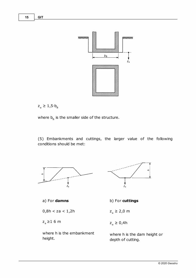
(6) For raft foundations and structures with several foundation
elements whose effects in deeper strata are superimposed on each
other:
GIT15
© 2020 Geostru
za
B
where bB is the smaller side of the structure.
(5) Embankments and cuttings, the larger value of the following
conditions should be met:
a) For damns b) For cuttings
0,8h < za < 1,2h
za
where h is the embankment
height.
za
za
where h is the dam height or
depth of cutting.

Eurocodice (EN 1997) 16
© 2020 Geostru
a) For roads and airfields b) For trenches and pipelines,
the larger value of:
za
formation level.
za
level;
za
A h
where bA h
is the width of
excavation.
(9) For small tunnels and caverns:
bA b
< za < 2,0bAb
GIT17
© 2020 Geostru
where bA b
is the width of excavation.
The groundwater conditions described in (10) b) should also be taken
into account.
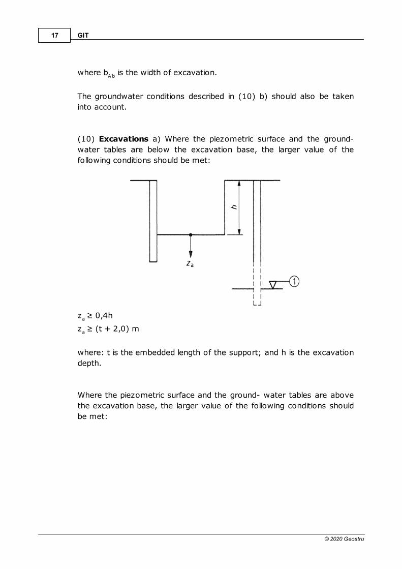
(10) Excavations a) Where the piezometric surface and the ground-
water tables are below the excavation base, the larger value of the
following conditions should be met:
za
za
where: t is the embedded length of the support; and h is the excavation
depth.
Where the piezometric surface and the ground- water tables are above
the excavation base, the larger value of the following conditions should
be met:

Eurocodice (EN 1997) 18
© 2020 Geostru
za
za
where H is the height of the groundwater level above the excavation
base; and t is the embedded length of the support.
(12) For cut-off walls:
za
below the surface of the stratum impermeable to groundwater.
GIT19
© 2020 Geostru
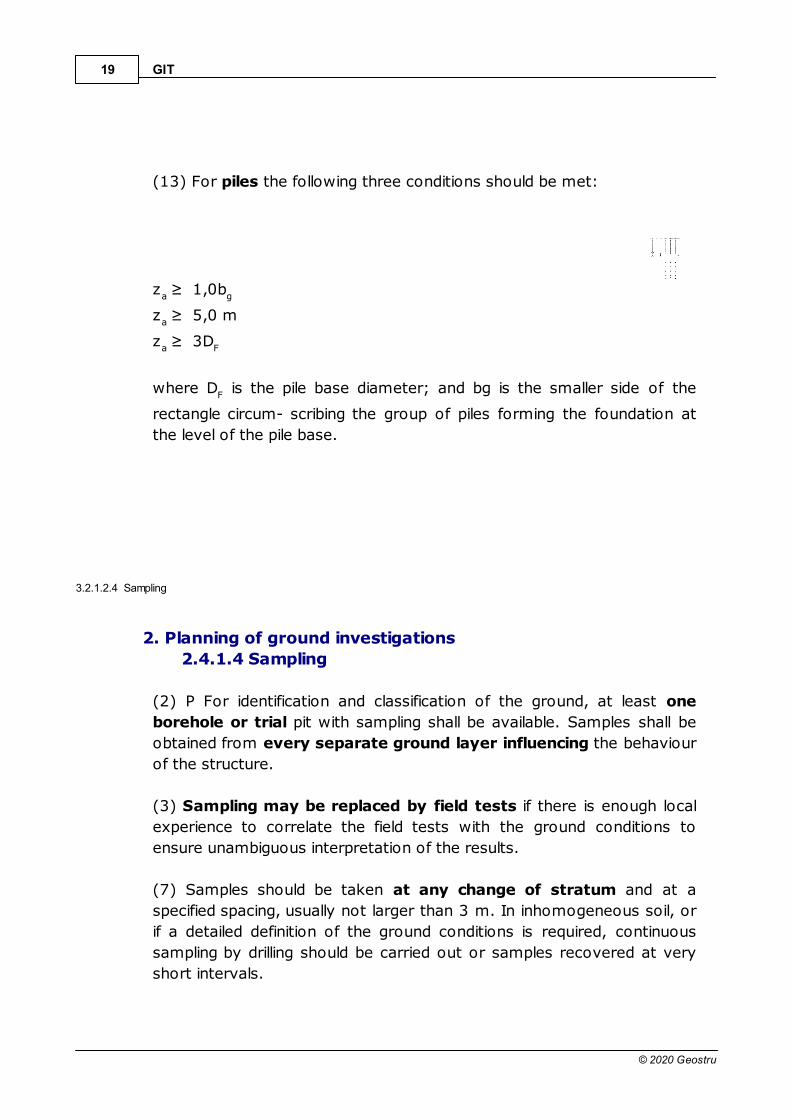
(13) For piles the following three conditions should be met:
za g
za
za F
where DF is the pile base diameter; and bg is the smaller side of the
rectangle circum- scribing the group of piles forming the foundation at
the level of the pile base.
3.2.1.2.4 Sampling
2. Planning of ground investigations
2.4.1.4 Sampling
(2) P For identification and classification of the ground, at least one
borehole or trial pit with sampling shall be available. Samples shall be
obtained from every separate ground layer influencing the behaviour
of the structure.
(3) Sampling may be replaced by field tests if there is enough local
experience to correlate the field tests with the ground conditions to
ensure unambiguous interpretation of the results.
(7) Samples should be taken at any change of stratum and at a
specified spacing, usually not larger than 3 m. In inhomogeneous soil, or
if a detailed definition of the ground conditions is required, continuous
sampling by drilling should be carried out or samples recovered at very
short intervals.
Eurocodice (EN 1997) 20
© 2020 Geostru
2. Planning of ground investigations
2.5 Controlling and monitoring
(1) P A number of checks and additional tests shall be made during the
construction and execution of the project, when relevant, in order to
check that the ground conditions agree with those determined in the
design investigations and that the properties of the delivered
construction materials and the construction works correspond to those
presumed or specified.
(2) P The following control measures shall be applied:
check of ground profile when excavating;
inspection of the bottom of the excavation.
3.2.1.3 Soil and rock sampling
3. Soil and rock sampling and groundwater measurements
3.4 Soil sampling
(1) P Samples shall contain all the mineral constituents of the strata from
which they have been taken. They shall not be contaminated by any
material from other strata or from additives used during the sampling
procedure.
(2) P Three sampling method categories shall be considered (EN ISO
22475-1), depending on the desired sample quality as follows:
• category A sampling methods: samples of quality class 1 to 5
can be obtained;
• category B sampling methods: samples of quality class 3 to 5
can be obtained;
• category C sampling methods: only samples of quality class 5
can be obtained.
(6) P Soil samples for laboratory tests are divided in five quality
classes with respect to the soil properties that are assumed to remain
unchanged during sampling and handling, transport and storage.
3.2.1.4 Field tests in soil and rock
4. Field tests in soil and rock

GIT21
© 2020 Geostru
4.1 General
4.2 General requirements
4.3 Cone penetration tests and piezocone penetration tests
(CPT, CPTU)
4.4 Pressuremeter tests (PMT)
4.5 Flexible dilatometer test (FDT)
4.6 Standard penetration test SPT
4.7 Dynamic probing tests (DP)
4.8 Weight sounding test (WST)
4.9 Field vane test (FVT)
4.10 Flat dilatometer test (DMT)
4.11 Plate loading test (PLT)
3.2.1.4.1 Cone penetration tests
4.3 Cone penetration and piezocone penetration tests (CPT,
CPTU)
(1) The objective of the cone penetration test (CPT) is to determine the
resistance of soil and soft rock to the penetration of a cone and the local
friction on a sleeve.
(2) P The CPT consists of pushing a cone penetrometer vertically into the
soil using a series of push rods. The cone penetrometer shall be pushed
into the soil at a constant rate of penetration. The cone penetrometer
comprises the cone and if appropriate a cylindrical shaft or friction sleeve.
The penetration resistance of the cone qc as well as, if appropriate, the
local friction on the friction sleeve shall be measured.
21

Eurocodice (EN 1997) 22
© 2020 Geostru
Porewater pressure measurement:
u1: on the cone face
u2: at the cylindrical extension of the cone
u3: directly behind the friction sleeve
3.2.1.4.2 Annex D
4.3 Cone penetration tests - Annex D
D.1 Example for deriving values of the effective angle of shearing
resistance and drained Young’s modulus Annex D.1
D.2 Example of a correlation between the cone penetration
resistance and the effective angle of shearing resistance
D.3 Example of a method to determine the settlement for spread
foundations
D.4 Example of a correlation between the oedometer modulus and
the cone penetration resistance
D.5 Examples of establishing the stress-dependent oedometer
modulus from CPT results
D.6 Example of a correlation between compressive resistance of a
single pile and cone penetration resistance
D.7 Example of a method to determine the compressive resistance
of a single pile.
3.2.1.4.3 Annex D.1
Annex D.1
22
GIT23
© 2020 Geostru
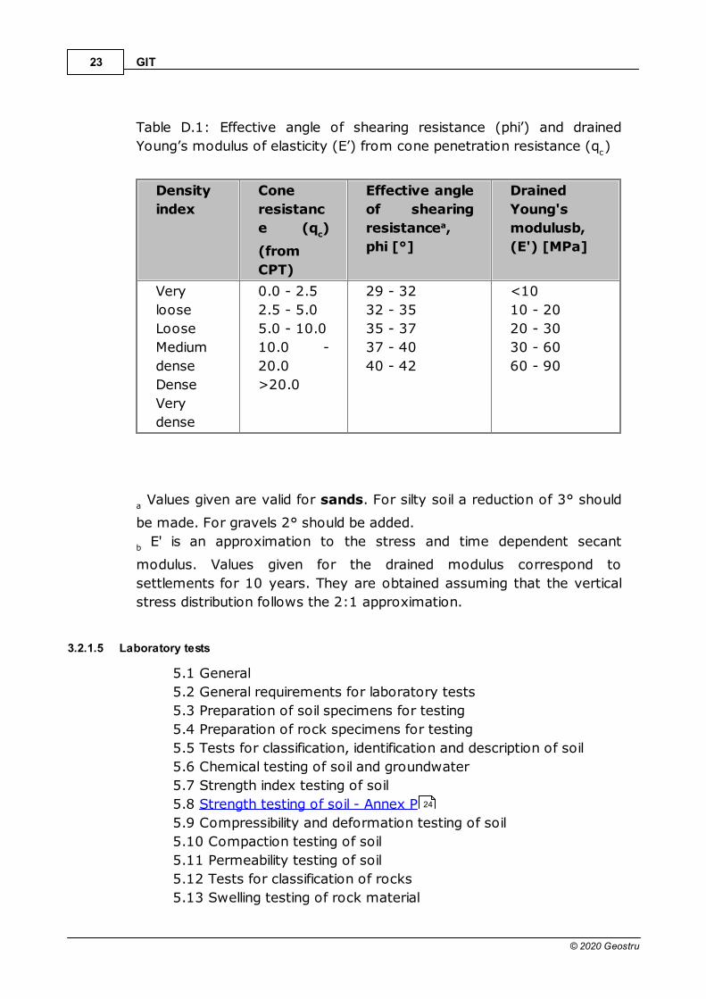
Table D.1: Effective angle of shearing resistance (phi’) and drained
Young’s modulus of elasticity (E’) from cone penetration resistance (qc)
Density
index
Cone
resistanc
e (qc)
(from
CPT)
Effective angle
of shearing
resistancea,
phi [°]
Drained
Young's
modulusb,
(E') [MPa]
Very
loose
Loose
Medium
dense
Dense
Very
dense
0.0 - 2.5
2.5 - 5.0
5.0 - 10.0
10.0 -
20.0
>20.0
29 - 32
32 - 35
35 - 37
37 - 40
40 - 42
<10
10 - 20
20 - 30
30 - 60
60 - 90
a Values given are valid for sands. For silty soil a reduction of 3° should
be made. For gravels 2° should be added.
b E' is an approximation to the stress and time dependent secant
modulus. Values given for the drained modulus correspond to
settlements for 10 years. They are obtained assuming that the vertical
stress distribution follows the 2:1 approximation.
3.2.1.5 Laboratory tests
5.1 General
5.2 General requirements for laboratory tests
5.3 Preparation of soil specimens for testing
5.4 Preparation of rock specimens for testing
5.5 Tests for classification, identification and description of soil
5.6 Chemical testing of soil and groundwater
5.7 Strength index testing of soil
5.8 Strength testing of soil - Annex P
5.9 Compressibility and deformation testing of soil
5.10 Compaction testing of soil
5.11 Permeability testing of soil
5.12 Tests for classification of rocks
5.13 Swelling testing of rock material
24
Eurocodice (EN 1997) 24
© 2020 Geostru
5.14 Strength testing of rock material
3.2.1.5.1 Strength testing of soil - Annex P
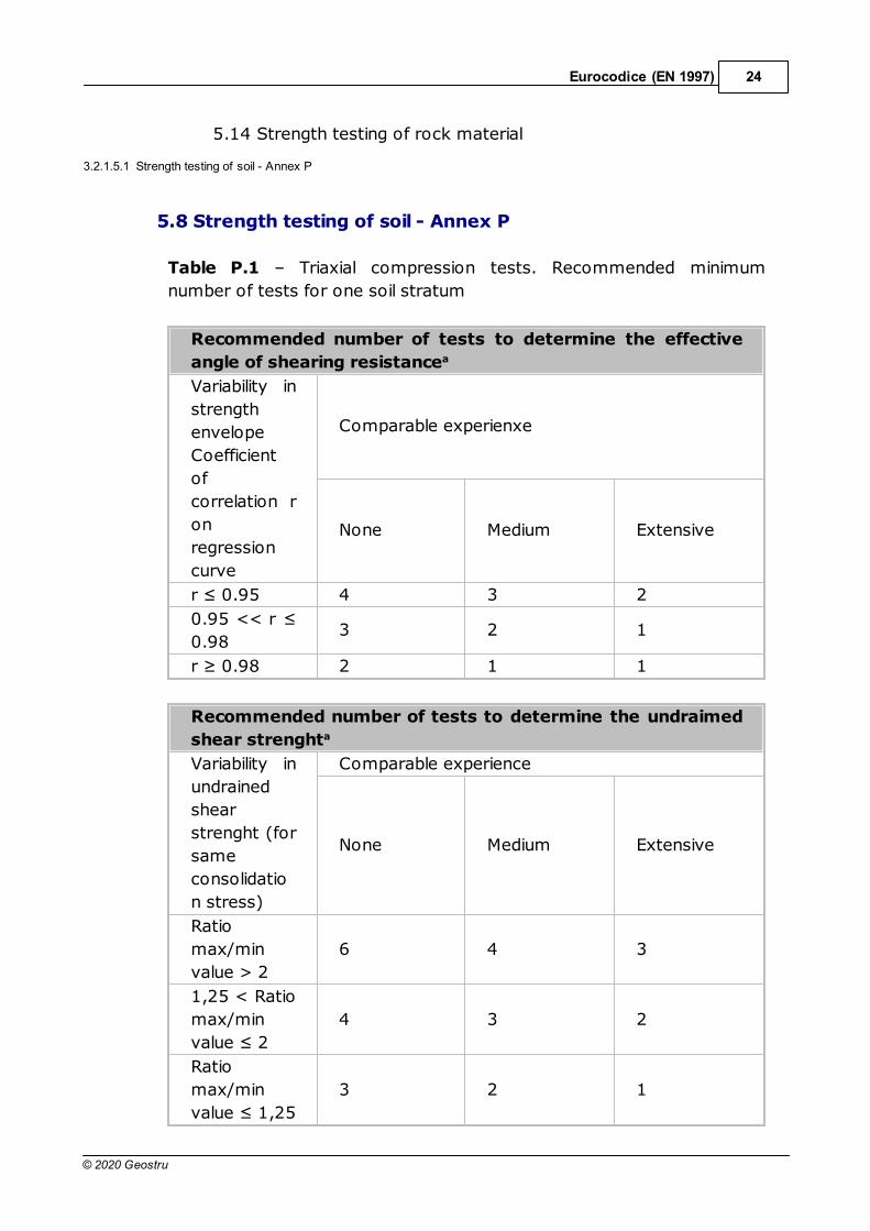
5.8 Strength testing of soil - Annex P
Table P.1 – Triaxial compression tests. Recommended minimum
number of tests for one soil stratum
Recommended number of tests to determine the effective
angle of shearing resistancea
Variability in
strength
envelope
Coefficient
of
correlation r
on
regression
curve
Comparable experienxe
None Medium Extensive
4 3 2
0.983 2 1
2 1 1
Recommended number of tests to determine the undraimed
shear strenghta
Variability in
undrained
shear
strenght (for
same
consolidatio
n stress)
Comparable experience
None Medium Extensive
Ratio
max/min
value > 2
6 4 3
1,25 < Ratio
max/min 4 3 2
Ratio
max/min 3 2 1
GIT25
© 2020 Geostru
Recommended number of tests to determine the undraimed
shear strenghta
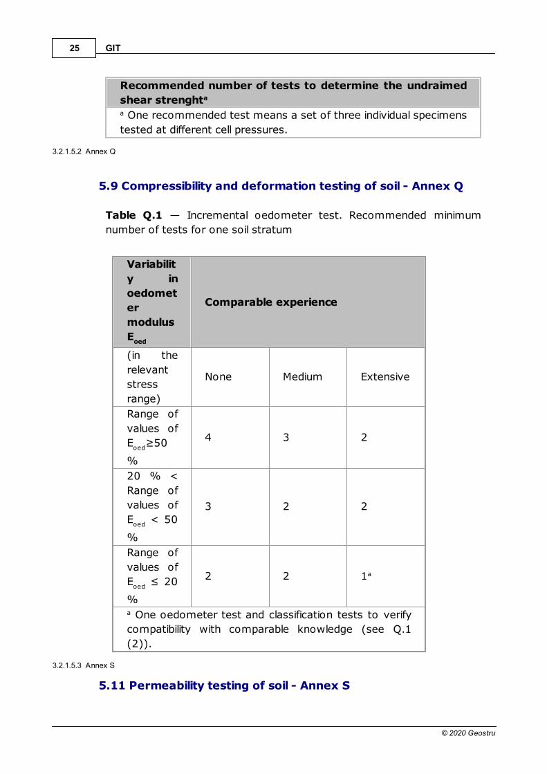
a One recommended test means a set of three individual specimens
tested at different cell pressures.
3.2.1.5.2 Annex Q
5.9 Compressibility and deformation testing of soil - Annex Q
Table Q.1 — Incremental oedometer test. Recommended minimum
number of tests for one soil stratum
Variabilit
y in
oedomet
er
modulus
Eoed
Comparable experience
(in the
relevant
stress
range)
None Medium Extensive
Range of
values of
Eoed
%
4 3 2
20 % <
Range of
values of
Eoed
< 50
%
3 2 2
Range of
values of
Eoed
%
2 2 1a
a One oedometer test and classification tests to verify
compatibility with comparable knowledge (see Q.1
(2)).
3.2.1.5.3 Annex S
5.11 Permeability testing of soil - Annex S

Eurocodice (EN 1997) 26
© 2020 Geostru
Table S.1 - Permeability tests. Recommended minimum number of soil
specimens to be tested for one soil stratum.
Variability
in
measured
coefficient
of
permeabilit
y (k)
Comparable experience
None Medium Extensive
kmax
/kmin
>
1005 4 3
10 <
kmax
/kmin
100
5 3 2
kmax
/kmin
3 2 1a
a A single test and classification tests to verify compatibility with
existing knowledge.
3.2.1.6 Ground investigation report
6. Ground investigation report
6.1 General requirements
6.2 Presentation of geotechnical information
6.3 Evaluation of geotechnical information
6.4 Establishment of derived values
6.1 General requirements
(1) P The results of a geotechnical investigation shall be compiled in the
Ground Investigation Report which shall form a part of the Geotechnical
Design Report.
(1) P The Ground Investigation Report shall consist of, if appropriate:
· a presentation of all available geotechnical information including
geological features and relevant data;
GIT27
© 2020 Geostru
· a geotechnical evaluation of the information, stating the
assumptions made in the interpretation of the test results.
6.2 Presentation of geotechnical information
(1) P The presentation of geotechnical information shall include a factual
account of all field and laboratory investigations.
6.3 Presentation of geotechnical information
(1) P The evaluation of the geotechnical information shall be documented
and include, if appropriate:
· the results and a review of the field investigations,
· laboratory tests and all other information;
· a description of the geometry of the strata;
· detailed descriptions of all strata including their physical properties
and their deformation and strength characteristics;
· comments on irregularities such as cavities.
6.4 Establishment of derived values
(1) P If correlations have been used to derive geotechnical parameters
or coefficients, the correlations and their applicability shall be
documented.
3.2.1.6.1 Summary
Eurocode 7 part 2 Ground investigation and testing:
• gives guidance for the planning of ground investigation with
respect to the location, the depth, the type and the number of
investigations,
• gives the essential requirements for the sampling in soil and rock,
• the handling and processing of the samples in the laboratory and
• defines what a Ground Investigation Report must contain.

Bibliografia 28
© 2020 Geostru
4 Bibliografia
Associazione Geotecnica Italiana (A.G.I.), 1977. Raccomandazioni sulla
programmazione ed esecuzione delle indagini geotecniche.
Lancellotta R. e Calavera J.. (2006). Fondazioni, chiaramente quanto
segue: McGraw Hill.
NTC2018. Ministero delle infrastrutture e dei trasporti. Decreto 17
gennaio 2018. Aggiornamento delle «Norme tecniche per le
costruzioni».
Schuppener B., 2008 - Eurocode7-Geotechnical design - Part 2 Ground
investigation and testing. Federal Waterways Engineering and
Research Institute, Karlsruhe, Germany. Dissemination of
information workshop, Brussels.
UNI EN 1997-1:2013. Eurocodice 7 - Progettazione geotecnica - Parte
1: Regole generali.
UNI EN 1997-2:2007. Eurocodice 7 - Progettazione geotecnica - Parte
2: Indagini e prove nel sottosuolo.
5 Geoapp
Geoapp: la più grande suite del web per calcoli online
Gli applicativi presenti in Geostru Geoapp sono stati realizzati a supporto
del professionista per la soluzione di molteplici casi professionali.
Geoapp comprende oltre 40 applicazioni per: Ingegneria, Geologia,
Geofisica, Idrologia e Idraulica.
La maggior parte delle applicazioni sono gratuite, altre necessitato di
una sottoscrizione (subscription) mensile o annuale.
Perchè si consiglia la subscription?
Perchè una subscription consente di:
· usare applicazioni professionali ovunque e su qualunque
dispositivo;
· salvare i file in cloud e sul proprio PC;
· riaprire i file per elaborazioni successive;
· servizi di stampa delle relazioni ed elaborati grafici;
· notifica sull’uscita di nuove applicazioni ed inclusione automatica
nel proprio abbonamento;
GIT29
© 2020 Geostru
· disponibilità di versioni sempre aggiornate;
· servizio di assistenza tramite Ticket.
5.1 Sezione Geoapp
Generale ed Ingegneria, Geotecnica e Geologia
Tra le applicazioni presenti, una vasta gamma può essere utilizzata per
GIT. A tale scopo si consigliano i seguenti applicativi:
Ø Classificazione suoli NTC 2018
Ø Converter
Ø Geostru MAPS
6 Contatti
Entra nell’area Contattaci, per le tue richieste di supporto e ottenere
maggiori informazioni sui nostri servizi.
T
e
l
e
f
o
n
o
:
0690289085
W
h
a
t
s
a
p
p
:
0040 737 28 38 54
E
m
a
il
:

Contatti 30
© 2020 Geostru
O
r
a
r
i
:
Lunedi – Venerdi Ore 9-17
S
u
p
p
o
r
t
o
:
Assistenza: Per il servizio di assistenza usare
preferibilmente l’area dedicata di supporto (Ticket). Da
inizio 2016 l’assistenza per i clienti ITALIANI è affidata
alla SOEG & C. Per informazioni si prega di visitare il
sito www.soeg.it.


![[Geotecnica] Fondazioni - Lancellotta Calavera - Mcgraw Hill](https://static.fdocumenti.com/doc/165x107/54965157ac79594f748b4594/geotecnica-fondazioni-lancellotta-calavera-mcgraw-hill.jpg)