Estado de las informaciones · Versione delle informazioni€¦ · 1 cuadernillo “Garantía y...
46
Kompernaß GmbH Burgstraße 21 44867 Bochum (Germany) Estado de las informaciones · Versione delle informazioni Last Information Update · Stand der Informationen: 03 / 2008 · Ident.-No.: PTBM500032008 - 5 E-3470_Table_Drill_PTBM500_Cover_LB5.indd 1 17.03.2008 16:22:40 Uhr
Transcript of Estado de las informaciones · Versione delle informazioni€¦ · 1 cuadernillo “Garantía y...

Kompernaß GmbH
Burgstraße 21
44867 Bochum (Germany)
Estado de las informaciones · Versione delle informazioni
Last Information Update · Stand der Informationen:
03 / 2008 · Ident.-No.: PTBM500032008 - 5
E-3470_Table_Drill_PTBM500_Cover_LB5.indd 1 17.03.2008 16:22:40 Uhr

Taladro de mesaTrapano da banco
PTBM 500
Tischbohrmaschine Bedienungs- und Sicherheitshinweise
bench drill Operation and Safety Notes
Taladro de mesaInstrucciones de utilización y de seguridad
Trapano da bancoIndicazioni per l’uso e per la sicurezza
E-3470_Table_Drill_PTBM500_Cover_LB5.indd 2 17.03.2008 16:22:41 Uhr

ES Instrucciones de utilización y de seguridad Página 5IT / MT Indicazioni per l’uso e per la sicurezza Pagina 15GB / MT Operation and Safety Notes Page 25DE / AT Bedienungs- und Sicherheitshinweise Seite 35
Klappen Sie vor dem Lesen die Seite mit den Abbildungen aus und machen Sie sich anschließend mit allen Funktionen des Gerätes vertraut.
Before you begin reading this information, please unfold the page with the illustrations and familiarize yourself with all functions of the tool.
Prima di leggere aprire la pagina con le immagini e prendere confidenza con le diverse funzioni dell’apparecchio.
Antes de empezar a leer abra la página que contiene las imágenes y, en seguida, familiarícese con todas las funciones del dispositivo.
E-3470_Table_Drill_PTBM500_Cover_LB5.indd 3 17.03.2008 16:22:41 Uhr

1 2 3 4 5 6 7 8 11 12
13
15
16
18 17192023 2224
31
10
a
25
1028 28
b
c d
29
2627
3230
9
21
14
21
E-3470_Table_Drill_PTBM500_Cover_LB5.indd 4 17.03.2008 16:22:47 Uhr

E-3470_Table_Drill_PTBM500_Cover_LB5.indd 5 17.03.2008 16:22:47 Uhr

E-3470_Table_Drill_PTBM500_Cover_LB5.indd 6 17.03.2008 16:22:47 Uhr

5 ES
Índice
Introducción Uso adecuado ..............................................................................................................Página 6 Componentes ................................................................................................................Página 6 Contenido ......................................................................................................................Página 7 Datos técnicos ...............................................................................................................Página 7
Indicaciones de seguridad Trabajo seguro ..............................................................................................................Página 8Indicaciones de seguridad específicas para taladros de mesa ...............................Página 9
Manejo Montaje .........................................................................................................................Página 10Colocar el taladro de mesa .........................................................................................Página 11 Instalación y puesta en marcha ..................................................................................Página 11 Comprobar la correa trapezoidal ..............................................................................Página 11 Tensar la correa trapezoidal .......................................................................................Página 11 Ajustar el número de revoluciones ..............................................................................Página 11 Regular la mesa de taladrado.....................................................................................Página 12 Seleccionar profundidad de la broca ........................................................................Página 12 Cambiar / tensar la herramienta .................................................................................Página 12 Tensar la pieza de trabajo en el tornillo de banco ...................................................Página 12 Conectar y desconectar el taladro de mesa ..............................................................Página 12 Taladrar .........................................................................................................................Página 12 Trabajar materiales / Ejemplo ......................................................................................Página 13
Mantenimiento y limpieza .........................................................................Página 13
Eliminación ..............................................................................................................Página 13
Informaciones Asistencia ......................................................................................................................Página 13 Declaración de conformidad /Fabricante ..................................................................Página 14
E-3470_Table_Drill_PTBM500_Content_LB5.indd 5 17.03.2008 16:22:58 Uhr
6 ES
Introducción
Taladro de mesa PTBM 500
Q Introducción
Familiarícese con el funcionamiento del dispositivo antes de ponerlo en marcha e infórmese sobre cómo trabajar adecua-
damente con herramientas eléctricas. Para ello, lea las siguientes instrucciones de uso. Guarde estas instrucciones en un lugar seguro. En caso de trans-ferir el aparato a terceros entrégueles también toda la documentación.
Q Uso adecuado
Este aparato está diseñado para taladrar metal, madera, plástico y baldosas utilizando para ello brocas de vástago cilíndrico de 1,5 mm hasta 16 mm de diámetro como máximo. Cualquier otro uso o modificación del aparato se considera in-adecuado y conlleva considerables peligros de accidente. No asumiremos la responsabilidad por los daños ocasionados debido a un uso distinto
del adecuado. El aparato está· destinado solamente para fines particulares.
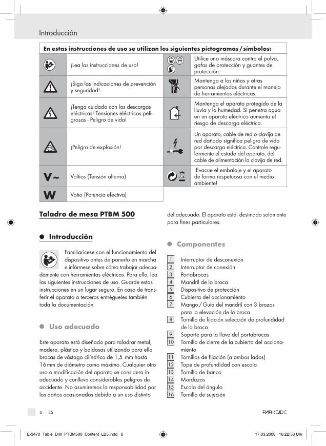
Q Componentes
1 Interruptor de desconexión2 Interruptor de conexión3 Portabrocas4 Mandril de la broca5 Dispositivo de protección6 Cubierta del accionamiento7 Mango / Guía del mandril con 3 brazos
para la elevación de la broca8 Tornillo de fijación selección de profundidad
de la broca9 Soporte para la llave del portabrocas
10 Tornillo de cierre de la cubierta del acciona-miento
11 Tornillos de fijación (a ambos lados)12 Tope de profundidad con escala13 Tornillo de banco14 Mordazas15 Escala del ángulo16 Tornillo de sujeción
En estas instrucciones de uso se utilizan los siguientes pictogramas / símbolos:
¡Lea las instrucciones de uso!Utilice una máscara contra el polvo, gafas de protección y guantes de protección.
¡Siga las indicaciones de prevención y seguridad!
Mantenga a los niños y otras personas alejados durante el manejo de herramientas eléctricas.
¡Tenga cuidado con las descargas eléctricas! Tensiones eléctricas peli-grosas - Peligro de vida!
Mantenga el aparato protegido de la lluvia y la humedad. Si penetra agua en un aparato eléctrico aumenta el riesgo de descarga eléctrica.
¡Peligro de explosión!
Un aparato, cable de red o clavija de red dañado significa peligro de vida por descarga eléctrica. Controle regu-larmente el estado del aparato, del cable de alimentación la clavija de red.
V~ Voltios (Tensión alterna)¡Evacue el embalaje y el aparato de forma respetuosa con el medio ambiente!
W Vatio (Potencia efectiva)
E-3470_Table_Drill_PTBM500_Content_LB5.indd 6 17.03.2008 16:22:58 Uhr

7 ES
Introducción
17 3 tornillos de montaje17 a 3 arandelas17 b 3 arandelas de retención18 Placa base19 Mesa de taladrado20 2 tornillos para el tornillo de banco20 a 4 arandelas20 b 2 tuercas21 Manilla22 Tornillo (inclinación mesa de taladrado)23 Tubo de soporte24 Unidad del motor25 Polea de transmisión del lado del motor26 Polea central de transmisión27 Polea de transmisión del lado del husillo28 Correa trapezoidal29 Conmutador de bloqueo30 1 llave Allen 31 2 tornillos hexagonales interiores32 Llave del portabrocas
Q Contenido
Tras desempaquetar el dispositivo, compruebe inmediatamente el contenido:
1 placa base1 tubo de soporte3 tornillos de montaje / 3 arandelas / 3 arandelas
de retención1 mesa de taladrado con tornillo de sujeción1 tornillo de banco2 tornillos para el tornillo de banco / 4 arandelas /
2 tuercas1 unidad de motor / de transmisión3 brazos par elevación de la broca1 portabrocas1 dispositivo de protección1 llave Allen1 llave para portabrocas1 manual de instrucciones1 cuadernillo “Garantía y asistencia”
Q Datos técnicos
Suministro eléctrico: 230 V ~ 50 HzAbsorción nominal: 500 WN.º de revoluciones del motor: n0 = 1440 r.p.mPortabrocas: 1,5 - 16 mm
de diámetroElevación del husillo: 50 mmMesa de taladrado: 170 x 170 mm /
45° - 0° - 45°N.º de revoluciones del husillo: n0 390 - 2600 r.p.mMasa incl. piezas extraíbles: 27 kg
Información sobre ruido y vibraciones:Nivel de ruido establecido a partir de valoración A.Nivel de presión acústica: 72 dB (A)Nivel de ruido: 85 dB (A)Tolerancia K=3 dB. El nivel de ruido al trabajar puede superar los 88 dB (A).
¡Es necesario llevar protección auditiva!
PTBM 500 KH3133Date of manufacture: 03-2008230 V ~ 50 Hz · 500 W · n0 1440 / min
Kompernaß GmbH 44867 Bochum Germany� www.kompernass.com
max. 50 mm
ø max. 16 mm
ID :00 0 0 0 21765
E-3470_Table_Drill_PTBM500_Content_LB5.indd 7 17.03.2008 16:22:58 Uhr
8 ES
Indicaciones de seguridad
Indicaciones de seguridad
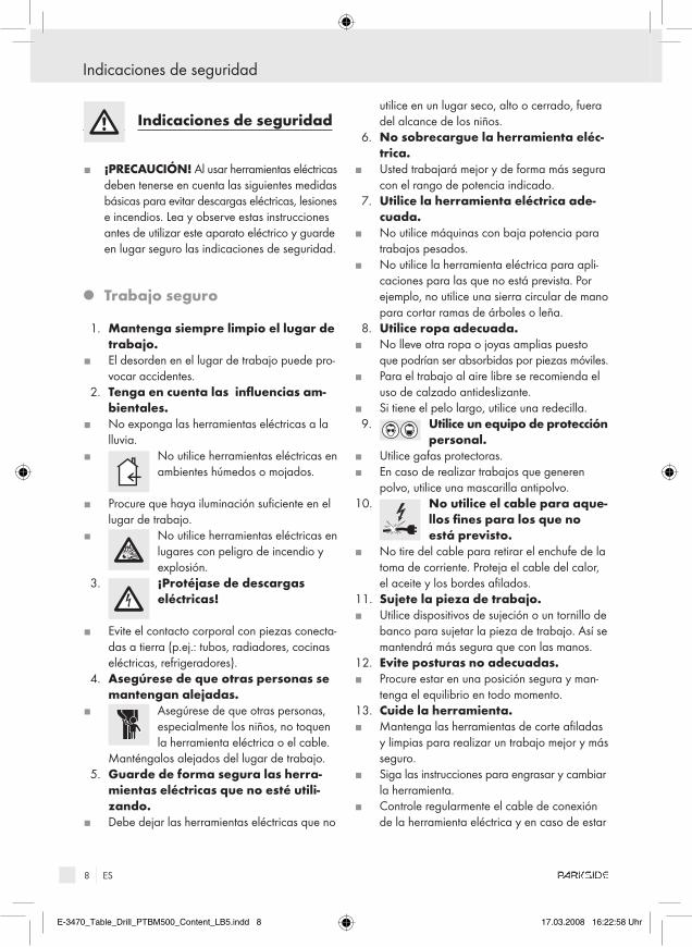
J ¡PrECaUCIÓn! Al usar herramientas eléctricas deben tenerse en cuenta las siguientes medidas básicas para evitar descargas eléctricas, lesiones e incendios. Lea y observe estas instrucciones antes de utilizar este aparato eléctrico y guarde en lugar seguro las indicaciones de seguridad.
Q Trabajo seguro
1. Mantenga siempre limpio el lugar de trabajo.
J El desorden en el lugar de trabajo puede pro-vocar accidentes.
2. Tenga en cuenta las influencias am-bientales.
J No exponga las herramientas eléctricas a la lluvia.
J No utilice herramientas eléctricas en ambientes húmedos o mojados.
J Procure que haya iluminación suficiente en el lugar de trabajo.
J No utilice herramientas eléctricas en lugares con peligro de incendio y explosión.
3. ¡Protéjase de descargas eléctricas!
J Evite el contacto corporal con piezas conecta-das a tierra (p.ej.: tubos, radiadores, cocinas eléctricas, refrigeradores).
4. asegúrese de que otras personas se mantengan alejadas.
J Asegúrese de que otras personas, especialmente los niños, no toquen la herramienta eléctrica o el cable.
Manténgalos alejados del lugar de trabajo. 5. Guarde de forma segura las herra-
mientas eléctricas que no esté utili-zando.
J Debe dejar las herramientas eléctricas que no
utilice en un lugar seco, alto o cerrado, fuera del alcance de los niños.
6. no sobrecargue la herramienta eléc-trica.
J Usted trabajará mejor y de forma más segura con el rango de potencia indicado.
7. Utilice la herramienta eléctrica ade-cuada.
J No utilice máquinas con baja potencia para trabajos pesados.
J No utilice la herramienta eléctrica para apli-caciones para las que no está prevista. Por ejemplo, no utilice una sierra circular de mano para cortar ramas de árboles o leña.
8. Utilice ropa adecuada.J No lleve otra ropa o joyas amplias puesto
que podrían ser absorbidas por piezas móviles.J Para el trabajo al aire libre se recomienda el
uso de calzado antideslizante.J Si tiene el pelo largo, utilice una redecilla. 9. Utilice un equipo de protección
personal.J Utilice gafas protectoras.J En caso de realizar trabajos que generen
polvo, utilice una mascarilla antipolvo.10. no utilice el cable para aque-
llos fines para los que no está previsto.
J No tire del cable para retirar el enchufe de la toma de corriente. Proteja el cable del calor, el aceite y los bordes afilados.
11. Sujete la pieza de trabajo.J Utilice dispositivos de sujeción o un tornillo de
banco para sujetar la pieza de trabajo. Así se mantendrá más segura que con las manos.
12. Evite posturas no adecuadas.J Procure estar en una posición segura y man-
tenga el equilibrio en todo momento.13. Cuide la herramienta.J Mantenga las herramientas de corte afiladas
y limpias para realizar un trabajo mejor y más seguro.
J Siga las instrucciones para engrasar y cambiar la herramienta.
J Controle regularmente el cable de conexión de la herramienta eléctrica y en caso de estar
E-3470_Table_Drill_PTBM500_Content_LB5.indd 8 17.03.2008 16:22:58 Uhr

9 ES
Indicaciones de seguridad
dañado debe dejar que un técnico especiali-zado lo sustituya.
J Compruebe regularmente los cables de pro-longación y reemplácelos si presentan daños.
J Mantenga el mango seco, limpio y sin aceite ni grasa.
14. Desenchufe el aparato de la toma de corriente:
J Cuando no se utilice la herramienta eléctrica, antes de los trabajos de mantenimiento y al cambiar la herramienta, p. ej. hoja de sierra, broca, fresa.
15. no introduzca llaves.J Antes de conectar deben retirarse todas las
llaves y herramientas de ajuste.16. Evite que la herramienta se ponga
accidentalmente en funcionamiento.J Asegúrese de que el interruptor está apagado
al conectar el enchufe en la toma de corriente.17. Para trabajar en el exterior utilice el
cable alargador.J En el exterior utilice solamente cables alarga-
dores admitidos para este uso y que cuenten con la indicación correspondiente.
18. Proceda con sumo cuidado.J Preste atención a lo que está haciendo. Proceda
con prudencia en el trabajo. No utilice la herramienta eléctrica si está·desconcentrado.
19. Compruebe que la herramienta eléc-trica no presenta daños.
J Antes de volver a utilizar la herramienta, es indispensable comprobar que los dispositivos de protección o las piezas ligeramente daña-das funcionan sin problemas.
J Compruebe que las piezas móviles funcionen correctamente y no se atasquen, y que no haya piezas que presenten daños. Todas las piezas deben estar montadas correctamente y cumplir todas las condiciones necesarias para garantizar el correcto funcionamiento de la herramienta eléctrica.
J Sólo personal de un taller especializado reco-nocido debe reparar o cambiar las piezas y los dispositivos de protección dañados, a no se que en las instrucciones de uso se indique de otra manera.
J Los interruptores defectuosos deben ser
reemplazados por un taller de atención al cliente.
J No utilice ninguna herramienta eléctrica con un interruptor de conexión y desconexión que no funcione.
20. ¡PrECaUCIÓn!J El uso de otras herramientas de inserción y de
otros accesorios puede significar riesgo de lesiones.
21. Deje un técnico electricista repara su herramienta eléctrica.
J Esta herramienta eléctrica cumple con las dis-posiciones de seguridad relevantes. Las repa-raciones deben ser realizadas por un técnico electricista y deben utilizarse piezas originales; de otro modo el usuario podría sufrir accidentes.
Indicaciones de seguridad específicas para taladros de mesa
J PrECaUCIÓn: Para una presión mayor el motor se sobrecarga y el número de revoluciones disminuye.
J Utilice solamente herramientas afiladas.J Enfríe la broca con un líquido adecuado.J Para taladrar en acero inoxidable utilice brocas
especiales.J Antes de cada utilización compruebe que el
portabrocas 3 , la mesa de taladrado 19 y los tornillos estén perfectamente asentados
J Compruebe que el conmutador de bloqueo 29 que se encuentra debajo de la cubierta del accionamiento 6 funciona correctamente: Si la cubierta del accionamiento 6 está abierta, el taladro de mesa debe desconectarse.
J Nunca retire las virutas con la mano. Si lo hace corre el riesgo de sufrir lesiones.
J No utilice ningún tipo de guantes para trabajar, si lo hiciera podrían engancharse.
J ¡aDVErTEnCIa! Tenga en cuenta que el contacto y la inspiración de polvo puede repre-sentar peligro para las personas que manejen la máquina, así como para las que se encuentren cerca. Siga las medidas de seguridad conve-nientes relacionadas con el polvo.
J ¡aDVErTEnCIa! Mantenga siempre limpio
E-3470_Table_Drill_PTBM500_Content_LB5.indd 9 17.03.2008 16:22:59 Uhr

10 ES
Indicaciones de seguridad / Manejo
el lugar de trabajo. Mezclar materiales es especialmente peligroso. Por ejemplo, el polvo de metales ligeros puede inflamarse o explotar.¡aDVErTEnCIa! ¡PELIGrO DE DESCar-
Ga ELÉCTrICa POr POLVO METÁLICO! Al trabajar con metales puede depositarse polvo
conductivo en el interior del equipo. Utilice el aparato con un interruptor diferencial (corriente de desconexión 30 mA).
J No trabaje con material que contenga amianto. El amianto puede ser cancerígeno.
J No trabaje materiales humedecidos ni superfi-cies húmedas.
J No deje funcionar el aparato sin vigilancia.J Jamás utilice el aparato para otros fines distintos
a los especificados.J Mantenga apartado el cable de red siempre
por detrás del aparato.
Q Manejo
Q Montaje
El taladro de mesa se envía desmontado.j En primer lugar limpie, con un paño seco por
ejemplo, las piezas cubiertas con antioxidante (tubo de soporte 23, base, tornillo de banco 13 y portabrocas 3 ).
Montaje del taladro de mesa:j Coloque el tubo de soporte 23 sobre la placa
base 18 y atorníllelo siguiendo los siguientes pasos: Arandelas 17 a / arandelas de reten-ción 17 b tornillos de montaje 17.
j Inserte el taladro de mesa 19 sobre el tubo de soporte 23, llévelo hasta abajo y fíjelo con el tornillo de sujeción 16.
j Fije el tornillo de banco 13 con los tornillos para tornillo de banco 20 / arandelas 20 a / tuercas 20 b a la mesa de taladrado 19.
El tornillo de banco puede fijarse en distintas posi-ciones en los agujeros longitudinales. Esto permite la fijación de piezas de distintos tamaños.
2013
19
20 b20 a
20 a
j Coloque la unidad del motor premontada 24 sobre el tubo de soporte 23. Fije la unidad 24 apretando los dos tornillos hexagonales inte-riores 31 en el lateral con la llave Allen 30.
j Monte los tres brazos para la elevación de la broca de la guía del husillo 7 .
j Abra el portabrocas 3 e insértelo en el cono de mandril de la broca 4 . Para asegurar el portabrocas 3 en el cono del mandril de la broca 4 , golpee ligeramente con un martillo de plástico el portabrocas 3 .
Coloque el dispositivo de protección 5 en el soporte y fíjelo con los tres tornillos, arandelas de retención y tuercas que se encuentran en el soporte.
La pieza inferior del dispositivo de protección se puede regular en altura. j Para ello afloje los tornillos de mariposa, coloque
la pieza inferior del dispositivo de protección en la posición deseada y vuelva a apretar los tornillos de mariposa.
E-3470_Table_Drill_PTBM500_Content_LB5.indd 10 17.03.2008 16:22:59 Uhr
11 ES
Manejo
Q Colocar el taladro de mesa
j Coloque el taladro de mesa sobre una base fija y alinéelo con ayuda de un nivel de burbuja de aire. Además le recomendamos que atornille la máquina a la base. Para ello utilice los dos agujeros que se encuentran en la placa base 18. Al hacerlo asegúrese de no apuntalar la placa base 18.
Q Instalación y puesta en marcha
j Compruebe que el tipo de corriente, la tensión y los dispositivos de protección coinciden con los valores prescritos.
Q Comprobar la correa trapezoidal
j Afloje el tornillo de bloqueo de la cubierta del accionamiento 10.
j Abra la cubierta del accionamiento 6 . Com-pruebe la tensión de la correa trapezoidal 28 . Estará correctamente ajustada cuando las correas trapezoidales pueden 28 presionarse ligeramente.
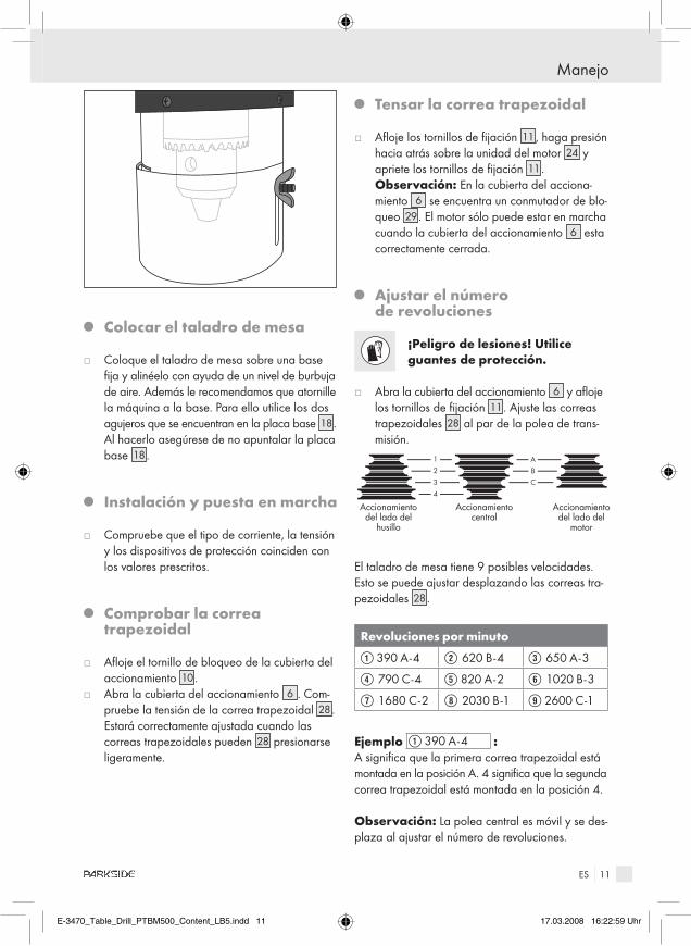
Q Tensar la correa trapezoidal
j Afloje los tornillos de fijación 11, haga presión hacia atrás sobre la unidad del motor 24 y apriete los tornillos de fijación 11.
Observación: En la cubierta del acciona-miento 6 se encuentra un conmutador de blo-queo 29. El motor sólo puede estar en marcha cuando la cubierta del accionamiento 6 esta correctamente cerrada.
Q ajustar el número de revoluciones
¡Peligro de lesiones! Utilice guantes de protección.
j Abra la cubierta del accionamiento 6 y afloje los tornillos de fijación 11. Ajuste las correas trapezoidales 28 al par de la polea de trans-misión.
ABC
1
2
3
4
Accionamiento del lado del
husillo
Accionamiento central
Accionamiento del lado del
motor
El taladro de mesa tiene 9 posibles velocidades. Esto se puede ajustar desplazando las correas tra-pezoidales 28.
revoluciones por minuto
Q 390 A - 4 W 620 B - 4 E 650 A - 3
R 790 C - 4 T 820 A - 2 Y 1020 B - 3
U 1680 C - 2 I 2030 B - 1 O 2600 C - 1
Ejemplo Q 390 A - 4 : A significa que la primera correa trapezoidal está montada en la posición A. 4 significa que la segunda correa trapezoidal está montada en la posición 4.
Observación: La polea central es móvil y se des-plaza al ajustar el número de revoluciones.
E-3470_Table_Drill_PTBM500_Content_LB5.indd 11 17.03.2008 16:22:59 Uhr

12 ES
Manejo
j Tense las correas trapezoidales 28 como se describe en el capítulo “tensar correas trape-zoidales”.
Q regular la mesa de taladrado
j Afloje los tornillos de fijación 16 y lleve la mesa de taladrado 19 a la altura deseada (p. ej. inclínela lateralmente cuando quiera trabajar una pieza de trabajo alta, que se sujetará directamente a la placa base 18).
j También puede inclinar la mesa de taladrado 19 hasta 45° a la izquierda o la derecha. Para ello afloje el tornillo 22 con una llave 19 y mantenga la mesa de taladrado en la posición deseada. Vuelva a apretar el tornillo 22.
Q Seleccionar profundidad de la broca
El tope de profundidad con escala 12 permite seleccionar la profundidad de la broca. j Desatornille los tornillos de sujeción 16 de la
mesa de taladrado 19. Desplace la mesa de taladrado 19 hasta que la pieza sujeta se en-cuentre en la punta de la broca.
Ajuste la profundidad de la fresa como se indica a continuación.j Suelte la tuerca de fijación 8 .j Gire la escala 12 del preselector de profundidad
de broca hasta que la profundidad deseada se encuentre en la marca de la flecha.
j Suelte el tornillo de fijación 8 .
Observación: El lado izquierdo de la escala 12 indica la profundidad de la broca. El lado derecho de la escala 12 indica el curso de perforación res-tante.
Q Cambiar / tensar la herramienta
¡aDVErTEnCIa! Antes de realizar trabajos en el aparato, desenchúfelo de la toma de corriente.
Esta medida de precaución evita que el aparato se ponga en marcha accidentalmente. j Pliegue hacia arriba el dispositivo de protec-
ción 5 .j Afloje las mordazas del portabrocas 3 con la
llave para el portabrocas 32.j Retire la herramienta.j Introduzca la broca y tense las mordazas de
retención del portabrocas 3 con la llave para el portabrocas 32.
Asegúrese de que la broca está centrada sujeta en el portabrocas.
Q Tensar la pieza de trabajo en el tornillo de banco
Para abrir las mordazas de sujeción 14 gire la ma-nilla 21 en el sentido contrario al de las agujas del reloj. Ponga la pieza de trabajo entre las mordazas de sujeción 14 y fíjela girando la manilla 21 en el sentido de las agujas del reloj.
Observación: El tornillo de banco 13 sirve para tensar piezas de trabajo planas y con cantos. Los tubos sólo pueden tensarse en determinadas condi-ciones.
Q Conectar y desconectar el taladro de mesa
Conexión:j Pulse el interruptor de CONEXIÓN 2 .
Desconexión:j Pulse el interruptor de DESCONEXIÓN 1 .
Q Taladrar
Gire el mango 7 de uno de los tres brazos para elevación de la broca en el sentido contrario al de las agujas del reloj. El portabrocas 3 desciende. Gire el mango hasta que la broca se hunda en la pieza de trabajo con la profundidad deseada, véase también fig. D.
E-3470_Table_Drill_PTBM500_Content_LB5.indd 12 17.03.2008 16:22:59 Uhr

13 ES
Manejo / Mantenimiento y limpieza / Eliminación / Informaciones
Después de realizar adecuadamente la perforación lleve el mango 7 de nuevo a la posición inicial girándolo en el sentido contrario.
Observación: Tenga en cuenta que el mango cuenta con una contrapresión. Si suelta el mango, se moverá rápidamente a la posición inicial.
Q Trabajar materiales / Ejemplo
Trabajado de metales:j Para metales duros y / o para un diámetro de
perforación grande seleccione un número bajo de revoluciones.
Trabajado de madera:j Utilice una mascarilla antipolvo, el polvo de la
madera es perjudicial para la salud.
Otros ejemplos de uso Trabajado de baldosas de cerámica / plásticos: j Trabaje con un número de revoluciones más
bajo. Utilice una broca adecuada con punta de alineación.
Q Mantenimiento y limpieza
¡aDVErTEnCIa! Antes de realizar trabajos en el aparato, desenchúfelo de la toma de corriente. Esta medida de precaución evita que el aparato se ponga en marcha accidentalmente.
j Limpie regularmente el dispositivo inmediata-mente después de finalizar el trabajo.
j Utilice un paño seco para limpiar la carcasa, no use nunca bencina, disolventes o detergentes.
j Retire virutas, polvo y suciedad, en caso nece-sario con un aspirador.
j Lubrique con regularidad las piezas móviles.j Asegúrese de que no caiga lubricante en el in-
terruptor 1 , 2 , las correas trapezoidales 28 y poleas de transmisión 25, 26 , 27 .
Q Eliminación
El embalaje se compone de materiales reciclables que puede desechar en los puntos locales de recogida selectiva.
¡no tire las herramientas eléctri-cas en la basura doméstica!
Según la Directiva europea 2002 / 96 / CE sobre residuos de aparatos eléctricos y electrónicos y en cumplimiento con el derecho nacional, las herra-mientas eléctricas usadas se tienen que separar y reciclar sin dañar el medioambiente.
Para deshacerse de un aparato que ya no sirva pregunte a las autoridades locales o municipales.
Q Informaciones
Q asistencia
Consulte los puntos de atención al cliente de su país en la documentación de la garantía.
J Haga reparar los aparatos únicamente por personal técnico cualificado y con repuestos originales. Así se garantiza que el aparato seguirá siendo seguro.
J Si es necesario cambiar el enchufe o el cable de alimentación, encargue este trabajo al fabricante del aparato o a su servicio de atención al cliente. Así se garantiza que el aparato seguirá siendo seguro.
E-3470_Table_Drill_PTBM500_Content_LB5.indd 13 17.03.2008 16:23:00 Uhr
14 ES
Informaciones
Q Declaración de conformidad / Fabricante
Nós, Kompernaß GmbH, Burgstr. 21, 44867 Bochum, Alemania, declaramos que este produto cumpre as seguintes directivas CE:
Directiva sobre maquinaria (98 / 37 / EG)
Directriz de baja tensión UE (2006 / 95 / EG)Probado de acuerdo con acc.toEN 61029 - 1: 2000 + A11 + A12
Compatibilidad electromagnética (2004 / 108 / EG)Probado de acuerdo con acc.toEN 55014 - 1: 2000 + A1 + A2EN 55014 - 2: 1997 + A1EN 61000 - 3 - 2: 2000 + A2EN 61000 - 3 - 3: 1995 + A1
Tipo / denominación del producto:Parkside Taladro de mesa PTBM 500
Bochum, 31.03.2008
Hans Kompernaß - Gerente -
Queda reservado el derecho a realizar modificaciones técnicas
para el perfeccionamiento del dispositivo.
E-3470_Table_Drill_PTBM500_Content_LB5.indd 14 17.03.2008 16:23:00 Uhr

15 IT/MT
Contenuto
Introduzione Utilizzo secondo le finalità d’uso ................................................................................Pagina 16Dotazione ......................................................................................................................Pagina 16Ambito di fornitura ........................................................................................................Pagina 17Dati tecnici ....................................................................................................................Pagina 17
Indicazioni di sicurezza ................................................................................Pagina 17Lavoro sicuro .................................................................................................................Pagina 18 Indicazioni di sicurezza specifiche per trapani da banco ........................................Pagina 19
Funzionamento Montaggio ....................................................................................................................Pagina 20 Posizionamento del trapano a banco.........................................................................Pagina 20 Installazione e messa in esercizio ...............................................................................Pagina 21 Verifica della cinghia trapezoidale .............................................................................Pagina 21 Tensionamento della cinghia trapezoidale ................................................................Pagina 21 Regolazione del numero di giri ...................................................................................Pagina 21 Regolazione del banco di trapanatura ......................................................................Pagina 21 Preselezione della profondità di foratura ...................................................................Pagina 22 Cambio utensile / Tensionamento della punta ...........................................................Pagina 22 Bloccaggio del pezzo da lavorare nella morsa a vite .............................................Pagina 22 Accensione e spegnimento del trapano a banco ......................................................Pagina 22 Esecuzione della foratura ............................................................................................Pagina 22 Lavorazione di materiali / Esempi ...............................................................................Pagina 22
Manutenzione e pulizia ................................................................................Pagina 23
Smaltimento ...........................................................................................................Pagina 23
Informazioni Assistenza......................................................................................................................Pagina 23 Dichiarazione di conformità / Produttore ...................................................................Pagina 24
E-3470_Table_Drill_PTBM500_Content_LB5.indd 15 17.03.2008 16:23:00 Uhr

16 IT/MT
Introduzione
Trapano da banco PTBM 500
Q Introduzione
Prima della messa in servizio dell’appa-recchio prendere dimestichezza con le sue funzioni e informarsi sul corretto
utilizzo degli utensili elettrici. Al riguardo leggere le seguenti istruzioni per l’uso, da conservare con cura. L’apparecchio deve essere accompagnato dalla documentazione completa anche in caso di cessione a terzi.
Q Utilizzo secondo le finalità d’uso
Questo apparecchio è destinato alla foratura di pezzi in metallo, legno e plastica nonché di piastrelle previa utilizzo di punte cilindriche ø 1,5 mm per un diametro di foratura massimo di ø 16 mm. Ogni altro utilizzo o modifica dell’apparecchio si considera come non conforme alle finalità d’uso e può provocare notevoli pericoli. Il produttore non risponde di eventuali danni che dovessero derivare da un utilizzo dellíapparec-
chio non conforme alla destinazione dëuso. Questo apparecchio non è destinato allíutilizzo commerciale.
Q Dotazione
1 Interruttore di spegnimento2 Interruttore di accensione3 Pinza serrapunta4 Mandrino portapunta5 Dispositivo di protezione6 Coperchio meccanismo di trasmissione7 Impugnatura / Guida del mandrino con 3
bracci di sollevamento 8 Vite di fermo preselezione profondità di foratura9 Supporto chiave per pinza serrapunta
10 Tappo a vite coperchio del meccanismo di trasmissione
11 Viti di fermo (su entrambi i lati)12 Finecorsa di profondità con scala13 Morsa a vite14 Ganasce15 Messa in scala angolare16 Vite di serraggio17 3 viti di montaggio17 a 3 rondelle
nel presente manuale di istruzioni per l’uso vengono utilizzati i seguenti pittogrammi / simboli:
Leggere il manuale di istruzioni per l’uso!
Portare una mascherina per la polvere, occhiali protettivi e guanti protettivi.
Rispettare le avvertenze e le indicazioni per la sicurezza!
Tenere lontani i bambini e altre persone durante l’uso dell’elettroutensile.
Attenzione, rischio di scossa elettrica! Tensione elettrica pericolosa – pericolo di morte!
Tenere l’apparecchio al riparo da pioggia o umidità. La penetrazione di acqua nell’apparecchio elettrico aumenta il rischio di scossa elettrica.
Pericolo di esplosione!
I danni all’apparecchio, al cavo o alla spina com-portano il pericolo di morte a causa di scossa elettrica. Controllare regolarmente le condizioni dell’appa-recchio, del cavo e della spina.
V~ Volt (tensione alternata) Smaltire l’imballaggio dell’apparecchio in modo ecocompatibile!
W Watt (potenza attiva)
E-3470_Table_Drill_PTBM500_Content_LB5.indd 16 17.03.2008 16:23:00 Uhr

17 IT/MT
Introduzione / Indicazioni di sicurezza
17 b 3 anelli elastici18 Piastra di base19 banco di trapanatura20 2 viti per morsa20 a 4 rondelle20 b 2 dadi21 Nottola22 Vite (per inclinazione del banco di trapanatura)23 Tubo montante24 Unità motore25 Puleggia motrice su lato motore26 Puleggia motrice centrale27 Puleggia motrice su lato mandrino28 Cinghia trapezoidale29 Interruttore di blocco30 1 chiave a brugola esagonale 31 2 viti a testa esagonale32 Chiave per pinza serrapunta
Q ambito di fornitura
Si prega di controllare la merce fornita immediata-mente dopo avere disimballato l’apparecchio:
1 piastra di base1 tubo montante3 viti di montaggio / 3 rondelle / 3 anelli elastici1 banco di trapanatura con vite di serraggio1 morsa a vite2 viti per morsa a vite / 4 rondelle / 2 dadi 1 unità motore / trasmissione3 bracci di sollevamento 1 pinza serrapunta1 dispositivo di protezione1 chiave a brugola esagonale1 chiave per pinza serrapunta1 istruzioni d’uso1 quaderno “Garanzia ed assistenza “
Q Dati tecnici
Alimentazione: 230 V ~ 50 HzPotenza nominale: 500 WNumero di giri motore: n0 1440 min-1
Pinza serrapunta: ø 1,5 - 16 mmCorsa mandrino: 50 mm
Banco di trapanatura: 170 x 170 mm / 45° - 0° - 45°
Numero di giri mandrino: n0 390 - 2600 min-1
Massa, incluse parti asportabili: 27 kg
Informazioni relative a rumore e vibrazioni:Rumorosità rilevata con ponderazione di frequenza A.Livello di pressione sonora: 72 dB (A)Livello di rumore: 85 dB (A)Scostamento K=3 dB. Durante il lavoro il livello di rumore può superare 88 dB (A).
Indossare un idoneo dispositivo di protezione auricolare!
PTBM 500 KH3133Date of manufacture: 03-2008230 V ~ 50 Hz · 500 W · n0 1440 / min
Kompernaß GmbH 44867 Bochum Germany� www.kompernass.com
max. 50 mm
ø max. 16 mm
ID :00 0 0 0 21765
Indicazioni di sicurezza
J aTTEnZIOnE! Utilizzando apparecchi elettrici, devono essere osservate tutte le indicazioni di sicurezza di seguito menzionate a protezione da rischi di scossa elettrica, di lesione o di incendi. Leggere ed osservare tali indicazioni prima di utilizzare líapparecchio, e conservarle in buono stato.
E-3470_Table_Drill_PTBM500_Content_LB5.indd 17 17.03.2008 16:23:01 Uhr
18 IT/MT
Indicazioni di sicurezza
Q Lavoro sicuro
1. Mantenere in ordine l’area di lavoro.J Il disordine nell’area di lavoro può provocare
incidenti. 2. Tenere conto degli influssi dell’am-
biente circostante.J Non esporre apparecchi elettrici alla pioggia.J Non utilizzare utensili elettrici in un
ambiente umido o bagnato.
J Assicurarsi che l’area di lavoro sia bene illuminata.
J Non utilizzare apparecchi elettrici in aree dove sussistono pericoli di incendio o di esplosione.
3. Proteggersi dalla possibilità di scossa elettrica.
J Fare in modo che il corpo non tocchi parti messe a terra (ad esempio tubi, caloriferi, fornelli elettrici, refrigeratori).
4. Tenere lontane le persone estranee.J Fare in modo che nessuna persona
estranea, in modo particolare bam-bini, tocchi l’apparecchio elettrico o
il cavo. Tenere le persone estranee lontane dall’area di lavoro.
5. Conservare in modo sicuro gli appa-recchi elettrici inutilizzati.
J Gli apparecchi elettrici inutilizzati devono es-sere posti in luogo asciutto, in posizione elevata oppure al chiuso, e al di fuori della portata dei bambini.
6. non sovraccaricare l’apparecchio elettrico.
J Si lavora meglio e in maggiore sicurezza nella gamma di carico indicata.
7. Utilizzare l’apparecchio elettrico cor-retto.
J Non utilizzare per lavori pesanti apparecchi forniti di una tensione più bassa.
J Non utilizzare l’apparecchio per scopi che non previsti. Ad esempio, non utilizzare una sega circolare manuale per tagliare piloni o ceppi.
8. Indossare l’abbigliamento adatto.J Non indossare abiti ampi o gioielli, essi
potrebbero impigliarsi nelle parti in movimento.J In caso di lavorazione eseguita all’aperto si
suggerisce di indossare calzature antisdrucciolo.J Gli operatori con capelli lunghi devono sempre
indossare una rete sui capelli. 9. Utilizzare l’equipaggiamento
di sicurezza.J Indossare occhiali di protezione.J In caso di lavori che generano polvere, indos-
sare una mascherina antipolvere.10. non utilizzare il cavo per scopi
per i quali esso non è desti-nato.
J Non utilizzare il cavo per estrarre la spina dalla presa. Proteggere il cavo da calore, olio e angoli acuti.
11. Bloccare il pezzo in lavorazione.J Per fissare il pezzo in lavorazione utilizzare
dispositivi di bloccaggio oppure una morsa a vite. In questo modo il pezzo è trattenuto in modo più sicuro che con una mano.
12. Evitare una postura non naturale.J Assicurarsi di lavorare in una postura sicura e
mantenere sempre l’equilibrio.13. avere buona cura degli utensili.J Per lavorare meglio e in maggiore sicurezza,
mantenere gli utensili da taglio affilati e puliti.J Osservare le indicazioni fornite relativamente
sulla lubrificazione e il cambio dell’utensile.J Controllare regolarmente il cavo di alimenta-
zione dell’utensile elettrico, e in caso di dan-neggiamento dello stesso, farlo riparare da un tecnico specializzato.
J Controllare con regolarità le prolunghe e so-stituirle qualora fossero danneggiate.
J Mantenere le impugnature asciutte, pulite e senza olio o grasso.
14. Estrarre la spina dalla presa elettrica:J In caso di mancato utilizzo dell’utensile elettrico,
prima di ogni intervento di manutenzione e in caso di cambio utensili quali ad esempio lama, punta o fresatrice.
15. non lasciare inserite chiavette del mandrino.
J Prima di avviare l’apparecchio, verificare che nessuna chiavetta o dispositivo di regolazione siano inseriti.
E-3470_Table_Drill_PTBM500_Content_LB5.indd 18 17.03.2008 16:23:01 Uhr

19 IT/MT
Indicazioni di sicurezza
16. Evitare un avvio involontario.J Assicurarsi che l’interruttore sia disinserito al
momento di inserire la spina.17. Utilizzare la prolunga per all’aperto.J All’aperto utilizzare solamente cavi e prolunghe
approvati per tale utilizzo e contrassegnati in modo corrispondente.
18. rimanere attenti.J Fare sempre estrema attenzione a ciò che si
fa e accostarsi al lavoro sempre in modo co-sciente. Non lavorare con un utensile elettrico quando non si è concentrati.
19. Controllare l’utensile elettrico per verificare eventuali danni.
J Prima di utilizzare l’utensile elettrico, i disposi-tivi di protezione devono essere controllati con attenzione per appurare la loro perfetta funzionalità.
J Verificare se le parti in movimento funzionano perfettamente e non si bloccano, oppure se i componenti sono danneggiati. Tutte le parti devono essere montate correttamente e soddi-sfare tutte le condizioni che garantiscono un funzionamento perfetto dell’utensile elettrico.
J A meno di indicazioni diverse riportate nelle istruzioni d’uso, i dispositivi e gli elementi di protezione devono essere riparati o sostituiti da un’officina specializzata per ristabilire la loro destinazione d’uso,.
J Gli interruttori danneggiati devono essere so-stituiti presso un’officina del Centro di Assistenza.
J Non utilizzare utensili elettrici che non si pos-sano accendere e spegnere regolarmente.
20. aTTEnZIOnE!J L’utilizzo di altri utensili sostitutivi e di altri ac-
cessori può rappresentare un pericolo di lesio-ne per l’utilizzatore.
21. Fare riparare l’apparecchio elettrico da un elettricista specializzato.
J Questo apparecchio è stato realizzato in con-formità alle norme specifiche di sicurezza. Eventuali riparazioni possono essere eseguite solamente da un elettricista specializzato ed utilizzando pezzi di ricambio originali; in caso contrario sussiste il pericolo di incidenti.
Indicazioni di sicurezza specifiche per trapani da banco
J aTTEnZIOnE: Un’eccessiva pressione sovraccarica il motore e riduce il numero di giri.
J Utilizzare solamente utensili affilati.J Raffreddare la punta con un liquido adatto.J Per fori eseguiti nell’acciaio inossidabile è
necessario utilizzare punte speciali.J Prima di ogni utilizzo verificare che la pinza
serrapunta 3 , il banco di trapanatura 19 e gli avvitamenti abbiano sedi ben fissate.
J Verificare la funzionalità dell’interruttore di blocco 29 posto sotto il coperchio del mecca-nismo di trasmissione 6 : all’apertura del co-perchio del meccanismo di trasmissione 6 il trapano a banco deve essere disinserito.
J Non rimuovere mai i trucioli con la mano, giacché in questo caso sussiste il pericolo di lesione.
J Durante il lavoro non indossare guanti, giacché in caso contrario sussiste il pericolo di aggrovi-gliamento.
J aVVErTIMEnTO! Fare attenzione a che il contatto o la respirazione di polveri rappresenta un pericolo per l’operatore e le persone che si trovano nei pressi. Prendere le misure più idonee con riferimento alle polveri.
J aVVErTIMEnTO! Mantenere sempre pulita la postazione di lavoro. Le miscele di materiali sono infatti particolarmente pericolose. Ad esempio, la polvere di metallo leggero può provocare un incendio o un’esplosione.aTTEnZIOnE! PErICOLO DI SCOSSa
ELETTrICa a CaUSa DI METaLLO LEG-GErO! In caso di lavorazione di metallo può posarsi polvere conduttrice all’interno dell’appa-recchio. Fare funzionare l’apparecchio solamente attraverso un salvavita FI (corrente di intervento 30 mA).
J Non utilizzare materiale contenente asbesto. L’asbesto è ritenuto un materiale cancerogeno.
J Non lavorare materiali umidi o aventi superfici bagnate.
J Evitare qualsiasi avvio involontario dell’appa-recchio.
E-3470_Table_Drill_PTBM500_Content_LB5.indd 19 17.03.2008 16:23:01 Uhr
20 IT/MT
Indicazioni di sicurezza / Funzionamento
J Non utilizzare mai l’apparecchio per scopi diversi da quelli previsti.
J Condurre sempre il cavo di alimentazione da dietro l’apparecchio.
Q Funzionamento
Q Montaggio
Il trapano da banco viene fornito completamento smontato.j Anzitutto pulire i componenti sui quali è stata
applicata la protezione antiruggine (tubo mon-tante 23, il piede, la morsa a vite 13 e la pinza serrapunta 3 ), ad esempio con un panno asciutto.
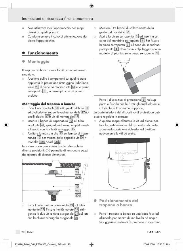
Montaggio del trapano a banco:j Porre il tubo montante 23 sulla piastra di base 18
ed avvitarlo nel seguente ordine: rondelle 17 a / anelli elastici 17 b viti di montaggio 17.
j Inserire il banco di trapanatura 19 sul tubo montante 23, spingerlo in basso completamente e fissarlo con la vite di serraggio 16.
j Avvitare la morsa a vite 13 sul banco di trapa-natura 19 per mezzo delle apposite viti 20 / rondelle 20 a / dadi 20 b .
La morsa a vite può essere fissata alle asole in diverse posizioni. Ciò permette di tensionare pezzi da lavorare di diverse dimensioni.
2013
19
20 b20 a
20 a
j Porre l’unità motore premontata 24 sul tubo montante 23. Fissare l’unità motore 24, strin-gendo le due viti a testa esagonale 31 sul lato con la chiave a brugola esagonale 30.
j Montare i tre bracci di sollevamento della guida del mandrino 7 .
j Aprire la pinza serrapunta 3 ed inserirla sul cono del mandrino portapunta 4 . Per fissare la pinza serrapunta 3 sul cono del mandrino portapunta 4 , dare alcuni colpi leggeri con un martello di plastica sulla pinza serrapunta 3 .
Porre il dispositivo di protezione 5 nel sup-porto e fissarlo con le 3 viti, gli anelli elastici e i dadi che si trovano nel supporto,.
La parte inferiore del dispositivo di protezione può essere regolata in altezza. j A questo scopo allentare le viti ad alette, por-
tare la parte inferiore del dispositivo di prote-zione nella posizione richiesta, ed avvitare nuovamente le viti ad alette.
Q Posizionamento del trapano a banco
j Porre il trapano a banco su una base fissa ed allinearlo per mezzo di una livella ad acqua. Si suggerisce inoltre di fissare bene la macchina
E-3470_Table_Drill_PTBM500_Content_LB5.indd 20 17.03.2008 16:23:01 Uhr
21 IT/MT
Funzionamento
su una base. Utilizzare a questo proposito i due fori nella piastra di base 18. A questo scopo assicurarsi che la piastra di base 18 non sia serrata in misura eccessiva.
Q Installazione e messa in esercizio
j Verificare se la tipologia di energia elettrica, di tensione e di protezione corrispondono con i valori prescritti.
Q Verifica della cinghia trapezoidale
j Allentare il tappo a vite del coperchio del mec-canismo di trasmissione 10.
j Aprire il coperchio del meccanismo di trasmis-sione 6 . Verificare il tensionamento della cin-ghia trapezoidale 28. Essa è regolata in modo corretto se la cinghia trapezoidale 28 si può premere leggermente.
Q Tensionamento della cinghia trapezoidale
j Allentare le viti di fermo 11, premere l’unità motore 24 all’indietro ed avvitare le viti di fermo 11.
nota: Nel coperchio del meccanismo di trasmis-sione 6 si trova un interruttore di blocco 29. Il motore può partire solamente se il coperchio del meccanismo di trasmissione 6 è stato chiuso in modo corretto.
Q regolazione del numero di giri
Pericolo di lesione! Indossare guanti di protezione!
j Aprire il coperchio del meccanismo di trasmis-sione 6 ed allentare le viti di fermo 11. Porre la cinghia trapezoidale 28 sulla coppia di puleggia motrice desiderata.
ABC
1
2
3
4
Azionamento sul lato mandrino
Azionamento centrale
Azionamento sul lato motore
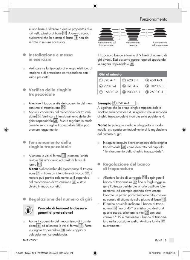
Il trapano a banco è fornito di 9 livelli di numero di giri diversi. Essi possono essere regolati spostando la cinghia trapezoidale 28.
Giri al minuto
Q 390 A - 4 W 620 B - 4 E 650 A - 3
R 790 C - 4 T 820 A - 2 Y 1020 B - 3
U 1680 C - 2 I 2030 B - 1 O 2600 C - 1
Esempio Q 390 A - 4 : A significa che la prima cinghia trapezoidale è montata sulla posizione A. 4 significa che la seconda cinghia trapezoidale è montata sulla posizione 4.
nota: La puleggia media è alloggiata in modo mobile, e si sposta contestualmente al la regolazione del numero di giri.
j In seguito eseguire il tensionamento della cinghia trapezoidale 28, come descritto nel capitolo “Tensionamento della cinghia trapezoidale”.
Q regolazione del banco di trapanatura
j Allentare la vite di serraggio 16 e spingere il banco di trapanatura 19 fino a fargli raggiun-gere l’altezza desiderata o farlo oscillare late-ralmente, ad esempio quando deve essere lavorato un pezzo particolarmente alto, che vie-ne serrato direttamente sulla piastra di base 18.
j E’ anche possibile inclinare il banco di trapa-natura 19 fino al 45° a sinistra o a destra. A questo scopo, allentare la vite 22 con una chiave n° 19 e mantenere il banco di trapana-tura nella posizione scelta. Avvitare la vite 22 nuovamente.
E-3470_Table_Drill_PTBM500_Content_LB5.indd 21 17.03.2008 16:23:02 Uhr

22 IT/MT
Funzionamento
Q Preselezione della profondità di foratura
Il finecorsa di profondità con scala 12 permette di eseguire la preselezione della profondità di foratura. j Allentare la vite di serraggio 16 del banco di
trapanatura 19. Spostare il banco di trapana-tura 19 fino a che il pezzo bloccato non si posi sulla punta.
Regolare la profondità di foratura nel modo seguente.j Allentare la vite di fermo 8 .j Ruotare la scala 12 per la preselezione della
profondità di foratura fino a che la profondità di foratura desiderata non venga a trovarsi sul-la freccia.
j Fissare la vite di fermo 8 .
nota: Il lato sinistro della scala 12 mostra la pro-fondità di foratura. Il lato destro della scala 12 mo-stra la corsa di foratura rimasta.
Q Cambio utensile / Tensionamento della punta
aTTEnZIOnE! Prima di eseguire interventi sull’apparecchio, estrarre sempre la spina dalla presa elettrica. Ciò impedisce un avvio involontario dell’apparecchio. j Ribaltare il dispositivo di protezione 5 verso
l’alto.j Allentare le ganasce di fermo della pinza
serrapunta 3 con la chiave per pinza serra-punta 32.
j Rimuovere l’utensile.j Inserire la punta e serrare le ganasce di fermo
della pinza serrapunta 3 con la chiave per pinza serrapunta 32.
Fare sempre attenzione a che la punta sia bloccata al centro della pinza serrapunta.
Q Bloccaggio del pezzo da lavorare nella morsa a vite
Per aprire le ganasce 14, ruotare le nottola 21 in senso antiorario. Porre il pezzo tra le ganasce 14 e bloccarlo previa rotazione della nottola 21 in senso orario.
nota: La morsa a vite 13 serve allo scopo di bloccare pezzi piatti ed angolati. I tubi possono essere bloccati solamente in certe condizioni.
Q accensione e spegnimento del trapano a banco
accensione:j Premere l’interruttore di accensione 2 .
Spegnimento:j Premere l’interruttore di spegnimento 1 .
Q Esecuzione della foratura
Ruotare l’impugnatura 7 in senso antiorario presso uno dei tre bracci di sollevamento. La pinza serra-punta 3 scende. Ruotare l’impugnatura fino a che la punta si immerge nel pezzo per la profondità desiderata, a questo proposito vedi anche la fig. D.Dopo avere eseguito la foratura, riportare l’impu-gnatura 7 nuovamente in direzione opposta nella posizione di partenza.
nota: Fare attenzione a che l’impugnatura disponga di una contropressione. Nel caso in cui l’utilizzatore lasci andare l’impugnatura, essa torna velocemente verso la posizione di partenza.
Q Lavorazione di materiali / Esempi
Lavorazione di metallo:j Per metalli duri e/o per diametri di foratura di
notevoli dimensioni si scelga un numero di giri basso.
E-3470_Table_Drill_PTBM500_Content_LB5.indd 22 17.03.2008 16:23:02 Uhr
23 IT/MT
Funzionamento / Manutenzione e pulizia / Smaltimento / Informazioni
Lavorazione di materiali in legno:j Utilizzare una mascherina antipolvere, le pol-
veri di legno sono pericolose per la salute.
Ulteriori esempi di utilizzo Lavorazione di piastrelle di ceramica / di plastica: j Lavorare con un numero di giri basso. Utilizzare
una punta adatta con punta di centraggio.
Q Manutenzione e pulizia
aTTEnZIOnE! Prima di eseguire interventi sull’apparecchio, estrarre sempre la spina dalla presa elettrica. Ciò impedisce un avvio involontario dell’apparecchio.
j Pulire con regolarità l’apparecchio, e ciò subito dopo la conclusione della lavorazione.
j Per la pulizia dell’alloggiamento utilizzare un panno asciutto; non utilizzare mai benzina, solventi o detersivi.
j Rimuovere trucioli, polvere e sporco, se neces-sario con un aspirapolvere.
j Lubrificare con regolarità gli elementi mobili.j Assicurarsi che i lubrificanti utilizzati non giun-
gano sugli interruttori 1 , 2 , sulla cinghia tra-pezoidale 28 e sulle pulegge motrici 25, 26, 27.
Q Smaltimento
L’imballaggio è composto da materiali ecologici, che possono essere smaltiti presso i siti di riciclaggio locali.
non gettare gli utensili elettrici nei rifiuti domestici!
In conformità alla direttiva europea 2002 / 96 / EG sui rifiuti di apparecchiature elettriche ed elettroniche e relativa trasposizione nel diritto nazionale, gli utensili elettrici usati devono essere raccolti separa-tamente e riciclati in maniera compatibile con l’ambiente.
Informazioni sulle possibilità di smaltimento di ap-parecchi giunti al termine della loro vita utile sono disponibili presso le amministrazioni comunali.
Q Informazioni
Q assistenza
Il centro di assistenza competente per ciascun paese è indicato nei documenti di garanzia.
J affidare la riparazione dell’apparec-chio esclusivamente a personale spe-cializzato e qualificato e con pezzi di ricambio originali, a garanzia della sicu-rezza dell’apparecchio.
J La sostituzione della spina o del cavo di alimentazione deve essere eseguita esclusivamente dal fabbricante dell’apparecchio o dal relativo servizio clienti, a garanzia della sicurezza dell’appa-recchio.
E-3470_Table_Drill_PTBM500_Content_LB5.indd 23 17.03.2008 16:23:02 Uhr

24 IT/MT
Informazioni
Q Dichiarazione di conformità / Produttore
Noi, la Kompernaß GmbH, Burgstr. 21, 44867 Bochum, Germania, dichiariamo la conformità di questo prodotto con le seguenti normative europee:
normativa per le macchine (98 / 37 / EG)
normativa CE per bassa tensione (2006 / 95 / EG)Testato ai sensi di Tested acc.toEN 61029 - 1: 2000 + A11 + A12
Compatibilità elettromagnetica (2004 / 108 / EG)Testato ai sensi di Tested acc.toEN 55014 - 1: 2000 + A1 + A2EN 55014 - 2: 1997 + A1EN 61000 - 3 - 2: 2000 + A2EN 61000 - 3 - 3: 1995 + A1
Tipo / Descrizione del prodotto: Parkside Trapano da banco PTBM 500
Bochum, 31.03.2008
Hans Kompernaß- Amministratore -
Sono riservate modifiche tecniche per lo sviluppo dell’apparecchio.
E-3470_Table_Drill_PTBM500_Content_LB5.indd 24 17.03.2008 16:23:02 Uhr

25 GB/MT
Introduction Proper use .....................................................................................................................Page 26Features and equipment ...............................................................................................Page 26Included items ...............................................................................................................Page 27Technical information ...................................................................................................Page 27
Safety advice Working safely ..............................................................................................................Page 27 Safety advice relating specifically to this device .......................................................Page 29
Operation Assembly .......................................................................................................................Page 29 Placing the bench press drill in a suitable working position .....................................Page 30 Installation and bringing into use ................................................................................Page 30Checking the V-belts .....................................................................................................Page 30Tensioning the V-belts ...................................................................................................Page 31Setting the speed .........................................................................................................Page 31Setting the drilling table ...............................................................................................Page 31Setting the drilling depth ..............................................................................................Page 31 Exchanging tools / Inserting the drill ...........................................................................Page 31 Clamping the workpiece in the vice ............................................................................Page 32 Switching the bench press drill on and off .................................................................Page 32Drilling ...........................................................................................................................Page 32 Drilling different materials / Some examples ..............................................................Page 32
Servicing and cleaning .................................................................................Page 32
Disposal ......................................................................................................................Page 32
Information Service centre ...............................................................................................................Page 33 Declaration of conformity / Producer ..........................................................................Page 33
Table of content
E-3470_Table_Drill_PTBM500_Content_LB5.indd 25 17.03.2008 16:23:02 Uhr
26 GB/MT
Introduction
Bench press drill PTBM 500
Q Introduction
Please make sure you familiarise your-self fully with the way the device works before you use it for the first time and
that you understand how to handle electrical pow-er tools correctly. To help you do this please read the accompanying operating instructions. Keep these instructions in a safe place. If you pass the device on to anyone else, please ensure that you also pass on all the documentation.
Q Proper use
This device is intended for drilling in metal, wood, plastic and tiles using parallel-shank drill bits (ø 1.5 mm to a maximum ø 16 mm). Any other use or modification to the device shall be considered as improper use and could give rise to considera-ble risk of accident. We will not accept liability for loss or damage arising from improper use. The de-vice is intended for domestic use only.
Q Features and equipment
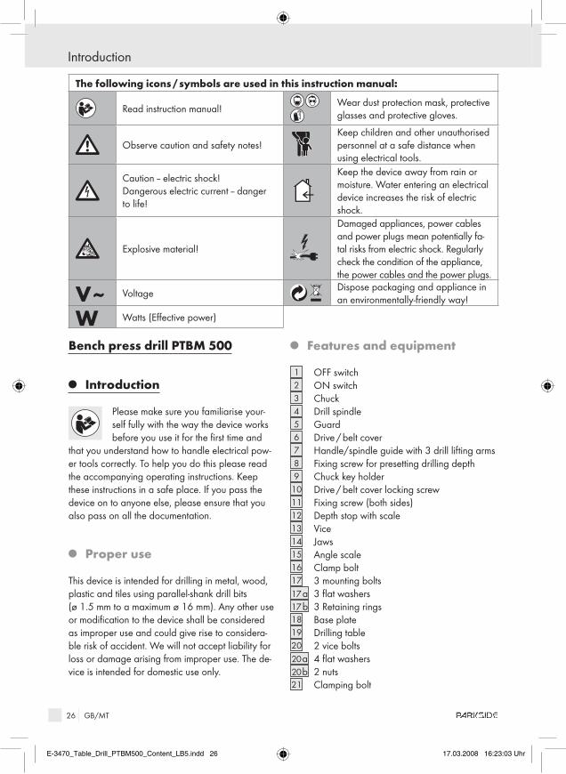
1 OFF switch2 ON switch3 Chuck4 Drill spindle5 Guard6 Drive / belt cover7 Handle/spindle guide with 3 drill lifting arms8 Fixing screw for presetting drilling depth9 Chuck key holder
10 Drive / belt cover locking screw11 Fixing screw (both sides)12 Depth stop with scale13 Vice14 Jaws15 Angle scale16 Clamp bolt17 3 mounting bolts17 a 3 flat washers17 b 3 Retaining rings18 Base plate19 Drilling table20 2 vice bolts20 a 4 flat washers20 b 2 nuts21 Clamping bolt
The following icons / symbols are used in this instruction manual:
Read instruction manual! Wear dust protection mask, protective glasses and protective gloves.
Observe caution and safety notes!Keep children and other unauthorised personnel at a safe distance when using electrical tools.
Caution – electric shock!Dangerous electric current – danger to life!
Keep the device away from rain or moisture. Water entering an electrical device increases the risk of electric shock.
Explosive material!
Damaged appliances, power cables and power plugs mean potentially fa-tal risks from electric shock. Regularly check the condition of the appliance, the power cables and the power plugs.
V~ VoltageDispose packaging and appliance in an environmentally-friendly way!
W Watts (Effective power)
E-3470_Table_Drill_PTBM500_Content_LB5.indd 26 17.03.2008 16:23:03 Uhr

27 GB/MT
Introduction / Safety advice
22 Bolt (drilling table inclination)23 Column24 Motor unit25 Drive wheel (motor side)26 Middle drive wheel27 Drive wheel (spindle side)28 V-belt29 Interlock switch30 1 Hex Allen key 31 2 hexagon socket head bolts32 Chuck key
Q Included items
Check that all the items and accessories are present immediately after unpacking the device:
1 Base plate1 Column3 Mounting screws / 3 flat washers / 3 retaining rings1 Drill table with clamping bolt1 Vice2 Vice bolts / 4 flat washers / 2 nuts1 Motor/drive unit3 Drill lifting arms1 Drill chuck1 Guard1 Allen key1 Chuck key1 Operating instructions1 Booklet covering „Warranty and service“
Q Technical information
Power supply: 230 V ~ 50 HzRated power: 500 WMotor speed: n0 1440 min-1
Chuck: ø 1.5 - 16 mmSpindle stroke: 50 mmDrilling table: 170 x 170 mm / 45° - 0° - 45°Spindle speed: n0 390 - 2600 min -1
Weight, including removable parts: 27 kg
noise and vibration data:Referring to A-weighted sound level.Sound pressure level: 72 dB (A)Sound level: 85 dB (A)Uncertainty K=3 dB. The sound level while working can exceed 88 dB (A).
Wear ear protection!
ID :00 0 0 0 21765
Safety advice
J CaUTIOn! In order to protect yourself from the danger of electric shock, injury or fire when using electrical power tools, please observe the following basic safety precautions. Read all these requirements before you use the electrical power tool, and keep the safety advice in a safe place.
Q Working safely
1. Keep your working area clean and tidy.
E-3470_Table_Drill_PTBM500_Content_LB5.indd 27 17.03.2008 16:23:03 Uhr

28 GB/MT
Safety advice
J A disorderly working area can lead to accidents. 2. Be aware of the effects of the
environment.J Do not leave electrical power tools out in the
rain.J Do not use electrical power tools in
moist or wet surroundings.
J Ensure that your working area is well lit.J Do not use electrical power tools in
areas where there is risk of fire or explosion.
3. Protect yourself from electric shock.
J Avoid touching earthed objects such as pipes, heating radiators, ovens or refrigerators with parts of your body.
4. Keep other people at a safe distance.J Do not allow other people, in partic-
ular children, to touch the electrical power tool or the mains lead.
Keep them away from your working area. 5. Store currently unused electrical
power tools in a safe place.J When not being used electrical power tools
should be stored in dry conditions in a high or enclosed place, out of reach of children.
6. Do not overload your electrical power tool.
J By keeping within the specified working range of the tool you will work more safely and achieve a better result.
7. Use the right electrical power tool for the task.
J Do not use low-output devices for heavy tasks.J Do not use an electrical power tool for purpos-
es for which it was not intended. For example, do not use a hand operated circular saw for trimming tree branches or cutting logs.
8. Wear suitable clothing.J Do not wear loose-fitting clothing or jewellery.
They could become caught on moving parts.J We recommend that you wear anti-slip foot-
wear when working outdoors.J If you have long hair, wear a hair net. 9. Use personal protective
equipment.
J Wear protective glasses.J Wear a dust mask if your work generates dust.10. Do not use the mains lead
for purposes for which it was not intended.
J Do not use the mains lead to pull the plug out of the mains socket. Protect the mains lead from heat, oil and sharp edges.
11. Securely support the workpiece.J Use clamps or a vice to grip the workpiece
firmly. This is much safer than holding it with your hand.
12. avoid placing your body in an unnatural position.
J Keep proper footing and balance at all times.13. Look after your tools carefully.J Keep cutting tools sharp and clean. This way
you will work more safely and achieve better results.
J Follow the advice on tool lubrication and con-sumables replacement.
J Check the condition of the mains lead on your electrical power tool regularly and have any damage repaired by a competent specialist.
J Check the condition of extension leads regu-larly and replace them if they are damaged.
J Keep handles and hand grips clean, dry and free of oil and grease.
14. Pull the mains plug out of the mains socket:
J Do this if the electrical power tool is not being used, before carrying out maintenance tasks on the electrical power tool and whenever you are changing inserted tools, e.g. saw blades, drills or router bits.
15. Make sure that no spanners, keys etc. are left attached.
J Check before switching on that all spanners, keys and setting tools have been removed.
16. avoid unintentionally starting up the device.
J Check that the switch is set to OFF on the de-vice when the mains plug is inserted into the mains socket.
17. Using an extension lead for working outdoors.
J When working outside, always use an approved and appropriately labelled extension lead.
E-3470_Table_Drill_PTBM500_Content_LB5.indd 28 17.03.2008 16:23:03 Uhr

29 GB/MT
Safety advice / Operation
18. remain alert.J Watch what you are doing. Proceed with
caution. Do not use electrical power tools if you cannot concentrate.
19. Check the electrical power tool for damage.
J Before the electrical power tool is used any further, carefully check the safety equipment and any slightly damaged parts to see that they are still working properly.
J Check that all moving parts on the tool are working properly, can move freely and are not damaged. All parts must be correctly attached and fulfil all the requirements necessary to allow the electrical power tool to operate properly.
J Damaged safety equipment and components must be properly repaired or replaced at a competent electrical equipment repair centre unless otherwise indicated in the operating instructions.
J Damaged switches must be replaced at a Customer Service Centre.
J Never use an electrical power tool that cannot be switched on and off properly.
20. CaUTIOn!J The use of inserted tools and accessories other
than those recommended by the manufacturer could lead to you being injured.
21. Have your electrical power tool repaired at an electrical equipment repair specialist.
J This electrical power tool complies with the rel-evant safety regulations. Repairs may only be carried out by a specialist electrical repair cen-tre using original spare parts, otherwise injury could occur to the user.
Safety advice relating specifically to this device
J CaUTIOn: Too high a pressure overloads the motor and reduces the drilling speed
J Always use sharp drill bitsJ Cool the drill bit with a suitable liquidJ Use a special drill bit for drilling into stainless
steelJ Check before every use that the chuck 3 , the
drilling table 19 and all the threaded fasteners
are properly fixed in place and seated.J Check that the interlock switch 29 under the
drive / belt cover 6 is working properly: The bench press drill must switch off automatically when the drive / belt cover 6 is opened.
J Never remove drilling debris with your hand. Failure to observe this advice may lead to injury.
J Do not wear gloves whilst working with the bench press drill. Failure to observe this advice may lead to the gloves becoming wound around the revolving parts.
J WarnInG! Be aware that persons operat-ing the device or in its vicinity may be at risk of being in contact with or inhaling dusts. Take all the necessary safety precautions in relation to dusts.
J WarnInG! Keep your working area clean. Mixtures of materials can be particularly dan-gerous. Light metal alloy dust, for example, may burn or explode.WarnInG! DanGEr OF ELECTrIC
SHOCK FrOM METaL DUST! Machining metal can result in electrically conductive dust being deposited inside the device. Operate the device through a residual current device (RCD) with a trip current of 30 mA.
J Do not drill materials containing asbestos. Asbestos is a known carcinogen.
J Do not drill moist materials or damp surfaces,J Never leave the device working unattended,J Never use the device for a purpose for which it
was not intended.J Always work with the mains lead leading
away from the rear of the device.
Q Operation
Q assembly
The bench press drill is supplied ready to assemble.j First clean the corrosion-protection coated
parts (column 23, the base, the vice 13 and the chuck 3 ) e.g. with a dry cloth.
assemble the press drill:j Sit the column 23 on the base plate 18 and
E-3470_Table_Drill_PTBM500_Content_LB5.indd 29 17.03.2008 16:23:03 Uhr

30 GB/MT
Operation
bolt them together in the following order: Flat washers 17 a / retaining rings 17 b mounting bolts 17.
j Place the drilling table 19 on the column 23, slide it fully downwards and fix it in position with the clamp bolt 16.
j Fasten the vice 13 to the drilling table 19 with the vice bolts 20 / flat washers 20 a / nuts 20 b.
The elongated holes allow the vice to be fastened in different positions. This allows different sizes of workpieces to be clamped.
2013
19
20 b20 a
20 a
j Place the pre-assembled motor unit 24 on to the column 23. Secure the motor unit 24 by tightening the two hexagon socket head bolts 31 at the side using the Allen key 30.
j Attach the three drill lifting arms of the handle / spindle guide 7 .
j Open the chuck 3 and place it on the cone of the drill spindle 4 . To attach the chuck 3 firmly and securely on to the cone of the drill spindle 4 lightly tap the chuck 3 a few times with a plastic hammer.
Insert the guard 5 into the mount and attach it in place with the 3 bolts, retaining rings and nuts in the mount.
The bottom part of the guard can be adjusted in height. j Release the wing bolts, bring the bottom part
of the guard into the desired position and then tighten the wing bolts again.
Q Placing the bench press drill in a suitable working position
j Set the bench press drill down on a firm sur-face and level it using a spirit level. We also recommend that the machine is firmly bolted to the supporting surface. Use the two holes in the base plate 18 for this. Ensure that the base plate 18 is not overstressed when bolted down.
Q Installation and bringing into use
j Check that the supply type, voltage and fuses agree with those specified for the machine.
Q Checking the V-belts
j Unscrew the drive / belt cover locking screw 10.j Open the drive / belt cover 6 . Check the ten-
sion of the V-belts 28. It is correctly set when the V-belt 28 can be squeezed in slightly.
E-3470_Table_Drill_PTBM500_Content_LB5.indd 30 17.03.2008 16:23:04 Uhr

31 GB/MT
Operation
Q Tensioning the V-belts
j Release the fixing screw 11, press the motor unit 24 towards the back of the device and tighten the fixing screw 11 again.
note: There is an interlock switch 29 inside the drive / belt cover 6 . The motor can only be restarted if the drive / belt cover 6 is prop-erly closed.
Q Setting the speed
Danger of injury! Wear protective gloves!
j Open the drive / belt cover 6 and unscrew the fixing screw 11. Place the V-belts 28 on the desired drive wheel pairs.
ABC
1
2
3
4
Drive (spindle side)
Middle drive Drive (motor side)
The bench press drill has 9 different speeds. The speed is set by simply repositioning the V-belts 28.
revolutions per minute
Q 390 A - 4 W 620 B - 4 E 650 A - 3
R 790 C - 4 T 820 A - 2 Y 1020 B - 3
U 1680 C - 2 I 2030 B - 1 O 2600 C - 1
Example Q 390 A - 4 : A means that the first V-belt is mounted in position A. 4 means that the second V-belt is mounted in position 4.
note: The middle drive wheel is supported on a movable bearing and adjusts in position when you set the speed.
j Now tension the V-belts 28 as described in the section about “Tensioning the V-belts”.
Q Setting the drilling table
j Unscrew the clamp bolt 16 and slide the drill-ing table 19 to the desired height, or swivel it to the side, e.g. if you are working on a tall workpiece which can be attached directly to the base plate 18.
j You can also incline the drilling table 19 by up to 45° to the right or left. Unscrew the bolt 22 using a size 19 spanner and hold the drilling table in the desired position. Tighten the bolt 22.
Q Setting the drilling depth
The depth stop with its scale 12 allows you set the device to drill to an exact depth. j Release the clamp bolt 16 of the drilling table
19. Move the drilling table 19 until the clamped workpiece is just in contact with the drill tip.
Set the drilling depth as follows.j Release the fixing screw 8 .j Turn the scale 12 of the drilling depth setting
until the desired drilling depth is indicated by the arrow marking.
j Tighten the fixing screw 8 .
note: The left side of the scale 12 shows the drill-ing depth. The right side of the scale 12 indicates the remaining drill stroke.
Q Exchanging tools / Inserting the drill
WarnInG! Always pull the mains plug out of the socket before doing any work on the device. This precaution is intended to prevent you from unintentionally starting the device. j Swing up the guard 5 .j Release the jaws of the chuck 3 using the
chuck key 32.j Remove the inserted drill bit.j Insert the drill bit and close the jaws of the
chuck 3 using the chuck key 32.Ensure that the drill bit is centralised in the chuck.
E-3470_Table_Drill_PTBM500_Content_LB5.indd 31 17.03.2008 16:23:04 Uhr

32 GB/MT
Operation / Servicing and cleaning / Disposal
Q Clamping the workpiece in the vice
Turn the clamping bolt 21 anticlockwise to open the jaws 14. Place the workpiece between the jaws 14 and clamp it by turning the clamping bolt 21 clockwise.note: The vice 13 can be used to clamp flat and rectangular workpieces. The vice has only a limited ability to clamp tubes.
Q Switching the bench press drill on and off
Switching on:j Press the ON switch 2 .
Switching off:j Press the OFF switch 1 .
Q Drilling
Turn the handle / spindle guide 7 using one of the three drill lifting arms anticlockwise. The chuck 3 moves downwards. Turn the handle / spindle guide until the drill bit has penetrated the workpiece to the desired depth, see Fig. D.After satisfactorily completing your drilling operation return the handle / spindle guide 7 to its original position by turning it the opposite direction.
note: You should anticipate some counterpressure from the handle / spindle guide. If you let go of the handle / spindle guide, it will quickly return to its original position.
Q Drilling different materials / Some examples
Drilling metal:j Select a low speed for hard metal and / or
large diameter drill bits.
Drilling wood:j Wear a dust protection mask. Wood dusts are
hazardous to health.
Further application examples Drilling ceramic tiles / plastics:j Use a low speed. Use a suitable drill bit with a
centre point tip.
Q Servicing and cleaning
WarnInG! Always pull the mains plug out of the socket before doing any work on the device. This precaution is intended to prevent you from unintentionally starting the device.
j Clean the device frequently. This should be done immediately after you have finished using it.
j Use a dry cloth to clean the outside of the device - never use petrol, solvents or cleaners.
j Remove swarf, dust and dirt with a vacuum cleaner.
j Lubricate moving parts regularly.j Ensure that no lubricant contaminates the
switches 1 , 2 , V-belts 28 and drive wheels 25, 26, 27.
Q Disposal
The packaging is wholly composed of environmentally-friendly materials that can be disposed of at a local recycling centre.
Do not dispose of electrical power tools with the household rubbish!
In accordance with European Directive 2002 / 96 / EC (covering waste electrical and electronic equipment) and its transposition into national legislation, worn out electrical power tools must be collected separately and taken for environmentally compatible recycling.
E-3470_Table_Drill_PTBM500_Content_LB5.indd 32 17.03.2008 16:23:04 Uhr

33 GB/MT
Disposal / Information
Contact your local refuse disposal authority for more details of how to dispose of your worn out electrical devices.
Q Information
Q Service centre
The service centre for your country is shown in the warranty documentation.
J Have your device repaired only by qualified specialist personnel using original manufacturer parts only. This will ensure that your device remains safe to use.
J If the plug or mains lead needs to be replaced, always have the replace-ment carried out by the manufacturer or its service centre. This will ensure that your device remains safe to use.
Q Declaration of conformity / Producer
We, Kompernaß GmbH, Burgstr. 21, 44867 Bochum, Germany, hereby declare that this product complies with the following EU directives:
Machinery Directive (98 / 37 / EG)
EU Low Voltage Directive (2006 / 95 / EG)Tested in acc. withEN 61029 - 1: 2000 + A11 + A12
Electromagnetic Compatibility (2004 / 108 / EG)Tested in acc. withEN 55014 - 1: 2000 + A1 + A2EN 55014 - 2: 1997 + A1EN 61000 - 3 - 2: 2000 + A2EN 61000 - 3 - 3: 1995 + A1
Type / Description of product:Bench press drill PTBM 500
Bochum, 31.03.2008
Hans Kompernaß- Managing Director -
We reserve the right to make technical modifications in the course
of further development.
E-3470_Table_Drill_PTBM500_Content_LB5.indd 33 17.03.2008 16:23:05 Uhr

34
E-3470_Table_Drill_PTBM500_Content_LB5.indd 34 17.03.2008 16:23:05 Uhr

35 DE/AT
Inhaltsverzeichnis
Einleitung Bestimmungsgemäßer Gebrauch...............................................................................................Seite 36Ausstattung ....................................................................................................................Seite 36Lieferumfang .................................................................................................................Seite 37Technische Daten ..........................................................................................................Seite 37
Sicherheitshinweise .........................................................................................Seite 37Sicheres Arbeiten..........................................................................................................Seite 38 Gerätespezifische Sicherheitshinweise für Tischbohrmaschinen ..............................Seite 39
Bedienung Montage ........................................................................................................................Seite 40Tischbohrmaschine aufstellen ......................................................................................Seite 41Installation und Inbetriebnahme ............................................................................................ Seite 41Keilriemen prüfen ..........................................................................................................Seite 41Keilriemen spannen ......................................................................................................Seite 41Drehzahl einstellen .......................................................................................................Seite 41Bohrtisch verstellen .......................................................................................................Seite 41Bohrtiefe vorwählen .....................................................................................................Seite 42 Werkzeugwechsel / Bohrer einspannen .....................................................................Seite 42 Werkstück in Schraubstock einspannen .....................................................................Seite 42 Tischbohrmaschine ein- und ausschalten ....................................................................Seite 42Bohren ...........................................................................................................................Seite 42 Werkstoffe bearbeiten / Beispiele ...............................................................................Seite 42
Wartung und reinigung ...............................................................................Seite 43
Entsorgung...............................................................................................................Seite 43
Informationen Service ...........................................................................................................................Seite 43 Konformitätserklärung / Hersteller...............................................................................Seite 44
E-3470_Table_Drill_PTBM500_Content_LB5.indd 35 17.03.2008 16:23:05 Uhr
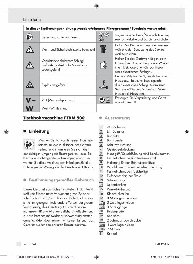
36 DE/AT
Tischbohrmaschine PTBM 500
Q Einleitung
Machen Sie sich vor der ersten Inbetrieb- nahme mit den Funktionen des Gerätes vertraut und informieren Sie sich über
den richtigen Umgang mit Elektrogeräten. Lesen Sie hierzu die nachfolgende Bedienungsanleitung. Be-wahren Sie diese Anleitung auf. Händigen Sie alle Unterlagen bei Weitergabe des Gerätes an Dritte aus.
Q Bestimmungsgemäßer Gebrauch
Dieses Gerät ist zum Bohren in Metall, Holz, Kunst-stoff und Fliesen unter Verwendung von Zylinder-schaftbohrern ø 1,5 mm bis max. Bohrdurchmesser ø 16 mm geeignet. Jede andere Verwendung oder Veränderung des Gerätes gilt als nicht bestim-mungsgemäß und birgt erhebliche Unfallgefahren. Für aus bestimmungswidriger Verwendung entstan-dene Schäden übernehmen wir keine Haftung. Das Gerät ist nur für den privaten Einsatz bestimmt.
Q ausstattung
1 AUS-Schalter2 EIN-Schalter3 Bohrfutter4 Bohrspindel5 Schutzvorrichtung6 Getriebeabdeckung7 Handgriff / Spindelführung mit 3 Bohrhubarmen8 Feststellschraube Bohrtiefenvorwahl9 Halterung für den Bohrfutterschlüssel
10 Verschlussschraube Getriebeabdeckung11 Feststellschrauben (beidseitig)12 Tiefenanschlag mit Skala13 Schraubstock14 Spannbacken15 Winkelskalierung16 Klemmschraube17 3 Montageschrauben17 a 3 Unterlegscheiben17 b 3 Sprengringe18 Bodenplatte19 Bohrtisch20 2 Schraubstockschrauben20 a 4 Unterlegscheiben20 b 2 Muttern21 Knebel
In dieser Bedienungsanleitung werden folgende Piktogramme / Symbole verwendet:
Bedienungsanleitung lesen!Tragen Sie eine Atem- / Staubschutzmaske, eine Schutzbrille und Schutzhandschuhe.
Warn- und Sicherheitshinweise beachten!Halten Sie Kinder und andere Personen während der Benutzung des Elektro-werkzeugs fern.
Vorsicht vor elektrischem Schlag! Gefährliche elektrische Spannung – Lebensgefahr!
Halten Sie das Gerät von Regen oder Nässe fern. Das Eindringen von Wasser in ein Elektrogerät erhöht das Risiko eines elektrischen Schlages.
Explosionsgefahr!
Ein beschädigtes Gerät, Netzkabel oder Netzstecker bedeuten Lebensgefahr durch elektrischen Schlag. Kontrollieren Sie regelmäßig den Zustand von Gerät, Netzkabel, Netzstecker.
V~ Volt (Wechselspannung)Entsorgen Sie Verpackung und Gerät umweltgerecht!
W Watt (Wirkleistung)
Einleitung
E-3470_Table_Drill_PTBM500_Content_LB5.indd 36 17.03.2008 16:23:05 Uhr
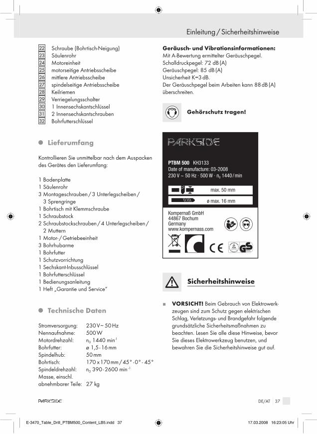
37 DE/AT
22 Schraube (Bohrtisch-Neigung)23 Säulenrohr24 Motoreinheit25 motorseitige Antriebsscheibe26 mittlere Antriebsscheibe27 spindelseitige Antriebsscheibe28 Keilriemen29 Verriegelungsschalter30 1 Innensechskantschlüssel 31 2 Innensechskantschrauben32 Bohrfutterschlüssel
Q Lieferumfang
Kontrollieren Sie unmittelbar nach dem Auspacken des Gerätes den Lieferumfang:
1 Bodenplatte1 Säulenrohr3 Montageschrauben / 3 Unterlegscheiben /
3 Sprengringe1 Bohrtisch mit Klemmschraube1 Schraubstock2 Schraubstockschrauben / 4 Unterlegscheiben /
2 Muttern1 Motor- / Getriebeeinheit3 Bohrhubarme1 Bohrfutter1 Schutzvorrichtung1 Sechskant-Inbusschlüssel1 Bohrfutterschlüssel1 Bedienungsanleitung1 Heft „Garantie und Service“
Q Technische Daten
Stromversorgung: 230 V~ 50 HzNennaufnahme: 500 WMotordrehzahl: n0 1440 min-1
Bohrfutter: ø 1,5 - 16 mmSpindelhub: 50 mmBohrtisch: 170 x 170 mm / 45° - 0° - 45°Spindeldrehzahl: n0 390 - 2600 min -1
Masse, einschl. abnehmbarer Teile: 27 kg
Geräusch- und Vibrationsinformationen:Mit A-Bewertung ermittelter Geräuschpegel.Schalldruckpegel: 72 dB (A)Geräuschpegel: 85 dB (A)Unsicherheit K=3 dB. Der Geräuschpegel beim Arbeiten kann 88 dB (A) überschreiten.
Gehörschutz tragen!
PTBM 500 KH3133Date of manufacture: 03-2008230 V ~ 50 Hz · 500 W · n0 1440 / min
Kompernaß GmbH 44867 Bochum Germany� www.kompernass.com
max. 50 mm
ø max. 16 mm
ID :00 0 0 0 21765
Sicherheitshinweise
J VOrSICHT! Beim Gebrauch von Elektrowerk-zeugen sind zum Schutz gegen elektrischen Schlag, Verletzungs- und Brandgefahr folgende grundsätzliche Sicherheitsmaßnahmen zu beachten. Lesen Sie alle diese Hinweise, bevor Sie dieses Elektrowerkzeug benutzen, und bewahren Sie die Sicherheitshinweise gut auf.
Einleitung / Sicherheitshinweise
E-3470_Table_Drill_PTBM500_Content_LB5.indd 37 17.03.2008 16:23:05 Uhr
38 DE/AT
Q Sicheres arbeiten
1. Halten Sie Ihren arbeitsbereich in Ordnung.
J Unordnung im Arbeitsbereich kann Unfälle zur Folge haben.
2. Berücksichtigen Sie Umgebungsein-flüsse.
J Setzen Sie Elektrowerkzeuge nicht dem Regen aus.
J Benutzen Sie Elektrowerkzeuge nicht in feuchter oder nasser Umgebung.
J Sorgen Sie für gute Beleuchtung des Arbeits-bereichs.
J Benutzen Sie Elektrowerkzeuge nicht, wo Brand- oder Explosionsge-fahr besteht.
3. Schützen Sie sich vor elek-trischem Schlag.
J Vermeiden Sie Körperberührung mit geerdeten Teilen (z.B. Rohre, Radiatoren, Elektroherde, Kühlgeräte).
4. Halten Sie andere Personen fern.J Lassen Sie andere Personen, insbe-
sondere Kinder, nicht das Elektro-werkzeug oder das Kabel berühren.
Halten Sie sie von Ihrem Arbeitsbereich fern. 5. Bewahren Sie unbenutzte Elektro-
werkzeuge sicher auf.J Unbenutzte Elektrowerkzeuge sollten an einem
trockenen, hochgelegenen oder abgeschlos-senen Ort, außerhalb der Reichweite von Kindern, abgelegt werden.
6. Überlasten Sie ihr Elektrowerkzeug nicht.
J Sie arbeiten besser und sicherer im angege-benen Leistungsbereich.
7. Benutzen Sie das richtige Elektro-werkzeug.
J Verwenden Sie keine leistungsschwachen Maschinen für schwere Arbeiten.
J Benutzen Sie das Elektrowerkzeug nicht für solche Zwecke, für die es nicht vorgesehen ist. Benutzen Sie zum Beispiel keine Handkreissäge zum Schneiden von Baumästen oder Holz-scheiten.
8. Tragen Sie geeignete Kleidung.J Tragen Sie keine weite Kleidung oder
Schmuck, sie könnten von beweglichen Teilen erfasst werden.
J Beim Arbeiten im Freien ist rutschfestes Schuh-werk empfehlenswert.
J Tragen Sie bei langen Haaren ein Haarnetz. 9. Benutzen Sie Schutzaus-
rüstung.J Tragen Sie eine Schutzbrille.J Verwenden Sie bei stauberzeugenden Arbeiten
eine Staubmaske.10. Verwenden Sie das Kabel
nicht für Zwecke, für die es nicht bestimmt ist.
J Benutzen Sie das Kabel nicht, um den Stecker aus der Steckdose zu ziehen. Schützen Sie das Kabel vor Hitze, Öl und scharfen Kanten.
11. Sichern Sie das Werkstück.J Benutzen Sie Spannvorrichtungen oder einen
Schraubstock, um das Werkstück festzuhalten. Es ist damit sicherer gehalten, als mit Ihrer Hand.
12. Vermeiden Sie abnorme Körperhal-tung.
J Sorgen Sie für sicheren Stand und halten Sie jederzeit das Gleichgewicht.
13. Pflegen Sie Ihre Werkzeuge mit Sorgfalt.
J Halten Sie die Schneidwerkzeuge scharf und sauber, um besser und sicherer arbeiten zu können.
J Befolgen Sie die Hinweise zur Schmierung und zum Werkzeugwechsel.
J Kontrollieren Sie regelmäßig die Anschlusslei-tung des Elektrowerkzeugs und lassen Sie diese bei Beschädigung von einem anerkannten Fachmann erneuern.
J Kontrollieren Sie Verlängerungsleitungen regelmäßig und ersetzen Sie diese, wenn sie beschädigt sind.
J Halten Sie Handgriffe trocken, sauber und frei von Öl und Fett.
14. Ziehen Sie den Stecker aus der Steckdose:
J Bei Nichtgebrauch des Elektrowerkzeugs, vor der Wartung und beim Wechsel von Werkzeu-gen wie z.B. Sägeblatt, Bohrer, Fräser.
Sicherheitshinweise
E-3470_Table_Drill_PTBM500_Content_LB5.indd 38 17.03.2008 16:23:05 Uhr
39 DE/AT
15. Lassen Sie keine Werkzeugschlüssel stecken.
J Überprüfen Sie vor dem Einschalten, dass Schlüssel und Einstellwerkzeuge entfernt sind.
16. Vermeiden Sie unbeaufsichtigten anlauf.
J Vergewissern Sie sich, dass der Schalter beim Einstecken des Steckers in die Steckdose aus-geschaltet ist.
17. Benutzen Sie Verlängerungskabel für den außenbereich.
J Verwenden Sie im Freien nur dafür zugelassene und entsprechend gekennzeichnete Verlänge-rungskabel.
18. Seien Sie aufmerksam.J Achten Sie darauf, was Sie tun. Gehen Sie mit
Vernunft an die Arbeit. Benutzen Sie das Elek-trowerkzeug nicht, wenn Sie unkonzentriert sind.
19. Überprüfen Sie das Elektrowerkzeug auf eventuelle Beschädigungen.
J Vor weiterem Gebrauch des Elektrowerkzeugs müssen Schutzvorrichtungen oder leicht be-schädigte Teile sorgfältig auf ihre einwandfreie und bestimmungsgemäße Funktion untersucht werden.
J Überprüfen Sie, ob die beweglichen Teile einwandfrei funktionieren und nicht klemmen, oder ob Teile beschädigt sind. Sämtliche Teile müssen richtig montiert sein und alle Beding-ungen erfüllen, um den einwandfreien Betrieb des Elektrowerkzeugs zu gewährleisten.
J Beschädigte Schutzvorrichtungen und Teile müssen bestimmungsgemäß durch eine anerkannte Fachwerkstatt repariert oder aus-gewechselt werden, soweit nichts anderes in der Gebrauchsanweisung angegeben ist.
J Beschädigte Schalter müssen bei einer Kundendienstwerkstatt ersetzt werden.
J Benutzen Sie keine Elektrowerkzeuge, bei denen sich der Schalter nicht ein- und aus-schalten lässt.
20. VOrSICHT!J Der Gebrauch anderer Einsatzwerkzeuge und
anderen Zubehörs kann eine Verletzungsgefahr für Sie bedeuten.
21. Lassen Sie Ihr Elektrowerkzeug durch eine Elektrofachkraft reparieren.
J Dieses Elektrowerkzeug entspricht den ein-schlägigen Sicherheitsbestimmungen. Repara-turen dürfen nur von einer Elektrofachkraft ausgeführt werden, indem Originalersatzteile verwendet werden; andernfalls können Unfälle für den Benutzer entstehen.
Gerätespezifische Sicherheitshinweise für Tischbohrmaschinen
J VOrSICHT: Zu hoher Anpressdruck überlastet den Motor und verringert die Drehzahl.
J Benutzen Sie nur geschärfte Werkzeuge.J Kühlen Sie den Bohrer mit einer geeigneten
Flüssigkeit.J Für Bohrungen in Edelstahl benötigen Sie
spezielle Bohrer.J Kontrollieren Sie vor jeder Benutzung den festen
Sitz des Bohrfutters 3 , des Bohrtisches 19 und der Verschraubungen.
J Prüfen Sie die Funktion des Verriegelungs- schalters 29 unter der Getriebeabdeckung 6 : Die Tischbohrmaschine muss sich beim Öffnen der Getriebeabdeckung 6 ausschalten.
J Entfernen Sie Späne nie mit der Hand. Andernfalls droht Verletzungsgefahr.
J Tragen Sie bei der Arbeit keine Handschuhe, ansonsten droht Verwicklungsgefahr.
J WarnUnG! Beachten Sie, dass die Berüh- rung oder das Einatmen von Stäuben eine Ge-fährdung für die das Gerät bedienende Person oder in der Nähe befindliche Personen darstel-len kann. Halten Sie in Bezug auf Stäube alle geeigneten Schutzmaßnahmen ein.
J WarnUnG! Halten Sie Ihren Arbeitsplatz sauber. Materialmischungen sind besonders gefährlich. Leichtmetallstaub z.B. kann brennen oder explodieren.WarnUnG! STrOMSCHLaGGEFaHr
DUrCH METaLLSTaUB! Bei Bearbeitung von Metall kann sich ein leit-fähiger Staub im Inneren des Gerätes absetzen. Betreiben Sie das Gerät über einen FI - Schutzschalter (Aus-lösestrom 30 mA).
J Asbesthaltiges Material darf nicht bearbeitet werden. Asbest gilt als krebserregend.
Sicherheitshinweise
E-3470_Table_Drill_PTBM500_Content_LB5.indd 39 17.03.2008 16:23:06 Uhr
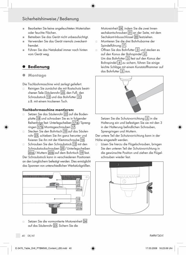
40 DE/AT
J Bearbeiten Sie keine angefeuchteten Materialien oder feuchte Flächen.
J Betreiben Sie das Gerät nicht unbeaufsichtigt.J Verwenden Sie das Gerät niemals zweckent-
fremdet.J Führen Sie das Netzkabel immer nach hinten
vom Gerät weg.
Q Bedienung
Q Montage
Die Tischbohrmaschine wird zerlegt geliefert.j Reinigen Sie zunächst die mit Rostschutz bestri-
chenen Teile (Säulenrohr 23, den Fuß, den Schraubstock 13 und das Bohrfutter 3 ) z.B. mit einem trockenen Tuch.
Tischbohrmaschine montieren:j Setzen Sie das Säulenrohr 23 auf die Boden-
platte 18 und schrauben Sie es in folgender Reihenfolge fest: Unterlegscheiben 17 a / Spreng- ringen 17 b Montageschrauben 17.
j Stecken Sie den Bohrtisch 19 auf das Säulen-rohr 23 , schieben Sie ihn ganz herunter und fixieren Sie ihn mit der Klemmschraube 16.
j Schrauben Sie den Schraubstock 13 mit den Schraubstockschrauben 20 / Unterlegscheiben 20 a / Muttern 20 b auf dem Bohrtisch 19 fest.
Der Schraubstock kann in verschiedenen Positionen an den Langlöchern befestigt werden. Dies ermöglicht das Spannen von unterschiedlichen Werkstückgrößen.
2013
19
20 b20 a
20 a
j Setzen Sie die vormontierte Motoreinheit 24 auf das Säulenrohr 23. Sichern Sie die
Motoreinheit 24 , indem Sie die zwei Innen- sechskantschrauben 31 an der Seite, mit dem Sechskant-Inbusschlüssel 30 festziehen.
j Montieren Sie die drei Bohrhubarme der Spindelführung 7 .
j Öffnen Sie das Bohrfutter 3 und stecken es auf den Konus der Bohrspindel 4 . Um das Bohrfutter 3 fest auf den Konus der Bohrspindel 4 zu sichern, führen Sie einige leichte Schläge mit einem Kunststoffhammer auf das Bohrfutter 3 aus.
Setzen Sie die Schutzvorrichtung 5 in die Halterung ein und befestigen Sie sie mit den 3 in der Halterung befindlichen Schrauben, Sprengringen und Muttern.
Der untere Teil der Schutzvorrichtung kann in der Höhe eingestellt werden. j Lösen Sie hierzu die Flügelschrauben, bringen
Sie den unteren Teil der Schutzvorrichtung in die gewünschte Position und ziehen die Flügel-schrauben wieder fest.
Sicherheitshinweise / Bedienung
E-3470_Table_Drill_PTBM500_Content_LB5.indd 40 17.03.2008 16:23:06 Uhr
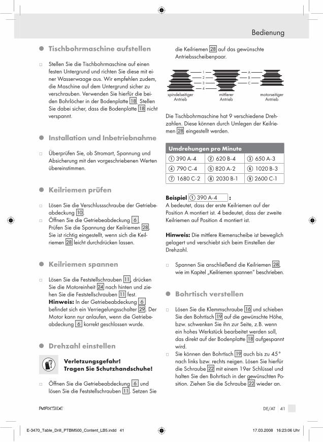
41 DE/AT
Q Tischbohrmaschine aufstellen
j Stellen Sie die Tischbohrmaschine auf einen festen Untergrund und richten Sie diese mit ei-ner Wasserwaage aus. Wir empfehlen zudem, die Maschine auf dem Untergrund sicher zu verschrauben. Verwenden Sie hierfür die bei-den Bohrlöcher in der Bodenplatte 18. Stellen Sie dabei sicher, dass die Bodenplatte 18 nicht verspannt.
Q Installation und Inbetriebnahme
j Überprüfen Sie, ob Stromart, Spannung und Absicherung mit den vorgeschriebenen Werten übereinstimmen.
Q Keilriemen prüfen
j Lösen Sie die Verschlussschraube der Getriebe-abdeckung 10.
j Öffnen Sie die Getriebeabdeckung 6 . Prüfen Sie die Spannung der Keilriemen 28.
Sie ist richtig eingestellt, wenn sich die Keil- riemen 28 leicht durchdrücken lassen.
Q Keilriemen spannen
j Lösen Sie die Feststellschrauben 11, drücken Sie die Motoreinheit 24 nach hinten und zie-hen Sie die Feststellschrauben 11 fest.
Hinweis: In der Getriebeabdeckung 6 befindet sich ein Verriegelungsschalter 29 . Der Motor kann nur anlaufen, wenn die Getriebe-abdeckung 6 korrekt geschlossen wurde.
Q Drehzahl einstellen
Verletzungsgefahr! Tragen Sie Schutzhandschuhe!
j Öffnen Sie die Getriebeabdeckung 6 und lösen Sie die Feststellschrauben 11. Setzen Sie
die Keilriemen 28 auf das gewünschte Antriebsscheibenpaar.
ABC
1
2
3
4
spindelseitiger Antrieb
mittlerer Antrieb
motorseitiger Antrieb
Die Tischbohrmaschine hat 9 verschiedene Dreh-zahlen. Diese können durch Umlegen der Keilrie-men 28 eingestellt werden.
Umdrehungen pro Minute
Q 390 A - 4 W 620 B - 4 E 650 A - 3
R 790 C - 4 T 820 A - 2 Y 1020 B - 3
U 1680 C - 2 I 2030 B - 1 O 2600 C - 1
Beispiel Q 390 A - 4 : A bedeutet, dass der erste Keilriemen auf der Position A montiert ist. 4 bedeutet, dass der zweite Keilriemen auf Position 4 montiert ist.
Hinweis: Die mittlere Riemenscheibe ist beweglich gelagert und verschiebt sich beim Einstellen der Drehzahl.
j Spannen Sie anschließend die Keilriemen 28, wie im Kapitel „Keilriemen spannen“ beschrieben.
Q Bohrtisch verstellen
j Lösen Sie die Klemmschraube 16 und schieben Sie den Bohrtisch 19 auf die gewünschte Höhe, bzw. schwenken Sie ihn zur Seite, z.B. wenn ein hohes Werkstück bearbeitet werden soll, das direkt auf der Bodenplatte 18 aufgespannt wird.
j Sie können den Bohrtisch 19 auch bis zu 45° nach links bzw. rechts neigen. Lösen Sie hierfür die Schraube 22 mit einem 19er Schlüssel und halten Sie den Bohrtisch in der gewünschten Po-sition. Ziehen Sie die Schraube 22 wieder an.
Bedienung
E-3470_Table_Drill_PTBM500_Content_LB5.indd 41 17.03.2008 16:23:06 Uhr

42 DE/AT
Q Bohrtiefe vorwählen
Der Tiefenanschlag mit Skala 12 ermöglicht eine Vorwahl der Bohrtiefe. j Lösen Sie die Klemmschraube 16 des Bohr-
tisches 19. Verschieben Sie den Bohrtisch 19 bis das eingespannte Werkstück an der Bohrer-spitze anliegt.
Stellen Sie die Bohrtiefe wie folgt ein.j Lösen Sie die Feststellschraube 8 .j Drehen Sie die Skala 12 der Bohrtiefenvor-
wahl bis die gewünschte Bohrtiefe an der Pfeil-markierung anliegt.
j Stellen Sie die Feststellschraube 8 fest.
Hinweis: Die linke Seite der Skala 12 zeigt die Bohrtiefe. Die rechte Seite der Skala 12 zeigt den verbleibenden Bohrhub.
Q Werkzeugwechsel / Bohrer einspannen
WarnUnG! Bevor Sie Arbeiten am Gerät durchführen, ziehen Sie immer den Netzstecker aus der Steckdose. Dies verhindert den unbeabsichtigten Start des Gerätes. j Klappen Sie die Schutzvorrichtung 5 hoch.j Lösen Sie die Haltebacken des Bohrfutters 3
mit dem Bohrfutterschlüssel 32 .j Entnehmen Sie das Werkzeug.j Setzen Sie den Bohrer ein und spannen Sie die
Haltebacken des Bohrfutters 3 mit dem Bohr-futterschlüssel 32 .
Achten Sie darauf das der Bohrer zentriert in das Bohrfutter eingespannt ist.
Q Werkstück in Schraubstock einspannen
Zum Öffnen der Spannbacken 14 drehen Sie den Knebel 21 gegen den Uhrzeigersinn. Legen Sie das Werkstück zwischen die Spannbacken 14 und klemmen Sie dieses durch drehen des Knebels 21 im Uhrzeigersinn fest.
Hinweis: Der Schraubstock 13 dient zum Spannen von flachen und kantigen Werkstücken.Rohre sind nur bedingt spannbar.
Q Tischbohrmaschine ein- und ausschalten
Einschalten:j Drücken Sie den EIN-Schalter 2 .
ausschalten:j Drücken Sie den AUS-Schalter 1 .
Q Bohren
Drehen Sie den Handgriff 7 an einem der drei Bohrhubarme gegen den Uhrzeigersinn. Das Bohr-futter 3 senkt sich. Drehen Sie den Handgriff so weit, bis der Bohrer entsprechend der gewünschten Tiefe in das Werkstück eintaucht, siehe auch Abb. D.Führen Sie nach erfolgter Bohrung den Handgriff 7 wieder in entgegen gesetzter Richtung in die Aus-gangsstellung.
Hinweis: Beachten Sie, dass Handgriff über einen Gegendruck verfügt. Sollten Sie den Handgriff los-lassen, schnellt er zurück in die Ausgangsstellung.
Q Werkstoffe bearbeiten / Beispiele
Metall bearbeiten:j Wählen Sie für harte Metalle und / oder große
Bohrdurchmesser eine niedrige Drehzahl.
Holzwerkstoffe bearbeiten:j Verwenden Sie eine Staubschutzmaske,
Holzstäube sind gesundheitsschädlich.
Weitere anwendungsbeispieleKeramikfliesen / Kunststoffe bearbeiten: j Arbeiten Sie mit niedriger Drehzahl.
Verwenden Sie einen geeigneten Bohrer mit Zentrierspitze.
Bedienung
E-3470_Table_Drill_PTBM500_Content_LB5.indd 42 17.03.2008 16:23:07 Uhr

43 DE/AT
Q Wartung und reinigung
WarnUnG! Bevor Sie Arbeiten am Gerät durchführen, ziehen Sie immer den Netzstecker aus der Steckdose. Dies verhindert den unbeabsich-tigten Start des Gerätes.
j Reinigen Sie das Gerät regelmäßig, direkt nach Abschluss der Arbeit.
j Verwenden Sie zur Reinigung des Gehäuses ein trockenes Tuch und keinesfalls Benzin, Lösungsmittel oder Reiniger.
j Entfernen Sie Späne, Staub und Schmutz ggf. mit einem Staubsauger.
j Schmieren Sie bewegliche Teile regelmäßig.j Stellen Sie sicher, dass keine Schmierstoffe auf
Schalter 1 , 2 , Keilriemen 28 und Antriebs-scheiben 25, 26 , 27 gelangen.
Q Entsorgung
Die Verpackung besteht aus umwelt-freundlichen Materialien, die Sie über die örtlichen Recyclingstellen entsorgen können.
Werfen Sie Elektrowerkzeuge nicht in den Hausmüll!
Gemäß Europäischer Richtlinie 2002 / 96 / EG über Elektro- und Elektronik-Altgeräte und Umsetzung in nationales Recht müssen verbrauchte Elektro-werkzeuge getrennt gesammelt und einer umwelt-gerechten Wiederverwertung zugeführt werden.
Möglichkeiten zur Entsorgung des ausgedienten Gerätes erfahren Sie bei Ihrer Gemeinde- oder Stadtverwaltung.
Q Informationen
Q Service
Die zuständige Servicestelle Ihres Landes entnehmen Sie bitte den Garantieunterlagen.
J Lassen Sie Ihr Gerät nur von qualifi-ziertem Fachpersonal und nur mit Originalersatzteilen reparieren. Damit wird sichergestellt, dass die Sicherheit des Gerätes erhalten bleibt.
J Lassen Sie den austausch des netz-steckers oder der anschlussleitung immer vom Hersteller des Elektro-werkzeugs oder seinem Kundendienst ausführen. Damit wird sichergestellt, dass die Sicherheit des Gerätes erhalten bleibt.
Wartung und Reinigung / Entsorgung / Informationen
E-3470_Table_Drill_PTBM500_Content_LB5.indd 43 17.03.2008 16:23:07 Uhr

44 DE/AT
Q Konformitätserklärung / Hersteller
Wir, Kompernaß GmbH, Burgstr. 21, 44867 Bochum, Deutschland, erklären hiermit für dieses Produkt die Übereinstimmung mit den geltenden EG-Normen und bestätigen dies durch CE-Kennzeichnung.
Maschinenrichtlinie (98 / 37 / EG)
EG-niederspannungsrichtlinie (2006 / 95 / EG)Geprüft nach Tested acc.toEN 61029 - 1: 2000 + A11 + A12
Elektromagnetische Verträglichkeit (2004 / 108 / EG)Geprüft nach Tested acc.toEN 55014 - 1: 2000 + A1 + A2EN 55014 - 2: 1997 + A1EN 61000 - 3 - 2: 2000 + A2EN 61000 - 3 - 3: 1995 + A1
Typ / Gerätebezeichnung:Parkside Tischbohrmaschine PTBM 500
Bochum, 31.03.2008
Hans Kompernaß- Geschäftsführer -
Technische Änderungen im Sinne der Weiterentwicklung sind vorbehalten.
Informationen
E-3470_Table_Drill_PTBM500_Content_LB5.indd 44 17.03.2008 16:23:07 Uhr