DCTC4: CELLA DI CARICO CON INDICATORE LOAD CELL … · risultati delle prove e delle valutazioni...
26
DCTC4: CELLA DI CARICO CON INDICATORE LOAD CELL WITH INDICATOR MANUALE OPERATIVO OPERATING MANUAL MO.DCTC4.326.R4 Box 79 Hantverksvägen 15 Tel. +46 (0)176-208920 Web www.vetek.se 76040 Väddö, Sverige Fax +46 (0)176-208929 Email [email protected]
Transcript of DCTC4: CELLA DI CARICO CON INDICATORE LOAD CELL … · risultati delle prove e delle valutazioni...
DCTC4: CELLA DI CARICO CON INDICATORE LOAD CELL WITH INDICATOR
MANUALE OPERATIVO OPERATING MANUAL
MO.DCTC4.326.R4
Box 79 Hantverksvägen 15 Tel. +46 (0)176-208920 Web www.vetek.se 76040 Väddö, Sverige Fax +46 (0)176-208929 Email [email protected]
DCTC4 Manuale Operativo - Operating Manual MO.DCTC4.326.R4
DICHIARAZIONE DI CONFORMITA'
CONFORMITY DECLARATION
Costruttore: AEP transducers s.r.l. Indirizzo: via Bottego 33/A 41126 Cognento MODENA Italia DICHIARA CHE IL SEGUENTE PRODOTTO: Nome del prodotto: DCTC4 Tipo: Dinamometro Digitale
Opzioni: questa dichiarazione copre tutte le opzioni specificate nel catalogo di vendita.
E' CONFORME ALLE SEGUENTI NORME: EN 61010-1(2001) EN 61326-1(2007)
Il prodotto è stato provato nella configurazione tipica di installazione descritta nel manuale di istruzioni. Il prodotto soddisfa i requisiti delle Norme citate, sulla base dei risultati delle prove e delle valutazioni descritte nel Fascicolo Tecnico.
Io sottoscritto dichiaro che il prodotto soddisfa i requisiti delle Direttive 2004/108/CE - 2006/95/CE – 2011/65/UE - 2002/96/CE. 41126 Cognento MODENA 17/12/2012 Lioi Giovanni Direttore Tecnico
Manufacturer: AEP transducers s.r.l. address: via Bottego 33/A 41126 Cognento MODENA Italy DECLARES THAT THE FOLLOWING PRODUCT: Product name: DCTC4 Type: Digital Dynamometer
Options: this declaration covers all the options specified in the sales catalogue.
CONFORMS TO THE FOLLOWING NORMS: EN 61010-1(2001) EN 61326-1(2007)
The product has been tested in the typical installation configuration, as described in the instruction manual. Above described product meets the requirements of mentioned Norms, basing on both test results and considerations listed in the technical file.
I declare that the product defined above meets the requirements of the 2004/108/CE - 2006/95/CE -2011/65/EU - 2002/96/CE Directives. 41126 Cognento MODENA 17/12/2012 Lioi Giovanni Technical Manager
pag. 1

DCTC4 Manuale Operativo - Operating Manual MO.DCTC4.326.R4
INDICE GENERALE GENERAL INDEX Pag. INTRODUZIONE INTRODUCTION 3 DESCRIZIONE DI FUNZIONAMENTO FUNCTIONING DESCRIPTION 4 DATI TECNICI - Opzioni TECHNICAL DATA - Options 5 - 6 Trasporto, Consegna, Posizionamento, Installazione Transport, Delivery, Positioning, Installation 7 Accensione, Spegnimento, Manutenzione, Smaltimento Power-on, Power-off, Maintenance, Disposal 8 TASTIERA - Descrizione tasti - Indicazioni display KEYBOARD - Keys description - Display indications 9 - 11 MENU DI PROGRAMMAZIONE DEI PARAMETRI PARAMETERS PROGRAMMING MENU 11 - Password - Risoluzione di misura - Password - Measurement Resolution 12 - Filtro digitale - Picco - Digital Filter - Peak 13 - Comunicazione Seriale e protocollo di comunicazione - Serial communication and communication protocol 14 - Fondo Scala Positivo(Compressione) - Punto Decimale - Positive Full Scale(Compression) - Decimal Point 15 - Fondo Scala Negativo(Trazione) - Negative Full Scale(Tension) 16 FUNZIONE di ZERO - FUNZIONE di PICCO ZERO FUNCTION - PEAK FUNCTION 17 COMUNICAZIONE SERIALE - Comandi SERIAL OUTPUT - Commands 18 - Collegamenti uscita Seriale - Serial output connections 19 COLLEGAMENTI ELETTRICI ELECTRIC CONNECTIONS 20 DIMENSIONI del DINAMOMETRO DYNAMOMETER DIMENSIONS 20 - 21 APPLICAZIONI del DINAMOMETRO DYNAMOMETER APPLICATIONS 22 - Caratteristiche viti di fissaggio - Dimensioni con accessori - Fixing screws characteristics - Dimensions with accessories 23 - 24 MESSAGGI ERRORE - RICERCA GUASTI ERROR MESSAGES - TROUBLE SHOOTING 25
pag. 2
DCTC4 Manuale Operativo - Operating Manual MO.DCTC4.326.R4
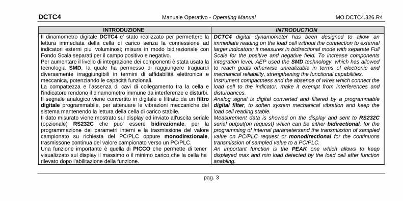
INTRODUZIONE INTRODUCTION Il dinamometro digitale DCTC4 e' stato realizzato per permettere la lettura immediata della cella di carico senza la connessione ad indicatori esterni piu' voluminosi; misura in modo bidirezionale con Fondo Scala separati per il campo positivo e negativo. Per aumentare il livello di integrazione dei componenti è stata usata la tecnologia SMD, la quale ha permesso di raggiungere traguardi diversamente irraggiungibili in termini di affidabilità elettronica e meccanica, potenziando le capacità funzionali. La compattezza e l'assenza di cavi di collegamento tra la cella e l'indicatore rendono il dinamometro immune da interferenze e disturbi. Il segnale analogico viene convertito in digitale e filtrato da un filtro digitale programmabile, per attenuare le vibrazioni meccaniche del sistema mantenendo la lettura della cella di carico stabile. Il dato misurato viene mostrato sul display ed inviato all'uscita seriale (opzionale) RS232C che puo' essere bidirezionale, per la programmazione dei parametri interni e la trasmissione del valore campionato su richiesta del PC/PLC oppure monodirezionale, trasmissone continua del valore campionato verso un PC/PLC. Una funzione importante è quella di PICCO che permette di tener visualizzato sul display il massimo o il minimo carico che la cella ha rilevato dopo l'abilitazione della funzione.
DCTC4 digital dynamometer has been designed to allow an immediate reading on the load cell without the connection to external larger indicators; it measures in bidirectional mode with separate Full Scale for the positive and negative field. To increase components integration level, AEP used the SMD technology, which has allowed to reach goals otherwise unrealizable in terms of electronic and mechanical reliability, strengthening the functional capabilities. Instrument compactness and the absence of wires which connect the load cell to the indicator, make it exempt from interferences and disturbances. Analog signal is digital converted and filtered by a programmable digital filter, to soften system mechanical vibration and keep the load cell reading stable. Measurement data is showed on the display and sent to RS232C serial output(on request) which can be either bidirectional, for the programming of internal parametersand the transmission of sampled value on PC/PLC request or monodirectional for the continuons transmission of sampled value to a PC/PLC. An important function is the PEAK one which allows to keep displayed max and min load detected by the load cell after function anabling.
pag. 3
DCTC4 Manuale Operativo - Operating Manual MO.DCTC4.326.R4
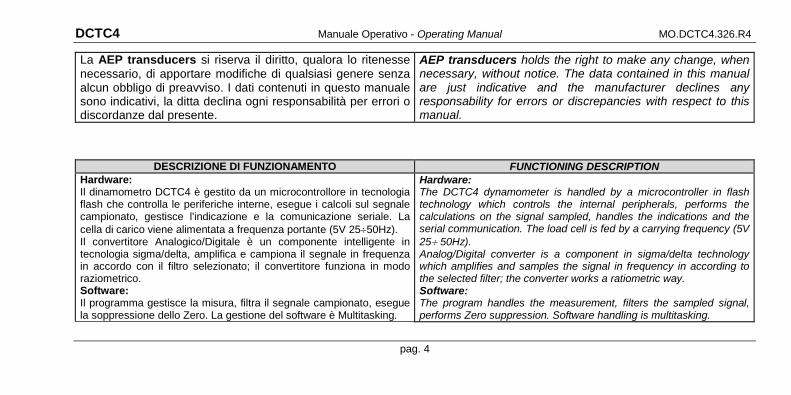
La AEP transducers si riserva il diritto, qualora lo ritenesse necessario, di apportare modifiche di qualsiasi genere senza alcun obbligo di preavviso. I dati contenuti in questo manuale sono indicativi, la ditta declina ogni responsabilità per errori o discordanze dal presente.
AEP transducers holds the right to make any change, when necessary, without notice. The data contained in this manual are just indicative and the manufacturer declines any responsability for errors or discrepancies with respect to this manual.
DESCRIZIONE DI FUNZIONAMENTO FUNCTIONING DESCRIPTION Hardware: Il dinamometro DCTC4 è gestito da un microcontrollore in tecnologia flash che controlla le periferiche interne, esegue i calcoli sul segnale campionato, gestisce l'indicazione e la comunicazione seriale. La cella di carico viene alimentata a frequenza portante (5V 25÷50Hz). Il convertitore Analogico/Digitale è un componente intelligente in tecnologia sigma/delta, amplifica e campiona il segnale in frequenza in accordo con il filtro selezionato; il convertitore funziona in modo raziometrico. Software: Il programma gestisce la misura, filtra il segnale campionato, esegue la soppressione dello Zero. La gestione del software è Multitasking.
Hardware: The DCTC4 dynamometer is handled by a microcontroller in flash technology which controls the internal peripherals, performs the calculations on the signal sampled, handles the indications and the serial communication. The load cell is fed by a carrying frequency (5V 25÷ 50Hz). Analog/Digital converter is a component in sigma/delta technology which amplifies and samples the signal in frequency in according to the selected filter; the converter works a ratiometric way. Software: The program handles the measurement, filters the sampled signal, performs Zero suppression. Software handling is multitasking.
pag. 4
DCTC4 Manuale Operativo - Operating Manual MO.DCTC4.326.R4
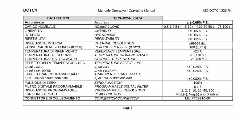
DATI TECNICI TECHNICAL DATA Accuratezza Accuracy ≤ ± 0.05% F.S. CARICO NOMINALE NOMINAL LOAD 0.5-1-2.5 t 5-10 t 20-30-50 t 75-100 t LINEARITA’ ISTERESI RIPETIBILITA'
LINEARITY HYSTERESIS REPEATABILITY
≤±0.05% F.S. ≤±0.05% F.S. ≤±0.02% F.S.
RISOLUZIONE INTERNA CONVERSIONI AL SECONDO (filtro 0)
INTERNAL RESOLUTION READINGS PER SEC. (0 filter)
±99999 div. 100 (10ms)
TEMPERATURA DI RIFERIMENTO TEMPERATURA DI ESERCIZIO TEMPERATURA DI STOCCAGGIO
REFERENCE TEMPERATURE TEMPERATURE WORKING RANGE STORAGE TEMPERATURE
+23°C -10/+70 °C -20/+80 °C
EFFETTO DELLA TEMPERATURA 10°C a) sullo zero b) sulla sensibilità EFFETTO CARICO TRASVERSALE: a) al 10% del carico nominale
TEMPERATURE EFFECT 10°C a) on zero b) on sensitivity TRANSVERSE LOAD EFFECT: a) at 10% of nominal load
≤±0.028% F.S. ≤±0.024% F.S.
≤±0.030% F.S.
FUNZIONE DI ZERO FILTRO DIGITALE PROGRAMMABILE RISOLUZIONE PROGRAMMABILE FUNZIONE DI PICCO
ZERO FUNCTION PROGRAMMABLE DIGITAL FILTER PROGRAMMABLE RESOLUTION PEAK FUNCTION
100% 0 ÷ 5
1, 2, 5, 10, 20, 50, 100 Pos.(+), Neg.(-) and Disabled
CONNETTORE DI COLLEGAMENTO CONNECTION CONNECTOR MIL PT02E10-6P
pag. 5
DCTC4 Manuale Operativo - Operating Manual MO.DCTC4.326.R4
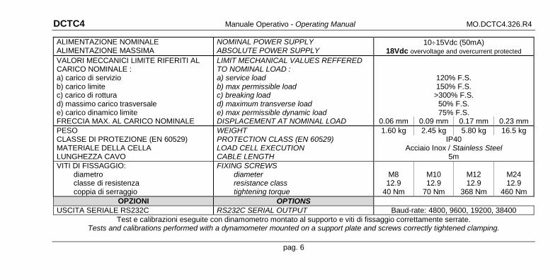
ALIMENTAZIONE NOMINALE ALIMENTAZIONE MASSIMA
NOMINAL POWER SUPPLY ABSOLUTE POWER SUPPLY
10÷15Vdc (50mA) 18Vdc overvoltage and overcurrent protected
VALORI MECCANICI LIMITE RIFERITI AL CARICO NOMINALE : a) carico di servizio b) carico limite c) carico di rottura d) massimo carico trasversale e) carico dinamico limite
LIMIT MECHANICAL VALUES REFFERED TO NOMINAL LOAD : a) service load b) max permissible load c) breaking load d) maximum transverse load e) max permissible dynamic load
120% F.S. 150% F.S.
>300% F.S. 50% F.S. 75% F.S.
FRECCIA MAX. AL CARICO NOMINALE DISPLACEMENT AT NOMINAL LOAD 0.06 mm 0.09 mm 0.17 mm 0.23 mm PESO WEIGHT 1.60 kg 2.45 kg 5.80 kg 16.5 kg CLASSE DI PROTEZIONE (EN 60529) MATERIALE DELLA CELLA LUNGHEZZA CAVO
PROTECTION CLASS (EN 60529) LOAD CELL EXECUTION CABLE LENGTH
IP40 Acciaio Inox / Stainless Steel
5m VITI DI FISSAGGIO:
diametro classe di resistenza coppia di serraggio
FIXING SCREWS diameter resistance class tightening torque
M8 12.9
40 Nm
M10 12.9
70 Nm
M12 12.9
368 Nm
M24 12.9
460 Nm OPZIONI OPTIONS
USCITA SERIALE RS232C RS232C SERIAL OUTPUT Baud-rate: 4800, 9600, 19200, 38400 Test e calibrazioni eseguite con dinamometro montato al supporto e viti di fissaggio correttamente serrate.
Tests and calibrations performed with a dynamometer mounted on a support plate and screws correctly tightened clamping.
pag. 6

DCTC4 Manuale Operativo - Operating Manual MO.DCTC4.326.R4
TRASPORTO TRANSPORT La componentistica é elettronica. In caso di trasporto imballare adeguatamente lo strumento. Attenzione ai forti urti e all’umidità.
The device is made of electronic components. In case of transport pack it carefully. Pay attention to both strong shocks and humidity.
CONSEGNA DELIVERY Il dinamometro viene consegnato collaudato in ogni particolare, configurato e calibrato.
The dynamometer is tested in any of its parts, it is supplied configurated and calibrated.
POSIZIONAMENTO POSITIONING Il dinamometro deve essere fissato alla struttura con le viti di fissaggio correttamente serrate. Posizionare in luogo adeguatamente protetto dagli agenti atmosferici.
The dynamometer must be fixed to the structure with the fixing screws correctly shut. Position it in a properly protected agains atmospheric agents place.
INSTALLAZIONE INSTALLATION L'installazione deve essere eseguita da personale istruito. Il dinamometro è costruito in conformità alla Norma di prodotto EN61326-1, affinché sia rispettata la conformità è necessario eseguire i collegamenti elettrici seguendo le indicazioni riportate in questo manuale ed alle marcature presenti sul dinamometro. Normalmente la comunicazione seriale funziona anche con adattatori di protocollo, tuttavia la Ditta a causa dei diversi adattatori in commercio, non garantisce la piena funzionalità della comunicazione seriale quando sono collegati adattatori di protocollo, in questo caso, il personale che esegue l'installazione dovrà prendere le precauzioni necessarie a prevenire i possibili malfunzionamenti.
Installation shall be done by authorized personnel only. The dynamometer is manufactured according to the EN61326-1 Norm; in order to have the conformity respected it is necessary to perform the electrical connections according both to what written in this manual and to the markings present on the dynamometer. Commonly the serial communication also functions with protocol adapters, but the Firm because there are different adapters in commerce, it doesn't guarantee the full functional of the serial communication when protocol adapters are connected, in this case, the personnel that performs the installation will take the necessary heeds to arrive before the possible malfunctions..
pag. 7
DCTC4 Manuale Operativo - Operating Manual MO.DCTC4.326.R4
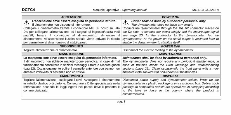
ACCENSIONE POWER ON
L'accensione deve essere eseguita da personale istruito. Il dinamometro non dispone di interruttore.
Power shall be done by authorized personnel only. The dynamometer does not have any switch.
Collegare il dinamometro tramite il connettore MIL 6P posto sul lato Dx; per collegare l'alimentazione ed i segnali di ingresso/uscita vedi pag.20; fissare il connettore al dinamometro; alimentare il dinamometro. All’accensione l'uscita seriale viene attivata in ritardo per permettere al dinamometro di stabilizzarsi.
Connect the dynamometer through the MIL 6P connector placed on the Dx side; to connect the power supply and the input/output signal see page 20; fix the connector to the dynamometer; fed the dynamometer. At the power on the serial output is activated later to enable the dynamometer to stabilize itself.
SPEGNIMENTO POWER OFF Togliere alimentazione al dinamometro. Disconnect the electric feeding to the dynamometer.
MANUTENZIONE MAINTENANCE La manutenzione deve essere eseguita da personale informato. Il dinamometro non richiede manutenzione periodica; in caso di mal funzionamento consultare le sezioni Messaggi Errore e Ricerca guasti (pag.22). Occasionalmente pulire il pannello anteriore con panno non abrasivo imbevuto di sostanze non corrosive.
Maintenance shall be done by authorized personnel only. The dynamometer daes not require any periodical maintenance; in case of troubles check the Error Message and troubleshouting sections (page 22). Clean occasionally the front panel with a non-abrasive cloth soaked with non-corrosive substrancies.
SMALTIMENTO DISPOSAL Togliere l'alimentazione; scollegare i cavi. Avvolgere il dinamometro in imballo plastico o di cartone. Consegnare a Ditte specializzate nella rottamazione secondo le leggi vigenti nel paese dove il prodotto è commercializzato.
Disconnect power supply and dynamometer cables. Wrap up the dynamometer in a plastic package or in a cardboard box. Deliver such package to companies swhich are specialized in scrapping according to the laws in force in the country where the product is commercialized.
pag. 8
DCTC4 Manuale Operativo - Operating Manual MO.DCTC4.326.R4
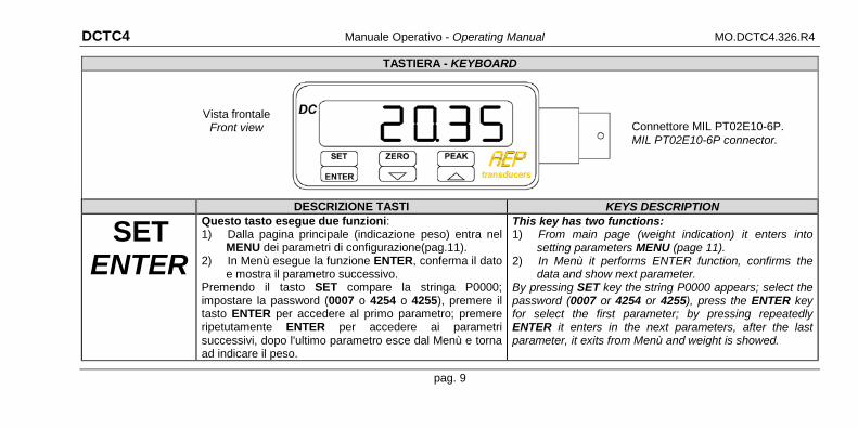
TASTIERA - KEYBOARD
DESCRIZIONE TASTI KEYS DESCRIPTION
SET ENTER
Questo tasto esegue due funzioni: 1) Dalla pagina principale (indicazione peso) entra nel
MENU dei parametri di configurazione(pag.11). 2) In Menù esegue la funzione ENTER, conferma il dato
e mostra il parametro successivo. Premendo il tasto SET compare la stringa P0000; impostare la password (0007 o 4254 o 4255), premere il tasto ENTER per accedere al primo parametro; premere ripetutamente ENTER per accedere ai parametri successivi, dopo l'ultimo parametro esce dal Menù e torna ad indicare il peso.
This key has two functions: 1) From main page (weight indication) it enters into
setting parameters MENU (page 11). 2) In Menù it performs ENTER function, confirms the
data and show next parameter. By pressing SET key the string P0000 appears; select the password (0007 or 4254 or 4255), press the ENTER key for select the first parameter; by pressing repeatedly ENTER it enters in the next parameters, after the last parameter, it exits from Menù and weight is showed.
Connettore MIL PT02E10-6P. MIL PT02E10-6P connector.
Vista frontale Front view
pag. 9

DCTC4 Manuale Operativo - Operating Manual MO.DCTC4.326.R4
ZERO
⇩
Questo tasto esegue due funzioni: 1) Nella pagina principale (indicazione peso) attiva o
disattiva la funzione di ZERO (pag.17). 2) In Menù decrementa il numero o cambia il
carattere sul display. Se tenuto premuto decrementa rapidamente il numero sul display.
Premendo il tasto ZERO per 3sec. si azzera il display; premendo il tasto ZERO per 6sec. la funzione di ZERO si disattiva.
This key has two functions: 1) In the main page (weight indication) it activates or
deactivates ZERO function (page 17). 2) In the Menù decreases the number or change the
character on the display. If kept pressed it rapidly decreases the number on the display.
By pressing ZERO key for 3sec. the display sets to zero; by pressing ZERO key for 6sec. ZERO function disables.
PEAK
⇧
Questo tasto esegue due funzioni: 1) Nella pagina principale (indicazione peso)
attiva/disattiva la funzione di Picco, quando la funzione è attiva il display lampeggia.
2) In Menù incrementa il numero o cambia il carattere sul display. Se tenuto premuto incrementa rapidamente il numero sul display.
Premendo il tasto PEAK si attiva/disattiva la funzione di Picco (pag.17), la funzione memorizza il valore massimo raggiunto in compressione o trazione.
This key has two functions: 1) In the main page (weight indication) it
activates/deactivates Peak function; when function is enabled, display flashes.
2) In the Menù increases the number or changes the character on the display. If keap pressed it rapidly increases the number on the display.
By pressing PEAK key peak function is either enabled or disabled (page 17), the function stores the max value reached either in compression or tension.
pag. 10

DCTC4 Manuale Operativo - Operating Manual MO.DCTC4.326.R4
INDICAZIONI DISPLAY DISPLAY INDICATIONS All’accensione il dinamometro indica la versione del software (fig.1); questa fase dura circa 3 secondi, quindi il dinamometro indica il peso ed è pronto a rispondere ai comandi dell’operatore. Nel caso si verifichi un funzionamento diverso da quello sopra descritto consultare Messaggi Errore e Ricerca Guasti (pag.22). L'indicazione della misura avviene per mezzo di 5 display rossi alti 13mm posti sul frontale dello strumento; i dati sono visualizzati in modo numerico, i messaggi con caratteri misti maiuscoli o minuscoli.
At its starting, dynamometer displays software version (picture 1). Such phase takes about 3 seconds then dynamometer shows the pressure and it is ready to perform operator instructions commands. If something, different form above described procedures happens, please go to Error Messages and Troubleshooting (page 22). Measurement display is performed through 5 red displays 13mm heigh placed on instrument front part. Data are displayed in a numeric way while messages use mixed characters (low and capital letters).
rel. 1.0
MENU di PROGRAMMAZIONE dei PARAMETRI PARAMETERS PROGRAMMING MENU Come accedere ai parametri del Menù: 1) Nella pagina del peso premere il tasto MENU, sul display
compare la stringa P0000. 2) Impostare la password. 3) Premere il tasto ENTER per accedere al primo parametro. 4) Per uscire dal MENU premere ripetutamente ENTER, dopo
l'ultimo parametro lo strumento torna ad indicare il peso
How to enter the Menù parameters: 1) In the weight page press MENU key, on the display the string
P0000 appears. 2) Selecting the password. 3) Press ENTER key to enter the first parameter. 4) To exit from the MENU press repeatedly ENTER, after last
parameter instrument shows back the weight
fig.1 esempio all'accensione pict.1 starting example
pag. 11

DCTC4 Manuale Operativo - Operating Manual MO.DCTC4.326.R4
PASSWORD PASSWORD Un numero di Password è richiesta per accedere ai seguenti Menù: 0007 Parametri protetti; 4254 Fondo Scala Positivo e Decimal Point; 4255 Fondo Scala Negativo.
A Password number is required to enter the following Manù: 0007 Protected parameters; 4254 Positive Full Scale and Decimal Point; 4255 Negative Full Scale.
P0000 Password Password
IMPOSTAZIONI PROTETTE DA PASSWORD 0007 SETTINGS PROTECTED BY PASSWORD 0007
RISOLUZIONE DI MISURA MEASUREMENT RESOLUTION Valori selezionabili: 1 2 5 10 20 50 100 Permette di definire l’incremento delle ultime cifre di una costante (1,2,5...). Questo sistema viene usato per aumentare la stabilità della misura in applicazioni dinamiche a scapito della precisione di lettura.
Selectable values: 1 2 5 10 20 50 100 This function enables the operator to define the increase of a constant last two digits (1,2,5...). This system is implemented to increase measurement stability in dynamic application at the expense of reading accuracy.
r 001 Risoluzione Resolution
pag. 12
DCTC4 Manuale Operativo - Operating Manual MO.DCTC4.326.R4
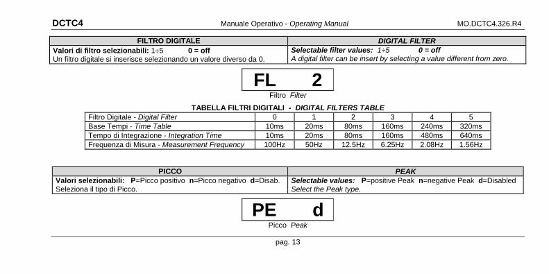
FILTRO DIGITALE DIGITAL FILTER Valori di filtro selezionabili: 1÷5 0 = off Un filtro digitale si inserisce selezionando un valore diverso da 0.
Selectable filter values: 1÷5 0 = off A digital filter can be insert by selecting a value different from zero.
FL 2 Filtro Filter
TABELLA FILTRI DIGITALI - DIGITAL FILTERS TABLE Filtro Digitale - Digital Filter 0 1 2 3 4 5 Base Tempi - Time Table 10ms 20ms 80ms 160ms 240ms 320ms Tempo di Integrazione - Integration Time 10ms 20ms 80ms 160ms 480ms 640ms Frequenza di Misura - Measurement Frequency 100Hz 50Hz 12.5Hz 6.25Hz 2.08Hz 1.56Hz
PICCO PEAK Valori selezionabili: P=Picco positivo n=Picco negativo d=Disab. Seleziona il tipo di Picco.
Selectable values: P=positive Peak n=negative Peak d=Disabled Select the Peak type.
PE d Picco Peak
pag. 13
DCTC4 Manuale Operativo - Operating Manual MO.DCTC4.326.R4
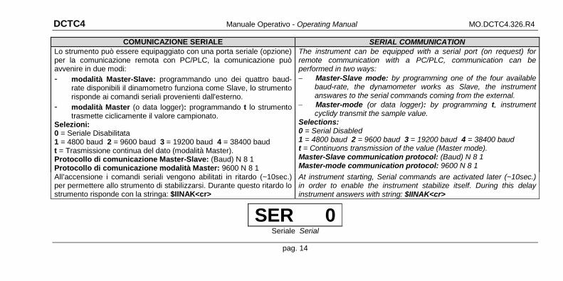
COMUNICAZIONE SERIALE SERIAL COMMUNICATION Lo strumento può essere equipaggiato con una porta seriale (opzione) per la comunicazione remota con PC/PLC, la comunicazione può avvenire in due modi: - modalità Master-Slave: programmando uno dei quattro baud-
rate disponibili il dinamometro funziona come Slave, lo strumento risponde ai comandi seriali provenienti dall'esterno.
- modalità Master (o data logger): programmando t lo strumento trasmette ciclicamente il valore campionato.
Selezioni: 0 = Seriale Disabilitata 1 = 4800 baud 2 = 9600 baud 3 = 19200 baud 4 = 38400 baud t = Trasmissione continua del dato (modalità Master). Protocollo di comunicazione Master-Slave: (Baud) N 8 1 Protocollo di comunicazione modalità Master: 9600 N 8 1
The instrument can be equipped with a serial port (on request) for remote communication with a PC/PLC, communication can be performed in two ways: − Master-Slave mode: by programming one of the four available
baud-rate, the dynamometer works as Slave, the instrument answares to the serial commands coming from the external.
− Master-mode (or data logger): by programming t, instrument cyclidy transmit the sample value.
Selections: 0 = Serial Disabled 1 = 4800 baud 2 = 9600 baud 3 = 19200 baud 4 = 38400 baud t = Continuons transmission of the value (Master mode). Master-Slave communication protocol: (Baud) N 8 1 Master-mode communication protocol: 9600 N 8 1
All’accensione i comandi seriali vengono abilitati in ritardo (~10sec.) per permettere allo strumento di stabilizzarsi. Durante questo ritardo lo strumento risponde con la stringa: $IINAK<cr>
At instrument starting, Serial commands are activated later (~10sec.) in order to enable the instrument stabilize itself. During this delay instrument answers with string: $IINAK<cr>
SER 0 Seriale Serial
pag. 14
DCTC4 Manuale Operativo - Operating Manual MO.DCTC4.326.R4
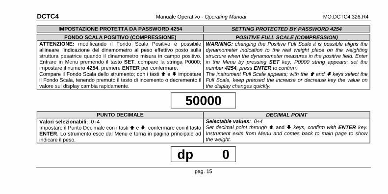
IMPOSTAZIONE PROTETTA DA PASSWORD 4254 SETTING PROTECTED BY PASSWORD 4254
FONDO SCALA POSITIVO (COMPRESSIONE) POSITIVE FULL SCALE (COMPRESSION) ATTENZIONE: modificando il Fondo Scala Positivo è possibile allineare l'indicazione del dinamometro al peso effettivo posto sulla struttura pesatrice quando il dinamometro misura in campo positivo. Entrare in Menu premendo il tasto SET, compare la stringa P0000; impostare il numero 4254, premere ENTER per confermare. Compare il Fondo Scala dello strumento; con i tasti e impostare il Fondo Scala, tenendo premuto il tasto di incemento o decremento il valore sul display cambia rapidamente.
WARNING: changing the Positive Full Scale it is possible aligns the dynamometer indication to the real weight place on the weighting structure when the dynamometer measures in the positive field. Enter in the Menu by pressing SET key, P0000 string appears; set the number 4254, press ENTER to confirm. The instrument Full Scale appears; with the and keys select the Full Scale, keep pressed the increase or decrease key the value on the display changes quickly.
50000
PUNTO DECIMALE DECIMAL POINT Valori selezionabili: 0÷4 Impostare il Punto Decimale con i tasti e , confermare con il tasto ENTER. Lo strumento esce dal Menu e torna in pagina principale ad indicare il peso.
Selectable values: 0÷4 Set decimal point through and keys, confirm with ENTER key. Instrument exits from Menu and comes back to main page to show the weight.
dp 0
pag. 15
DCTC4 Manuale Operativo - Operating Manual MO.DCTC4.326.R4
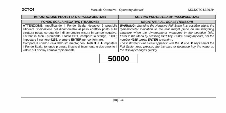
IMPOSTAZIONE PROTETTA DA PASSWORD 4255 SETTING PROTECTED BY PASSWORD 4255
FONDO SCALA NEGATIVO (TRAZIONE) NEGATIVE FULL SCALE (TENSION) ATTENZIONE: modificando il Fondo Scala Negativo è possibile allineare l'indicazione del dinamometro al peso effettivo posto sulla struttura pesatrice quando il dinamometro misura in campo negativo. Entrare in Menu premendo il tasto SET, compare la stringa P0000; impostare il numero 4255, premere ENTER per confermare. Compare il Fondo Scala dello strumento; con i tasti e impostare il Fondo Scala, tenendo premuto il tasto di incemento o decremento il valore sul display cambia rapidamente.
WARNING: changing the Negative Full Scale it is possible aligns the dynamometer indication to the real weight place on the weighting structure when the dynamometer measures in the negative field. Enter in the Menu by pressing SET key, P0000 string appears; set the number 4255, press ENTER to confirm. The instrument Full Scale appears; with the and keys select the Full Scale, keep pressed the increase or decrease key the value on the display changes quickly.
50000
pag. 16

DCTC4 Manuale Operativo - Operating Manual MO.DCTC4.326.R4
FUNZIONE DI ZERO ZERO FUNCTION La funzione ZERO serve per azzerare l’indicazione; il valore indicato prima dell’attivazione viene sottratto al valore campionato, il risultato (0) viene mostrato sul display. La funzione agisce su tutto il campo di misura (100%), lo stato viene memorizzato; all’accensione la funzione riprende lo stato precedente lo spegnimento. Per attivare la funzione, tenere premuto il tasto ZERO per circa 3sec.; per disattivare la funzione tenere premuto il tasto ZERO per circa 6sec.
ZERO function is used to zero instrument indication; value displayed by the instrument, before function activation, is deducted from sampled value, the result (0) is showed on the display. The function acts on the entire measurement range (100%). Function status is stored permanently; at instrument starting, function takes back the status stored before switching off. To connect the function keep pressed ZERO key for about 3sec.; to disconnect the function keep pressed ZERO key for about 6sec.
FUNZIONE DI PICCO PEAK FUNCTION La funzione PICCO rileva il valore minimo e massimo di una misura. Per attivare la funzione si deve premere il tasto PEAK, attivata la funzione il display lampeggia; la velocità di rilevamento è proporzionale al filtro utilizzato, per avere la massima velocità impostare il filtro 0 (10mS). Allo spegnimento del dinamometro la funzione viene disattivata.
PEAK function detects the minimum and maximum value of a measurement. To enable the function press PEAK key, when function is activated, the display lights; reading speed is proportional to the filter used, in order to work at max speed, set filter 0 (10mS). At dynamometer switching off, function is disconnected.
pag. 17
DCTC4 Manuale Operativo - Operating Manual MO.DCTC4.326.R4
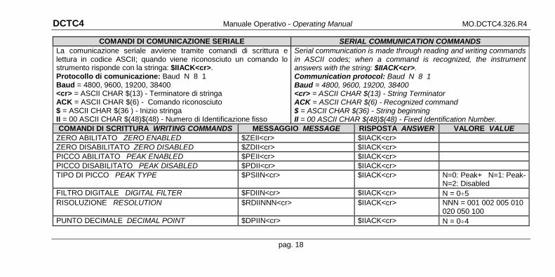
COMANDI DI COMUNICAZIONE SERIALE SERIAL COMMUNICATION COMMANDS La comunicazione seriale avviene tramite comandi di scrittura e lettura in codice ASCII; quando viene riconosciuto un comando lo strumento risponde con la stringa: $IIACK<cr>. Protocollo di comunicazione: Baud N 8 1 Baud = 4800, 9600, 19200, 38400 <cr> = ASCII CHAR $(13) - Terminatore di stringa ACK = ASCII CHAR $(6) - Comando riconosciuto $ = ASCII CHAR $(36 ) - Inizio stringa II = 00 ASCII CHAR $(48)$(48) - Numero di Identificazione fisso
Serial communication is made through reading and writing commands in ASCII codes; when a command is recognized, the instrument answers with the string: $IIACK<cr>. Communication protocol: Baud N 8 1 Baud = 4800, 9600, 19200, 38400 <cr> = ASCII CHAR $(13) - String Terminator ACK = ASCII CHAR $(6) - Recognized command $ = ASCII CHAR $(36) - String beginning II = 00 ASCII CHAR $(48)$(48) - Fixed Identification Number.
COMANDI DI SCRITTURA WRITING COMMANDS MESSAGGIO MESSAGE RISPOSTA ANSWER VALORE VALUE ZERO ABILITATO ZERO ENABLED $ZEII<cr> $IIACK<cr> ZERO DISABILITATO ZERO DISABLED $ZDII<cr> $IIACK<cr> PICCO ABILITATO PEAK ENABLED $PEII<cr> $IIACK<cr> PICCO DISABILITATO PEAK DISABLED $PDII<cr> $IIACK<cr> TIPO DI PICCO PEAK TYPE $PSIIN<cr> $IIACK<cr> N=0: Peak+ N=1: Peak-
N=2: Disabled FILTRO DIGITALE DIGITAL FILTER $FDIIN<cr> $IIACK<cr> N = 0÷5 RISOLUZIONE RESOLUTION $RDIINNN<cr> $IIACK<cr> NNN = 001 002 005 010
020 050 100 PUNTO DECIMALE DECIMAL POINT $DPIIN<cr> $IIACK<cr> N = 0÷4
pag. 18
DCTC4 Manuale Operativo - Operating Manual MO.DCTC4.326.R4
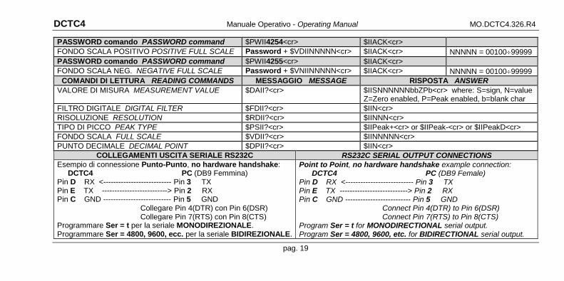
PASSWORD comando PASSWORD command $PWII4254<cr> $IIACK<cr> FONDO SCALA POSITIVO POSITIVE FULL SCALE Password + $VDIINNNNN<cr> $IIACK<cr> NNNNN = 00100÷99999 PASSWORD comando PASSWORD command $PWII4255<cr> $IIACK<cr> FONDO SCALA NEG. NEGATIVE FULL SCALE Password + $VNIINNNNN<cr> $IIACK<cr> NNNNN = 00100÷99999
COMANDI DI LETTURA READING COMMANDS MESSAGGIO MESSAGE RISPOSTA ANSWER VALORE DI MISURA MEASUREMENT VALUE $DAII?<cr> $IISNNNNNNbbZPb<cr> where: S=sign, N=value
Z=Zero enabled, P=Peak enabled, b=blank char FILTRO DIGITALE DIGITAL FILTER $FDII?<cr> $IIN<cr> RISOLUZIONE RESOLUTION $RDII?<cr> $IINNN<cr> TIPO DI PICCO PEAK TYPE $PSII?<cr> $IIPeak+<cr> or $IIPeak-<cr> or $IIPeakD<cr> FONDO SCALA FULL SCALE $VDII?<cr> $IINNNNN<cr> PUNTO DECIMALE DECIMAL POINT $DPII?<cr> $IIN<cr>
COLLEGAMENTI USCITA SERIALE RS232C RS232C SERIAL OUTPUT CONNECTIONS Esempio di connessione Punto-Punto, no hardware handshake: DCTC4 PC (DB9 Femmina) Pin D RX <--------------------------- Pin 3 TX Pin E TX --------------------------> Pin 2 RX Pin C GND --------------------------- Pin 5 GND
Collegare Pin 4(DTR) con Pin 6(DSR) Collegare Pin 7(RTS) con Pin 8(CTS)
Programmare Ser = t per la seriale MONODIREZIONALE. Programmare Ser = 4800, 9600, ecc. per la seriale BIDIREZIONALE.
Point to Point, no hardware handshake example connection: DCTC4 PC (DB9 Female) Pin D RX <--------------------------- Pin 3 TX Pin E TX ---------------------------> Pin 2 RX Pin C GND -------------------------- Pin 5 GND
Connect Pin 4(DTR) to Pin 6(DSR) Connect Pin 7(RTS) to Pin 8(CTS)
Program Ser = t for MONODIRECTIONAL serial output. Program Ser = 4800, 9600, etc. for BIDIRECTIONAL serial output.
pag. 19
DCTC4 Manuale Operativo - Operating Manual MO.DCTC4.326.R4
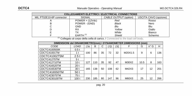
COLLEGAMENTI ELETTRICI / ELECTRICAL CONNECTIONS MIL PT02E10-6P connector SIGNAL CABLE OUTPUT (option) USCITA CAVO (opzione)
A B C D E F
POWER + (12Vdc) POWER - (GND) GND RX TX EARTH (1)
Red Black Blu Yellow White Shield
Rosso Nero Blu Giallo Bianco Schermo
(1) Collegato al corpo della cella di carico. / Connected to the load cell body.
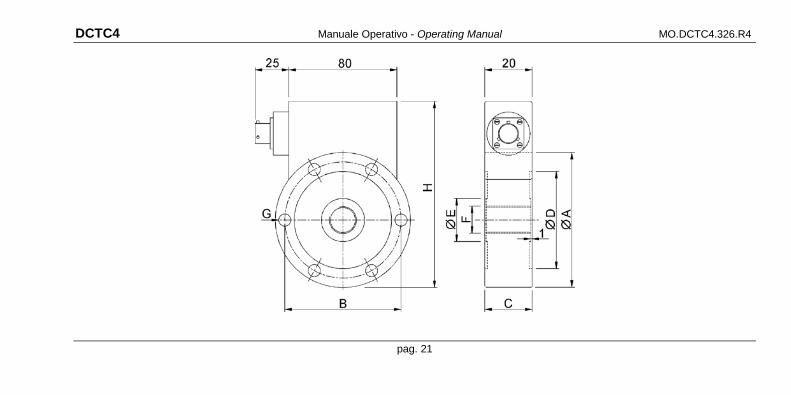
DIMENSIONI del DINAMOMETRO(mm) / DYNAMOMETER DIMENSIONS (mm) CODE LOAD ∅A B C ∅D ∅E F G n° G H
CDCTC4100500K 0.5 t CDCTC41001TM 1 t 100 86 35 72 32 M20X1.5 9 6 136 CDCTC41002T5M 2.5 t CDCTC41275TM 5 t
127
110
35
92
47
M30X2
10.5
8
163 CDCTC412710TM 10 t CDCTC416520TM 20 t CDCTC416530TM 30 t 165 138 50 108 62 M42X3 17 12 201 CDCTC416550TM 50 t CDCTC423075TM 75 t
230
185
80
147
96
M60X3
25
12
266 CDCTC4230100TM 100 t
pag. 20
DCTC4 Manuale Operativo - Operating Manual MO.DCTC4.326.R4
pag. 21
DCTC4 Manuale Operativo - Operating Manual MO.DCTC4.326.R4
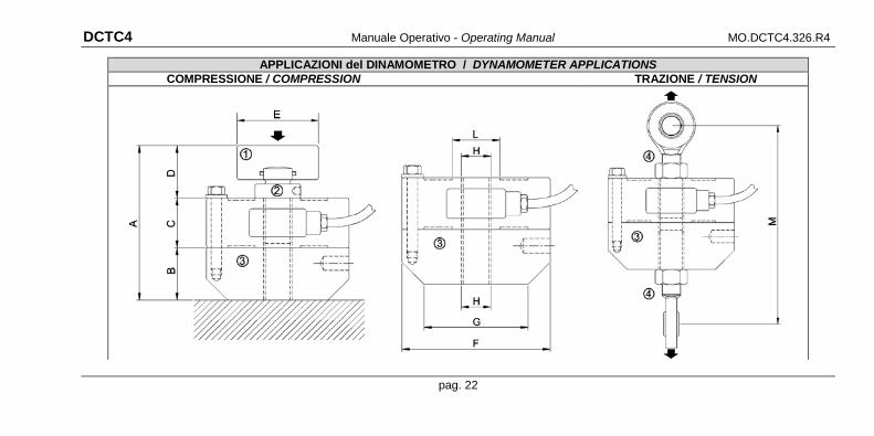
APPLICAZIONI del DINAMOMETRO / DYNAMOMETER APPLICATIONS COMPRESSIONE / COMPRESSION TRAZIONE / TENSION
pag. 22
DCTC4 Manuale Operativo - Operating Manual MO.DCTC4.326.R4
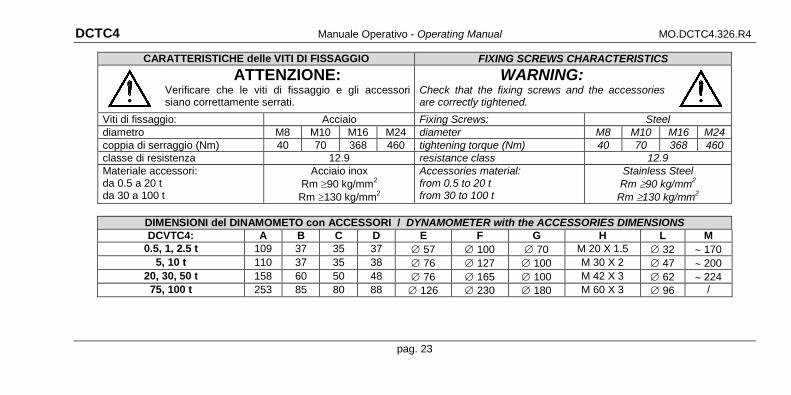
CARATTERISTICHE delle VITI DI FISSAGGIO FIXING SCREWS CHARACTERISTICS
ATTENZIONE: Verificare che le viti di fissaggio e gli accessori siano correttamente serrati.
WARNING: Check that the fixing screws and the accessories are correctly tightened.
Viti di fissaggio: Acciaio Fixing Screws: Steel diametro M8 M10 M16 M24 diameter M8 M10 M16 M24 coppia di serraggio (Nm) 40 70 368 460 tightening torque (Nm) 40 70 368 460 classe di resistenza 12.9 resistance class 12.9 Materiale accessori: da 0.5 a 20 t da 30 a 100 t
Acciaio inox Rm ≥90 kg/mm2 Rm ≥130 kg/mm2
Accessories material: from 0.5 to 20 t from 30 to 100 t
Stainless Steel Rm ≥90 kg/mm2
Rm ≥130 kg/mm2
DIMENSIONI del DINAMOMETO con ACCESSORI / DYNAMOMETER with the ACCESSORIES DIMENSIONS DCVTC4: A B C D E F G H L M
0.5, 1, 2.5 t 109 37 35 37 ∅ 57 ∅ 100 ∅ 70 M 20 X 1.5 ∅ 32 ∼ 170 5, 10 t 110 37 35 38 ∅ 76 ∅ 127 ∅ 100 M 30 X 2 ∅ 47 ∼ 200
20, 30, 50 t 158 60 50 48 ∅ 76 ∅ 165 ∅ 100 M 42 X 3 ∅ 62 ∼ 224 75, 100 t 253 85 80 88 ∅ 126 ∅ 230 ∅ 180 M 60 X 3 ∅ 96 /
pag. 23
DCTC4 Manuale Operativo - Operating Manual MO.DCTC4.326.R4
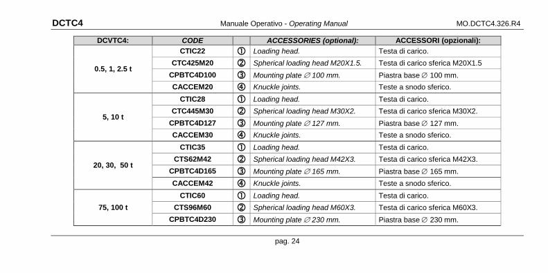
DCVTC4: CODE ACCESSORIES (optional): ACCESSORI (opzionali):
0.5, 1, 2.5 t
CTIC22 Loading head. Testa di carico. CTC425M20 Spherical loading head M20X1.5. Testa di carico sferica M20X1.5
CPBTC4D100 Mounting plate ∅ 100 mm. Piastra base ∅ 100 mm. CACCEM20 Knuckle joints. Teste a snodo sferico.
5, 10 t
CTIC28 Loading head. Testa di carico. CTC445M30 Spherical loading head M30X2. Testa di carico sferica M30X2.
CPBTC4D127 Mounting plate ∅ 127 mm. Piastra base ∅ 127 mm. CACCEM30 Knuckle joints. Teste a snodo sferico.
20, 30, 50 t
CTIC35 Loading head. Testa di carico. CTS62M42 Spherical loading head M42X3. Testa di carico sferica M42X3.
CPBTC4D165 Mounting plate ∅ 165 mm. Piastra base ∅ 165 mm. CACCEM42 Knuckle joints. Teste a snodo sferico.
75, 100 t CTIC60 Loading head. Testa di carico.
CTS96M60 Spherical loading head M60X3. Testa di carico sferica M60X3. CPBTC4D230 Mounting plate ∅ 230 mm. Piastra base ∅ 230 mm.
pag. 24
DCTC4 Manuale Operativo - Operating Manual MO.DCTC4.326.R4
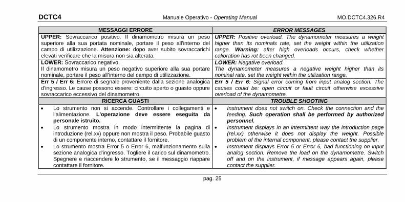
MESSAGGI ERRORE ERROR MESSAGES UPPER: Sovraccarico positivo. Il dinamometro misura un peso superiore alla sua portata nominale, portare il peso all’interno del campo di utilizzazione. Attenzione: dopo aver subito sovraccarichi elevati verificare che la misura non sia alterata.
UPPER: Positive overload. The dynamometer measures a weight higher than its nominals rate, set the weight within the utilization range. Warning: after high overloads occurs, check whether calibration has rot been changed.
LOWER: Sovraccarico negativo. Il dinamometro misura un peso negativo superiore alla sua portare nominale, portare il peso all’interno del campo di utilizzazione.
LOWER: Negative overload. The dynamometer measures a negative weight higher than its nominal rate, set the weight within the utilization range.
Err 5 / Err 6: Errore di segnale proveniente dalla sezione analogica d'ingresso. Le cause possono essere: circuito aperto o guasto oppure sovraccarico eccessivo del dinamometro.
Err 5 / Err 6: Signal error coming from input analog section. The causes could be: open circuit or fault circuit otherwise excessive overload of the dynamometre.
RICERCA GUASTI TROUBLE SHOOTING • Lo strumento non si accende. Controllare i collegamenti e
l'alimentazione. L'operazione deve essere eseguita da personale istruito.
• Lo strumento mostra in modo intermittente la pagina di introduzione (rel.xx) oppure non mostra il peso. Probabile guasto di un componente interno, contattare il fornitore.
• Lo strumento mostra Error 5 o Error 6, malfunzionamento sulla sezione analogica d'ingresso. Togliere il carico sul dinamometro. Spegnere e riaccendere lo strumento, se il messaggio riappare contattare il fornitore.
• Instrument does not switch on. Check the connection and the feeding. Such operation shall be performed by authorized personnel.
• Instrument displays in an intermittent way the introduction page (rel.xx) otherwise it does not display the weight. Possible problem of the internal component, please contact the supplier.
• Instrument displays Error 5 or Error 6, bad functioning on input analog section. Remove the load on the dynamometre. Switch off and on the instrument, if message appears again, please contact the supplier.
pag. 25