Cl 025 x g 050 - DAHANANdahanan.eu/cms/wp-content/uploads/V400CL.pdf · Cl 025 x g 050 + MTa10x150...
6
Integrated Hydraulic Cylinders, Heavy Duty Series EN Cilindri oleodinamici integrati, serie pesante IT 400 BAR V400CL Integrierter Hydraulikzylinder, Heavy Duty-Serie DE Vérins hydrauliques intégrés, serie lourde FR V400CL
Transcript of Cl 025 x g 050 - DAHANANdahanan.eu/cms/wp-content/uploads/V400CL.pdf · Cl 025 x g 050 + MTa10x150...

Integrated Hydraulic Cylinders,Heavy Duty Seriese
n
Cilindri oleodinamici integrati, serie pesanteit
400 bar
v4
00
Cl
Integrierter Hydraulikzylinder,Heavy Duty-Serie
de
vérins hydrauliques intégrés, serie lourdefr
v4
00
cl
l2 l3
v4
00
cl
v4
00
cl
Cl 025 x
ØX
016
025
032
040
050
063
080
100
Page Seite Page Pagina l4 l5 > l6
X
Y
g
l7
050
l4
Z
MTa10x150
l8
Cyl
ind
er M
od
el
Zylin
der
Mo
del
l
Mo
dèl
e d
u V
érin
Mo
del
lo c
ilind
ro
Bo
reB
ohr
ung
alé
sage
ale
sagg
io
Cla
mp
ing
Styl
e
Bef
esti
gung
s a
rt
Fixa
tio
n
Fiss
aggi
o
Ro
d e
nd S
tyle
Ko
lben
stan
gen
ausf
ühru
ng
extr
émit
é d
e la
tig
e
estr
emit
à st
elo
Stro
keH
ublä
nge
Co
urse
Co
rsa
Ro
d a
cces
sori
es
Zub
ehö
r K
olb
enst
ange
acc
esso
ires
de
la t
ige
acc
esso
ri s
telo
ØY
ØX
Z
+
OrDer CODeen
CODICe OrDIneITbeSTellCODeDe
CODe COMManDefr
Maximum Working Pressure
Maximale Druck
Pression maximale d’exercice
Pressione massima di esercizio
Maximum nominal Delivery (Pushing)
Nennwert Max. Durchflussmenge(beim ausfahren)
Débit nominal maximum (en poussée)
Portata massima nominale
ØX MPa - (bar) - PSI l/min
16 36(360) - 5220 1
25 36(360) - 5220 3
32 36(360) - 5220 5
40 36(360) - 5220 7
50 36(360) - 5220 12
63 36(360) - 5220 18
80 24(240) - 3480 30
100 24(240) - 3480 45
Max Mass applicable at Max Speed
Max. bewegbare Massebei max. geschwindigkeit.
Masse maximum applicableà la vitesse maxi
Massa max applicabilealla velocità max
Maximum Piston Speed
Maximale geschwindigkeit des Kolbens
Vitesse maximum du vérin
Velocità massima pistone
Maximum Working temperature
Max. Betriebstemperatur
température max. d’exercice
temperatura massima esercizio
ØX Kg m/s
16 2
25 4
0,1 160°C - +320°F
32 10
40 17
50 25
63 30
80 40
100 45
ØX = Bore Bohrung alésage alesaggio
TeCHnICal anD WOrKIng CHaraCTerISTICS CHarTen
Tabelle TeCHnISCHe MerKMale UnD fUnKTIOnDe
TableaU DeS CaraCTérISTIqUeS TeCHnIqUeS eT De fOnCTIOnneMenT fr
Tabella CaraTTerISTICHe TeCnICHe e DI fUnZIOnaMenTOIT
g
Female Metric thread
Metrisches innengewinde
taraudage métrique
Filetto femmina metrico
a
Male Metric thread
Metrisches aussengewinde
Filetage métrique
Filetto maschio metrico
i
Female UnF thread
UnF innengewinde
taraudage UnF-UneF
Filetto femmina UnF
H
UnF-UneF Male thread
UnF-UneF aussengewinde
Filetage male UnF-UneF
Filetto maschio UnF-UneF
#
none
Keiner
aucun
nessuno
Mta
Male thread
aussengewinde
Filetage
Filetto maschio
MFa
Floating Joint
Hammerkopf
tenon
testa a martello
DFa
Floating Joint with Female
Hammerkopf mitgegenstück
tenon male/femelle
testa a martello con femmina
l4 l5
v4
00
cl
v4
00
cl
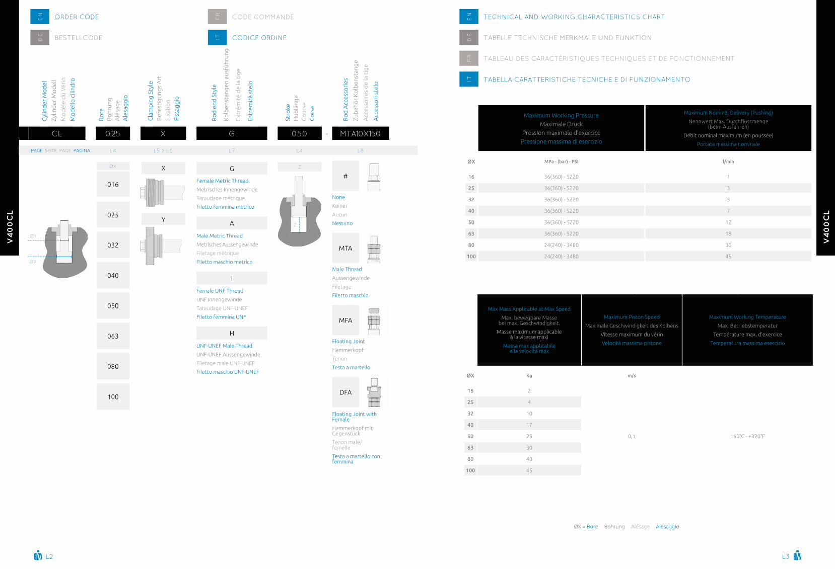
tableau des forces de poussée et de traction en dan (1 dan=1 kgf)
tabella forze in spinta e tiro in dan (1 dan = 1 kgf)
8 MPa80 bar
1160 PSI
14 MPa140 bar
2030 PSI
20 MPa200 bar
2900 PSI
25 MPa250 bar
3626 PSI
30 MPa300 bar
4350 PSI
ØX ØY th tr th tr th tr th tr th tr
016 10 161 98 281 171 402 245 502 306 603 367
025 18 393 189 687 331 981 473 1227 591 1472 709
032 22 643 339 1125 593 1608 848 2010 1060 2412 1272
040 22 1005 701 1758 1226 2512 1752 3140 2190 3768 2628
050 28 1570 1078 2748 1886 3925 2694 4906 3368 5888 4041
063 28 2493 2000 4362 3500 6231 5000 7789 6251 9347 7501
080 36 4019 3205 7034 5609 10048 8013 12560 10017 - -
100 45 6280 5008 10990 8765 15700 12521 19625 15651 - -
bOre SIZe anD STrOKeen aléSageS eT COUrSeSfr
aleSaggIO e COrSaITKOlbenDUrCHMeSSer UnD HUblÄngeDe
thrust Druck Poussée Spinta traction Zug traction trazioneth tr
ZØX
Cl 025 x g 050 MTa10x150+
ØX Bore Bohrung alésage alesaggio ØY Rod Kolbenstange tige Stelo Stroke Hub Course CorsaZ
StanDaRD StROKeS StanDaRD HUBLÄngen COURSeS StanDaRD CORSe StanDaRD
SPeCiaL StROKeS SOnDeRHUBLÄngen COURSeS SPeCiaLeS CORSe SPeCiaLi
NOTES: The table above shows the maximum strokes for each version. The effective cylinder stroke will be the one determined by the customer, depending on the housing manufactured inside the mold. The effective stroke can actually be shorter than the maximum (but never less than quote “Q” at pages L5 and L6). In these cases the rodprojection – quote “WH” at page L7 – will be increased by the difference between the standard stroke chosen, as per here above, and the effective stroke manufactured.
AchTuNg: Die oben angegebenen Werte beziehen sich auf die maximal möglichen Hublängen je ausführung. Die tatsächliche Hublänge kann individuell über die tiefe des Kolbensitzes im Werkstuck bestimmt werden und daher auch kleiner als die maximal mogliche Lange sein (jedoch nie kleiner als Maß “Q” auf Seite L5 und L6).In diesem Fall verlangert sich der Überstand der Kolbenstange – siehe Maß “WH” auf Seite L7 – gegenuber des gewahlten Standardhubs – siehe obige Tabelle – und der tatsächlichen Hublänge.
NOTE: Le tableau indique les courses maximum pour chaque version. En definitive la course effective du verin sera celle determinee par le client en fonction de l’usinage du logement realise dans le moule. Cette derniere peut etre plus courte que la course maximum (mais jamais inferieure a la cote “Q” indiquees aux pages L5 et L6). Dans ce cas, la cote de depassement – “WH” page L7 – augmentera de la difference entre la course standard choisie, note sur le tableau ci-dessus, et la course effectivement realisee.
NOTE: Le corse sopra indicate sono quelle massime realizzabili nella relativa versione. In definitiva la corsa effettiva del cilindro sara quella determinata dal cliente in base alla lavorazione della camera del cilindro eseguita sullo stampo. Questa infatti potra anche essere inferiore alla corsa massima (ma mai inferiore alla quota “Q” di pag. L5 e L6).In questi casi la quota di sporgenza dello stelo – “WH” di pag. L7 – aumentera in misura pari alla differenza fra la corsa standard scelta, come in tabella sopra, e quellaeffettivamente eseguita.
table for push and pull forces in dan (1 dan = 1 kgf)
tabelle druck- und zugkraft in dan (1 dan=1 kgf)
Standard strokes table in mm Standard hublängen tabelle in mm tableau des course standards en mm tabella corse standard in mm
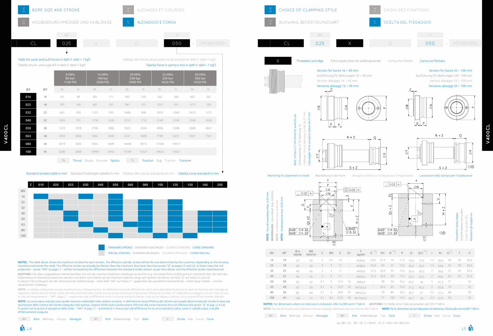
CHOICe Of ClaMpIng STyleen
aUSWaHl befeSTIgUngSarTDe
CHOIx DeS fIxaTIOnSfr
SCelTa Del fISSaggIOIT
ZØX
Cl 025 x g 050 MTa10x150+
NOTES: For dimensions where no tolerance is indicated, refer to Din norm 7168-m. AchTuNg: Für Maße ohne tolleranzangaben gilt Din 7168-m.
NOTE: Pour les dimensions où la tolerance n’est pas indiquée, addressez-vous aux normes Din 7168-m. NOTE: Per le dimensioni senza indicazione di tolleranza, riferirsi alla norma Din 7168-m.
ØX Bore Bohrung alésage alesaggio ØY Rod Kolbenstange tige Stelo Stroke Hub Course CorsaZ
eg. ØX = 25 , ØY = 18, Z = 50mm : R + Z = 34,6 + 50 = 84,6 mm
x threaded cartridge Führungsbuchse mit außengewinde Cartouche filetee Cartuccia filettata
ØX ØYØ A
h8/h8ØB
h9/h10c ØD E E1
F 6g/6h
g M+ N P Q Q1+ r R+ S+ T V
16 10 24 30 3 2,5 10 - M30x2 24,5 41,5 16 11,5 19,4 19,5 1,5 30,6 50 30 26,5
25 18 34 38 3 4 11 - M38x2 26,5 44 25 12,5 20,4 20,5 1,5 34,6 55 38 28,5
32 22 40 45 3 4 11 - M45x2 27,5 45,5 32 13,5 20,4 20,5 2 36,6 57 45 29,5
40 22 40 45 3 4 11 - M45x2 31,5 50,5 40 17,5 22,4 22,5 2 40,6 63 45 31,5
50 28 50 42 3,1 5 12,9 16 M60x2 - 58 50 16,2 29,7 46 2 41,3 71 - 32
63 28 63 50 3,1 6 14,9 18 M75x2,5 - 59,5 63 14,2 31,2 45,5 2 42,8 74 - 32
80 36 80 60 3,1 6 20,9 24 M95x2,5 - 70 80 16,2 34,7 51 2,5 51,3 86 - 39
100 45 100 72 3,1 8,5 22,9 26 M115x2,5 - 77 100 19,2 36,7 56 2,5 57,3 94 - 45
+ 0,050
+ 0,020
+ 0,050
+ 0,150
Version for bores 16 ÷ 40 mm
ausführung für Bohrungen 16 ÷ 40 mm
Version alésages 16 ÷ 40 mm
Versione alesaggi 16 ÷ 40 mm
Bo
re 1
6 ha
s a
27 m
m d
rive
fo
r w
renc
h us
e
Schl
üsse
lwei
te 2
7 fü
r B
ohr
ung
16
L’al
ésag
e 16
a u
n p
lan
po
ur la
cle
f d
e 27
mm
L’al
esag
gio
16
ha u
n p
iano
chi
ave
da
27 m
m
Version for bores 50 ÷ 100 mm
ausführung für Bohrungen 50÷ 100 mm
Version alésages 50 ÷ 100 mm
Versione alesaggi 50 ÷ 100 mm
Machining for placement on mold Bearbeitung in der Form Usinage à réaliser sur le moule pour l’implantation Lavorazioni nello stampo per l’installazione
NO
TE :
Out
-of-
roun
dne
ss M
ax. 0
,03
mm
BEM
ERK
uN
g :
Unr
und
heit
max
. 0,0
3mm
NO
TE :
Ova
lisat
ion
max
. 0,0
3 m
m
NO
TA :
Ova
lizza
zio
ne m
ax. 0
,03
mm
Smo
oth
en s
harp
ed
ges
Scha
rfe
Kan
ten
verr
und
en
Cas
ser
les
angl
es v
ifs
Ro
mp
ere
gli s
pig
oli
vivi
Z 010 020 025 030 040 050 060 080 100 120 150 160 200
ØX
16
25
32
40
50
63
80
100

l6 l7
v4
00
cl
v4
00
cl
CHOICe Of ClaMpIng STyleen
aUSWaHl befeSTIgUngSarTDe
CHOIx DeS fIxaTIOnSfr
SCelTa Del fISSaggIOIT
ZØX
Cl 025 y g 050 MTa10x150+
NOTES: For dimensions where no tolerance is indicated, refer to Din norm 7168-m.
AchTuNg: Für Maße ohne tolleranzangaben gilt Din 7168-m.
NOTE: Pour les dimensions où la tolerance n’est pas indiquée, addressez-vous aux normes Din 7168-m.
NOTE: Per le dimensioni senza indicazione di tolleranza, riferirsi alla norma Din 7168-m.
ØX Bore Bohrung alésage alesaggio ØY Rod Kolbenstange tige Stelo Stroke Hub Course CorsaZ
eg. ØX = 25 , ØY = 18, Z = 50mm : R + Z = 34,6 + 50 = 84,6 mm
y Flanged cartridge Fuhrungsbuchse zum flanschen Cartouche flasquee Cartuccia flangiata
NOTE : Out-of-roundness Max. 0,03 mm
BEMERKuNg : Unrundheit max. 0,03mm
NOTE : Ovalisation max. 0,03 mm
NOTA : Ovalizzazione max. 0,03 mm
Smoothen sharp edges
Scharfe Kanten verrunden
Casser les angles vifs
Rompere gli spigoli vivi
Machining for placement on mold
Bearbeitung in der Form
Usinage à réaliser sur le moule pour l’implantation
Lavorazioni nello stampo per l’installazione
ØX ØYØ A
h8/h8ØB1 c1 ØD ØD1 g I L M+ M1 ØN O P Q Q1+ r R+ S+ u V Y1
16 10 24 46 13 2,5 44 24,5 28 16,5 41,5 28,6 16 9 11,5 19,4 19,5 1,5 30,6 50 5,5 26,5 5,5
25 18 34 56 14 4 54 26,5 38 21,5 44 37,2 25 9 12,5 20,4 20,5 1,5 34,6 55 5,5 28,5 5,5
32 22 40 66 14 4 64 27,5 44 25,5 45,5 44,2 32 10,5 13,5 20,4 20,5 2 36,6 57 6,5 29,5 6,5
40 22 40 66 14 4 64 31,5 44 25,5 50,5 44,2 40 10,5 17,5 22,4 22,5 2 40,6 63 6,5 31,5 6,5
50 28 50 84 16 5 82 32,2 54 32 58 55,4 50 13,5 16,2 29,7 29,8 2 41,3 71 8,5 32 8,5
63 28 63 98 18 6 96 32,2 67 39 59,5 67,5 63 13,5 14,2 31,2 31,3 2 42,8 74 8,5 32 8,5
80 36 80 122 24 6 120 40,2 84 49 70 84,9 80 16,5 16,2 34,7 34,8 2,5 51,3 86 10,5 39 10,5
100 45 100 148 26 8,5 146 45,2 104 61 77 105,7 100 18,5 19,2 36,7 36,8 2,5 57,3 94 12,5 45 12,5
+ 0,050
+ 0,020
+ 0,050
+ 0,050
+ 0,150
ZØX
Cl 025 x g 050 MTa10x150+
CHOICe Of rOD enD STyleen
aUSWaHl KOlbenSTangenenDeDe
CHOIx De l’exTréMITé De la TIgefr
SCelTa Dell’ eSTreMITà DellO STelOIT
Description of rod end style
Beschreibung des kolbenstangenendes
Description du type d’extrémité de la tige
Descrizione tipo di estremità
NOTES: For dimensions where no tolerance is indicated, refer to Din norm 7168-m.
AchTuNg: Für Maße ohne tolleranzangaben gilt Din 7168-m.
NOTE: Pour les dimensions où la tolerance n’est pas indiquée, addressez-vous aux normes Din 7168-m.
NOTE: Per le dimensioni senza indicazione di tolleranza, riferirsi alla norma Din 7168-m.
ØX ØYc
D E FK
ØM P Wh+F WhMETRIc uNF-uNEF METRIc uNF-uNEF
16 10 M6×1 1/4-28 12 4 12 M8×1 5/16-24 9,5 8 21 6
25 18 M10×1,5 3/8-24 20 5 20 M14×1,5 9/16-18 17 15 31 8
32 22 M12×1,75 1/2-20 20 6 25 M16×1,5 5/8-18 21 18 37 9
40 22 M14×2 9/16-18 20 6 25 M16×1,5 5/8-18 21 18 37 9
50 28 M20×2,5 3/4-16 30 6 30 M20×1,5 3/4-16 27 24 42 9
63 28 M20×2,5 3/4-16 30 7 30 M20×1,5 3/4-16 28 24 43,5 10,5
80 36 M27×3 1/12 40 8 40 M27×2 1-12 35 32 54 11
100 45 M33×3,5 1-1/4-12 50 9 50 M33×2 1-1/4-12 44 40 65 12
ØX Bore Bohrung alésage alesaggio ØY Rod Kolbenstange tige Stelo Stroke Hub Course CorsaZ
g
Female Metric thread – StandardMetrisches innengewinde – Standardtaraudage métrique – StandardFiletto femmina metrico – Standard
a
Male Metric threadMetrisches aussengewindeFiletage métriqueFiletto maschio metrico
I
UnF-UneF Female thread (U.S.a. Standard)UnF-UneF innengewinde (U.S.a. Standard)taraudage UnF-UneF (Standard U.S.a.)Filetto femmina UnF-UneF (Standard U.S.a.)
H
UnF-UneF Male thread (U.S.a. Standard)UnF-UneF aussengewinde (U.S.a. Standard)Filetage Male UnF-UneF (Standard U.S.a.)Filetto maschio UnF-UneF (Standard U.S.a.)
l8 l9
v4
00
cl
v4
00
cl
ZØX
Cl 025 y g 050 MTa10x150+
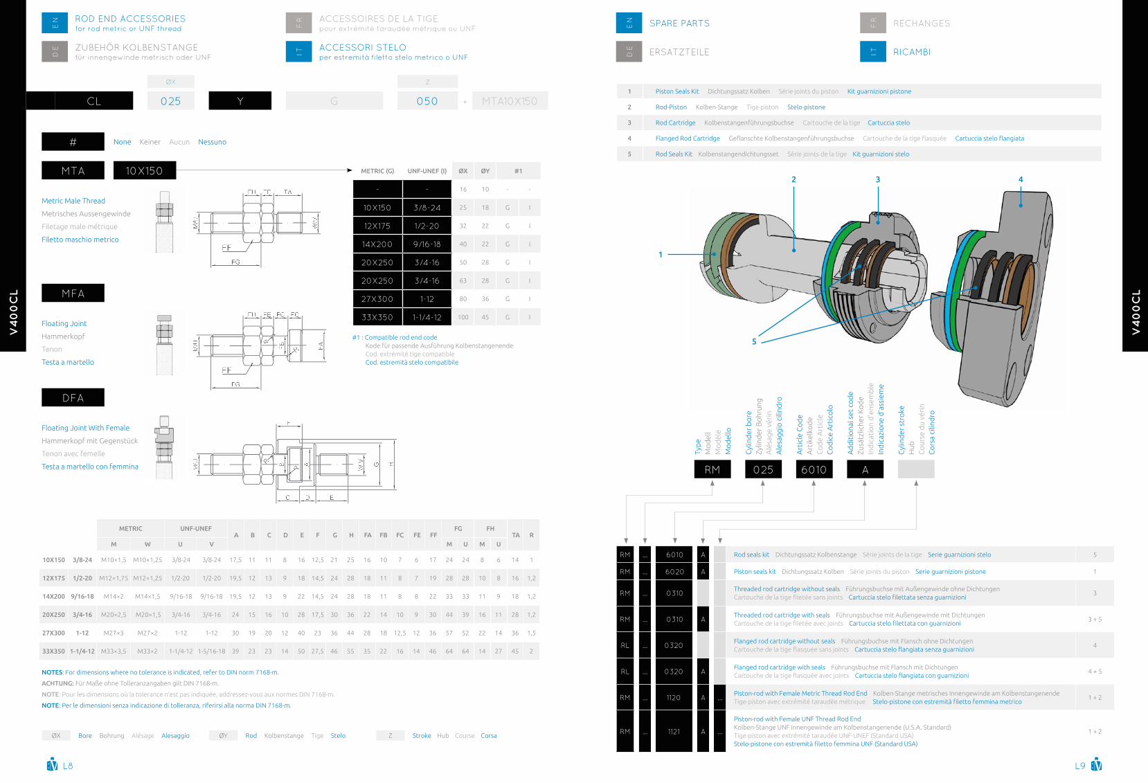
rOD enD aCCeSSOrIeSfor rod metric or Unf threade
naCCeSSOrI STelOper estremità filetto stelo metrico o UnfIT
ZUbeHÖr KOlbenSTangefür innengewinde metrisch oder UnfD
e
aCCeSSOIreS De la TIgepour extrémité taraudée métrique ou Unff
r
MTa
Metric Male thread
Metrisches aussengewinde
Filetage male métrique
Filetto maschio metrico
Mfa
Floating Joint
Hammerkopf
tenon
testa a martello
Dfa
Floating Joint With Female
Hammerkopf mit gegenstück
tenon avec femelle
testa a martello con femmina
10x150
#1 : Compatible rod end codeKode für passende ausführung KolbenstangenendeCod. extrémité tige compatibleCod. estremità stelo compatibile
METRIc (g) uNF-uNEF (I) ØX ØY #1
- - 16 10 - -
10x150 3/8-24 25 18 g i
12x175 1/2-20 32 22 g i
14x200 9/16-18 40 22 g i
20x250 3/4-16 50 28 g i
20x250 3/4-16 63 28 g i
27x300 1-12 80 36 g i
33x350 1-1/4-12 100 45 g i
NOTES: For dimensions where no tolerance is indicated, refer to Din norm 7168-m.
AchTuNg: Für Maße ohne tolleranzangaben gilt Din 7168-m.
NOTE: Pour les dimensions où la tolerance n’est pas indiquée, addressez-vous aux normes Din 7168-m.
NOTE: Per le dimensioni senza indicazione di tolleranza, riferirsi alla norma Din 7168-m.
ØX Bore Bohrung alésage alesaggio ØY Rod Kolbenstange tige Stelo Stroke Hub Course CorsaZ
METRIc uNF-uNEF A B c D E F g h FA FB Fc FE FF
Fg Fh TA R
M W u V M u M u
10X150 3/8-24 M10×1,5 M10×1,25 3/8-24 3/8-24 17,5 11 11 8 16 12,5 21 25 16 10 7 6 17 24 24 8 6 14 1
12X175 1/2-20 M12×1,75 M12×1,25 1/2-20 1/2-20 19,5 12 13 9 18 14,5 24 28 18 11 8 7 19 28 28 10 8 16 1,2
14X200 9/16-18 M14×2 M14×1,5 9/16-18 9/16-18 19,5 12 13 9 22 14,5 24 28 18 11 8 8 22 33 33 11 9 18 1,2
20X250 3/4-16 M20×2,5 M20×1,5 3/4-16 3/4-16 24 15 16 10 28 17,5 30 36 22 14 10 9 30 44 39 16 11 28 1,2
27X300 1-12 M27×3 M27×2 1-12 1-12 30 19 20 12 40 23 36 44 28 18 12,5 12 36 57 52 22 14 36 1,5
33X350 1-1/4-12 M33×3,5 M33×2 1-1/4-12 1-5/16-18 39 23 23 14 50 27,5 46 55 35 22 16 14 46 64 64 14 27 45 2
Spare parTSen
rICaMbIITerSaTZTeIleDe
reCHangeSfr
rM ... 6010 a Rod seals kit Dichtungssatz Kolbenstange Série joints de la tige Serie guarnizioni stelo 5
rM ... 6020 a Piston seals kit Dichtungssatz Kolben Série joints du piston Serie guarnizioni pistone 1
rM ... 0310 threaded rod cartridge without seals Führungsbuchse mit außengewinde ohne DichtungenCartouche de la tige filetee sans joints Cartuccia stelo filettata senza guarnizioni
3
rM ... 0310 a threaded rod cartridge with seals Führungsbuchse mit außengewinde mit DichtungenCartouche de la tige filetee avec joints Cartuccia stelo filettata con guarnizioni
3 + 5
rl ... 0320 Flanged rod cartridge without seals Führungsbuchse mit Flansch ohne DichtungenCartouche de la tige flasquee sans joints Cartuccia stelo flangiata senza guarnizioni
4
rl ... 0320 a Flanged rod cartridge with seals Führungsbuchse mit Flansch mit DichtungenCartouche de la tige flasquee avec joints Cartuccia stelo flangiata con guarnizioni
4 + 5
rM ... 1120 a ... Piston-rod with Female Metric thread Rod end Kolben-Stange metrisches innengewinde am Kolbenstangenendetige-piston avec extrémité taraudée métrique Stelo-pistone con estremita filetto femmina metrico
1 + 2
rM ... 1121 a ...
Piston-rod with Female UnF thread Rod endKolben-Stange UnF innengewinde am Kolbenstangenende (U.S.a. Standard)tige-piston avec extrémité taraudée UnF-UneF (Standard USa)Stelo-pistone con estremita filetto femmina UNF (Standard USA)
1 + 2
rM
typ
eM
od
ell
Mo
dèl
eM
od
ello
025
Cyl
ind
er b
ore
Zylin
der
Bo
hrun
ga
lésa
ge v
érin
ale
sagg
io c
ilind
ro
6010
art
icle
Co
de
art
ikel
kod
eC
od
e a
rtic
leC
od
ice
art
ico
lo
a
ad
dit
iona
l set
co
de
Zusä
tzlic
her
Ko
de
ind
icat
ion
d’e
nsem
ble
ind
icaz
ione
d’a
ssie
me
Cyl
ind
er s
tro
keH
ubC
our
se d
u vé
rin
Co
rsa
cilin
dro
1 Piston Seals Kit Dichtungssatz Kolben Série joints du piston Kit guarnizioni pistone
2 Rod-Piston Kolben-Stange tige-piston Stelo-pistone
3 Rod Cartridge Kolbenstangenführungsbuchse Cartouche de la tige Cartuccia stelo
4 Flanged Rod Cartridge Geflanschte Kolbenstangenfuhrungsbuchse Cartouche de la tige flasquee Cartuccia stelo flangiata
5 Rod Seals Kit Kolbenstangendichtungsset Série joints de la tige Kit guarnizioni stelo
1
2 3 4
5
# none Keiner aucun nessuno

l10
v4
00
cl