CILINDRI MOLLA AD AZOTO SERIE NITROGEN GAS … · lo stelo e la ghiera, sono costruiti in acciaio...
23
CILINDRI MOLLA AD AZOTO SERIE NITROGEN GAS SPRINGS SERIES
Transcript of CILINDRI MOLLA AD AZOTO SERIE NITROGEN GAS … · lo stelo e la ghiera, sono costruiti in acciaio...
CILINDRI MOLLA AD AZOTO SERIENITROGEN GAS SPRINGS SERIES
2
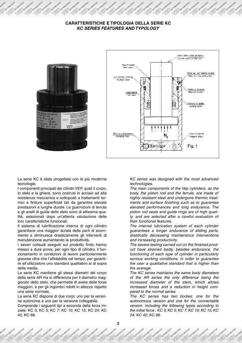
La serie KC è stata progettata con le più modernetecnologie.I componenti principali dei cilindri VEP, quali il corpo,lo stelo e la ghiera, sono costruiti in acciaio ad altaresistenza meccanica e sottoposti a trattamenti ter-mici e finiture superficiali tali da garantire elevateprestazioni e lunghe durate. Le guarnizioni di tenutae gli anelli di guida dello stelo sono di altissima qua-lità, selezionati dopo un’attenta valutazione delleloro caratteristiche funzionali.Il sistema di lubrificazione interna di ogni cilindrogarantisce una maggior durata delle parti di scorri-mento e diminuisce drasticamente gli interventi dimanutenzione aumentando la produttività.I severi collaudi eseguiti sul prodotto finito hannomesso a dura prova, per ogni tipo di cilindro, il fun-zionamento in condizioni di lavoro particolarmentegravose oltre che l’affidabilità nel tempo, per garanti-re all’utilizzatore uno standard qualitativo al di sopradella media.La serie KC mantiene gli stessi diametri del corpodella serie AR ma si differenzia per il diametro mag-giorato dello stelo, che permette di avere delle forzemaggiori, e per gli ingombri ridotti in altezza rispettouna serie normale.La serie KC dispone di due corpi: uno per la versio-ne autonoma e uno per la versione collegabile.Comprende i seguenti tipi a seconda della forza ini-ziale: KC 3; KC 5; KC 7; KC 10; KC 15; KC 24; KC42; KC 66.
KC series was designed with the most advancedtechnologies.The main components of the Vep cylinders, as thebody, the piston rod and the ferrule, are made ofhighly resistant steel and undergone thermic treat-ments and surface finishing such as to guaranteeelevated performances and long endurance. Thepiston rod seals and guide rings are of high quali-ty, and are selected after a careful evaluation oftheir functional features.The internal lubrication system of each cylinderguarantees a longer endurance of sliding parts,drastically decreasing maintenance interventionsand increasing productivity.The severe testing carried out on the finished prod-uct have strained badly, besides endurance, thefunctioning of each type of cylinder in particularlyserious working conditions, in order to guaranteethe user a qualitative standard that is higher thanthe average.The KC series maintains the same body diametersof the AR series the only difference being theincreased diameter of the stem, which allowsincreased forces and a reduction in height com-pared to the normal series.The KC series has two bodies: one for theautonomous version and one for the connectableversion. Including the following types according tothe initial force : KC 3; KC 5; KC 7; KC 10; KC 15; KC24; KC 42; KC 66.
CARATTERISTICHE E TIPOLOGIA DELLA SERIE KCKC SERIES FEATURES AND TYPOLOGY
SCELTA DEL TIPO DI CILINDROSELECTION OF CYLINDER TYPE
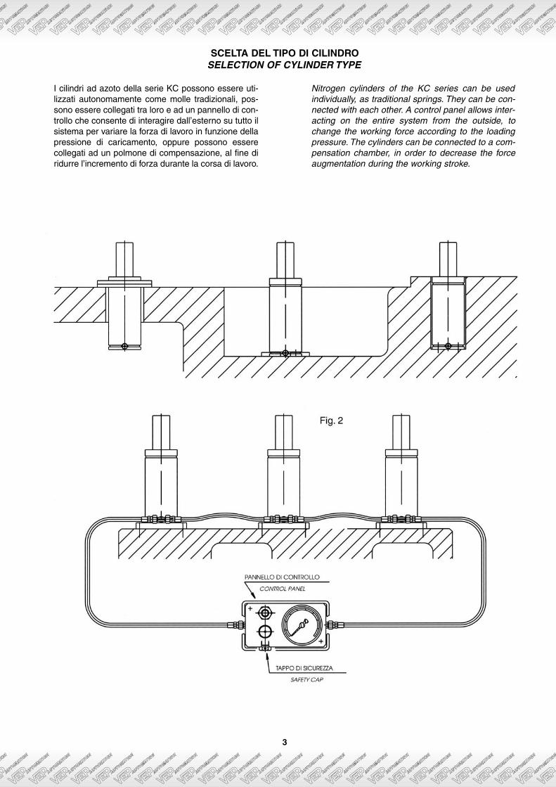
I cilindri ad azoto della serie KC possono essere uti-lizzati autonomamente come molle tradizionali, pos-sono essere collegati tra loro e ad un pannello di con-trollo che consente di interagire dall’esterno su tutto ilsistema per variare la forza di lavoro in funzione dellapressione di caricamento, oppure possono esserecollegati ad un polmone di compensazione, al fine diridurre l’incremento di forza durante la corsa di lavoro.
Nitrogen cylinders of the KC series can be usedindividually, as traditional springs. They can be con-nected with each other. A control panel allows inter-acting on the entire system from the outside, tochange the working force according to the loadingpressure. The cylinders can be connected to a com-pensation chamber, in order to decrease the forceaugmentation during the working stroke.
3
4
L’azoto, che è un gas inerte, viene introdotto nelcilindro fino al raggiungimento di una pressionemassima di 15 MPa. In condizioni di riposo la pres-sione del gas agisce sulla sezione dello stelo-pisto-ne (fig. 1), spingendo verso l’esterno con una frozarisultante pari alla forza iniziale del cilindro (la forzain KN è data dal prodotto della pressione in MPa perla sezione dello stelo in cm2).Durante il ciclo di funzionamento lo stelo rientra nelcorpo, comprime e diminuisce il volume del gas con-tenuto all’interno della camera e provoca l’incremen-to della forza.Il cilindro ad azoto ha un comportamento analogo aquello di una molla meccanica tradizionale, ma alcontrario di questa non necessita di alcun pre-carico.I cilindri della serie KC possono lavorare in qualsia-si posizione senza essere lubrificati. Essendo erme-ticamente chiusi conservano all’interno durante illoro lavoro l’apposito lubrificante introdotto almomento del montaggio, la particolarità delle guidedi scorrimento e le caratteristiche delle guarnizioniimpiegate concorrono efficacemente a garantireun’elevata affidabilità.Dopo un periodo di inattività dell’impianto è opportu-no far compiere ai cilindri-molla un lavoro preventivodi alcune decine di cicli completi al fine di ottimizza-re la tenuta delle guarnizioni.È preferibile evitare surriscaldamenti che inevitabil-mente provocherebbero aumenti di pressione all’in-terno dei cilindri; si consiglia di non superare i 12mt/minuto primo come velocità lineare dello stelo-pistone, valore che corrisponde a circa 1/5 di quelloammesso per le guarnizioni utilizzate.Il calcolo della cadenza di lavoro può essere effet-tuato nel modo seguente: tenendo conto che in unciclo lo stelo-pistone di una molla a gas esegue duecorse, una di andata ed una di ritorno, il numero deicicli per ogni minuto è dato dalla formula:
dove W è la velocità dello stelo-pistone (mm/minutoprimo) e S è la corsa (mm).
ESEMPIO: Se un cilindro esegue una corsa pari amm 150 alla velocità lineare di 8000 mm/minutoprimo, si avrà:
La pressione massima di caricamento dei cilindri adazoto deve essere di 15 MPa; con questo valore lapressione finale raggiunta in compressione è di 25MPa.Sui cilindri della serie KC non viene montato il tappodi sicurezza, poiché la realizzazione particolarmen-te robusta del prodotto è sufficiente a garantire unampio margine di affidabilità e di sicurezza.Nella versione collegata a sistema il tappo di sicu-rezza è a bordo del pannello di controllo.
FUNZIONAMENTO E CONDIZIONI DI LAVOROOPERATION AND WORKING CONDITIONS
n = W
C x 2
n = 8000
150 x 2 = 27 cicli al minuto primo
Nitrogen, an inert gas, is introduced inside untilthe maximum pressure of 15 MPa is reached. Inresting conditions the gas pressure acts on thepiston rod section (fig. 1), and pushes it outwardswith a resultant force equal to the cylinder start-ing force (the force measured in KN is obtainedfrom the product of the MPa pressure by the sec-tion of the piston rod in cm2).During the operating cycle the piston rod revers-es inside the tube, compressing and decreasingthe volume of the gas contained inside the cham-ber and provoking the force increase.The nitrogen cylinder has a behaviour similar tothat of a traditional mechanical spring, but con-trary to this one it doesn’t need any precharge.The KC series cylinders can work in any positionwithout being lubricated. Being hermeticallysealed while working they maintain inside thespecial lubricant introduced during assembling.The particularity of the sliding guides and thecharacteristics of the seals used effectively guar-antee an elevated reliability.After a period of inactivity of the system it isadvisable to preventively carry out about tencomplete working cycles of the spring-cylinderswith the purpose of optimizing the sealing.It is better to avoid overheating, as it inevitablywould provoke a rise in pressure inside the cylin-der; we advise not to pass the 12 mt/minute oflinear speed of the piston rod. The value corre-sponds to about 1/5 of the one admitted for theseals used.The calculation of the working rate can be doneas follows: considering that in one single cyclethe piston rod of the gas spring performs twostrokes, going and return, the number of cyclesper minute is given by the formula:
where W is the piston rod speed (mm/minute)and S is the stroke (mm)
EXAMPLE: If a cylinder performs a stroke equalto 150 mm at a linear speed of 8000 mm/minute,we will have:
The nitrogen cylinder maximum filling pressuremust be of 15 MPa; with this value the final pres-sure reached in compression is of 25 MPa.The safety cap is not assembled on the KCseries, since the particularly strong structure ofthe product is enough to guarantee a wide mar-gin of reliability and safety.In the system connected version the safety plugis assembled on the control panel.
n = W
C x 2
n = 8000
150 x 2 = 27 cycles on the first minute
Durata dei cilindri ad azotoInstallati correttamente ed in normali condizioni d’usoi cilindri ad azoto sono garantiti per uno sviluppo mini-mo di corsa complessivo pari a 75.000 metri lineari.Tale misura è data dalla somma delle corse di avan-zamento e di ritorno dello stelo-pistone.In condizioni di lavoro particolarmente critiche o percause esterne determinanti un malfunzionamento delprodotto può essere necessario un intervento manu-tentivo per la sostituzione delle guarnizioni di tenuta odelle parti danneggiate.L’utilizzatore può eseguire la manutenzione con gliattrezzi e le procedure indicati su questo catalogo.Naturalmente Vep Automation è disponibile a soddi-sfare le esigenze o le necessità dei clienti.
Temperatura d’esercizioLa temperatura massima d’esercizio consentita è di70°C. Temperature superiori possono danneggiare lecaratteristiche dei componenti di tenuta.La variazione della temperatura all’interno dei cilindriad azoto determina la variazione della pressione dicaricamento: l’aumento della temperatura di 1°C cor-risponde all’incremento della pressione dell’azoto,misurata in MPa, per un valore pari a 0,0367.
AvvertenzeAffinché i cilindri ad azoto possano svolgere il loro ser-vizio a lungo e nel migliore dei modi è opportuno chel’utilizzatore osservi nell’uso le seguenti precauzioni:• Evitare interventi o danneggiamenti su corpi e steli.• Non asportare prima dell’uso la rete di protezione
degli steli, urti accidentali possono scalfire o dan-neggiare la superficie.
• I cilindri sono caricati con gas azoto N2, non usareassolutamente altri tipi di gas.
• Il caricamento del gas deve essere eseguito con lostelo completamente estratto.
• Non caricare con pressioni superiori a 15 MPa.• Prima di procedere allo smontaggio di un cilindro assi-
curarsi che sia scarico, lo stelo deve poter rientrareliberamente e completamente all’interno del corpo.
IdentificazioneTutti i cilindri ad azoto sono chiaramente identificati permezzo di un’etichetta autoadesiva e con una marchia-tura sul corpo.
GaranziaLa garanzia è valida 1 anno a partire dalla data diacquisto.Vep Automation è responsabile nel caso il prodottonon corrisponda ai requisiti costruttivi e qualitativigarantiti.Il produttore non risponde a presunti danni provocatida un uso improprio o al di fuori delle indicazioni datedal presente catalogo e non si ritiene responsabileper eventuali manomissioni dei cilindri, errori di fis-saggio, uso di parti di ricambio non originali, calcoli diimpianto e scelte dimensionali errati, urti, scalfitture osegni sugli steli che possono aver compromesso ilfunzionamento o la tenuta della pressione.
Nitrongen cylinders lifeIf correctly installed and in normal using conditionsnitrogen cylinders are guaranteed for a minimumstroke extension equal to 75.000 linear meters. Suchmeasure is given by the sum of the piston rod feedtravel and reversal.In particularly critical working conditions or in caseof a product malfunctioning due to external causes,a maintenance intervention can be necessary toreplace the seals or the damaged parts.The user can perform the maintenance with thetools and procedures indicated in this catalog.Naturally Vep Automation is available to satisfy therequests or the necessities of its customers.
Working temperatureThe maximum working temperature allowed is of 70°C.Higher temperatures can damage the characteris-tics of the sealing items.The temperature variations inside the nitrogen cylin-ders determine the loading pressure varation: a tem-perature increase of 1°C corresponds to the nitro-gen pressure increase, measured in MPa, of avalue equal to 0.0367.
WarningsIn order to obtain longer and better life of nitrogencylinders we advise the user to observe the follow-ing precautions during usage:• Avoid interventions or damages on the bodies and
piston rods.• Do not remove before use the piston rod protection
net, accidental impacts can scratch or damage thesurface.
• Cylinders are filled with nitrogen N2 gas, absolutelydo not use any other type of gas.
• Gas loading must be performed with the piston rodcompletely pulled out.
• Do not fill with pressures higher than 15 MPa• Before proceeding with dismantling of a cylinder
make sure that it is exhausted. The piston rod mustbe able to reverse freely inside the body.
IdentificationAll nitrogen cylinders are clearly identified by meansof adhesive labels and a marking on the body.
GuaranteeThe guarantee lasts 1 year beginning from the pur-chase date.Vep Automation is responsible in the case the prod-uct doesn't correspond to the quality and constru-cion feature guaranteed.The manufacturer is not liable for presumed dam-ages caused by improper use or usage not corre-sponding to the indications given in the present cat-alog. The manufacturer is not responsible in case oftampering of the cylinders, errors in fastening, useof not original spare parts, wrong system calcula-tions and wrong dimensional choices, impact,scratches or marks on the piston rods that can havejeopardized the operation or the pressure seals.
5
6
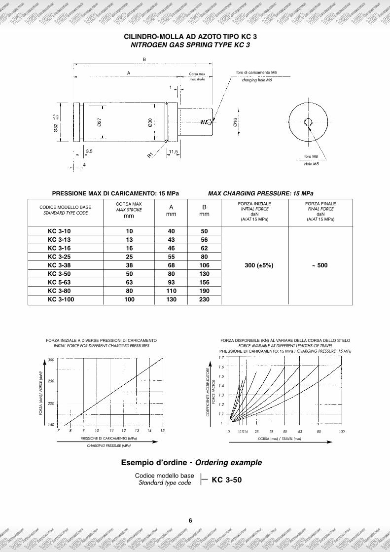
CILINDRO-MOLLA AD AZOTO TIPO KC 3NITROGEN GAS SPRING TYPE KC 3
Codice modello baseStandard type code
Esempio d’ordine - Ordering example
Corsa max
max stroke
R111,5
1
Ø30
Ø27
Ø16
4
3.5
Ø32
+0,
3-0
,3B
A foro di caricamento M6
charging hole M6
foro M8
Hole M8
KC 3-50
1.7
1.6
1.5
1.4
1.3
1.2
1.1
1
0 10 13 16 25 38 50 63 80 100
CO
EFFI
CIE
NTE
MO
LTIP
LICAT
ORE
FORC
E FA
CTO
R
CORSA (mm) / TRAVEL (mm)
FORZ
A (d
aN)/
FO
RCE
(daN
)
PRESSIONE DI CARICAMENTO (MPa)
CHARGING PRESSURE (MPa)
300
250
200
150
7 8 9 10 11 12 13 14 15
FORZA INIZIALE A DIVERSE PRESSIONI DI CARICAMENTOINITIAL FORCE FOR DIFFERENT CHARGING PRESSURES
FORZA DISPONIBILE (KN) AL VARIARE DELLA CORSA DELLO STELOFORCE AVAILABLE AT DIFFERENT LENGTHS OF TRAVEL
PRESSIONE DI CARICAMENTO: 15 MPa / CHARGING PRESSURE: 15 MPa
CODICE MODELLO BASESTANDARD TYPE CODE
KC 3-10 10 40 50KC 3-13 13 43 56KC 3-16 16 46 62KC 3-25 25 55 80KC 3-38 38 68 106 300 (±5%) ~ 500KC 3-50 50 80 130KC 5-63 63 93 156KC 3-80 80 110 190KC 3-100 100 130 230
CORSA MAXMAX STROKE
mmA
mmB
mm
FORZA INIZIALEINITIAL FORCE
daN(A/AT 15 MPa)
FORZA FINALEFINAL FORCE
daN(A/AT 15 MPa)
PRESSIONE MAX DI CARICAMENTO: 15 MPa MAX CHARGING PRESSURE: 15 MPa
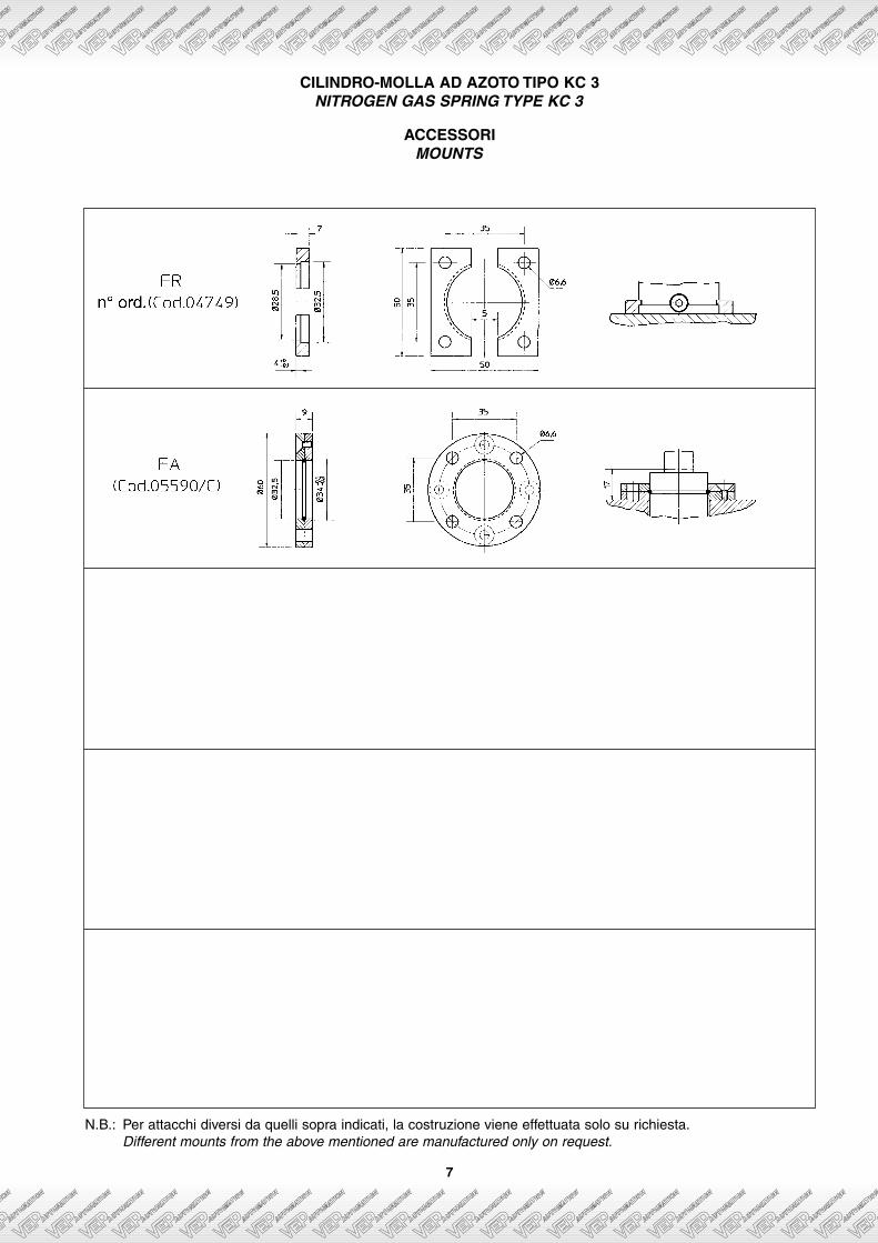
CILINDRO-MOLLA AD AZOTO TIPO KC 3NITROGEN GAS SPRING TYPE KC 3
7
ACCESSORIMOUNTS
N.B.: Per attacchi diversi da quelli sopra indicati, la costruzione viene effettuata solo su richiesta.Different mounts from the above mentioned are manufactured only on request.
8
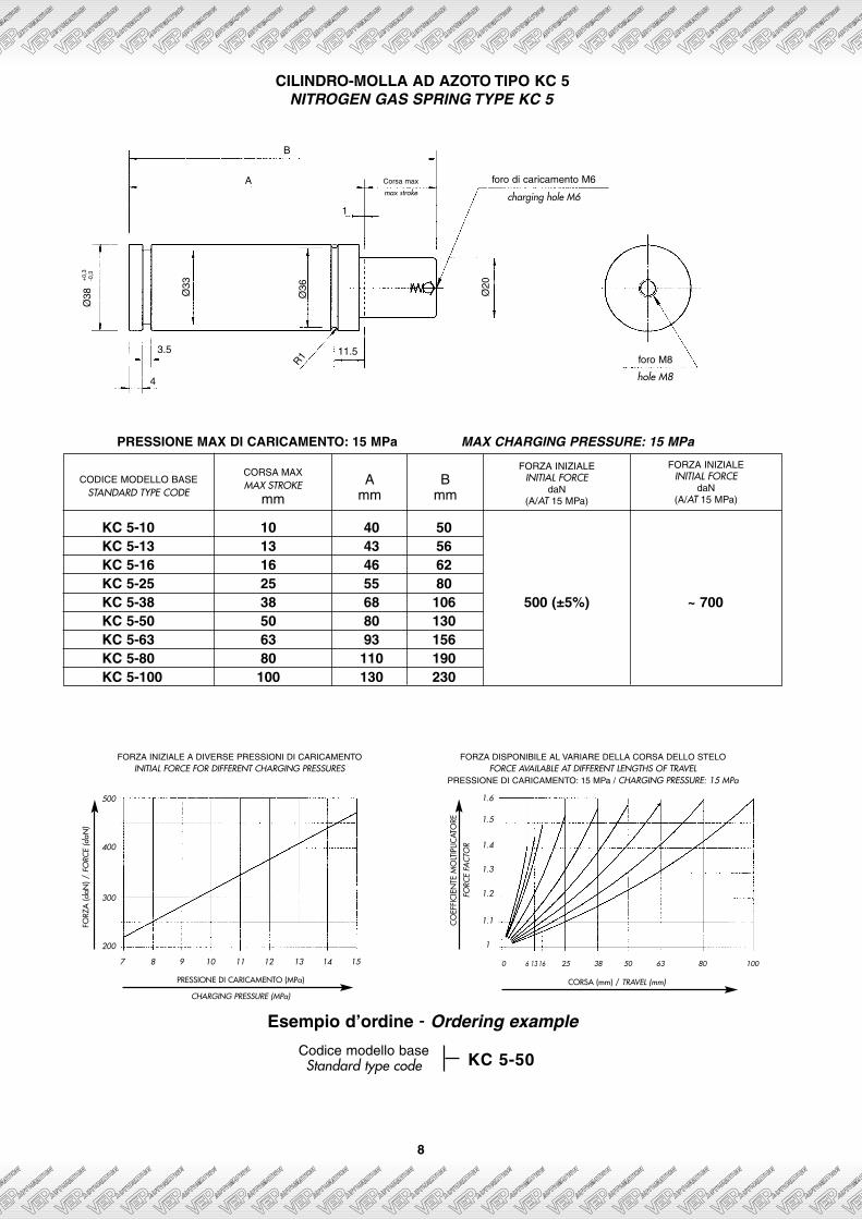
CILINDRO-MOLLA AD AZOTO TIPO KC 5NITROGEN GAS SPRING TYPE KC 5
CODICE MODELLO BASESTANDARD TYPE CODE
KC 5-10 10 40 50KC 5-13 13 43 56KC 5-16 16 46 62KC 5-25 25 55 80KC 5-38 38 68 106 500 (±5%) ~ 700KC 5-50 50 80 130KC 5-63 63 93 156KC 5-80 80 110 190KC 5-100 100 130 230
CORSA MAXMAX STROKE
mmA
mmB
mm
FORZA INIZIALEINITIAL FORCE
daN(A/AT 15 MPa)
FORZA INIZIALEINITIAL FORCE
daN(A/AT 15 MPa)
FORZA INIZIALE A DIVERSE PRESSIONI DI CARICAMENTOINITIAL FORCE FOR DIFFERENT CHARGING PRESSURES
FORZA DISPONIBILE AL VARIARE DELLA CORSA DELLO STELOFORCE AVAILABLE AT DIFFERENT LENGTHS OF TRAVEL
PRESSIONE DI CARICAMENTO: 15 MPa / CHARGING PRESSURE: 15 MPa
Ø20
Corsa max
max stroke
R1 11.5
1
Ø36Ø33
3.5
4
Ø38
+0,
3-0
,3
B
A foro di caricamento M6
charging hole M6
foro M8
hole M8
FORZ
A (d
aN) /
FO
RCE
(daN
)
PRESSIONE DI CARICAMENTO (MPa)
CHARGING PRESSURE (MPa)
500
400
300
200
7 8 9 10 11 12 13 14 15
1.6
1.5
1.4
1.3
1.2
1.1
1
0 6 13 16 25 38 50 63 80 100
CO
EFFI
CIE
NTE
MO
LTIP
LICAT
ORE
FORC
E FA
CTO
R
CORSA (mm) / TRAVEL (mm)
PRESSIONE MAX DI CARICAMENTO: 15 MPa MAX CHARGING PRESSURE: 15 MPa
Codice modello baseStandard type code
Esempio d’ordine - Ordering example
KC 5-50
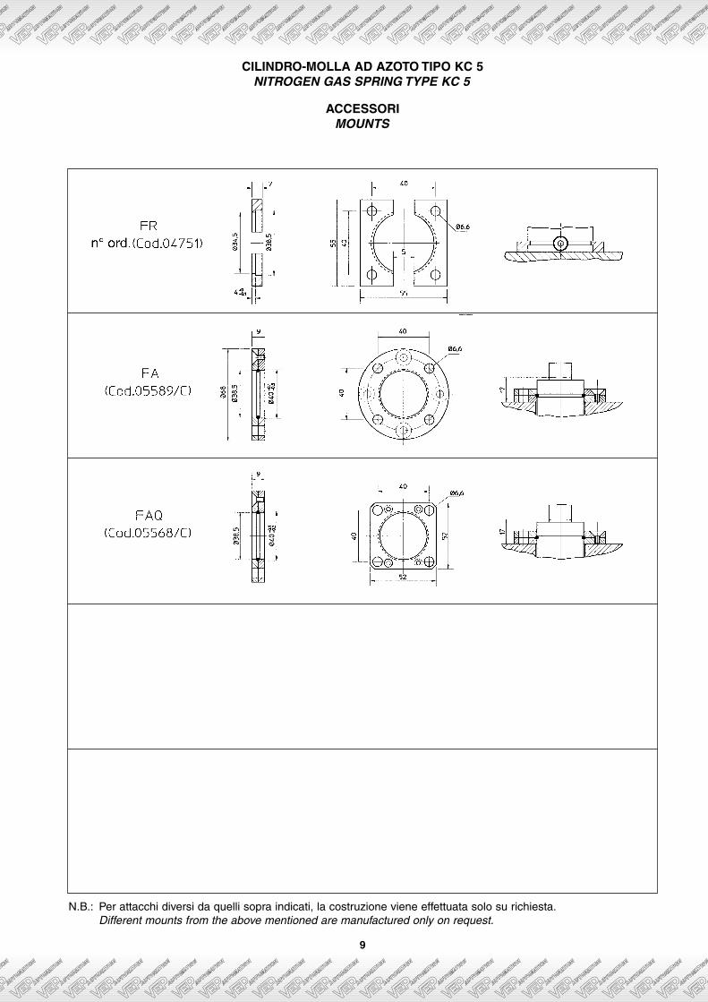
ACCESSORIMOUNTS
CILINDRO-MOLLA AD AZOTO TIPO KC 5NITROGEN GAS SPRING TYPE KC 5
9
N.B.: Per attacchi diversi da quelli sopra indicati, la costruzione viene effettuata solo su richiesta.Different mounts from the above mentioned are manufactured only on request.

10
CILINDRO-MOLLA AD AZOTO TIPO KC 7NITROGEN GAS SPRING TYPE KC 7
FORZA INIZIALE A DIVERSE PRESSIONI DI CARICAMENTOINITIAL FORCE FOR DIFFERENT CHARGING PRESSURES
FORZA DISPONIBILE AL VARIARE DELLA CORSA DELLO STELOFORCE AVAILABLE AT DIFFERENT LENGTHS OF TRAVEL
PRESSIONE DI CARICAMENTO: 15 MPa / CHARGING PRESSURE: 15 MPa
3.5 15.5R1
4
1
B
A
N°2 fori M8
N°2 holes M8
Ø43
Ø24 20Ø40
Corsa max
max stroke
foro di caricamento M6
charging hole M6
Ø45
+0,
3-0
,3
CODICE MODELLO BASESTANDARD TYPE CODE
KC 7-13 13 45 58KC 7-19 19 51 70KC 7-25 25 57 82KC 7-38 38 70 108KC 7-50 50 82 132 700 (±5%) ~ 1000KC 7-63 63 95 158KC 7-80 80 112 192KC 7-100 100 132 232KC 7-125 125 157 282
CORSA MAXMAX STROKE
mmA
mmB
mm
FORZA INIZIALEINITIAL FORCE
daN(A/AT 15 MPa)
FORZA INIZIALEINITIAL FORCE
daN(A/AT 15 MPa)
PRESSIONE MAX DI CARICAMENTO: 15 MPa MAX CHARGING PRESSURE: 15 MPa
FORZ
A (d
aN) /
FO
RCE
(daN
)
PRESSIONE DI CARICAMENTO (MPa)
CHARGING PRESSURE (MPa)
750
600
450
300
7 8 9 10 11 12 13 14 15
1.6
1.5
1.4
1.3
1.2
1.1
1
0 13 19 25 38 50 63 80 100 125
CO
EFFI
CIE
NTE
MO
LTIP
LICAT
ORE
FORC
E FA
CTO
R
CORSA (mm) / TRAVEL (mm)
Codice modello baseStandard type code
Per la versione collegabile vedi pag. 22For the no self-containing you see to pag. 22
Esempio d’ordine - Ordering example
KC 7-50
11
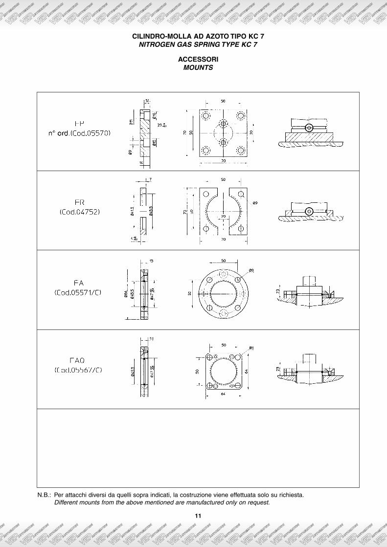
ACCESSORIMOUNTS
CILINDRO-MOLLA AD AZOTO TIPO KC 7NITROGEN GAS SPRING TYPE KC 7
N.B.: Per attacchi diversi da quelli sopra indicati, la costruzione viene effettuata solo su richiesta.Different mounts from the above mentioned are manufactured only on request.
12
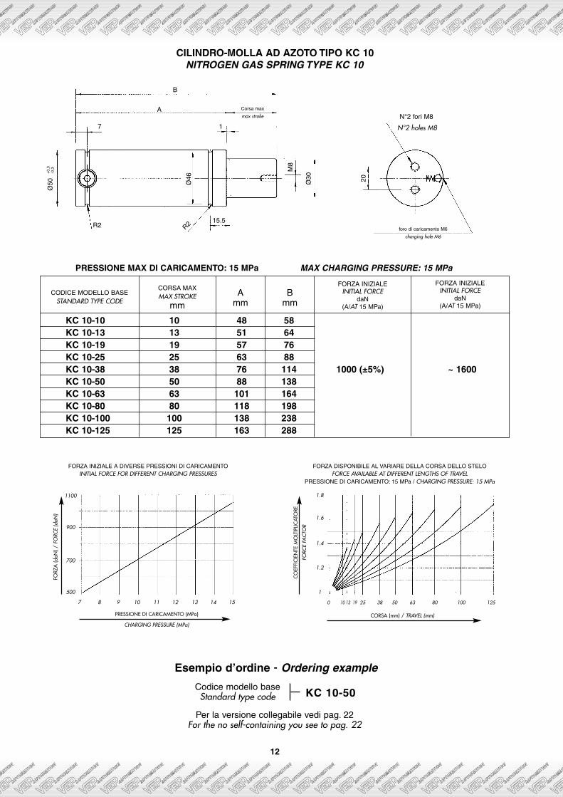
CILINDRO-MOLLA AD AZOTO TIPO KC 10NITROGEN GAS SPRING TYPE KC 10
FORZA INIZIALE A DIVERSE PRESSIONI DI CARICAMENTOINITIAL FORCE FOR DIFFERENT CHARGING PRESSURES
FORZA DISPONIBILE AL VARIARE DELLA CORSA DELLO STELOFORCE AVAILABLE AT DIFFERENT LENGTHS OF TRAVEL
PRESSIONE DI CARICAMENTO: 15 MPa / CHARGING PRESSURE: 15 MPa
R2
7 1
15.5R2
B
AN°2 fori M8
N°2 holes M8
Ø46
Ø30
M8
20
Corsa max
max stroke
foro di caricamento M6
charging hole M6
Ø50
+0,
3-0
,3
CODICE MODELLO BASESTANDARD TYPE CODE
KC 10-10 10 48 58KC 10-13 13 51 64KC 10-19 19 57 76KC 10-25 25 63 88KC 10-38 38 76 114 1000 (±5%) ~ 1600KC 10-50 50 88 138KC 10-63 63 101 164KC 10-80 80 118 198KC 10-100 100 138 238KC 10-125 125 163 288
CORSA MAXMAX STROKE
mmA
mmB
mm
FORZA INIZIALEINITIAL FORCE
daN(A/AT 15 MPa)
FORZA INIZIALEINITIAL FORCE
daN(A/AT 15 MPa)
PRESSIONE MAX DI CARICAMENTO: 15 MPa MAX CHARGING PRESSURE: 15 MPa
FORZ
A (d
aN) /
FO
RCE
(daN
)
PRESSIONE DI CARICAMENTO (MPa)
CHARGING PRESSURE (MPa)
1100
900
700
500
7 8 9 10 11 12 13 14 15
1.8
1.6
1.4
1.2
1
0 10 13 19 25 38 50 63 80 100 125
CO
EFFI
CIE
NTE
MO
LTIP
LICAT
ORE
FORC
E FA
CTO
R
CORSA (mm) / TRAVEL (mm)
Codice modello baseStandard type code
Per la versione collegabile vedi pag. 22For the no self-containing you see to pag. 22
Esempio d’ordine - Ordering example
KC 10-50
13
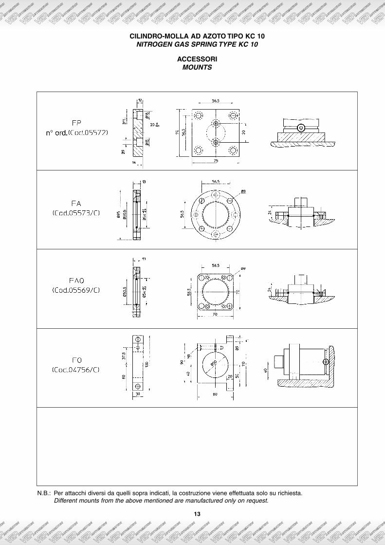
ACCESSORIMOUNTS
CILINDRO-MOLLA AD AZOTO TIPO KC 10NITROGEN GAS SPRING TYPE KC 10
N.B.: Per attacchi diversi da quelli sopra indicati, la costruzione viene effettuata solo su richiesta.Different mounts from the above mentioned are manufactured only on request.
14
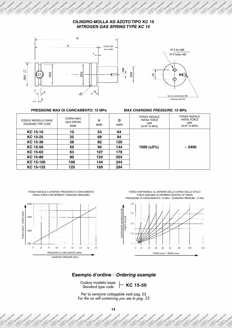
CILINDRO-MOLLA AD AZOTO TIPO KC 15NITROGEN GAS SPRING TYPE KC 15
FORZA INIZIALE A DIVERSE PRESSIONI DI CARICAMENTOINITIAL FORCE FOR DIFFERENT CHARGING PRESSURES
FORZA DISPONIBILE AL VARIARE DELLA CORSA DELLO STELOFORCE AVAILABLE AT DIFFERENT LENGTHS OF TRAVEL
PRESSIONE DI CARICAMENTO: 15 MPa / CHARGING PRESSURE: 15 MPa
5
8
1
19R2
B
A
N°2 fori M8
N°2 holes M8
Ø59
Ø56
Ø36
M8
20
Corsa max
max stroke
foro di caricamento M6
charging hole M6
Ø63
+0,
3-0
,3
CODICE MODELLO BASESTANDARD TYPE CODE
KC 15-10 10 54 64KC 15-25 25 69 94KC 15-38 38 82 120KC 15-50 50 94 144 1500 (±5%) ~ 2400KC 15-63 63 107 170KC 15-80 80 124 204KC 15-100 100 144 244KC 15-125 125 169 294
CORSA MAXMAX STROKE
mmA
mmB
mm
FORZA INIZIALEINITIAL FORCE
daN(A/AT 15 MPa)
FORZA INIZIALEINITIAL FORCE
daN(A/AT 15 MPa)
PRESSIONE MAX DI CARICAMENTO: 15 MPa MAX CHARGING PRESSURE: 15 MPa
FORZ
A (d
aN) /
FO
RCE
(daN
)
PRESSIONE DI CARICAMENTO (MPa)
CHARGING PRESSURE (MPa)
1600
1300
1000
700
7 8 9 10 11 12 13 14 15
1.8
1.6
1.4
1.2
1
0 10 25 38 50 63 80 100 125
CO
EFFI
CIE
NTE
MO
LTIP
LICAT
ORE
FORC
E FA
CTO
R
CORSA (mm) / TRAVEL (mm)
Codice modello baseStandard type code
Per la versione collegabile vedi pag. 23For the no self-containing you see to pag. 23
Esempio d’ordine - Ordering example
KC 15-50
15
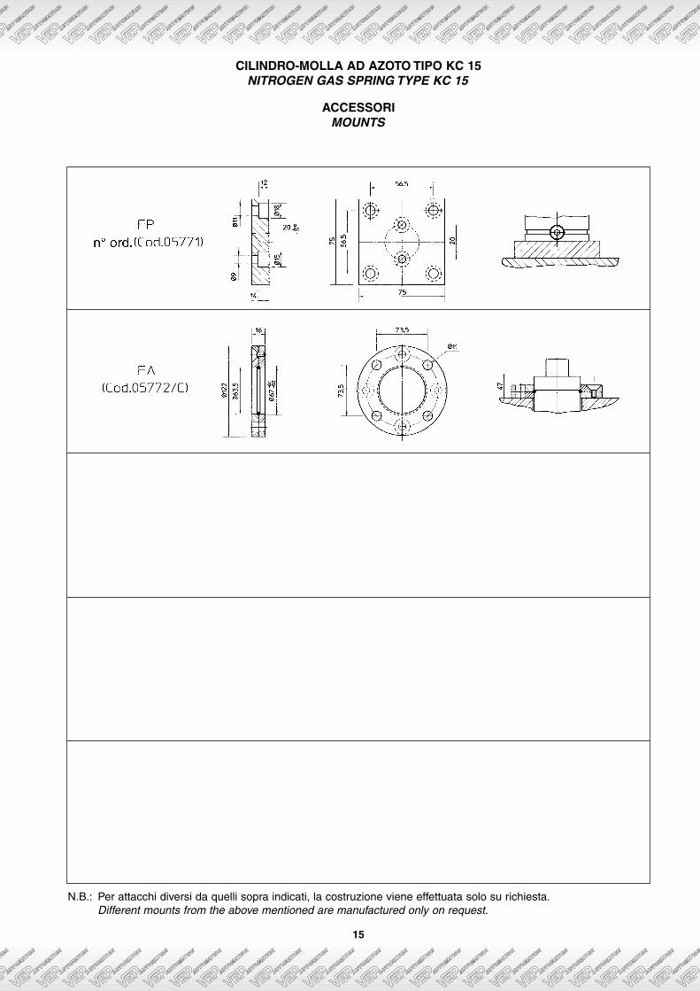
CILINDRO-MOLLA AD AZOTO TIPO KC 15NITROGEN GAS SPRING TYPE KC 15
N.B.: Per attacchi diversi da quelli sopra indicati, la costruzione viene effettuata solo su richiesta.Different mounts from the above mentioned are manufactured only on request.
ACCESSORIMOUNTS
16
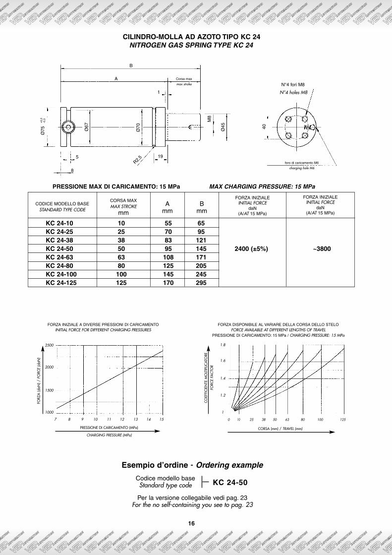
CILINDRO-MOLLA AD AZOTO TIPO KC 24NITROGEN GAS SPRING TYPE KC 24
FORZA INIZIALE A DIVERSE PRESSIONI DI CARICAMENTOINITIAL FORCE FOR DIFFERENT CHARGING PRESSURES
FORZA DISPONIBILE AL VARIARE DELLA CORSA DELLO STELOFORCE AVAILABLE AT DIFFERENT LENGTHS OF TRAVEL
PRESSIONE DI CARICAMENTO: 15 MPa / CHARGING PRESSURE: 15 MPa
5
8
1
19R2,
5
B
AN°4 fori M8
N°4 holes M8
Ø70
Ø67
Ø45
M8
40
Corsa max
max stroke
foro di caricamento M6
charging hole M6
Ø75
+0,
3-0
,3
CODICE MODELLO BASESTANDARD TYPE CODE
KC 24-10 10 55 65KC 24-25 25 70 95KC 24-38 38 83 121KC 24-50 50 95 145 2400 (±5%) ~3800KC 24-63 63 108 171KC 24-80 80 125 205KC 24-100 100 145 245KC 24-125 125 170 295
CORSA MAXMAX STROKE
mmA
mmB
mm
FORZA INIZIALEINITIAL FORCE
daN(A/AT 15 MPa)
FORZA INIZIALEINITIAL FORCE
daN(A/AT 15 MPa)
PRESSIONE MAX DI CARICAMENTO: 15 MPa MAX CHARGING PRESSURE: 15 MPa
FORZ
A (d
aN) /
FO
RCE
(daN
)
PRESSIONE DI CARICAMENTO (MPa)
CHARGING PRESSURE (MPa)
2500
2000
1500
1000
7 8 9 10 11 12 13 14 15
1.8
1.6
1.4
1.2
1
0 10 25 38 50 63 80 100 125
CO
EFFI
CIE
NTE
MO
LTIP
LICAT
ORE
FORC
E FA
CTO
R
CORSA (mm) / TRAVEL (mm)
Codice modello baseStandard type code
Per la versione collegabile vedi pag. 23For the no self-containing you see to pag. 23
Esempio d’ordine - Ordering example
KC 24-50
17
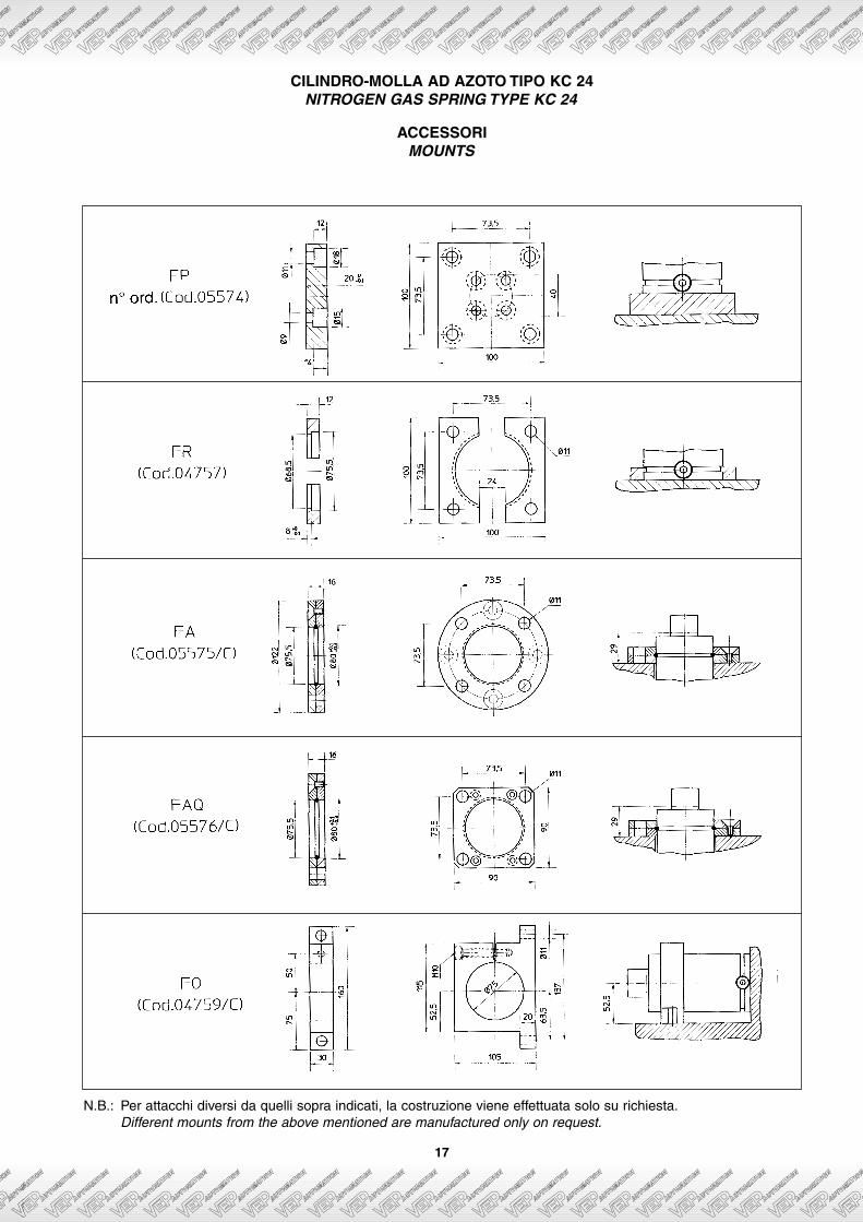
CILINDRO-MOLLA AD AZOTO TIPO KC 24NITROGEN GAS SPRING TYPE KC 24
N.B.: Per attacchi diversi da quelli sopra indicati, la costruzione viene effettuata solo su richiesta.Different mounts from the above mentioned are manufactured only on request.
ACCESSORIMOUNTS

18
CILINDRO-MOLLA AD AZOTO TIPO KC 42NITROGEN GAS SPRING TYPE KC 42
FORZA INIZIALE A DIVERSE PRESSIONI DI CARICAMENTOINITIAL FORCE FOR DIFFERENT CHARGING PRESSURES
FORZA DISPONIBILE AL VARIARE DELLA CORSA DELLO STELOFORCE AVAILABLE AT DIFFERENT LENGTHS OF TRAVEL
PRESSIONE DI CARICAMENTO: 15 MPa / CHARGING PRESSURE: 15 MPa
5
8
1
22
R2,5
B
A
N°4 fori M8
N°4 holes M8
Ø90
Ø87
Ø60
M8
60
Corsa max
max stroke
foro di caricamento M6
charging hole M6
Ø95
+0,
3-0
,3
CODICE MODELLO BASESTANDARD TYPE CODE
KC 42-25 25 90 115KC 42-38 38 103 141KC 42-50 50 115 165KC 42-63 63 128 191 4200 (±5%) ~6400KC 42-80 80 145 225KC 42-100 100 165 265KC 42-125 125 190 315
CORSA MAXMAX STROKE
mmA
mmB
mm
FORZA INIZIALEINITIAL FORCE
daN(A/AT 15 MPa)
FORZA INIZIALEINITIAL FORCE
daN(A/AT 15 MPa)
PRESSIONE MAX DI CARICAMENTO: 15 MPa MAX CHARGING PRESSURE: 15 MPa
FORZ
A (d
aN) /
FO
RCE
(daN
)
PRESSIONE DI CARICAMENTO (MPa)
CHARGING PRESSURE (MPa)
4300
3500
2700
1900
7 8 9 10 11 12 13 14 15
1.7
1.6
1.5
1.4
1.3
1.2
1.1
10 25 38 50 63 80 100 125
CO
EFFI
CIE
NTE
MO
LTIP
LICAT
ORE
FORC
E FA
CTO
R
CORSA (mm) / TRAVEL (mm)
Codice modello baseStandard type code
Per la versione collegabile vedi pag. 23For the no self-containing you see to pag. 23
Esempio d’ordine - Ordering example
KC 42-50

19
CILINDRO-MOLLA AD AZOTO TIPO KC 42NITROGEN GAS SPRING TYPE KC 42
N.B.: Per attacchi diversi da quelli sopra indicati, la costruzione viene effettuata solo su richiesta.Different mounts from the above mentioned are manufactured only on request.
ACCESSORIMOUNTS

20
CILINDRO-MOLLA AD AZOTO TIPO KC 66NITROGEN GAS SPRING TYPE KC 66
FORZA INIZIALE A DIVERSE PRESSIONI DI CARICAMENTOINITIAL FORCE FOR DIFFERENT CHARGING PRESSURES
FORZA DISPONIBILE AL VARIARE DELLA CORSA DELLO STELOFORCE AVAILABLE AT DIFFERENT LENGTHS OF TRAVEL
PRESSIONE DI CARICAMENTO: 15 MPa / CHARGING PRESSURE: 15 MPa
5
8
1
23.5R2,
5
B
A
10
N°4 fori M10
N°4 holes M10
Ø11
5
Ø11
2
Ø75
M8
80
Corsa max
max stroke
foro di caricamento G1/8”
charging hole G1/8”
Ø12
0+
0,3
-0,3
FORZ
A (d
aN) /
FO
RCE
(daN
)
PRESSIONE DI CARICAMENTO (MPa)
CHARGING PRESSURE (MPa)
6600
5400
4200
3000
7 8 9 10 11 12 13 14 15
1.7
1.6
1.5
1.4
1.3
1.2
1.1
10 25 38 50 63 80 100 125
CO
EFFI
CIE
NTE
MO
LTIP
LICAT
ORE
FORC
E FA
CTO
R
CORSA (mm) / TRAVEL (mm)
Codice modello baseStandard type code
Esempio d’ordine - Ordering example
KC 66-50
CODICE MODELLO BASESTANDARD TYPE CODE
N.B: IL CILINDRO KC 66 VIENE COSTRUITO SOLO SU RICHIESTATHE SPRING KC 66 IS MANUFACTURED ONLY ON REQUEST
KC 66-25 25 100 125 345KC 66-38 38 113 151 470KC 66-50 50 125 175 590KC 66-63 63 138 201 6600 (±5%) ~11000 710KC 66-80 80 155 235 870KC 66-100 100 175 275 1060KC 66-125 125 200 325 1300
CORSA MAXMAX STROKE
mmA
mmB
mm
FORZA INIZIALEINITIAL FORCE
daN(A/AT 15 MPa)
FORZA FINALEFINAL FORCE
daN(A/AT 15 MPa)
VOLUME INIZIALEINITIAL VOLUME
Vo = cm3
PRESSIONE MAX DI CARICAMENTO: 15 MPa MAX CHARGING PRESSURE: 15 MPa
21
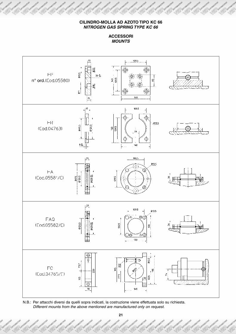
CILINDRO-MOLLA AD AZOTO TIPO KC 66NITROGEN GAS SPRING TYPE KC 66
N.B.: Per attacchi diversi da quelli sopra indicati, la costruzione viene effettuata solo su richiesta.Different mounts from the above mentioned are manufactured only on request.
ACCESSORIMOUNTS
22
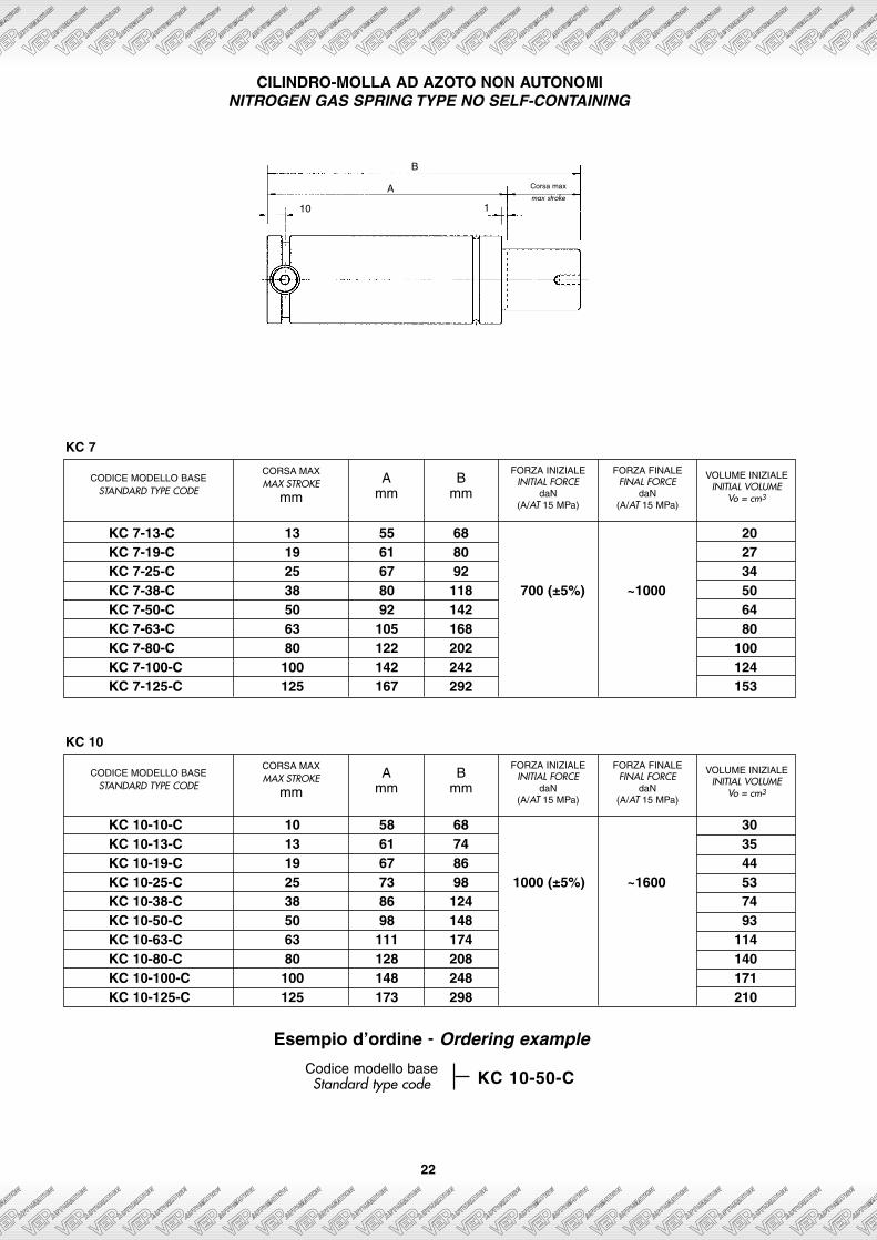
CILINDRO-MOLLA AD AZOTO NON AUTONOMINITROGEN GAS SPRING TYPE NO SELF-CONTAINING
CODICE MODELLO BASESTANDARD TYPE CODE
KC 7-13-C 13 55 68 20KC 7-19-C 19 61 80 27KC 7-25-C 25 67 92 34KC 7-38-C 38 80 118 700 (±5%) ~1000 50KC 7-50-C 50 92 142 64KC 7-63-C 63 105 168 80KC 7-80-C 80 122 202 100KC 7-100-C 100 142 242 124KC 7-125-C 125 167 292 153
CORSA MAXMAX STROKE
mmA
mmB
mm
FORZA INIZIALEINITIAL FORCE
daN(A/AT 15 MPa)
FORZA FINALEFINAL FORCE
daN(A/AT 15 MPa)
VOLUME INIZIALEINITIAL VOLUME
Vo = cm3
KC 7
CODICE MODELLO BASESTANDARD TYPE CODE
KC 10-10-C 10 58 68 30KC 10-13-C 13 61 74 35KC 10-19-C 19 67 86 44KC 10-25-C 25 73 98 1000 (±5%) ~1600 53KC 10-38-C 38 86 124 74KC 10-50-C 50 98 148 93KC 10-63-C 63 111 174 114KC 10-80-C 80 128 208 140KC 10-100-C 100 148 248 171KC 10-125-C 125 173 298 210
CORSA MAXMAX STROKE
mmA
mmB
mm
FORZA INIZIALEINITIAL FORCE
daN(A/AT 15 MPa)
FORZA FINALEFINAL FORCE
daN(A/AT 15 MPa)
VOLUME INIZIALEINITIAL VOLUME
Vo = cm3
KC 10
Codice modello baseStandard type code
Esempio d’ordine - Ordering example
KC 10-50-C
A
10 1
B
Corsa max
max stroke
23
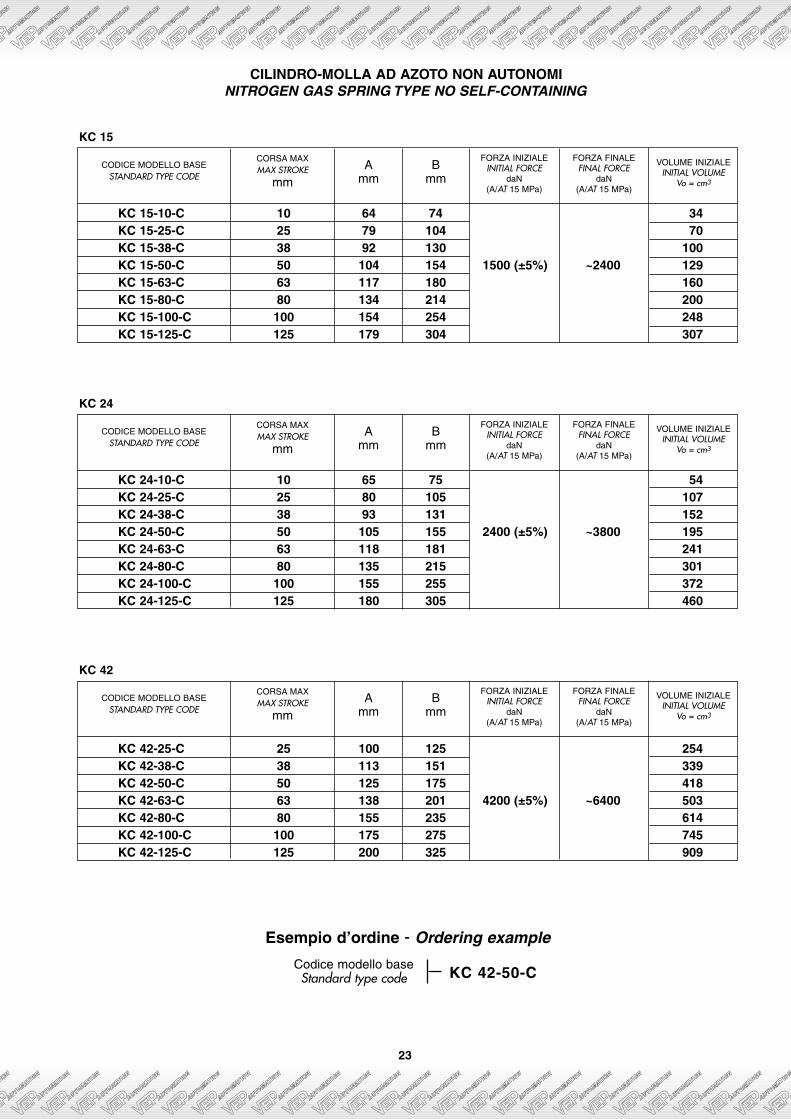
CILINDRO-MOLLA AD AZOTO NON AUTONOMINITROGEN GAS SPRING TYPE NO SELF-CONTAINING
CODICE MODELLO BASESTANDARD TYPE CODE
KC 15-10-C 10 64 74 34KC 15-25-C 25 79 104 70KC 15-38-C 38 92 130 100KC 15-50-C 50 104 154 1500 (±5%) ~2400 129KC 15-63-C 63 117 180 160KC 15-80-C 80 134 214 200KC 15-100-C 100 154 254 248KC 15-125-C 125 179 304 307
CORSA MAXMAX STROKE
mmA
mmB
mm
FORZA INIZIALEINITIAL FORCE
daN(A/AT 15 MPa)
FORZA FINALEFINAL FORCE
daN(A/AT 15 MPa)
VOLUME INIZIALEINITIAL VOLUME
Vo = cm3
KC 15
CODICE MODELLO BASESTANDARD TYPE CODE
KC 24-10-C 10 65 75 54KC 24-25-C 25 80 105 107KC 24-38-C 38 93 131 152KC 24-50-C 50 105 155 2400 (±5%) ~3800 195KC 24-63-C 63 118 181 241KC 24-80-C 80 135 215 301KC 24-100-C 100 155 255 372KC 24-125-C 125 180 305 460
CORSA MAXMAX STROKE
mmA
mmB
mm
FORZA INIZIALEINITIAL FORCE
daN(A/AT 15 MPa)
FORZA FINALEFINAL FORCE
daN(A/AT 15 MPa)
VOLUME INIZIALEINITIAL VOLUME
Vo = cm3
KC 24
CODICE MODELLO BASESTANDARD TYPE CODE
KC 42-25-C 25 100 125 254KC 42-38-C 38 113 151 339KC 42-50-C 50 125 175 418KC 42-63-C 63 138 201 4200 (±5%) ~6400 503KC 42-80-C 80 155 235 614KC 42-100-C 100 175 275 745KC 42-125-C 125 200 325 909
CORSA MAXMAX STROKE
mmA
mmB
mm
FORZA INIZIALEINITIAL FORCE
daN(A/AT 15 MPa)
FORZA FINALEFINAL FORCE
daN(A/AT 15 MPa)
VOLUME INIZIALEINITIAL VOLUME
Vo = cm3
KC 42
Codice modello baseStandard type code
Esempio d’ordine - Ordering example
KC 42-50-C


![[IMPORTANTE] Scattare fotografie CARATTERISTICHE ...instax.fujifilm.it/manuali/Instax-Mini-9.pdf · CPL10B112-100 Nomenclatura delle parti 1 Slot espulsione pellicola 11 Ghiera regolazione](https://static.fdocumenti.com/doc/165x107/5f9d2f70d3736f33ad4bb0e4/importante-scattare-fotografie-caratteristiche-cpl10b112-100-nomenclatura.jpg)