CATALOGUE 2021 - Cordivari
24
A A B 0° 30° 315 93 60° 60° 45° 34 570 300 1100 150 SN 3 I.O. 14 1 1 2 2 3 3 5 1 6 1 7 1 4 1 1 4 1 4 1 30° 60° 45° SN 2 PRESSURIZED WATER TANKS AND COMPRESSED AIR RECEIVERS CATALOGUE 2021
Transcript of CATALOGUE 2021 - Cordivari
A
A
BB
8
7
A
6
5
B C D
4
3
2
1
A2 A B C D
E F G H
8
7
6
5
E F
4
3
2
G H
1
La Cordivari S.r.l. si riseva di apportare variazioni costruttive, migliorative del prodotto senza preavviso.
>1,5
S1 S22+3XS2
>1,5xS2
45
S3 >=0.3xS3+1.5
S1÷S
2
45
S3
S1÷S
2
>=0.3xS3+1.5
4
4
R169.2
R880
30° 30°
5.2
9
10
4.953.
63
444
2545
315
93
90°
60°60°
45°
45°
45°
5.19
70
2" G
as(6
0)34
570
300
70
50
50
2" Gas(60)
33.7
25
3/4"
Gas
(26)
26.9
15
3/8"
Gas
(17)
1100
1750
150
150
1250
1050
- Attestato secondo EN 10204 tipo 2.1 2054172010633
PARTICOLARI SALDATURESN
PRO
CED
IMEN
TOSA
LDAT
UR
E
1 3
PRO
CED
IMEN
TI D
I SAL
DAT
UR
AAU
TOM
ATIC
I QU
ALIF
ICAT
IW
PS V
EDI P
ARTI
CO
LAR
E
WPS 01/11 - PROC.121 (S2<=12 mm)
2
PRO
CED
IMEN
TI D
I SAL
DAT
UR
AQ
UAL
IFIC
ATI S
ECO
ND
OW
PS V
EDI P
ARTI
CO
LAR
E
5
4
PRO
CED
IMEN
TI D
I SAL
DAT
UR
ASE
MIA
UTO
M.Q
UAL
IFIC
.SEC
ON
DO
WPS
VED
I PAR
TIC
OLA
RE
WPS 16/08 - >= 25,00 PROC. 136WPS 18/08 - >= 30,15 PROC. 135
(>= 3 <=16)
PRO
CED
IMEN
TI D
I SAL
DAT
UR
AQ
UAL
IFIC
ATA
SEC
ON
DO
WPS
VED
I PAR
TIC
OLA
RE
WPS 17/08- >=25,00 EST.SEMIAUTOM.PR.136/INT.SEMIAUTOM.PR.136WPS 19/08- >=25,00 EST.SEMIAUTOM.PR.135/INT.SEMIAUTOM.PR.135WPS 20/08- >=25,00 EST.SEMIAUTOM.PR.135/INT.MAN.PR.111
(>= 3 <=16)
1÷1.5
S1
Barra di CU
S1
Cordivari 5/94 - PROC.121 (S1<=6 mm)
SN 1
SN 3
I.O. 14
SEZIONE A-A
SN 2
SN 2
I.O.14
SEZIONE A-ASCALA 1:2
SN 5
SEZIONE B-BSCALA 1:2
SN 5
SEZIONE A-ASCALA 1:2
SN 4
SEZIONE A-ASCALA 1:2
SN 4
VISTA VSCALA 1:5
I.O.14
11
22
33
51
61
71
41
41
41
41
41
82
92
41
4RIF
4RIF
5RIF
6RIF
30° 30°
90°
60°60°
45°
45°
45°SN 2
I.O.14
PRESSURIZED WATER TANKS AND
COMPRESSED AIR RECEIVERS
CATALOGUE 2021
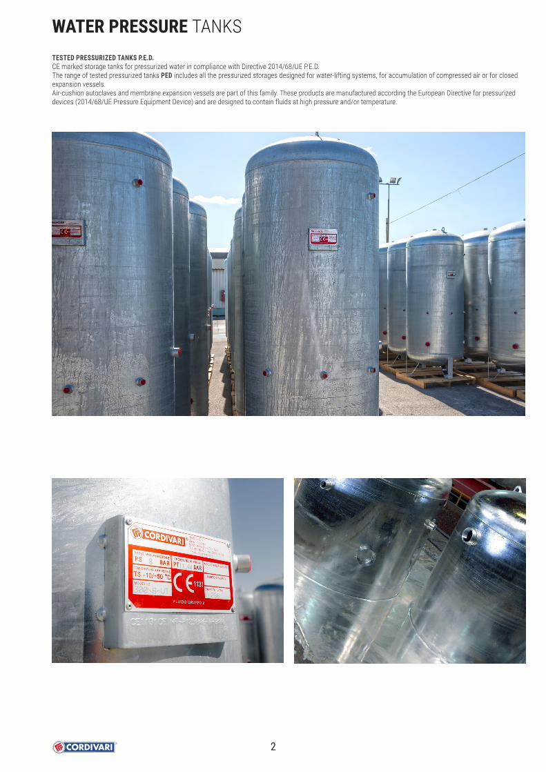
WATER PRESSURE TANKSTESTED PRESSURIZED TANKS P.E.D.CE marked storage tanks for pressurized water in compliance with Directive 2014/68/UE P.E.D.The range of tested pressurized tanks PED includes all the pressurized storages designed for water-lifting systems, for accumulation of compressed air or for closed expansion vessels.Air-cushion autoclaves and membrane expansion vessels are part of this family. These products are manufactured according the European Directive for pressurized devices (2014/68/UE Pressure Equipment Device) and are designed to contain fluids at high pressure and/or temperature.
2

THE PRESSURE EQUIPMENT DEVICE (P.E.D.) DIRECTIVEAny device that overcomes the maximum working pressure limit of 0,5 BAR is subject to design and manufacture indications according to the directive 2014/68/EU.
This directive establishes an index of hazardousness of the equipment (tanks in our case), determined according to the type of fluid contained, the maximum temperature admissible, the pressure and the capacity of the tank.
Fluids are categorized in 2 groups:• GROUP 1, hazardous fluids (explosive, flammable, easily flammable, highly flammable, oxidizer, toxic and highly toxic)• GROUP 2, not hazardous fluids (all fluids which are not included in GROUP 1)
Note: all the Cordivari products involved in the application of the PED directive are intended to contain fluids belonging to GROUP 2 (water, steam, compressed air).The categorization of the equipment in accordance with the level of hazardousness is established in the Annex II of the directive that defines six classes:
USE OF PRESSURE EQUIPMENT ACCORDING TO ITALIAN LAWS AND REGULATIONSThe use of pressure equipment is regulated in Italy by Ministerial Decree No. 329/2004. This decree establishes requirements for the correct operation of pressure equipments both during installation and start-up and in terms of subsequent periodic checks. On this regard, following activities are defined: • DECLARATION OF COMMISSIONING: Is intended the declaration to be submitted to National Labour Security Institute and to the competent for the territory
Sanitary Office, containing the following annexes according to the provisions of art. 6.1 of Ministerial Decree no. 329/2004.• FIRST INSTALLATION COMMISSIONING: control consisting in verifying by competent approved body (Labour or Medical Institute) that the tank has been correctly
installed in compliance with user manual and maintenance issued by the manufacturer of the equipment and in compliance with the local laws in force.• PERIODICAL RE-QUALIFICATION: compulsory periodic checks to be carried out by authorised bodies on pressure equipments in service under responisibility of
user, in order to check the compliance for a continuous operation.• OPERATION CHECK: performed to assess the compliance of the actual conditions of use of the equipment with what is reported in the declaration of
commissioning and in manual. During this phase, the safety accessories are also subjected to a functional check.• INTEGRITY CHECK: this is carried out through a visual examination both inside and outside the pressure equipment and through instrumental checks that
determine whether the equipment is still within the limits set by the manufacturer, e.g. by checking the thickness.
DECREE 329 states exclusions cases (total or partial) from the operational checks, according to following scheme.
Category Application of the PED directive CE Marking Reference
PS ≤ 0,5 and specific exceptions Not applicable No Art. 1.1 and 1.2
PS ≥ 0,5 in conditions of low hazard level Applicable No Art. 4.3
Category I Applicable Yes
Table from 1 to 9 Annex II
Category II Applicable Yes
Category III Applicable Yes
Category IV Applicable Yes
WATER PRESSURE TANKS
CAPACITYV [litri]
MAXIMUM OPERATING PRESSURE
PS [bar]
PS x V[bar x litre]
POTENTIAL CORROSION
INTERNAL OR EXTERNAL (*)
DECLARATION OF COMMISSIONING
COMMISSIONINGCHECK
PERIODICREQUALIFICATION
≤ 25 whatever − − No NoNo (**)25 < V ≤ 50 ≤ 12 − − No No
> 50≤ 12 ≤ 8000 No Yes No≤ 12 ≤ 8000 Yes Yes No Yes (***)≤ 12 ≤ 12000 No Yes Yes No (**)
(*) The absence of corrosive phenomena inside or outside the equipments can be declared by the designer in the declaration of commissioning only for fluid under Group 2 , except steam.
(**) The user must always follow the instructions in the operating and maintenance manual.
(***) Always to be carried out by an approved body.Categories I and II Functional check Four-yearly - Integrity check Ten-yearly Categories III and IV Operation check Every four years - Integrity check: Every ten years
We recommend always to check the national laws in force at place of installation for the use of pressure equipment.
3

APPLICATION AND TECHNICAL DESCRIPTIONAir cushion pressure vessels.Suitable to supply water to the highest floors of the buildings and to compensate the water shortage of the water-works. The air cushion pressure vessels Z PED VT are made for water pumping and they work as a pressured water lung that, if correctly dimensioned, can limit the self-starting of the pump.These products are made in galvanized mild steel.ANTI-CORROSION TREATMENTThese tanks are galvanized inside and outside, with immersion in a pool of fused zinc with pureness not below than 99,99% (Uni EN 1179)DOCUMENTS ATTACHED• CE certification• User Instructions
CERTIFICATIONSThe Z PED VT pressure vessels are made according to the security policy of the standard 2014/68/UE that rules the pressurized products. Under surveillance of the Notified Body, a CE mark is stuck on them as well as the following project data that characterize the product:• Pressurized fluid: water + air or nitrogen• Fluid group: 2• Max operating pressure: see the table chart• Temperature: -10/+50 °CWARRANTY2 years-See general sales conditions and warranty.
ModelAUTOCL. Z VT Max
Pressure
Art. Nr. [Bar]100 3052171990001
8
200 3052171990022300 3052171990003500 3052171990004750 3052171990025
1000 30521719900261500 30511719900152000 30511719900162500 30511719900173000 30511719900684000 3051171990019
5000 ø1450 30511719900208000 3051172020021
10000 3051172020022
ModelAUTOCL. Z VT
WITH MANHOLDMax
Pressure
Art. Nr. [Bar]5000 ø1600 3051172020007
88000 305117202001110000 3051172020012
ModelAUTOCL. Z VT
WITH MANHOLDMax
Pressure
Art. Nr. [Bar]4000 3051172020008
125000 ø1450 30511720200048000 3051172020013
10000 3051172020014
Models from 100 to 1000 are provided with safety valve and pressure gauge.
ON REQUEST:Insulation version with elastolen 20 mm – anti-condensation
ModelAUTOCL. Z VT Max
Pressure
Art. Nr. [Bar]100 3052171990015
11,76200 3051171990074300 3051171990025500 3051171990026750 3051171990077
12
1000 30511719900781500 30511719900292000 30511719900302500 30511719900313000 30511719900824000 3051171990033
5000 ø1450 30511719900358000 3051172020018
10000 3051172020019Models from 100 and 500 are provided with safety valve and pressure gauge.
Pumpflowrate[litres/1’]
CENTER
CITY
Facilities with 1
bathroom
Facilities with 2
bathrooms
Facilities with 3
bathrooms
250
200
1500
1000
500
300
200
150
100
50
25
5 10 15 20 25 30 35 40
5
2
10
10
15
15
2030
Pressure vesselmodel
To quickly determine both the capacity of the pressure vessel and the pump according to the number of the flats, you can use the following chart (always valid for 15 self-starting):
PRESSURE TEMPERATURE
Pmax Tmax[see table chart] -10 / +50 °C
AUTOCLAVE ZINCATA Z PED VTCertified vertical galvanized pressure vessel (standard 2014/68/UE)
STOCK AVAILABILITY
4

Model De H R1 H1 H2 H3 H4 H5 H6 O-A F H B-C D G
[mm] Connections F
WOR
KING
PRE
SSUR
E
8 b
ar
100 400 1055 1065 90 350 500 600 800 - 1"1/4 1" - 1/2” 1"1/4 -200 450 1420 1435 85 355 655 755 1155 - 1"1/4 1" - 1/2” 1"1/4 -300 550 1530 1555 140 435 735 835 1235 - 1"1/4 1"1/4 - 1/2” 1"1/4 -500 650 1825 1840 135 455 855 955 1505 - 1"1/4 1"1/2 - 1/2” 1"1/4 -750 790 1865 1880 110 510 960 1060 1460 - 1"1/4 1"1/2 - 1/2” 1"1/4 -
1000 790 2380 2395 110 510 1010 1110 1960 - 1"1/4 1"1/2 - 1/2” 1"1/4 -1500 950 2470 2490 110 570 1070 1170 2020 - 2" 2” - 1/2” 1"1/4 -2000 1100 2535 2560 100 595 1095 1195 2045 - 2" 2” - 1/2” 1"1/4 -2500 1200 2660 2690 140 680 1280 1380 2130 - 2" 3” - 1/2” 1"1/4 -3000 1200 3000 3075 135 700 1300 1400 2400 - 2" 3" - 1/2” 2” -4000 1450 3000 3030 115 710 1310 1410 2410 - 2" 3" 2" 1/2” 2" -5000 1450 3500 3525 115 710 1610 1710 2910 - 2" 3" 2" 1/2” 2” -5000 1600 3050 3090 100 725 1325 1425 2425 1025 2" 3" 2" 1/2” 2" -8000 1650 4205 4270 200 905 1905 2033 3506 1155 2" 4" 2" 1/2” 2” 2”
10000 1650 5205 5270 200 905 2255 2478 4506 1155 2" 4" 2" 1/2” 2" 2"
Model De H R1 H1 H2 H3 H4 H5 H6 O-A F H B-C D G
[mm] Connections F
WOR
KING
PRE
SSUR
E 11,7
6 ba
r 100 400 1055 1065 90 350 500 600 800 - 1"1/4 1" - 1/2” 1"1/4 -200 450 1420 1435 85 355 655 755 1155 - 1"1/4 1" - 1/2” 1"1/4 -300 550 1530 1555 140 435 735 835 1235 - 1"1/4 1"1/4 - 1/2” 1"1/4 -500 650 1825 1840 135 455 855 955 1505 - 1"1/4 1"1/2 - 1/2” 1"1/4 -
12
bar
750 790 1865 1880 110 510 960 1060 1460 - 1"1/4 1"1/2 - 1/2” 1"1/4 -1000 790 2380 2395 110 510 1010 1110 1960 - 1"1/4 1"1/2 - 1/2” 1"1/4 -1500 950 2470 2490 110 570 1070 1170 2020 - 2" 2” - 1/2” 1"1/4 -2000 1100 2535 2560 100 595 1095 1195 2045 - 2" 2” - 1/2” 1"1/4 -2500 1200 2660 2690 140 680 1280 1380 2130 - 2" 3” - 1/2” 1"1/4 -3000 1200 3000 3075 135 700 1300 1400 2400 - 2" 3" - 1/2” 2” -4000 1450 3000 3030 115 710 1310 1410 2410 1010 2" 3" 2" 1/2” 2" -5000 1450 3500 3525 115 710 1610 1710 2910 1010 2" 3" 2" 1/2” 2” -8000 1650 4205 4270 200 905 1905 2033 3506 1155 2" 4" 2" 1/2” 2” 2”
10000 1650 5205 5270 200 905 2255 2478 4506 1155 2" 4" 2" 1/2” 2" 2"
The LEVEL INDICATOR KIT is available on demand. See the Accessories section for further information.
As standard for pressure vessels from 100 to 1000 (8 bar) and from 100 to 500 (12 bar)
Manometer Safety Valve
Models from 100 to 1000 are provided with security valve and pressure gauge. 5000 lt (Ø 1600) included with manhold.
Models from 100 to 500 are provided with security valve and pressure gauge.
A Safety ValveB Visual level indicatorC InstrumentationD Level switch – Pressure switchE Manhole (where foreseen)F Input - useG Strumentazione 2" (only on models > 5000)H Level switch – Pressure switch (only on models > 3000)O Drain
AUTOCLAVE ZINCATA Z PED VTCertified vertical galvanized pressure vessel (standard 2014/68/UE)
R1
H1 (O)
H2 (F) (F) (F)
H4 (D)
H5 (G) (H) (B)
H3 (C) (C) (B)
(A)
H6 (E)
0
(F) (H)
(E) (C) (G)
(A)
(D)
(F) (C) (F) (B) (B)
De
H
solo su capacita >1000 lt
R1
H1 (O)
H2 (F) (F) (F)
H4 (D)
H5 (G) (H) (B)
H3 (C) (C) (B)
(A)
H6 (E)
0
(F) (H)
(E) (C) (G)
(A)
(D)
(F) (C) (F) (B) (B)
De
H
solo su capacita >1000 lt
Only for models > 1000
5

AUTOCLAVE ZINCATA Z PED ORCertified horizontal galvanized pressure vessel (standard 2014/68/UE)
APPLICATION AND TECHNICAL DESCRIPTIONAir cushion pressure vessels.Suitable to supply water to the highest floors of the buildings and to compensate the water shortage of the water-works. The air cushion pressure vessels Z PED VT are made for water pumping and they work as a pressured water lung that, if correctly dimensioned, can limit the self-starting of the pump.These products are made in galvanized mild steel.ANTI-CORROSION TREATMENTThese tanks are galvanized inside and outside, with immersion in a pool of fused zinc with pureness not below than 99,99% (Uni EN 1179)DOCUMENTS ATTACHED• CE certification• User Instructions
CERTIFICATIONSThe Z PED VT pressure vessels are made according to the security policy of the standard 2014/68/UE that rules the pressurized products. Under surveillance of the Notified Body, a CE mark is stuck on them as well as the following project data that characterize the product:• Pressurized fluid: water + air or nitrogen• Fluid group: 2• Max operating pressure: see the table chart• Temperature: -10/+50 °CWARRANTY2 years-See general sales conditions and warranty.
Models from 100 to 1000 are provided with safety valve and pressure gauge.ON REQUEST:
Insulation version with elastolen 20 mm – anti-condensation
Models from 100 to 500 are provided with safety valve and pressure gauge.
To quickly determine both the capacity of the pressure vessel and the pump according to the number of the flats, you can use the following chart (always valid for 15 self-starting):
PRESSURE TEMPERATURE
Pmax Tmax[see table chart] -10 / +50 °C
ModelAUTOCL. Z OR Max
Pressure
Art. Nr. [Bar] 100 3052170990015
11,76 200 3051170990072 300 3051170990025 500 3051170990026750 3051170990077
121000 30511709900781500 30511709900402000 30511709900302500 30511709900413000 30511709900824000 30511709900425000 3051170990044
ModelAUTOCL. Z OR Max
Pressure
Art. Nr. [Bar]100 3052170990001
8
200 3052170990022300 3052170990003500 3052170990004750 3052170990025
1000 30521709900261500 30511709900152000 30511709900163000 30511709900684000 30511709900195000 3051170990020
Pumpflowrate[litres/1’]
CENTER
CITY
Facilities with 1
bathroom
Facilities with 2
bathrooms
Facilities with 3
bathrooms
250
200
1500
1000
500
300
200
150
100
50
25
5 10 15 20 25 30 35 40
5
2
10
10
15
15
2030
Pressure vesselmodel
6

AUTOCLAVE ZINCATA Z PED ORCertified horizontal galvanized pressure vessel (standard 2014/68/UE)
Model De L L1 L2 L3 L4 L5 L6 L7 H1 H2 H3 B1 A-B C
[mm] Connections F
WOR
KING
PRE
SSUR
E
8 b
ar
100 400 955 230 300 338 478 618 655 725 69 294 518 1” 1/4 1” 1/2” 200 450 1350 240 340 475 675 875 1010 1110 67 317 568 1” 1/4 1” 1/2” 300 550 1399 285 370 500 700 900 1030 1115 119 424 762 1” 1/4 1” 1/4 1/2” 500 650 1700 325 420 650 850 1050 1280 1375 115 470 870 1” 1/4 1” 1/2 1/2” 750 790 1750 350 520 675 875 1075 1230 1400 107 532 987 1” 1/2 1” 1/2 1/2”
1000 790 2250 350 520 900 1150 1400 1730 2000 107 532 987 1” 1/2 1” 1/2 1/2” 1500 950 2340 415 565 1020 1170 1420 1775 1945 143 643 1196 2” 2” 1/2” 2000 1100 2450 470 615 975 1225 1475 1835 1980 100 683 1280 2” 2” 1/2” 3000 1200 2770 550 685 1085 1385 1685 2085 2220 140 784 1480 3” 2” 1/2” 4000 1450 2890 600 745 1065 1445 1825 2145 2290 122 887 1670 3” 2” 1/2” 5000 1450 3390 600 745 1315 1695 2075 2645 2790 122 887 1670 3” 2” 1/2”
Model De L L1 L2 L3 L4 L5 L6 L7 H1 H2 H3 B1 A-B C
[mm] Connections F
WOR
KING
PRE
SSUR
E
11,7
6 ba
r 100 400 960 240 310 345 480 615 650 720 75 305 535 1” 1/4 1” 1/2” 200 450 1340 268 350 470 670 870 990 1072 75 330 615 1” 1/4 1” 1/2” 300 550 1400 295 375 500 700 900 1025 1105 120 430 765 1” 1/4 1” 1/4 1/2” 500 650 1700 320 450 650 850 1050 1250 1380 115 480 890 1” 1/4 1” 1/2 1/2”
12
bar
750 790 1750 330 550 675 875 1075 1200 1420 107 532 987 1” 1/2 1” 1/2 1/2” 1000 790 2250 330 550 875 1125 1375 1700 1920 107 532 987 1” 1/2 1” 1/2 1/2” 1500 950 2360 420 570 930 1180 1430 1790 1940 117 622 1196 2” 2” 1/2” 2000 1100 2450 470 615 975 1225 1475 1835 1980 100 683 1280 2” 2” 1/2” 2500 1200 2520 510 650 1010 1260 1510 1870 2010 140 784 1480 3” 2” 1/2” 3000 1200 2770 550 685 1085 1385 1685 2085 2220 140 784 1480 3” 2” 1/2” 4000 1450 2890 600 745 1065 1445 1825 2145 2290 122 887 1670 3” 2” 1/2” 5000 1450 3390 600 745 1315 1695 2075 2645 2790 122 887 1670 3” 2” 1/2”
De
L
L3(C)(C)
0 L4(C)
L5(C)
L1(A)(B)
H2 (B1)(C)(C)(C)(B1)
H1 (A)(A)
H3
L7(A)(B)
0
Models from 100 to 1000 are provided with security valve and pressure gauge.
Models from 100 to 500 are provided with security valve and pressure gauge.
A Input - useB Safety Valve/Instrumentation
B1 Safety Valve/InstrumentationC Instrumentation
As standard for pressure vessels from 100 to 1000 (8 bar) and from 100 to 500 (12 bar)
Manometer Safety Valve
7
ModelAUTOCL. X PED VT
Art. Nr.100 3051052010021200 3051052010022300 3051052010023500 3051052010024750 3051052010025
1000 30510520100261500 30510520100272000 30510520100283000 30510520100294000 30510520100305000 3051052010031
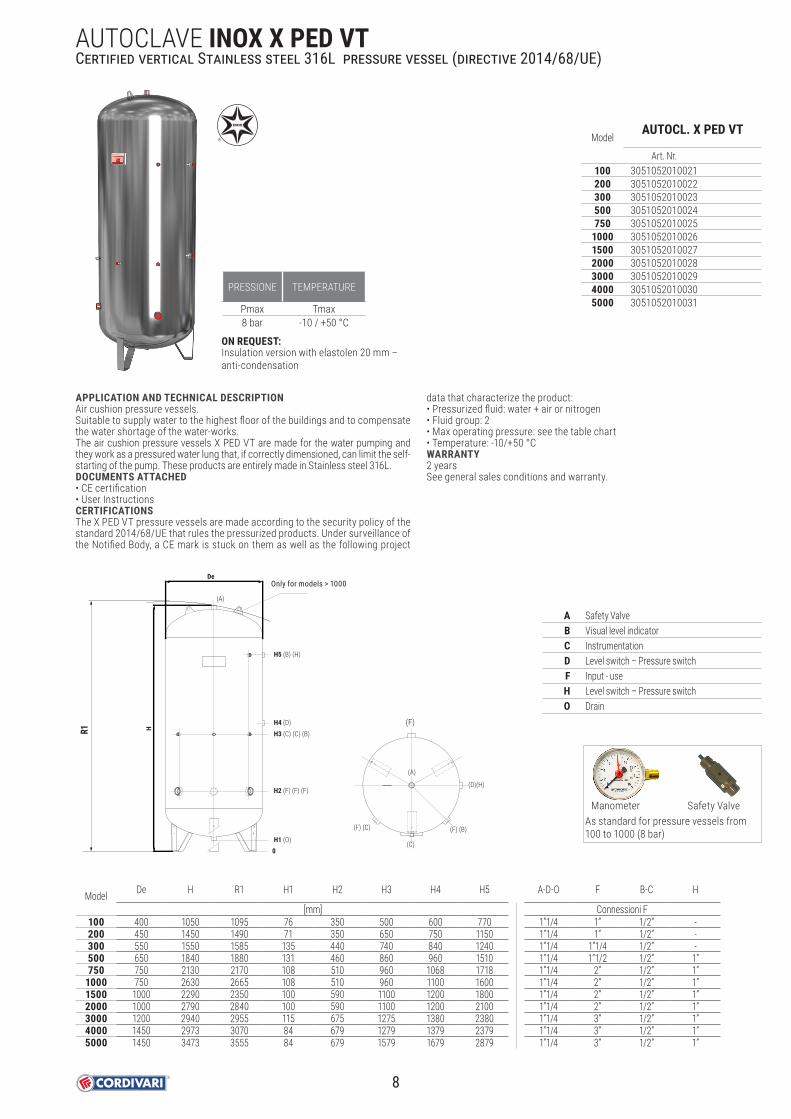
APPLICATION AND TECHNICAL DESCRIPTIONAir cushion pressure vessels.Suitable to supply water to the highest floor of the buildings and to compensate the water shortage of the water-works.The air cushion pressure vessels X PED VT are made for the water pumping and they work as a pressured water lung that, if correctly dimensioned, can limit the self-starting of the pump. These products are entirely made in Stainless steel 316L.DOCUMENTS ATTACHED• CE certification• User InstructionsCERTIFICATIONSThe X PED VT pressure vessels are made according to the security policy of the standard 2014/68/UE that rules the pressurized products. Under surveillance of the Notified Body, a CE mark is stuck on them as well as the following project
data that characterize the product:• Pressurized fluid: water + air or nitrogen• Fluid group: 2• Max operating pressure: see the table chart• Temperature: -10/+50 °CWARRANTY 2 yearsSee general sales conditions and warranty.
R1
H1 (O)
H2 (F) (F) (F)
H4 (D)
H5 (B) (H)
H3 (C) (C) (B)
(A)
0
(F)
(C)
(A)
(D)(H)
(F) (C) (F) (B)
De
H
solo su capacita >1000 lt
A Safety ValveB Visual level indicatorC InstrumentationD Level switch – Pressure switchF Input - useH Level switch – Pressure switchO Drain
Model De H R1 H1 H2 H3 H4 H5 A-D-O F B-C H
[mm] Connessioni F100 400 1050 1095 76 350 500 600 770 1”1/4 1” 1/2” -200 450 1450 1490 71 350 650 750 1150 1”1/4 1” 1/2” -300 550 1550 1585 135 440 740 840 1240 1”1/4 1”1/4 1/2” -500 650 1840 1880 131 460 860 960 1510 1”1/4 1”1/2 1/2” 1”750 750 2130 2170 108 510 960 1068 1718 1”1/4 2” 1/2” 1”
1000 750 2630 2665 108 510 960 1100 1600 1”1/4 2” 1/2” 1”1500 1000 2290 2350 100 590 1100 1200 1800 1”1/4 2” 1/2” 1”2000 1000 2790 2840 100 590 1100 1200 2100 1”1/4 2” 1/2” 1”3000 1200 2940 2955 115 675 1275 1380 2380 1”1/4 3” 1/2” 1”4000 1450 2973 3070 84 679 1279 1379 2379 1”1/4 3” 1/2” 1”5000 1450 3473 3555 84 679 1579 1679 2879 1”1/4 3” 1/2” 1”
PRESSIONE TEMPERATURE
Pmax Tmax8 bar -10 / +50 °C
AUTOCLAVE INOX X PED VTCertified vertical Stainless steel 316L pressure vessel (directive 2014/68/UE)
As standard for pressure vessels from 100 to 1000 (8 bar)
Manometer Safety Valve
ON REQUEST:Insulation version with elastolen 20 mm – anti-condensation
Only for models > 1000
8
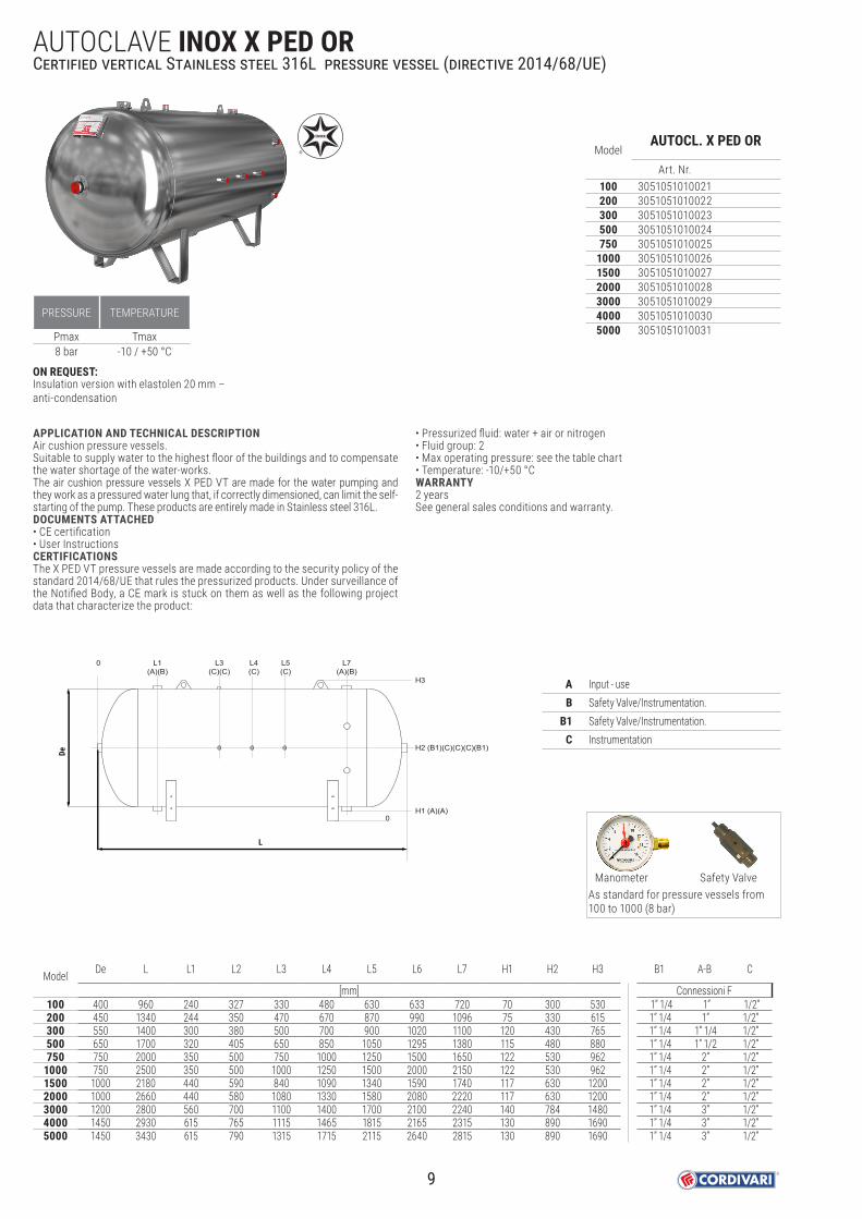
APPLICATION AND TECHNICAL DESCRIPTIONAir cushion pressure vessels.Suitable to supply water to the highest floor of the buildings and to compensate the water shortage of the water-works.The air cushion pressure vessels X PED VT are made for the water pumping and they work as a pressured water lung that, if correctly dimensioned, can limit the self-starting of the pump. These products are entirely made in Stainless steel 316L.DOCUMENTS ATTACHED• CE certification• User InstructionsCERTIFICATIONSThe X PED VT pressure vessels are made according to the security policy of the standard 2014/68/UE that rules the pressurized products. Under surveillance of the Notified Body, a CE mark is stuck on them as well as the following project data that characterize the product:
• Pressurized fluid: water + air or nitrogen• Fluid group: 2• Max operating pressure: see the table chart• Temperature: -10/+50 °CWARRANTY 2 yearsSee general sales conditions and warranty.
ModelAUTOCL. X PED OR
Art. Nr.100 3051051010021200 3051051010022300 3051051010023500 3051051010024750 3051051010025
1000 30510510100261500 30510510100272000 30510510100283000 30510510100294000 30510510100305000 3051051010031
Model De L L1 L2 L3 L4 L5 L6 L7 H1 H2 H3 B1 A-B C
[mm] Connessioni F100 400 960 240 327 330 480 630 633 720 70 300 530 1” 1/4 1” 1/2” 200 450 1340 244 350 470 670 870 990 1096 75 330 615 1” 1/4 1” 1/2” 300 550 1400 300 380 500 700 900 1020 1100 120 430 765 1” 1/4 1” 1/4 1/2” 500 650 1700 320 405 650 850 1050 1295 1380 115 480 880 1” 1/4 1” 1/2 1/2” 750 750 2000 350 500 750 1000 1250 1500 1650 122 530 962 1” 1/4 2” 1/2”
1000 750 2500 350 500 1000 1250 1500 2000 2150 122 530 962 1” 1/4 2” 1/2” 1500 1000 2180 440 590 840 1090 1340 1590 1740 117 630 1200 1” 1/4 2” 1/2” 2000 1000 2660 440 580 1080 1330 1580 2080 2220 117 630 1200 1” 1/4 2” 1/2” 3000 1200 2800 560 700 1100 1400 1700 2100 2240 140 784 1480 1” 1/4 3” 1/2” 4000 1450 2930 615 765 1115 1465 1815 2165 2315 130 890 1690 1” 1/4 3” 1/2” 5000 1450 3430 615 790 1315 1715 2115 2640 2815 130 890 1690 1” 1/4 3” 1/2”
PRESSURE TEMPERATURE
Pmax Tmax8 bar -10 / +50 °C
AUTOCLAVE INOX X PED ORCertified vertical Stainless steel 316L pressure vessel (directive 2014/68/UE)
A Input - useB Safety Valve/Instrumentation.
B1 Safety Valve/Instrumentation. C Instrumentation
De
L
L3(C)(C)
0 L4(C)
L5(C)
L1(A)(B)
H2 (B1)(C)(C)(C)(B1)
H1 (A)(A)
H3
L7(A)(B)
0
As standard for pressure vessels from 100 to 1000 (8 bar)
Manometer Safety Valve
ON REQUEST:Insulation version with elastolen 20 mm – anti-condensation
9

SIMPLE PRESSURE VESSEL DIRECTIVE (SPVD)The SPVD Directive applies to pressure vessels for air or nitrogen made of steel or aluminium alloy, with a maximum working pressure higher than 0.5 bar and less than 30 bar and with the product of the maximum working pressure and the capacity of the vessel (PS x V) between 50 bar*l and 10,000 bar*l and with an operating temperaturebetween -50 °C and +300 °C for steel and max. 100 °C for aluminium.
COMPRESSED AIR RECEIVERS P.E.D.TESTED PRESSURIZED TANKS FOR COMPRESSED AIR CE marked storage tanks for pressurized air in compliance with Directive 2014/68/UE P.E.D.The range of tested pressurized tanks PED includes all the pressurized storages designed for accumulation of compressed air.These products are manufactured according the European Directive for pressurized devices (2014/68/UE Pressure Equipment Device) and are designed to contain fluids at high pressure and/or temperature.
10

THE PRESSURE EQUIPMENT DEVICE (P.E.D.) DIRECTIVEAny device that overcomes the maximum working pressure limit of 0,5 BAR is subject to design and manufacture indications according to the directive 2014/68/EU.
This directive establishes an index of hazardousness of the equipment (tanks in our case), determined according to the type of fluid contained, the maximum temperature admissible, the pressure and the capacity of the tank.
Fluids are categorized in 2 groups:• GROUP 1, hazardous fluids (explosive, flammable, easily flammable, highly flammable, oxidizer, toxic and highly toxic)• GROUP 2, not hazardous fluids (all fluids that are not included in GROUP 1)
Note: all the Cordivari products involved in the application of the PED directive are intended to contain fluids belonging to GROUP 2 (water, steam, compressed air).The categorization of the equipment in accordance with the level of hazardousness is established in the Annex II of the directive that defines six classes:
USE OF PRESSURE EQUIPMENT ACCORDING TO ITALIAN LAWS AND REGULATIONSThe use of pressure equipment is regulated in Italy by Ministerial Decree No. 329/2004. This decree establishes requirements for the correct operation of pressure equipments both during installation and start-up and in terms of subsequent periodic checks. On this regard, following activities are defined: • DECLARATION OF COMMISSIONING: Is intended the declaration to be submitted to National Labour Security Institute and to the competent for the territory
Sanitary Office, containing the following annexes according to the provisions of art. 6.1 of Ministerial Decree no. 329/2004.• FIRST INSTALLATION COMMISSIONING: control consisting in verifying by competent approved body (Labour or Medical Institute) that the tank has been correctly
installed in compliance with user manual and maintenance issued by the manufacturer of the equipment and in compliance with the local laws in force.• PERIODICAL RE-QUALIFICATION: compulsory periodic checks to be carried out by authorised bodies on pressure equipments in service under responisibility of
user, in order to check the compliance for a continuous operation.• OPERATION CHECK: performed to assess the compliance of the actual conditions of use of the equipment with what is reported in the declaration of
commissioning and in manual. During this phase, the safety accessories are also subjected to a functional check.• INTEGRITY CHECK: this is carried out through a visual examination both inside and outside the pressure equipment and through instrumental checks that
determine whether the equipment is still within the limits set by the manufacturer, e.g. by checking the thickness.
DECREE 329 states exclusions cases (total or partial) from the operational checks, according to following scheme.
Category Application of the PED directive CE Marking Reference
PS ≤ 0,5 and specific exceptions Not applicable No Art. 1.1 e 1.2
PS ≥ 0,5 in conditions of low hazard level Applicable No Art. 4.3
Category I Applicable Yes
Table from 1 to 9 Annex II
Category II Applicable Yes
Category III Applicable Yes
Category IV Applicable Yes
COMPRESSED AIR RECEIVERS P.E.D.
CAPACITYV [litri]
MAXIMUM OPERATING PRESSURE
PS [bar]
PS x V[bar x litro]
POTENTIAL CORROSION
INTERNAL OR EXTERNAL (*)
DECLARATION OF COMMISSIONING
COMMISSIONINGCHECK
PERIODICREQUALIFICATION
≤ 25 whatever − − No NoNo (**)25 < V ≤ 50 ≤ 12 − − No No
> 50≤ 12 ≤ 8000 No Yes No≤ 12 ≤ 8000 Yes Yes No Yes (***)≤ 12 ≤ 12000 No Yes Yes No (**)
(*) The absence of corrosive phenomena inside or outside the equipments can be declared by the designer in the declaration of commissioning only for fluid under Group 2 , except steam.
(**) The user must always follow the instructions in the operating and maintenance manual.
(***) Always to be carried out by an approved body.Categories I and II Functional check Four-yearly - Integrity check Ten-yearly Categories III and IV Operation check Every four years - Integrity check: Every ten years
We recommend always to check the national laws in force at place of installation for the use of pressure equipment.
11

COMPRESSORE
WORKING TEMPERATURETmax
-10/+100 °C
TECHNICAL DESCRIPTIONCompressed air receivers allows to extract more air than the quantity produced by compressor, this without causing an under-pressure in the unit.Built in mild steel, either painted, galvanized and painted with internal Polywarm® coating according to D.M. nr. 174 dated 06/04/2004. APPLICATIONStorage and distribution of compressed air.MATERIALE• Painted mild steel (standard colour RAL 5002-Blue). Other colours on demand:
RAL 5015 - Light Blue / RAL 3000 - Red / RAL 1021 - Yellow• Galvanized mild steel.• Painted mild steel version with internal Polywarm® coating.DOCUMENTS ATTACHED• CE certification - User Instructions
CERTIFICATIONSCompressed air receivers are produced according to European Directive 2014/29/CE for items with a “volume x pressure” minor than 10.000 Bar x Liter. These tanks are marked CE under the monitoring of an external control agency. • Liquid in pressure: air • Liquid group: 2 • Maximum working pressure: (See tab) • Temperature: -10/+100°C
2014/29/CE VERTICAL COMPRESSED AIR RECEIVER
ModelPressure Galvanized PAINTED - RAL 5002 BLUE (*)
[Bar] Art. Nr. Art. Nr.100
113053171990001 3053172240001
200 3053171990022 3053172240022270 3053171990003 3053172240003500 3053171990004 3053172240004710 3053171990025 3053172240025900 3053171990026 3053172240026270 15 3053171990034 3053172240034500 3053171990014 3053172240014
2014/29/CE VERTICAL COMPRESSED AIR RECEIVER
ModelPressure PAINTED RAL 5002 BLUE (*)
FOOD INTERNAL COATING[Bar]
100
11200270500710900270 15500
FOOD
INTE
RNAL
COA
TING
GALV
ANIZ
ED /
PAIN
TED
(*) Other colours on demand:RAL 5015 Light Blue / RAL 3000 Red / RAL 1021 Yellow
(*) Other colours on demand:RAL 5015 Light Blue / RAL 3000 Red / RAL 1021 Yellow
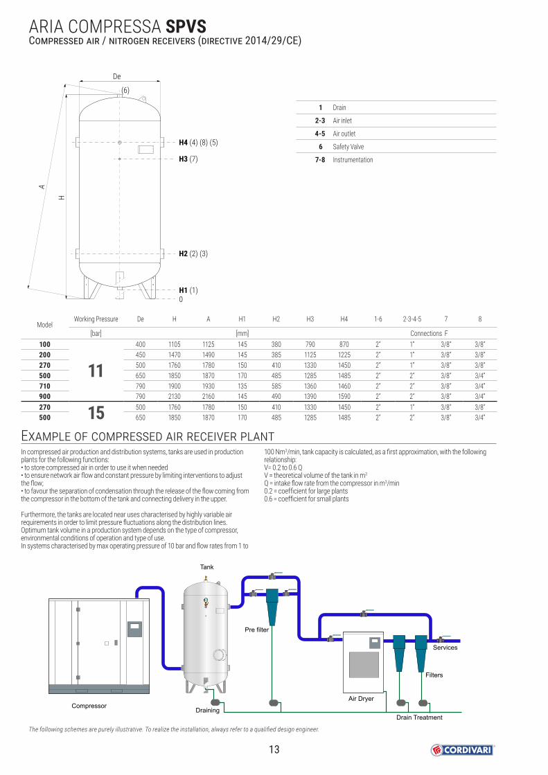
ARIA COMPRESSA SPVS Compressed air / nitrogen receivers (directive 2014/29/CE)
STOCK AVAILABILITY
AIR COMPRESSOR
12
De
H
A
H2 (2) (3)
H1 (1)
H4 (4) (8) (5)
H3 (7)
(6)
0
1 Drain
2-3 Air inlet
4-5 Air outlet
6 Safety Valve
7-8 Instrumentation
In compressed air production and distribution systems, tanks are used in production plants for the following functions:• to store compressed air in order to use it when needed • to ensure network air flow and constant pressure by limiting interventions to adjust the flow; • to favour the separation of condensation through the release of the flow coming from the compressor in the bottom of the tank and connecting delivery in the upper.
Furthermore, the tanks are located near uses characterised by highly variable air requirements in order to limit pressure fluctuations along the distribution lines.Optimum tank volume in a production system depends on the type of compressor, environmental conditions of operation and type of use.In systems characterised by max operating pressure of 10 bar and flow rates from 1 to
100 Nm3/min, tank capacity is calculated, as a first approximation, with the following relationship:V= 0.2 to 0.6 QV = theoretical volume of the tank in m3
Q = intake flow rate from the compressor in m3/min0.2 = coefficient for large plants0.6 = coefficient for small plants
Compressor
Tank
Air Dryer
Pre filter
Filters
Services
Drain TreatmentDraining
Example of compressed air receiver plant
ModelWorking Pressure De H A H1 H2 H3 H4 1-6 2-3-4-5 7 8
[bar] [mm] Connections F100
11400 1105 1125 145 380 790 870 2” 1” 3/8” 3/8”
200 450 1470 1490 145 385 1125 1225 2” 1” 3/8” 3/8”270 500 1760 1780 150 410 1330 1450 2” 1” 3/8” 3/8”500 650 1850 1870 170 485 1285 1485 2” 2” 3/8” 3/4”710 790 1900 1930 135 585 1360 1460 2” 2” 3/8” 3/4”900 790 2130 2160 145 490 1390 1590 2” 2” 3/8” 3/4”270 15 500 1760 1780 150 410 1330 1450 2” 1” 3/8” 3/8”500 650 1850 1870 170 485 1285 1485 2” 2” 3/8” 3/4”
The following schemes are purely illustrative. To realize the installation, always refer to a qualified design engineer.
ARIA COMPRESSA SPVS Compressed air / nitrogen receivers (directive 2014/29/CE)
13

TECHNICAL DESCRIPTIONCompressed air receivers allows to extract more air than the quantity produced by compressor, this without causing an under-pressure in the unit.Built in mild steel, either painted, galvanized and painted with internal Polywarm® coating according to D.M. nr. 174 dated 06/04/2004. APPLICATIONStorage and distribution of compressed air.MATERIALE• Painted mild steel (standard colour RAL 5002-Blue). Other colours on demand:
RAL 5015 - Light Blue / RAL 3000 - Red / RAL 1021 - Yellow• Galvanized mild steel.• Painted mild steel version with internal Polywarm® coating.DOCUMENTS ATTACHED• CE certification - User Instructions
CERTIFICATIONSCompressed air receivers are produced according to European Directive 2014/29/CE for items with a “volume x pressure” minor than 10.000 Bar x Liter. These tanks are marked CE under the monitoring of an external control agency. • Liquid in pressure: air • Liquid group: 2 • Maximum working pressure: (See tab) • Temperature: -10/+100°C
FOOD
INTE
RNAL
COA
TING
2014/68/CE-P.E.D. VERTICAL COMPRESSED AIR RECEIVER
ModelPressure Galvanized PAINTED - RAL 5002 BLUE (*)
[Bar] Art. Nr. Art. Nr.1500
8
3054171990001 30541722400012000 3054171990002 30541722400023000 3054171990054 30541722400544000 3054171990005 30541722400055000 3054171990006 30541722400068000 3054171990032 /
10000 3054171990033 /1000
12
3054171990067 30541722400671500 3054171990011 30541722400112000 3054171990012 30541722400122500 3054171990013 30541722400133000 3054171990064 30541722400644000 3054171990015 30541722400155000 3054171990016 30541722400168000 3054171990030 /
10000 3054171990031 /1000
153054171990167 3054172240151
1500 3054171990118 30541722401022000 3054171990168 3054172240152
2014/68/CE-P.E.D. VERTICAL COMPRESSED AIR RECEIVER WITH MANHOLD
ModelPressure Galvanized
[Bar] Art. Nr.8000 8 3054171990007
10000 30541719900088000 12 3054171990027
10000 3054171990028
(*) Other colours on demand:RAL 5015 Light Blue / RAL 3000 Red / RAL 1021 Yellow
GALV
ANIZ
ED /
PAIN
TED
(*) Other colours on demand:RAL 5015 Light Blue / RAL 3000 Red / RAL 1021 Yellow
VERTICAL COMPRESSED AIR RECEIVER - POLYWARM® (2014/68/CE-P.E.D.)
Pressure PAINTED RAL 5002 BLUE (*) - FOOD INTERNAL COATING[Bar]
81215
WORKING TEMPERATURETmax
-10/+100 °C
COMPRESSORE
ARIA COMPRESSA P.E.D. VT Compressed air / nitrogen receivers (directive 2014/68/UE - P.E.D.)
STOCK AVAILABILITY
AIR COMPRESSOR
14

1 Drain
2-3 Air inlet
4-5 Air outlet
6 Safety Valve
7-8 Instrumentation
9 Manhole / handhole (on request)
ModelWorking Pressure De H A H1 H2 H3 H4 H5 1-6 2-3-4-5 7 8
[bar] [mm] Connections F1500
8
950 2470 2510 115 520 1480 1680 860 2" 2” 3/8" 3/4"2000 1100 2545 2600 100 595 1495 1695 890 2" 2” 3/8" 3/4"3000 1200 2950 3075 140 680 1580 1780 985 2" 3" 3/8" 3/4"4000 1450 3010 3100 115 710 1610 1810 1010 2" 3" 3/8" 3/4"5000 1450 3510 3585 115 710 2100 2300 1010 2" 3" 3/8" 3/4"8000 1650 4200 4280 200 905 3310 3510 1150 2" 4" 3/8" 3/4"
10000 1650 5200 5270 200 905 4310 4510 1150 2" 4" 3/8" 3/4"1000
12
790 2440 2470 180 575 1625 1825 870 2" 2” 3/8" 3/4"1500 950 2470 2510 115 520 1480 1680 860 2" 2” 3/8" 3/4"2000 1100 2545 2600 100 595 1495 1695 890 2" 2” 3/8" 3/4"2500 1200 2660 2760 140 680 1580 1780 985 2" 3” 3/8" 3/4"3000 1200 2950 3075 140 680 1580 1780 985 2" 3" 3/8" 3/4"4000 1450 3010 3100 115 710 1610 1810 1010 2" 3" 3/8" 3/4"5000 1450 3510 3585 115 710 2100 2300 1010 2" 3" 3/8" 3/4"8000 1650 4200 4280 200 905 3310 3510 1150 2" 4" 3/8" 3/4"
10000 1650 5200 5270 200 905 4310 4510 1150 2" 4" 3/8" 3/4"1000
15790 2440 2470 180 575 1625 1825 870 2" 2” 3/8" 3/4"
1500 950 2470 2510 115 520 1480 1680 860 2" 2” 3/8" 3/4"2000 1100 2545 2600 100 595 1495 1695 890 2" 2” 3/8" 3/4"
DeH
A
H2 (2) (3)
H1 (1)
H4 (4) (8) (5)
H3 (7)
(6)
0
H5 (9)
H5 and 9 are referred to manhole and handhole versions, see Accessories section.
ARIA COMPRESSA P.E.D. VTCompressed air / nitrogen receivers (directive 2014/68/UE - P.E.D.)
15

ARIA COMPRESSA P.E.D. VT 11-15 BARCompressed air / nitrogen receivers (directive 2014/68/UE - P.E.D.)
2014/68/CE-P.E.D. VERTICAL COMPRESSED AIR RECEIVER
ModelPressure Galvanized PAINTED - RAL 5002 BLUE (*)
[Bar] Art. Nr. Art. Nr.100
11 3053171990101 3053172240110
200 3053171990102 3053172240111 270 3053171990103 3053172240112 500 3053171990104 3053172240113 710 3053171990105 3053172240114 900 3053171990106 3053172240115 200
153053171990107 3053172240116
270 3053171990108 3053172240117500 3053171990109 3053172240118
WORKING TEMPERATURETmax
-10/+100 °C
COMPRESSORE
FOOD
INTE
RNAL
COA
TING
(*) Other colours on demand:RAL 5015 Light Blue / RAL 3000 Red / RAL 1021 Yellow
GALV
ANIZ
ED /
PAIN
TED
(*) Other colours on demand:RAL 5015 Light Blue / RAL 3000 Red / RAL 1021 Yellow
VERTICAL COMPRESSED AIR RECEIVER - POLYWARM® (2014/68/CE-P.E.D.)
ModelPressure PAINTED RAL 5002 BLUE (*)
FOOD INTERNAL COATING[Bar]
100
11200270500710900270
15200500
TECHNICAL DESCRIPTIONCompressed air receivers allows to extract more air than the quantity produced by compressor, this without causing an under-pressure in the unit.Built in mild steel, either painted, galvanized and painted with internal Polywarm® coating according to D.M. nr. 174 dated 06/04/2004. APPLICATIONStorage and distribution of compressed air.MATERIALE• Painted mild steel (standard colour RAL 5002-Blue). Other colours on demand:
RAL 5015 - Light Blue / RAL 3000 - Red / RAL 1021 - Yellow• Galvanized mild steel.• Painted mild steel version with internal Polywarm® coating.DOCUMENTS ATTACHED• CE certification - User Instructions
CERTIFICATIONSCompressed air receivers are produced according to European Directive 2014/29/CE for items with a “volume x pressure” minor than 10.000 Bar x Liter. These tanks are marked CE under the monitoring of an external control agency. • Liquid in pressure: air • Liquid group: 2 • Maximum working pressure: (See tab) • Temperature: -10/+100°C
STOCK AVAILABILITY
AIR COMPRESSOR
16

ARIA COMPRESSA P.E.D. VT 11-15 BARCompressed air / nitrogen receivers (directive 2014/68/UE - P.E.D.)
1 Drain
2-3 Air inlet
4-5 Air outlet
6 Safety Valve
7-8 Instrumentation
9 Manhole / handhole (on request)
ModelWorking Pressure De H A H1 H2 H3 H4 1-6 2-3-4-5 7 8
[bar] [mm] Connections F100
11400 1105 1125 145 380 790 870 2” 1” 3/8” 3/8”
200 450 1470 1490 145 385 1125 1225 2” 1” 3/8” 3/8”270 500 1760 1780 150 410 1330 1450 2” 1” 3/8” 3/8”500 650 1850 1870 170 485 1285 1485 2” 2” 3/8” 3/4”710 790 1900 1930 135 585 1360 1460 2” 2” 3/8” 3/4”900 790 2130 2160 145 490 1390 1590 2” 2” 3/8” 3/4”200
15450 1470 1490 145 385 1125 1225 2” 1” 3/8” 3/8”
270 500 1760 1780 150 410 1330 1450 2” 1” 3/8” 3/8”500 650 1850 1870 170 485 1285 1485 2” 2” 3/8” 3/4”
De
H
A
H2 (2) (3)
H1 (1)
H4 (4) (8) (5)
H3 (7)
(6)
0
H5 (9)
17

FOOD
INTE
RNAL
COA
TING
2014/68/CE-P.E.D. HORIZONTAL COMPRESSED AIR RECEIVER
ModelPressure Galvanized PAINTED - RAL 5002 BLUE (*)
[Bar] Art. Nr. Art. Nr.1500
8
3054170990001 3054171340001 2000 3054170990002 3054171340002 3000 3054170990004 3054171340054 4000 3054170990005 3054171340005 5000 3054170990006 3054171340006 8000 3054170990007 /
10000 3054170990008 /100
113053170990101 3053171340110
200 3053170990102 3053171340111270 3053170990103 3053171340112500 3053170990104 3053171340113710 3053170990105 3053171340114900 3053170990106 3053171340115
1000
12
3054170990611 3054171340067 1500 3054170990011 3054171340011 2000 3054170990012 3054171340012 2500 3054170990013 3054171340013 3000 3054170990020 3054171340064 4000 3054170990015 3054171340015 5000 3054170990016 3054171340016 8000 3054170990017 /
10000 3054170990018 /200
153053170990107 3053171340116
270 3053170990108 3053171340117500 3053170990109 3053171340118
(*) Other colours on demand:RAL 5015 Light Blue / RAL 3000 Red / RAL 1021 Yellow
GALV
ANIZ
ED /
PAIN
TED
(*) Other colours on demand:RAL 5015 Light Blue / RAL 3000 Red / RAL 1021 Yellow
HORIZONTAL COMPRESSED AIR RECEIVER - POLYWARM® (2014/68/CE-P.E.D.)
Pressure PAINTED RAL 5002 BLUE (*) - FOOD INTERNAL COATING[Bar]
8111215
WORKING TEMPERATURETmax
-10/+100 °C
COMPRESSORE
ARIA COMPRESSA P.E.D. OR
TECHNICAL DESCRIPTIONCompressed air receivers allows to extract more air than the quantity produced by compressor, this without causing an under-pressure in the unit.Built in mild steel, either painted, galvanized and painted with internal Polywarm® coating according to D.M. nr. 174 dated 06/04/2004. APPLICATIONStorage and distribution of compressed air.MATERIALE• Painted mild steel (standard colour RAL 5002-Blue). Other colours on demand:
RAL 5015 - Light Blue / RAL 3000 - Red / RAL 1021 - Yellow• Galvanized mild steel.• Painted mild steel version with internal Polywarm® coating.DOCUMENTS ATTACHED• CE certification - User Instructions
CERTIFICATIONSCompressed air receivers are produced according to European Directive 2014/29/CE for items with a “volume x pressure” minor than 10.000 Bar x Liter. These tanks are marked CE under the monitoring of an external control agency. • Liquid in pressure: air • Liquid group: 2 • Maximum working pressure: (See tab) • Temperature: -10/+100°C
AIR COMPRESSOR
Compressed air / nitrogen receivers (directive 2014/68/UE - P.E.D.)
18

ModelWorking Pressure De L L1 L2 L3 L5 L6 L7 H1 H2 H3 A B C
[bar] [mm] Connections F1500
8
950 2360 420 565 1080 1280 1795 1940 117 640 1196 2” 2” 3/8” 3/4"2000 1100 2450 470 615 1125 1325 1835 1980 100 700 1330 2” 2” 3/8” 3/4"3000 1200 2770 550 700 1285 1485 2070 2220 140 784 1480 2” 3” 3/8” 3/4"4000 1450 2890 600 750 1345 1545 2140 2290 122 887 1670 2” 3” 3/8” 3/4"5000 1450 3390 600 750 1595 1795 2640 2790 122 887 1670 2” 3” 3/8” 3/4"8000 1650 3990 700 860 2495 2745 3130 3290 240 1100 2100 2” 4” 3/8” 3/4"10000 1650 4990 700 860 3150 3400 4130 4290 240 1100 2100 2” 4” 3/8” 3/4"
100
11400 950 225 310 340 - 640 725 80 305 566 2” 1/2” 3/8” 3/4"
200 450 1340 235 350 390 - 990 1105 80 330 615 2” 1/2” 3/8” 3/4"270 500 1620 250 365 405 - 1255 1370 130 407 717 2” 1/2” 3/8” 3/4"500 650 1700 295 400 440 - 1300 1405 130 480 870 2” 1/2” 3/8” 1"710 790 1700 380 450 500 - 1250 1320 110 532 987 2” 1” 3/8” 1/2"900 790 2000 380 450 550 - 1550 1620 110 532 987 2” 1” 3/8” 1/2"1000
12
790 2250 350 570 1025 1225 1680 1900 110 532 987 2” 2” 3/8” 3/4"1500 950 2360 420 565 2260 2460 1795 1940 117 640 1196 2” 2” 3/8” 3/4"2000 1100 2450 470 615 2350 2550 1835 1980 100 700 1330 2” 2” 3/8” 3/4"2500 1200 2520 510 655 2420 2620 1865 2010 140 800 1480 2” 3” 3/8” 3/4"3000 1200 2770 550 700 2670 2870 2070 2220 140 784 1480 2” 3” 3/8” 3/4"4000 1450 2890 600 750 2790 2990 2140 2290 122 887 1670 2” 3” 3/8” 3/4"5000 1450 3390 600 750 3290 3490 2640 2790 122 887 1670 2” 3” 3/8” 3/4"8000 1650 3990 700 860 2495 2745 3130 3290 240 1100 2100 2” 4” 3/8” 3/4"10000 1650 4990 700 860 3150 3400 4130 4290 240 1100 2100 2” 4” 3/8” 3/4"
200
15450 1340 235 350 390 - 990 1105 80 330 615 2” 1/2” 3/8” 3/4"
270 500 1620 250 365 405 - 1255 1370 130 407 717 2” 1/2” 3/8” 3/4"500 650 1700 295 400 440 - 1300 1405 130 480 870 2” 1/2” 3/8” 1"
ARIA COMPRESSA P.E.D. OR
A Input - use B Safety Valve/Instrumentation
B1 Safety Valve/Instrumentation C Instrumentation
De
L
L3(C)(C)
0 L5(C)
L1(A)(B)
H2 (A)(C)(C)(B)
H1 (A)(A)
H3
L7(A)(B)
0
Compressed air / nitrogen receivers (directive 2014/68/UE - P.E.D.)
19

Pressure vessels visual level indicator
Art. Nr. Pressure vessel model Tube length [m]
5303000000040 From 100 to 2500 (stainless steel 1000 and 2000 excluded) 1
5303000000041 From 3000 to 5000 (stainless steel 1000 and 2000 included) 2
5303000000042 >5000 on request 3
The level indicator includes: transparent tube, two brass faucets and gaskets.
Pressure gauge
Art. Nr. Units box Connection [Bar]
5300000001001 5 pcs 1/4” 0/10
5300000001002 5 pcs 1/4” 0/16
Instruments installed on pressure equipment to indicate at any time the pressure which the vessel is subjected. All pressure gauges are supplied with an adjustable indicator for maximum pressure.
Bottom connection
Air compressor receivers KITArt. Nr. Description
5303000000001 Kit for 200 up to 710 lt compressed air receivers (11 bar), with security valve of 7.000 l./min P calibration 10,4 bar
5303000000002 Kit for 900 lt compressed air receivers (11 bar), with security valve of 30.000 l./min P calibration 10,4 bar
5303000000003 Kit for 1.000 up to 10.000 lt compressed air receivers (12 bar), with security valve of 32.000 l./min P calibration 11,2 bar
5303000000004 Kit for 1.000 up to 10.000 lt compressed air receivers (8 bar), with security valve of 22.000 l./min P calibration 7,4 bar
5303000000005 Kit for 270 up to 2.000 lt compressed air receivers (15 bar), with security valve of 9.000 l./min P calibration 13,5 bar
Includes a safety valve , a gauge (manometer) and its tap-tray.
Right-sideconnection
Approved safety valves for discharging compressed air or inert gases Applied to compressed air and liquid lift tanks prevent the maximum working pressure from being exceeding the limits of designed conditions. The choice of the safety valve should be assessed, in addition to the maximum pressure, in relation to the discharge flow rate and is therefore closely linked to the origin of the system of which the tank is part of and the causes which may lead to the intervention of such devices For these reasons, the choice of the safety valve to be used is the responsibility of the system designer.All safety valves supplied are accompanied by an EC certificate of conformity issued by a notified body and their installation is regulated by the national regulations on pressure equipment in force.
Art. Nr. Units box Connection Calibration [Bar]
Drain flow [Lt/min]
5302000001001
5 pcs
3/8” 4,6 3350
5302000001002 3/8” 5,6 3960
5302000001003 3/8” 7,45 5080
5302000001004 3/8” 9,3 6200
5302000001005 3/8” 10,4 6860
5302000001006 3/8” 11,2 7340
5302000001010
3 pcs
3/4” 4,6 8700
5302000001011 3/4” 5,6 10120
5302000001012 3/4” 7,45 12740
5302000001013 3/4” 10,4 16920
5302000001014 3/4” 11,2 18050
5302000000012
1 pcs
1” 5,6 17220
5302000000007 1” 7,45 22200
5302000000016 1” 10,4 30140
5302000000008 1” 11,2 32290
Safety Valve
ACCESSORIES
20
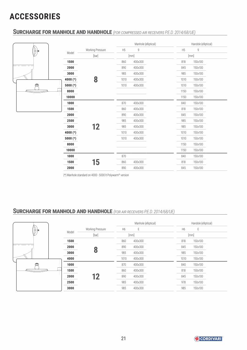
ACCESSORIES
Surcharge for manhole and handhole (for compressed air receivers P.E.D. 2014/68/UE)
ModelWorking Pressure
[bar]
1500
82000
3000
4000 (*)
5000 (*)
8000
10000
1000
12
1500
2000
2500
3000
4000 (*)
5000 (*)
8000
10000
1000
151500
2000
Manhole (elliptical)
H5 9
[mm]
860 400x300
890 400x300
985 400x300
1010 400x300
1010 400x300
870 400x300
860 400x300
890 400x300
985 400x300
985 400x300
1010 400x300
1010 400x300
870
860 400x300
890 400x300
Handole (elliptical)
H5 9
[mm]
818 150x100
845 150x100
985 150x100
1010 150x100
1010 150x100
1150 150x100
1150 150x100
840 150x100
818 150x100
845 150x100
985 150x100
985 150x100
1010 150x100
1010 150x100
1150 150x100
1150 150x100
840 150x100
818 150x100
845 150x100
(*) Manhole standard on 4000 - 5000 lt Polywarm® version
Surcharge for manhold and handhole (for air receivers P.E.D. 2014/68/UE)
ModelWorking Pressure
[bar]
1500
82000
3000
4000
1000
121500
2000
2500
3000
Manhole (elliptical)
H6 E
[mm]
860 400x300
890 400x300
985 400x300
1010 400x300
870 400x300
860 400x300
890 400x300
985 400x300
985 400x300
Handole (elliptical)
H6 E
[mm]
818 150x100
845 150x100
985 150x100
1010 150x100
840 150x100
818 150x100
845 150x100
978 150x100
985 150x100
21

02-2
021
Sales of Cordivari Srl products are made in accordance with the below listed General Conditions of Sale and Guarantee. Any exception to these conditions is subject to written acceptance by Cordivari Srl.
1. SHIPMENTThe goods travel at the risk of the Customer, even if they are delivered at destination. The goods must be checked in the presence of the carrier at the time of delivery, verifying the integrity of the packaging, missing or wrongly shipped items. Any dispute must be immediately reported to the carrier / courier signing the transport document with reserve and confirming this reserve by registered letter within three days from reception of the goods. (Failure to observe this clause will release transport company and Cordivari srl from any liability).
2. DELIVERY TERMSThe delivery terms are approximate and if the proposed delivery time cannot be respected for any reason, the Customer will not be entitled to demand any compensation, penalty payments, cancellation or modification to the order given. In the event of extraordinary events such as natural disasters, strikes, lack of raw materials and force majeure, Cordivari srl reserves the right to choose the measures to be taken. If the ordered goods are not collected within the agreed terms, they will be invoiced and stored with costs, risks and risks for the customer.
3. WEIGHTS, MEASURES, SURFACESWeights, measures, surfaces, shapes, illustrations, images and other data in this catalog or on the products are for illustrative purposes only and are not binding. Cordivari Srl reserves the right to make modifications or variations to its products without prior notice. Always refer to the technical documentation attached to the product and official certificates.
4. ORDER CANCELLATION OR MODIFICATIONWithout the written consent of Cordivari Srl, the orders cannot be canceled or modified neither partially nor totally. No changes or modifications are agreed when the production has already begun. Any costs resulting from the cancellation or modification of the order will be invoiced to the customer.
5. WARRANTY:For all 316 L stainless steel calorifiers, Cordivari Srl guarantees 5 years. For Bolly PRIMO series calorifiers, Cordivari guarantees 2 years.For all calorifiers with internal anti-corrosion treatment in Polywarm®, Cordivari Srl guarantees 5 years.For all tanks with anticorrosive hot galvanizing treatment, Cordivari Srl guarantees 2 years.For all the extractable exchangers and plate exchangers (inspectable and brazed), both mounted on the kettles and sold individually, Cordivari Srl guarantees 2 years.For all PUFFER and MULTIFUEL CYLINDERS buffer tanks, Cordivari Srl guarantees 5 years.For accessories and residual items in this catalog not covered by the general sales conditions, Cordivari Srl guarantees 2 years, with the exception of technical, electrical and electronic components, where the warranty is 12 months.For all non-standard items, special products made to customer specifications, Cordivari Srl guarantees 2 years.The products and systems featured in this catalog are designed and manufactured in compliance with the reference directives CE-EN-UNI-and PED. The guarantee and conformity of these products and systems are only valid in those countries where these standards are recognized and accepted. In non-European countries or in countries that do not comply with these rules, Cordivari assumes no responsibility for warranty or compliance.The warranty covers manufacturing defects. It expires if the points of Article 5 are not respected. The warranty is valid only if the installation of the products has complied with the criteria of protection against overpressure, corrosion, legionella and the installation and use rules and requirements described in this catalog and any other relevant standard regarding system engineering. In the domestic hot water production systems, as well as in the heating ones, comply with the provisions of the UNI CTI 8065 standard which provides for various types of water treatments depending on its characteristics. The warranty does not cover damage resulting from failure to comply with the requirements of the UNI CTI 8065 standard.The commitment to provide the warranty terms is valid only provided that:The product has been stored in good condition and protected from the weather before installation;The product has not been damaged during transport, handling or installation;No tampering or repairs have been carried out by persons not authorized by Cordivari Srl;The installation has been carried out by authorized personnel, in compliance with the instructions and the standards indicated in the technical documentation supplied by Cordivari Srl and with the installation and use rules and instructions given in this catalog and that any provisions of laws or specific technical standards have been observed;The accessories and spare parts used are those regularly supplied by Cordivari Srl;The buyer has made the balance of payments in the pre-established terms;No aggressive chemicals have been added to the water;The operating pressure and temperature indicated in the catalog correspond to the pressure and the limit temperature of use.Any parts subject to natural wear and tear (eg anodes, gaskets, bolts, etc.) are always excluded from any warranty.The warranty starts from the date of the sales invoice of Cordivari Srl and is not renewed in any case in the event of a product replacement.The warranty does not cover costs due to demolitions, work for the passage of products both inbound and outbound and labor for any product replacements.During the warranty period, Cordivari Srl undertakes to replace the product that has been recognized as defective due to proven manufacturing defects, in addition to this, the Customer cannot claim any other compensation for direct or indirect damage costs of any nature to persons and / or things arising from these defects.
6. PAYMENTSThe payments of the invoices must be made within the established deadlines. The delay in the payment of the invoices, even if partial, gives rise to interest on arrears to the extent of the current rate, in addition to the immediate suspension of the shipments in progress.
7. RETENTION OF TITLEUntil the customer has paid the final price of the delivered goods, the products remain property of Cordivari srl. In the event of the buyer’s non-fulfillment, even partial, Cordivari Srl may request the immediate return of the goods, withholding in any case the installments paid as compensation, without prejudice to greater damages.
8. PRICESPrices are not binding and can be changed without notice. Prices can be reviewed based on the variations that may occur up to the time of delivery.Prices are intended for delivery FCA Morro D’Oro (TE), unless otherwise agreed.Prices are always shown in the price list, excluding VAT.For bulky models Cordivari Srl reserves the right to request a participation in the packaging costs.
9. ORDERS/DELIVERYThe minimum order value is 2.000 €. The confirmed orders definitively commit the Customer who must declare to know and accept all the conditions of sale. If the Customer draws up the order by name and on behalf and in the name of others, with the signing of the order he undertakes the fulfillment of what he has agreed. Delivery is intended exclusively at the Customer’s headquarters / warehouse.Special requests of the Customer such as: express deliveries, delivery other than the office / warehouse, etc. will have additional costs that will be communicated from time to time to our sales office.
10. COURT AUTHORITYFor the present Catalogue and conditions only the provisions of Italian law will be used. For controversy, the Court of Teramo (Italy) shall have exclusive competence. Essential and trial law shall be exclusively Italian.
11. ORIGINAL VERSIONTranslation of Cordivari General Sales Conditions and Warranty Terms, reported in this page, derives from the Italian version. In case of possible controversy, the official Cordivari General Sales Conditions and Warranty Terms are the one reported in the Italian language, stated at the back of the Italian catalogues.
©Copyright Cordivari SrlAll rights, in particular those of reproduction, dissemination and translation are reserved.No part of this work may be reprinted or reproduced in any other form without the written permission of Cordivari.This catalog replaces and cancels all previous editions.The company reserves the right to modify the products and data shown in the catalog at any time and is not responsible for any typographical errors.
GENERAL SALES CONDITIONS AND WARRANTY
22


FOLLOW US
www.cordivari.it
CORDIVARI srl
Z. I. Pagliare 64020 Morro D’Oro (TE) • Italy | C.F. / P.Iva e Reg. Imp. TE 00735570673 | Capitale Sociale Euro 4.000.000,00 i.vTel: +39 085 80.40.1 | Fax: +39 085 80.41.418 | [email protected] | www.cordivari.it | UNI EN ISO 9001 | UNI EN ISO 14001