Azionamenti per Motori C.C. e Brushless D.C. and Brushless ... · tata, il motore ruota alla...
18
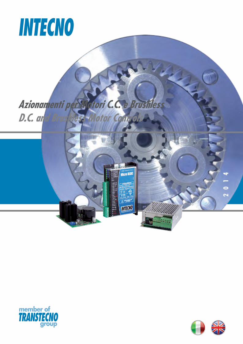
INTECNO TRANSTECNO member of group Azionamenti per Motori C.C. e Brushless D.C. and Brushless Motor Controls 2014
Transcript of Azionamenti per Motori C.C. e Brushless D.C. and Brushless ... · tata, il motore ruota alla...
INTECNO
TRANSTECNOmember of
group
Azionamenti per Motori C.C. e BrushlessD.C. and Brushless Motor Controls
20
14

AZIONAMENTI PER MOTORI C.C. E BRUSHLESSD.C. AND BRUSHLESS MOTOR CONTROLS
H1
Drive
rs
0217A
Questa sezione annulla e sostituisce ogni precedente edizione o revi-sione. Qualora questa sezione non Vi sia giunta in distribuzione con-trollata, l’aggiornamento dei dati ivi contenuto non è assicurato. In tal caso la versione più aggiornata è disponibile sul nostro sito inter-net www.micro-intecno.com
This section replaces any previous edition and revision. If you obtained this catalogue other than through controlled distribution channels, the most up to date content is not guaranteed. In this case the latest ver-sion is available on our web site www.micro-intecno.com
Pag.Page
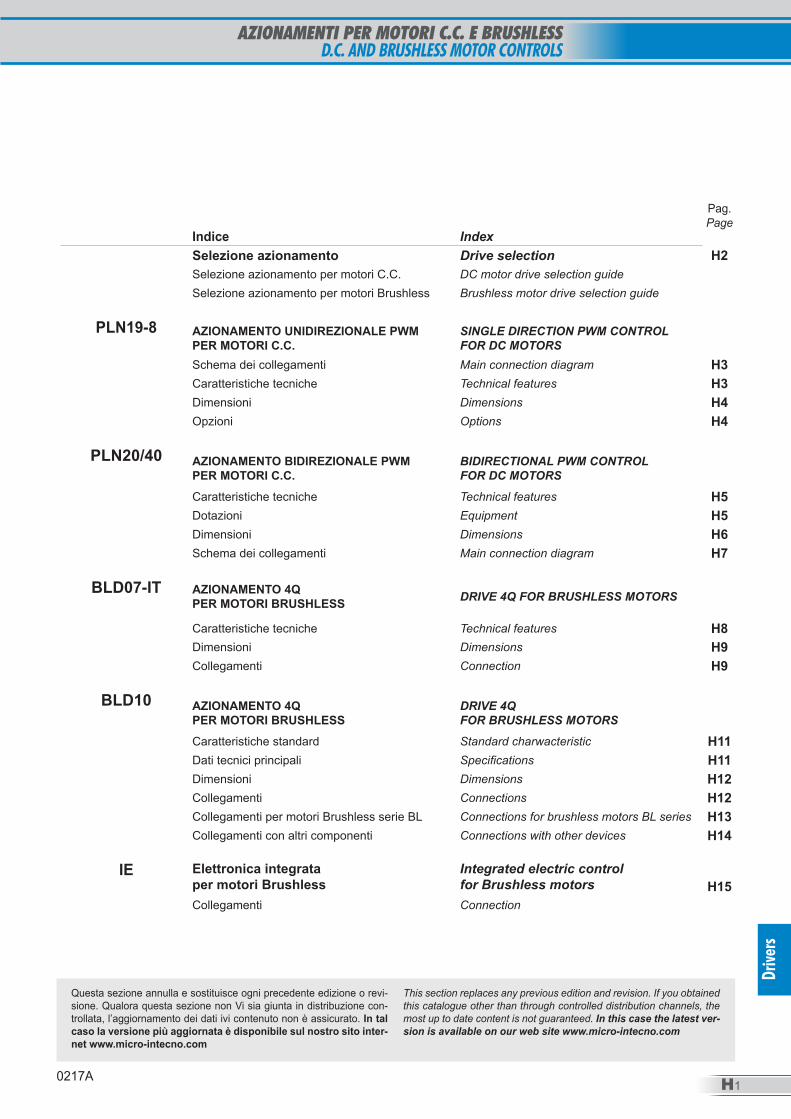
Indice IndexSelezione azionamento Drive selection H2Selezione azionamento per motori C.C. DC motor drive selection guideSelezione azionamento per motori Brushless Brushless motor drive selection guide
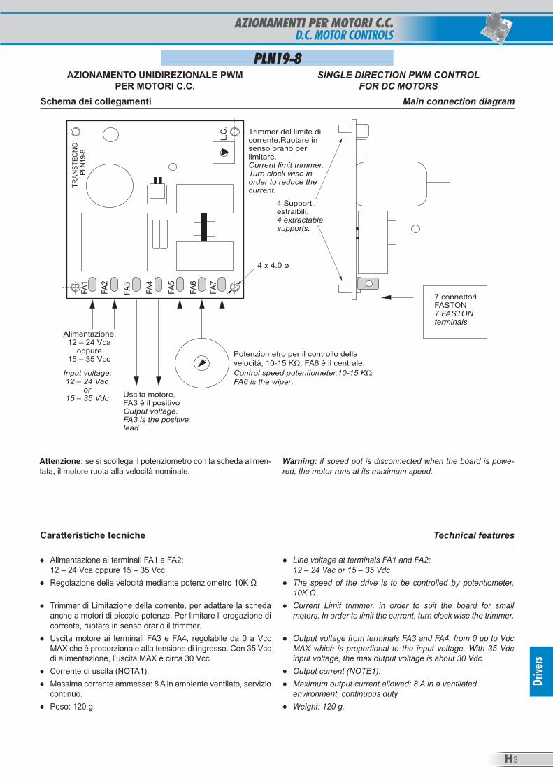
PLN19-8 AZIONAMENTO UNIDIREZIONALE PWM PER MOTORI C.C.
SINGLE DIRECTION PWM CONTROLFOR DC MOTORS
Schema dei collegamenti Main connection diagram H3Caratteristiche tecniche Technical features H3Dimensioni Dimensions H4Opzioni Options H4
PLN20/40 AZIONAMENTO BIDIREZIONALE PWM PER MOTORI C.C.
BIDIRECTIONAL PWM CONTROLFOR DC MOTORS
Caratteristiche tecniche Technical features H5Dotazioni Equipment H5Dimensioni Dimensions H6Schema dei collegamenti Main connection diagram H7
BLD07-IT AZIONAMENTO 4Q PER MOTORI BRUSHLESS DRIVE 4Q FOR BRUSHLESS MOTORS
Caratteristiche tecniche Technical features H8Dimensioni Dimensions H9Collegamenti Connection H9
BLD10 AZIONAMENTO 4QPER MOTORI BRUSHLESS
DRIVE 4QFOR BRUSHLESS MOTORS
Caratteristiche standard Standard charwacteristic H11Dati tecnici principali Specifications H11Dimensioni Dimensions H12Collegamenti Connections H12Collegamenti per motori Brushless serie BL Connections for brushless motors BL series H13Collegamenti con altri componenti Connections with other devices H14
IE Elettronica integrata per motori BrushlessCollegamenti
Integrated electric control for Brushless motorsConnection
H15
AZIONAMENTI PER MOTORI C.C. E BRUSHLESSD.C. AND BRUSHLESS MOTOR CONTROLS
H2
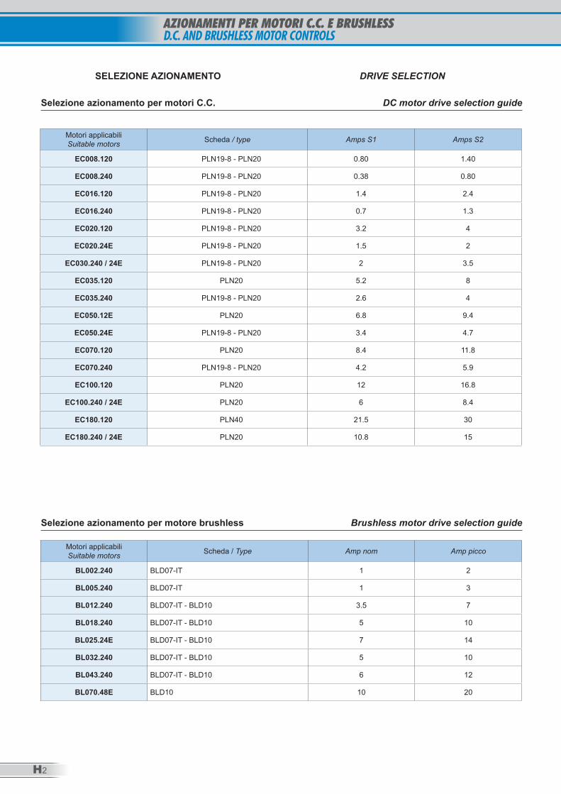
Motori applicabili Suitable motors Scheda / type Amps S1 Amps S2
EC008.120 PLN19-8 - PLN20 0.80 1.40
EC008.240 PLN19-8 - PLN20 0.38 0.80
EC016.120 PLN19-8 - PLN20 1.4 2.4
EC016.240 PLN19-8 - PLN20 0.7 1.3
EC020.120 PLN19-8 - PLN20 3.2 4
EC020.24E PLN19-8 - PLN20 1.5 2
EC030.240 / 24E PLN19-8 - PLN20 2 3.5
EC035.120 PLN20 5.2 8
EC035.240 PLN19-8 - PLN20 2.6 4
EC050.12E PLN20 6.8 9.4
EC050.24E PLN19-8 - PLN20 3.4 4.7
EC070.120 PLN20 8.4 11.8
EC070.240 PLN19-8 - PLN20 4.2 5.9
EC100.120 PLN20 12 16.8
EC100.240 / 24E PLN20 6 8.4
EC180.120 PLN40 21.5 30
EC180.240 / 24E PLN20 10.8 15
Selezione azionamento per motori C.C. DC motor drive selection guide
SELEZIONE AZIONAMENTO DRIVE SELECTION
Motori applicabili Suitable motors Scheda / Type Amp nom Amp picco
BL002.240 BLD07-IT 1 2
BL005.240 BLD07-IT 1 3
BL012.240 BLD07-IT - BLD10 3.5 7
BL018.240 BLD07-IT - BLD10 5 10
BL025.24E BLD07-IT - BLD10 7 14
BL032.240 BLD07-IT - BLD10 5 10
BL043.240 BLD07-IT - BLD10 6 12
BL070.48E BLD10 10 20
Selezione azionamento per motore brushless Brushless motor drive selection guide
H3
Drive
rs
AZIONAMENTO UNIDIREZIONALE PWMPER MOTORI C.C.
SINGLE DIRECTION PWM CONTROLFOR DC MOTORS
Attenzione: se si scollega il potenziometro con la scheda alimen-tata, il motore ruota alla velocità nominale.
Warning: if speed pot is disconnected when the board is powe-red, the motor runs at its maximum speed.
Caratteristiche tecniche Technical features
● Alimentazione ai terminali FA1 e FA2: 12 – 24 Vca oppure 15 – 35 Vcc
● Regolazione della velocità mediante potenziometro 10K Ω
● Trimmer di Limitazione della corrente, per adattare la scheda anche a motori di piccole potenze. Per limitare l’ erogazione di corrente, ruotare in senso orario il trimmer.
● Uscita motore ai terminali FA3 e FA4, regolabile da 0 a Vcc MAX che è proporzionale alla tensione di ingresso. Con 35 Vcc di alimentazione, l’uscita MAX è circa 30 Vcc.
● Corrente di uscita (NOTA1): ● Massima corrente ammessa: 8 A in ambiente ventilato, servizio
continuo. ● Peso: 120 g.
● Line voltage at terminals FA1 and FA2: 12 – 24 Vac or 15 – 35 Vdc
● The speed of the drive is to be controlled by potentiometer, 10K Ω
● Current Limit trimmer, in order to suit the board for small motors. In order to limit the current, turn clock wise the trimmer.
● Output voltage from terminals FA3 and FA4, from 0 up to Vdc MAX which is proportional to the input voltage. With 35 Vdc input voltage, the max output voltage is about 30 Vdc.
● Output current (NOTE1): ● Maximum output current allowed: 8 A in a ventilated
environment, continuous duty ● Weight: 120 g.
Schema dei collegamenti Main connection diagram
PLN19-8
AZIONAMENTI PER MOTORI C.C.D.C. MOTOR CONTROLS
H4
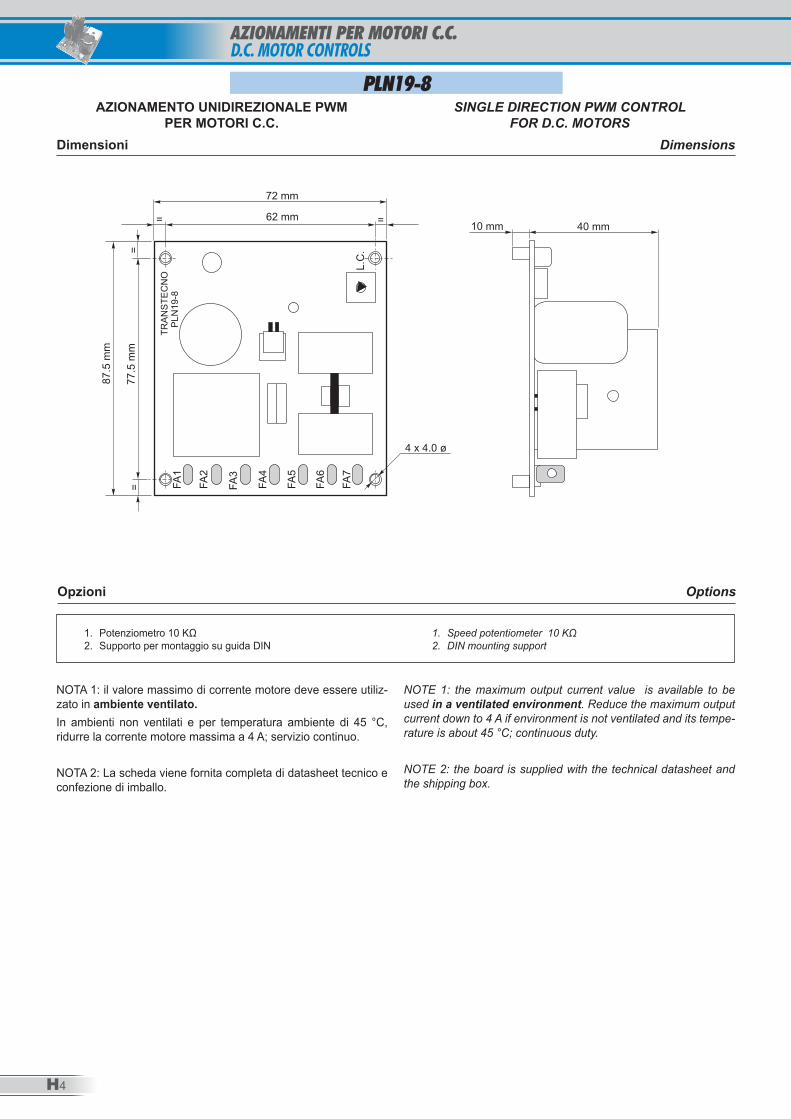
AZIONAMENTO UNIDIREZIONALE PWMPER MOTORI C.C.
SINGLE DIRECTION PWM CONTROLFOR D.C. MOTORS
Dimensioni Dimensions
Opzioni Options
1. Potenziometro 10 KΩ2. Supporto per montaggio su guida DIN
1. Speed potentiometer 10 KΩ2. DIN mounting support
NOTA 1: il valore massimo di corrente motore deve essere utiliz-zato in ambiente ventilato. In ambienti non ventilati e per temperatura ambiente di 45 °C, ridurre la corrente motore massima a 4 A; servizio continuo.
NOTA 2: La scheda viene fornita completa di datasheet tecnico e confezione di imballo.
NOTE 1: the maximum output current value is available to be used in a ventilated environment. Reduce the maximum output current down to 4 A if environment is not ventilated and its tempe-rature is about 45 °C; continuous duty.
NOTE 2: the board is supplied with the technical datasheet and the shipping box.
PLN19-8
AZIONAMENTI PER MOTORI C.C. D.C. MOTOR CONTROLS
H5
Drive
rs
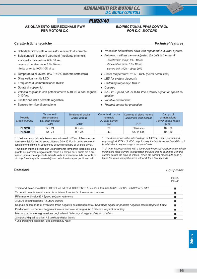
PLN20/40
● Scheda bidirezionale a transistor a ricircolo di corrente. ● Selezionabili i seguenti parametri (mediante trimmer):
- rampa di accelerazione: 0.5 - 10 sec - rampa di decelerazione: 0.5 - 10 sec - limite corrente 100%-30% circa
● Temperatura di lavoro: 0°C / +40°C (allarme sotto zero) ● Diagnostica tramite LED ● Frequenza di commutazione: 16kHz ● Dotata di coperchio ● Velocità regolabile con potenziometro 5-10 kΩ o con segnale
0-10 Vcc ● Limitazione della corrente regolabile ● Sensore termico di protezione
● Transistor bidirectional drive with regenerative current system. ● Following settings can be adjusted (by built in trimmers):
- acceleration ramp: 0.5 - 10 sec - deceleration ramp: 0.5 - 10 sec
- current limit 100% - about 30%
● Room temperature: 0°C / +40°C (alarm below zero) ● LED for system diagnosis ● Switching frequency: 16kHz ● Covered ● 5-10 kΩ Speed pot. or 0-10 Vdc external signal for speed re-
gulation ● Variable current limit ● Thermal sensor for protection
ModelloModel number
Tensione di alimentazione
DC input voltage[Vdc]
Tensione di uscitaMotor voltage
[Vdc]*
Corrente di uscita nominale
DC load current[A]
Corrente di picco motoreMaximum load current
[A]**
Campo di alimentazione
Power supply range[Vdc]
PLN20 12 ÷ 24 0 ÷ Vin 20 60 (4 sec) 10 ÷ 30PLN40 12 ÷24 0 ÷ Vin 40 120 (4 sec) 10 ÷ 30
Dotazioni Equipment
PLN20PLN40
Trimmer di selezione ACCEL, DECEL e LIMITE di CORRENTE / Selection Trimmer ACCEL, DECEL, CURRENT LIMIT ■2 contatti: marcia avanti e marcia indietro / 2 contacts : forward and reverse ■Riferimento di velocità / Speed setpoint reference ■3 LEDs di segnalazione / 3 LEDs signals ■Segnale di comando di eventuale freno negativo di stazionamento / Command signal for possible negative electromagnetic brake ■Predisposizione per montaggio a libro e a zoccolo / Arranged for 2 different ways of mounting ■Memorizzazione e segnalazione degli allarmi / Memory storage and report of allarm ■2 ingressi digitali ausiliari / 2 auxiliary digital inputs ■## uno impegnato dal reset / one comitted by reset
* L’azionamento riduce la tensione nominale di 1-2 Vcc. Il fenomeno è normale e fisiologico. Se serve ottenere 24 ÷ 12 Vcc in uscita sotto ogni condizione di carico, si suggerisce di sovralimentare di un paio di volt.** Un timer impone il limite con un andamento temporale iperbolico, cioè quanta più corrente eroga e tanto meno è il tempo per il quale ciò è am-messo, prima che appunto la scheda vada in limitazione. Alla corrente di picco (x 3 volte quella nominale) la scheda funziona per pochi secondi.
* The drive reduces the rated voltage of 1-2 Vdc. This is normal and physiological. If 24 ÷12 VDC output is required under all load conditions, it is advisable to supercharge a couple of volts.** A timer imposes a limit with a temporary hyperbolic performance, which means the more current is requested, the less time is permitted with this current before the drive is limited. When the current reaches its peak (3 times the rated value) the drive will work for a few seconds.
Caratteristiche tecniche Technical features
AZIONAMENTO BIDIREZIONALE PWMPER MOTORI C.C.
BIDIRECTIONAL PWM CONTROLFOR D.C. MOTORS
AZIONAMENTI PER MOTORI C.C.D.C. MOTOR CONTROLS
H6
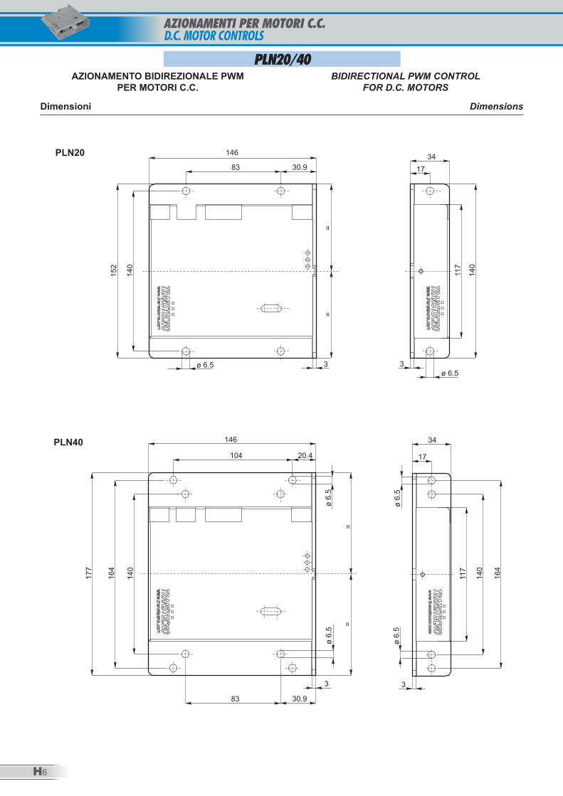
Dimensioni Dimensions
==
146
83 30.9
3 3ø 6.5
ø 6.5
34
17
152
140
140
117
146
104 20.4
30.983
3 3
177
164
140
140
117
164
==
34
17
ø 6
.5ø
6.5
ø 6
.5ø
6.5
PLN20
PLN40
PLN20/40AZIONAMENTO BIDIREZIONALE PWM
PER MOTORI C.C.BIDIRECTIONAL PWM CONTROL
FOR D.C. MOTORS
AZIONAMENTI PER MOTORI C.C. D.C. MOTOR CONTROLS
AZIONAMENTI PER MOTORI C.C. E BRUSHLESSD.C. AND BRUSHLESS MOTOR CONTROLS
H7
Drive
rs
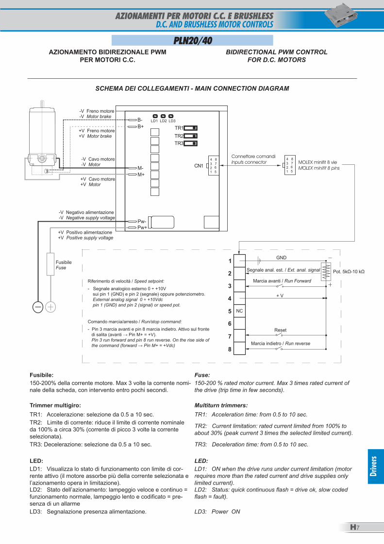
SCHEMA DEI COLLEGAMENTI - MAIN CONNECTION DIAGRAM
1
2
3
4
5
6
7
8
Marcia indietro / Run reverse
Marcia avanti / Run Forward
Fusibile
Fuse
Pw-
Pw+
M+
M-
B+
B- LD1 LD2 LD3
1 1
8 8
2 2
3 3
4 4
5 5
6 6
7 7
Connettore comandi
Inputs connector MOLEX minifit 8 vie
MOLEX minifit 8 pins
Pot. 5 -10 kΩkΩSegnale anal. est. / Ext. anal. signal
NC
+ V
Reset
GND
-V Freno motore
-V Motor brake
-V Negativo alimentazione
-V Negative supply voltage
+V Positivo alimentazione
+V Positive supply voltage
-V Cavo motore
-V Motor
+V Freno motore
+V Motor brake
+V Cavo motore
+V Motor
Riferimento di velocità / Speed setpoint:
- Segnale analogico esterno 0 ÷ +10V sui pin 1 (GND) e pin 2 (segnale) oppure potenziometro. External analog signal 0 ÷ +10Vdc pin 1 (GND) and pin 2 (signal) or speed pot.
Comando marcia/arresto / Run/stop command:
- Pin 3 marcia avanti e pin 8 marcia indietro. Attivo sul fronte di salita (avanti → Pin M+ = +V). Pin 3 run forward and pin 8 run reverse. On the rise side of the command (forward → Pin M+ = +Vdc)
Fusibile: Fuse:150-200% della corrente motore. Max 3 volte la corrente nomi-nale della scheda, con intervento entro pochi secondi.
150-200 % rated motor current. Max 3 times rated current of the drive (trip time in few seconds).
Trimmer multigiro: Multiturn trimmers: TR1: Accelerazione: selezione da 0.5 a 10 sec. TR1: Acceleration time: from 0.5 to 10 sec.TR2: Limite di corrente: riduce il limite di corrente nominale da 100% a circa 30% (corrente di picco 3 volte la corrente selezionata).
TR2: Current limitation: rated current limited from 100% to about 30% (peak current 3 times the selected limited current).
TR3: Decelerazione: selezione da 0.5 a 10 sec. TR3: Deceleration time: from 0.5 to 10 sec.
LED: LED: LD1: Visualizza lo stato di funzionamento con limite di cor-rente attivo (il motore assorbe più della corrente selezionata e l’azionamento opera in limitazione).
LD1: ON when the drive runs under current limitation (motor requires more than the rated current and drive supplies only limited current).
LD2: Stato dell’azionamento: lampeggio veloce e continuo = funzionamento normale, lampeggio lento e codificato = pre-senza di un allarme
LD2: Status: quick continuous flash = drive ok, slow coded flash = fault).
LD3: Segnalazione presenza alimentazione. LD3: Power ON
PLN20/40AZIONAMENTO BIDIREZIONALE PWM
PER MOTORI C.C.BIDIRECTIONAL PWM CONTROL
FOR D.C. MOTORS
H8
AZIONAMENTO PER MOTORI BRUSHLESSBRUSHLESS MOTORS CONTROLS
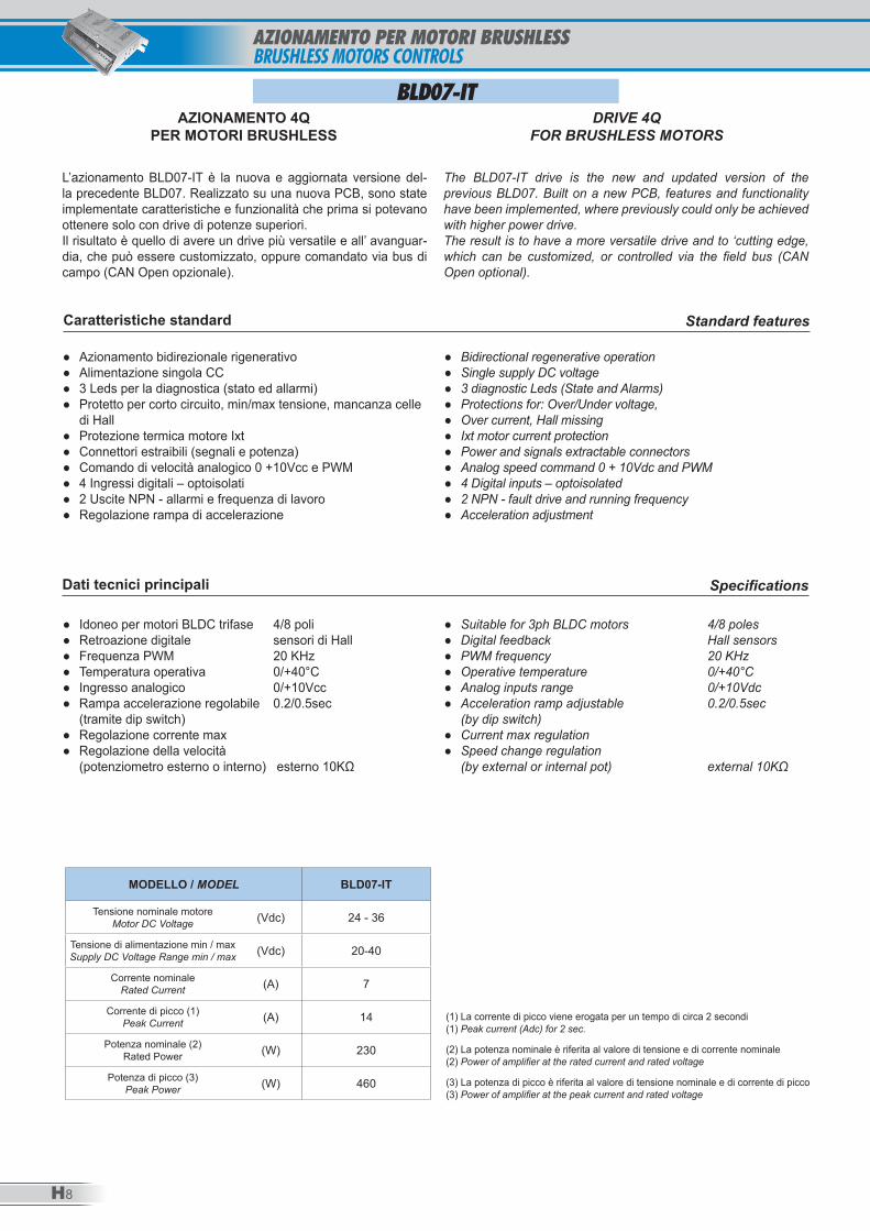
L’azionamento BLD07-IT è la nuova e aggiornata versione del-la precedente BLD07. Realizzato su una nuova PCB, sono state implementate caratteristiche e funzionalità che prima si potevano ottenere solo con drive di potenze superiori. Il risultato è quello di avere un drive più versatile e all’ avanguar-dia, che può essere customizzato, oppure comandato via bus di campo (CAN Open opzionale).
The BLD07-IT drive is the new and updated version of the previous BLD07. Built on a new PCB, features and functionality have been implemented, where previously could only be achieved with higher power drive. The result is to have a more versatile drive and to ‘cutting edge, which can be customized, or controlled via the field bus (CAN Open optional).
AZIONAMENTO 4QPER MOTORI BRUSHLESS
DRIVE 4QFOR BRUSHLESS MOTORS
BLD07-IT
Caratteristiche standard Standard features
● Azionamento bidirezionale rigenerativo ● Alimentazione singola CC ● 3 Leds per la diagnostica (stato ed allarmi) ● Protetto per corto circuito, min/max tensione, mancanza celle
di Hall ● Protezione termica motore Ixt ● Connettori estraibili (segnali e potenza) ● Comando di velocità analogico 0 +10Vcc e PWM ● 4 Ingressi digitali – optoisolati ● 2 Uscite NPN - allarmi e frequenza di lavoro ● Regolazione rampa di accelerazione
● Bidirectional regenerative operation ● Single supply DC voltage ● 3 diagnostic Leds (State and Alarms) ● Protections for: Over/Under voltage, ● Over current, Hall missing ● Ixt motor current protection ● Power and signals extractable connectors ● Analog speed command 0 + 10Vdc and PWM ● 4 Digital inputs – optoisolated ● 2 NPN - fault drive and running frequency ● Acceleration adjustment
Dati tecnici principali Specifications
● Idoneo per motori BLDC trifase 4/8 poli ● Retroazione digitale sensori di Hall ● Frequenza PWM 20 KHz ● Temperatura operativa 0/+40°C ● Ingresso analogico 0/+10Vcc ● Rampa accelerazione regolabile 0.2/0.5sec
(tramite dip switch) ● Regolazione corrente max ● Regolazione della velocità
(potenziometro esterno o interno) esterno 10KΩ
● Suitable for 3ph BLDC motors 4/8 poles ● Digital feedback Hall sensors ● PWM frequency 20 KHz ● Operative temperature 0/+40°C ● Analog inputs range 0/+10Vdc ● Acceleration ramp adjustable 0.2/0.5sec
(by dip switch) ● Current max regulation ● Speed change regulation
(by external or internal pot) external 10KΩ
MODELLO / MODEL BLD07-IT
Tensione nominale motoreMotor DC Voltage (Vdc) 24 - 36
Tensione di alimentazione min / maxSupply DC Voltage Range min / max (Vdc) 20-40
Corrente nominaleRated Current (A) 7
Corrente di picco (1)Peak Current (A) 14
Potenza nominale (2)Rated Power (W) 230
Potenza di picco (3)Peak Power (W) 460
(1) La corrente di picco viene erogata per un tempo di circa 2 secondi (1) Peak current (Adc) for 2 sec.
(2) La potenza nominale è riferita al valore di tensione e di corrente nominale (2) Power of amplifier at the rated current and rated voltage
(3) La potenza di picco è riferita al valore di tensione nominale e di corrente di picco (3) Power of amplifier at the peak current and rated voltage
H9
Drive
rs
AZIONAMENTO PER MOTORI BRUSHLESSBRUSHLESS MOTORS CONTROLS
BLD07-IT
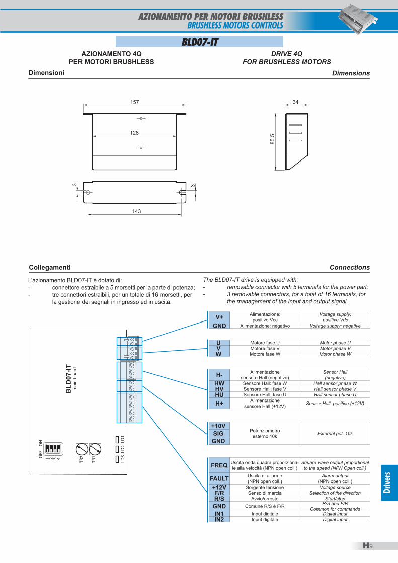
Dimensioni Dimensions
157
128
34
85.5
143
3 3
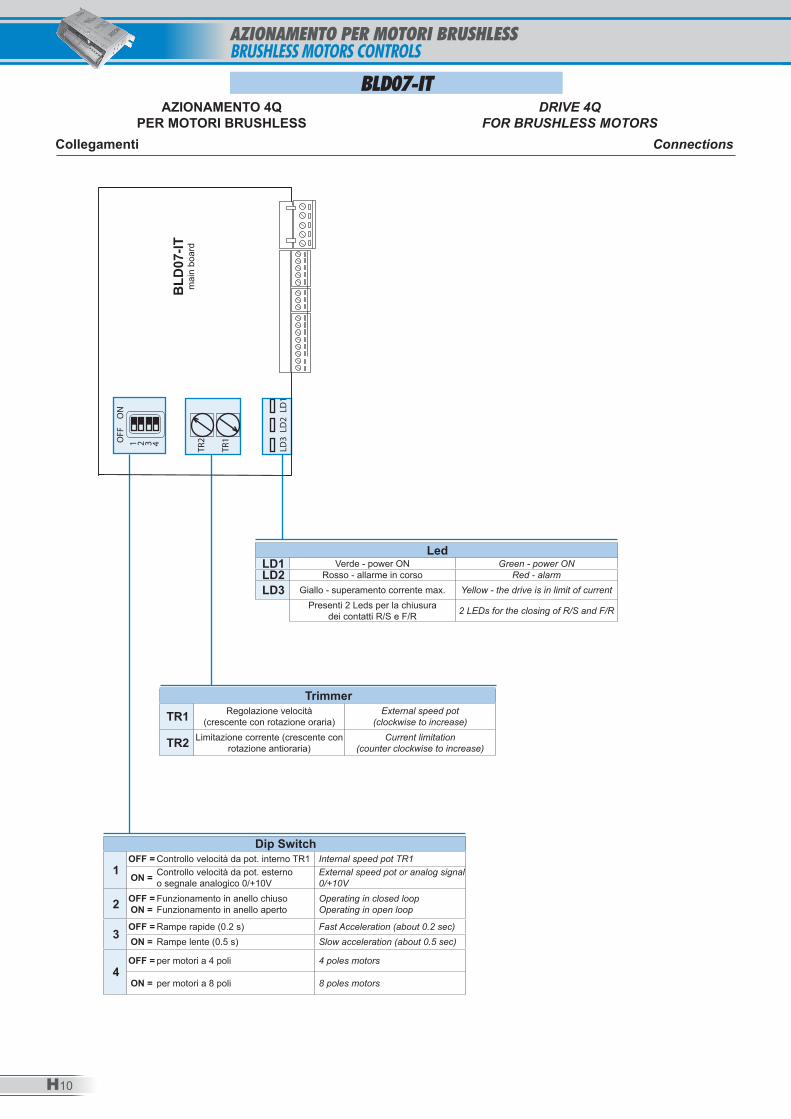
Collegamenti Connections
U Motore fase U Motor phase UV Motore fase V Motor phase VW Motore fase W Motor phase W
V+ Alimentazione:positivo Vcc
Voltage supply: positive Vdc
GND Alimentazione: negativo Voltage supply: negative
H- Alimentazionesensore Hall (negativo)
Sensor Hall (negative)
HW Sensore Hall: fase W Hall sensor phase WHV Sensore Hall: fase V Hall sensor phase VHU Sensore Hall: fase U Hall sensor phase U
H+ Alimentazionesensore Hall (+12V) Sensor Hall: positive (+12V)
OFF
ON
1 2 3 4
TR1
TR2
LD1
LD2
LD3
+10VPotenziometro
esterno 10k External pot. 10kSIGGND
FREQ Uscita onda quadra proporziona-le alla velocità (NPN open coll.)
Square wave output proportional to the speed (NPN Open coll.)
FAULT Uscita di allarme(NPN open coll.)
Alarm output(NPN open coll.)
+12V Sorgente tensione Voltage sourceF/R Senso di marcia Selection of the directionR/S Avvio/orresto Start/stop
GND Comune R/S e F/R R/S and F/R Common for commands
IN1 Input digitale Digital inputIN2 Input digitale Digital input
BLD
07-IT
mai
n bo
ard
L’azionamento BLD07-IT è dotato di:- connettore estraibile a 5 morsetti per la parte di potenza;- tre connettori estraibili, per un totale di 16 morsetti, per la gestione dei segnali in ingresso ed in uscita.
The BLD07-IT drive is equipped with: - removable connector with 5 terminals for the power part;- 3 removable connectors, for a total of 16 terminals, for the management of the input and output signal.
AZIONAMENTO 4QPER MOTORI BRUSHLESS
DRIVE 4QFOR BRUSHLESS MOTORS
H10
AZIONAMENTO PER MOTORI BRUSHLESSBRUSHLESS MOTORS CONTROLS
BLD07-IT
Collegamenti Connections
Dip Switch
1OFF = Controllo velocità da pot. interno TR1 Internal speed pot TR1
ON = Controllo velocità da pot. esterno o segnale analogico 0/+10V
External speed pot or analog signal 0/+10V
2 OFF =ON =
Funzionamento in anello chiusoFunzionamento in anello aperto
Operating in closed loopOperating in open loop
3 OFF = Rampe rapide (0.2 s) Fast Acceleration (about 0.2 sec)ON = Rampe lente (0.5 s) Slow acceleration (about 0.5 sec)
4OFF = per motori a 4 poli 4 poles motors
ON = per motori a 8 poli 8 poles motors
TrimmerTR1 Regolazione velocità
(crescente con rotazione oraria)External speed pot
(clockwise to increase)
TR2 Limitazione corrente (crescente con rotazione antioraria)
Current limitation (counter clockwise to increase)
LedLD1 Verde - power ON Green - power ONLD2 Rosso - allarme in corso Red - alarm
LD3 Giallo - superamento corrente max. Yellow - the drive is in limit of currentPresenti 2 Leds per la chiusura
dei contatti R/S e F/R 2 LEDs for the closing of R/S and F/R
OFF
ON
1 2 3 4
TR1
TR2
LD1
LD2
LD3
BLD
07-IT
mai
n bo
ard
AZIONAMENTO 4QPER MOTORI BRUSHLESS
DRIVE 4QFOR BRUSHLESS MOTORS
H11
Drive
rs
AZIONAMENTO PER MOTORI BRUSHLESSBRUSHLESS MOTOR CONTROLS
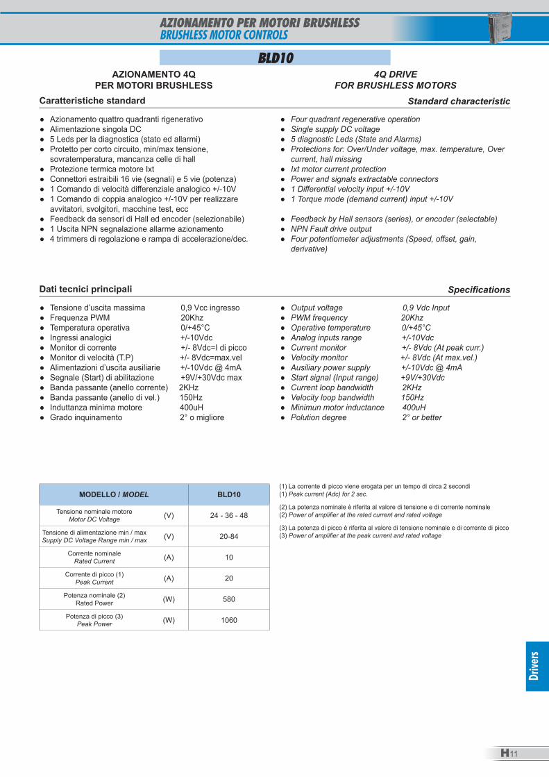
Caratteristiche standard Standard characteristic
● Azionamento quattro quadranti rigenerativo ● Alimentazione singola DC ● 5 Leds per la diagnostica (stato ed allarmi) ● Protetto per corto circuito, min/max tensione,
sovratemperatura, mancanza celle di hall ● Protezione termica motore Ixt ● Connettori estraibili 16 vie (segnali) e 5 vie (potenza) ● 1 Comando di velocità differenziale analogico +/-10V ● 1 Comando di coppia analogico +/-10V per realizzare
avvitatori, svolgitori, macchine test, ecc ● Feedback da sensori di Hall ed encoder (selezionabile) ● 1 Uscita NPN segnalazione allarme azionamento ● 4 trimmers di regolazione e rampa di accelerazione/dec.
● Four quadrant regenerative operation ● Single supply DC voltage ● 5 diagnostic Leds (State and Alarms) ● Protections for: Over/Under voltage, max. temperature, Over
current, hall missing ● Ixt motor current protection ● Power and signals extractable connectors ● 1 Differential velocity input +/-10V ● 1 Torque mode (demand current) input +/-10V
● Feedback by Hall sensors (series), or encoder (selectable) ● NPN Fault drive output ● Four potentiometer adjustments (Speed, offset, gain,
derivative)
Dati tecnici principali Specifications
● Tensione d’uscita massima 0,9 Vcc ingresso ● Frequenza PWM 20Khz ● Temperatura operativa 0/+45°C ● Ingressi analogici +/-10Vdc ● Monitor di corrente +/- 8Vdc=I di picco ● Monitor di velocità (T.P) +/- 8Vdc=max.vel ● Alimentazioni d’uscita ausiliarie +/-10Vdc @ 4mA ● Segnale (Start) di abilitazione +9V/+30Vdc max ● Banda passante (anello corrente) 2KHz ● Banda passante (anello di vel.) 150Hz ● Induttanza minima motore 400uH ● Grado inquinamento 2° o migliore
● Output voltage 0,9 Vdc Input ● PWM frequency 20Khz ● Operative temperature 0/+45°C ● Analog inputs range +/-10Vdc ● Current monitor +/- 8Vdc (At peak curr.) ● Velocity monitor +/- 8Vdc (At max.vel.) ● Ausiliary power supply +/-10Vdc @ 4mA ● Start signal (Input range) +9V/+30Vdc ● Current loop bandwidth 2KHz ● Velocity loop bandwidth 150Hz ● Minimun motor inductance 400uH ● Polution degree 2° or better
MODELLO / MODEL BLD10
Tensione nominale motoreMotor DC Voltage (V) 24 - 36 - 48
Tensione di alimentazione min / maxSupply DC Voltage Range min / max (V) 20-84
Corrente nominaleRated Current (A) 10
Corrente di picco (1)Peak Current (A) 20
Potenza nominale (2)Rated Power (W) 580
Potenza di picco (3)Peak Power (W) 1060
(1) La corrente di picco viene erogata per un tempo di circa 2 secondi (1) Peak current (Adc) for 2 sec.
(2) La potenza nominale è riferita al valore di tensione e di corrente nominale (2) Power of amplifier at the rated current and rated voltage
(3) La potenza di picco è riferita al valore di tensione nominale e di corrente di picco (3) Power of amplifier at the peak current and rated voltage
AZIONAMENTO 4QPER MOTORI BRUSHLESS
4Q DRIVEFOR BRUSHLESS MOTORS
BLD10
H12
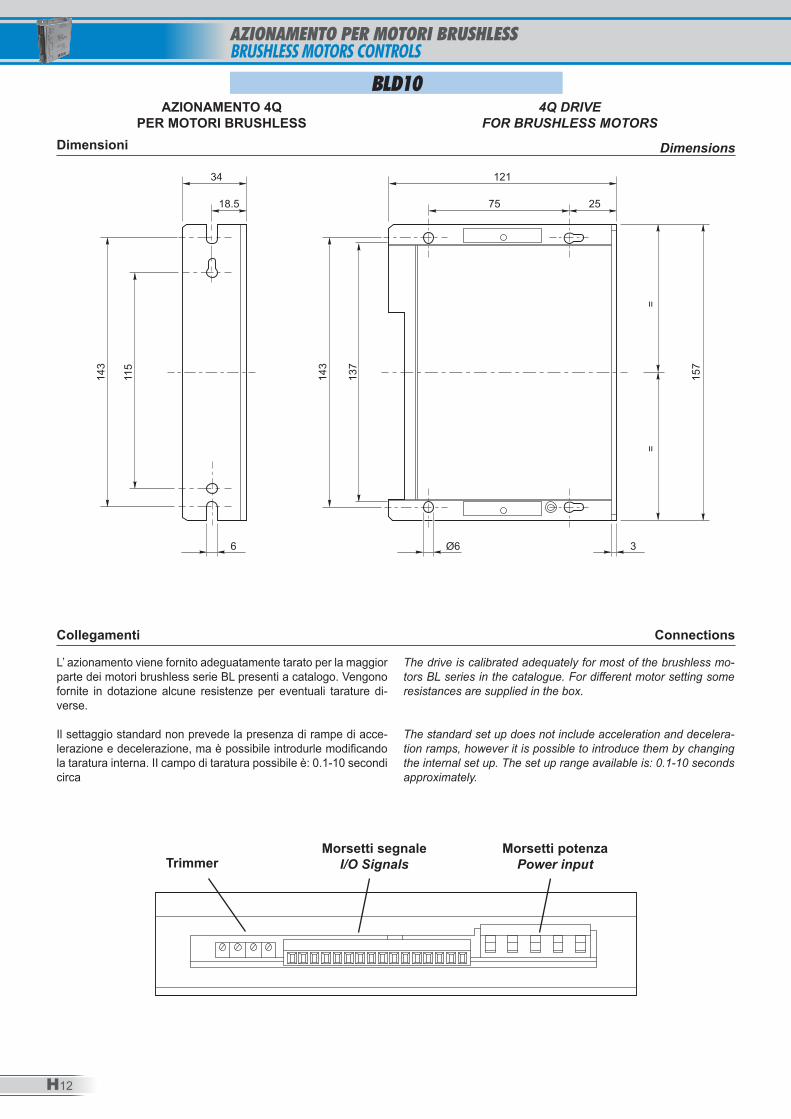
Dimensioni Dimensions
L’ azionamento viene fornito adeguatamente tarato per la maggior parte dei motori brushless serie BL presenti a catalogo. Vengono fornite in dotazione alcune resistenze per eventuali tarature di-verse.
Il settaggio standard non prevede la presenza di rampe di acce-lerazione e decelerazione, ma è possibile introdurle modificando la taratura interna. II campo di taratura possibile è: 0.1-10 secondi circa
The drive is calibrated adequately for most of the brushless mo-tors BL series in the catalogue. For different motor setting some resistances are supplied in the box.
The standard set up does not include acceleration and decelera-tion ramps, however it is possible to introduce them by changing the internal set up. The set up range available is: 0.1-10 seconds approximately.
ConnectionsCollegamenti
BLD10
121
75 2518.5
34
6 Ø6 3
143
115
137
143
157
==
AZIONAMENTO 4QPER MOTORI BRUSHLESS
4Q DRIVEFOR BRUSHLESS MOTORS
TrimmerMorsetti segnale
I/O SignalsMorsetti potenza
Power input
AZIONAMENTO PER MOTORI BRUSHLESSBRUSHLESS MOTORS CONTROLS
H13
Connections for brushless motors BL seriesCollegamenti per motori brushless serie BL
BLD10AZIONAMENTO 4Q
PER MOTORI BRUSHLESS4Q DRIVE
FOR BRUSHLESS MOTORS
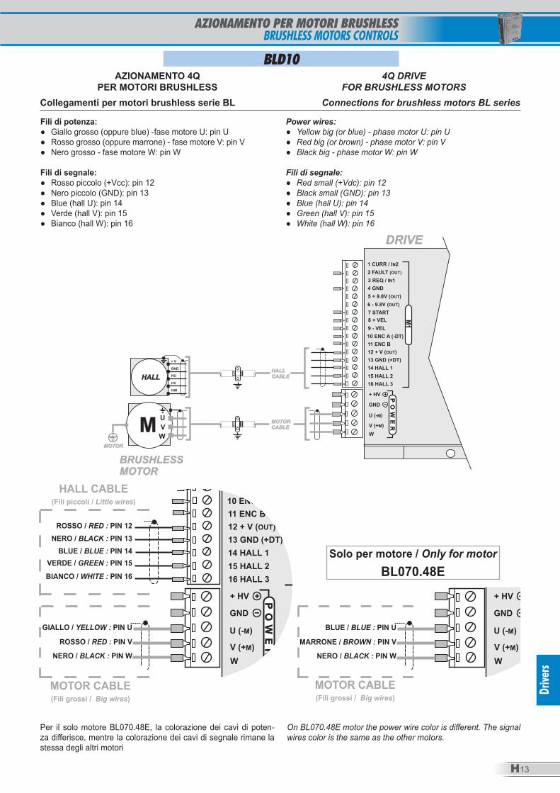
Fili di potenza: ● Giallo grosso (oppure blue) -fase motore U: pin U ● Rosso grosso (oppure marrone) - fase motore V: pin V ● Nero grosso - fase motore W: pin W
Fili di segnale: ● Rosso piccolo (+Vcc): pin 12 ● Nero piccolo (GND): pin 13 ● Blue (hall U): pin 14 ● Verde (hall V): pin 15 ● Bianco (hall W): pin 16
Power wires: ● Yellow big (or blue) - phase motor U: pin U ● Red big (or brown) - phase motor V: pin V ● Black big - phase motor W: pin W
Fili di segnale: ● Red small (+Vdc): pin 12 ● Black small (GND): pin 13 ● Blue (hall U): pin 14 ● Green (hall V): pin 15 ● White (hall W): pin 16
ROSSO / RED : PIN 12NERO / BLACK : PIN 13
BLUE / BLUE : PIN 14VERDE / GREEN : PIN 15BIANCO / WHITE : PIN 16
GIALLO / YELLOW : PIN U
ROSSO / RED : PIN V
NERO / BLACK : PIN W
HALL CABLE(Fili piccoli / Little wires)
MOTOR CABLE(Fili grossi / Big wires)
MOTOR CABLE(Fili grossi / Big wires)
BLUE / BLUE : PIN U
MARRONE / BROWN : PIN V
NERO / BLACK : PIN W
Solo per motore / Only for motorBL070.48E
Per il solo motore BL070.48E, la colorazione dei cavi di poten-za differisce, mentre la colorazione dei cavi di segnale rimane la stessa degli altri motori
On BL070.48E motor the power wire color is different. The signal wires color is the same as the other motors.
AZIONAMENTO PER MOTORI BRUSHLESSBRUSHLESS MOTORS CONTROLS
Drive
rs
H14
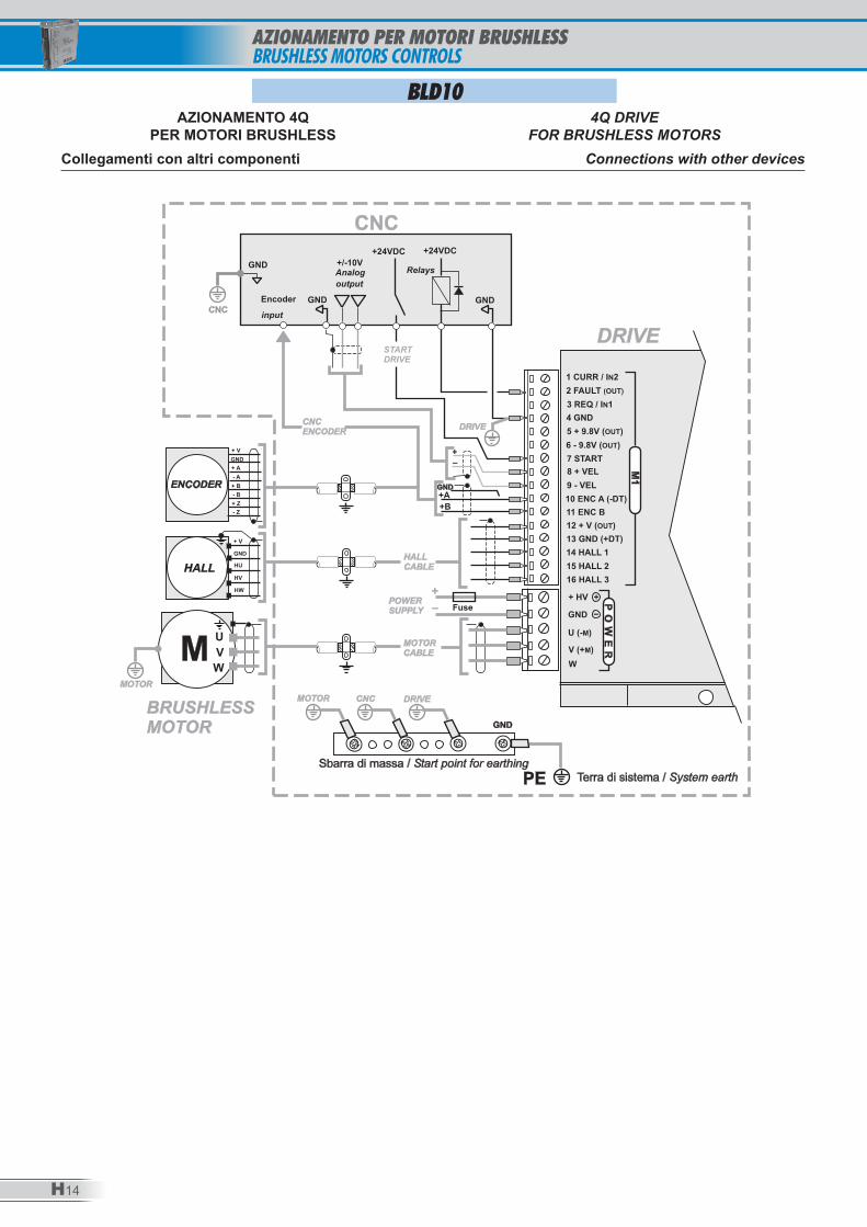
Connections with other devicesCollegamenti con altri componenti
BLD10AZIONAMENTO 4Q
PER MOTORI BRUSHLESS4Q DRIVE
FOR BRUSHLESS MOTORS
AZIONAMENTO PER MOTORI BRUSHLESSBRUSHLESS MOTORS CONTROLS
H15
Drive
rs
Brushless motor connectionCollegamenti per motori Brushless
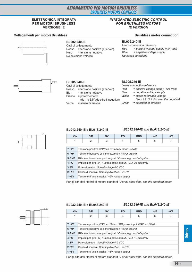
ELETTRONICA INTEGRATAPER MOTORI BRUSHLESS
VERSIONE IE
INTEGRATED ELECTRIC CONTROL FOR BRUSHLESS MOTORS
IE VERSION
BL002.240-IECavi di collegamentoRosso = tensione positiva (+24 Vcc)Nero = tensione negativaNo selezione velocità
BL002.240-IELeads connection referenceRed = positive voltage supply (+24 Vdc)Blue = negative voltage supplyNo speed selections
BL005.240-IE Cavi di collegamentoRosso = tensione positiva (+24 Vcc)Blu = tensione negativaBianco = potenziometro (da 1 a 3.5 Vdc oltre il negativo)Verde = senso di marcia
BL005.240-IE Leads connection referenceRed = positive voltage supply (+24 Vdc)Blue = negative voltage supplyWhite = speed reference voltage (from 1 to 3.5 Vdc over the negative)Green = selection of direction
+5v F/R SV PG GND -VP +VP1 2 3 4 5 6 7
7 +VP Tensione positiva +24Vcc / DC power input +24Vdc
6 -VP Tensione negativa di alimentazione / Power ground
5 GND Riferimento comune per i segnali / Common ground of system
4 PG Impulsi per giro (24) / Speed pulse output (TTL), 24 pulse/rev
3 SV Potenziometro / Speed voltage 0-5 VDC
2 F/R Senso di marcia / Rotating direction. Hi=CW
1 +5V Tensione 5 Vcc in uscita / +5V voltage output
BL012.240-IE e BL018.240-IE BL012.240-IE and BL018.240-IE
Per gli altri dati riferirsi al motore standard / For all other data, see the standard motor.
+5v F/R SV PG GND -VP +VP1 2 3 4 5 6 7
7 +VP Tensione positiva +24Vcc/+36Vcc / DC power input +24Vdc/+36Vdc
6 -VP Tensione negativa di alimentazione / Power ground
5 GND Riferimento comune per i segnali / Common ground of system
4 PG Impulsi per giro (12) / Speed pulse output (TTL), 12 pulse/rev
3 SV Potenziometro / Speed voltage 0-5 VDC
2 F/R Senso di marcia / Rotating direction. Hi=CW
1 +5V Tensione 5 Vcc in uscita / +5V voltage output
BL032.240-IE e BL043.240-IE BL032.240-IE and BL043.240-IE
Per gli altri dati riferirsi al motore standard / For all other data, see the standard motor.
AZIONAMENTO PER MOTORI BRUSHLESSBRUSHLESS MOTORS CONTROLS
TRANSTECNOmember of
group
w w w . i n t e c n o - s r l . c o m
INTECNO
TRANSTECNOmember of
group
INTECNO
20
14
MIC
RO G
earm
otor
s
MICROGearmotors


![Motoriduttori brushless CC combinati Brushless DC double ......US UD Simbologia n 1 [min-1] Velocità in ingresso / Input speed n 2 [min-1] Velocità in uscita / Output speed i Rapporto](https://static.fdocumenti.com/doc/165x107/5f494217fb5fef5ef209ca6f/motoriduttori-brushless-cc-combinati-brushless-dc-double-us-ud-simbologia.jpg)