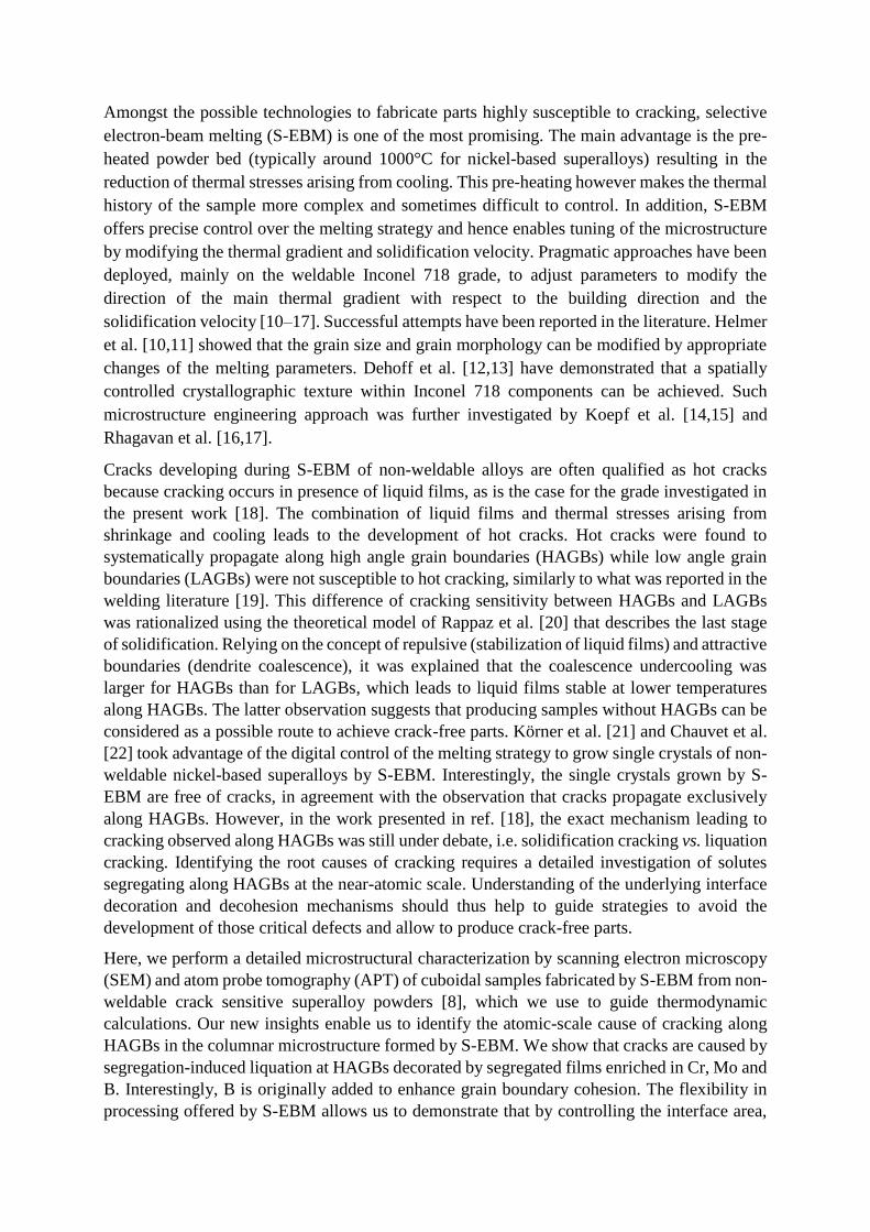
Atomic-scale grain boundary engineering to overcome hot ...
26
Atomic-scale grain boundary engineering to overcome hot-cracking in additively- manufactured superalloys Paraskevas Kontis 1* , Edouard Chauvet 2,3 , Zirong Peng 1 , Junyang He 1 , Alisson Kwiatkowski da Silva 1 , Dierk Raabe 1 , Catherine Tassin 2 , Jean-Jacques Blandin 2 , Stéphane Abed 3 , Rémy Dendievel 2 , Baptiste Gault 1,4 , Guilhem Martin 2* 1 Max-Planck-Institut für Eisenforschung, Max-Planck-Str. 1, 40237 Düsseldorf, Germany. 2 Univ. Grenoble Alpes, CNRS, Grenoble INP, SIMaP, F-38000 Grenoble, France. 3 Poly-Shape, 235 Rue des Canesteu -ZI La Gandonne, 13300, Salon-de-Provence, France. 4 Department of Materials, Imperial College London, South Kensington, SW7 2AZ, UK. Abstract There are still debates regarding the mechanisms that lead to hot cracking in parts build by additive manufacturing (AM) of non-weldable nickel-based superalloys. This lack of in-depth understanding of the root causes of hot cracking is an impediment to designing engineering parts for safety-critical applications. Here, we deploy a near-atomic-scale approach to investigate the details of the compositional decoration of grain boundaries in the coarse-grained, columnar microstructure in parts built from a non-weldable nickel-based superalloy by selective electron-beam melting. The progressive enrichment in Cr, Mo and B at grain boundaries over the course of the AM-typical successive solidification and remelting events, accompanied by solid-state diffusion, causes grain boundary segregation induced liquation. This observation is consistent with thermodynamic calculations. We demonstrate that by adjusting build parameters to obtain a fine-grained equiaxed or a columnar microstructure with grain width smaller than 100 μm enables to avoid cracking, despite strong grain boundary segregation. We find that the spread of critical solutes to a higher total interfacial area, combined with lower thermal stresses, helps to suppress interfacial liquation. Keywords: Hot cracking, grain boundaries, electron beam melting, superalloys, liquid film * Corresponding authors: [email protected], [email protected] 1 Introduction Additive manufacturing (AM) has a great potential for the production of novel engineering components for aerospace and power generation applications, where nickel-based superalloys are predominantly used [1]. However, it is very challenging to produce safety-critical components by AM with zero-crack tolerance, yet the digitalisation inherent to AM promises large gains in manufacturing and repair efficiency [2]. The AM community currently invests great efforts to 3D print well-known superalloys compositions considered as non-weldable such as IN738 [3–5], CMSX-4 [6], CM247LC [7] among others [8,9]. These alloy grades, which have been classified as non-weldable due to their Ti and Al contents [2] usually imply formation of large volume fractions of γ'-precipitates and were observed to undergo severe cracking when welded or AM built.
Transcript of Atomic-scale grain boundary engineering to overcome hot ...

Atomic-scale grain boundary engineering to overcome hot-cracking in additively-
manufactured superalloys Paraskevas Kontis1*, Edouard Chauvet2,3, Zirong Peng1, Junyang He1, Alisson Kwiatkowski da
Silva1, Dierk Raabe1, Catherine Tassin2, Jean-Jacques Blandin2, Stéphane Abed3, Rémy
Dendievel2, Baptiste Gault1,4, Guilhem Martin2*
1 Max-Planck-Institut für Eisenforschung, Max-Planck-Str. 1, 40237 Düsseldorf, Germany.
2 Univ. Grenoble Alpes, CNRS, Grenoble INP, SIMaP, F-38000 Grenoble, France.
3 Poly-Shape, 235 Rue des Canesteu -ZI La Gandonne, 13300, Salon-de-Provence, France.
4 Department of Materials, Imperial College London, South Kensington, SW7 2AZ, UK.
Abstract
There are still debates regarding the mechanisms that lead to hot cracking in parts build by
additive manufacturing (AM) of non-weldable nickel-based superalloys. This lack of in-depth
understanding of the root causes of hot cracking is an impediment to designing engineering
parts for safety-critical applications. Here, we deploy a near-atomic-scale approach to
investigate the details of the compositional decoration of grain boundaries in the coarse-grained,
columnar microstructure in parts built from a non-weldable nickel-based superalloy by selective
electron-beam melting. The progressive enrichment in Cr, Mo and B at grain boundaries over
the course of the AM-typical successive solidification and remelting events, accompanied by
solid-state diffusion, causes grain boundary segregation induced liquation. This observation is
consistent with thermodynamic calculations. We demonstrate that by adjusting build
parameters to obtain a fine-grained equiaxed or a columnar microstructure with grain width
smaller than 100 μm enables to avoid cracking, despite strong grain boundary segregation. We
find that the spread of critical solutes to a higher total interfacial area, combined with lower
thermal stresses, helps to suppress interfacial liquation.
Keywords: Hot cracking, grain boundaries, electron beam melting, superalloys, liquid film
* Corresponding authors: [email protected], [email protected]
1 Introduction
Additive manufacturing (AM) has a great potential for the production of novel engineering
components for aerospace and power generation applications, where nickel-based superalloys
are predominantly used [1]. However, it is very challenging to produce safety-critical
components by AM with zero-crack tolerance, yet the digitalisation inherent to AM promises
large gains in manufacturing and repair efficiency [2]. The AM community currently invests
great efforts to 3D print well-known superalloys compositions considered as non-weldable such
as IN738 [3–5], CMSX-4 [6], CM247LC [7] among others [8,9]. These alloy grades, which
have been classified as non-weldable due to their Ti and Al contents [2] usually imply formation
of large volume fractions of γ'-precipitates and were observed to undergo severe cracking when
welded or AM built.
Amongst the possible technologies to fabricate parts highly susceptible to cracking, selective
electron-beam melting (S-EBM) is one of the most promising. The main advantage is the pre-
heated powder bed (typically around 1000°C for nickel-based superalloys) resulting in the
reduction of thermal stresses arising from cooling. This pre-heating however makes the thermal
history of the sample more complex and sometimes difficult to control. In addition, S-EBM
offers precise control over the melting strategy and hence enables tuning of the microstructure
by modifying the thermal gradient and solidification velocity. Pragmatic approaches have been
deployed, mainly on the weldable Inconel 718 grade, to adjust parameters to modify the
direction of the main thermal gradient with respect to the building direction and the
solidification velocity [10–17]. Successful attempts have been reported in the literature. Helmer
et al. [10,11] showed that the grain size and grain morphology can be modified by appropriate
changes of the melting parameters. Dehoff et al. [12,13] have demonstrated that a spatially
controlled crystallographic texture within Inconel 718 components can be achieved. Such
microstructure engineering approach was further investigated by Koepf et al. [14,15] and
Rhagavan et al. [16,17].
Cracks developing during S-EBM of non-weldable alloys are often qualified as hot cracks
because cracking occurs in presence of liquid films, as is the case for the grade investigated in
the present work [18]. The combination of liquid films and thermal stresses arising from
shrinkage and cooling leads to the development of hot cracks. Hot cracks were found to
systematically propagate along high angle grain boundaries (HAGBs) while low angle grain
boundaries (LAGBs) were not susceptible to hot cracking, similarly to what was reported in the
welding literature [19]. This difference of cracking sensitivity between HAGBs and LAGBs
was rationalized using the theoretical model of Rappaz et al. [20] that describes the last stage
of solidification. Relying on the concept of repulsive (stabilization of liquid films) and attractive
boundaries (dendrite coalescence), it was explained that the coalescence undercooling was
larger for HAGBs than for LAGBs, which leads to liquid films stable at lower temperatures
along HAGBs. The latter observation suggests that producing samples without HAGBs can be
considered as a possible route to achieve crack-free parts. Körner et al. [21] and Chauvet et al.
[22] took advantage of the digital control of the melting strategy to grow single crystals of non-
weldable nickel-based superalloys by S-EBM. Interestingly, the single crystals grown by S-
EBM are free of cracks, in agreement with the observation that cracks propagate exclusively
along HAGBs. However, in the work presented in ref. [18], the exact mechanism leading to
cracking observed along HAGBs was still under debate, i.e. solidification cracking vs. liquation
cracking. Identifying the root causes of cracking requires a detailed investigation of solutes
segregating along HAGBs at the near-atomic scale. Understanding of the underlying interface
decoration and decohesion mechanisms should thus help to guide strategies to avoid the
development of those critical defects and allow to produce crack-free parts.
Here, we perform a detailed microstructural characterization by scanning electron microscopy
(SEM) and atom probe tomography (APT) of cuboidal samples fabricated by S-EBM from non-
weldable crack sensitive superalloy powders [8], which we use to guide thermodynamic
calculations. Our new insights enable us to identify the atomic-scale cause of cracking along
HAGBs in the columnar microstructure formed by S-EBM. We show that cracks are caused by
segregation-induced liquation at HAGBs decorated by segregated films enriched in Cr, Mo and
B. Interestingly, B is originally added to enhance grain boundary cohesion. The flexibility in
processing offered by S-EBM allows us to demonstrate that by controlling the interface area,
in particular the grain boundary density, we can limit solute enrichment in the intergranular
region and prevent critical liquation, alleviating cracking susceptibility. Increasing drastically
the interface area not only helps to limit solute enrichment at HAGBs but also to contribute to
better distribute thermal stresses that act as the mechanical driving force for hot cracking. This
grain boundary engineering strategy is demonstrated in two new crack-free builds, respectively
exhibiting an equiaxed and a fine-columnar microstructure (grain width < 100 μm). Shedding
light on fundamental aspects of cracking allows us to derive atomic-scale inspired digital
metallurgy design pathways to enable application of these alloys in safety-critical applications,
such as blades in aero-engines.
2 Experimental procedures
2.1 Powder characteristics
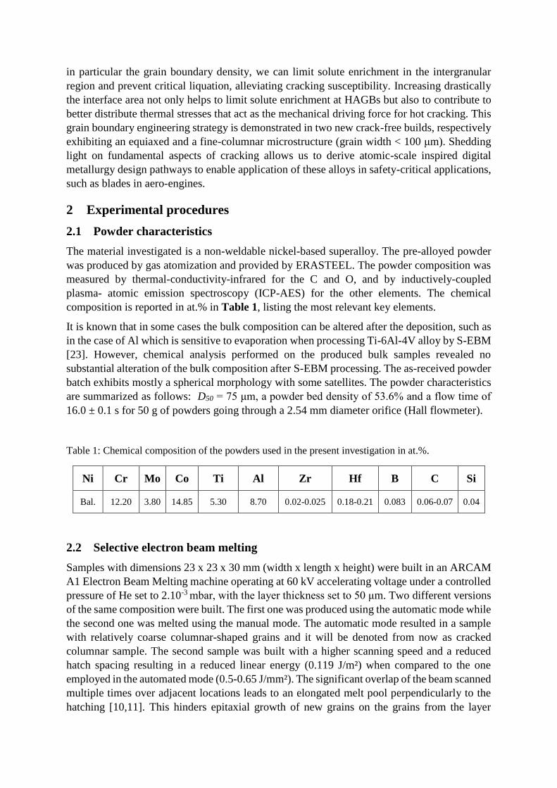
The material investigated is a non-weldable nickel-based superalloy. The pre-alloyed powder
was produced by gas atomization and provided by ERASTEEL. The powder composition was
measured by thermal-conductivity-infrared for the C and O, and by inductively-coupled
plasma- atomic emission spectroscopy (ICP-AES) for the other elements. The chemical
composition is reported in at.% in Table 1, listing the most relevant key elements.
It is known that in some cases the bulk composition can be altered after the deposition, such as
in the case of Al which is sensitive to evaporation when processing Ti-6Al-4V alloy by S-EBM
[23]. However, chemical analysis performed on the produced bulk samples revealed no
substantial alteration of the bulk composition after S-EBM processing. The as-received powder
batch exhibits mostly a spherical morphology with some satellites. The powder characteristics
are summarized as follows: D50 = 75 μm, a powder bed density of 53.6% and a flow time of
16.0 ± 0.1 s for 50 g of powders going through a 2.54 mm diameter orifice (Hall flowmeter).
Table 1: Chemical composition of the powders used in the present investigation in at.%.
Ni Cr Mo Co Ti Al Zr Hf B C Si
Bal. 12.20 3.80 14.85 5.30 8.70 0.02-0.025 0.18-0.21 0.083 0.06-0.07 0.04
2.2 Selective electron beam melting
Samples with dimensions 23 x 23 x 30 mm (width x length x height) were built in an ARCAM
A1 Electron Beam Melting machine operating at 60 kV accelerating voltage under a controlled
pressure of He set to 2.10-3 mbar, with the layer thickness set to 50 μm. Two different versions
of the same composition were built. The first one was produced using the automatic mode while
the second one was melted using the manual mode. The automatic mode resulted in a sample
with relatively coarse columnar-shaped grains and it will be denoted from now as cracked
columnar sample. The second sample was built with a higher scanning speed and a reduced
hatch spacing resulting in a reduced linear energy (0.119 J/m²) when compared to the one
employed in the automated mode (0.5-0.65 J/mm²). The significant overlap of the beam scanned
multiple times over adjacent locations leads to an elongated melt pool perpendicularly to the
hatching [10,11]. This hinders epitaxial growth of new grains on the grains from the layer
underneath and leads to an equiaxed microstructure [11,24]. This sample is denoted as crack-
free with equiaxed grains. All the used processing conditions were preliminary optimized to
achieve dense samples (density >99.8%) with no lack-of-fusion defects. Table 2 summarizes
the main parameters used to build the two samples. The building direction is denoted as Z.
A build plate made of a polycrystalline hot-rolled 10 mm thick stainless steel plate, grade EN
1.4307 was used during the production of all the samples. Although, its mechanical resistance
i.e. creep, is sufficient to allow us to run stable builds, after depositing the samples it was
slightly deformed. Diffusion between the substrate and the deposited material likely occurs over
limited distance, however in this study only the upper parts of the samples were investigated
which are not affected by this diffusion.
In each case, the build plate was heated at 1050°C and the preheating temperature was
maintained at 1050°C throughout the build and the focus offset set to 20 mA during the melting
steps. When operated in automatic mode, the melting parameters, such as caused by the beam
power and the scanning speed, were adjusted as a function of the geometry through the use of
automated functions such as the speed function or turning point function into the software EBM
Control 3.2, see Table 2 for more details. In the case of the manual mode, the power and scan
speed were imposed and do not depend on the geometry. In both cases, the melting strategy
consisted in scanning the area defined by the CAD in a snake-like manner with a line order set
to 1 and the scanning direction was also rotated by 90° after every layer.
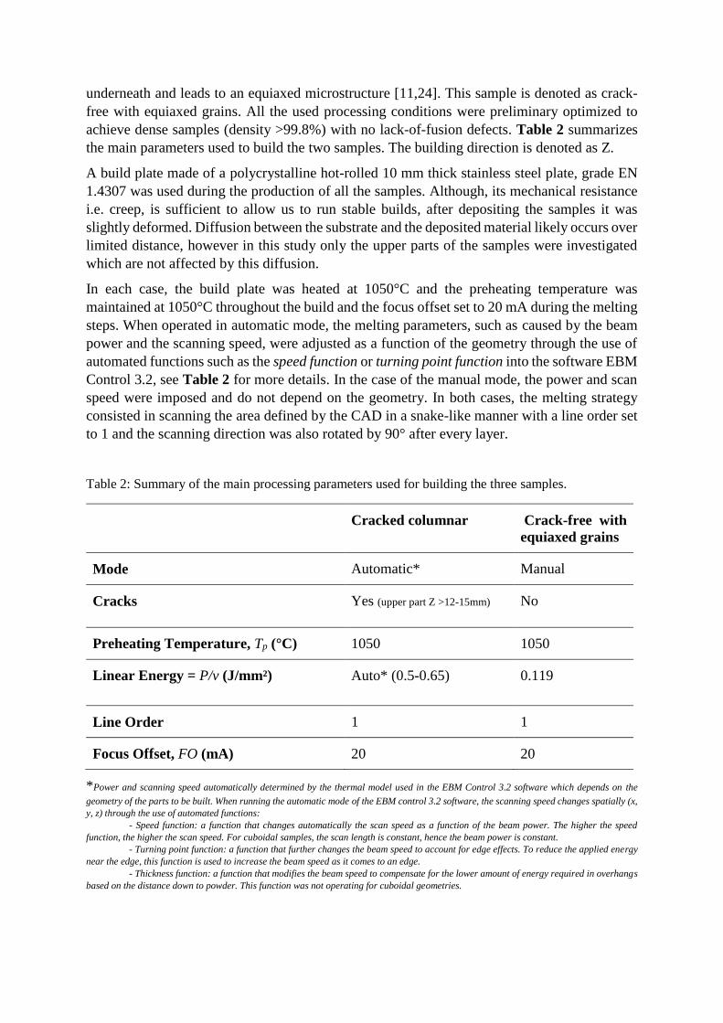
Table 2: Summary of the main processing parameters used for building the three samples.
Cracked columnar Crack-free with
equiaxed grains
Mode Automatic* Manual
Cracks Yes (upper part Z >12-15mm) No
Preheating Temperature, Tp (°C) 1050 1050
Linear Energy = P/v (J/mm²) Auto* (0.5-0.65) 0.119
Line Order 1 1
Focus Offset, FO (mA) 20 20
*Power and scanning speed automatically determined by the thermal model used in the EBM Control 3.2 software which depends on the
geometry of the parts to be built. When running the automatic mode of the EBM control 3.2 software, the scanning speed changes spatially (x,
y, z) through the use of automated functions:
- Speed function: a function that changes automatically the scan speed as a function of the beam power. The higher the speed
function, the higher the scan speed. For cuboidal samples, the scan length is constant, hence the beam power is constant.
- Turning point function: a function that further changes the beam speed to account for edge effects. To reduce the applied energy
near the edge, this function is used to increase the beam speed as it comes to an edge.
- Thickness function: a function that modifies the beam speed to compensate for the lower amount of energy required in overhangs
based on the distance down to powder. This function was not operating for cuboidal geometries.
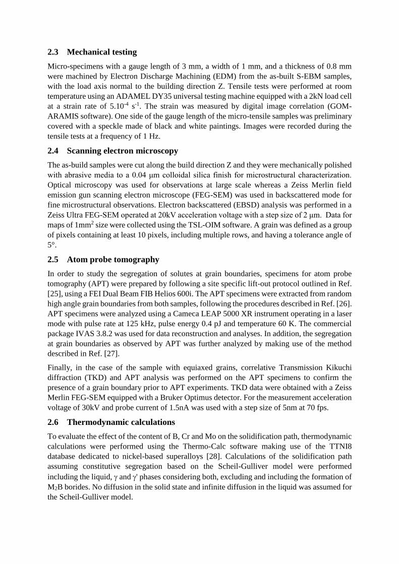
2.3 Mechanical testing
Micro-specimens with a gauge length of 3 mm, a width of 1 mm, and a thickness of 0.8 mm
were machined by Electron Discharge Machining (EDM) from the as-built S-EBM samples,
with the load axis normal to the building direction Z. Tensile tests were performed at room
temperature using an ADAMEL DY35 universal testing machine equipped with a 2kN load cell
at a strain rate of 5.10-4 s-1. The strain was measured by digital image correlation (GOM-
ARAMIS software). One side of the gauge length of the micro-tensile samples was preliminary
covered with a speckle made of black and white paintings. Images were recorded during the
tensile tests at a frequency of 1 Hz.
2.4 Scanning electron microscopy
The as-build samples were cut along the build direction Z and they were mechanically polished
with abrasive media to a 0.04 μm colloidal silica finish for microstructural characterization.
Optical microscopy was used for observations at large scale whereas a Zeiss Merlin field
emission gun scanning electron microscope (FEG-SEM) was used in backscattered mode for
fine microstructural observations. Electron backscattered (EBSD) analysis was performed in a
Zeiss Ultra FEG-SEM operated at 20kV acceleration voltage with a step size of 2 μm. Data for
maps of 1mm2 size were collected using the TSL-OIM software. A grain was defined as a group
of pixels containing at least 10 pixels, including multiple rows, and having a tolerance angle of
5°.
2.5 Atom probe tomography
In order to study the segregation of solutes at grain boundaries, specimens for atom probe
tomography (APT) were prepared by following a site specific lift-out protocol outlined in Ref.
[25], using a FEI Dual Beam FIB Helios 600i. The APT specimens were extracted from random
high angle grain boundaries from both samples, following the procedures described in Ref. [26].
APT specimens were analyzed using a Cameca LEAP 5000 XR instrument operating in a laser
mode with pulse rate at 125 kHz, pulse energy 0.4 pJ and temperature 60 K. The commercial
package IVAS 3.8.2 was used for data reconstruction and analyses. In addition, the segregation
at grain boundaries as observed by APT was further analyzed by making use of the method
described in Ref. [27].
Finally, in the case of the sample with equiaxed grains, correlative Transmission Kikuchi
diffraction (TKD) and APT analysis was performed on the APT specimens to confirm the
presence of a grain boundary prior to APT experiments. TKD data were obtained with a Zeiss
Merlin FEG-SEM equipped with a Bruker Optimus detector. For the measurement acceleration
voltage of 30kV and probe current of 1.5nA was used with a step size of 5nm at 70 fps.
2.6 Thermodynamic calculations
To evaluate the effect of the content of B, Cr and Mo on the solidification path, thermodynamic
calculations were performed using the Thermo-Calc software making use of the TTNI8
database dedicated to nickel-based superalloys [28]. Calculations of the solidification path
assuming constitutive segregation based on the Scheil-Gulliver model were performed
including the liquid, and ' phases considering both, excluding and including the formation of
M2B borides. No diffusion in the solid state and infinite diffusion in the liquid was assumed for
the Scheil-Gulliver model.
3 Results
3.1 Microstructural characterization: cracked columnar sample
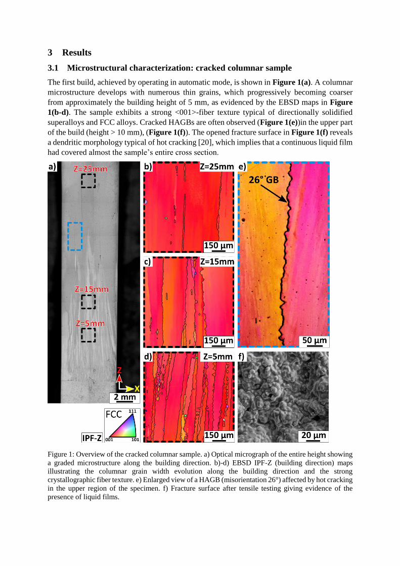
The first build, achieved by operating in automatic mode, is shown in Figure 1(a). A columnar
microstructure develops with numerous thin grains, which progressively becoming coarser
from approximately the building height of 5 mm, as evidenced by the EBSD maps in Figure
1(b-d). The sample exhibits a strong <001>-fiber texture typical of directionally solidified
superalloys and FCC alloys. Cracked HAGBs are often observed (Figure 1(e))in the upper part
of the build (height > 10 mm), (Figure 1(f)). The opened fracture surface in Figure 1(f) reveals
a dendritic morphology typical of hot cracking [20], which implies that a continuous liquid film
had covered almost the sample’s entire cross section.
Figure 1: Overview of the cracked columnar sample. a) Optical micrograph of the entire height showing
a graded microstructure along the building direction. b)-d) EBSD IPF-Z (building direction) maps
illustrating the columnar grain width evolution along the building direction and the strong
crystallographic fiber texture. e) Enlarged view of a HAGB (misorientation 26°) affected by hot cracking
in the upper region of the specimen. f) Fracture surface after tensile testing giving evidence of the
presence of liquid films.
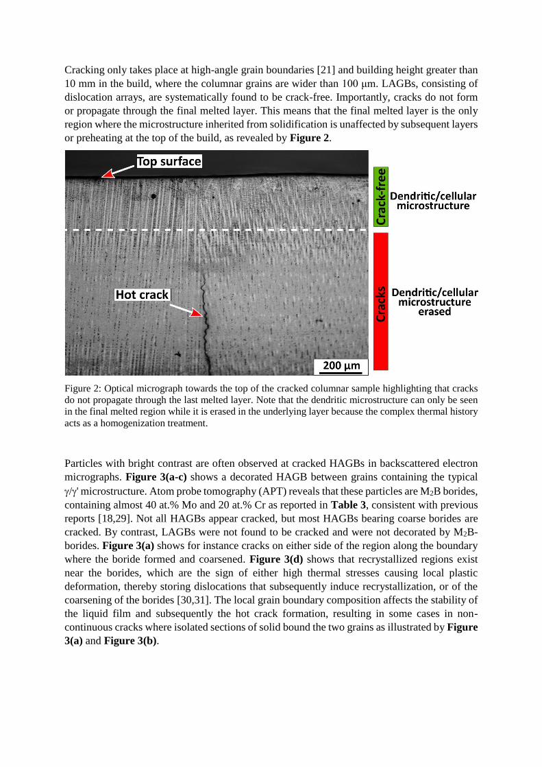
Cracking only takes place at high-angle grain boundaries [21] and building height greater than
10 mm in the build, where the columnar grains are wider than 100 μm. LAGBs, consisting of
dislocation arrays, are systematically found to be crack-free. Importantly, cracks do not form
or propagate through the final melted layer. This means that the final melted layer is the only
region where the microstructure inherited from solidification is unaffected by subsequent layers
or preheating at the top of the build, as revealed by Figure 2.
Figure 2: Optical micrograph towards the top of the cracked columnar sample highlighting that cracks
do not propagate through the last melted layer. Note that the dendritic microstructure can only be seen
in the final melted region while it is erased in the underlying layer because the complex thermal history
acts as a homogenization treatment.
Particles with bright contrast are often observed at cracked HAGBs in backscattered electron
micrographs. Figure 3(a-c) shows a decorated HAGB between grains containing the typical
/' microstructure. Atom probe tomography (APT) reveals that these particles are M2B borides,
containing almost 40 at.% Mo and 20 at.% Cr as reported in Table 3, consistent with previous
reports [18,29]. Not all HAGBs appear cracked, but most HAGBs bearing coarse borides are
cracked. By contrast, LAGBs were not found to be cracked and were not decorated by M2B-
borides. Figure 3(a) shows for instance cracks on either side of the region along the boundary
where the boride formed and coarsened. Figure 3(d) shows that recrystallized regions exist
near the borides, which are the sign of either high thermal stresses causing local plastic
deformation, thereby storing dislocations that subsequently induce recrystallization, or of the
coarsening of the borides [30,31]. The local grain boundary composition affects the stability of
the liquid film and subsequently the hot crack formation, resulting in some cases in non-
continuous cracks where isolated sections of solid bound the two grains as illustrated by Figure
3(a) and Figure 3(b).
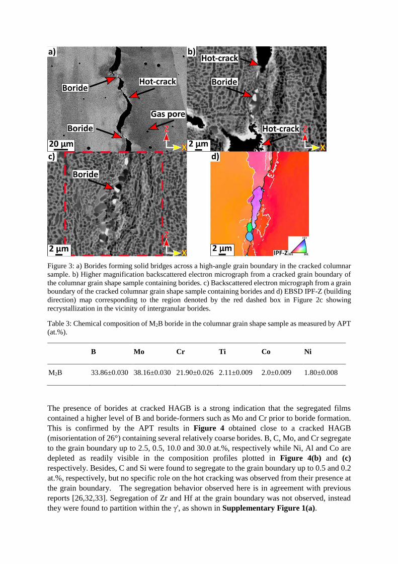
Figure 3: a) Borides forming solid bridges across a high-angle grain boundary in the cracked columnar
sample. b) Higher magnification backscattered electron micrograph from a cracked grain boundary of
the columnar grain shape sample containing borides. c) Backscattered electron micrograph from a grain
boundary of the cracked columnar grain shape sample containing borides and d) EBSD IPF-Z (building
direction) map corresponding to the region denoted by the red dashed box in Figure 2c showing
recrystallization in the vicinity of intergranular borides.
Table 3: Chemical composition of M2B boride in the columnar grain shape sample as measured by APT
(at.%).
B Mo Cr Ti Co Ni
M2B 33.86±0.030 38.16±0.030 21.90±0.026 2.11±0.009 2.0±0.009 1.80±0.008
The presence of borides at cracked HAGB is a strong indication that the segregated films
contained a higher level of B and boride-formers such as Mo and Cr prior to boride formation.
This is confirmed by the APT results in Figure 4 obtained close to a cracked HAGB
(misorientation of 26°) containing several relatively coarse borides. B, C, Mo, and Cr segregate
to the grain boundary up to 2.5, 0.5, 10.0 and 30.0 at.%, respectively while Ni, Al and Co are
depleted as readily visible in the composition profiles plotted in Figure 4(b) and (c)
respectively. Besides, C and Si were found to segregate to the grain boundary up to 0.5 and 0.2
at.%, respectively, but no specific role on the hot cracking was observed from their presence at
the grain boundary. The segregation behavior observed here is in agreement with previous
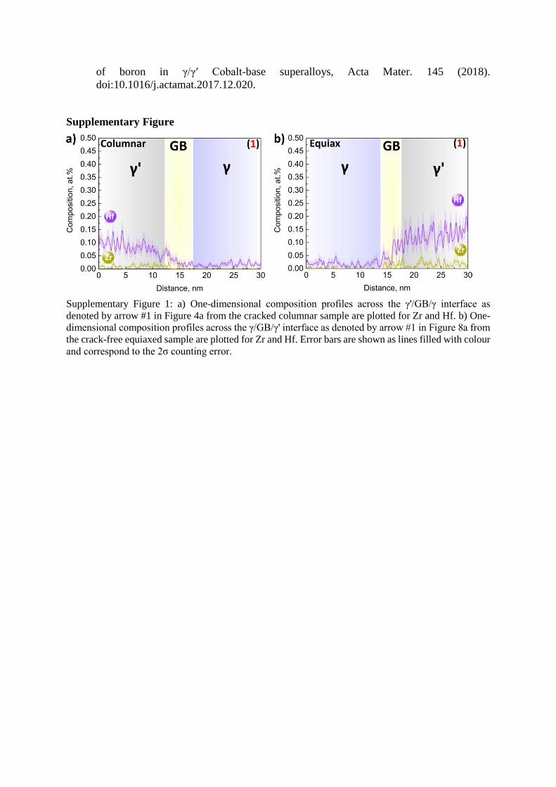
reports [26,32,33]. Segregation of Zr and Hf at the grain boundary was not observed, instead
they were found to partition within the γ', as shown in Supplementary Figure 1(a).
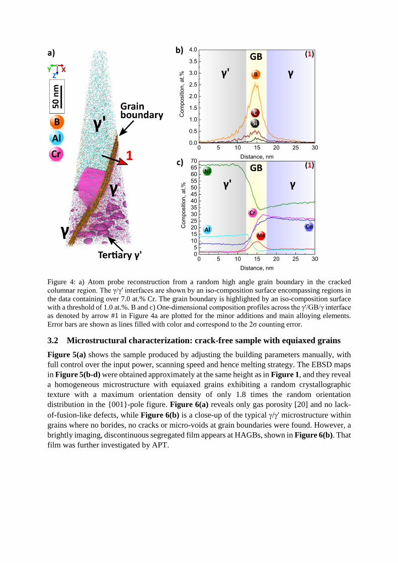
Figure 4: a) Atom probe reconstruction from a random high angle grain boundary in the cracked
columnar region. The γ/γ' interfaces are shown by an iso-composition surface encompassing regions in
the data containing over 7.0 at.% Cr. The grain boundary is highlighted by an iso-composition surface
with a threshold of 1.0 at.%. B and c) One-dimensional composition profiles across the γ'/GB/γ interface
as denoted by arrow #1 in Figure 4a are plotted for the minor additions and main alloying elements.
Error bars are shown as lines filled with color and correspond to the 2σ counting error.
3.2 Microstructural characterization: crack-free sample with equiaxed grains
Figure 5(a) shows the sample produced by adjusting the building parameters manually, with
full control over the input power, scanning speed and hence melting strategy. The EBSD maps
in Figure 5(b-d) were obtained approximately at the same height as in Figure 1, and they reveal
a homogeneous microstructure with equiaxed grains exhibiting a random crystallographic
texture with a maximum orientation density of only 1.8 times the random orientation
distribution in the {001}-pole figure. Figure 6(a) reveals only gas porosity [20] and no lack-
of-fusion-like defects, while Figure 6(b) is a close-up of the typical /' microstructure within
grains where no borides, no cracks or micro-voids at grain boundaries were found. However, a
brightly imaging, discontinuous segregated film appears at HAGBs, shown in Figure 6(b). That
film was further investigated by APT.
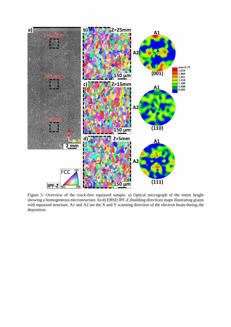
Figure 5: Overview of the crack-free equiaxed sample. a) Optical micrograph of the entire height
showing a homogeneous microstructure. b)-d) EBSD IPF-Z (building direction) maps illustrating grains
with equiaxed structure. A1 and A2 are the X and Y scanning direction of the electron beam during the
deposition.
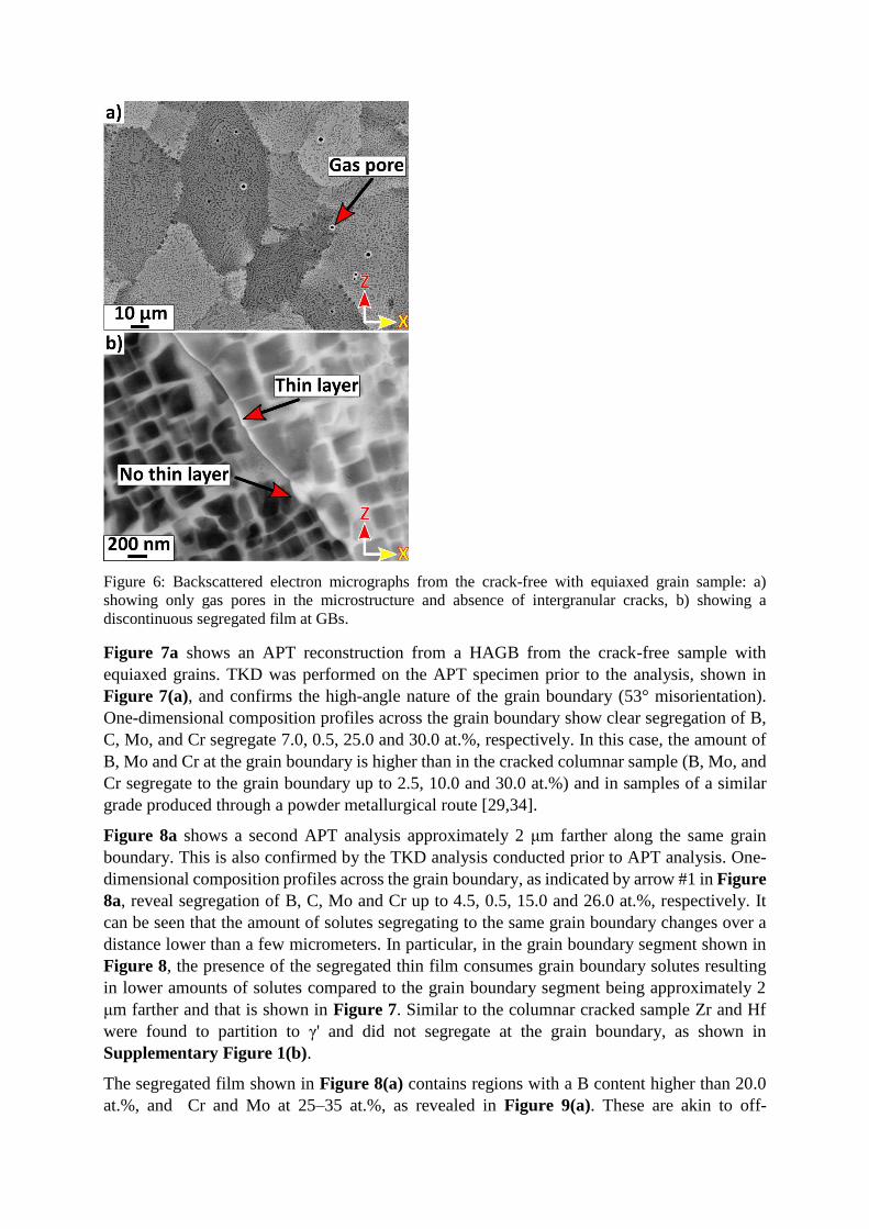
Figure 6: Backscattered electron micrographs from the crack-free with equiaxed grain sample: a)
showing only gas pores in the microstructure and absence of intergranular cracks, b) showing a
discontinuous segregated film at GBs.
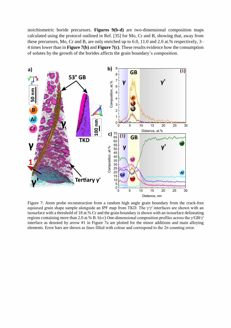
Figure 7a shows an APT reconstruction from a HAGB from the crack-free sample with
equiaxed grains. TKD was performed on the APT specimen prior to the analysis, shown in
Figure 7(a), and confirms the high-angle nature of the grain boundary (53° misorientation).
One-dimensional composition profiles across the grain boundary show clear segregation of B,
C, Mo, and Cr segregate 7.0, 0.5, 25.0 and 30.0 at.%, respectively. In this case, the amount of
B, Mo and Cr at the grain boundary is higher than in the cracked columnar sample (B, Mo, and
Cr segregate to the grain boundary up to 2.5, 10.0 and 30.0 at.%) and in samples of a similar
grade produced through a powder metallurgical route [29,34].
Figure 8a shows a second APT analysis approximately 2 μm farther along the same grain
boundary. This is also confirmed by the TKD analysis conducted prior to APT analysis. One-
dimensional composition profiles across the grain boundary, as indicated by arrow #1 in Figure
8a, reveal segregation of B, C, Mo and Cr up to 4.5, 0.5, 15.0 and 26.0 at.%, respectively. It
can be seen that the amount of solutes segregating to the same grain boundary changes over a
distance lower than a few micrometers. In particular, in the grain boundary segment shown in
Figure 8, the presence of the segregated thin film consumes grain boundary solutes resulting
in lower amounts of solutes compared to the grain boundary segment being approximately 2
μm farther and that is shown in Figure 7. Similar to the columnar cracked sample Zr and Hf
were found to partition to γ' and did not segregate at the grain boundary, as shown in
Supplementary Figure 1(b).
The segregated film shown in Figure 8(a) contains regions with a B content higher than 20.0
at.%, and Cr and Mo at 25–35 at.%, as revealed in Figure 9(a). These are akin to off-
stoichiometric boride precursors. Figures 9(b-d) are two-dimensional composition maps
calculated using the protocol outlined in Ref. [35] for Mo, Cr and B, showing that, away from
these precursors, Mo, Cr and B, are only enriched up to 6.0, 11.0 and 2.0 at.% respectively, 3–
4 times lower than in Figure 7(b) and Figure 7(c). These results evidence how the consumption
of solutes by the growth of the borides affects the grain boundary’s composition.
Figure 7: Atom probe reconstruction from a random high angle grain boundary from the crack-free
equiaxed grain shape sample alongside an IPF map from TKD. The γ/γ' interfaces are shown with an
isosurface with a threshold of 18 at.% Cr and the grain boundary is shown with an isosurface delineating
regions containing more than 2.0 at.% B. b)-c) One-dimensional composition profiles across the γ/GB/γ'
interface as denoted by arrow #1 in Figure 7a are plotted for the minor additions and main alloying
elements. Error bars are shown as lines filled with colour and correspond to the 2σ counting error.
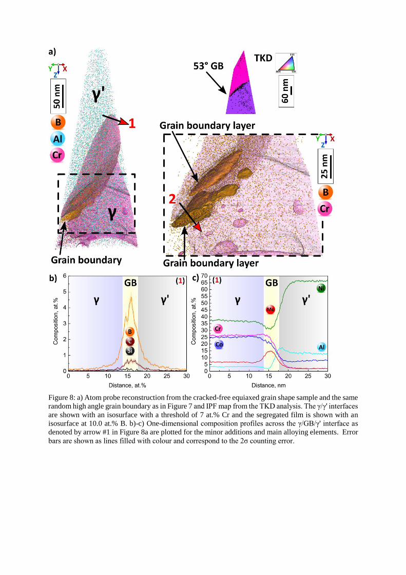
Figure 8: a) Atom probe reconstruction from the cracked-free equiaxed grain shape sample and the same
random high angle grain boundary as in Figure 7 and IPF map from the TKD analysis. The γ/γ' interfaces
are shown with an isosurface with a threshold of 7 at.% Cr and the segregated film is shown with an
isosurface at 10.0 at.% B. b)-c) One-dimensional composition profiles across the γ/GB/γ' interface as
denoted by arrow #1 in Figure 8a are plotted for the minor additions and main alloying elements. Error
bars are shown as lines filled with colour and correspond to the 2σ counting error.
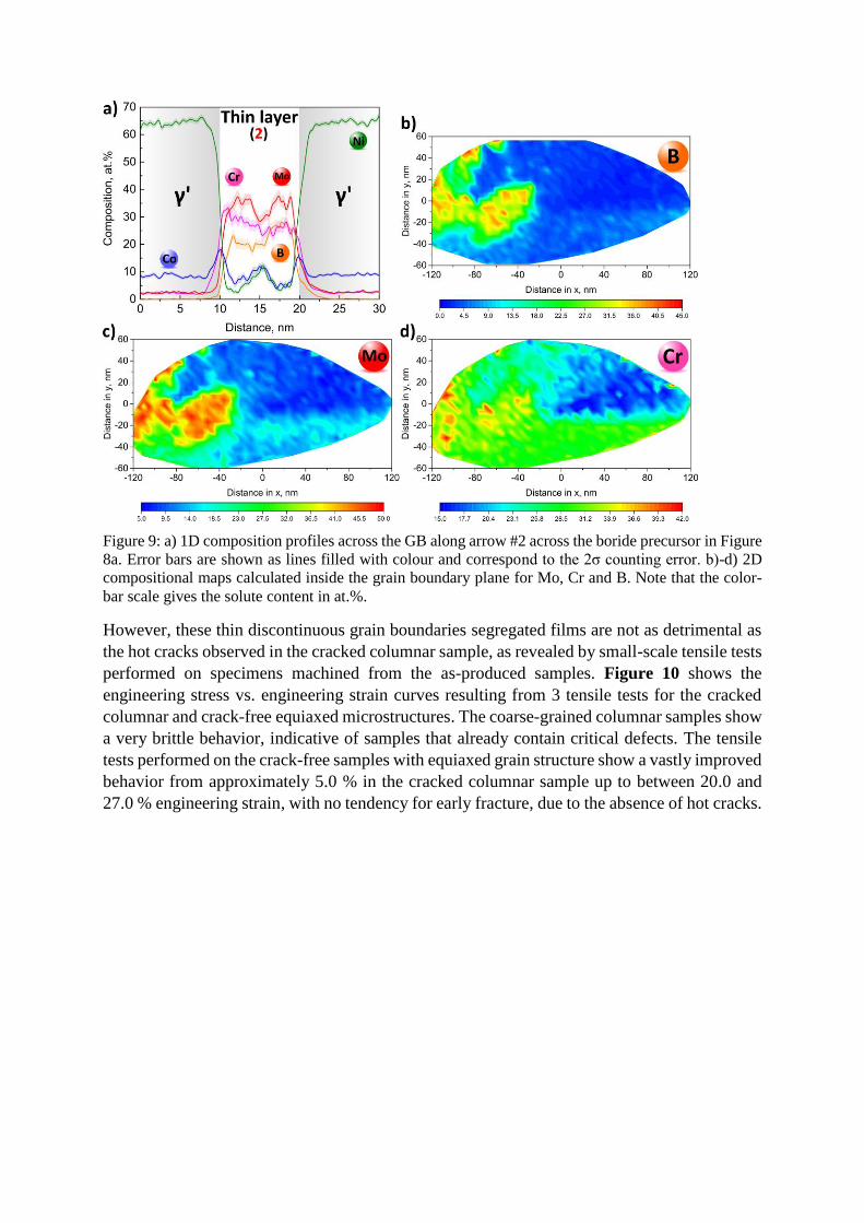
Figure 9: a) 1D composition profiles across the GB along arrow #2 across the boride precursor in Figure
8a. Error bars are shown as lines filled with colour and correspond to the 2σ counting error. b)-d) 2D
compositional maps calculated inside the grain boundary plane for Mo, Cr and B. Note that the color-
bar scale gives the solute content in at.%.
However, these thin discontinuous grain boundaries segregated films are not as detrimental as
the hot cracks observed in the cracked columnar sample, as revealed by small-scale tensile tests
performed on specimens machined from the as-produced samples. Figure 10 shows the
engineering stress vs. engineering strain curves resulting from 3 tensile tests for the cracked
columnar and crack-free equiaxed microstructures. The coarse-grained columnar samples show
a very brittle behavior, indicative of samples that already contain critical defects. The tensile
tests performed on the crack-free samples with equiaxed grain structure show a vastly improved
behavior from approximately 5.0 % in the cracked columnar sample up to between 20.0 and
27.0 % engineering strain, with no tendency for early fracture, due to the absence of hot cracks.
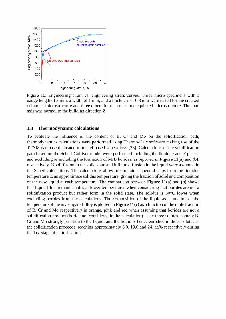
Figure 10: Engineering strain vs. engineering stress curves. Three micro-specimens with a
gauge length of 3 mm, a width of 1 mm, and a thickness of 0.8 mm were tested for the cracked
columnar microstructure and three others for the crack-free equiaxed microstructure. The load
axis was normal to the building direction Z.
3.3 Thermodynamic calculations
To evaluate the influence of the content of B, Cr and Mo on the solidification path,
thermodynamics calculations were performed using Thermo-Calc software making use of the
TTNI8 database dedicated to nickel-based superalloys [28]. Calculations of the solidification
path based on the Scheil-Gulliver model were performed including the liquid, and ' phases
and excluding or including the formation of M2B borides, as reported in Figure 11(a) and (b),
respectively. No diffusion in the solid state and infinite diffusion in the liquid were assumed in
the Scheil-calculations. The calculations allow to simulate sequential steps from the liquidus
temperature to an approximate solidus temperature, giving the fraction of solid and composition
of the new liquid at each temperature. The comparison between Figure 11(a) and (b) shows
that liquid films remain stables at lower temperatures when considering that borides are not a
solidification product but rather form in the solid state. The solidus is 60°C lower when
excluding borides from the calculations. The composition of the liquid as a function of the
temperature of the investigated alloy is plotted in Figure 11(c) as a function of the mole fraction
of B, Cr and Mo respectively in orange, pink and red when assuming that borides are not a
solidification product (boride not considered in the calculation). The three solutes, namely B,
Cr and Mo strongly partition to the liquid, and the liquid is hence enriched in those solutes as
the solidification proceeds, reaching approximately 6.0, 19.0 and 24. at.% respectively during
the last stage of solidification.
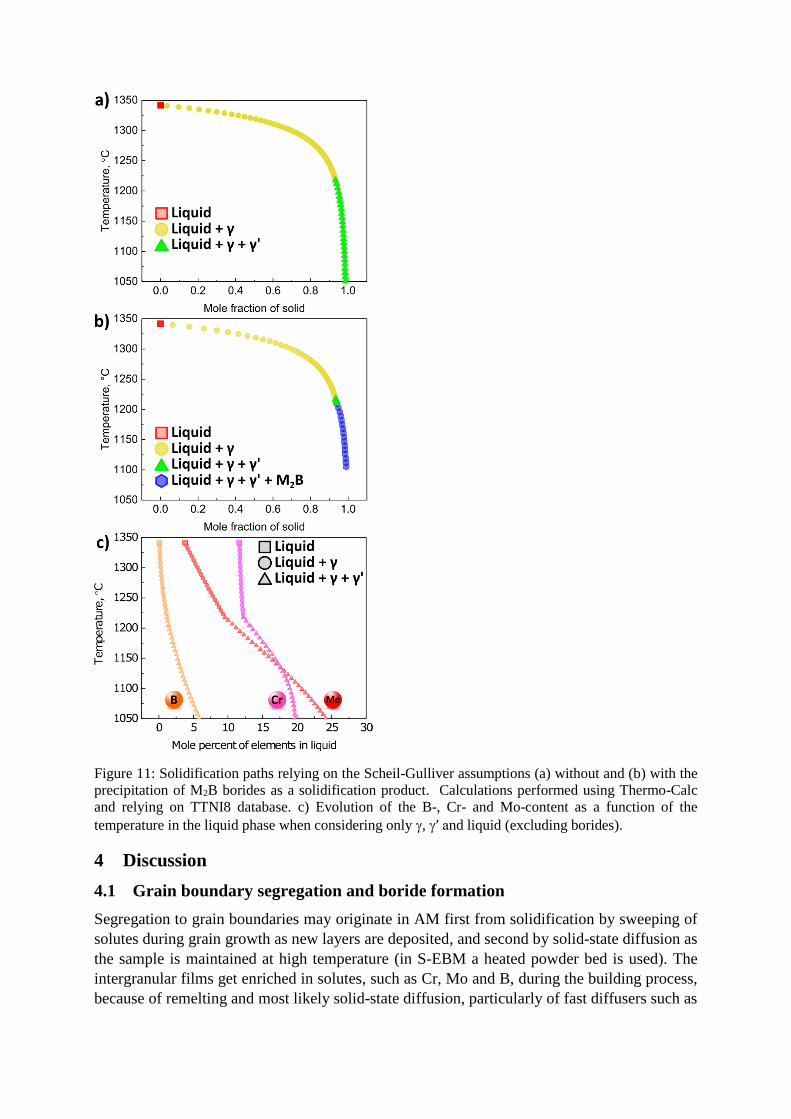
Figure 11: Solidification paths relying on the Scheil-Gulliver assumptions (a) without and (b) with the
precipitation of M2B borides as a solidification product. Calculations performed using Thermo-Calc
and relying on TTNI8 database. c) Evolution of the B-, Cr- and Mo-content as a function of the
temperature in the liquid phase when considering only , ′ and liquid (excluding borides).
4 Discussion
4.1 Grain boundary segregation and boride formation
Segregation to grain boundaries may originate in AM first from solidification by sweeping of
solutes during grain growth as new layers are deposited, and second by solid-state diffusion as
the sample is maintained at high temperature (in S-EBM a heated powder bed is used). The
intergranular films get enriched in solutes, such as Cr, Mo and B, during the building process,
because of remelting and most likely solid-state diffusion, particularly of fast diffusers such as

B [26]. HAGBs accommodate larger amounts of solutes than LAGBs [35], partly due to lower
their relatively higher interfacial energy [36].
Figure 4, Figure 7 and Figure 8 show clear segregation of B, Mo, and Cr to the grain
boundaries. Under non-equilibrium conditions, such as experienced during S-EBM,
thermodynamic calculations of the first solidification event predict a substantial enrichment of
B, Mo and Cr in the liquid as the temperature decreases, as reported in Figure 11(c). The
enrichment predicted by the Scheil-Gulliver calculations is however likely insufficient to form
borides during the first solidification event, which is supported by the absence of borides in the
last deposited layer. Upon several remelting events, as B gets more enriched and thus
concentrated, a critical composition of boride-formers is finally reached and borides can
nucleate. They can likely form in the liquid or heterogeneously in the solid state, and coarsen
quickly as HAGBs are fast diffusing paths.
The small off-stoichiometric borides observed in the sample with equiaxed grains are an
indication that the borides form and grow progressively during the build, and those observed
here, albeit small, resulted from multiple reheating/remelting events. These small borides can
thus be interpreted as early-stage variants of the larger borides observed in the coarse-grained
columnar sample. The composition profile shows an enrichment of Co up to 18.0 at.% at the
interface between' and the boride-precursor compared to 10.0 at.% within the ' precipitate
and 5.0-10.0 at.% within the off-stoichiometric borides. This indicates outward Co diffusion
from the boride towards the ' precipitate. Fully developed borides analyzed in the coarse-
grained columnar sample contain only approx. 2 at.% Co, while these precursors still contain
approximately 5.0 to 10.0 at.%. Also these findings support the assumption that we observed
here a transient state. In cases where borides do not deplete the film in B, Mo and Cr, the high
content in these boride-forming solutes in the last solidified liquid films lowers the alloy’s
solidus potentially significantly, as indicated by the results reported in Figure 11(a) and 11(c).
The growth of borides consumes solutes, which, as indicated by thermodynamic calculations,
increases the local solidus near the boride by locally decreasing the content of solutes such as
B and Mo, as proven in Figure 9. In such a case, isolated sections of solid binding between two
adjacent grains appear within the liquid film, as revealed in Figure 3(a). This finding illustrates
the direct influence of the local partition effects and hence of the local solute composition
content on the solidification, and hence on the cracking susceptibility.
4.2 Hot cracking caused by grain boundary-segregation induced liquation
Figure 1(f) gives strong indication that cracks are caused by interfacial liquation along some
of the grain boundaries and Figure 2 demonstrates that the cracks do not originate directly from
the first solidification event since no cracks propagate through the last melted layer.
Thermodynamic calculations demonstrate a progressive enrichment in critical solutes within
the liquid film during the last stage of the first solidification event. The characterization by APT
of the films observed along HAGBs confirms a significant enrichment in these same critical
solutes, namely Cr, Mo and B, which can be further accentuated by both successive remelting
and solid-state diffusion. This is particularly true for fast diffusing elements, such as B.
Regarding the cracking mechanism evolving during the building process, over the course of the
deposition of the subsequent layers, a segregated film at a HAGB can turn into a liquid film.
The drop in the solidus caused by the progressive enrichment in solute is referred to as
“segregation induced liquation” [37]. The difference in volume between the liquid and solid
phase associated with the solidification, i.e. the shrinkage effect, as well as thermal stresses
caused by rapid cooling provide the mechanical driving forces for the development of hot cracks
[38]. These local thermal stresses combined with segregation-driven grain boundary liquation
cause hot cracking [39,40]. The building history of the cracked columnar sample that leads to
cracking is summarised in the schematic in Figure 12. Ultimately, hot cracking requires a
condition setting where concentration in the liquid reaches a critical value, which appears close
to the critical composition to form borides, in combination with the solidification stresses.
B is usually added to superalloys to increase GB cohesion [41] and limit damage at GBs under
creep conditions. However, here it acts detrimental and promotes hot cracking as it depresses
the solidus temperature, hence stabilize liquid films to lower temperatures. The limited number
of grain boundaries in columnar samples will tend to have a more highly concentrated and
continuous films extending over several grains, which appears to be highly detrimental to the
structural integrity of the build. The typical criterion for non-weldability, namely the content of
(Ti+Al) [2], does not seem to apply here. In the alloy that we investigated, this criterion is
superseded by the content of B, Cr and Mo found at HAGBs. Ultimately, HAGBs crack because
(i) the films are continuous and extend over several mm and (ii) the local composition of the
segregated films allows the liquid to remain stable to relatively lower temperatures, hence
causing grain boundary liquation during the deposition of the subsequent layers. Our
observations imply that a bulk-criterion may not allow to appropriately depict near-atomic-scale
processes.

Figure 12: Schematic summary of the microstructural and compositional evolution during the build of
the sample with hot cracks.
It is also known that Zr promotes hot cracking in nickel-based superalloys produced by casting
[42–45] and AM processes [5]. Although Zr is added in the bulk composition of the investigated
alloy (0.02 – 0.025 at.%), APT revealed no segregation of Zr at the grain boundary. Our
observation on Zr is consistent with other studies performed by Cadel et al. [29] and
Lemarchand et al. [34]. By contrast, Zr was found to partition to the γ' phase for both columnar
cracked and equiax crack-free samples, as shown in Supplementary Figure 1. However, in a
different nickel-based superalloy, Zr was found to segregate at the grain boundary [5]. Besides,
significant interactions between Zr and B were recently reported during casting [44]. In order
to rationalize the interactions between the different alloying elements in such chemically
complex metallic systems, further detailed investigations are required which are outside the
scope of this present work.
4.3 Strategies for additive manufacturing of crack-free superalloys components
Better understanding and quantitative mapping of solute segregation to grain boundaries allows
us to derive strategies to avoid cracking in additively manufactured superalloy parts.
Modulating solute segregation at grain boundaries allows to better control liquation and better
distribute the thermal stresses associated to solidification and rapid cooling. This can be
achieved by controlling the total interfacial area. This means that, depending on the bulk
concentration of critical solutes, one has to adjust the overall interfacial area to gain control
over their segregation to HAGBs in order to avoid liquation.
Interestingly, our APT results show higher solute enrichment along HAGBs in the crack-free
sample with equiaxed grains compared to the ones in the cracked columnar sample. At first
sight, it could be considered as not consistent with our argument stating that increasing the
interfacial area should result in a less concentrated thin segregated films in critical solutes, i.e.
the ones reducing the solidus temperature. The distribution of solutes at larger interfacial are
would then allow to limit critical grain boundary segregation that can lead to liquation in
presence of thermal stresses. However, those results have to be considered in light of the
presence of coarse micron-sized borides that consume large quantities of critical solutes such
as B, Mo and Cr. In the cracked sample with columnar grains we have extracted APT specimens
in the immediate vicinity of coarse borides. We show how the precipitation of borides along
HAGB and the associated partitioning of grain boundary solutes into these particles can affect
locally the grain boundary segregation. Our results suggest that prior to boride formation,
HAGBs were likely decorated by a continuous and highly segregated film, which increases the
liquation susceptibility. However, this contradicts our observations at HAGBs in the sample
with equiaxed grains, where no borides and no cracks were observed, only discontinuous
segregated films. In the equiaxed sample, the grain boundary enrichment in B, Cr and Mo had
also slowed down as solutes are spread over a wider area and must diffuse over longer distances
to reach a high local composition. Conversely to the cracked columnar sample, the grain
boundary area in the equiaxed samples translates into discontinuous segregated films as
evidenced in Figure 6(b). In addition, the presence of more interfaces in the equiaxed version
helps to better accommodate solidification shrinkage and thermal stresses, hence the likelihood
of crack initiation is significantly reduced in comparison with a microstructure made of coarse
columnar grains.
It becomes apparent that a strategy for AM produced crack-free superalloys should have good
control of the total interfacial area of the produced component. This will prevent from reaching
the critical composition for the formation of detrimental continuous liquid films and undesirable
local thermal stresses over very few interfaces.
Based on this strategy aiming at controlling carefully the interfacial area, it would be possible
to produce a crack-free columnar sample, by once again taking advantage of the digital control
of the melting strategy offered by S-EBM, to achieve a critical grain width that leads to crack-
free samples. Figure 13 shows the evolution of grain width as a function of building height for
the cracked columnar and crack-free equiaxed sample. It can be seen that for a grain width of
approximately 20 μm, the equiaxed sample is crack free. Interestingly, the cracked columnar is
also free of cracks over the first roughly 10 millimetres of the build which corresponds to a
grain width lower than 100 microns. In other words, by producing a finer columnar
microstructure with grain width < 100 μm, one should get samples free of cracks.
We have produced a third sample which was built by using a relatively low power and slow
scan speed (linear energy of 0.3 J/mm²) while maintaining a line offset of 0.1 mm. The low
power maintains a relatively small melt pool that hinders grain coarsening and limits grain
selection. As a result, the grain width remains small, approximately 45 μm as shown in Figure
13 along the entire height of the build. An overview of this fine columnar microstructure shows
no hot cracks, as revealed in Figure 14.
A possible alternative route would consist in adjusting the composition to achieve lower level
of solutes along HAGBs that decrease the solidus for instance or to form a continuous layer of
e.g. borides to strengthen the grain boundaries [26,46].
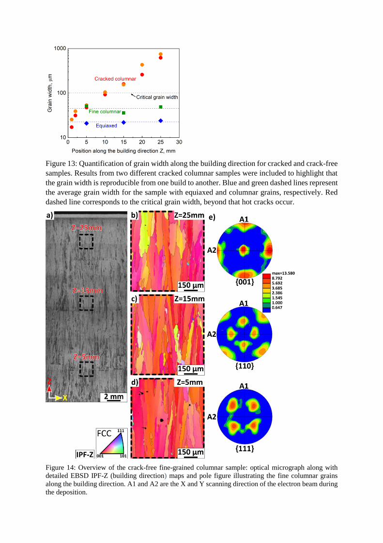
Figure 13: Quantification of grain width along the building direction for cracked and crack-free
samples. Results from two different cracked columnar samples were included to highlight that
the grain width is reproducible from one build to another. Blue and green dashed lines represent
the average grain width for the sample with equiaxed and columnar grains, respectively. Red
dashed line corresponds to the critical grain width, beyond that hot cracks occur.
Figure 14: Overview of the crack-free fine-grained columnar sample: optical micrograph along with
detailed EBSD IPF-Z (building direction) maps and pole figure illustrating the fine columnar grains
along the building direction. A1 and A2 are the X and Y scanning direction of the electron beam during
the deposition.
5. Conclusions
To conclude, we combined microstructural observations by optical and electron microscopy
with near-atomic scale compositional investigation of critical microstructural features by atom
probe tomography, and thermodynamic calculations to study additively manufactured builds
from a non-weldable nickel-based superalloy produced by S-EBM. Our approach allowed us to
provide fundamental insights into the dynamic interplay, at the nano-scale, of the local
composition in critical regions, such as HAGBs, that leads to segregation-induced liquation
cracking.
The new fundamental understanding of the root cause of cracking set us on the path to tune the
atomic-scale distribution of critical solutes, such as B, Cr and Mo, in particular along HAGBs.
This was made possible by the high level of control over the melting strategy offered by the S-
EBM process. Through modifications in the melting strategy, we adjusted the geometry of the
melt pool which turned the coarse-grained columnar microstructure sensitive to liquation
cracking into either small grained equiaxed (grain width approximately 20 μm) or fine columnar
microstructures (grain width approximately 50 μm). Increasing the interfacial area not only
prevents high concentration of boride-forming elements that cause liquation, and hence avoids
cracking but also helps to distribute thermal stresses over more interfaces.
Acknowledgements
This work was performed within the framework of the Center of Excellence of Multifunctional
Architectured Materials ‘‘CEMAM’’ n°AN-10-LABX-44-01 funded by the ‘‘Investments for
the Future Program’’. The authors are grateful to Poly-Shape for their contribution to funding
this work. We thank Uwe Tezins & Andreas Sturm for their support to the FIB & APT facilities
at MPIE. We are grateful for the financial support from the Max-Planck Gesellschaft via the
Laplace project for both equipment and personel (PK, AKdS). ZP acknowledges financial
support from the BIGMAX project. JH is grateful for funding by the DFG through the SFB
TR103. BG acknowledge financial support from the ERC-CoG-SHINE-771602.
Author contributions
P.K., B.G., J-J.B and G.M. designed the study. E.C. and G.M. 3D-printed the alloy. P.K., B.G.
and D.R. prepared the atom probe specimens, processed the data and interpreted the results.
Z.P. conducted the grain boundary analysis. J.H. and P.K. conducted the TKD analysis. A.K.S.
performed Thermo-Calc calculations, C.T. provided support on these. B.G., P.K. and G.M.
wrote the main draft of the paper. All authors contributed to the discussion of the results and
commented on the manuscript.
References
[1] S.S. Babu, N. Raghavan, J. Raplee, S.J. Foster, C. Frederick, M. Haines, R. Dinwiddie,
M.K. Kirka, A. Plotkowski, Y. Lee, R.R. Dehoff, Additive Manufacturing of Nickel
Superalloys: Opportunities for Innovation and Challenges Related to Qualification,
Metall. Mater. Trans. A. 49 (2018) 3764–3780. doi:10.1007/s11661-018-4702-4.
[2] M.M. Attallah, R. Jennings, X. Wang, L.N. Carter, Additive manufacturing of Ni-based
superalloys : The outstanding issues, (2016) 758–764. doi:10.1557/mrs.2016.211.
[3] R. Engeli, T. Etter, S. Hövel, K. Wegener, Processability of different IN738LC powder
batches by selective laser melting, J. Mater. Process. Technol. 229 (2016) 484–491.

doi:10.1016/J.JMATPROTEC.2015.09.046.
[4] M. Zhong, H. Sun, W. Liu, X. Zhu, J. He, Boundary liquation and interface cracking
characterization in laser deposition of Inconel 738 on directionally solidified Ni-based
superalloy, Scr. Mater. 53 (2005) 159–164. doi:10.1016/J.SCRIPTAMAT.2005.03.047.
[5] M. Cloots, P.J. Uggowitzer, K. Wegener, Investigations on the microstructure and crack
formation of IN738LC samples processed by selective laser melting using Gaussian and
doughnut profiles, Mater. Des. 89 (2016) 770–784.
[6] M. Ramsperger, R.F. Singer, C. Körner, Microstructure of the Nickel-Base Superalloy
CMSX-4 Fabricated by Selective Electron Beam Melting, Metall. Mater. Trans. A. 47
(2016) 1469–1480. doi:10.1007/s11661-015-3300-y.
[7] L.N. Carter, C. Martin, P.J. Withers, M.M. Attallah, The influence of the laser scan
strategy on grain structure and cracking behaviour in SLM powder-bed fabricated nickel
superalloy, J. Alloys Compd. 615 (2014) 338–347.
doi:10.1016/J.JALLCOM.2014.06.172.
[8] L.E. Murr, E. Martinez, X.M. Pan, S.M. Gaytan, J.A. Castro, C.A. Terrazas, F. Medina,
R.B. Wicker, D.H. Abbott, Microstructures of Rene 142 nickel-based superalloy
fabricated by electron beam melting, Acta Mater. 61 (2013) 4289–4296.
doi:10.1016/J.ACTAMAT.2013.04.002.
[9] Y.S. Lee, M.M. Kirka, S. Kim, N. Sridharan, A. Okello, R.R. Dehoff, S.S. Babu,
Asymmetric Cracking in Mar-M247 Alloy Builds During Electron Beam Powder Bed
Fusion Additive Manufacturing, Metall. Mater. Trans. A. 49 (2018) 5065–5079.
doi:10.1007/s11661-018-4788-8.
[10] H. Helmer, A. Bauereiß, R.F. Singer, C. Körner, Grain structure evolution in Inconel 718
during selective electron beam melting, Mater. Sci. Eng. A. 668 (2016) 180–187.
doi:10.1016/J.MSEA.2016.05.046.
[11] H.E. Helmer, C. Körner, R.F. Singer, Additive manufacturing of nickel-based superalloy
Inconel 718 by selective electron beam melting: Processing window and microstructure,
J. Mater. Res. 29 (2014) 1987–1996. doi:10.1557/jmr.2014.192.
[12] R.R. Dehoff, M.M. Kirka, W.J. Sames, H. Bilheux, A.S. Tremsin, L.E. Lowe, S.S. Babu,
Site specific control of crystallographic grain orientation through electron beam additive
manufacturing, Mater. Sci. Technol. 31 (2014) 931–938.
doi:10.1179/1743284714y.0000000734.
[13] R.R. Dehoff, M.M. Kirka, F.A. List, K.A. Unocic, W.J. Sames, Crystallographic texture
engineering through novel melt strategies via electron beam melting: Inconel 718, Mater.
Sci. Technol. 31 (2015) 939–944. doi:10.1179/1743284714Y.0000000697.
[14] J.A. Koepf, M.R. Gotterbarm, M. Markl, C. Körner, 3D multi-layer grain structure
simulation of powder bed fusion additive manufacturing, Acta Mater. 152 (2018) 119–
126. doi:10.1016/J.ACTAMAT.2018.04.030.
[15] J.A. Koepf, D. Soldner, M. Ramsperger, J. Mergheim, M. Markl, C. Körner, Numerical
microstructure prediction by a coupled finite element cellular automaton model for
selective electron beam melting, Comput. Mater. Sci. 162 (2019) 148–155.
doi:10.1016/J.COMMATSCI.2019.03.004.
[16] N. Raghavan, S. Simunovic, R. Dehoff, A. Plotkowski, J. Turner, M. Kirka, S.S. Babu,
Localized melt-scan strategy for site specific control of grain size and primary dendrite
arm spacing in electron beam additive manufacturing, Acta Mater. 140 (2017) 375–387.
doi:10.1016/j.actamat.2017.08.038.
[17] N. Raghavan, R. Dehoff, S. Pannala, S. Simunovic, M. Kirka, J. Turner, N. Carlson, S.S.
Babu, Numerical modeling of heat-transfer and the influence of process parameters on
tailoring the grain morphology of IN718 in electron beam additive manufacturing, Acta
Mater. 112 (2016) 303–314. doi:10.1016/j.actamat.2016.03.063.
[18] E. Chauvet, P. Kontis, E.A. Jägle, B. Gault, D. Raabe, C. Tassin, J.-J. Blandin, R.
Dendievel, B. Vayre, S. Abed, G. Martin, Hot cracking mechanism affecting a non-
weldable Ni-based superalloy produced by selective electron Beam Melting, Acta Mater.
142 (2018). doi:10.1016/j.actamat.2017.09.047.
[19] N. Wang, S. Mokadem, M. Rappaz, W. Kurz, Solidification cracking of superalloy
single- and bi-crystals, Acta Mater. 52 (2004) 3173–3182.
doi:10.1016/J.ACTAMAT.2004.03.047.
[20] M. Rappaz, J.-M. Drezet, M. Gremaud, A new hot-tearing criterion, Metall. Mater.
Trans. A. 30 (1999) 449–455. doi:10.1007/s11661-999-0334-z.
[21] C. Körner, M. Ramsperger, C. Meid, D. Bürger, P. Wollgramm, M. Bartsch, G. Eggeler,
Microstructure and Mechanical Properties of CMSX-4 Single Crystals Prepared by
Additive Manufacturing, Metall. Mater. Trans. A. 49 (2018) 3781–3792.
doi:10.1007/s11661-018-4762-5.
[22] E. Chauvet, C. Tassin, J.-J. Blandin, R. Dendievel, G. Martin, Producing Ni-base
superalloys single crystal by selective electron beam melting, Scr. Mater. 152 (2018) 15–
19. doi:10.1016/J.SCRIPTAMAT.2018.03.041.
[23] V. Juechter, T. Scharowsky, R.F. Singer, C. Körner, Processing window and evaporation
phenomena for Ti–6Al–4V produced by selective electron beam melting, Acta Mater. 76
(2014) 252–258.
[24] H.E. Helmer, A. Bauereiß, R.F. Singer, C. Körner, Grain structure evolution in Inconel
718 during selective electron beam melting, Mater. Sci. Eng. A. 668 (2016) 180–187.
doi:10.1016/j.msea.2016.05.046.
[25] K. Thompson, D. Lawrence, D.J. Larson, J.D. Olson, T.F. Kelly, B. Gorman, In situ site-
specific specimen preparation for atom probe tomography, Ultramicroscopy. 107 (2007)
131–139.
[26] P. Kontis, H.A.M. Yusof, S. Pedrazzini, M. Danaie, K.L. Moore, P.A.J. Bagot, M.P.
Moody, C.R.M. Grovenor, R.C. Reed, On the effect of boron on grain boundary
character in a new polycrystalline superalloy, Acta Mater. 103 (2016) 688–699.
[27] Z. Peng, Y. Lu, C. Hatzoglou, A. Kwiatkowski da Silva, F. Vurpillot, D. Ponge, D.
Raabe, B. Gault, An Automated Computational Approach for Complete In-Plane
Compositional Interface Analysis by Atom Probe Tomography, Microsc. Microanal. 15
(2019) 389–400. doi:10.1017/S1431927618016112.
[28] J.-O. Andersson, T. Helander, L. Höglund, P. Shi, B. Sundman, Thermo-Calc &
DICTRA, computational tools for materials science, Calphad. 26 (2002) 273–312.
doi:10.1016/S0364-5916(02)00037-8.
[29] E. Cadel, D. Lemarchand, S. Chambreland, D. Blavette, Atom probe tomography
investigation of the microstructure of superalloys N18, Acta Mater. 50 (2002) 957–966.
[30] P. Kontis, D.M. Collins, A.J. Wilkinson, R.C. Reed, D. Raabe, B. Gault, Microstructural
degradation of polycrystalline superalloys from oxidized carbides and implications on
crack initiation, Scr. Mater. 147 (2018) 59–63.
[31] P. Kontis, A. Kostka, D. Raabe, B. Gault, Influence of composition and precipitation
evolution on damage at grain boundaries in a crept polycrystalline Ni-based superalloy,
Acta Mater. 166 (2019) 158–167. doi:10.1016/j.actamat.2018.12.039.
[32] P.A.J. Bagot, O.B.W. Silk, J.O. Douglas, S. Pedrazzini, D.J. Crudden, T.L. Martin, M.C.
Hardy, M.P. Moody, R.C. Reed, An Atom Probe Tomography study of site preference
and partitioning in a nickel-based superalloy, Acta Mater. 125 (2017) 156–165.
[33] T. Alam, M. Chaturvedi, S.P. Ringer, J. Cairney, The early stages of ageing in the Ni-
based superalloy, inconel 718, in: Mater. Forum, 2008: pp. 1–5.
[34] D. Lemarchand, E. Cadel, S. Chambreland, D. Blavette, Investigation of grain-boundary
structure-segregation relationship in an N18 nickel-based superalloy, Philos. Mag. A. 82
(2002) 1651–1669.
[35] M. Herbig, D. Raabe, Y.J. Li, P. Choi, S. Zaefferer, S. Goto, Atomic-Scale
Quantification of Grain Boundary Segregation in Nanocrystalline Material, Phys. Rev.
Lett. 112 (2014) 126103. doi:10.1103/PhysRevLett.112.126103.
[36] S.-W. Chan, R.W. Balluffi, Study of energy vs misorientation for grain boundaries in
gold by crystallite rotation method—II. Tilt boundaries and mixed boundaries, Acta
Metall. 34 (1986) 2191–2199. doi:10.1016/0001-6160(86)90164-1.
[37] S. Kou, Welding Metallurgy [Hardcover], 2nd Editio, Wiley: New York, 2003, New
York, 2002.
[38] S.S. Babu, S.A. David, J.W. Park, J.M. Vitek, Joining of nickel base superalloy single
crystals, Sci. Technol. Weld. Join. 9 (2004) 1–12. doi:10.1179/136217104225017080.
[39] O.A. Ojo, N.L. Richards, M.C. Chaturvedi, Contribution of constitutional liquation of
gamma prime precipitate to weld HAZ cracking of cast Inconel 738 superalloy, Scr.
Mater. 50 (2004) 641–646. doi:10.1016/j.scriptamat.2003.11.025.
[40] O.A. Ojo, Y.L. Wang, M.C. Chaturvedi, Heat affected zone liquation cracking in
electron beam welded third generation nickel base superalloys, Mater. Sci. Eng. A. 476
(2008) 217–223. doi:10.1016/j.msea.2007.04.091.
[41] D. Tytko, P.-P. Choi, J. Klöwer, A. Kostka, G. Inden, D. Raabe, Microstructural
evolution of a Ni-based superalloy (617B) at 700 °C studied by electron microscopy and
atom probe tomography, Acta Mater. 60 (2012) 1731–1740.
[42] D. Heydari, A.S. Fard, A. Bakhshi, J.M. Drezet, Hot tearing in polycrystalline Ni-based
IN738LC superalloy: Influence of Zr content, J. Mater. Process. Technol. 214 (2014)
681–687.
[43] Y.Z. Zhou, A. Volek, Effect of grain boundary fraction on castability of a directionally
solidified nickel alloy, Scr. Mater. 54 (2006) 2169–2174.
[44] J. Grodzki, N. Hartmann, R. Rettig, E. Affeldt, R.F. Singer, Effect of B, Zr, and C on
Hot Tearing of a Directionally Solidified Nickel-Based Superalloy, Metall. Mater. Trans.
A. 47 (2016) 2914–2926.
[45] J. Zhang, R.F. Singer, Effect of Zr and B on castability of Ni-based superalloy IN792,
Metall. Mater. Trans. A. 35 (2004) 1337–1342.
[46] M. Kolb, L.P. Freund, F. Fischer, I. Povstugar, S.K. Makineni, B. Gault, D. Raabe, J.
Müller, E. Spiecker, S. Neumeier, M. Göken, On the grain boundary strengthening effect
of boron in γ/γ′ Cobalt-base superalloys, Acta Mater. 145 (2018).
doi:10.1016/j.actamat.2017.12.020.
Supplementary Figure
Supplementary Figure 1: a) One-dimensional composition profiles across the γ'/GB/γ interface as
denoted by arrow #1 in Figure 4a from the cracked columnar sample are plotted for Zr and Hf. b) One-
dimensional composition profiles across the γ/GB/γ' interface as denoted by arrow #1 in Figure 8a from
the crack-free equiaxed sample are plotted for Zr and Hf. Error bars are shown as lines filled with colour
and correspond to the 2σ counting error.