
620/640/642 - FAAC · Le symbole met en évidence les remarques pour la sécurité des personnes et...
14
620/640/642
Transcript of 620/640/642 - FAAC · Le symbole met en évidence les remarques pour la sécurité des personnes et...

620/640/642

Leggere completamente questo manuale di istruzioni prima di iniziare l’installazione del prodotto.
Il simbolo evidenzia le note importanti per la sicurezza delle persone e l’integrità dell’automazione.
Il simbolo richiama l’attenzione sulle note riguardanti le caratteristiche od il funzionamento del prodotto.
Read this instruction manual to the letter before you begin to install the product.
Symbol highlights notes that are important for people’s safety and for the good condition of the automated system.
Symbol draws your attention to the notes about the product’s characteristics or operation.
Lire ce manuel d’instructions dans son entier avant de commencer l’installation du produit.
Le symbole met en évidence les remarques pour la sécurité des personnes et le parfait état de l’automatisme.
Le symbole attire l’attention sur les remarques concernant les caractéristiques ou le fonctionnement du produit.
Vor der Installation des Produkts sind die Anweisungen vollständig zu lesen.
Mit dem Symbol sind wichtige Anmerkungen für die Sicherheit der Personen und den störungsfreien Betrieb der Auto-
mation gekennzeichnet.
Mit dem Symbol wird auf Anmerkungen zu den Eigenschaften oder dem Betrieb des Produkts verwiesen.
Lean completamente este manual de instrucciones antes de empezar la instalación del producto.
El símbolo identifica notas importantes para la seguridad de las personas y para la integridad de la automación.
El símbolo llama la atención sobre las notas relativas a las características o al funcionamiento del producto.
Lees deze instructiehandleiding helemaal door alvorens het product te installeren.
Het symbool is een aanduiding van opmerkingen die belangrijk zijn voor de veiligheid van personen en voor een goede
automatische werking.
Het symbool vestigt de aandacht op opmerkingen over de eigenschappen of de werking van het product.

�
EN
GLIS
H
CE DECLARATION OF CONFORMITY FOR MACHINES ................................................................................................. 2
WARNINGS FOR THE INSTALLER ................................................................................................................................. 2
1. DESCRIPTION AND TECHNICAL SPECIFICATIONS ................................................................................................... 3
1.1 MAXIMUM USE CURVE ............................................................................................................................................. 4
2 ELECTRIC PREPARATIONS (standard system) .......................................................................................................... 4
3 DIMENSIONS ......................................................................................................................................................... 4
3.1 BARRIER 620 .................................................................................................................................................. 4
3.2 BARRIER 640 - 642 ......................................................................................................................................... 4
4 INSTALLING THE AUTOMATED SYSTEM .................................................................................................................... 4
4.1 PRELIMINARY CHECKS ............................................................................................................................................. 4
4.2 MASONRY FOR FOUNDATION PLINTH ....................................................................................................................... 4
4.3 MECHANICAL INSTALLATION ................................................................................................................................... 5
4.3.1 BARRIER 620 ................................................................................................................................................... 5
4.3.2 BARRIER 640 - 642 .......................................................................................................................................... 6
4.4 ADJUSTING THE BALANCING SPRING. ...................................................................................................................... 6
5 START-UP ................................................................................................................................................................. 6
5.1 CONNECTION TO CONTROL BOARD ....................................................................................................................... 6
5.2 ADJUSTING THE TRANSMITTED TORQUE .................................................................................................................... 6
5.3 ADJUSTING THE TRAVEL LIMIT SLOW DOWN ............................................................................................................. 6
5.4 AUTOMATED SYSTEM TEST ........................................................................................................................................ 7
6 MANUAL MODE OPERATION .................................................................................................................................. 7
7 RESTORING NORMAL OPERATION MODE ................................................................................................................ 7
8 MAINTENANCE ...................................................................................................................................................... 7
8.1 TOPPING UP OIL ...................................................................................................................................................... 7
8.2 BLEEDING OPERATION ............................................................................................................................................. 7
9 REPAIRS ................................................................................................................................................................. 8
10 CHANGING THE RH (LH) VERSION OF THE BARRIER INTO THE LH (RH) VERSION ...................................................... 8
11 AVAILABLE ACCESSORIES .................................................................................................................................... 8
12 DETAILED TECHNICAL SPECIFICATIONS ................................................................................................................. 10
INDEX

�
EN
GLIS
H
CE DECLARATION OF CONFORMITY FOR MACHINES(DIRECTIVE 98/37/EC)
Manufacturer: FAAC S.p.A.
Address: Via Benini, � - 40069 Zola Predosa BOLOGNA - ITALY
Declaresthat: Barrier mod. 6�0, mod. 640, mod. 64�,
• is built to be integrated into a machine or to be assembled with other machinery to create a machine under the provisions of Directive 98/37/EEC and subsequent amendments 91/368 EEC, 93/44 EEC and 93/68 EEC;
• conforms to the essential safety requirements of the other following EEC directives:
73/23/EEC and subsequent amendment 93/68/EEC. 89/336/EEC and subsequent amendment 92/31/EEC and 93/68/EEC
Furthermore, the manufacturer declares that the machinery must not be put into service until the machine into which it will be integrated or of which it will become a component has been identified and its conformity to the conditions of Directive 89/392/EEC and subsequent modifications assimilated in Italian National legislation under Presidential Decree No. 459 of 24 July 1996 has been declared.
.
Bologna, 0� June �007 The Managing Director A. Bassi
1) ATTENTION! To ensure the safety of people, it is important that you read all the following instructions. Incorrect installation or incorrect use of the product could cause serious harm to people.
2) Carefully read the instructions before beginning to install the product.
3) Do not leave packing materials (plastic, polystyrene, etc.) within reach of children as such materials are potential sources of danger.
4) Store these instructions for future reference.
5) This product was designed and built strictly for the use indicated in this documentation. Any other use, not expressly indicated here, could compromise the good condition/operation of the product and/or be a source of danger.
6) FAAC declines all liability caused by improper use or use other than that for which the automated system was intended.
7) Do not install the equipment in an explosive atmosphere: the presence of inflammable gas or fumes is a serious danger to safety.
8) The mechanical parts must conform to the provisions of Standards EN 12604 and EN 12605.
For non-EU countries, to obtain an adequate level of safety, the Standards mentioned above must be observed, in addition to national legal regulations.
9) FAAC is not responsible for failure to observe Good Technique in the construction of the closing elements to be motorised, or for any deformation that may occur during use.
10) The installation must conform to Standards EN 12453 and EN 12445.
For non-EU countries, to obtain an adequate level of safety, the Standards mentioned above must be observed, in addition to national legal regulations.
11) Before attempting any job on the system, cut out electrical power.
12) The mains power supply of the automated system must be fitted with an all-pole switch with contact opening distance of 3mm or greater. Use of a 6A thermal breaker with all-pole circuit break is recommended.
13) Make sure that a differential switch with threshold of 0.03 A is fitted upstream of the system.
14) Make sure that the earthing system is perfectly constructed, and connect metal parts of the means of the closure to it.
15) The automated system is supplied with an intrinsic anti-crushing safety device consisting of a torque control. Nevertheless, its tripping threshold must be checked as specified in the Standards indicated at point 10.
16) The safety devices (EN 12978 standard) protect any danger areas against mechanical movement Risks, such as crushing, dragging, and shearing.
17) Use of at least one indicator-light (e.g. FAACLIGHT) is recommended for every system, as well as a warning sign adequately secured to the frame structure, in addition to the devices mentioned at point “16”.
18) FAAC declines all liability as concerns safety and efficient operation of the automated system, if system components not produced by FAAC are used.
19) For maintenance, strictly use original parts by FAAC.
20) Do not in any way modify the components of the automated system.
21) The installer shall supply all information concerning manual operation of the system in case of an emergency, and shall hand over to the user the warnings handbook supplied with the product.
22) Do not allow children or adults to stay near the product while it is operating.
23) Keep radiocontrols or other pulse generators away from children, to prevent the automated system from being activated involuntarily.
24) Transit is permitted only when the automated system is idle.
25) The user must not attempt any kind of repair or direct action whatever and contact qualified personnel only.
26) Maintenance: check at least every 6 months the efficiency of the system, particularly the efficiency of the safety devices (including, where foreseen, the operator thrust force) and of the release devices.
27) Anything not expressly specified in these instructions is not permitted.
WARNINGS FOR THE INSTALLER
GENERAL SAFETY OBLIGATIONS
�
EN
GLIS
H
AUTOMATEDSYSTEM620-640-642
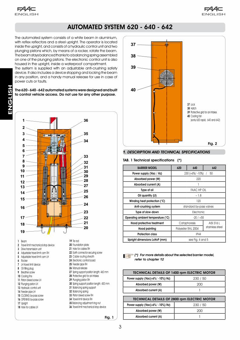
The automated system consists of a white beam in aluminium, with reflex reflectors and a steel upright. The operator is located inside the upright, and consists of a hydraulic control unit and two plunging pistons which, by means of a rocker, rotate the beam. The beam stays balanced thanks to a balancing spring assembled on one of the plunging pistons. The electronic control unit is also housed in the upright, inside a waterproof compartment.The system is supplied with an adjustable anti-crushing safety device. It also includes a device stopping and locking the beam in any position, and a handy manual release for use in case of power cuts or faults.
The620-640-642automatedsystemsweredesignedandbuilttocontrolvehicleaccess.Donotuseforanyotherpurpose.
Fig.1
1 Beam2 Travel limit mechanical stop device3 Drive transmission unit4 Adjustable travel limit cam RH5 Adjustable travel limit cam LH6 Rocker7 LH travel limit device 8 Oil filling plug9 Breather screw10 Cooling fins11 Piston bleed screw LH12 Plunging piston LH13 Hydraulic control unit14 Feeder pipe LH15 CLOSING by-pass screw16 OPENING by-pass screw17 Upright 18 Hole for cables LH
19 Tie rod20 Foundation plate21 Hole for cables RH22 Earth connector securing screw23 Cable routing sheath24 Electronic control board25 Feeder pipe RH26 Manual release27 Spring support position length: 460 mm28 Protective grid for air intakes29 Plunging piston RH30 Spring support position length: 400 mm 31 Balancing spring support32 Balancing spring33 Piston bleed screw RH34 Travel limit device RH35Balancing adjustment ring-nut36 Travel limit mechanical stop device
Fig.2
37 Lock38 Hatch 39 Protective grid for air intakes40 Cooling fan (sonly 6�0 rapid, 640 and 64�)
1. DESCRIPTION AND TECHNICAL SPECIFICATIONS
TAB.1Technicalspecifications(*)
BARRIER MODEL 620 640 642
Power supply (Vac / Hz) 230 {+6%/ -10%} / 50
Absorbed power (W) 220
Absorbed current (A) 1
Type of oil FAAC HP OIL
Oil quantity (Lt) ~ 1.8
Winding heat protection (°C) 120
Anti-crushing system standard by-pass valves
Type of slow-down Electronic
Operating ambient temperature (°C) -20 / +55
Hood protective treatment Cataphoresis AISI 316 L stainless steel Hood painting Polyester RAL 2004
Protection class IP44
Upright dimensions LxHxP (mm) see Fig. 4 and 5
(*) For more details about the selected barrier model, refer to chapter 12
TECHNICAL DETAILS OF 1400 rpm ELECTRIC MOTOR
Power supply (Vac{+6%/ -10%}/Hz) 230 / 50
Absorbed power (W) 200
Absorbed current (A) 1
TECHNICAL DETAILS OF 2800 rpm ELECTRIC MOTOR
Power supply (Vac{+6%/ -10%}/Hz) 230 / 50
Absorbed power (W) 200
Absorbed current (A) 1

4
L
380
230
50
1080
390
850
50
100
200
25
165
Ø 85
144
1080
LLP=L-144
25
105,
3
90
Ø 85
EN
GLIS
H
1.1 MAXIMUM USE CURVE
The curve makes it possible to establish maximum work time (T) according to use frequency (F).E.g.: Operators 6�0 rapid, 640, 64� R/40 and 64�/70 can operate non-stop at �00% use frequency as they are provided with a cooling fan. Models 6�0 standard and 64� std/40 can operate non-stop at 70% use frequency.To ensure efficient operation, operate in the work range under the curve.
Use frequency graph
Important: The curve is obtained at a temperature of �4 °C. Exposure to the direct sun rays can reduce use frequency down to �0%
Calculation of use frequency
The percentage of effective work time (opening + closing) compared to total time of cycle (opening + closing + pause times).Calculation formula:
Ta + Tc%F = X �00 Ta + Tc + Tp + Ti
where: Ta = opening timeTc = closing timeTp = pause timeTi = interval time between one complete cycle and another
2 ELECTRIC PREPARATIONS (standard system)
Fig.3
Barriers mod. 6�0 / 640 / 64�b Photocellsc Key push-button d Flashing light
Notes:�) To lay cables, use adequate rigid and/or flexible tubes.�) Always separate connection cables of low voltage accessories from those operating at ��0v~. To prevent any
interference whatever, use separate sheaths.
3 BARRIER DIMENSIONS
Fig.4Dimensions are in mm.
Fig.5Dimensions are in mm.
4 INSTALLING THE AUTOMATED SYSTEM
4.1 PRELIMINARY CHECKS
To ensure safety and an efficiently operating automated system, make sure the following conditions are observed:
• When moving, the beam must not, on any account, meet any obstacles or overhead power cables.
• The soil must permit sufficient stability for the foundation plinth.
• There must be no pipes or electrical cables in the plinth excavation area.
• if the barrier body is exposed to passing vehicles, install, if possible, adequate means of protection against accidental impact.
• Check if an efficient earth socket is available for connecting the upright.
3.1 BARRIER 620
3.2 BARRIERS 640 - 642
e Radio receiverf Magnetic loops
4.2 MASONRY FOR FOUNDATION PLINTH
WALLTHEFOUNDATIONPLATETOALLOWEASYACCESS TOTHEBARRIERHATCH.
�
A
600 mm400 mm
500
mm
5 m
m
= =
==
B
A
D
C
B A B
CD
EN
GLIS
H
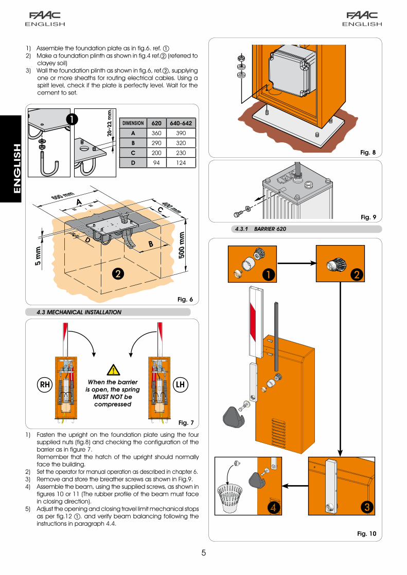
�) Fasten the upright on the foundation plate using the four supplied nuts (fig.8) and checking the configuration of the barrier as in figure 7.
Remember that the hatch of the upright should normally face the building.
�) Set the operator for manual operation as described in chapter 6.�) Remove and store the breather screws as shown in Fig.9.4) Assemble the beam, using the supplied screws, as shown in
figures �0 or �� (The rubber profile of the beam must face in closing direction).
�) Adjust the opening and closing travel limit mechanical stops as per fig.�� . and verify beam balancing following the instructions in paragraph 4.4.
�) Assemble the foundation plate as in fig.6. ref. �) Make a foundation plinth as shown in fig.4 ref.b (referred to
clayey soil)�) Wall the foundation plinth as shown in fig.6, ref.b, supplying
one or more sheaths for routing electrical cables. Using a spirit level, check if the plate is perfectly level. Wait for the cement to set.
Fig.6
Fig.7
4.3 MECHANICAL INSTALLATION
Fig.9
Fig.8
Fig.10
DIMENSION 620 640-642
A 360 390
B 290 320
C 200 230
D 94 124
When the barrier is open, the spring
MUST NOT be compressed
RH LH
4.3.1 BARRIER 620
6
EN
GLIS
H
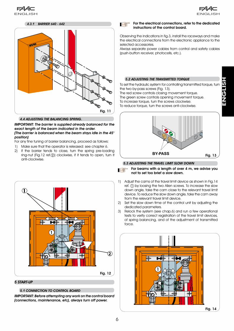
4.4 ADJUSTING THE BALANCING SPRING.
IMPORTANT: The barrier is supplied already balanced for the exact length of the beam indicated in the order. (The barrier is balanced when the beam stays idle in the 45° position)For any fine tuning of barrier balancing, proceed as follows:�) Make sure that the operator is released: see chapter 6.�) If the barrier tends to close, turn the spring pre-loading
ring-nut (Fig.�� ref.b) clockwise, if it tends to open, turn it anti-clockwise.
Fig.12
5 START-UP
5.1 CONNECTION TO CONTROL BOARD
IMPORTANT: Before attempting any work on the control board (connections, maintenance, etc), always turn off power.
5.2 ADJUSTING THE TRANSMITTED TORQUE
To set the hydraulic system for controlling transmitted torque, turn the two by-pass screws (Fig. ��). The red screw controls closing movement torque.The green screw controls opening movement torque.To increase torque, turn the screws clockwise.To reduce torque, turn the screws anti-clockwise.
5.3 ADJUSTING THE TRAVEL LIMIT SLOW DOWN
Forbeamswithalengthofover4m,weadviseyounottosettoobriefaslowdown.
�) Adjust the cams of the travel limit device as shown in Fig.�4 ref. by loosing the two Allen screws. To increase the slow down angle, take the cam close to the relevant travel limit device. To reduce the slow down angle, take the cam away from the relevant travel limit device.
�) Set the slow down time of the control unit by adjusting the dedicated parameters.
�) Relock the system (see chap.6) and run a few operational tests to verify correct registration of the travel limit devices, of spring balancing, and of the adjustment of transmitted force.
Fortheelectricalconnections,refertothededicatedinstructionsofthecontrolboard.
Observing the indications in fig.�, install the raceways and make the electrical connections from the electronic appliance to the selected accessories.Always separate power cables from control and safety cables (push-button receiver, photocells, etc.).
Fig.13
Fig.14
Fig.11
4.3.1 BARRIER 640 - 642
7
EN
GLIS
H
8 MAINTENANCE
Whenever doing 6-monthly maintenance, always check correct settings of the by-pass screws, system balancing, and efficiency of safety devices.
8.1 TOPPING UP OIL
Periodically check the quantity of oil inside the tank.An annual check is sufficient for low to medium use frequency; for heavier duty, check every 6 months.The level must not drop below the notch of the control stick (Fig.�8 ref. ) .To top-up, unscrew the filling plug (fig.�8) and pour in oil up to correct level.Use FAAC HP OIL and no other.
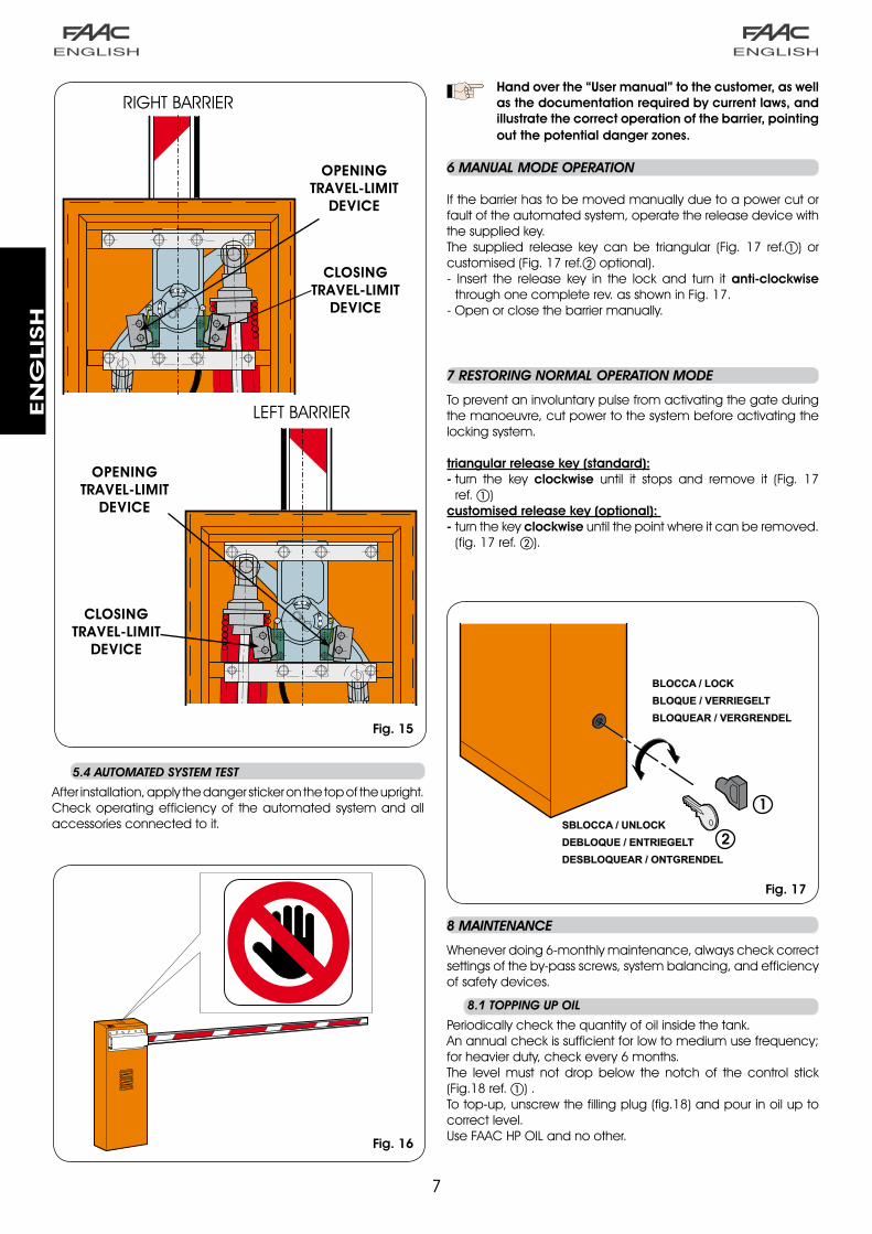
5.4 AUTOMATED SYSTEM TEST
After installation, apply the danger sticker on the top of the upright. Check operating efficiency of the automated system and all accessories connected to it.
Handoverthe“Usermanual”tothecustomer,aswellasthedocumentationrequiredbycurrentlaws,andillustratethecorrectoperationofthebarrier,pointingoutthepotentialdangerzones.
6 MANUAL MODE OPERATION
If the barrier has to be moved manually due to a power cut or fault of the automated system, operate the release device with the supplied key.The supplied release key can be triangular (Fig. �7 ref.) or customised (Fig. �7 ref.b optional).- Insert the release key in the lock and turn it anti-clockwise
through one complete rev. as shown in Fig. �7.- Open or close the barrier manually.
7 RESTORING NORMAL OPERATION MODE
To prevent an involuntary pulse from activating the gate during the manoeuvre, cut power to the system before activating the locking system.
triangularreleasekey(standard):-turn the key clockwise until it stops and remove it (Fig. �7
ref. ) customisedreleasekey(optional):-turn the keyclockwise until the point where it can be removed.
(fig. �7 ref. b).
CLOSING TRAVEL-LIMIT
DEVICE
CLOSING TRAVEL-LIMIT
DEVICE
OPENING TRAVEL-LIMIT
DEVICE
OPENING TRAVEL-LIMIT
DEVICE
Fig.15
Fig.16
Fig.17
RIGHT BARRIER
LEFT BARRIER

8
1
2
3 6
5
4
1
2
36
5
4
EN
GLIS
H
9 REPAIRS
For any repairs, contact FAAC’s authorised Repair Centres.
Fig.19
WHEN THE BARRIER IS OPEN, THE SPRING MUST NOT BE
COMPRESSED
10 CHANGING THE RH (LH) VERSION OF THE BARRIER INTO THE LH (RH) VERSION
Procedure for converting an RH (LH) version barrier into an LH (RH) version:
Release the barrier as shown in Chap.6.Position the beam in opening position and remove it from the pocket as shown in Fig. 10 or FIg.11.Re-lock the barrier as shown in Chap.7.Screw the bleed screw on the control unit (FIg.9).Fully loosen the spring adjustment ring-nut (Fig.19 ref.d). Detach the feed pipes (Fig.19 ref.c and f) from the two pistons and plug the unions.Remove the two pistons (Fig. 19 ref. b and e) from the upper and lower fittings and reverse their position, taking the rocker (Fig.18 ref. ). against the opening travel limit mechanical stop. Remove the pinion pocket and re-install it to set the barrier at opening as in figure 19.Fit the feed pipes as shown in Fig. 19, according to the configuration of the barrier (RH or LH).Reverse the travel limit connectors on the control unit.Remove the bleed screw (Fig.9) and carry out the air bleed operations as indicated in paragraph 8.2.Check the balance of the spring as indicated in paragraph 4.4.
1.2.
3.4.5.
6.
7.
8.
9.
10.11.
12.
8.2 BLEEDING OPERATION
If beam movement is incorrect, air must be bled from the hydraulic system. Procedure:�) Make sure that the bleed screw was eliminated (Fig.9)�) Activate the beam electrically: - during opening, slightly loosen and re-screw the bleed
screw of the piston with the balancing spring (Fig.� ref. ��) - during closure, slightly loosen and re-screw the bleed screw
of the piston without the balancing spring (Fig.� ref.��).�) If necessary, repeat the operation several times, until you
obtain correct beam movement.
Fig.18
LHRH
9
71.5
84
360
390
90
90
L
A = L-240620
A = L-450
L
640 - 642
EN
GLIS
H
NB.: Dimensions are in mm.
Fig.25
Fig.24
Fig.22
Fig.23
Fig.21
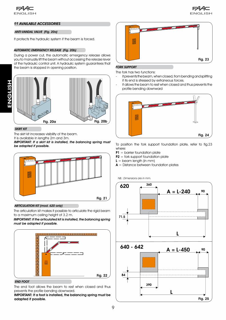
To position the fork support foundation plate, refer to fig.�� where:P1 = barrier foundation plateP2 = fork support foundation plateL= beam length (in mm)A= Distance between foundation plates
SKIRT KIT
The skirt kit increases visibility of the beam.It is available in lengths �m and �m.IMPORTANT: If a skirt kit is installed, the balancing spring must be adapted if possible.
ARTICULATION KIT (mod. 620 only)
The articulation kit makes it possible to articulate the rigid beam to a maximum ceiling height of �.� m.IMPORTANT: If the articulated kit is installed, the balancing spring must be adapted if possible.
END FOOT
The end foot allows the beam to rest when closed and thus prevents the profile bending downward.IMPORTANT:Ifafootisinstalled,thebalancingspringmustbeadaptedifpossible.
FORK SUPPORT
The fork has two functions:- it prevents the beam, when closed, from bending and splitting
if its end is stressed by extraneous forces.- it allows the beam to rest when closed and thus prevents the
profile bending downward
11 AVAILABLE ACCESSORIES
ANTI-VANDAL VALVE (Fig. 20a)
It protects the hydraulic system if the beam is forced.
AUTOMATIC EMERGENCY RELEASE (Fig. 20b)
During a power cut, the automatic emergency release allows you to manually lift the beam without accessing the release lever of the hydraulic control unit. A hydraulic system guarantees that the beam is stopped in opening position.
Fig.20bFig.20a
�0
EN
GLIS
H
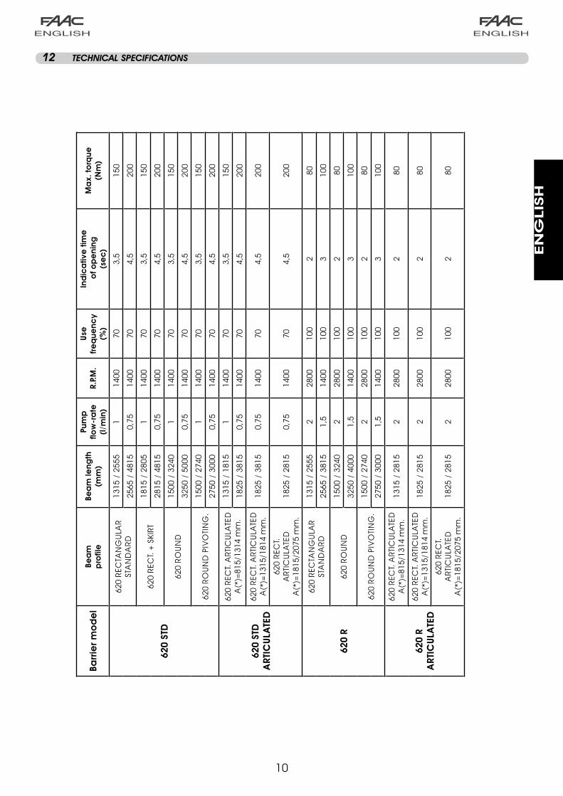
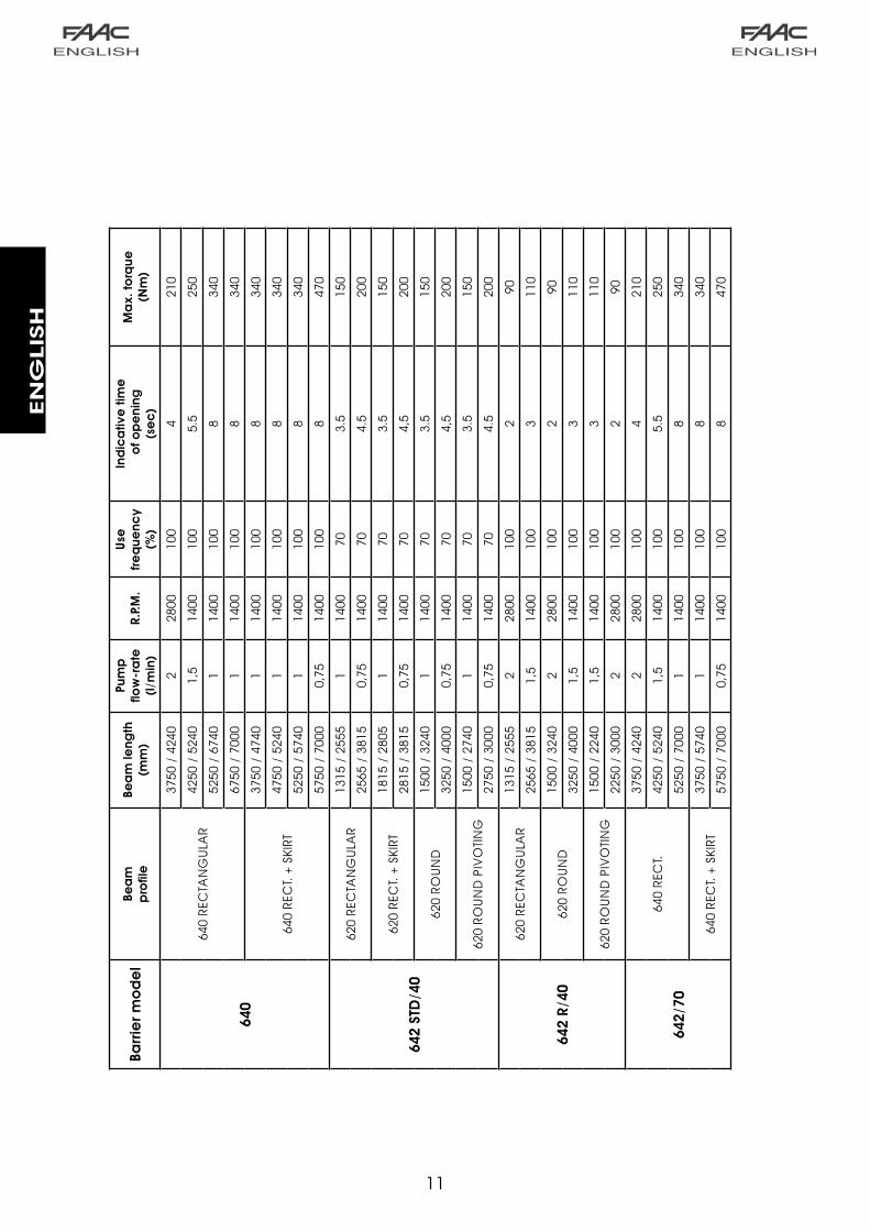
12 TECHNICAL SPECIFICATIONS
Barr
ier m
od
el
Bea
m
pro
file
Bea
m le
ngth
(m
m)
Pum
p
flow
-ra
te
(l/m
in)
R.P.
M.
Use
fre
que
ncy
(%
)
Ind
ica
tive
tim
e o
f op
eni
ng
(se
c)
Ma
x. to
rque
(N
m)
620
STD
620
REC
TAN
GU
LAR
ST
AN
DA
RD
1315
/ 2
555
114
0070
3,5
150
2565
/ 4
815
0,75
1400
704,
520
0
620
REC
T. +
SKI
RT18
15 /
280
51
1400
703,
515
0
2815
/ 4
815
0,75
1400
704,
520
0
620
RO
UN
D15
00 /
324
01
1400
703,
515
0
3250
/ 5
000
0,75
1400
704,
520
0
620
RO
UN
D P
IVO
TIN
G.
1500
/ 2
740
114
0070
3,5
150
2750
/ 3
000
0,75
1400
704,
520
0
620
STD
A
RTIC
ULA
TED
620
REC
T. A
RTIC
ULA
TED
A
(*)=
815/
1314
mm
.13
15 /
181
51
1400
703,
515
0
1825
/ 3
815
0,75
1400
704,
520
0
620
REC
T. A
RTIC
ULA
TED
A
(*)=
1315
/181
4 m
m.
1825
/ 3
815
0,75
1400
704,
520
0
620
REC
T.
ART
ICU
LATE
D
A(*
)=18
15/2
075
mm
.18
25 /
281
50,
7514
0070
4,5
200
620
R
620
REC
TAN
GU
LAR
ST
AN
DA
RD
1315
/ 2
555
228
0010
02
80
2565
/ 3
815
1,5
1400
100
310
0
620
RO
UN
D15
00 /
324
02
2800
100
280
3250
/ 4
000
1,5
1400
100
310
0
620
RO
UN
D P
IVO
TIN
G.
1500
/ 2
740
228
0010
02
80
2750
/ 3
000
1,5
1400
100
310
0
620
R A
RTIC
ULA
TED
620
REC
T. A
RTIC
ULA
TED
A
(*)=
815/
1314
mm
.13
15 /
281
52
2800
100
280
620
REC
T. A
RTIC
ULA
TED
A
(*)=
1315
/181
4 m
m.
1825
/ 2
815
228
0010
02
80
620
REC
T.
ART
ICU
LATE
D
A(*
)=18
15/2
075
mm
.18
25 /
281
52
2800
100
280
��
EN
GLIS
H
Barr
ier m
od
el
Bea
m
pro
file
Bea
m le
ngth
(m
m)
Pum
p
flow
-ra
te
(l/m
in)
R.P.
M.
Use
fre
que
ncy
(%
)
Ind
ica
tive
tim
e o
f op
eni
ng
(se
c)
Ma
x. to
rque
(N
m)
640
640
REC
TAN
GU
LAR
3750
/ 4
240
228
0010
04
210
4250
/ 5
240
1,5
1400
100
5.5
250
5250
/ 6
740
114
0010
08
340
6750
/ 7
000
114
0010
08
340
640
REC
T. +
SKI
RT
3750
/ 4
740
114
0010
08
340
4750
/ 5
240
114
0010
08
340
5250
/ 5
740
114
0010
08
340
5750
/ 7
000
0,75
1400
100
847
0
642
STD
/40
620
REC
TAN
GU
LAR
1315
/ 2
555
114
0070
3.5
150
2565
/ 3
815
0,75
1400
704.
520
0
620
REC
T. +
SKI
RT18
15 /
280
51
1400
703.
515
0
2815
/ 3
815
0,75
1400
704,
520
0
620
RO
UN
D15
00 /
324
01
1400
703.
515
0
3250
/ 4
000
0,75
1400
704,
520
0
620
RO
UN
D P
IVO
TIN
G15
00 /
274
01
1400
703.
515
0
2750
/ 3
000
0,75
1400
704.
520
0
642
R/40
620
REC
TAN
GU
LAR
1315
/ 2
555
228
0010
02
90
2565
/ 3
815
1,5
1400
100
311
0
620
RO
UN
D15
00 /
324
02
2800
100
290
3250
/ 4
000
1,5
1400
100
311
0
620
RO
UN
D P
IVO
TIN
G15
00 /
224
01,
514
0010
03
110
2250
/ 3
000
228
0010
02
90
642/
70
640
REC
T.
3750
/ 4
240
228
0010
04
210
4250
/ 5
240
1,5
1400
100
5.5
250
5250
/ 7
000
114
0010
08
340
640
REC
T. +
SKI
RT37
50 /
574
01
1400
100
834
0
5750
/ 7
000
0,75
1400
100
847
0
Le descrizioni e le illustrazioni del presente manuale non sono impegnative. La FAAC si riserva il diritto, lasciando inal-terate le caratteristiche essenziali dell’apparecchiatura, di apportare in qualunque momento e senza impegnarsi ad aggiornare la presente pubblicazione, le modifiche che essa ritiene convenienti per miglioramenti tecnici o per qualsiasi altra esigenza di carattere costruttivo o commerciale.
The descriptions and illustrations contained in the present manual are not binding. FAAC reserves the right, whilst leaving the main features of the equipments unaltered, to undertake any modifications it holds necessary for either technical or commercial reasons, at any time and without revising the present publication.
Les descriptions et les illustrations du présent manuel sont fournies à titre indicatif. FAAC se réserve le droit d’apporter à tout moment les modifications qu’elle jugera utiles sur ce produit tout en conservant les caractéristiques essentielles, sans devoir pour autant mettre à jour cette publication.
Die Beschreibungen und Abbildungen in vorliegendem Handbuch sind unverbindlich. FAAC behält sich das Recht vor, ohne die wesentlichen Eigenschaften dieses Gerätes zu verändern und ohne Verbindlichkeiten in Bezug auf die Neufassung der vorliegenden Anleitungen, technisch bzw. konstruktiv/kommerziell bedingte Verbesserungen vorzu-nehmen.
Las descripciones y las ilustraciones de este manual no comportan compromiso alguno. FAAC se reserva el derecho, dejando inmutadas las características esenciales de los aparatos, de aportar, en cualquier momento y sin compro-meterse a poner al día la presente publicación, todas las modificaciones que considere oportunas para el perfec-cionamiento técnico o para cualquier otro tipo de exigencia de carácter constructivo o comercial.
De beschrijvingen in deze handleiding zijn niet bindend. FAAC behoudt zich het recht voor op elk willekeurig moment de veranderingen aan te brengen die het bedrijf nuttig acht met het oog op technische verbeteringen of alle mogelijke andere productie- of commerciële eisen, waarbij de fundamentele eigenschappen van de apparaat gehandhaafd blijven, zonder zich daardoor te verplichten deze publicatie bij te werken.
FAAC S.p.A.Via Benini, 140069 Zola Predosa (BO) - ITALIATel. 0039.051.61724 - Fax. 0039.051.758518www.faac.itwww.faacgroup.com
732035 - Rev. B


![Notes for Users Hinweise für Anwender Remarques à l ...support.ricoh.com/bb_v1oi/pub_e/oi/0001072/...trycker du på [QR-kod för den här sidan] och sedan läser du in den kod som](https://static.fdocumenti.com/doc/165x107/5ff35e6db4df231aa7447e18/notes-for-users-hinweise-fr-anwender-remarques-l-trycker-du-p-qr-kod.jpg)