06274E01
22
1 Computerized issue STIE STIE STIN SEP. ‘97 0 General Revision STIE STIE STIN DIC. ‘92 REV. DESCRIPTION PREP.D CHK.D APPR.D DATE ––––––––––––––––––––––––––––– Il presente documento è RISERVATO ed è di proprietà dell'AGIP. Esso non sarà mostrato a Terzi né sarà utilizzato per scopi diversi da quelli per i quali è stato inviato. This document is CONFIDENTIAL and the sole property of AGIP. It shall neither be shown to third parties nor used for purposes other than those for which it has been sent. DESIGN PRACTICE INSTRUMENT LAYOUT AND CONNECTION DRAWING EXECUTION CRITERIA Document type DR 06274.DOC.STA.PRG Rev. 1 September 1997
Transcript of 06274E01
1 Computerized issue STIE STIE STIN SEP. ‘97
0 General Revision STIE STIE STIN DIC. ‘92
REV. DESCRIPTION PREP.D CHK.D APPR.D DATE
–––––––––––––––––––––––––––––
Il presente documento è RISERVATO ed è di proprietà dell'AGIP. Esso non sarà mostrato a Terzi né sarà utilizzato per scopi diversi da quelli per i quali è stato inviato.This document is CONFIDENTIAL and the sole property of AGIP. It shall neither be shown to third parties nor used for purposes other than those for which it has been sent.
DESIGN PRACTICE
INSTRUMENT LAYOUT AND CONNECTION DRAWINGEXECUTION CRITERIA
Document type DR
06274.DOC.STA.PRG
Rev. 1
September 1997

06274.DOC.STA.PRGRev. 1 September 1997Sheet 2
–––––––––––––––––––––––––––––
Il presente documento è RISERVATO ed è di proprietà dell'AGIP. Esso non sarà mostrato a Terzi né sarà utilizzato per scopi diversi da quelli per i quali è stato inviato.This document is CONFIDENTIAL and the sole property of AGIP. It shall neither be shown to third parties nor used for purposes other than those for which it has been sent.
FORWARD
Rev. 0 Sheet 26December 1992
Rev. 1 Sheet 22September 1997Computerized issue
06274.DOC.STA.PRGRev. 1 September 1997Sheet 3
–––––––––––––––––––––––––––––
Il presente documento è RISERVATO ed è di proprietà dell'AGIP. Esso non sarà mostrato a Terzi né sarà utilizzato per scopi diversi da quelli per i quali è stato inviato.This document is CONFIDENTIAL and the sole property of AGIP. It shall neither be shown to third parties nor used for purposes other than those for which it has been sent.
INDEX
1. SCOPE
2. APPLICABILITY
3. RESPONSIBILITY
4. REFERENCE DOCUMENTS
5. ISSUE SCOPES, PROJECT PHASES AND REVISION
6. CONTENT6.1. Application6.2. Description and work execution criteria6.2.1. Graphic part6.2.2. Table part
7. GRAPHIC SYMBOLS7.1. General description7.2. Formats7.3. Symbols
8. ESTRACTIONS
APPENDIX 1 ALTERNATIVE TABLE FOR PNEUMATIC INSTRUMENTS
06274.DOC.STA.PRGRev. 1 September 1997Sheet 4
–––––––––––––––––––––––––––––
Il presente documento è RISERVATO ed è di proprietà dell'AGIP. Esso non sarà mostrato a Terzi né sarà utilizzato per scopi diversi da quelli per i quali è stato inviato.This document is CONFIDENTIAL and the sole property of AGIP. It shall neither be shown to third parties nor used for purposes other than those for which it has been sent.
1. SCOPE
This document aims at defining the contents, the drawing methods, the productionsequence and the issue responsibilities of the Instrument Connection Drawings (DR) of aplant.
This procedure represents a descripti on of the drawi n g general con tent, wi th areference to the standard symbols to be used, and a indication of the tables belonging toit.
The production criteria and the sequence are independent from their handmade orcomputer aided, by means of CAD or PC tools, drawing up.
The plans of this standard represent the main instrument layout drawings of a plant andare initial]y produced before the mechanical equipment arrangement plans, while, to becompleted, they require the execution of the piping routes and the ventilation conduitsdrawings, sice instrument are often layed upon conduits or on items supported by those(valves, rolling shutters, etc.)
In any case, we should keep in mina that a part of the instruments trave already beenplaced contemporarly to the execution of the safety layout drawings and, therefore, for afull description of the layout of all the plant instruments, we need to use both kinds ofdrawings.
2. APPLICABILITY
This standard can be applied to the industrial processes used by Agip for the designing ofboth liquid and gas tuhydrocarbons treatment plants, either Onshore or Offshore.
3. RESPONSIBILITY
The Engineering Unit in charge of the preparation, the control and the issue of theplanimetry of this standard is the "INSTRUMENT" one; both in the case of this documentbeing produced by Agip and in the case of it being produced by external Contractors.
The instruments assemblind drawingsare mono-discipline documenta; they do notrequire, therefore, any kind of control from civil, electrical, mechanic and safety discipline.
The unit in charge of issue and updating this standard is the Standardization one.

06274.DOC.STA.PRGRev. 1 September 1997Sheet 5
–––––––––––––––––––––––––––––
Il presente documento è RISERVATO ed è di proprietà dell'AGIP. Esso non sarà mostrato a Terzi né sarà utilizzato per scopi diversi da quelli per i quali è stato inviato.This document is CONFIDENTIAL and the sole property of AGIP. It shall neither be shown to third parties nor used for purposes other than those for which it has been sent.
4. REFERENCE DOCUMENTS
Ref. 105496.DOC.GEN.SPC INDICE CODICI NUMERAZIONE DOCUMENTI DI
COMMESSA
Ref. 204120.DOC.GEN.PRG ITEM NUMBERING AND CODINO SYSTEM
Ref. 305428.DOC.GEN.PRG FORMATS, DRAWINGS, SPECIFICATION EXECUTION
CODE
Ref.406247.DOC.GEN.PRG PLAN DRAWING GENERAL EXECUTION CRITERIA
Ref. 506248.DOC.GEN.PRG PLOT PLAN EXECUTION CRITERIA
Ref. 606272.DOC.GEN.PRG HVAC EQUIPMENT ARRANGEMENT AND ROUTE
DRAWING EXECUTION CRITERIA
Ref. 706285.DOC.GEN.PRG MECHANICAL EQUIPMENT ARRANGEMENT DRAWING
EXECUTION CRITERIA
Ref. 80XXXX.DOC.MEC.PRG PIPING ROUTES
06274.DOC.STA.PRGRev. 1 September 1997Sheet 6
–––––––––––––––––––––––––––––
Il presente documento è RISERVATO ed è di proprietà dell'AGIP. Esso non sarà mostrato a Terzi né sarà utilizzato per scopi diversi da quelli per i quali è stato inviato.This document is CONFIDENTIAL and the sole property of AGIP. It shall neither be shown to third parties nor used for purposes other than those for which it has been sent.
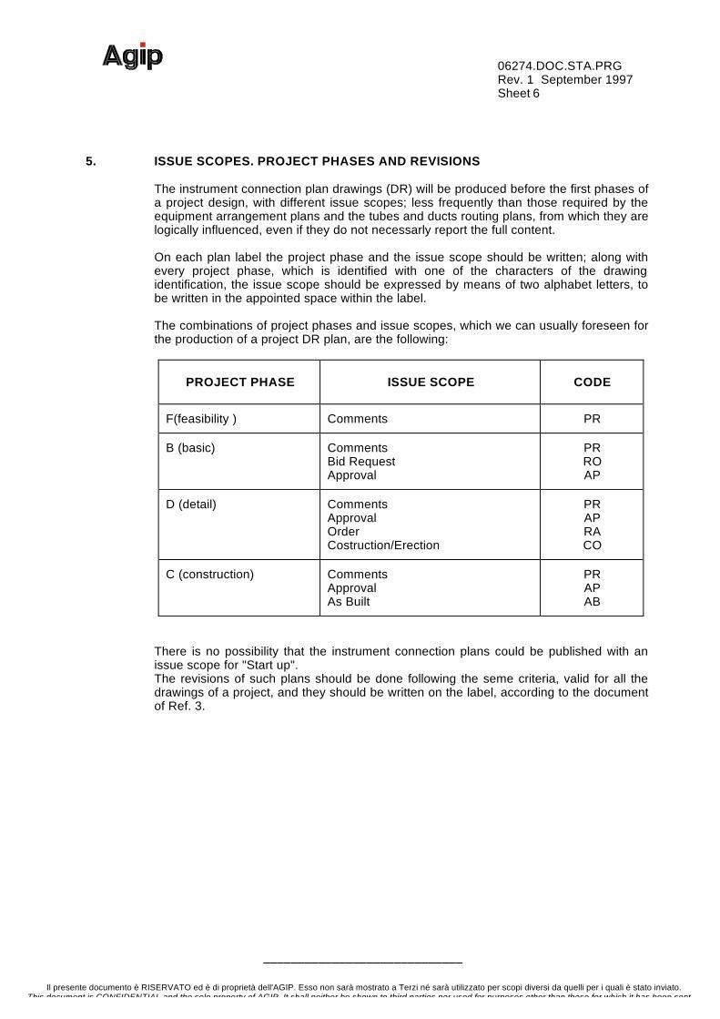
5. ISSUE SCOPES. PROJECT PHASES AND REVISIONS
The instrument connection plan drawings (DR) will be produced before the first phases ofa project design, with different issue scopes; less frequently than those required by theequipment arrangement plans and the tubes and ducts routing plans, from which they arelogically influenced, even if they do not necessarly report the full content.
On each plan label the project phase and the issue scope should be written; along withevery project phase, which is identified with one of the characters of the drawingidentification, the issue scope should be expressed by means of two alphabet letters, tobe written in the appointed space within the label.
The combinations of project phases and issue scopes, which we can usually foreseen forthe production of a project DR plan, are the following:
PROJECT PHASE ISSUE SCOPE CODE
F(feasibility ) Comments PR
B (basic) CommentsBid RequestApproval
PRROAP
D (detail) CommentsApprovalOrderCostruction/Erection
PRAPRACO
C (construction) CommentsApprovalAs Built
PRAPAB
There is no possibility that the instrument connection plans could be published with anissue scope for "Start up".The revisions of such plans should be done following the seme criteria, valid for all thedrawings of a project, and they should be written on the label, according to the documentof Ref. 3.
06274.DOC.STA.PRGRev. 1 September 1997Sheet 7
–––––––––––––––––––––––––––––
Il presente documento è RISERVATO ed è di proprietà dell'AGIP. Esso non sarà mostrato a Terzi né sarà utilizzato per scopi diversi da quelli per i quali è stato inviato.This document is CONFIDENTIAL and the sole property of AGIP. It shall neither be shown to third parties nor used for purposes other than those for which it has been sent.
6. CONTENT
This chapter presents the content, the execution criteria, the reference symbols and thedifferent detail levels re]ated to the issue phase of the document of this standard.It is important to keep in mina that, in the instrument connection drawings, also theinstrument already inserted in the safety layout drawings should appear.
6.1. Application
The i ns trument con necti on plan w il l present sufficently detailed i nformation on theplant layout in order to allow:
• a definition of the topographic description of all the instruments requiring an electricaland/or pneumatic interconnession (safety ones included);
• a definition and location of eventual locai support racks for instruments, or a portion ofthe seme, compatibly with the space available within the plant;
• a definition and location of junction boxes for the collection and connection of near andcompatible instrument cables, in order to sena the signals through a single cable, tobe connected with the instrument panels;
• a definition and location of the instruments pneumatic feeding manifolds and of thedetachment po in t of the tubing connecting the mani fold to the instrument ;
• representing a reference during the instrument connection mounting and permitting afast finding and accessibility in case of accident or during the plant maintenance;
• a definition of the cable route planimetrie drawings and, in particular, of the cable traysof instrument cables or air, nitrogen or gas distribution tubing, related to theinstruments;
• a definition or a contributi on to the producti on of the drawing (or of the tables)defining the cable or tubing routing;
• a contribution to the instrument list production, with particular regard to topologie, dataand to the definition of the racks and the boxes connected to them. So the quality ofthese fast ones can be defined, in view of the purchasing needs, for their beig tipicallyobjects depending on the layout.
06274.DOC.STA.PRGRev. 1 September 1997Sheet 8
–––––––––––––––––––––––––––––
Il presente documento è RISERVATO ed è di proprietà dell'AGIP. Esso non sarà mostrato a Terzi né sarà utilizzato per scopi diversi da quelli per i quali è stato inviato.This document is CONFIDENTIAL and the sole property of AGIP. It shall neither be shown to third parties nor used for purposes other than those for which it has been sent.
6.2 Description and execution criteria
The instrument connection plans (DR) representthe plan arrangement of all the plantinstruments requiring an electric and/or pneumatic interconnession, both inside thebuildings or the platforms, and on the "round, with the presence of civil works andstructures, and with a particular reference to their topographic position. The instrumentalready positioned on the safety drawings are included too.
DR plans should, above al1, present information allowing the identification of theinstrument and the implementing of the interconnession design between instrument andconnecting boxes or manifolds; of course the information will be more complete when weget closer to the final issue of the drawings.
The instrument connection plans always trave the seme content, independently from thecomplexity of the plant they are made for, and from the scope they are produced fon
The instrument arrangement is done by overimposing to every single copy of the processequipment arrangement drawing, or in particular cases on the piping route drawing, thesuitable item symbols; these, for a good reading of the drawing, can be divided into twoor three groups (and therefore create two or three different drawings) of omogeneusitems or of common management:
a) electrical or electro-pneumatic instrumentsb) pneumatic or electro-pneumatic instrumentsc) fusitele plugs network (always on a separate document).
If for the seme plant area three documenta are produced, each one for a set of items, asAgip designing methods preferably require, these are given the following names:
a) Electrical instrument connection plan.b) Pneumatic instrument connection plan.c) Fusible plug network connection plan.
The first two mentioned drawings are usua]ly made up of a graphic part and a table part,describing the grouping of the instruments presented in the graphic part.
The instrument connection plans should always be separately identified, every time theplant area represented is changed; but if one of the areas needs to be subdivided amongseveral sheets, these must trave the seme drawing identification and a progressive sheetnumber starting from 1. Naturally a suitable scale should be chosen, in order to reducethe number of sheets , whi le al lowing a good interpreting of the whole plant drawn.
In the case the plant complexity permits it, it is advisable that the scale adopted for thesafety layout drawings production should also be used for the electrical and pneumaticinstrument connection drawings, and for the fusitele plug ones.
06274.DOC.STA.PRGRev. 1 September 1997Sheet 9
–––––––––––––––––––––––––––––
Il presente documento è RISERVATO ed è di proprietà dell'AGIP. Esso non sarà mostrato a Terzi né sarà utilizzato per scopi diversi da quelli per i quali è stato inviato.This document is CONFIDENTIAL and the sole property of AGIP. It shall neither be shown to third parties nor used for purposes other than those for which it has been sent.
6.2.1. Graphic part
The instrument connection plans should present all the instruments requiring an electricalinterconnession, or a interconnession to the pneumatic network, which are located in theplant (included the ones already placed in the safety drawings), NOT in scale, indepentlyfrom their phisical size.
Along with the instruments these plans should trave all the locai racks, or the instrumentcontainers, the cable junction boxes, the pneumatic feeding manifolds till the instrumentair barrels, indication every air detachment to the users.
All the instrument and the mentioned items will trave to be identified, writing theidentification of every single one, with no blank space or any kind of separation, on asuitable rim, located as near as possible to the item itself and placed in such a way tomake the reading as easy as pos sible (the i de n tifi c ati on al ign emen t cou l d makethe reading much easier). If a symbol covering several instruments is used, we need topiace its identifications within a single rectangle. Naturally, in this case, all the instrumentshould be placed at the seme elevation.
No identification is required for the fuse plugs. The instruments are marked with letters, inagreement with the document in Ref. 2.
In the case of overimposed items, there is the need to point out the covered one bymoving its symbol a little bit, and it is important to highlight the identification of each one,putting the related identifications one over the other, vertically, following the items order.
In the plans related to the pneumatic instruments and to the fuse plugs, there is the needto report and identify the entire tubing (and the manifolds in particular), and to point outthe type of fluid contained and its pressure, expressed in Barg.
The tubing identification criteria should follow the one already mentioned for theidentification of the process linee. All the feeding detachments from the manifolds shouldbe marked with letters, in order to write, in the suitable table, the instrument they aredirected tot
When possible, we suggest giving the manifold a progressive multiple of a hundred. Insuch a way we can use the artifice of numbering the detachments with the seme firstcharacter of the progressive given to the manifold.In the fuse plugs network connection drawings it is important to highligh the equipmentrequiring the presence of dedicated caps, locating around the equipment map the relatedtubing and, connected to this, the caps symbols.Also in the other types of instrument connection plans we need to highlight, and identify,the equipment influencing the instruments arrangement.
It is also possible to avoid representing, on the instrument connection drawing, themechanical or electric equipments which trave no influence on the instrument presence ,on the i nstrument mounting and maintenance.
06274.DOC.STA.PRGRev. 1 September 1997Sheet 10
–––––––––––––––––––––––––––––
Il presente documento è RISERVATO ed è di proprietà dell'AGIP. Esso non sarà mostrato a Terzi né sarà utilizzato per scopi diversi da quelli per i quali è stato inviato.This document is CONFIDENTIAL and the sole property of AGIP. It shall neither be shown to third parties nor used for purposes other than those for which it has been sent.
To make the work clear, we should avoid representing the route of the cable traysreserved for instrument cables, expecially in the case of a pneumatic instrumentconnection and of a fuse plug network drawing .
Instruments, manifolds and junction boxes need to be placed according to the realposition they trave within the plant, even if the indication of the instrument coordinatesisn't usually prescribed; we should only make explicit, by means of general notes, thedistance limite for the position of some individual instrument types, from ceilings, floors,walls or process connections.
Conversely, all the instruments should present the elevation they are placed at; suchelevation should be written next to the instrument identification, above the fine connectingthe instrument symbol to its identification.Coordinates and elevations will be expressed in mm. A greater precision than + 50 mm.is not required
As for the sensore, there is the need to point out if they are placed under the floating flooror into the false ceiling, this is done by placing the typical writing "false ceiling" and"floating floor" under the instrument identification.
The portion of compressed air distribution network of the fuse plugs, normally circulatingin the rooms, should be identified with a continuous fine; the one underlying the floatingfloor, with a hatched fine; the one in the false ceiling with a dotted fine.As to the general part of the instrument connection drawing, what will be mentionedhereafter should appear in the drawing itself.
The drowings presents the orutes and the squares, the maintenance spaces, the stairs,the catwalks, the gride, the pipe racks, the gates and hinged or dismantable panels, thetemporary pluggings: The accesses, the trap-doors and the openings for the tubepassages inside the walls and the floors, having an impact on the instruments and therelated feeding, should be pointed out. The walls, the slabs, the paved areas, thecolumns do not require details or precise statements on the adopted type, but their soleexistence should result.
The ground elevations outside the buildings, and the internal slabls elevations of buldingsand platforms should always be indicated.The elevation should be expressed in mm., referred to the sea level.
In particular cases, the elevation could be expressed according to locai values, takingcare of writing the geographical reference on the datum point.
In the case of a plan presenting some Packages, made up of items whose identification isrequired, a rim with a hatched fine around all these package items should be drawn; arhombus should be placed on such a rim (the seme symbol as the one used for P&ID)and the package identification, if known.
When the planned plant area represents an addition to an already existing plant, or whensome are as or equipment to be implemented in the future are poi nted out for a newlyplanned plant, this must be shown with a suitable graphic symbol, indicating the differentimplementing time.
We recali and summarize here the information, already presented in detail in the Ref. 4document, that shou]d always appear in the drawing belonging to this standard:
• the geographical and the conventional north, the plant key map,• the main reference point (datum point)• the locai reference points, with a indication of the locai p]an coordinates,

06274.DOC.STA.PRGRev. 1 September 1997Sheet 11
–––––––––––––––––––––––––––––
Il presente documento è RISERVATO ed è di proprietà dell'AGIP. Esso non sarà mostrato a Terzi né sarà utilizzato per scopi diversi da quelli per i quali è stato inviato.This document is CONFIDENTIAL and the sole property of AGIP. It shall neither be shown to third parties nor used for purposes other than those for which it has been sent.
• the "columns network";• the plant surface limite:• the representation of all the work estraneus to the plant (i.e. electrical linee, sewages,
canale, etc.),
Take care of laying out the plant with the conventional north oriented upwards, and in anycase always keep the chosen arrangement for all the plans of all the plant areas.
The marking, with a small cloud, of all the DR portions which trave undergone somechanges since the previous revision is always required. In the cloud, the revision numberbringing the change about should appear within a suitable small triangle.
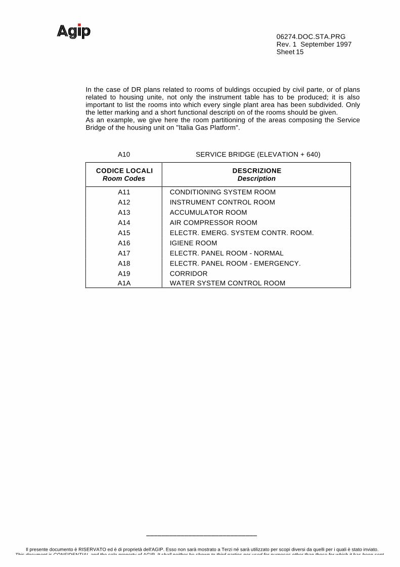
The instrument connection drawings, when related to housing units or to building porti ons usually hous i ng the staff, should gi ve a description of the different rooms functions, bythe use of a suitable table.
06274.DOC.STA.PRGRev. 1 September 1997Sheet 12
–––––––––––––––––––––––––––––
Il presente documento è RISERVATO ed è di proprietà dell'AGIP. Esso non sarà mostrato a Terzi né sarà utilizzato per scopi diversi da quelli per i quali è stato inviato.This document is CONFIDENTIAL and the sole property of AGIP. It shall neither be shown to third parties nor used for purposes other than those for which it has been sent.
6.2.2. Table part
The portion of the plan drawing placed above the label should be filled with the followinginformation, which follow the seme upward order:
• the key map• the drawing general notes• the table listing all instruments appearing in the plant• the table of the rooms, in the case of buildings or housing units• the interpreting key for the used symbols• the list of the plan drawings related with the interested one (i. e. the mechanical
equipment arrangement plan, the equipment arrangement and HVAC route drawing,the cable route drawings, etc.).
The key map should systematically appear in the plant detailed drawings, and it shouldbe hatched in the equivalent position to the one being detailed in the related plan.Among other things the general notes, in the specific case of the pneumatic instrumentsconnection plans, should trave a complete list of the spere branches comprised in thedrawing.
The instruments connection plans related to the electrical and to the pneumaticinstruments always require a table Bach, while the fuse plugs network connecting plansrequire no table.
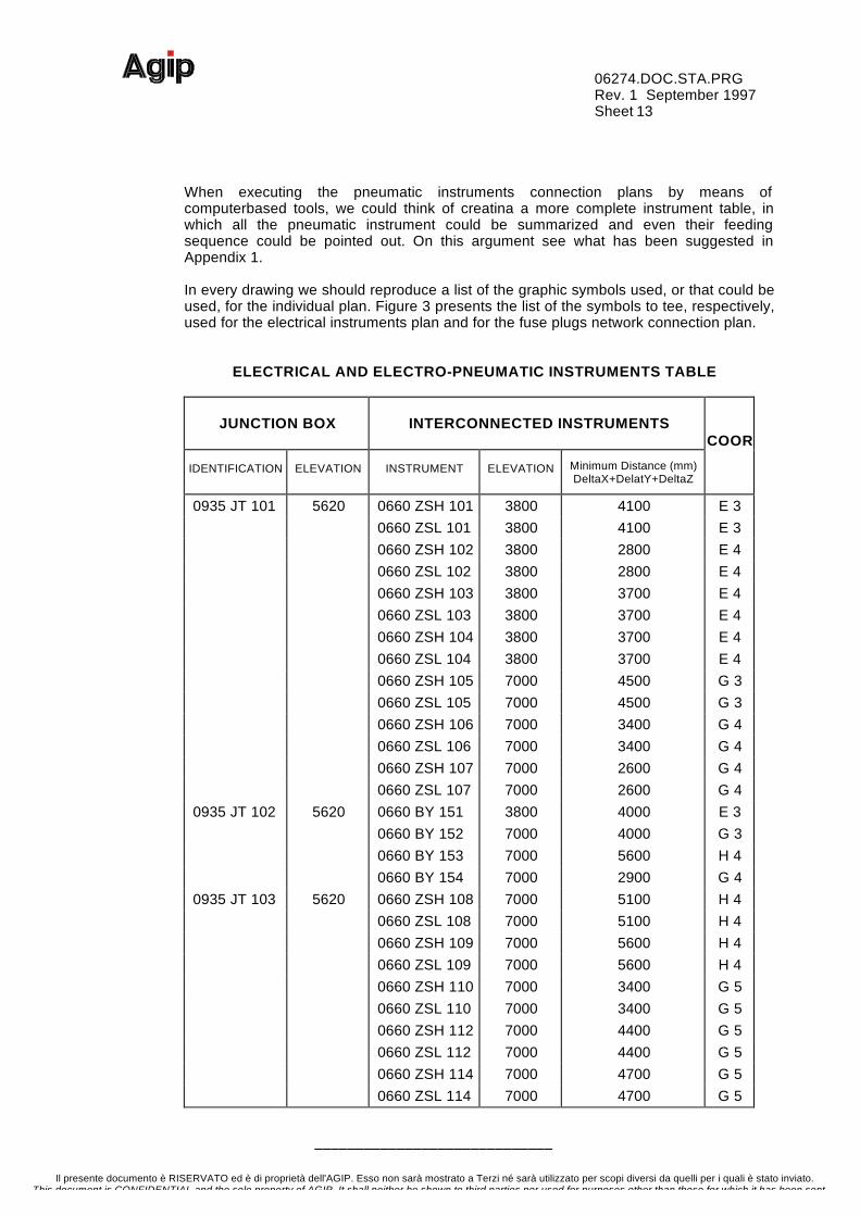
Here follows an example for the filling in of an electrical and electro-pneumaticinstruments table, related to the contents of the Italia Gas Platform Base Bridge plan, andthen an example of a pneumatic and electro-pneumatic instruments table for the ServiceBridge of the seme platform. Both table contents corresponds to the contents of Figures Iand 2.
The electric and electro-pneumatic instruments table presents a list of all the instrumentsappearing on a single plan, reported with the elevation they are placed at, with thecoordinates on the sheet, and with the distance saparating every single instrument fromthe junction box the interested cable is connected to, expressed as a sum of the absolutevalues of the X, Y, and Z incrementa of the related geographic coordinates.
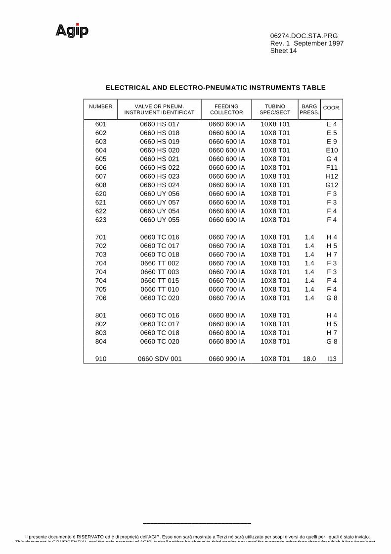
The electrical instruments appear in the table according to a growing identification order,within the junction box they are connected totThe instruments unconneted to a junction box, or connected to a box not appearing in theplan, should be listed before those connected to a box.The pneumatic and electro-pneumatic intruments table presents a list of thoseinstruments connected to a junction located on one of the instruments air manifolds,either a feeding one or a set or a signal sending one, only.
06274.DOC.STA.PRGRev. 1 September 1997Sheet 13
–––––––––––––––––––––––––––––
Il presente documento è RISERVATO ed è di proprietà dell'AGIP. Esso non sarà mostrato a Terzi né sarà utilizzato per scopi diversi da quelli per i quali è stato inviato.This document is CONFIDENTIAL and the sole property of AGIP. It shall neither be shown to third parties nor used for purposes other than those for which it has been sent.
When executing the pneumatic instruments connection plans by means ofcomputerbased tools, we could think of creatina a more complete instrument table, inwhich all the pneumatic instrument could be summarized and even their feedingsequence could be pointed out. On this argument see what has been suggested inAppendix 1.
In every drawing we should reproduce a list of the graphic symbols used, or that could beused, for the individual plan. Figure 3 presents the list of the symbols to tee, respectively,used for the electrical instruments plan and for the fuse plugs network connection plan.
ELECTRICAL AND ELECTRO-PNEUMATIC INSTRUMENTS TABLE
JUNCTION BOX INTERCONNECTED INSTRUMENTSCOOR
IDENTIFICATION ELEVATION INSTRUMENT ELEVATION Minimum Distance (mm)DeltaX+DelatY+DeltaZ
0935 JT 101 5620 0660 ZSH 101 3800 4100 E 30660 ZSL 101 3800 4100 E 30660 ZSH 102 3800 2800 E 40660 ZSL 102 3800 2800 E 40660 ZSH 103 3800 3700 E 40660 ZSL 103 3800 3700 E 40660 ZSH 104 3800 3700 E 40660 ZSL 104 3800 3700 E 40660 ZSH 105 7000 4500 G 30660 ZSL 105 7000 4500 G 30660 ZSH 106 7000 3400 G 40660 ZSL 106 7000 3400 G 40660 ZSH 107 7000 2600 G 40660 ZSL 107 7000 2600 G 4
0935 JT 102 5620 0660 BY 151 3800 4000 E 30660 BY 152 7000 4000 G 30660 BY 153 7000 5600 H 40660 BY 154 7000 2900 G 4
0935 JT 103 5620 0660 ZSH 108 7000 5100 H 40660 ZSL 108 7000 5100 H 40660 ZSH 109 7000 5600 H 40660 ZSL 109 7000 5600 H 40660 ZSH 110 7000 3400 G 50660 ZSL 110 7000 3400 G 50660 ZSH 112 7000 4400 G 50660 ZSL 112 7000 4400 G 50660 ZSH 114 7000 4700 G 50660 ZSL 114 7000 4700 G 5
06274.DOC.STA.PRGRev. 1 September 1997Sheet 14
–––––––––––––––––––––––––––––
Il presente documento è RISERVATO ed è di proprietà dell'AGIP. Esso non sarà mostrato a Terzi né sarà utilizzato per scopi diversi da quelli per i quali è stato inviato.This document is CONFIDENTIAL and the sole property of AGIP. It shall neither be shown to third parties nor used for purposes other than those for which it has been sent.
ELECTRICAL AND ELECTRO-PNEUMATIC INSTRUMENTS TABLE
NUMBER VALVE OR PNEUM.INSTRUMENT IDENTIFICAT
FEEDINGCOLLECTOR
TUBINOSPEC/SECT
BARGPRESS.
COOR.
601 0660 HS 017 0660 600 IA 10X8 T01 E 4602 0660 HS 018 0660 600 IA 10X8 T01 E 5603 0660 HS 019 0660 600 IA 10X8 T01 E 9604 0660 HS 020 0660 600 IA 10X8 T01 E10605 0660 HS 021 0660 600 IA 10X8 T01 G 4606 0660 HS 022 0660 600 IA 10X8 T01 F11607 0660 HS 023 0660 600 IA 10X8 T01 H12608 0660 HS 024 0660 600 IA 10X8 T01 G12620 0660 UY 056 0660 600 IA 10X8 T01 F 3621 0660 UY 057 0660 600 IA 10X8 T01 F 3622 0660 UY 054 0660 600 IA 10X8 T01 F 4623 0660 UY 055 0660 600 IA 10X8 T01 F 4
701 0660 TC 016 0660 700 IA 10X8 T01 1.4 H 4702 0660 TC 017 0660 700 IA 10X8 T01 1.4 H 5703 0660 TC 018 0660 700 IA 10X8 T01 1.4 H 7704 0660 TT 002 0660 700 IA 10X8 T01 1.4 F 3704 0660 TT 003 0660 700 IA 10X8 T01 1.4 F 3704 0660 TT 015 0660 700 IA 10X8 T01 1.4 F 4705 0660 TT 010 0660 700 IA 10X8 T01 1.4 F 4706 0660 TC 020 0660 700 IA 10X8 T01 1.4 G 8
801 0660 TC 016 0660 800 IA 10X8 T01 H 4802 0660 TC 017 0660 800 IA 10X8 T01 H 5803 0660 TC 018 0660 800 IA 10X8 T01 H 7804 0660 TC 020 0660 800 IA 10X8 T01 G 8
910 0660 SDV 001 0660 900 IA 10X8 T01 18.0 I13
06274.DOC.STA.PRGRev. 1 September 1997Sheet 15
–––––––––––––––––––––––––––––
Il presente documento è RISERVATO ed è di proprietà dell'AGIP. Esso non sarà mostrato a Terzi né sarà utilizzato per scopi diversi da quelli per i quali è stato inviato.This document is CONFIDENTIAL and the sole property of AGIP. It shall neither be shown to third parties nor used for purposes other than those for which it has been sent.
In the case of DR plans related to rooms of buldings occupied by civil parte, or of plansrelated to housing unite, not only the instrument table has to be produced; it is alsoimportant to list the rooms into which every single plant area has been subdivided. Onlythe letter marking and a short functional descripti on of the rooms should be given.As an example, we give here the room partitioning of the areas composing the ServiceBridge of the housing unit on "Italia Gas Platform".
A10 SERVICE BRIDGE (ELEVATION + 640)
CODICE LOCALIRoom Codes
DESCRIZIONEDescription
A11 CONDITIONING SYSTEM ROOMA12 INSTRUMENT CONTROL ROOMA13 ACCUMULATOR ROOMA14 AIR COMPRESSOR ROOMA15 ELECTR. EMERG. SYSTEM CONTR. ROOM.A16 IGIENE ROOMA17 ELECTR. PANEL ROOM - NORMALA18 ELECTR. PANEL ROOM - EMERGENCY.A19 CORRIDORA1A WATER SYSTEM CONTROL ROOM
06274.DOC.STA.PRGRev. 1 September 1997Sheet 16
–––––––––––––––––––––––––––––
Il presente documento è RISERVATO ed è di proprietà dell'AGIP. Esso non sarà mostrato a Terzi né sarà utilizzato per scopi diversi da quelli per i quali è stato inviato.This document is CONFIDENTIAL and the sole property of AGIP. It shall neither be shown to third parties nor used for purposes other than those for which it has been sent.
7. GRAPHIC SYMBOLS
7.1. General description
For an easy reading of the instrument connection plan drawings these should bereproduced, for most parte, on drawing paper, using a very light hand, if handmade; orthey should be plotted with a very thin fine (0.2 mm.) if produced with the aid ofcomputer-based tools.
That is all the graphic parts related to roads, squares, building shapes, walls, columns,stairs, cable trays, gardens, gravines, "round water works, subterranean works ,structural works , gride , el evation definiti ons , column networks , internal hatchings,area limite, symbols of general kind which are thaught as necessary for the instrumentsarrangement should be reproduced using a very thin fine.
An existing plant "future" or "newly planned" parts should be highlited with a thin hatching(if handmade), or with some dots (if CAD produced) entirely covering the interested area.
These drawings, used to control the existence and the correct arrangement of all theinstruments, should absolutely be devoided of all the information not helping a goodreading of the seme.
The junction boxes identifications hould be written above a fine, possibly an orizontal one,as near as possible to the seme, and 0.2 mm. thick.
The single or paired off instruments identifications should be written inside a rectangle, asnear as possible to them, drawn with a 0.2 mm. thick fine and connected to theinstrument, or to the instruments pair, by means of a fine of the seme thickness.
The scale to be used for the production of the instrument connection plans should tee, ifpossible, the seme as the one used to produce the mechanical equipment arrangementplan, from which the rest of the drawing has been derived, including the equipment butleaving out the related dimensionings.
In some cases we can use the piping arrangement plan, if this gives a valid help indetermining the instrument valves location, or that of other instruments located on thepiping.
Therefore the scalee will vary from a minimum of 1:25 to a maximum of 1:1000, withintermediate values of 1:33.3, 1:50, 1:75. Different values will be exceptionally used, ifrequired by a need of clarity of the work.
06274.DOC.STA.PRGRev. 1 September 1997Sheet 17
–––––––––––––––––––––––––––––
Il presente documento è RISERVATO ed è di proprietà dell'AGIP. Esso non sarà mostrato a Terzi né sarà utilizzato per scopi diversi da quelli per i quali è stato inviato.This document is CONFIDENTIAL and the sole property of AGIP. It shall neither be shown to third parties nor used for purposes other than those for which it has been sent.
7.2. Formats
The drawings are generally done in A1 format or, only if absolutely necessary, in A0format.
The information appearing on the format should respect the general criteria of spaceoccupation imposed by the Ref. 3 document, besides the drawing should be numberedaccording to the rules expressed by the Ref. 1 document.
As a con sequence the i n struments tabl es or the li st of presented rooms should bepositioned above the label, between the related drawings list and the notes.
7.3. Symbols
The plans require the use of some standard general symbols, whose appearance ispresented in figure 3 of this document. Other graphic symbols, related to the drawinggeneral part, and foreseen by the company standard, should appear on the drawingaccording to the seme criteria presented by the Ref. 4, 5, 6, and 7 documenta.
The instrument symbols should be used as they are, therefore they should not beinfluenced by the scale use to draw the plan.
In locating the symbols we should respect, as much as possible, the coordinetes wherethe instrument should be located; in any case we should avoid overimposing suchsymbols.
06274.DOC.STA.PRGRev. 1 September 1997Sheet 18
–––––––––––––––––––––––––––––
Il presente documento è RISERVATO ed è di proprietà dell'AGIP. Esso non sarà mostrato a Terzi né sarà utilizzato per scopi diversi da quelli per i quali è stato inviato.This document is CONFIDENTIAL and the sole property of AGIP. It shall neither be shown to third parties nor used for purposes other than those for which it has been sent.
8. ESTRACTIONS
When the instrument connection plans are made with computer-based tools (CAD) it ispossible to extract from them a series of information of general interest, andcomplementary to what has already been extracted from the process diagrams (PID);such information can be sent to the seme database previously prepared to hold theinformation extracted from PID, or they can be sent to a specific database.
The information which can be extracted from DR are:
• Instrument identification• Plan type• Item type• CAD code• Description of CAD code• Plant area• Belonging package• Geographic coordinated related to Datum Point (X and Y)• Elevation• Cable junction box• Instrument air feeding manifold• Detachment from feeding manifold• Signal sending manifold• Detachment from signal sending manifold• Old, present or future implementing• Added notes to the symbol• Local coordinated related to locai walls• DR plan identification• DR sheet, revision and issue scope• Coordinates in DR sheet
The mentioned information should all be visualized at the seme time, in the form of aCAD printing, and extracted, as a "file" to be sent to a data base. The printing has theonly purpose of allowing a fast control on the plan correct execution.
06274.DOC.STA.PRGRev. 1 September 1997Sheet 19
–––––––––––––––––––––––––––––
Il presente documento è RISERVATO ed è di proprietà dell'AGIP. Esso non sarà mostrato a Terzi né sarà utilizzato per scopi diversi da quelli per i quali è stato inviato.This document is CONFIDENTIAL and the sole property of AGIP. It shall neither be shown to third parties nor used for purposes other than those for which it has been sent.
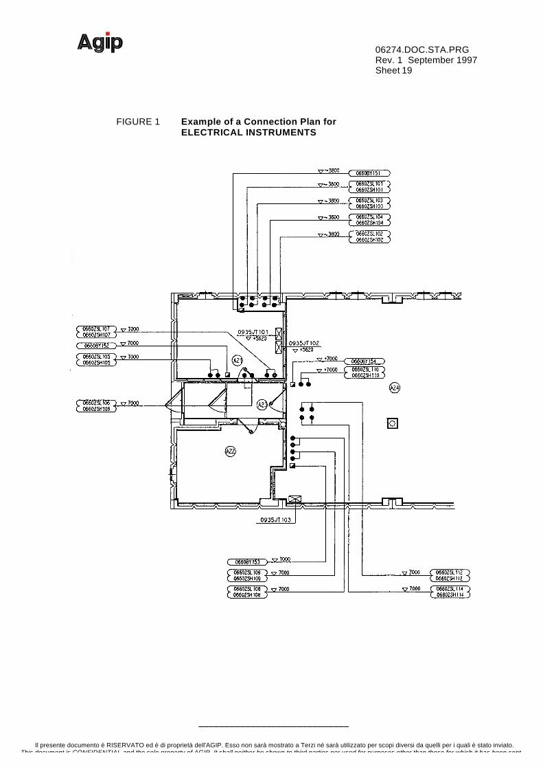
FIGURE 1 Example of a Connection Plan forELECTRICAL INSTRUMENTS

06274.DOC.STA.PRGRev. 1 September 1997Sheet 20
–––––––––––––––––––––––––––––
Il presente documento è RISERVATO ed è di proprietà dell'AGIP. Esso non sarà mostrato a Terzi né sarà utilizzato per scopi diversi da quelli per i quali è stato inviato.This document is CONFIDENTIAL and the sole property of AGIP. It shall neither be shown to third parties nor used for purposes other than those for which it has been sent.
FIGURE 2 Example of a Connection Plan forPNEUMATIC INSTRUMENTS
File S06274IC.DWG(LATER)
06274.DOC.STA.PRGRev. 1 September 1997Sheet 21
–––––––––––––––––––––––––––––
Il presente documento è RISERVATO ed è di proprietà dell'AGIP. Esso non sarà mostrato a Terzi né sarà utilizzato per scopi diversi da quelli per i quali è stato inviato.This document is CONFIDENTIAL and the sole property of AGIP. It shall neither be shown to third parties nor used for purposes other than those for which it has been sent.
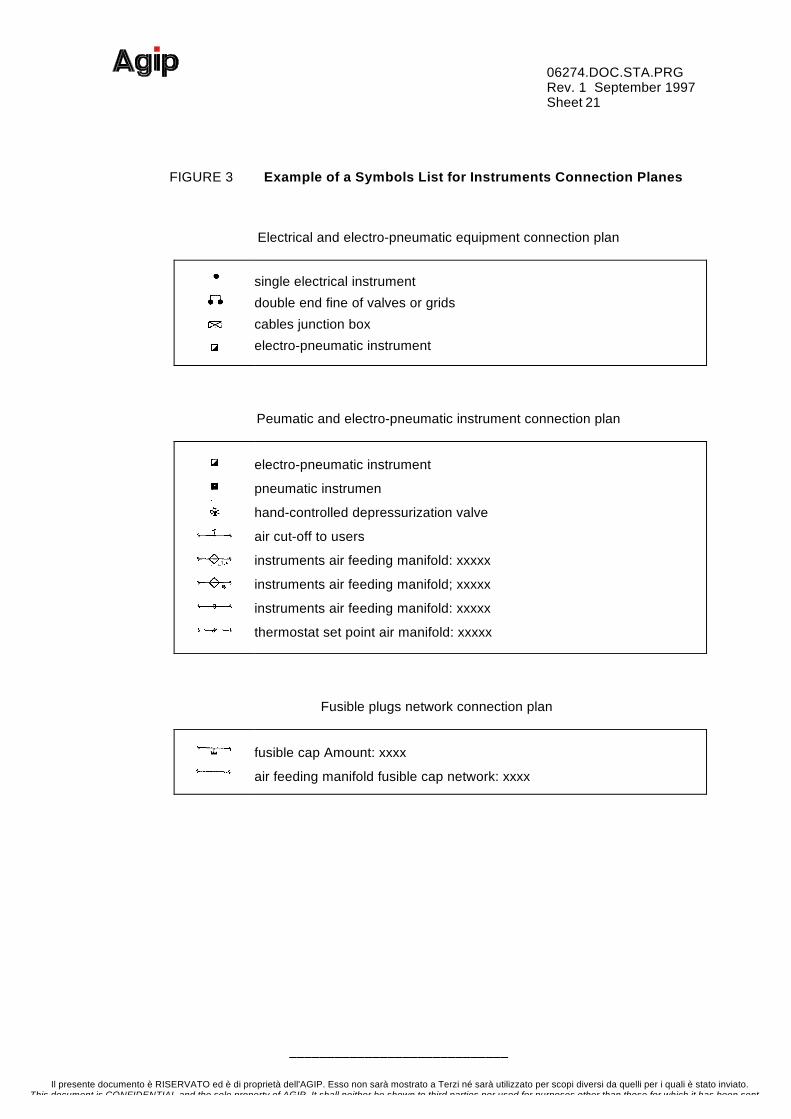
FIGURE 3 Example of a Symbols List for Instruments Connection Planes
Electrical and electro-pneumatic equipment connection plan
single electrical instrument
double end fine of valves or grids
cables junction box
electro-pneumatic instrument
Peumatic and electro-pneumatic instrument connection plan
electro-pneumatic instrument
pneumatic instrumen
hand-controlled depressurization valve
air cut-off to users
instruments air feeding manifold: xxxxx
instruments air feeding manifold; xxxxx
instruments air feeding manifold: xxxxx
thermostat set point air manifold: xxxxx
Fusible plugs network connection plan
fusible cap Amount: xxxx
air feeding manifold fusible cap network: xxxx
06274.DOC.STA.PRGRev. 1 September 1997Sheet 22
–––––––––––––––––––––––––––––
Il presente documento è RISERVATO ed è di proprietà dell'AGIP. Esso non sarà mostrato a Terzi né sarà utilizzato per scopi diversi da quelli per i quali è stato inviato.This document is CONFIDENTIAL and the sole property of AGIP. It shall neither be shown to third parties nor used for purposes other than those for which it has been sent.
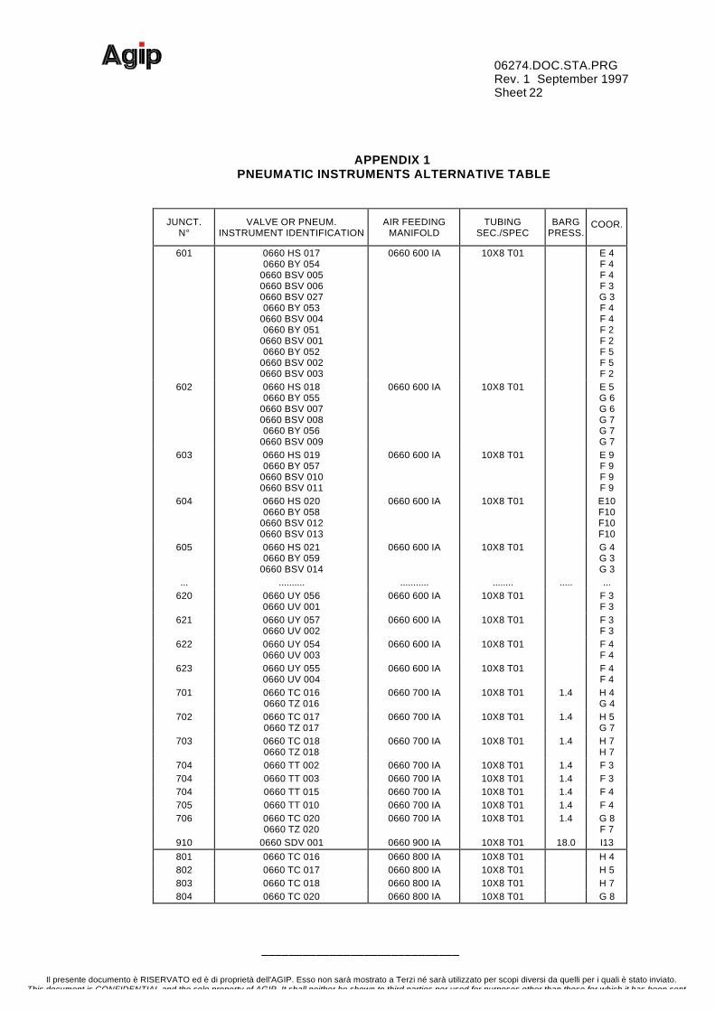
APPENDIX 1PNEUMATIC INSTRUMENTS ALTERNATIVE TABLE
JUNCT.N°
VALVE OR PNEUM.INSTRUMENT IDENTIFICATION
AIR FEEDINGMANIFOLD
TUBINGSEC./SPEC
BARGPRESS.
COOR.
601 0660 HS 0170660 BY 054
0660 BSV 0050660 BSV 0060660 BSV 0270660 BY 053
0660 BSV 0040660 BY 051
0660 BSV 0010660 BY 052
0660 BSV 0020660 BSV 003
0660 600 IA 10X8 T01 E 4F 4F 4F 3G 3F 4F 4F 2F 2F 5F 5F 2
602 0660 HS 0180660 BY 055
0660 BSV 0070660 BSV 0080660 BY 056
0660 BSV 009
0660 600 IA 10X8 T01 E 5G 6G 6G 7G 7G 7
603 0660 HS 0190660 BY 057
0660 BSV 0100660 BSV 011
0660 600 IA 10X8 T01 E 9F 9F 9F 9
604 0660 HS 0200660 BY 058
0660 BSV 0120660 BSV 013
0660 600 IA 10X8 T01 E10F10F10F10
605 0660 HS 0210660 BY 059
0660 BSV 014
0660 600 IA 10X8 T01 G 4G 3G 3
... .......... ........... ........ ..... ...620 0660 UY 056
0660 UV 0010660 600 IA 10X8 T01 F 3
F 3621 0660 UY 057
0660 UV 0020660 600 IA 10X8 T01 F 3
F 3622 0660 UY 054
0660 UV 0030660 600 IA 10X8 T01 F 4
F 4623 0660 UY 055
0660 UV 0040660 600 IA 10X8 T01 F 4
F 4701 0660 TC 016
0660 TZ 0160660 700 IA 10X8 T01 1.4 H 4
G 4702 0660 TC 017
0660 TZ 0170660 700 IA 10X8 T01 1.4 H 5
G 7703 0660 TC 018
0660 TZ 0180660 700 IA 10X8 T01 1.4 H 7
H 7704 0660 TT 002 0660 700 IA 10X8 T01 1.4 F 3704 0660 TT 003 0660 700 IA 10X8 T01 1.4 F 3704 0660 TT 015 0660 700 IA 10X8 T01 1.4 F 4705 0660 TT 010 0660 700 IA 10X8 T01 1.4 F 4706 0660 TC 020
0660 TZ 0200660 700 IA 10X8 T01 1.4 G 8
F 7910 0660 SDV 001 0660 900 IA 10X8 T01 18.0 I13801 0660 TC 016 0660 800 IA 10X8 T01 H 4802 0660 TC 017 0660 800 IA 10X8 T01 H 5803 0660 TC 018 0660 800 IA 10X8 T01 H 7804 0660 TC 020 0660 800 IA 10X8 T01 G 8


![[Free Scores.com] Antonio Lauro El Negrito 4136 (1)](https://static.fdocumenti.com/doc/165x107/53f8f9f3dab5cad23a8b486b/free-scorescom-antonio-lauro-el-negrito-4136-1.jpg)