
Резервная копия презентация геосмарт 2016 en …Russia occupies 174...
21
Transcript of Резервная копия презентация геосмарт 2016 en …Russia occupies 174...


South Ural State University(National research university)
Founded in 1943 as Chelyabinsk Mechanical Engineering Institute, the university was reorganized into Chelyabinsk Polytechnic Institute in 1951, and in 1990 it became the Chelyabinsk State Technical University.Since 1997, the university is known as South Ural State University. In 2010 it was assigned the status as a National Research University. Official website: www.susu.ac.ru
Kuban State Agrarian University
It is one of the recognized leaders in higher agricultural education in Russia.�e largest university in the south of Russia occupies 174 hectares in the city of Krasnodar , a region of the Winter Olympic Games "Sochi - 2014" near the Black and Azov Seas. �e University is represented by a campus with 20 dormitories and 20 academic buildings for education and everyday lives of students, it has sports facilities on the Black Sea and Russia 's two largest agricul-tural technoparks more than 120000 m2 in area . 22 thousand students from 23 countries are studying at the university. �e university has a podfak (Center for the Study of Russian Language for Foreign Students). Within the program of academic mobility of students the higher education institution has partners among universities in 44 countries in Europe and Asia. Official website: www.kubsau.ru
“Strela” Ltd.
“Strela” Ltd. is the only authorized distributor of LSTC Corporation in Russia and CIS countries. LS-DYNA is a multi-purpose finite-element complex for the analysis of highly nonlinear and rapid processes in problems of mechanics of solid and liquid bodies. �e company today has a staff of highly qualified engineers to conduct numerical calculations of stress-strain state of structural elements. �e company acquired sufficient experience in the numerical modeling of the behavior of the constructions at any stage of their life cycle (design, production, maintenance, emergency loading, including fire, modification, disassembly). Official website: www.lsdyna.ru
MIDAS Informational Technology Co., Ltd. (MIDAS IT)
�e prime focus of MIDAS Information Technology Co., Ltd. (MIDAS IT) includes civil/structural/mechanical engineering so�ware development along with analysis & design support.�e MIDAS Programs have been developed since 1989 and used commercially since 1996. �eir reliability has been established through applying them over a countless number of real projects.�e company was officially incorporated in September 1, 2000, and it was formerly operated under the auspices of POSCO Group. MIDAS IT also has corporate offices in Beijing, Shanghai, Detroit, Dallas, Europe, India and Japan. Official website: www.midasit.ru
Partners
Allnamics
“Allnamics consists of a group of experts with an extensive and more than 40 years experience in Geotechnical Engineering, Monitoring and Pile Testing all over the world, onshore and offshore.
Pa
rt1
Part 1 | 5
Part 1 | 6
ActivitiesPa
rt1
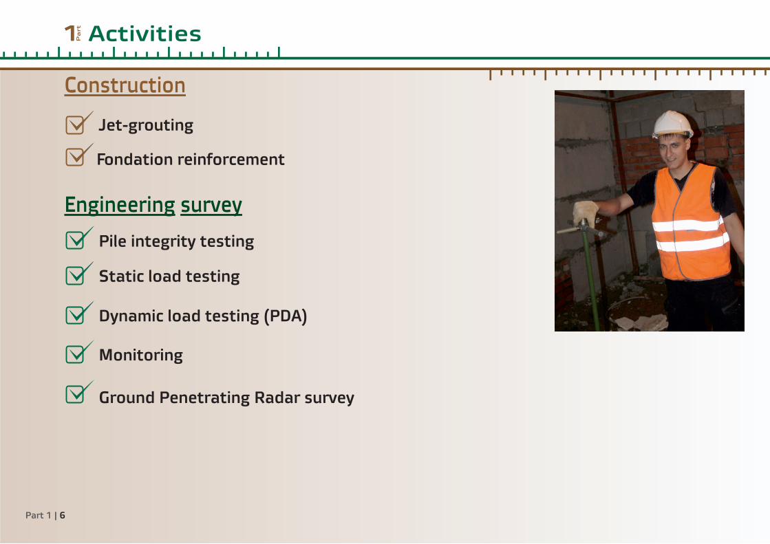
Jet-grouting
Pile integrity testing
Static load testing
Dynamic load testing (PDA)
Monitoring
Ground Penetrating Radar survey
Construction
Engineering survey
Fondation reinforcement

ConstructionPa
rt2
Part 2 | 7

Jet-grouting
Jet grouting is a grouting technique that creates in situ geometries of soilcrete (grouted soil), using a grouting monitor attached to the end of a drill stem. �e jet grout monitor is advanced to the maximum treatment depth, at which time high velocity grout jets (and sometimes water and air) are initiated from ports in the side of the monitor. �e jets erode and mix the in situ soil as the drill stem and jet grout monitor are rotated and raised.�e jet grouting process constructs soilcrete panels, full columns or anything in between (partial columns) with designed strength and permeability. Jet grouting has been used to underpin existing founda-tions, construct excavation support walls, and construct slabs to seal the bottom of planned excavations.Jet grouting is effective across the widest range of
soil types of any grouting system, including silts and most clays. Because it is an erosion-based system, soil erodibility plays a major role in predicting geometry, quality and production. Cohesionless soils are typically more erodible by jet grouting than cohesive soils. Since the geometry and physical properties of the soilcrete are engineered, the properties of the soilcrete are readily and accurately predictable.Jet grouting's ability to construct soilcrete in confined spaces and around subsurface obstructions such as utilities, provides a unique degree of design flexibility. Indeed, in any situation requiring control of ground-water or excavation of unstable soil (water-bearing or otherwise) jet grouting should be considered.Usually, jet grouting can be accomplished without disrupting normal facility operations. �e recent
development of small containerized, highly mobile support equipment has enabled starting jet grouting work on the first day of setup, greatly reducing mobilization and demobilization costs. Jet grouting can o�en result in construction schedule savings.
Part 1 | 8

Part 2 | 9

Reasons for foundation reinforcement:- destruction of foundations as a result of design error- the effect of technical human activities- construction mistakes, performed inside the building or next to it- the increased loading on foundations
Foundation reinforcement
�e company uses different types of machines (Sterh, Comacchio) for working in confined spaces. �is allows us to perform reinforcement with different types of piles (Titan, Jet, Injection) as well as with steel piles.�e main criteria of high-quality works at foundation reinforcement of our company are:
- geotechnical justification of existing foundations reinforcement method- geomonitoring conduction (including monitoring of buildings in the construction zone)- evaluation of the dynamic component of the construction process- evaluation of the conformity of foundation soil to design project
Part 1 | 10

Part 2 | 11

Engineering survey3 Pa
rt
Part 3 | 12

Pile integrity testing (ASTM D5882 – 07)
Pile Integrity Testing (PIT) is a low-strain and non-destructive integrity test method which only involves the impact from a small hand-held hammer. �is low-strain test can be applied to any concrete piles (eg. Pre-stressed concrete piles, drilled sha�s, auger cast piles, concrete filled pipe piles). Acceleration and stress wave which generated by the i m p a c t o f s m a l l h a n d h e l d h a m m e r i s t h e i n p u t o f t h i s t e s t m e t h o d .
Based on stress wave propagation and reflection theory; a stress wave (compression / tension) in a uniform rod is reflected if the wave encounters an impedance change. Structurally sound sha�s made with concrete should have reflection wave from sha� toe with only minor variations of the record amplitudes between impact and toe reflection. Sound sha�s may also be indicated by negative velocity reflections which are o�en caused by bulges (so�er soils), auger-wobble or excess grout pressure allow for an enlargement of the bored hole.
Part 3 | 13

Static load testing (ASTM D1143/D1143M – 07, D3689 – 07)
�e monitoring and quality of Static Load Tests has been significantly enhanced in terms of safety, reliability and accuracy of the results by the automa-tion of:џ Measurement and recording of pile settlement
and applied loadingџ Control of the applied loadџ Controlled change of load subject to preset
criteriaEach system consists of load and displacement
sensors, a microprocessor based data log-ger/controller, and a hydraulically operated device for application of load. �e equipment is capable of measuring and recording the load automatically during a test at pre-set intervals of typically 1 minute, to a resolution of 1 kN and pile deflection to 0.01mm respectively. �e system automatically checks for continued safe operation every 2.5 seconds, making any appropriate corrections to the hydraulic pressure
in the jack to maintain the load to within very tight tolerances. �e equipment is powered by a rechargeable battery and is designed to be easily transportable. A computer can be used to monitor the load and deflection rate for immediate analysis, either locally or remotely, without interrupting the test. �e data may be presented on screen in tabular and graphical forms and printed results can be readily obtained, making reporting easy and fast. Over 3000 computer controlled loads tests have been carried out.
Part 3 | 14

Part 3 | 15

Dynamic load testing (PDA, ASTM D4945-12)Dynamic load testing is a method to assess a 's by applying a dynamic load to the pile head (a falling mass) while recording acceleration and strain on pile bearing capacitythe pile head. Dynamic load testing is a which is applied a�er pile installation. Dynamic load testing can be an attractive cost effective alternative to high strain dynamic testtraditional full scale static load testing. �e test generates data required by the foundation designer to provide assurance on the relative capacity of the foundation and can usually provide additional information that can be difficult to obtain via static load testing.�e procedure is standardized by ASTM D4945-00 Standard Test Method for of Piles. It may be performed on all piles, regardless of their High Strain Dynamic Testinginstallation method. In addition to bearing capacity, Dynamic Load Testing gives information on resistance distribution (sha� resistance and end bearing) and evaluates the shape and integrity of the foundation element.�e foundation bearing capacity results obtained with dynamic load tests correlate well with the results of performed on the same foundation elementstatic load testsADVANTAGES џ Can provide information difficult to obtain with static load tests, for example data on skin friction distribution and end bearing components of soil resistance. џ Can be used to assess pile integrity. џ Provides check of operating efficiency of driving hammer. џ Can be used to investigate anomalous driving behaviour. џ Cost effective and rapid to perform. џ Up to ten piles may be tested on a day. џ Causes minimum disruption to piling operations. џ No kentledge or anchor piles needed. џ Can be performed on piles installed over water. џ Piles do not need to be preselected for testing prior to installation.
Part 3 | 16

Part 3 | 17

MonitoringImplementation of technical conditions monitoring is regulated by GOST 53778-2010 “Buildings and constructions. �e rules of survey and monitoring of technical conditions” and involves periodic visual inspection and measurements of dynamic parameters of the buildings and structures with the aim of:-control of object technical condition and timely adoption of measures for the elimination of arising negative factors leading to conditions deterioration;-identification of objects, on which there are changes in the stress-strain state of load-bearing structures and for which it is necessary to survey their technical condition;-tracking the extent and rate of change of object technical condition and adoption of emergency measures in the case of need to prevent its collapse. We will perform the following types of monitoring:-overall monitoring of the technical conditions of buildings and structures;-monitoring of technical condition of buildings and constructions, situated in the zone of influence of construction sites and natural and man-induced impacts;-monitoring of the technical conditions of buildings and structures, located in a limited operational or emergency condition;-monitoring of technical condition of unique, including high-rise and long-span buildings and structures. In the result of a next stage of monitoring you will receive Resolution on stage containing:-information about the condition of the building or of the structure at the moment;-comparison of parameters with the results of the previous period;-in case of parameters deterioration – guidelines for conducting an unscheduled examination;-in urgent cases – a list of measures to prevent the accident.
Part 3 | 18

“GEOSMART” company has advanced equipment and qualified personnel for GPR survey.With GPR it is possible to solve the following tasks:- determining the condition of concrete structures, finding old structures and evaluation of the new foundation;- analysis of roads (determining thickness of structural layers of the road coverage and type of reinforcement as well as identifying defects and flooding areas);
- localization of voids of artificial and natural origin;- determining the conditions of dams, dikes, bridges;- searching for gas, oil and water pipelines;- mapping of oil pollution of the soil, unauthorized tie-in in the gas and oil pipelines;- identification of places of disposal of industrial and household waste;- identification of local and areal archaeological sites (objects);
�e advantages of using GPR:- nondestructive testing instrument;- access to only one side of the concrete structure is required;- GPR provides data in “real-time” mode;- high performance speed, high detail;
Ground Penetrating Radar survey (ASTM D6432-11)
Part 3 | 19

Part 3 | 20

Completed objectsPa
rt4
Chelyabinsk
Novosibirsk
Tomsk
Sochi
Lipetsk
VladimirMoscow
Krasnodar
Nizhny Novgorod
Astana
Almaty
Part 4 | 21

Part 4 | 22
ContactsPa
rt4
Moscow officeStanislav Pavlovtel: +7-(499)-390-11-01e-mail: [email protected]
Astana officeAleksandr Lavrukhintel: +7-(771)-429-36-37e-mail: [email protected]
Chelyabinsk officeVyacheslav Dernovoy tel: +7-(351)-248-69-69e-mail: [email protected]