Z | Z Z | Z CAME ZA5.pdf · -1-documentazione tecnica s16 rev. 2.1 02/2001 ©came cancelli...
16
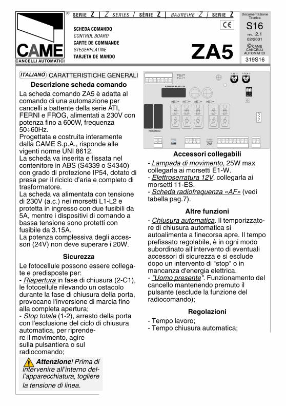
Documentazione Tecnica S16 rev. 2.1 02/2001 © CAME CANCELLI AUTOMATICI 319S16 SCHEDA COMANDO CONTROL BOARD CARTE DE COMMANDE STEUERPLATINE TARJETA DE MANDO SERIE Z | Z SERIES / SÉRIE Z | BAUREIHE Z | SERIE Z ZA5 CANCELLI AUTOMATICI Descrizione scheda comando La scheda comando ZA5 è adatta al comando di una automazione per cancelli a battente della serie ATI, FERNI e FROG, alimentati a 230V con potenza fino a 600W, frequenza 50÷60Hz. Progettata e costruita interamente dalla CAME S.p.A., risponde alle vigenti norme UNI 8612. La scheda va inserita e fissata nel contenitore in ABS (S4339 o S4340) con grado di protezione IP54, dotato di presa per il riciclo d’aria e completo di trasformatore. La scheda va alimentata con tensione di 230V (a.c.) nei morsetti L1-L2 e protetta in ingresso con due fusibili da 5A, mentre i dispositivi di comando a bassa tensione sono protetti con fusibile da 3.15A. La potenza complessiva degli acces- sori (24V) non deve superare i 20W. Sicurezza Le fotocellule possono essere collega- te e predisposte per: - Riapertura in fase di chiusura (2-C1), le fotocellule rilevando un ostacolo durante la fase di chiusura della porta, provocano l'inversione di marcia fino alla completa apertura; - Stop totale (1-2), arresto della porta con l'esclusione del ciclo di chiusura automatica, per riprende- re il movimento, agire sulla pulsantiera o sul radiocomando; Accessori collegabili - Lampada di movimento, 25W max collegarla ai morsetti E1-W. - Elettroserratura 12V, collegarla ai morsetti 11-ES. - Scheda radiofrequenza «AF» (vedi tabella pag.7). Altre funzioni - Chiusura automatica. Il temporizzato- re di chiusura automatica si autoalimenta a finecorsa apre. Il tempo prefissato regolabile, è in ogni modo subordinato all'intervento di eventuali accessori di sicurezza e si esclude dopo un intervento di "stop" o in mancanza d'energia elettrica. - "Uomo presente". Funzionamento del cancello mantenendo premuto il pulsante (esclude la funzione del radiocomando); Regolazioni - Tempo lavoro; - Tempo chiusura automatica; FUSIBILI LINEA 5A QUADRO COMANDO ZA5 FUSIBILECENTRALINA 3.15A T.L. T.C.A. 1 2 Attenzione! Prima di intervenire all’interno del- l’apparecchiatura, togliere la tensione di linea. CARATTERISTICHE GENERALI ITALIANO
Transcript of Z | Z Z | Z CAME ZA5.pdf · -1-documentazione tecnica s16 rev. 2.1 02/2001 ©came cancelli...
-1-
DocumentazioneTecnica
S16rev. 2.102/2001
© CAMECANCELLI
AUTOMATICI
319S16
SCHEDA COMANDOCONTROL BOARDCARTE DE COMMANDESTEUERPLATINETARJETA DE MANDO
SERIE Z | Z SERIES / SÉRIE Z | BAUREIHE Z | SERIE Z
ZA5CANCELLI AUTOMATICI
Descrizione scheda comandoLa scheda comando ZA5 è adatta alcomando di una automazione percancelli a battente della serie ATI,FERNI e FROG, alimentati a 230V conpotenza fino a 600W, frequenza50÷60Hz.Progettata e costruita interamentedalla CAME S.p.A., risponde allevigenti norme UNI 8612.La scheda va inserita e fissata nelcontenitore in ABS (S4339 o S4340)con grado di protezione IP54, dotato dipresa per il riciclo d’aria e completo ditrasformatore.La scheda va alimentata con tensionedi 230V (a.c.) nei morsetti L1-L2 eprotetta in ingresso con due fusibili da5A, mentre i dispositivi di comando abassa tensione sono protetti confusibile da 3.15A.La potenza complessiva degli acces-sori (24V) non deve superare i 20W.
SicurezzaLe fotocellule possono essere collega-te e predisposte per:- Riapertura in fase di chiusura (2-C1),le fotocellule rilevando un ostacolodurante la fase di chiusura della porta,provocano l'inversione di marcia finoalla completa apertura;- Stop totale (1-2), arresto della portacon l'esclusione del ciclo di chiusuraautomatica, per riprende-re il movimento, agiresulla pulsantiera o sulradiocomando;
Accessori collegabili- Lampada di movimento, 25W maxcollegarla ai morsetti E1-W.- Elettroserratura 12V, collegarla aimorsetti 11-ES.- Scheda radiofrequenza «AF» (veditabella pag.7).
Altre funzioni- Chiusura automatica. Il temporizzato-re di chiusura automatica siautoalimenta a finecorsa apre. Il tempoprefissato regolabile, è in ogni modosubordinato all'intervento di eventualiaccessori di sicurezza e si escludedopo un intervento di "stop" o inmancanza d'energia elettrica.- "Uomo presente". Funzionamento delcancello mantenendo premuto ilpulsante (esclude la funzione delradiocomando);
Regolazioni- Tempo lavoro;- Tempo chiusura automatica;
��������������
������
������
��
�������� �����������
���� �� ��
1 2
Attenzione! Prima diintervenire all’interno del-l’apparecchiatura, toglierela tensione di linea.
CARATTERISTICHE GENERALIITALIANO
-2-
GENERAL CHARACTERISTICSENGLISH
Description of control board
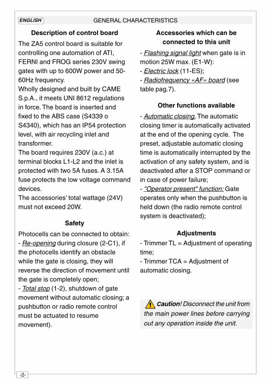
The ZA5 control board is suitable forcontrolling one automation of ATI,FERNI and FROG series 230V swinggates with up to 600W power and 50-60Hz frequency.Wholly designed and built by CAMES.p.A., it meets UNI 8612 regulationsin force. The board is inserted andfixed to the ABS case (S4339 oS4340), which has an IP54 protectionlevel, with air recycling inlet andtransformer.The board requires 230V (a.c.) atterminal blocks L1-L2 and the inlet isprotected with two 5A fuses. A 3.15Afuse protects the low voltage commanddevices.The accessories’ total wattage (24V)must not exceed 20W.
Safety
Photocells can be connected to obtain:- Re-opening during closure (2-C1), ifthe photocells identify an obstaclewhile the gate is closing, they willreverse the direction of movement untilthe gate is completely open;- Total stop (1-2), shutdown of gatemovement without automatic closing; apushbutton or radio remote controlmust be actuated to resumemovement).
Accessories which can beconnected to this unit
- Flashing signal light when gate is inmotion 25W max. (E1-W):- Electric lock (11-ES);- Radiofrequency «AF» board (seetable pag.7).
Other functions available
- Automatic closing. The automaticclosing timer is automatically activatedat the end of the opening cycle. Thepreset, adjustable automatic closingtime is automatically interrupted by theactivation of any safety system, and isdeactivated after a STOP command orin case of power failure;- "Operator present" function: Gateoperates only when the pushbutton isheld down (the radio remote controlsystem is deactivated);
Adjustments
- Trimmer TL = Adjustment of operatingtime;- Trimmer TCA = Adjustment ofautomatic closing.
Caution! Disconnect the unit from
the main power lines before carrying
out any operation inside the unit.
-3-
CARACTÉRISTIQUES GÉNÉRALESFRANÇAIS
Attention! Avant d’intervenir àl’intérieur de l’appareillage, couper latension de ligne.
Description carte de commande
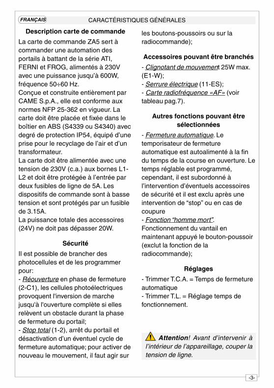
La carte de commande ZA5 sert àcommander une automation desportails à battant de la série ATI,FERNI et FROG, alimentés à 230Vavec une puissance jusqu’à 600W,fréquence 50÷60 Hz.Conçue et construite entièrement parCAME S.p.A., elle est conforme auxnormes NFP 25-362 en vigueur. Lacarte doit être placée et fixée dans leboîtier en ABS (S4339 ou S4340) avecdegré de protection IP54, équipé d’uneprise pour le recyclage de l’air et d’untransformateur.La carte doit être alimentée avec unetension de 230V (c.a.) aux bornes L1-L2 et doit être protégée à l’entrée pardeux fusibles de ligne de 5A. Lesdispositifs de commande sont à bassetension et sont protégés par un fusiblede 3.15A.La puissance totale des accessoires(24V) ne doit pas dépasser 20W.
Sécurité
Il est possible de brancher desphotocellules et de les programmerpour:- Réouverture en phase de fermeture(2-C1), les cellules photoélectriquesprovoquent l'inversion de marchejusqu'à l'ouverture complète si ellesrelèvent un obstacle durant la phasede fermeture du portail;- Stop total (1-2), arrêt du portail etdésactivation d’un éventuel cycle defermeture automatique; pour activer denouveau le mouvement, il faut agir sur
les boutons-poussoirs ou sur laradiocommande);
Accessoires pouvant être branchés
- Clignotant de mouvement 25W max.(E1-W);- Serrure électrique (11-ES);- Carte radiofréquence «AF» (voirtableau pag.7).
Autres fonctions pouvant êtresélectionnées
- Fermeture automatique. Letemporisateur de fermetureautomatique est autoalimenté à la findu temps de la course en ouverture. Letemps réglable est programmé,cependant, il est subordonné àl’intervention d’éventuels accessoiresde sécurité et il est exclu après uneintervention de “stop” ou en cas decoupure- Fonction “homme mort”.Fonctionnement du vantail enmaintenant appuyé le bouton-poussoir(exclut la fonction de laradiocommande);
Réglages
- Trimmer T.C.A. = Temps de fermetureautomatique- Trimmer T.L. = Réglage temps defonctionnement.
-4-
ALLGEMEINE MERKMALE
Achtung ! Das Gerät vorEingriffen im inneren spannungsfreischalten.
DEUTSCH
Beschreibung des Steuergeräts
Die Steuergeräts ZA5 ist für dieSteuerung von eins automatischFlügeltoren der Baureihe ATI, FERNIund FROG mit einer Versorgung von230V und einer Leistung bis zu 600W,Frequenz 50÷60 Hz, geeignet. Entwurfund Konstruktion sind von der CAMES.p.A.; sie entspricht den geltendenRichtlinien UNI 8612. Die Karte wirdeingeschoben und im ABS-Kasten(S4339 oder S4340) mit SchutzgradIP54 sowie Anschluß für dieLuftrückführung und Transformator,befestigt.Die Versorgung der Karte erfolgt durch230V-Sapnnung (a.c.) über dieKlemmen L1-L2 und ist am Eingangdurch 2 5A-Sicherungen geschützt. DieSteuervorrichtungen arbeiten mitUnterspannung und sind durch eine3.15A-Sicherung geschützt.Die Gesamtleistung des Zubehörs(24V) darf 20W nicht überschreiten.
Sicherheitsvorrichtungen
Die Lichtschranken können fürfolgende Funktionen angeschlossenbzw. vorbereitet werden:- Wiederöffnen beim Schließen (2-C1),die Lichtschranken ermitteln einHindernis während des schließensvom Tor und lösen die Umkehr derLaufrichtung vom Tor aus, bis dieseswieder vollständig geöffnet ist;- Totalstop (1-2), sofortiger Stillstand
des Tores mit Ausschluß eventuellerSchließautomatik: Fortsetzung desTorlaufs über Drucktaster- bzw.Funksendersteuerung;
Anschließbares Zubehör
- Blinkleuchte “Tor in Bewegung” 25Wmax. (E1-W);- Elektroschloß (11-ES);- Funkfrequenz-Platine «AF» (sieheTabelle Seite 7)
Andere Wahlfunktionen
- Schließautomatik. DerSchließautomatik-Zeischalter speistsich beim Öffnen am Ende derTorlaufzeit selbst . Die voreingestellteZeit ist auf jeden Fall immer demEingriff eventuellerSicherheitsvorrichtungenuntergeordnet und schließt sich nacheinem “Stop”-Eingriff bzw. beiStromausfall selbst aus;- Funktion “Bedienung vom Steuerpult”.Torbetrieb durch Drucktasterbetätigung(Funkfernsteuerung ausgeschlossen);
Einstellungen
- Trimmer TCA = ZeiteinstellungSchließautomatik;- Trimmer TL = Einstellung Laufzeit.
-5-
CARACTERISTICAS GENERALESESPANOL
¡Atención! Antes de actuar den-tro del aparato, quitar la tensión delínea.
Descripción tarjeta de mando
La tarjeta de mando ZA5 es adecuadapara el accionamiento de un automa-tizacion para puertas de batiente de laserie ATI, FERNI y FROG, alimentadasa 230V, con potencia de hasta 600W,frecuencia 50÷60 Hz.Diseñada y fabricada completamentepor CAME S.p.A., responde a lasnormas UNI 8612 vigentes. La tarjetase instala y fija en una caja de ABS(S4339 o S4340) con grado deprotección IP54, con toma pararecirculación de aire y transformador.La tarjeta se alimenta con tensión a230V (c.a.) en los bornes L1-L2 y estáprotegida en entrada con dos fusiblesde línea de 5A. Los dispositivos demando son de baja tensión y estánprotegidos con fusible de 3.15A.La potencia total de los accesorios(24V) no debe superar los 20W.
Seguridad
Las fotocélulas pueden estarconectadas y predispuestas para:- Reapertura en la fase de cierre (2-C1), las fotocélulas detectan unobstáculo durante el cierre de lapuerta, provocando la inversión demarcha hasta la apertura completa;- Parada total (1-2), parada de lapuerta excluyendo el posible ciclo decierre automático; para reactivar elmovimiento es preciso actuar en elteclado o en el mando a distancia);
Accesorios conectables
- Lámpara intermitente de movimiento25W max. (E1-W);- Cerradura eléctrica (11-ES);- Tarjeta radiofrecuencia «AF43» (vertabla pág. 7).
Otras funciones seleccionables
- Cierre automático. El temporizador decierre automático se autoalimenta enfin-de-tiempo carrera en fase deapertura. El tiempo prefijado regulable,sin embargo, está subordinado a laintervención de posibles accesorios deseguridad y se excluye después deuna intervención de parada o en casode falta de energía eléctrica;- Función a "hombre presente".Funcionamiento de la puertamanteniendo pulsada la tecla (excluyela función del mando a distancia);
Regulaciones
- Trimer TCA = Tiempo cierreautomático;- Trimer TL = Regulación tiempotrabajo.
-6-
��������������
������
��� ���
��
�������� �����������
���� �� ��
1 2
1 2 3 4L1 L2
COMPONENTI PRINCIPALI
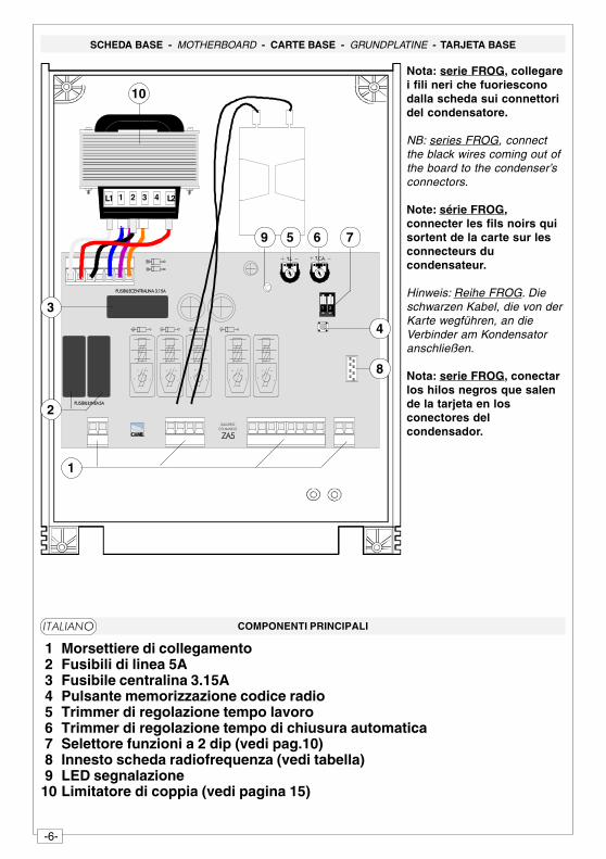
�1 Morsettiere di collegamento 2 Fusibili di linea 5A 3 Fusibile centralina 3.15A 4 Pulsante memorizzazione codice radio 5 Trimmer di regolazione tempo lavoro 6 Trimmer di regolazione tempo di chiusura automatica 7 Selettore funzioni a 2 dip (vedi pag.10) 8 Innesto scheda radiofrequenza (vedi tabella) 9 LED segnalazione10 Limitatore di coppia (vedi pagina 15)
SCHEDA BASE - MOTHERBOARD - CARTE BASE - GRUNDPLATINE - TARJETA BASE
Nota: serie FROG, collegarei fili neri che fuoriesconodalla scheda sui connettoridel condensatore.
NB: series FROG, connectthe black wires coming out ofthe board to the condenser’sconnectors.
Note: série FROG,connecter les fils noirs quisortent de la carte sur lesconnecteurs ducondensateur.
Hinweis: Reihe FROG. Dieschwarzen Kabel, die von derKarte wegführen, an dieVerbinder am Kondensatoranschließen.
Nota: serie FROG, conectarlos hilos negros que salende la tarjeta en losconectores delcondensador.
1
2
3
4
5 6 7
8
9
10
��������
-7-
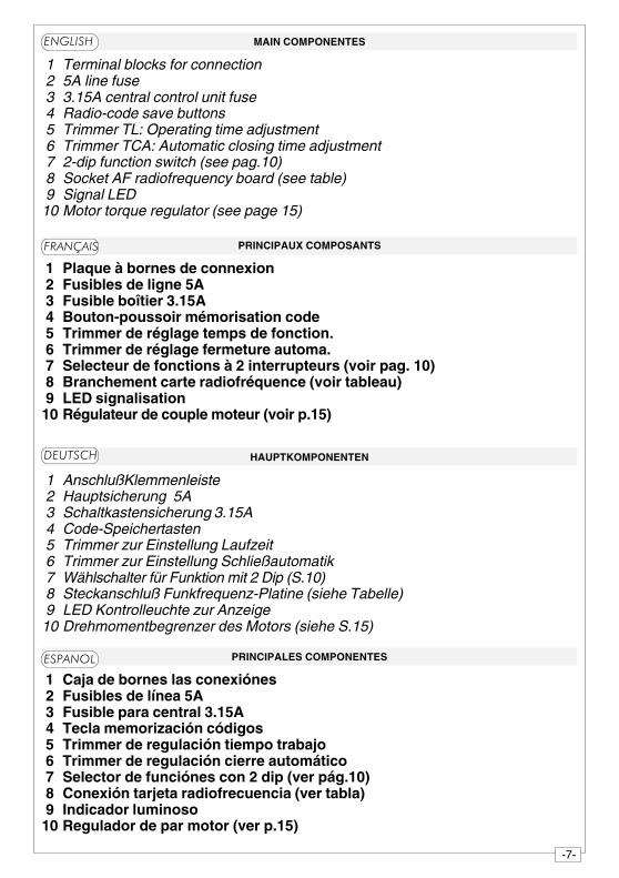
MAIN COMPONENTES
�1 Terminal blocks for connection 2 5A line fuse 3 3.15A central control unit fuse 4 Radio-code save buttons 5 Trimmer TL: Operating time adjustment 6 Trimmer TCA: Automatic closing time adjustment 7 2-dip function switch (see pag.10) 8 Socket AF radiofrequency board (see table) 9 Signal LED10 Motor torque regulator (see page 15)
HAUPTKOMPONENTEN
1 AnschlußKlemmenleiste 2 Hauptsicherung 5A 3 Schaltkastensicherung 3.15A 4 Code-Speichertasten 5 Trimmer zur Einstellung Laufzeit 6 Trimmer zur Einstellung Schließautomatik 7 Wählschalter für Funktion mit 2 Dip (S.10) 8 Steckanschluß Funkfrequenz-Platine (siehe Tabelle) 9 LED Kontrolleuchte zur Anzeige10 Drehmomentbegrenzer des Motors (siehe S.15)
PRINCIPAUX COMPOSANTS
1 Plaque à bornes de connexion 2 Fusibles de ligne 5A 3 Fusible boîtier 3.15A 4 Bouton-poussoir mémorisation code 5 Trimmer de réglage temps de fonction. 6 Trimmer de réglage fermeture automa. 7 Selecteur de fonctions à 2 interrupteurs (voir pag. 10) 8 Branchement carte radiofréquence (voir tableau) 9 LED signalisation10 Régulateur de couple moteur (voir p.15)
PRINCIPALES COMPONENTES
1 Caja de bornes las conexiónes 2 Fusibles de línea 5A 3 Fusible para central 3.15A 4 Tecla memorización códigos 5 Trimmer de regulación tiempo trabajo 6 Trimmer de regulación cierre automático 7 Selector de funciónes con 2 dip (ver pág.10) 8 Conexión tarjeta radiofrecuencia (ver tabla) 9 Indicador luminoso10 Regulador de par motor (ver p.15)
�����
���� ��
�����
������
-8-
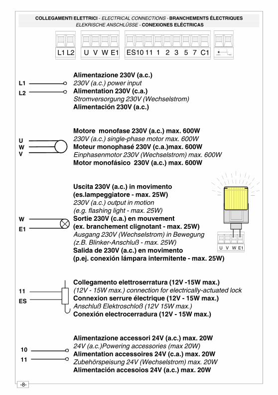
COLLEGAMENTI ELETTRICI - ELECTRICAL CONNECTIONS - BRANCHEMENTS ÉLECTRIQUES ELEKRISCHE ANSCHLÜSSE - CONEXIONES ELÉCTRICAS
Alimentazione 230V (a.c.)230V (a.c.) power inputAlimentation 230V (c.a.)Stromversorgung 230V (Wechselstrom)Alimentación 230V (a.c.)
Motore monofase 230V (a.c.) max. 600W230V (a.c.) single-phase motor max. 600WMoteur monophasé 230V (c.a.)max. 600WEinphasenmotor 230V (Wechselstrom) max. 600WMotor monofásico 230V (a.c.) max. 600W
Uscita 230V (a.c.) in movimento(es.lampeggiatore - max. 25W)230V (a.c.) output in motion(e.g. flashing light - max. 25W)Sortie 230V (c.a.) en mouvement(ex. branchement clignotant - max. 25W)Ausgang 230V (Wechselstrom) in Bewegung(z.B. Blinker-Anschluß - max. 25W)Salida de 230V (a.c.) en movimento(p.ej. conexión lámpara intermitente - max. 25W)
Collegamento elettroserratura (12V -15W max.)(12V - 15W max.) connection for electrically-actuated lockConnexion serrure électrique (12V - 15W max.)Anschluß Elektroschloß (12V 15W max.)Conexión electrocerradura (12V - 15W max.)
Alimentazione accessori 24V (a.c.) max. 20W24V (a.c.)Powering accessories (max 20W)Alimentation accessoires 24V (c.a.) max. 20WZubehörspeisung 24V (Wechselstrom) max. 20WAlimentación accesoios 24V (a.c.) max. 20W
U V W E1
10
11
W
E1
L1
L2
UWV
L1 L2 U V W E1 ES10 11 3 5 71 2 C1
11
ES
-9-
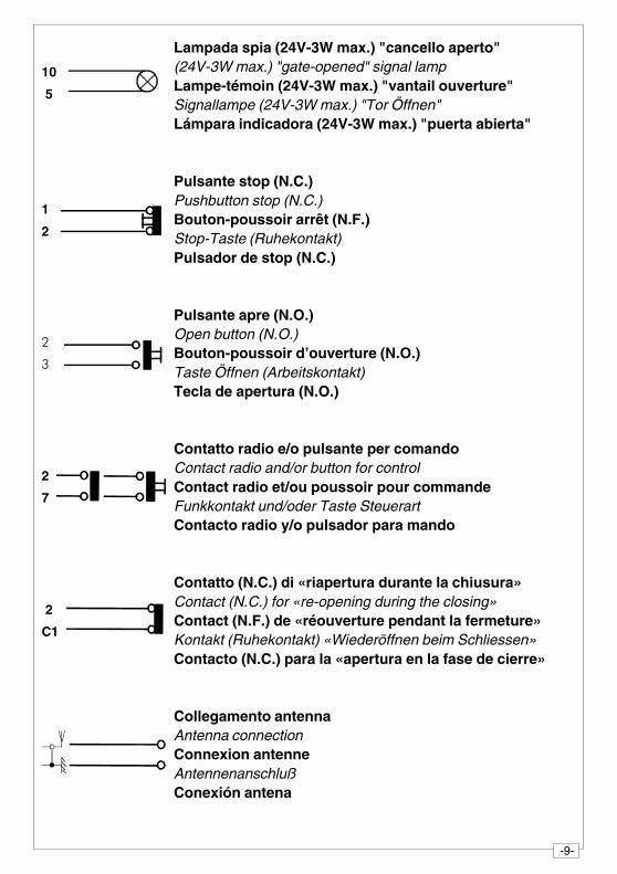
Lampada spia (24V-3W max.) "cancello aperto"(24V-3W max.) "gate-opened" signal lampLampe-témoin (24V-3W max.) "vantail ouverture"Signallampe (24V-3W max.) "Tor Öffnen"Lámpara indicadora (24V-3W max.) "puerta abierta"
Pulsante stop (N.C.)Pushbutton stop (N.C.)Bouton-poussoir arrêt (N.F.)Stop-Taste (Ruhekontakt)Pulsador de stop (N.C.)
Pulsante apre (N.O.)Open button (N.O.)Bouton-poussoir d’ouverture (N.O.)Taste Öffnen (Arbeitskontakt)Tecla de apertura (N.O.)
Contatto radio e/o pulsante per comandoContact radio and/or button for controlContact radio et/ou poussoir pour commandeFunkkontakt und/oder Taste SteuerartContacto radio y/o pulsador para mando
Contatto (N.C.) di «riapertura durante la chiusura»Contact (N.C.) for «re-opening during the closing»Contact (N.F.) de «réouverture pendant la fermeture»Kontakt (Ruhekontakt) «Wiederöffnen beim Schliessen»Contacto (N.C.) para la «apertura en la fase de cierre»
Collegamento antennaAntenna connectionConnexion antenneAntennenanschlußConexión antena
10
5
1
2
2
7
2
C1
�
�
-10-
AF
43S
/SM
��������������
������
��� ���
��
�������� ��������
���� �� ��
1 2
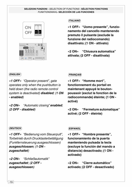
SELEZIONI FUNZIONI - SELECTION OF FUNCTIONS - SÉLECTION FONCTIONSFUNKTIONSWAHL- SELECCIÓN DE LAS FUNCIONES
ITALIANO
ENGLISH FRANÇAIS
��
���
DEUTSCH ESPANOL
«1 OFF» “Uomo presente”, funzio-namento del cancello mantenendopremuto il pulsante (esclude lafunzione del radiocomando)disattivato; (1 ON - attivato)
«2 ON» “Chiusura automatica”attivata; (2 OFF - disattivata)
«1 OFF» “Operator present”, gateoperates only when the pushbutton isheld down (the radio remote controlsystem is deactivated) disabled; (1 ON- enabled)
«2 ON» “Automatic closing” enabled;(2 OFF - disabled)
«1 OFF» “Homme mort”,fonctionnement du portail enmaintenant appuyé le bouton-poussoir (exclut la fonction de laradiocommande) éteinte; (1 ON -activé)
«2 ON» “Fermeture automatique”activé; (2 OFF - éteinte)
«1 OFF» “Bedienung vom Steuerpult”,Torbetrieb durch Drucktasterbetätigung(Funkfernsteuerung ausgeschlossen)ausgeschlossen; (1 ON -zugeschaltet)
«2 ON» “Schließautomatik”zugeschaltet; (2 OFF -ausgeschlossen)
«1 OFF» “Hombre presente”,funcionamiento de la puertamanteniendo pulsada la tecla(excluye la función del mando adistancia) desactivado; (1 ON -activado)
«2 ON» “Cierre automático”activado; (2 OFF - desactivado)
1 2
-11-
AF
43S
/SM
��������������
������
��� ���
��
�������� ��������
���� �� ��
1 2
������������ ���
���������������
����������� ���
������ �������
�������������� ���
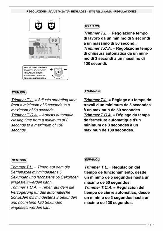
Trimmer T.L. = Regolazione tempodi lavoro da un minimo di 5 secondia un massimo di 50 secondi.Trimmer T.C.A. = Regolazione tempodi chiusura automatica da un mini-mo di 3 secondi a un massimo di130 secondi.
Trimmer T.L. = Réglage du temps detravail d'un minimum de 5 secondesà un maximun de 50 secondes.Trimmer T.C.A. = Réglage du tempsde fermeture automatique d'unminimum de 3 secondes à unmaximun de 130 secondes.
Trimmer T.L. = Regulación deltiempo de funcionamiento, desdeun mínimo de 5 segundos hasta unmáximo de 50 segundos.Trimmer T.C.A. = Regulación deltiempo de cierre automático, desdeun mínimo de 3 segundos hasta unmáximo de 130 segundos.
Trimmer T.L. = Adjusts operating timefrom a minimum of 5 seconds to amaximum of 50 seconds.Trimmer T.C.A. = Adjusts automaticclosing time from a minimum of 3seconds to a maximum of 130seconds.
Trimmer T.L. = Timer, auf dem dieBetriebszeit mit mindestens 5Sekunden und höchstens 50 Sekundeneingestellt werden kann.Trimmer T.C.A. = Timer, auf dem dieVerzögerung für das automatischeSchließen mit mindestens 3 Sekundenund höchstens 130 Sekundeneingestellt werden kann.
REGOLAZIONI - ADJUSTMENTS - RÉGLAGES - EINSTELLUNGEN - REGULACIONES
ITALIANO
FRANÇAIS
ESPANOL
ENGLISH
DEUTSCH
���� �� ��
-12-
1 2 3 4
1 2 3 4
��� ��� �� � �� ��
��������������
���� ��
�� ��� �
��
�������� ��������
��� � �� ��
1 2
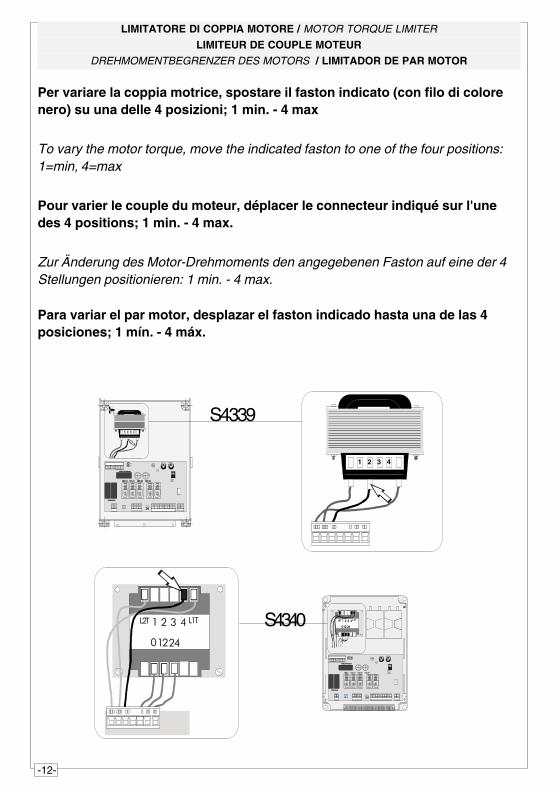
S4339
� � � ���� ���
� ����� � � ���� ���
� ����
��� ��� �� � �� ��
��������������
������
������
��
�������� ��������
��� � � � ��
1 2
S4340
LIMITATORE DI COPPIA MOTORE / MOTOR TORQUE LIMITER
LIMITEUR DE COUPLE MOTEUR
DREHMOMENTBEGRENZER DES MOTORS / LIMITADOR DE PAR MOTOR
Para variar el par motor, desplazar el faston indicado hasta una de las 4posiciones; 1 mín. - 4 máx.
Per variare la coppia motrice, spostare il faston indicato (con filo di colorenero) su una delle 4 posizioni; 1 min. - 4 max
To vary the motor torque, move the indicated faston to one of the four positions:1=min, 4=max
Pour varier le couple du moteur, déplacer le connecteur indiqué sur l'unedes 4 positions; 1 min. - 4 max.
Zur Änderung des Motor-Drehmoments den angegebenen Faston auf eine der 4Stellungen positionieren: 1 min. - 4 max.
-13-
PAGINA LASCIATA INTENZIONALMENTE BIANCA
THIS PAGE LEFT INTENTIONALLY BLANK
DIE SEITE WURDE ABSICHLICH LEER GELASSEN
NOUS AVONS LAISSÉ EXPRÈS CETTE PAGE BLANCHE
PÁGINA DEJADA EN BLANCO INTENCIONALMENTE
-14-
ENGLISH
PROCEDURE
A. insert an
AF card **.
B. encodetransmitter/s.
C. store code inthemotherboard.
FRANÇAIS
PROCEDURE
A. placer unecarte AF **.
B. codifier le/sémetteur/s.
C. mémoriser lacodificationsur la cartebase.
DEUTSCH
PROZEDUR
A. Stecken Sieeine Karte
AF **.
B. Codieren Sieden/dieSender.
C. Speichern Siedie Codierungauf derGrundplatine.
ITALIANO
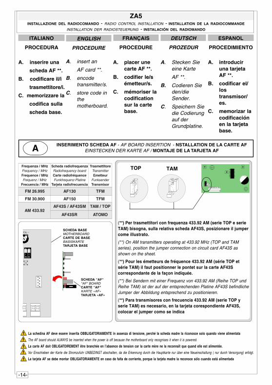
PROCEDURA
A. inserire una
scheda AF **.
B. codificare il/i
trasmettitore/i.
C. memorizzare la
codifica sulla
scheda base.
ZA5INSTALLAZIONE DEL RADIOCOMANDO - RADIO CONTROL INSTALLATION - INSTALLATION DE LA RADIOCOMMANDE
INSTALLATION DER RADIOSTEUERUNG - INSTALACIÓN DEL RADIOMANDO
ESPANOL
PROCEDIMIENTO
A. introduciruna tarjetaAF **.
B. codificar el/lostransmisor/es.
C. memorizar lacodificaciónen la tarjetabase.
(**) Per trasmettitori con frequenza 433.92 AM (serie TOP e serieTAM) bisogna, sulla relativa scheda AF43S, posizionare il jumpercome illustrato.
(**) On AM transmitters operating at 433.92 MHz (TOP and TAMseries), position the jumper connection on circuit card AF43S asshown on the sheet.
(**) Pour les émetteurs de fréquence 433.92 AM (série TOP etsérie TAM) il faut positionner le pontet sur la carte AF43Scorrespondante de la façon indiquée.
(**) Bei Sendern mit einer Frequenz von 433.92 AM (Reihe TOP undReihe TAM) ist der auf der entsprechenden Platine AF43S befindlicheJumper der Abbildung entsprechend zu positionieren.
(**) Para transmisores con frecuencia 433.92 AM (serie TOP yserie TAM) es necesario, en la tarjeta corespondiente AF43S,colocar el jumper como se indica
TOP TAM
La schedina AF deve essere inserita OBBLIGATORIAMENTE in assenza di tensione, perché la scheda madre la riconosce solo quando viene alimentata
The AF board should ALWAYS be inserted when the power is off because the motherboard only recognises it when it is powered.
La carte AF doit OBLIGATOIREMENT être branchée en l’absence de tension car la carte mère ne la reconnaît que quand elle est alimentée.
Vor Einschieben der Karte die Stromzufuhr UNBEDINGT abschalten, da die Erkennung durch die Hauptkarte nur über eine Neueinschaltung ( nur durch Versorgung) erfolgt.
La tarjeta AF se debe montar OBLIGATORIAMENTE en caso de falta de corriente, porque la tarjeta madre la reconoce sólo cuando está alimentada
zHM/azneuqerFzHM/ycneuqerFzHM/ecneuqerF
zHM/zneuqerFzHM/aicneucerF
azneuqerfoidaradehcSdraobycneuqerfoidaRecneuqérfoidaretraC
enitalP-zneuqerfknuFaicneucerfoidaratejraT
erotittemsarTrettimsnarT
ruettemErednesknuFrosimsnarT
599.62MF 031FA MFT
009.03MF 051FA MFT
29.334MAMS34FA/S34FA POT/MAT
RS34FA OMOTA
INSERIMENTO SCHEDA AF - AF BOARD INSERTION - NSTALLATION DE LA CARTE AFEINSTECKEN DER KARTE AF / MONTAJE DE LA TARJETA AFA
SCHEDA BASEMOTHERBOARDCARTE DE BASEBASISKARTETARJETA BASE
SCHEDA "AF""AF" BOARDCARTE "AF"KARTE «AF»TARJETA «AF»
�� ��
1 2
-15-
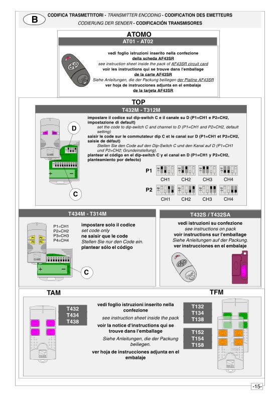
AT01 - AT02
vedi foglio istruzioni inserito nella confezionedella scheda AF43SR
see instruction sheet inside the pack of AF43SR circuit cardvoir les instructions qui se trouve dans l'emballage
de la carte AF43SRSiehe Anleitungen, die der Packung beiliegen der Platine AF43SR
ver hoja de instrucciones adjunta en el embalajede la tarjeta AF43SR
ATOMO
CODIFICA TRASMETTITORI - TRANSMITTER ENCODING - CODIFICATION DES EMETTEURS
CODIERUNG DER SENDER - CODIFICACIÓN TRANSMISORESB
vedi istruzioni su confezionesee instructions on pack
voir instructions sur l'emballageSiehe Anleitungen auf der Packung.ver instrucciones en el embalaje
T432S / T432SAT434M - T314M
impostare solo il codiceset code onlyne saisir que le codeStellen Sie nur den Code ein.plantear sólo el código
P1=CH1P2=CH2P3=CH3P4=CH4
1 2 3 4 5 6 7 8 9 10
C
P1 P2
P3 P4
TOP
impostare il codice sul dip-switch C e il canale su D (P1=CH1 e P2=CH2,impostazione di default)
set the code to dip-switch C and channel to D (P1=CH1 and P2=CH2, defaultsetting)
saisir le code sur le commutateur dip C et le canal sur D (P1=CH1 et P2=CH2,saisie de défaut)
Stellen Sie den Code auf den Dip-Switch C und den Kanal auf D (P1=CH1und P2=CH2; Grundeinstellung).
plantear el código en el dip-switch C y el canal en D (P1=CH1 y P2=CH2,planteamiento por defecto)
T432M - T312M
1 2 3 4 5 6 7 8 9 10
1 2 3 4
C
DP1 P2
P2
CH1 CH2 CH3 CH4
P1
CH1 CH2 CH3 CH41 2 3 4 1 2 3 4 1 2 3 41 2 3 4
1 2 3 4 1 2 3 4 1 2 3 4 1 2 3 4
vedi foglio istruzioni inserito nellaconfezione
see instruction sheet inside the pack
voir la notice d'instructions qui setrouve dans l'emballage
Siehe Anleitungen, die der Packungbeiliegen.
ver hoja de instrucciones adjunta en elembalaje
TAM
T132T134T138
T152T154T158
T432T434T438
TFM
-16-
CAME LOMBARDIA S.R.L.___COLOGNO M. (MI)(+39) 02 26708293 (+39) 02 25490288
CAME SUD S.R.L. _________________NAPOLI(+39) 081 752445 (+39) 081 7529109
CAME (AMERICA) L.L.C._________MIAMI (FL)(+1) 305 5930227 (+1) 305 5939823
CAME AUTOMATISMOS S.A_________MADRID(+34) 091 5285009 (+34) 091 4685442
CAME BELGIUM____________LESSINES(+32) 068 333014 (+32) 068 338019
CAME CANCELLI AUTOMATICI S.P.A.DOSSON DI CASIER (TREVISO)
(+39) 0422 (+39) 0422 490944
CANCELLI AUTOMATICI
CAME FRANCE S.A.___NANTERRE CEDEX (PARIS)(+33) 01 46130505 (+33) 01 46130500
CAME GMBH____KORNTAL BEI (STUTTGART)(+49) 07 11839590 (+49) 07 118395925
CAME GMBH________SEEFELD BEI (BERLIN)(+49) 03 33988390 (+49) 03 339885508
CAME PL SP.ZO.O_________WARSZAWA(+48) 022 8699933 (+48) 022 6399933
CAME UNITED KINGDOM LTD___NOTTINGHAM(+44) 01159 387200 (+44) 01159 382694
ASSISTENZA TECNICA
NUMERO VERDE
800 295830
WEBwww.came.it
SISTEMA QUALITÀCERTIFICATO
ITALIANO
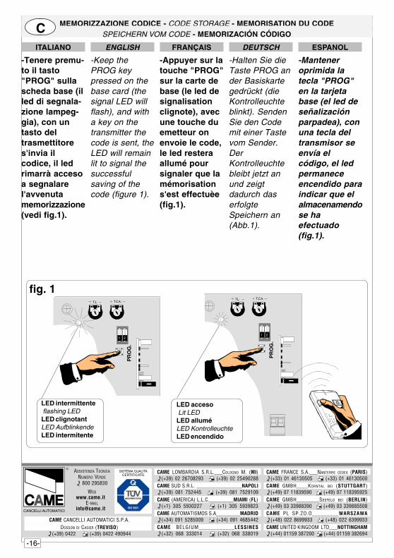
-Tenere premu-to il tasto"PROG" sullascheda base (illed di segnala-zione lampeg-gia), con untasto deltrasmettitores'invia ilcodice, il ledrimarrà accesoa segnalarel'avvenutamemorizzazione(vedi fig.1).
DEUTSCH
-Halten Sie dieTaste PROG ander Basiskartegedrückt (dieKontrolleuchteblinkt). SendenSie den Codemit einer Tastevom Sender.DerKontrolleuchtebleibt jetzt anund zeigtdadurch daserfolgteSpeichern an(Abb.1).
ESPANOL
-Manteneroprimida latecla "PROG"en la tarjetabase (el led deseñalizaciónparpadea), conuna tecla deltransmisor seenvía elcódigo, el ledpermaneceencendido paraindicar que elalmacenamendose haefectuado(fig.1).
ENGLISH
-Keep thePROG keypressed on thebase card (thesignal LED willflash), and witha key on thetransmitter thecode is sent, theLED will remainlit to signal thesuccessfulsaving of thecode (figure 1).
FRANÇAIS
-Appuyer sur latouche "PROG"sur la carte debase (le led designalisationclignote), avecune touche duemetteur onenvoie le code,le led resteraallumé poursignaler que lamémorisations'est effectuèe(fig.1).
MEMORIZZAZIONE CODICE - CODE STORAGE - MEMORISATION DU CODESPEICHERN VOM CODE - MEMORIZACIÓN CÓDIGOC
LED acceso Lit LEDLED alluméLED KontrolleuchteLED encendido
LED intermittente flashing LEDLED clignotantLED AufblinkendeLED intermitente
fig. 1���� �� ��
1 2
PR
OG
.
���� �� ��
1 2
PR
OG
.