Yamaha Brochure · 2020. 2. 11. · Title: Yamaha Brochure Created Date: 4/12/2017 8:18:47 PM
8/12/2019 Yamaha Tenere XT660Z Service Manual
http://slidepdf.com/reader/full/yamaha-tenere-xt660z-service-manual 1/398
SERVICE MANUAL
2008
XT660Z
8/12/2019 Yamaha Tenere XT660Z Service Manual
http://slidepdf.com/reader/full/yamaha-tenere-xt660z-service-manual 2/398
8/12/2019 Yamaha Tenere XT660Z Service Manual
http://slidepdf.com/reader/full/yamaha-tenere-xt660z-service-manual 3/398
EAS00020
NOTICEThis manual was produced by the Yamaha Motor Italia S.p.A.primarily for use by Yamaha dealers andtheir qualified mechanics. It is not possible to include all the knowledge of a mechanic in one manu-al. Therefore, anyone who uses this book to perform maintenance and repairs on Yamaha vehiclesshould have a basic understanding of mechanics and the techniques to repair these types of vehi-cles. Repair and maintenance work attempted by anyone without this knowledge is likely to renderthe vehicle unsafe and unfit for use.
Yamaha Motor Italia S.p.A. is continually striving to improve all of its models. Modifications and sig-nificant changes in specifications or procedures will be forwarded to all authorized Yamaha dealersand will appear in future editions of this manual where applicable.
NOTE:
Designs and specifications are subject to change without notice.
EAS00040
IMPORTANT MANUAL INFORMATION
Particularly important information is distinguished in this manual by the following.
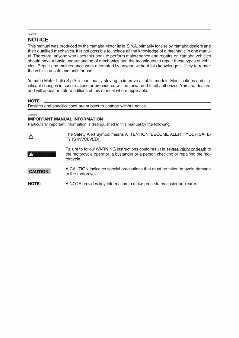
The Safety Alert Symbol means ATTENTION! BECOME ALERT! YOUR SAFE-TY IS INVOLVED!
Failure to follow WARNING instructions could result in severe injury or death tothe motorcycle operator, a bystander or a person checking or repairing the mo-torcycle.
A CAUTION indicates special precautions that must be taken to avoid damageto the motorcycle.
WARNING
CAUTION:
8/12/2019 Yamaha Tenere XT660Z Service Manual
http://slidepdf.com/reader/full/yamaha-tenere-xt660z-service-manual 4/398
EAS20090
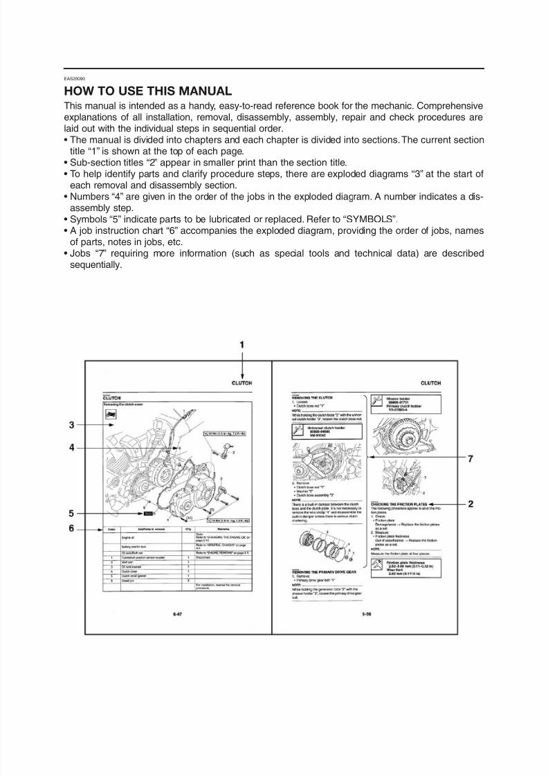
HOW TO USE THIS MANUALThis manual is intended as a handy, easy-to-read reference book for the mechanic. Comprehensiveexplanations of all installation, removal, disassembly, assembly, repair and check procedures arelaid out with the individual steps in sequential order.• The manual is divided into chapters and each chapter is divided into sections.The current section
title “1” is shown at the top of each page.• Sub-section titles “2” appear in smaller print than the section title.• To help identify parts and clarify procedure steps, there are exploded diagrams “3” at the start of
each removal and disassembly section.• Numbers “4” are given in the order of the jobs in the exploded diagram. A number indicates a dis-
assembly step.• Symbols “5” indicate parts to be lubricated or replaced. Refer to “SYMBOLS”.• A job instruction chart “6” accompanies the exploded diagram, providing the order of jobs, names
of parts, notes in jobs, etc.• Jobs “7” requiring more information (such as special tools and technical data) are described
sequentially.
8/12/2019 Yamaha Tenere XT660Z Service Manual
http://slidepdf.com/reader/full/yamaha-tenere-xt660z-service-manual 5/398
EAS20100
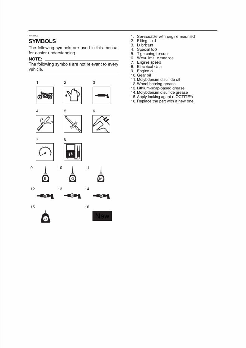
SYMBOLSThe following symbols are used in this manualfor easier understanding.
NOTE:
The following symbols are not relevant to everyvehicle.
1. Serviceable with engine mounted
2. Filling fluid3. Lubricant4. Special tool5. Tightening torque6. Wear limit, clearance7. Engine speed8. Electrical data9. Engine oil10.Gear oil11. Molybdenum disulfide oil
12. Wheel bearing grease13. Lithium-soap-based grease14. Molybdenum disulfide grease15. Apply locking agent (LOCTITE ® )16. Replace the part with a new one.
1 2 3
4 5
7 8
6
9 1110
8/12/2019 Yamaha Tenere XT660Z Service Manual
http://slidepdf.com/reader/full/yamaha-tenere-xt660z-service-manual 6/398
GENERAL INFORMATION
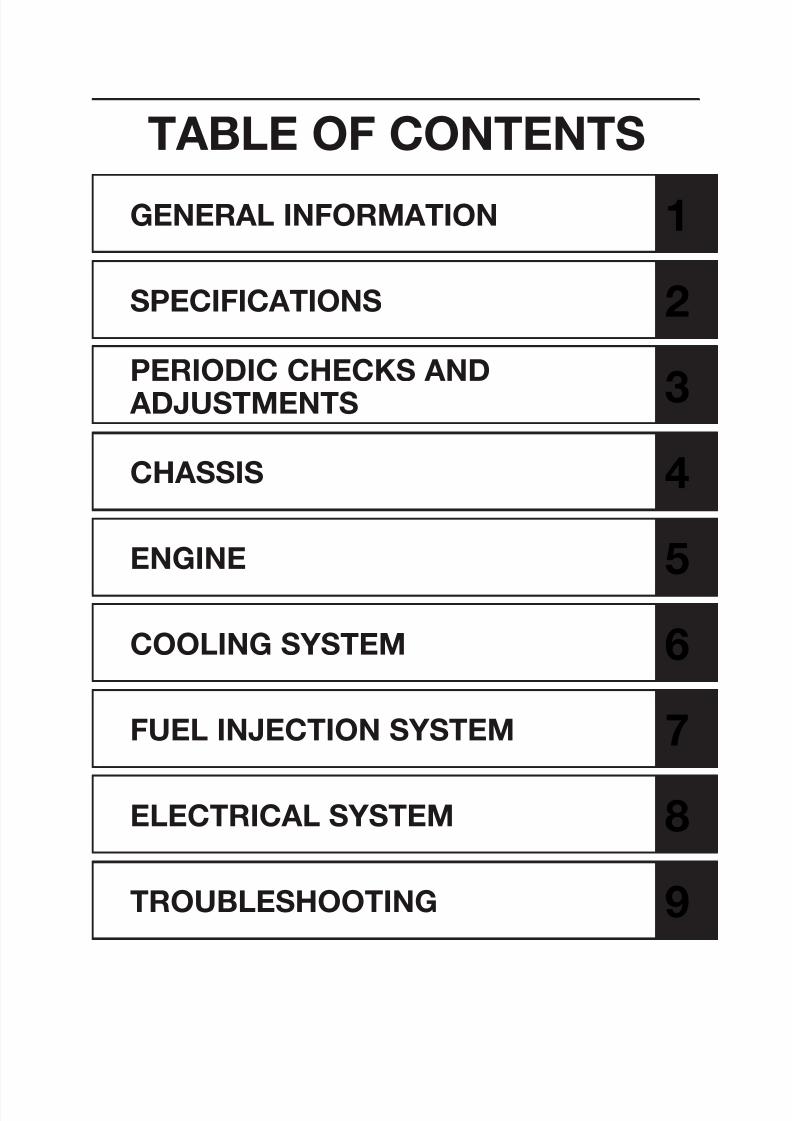
TABLE OF CONTENTS
1
SPECIFICATIONS 2
PERIODIC CHECKS AND
ADJUSTMENTS3
CHASSIS 4
ENGINE 5
8/12/2019 Yamaha Tenere XT660Z Service Manual
http://slidepdf.com/reader/full/yamaha-tenere-xt660z-service-manual 7/398
GENERAL INFORMATION
IDENTIFICATION............................................................................................ 1-1VEHICLE IDENTIFICATION NUMBER..................................................... 1-1MODEL LABEL......................................................................................... 1-1
FEATURES ..................................................................................................... 1-2OUTLINE OF THE FI SYSTEM................................................................ 1-2
FI SYSTEM............................................................................................... 1-3INSTRUMENT FUNCTIONS .................................................................... 1-4
IMPORTANT INFORMATION ........................................................................ 1-7PREPARATION FOR REMOVAL AND DISASSEMBLY ........................... 1-7REPLACEMENT PARTS .......................................................................... 1-7GASKETS, OIL SEALS AND O-RINGS................................................... 1-7LOCK WASHERS/PLATES AND COTTER PINS..................................... 1-7
BEARINGS AND OIL SEALS................................................................... 1-8CIRCLIPS ................................................................................................. 1-8
CHECKING THE CONNECTIONS ................................................................ 1-9
SPECIAL TOOLS ...........................................................................................1-10
1

8/12/2019 Yamaha Tenere XT660Z Service Manual
http://slidepdf.com/reader/full/yamaha-tenere-xt660z-service-manual 8/398
8/12/2019 Yamaha Tenere XT660Z Service Manual
http://slidepdf.com/reader/full/yamaha-tenere-xt660z-service-manual 9/398
IDENTIFICATION
1
IDENTIFICATION
EAS00170
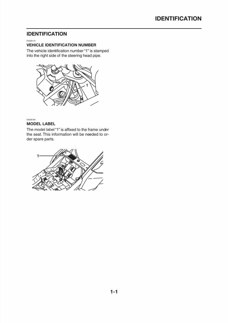
VEHICLE IDENTIFICATION NUMBER
The vehicle identification number “1” is stampedinto the right side of the steering head pipe.
EAS00180
MODEL LABEL
The model label “1” is affixed to the frame underthe seat. This information will be needed to or-der spare parts.
8/12/2019 Yamaha Tenere XT660Z Service Manual
http://slidepdf.com/reader/full/yamaha-tenere-xt660z-service-manual 10/398
FEATURES
EAS00019
FEATURESEAS00896
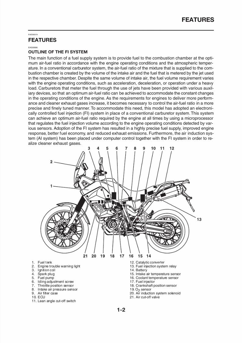
OUTLINE OF THE FI SYSTEM
The main function of a fuel supply system is to provide fuel to the combustion chamber at the opti-mum air-fuel ratio in accordance with the engine operating conditions and the atmospheric temper-ature. In a conventional carburetor system, the air-fuel ratio of the mixture that is supplied to the com-bustion chamber is created by the volume of the intake air and the fuel that is metered by the jet usedin the respective chamber. Despite the same volume of intake air, the fuel volume requirement varies
with the engine operating conditions, such as acceleration, deceleration, or operation under a heavyload. Carburetors that meter the fuel through the use of jets have been provided with various auxil-iary devices, so that an optimum air-fuel ratio can be achieved to accommodate the constant changesin the operating conditions of the engine. As the requirements for engines to deliver more perform-ance and cleaner exhaust gases increase, it becomes necessary to control the air-fuel ratio in a moreprecise and finely tuned manner.To accommodate this need, this model has adopted an electroni-cally controlled fuel injection (FI) system in place of a conventional carburetor system.This systemcan achieve an optimum air-fuel ratio required by the engine at all times by using a microprocessorthat regulates the fuel injection volume according to the engine operating conditions detected by var-
ious sensors. Adoption of the FI system has resulted in a highly precise fuel supply, improved engineresponse, better fuel economy, and reduced exhaust emissions. Furthermore, the air induction sys-tem (AI system) has been placed under computer control together with the FI system in order to re-alize cleaner exhaust gases.
8/12/2019 Yamaha Tenere XT660Z Service Manual
http://slidepdf.com/reader/full/yamaha-tenere-xt660z-service-manual 11/398
FEATURES
EAS00897
FI SYSTEM
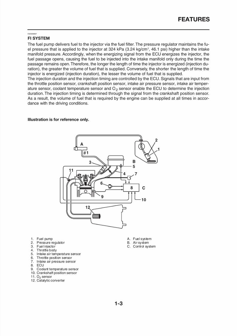
The fuel pump delivers fuel to the injector via the fuel filter.The pressure regulator maintains the fu-el pressure that is applied to the injector at 324 kPa (3.24 kg/cm2, 46.1 psi) higher than the intakemanifold pressure. Accordingly, when the energizing signal from the ECU energizes the injector, thefuel passage opens, causing the fuel to be injected into the intake manifold only during the time thepassage remains open.Therefore, the longer the length of time the injector is energized (injection du-ration), the greater the volume of fuel that is supplied. Conversely, the shorter the length of time theinjector is energized (injection duration), the lesser the volume of fuel that is supplied.The injection duration and the injection timing are controlled by the ECU. Signals that are input from
the throttle position sensor, crankshaft position sensor, intake air pressure sensor, intake air temper-ature sensor, coolant temperature sensor and O2 sensor enable the ECU to determine the injectionduration. The injection timing is determined through the signal from the crankshaft position sensor.As a result, the volume of fuel that is required by the engine can be supplied at all times in accor-dance with the driving conditions.
Illustration is for reference only.
8/12/2019 Yamaha Tenere XT660Z Service Manual
http://slidepdf.com/reader/full/yamaha-tenere-xt660z-service-manual 12/398
FEATURES
INSTRUMENT FUNCTIONS
EAUB1500
Multi-function display
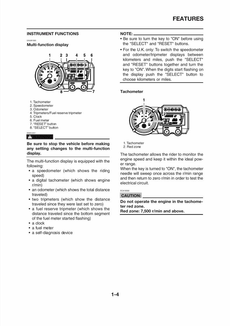
1. Tachometer2. Speedometer3. Odometer4. Tripmeters/Fuel reserve tripmeter5. Clock
6. Fuel meter7. “RESET” button8. “SELECT” button
EWA12311
WARNING
Be sure to stop the vehicle before making
any setting changes to the multi-function
display.
The multi-function display is equipped with thefollowing:• a speedometer (which shows the riding
NOTE:
• Be sure to turn the key to "ON" before usingthe "SELECT" and "RESET" buttons.
• For the U.K. only: To switch the speedometer
and odometer/tripmeter displays between
kilometers and miles, push the "SELECT"
and "RESET" buttons together and turn the
key to "ON".When the digits start flashing on
the display push the "SELECT" button to
choose kilometers or miles.
Tachometer
1. Tachometer2. Red zone
The tachometer allows the rider to monitor the
engine speed and keep it within the ideal pow-er range.When the key is turned to "ON", the tachometerneedle will sweep once across the r/min range
8/12/2019 Yamaha Tenere XT660Z Service Manual
http://slidepdf.com/reader/full/yamaha-tenere-xt660z-service-manual 13/398
FEATURES
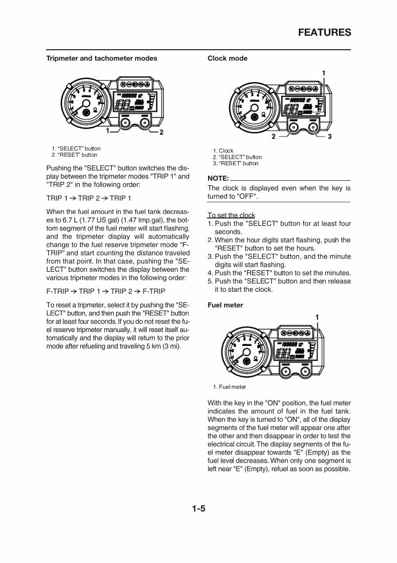
Tripmeter and tachometer modes
1. “SELECT” button2. “RESET” button
Pushing the "SELECT" button switches the dis-play between the tripmeter modes "TRIP 1" and"TRIP 2" in the following order:
TRIP 16 TRIP 26 TRIP 1
When the fuel amount in the fuel tank decreas-es to 6.7 L (1.77 US gal) (1.47 Imp.gal), the bot-tom segment of the fuel meter will start flashing,and the tripmeter display will automaticallychange to the fuel reserve tripmeter mode “F-TRIP” and start counting the distance traveledfrom that point. In that case, pushing the "SE-LECT" button switches the display between the
various tripmeter modes in the following order:
F-TRIP6 TRIP 16 TRIP 26 F-TRIP
Clock mode
1. Clock2. “SELECT” button3. “RESET” button
NOTE:
The clock is displayed even when the key isturned to "OFF".
To set the clock1. Push the "SELECT" button for at least four
seconds.2. When the hour digits start flashing, push the
"RESET" button to set the hours.3. Push the "SELECT" button, and the minute
digits will start flashing.4. Push the "RESET" button to set the minutes.5. Push the "SELECT" button and then release
it to start the clock.
8/12/2019 Yamaha Tenere XT660Z Service Manual
http://slidepdf.com/reader/full/yamaha-tenere-xt660z-service-manual 14/398
FEATURES
NOTE:
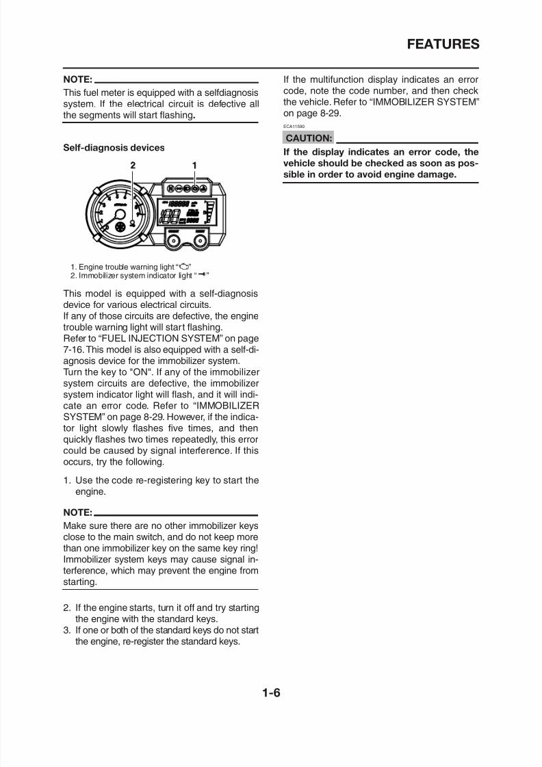
This fuel meter is equipped with a selfdiagnosissystem. If the electrical circuit is defective allthe segments will start flashing.
Self-diagnosis devices
1. Engine trouble warning light “U”2. Immobilizer system indicator light “ ”
This model is equipped with a self-diagnosisdevice for various electrical circuits.If any of those circuits are defective, the enginetrouble warning light will start flashing.Refer to “FUEL INJECTION SYSTEM” on page7-16.This model is also equipped with a self-di-agnosis device for the immobilizer system.Turn the key to "ON". If any of the immobilizersystem circuits are defective, the immobilizersystem indicator light will flash, and it will indi-cate an error code Refer to “IMMOBILIZER
If the multifunction display indicates an error
code, note the code number, and then checkthe vehicle. Refer to “IMMOBILIZER SYSTEM”on page 8-29.
ECA11590
CAUTION:
If the display indicates an error code, the
vehicle should be checked as soon as pos-
sible in order to avoid engine damage.
8/12/2019 Yamaha Tenere XT660Z Service Manual
http://slidepdf.com/reader/full/yamaha-tenere-xt660z-service-manual 15/398
IMPORTANT INFORMATION
EAS20180
IMPORTANT INFORMATIONEAS20190
PREPARATION FOR REMOVAL AND
DISASSEMBLY
1. Before removal and disassembly, remove alldirt, mud, dust and foreign material.
2. Use only the proper tools and cleaningequipment.Refer to “SPECIAL TOOLS” on page 1-10.
3. When disassembling, always keep matedparts together. This includes gears, cylin-ders,pistons and other parts that have been“mated” through normal wear. Mated partsmust always be reused or replaced as an
assembly.
EAS20210
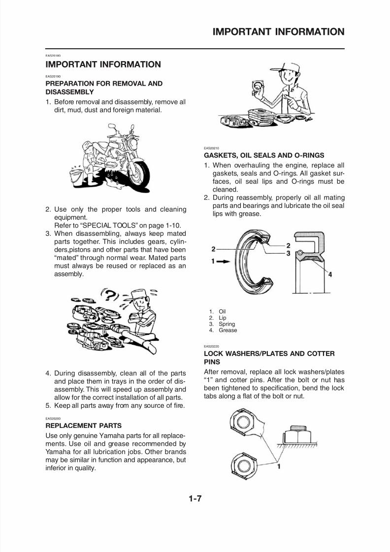
GASKETS, OIL SEALS AND O-RINGS
1. When overhauling the engine, replace allgaskets, seals and O-rings. All gasket sur-faces, oil seal lips and O-rings must becleaned.
2. During reassembly, properly oil all mating
parts and bearings and lubricate the oil seallips with grease.
8/12/2019 Yamaha Tenere XT660Z Service Manual
http://slidepdf.com/reader/full/yamaha-tenere-xt660z-service-manual 16/398
IMPORTANT INFORMATION
EAS20230
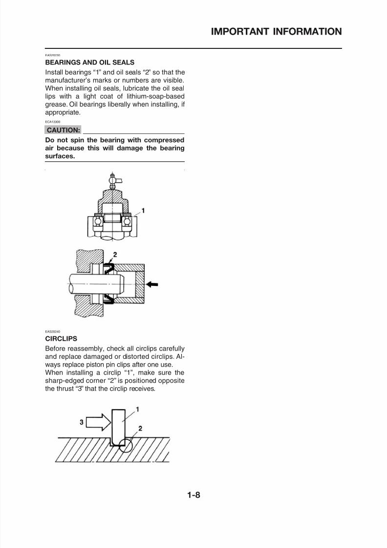
BEARINGS AND OIL SEALS
Install bearings “1” and oil seals “2” so that themanufacturer’s marks or numbers are visible.When installing oil seals, lubricate the oil seallips with a light coat of lithium-soap-basedgrease. Oil bearings liberally when installing, ifappropriate.
ECA13300
CAUTION:
Do not spin the bearing with compressed
air because this will damage the bearing
surfaces.
8/12/2019 Yamaha Tenere XT660Z Service Manual
http://slidepdf.com/reader/full/yamaha-tenere-xt660z-service-manual 17/398
CHECKING THE CONNECTIONS
EAS20250
CHECKING THE CONNECTIONS
Check the leads, couplers, and connectors forstains, rust, moisture, etc.1. Disconnect:
• Lead• Coupler• Connector
2. Check:• Lead
• Coupler• Connector
Moisture→ Dry with an air blower.Rust/stains→ Connect and disconnect sev-eral times.
3. Check:• All connections
Loose connection → Connect properly.
NOTE:
If the pin “1” on the terminal is flattened bend
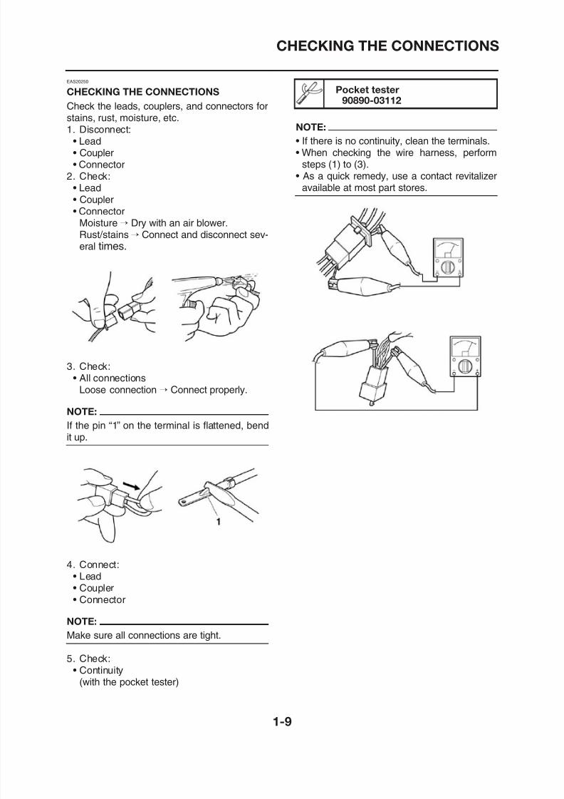
Pocket tester
90890-03112
NOTE:
• If there is no continuity, clean the terminals.• When checking the wire harness, perform
steps (1) to (3).• As a quick remedy, use a contact revitalizer
available at most part stores.
8/12/2019 Yamaha Tenere XT660Z Service Manual
http://slidepdf.com/reader/full/yamaha-tenere-xt660z-service-manual 18/398
SPECIAL TOOLS
EAS00027
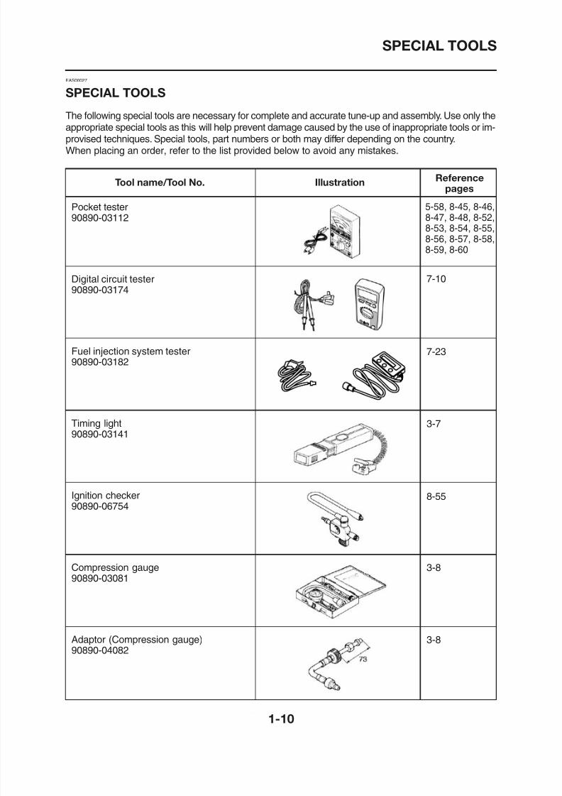
SPECIAL TOOLS
The following special tools are necessary for complete and accurate tune-up and assembly. Use only theappropriate special tools as this will help prevent damage caused by the use of inappropriate tools or im-provised techniques. Special tools, part numbers or both may differ depending on the country.When placing an order, refer to the list provided below to avoid any mistakes.
Tool name/Tool No. Illustration Referencepages
Pocket tester90890-03112
Digital circuit tester90890-03174
Fuel injection system tester90890-03182
Timing light
5-58, 8-45, 8-46,
8-47, 8-48, 8-52,
8-53, 8-54, 8-55,
8-56, 8-57, 8-58,
8-59, 8-60
7-10
7-23
3 7
8/12/2019 Yamaha Tenere XT660Z Service Manual
http://slidepdf.com/reader/full/yamaha-tenere-xt660z-service-manual 19/398
SPECIAL TOOLS
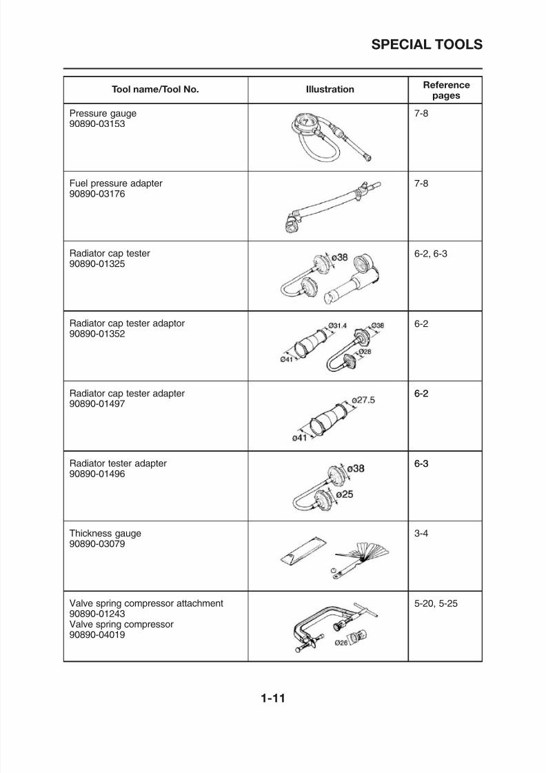
Tool name/Tool No. Illustration Reference
pages
Pressure gauge90890-03153
Fuel pressure adapter
90890-03176
Radiator cap tester90890-01325
Radiator cap tester adaptor90890-01352
Radiator cap tester adapter90890-01497
7-8
7-8
6-2, 6-3
6-2
6-26-2
8/12/2019 Yamaha Tenere XT660Z Service Manual
http://slidepdf.com/reader/full/yamaha-tenere-xt660z-service-manual 20/398
SPECIAL TOOLS
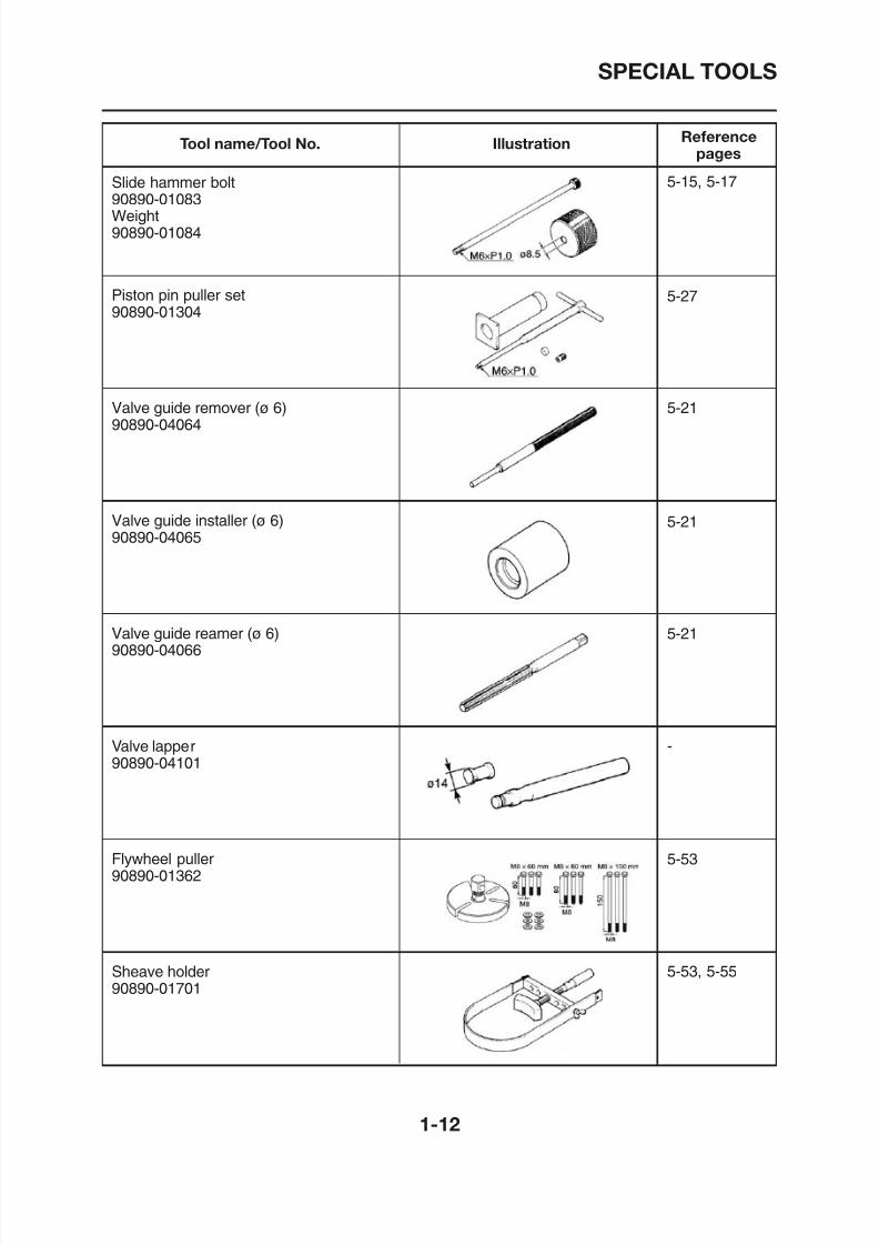
Tool name/Tool No. Illustration Reference
pages
Slide hammer bolt90890-01083Weight90890-01084
Piston pin puller set
90890-01304
Valve guide remover (ø 6)90890-04064
Valve guide installer (ø 6)90890-04065
Valve guide reamer (ø 6)90890-04066
5-15, 5-17
5-27
5-21
5-21
5-21
8/12/2019 Yamaha Tenere XT660Z Service Manual
http://slidepdf.com/reader/full/yamaha-tenere-xt660z-service-manual 21/398
SPECIAL TOOLS
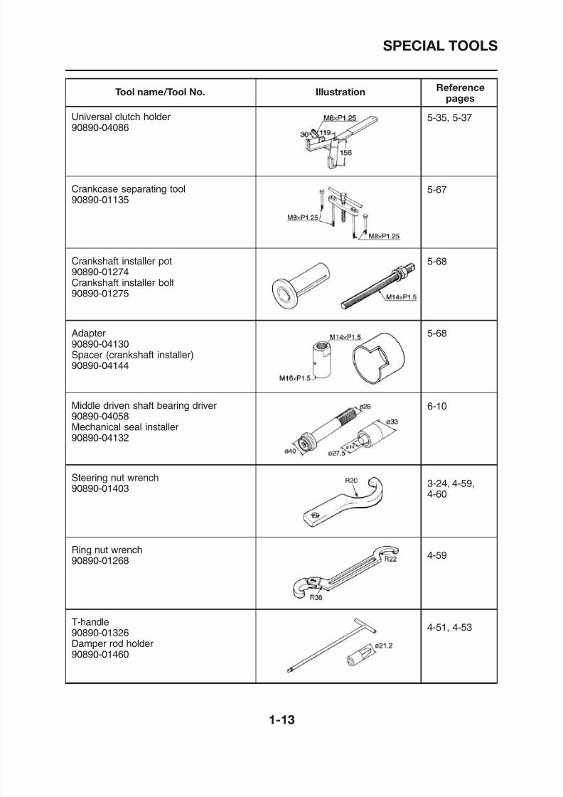
Tool name/Tool No. Illustration Reference
pages
Universal clutch holder90890-04086
Crankcase separating tool
90890-01135
Crankshaft installer pot90890-01274Crankshaft installer bolt
90890-01275
Adapter90890-04130Spacer (crankshaft installer)90890-04144
Middle driven shaft bearing driver90890-04058
5-35, 5-37
5-67
5-68
5-68
6-10
8/12/2019 Yamaha Tenere XT660Z Service Manual
http://slidepdf.com/reader/full/yamaha-tenere-xt660z-service-manual 22/398
SPECIAL TOOLS
Tool name/Tool No. Illustration Reference
pages
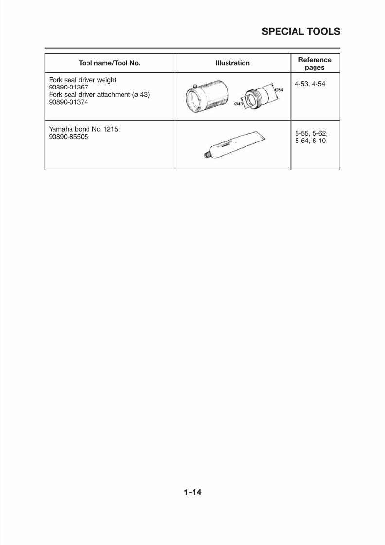
Fork seal driver weight90890-01367Fork seal driver attachment (ø 43)90890-01374
Yamaha bond No. 1215
90890-85505
4-53, 4-54
5-55, 5-62,5-64, 6-10
8/12/2019 Yamaha Tenere XT660Z Service Manual
http://slidepdf.com/reader/full/yamaha-tenere-xt660z-service-manual 23/398
SPECIFICATIONS
GENERAL SPECIFICATIONS........................................................................ 2-1
ENGINE SPECIFICATIONS .......................................................................... 2-2
CHASSIS SPECIFICATIONS .........................................................................2-10
ELECTRICAL SPECIFICATIONS ..................................................................2-13
TIGHTENING TORQUES ...............................................................................2-16GENERAL TIGHTENING TORQUE SPECIFICATIONS ..........................2-16ENGINE TIGHTENING TORQUES ..........................................................2-17CHASSIS TIGHTENING TORQUES........................................................2-21
LUBRICATION POINTS AND LUBRICANT TYPES .....................................2-25ENGINE....................................................................................................2-25CHASSIS..................................................................................................2-27
COOLING SYSTEM DIAGRAMS...................................................................2-28
LUBRICATION CHART ..................................................................................2-32LUBRICATION DIAGRAMS......................................................................2-33
CABLE ROUTING .........................................................................................2-41
2

8/12/2019 Yamaha Tenere XT660Z Service Manual
http://slidepdf.com/reader/full/yamaha-tenere-xt660z-service-manual 24/398
8/12/2019 Yamaha Tenere XT660Z Service Manual
http://slidepdf.com/reader/full/yamaha-tenere-xt660z-service-manual 25/398
GENERAL SPECIFICATIONS
GENERAL SPECIFICATIONS
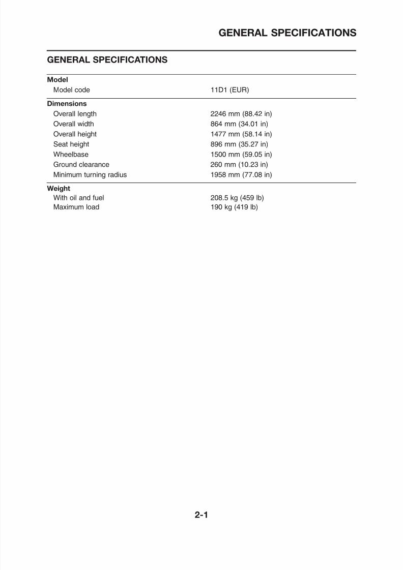
Model
Model code 11D1 (EUR)
Dimensions
Overall length 2246 mm (88.42 in)
Overall width 864 mm (34.01 in)
Overall height 1477 mm (58.14 in)
Seat height 896 mm (35.27 in)
Wheelbase 1500 mm (59.05 in)
Ground clearance 260 mm (10.23 in)
Minimum turning radius 1958 mm (77.08 in)
Weight
With oil and fuel 208.5 kg (459 lb)
Maximum load 190 kg (419 lb)
8/12/2019 Yamaha Tenere XT660Z Service Manual
http://slidepdf.com/reader/full/yamaha-tenere-xt660z-service-manual 26/398
ENGINE SPECIFICATIONS
ENGINE SPECIFICATIONS
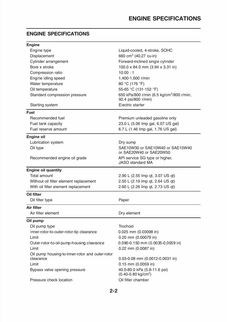
Engine
Engine type Liquid-cooled, 4-stroke, SOHC
Displacement 660 cm3 (40.27 cu·in)
Cylinder arrangement Forward-inclined single cylinder
Bore x stroke 100.0 x 84.0 mm (3.94 x 3.31 in)
Compression ratio 10.00 : 1
Engine idling speed 1,400-1,600 r/min
Water temperature 80 °C (176 °F)
Oil temperature 55-65 °C (131-152 °F)
Standard compression pressure 650 kPa/800 r/min (6.5 kg/cm2 /800 r/min,92.4 psi/800 r/min)
Starting system Electric starter
Fuel
Recommended fuel Premium unleaded gasoline onlyFuel tank capacity 23.0 L (5.06 Imp gal, 6.07 US gal)
Fuel reserve amount 6.7 L (1.46 Imp gal, 1.76 US gal)
Engine oil
Lubrication system Dry sump
Oil type SAE10W30 or SAE10W40 or SAE15W40or SAE20W40 or SAE20W50
Recommended engine oil grade API service SG type or higher,JASO standard MA
Engine oil quantity
8/12/2019 Yamaha Tenere XT660Z Service Manual
http://slidepdf.com/reader/full/yamaha-tenere-xt660z-service-manual 27/398
ENGINE SPECIFICATIONS
Cooling system
Radiator capacity (including all routes) 1.20 L (1.25 US qt) (1.06 Imp.qt)Coolant reservoir capacity 0.50 L (0.52 US qt) (0.44 Imp.qt)(up to the maximum level mark)
Radiator cap opening pressure 110.0-140.0 kPa (16.0-20.3 psi)(1.10-1.40 kg/cm2)
Radiator core
Width 332.0 mm (13.07 in)
Height 158.0 mm (6.22 in)Depth 23.0 mm (0.91 in)
Water pump
Water pump type Single suction centrifugal pump
Reduction ratio 27/28 (0.964)
Maximum impeller shaft tilt 0.15 mm (0.006 in)
Spark plugManufacturer/Model NGK/CR7E
Spark plug gap 0.7-0.8 mm (0.028-0.031 in)
Cylinder head
Volume 59.10-60.50 cm3 (3.61-3.69 cu·in)
Maximum warpage* 0.03 mm (0.0012 in)
8/12/2019 Yamaha Tenere XT660Z Service Manual
http://slidepdf.com/reader/full/yamaha-tenere-xt660z-service-manual 28/398
ENGINE SPECIFICATIONS
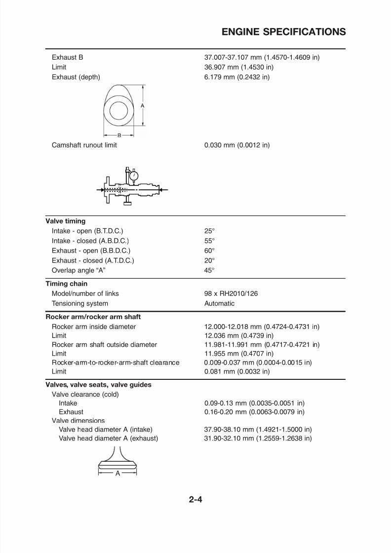
Exhaust B 37.007-37.107 mm (1.4570-1.4609 in)
Limit 36.907 mm (1.4530 in)Exhaust (depth) 6.179 mm (0.2432 in)
Camshaft runout limit 0.030 mm (0.0012 in)
Valve timing
Intake - open (B.T.D.C.) 25°
Intake - closed (A.B.D.C.) 55°
Exhaust - open (B.B.D.C.) 60°
Exhaust - closed (A.T.D.C.) 20°
Overlap angle “A” 45°
Timing chain
Model/number of links 98 x RH2010/126
8/12/2019 Yamaha Tenere XT660Z Service Manual
http://slidepdf.com/reader/full/yamaha-tenere-xt660z-service-manual 29/398
ENGINE SPECIFICATIONS
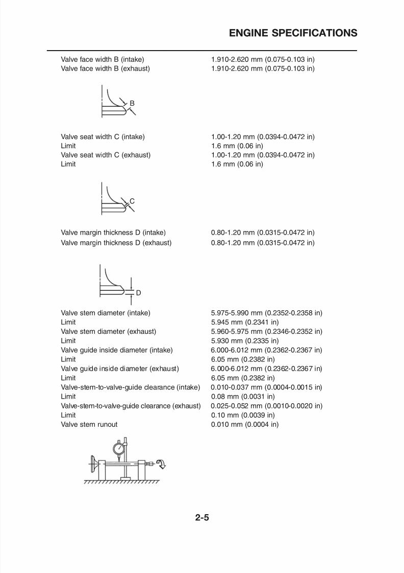
Valve face width B (intake) 1.910-2.620 mm (0.075-0.103 in)
Valve face width B (exhaust) 1.910-2.620 mm (0.075-0.103 in)
Valve seat width C (intake) 1.00-1.20 mm (0.0394-0.0472 in)
Limit 1.6 mm (0.06 in)
Valve seat width C (exhaust) 1.00-1.20 mm (0.0394-0.0472 in)
Limit 1.6 mm (0.06 in)
Valve margin thickness D (intake) 0.80-1.20 mm (0.0315-0.0472 in)
Valve margin thickness D (exhaust) 0.80-1.20 mm (0.0315-0.0472 in)
D
C
B
8/12/2019 Yamaha Tenere XT660Z Service Manual
http://slidepdf.com/reader/full/yamaha-tenere-xt660z-service-manual 30/398
ENGINE SPECIFICATIONS
Cylinder head valve seat width (intake) 1.00-1.20 mm (0.0394-0.0472 in)
Limit 1.6 mm (0.06 in)Cylinder head valve seat width (exhaust) 1.00-1.20 mm (0.0394-0.0472 in)
Limit 1.6 mm (0.06 in)
Valve face material Stellite
Valve seat material (intake) PB6
Valve seat material (exhaust) PB1W
Valve springs
Free length (intake) 40.38 mm (1.59 in)Limit 38.36 mm (1.51 in)
Free length (exhaust) 40.38 mm (1.59 in)
Limit 38.36 mm (1.51 in)
Installed length (valve closed) (intake) 35.00 mm (1.38 in)
Installed length (valve closed) (exhaust) 35.00 mm (1.38 in)
Spring rate (K1) (intake) 34.18 N/mm
Spring rate (K2) (intake) 44.14 N/mm
Spring rate (K1) (exhaust) 34.18 N/mm
Spring rate (K2) (exhaust) 44.14 N/mm
Installed compression spring force 171.00-197.00 N (38.44-44.29 lb)
(intake) (17.44-20.09 kg)
Installed compression spring force 171.00-197.00 N (38.44-44.29 lb)
(exhaust) (17.44-20.09 kg)
Spring tilt (intake)* 2.5°/1.8 mm
Spring tilt (exhaust)* 2.5°/1.8 mm
8/12/2019 Yamaha Tenere XT660Z Service Manual
http://slidepdf.com/reader/full/yamaha-tenere-xt660z-service-manual 31/398
ENGINE SPECIFICATIONS
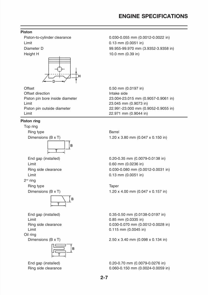
Piston
Piston-to-cylinder clearance 0.030-0.055 mm (0.0012-0.0022 in)Limit 0.13 mm (0.0051 in)
Diameter D 99.955-99.970 mm (3.9352-3.9358 in)
Height H 10.0 mm (0.39 in)
Offset 0.50 mm (0.0197 in)
Offset direction Intake side
Piston pin bore inside diameter 23.004-23.015 mm (0.9057-0.9061 in)
Limit 23.045 mm (0.9073 in)
Piston pin outside diameter 22.991-23.000 mm (0.9052-0.9055 in)Limit 22.971 mm (0.9044 in)
Piston ring
Top ring
Ring type Barrel
Dimensions (B x T) 1.20 x 3.80 mm (0.047 x 0.150 in)
8/12/2019 Yamaha Tenere XT660Z Service Manual
http://slidepdf.com/reader/full/yamaha-tenere-xt660z-service-manual 32/398
ENGINE SPECIFICATIONS
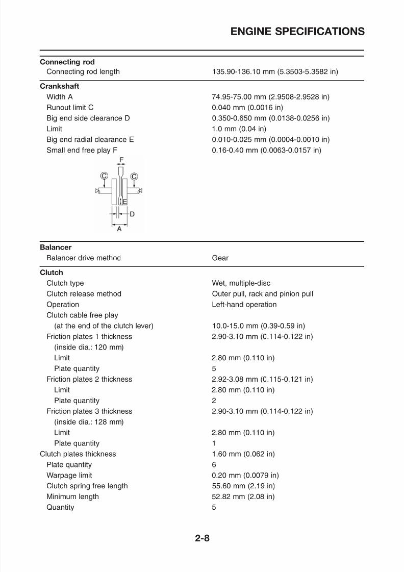
Connecting rod
Connecting rod length 135.90-136.10 mm (5.3503-5.3582 in)
Crankshaft
Width A 74.95-75.00 mm (2.9508-2.9528 in)
Runout limit C 0.040 mm (0.0016 in)
Big end side clearance D 0.350-0.650 mm (0.0138-0.0256 in)
Limit 1.0 mm (0.04 in)
Big end radial clearance E 0.010-0.025 mm (0.0004-0.0010 in)Small end free play F 0.16-0.40 mm (0.0063-0.0157 in)
Balancer
Balancer drive method Gear
Clutch
Clutch type Wet, multiple-discClutch release method Outer pull, rack and pinion pull
Operation Left hand operation
8/12/2019 Yamaha Tenere XT660Z Service Manual
http://slidepdf.com/reader/full/yamaha-tenere-xt660z-service-manual 33/398
ENGINE SPECIFICATIONS
Transmission
Transmission type Constant mesh, 5-speedPrimary reduction system Spur gear
Primary reduction ratio 75/36 (2.083)
Secondary reduction system Chain drive
Secondary reduction ratio 45/15 (3.000)
Operation Left-foot operation
Gear ratios
1st
gear 30/12 (2.500)2nd gear 26/16 (1.625)
3rd gear 23/20 (1.150)
4th gear 20/22 (0.909)
5th gear 20/26 (0.769)
Main axle runout limit 0.08 mm (0.0031 in)
Drive axle runout limit 0.08 mm (0.0031 in)
Shifting mechanism
Shift mechanism type Shift drum and guide bar
Shift fork thickness 5.76-5.89 mm (0.2267-0.23188 in)
Decompression device
Device type Auto decompression
Air filter
Air filter type Paper
Fuel pump
8/12/2019 Yamaha Tenere XT660Z Service Manual
http://slidepdf.com/reader/full/yamaha-tenere-xt660z-service-manual 34/398
CHASSIS SPECIFICATIONS
CHASSIS SPECIFICATIONS
Frame
Frame type Diamond
Caster angle 28°
Trail 113.0 mm (4.44 in)
Front wheel
Wheel type Spoke wheel
Rim size 21 x 1.85Material Aluminum
Wheel travel 210 mm (8.26 in)
Radial wheel runout limit 1.2 mm (0.047 in)
Lateral wheel runout limit 0.8 mm (0.031 in)
Rear wheel
Wheel type Spoke wheel
Rim size 17M/C x MT2,75
Material Aluminum
Wheel travel 200 mm (7.87 in)
Radial wheel runout limit 1.2 mm (0.047 in)
Lateral wheel runout limit 0.8 mm (0.031 in)
Front tire
Tire type With tubeSize 90/90-21M/C 54S, 90/90-21M/C 54T
M f t / d l METZELER/TOURANCE FRONT
8/12/2019 Yamaha Tenere XT660Z Service Manual
http://slidepdf.com/reader/full/yamaha-tenere-xt660z-service-manual 35/398
CHASSIS SPECIFICATIONS
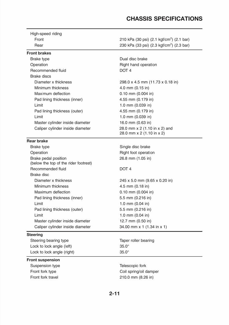
High-speed riding
Front 210 kPa (30 psi) (2.1 kgf/cm
2
) (2.1 bar)Rear 230 kPa (33 psi) (2.3 kgf/cm2) (2.3 bar)
Front brakes
Brake type Dual disc brake
Operation Right hand operation
Recommended fluid DOT 4
Brake discs
Diameter x thickness 298.0 x 4.5 mm (11.73 x 0.18 in)Minimum thickness 4.0 mm (0.15 in)
Maximum deflection 0.10 mm (0.004 in)
Pad lining thickness (inner) 4.55 mm (0.179 in)
Limit 1.0 mm (0.039 in)
Pad lining thickness (outer) 4.55 mm (0.179 in)
Limit 1.0 mm (0.039 in)
Master cylinder inside diameter 16.0 mm (0.63 in)
Caliper cylinder inside diameter 28.0 mm x 2 (1.10 in x 2) and28.0 mm x 2 (1.10 in x 2)
Rear brake
Brake type Single disc brake
Operation Right foot operation
Brake pedal position 26.8 mm (1.05 in)
(below the top of the rider footrest)
Recommended fluid DOT 4
8/12/2019 Yamaha Tenere XT660Z Service Manual
http://slidepdf.com/reader/full/yamaha-tenere-xt660z-service-manual 36/398
CHASSIS SPECIFICATIONS
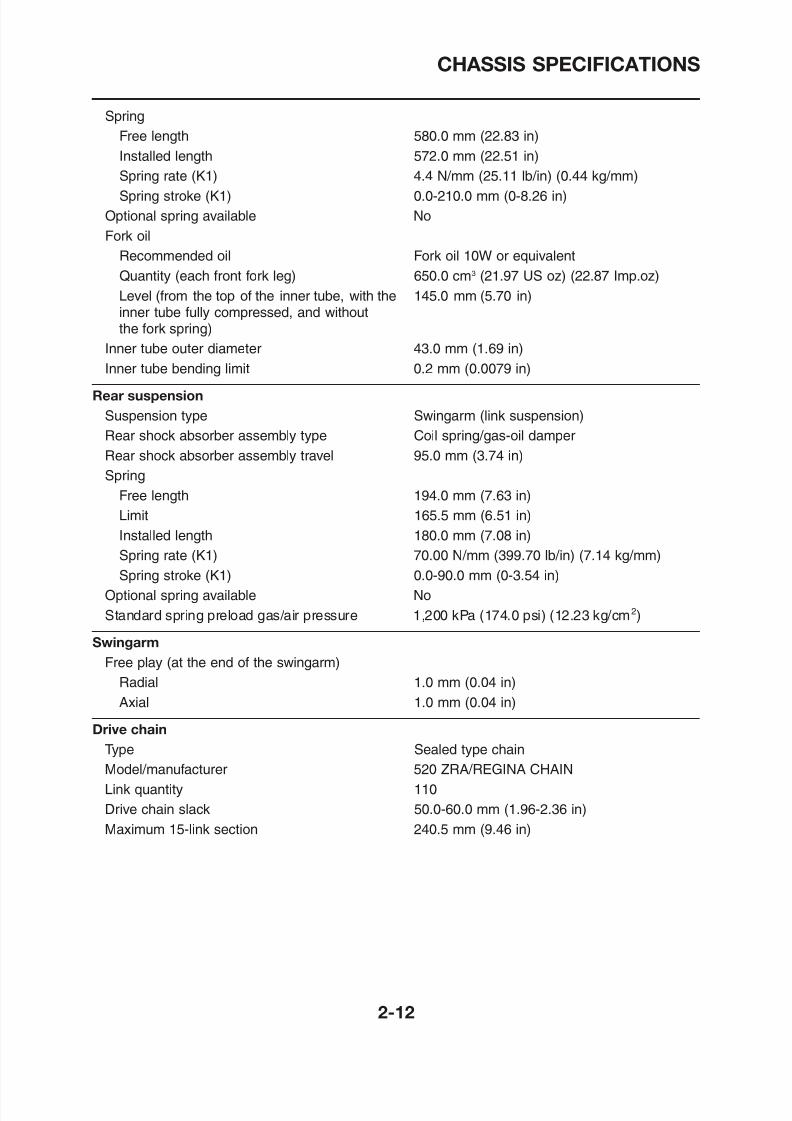
Spring
Free length 580.0 mm (22.83 in)Installed length 572.0 mm (22.51 in)
Spring rate (K1) 4.4 N/mm (25.11 lb/in) (0.44 kg/mm)
Spring stroke (K1) 0.0-210.0 mm (0-8.26 in)
Optional spring available No
Fork oil
Recommended oil Fork oil 10W or equivalent
Quantity (each front fork leg) 650.0 cm3
(21.97 US oz) (22.87 Imp.oz)Level (from the top of the inner tube, with the 145.0 mm (5.70 in)inner tube fully compressed, and withoutthe fork spring)
Inner tube outer diameter 43.0 mm (1.69 in)
Inner tube bending limit 0.2 mm (0.0079 in)
Rear suspension
Suspension type Swingarm (link suspension)Rear shock absorber assembly type Coil spring/gas-oil damper
Rear shock absorber assembly travel 95.0 mm (3.74 in)
Spring
Free length 194.0 mm (7.63 in)
Limit 165.5 mm (6.51 in)
Installed length 180.0 mm (7.08 in)
Spring rate (K1) 70.00 N/mm (399.70 lb/in) (7.14 kg/mm)Spring stroke (K1) 0.0-90.0 mm (0-3.54 in)
Optional spring available No
8/12/2019 Yamaha Tenere XT660Z Service Manual
http://slidepdf.com/reader/full/yamaha-tenere-xt660z-service-manual 37/398
ELECTRICAL SPECIFICATIONS
ELECTRICAL SPECIFICATIONS
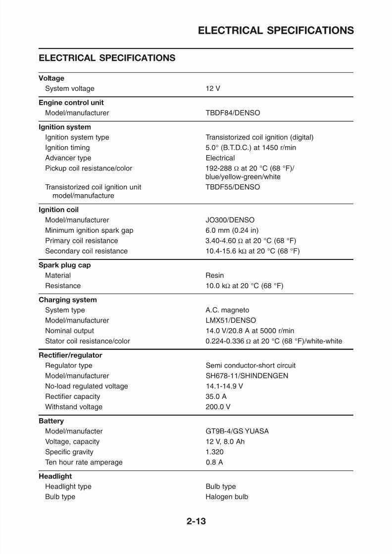
Voltage
System voltage 12 V
Engine control unit
Model/manufacturer TBDF84/DENSO
Ignition system
Ignition system type Transistorized coil ignition (digital)Ignition timing 5.0° (B.T.D.C.) at 1450 r/min
Advancer type Electrical
Pickup coil resistance/color 192-288 Ω at 20 °C (68 °F)/ blue/yellow-green/white
Transistorized coil ignition unit TBDF55/DENSOmodel/manufacture
Ignition coil
Model/manufacturer JO300/DENSO
Minimum ignition spark gap 6.0 mm (0.24 in)
Primary coil resistance 3.40-4.60 Ω at 20 °C (68 °F)
Secondary coil resistance 10.4-15.6 kΩ at 20 °C (68 °F)
Spark plug cap
Material ResinResistance 10.0 kΩ at 20 °C (68 °F)
8/12/2019 Yamaha Tenere XT660Z Service Manual
http://slidepdf.com/reader/full/yamaha-tenere-xt660z-service-manual 38/398
ELECTRICAL SPECIFICATIONS
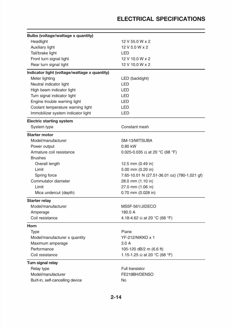
Bulbs (voltage/wattage x quantity)
Headlight 12 V 55.0 W x 2Auxiliary light 12 V 5.0 W x 2
Tail/brake light LED
Front turn signal light 12 V 10.0 W x 2
Rear turn signal light 12 V 10.0 W x 2
Indicator light (voltage/wattage x quantity)
Meter lighting LED (backlight)
Neutral indicator light LED
High beam indicator light LED
Turn signal indicator light LED
Engine trouble warning light LED
Coolant temperature warning light LED
Immobilizer system indicator light LED
Electric starting system
System type Constant mesh
Starter motor
Model/manufacturer SM-13/MITSUBA
Power output 0.80 kW
Armature coil resistance 0.025-0.035 Ω at 20 °C (68 °F)
Brushes
Overall length 12.5 mm (0.49 in)Limit 5.00 mm (0.20 in)
Spring force 7 65 10 01 N (27 51 36 01 o ) (780 1 021 gf)
8/12/2019 Yamaha Tenere XT660Z Service Manual
http://slidepdf.com/reader/full/yamaha-tenere-xt660z-service-manual 39/398
ELECTRICAL SPECIFICATIONS
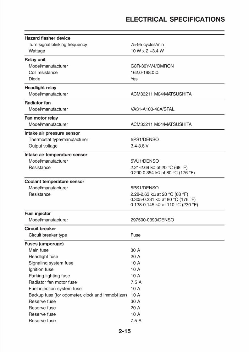
Hazard flasher device
Turn signal blinking frequency 75-95 cycles/minWattage 10 W x 2 +3.4 W
Relay unit
Model/manufacturer G8R-30Y-V4/OMRON
Coil resistance 162.0-198.0 Ω
Diode Yes
Headlight relay Model/manufacturer ACM33211 M04/MATSUSHITA
Radiator fan
Model/manufacturer VA31-A100-46A/SPAL
Fan motor relay
Model/manufacturer ACM33211 M04/MATSUSHITA
Intake air pressure sensor
Thermostat type/manufacturer 5PS1/DENSO
Output voltage 3.4-3.8 V
Intake air temperature sensor
Model/manufacturer 5VU1/DENSO
Resistance 2.21-2.69 kΩ at 20 °C (68 °F)0.290-0.354 kΩ at 80 °C (176 °F)
Coolant temperature sensor
M d l/ f t 5PS1/DENSO
8/12/2019 Yamaha Tenere XT660Z Service Manual
http://slidepdf.com/reader/full/yamaha-tenere-xt660z-service-manual 40/398
TIGHTENING TORQUES
TIGHTENING TORQUES
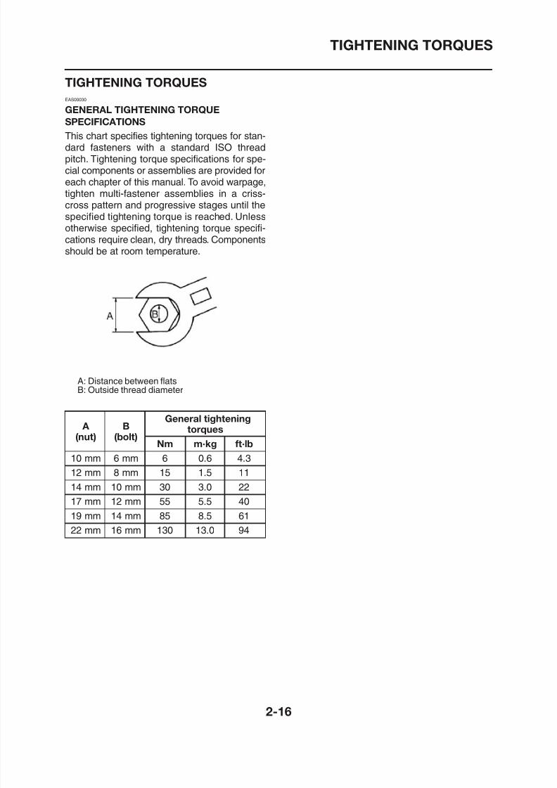
EAS00030
GENERAL TIGHTENING TORQUE
SPECIFICATIONS
This chart specifies tightening torques for stan-dard fasteners with a standard ISO threadpitch. Tightening torque specifications for spe-cial components or assemblies are provided foreach chapter of this manual. To avoid warpage,
tighten multi-fastener assemblies in a criss-cross pattern and progressive stages until thespecified tightening torque is reached. Unlessotherwise specified, tightening torque specifi-cations require clean, dry threads. Componentsshould be at room temperature.
A: Distance between flats
B: Outside thread diameter
General tightening
8/12/2019 Yamaha Tenere XT660Z Service Manual
http://slidepdf.com/reader/full/yamaha-tenere-xt660z-service-manual 41/398
TIGHTENING TORQUES
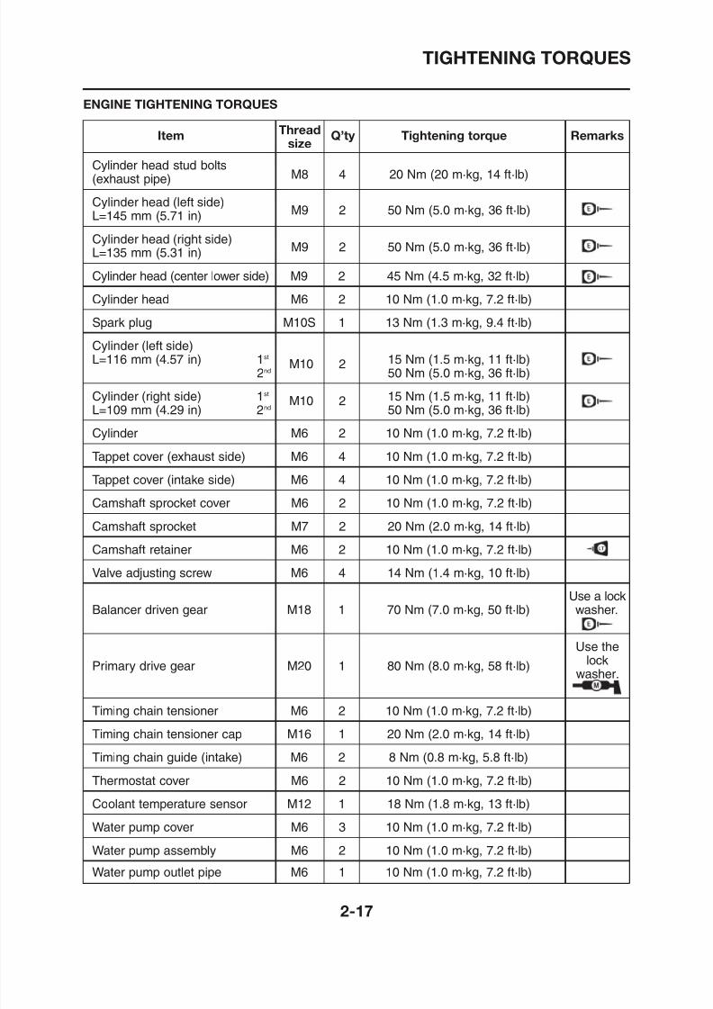
ENGINE TIGHTENING TORQUES
Item Thread Q’ty Tightening torque Remarkssize
Cylinder head stud bolts(exhaust pipe) M8 4 20 Nm (20 m·kg, 14 ft·lb)
Cylinder head (left side)L=145 mm (5.71 in) M9 2 50 Nm (5.0 m·kg, 36 ft·lb)
Cylinder head (right side)
L=135 mm (5.31 in)M9 2 50 Nm (5.0 m·kg, 36 ft·lb)
Cylinder head (center lower side) M9 2 45 Nm (4.5 m·kg, 32 ft·lb)
Cylinder head M6 2 10 Nm (1.0 m·kg, 7.2 ft·lb)
Spark plug M10S 1 13 Nm (1.3 m·kg, 9.4 ft·lb)
Cylinder (left side)L=116 mm (4.57 in) 1st
M10 2 15 Nm (1.5 m·kg, 11 ft·lb)
2nd
50 Nm (5.0 m·kg, 36 ft·lb)Cylinder (right side) 1st
M10 2 15 Nm (1.5 m·kg, 11 ft·lb)L=109 mm (4.29 in) 2nd 50 Nm (5.0 m·kg, 36 ft·lb)
Cylinder M6 2 10 Nm (1.0 m·kg, 7.2 ft·lb)
Tappet cover (exhaust side) M6 4 10 Nm (1.0 m·kg, 7.2 ft·lb)
Tappet cover (intake side) M6 4 10 Nm (1.0 m·kg, 7.2 ft·lb)
Camshaft sprocket cover M6 2 10 Nm (1.0 m·kg, 7.2 ft·lb)
Camshaft sprocket M7 2 20 Nm (2.0 m·kg, 14 ft·lb)
8/12/2019 Yamaha Tenere XT660Z Service Manual
http://slidepdf.com/reader/full/yamaha-tenere-xt660z-service-manual 42/398
TIGHTENING TORQUES
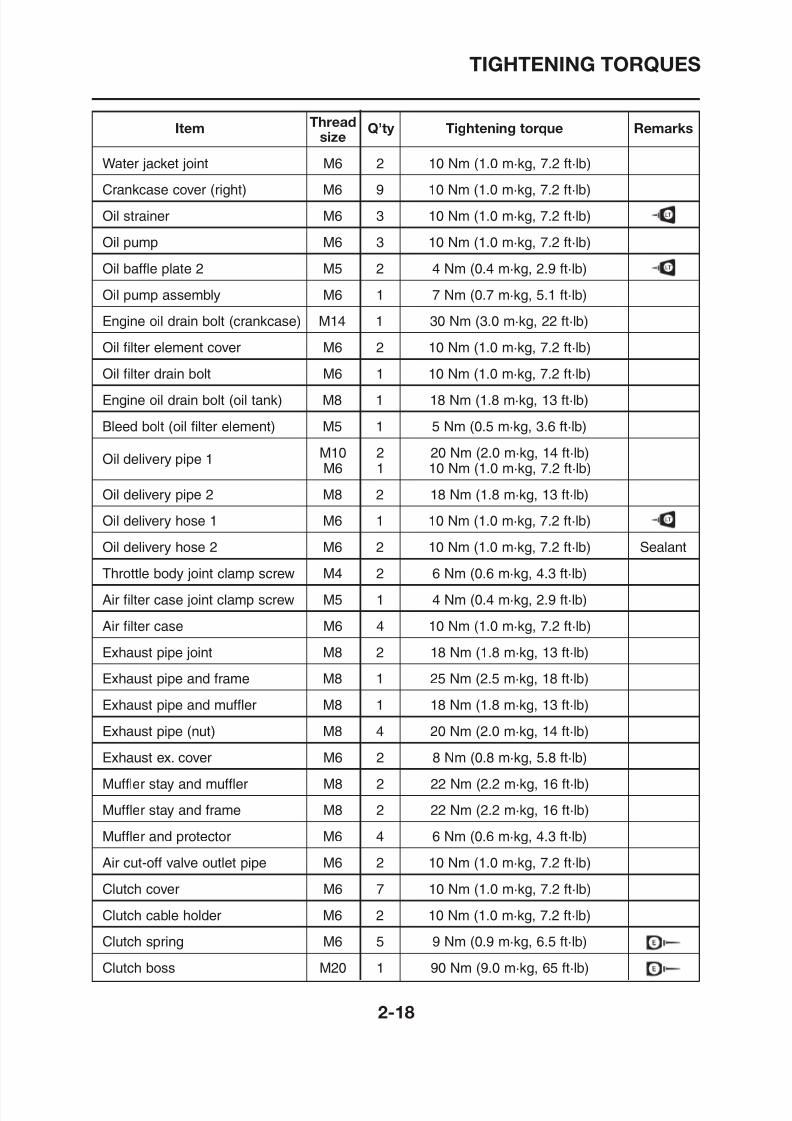
Item Thread Q’ty Tightening torque Remarkssize
Water jacket joint M6 2 10 Nm (1.0 m·kg, 7.2 ft·lb)
Crankcase cover (right) M6 9 10 Nm (1.0 m·kg, 7.2 ft·lb)
Oil strainer M6 3 10 Nm (1.0 m·kg, 7.2 ft·lb)
Oil pump M6 3 10 Nm (1.0 m·kg, 7.2 ft·lb)
Oil baffle plate 2 M5 2 4 Nm (0.4 m·kg, 2.9 ft·lb)
Oil pump assembly M6 1 7 Nm (0.7 m·kg, 5.1 ft·lb)
Engine oil drain bolt (crankcase) M14 1 30 Nm (3.0 m·kg, 22 ft·lb)
Oil filter element cover M6 2 10 Nm (1.0 m·kg, 7.2 ft·lb)
Oil filter drain bolt M6 1 10 Nm (1.0 m·kg, 7.2 ft·lb)
Engine oil drain bolt (oil tank) M8 1 18 Nm (1.8 m·kg, 13 ft·lb)
Bleed bolt (oil filter element) M5 1 5 Nm (0.5 m·kg, 3.6 ft·lb)
Oil delivery pipe 1 M10 2 20 Nm (2.0 m·kg, 14 ft·lb)M6 1 10 Nm (1.0 m·kg, 7.2 ft·lb)
Oil delivery pipe 2 M8 2 18 Nm (1.8 m·kg, 13 ft·lb)
Oil delivery hose 1 M6 1 10 Nm (1.0 m·kg, 7.2 ft·lb)
Oil delivery hose 2 M6 2 10 Nm (1.0 m·kg, 7.2 ft·lb) Sealant
Throttle body joint clamp screw M4 2 6 Nm (0.6 m·kg, 4.3 ft·lb)
( )
8/12/2019 Yamaha Tenere XT660Z Service Manual
http://slidepdf.com/reader/full/yamaha-tenere-xt660z-service-manual 43/398
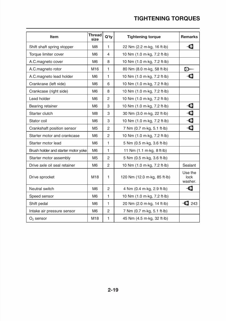
TIGHTENING TORQUES
Item Thread Q’ty Tightening torque Remarkssize
Shift shaft spring stopper M8 1 22 Nm (2.2 m·kg, 16 ft·lb)
Torque limiter cover M6 4 10 Nm (1.0 m·kg, 7.2 ft·lb)
A.C.magneto cover M6 8 10 Nm (1.0 m·kg, 7.2 ft·lb)
A.C.magneto rotor M16 1 80 Nm (8.0 m·kg, 58 ft·lb)
A.C.magneto lead holder M6 1 10 Nm (1.0 m·kg, 7.2 ft·lb)
Crankcase (left side) M6 6 10 Nm (1.0 m·kg, 7.2 ft·lb)
Crankcase (right side) M6 8 10 Nm (1.0 m·kg, 7.2 ft·lb)
Lead holder M6 2 10 Nm (1.0 m·kg, 7.2 ft·lb)
Bearing retainer M6 3 10 Nm (1.0 m·kg, 7.2 ft·lb)
Starter clutch M8 3 30 Nm (3.0 m·kg, 22 ft·lb)
Stator coil M6 3 10 Nm (1.0 m·kg, 7.2 ft·lb)
Crankshaft position sensor M5 2 7 Nm (0.7 m·kg, 5.1 ft·lb)
Starter motor and crankcase M6 2 10 Nm (1.0 m·kg, 7.2 ft·lb)
Starter motor lead M6 1 5 Nm (0.5 m·kg, 3.6 ft·lb)
Brush holder and starter motor yoke M6 1 11 Nm (1.1 m·kg, 8 ft·lb)
Starter motor assembly M5 2 5 Nm (0.5 m·kg, 3.6 ft·lb)
Drive axle oil seal retainer M6 2 10 Nm (1.0 m·kg, 7.2 ft·lb) Sealant
8/12/2019 Yamaha Tenere XT660Z Service Manual
http://slidepdf.com/reader/full/yamaha-tenere-xt660z-service-manual 44/398
8/12/2019 Yamaha Tenere XT660Z Service Manual
http://slidepdf.com/reader/full/yamaha-tenere-xt660z-service-manual 45/398
TIGHTENING TORQUES
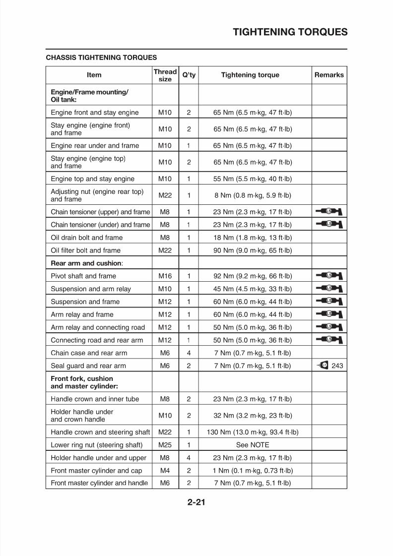
Item Thread Q’ty Tightening torque Remarkssize
Engine/Frame mounting/ Oil tank:
Engine front and stay engine M10 2 65 Nm (6.5 m·kg, 47 ft·lb)
Stay engine (engine front)and frame
M10 2 65 Nm (6.5 m·kg, 47 ft·lb)
Engine rear under and frame M10 1 65 Nm (6.5 m·kg, 47 ft·lb)
Stay engine (engine top)and frame
M10 2 65 Nm (6.5 m·kg, 47 ft·lb)
Engine top and stay engine M10 1 55 Nm (5.5 m·kg, 40 ft·lb)
Adjusting nut (engine rear top)and frame
M22 1 8 Nm (0.8 m·kg, 5.9 ft·lb)
Chain tensioner (upper) and frame M8 1 23 Nm (2.3 m·kg, 17 ft·lb)
Chain tensioner (under) and frame M8 1 23 Nm (2.3 m·kg, 17 ft·lb)
Oil drain bolt and frame M8 1 18 Nm (1.8 m·kg, 13 ft·lb)
Oil filter bolt and frame M22 1 90 Nm (9.0 m·kg, 65 ft·lb)
Rear arm and cushion:
Pivot shaft and frame M16 1 92 Nm (9.2 m·kg, 66 ft·lb)
Suspension and arm relay M10 1 45 Nm (4.5 m·kg, 33 ft·lb)
CHASSIS TIGHTENING TORQUES
8/12/2019 Yamaha Tenere XT660Z Service Manual
http://slidepdf.com/reader/full/yamaha-tenere-xt660z-service-manual 46/398
TIGHTENING TORQUES
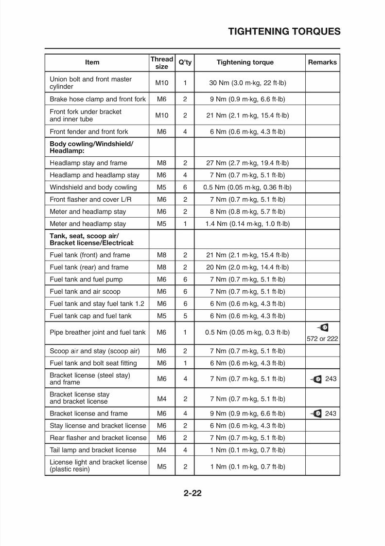
Item Thread Q’ty Tightening torque Remarkssize
Union bolt and front mastercylinder
M10 1 30 Nm (3.0 m·kg, 22 ft·lb)
Brake hose clamp and front fork M6 2 9 Nm (0.9 m·kg, 6.6 ft·lb)
Front fork under bracketand inner tube
M10 2 21 Nm (2.1 m·kg, 15.4 ft·lb)
Front fender and front fork M6 4 6 Nm (0.6 m·kg, 4.3 ft·lb)
Body cowling/Windshield/ Headlamp:
Headlamp stay and frame M8 2 27 Nm (2.7 m·kg, 19.4 ft·lb)
Headlamp and headlamp stay M6 4 7 Nm (0.7 m·kg, 5.1 ft·lb)
Windshield and body cowling M5 6 0.5 Nm (0.05 m·kg, 0.36 ft·lb)
Front flasher and cover L/R M6 2 7 Nm (0.7 m·kg, 5.1 ft·lb)
Meter and headlamp stay M6 2 8 Nm (0.8 m·kg, 5.7 ft·lb)
Meter and headlamp stay M5 1 1.4 Nm (0.14 m·kg, 1.0 ft·lb)
Tank, seat, scoop air/ Bracket license/Electrical:
Fuel tank (front) and frame M8 2 21 Nm (2.1 m·kg, 15.4 ft·lb)
Fuel tank (rear) and frame M8 2 20 Nm (2.0 m·kg, 14.4 ft·lb)
Fuel tank and fuel pump M6 6 7 Nm (0.7 m·kg, 5.1 ft·lb)
F l t k d i M6 6 7 N (0 7 k 5 1 ft lb)
8/12/2019 Yamaha Tenere XT660Z Service Manual
http://slidepdf.com/reader/full/yamaha-tenere-xt660z-service-manual 47/398
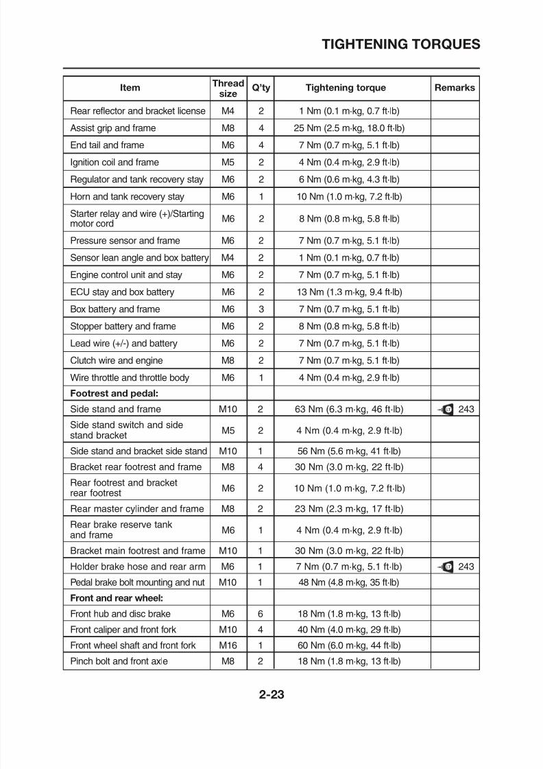
TIGHTENING TORQUES
Item Thread Q’ty Tightening torque Remarkssize
Rear reflector and bracket license M4 2 1 Nm (0.1 m·kg, 0.7 ft·lb)
Assist grip and frame M8 4 25 Nm (2.5 m·kg, 18.0 ft·lb)
End tail and frame M6 4 7 Nm (0.7 m·kg, 5.1 ft·lb)
Ignition coil and frame M5 2 4 Nm (0.4 m·kg, 2.9 ft·lb)
Regulator and tank recovery stay M6 2 6 Nm (0.6 m·kg, 4.3 ft·lb)
Horn and tank recovery stay M6 1 10 Nm (1.0 m·kg, 7.2 ft·lb)
Starter relay and wire (+)/Startingmotor cord
M6 2 8 Nm (0.8 m·kg, 5.8 ft·lb)
Pressure sensor and frame M6 2 7 Nm (0.7 m·kg, 5.1 ft·lb)
Sensor lean angle and box battery M4 2 1 Nm (0.1 m·kg, 0.7 ft·lb)
Engine control unit and stay M6 2 7 Nm (0.7 m·kg, 5.1 ft·lb)
ECU stay and box battery M6 2 13 Nm (1.3 m·kg, 9.4 ft·lb)
Box battery and frame M6 3 7 Nm (0.7 m·kg, 5.1 ft·lb)
Stopper battery and frame M6 2 8 Nm (0.8 m·kg, 5.8 ft·lb)
Lead wire (+/-) and battery M6 2 7 Nm (0.7 m·kg, 5.1 ft·lb)
Clutch wire and engine M8 2 7 Nm (0.7 m·kg, 5.1 ft·lb)
Wire throttle and throttle body M6 1 4 Nm (0.4 m·kg, 2.9 ft·lb)
Footrest and pedal:
Side stand and frame M10 2 63 Nm (6 3 m kg 46 ft lb) 243
8/12/2019 Yamaha Tenere XT660Z Service Manual
http://slidepdf.com/reader/full/yamaha-tenere-xt660z-service-manual 48/398
Item Thread Q’ty Tightening torque Remarkssize
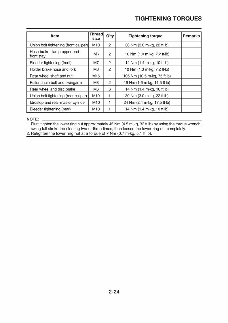
Union bolt tightening (front caliper) M10 2 30 Nm (3.0 m·kg, 22 ft·lb)
Hose brake clamp upper andfront stay
M6 2 10 Nm (1.0 m·kg, 7.2 ft·lb)
Bleeder tightening (front) M7 2 14 Nm (1.4 m·kg, 10 ft·lb)
Holder brake hose and fork M6 2 10 Nm (1.0 m·kg, 7.2 ft·lb)
Rear wheel shaft and nut M16 1 105 Nm (10.5 m·kg, 75 ft·lb)
Puller chain bolt and swingarm M8 2 16 Nm (1.6 m·kg, 11.5 ft·lb)
Rear wheel and disc brake M6 6 14 Nm (1.4 m·kg, 10 ft·lb)
Union bolt tightening (rear caliper) M10 1 30 Nm (3.0 m·kg, 22 ft·lb)
Idrostop and rear master cylinder M10 1 24 Nm (2.4 m·kg, 17.5 ft·lb)
Bleeder tightening (rear) M10 1 14 Nm (1.4 m·kg, 10 ft·lb)
TIGHTENING TORQUES
NOTE:
1. First, tighten the lower ring nut approximately 45 Nm (4.5 m·kg, 33 ft·lb) by using the torque wrench,swing full stroke the steering two or three times, then loosen the lower ring nut completely.
2. Retighten the lower ring nut at a torque of 7 Nm (0.7 m·kg, 5.1 ft·lb).
8/12/2019 Yamaha Tenere XT660Z Service Manual
http://slidepdf.com/reader/full/yamaha-tenere-xt660z-service-manual 49/398
LUBRICATION POINTS AND LUBRICANT TYPES
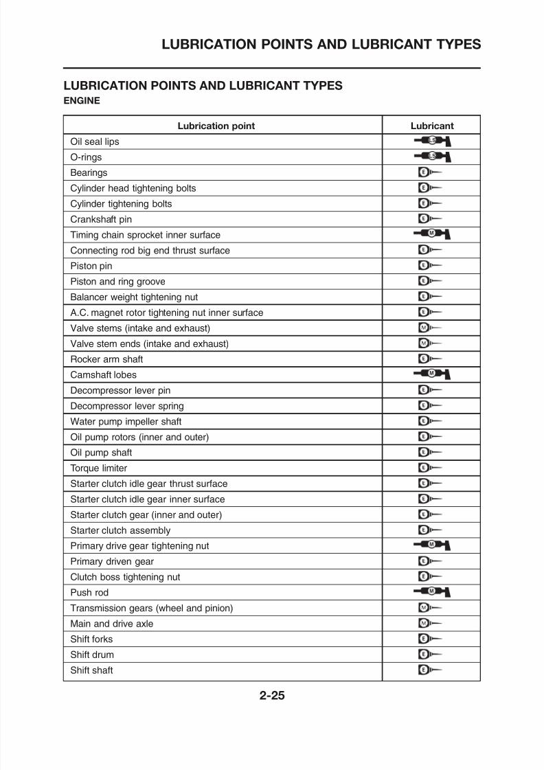
Lubrication point Lubricant
Oil seal lips
O-rings
Bearings
Cylinder head tightening bolts
Cylinder tightening bolts
Crankshaft pin
Timing chain sprocket inner surface
Connecting rod big end thrust surface
Piston pin
Piston and ring groove
Balancer weight tightening nut
A.C. magnet rotor tightening nut inner surface
Valve stems (intake and exhaust)
Valve stem ends (intake and exhaust)
Rocker arm shaft
Camshaft lobes
Decompressor lever pin
Decompressor lever spring
LUBRICATION POINTS AND LUBRICANT TYPES
ENGINE
8/12/2019 Yamaha Tenere XT660Z Service Manual
http://slidepdf.com/reader/full/yamaha-tenere-xt660z-service-manual 50/398
LUBRICATION POINTS AND LUBRICANT TYPES
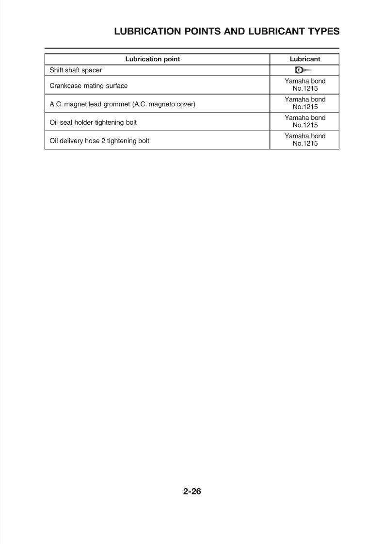
Lubrication point Lubricant
Shift shaft spacer
Crankcase mating surfaceYamaha bond
No.1215
A.C. magnet lead grommet (A.C. magneto cover)Yamaha bond
No.1215
Oil seal holder tightening boltYamaha bond
No.1215
Oil delivery hose 2 tightening bolt Yamaha bondNo.1215
8/12/2019 Yamaha Tenere XT660Z Service Manual
http://slidepdf.com/reader/full/yamaha-tenere-xt660z-service-manual 51/398
LUBRICATION POINTS AND LUBRICANT TYPES
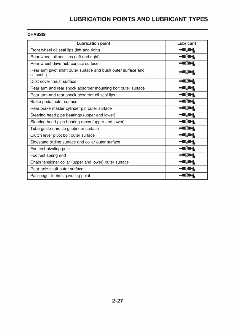
Lubrication point Lubricant
Front wheel oil seal lips (left and right)
Rear wheel oil seal lips (left and right)
Rear wheel drive hub contact surface
Rear arm pivot shaft outer surface and bush outer surface andoil seal lip
Dust cover thrust surface
Rear arm and rear shock absorber mounting bolt outer surface
Rear arm and rear shock absorber oil seal lips
Brake pedal outer surface
Rear brake master cylinder pin outer surface
Steering head pipe bearings (upper and lower)
Steering head pipe bearing races (upper and lower)
Tube guide (throttle grip)inner surface
Clutch lever pivot bolt outer surface
Sidestand sliding surface and collar outer surface
Footrest pivoting point
Footrest spring end
Chain tensioner collar (upper and lower) outer surface
Rear axle shaft outer surface
Passenger footrest pivoting point
CHASSIS
8/12/2019 Yamaha Tenere XT660Z Service Manual
http://slidepdf.com/reader/full/yamaha-tenere-xt660z-service-manual 52/398
COOLING SYSTEM DIAGRAMS
EAS00033
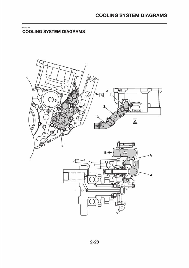
COOLING SYSTEM DIAGRAMS
5VK
5VK00
A
3
2
1
2
3
1
A
A
A
8/12/2019 Yamaha Tenere XT660Z Service Manual
http://slidepdf.com/reader/full/yamaha-tenere-xt660z-service-manual 53/398
COOLING SYSTEM DIAGRAMS
1. Water jacket joint
2. Water pump outlet hose
3. Water pump outlet pipe4. Water pump
A. From the radiator
B. To the cylinder
8/12/2019 Yamaha Tenere XT660Z Service Manual
http://slidepdf.com/reader/full/yamaha-tenere-xt660z-service-manual 54/398
COOLING SYSTEM DIAGRAMS
8/12/2019 Yamaha Tenere XT660Z Service Manual
http://slidepdf.com/reader/full/yamaha-tenere-xt660z-service-manual 55/398
COOLING SYSTEM DIAGRAMS
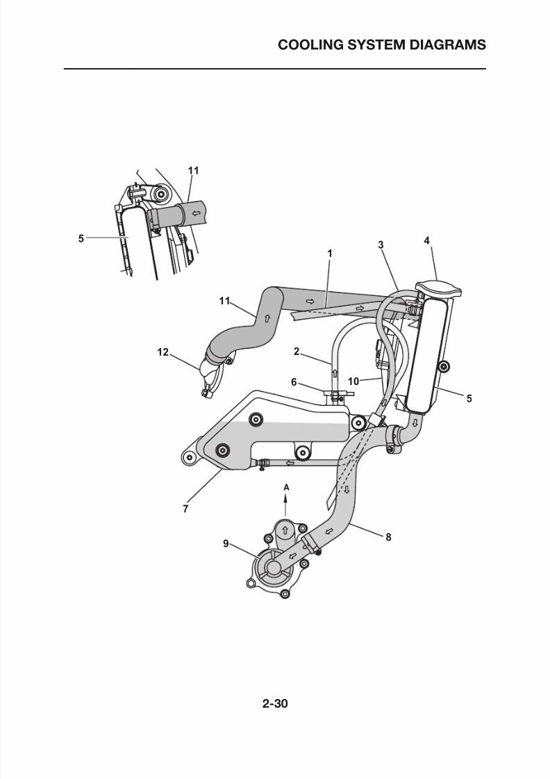
1. Fast idle plunger outlet hose
2. Coolant reservoir hose
3. Coolant reservoir breather hose4. Radiator cap
5. Radiator
6. Coolant reservoir cap
7. Coolant reservoir
8. Radiator outlet hose
9. Water pump
10. Radiator fan
11. Radiator inlet hose
12. Thermostat
A. To the cylinder
8/12/2019 Yamaha Tenere XT660Z Service Manual
http://slidepdf.com/reader/full/yamaha-tenere-xt660z-service-manual 56/398
LUBRICATION CHART
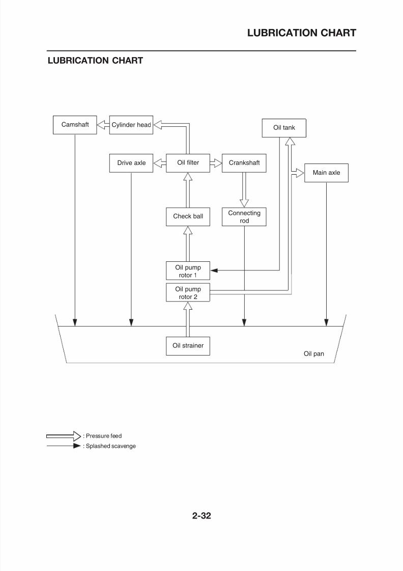
LUBRICATION CHART
Oil pump
rotor 2
Check ball
Oil filter
Cylinder head
Drive axle Crankshaft
Camshaft Oil tank
Main axle
Oil pump
rotor 1
Connectingrod
8/12/2019 Yamaha Tenere XT660Z Service Manual
http://slidepdf.com/reader/full/yamaha-tenere-xt660z-service-manual 57/398
LUBRICATION DIAGRAMS
LUBRICATION DIAGRAMS
8/12/2019 Yamaha Tenere XT660Z Service Manual
http://slidepdf.com/reader/full/yamaha-tenere-xt660z-service-manual 58/398
LUBRICATION DIAGRAMS
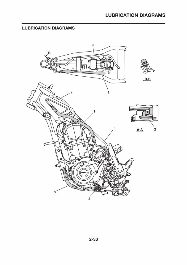
1. Oil delivery hose 2
2. Oil strainer
3. Oil delivery hose 14. Oil tank
5. Breather hose
8/12/2019 Yamaha Tenere XT660Z Service Manual
http://slidepdf.com/reader/full/yamaha-tenere-xt660z-service-manual 59/398
LUBRICATION DIAGRAMS
A-A
A
3
1
2
8/12/2019 Yamaha Tenere XT660Z Service Manual
http://slidepdf.com/reader/full/yamaha-tenere-xt660z-service-manual 60/398
LUBRICATION DIAGRAMS
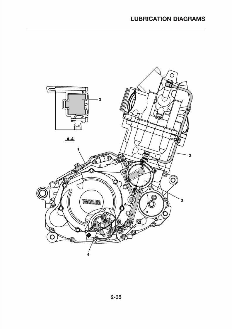
1. Oil delivery pipe 2
2. Oil delivery pipe 1
3. Oil filter4. Oil pump
8/12/2019 Yamaha Tenere XT660Z Service Manual
http://slidepdf.com/reader/full/yamaha-tenere-xt660z-service-manual 61/398
LUBRICATION DIAGRAMS
1
7
2 3A
8/12/2019 Yamaha Tenere XT660Z Service Manual
http://slidepdf.com/reader/full/yamaha-tenere-xt660z-service-manual 62/398
LUBRICATION DIAGRAMS
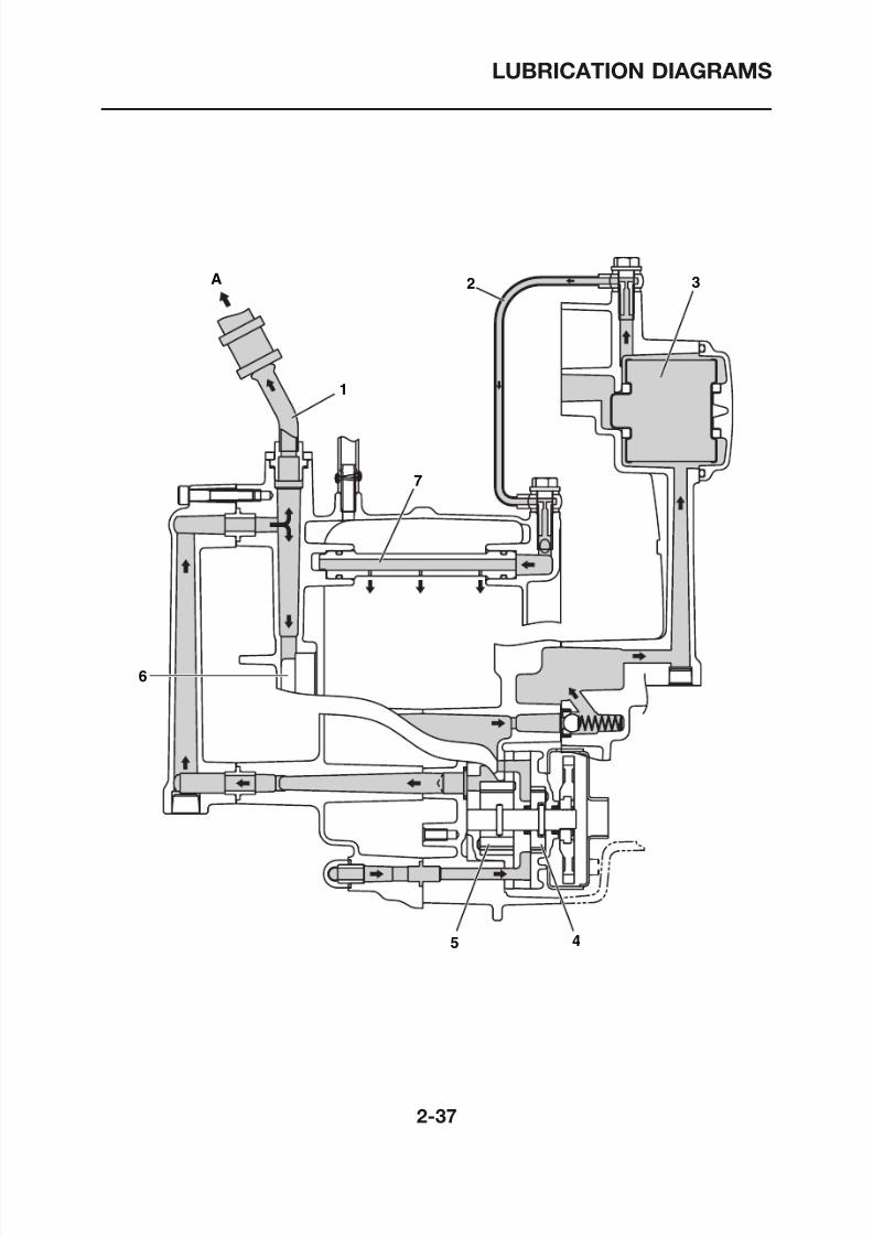
1. Oil delivery hose 2
2. Oil delivery pipe 2
3. Oil filter4. Oil pump rotor 1
5. Oil pump rotor 2
6. Main axle
7. Oil delivery pipe 3
A. To oil tank
8/12/2019 Yamaha Tenere XT660Z Service Manual
http://slidepdf.com/reader/full/yamaha-tenere-xt660z-service-manual 63/398
LUBRICATION DIAGRAMS
1
6
3
2
8/12/2019 Yamaha Tenere XT660Z Service Manual
http://slidepdf.com/reader/full/yamaha-tenere-xt660z-service-manual 64/398
LUBRICATION DIAGRAMS
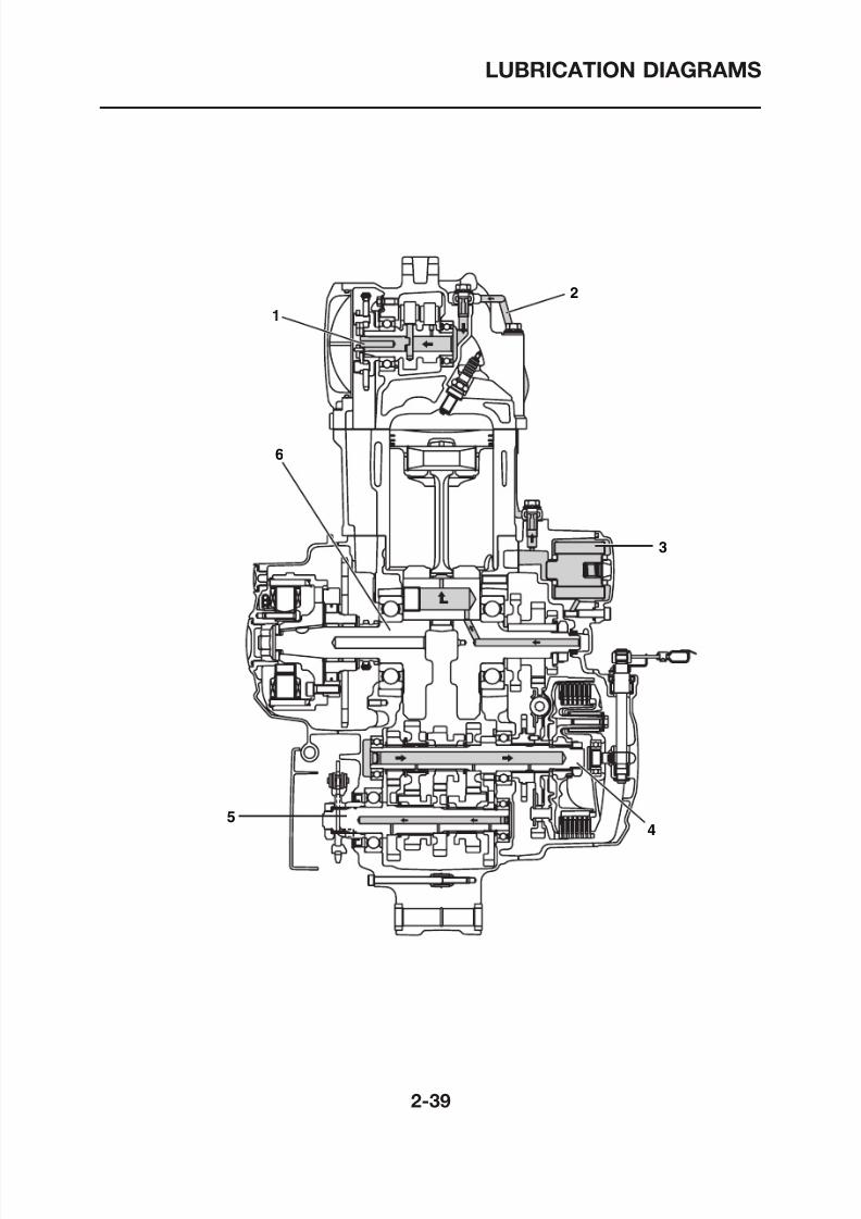
1. Camshaft
2. Oil delivery pipe 1
3. Oil filter4. Main axle
5. Drive axle
6. Crankshaft
8/12/2019 Yamaha Tenere XT660Z Service Manual
http://slidepdf.com/reader/full/yamaha-tenere-xt660z-service-manual 65/398
CABLE ROUTING
CABLE ROUTING
8/12/2019 Yamaha Tenere XT660Z Service Manual
http://slidepdf.com/reader/full/yamaha-tenere-xt660z-service-manual 66/398
CABLE ROUTING
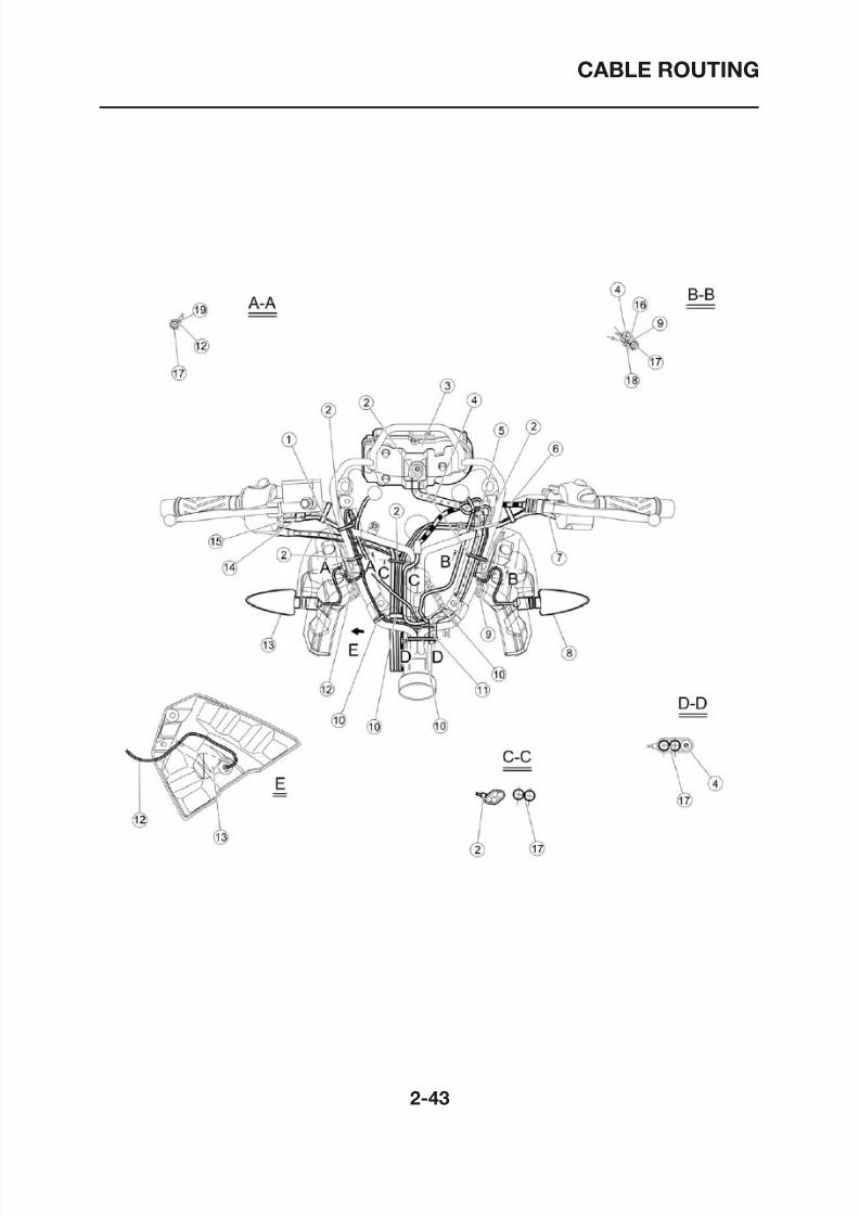
WARNING
Proper cable and lead routing are essential to insure
safe motorcycle operation.
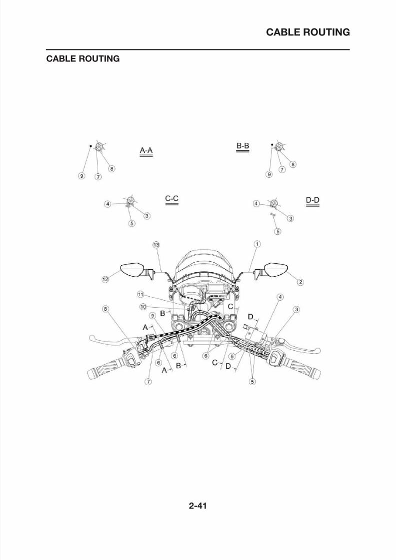
1. Front flasher light lead wire (R)
2. Front flasher (R)
3. Switch handle lead (R)
4. Front brake light switch lead
5. Throttle cables
6. Clamp
7. Clutch switch lead
8. Switch handle lead (L)
9. Clutch cable10. To headlight assembly
11. Speed meter assembly
12. Front flasher (L)
13. Front flasher light lead wire (L)
8/12/2019 Yamaha Tenere XT660Z Service Manual
http://slidepdf.com/reader/full/yamaha-tenere-xt660z-service-manual 67/398
CABLE ROUTING
8/12/2019 Yamaha Tenere XT660Z Service Manual
http://slidepdf.com/reader/full/yamaha-tenere-xt660z-service-manual 68/398
CABLE ROUTING
1. Throttle cables
2. Clamp
3. Speed meter assembly
4. Speed meter cable
5. To speed meter cable
6. Clutch cable
7. Switch handle lead (L)
8. Front flasher (L)
9. Front flasher light lead wire (L)
10.Clamp
11. To wire harness
12. Front flasher light lead wire (R)
13. Front flasher (R)14. Front brake light switch lead
15. Switch handle lead (R)
16.High beam
17.Stay 1
18. Auxiliary light
19. Wire harness flasher light
8/12/2019 Yamaha Tenere XT660Z Service Manual
http://slidepdf.com/reader/full/yamaha-tenere-xt660z-service-manual 69/398
CABLE ROUTING
8/12/2019 Yamaha Tenere XT660Z Service Manual
http://slidepdf.com/reader/full/yamaha-tenere-xt660z-service-manual 70/398
CABLE ROUTING
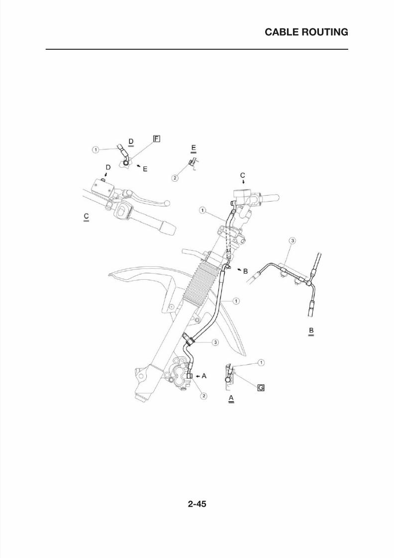
1. Front brake hose
2. Bolt union
3. Front brake hose holder
[F] Stop the turning of brake hose end by this boss.
[G] Stop the turning of brake hose end by this surface.
8/12/2019 Yamaha Tenere XT660Z Service Manual
http://slidepdf.com/reader/full/yamaha-tenere-xt660z-service-manual 71/398
CABLE ROUTING
8/12/2019 Yamaha Tenere XT660Z Service Manual
http://slidepdf.com/reader/full/yamaha-tenere-xt660z-service-manual 72/398
CABLE ROUTING
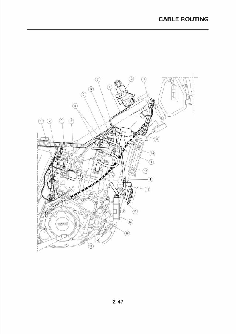
1. Clamp
2. Throttle Position System lead
3. Water temperature sensor lead
4. Ignition coil lead
5. Ignition coil
6. Air Induction System lead wire
7. Air Induction System lead
8. Main switch lead
9. Main switch
10.Clutch wire
11. Spark plug lead
12.Horn lead
13. Horn
14. Rectifier/regulator
15.A.C.magneto lead
16. Neutral switch wire
17. Side stand switch lead
8/12/2019 Yamaha Tenere XT660Z Service Manual
http://slidepdf.com/reader/full/yamaha-tenere-xt660z-service-manual 73/398
CABLE ROUTING
8/12/2019 Yamaha Tenere XT660Z Service Manual
http://slidepdf.com/reader/full/yamaha-tenere-xt660z-service-manual 74/398
CABLE ROUTING
1. Wire plus lead
2. Starter motor lead
3. Wire harness
4. ECU
5. Clamp
6. Wire minus lead
7. Speed sensor lead
8. Rear stop switch
9. Radiator fan motor relay
10. Rear stop switch lead
11. Headlight relay
12.Battery box
13. Starter relay
14. Lean angle cut-off switch
15. Fuel injection diagnostic connector
16. Anti-theft alarm coupler
8/12/2019 Yamaha Tenere XT660Z Service Manual
http://slidepdf.com/reader/full/yamaha-tenere-xt660z-service-manual 75/398
CABLE ROUTING
8/12/2019 Yamaha Tenere XT660Z Service Manual
http://slidepdf.com/reader/full/yamaha-tenere-xt660z-service-manual 76/398
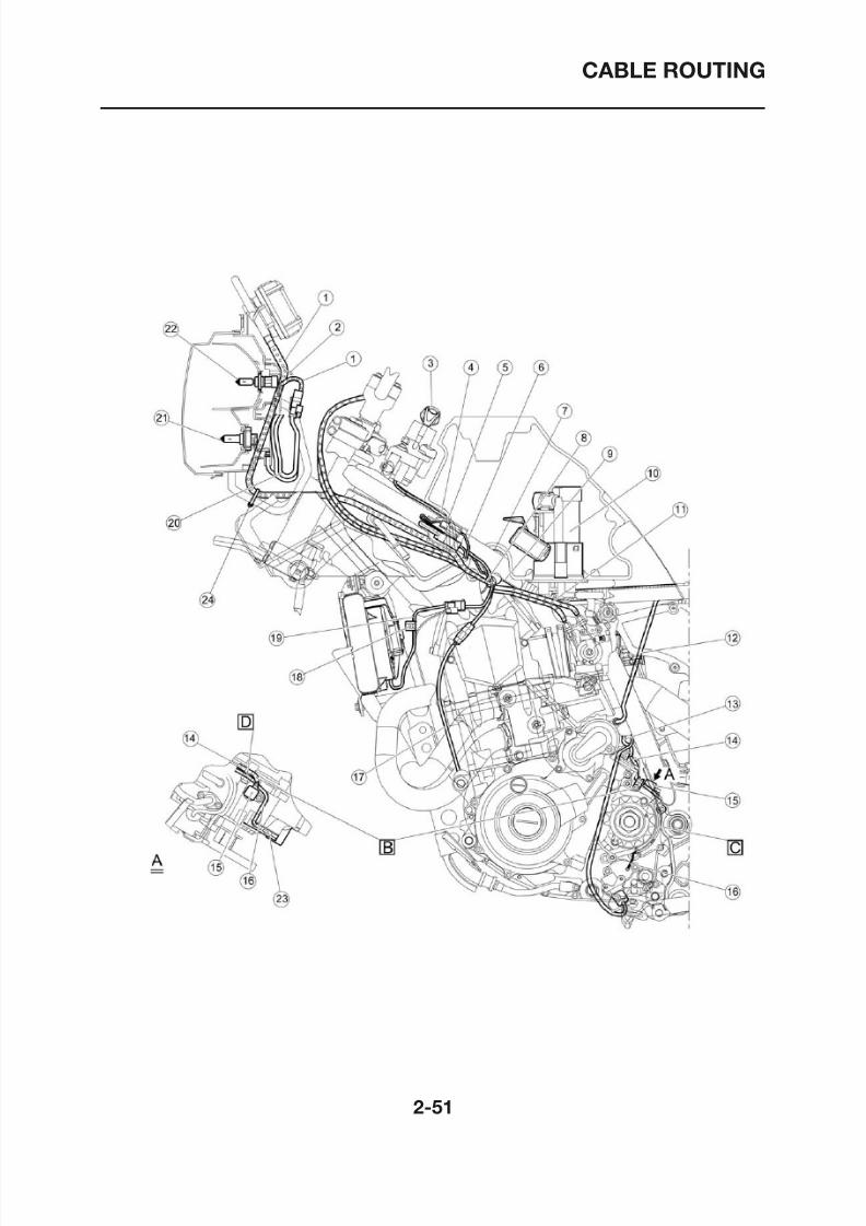
CABLE ROUTING
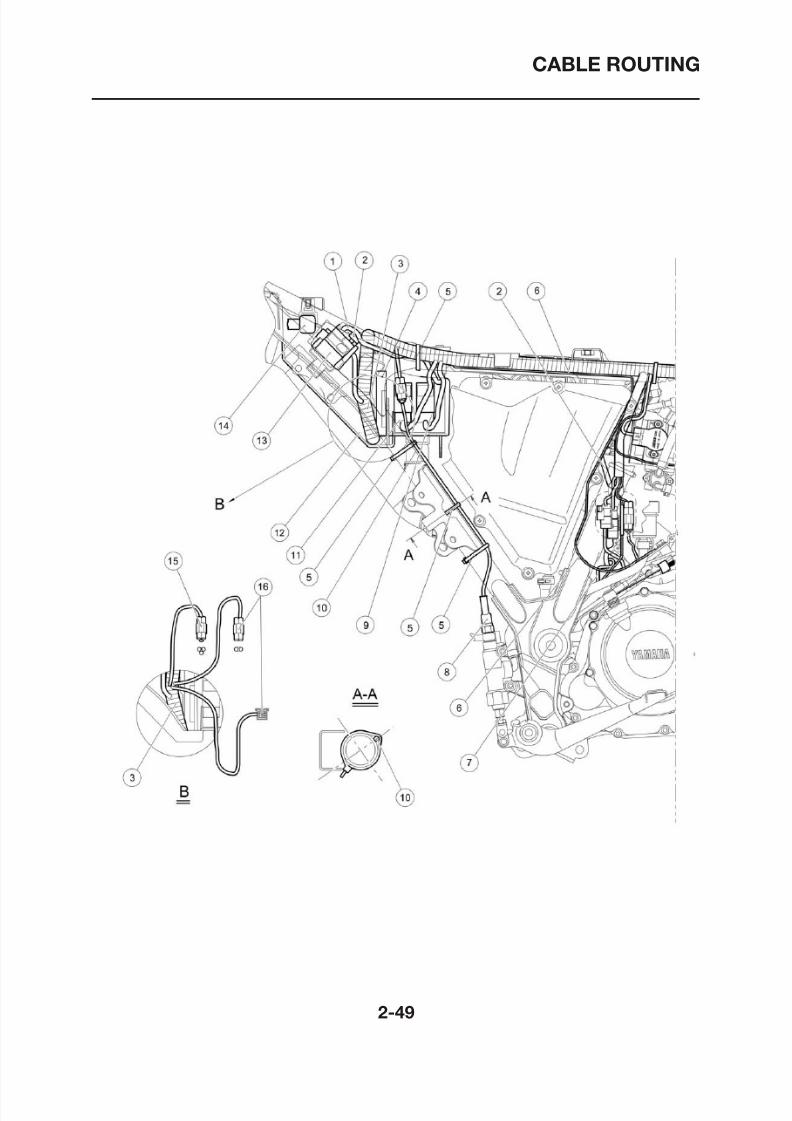
1. Speed meter cable
2. To front flasher
3. Main switch
4. Immobilizer lead
5. Clamp
6. Immobilizer lead
7. Clamp
8. Clamp
9. Speed sensor lead
10.Fuel pump
11. Throttle wire
12. Starter motor lead
13.A.C.magneto lead wire
14. Speed sensor lead
15. Speed sensor
16. Neutral switch lead wire
17. Sonda Lambda wire
18.Clamp
19. Fun motor lead
20. Auxiliary light lead
21.High beam
22.Low beam
23.Cover
24.Clamp
[B] Put speed sensor lead and neutral switch lead wire
passing through the clamp.
[C] Put neutral switch lead wire under cover.
[D] Neutral switch lead wire shall be under speed sensor
lead
8/12/2019 Yamaha Tenere XT660Z Service Manual
http://slidepdf.com/reader/full/yamaha-tenere-xt660z-service-manual 77/398
CABLE ROUTING
8/12/2019 Yamaha Tenere XT660Z Service Manual
http://slidepdf.com/reader/full/yamaha-tenere-xt660z-service-manual 78/398
CABLE ROUTING
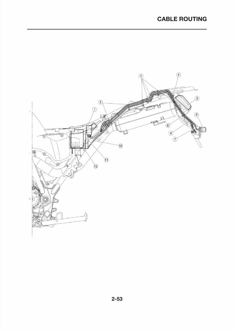
1. Fuse box
2. Clamp
3. Clamp
4. Clamp
5. Tail light
6. License light
7. License light lead wire
8. Clamp
9. Rear flasher light lead wire
10.Battery box
11. ECU
12.Battery
CABLE ROUTING
8/12/2019 Yamaha Tenere XT660Z Service Manual
http://slidepdf.com/reader/full/yamaha-tenere-xt660z-service-manual 79/398
CABLE ROUTING
CABLE ROUTING
8/12/2019 Yamaha Tenere XT660Z Service Manual
http://slidepdf.com/reader/full/yamaha-tenere-xt660z-service-manual 80/398
CABLE ROUTING
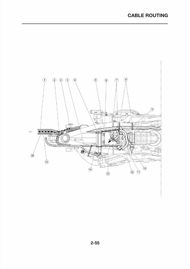
1. Switch handle lead (R)/Front stop switch lead2. Clamp3. Throttle wire
4. Clamp5. Wire harness6. Speed sensor lead7. Fuel pump lead8. Clamp9. Fuel hose10. Air temperature sensor11. Fuel injector lead12. Fuel injector13. To fuel tank14.Clamp
15.Clutch wire16. Switch handle lead (L)
CABLE ROUTING
8/12/2019 Yamaha Tenere XT660Z Service Manual
http://slidepdf.com/reader/full/yamaha-tenere-xt660z-service-manual 81/398
CABLE ROUTING
CABLE ROUTING
8/12/2019 Yamaha Tenere XT660Z Service Manual
http://slidepdf.com/reader/full/yamaha-tenere-xt660z-service-manual 82/398
CABLE ROUTING
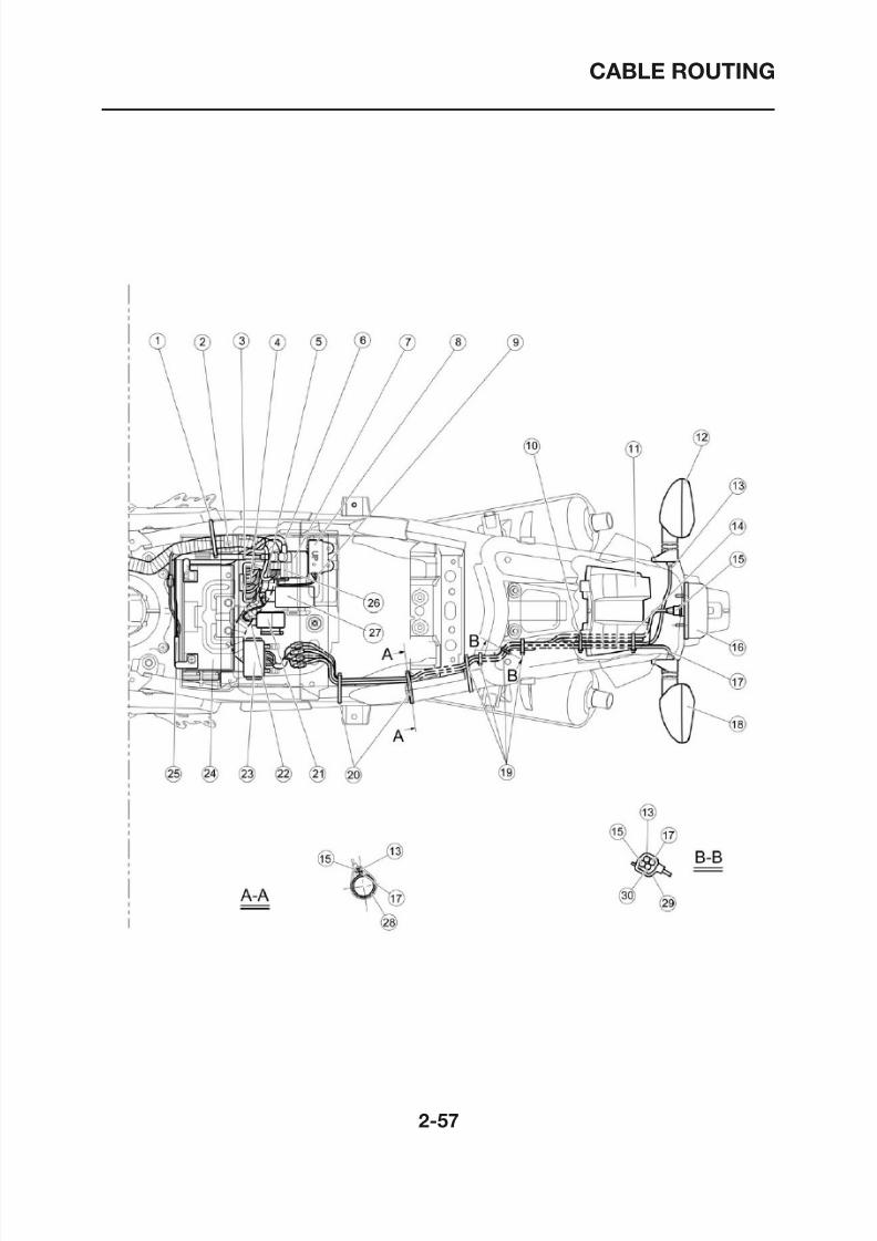
1. Clamp2. Start wire harness installation3. Starter motor lead
4. ECU lead5. Starter relay fuse6. Wire plus lead7. Starter relay8. Lean angle cut-off switch9. Lean angle cut-off switch lead wire10.Clamp11. Tail light12. Rear flasher (R)13. Rear flasher light lead wire (R)14.Clamp
15. License light lead wire16. License light17. Rear flasher light lead wire (L)18. Rear flasher (L)19.Clamp20.Clamp21. Flasher relay22. Starter motor lead23. Fuse box24.Battery25. Wire minus lead (from battery)
26. Main fuse spare27. Relay unit28.Frame29. Reinforcement compl.30. Tail light lead wire
CABLE ROUTING
8/12/2019 Yamaha Tenere XT660Z Service Manual
http://slidepdf.com/reader/full/yamaha-tenere-xt660z-service-manual 83/398
CABLE ROUTING
CABLE ROUTING
8/12/2019 Yamaha Tenere XT660Z Service Manual
http://slidepdf.com/reader/full/yamaha-tenere-xt660z-service-manual 84/398
CABLE ROUTING
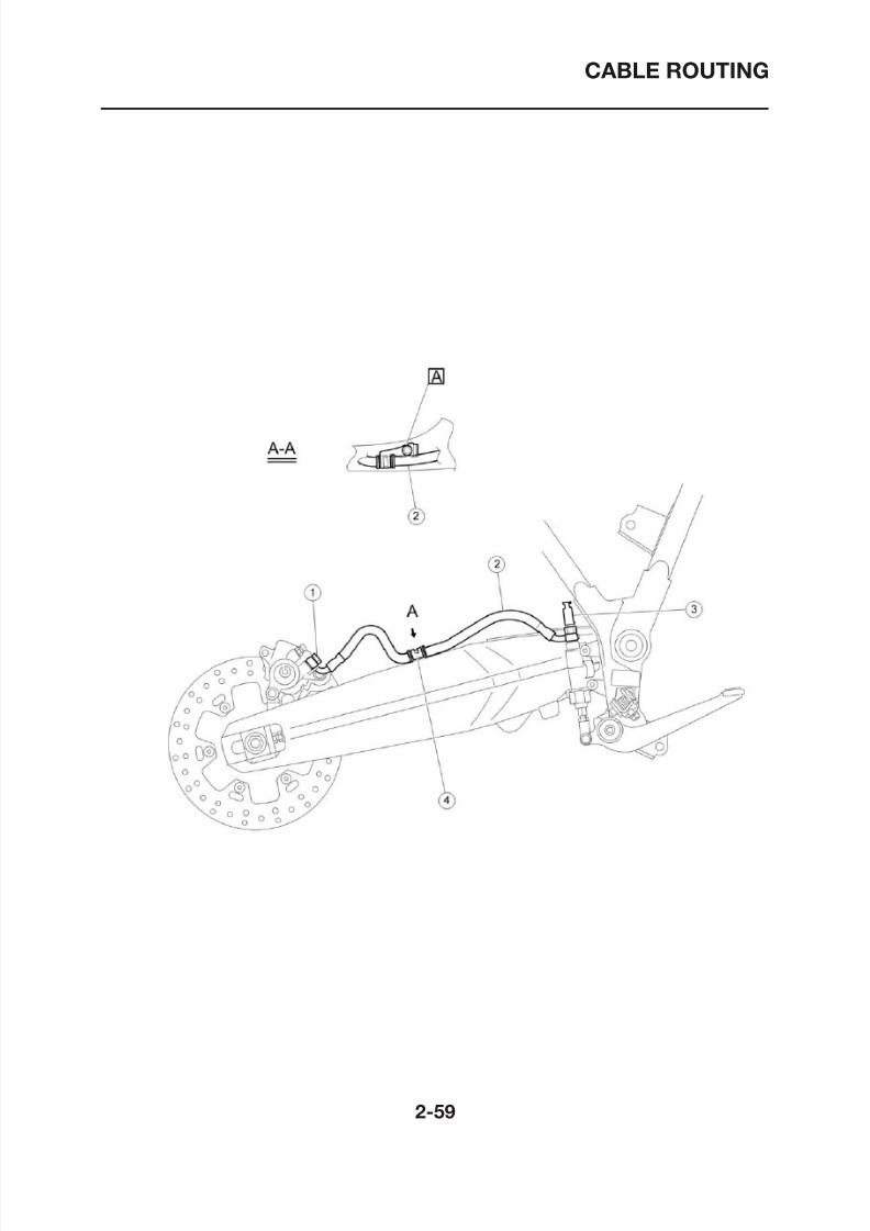
1. Bolt union2. Brake hose3. Rear stop switch
4. Clamp hose
[A] Add Loctite® 243

8/12/2019 Yamaha Tenere XT660Z Service Manual
http://slidepdf.com/reader/full/yamaha-tenere-xt660z-service-manual 85/398
PERIODIC CHECKS AND ADJUSTMENTS
PERIODIC MAINTENANCE .......................................................................... 3-1
INTRODUCTION ...................................................................................... 3-1
PERIODIC MAINTENANCE AND LUBRICATION CHART...................... 3-1
ENGINE........................................................................................................... 3-3
ADJUSTING THE VALVE CLEARANCE .................................................. 3-3
ADJUSTING THE ENGINE IDLING SPEED............................................ 3-5
ADJUSTING THE THROTTLE CABLE FREE PLAY ................................ 3-5
CHECKING THE SPARK PLUG............................................................... 3-6
CHECKING THE IGNITION TIMING ........................................................ 3-7
MEASURING THE COMPRESSION PRESSURE................................... 3-8
CHECKING THE ENGINE OIL LEVEL..................................................... 3-9
CHANGING THE ENGINE OIL.................................................................3-10
ADJUSTING THE CLUTCH CABLE FREE PLAY ....................................3-11
REPLACING THE AIR FILTER ELEMENTAND CLEANING THE CHECK HOSE......................................................3-12
CHECKING THE THROTTLE BODY JOINT.............................................3-13
CHECKING THE FUEL HOSE .................................................................3-13
CHECKING THE FUEL TANK BREATHER HOSE...................................3-13
CHECKING THE CRANKCASE BREATHER HOSES .............................3-13
CHECKING THE EXHAUST SYSTEM.....................................................3-14
CHECKING THE COOLANT LEVEL........................................................3-14
CHECKING THE COOLING SYSTEM .....................................................3-15CHANGING THE COOLANT....................................................................3-16
3
8/12/2019 Yamaha Tenere XT660Z Service Manual
http://slidepdf.com/reader/full/yamaha-tenere-xt660z-service-manual 86/398
LUBRICATING THE SIDESTAND.............................................................3-28
LUBRICATING THE REAR SUSPENSION ..............................................3-29
LUBRICATING THE SWINGARM PIVOTS...............................................3-29
ELECTRICAL SYSTEM..................................................................................3-30CHECKING AND CHARGING THE BATTERY ........................................3-30CHECKING THE FUSES..........................................................................3-30REPLACING THE HEADLIGHT BULB.....................................................3-30REPLACING AN AUXILIARY LIGHT BULB .............................................3-31TAIL/BRAKE LIGHT..................................................................................3-31
REPLACING A TURN SIGNAL LIGHT BULB ..........................................3-32REPLACING THE LICENSE PLATE LIGHT BULB ..................................3-32ADJUSTING THE HEADLIGHT BEAM ....................................................3-32
PERIODIC MAINTENANCE
8/12/2019 Yamaha Tenere XT660Z Service Manual
http://slidepdf.com/reader/full/yamaha-tenere-xt660z-service-manual 87/398
PERIODIC MAINTENANCE
PERIODIC MAINTENANCE
EAS00036
INTRODUCTION
This chapter includes all information necessary to perform recommended checks and adjustments.If followed, these preventive maintenance procedures will ensure more reliable vehicle operation, alonger service life and reduce the need for costly overhaul work. This information applies to vehiclesalready in service as well as to new vehicles that are being prepared for sale. All service techniciansshould be familiar with this entire chapter.
EAS00037
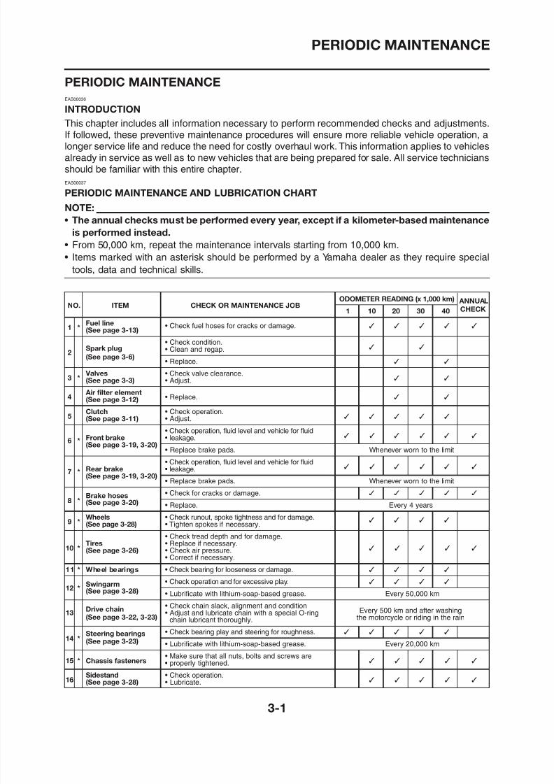
PERIODIC MAINTENANCE AND LUBRICATION CHART
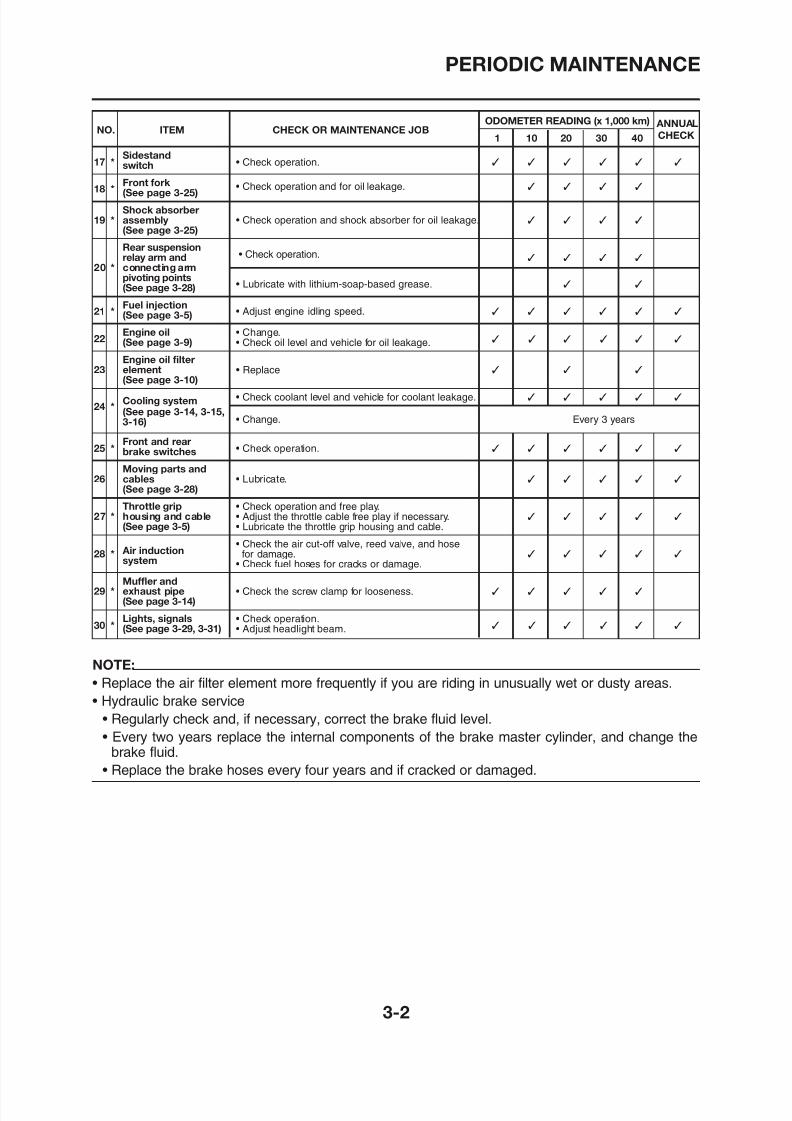
NOTE:
• The annual checks must be performed every year, except if a kilometer-based maintenance
is performed instead.
• From 50,000 km, repeat the maintenance intervals starting from 10,000 km.
• Items marked with an asterisk should be performed by a Yamaha dealer as they require special
tools, data and technical skills.
ODOMETER READING (x 1,000 km) ANNUALNO. ITEM CHECK OR MAINTENANCE JOB1 10 20 30 40 CHECK
1 *Fuel line(See page 3-13)
• Check fuel hoses for cracks or damage.
• Check condition.
2Spark plug • Clean and regap.(See page 3-6)
• Replace.
3 * Valves • Check valve clearance.
(See page 3-3) • Adjust.
4 Air filter element
• Replace. (See page 3-12)
5Clutch • Check operation.
PERIODIC MAINTENANCE
8/12/2019 Yamaha Tenere XT660Z Service Manual
http://slidepdf.com/reader/full/yamaha-tenere-xt660z-service-manual 88/398
PERIODIC MAINTENANCE
ODOMETER READING (x 1,000 km) ANNUALNO. ITEM CHECK OR MAINTENANCE JOB
1 10 20 30 40 CHECK
17 *Sidestand
• Check operation. switch
18 *Front fork(See page 3-25)
• Check operation and for oil leakage.
Shock absorber19 * assembly • Check operation and shock absorber for oil leakage.
(See page 3-25)
Rear suspension• Check operation.relay arm and
20 * connecting armpivoting points
• Lubricate with lithium-soap-based grease.
(See page 3-28)
21 *Fuel injection
• Adjust engine idling speed. (See page 3-5)
22Engine oil • Change.
(See page 3-9) • Check oil level and vehicle for oil leakage.
Engine oil filter23 element • Replace
(See page 3-10)
24 *Cooling system • Check coolant level and vehicle for coolant leakage.
(See page 3-14, 3-15,3-16) • Change. Every 3 years
25 *Front and rear
• Check operation. brake switches
Moving parts and26 cables • Lubricate.
(See page 3-28)
Throttle grip • Check operation and free play.27 * housing and cable • Adjust the throttle cable free play if necessary.
(See page 3-5) • Lubricate the throttle grip housing and cable.
Air induction• Check the air cut-off valve, reed valve, and hose
28 *system
for damage.
• Check fuel hoses for cracks or damage.Muffler and
29 * exhaust pipe • Check the screw clamp for looseness.
ENGINE
8/12/2019 Yamaha Tenere XT660Z Service Manual
http://slidepdf.com/reader/full/yamaha-tenere-xt660z-service-manual 89/398
ENGINE
ENGINE
EAS00049
ADJUSTING THE VALVE CLEARANCE
The following procedure applies to all of thevalves.
NOTE:
• Valve clearance adjustment should be madeon a cold engine, at room temperature.
• When the valve clearance is to be measured
or adjusted, the piston must be at top deadcenter (TDC) on the compression stroke.
1. Remove:• Seat
Refer to “GENERAL CHASSIS” on page4-1.
• Fuel tank
Refer to “FUEL TANK” on page 7-1.• RadiatorRefer to “RADIATOR” on page 6-1.
• Air-filter-to-air-cut-off-valve hoseRefer to “AIR INDUCTION SYSTEM” onpage 7-11.
2. Remove:• Intake tappet cover• Exhaust tappet cover “1”
• Camshaft sprocket cover “2”
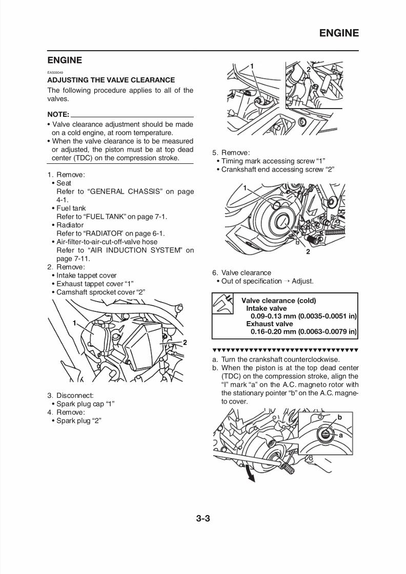
5. Remove:• Timing mark accessing screw “1”• Crankshaft end accessing screw “2”
6. Valve clearance• Out of specification → Adjust.
12
Valve clearance (cold)
ENGINE
8/12/2019 Yamaha Tenere XT660Z Service Manual
http://slidepdf.com/reader/full/yamaha-tenere-xt660z-service-manual 90/398
ENGINE
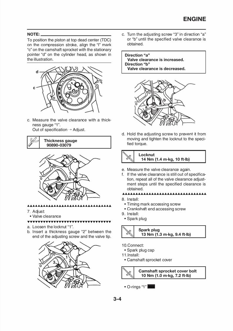
NOTE:
To position the piston at top dead center (TDC)
on the compression stroke, align the “I” mark“c” on the camshaft sprocket with the stationarypointer “d” on the cylinder head, as shown inthe illustration.
c. Measure the valve clearance with a thick-
ness gauge “1”.Out of specification → Adjust.
d
c
Thickness gauge90890-03079
1
c. Turn the adjusting screw “3” in direction “a”or “b” until the specified valve clearance is
obtained.
Direction “a” Valve clearance is increased.
Direction “b” Valve clearance is decreased.
d. Hold the adjusting screw to prevent it frommoving and tighten the locknut to the speci-fied torque.
a
b
e. Measure the valve clearance again.f. If the valve clearance is still out of specifica-
Locknut14 Nm (1.4 m·kg, 10 ft·lb)
ENGINE
8/12/2019 Yamaha Tenere XT660Z Service Manual
http://slidepdf.com/reader/full/yamaha-tenere-xt660z-service-manual 91/398
ENGINE
Intake tappet cover bolt10 Nm (1.0 m·kg, 7.2 ft·lb)
Exhaust tappet cover bolt10 Nm (1.0 m·kg, 7.2 ft·lb)
• Intake tappet cover
New 1
• Exhaust tappet cover
12.Install:• Air-filter-to-air-cut-off-valve hose
Refer to “AIR INDUCTION SYSTEM” onpage 7-11.
• RadiatorRefer to “RADIATOR” on page 6-1.
• Fuel tankRefer to “FUEL TANK” on page 7-1.
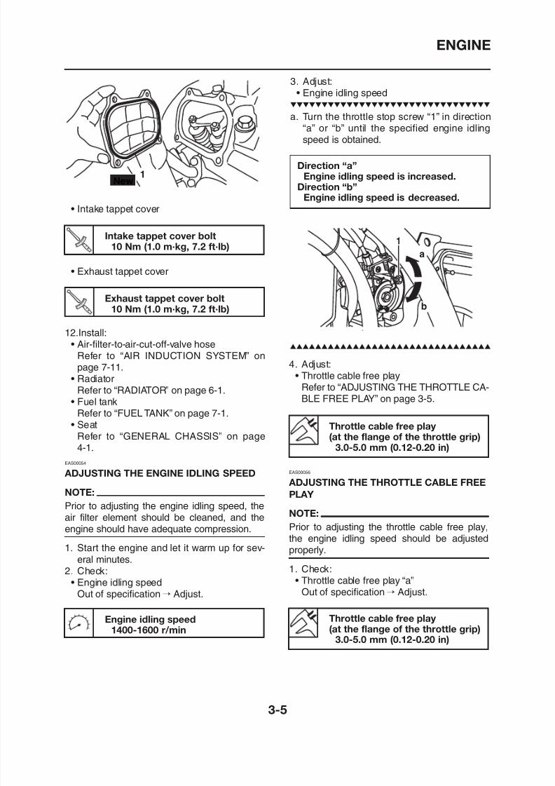
Direction “a”Engine idling speed is increased.
Direction “b”Engine idling speed is decreased.
3. Adjust:• Engine idling speed
a. Turn the throttle stop screw “1” in direction“a” or “b” until the specified engine idlingspeed is obtained.
4. Adjust:• Throttle cable free play
Refer to “ADJUSTING THE THROTTLE CA-
BLE FREE PLAY” on page 3-5.
ENGINE
8/12/2019 Yamaha Tenere XT660Z Service Manual
http://slidepdf.com/reader/full/yamaha-tenere-xt660z-service-manual 92/398
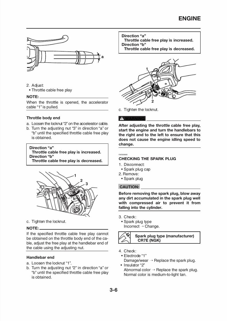
ENGINE
Throttle body end
a. Loosen the locknut “2”on the accelerator cable.b. Turn the adjusting nut “3” in direction “a” or
“b” until the specified throttle cable free playis obtained.
Direction “a”Throttle cable free play is increased.
Direction “b”Throttle cable free play is decreased.
c. Tighten the locknut.
WARNING
After adjusting the throttle cable free play,
start the engine and turn the handlebars to
the right and to the left to ensure that this
does not cause the engine idling speed to
change.
EAS00060
CHECKING THE SPARK PLUG
1. Disconnect:• Spark plug cap
2
1
b
a
Direction “a”Throttle cable free play is increased.
Direction “b”
Throttle cable free play is decreased.
2. Adjust:• Throttle cable free play
NOTE:
When the throttle is opened, the acceleratorcable “1” is pulled.
a
ENGINE
8/12/2019 Yamaha Tenere XT660Z Service Manual
http://slidepdf.com/reader/full/yamaha-tenere-xt660z-service-manual 93/398
ENGINE
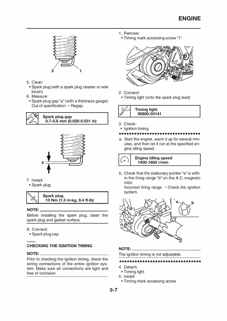
5. Clean:• Spark plug (with a spark plug cleaner or wirebrush)
6. Measure:• Spark plug gap “a” (with a thickness gauge)
Out of specification → Regap.
Spark plug gap
0.7-0.8 mm (0.028-0.031 in)
a. Start the engine, warm it up for several min-utes, and then let it run at the specified en-gine idling speed.
1. Remove:• Timing mark accessing screw “1”
2. Connect:• Timing light (onto the spark plug lead)
3. Check:• Ignition timing
Timing light90890-03141
Engine idling speed
1400-1600 r/min
ENGINE
8/12/2019 Yamaha Tenere XT660Z Service Manual
http://slidepdf.com/reader/full/yamaha-tenere-xt660z-service-manual 94/398
ENGINE
EAS00067
MEASURING THE COMPRESSION
PRESSURE
NOTE:
Insufficient compression pressure will result ina loss of performance.
1. Measure:• Valve clearance
Out of specification → Adjust.
Refer to “ADJUSTING THE VALVE CLEAR-ANCE” on page 3-3.
2. Start the engine, warm it up for several min-utes, and then turn it off.
3. Disconnect:• Spark plug cap
4. Remove:• Spark plug
CAUTION:
Before removing the spark plug, blow away
any dirt accumulated in the spark plug well
with compressed air to prevent it from
falling into the cylinder.
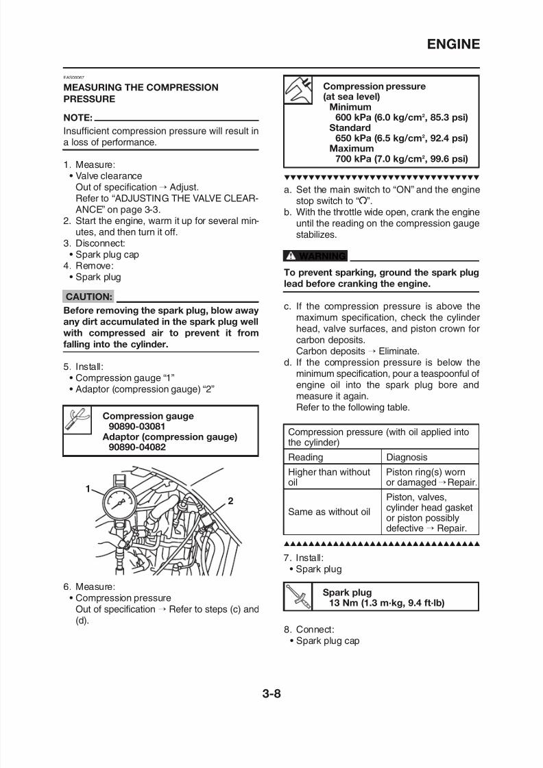
5. Install:• Compression gauge “1”
• Adaptor (compression gauge) “2”
Compression pressure(at sea level)
Minimum600 kPa (6.0 kg/cm2, 85.3 psi)
Standard650 kPa (6.5 kg/cm2, 92.4 psi)
Maximum700 kPa (7.0 kg/cm2, 99.6 psi)
a. Set the main switch to “ON” and the engine
stop switch to “I”.b. With the throttle wide open, crank the engine
until the reading on the compression gaugestabilizes.
WARNING
To prevent sparking, ground the spark plug
lead before cranking the engine.
c. If the compression pressure is above themaximum specification, check the cylinderhead, valve surfaces, and piston crown forcarbon deposits.Carbon deposits → Eliminate.
d. If the compression pressure is below theminimum specification, pour a teaspoonful of
engine oil into the spark plug bore andmeasure it again.Refer to the following table
ENGINE
8/12/2019 Yamaha Tenere XT660Z Service Manual
http://slidepdf.com/reader/full/yamaha-tenere-xt660z-service-manual 95/398
ENGINE
EAS00069
CHECKING THE ENGINE OIL LEVEL
1. Place the vehicle on a level surface and holdit in an upright position.
NOTE:
Make sure that the vehicle is positioned straightup when checking the oil level. A slight tilt to theside can result in a false reading.
2. Start the engine, warm it up for 10-15 min-
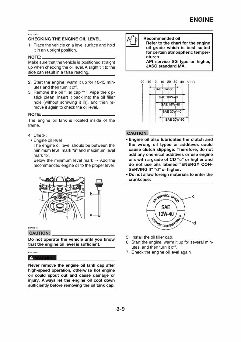
utes and then turn it off.3. Remove the oil filler cap “1”, wipe the dip-stick clean, insert it back into the oil fillerhole (without screwing it in), and then re-move it again to check the oil level.
NOTE:
The engine oil tank is located inside of theframe.
4. Check:• Engine oil level
The engine oil level should be between theminimum level mark “a” and maximum levelmark “b”.Below the minimum level mark → Add therecommended engine oil to the proper level.
Recommended oilRefer to the chart for the engine
oil grade which is best suitedfor certain atmospheric temper-atures. API service SG type or higher,JASO standard MA.
CAUTION:
• Engine oil also lubricates the clutch and
the wrong oil types or additives could
cause clutch slippage. Therefore, do not
add any chemical additives or use engine
oils with a grade of CD “c” or higher and
do not use oils labeled “ENERGY CON-
SERVING II” “d” or higher.
• Do not allow foreign materials to enter thecrankcase.
ENGINE
8/12/2019 Yamaha Tenere XT660Z Service Manual
http://slidepdf.com/reader/full/yamaha-tenere-xt660z-service-manual 96/398
ENGINE
EAS00076
CHANGING THE ENGINE OIL
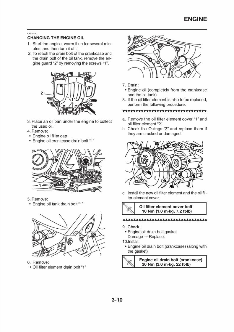
1. Start the engine, warm it up for several min-utes, and then turn it off.2. To reach the drain bolt of the crankcase and
the drain bolt of the oil tank, remove the en-gine guard “2” by removing the screws “1”.
3. Place an oil pan under the engine to collect
the used oil.4. Remove:• Engine oil filler cap• Engine oil crankcase drain bolt “1”
7. Drain:• Engine oil (completely from the crankcaseand the oil tank)
8. If the oil filter element is also to be replaced,perform the following procedure.
a. Remove the oil filter element cover “1” andoil filter element “2”.
b. Check the O-rings “3” and replace them ifthey are cracked or damaged.
2
ENGINE
8/12/2019 Yamaha Tenere XT660Z Service Manual
http://slidepdf.com/reader/full/yamaha-tenere-xt660z-service-manual 97/398
ENGINE
Engine oil drain bolt (oil tank)18 Nm (1.8 m·kg, 12.9 ft·lb)
Oil filter element drain bolt10 Nm (1.0 m·kg, 7.2 ft·lb)
• Engine oil drain bolt (oil tank) (along with thegasket)
• Oil filter element drain bolt
11.Fill:• Oil tank (with the specified amount of the
recommended engine oil)
CAUTION:
The engine oil tank must be filled with
engine oil in two steps. First, fill the engine
oil tank with 1.9 L (1.67 Imp qt, 2.0 US qt) of
the recommended engine oil. Then, startthe engine, race it five or six times, turn it
off, and then add the remainder of the
engine oil.
Quantity Total amount
2.90 L (2.56 Imp qt, 3.06 US qt)
Without oil filter elementreplacement
2 50 L (2 19 I 2 64 US )
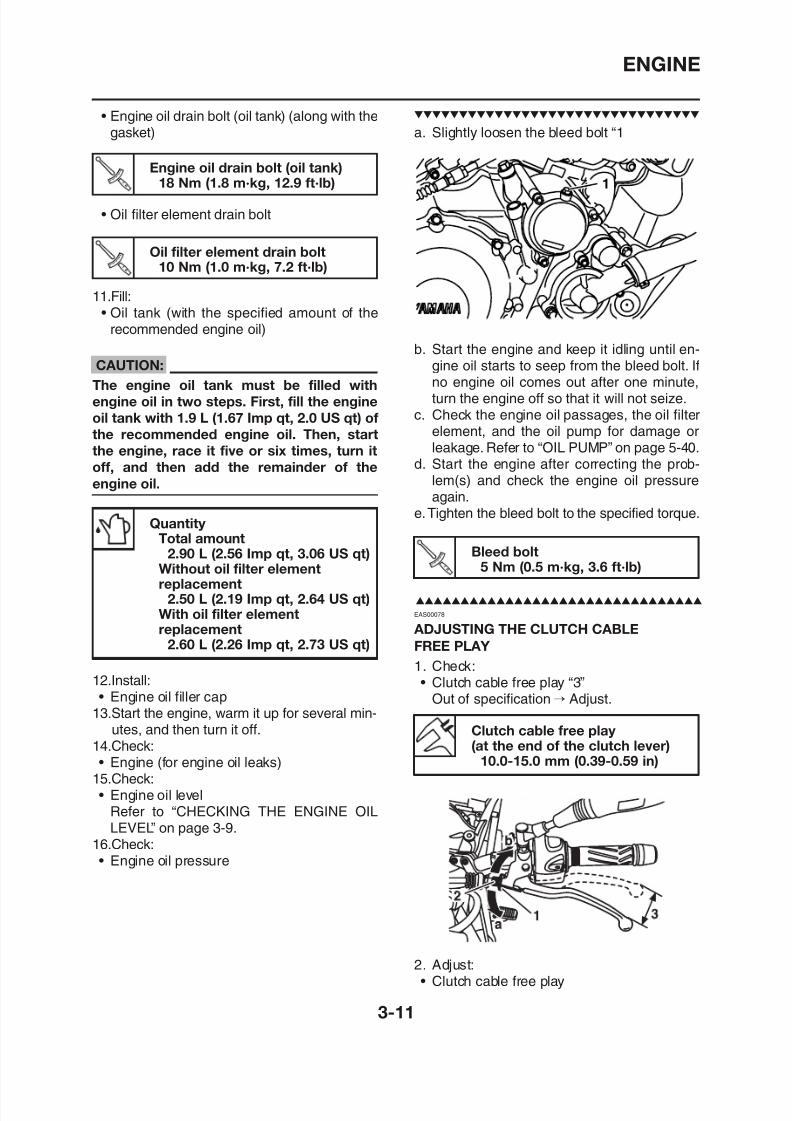
a. Slightly loosen the bleed bolt “1
b. Start the engine and keep it idling until en-gine oil starts to seep from the bleed bolt. Ifno engine oil comes out after one minute,turn the engine off so that it will not seize.
c. Check the engine oil passages, the oil filter
element, and the oil pump for damage orleakage. Refer to “OIL PUMP” on page 5-40.
d. Start the engine after correcting the prob-lem(s) and check the engine oil pressureagain.
e.Tighten the bleed bolt to the specified torque.
1
Bleed bolt
5 Nm (0.5 m·kg, 3.6 ft·lb)
ENGINE
8/12/2019 Yamaha Tenere XT660Z Service Manual
http://slidepdf.com/reader/full/yamaha-tenere-xt660z-service-manual 98/398
ENGINE
Handlebar end
a. Slide back the rubber cover.b. Loosen the locknut “1”.c. Turn the adjusting bolt “2” in direction “a” or
“b” until the specified clutch cable free play isobtained.
d. Tighten the locknut.e. Slide the rubber cover to its original position.
NOTE:
If the specified clutch cable free play cannot beobtained on the handlebar end of the cable, ad-
just the free play at the engine end of the cableusing the adjusting nut.
Engine end
a. Loosen the locknut “1”.b. Turn the adjusting nut “2” in direction “a” or
“b” until the specified clutch cable free play isobtained.
Direction “a”
EAS00086
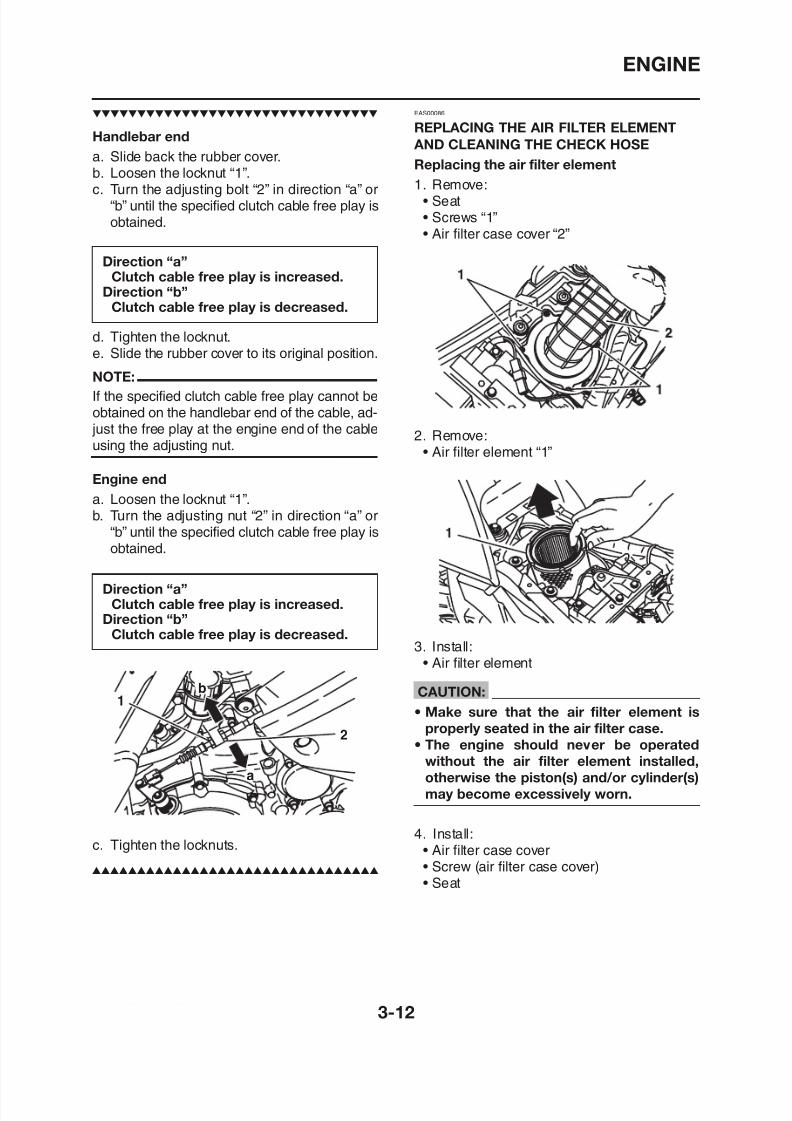
REPLACING THE AIR FILTER ELEMENT
AND CLEANING THE CHECK HOSE
Replacing the air filter element
1. Remove:• Seat• Screws “1”• Air filter case cover “2”
2. Remove:• Air filter element “1”
Direction “a”Clutch cable free play is increased.
Direction “b”Clutch cable free play is decreased.
ENGINE
8/12/2019 Yamaha Tenere XT660Z Service Manual
http://slidepdf.com/reader/full/yamaha-tenere-xt660z-service-manual 99/398
Cleaning the air filter check hose
1. Check:
• Air filter check hose “1”Accumulated dirt or water → Clean.
2. Remove:• Check hose cap “2”
3. Drain:• Any dirt, water or oil
4. Install:• Check hose cap
EAS00094
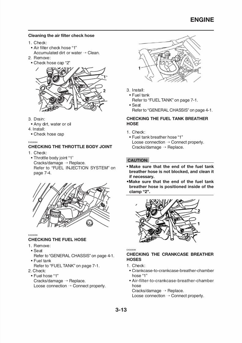
CHECKING THE THROTTLE BODY JOINT
1. Check:• Throttle body joint “1”
Cracks/damage → Replace.Refer to “FUEL INJECTION SYSTEM” on
page 7-4.
3. Install:• Fuel tank
Refer to “FUEL TANK” on page 7-1.• Seat
Refer to “GENERAL CHASSIS” on page 4-1.
CHECKING THE FUEL TANK BREATHER
HOSE
1. Check:• Fuel tank breather hose “1”
Loose connection → Connect properly.Cracks/damage → Replace.
CAUTION:
• Make sure that the end of the fuel tank
breather hose is not blocked, and clean it
if necessary.
•Make sure that the end of the fuel tank
ENGINE
8/12/2019 Yamaha Tenere XT660Z Service Manual
http://slidepdf.com/reader/full/yamaha-tenere-xt660z-service-manual 100/398
CAUTION:Make sure the breather hoses are routed
correctly.
EAS00099
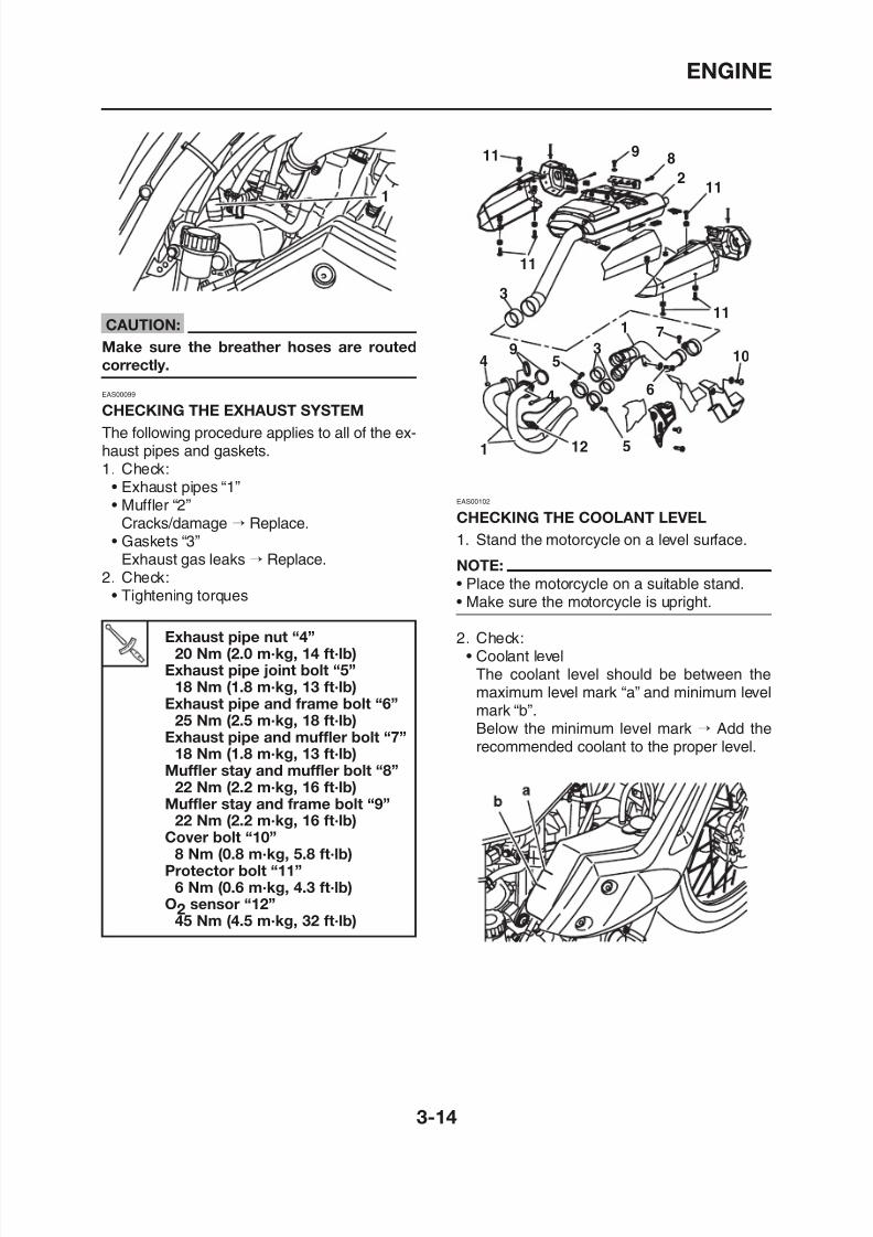
CHECKING THE EXHAUST SYSTEM
The following procedure applies to all of the ex-haust pipes and gaskets.
1. Check:• Exhaust pipes “1”• Muffler “2”
Cracks/damage → Replace.• Gaskets “3”
Exhaust gas leaks → Replace.2. Check:
• Tightening torques
Exhaust pipe nut “4”20 Nm (2 0 m·kg 14 ft·lb)
EAS00102
CHECKING THE COOLANT LEVEL
1. Stand the motorcycle on a level surface.
NOTE:
• Place the motorcycle on a suitable stand.• Make sure the motorcycle is upright.
2. Check:• Coolant level
ENGINE
8/12/2019 Yamaha Tenere XT660Z Service Manual
http://slidepdf.com/reader/full/yamaha-tenere-xt660z-service-manual 101/398
CAUTION:
• Adding water instead of coolant lowers
the antifreeze content of the coolant. Ifwater is used instead of coolant check,
and if necessary, correct the antifreeze
concentration of the coolant.
• Use only distilled water. However, if dis-
tilled water is not available, soft water may
be used.
3. Start the engine, warm it up for several min-utes, and then turn it off.4. Check:
• Coolant level
NOTE:
Before checking the coolant level, wait a fewminutes until it settles.
EAS00104
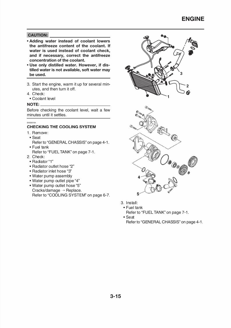
CHECKING THE COOLING SYSTEM
1. Remove:• Seat
Refer to “GENERAL CHASSIS” on page 4-1.• Fuel tank
Refer to “FUEL TANK” on page 7-1.2. Check:
• Radiator “1”
• Radiator outlet hose “2”• Radiator inlet hose “3”
ENGINE
8/12/2019 Yamaha Tenere XT660Z Service Manual
http://slidepdf.com/reader/full/yamaha-tenere-xt660z-service-manual 102/398
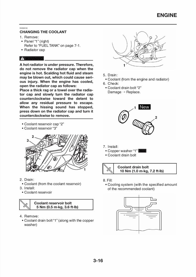
EAS00105
CHANGING THE COOLANT
1. Remove:• Panel “1” (right)Refer to “FUEL TANK” on page 7-1.
• Radiator cap
WARNING
A hot radiator is under pressure. Therefore,
do not remove the radiator cap when the
engine is hot. Scalding hot fluid and steammay be blown out, which could cause seri-
ous injury. When the engine has cooled,
open the radiator cap as follows:
Place a thick rag or a towel over the radia-
tor cap and slowly turn the radiator cap
counterclockwise toward the detent to
allow any residual pressure to escape.
When the hissing sound has stopped,press down on the radiator cap and turn it
counterclockwise to remove.
• Coolant reservoir cap “2”• Coolant reservoir “3”
5. Drain:• Coolant (from the engine and radiator)
6. Check:• Coolant drain bolt “2”
Damage → Replace.
7 Install:
ENGINE
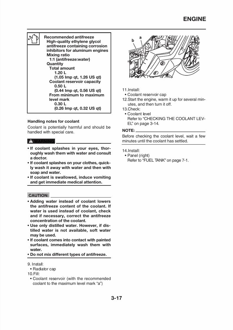
8/12/2019 Yamaha Tenere XT660Z Service Manual
http://slidepdf.com/reader/full/yamaha-tenere-xt660z-service-manual 103/398
Recommended antifreezeHigh-quality ethylene glycol
antifreeze containing corrosioninhibitors for aluminum enginesMixing ratio
1:1 (antifreeze:water)Quantity
Total amount1.20 L(1.05 Imp qt, 1.26 US qt)
Coolant reservoir capacity
0.50 L(0.44 Imp qt, 0.56 US qt)
From minimum to maximumlevel mark
0.30 L(0.26 Imp qt, 0.32 US qt)
Handling notes for coolant
Coolant is potentially harmful and should behandled with special care.
WARNING
• If coolant splashes in your eyes, thor-
oughly wash them with water and consult
a doctor.
• If coolant splashes on your clothes, quick-
ly wash it away with water and then withsoap and water.
11.Install:• Coolant reservoir cap
12.Start the engine, warm it up for several min-utes, and then turn it off.
13.Check:• Coolant level
Refer to “CHECKING THE COOLANT LEV-EL” on page 3-14.
NOTE:
Before checking the coolant level, wait a fewminutes until the coolant has settled.
14.Install:• Panel (right)
Refer to “FUEL TANK” on page 7-1.
CHASSIS
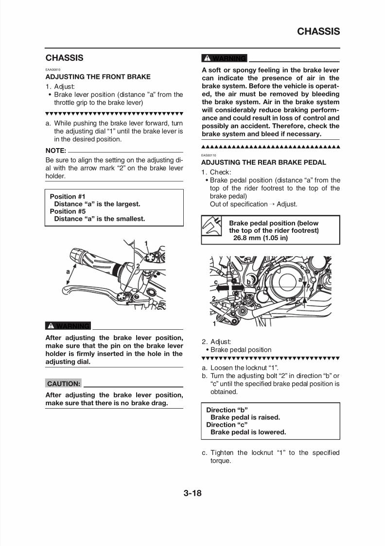
8/12/2019 Yamaha Tenere XT660Z Service Manual
http://slidepdf.com/reader/full/yamaha-tenere-xt660z-service-manual 104/398
CHASSIS
EAA00810
ADJUSTING THE FRONT BRAKE
1. Adjust:• Brake lever position (distance ”a” from the
throttle grip to the brake lever)
a. While pushing the brake lever forward, turnthe adjusting dial “1” until the brake lever isin the desired position.
NOTE:
Be sure to align the setting on the adjusting di-al with the arrow mark “2” on the brake leverholder.
Position #1Distance “a” is the largest.
Position #5Distance “a” is the smallest.
WARNING
A soft or spongy feeling in the brake lever
can indicate the presence of air in thebrake system. Before the vehicle is operat-
ed, the air must be removed by bleeding
the brake system. Air in the brake system
will considerably reduce braking perform-
ance and could result in loss of control and
possibly an accident. Therefore, check the
brake system and bleed if necessary.
Brake pedal position (belowthe top of the rider footrest)
26.8 mm (1.05 in)
EAS00110
ADJUSTING THE REAR BRAKE PEDAL
1. Check:• Brake pedal position (distance “a” from the
top of the rider footrest to the top of thebrake pedal)Out of specification → Adjust.
CHASSIS
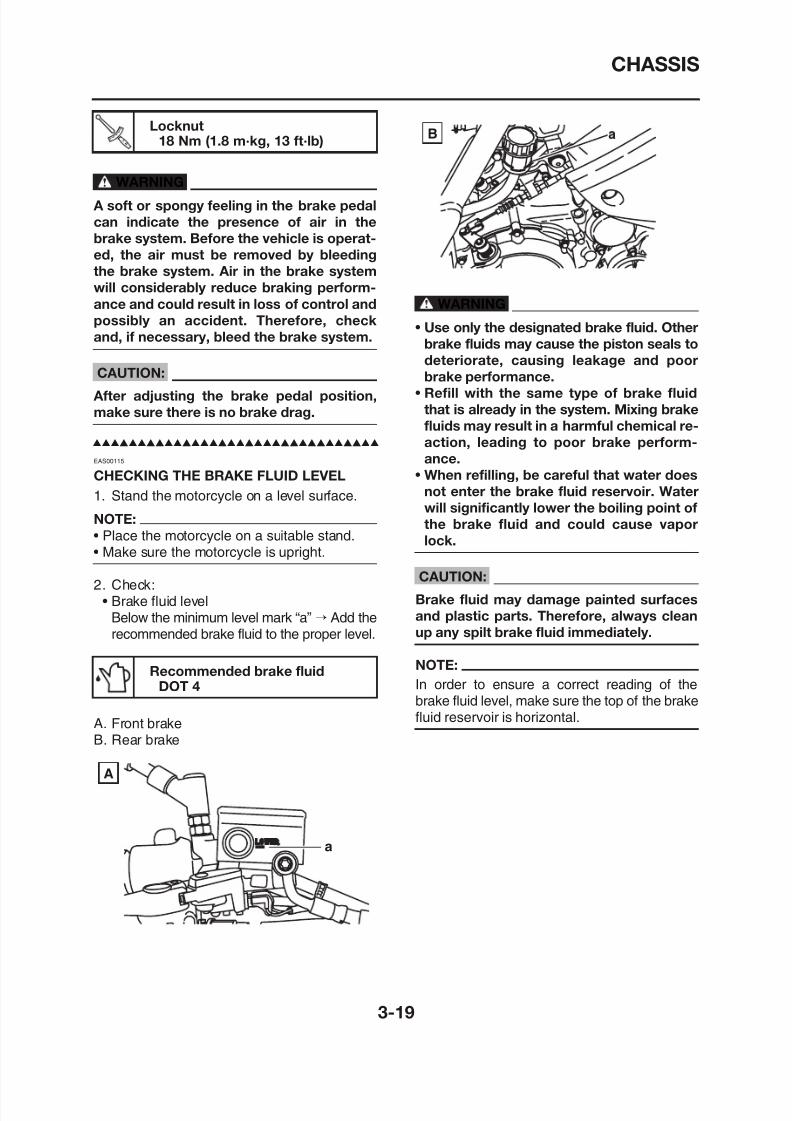
8/12/2019 Yamaha Tenere XT660Z Service Manual
http://slidepdf.com/reader/full/yamaha-tenere-xt660z-service-manual 105/398
Locknut18 Nm (1.8 m·kg, 13 ft·lb)
WARNING
A soft or spongy feeling in the brake pedal
can indicate the presence of air in the
brake system. Before the vehicle is operat-
ed, the air must be removed by bleeding
the brake system. Air in the brake system
will considerably reduce braking perform-ance and could result in loss of control and
possibly an accident. Therefore, check
and, if necessary, bleed the brake system.
CAUTION:
After adjusting the brake pedal position,
make sure there is no brake drag.
EAS00115
CHECKING THE BRAKE FLUID LEVEL
1. Stand the motorcycle on a level surface.
NOTE:
• Place the motorcycle on a suitable stand.• Make sure the motorcycle is upright.
2. Check:
WARNING
• Use only the designated brake fluid. Other
brake fluids may cause the piston seals to
deteriorate, causing leakage and poor
brake performance.
• Refill with the same type of brake fluid
that is already in the system. Mixing brake
fluids may result in a harmful chemical re-action, leading to poor brake perform-
ance.
• When refilling, be careful that water does
not enter the brake fluid reservoir. Water
will significantly lower the boiling point of
the brake fluid and could cause vapor
lock.
CAUTION:
B k fl id d i d f
B
CHASSIS
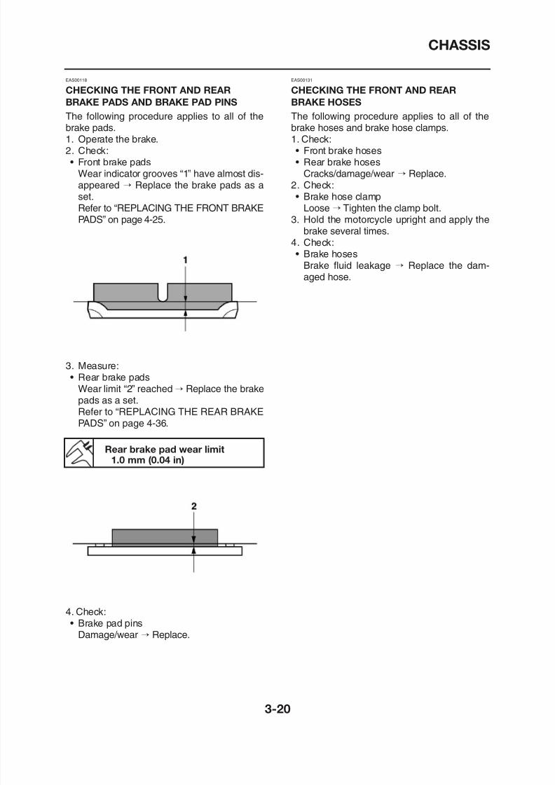
8/12/2019 Yamaha Tenere XT660Z Service Manual
http://slidepdf.com/reader/full/yamaha-tenere-xt660z-service-manual 106/398
EAS00118
CHECKING THE FRONT AND REAR
BRAKE PADS AND BRAKE PAD PINS
The following procedure applies to all of thebrake pads.1. Operate the brake.2. Check:• Front brake pads
Wear indicator grooves “1” have almost dis-appeared → Replace the brake pads as aset.
Refer to “REPLACING THE FRONT BRAKEPADS” on page 4-25.
3. Measure:• Rear brake pads
Wear limit “2” reached → Replace the brake
pads as a set.Refer to “REPLACING THE REAR BRAKE
EAS00131
CHECKING THE FRONT AND REAR
BRAKE HOSES
The following procedure applies to all of thebrake hoses and brake hose clamps.1. Check:• Front brake hoses• Rear brake hoses
Cracks/damage/wear → Replace.2. Check:• Brake hose clamp
Loose → Tighten the clamp bolt.3. Hold the motorcycle upright and apply the
brake several times.4. Check:• Brake hoses
Brake fluid leakage → Replace the dam-aged hose.
CHASSIS
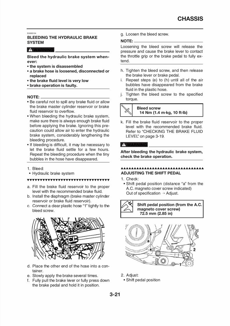
8/12/2019 Yamaha Tenere XT660Z Service Manual
http://slidepdf.com/reader/full/yamaha-tenere-xt660z-service-manual 107/398
EAS00134
BLEEDING THE HYDRAULIC BRAKE
SYSTEM
WARNING
Bleed the hydraulic brake system when-
ever:
• the system is disassembled
• a brake hose is loosened, disconnected or
replaced
• the brake fluid level is very low
• brake operation is faulty.
NOTE:
• Be careful not to spill any brake fluid or allowthe brake master cylinder reservoir or brakefluid reservoir to overflow.
• When bleeding the hydraulic brake system,make sure there is always enough brake fluid
before applying the brake. Ignoring this pre-caution could allow air to enter the hydraulicbrake system, considerably lengthening thebleeding procedure.
• If bleeding is difficult, it may be necessary tolet the brake fluid settle for a few hours.Repeat the bleeding procedure when the tinybubbles in the hose have disappeared.
1. Bleed:• Hydraulic brake system
g. Loosen the bleed screw.
NOTE:
Loosening the bleed screw will release thepressure and cause the brake lever to contactthe throttle grip or the brake pedal to fully ex-tend.
h. Tighten the bleed screw, and then releasethe brake lever or brake pedal.
i. Repeat steps (e) to (h) until all of the air
bubbles have disappeared from the brakefluid in the plastic hose.
j. Tighten the bleed screw to the specifiedtorque.
k. Fill the brake fluid reservoir to the proper
level with the recommended brake fluid.Refer to “CHECKING THE BRAKE FLUIDLEVEL” on page 3-19.
WARNING
After bleeding the hydraulic brake system,
check the brake operation.
Bleed screw14 Nm (1.4 m·kg, 10 ft·lb)
ADJUSTING THE SHIFT PEDAL
CHASSIS
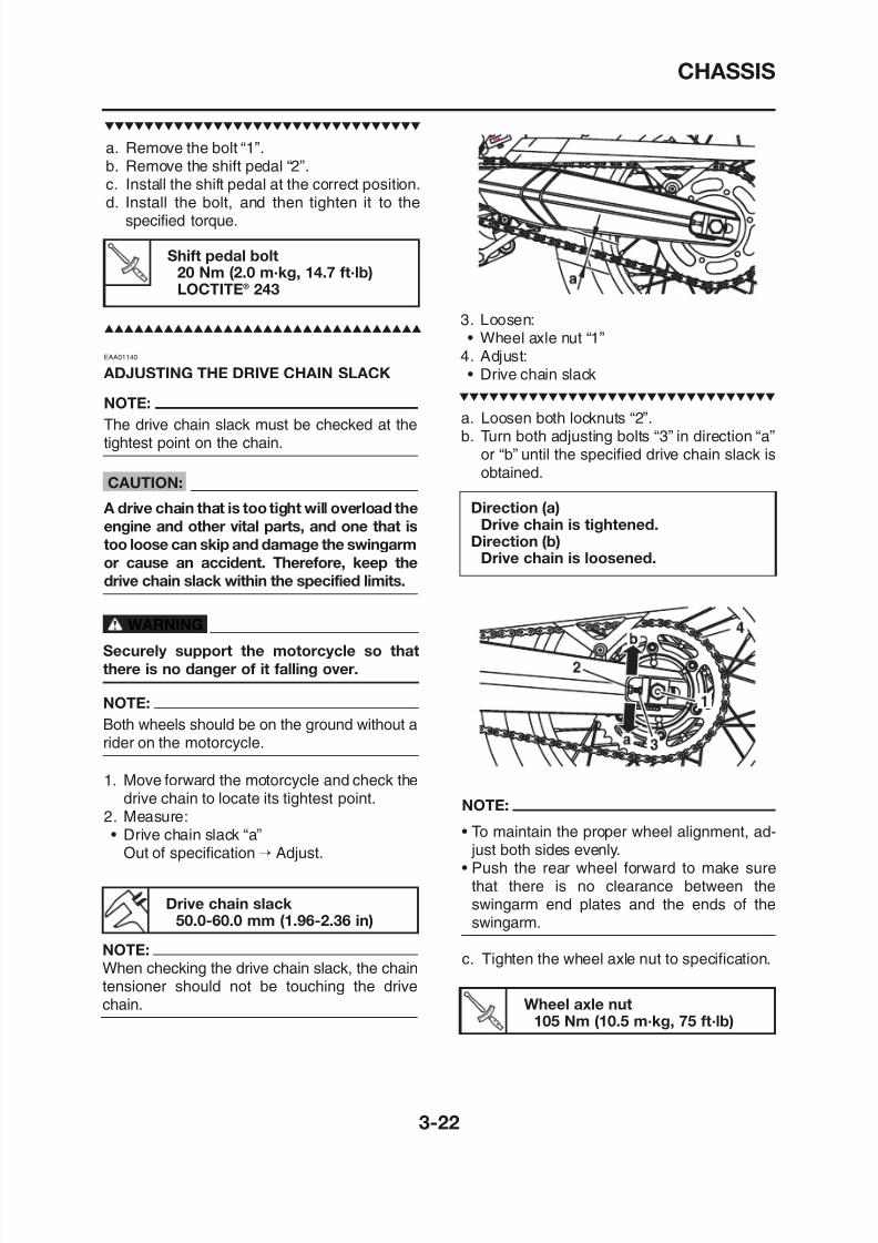
8/12/2019 Yamaha Tenere XT660Z Service Manual
http://slidepdf.com/reader/full/yamaha-tenere-xt660z-service-manual 108/398
3. Loosen:• Wheel axle nut “1”4. Adjust:• Drive chain slack
a. Loosen both locknuts “2”.b. Turn both adjusting bolts “3” in direction “a”
or “b” until the specified drive chain slack is
obtained.
Direction (a)Drive chain is tightened.
Direction (b)Drive chain is loosened.
EAA01140
ADJUSTING THE DRIVE CHAIN SLACK
NOTE:
The drive chain slack must be checked at thetightest point on the chain.
CAUTION:
A drive chain that is too tight will overload the
engine and other vital parts, and one that is
too loose can skip and damage the swingarm
or cause an accident. Therefore, keep the
drive chain slack within the specified limits.
WARNINGSecurely support the motorcycle so that
a. Remove the bolt “1”.
b. Remove the shift pedal “2”.c. Install the shift pedal at the correct position.d. Install the bolt, and then tighten it to the
specified torque.
Shift pedal bolt20 Nm (2.0 m·kg, 14.7 ft·lb)LOCTITE® 243
CHASSIS
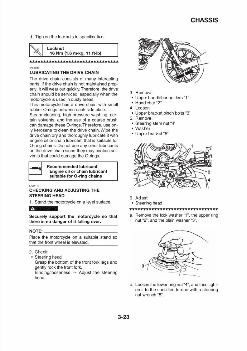
8/12/2019 Yamaha Tenere XT660Z Service Manual
http://slidepdf.com/reader/full/yamaha-tenere-xt660z-service-manual 109/398
d. Tighten the locknuts to specification.
EAS00142
LUBRICATING THE DRIVE CHAIN
The drive chain consists of many interactingparts. If the drive chain is not maintained prop-erly, it will wear out quickly. Therefore, the drivechain should be serviced, especially when themotorcycle is used in dusty areas.This motorcycle has a drive chain with smallrubber O-rings between each side plate.Steam cleaning, high-pressure washing, cer-tain solvents, and the use of a coarse brushcan damage these O-rings.Therefore, use on-ly kerosene to clean the drive chain.Wipe the
drive chain dry and thoroughly lubricate it withengine oil or chain lubricant that is suitable forO-ring chains. Do not use any other lubricantson the drive chain since they may contain sol-vents that could damage the O-rings.
EAS00146
Locknut16 Nm (1.6 m·kg, 11 ft·lb)
Recommended lubricantEngine oil or chain lubricantsuitable for O-ring chains
3. Remove:• Upper handlebar holders “1”• Handlebar “2”
4. Loosen:• Upper bracket pinch bolts “3”
5. Remove:• Steering stem nut “4”• Washer
• Upper bracket “5”
CHASSIS
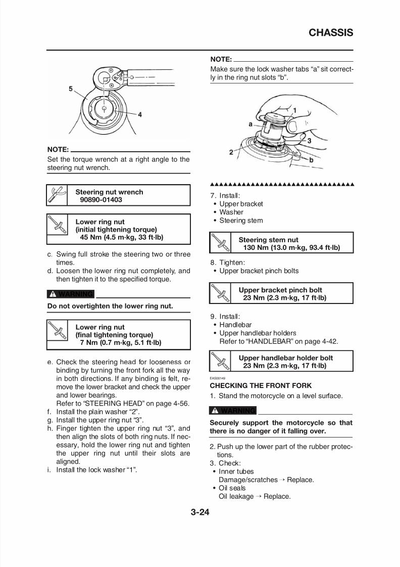
8/12/2019 Yamaha Tenere XT660Z Service Manual
http://slidepdf.com/reader/full/yamaha-tenere-xt660z-service-manual 110/398
NOTE:
Make sure the lock washer tabs “a” sit correct-
ly in the ring nut slots “b”.
7. Install:• Upper bracket• Washer
• Steering stem
8. Tighten:• Upper bracket pinch bolts
Steering stem nut130 Nm (13.0 m·kg, 93.4 ft·lb)
Upper bracket pinch bolt23 Nm (2.3 m·kg, 17 ft·lb)
NOTE:Set the torque wrench at a right angle to thesteering nut wrench.
c. Swing full stroke the steering two or threetimes.
d. Loosen the lower ring nut completely, andthen tighten it to the specified torque.
WARNING
Steering nut wrench90890-01403
Lower ring nut(initial tightening torque)
45 Nm (4.5 m·kg, 33 ft·lb)
CHASSIS
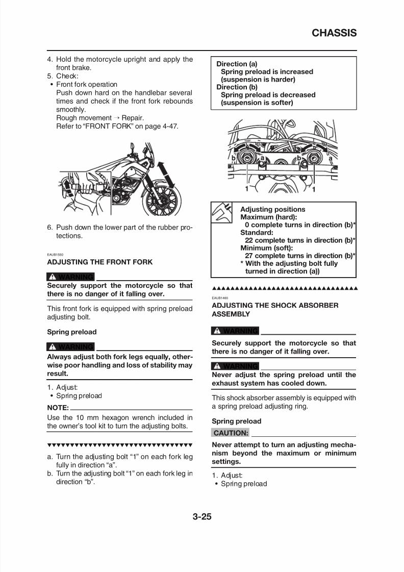
8/12/2019 Yamaha Tenere XT660Z Service Manual
http://slidepdf.com/reader/full/yamaha-tenere-xt660z-service-manual 111/398
EAUB1460
ADJUSTING THE SHOCK ABSORBER
Direction (a)Spring preload is increased
(suspension is harder)Direction (b)
Spring preload is decreased(suspension is softer)
EAUB1550
ADJUSTING THE FRONT FORK
WARNING
Securely support the motorcycle so that
there is no danger of it falling over.
4. Hold the motorcycle upright and apply thefront brake.
5. Check:• Front fork operation
Push down hard on the handlebar severaltimes and check if the front fork reboundssmoothly.Rough movement → Repair.Refer to “FRONT FORK” on page 4-47.
6. Push down the lower part of the rubber pro-tections.
Adjusting positionsMaximum (hard):
0 complete turns in direction (b)*Standard:
22 complete turns in direction (b)*Minimum (soft):
27 complete turns in direction (b)** With the adjusting bolt fully
turned in direction (a))
CHASSIS
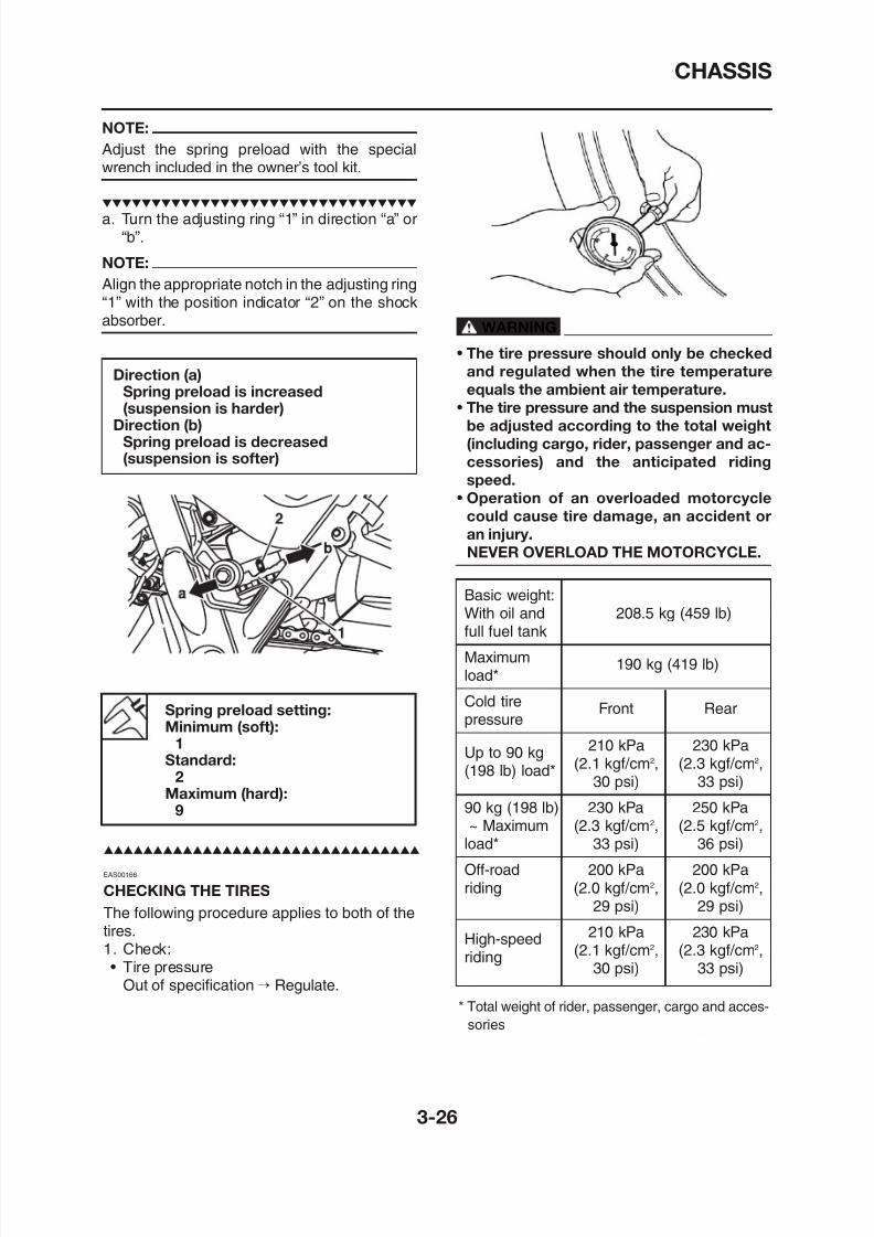
8/12/2019 Yamaha Tenere XT660Z Service Manual
http://slidepdf.com/reader/full/yamaha-tenere-xt660z-service-manual 112/398
Basic weight:With oil and 208.5 kg (459 lb)
full fuel tank
Maximum
NOTE:
Adjust the spring preload with the special
wrench included in the owner’s tool kit.
a. Turn the adjusting ring “1” in direction “a” or“b”.
NOTE:
Align the appropriate notch in the adjusting ring“1” with the position indicator “2” on the shock
absorber.
Direction (a)Spring preload is increased(suspension is harder)
Direction (b)Spring preload is decreased(suspension is softer)
WARNING
• The tire pressure should only be checked
and regulated when the tire temperature
equals the ambient air temperature.
• The tire pressure and the suspension must
be adjusted according to the total weight
(including cargo, rider, passenger and ac-
cessories) and the anticipated riding
speed.• Operation of an overloaded motorcycle
could cause tire damage, an accident or
an injury.
NEVER OVERLOAD THE MOTORCYCLE.
CHASSIS
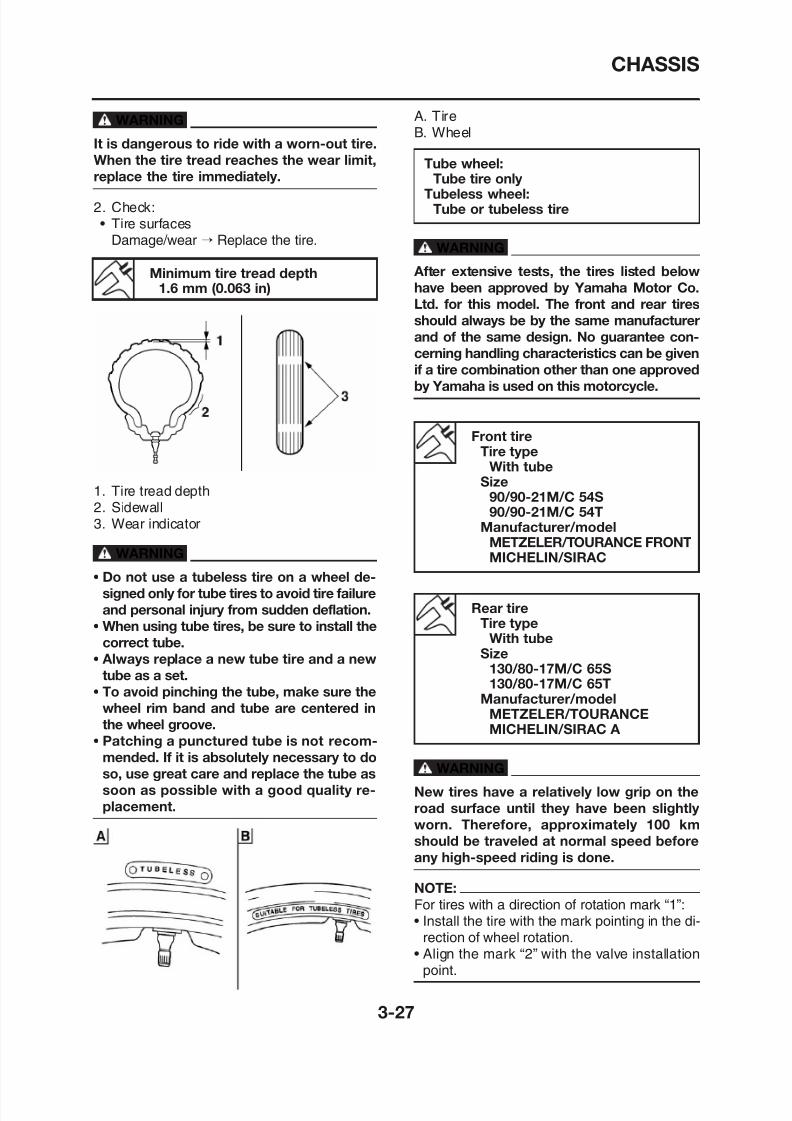
8/12/2019 Yamaha Tenere XT660Z Service Manual
http://slidepdf.com/reader/full/yamaha-tenere-xt660z-service-manual 113/398
WARNING
It is dangerous to ride with a worn-out tire.
When the tire tread reaches the wear limit,replace the tire immediately.
2. Check:• Tire surfaces
Damage/wear → Replace the tire.
1. Tire tread depth2. Sidewall3. Wear indicator
WARNING
• Do not use a tubeless tire on a wheel de-
signed only for tube tires to avoid tire failure
A. TireB. Wheel
WARNING
After extensive tests, the tires listed below
have been approved by Yamaha Motor Co.
Ltd. for this model. The front and rear tires
should always be by the same manufacturer
and of the same design. No guarantee con-
cerning handling characteristics can be given
if a tire combination other than one approved
by Yamaha is used on this motorcycle.
Tube wheel:Tube tire only
Tubeless wheel:Tube or tubeless tire
Minimum tire tread depth
1.6 mm (0.063 in)
Front tireTire type
With tubeSize
90/90-21M/C 54S90/90-21M/C 54T
Manufacturer/modelMETZELER/TOURANCE FRONTMICHELIN/SIRAC
CHASSIS
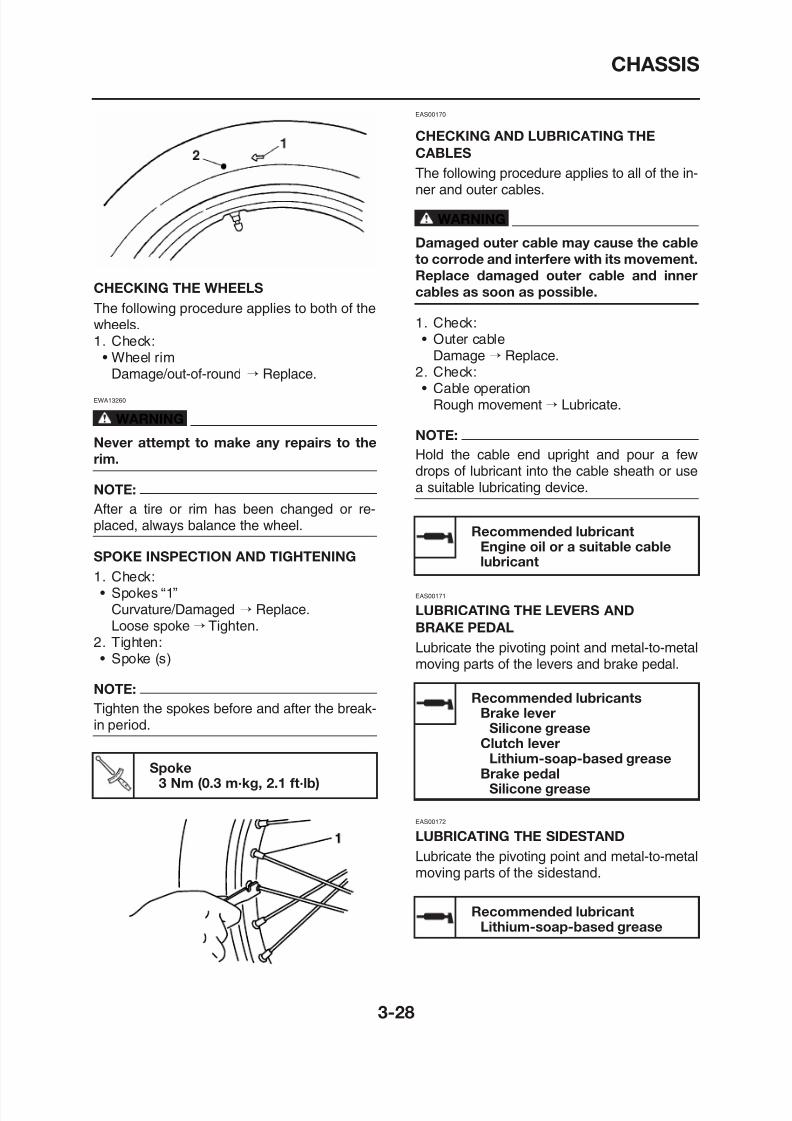
8/12/2019 Yamaha Tenere XT660Z Service Manual
http://slidepdf.com/reader/full/yamaha-tenere-xt660z-service-manual 114/398
CHECKING THE WHEELSThe following procedure applies to both of thewheels.1. Check:
• Wheel rimDamage/out-of-round → Replace.
EWA13260
WARNING
Never attempt to make any repairs to the
rim.
NOTE:
After a tire or rim has been changed or re-placed, always balance the wheel.
SPOKE INSPECTION AND TIGHTENING
1. Check:• Spokes “1”
EAS00170
CHECKING AND LUBRICATING THE
CABLESThe following procedure applies to all of the in-ner and outer cables.
WARNING
Damaged outer cable may cause the cable
to corrode and interfere with its movement.
Replace damaged outer cable and inner
cables as soon as possible.
1. Check:• Outer cable
Damage → Replace.2. Check:• Cable operation
Rough movement → Lubricate.
NOTE:Hold the cable end upright and pour a fewdrops of lubricant into the cable sheath or usea suitable lubricating device.
EAS00171
Recommended lubricantEngine oil or a suitable cablelubricant
CHASSIS
8/12/2019 Yamaha Tenere XT660Z Service Manual
http://slidepdf.com/reader/full/yamaha-tenere-xt660z-service-manual 115/398
Recommended lubricantLithium-soap-based grease
LUBRICATING THE REAR SUSPENSION
The pivoting points of the rear suspension mustbe lubricated at the intervals specified in the pe-riodic maintenance and lubrication chart.
LUBRICATING THE SWINGARM PIVOTS
The swingarm pivots must be lubricated at theintervals specified in the periodic maintenance
and lubrication chart.
Recommended lubricantLithium-soap-based grease
ELECTRICAL SYSTEM
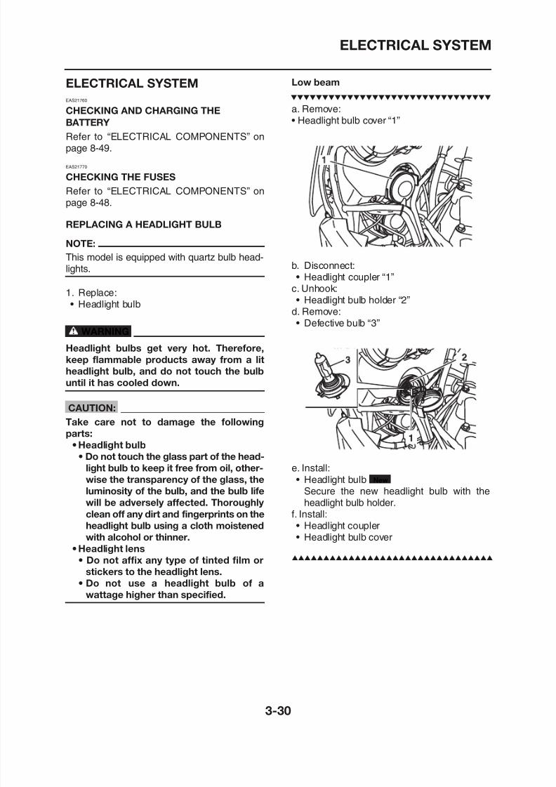
8/12/2019 Yamaha Tenere XT660Z Service Manual
http://slidepdf.com/reader/full/yamaha-tenere-xt660z-service-manual 116/398
ELECTRICAL SYSTEM
EAS21760
CHECKING AND CHARGING THEBATTERY
Refer to “ELECTRICAL COMPONENTS” onpage 8-49.
EAS21770
CHECKING THE FUSES
Refer to “ELECTRICAL COMPONENTS” on
page 8-48.
REPLACING A HEADLIGHT BULB
NOTE:
This model is equipped with quartz bulb head-lights.
1. Replace:
• Headlight bulb
WARNING
Headlight bulbs get very hot. Therefore,
keep flammable products away from a lit
headlight bulb, and do not touch the bulb
until it has cooled down.
CAUTION:
Low beam
a. Remove:• Headlight bulb cover “1”
b. Disconnect:• Headlight coupler “1”
c. Unhook:
• Headlight bulb holder “2”d. Remove:• Defective bulb “3”
ELECTRICAL SYSTEM
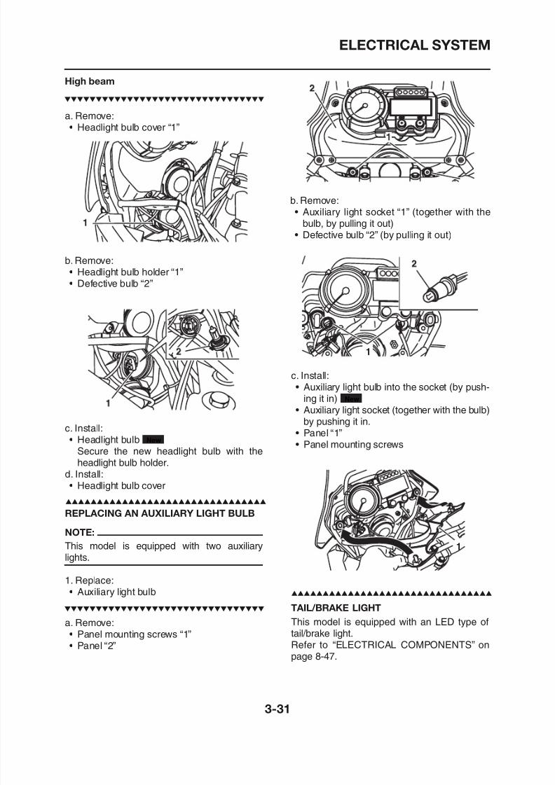
8/12/2019 Yamaha Tenere XT660Z Service Manual
http://slidepdf.com/reader/full/yamaha-tenere-xt660z-service-manual 117/398
a. Remove:• Headlight bulb cover “1”
b. Remove:• Headlight bulb holder “1”• Defective bulb “2”
c. Install:• Auxiliary light bulb into the socket (by push-
ing it in)• Auxiliary light socket (together with the bulb)
New
b. Remove:• Auxiliary light socket “1” (together with the
bulb, by pulling it out)• Defective bulb “2” (by pulling it out)
High beam
ELECTRICAL SYSTEM
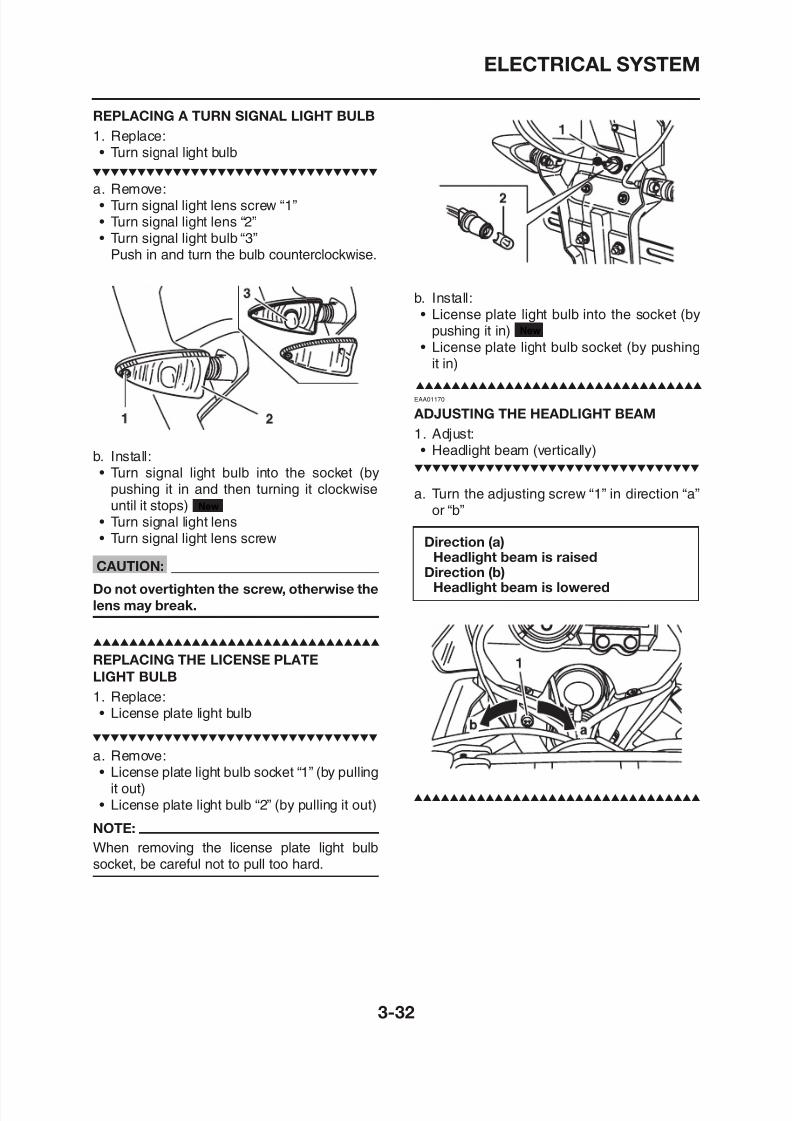
8/12/2019 Yamaha Tenere XT660Z Service Manual
http://slidepdf.com/reader/full/yamaha-tenere-xt660z-service-manual 118/398
REPLACING A TURN SIGNAL LIGHT BULB
1. Replace:
• Turn signal light bulb
a. Remove:• Turn signal light lens screw “1”• Turn signal light lens “2”• Turn signal light bulb “3”
Push in and turn the bulb counterclockwise.
b. Install:• Turn signal light bulb into the socket (by
pushing it in and then turning it clockwiseuntil it stops)
• Turn signal light lens• Turn signal light lens screw
CAUTION:Do not overtighten the screw, otherwise the
New
b. Install:• License plate light bulb into the socket (by
pushing it in)• License plate light bulb socket (by pushing
it in)
EAA01170
ADJUSTING THE HEADLIGHT BEAM
1. Adjust:• Headlight beam (vertically)
a. Turn the adjusting screw “1” in direction “a”or “b”
New
Direction (a)Headlight beam is raised
Direction (b)Headlight beam is lowered
8/12/2019 Yamaha Tenere XT660Z Service Manual
http://slidepdf.com/reader/full/yamaha-tenere-xt660z-service-manual 119/398
CHASSIS
GENERAL CHASSIS ...................................................................................... 4-1REMOVING THE SEAT AND THE ASSIST GRIPS................................. 4-1REMOVING THE COWLING ................................................................... 4-2REMOVING THE HEADLIGHT ............................................................... 4-3REMOVING THE REAR FENDER COVER, LICENSE BRACKETAND TAIL/BRAKE LIGHT ASSEMBLY .................................................... 4-4REMOVING THE AIR FILTER CASE AND CRANKCASEBREATHER CHAMBER .......................................................................... 4-5INSTALLING THE AIR FILTER CASE JOINT CLAMP............................. 4-6
FRONT WHEEL ............................................................................................. 4-7REMOVING THE FRONT WHEEL........................................................... 4-9DISASSEMBLING THE FRONT WHEEL................................................. 4-9CHECKING THE FRONT WHEEL ........................................................... 4-9ASSEMBLING THE FRONT WHEEL.......................................................4-10ADJUSTING THE FRONT WHEEL STATIC BALANCE...........................4-11
CHECKING THE FRONT BRAKE DISCS................................................4-12INSTALLING THE FRONT WHEEL (FRONT BRAKE DISCS) ...............4-12
REAR WHEEL ................................................................................................4-14REMOVING THE REAR WHEEL .............................................................4-17DISASSEMBLING THE REAR WHEEL ...................................................4-17CHECKING THE REAR WHEEL..............................................................4-17CHECKING THE REAR WHEEL DRIVE HUB.........................................4-18
CHECKING AND REPLACING THE REAR WHEEL SPROCKET ..........4-18ASSEMBLING THE REAR WHEEL .........................................................4-18
4
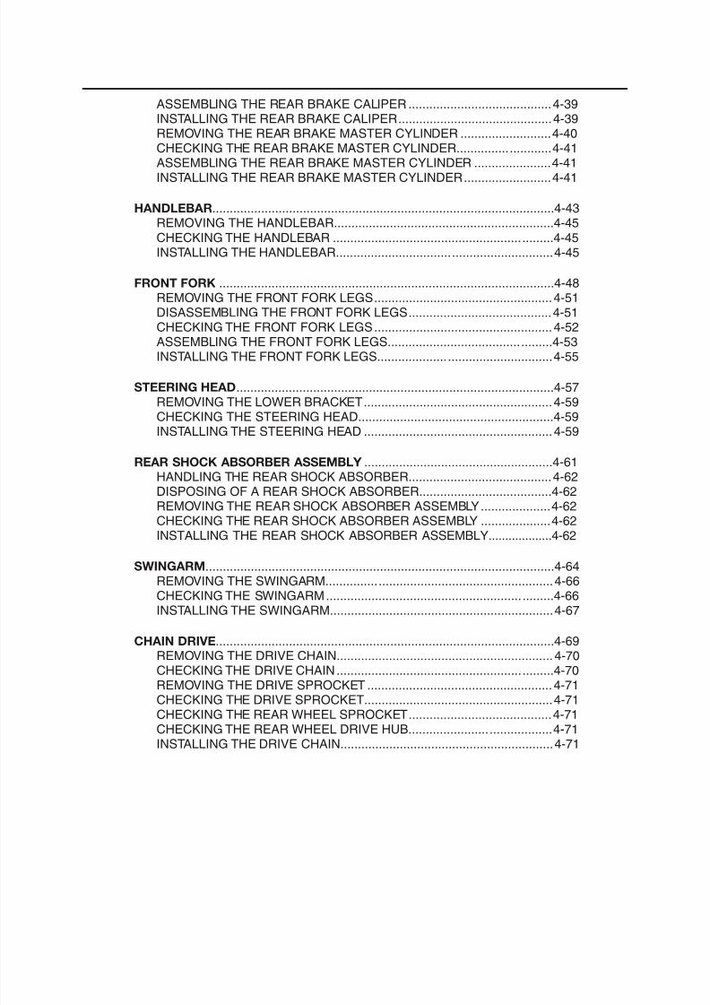
8/12/2019 Yamaha Tenere XT660Z Service Manual
http://slidepdf.com/reader/full/yamaha-tenere-xt660z-service-manual 120/398
ASSEMBLING THE REAR BRAKE CALIPER .........................................4-39INSTALLING THE REAR BRAKE CALIPER............................................4-39REMOVING THE REAR BRAKE MASTER CYLINDER ..........................4-40CHECKING THE REAR BRAKE MASTER CYLINDER...........................4-41ASSEMBLING THE REAR BRAKE MASTER CYLINDER ......................4-41INSTALLING THE REAR BRAKE MASTER CYLINDER.........................4-41
HANDLEBAR..................................................................................................4-43REMOVING THE HANDLEBAR...............................................................4-45CHECKING THE HANDLEBAR ...............................................................4-45INSTALLING THE HANDLEBAR..............................................................4-45
FRONT FORK ................................................................................................4-48REMOVING THE FRONT FORK LEGS...................................................4-51DISASSEMBLING THE FRONT FORK LEGS.........................................4-51CHECKING THE FRONT FORK LEGS...................................................4-52ASSEMBLING THE FRONT FORK LEGS...............................................4-53INSTALLING THE FRONT FORK LEGS..................................................4-55
STEERING HEAD...........................................................................................4-57REMOVING THE LOWER BRACKET......................................................4-59CHECKING THE STEERING HEAD........................................................4-59INSTALLING THE STEERING HEAD ......................................................4-59
REAR SHOCK ABSORBER ASSEMBLY ......................................................4-61HANDLING THE REAR SHOCK ABSORBER.........................................4-62DISPOSING OF A REAR SHOCK ABSORBER......................................4-62REMOVING THE REAR SHOCK ABSORBER ASSEMBLY....................4-62CHECKING THE REAR SHOCK ABSORBER ASSEMBLY ....................4-62INSTALLING THE REAR SHOCK ABSORBER ASSEMBLY 4 62
GENERAL CHASSIS
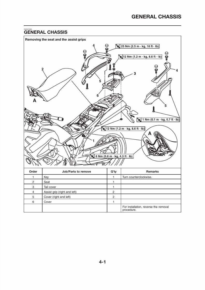
8/12/2019 Yamaha Tenere XT660Z Service Manual
http://slidepdf.com/reader/full/yamaha-tenere-xt660z-service-manual 121/398
EAS21830
GENERAL CHASSIS
Removing the seat and the assist grips
GENERAL CHASSIS
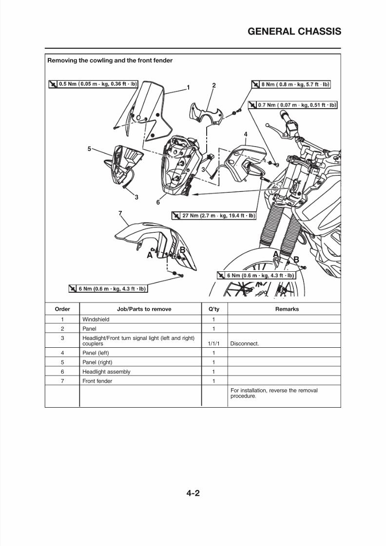
8/12/2019 Yamaha Tenere XT660Z Service Manual
http://slidepdf.com/reader/full/yamaha-tenere-xt660z-service-manual 122/398
Removing the cowling and the front fender
GENERAL CHASSIS
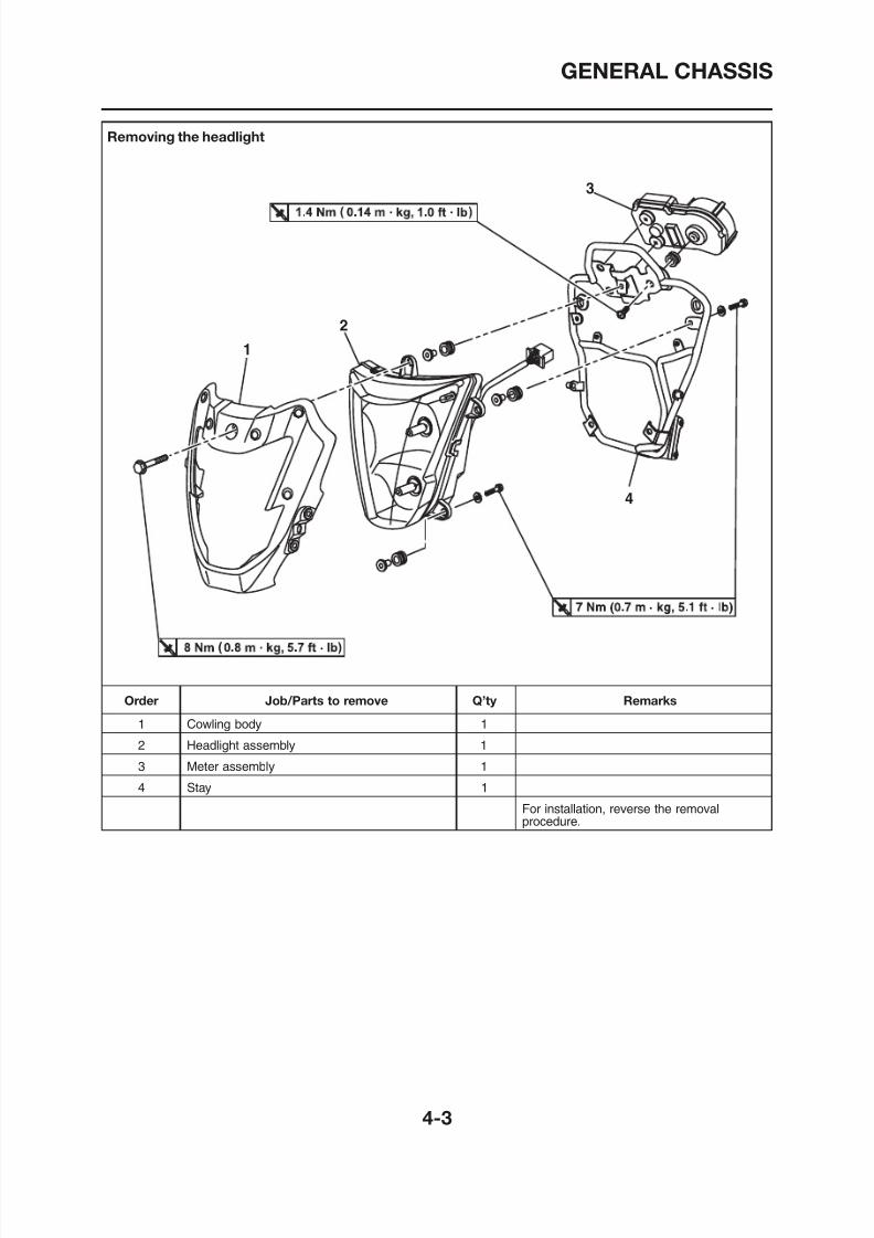
8/12/2019 Yamaha Tenere XT660Z Service Manual
http://slidepdf.com/reader/full/yamaha-tenere-xt660z-service-manual 123/398
Removing the headlight
GENERAL CHASSIS
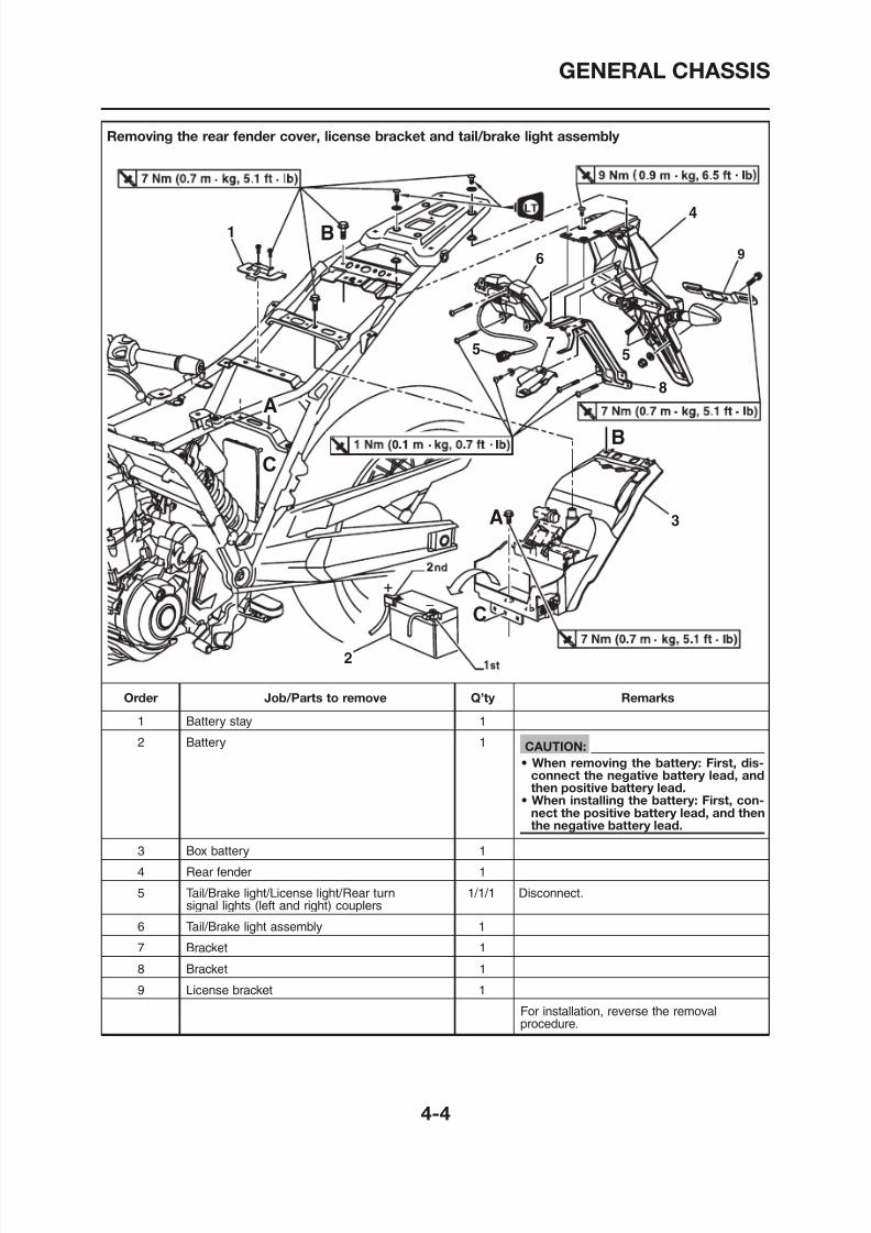
8/12/2019 Yamaha Tenere XT660Z Service Manual
http://slidepdf.com/reader/full/yamaha-tenere-xt660z-service-manual 124/398
Removing the rear fender cover, license bracket and tail/brake light assembly
GENERAL CHASSIS
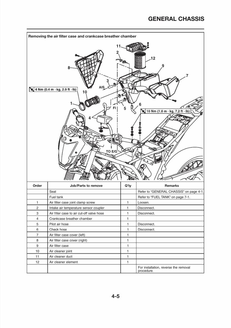
8/12/2019 Yamaha Tenere XT660Z Service Manual
http://slidepdf.com/reader/full/yamaha-tenere-xt660z-service-manual 125/398
Removing the air filter case and crankcase breather chamber
GENERAL CHASSIS
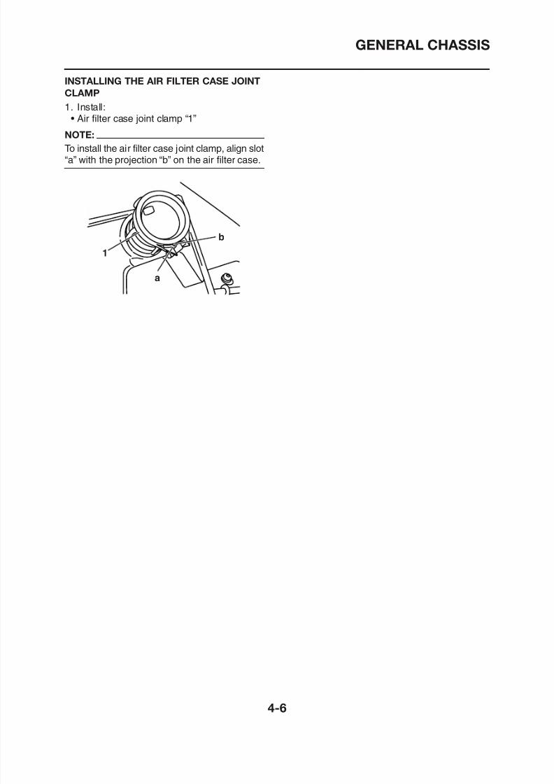
8/12/2019 Yamaha Tenere XT660Z Service Manual
http://slidepdf.com/reader/full/yamaha-tenere-xt660z-service-manual 126/398
INSTALLING THE AIR FILTER CASE JOINT
CLAMP
1. Install:• Air filter case joint clamp “1”
NOTE:
To install the air filter case joint clamp, align slot“a” with the projection “b” on the air filter case.
1
a
b
FRONT WHEEL
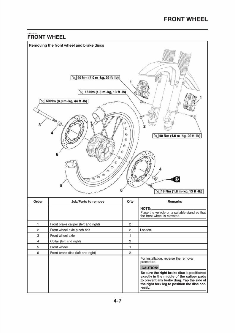
8/12/2019 Yamaha Tenere XT660Z Service Manual
http://slidepdf.com/reader/full/yamaha-tenere-xt660z-service-manual 127/398
Removing the front wheel and brake discs
EAS21870
FRONT WHEEL
FRONT WHEEL
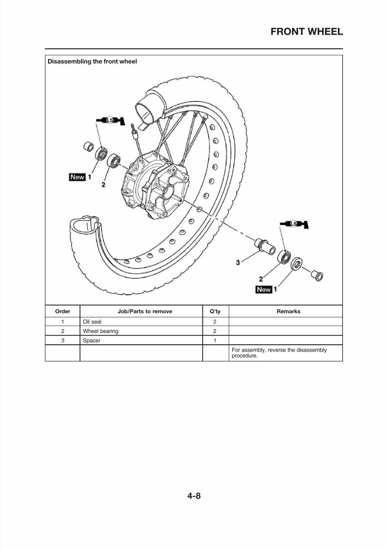
8/12/2019 Yamaha Tenere XT660Z Service Manual
http://slidepdf.com/reader/full/yamaha-tenere-xt660z-service-manual 128/398
Disassembling the front wheel
FRONT WHEEL
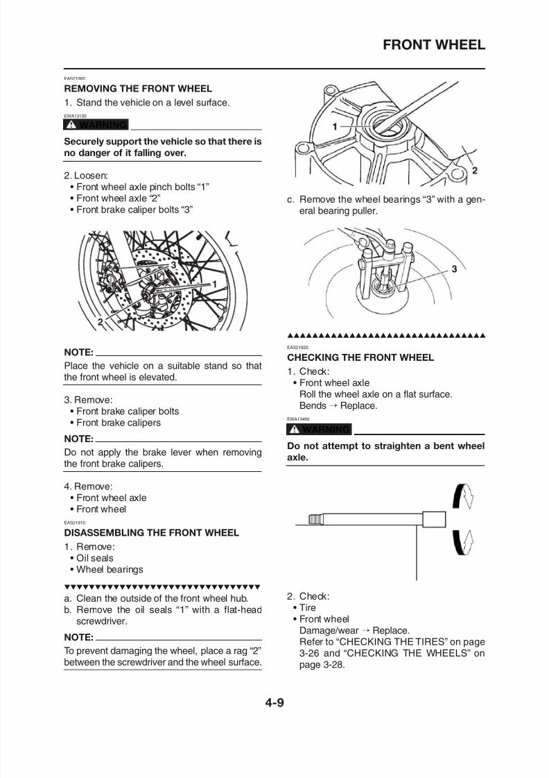
8/12/2019 Yamaha Tenere XT660Z Service Manual
http://slidepdf.com/reader/full/yamaha-tenere-xt660z-service-manual 129/398
EAS21900
REMOVING THE FRONT WHEEL
1. Stand the vehicle on a level surface.
EWA13120
WARNING
Securely support the vehicle so that there is
no danger of it falling over.
2. Loosen:• Front wheel axle pinch bolts “1”• Front wheel axle “2”
• Front brake caliper bolts “3”
NOTE:
Place the vehicle on a suitable stand so thatthe front wheel is elevated.
3. Remove:• Front brake caliper bolts
c. Remove the wheel bearings “3” with a gen-eral bearing puller.
EAS21920
CHECKING THE FRONT WHEEL
1. Check:• Front wheel axle
Roll the wheel axle on a flat surface.Bends → Replace.
FRONT WHEEL
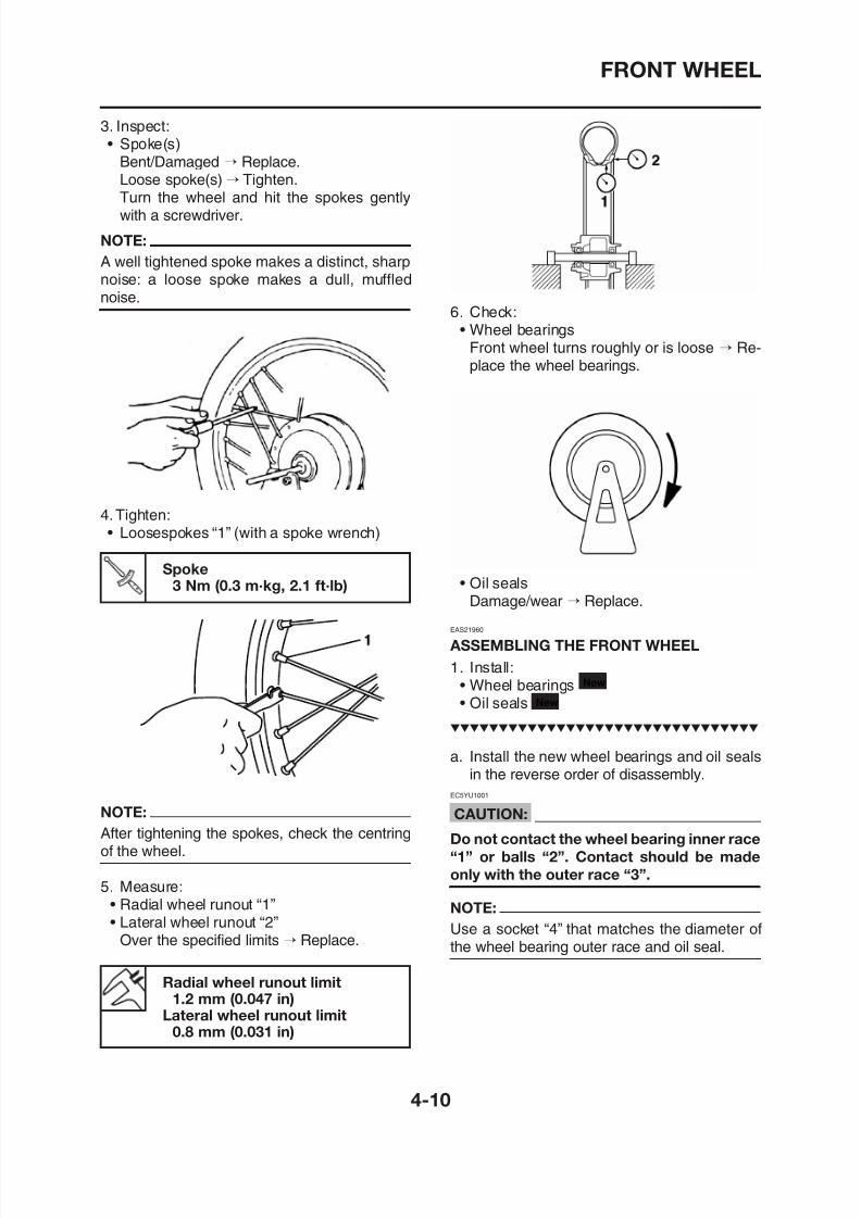
8/12/2019 Yamaha Tenere XT660Z Service Manual
http://slidepdf.com/reader/full/yamaha-tenere-xt660z-service-manual 130/398
3. Inspect:• Spoke(s)
Bent/Damaged → Replace.Loose spoke(s) → Tighten.Turn the wheel and hit the spokes gentlywith a screwdriver.
NOTE:
A well tightened spoke makes a distinct, sharpnoise: a loose spoke makes a dull, mufflednoise.
4.Tighten:• Loosespokes “1” (with a spoke wrench)
6. Check:• Wheel bearings
Front wheel turns roughly or is loose → Re-place the wheel bearings.
• Oil sealsDamage/wear → Replace.
EAS21960
ASSEMBLING THE FRONT WHEEL
Spoke3 Nm (0.3 m·kg, 2.1 ft·lb)
FRONT WHEEL
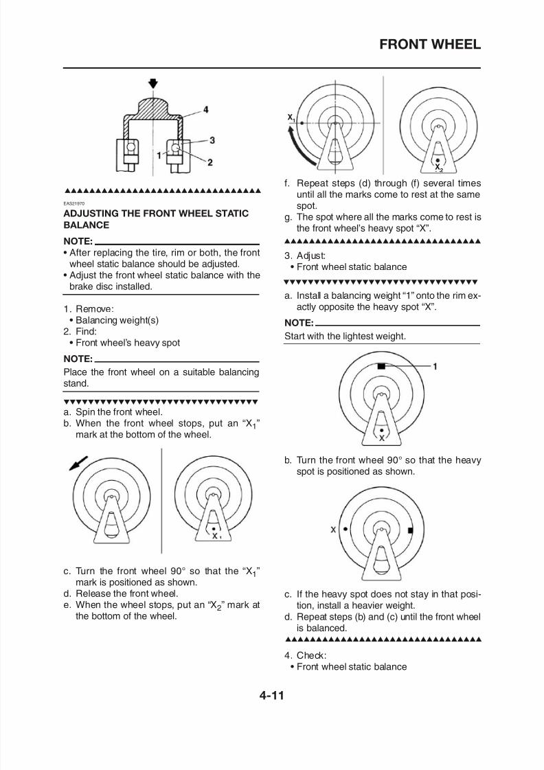
8/12/2019 Yamaha Tenere XT660Z Service Manual
http://slidepdf.com/reader/full/yamaha-tenere-xt660z-service-manual 131/398
EAS21970
ADJUSTING THE FRONT WHEEL STATIC
BALANCE
NOTE:
• After replacing the tire, rim or both, the frontwheel static balance should be adjusted.
• Adjust the front wheel static balance with thebrake disc installed.
1. Remove:• Balancing weight(s)
2. Find:• Front wheel’s heavy spot
NOTE:
Place the front wheel on a suitable balancingstand.
S i h f h l
f. Repeat steps (d) through (f) several timesuntil all the marks come to rest at the same
spot.g. The spot where all the marks come to rest is
the front wheel’s heavy spot “X”.
3. Adjust:• Front wheel static balance
a. Install a balancing weight “1” onto the rim ex-actly opposite the heavy spot “X”.
NOTE:
Start with the lightest weight.
X1
X2
FRONT WHEEL
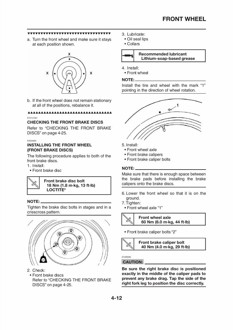
8/12/2019 Yamaha Tenere XT660Z Service Manual
http://slidepdf.com/reader/full/yamaha-tenere-xt660z-service-manual 132/398
a. Turn the front wheel and make sure it staysat each position shown.
b. If the front wheel does not remain stationaryat all of the positions, rebalance it.
ET5YU1001
CHECKING THE FRONT BRAKE DISCS
Refer to “CHECKING THE FRONT BRAKEDISCS” on page 4-25.
EAS22000
INSTALLING THE FRONT WHEEL
(FRONT BRAKE DISCS)
The following procedure applies to both of thefront brake discs.1. Install:
• Front brake disc
Recommended lubricantLithium-soap-based grease
3. Lubricate:• Oil seal lips• Collars
4. Install:• Front wheel
NOTE:
Install the tire and wheel with the mark “1”pointing in the direction of wheel rotation.
5. Install:• Front wheel axle• Front brake calipers• Front brake caliper bolts
NOTE:Make sure that there is enough space between
FRONT WHEEL
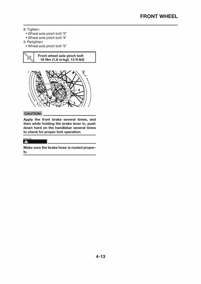
8/12/2019 Yamaha Tenere XT660Z Service Manual
http://slidepdf.com/reader/full/yamaha-tenere-xt660z-service-manual 133/398
8.Tighten:• Wheel axle pinch bolt “3”• Wheel axle pinch bolt “4”
9. Retighten:• Wheel axle pinch bolt “3”
CAUTION:
Apply the front brake several times, and
then while holding the brake lever in, push
down hard on the handlebar several times
to check for proper fork operation.
EWA13500
WARNING
Make sure the brake hose is routed proper-
l
Front wheel axle pinch bolt18 Nm (1.8 m·kgf, 13 ft·lbf)
REAR WHEEL
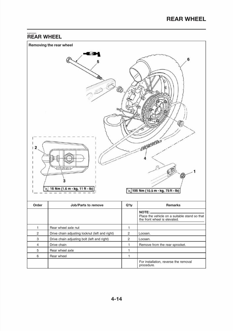
8/12/2019 Yamaha Tenere XT660Z Service Manual
http://slidepdf.com/reader/full/yamaha-tenere-xt660z-service-manual 134/398
Removing the rear wheel
EAS22020
REAR WHEEL
REAR WHEEL
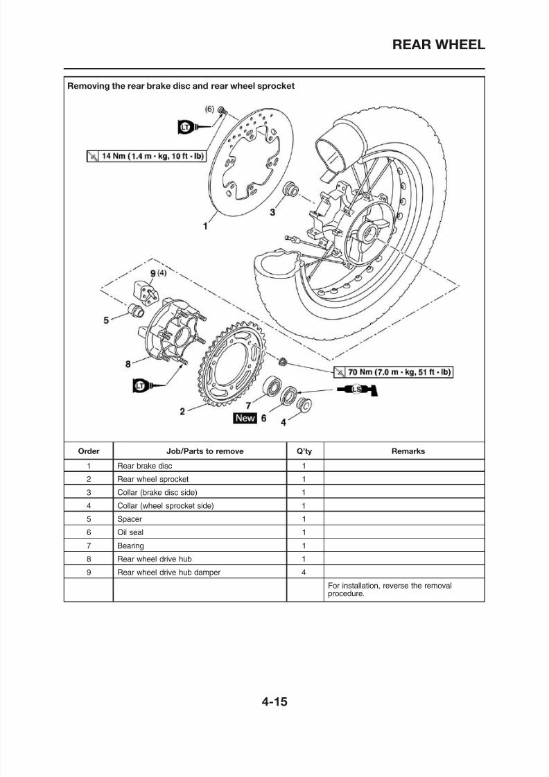
8/12/2019 Yamaha Tenere XT660Z Service Manual
http://slidepdf.com/reader/full/yamaha-tenere-xt660z-service-manual 135/398
Removing the rear brake disc and rear wheel sprocket
REAR WHEEL
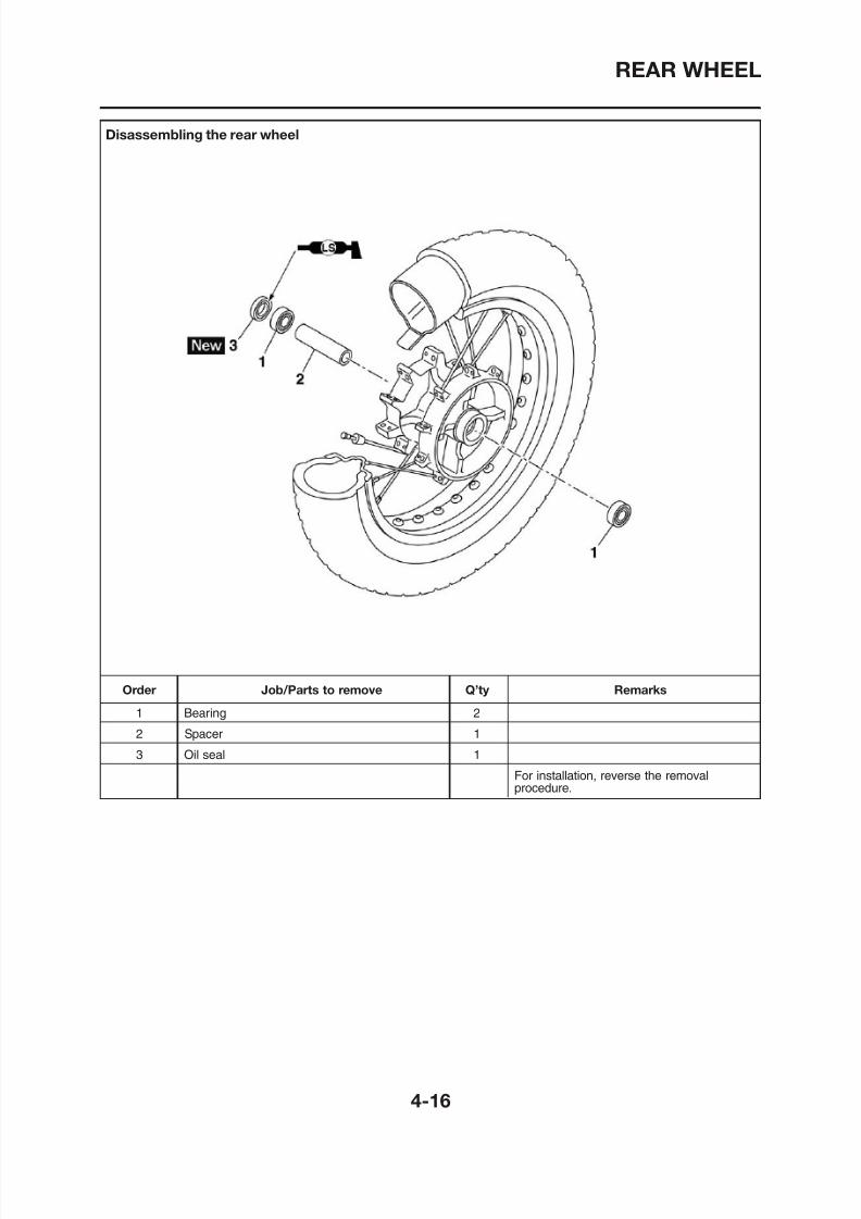
8/12/2019 Yamaha Tenere XT660Z Service Manual
http://slidepdf.com/reader/full/yamaha-tenere-xt660z-service-manual 136/398
Disassembling the rear wheel
REAR WHEEL
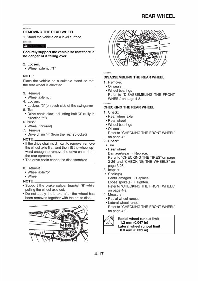
8/12/2019 Yamaha Tenere XT660Z Service Manual
http://slidepdf.com/reader/full/yamaha-tenere-xt660z-service-manual 137/398
EAS22040
REMOVING THE REAR WHEEL
1. Stand the vehicle on a level surface.
EWA13120
WARNING
Securely support the vehicle so that there is
no danger of it falling over.
2. Loosen:• Wheel axle nut “1”
NOTE:
Place the vehicle on a suitable stand so thatthe rear wheel is elevated.
3. Remove:• Wheel axle nut
4. Loosen:• Locknut “2” (on each side of the swingarm)
5. Turn:• Drive chain slack adjusting bolt “3” (fully in
direction “a”)6. Push:• Wheel (forward)
7. Remove:• Drive chain “4” (from the rear sprocket)
NOTE:
• If the drive chain is difficult to remove, removethe wheel axle first, and then lift the wheel up-
EAS22080
DISASSEMBLING THE REAR WHEEL
1. Remove:• Oil seals• Wheel bearings
Refer to “DISASSEMBLING THE FRONTWHEEL” on page 4-8.
EAS22090
CHECKING THE REAR WHEEL
1. Check:• Rear wheel axle• Rear wheel• Wheel bearings• Oil seals
Refer to “CHECKING THE FRONT WHEEL”on page 4-9.
2. Check:
• Tire• Rear wheel
REAR WHEEL
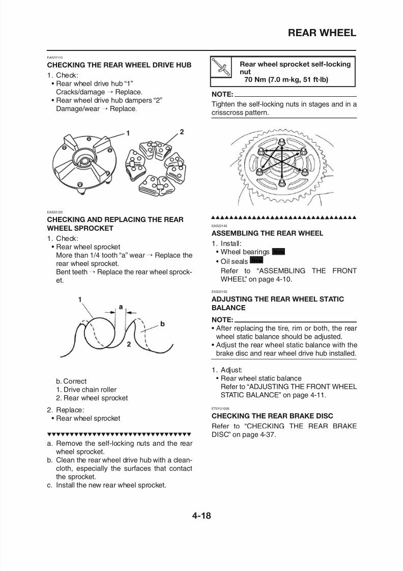
8/12/2019 Yamaha Tenere XT660Z Service Manual
http://slidepdf.com/reader/full/yamaha-tenere-xt660z-service-manual 138/398
NOTE:
Tighten the self-locking nuts in stages and in acrisscross pattern.
EAS22140
ASSEMBLING THE REAR WHEEL
1. Install:• Wheel bearings
• Oil seals
Refer to “ASSEMBLING THE FRONTWHEEL” on page 4-10.
EAS22150
ADJUSTING THE REAR WHEEL STATIC
New
New
EAS22110
CHECKING THE REAR WHEEL DRIVE HUB
1. Check:
• Rear wheel drive hub “1”Cracks/damage → Replace.
• Rear wheel drive hub dampers “2”Damage/wear → Replace.
EAS22120
CHECKING AND REPLACING THE REARWHEEL SPROCKET
1. Check:• Rear wheel sprocket
More than 1/4 tooth “a” wear→ Replace therear wheel sprocket.Bent teeth → Replace the rear wheel sprock-et.
1 2
Rear wheel sprocket self-lockingnut
70 Nm (7.0 m·kg, 51 ft·lb)
REAR WHEEL
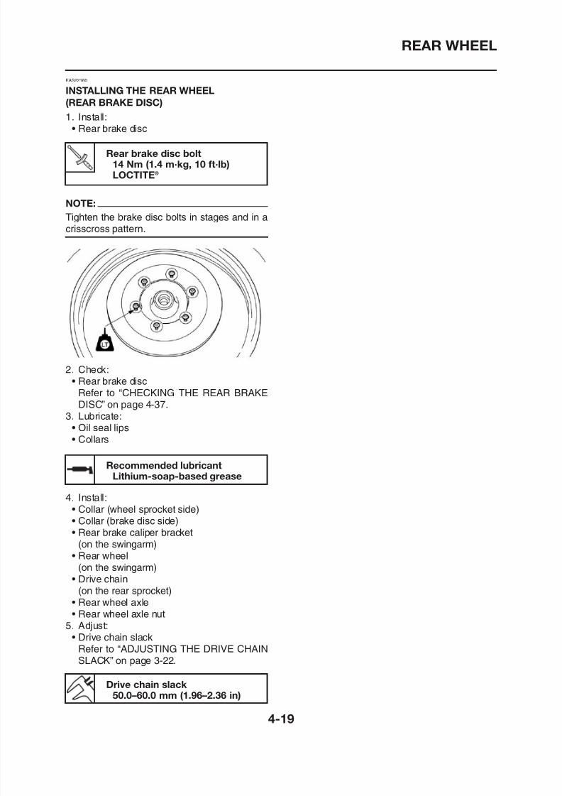
8/12/2019 Yamaha Tenere XT660Z Service Manual
http://slidepdf.com/reader/full/yamaha-tenere-xt660z-service-manual 139/398
Rear brake disc bolt14 Nm (1.4 m·kg, 10 ft·lb)LOCTITE®
EAS22160
INSTALLING THE REAR WHEEL
(REAR BRAKE DISC)
1. Install:• Rear brake disc
NOTE:
Tighten the brake disc bolts in stages and in acrisscross pattern.
2. Check:• Rear brake disc
Refer to “CHECKING THE REAR BRAKE
DISC” on page 4-37.3. Lubricate:
FRONT BRAKE
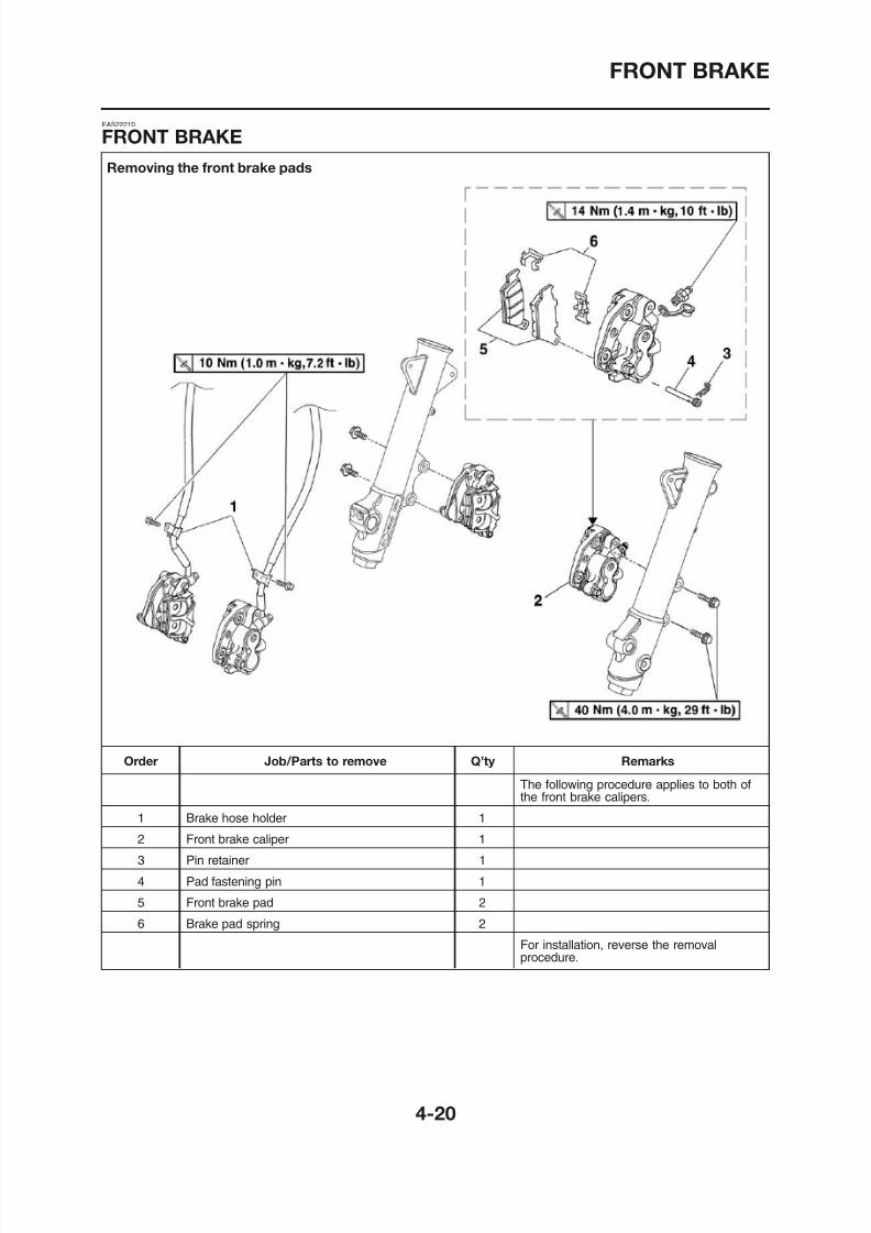
8/12/2019 Yamaha Tenere XT660Z Service Manual
http://slidepdf.com/reader/full/yamaha-tenere-xt660z-service-manual 140/398
Removing the front brake pads
EAS22210
FRONT BRAKE
FRONT BRAKE
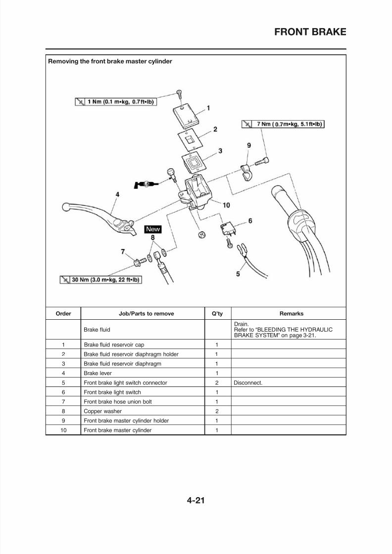
8/12/2019 Yamaha Tenere XT660Z Service Manual
http://slidepdf.com/reader/full/yamaha-tenere-xt660z-service-manual 141/398
Removing the front brake master cylinder
FRONT BRAKE
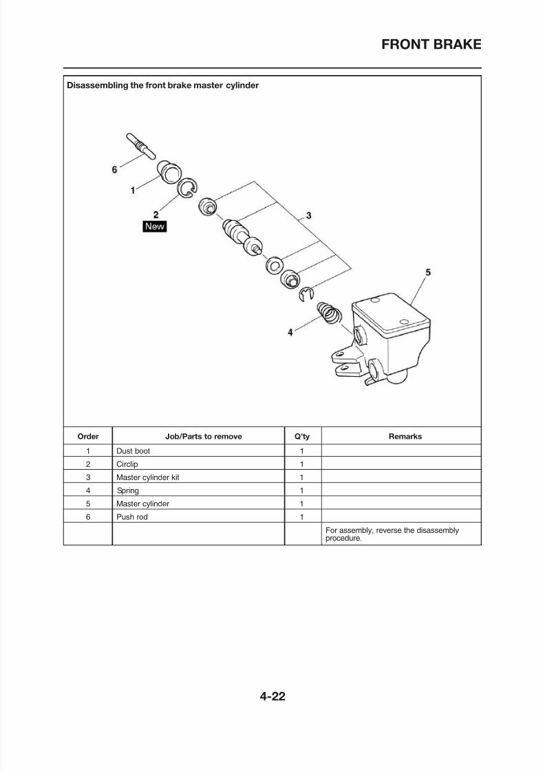
8/12/2019 Yamaha Tenere XT660Z Service Manual
http://slidepdf.com/reader/full/yamaha-tenere-xt660z-service-manual 142/398
Disassembling the front brake master cylinder
FRONT BRAKE
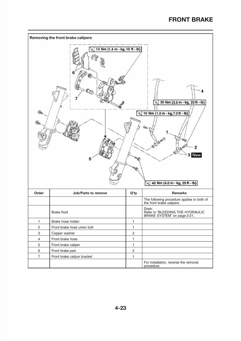
8/12/2019 Yamaha Tenere XT660Z Service Manual
http://slidepdf.com/reader/full/yamaha-tenere-xt660z-service-manual 143/398
Removing the front brake calipers
FRONT BRAKE
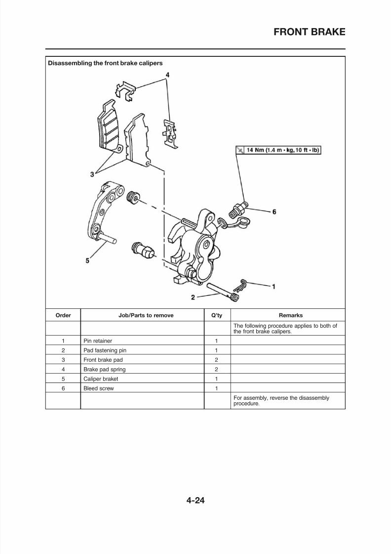
8/12/2019 Yamaha Tenere XT660Z Service Manual
http://slidepdf.com/reader/full/yamaha-tenere-xt660z-service-manual 144/398
Disassembling the front brake calipers
FRONT BRAKE
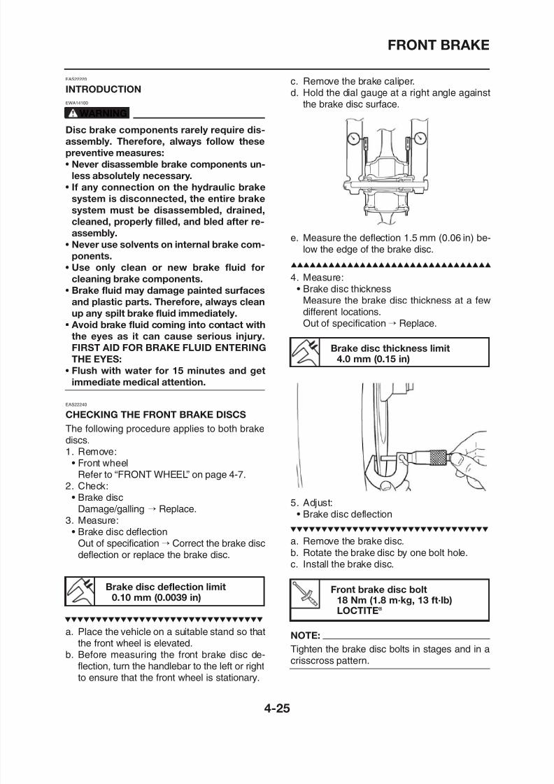
8/12/2019 Yamaha Tenere XT660Z Service Manual
http://slidepdf.com/reader/full/yamaha-tenere-xt660z-service-manual 145/398
EAS22220
INTRODUCTION
EWA14100
WARNING
Disc brake components rarely require dis-
assembly. Therefore, always follow these
preventive measures:
• Never disassemble brake components un-
less absolutely necessary.
• If any connection on the hydraulic brake
system is disconnected, the entire brake
system must be disassembled, drained,cleaned, properly filled, and bled after re-
assembly.
• Never use solvents on internal brake com-
ponents.
• Use only clean or new brake fluid for
cleaning brake components.
• Brake fluid may damage painted surfaces
and plastic parts. Therefore, always cleanup any spilt brake fluid immediately.
• Avoid brake fluid coming into contact with
the eyes as it can cause serious injury.
FIRST AID FOR BRAKE FLUID ENTERING
THE EYES:
• Flush with water for 15 minutes and get
immediate medical attention.
EAS22240
CHECKING THE FRONT BRAKE DISCS
c. Remove the brake caliper.d. Hold the dial gauge at a right angle against
the brake disc surface.
e. Measure the deflection 1.5 mm (0.06 in) be-low the edge of the brake disc.
4. Measure:• Brake disc thickness
Measure the brake disc thickness at a fewdifferent locations.Out of specification→ Replace.
Brake disc thickness limit4.0 mm (0.15 in)
FRONT BRAKE
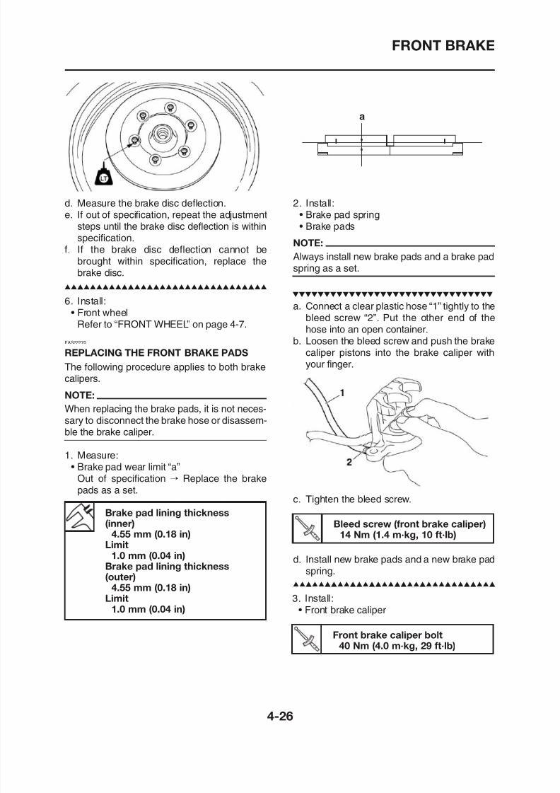
8/12/2019 Yamaha Tenere XT660Z Service Manual
http://slidepdf.com/reader/full/yamaha-tenere-xt660z-service-manual 146/398
d. Measure the brake disc deflection.
e. If out of specification, repeat the adjustmentsteps until the brake disc deflection is withinspecification.
f. If the brake disc deflection cannot bebrought within specification, replace thebrake disc.
6. Install:
• Front wheelRefer to “FRONT WHEEL” on page 4-7.
EAS22270
REPLACING THE FRONT BRAKE PADS
The following procedure applies to both brakecalipers.
NOTE:
When replacing the brake pads, it is not neces-sary to disconnect the brake hose or disassem
2. Install:
• Brake pad spring• Brake pads
NOTE:
Always install new brake pads and a brake padspring as a set.
a
a. Connect a clear plastic hose “1” tightly to thebleed screw “2”. Put the other end of thehose into an open container.
b. Loosen the bleed screw and push the brakecaliper pistons into the brake caliper withyour finger.
FRONT BRAKE
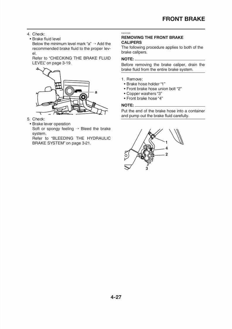
8/12/2019 Yamaha Tenere XT660Z Service Manual
http://slidepdf.com/reader/full/yamaha-tenere-xt660z-service-manual 147/398
4. Check:• Brake fluid level
Below the minimum level mark “a” → Add the
recommended brake fluid to the proper lev-el.Refer to “CHECKING THE BRAKE FLUIDLEVEL” on page 3-19.
5. Check:• Brake lever operation
Soft or spongy feeling → Bleed the brakesystem.Refer to “BLEEDING THE HYDRAULICBRAKE SYSTEM” on page 3-21.
a
EAS22300
REMOVING THE FRONT BRAKE
CALIPERS
The following procedure applies to both of thebrake calipers.
NOTE:
Before removing the brake caliper, drain thebrake fluid from the entire brake system.
1. Remove:• Brake hose holder “1”
• Front brake hose union bolt “2”• Copper washers “3”• Front brake hose “4”
NOTE:
Put the end of the brake hose into a containerand pump out the brake fluid carefully.
FRONT BRAKE
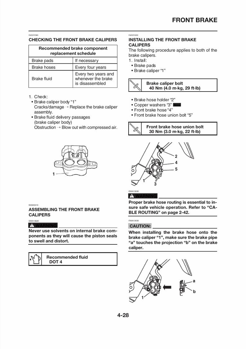
8/12/2019 Yamaha Tenere XT660Z Service Manual
http://slidepdf.com/reader/full/yamaha-tenere-xt660z-service-manual 148/398
EAS22390
CHECKING THE FRONT BRAKE CALIPERS
Recommended brake component
replacement schedule
Brake pads If necessary
Brake hoses Every four years
Every two years andBrake fluid whenever the brake
is disassembled
1. Check:• Brake caliper body “1”
Cracks/damage→ Replace the brake caliperassembly.
• Brake fluid delivery passages(brake caliper body)Obstruction→ Blow out with compressed air.
EAS22450
INSTALLING THE FRONT BRAKE
CALIPERS
The following procedure applies to both of thebrake calipers.1. Install:
• Brake pads• Brake caliper “1”
• Brake hose holder “2”• Copper washers “3”• Front brake hose “4”• Front brake hose union bolt “5”
New
Brake caliper bolt40 Nm (4.0 m·kg, 29 ft·lb)
Front brake hose union bolt30 Nm (3.0 m·kg, 22 ft·lb)
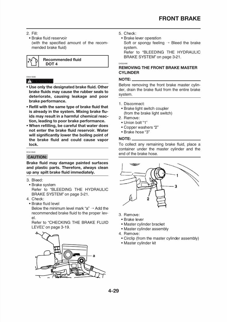
8/12/2019 Yamaha Tenere XT660Z Service Manual
http://slidepdf.com/reader/full/yamaha-tenere-xt660z-service-manual 149/398
FRONT BRAKE
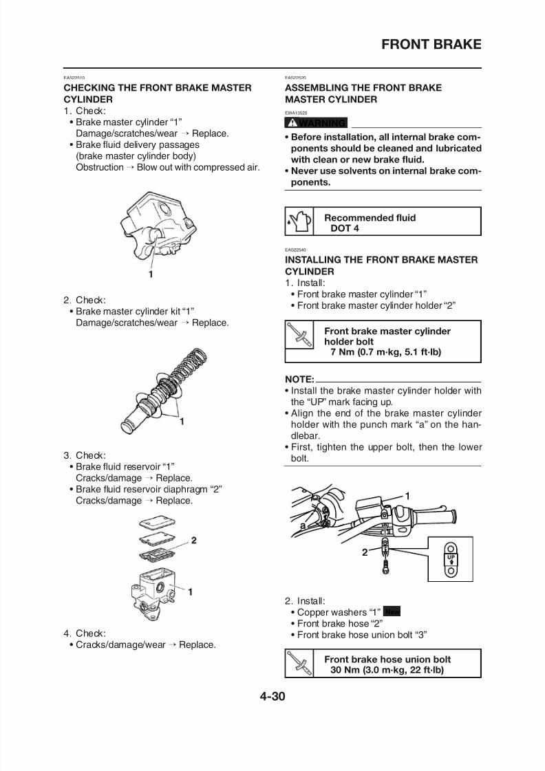
8/12/2019 Yamaha Tenere XT660Z Service Manual
http://slidepdf.com/reader/full/yamaha-tenere-xt660z-service-manual 150/398
EAS22510
CHECKING THE FRONT BRAKE MASTER
CYLINDER
1. Check:• Brake master cylinder “1”
Damage/scratches/wear → Replace.• Brake fluid delivery passages
(brake master cylinder body)Obstruction→ Blow out with compressed air.
2. Check:• Brake master cylinder kit “1”
Damage/scratches/wear → Replace.
Recommended fluidDOT 4
EAS22540
INSTALLING THE FRONT BRAKE MASTER
CYLINDER
1. Install:• Front brake master cylinder “1”
• Front brake master cylinder holder “2”
Front brake master cylinderholder bolt
7 Nm (0.7 m·kg, 5.1 ft·lb)
EAS22520
ASSEMBLING THE FRONT BRAKE
MASTER CYLINDER
EWA13520
WARNING
• Before installation, all internal brake com-
ponents should be cleaned and lubricated
with clean or new brake fluid.
• Never use solvents on internal brake com-
ponents.
NOTE:
• Install the brake master cylinder holder withthe “UP” mark facing up.
FRONT BRAKE
EWA13090
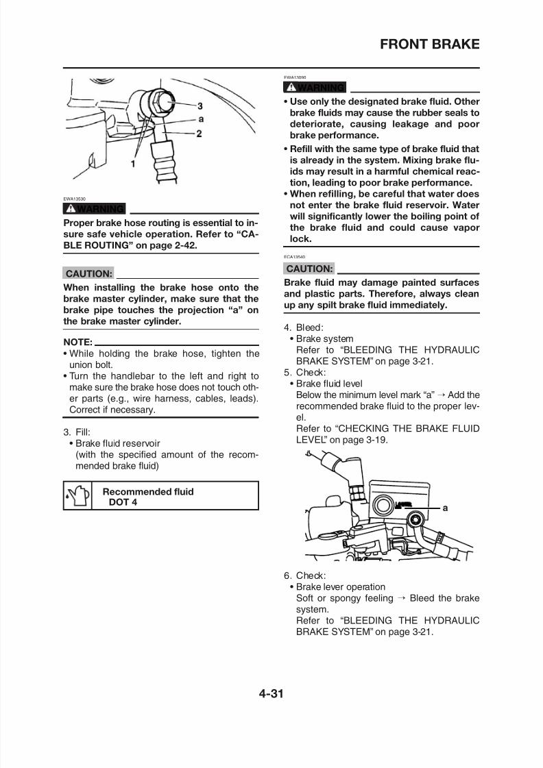
8/12/2019 Yamaha Tenere XT660Z Service Manual
http://slidepdf.com/reader/full/yamaha-tenere-xt660z-service-manual 151/398
EWA13530
WARNING
Proper brake hose routing is essential to in-
sure safe vehicle operation. Refer to “CA-
BLE ROUTING” on page 2-42.
CAUTION:
When installing the brake hose onto the
brake master cylinder, make sure that thebrake pipe touches the projection “a” on
the brake master cylinder.
NOTE:
• While holding the brake hose, tighten theunion bolt.
• Turn the handlebar to the left and right tomake sure the brake hose does not touch oth-
er parts (e.g., wire harness, cables, leads).C t if
EWA13090
WARNING
• Use only the designated brake fluid. Other
brake fluids may cause the rubber seals todeteriorate, causing leakage and poor
brake performance.
• Refill with the same type of brake fluid that
is already in the system. Mixing brake flu-
ids may result in a harmful chemical reac-
tion, leading to poor brake performance.
• When refilling, be careful that water does
not enter the brake fluid reservoir. Waterwill significantly lower the boiling point of
the brake fluid and could cause vapor
lock.
ECA13540
CAUTION:
Brake fluid may damage painted surfaces
and plastic parts. Therefore, always clean
up any spilt brake fluid immediately.
4. Bleed:• Brake system
Refer to “BLEEDING THE HYDRAULICBRAKE SYSTEM” on page 3-21.
5. Check:• Brake fluid level
Below the minimum level mark “a” → Add therecommended brake fluid to the proper lev-
REAR BRAKE
EAS22550
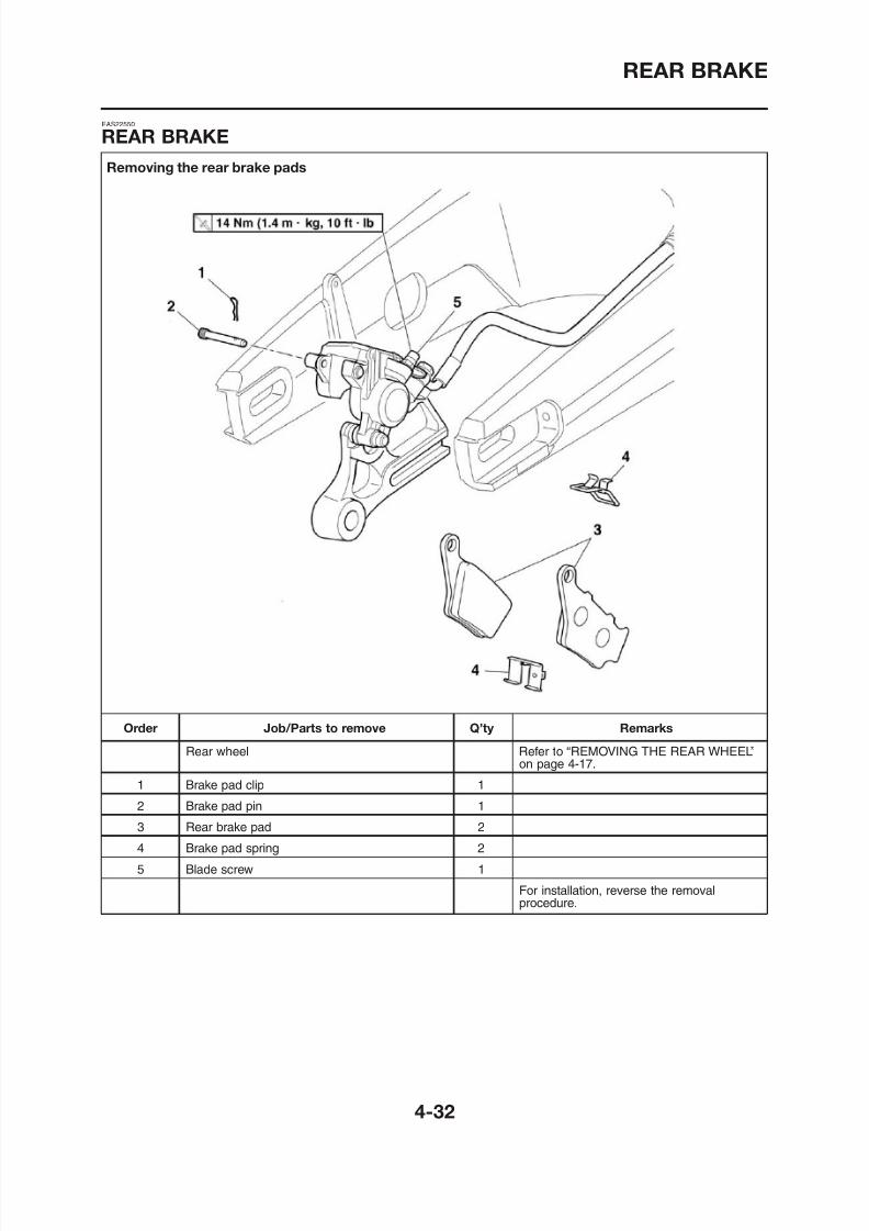
8/12/2019 Yamaha Tenere XT660Z Service Manual
http://slidepdf.com/reader/full/yamaha-tenere-xt660z-service-manual 152/398
Removing the rear brake pads
EAS22550
REAR BRAKE
REAR BRAKE
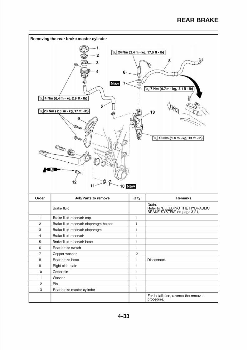
8/12/2019 Yamaha Tenere XT660Z Service Manual
http://slidepdf.com/reader/full/yamaha-tenere-xt660z-service-manual 153/398
Removing the rear brake master cylinder
REAR BRAKE
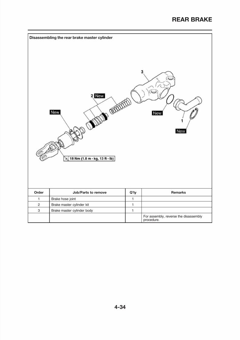
8/12/2019 Yamaha Tenere XT660Z Service Manual
http://slidepdf.com/reader/full/yamaha-tenere-xt660z-service-manual 154/398
Disassembling the rear brake master cylinder
REAR BRAKE
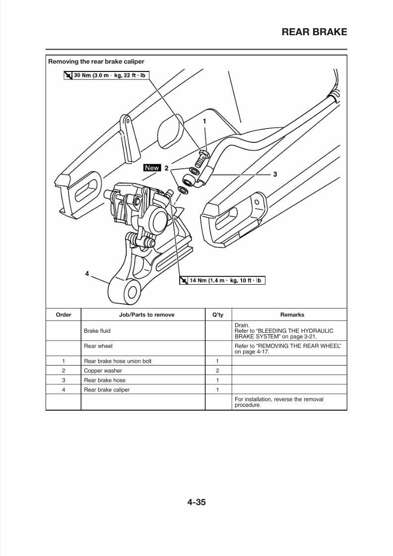
8/12/2019 Yamaha Tenere XT660Z Service Manual
http://slidepdf.com/reader/full/yamaha-tenere-xt660z-service-manual 155/398
Removing the rear brake caliper
REAR BRAKE
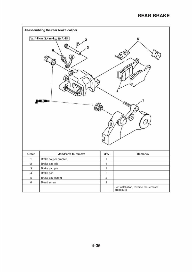
8/12/2019 Yamaha Tenere XT660Z Service Manual
http://slidepdf.com/reader/full/yamaha-tenere-xt660z-service-manual 156/398
Disassembling the rear brake caliper
REAR BRAKE
EAS22560
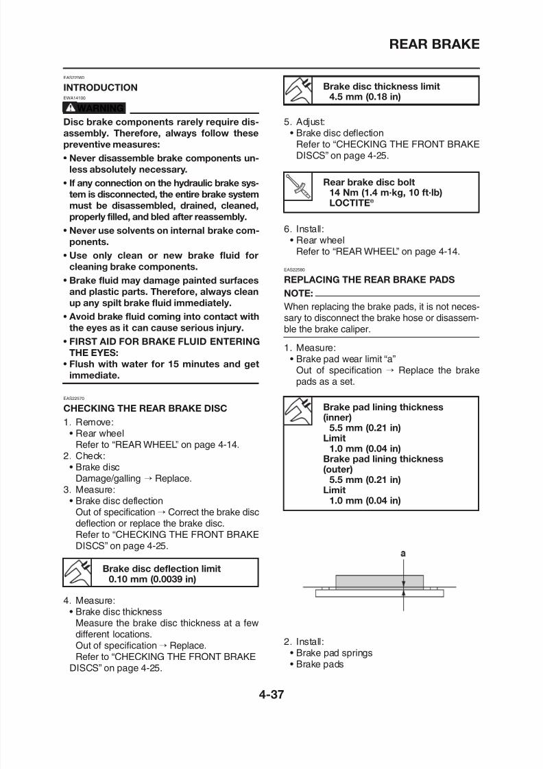
8/12/2019 Yamaha Tenere XT660Z Service Manual
http://slidepdf.com/reader/full/yamaha-tenere-xt660z-service-manual 157/398
INTRODUCTIONEWA14100
WARNINGDisc brake components rarely require dis-
assembly. Therefore, always follow these
preventive measures:
• Never disassemble brake components un-
less absolutely necessary.
• If any connection on the hydraulic brake sys-
tem is disconnected, the entire brake system
must be disassembled, drained, cleaned,properly filled, and bled after reassembly.
• Never use solvents on internal brake com-
ponents.
• Use only clean or new brake fluid for
cleaning brake components.
• Brake fluid may damage painted surfaces
and plastic parts. Therefore, always clean
up any spilt brake fluid immediately.• Avoid brake fluid coming into contact with
the eyes as it can cause serious injury.
• FIRST AID FOR BRAKE FLUID ENTERING
THE EYES:
• Flush with water for 15 minutes and get
immediate.
EAS22570
CHECKING THE REAR BRAKE DISC
Brake disc thickness limit4.5 mm (0.18 in)
5. Adjust:• Brake disc deflection
Refer to “CHECKING THE FRONT BRAKEDISCS” on page 4-25.
Rear brake disc bolt14 Nm (1.4 m·kg, 10 ft·lb)
LOCTITE
®
6. Install:• Rear wheel
Refer to “REAR WHEEL” on page 4-14.
EAS22580
REPLACING THE REAR BRAKE PADS
NOTE:
When replacing the brake pads, it is not neces-sary to disconnect the brake hose or disassem-ble the brake caliper.
1. Measure:• Brake pad wear limit “a”
Out of specification → Replace the brakepads as a set.
Brake pad lining thickness
REAR BRAKE
NOTE: 5 Check:
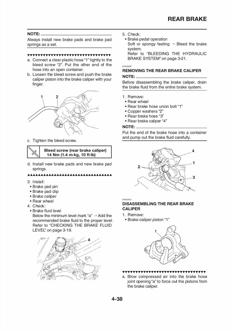
8/12/2019 Yamaha Tenere XT660Z Service Manual
http://slidepdf.com/reader/full/yamaha-tenere-xt660z-service-manual 158/398
NOTE:
Always install new brake pads and brake padsprings as a set.
a. Connect a clear plastic hose “1” tightly to thebleed screw “2”. Put the other end of thehose into an open container.
b. Loosen the bleed screw and push the brakecaliper piston into the brake caliper with yourfinger.
c. Tighten the bleed screw.
Bleed screw (rear brake caliper)14 Nm (1.4 m·kg, 10 ft·lb)
d. Install new brake pads and new brake pad
springs.
5. Check:• Brake pedal operation
Soft or spongy feeling → Bleed the brake
system.Refer to “BLEEDING THE HYDRAULICBRAKE SYSTEM” on page 3-21.
EAS22590
REMOVING THE REAR BRAKE CALIPER
NOTE:
Before disassembling the brake caliper, drainthe brake fluid from the entire brake system.
1. Remove:• Rear wheel• Rear brake hose union bolt “1”• Copper washers “2”• Rear brake hose “3”• Rear brake caliper “4”
NOTE:
Put the end of the brake hose into a containerand pump out the brake fluid carefully.
REAR BRAKE
EWA13550 EWA13610
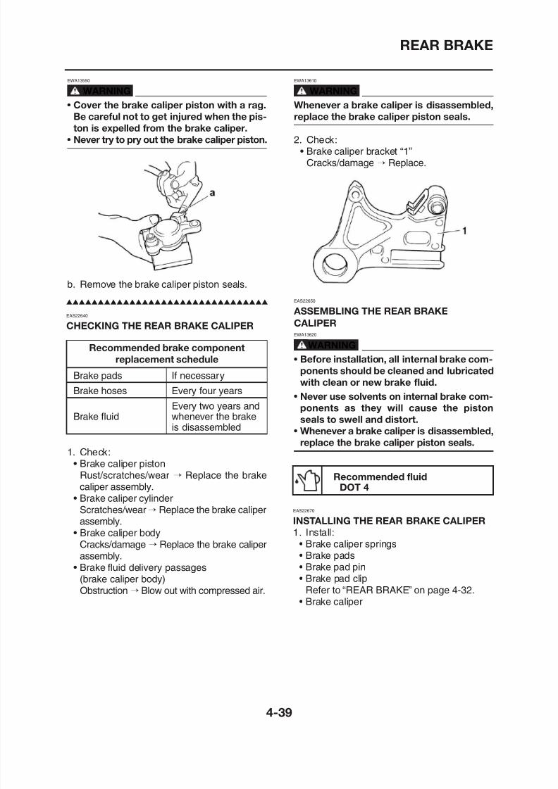
8/12/2019 Yamaha Tenere XT660Z Service Manual
http://slidepdf.com/reader/full/yamaha-tenere-xt660z-service-manual 159/398
WARNING
• Cover the brake caliper piston with a rag.
Be careful not to get injured when the pis-ton is expelled from the brake caliper.
• Never try to pry out the brake caliper piston.
b. Remove the brake caliper piston seals.
EAS22640
CHECKING THE REAR BRAKE CALIPER
Recommended brake component
replacement schedule
Brake pads If necessary
Brake hoses Every four years
Every two years andBrake fluid whenever the brake
WARNING
Whenever a brake caliper is disassembled,
replace the brake caliper piston seals.
2. Check:• Brake caliper bracket “1”
Cracks/damage → Replace.
EAS22650
ASSEMBLING THE REAR BRAKECALIPEREWA13620
WARNING
• Before installation, all internal brake com-
ponents should be cleaned and lubricated
with clean or new brake fluid.
• Never use solvents on internal brake com-
ponents as they will cause the pistonseals to swell and distort
REAR BRAKE
• Rear wheel
• When refilling be careful that water does
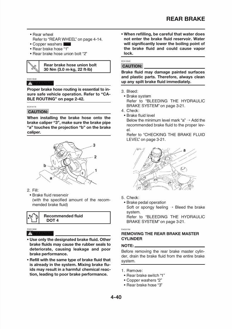
8/12/2019 Yamaha Tenere XT660Z Service Manual
http://slidepdf.com/reader/full/yamaha-tenere-xt660z-service-manual 160/398
• Rear wheelRefer to “REAR WHEEL” on page 4-14.
• Copper washers
• Rear brake hose “1”• Rear brake hose union bolt “2”
New
Rear brake hose union bolt30 Nm (3.0 m·kg, 22 ft·lb)
EWA13530
WARNING
Proper brake hose routing is essential to in-sure safe vehicle operation. Refer to “CA-
BLE ROUTING” on page 2-42.
ECA14170
CAUTION:
When installing the brake hose onto the
brake caliper “3”, make sure the brake pipe
“a” touches the projection “b” on the brake
caliper.
• When refilling, be careful that water does
not enter the brake fluid reservoir. Water
will significantly lower the boiling point of
the brake fluid and could cause vaporlock.
ECA13540
CAUTION:
Brake fluid may damage painted surfaces
and plastic parts. Therefore, always clean
up any spilt brake fluid immediately.
3. Bleed:• Brake system
Refer to “BLEEDING THE HYDRAULICBRAKE SYSTEM” on page 3-21.
4. Check:• Brake fluid level
Below the minimum level mark “a” → Add therecommended brake fluid to the proper lev-
el.Refer to “CHECKING THE BRAKE FLUIDLEVEL” on page 3-21.
REAR BRAKE
NOTE:
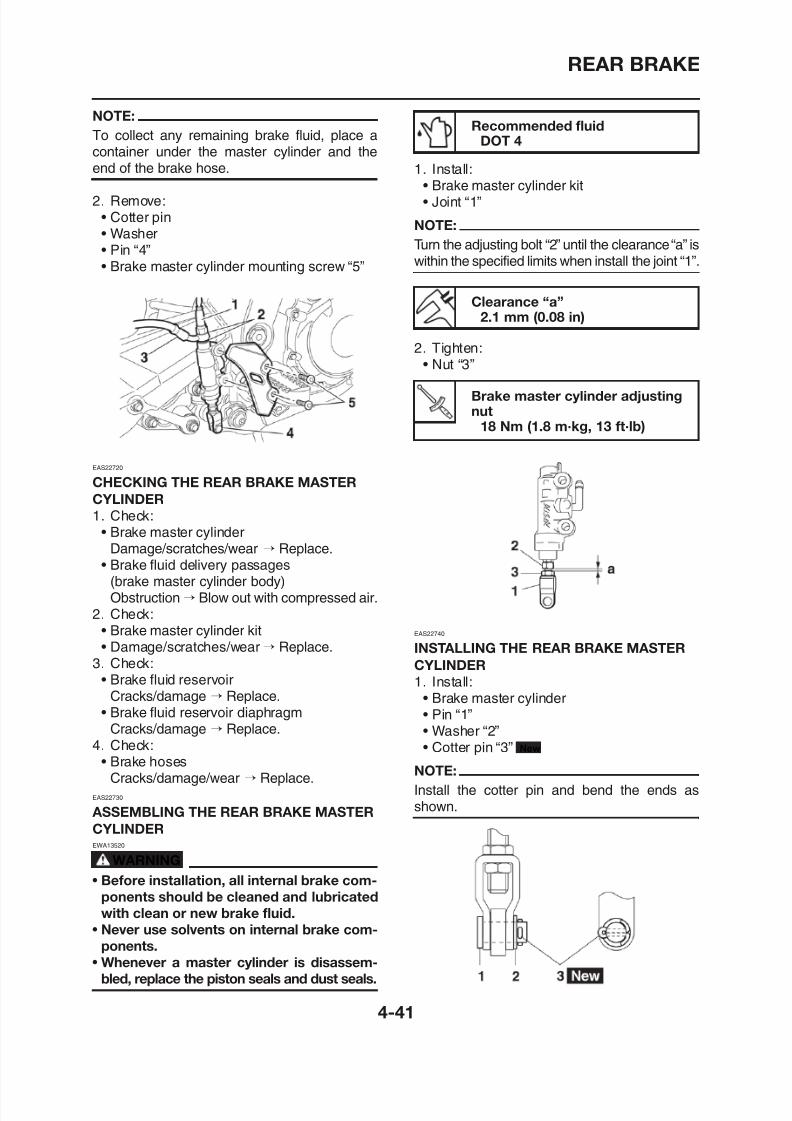
8/12/2019 Yamaha Tenere XT660Z Service Manual
http://slidepdf.com/reader/full/yamaha-tenere-xt660z-service-manual 161/398
NOTE:
To collect any remaining brake fluid, place acontainer under the master cylinder and the
end of the brake hose.
2. Remove:• Cotter pin• Washer• Pin “4”• Brake master cylinder mounting screw “5”
EAS22720
CHECKING THE REAR BRAKE MASTER
CYLINDER
1. Check:• Brake master cylinder
Damage/scratches/wear → Replace.• Brake fluid delivery passages
(brake master cylinder body)Ob t ti Bl t ith d i
Recommended fluidDOT 4
1. Install:• Brake master cylinder kit• Joint “1”
NOTE:
Turn the adjusting bolt “2” until the clearance “a” iswithin the specified limits when install the joint “1”.
Clearance “a”2.1 mm (0.08 in)
2. Tighten:• Nut “3”
Brake master cylinder adjustingnut
18 Nm (1.8 m·kg, 13 ft·lb)
REAR BRAKE
2 Install: EWA13090
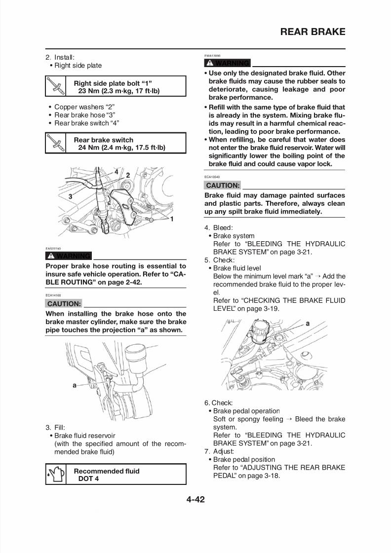
8/12/2019 Yamaha Tenere XT660Z Service Manual
http://slidepdf.com/reader/full/yamaha-tenere-xt660z-service-manual 162/398
Right side plate bolt “1”23 Nm (2.3 m·kg, 17 ft·lb)
Rear brake switch
24 Nm (2.4 m·kg, 17.5 ft·lb)
2. Install:• Right side plate
• Copper washers “2”• Rear brake hose “3”• Rear brake switch “4”
EAS22740
WARNING
Proper brake hose routing is essential to
insure safe vehicle operation. Refer to “CA-
BLE ROUTING” on page 2-42.
WARNING
• Use only the designated brake fluid. Other
brake fluids may cause the rubber seals todeteriorate, causing leakage and poor
brake performance.
• Refill with the same type of brake fluid that
is already in the system. Mixing brake flu-
ids may result in a harmful chemical reac-
tion, leading to poor brake performance.
• When refilling, be careful that water does
not enter the brake fluid reservoir. Water willsignificantly lower the boiling point of the
brake fluid and could cause vapor lock.
ECA13540
CAUTION:
Brake fluid may damage painted surfaces
and plastic parts. Therefore, always clean
up any spilt brake fluid immediately.
4. Bleed:• Brake system
Refer to “BLEEDING THE HYDRAULICBRAKE SYSTEM” on page 3-21.
5. Check:• Brake fluid level
Below the minimum level mark “a” → Add the
recommended brake fluid to the proper lev-el
HANDLEBAR
EAS22840
HANDLEBAR
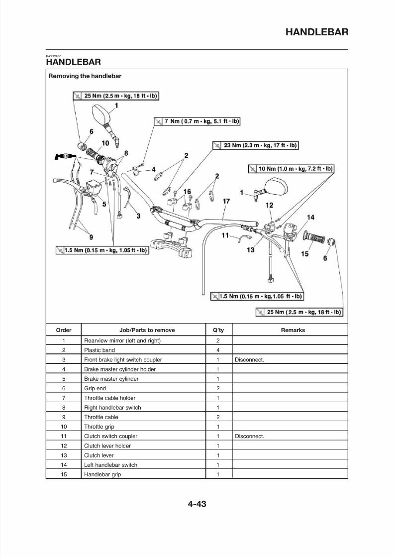
8/12/2019 Yamaha Tenere XT660Z Service Manual
http://slidepdf.com/reader/full/yamaha-tenere-xt660z-service-manual 163/398
Removing the handlebar
HANDLEBAR
HANDLEBAR
R i th h dl b
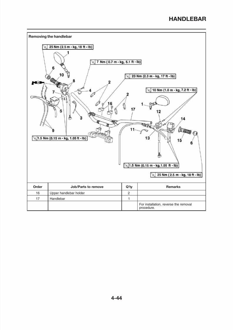
8/12/2019 Yamaha Tenere XT660Z Service Manual
http://slidepdf.com/reader/full/yamaha-tenere-xt660z-service-manual 164/398
Removing the handlebar
HANDLEBAR
EAS22860
H dl b it h b lt
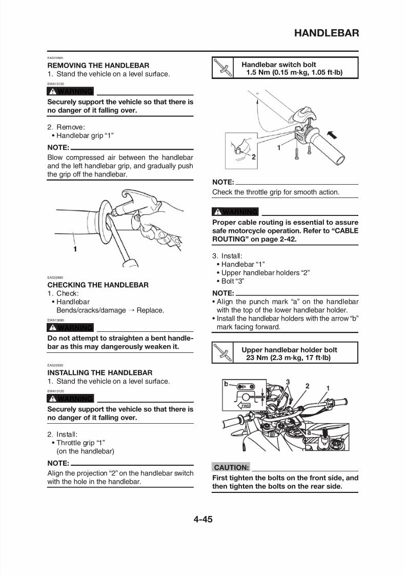
8/12/2019 Yamaha Tenere XT660Z Service Manual
http://slidepdf.com/reader/full/yamaha-tenere-xt660z-service-manual 165/398
REMOVING THE HANDLEBAR
1. Stand the vehicle on a level surface.
EWA13120
WARNING
Securely support the vehicle so that there is
no danger of it falling over.
2. Remove:• Handlebar grip “1”
NOTE:
Blow compressed air between the handlebarand the left handlebar grip, and gradually pushthe grip off the handlebar.
EAS22880
CHECKING THE HANDLEBAR
1. Check:• Handlebar
Handlebar switch bolt1.5 Nm (0.15 m·kg, 1.05 ft·lb)
NOTE:
Check the throttle grip for smooth action.
WARNING
Proper cable routing is essential to assure
safe motorcycle operation. Refer to “CABLE
ROUTING” on page 2-42.
3. Install:• Handlebar “1”• Upper handlebar holders “2”• Bolt “3”
NOTE:
• Align the punch mark “a” on the handlebar
HANDLEBAR
4. Install:
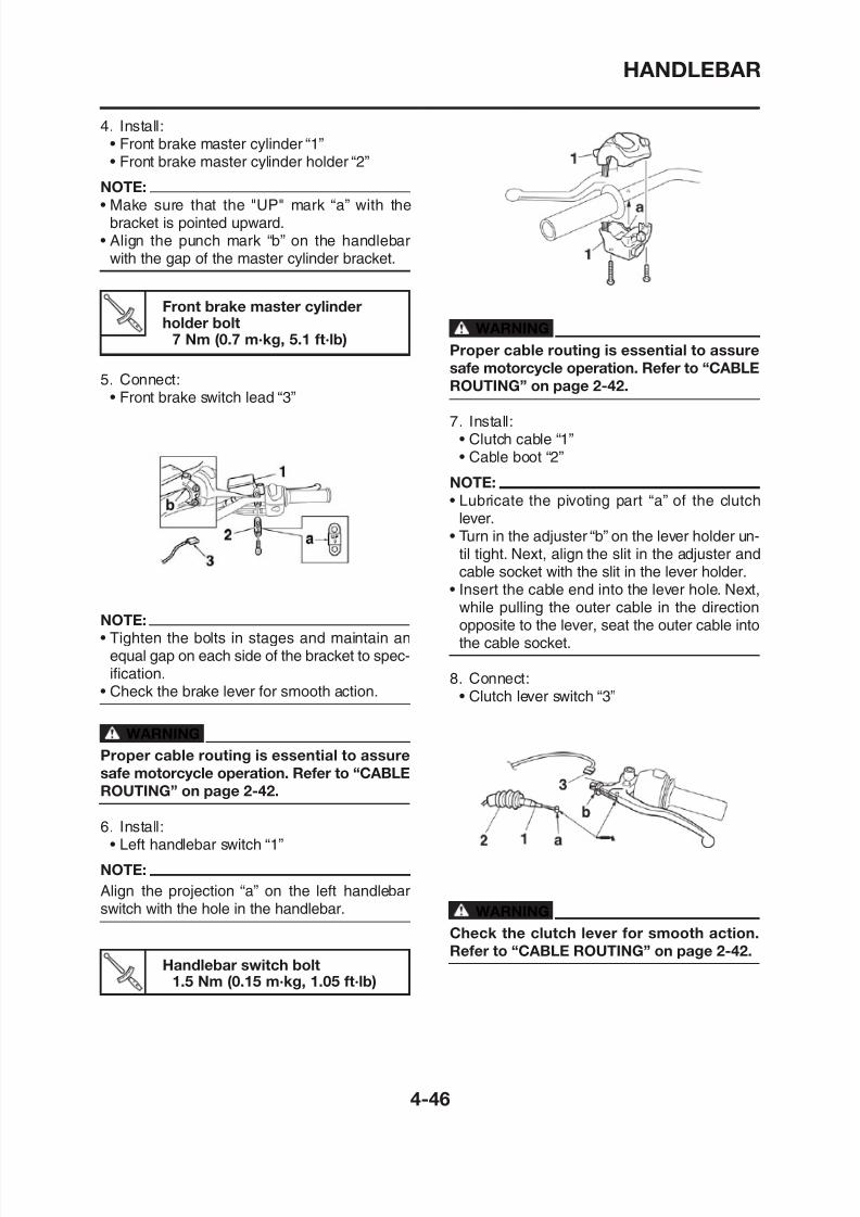
8/12/2019 Yamaha Tenere XT660Z Service Manual
http://slidepdf.com/reader/full/yamaha-tenere-xt660z-service-manual 166/398
• Front brake master cylinder “1”• Front brake master cylinder holder “2”
NOTE:
• Make sure that the "UP" mark “a” with thebracket is pointed upward.
• Align the punch mark “b” on the handlebarwith the gap of the master cylinder bracket.
Front brake master cylinder
holder bolt7 Nm (0.7 m·kg, 5.1 ft·lb)
5. Connect:• Front brake switch lead “3”
NOTE:
• Tighten the bolts in stages and maintain an
WARNINGProper cable routing is essential to assure
safe motorcycle operation. Refer to “CABLE
ROUTING” on page 2-42.
7. Install:• Clutch cable “1”• Cable boot “2”
NOTE:• Lubricate the pivoting part “a” of the clutch
lever.• Turn in the adjuster “b” on the lever holder un-
til tight. Next, align the slit in the adjuster andcable socket with the slit in the lever holder.
• Insert the cable end into the lever hole. Next,while pulling the outer cable in the direction
opposite to the lever, seat the outer cable intothe cable socket
HANDLEBAR
NOTE:9. Install:
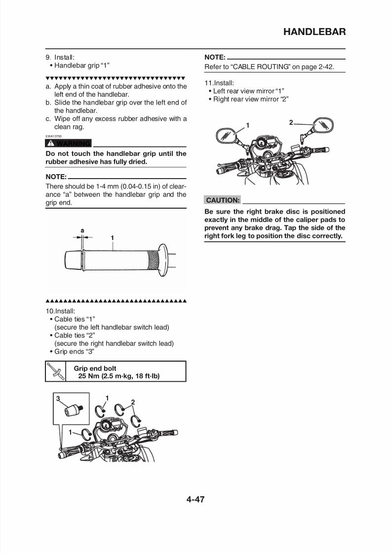
8/12/2019 Yamaha Tenere XT660Z Service Manual
http://slidepdf.com/reader/full/yamaha-tenere-xt660z-service-manual 167/398
Refer to “CABLE ROUTING” on page 2-42.
11.Install:• Left rear view mirror “1”• Right rear view mirror “2”
CAUTION:
Be sure the right brake disc is positioned
exactly in the middle of the caliper pads toprevent any brake drag. Tap the side of the
right fork leg to position the disc correctly.
• Handlebar grip “1”
a. Apply a thin coat of rubber adhesive onto theleft end of the handlebar.
b. Slide the handlebar grip over the left end ofthe handlebar.
c. Wipe off any excess rubber adhesive with aclean rag.
EWA13700
WARNING
Do not touch the handlebar grip until the
rubber adhesive has fully dried.
NOTE:
There should be 1-4 mm (0.04-0.15 in) of clear-ance “a” between the handlebar grip and thegrip end.
FRONT FORK
EAS22950
FRONT FORK
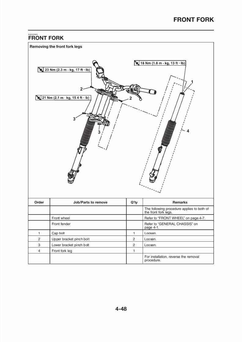
8/12/2019 Yamaha Tenere XT660Z Service Manual
http://slidepdf.com/reader/full/yamaha-tenere-xt660z-service-manual 168/398
Removing the front fork legs
FRONT FORK
FRONT FORK
Disassembling the front fork legs
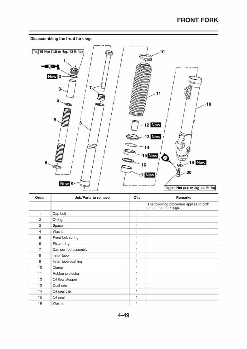
8/12/2019 Yamaha Tenere XT660Z Service Manual
http://slidepdf.com/reader/full/yamaha-tenere-xt660z-service-manual 169/398
Disassembling the front fork legs
FRONT FORK
Disassembling the front fork legs
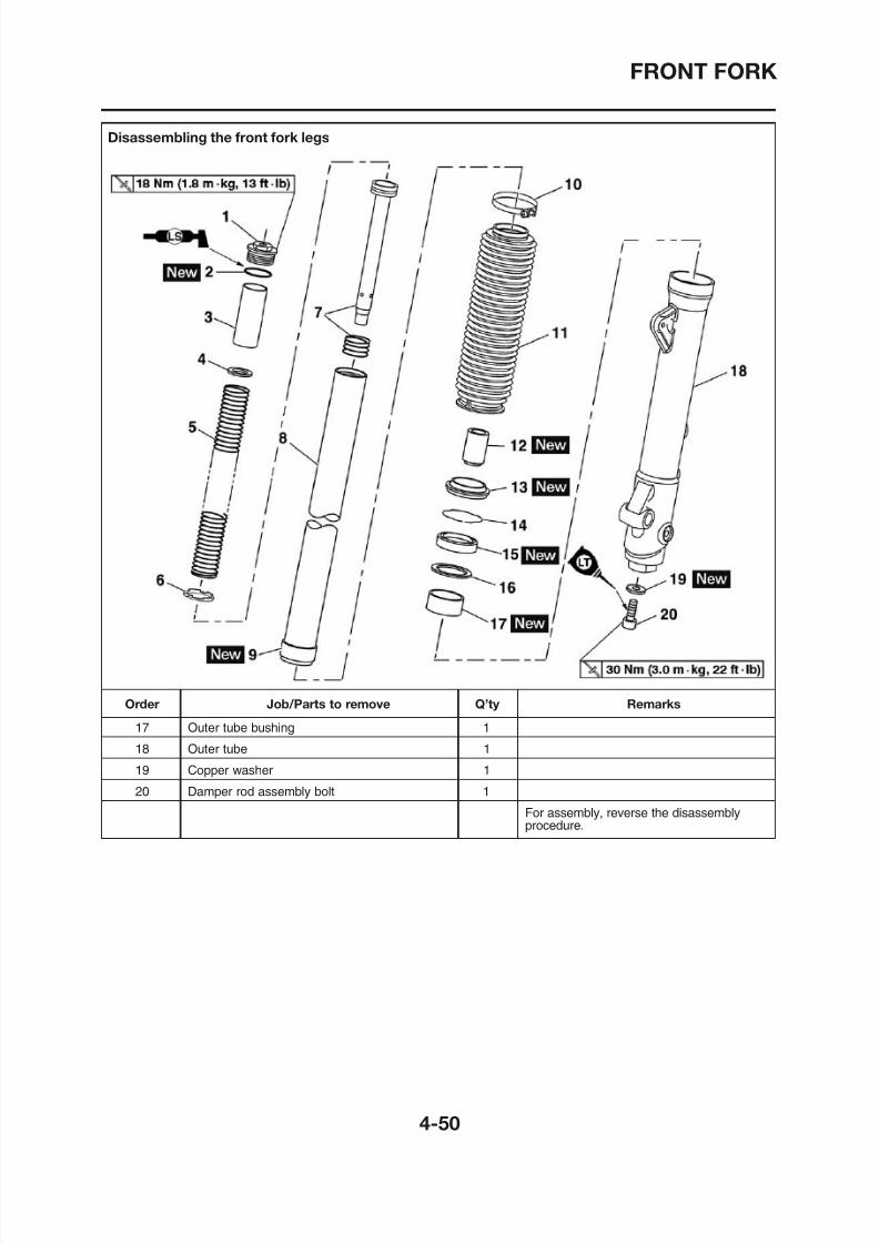
8/12/2019 Yamaha Tenere XT660Z Service Manual
http://slidepdf.com/reader/full/yamaha-tenere-xt660z-service-manual 170/398
Disassembling the front fork legs
FRONT FORK
EAS00649
REMOVING THE FRONT FORK LEGS3. Remove:
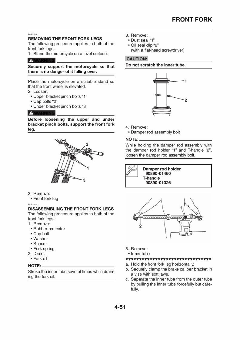
8/12/2019 Yamaha Tenere XT660Z Service Manual
http://slidepdf.com/reader/full/yamaha-tenere-xt660z-service-manual 171/398
REMOVING THE FRONT FORK LEGS
The following procedure applies to both of the
front fork legs.1. Stand the motorcycle on a level surface.
WARNING
Securely support the motorcycle so that
there is no danger of it falling over.
Place the motorcycle on a suitable stand sothat the front wheel is elevated.
2. Loosen:• Upper bracket pinch bolts “1”• Cap bolts “2”• Under bracket pinch bolts “3”
WARNING
Before loosening the upper and under
bracket pinch bolts, support the front fork
leg.
• Dust seal “1”• Oil seal clip “2”
(with a flat-head screwdriver)
CAUTION:
Do not scratch the inner tube.
4. Remove:• Damper rod assembly bolt
NOTE:
While holding the damper rod assembly withthe damper rod holder “1” and T-handle “2”,loosen the damper rod assembly bolt.
Damper rod holder90890-01460
T-handle
FRONT FORK
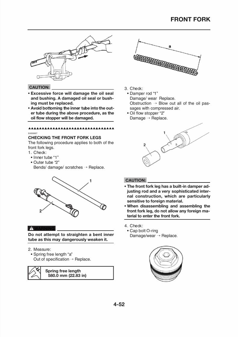
8/12/2019 Yamaha Tenere XT660Z Service Manual
http://slidepdf.com/reader/full/yamaha-tenere-xt660z-service-manual 172/398
CAUTION:
• Excessive force will damage the oil sealand bushing. A damaged oil seal or bush-
ing must be replaced.
• Avoid bottoming the inner tube into the out-
er tube during the above procedure, as the
oil flow stopper will be damaged.
EAS00657
CHECKING THE FRONT FORK LEGS
The following procedure applies to both of thefront fork legs.1. Check:
• Inner tube “1”• Outer tube “2”
Bends/ damage/ scratches → Replace.
3. Check:• Damper rod “1”
Damage/ wear Replace.Obstruction → Blow out all of the oil pas-sages with compressed air.
• Oil flow stopper “2”Damage → Replace.
FRONT FORK
EAS00659
ASSEMBLING THE FRONT FORK LEGS Recommended lubricant
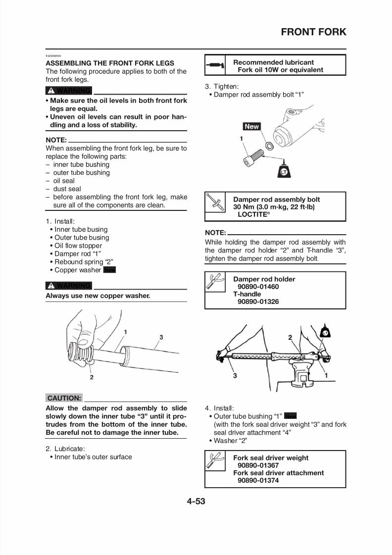
8/12/2019 Yamaha Tenere XT660Z Service Manual
http://slidepdf.com/reader/full/yamaha-tenere-xt660z-service-manual 173/398
ASSEMBLING THE FRONT FORK LEGS
The following procedure applies to both of the
front fork legs.WARNING
• Make sure the oil levels in both front fork
legs are equal.
• Uneven oil levels can result in poor han-
dling and a loss of stability.
NOTE:
When assembling the front fork leg, be sure toreplace the following parts:– inner tube bushing– outer tube bushing– oil seal– dust seal– before assembling the front fork leg, make
sure all of the components are clean.
1. Install:• Inner tube busing• Outer tube busing• Oil flow stopper• Damper rod “1”• Rebound spring “2”• Copper washer
WARNINGAl h
New
Recommended lubricantFork oil 10W or equivalent
3. Tighten:• Damper rod assembly bolt “1”
Damper rod assembly bolt30 Nm (3.0 m·kg, 22 ft·lb)
LOCTITE®
NOTE:
While holding the damper rod assembly withthe damper rod holder “2” and T-handle “3”,tighten the damper rod assembly bolt.
Damper rod holder
90890-01460T-handle
FRONT FORK
NOTE:
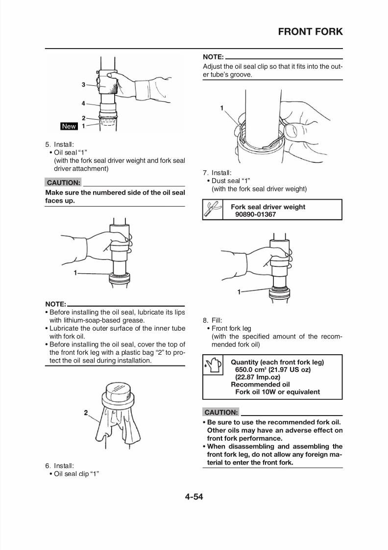
8/12/2019 Yamaha Tenere XT660Z Service Manual
http://slidepdf.com/reader/full/yamaha-tenere-xt660z-service-manual 174/398
5. Install:
• Oil seal “1”(with the fork seal driver weight and fork sealdriver attachment)
CAUTION:
Make sure the numbered side of the oil seal
faces up.
Fork seal driver weight
90890-01367
Adjust the oil seal clip so that it fits into the out-er tube’s groove.
7. Install:• Dust seal “1”
(with the fork seal driver weight)
FRONT FORK
9. Measure:F t f k l il l l “ ”
NOTE:
I t ll th i ith th ll it h “ ” f
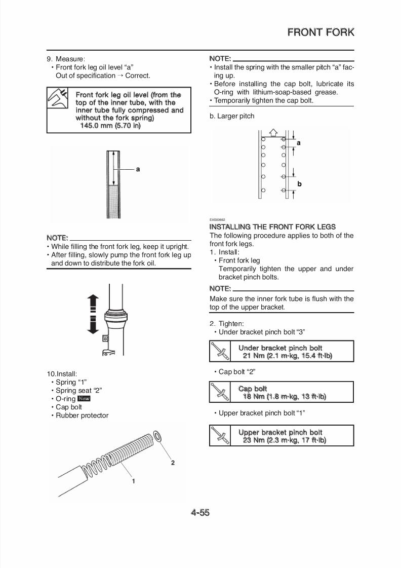
8/12/2019 Yamaha Tenere XT660Z Service Manual
http://slidepdf.com/reader/full/yamaha-tenere-xt660z-service-manual 175/398
Front fork leg oil level (from thetop of the inner tube, with theinner tube fully compressed andwithout the fork spring)
145.0 mm (5.70 in)
• Front fork leg oil level “a”Out of specification → Correct.
NOTE:
• While filling the front fork leg, keep it upright.• After filling, slowly pump the front fork leg up
and down to distribute the fork oil.
• Install the spring with the smaller pitch “a” fac-ing up.
• Before installing the cap bolt, lubricate itsO-ring with lithium-soap-based grease.
• Temporarily tighten the cap bolt.
b. Larger pitch
EAS00662
INSTALLING THE FRONT FORK LEGSThe following procedure applies to both of thefront fork legs.1. Install:
• Front fork legTemporarily tighten the upper and underbracket pinch bolts.
NOTE:
Make sure the inner fork tube is flush with the
FRONT FORK
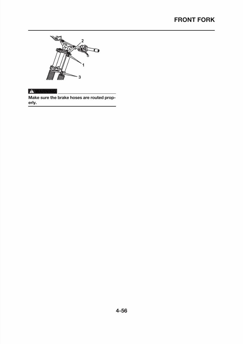
8/12/2019 Yamaha Tenere XT660Z Service Manual
http://slidepdf.com/reader/full/yamaha-tenere-xt660z-service-manual 176/398
WARNING
Make sure the brake hoses are routed prop-
erly.
STEERING HEAD
EAS23090
STEERING HEAD
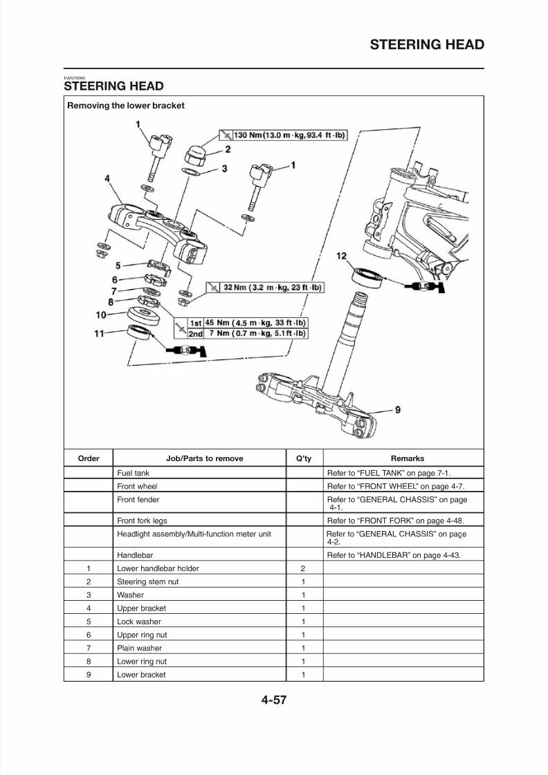
8/12/2019 Yamaha Tenere XT660Z Service Manual
http://slidepdf.com/reader/full/yamaha-tenere-xt660z-service-manual 177/398
Removing the lower bracket
S G
STEERING HEAD
Removing the lower bracket
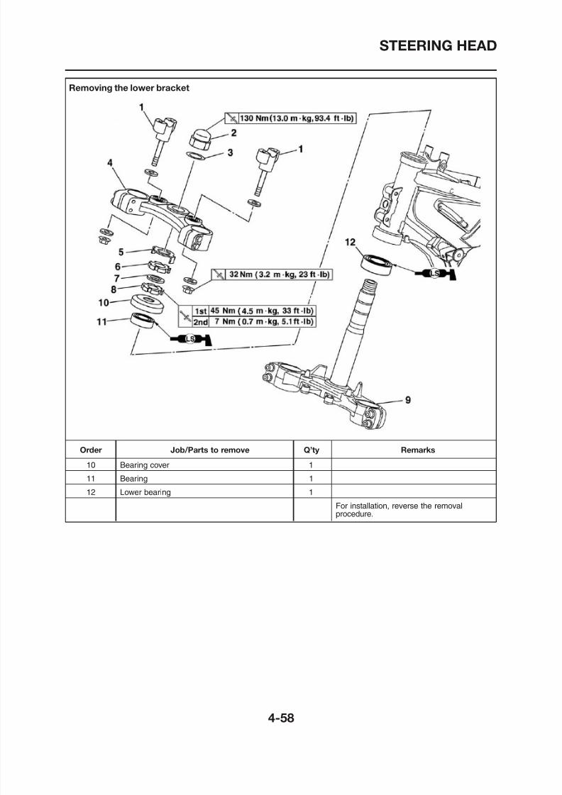
8/12/2019 Yamaha Tenere XT660Z Service Manual
http://slidepdf.com/reader/full/yamaha-tenere-xt660z-service-manual 178/398
STEERING HEAD
EAS00679
REMOVING THE LOWER BRACKET
EAS00681
CHECKING THE STEERING HEAD
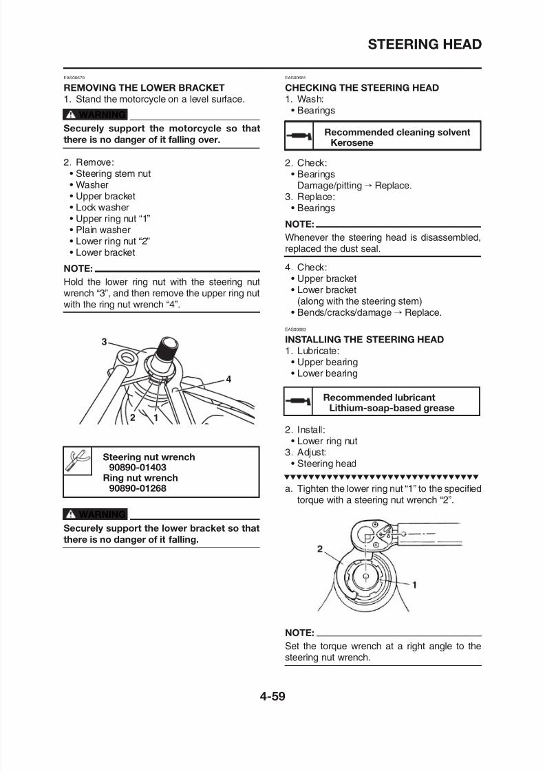
8/12/2019 Yamaha Tenere XT660Z Service Manual
http://slidepdf.com/reader/full/yamaha-tenere-xt660z-service-manual 179/398
REMOVING THE LOWER BRACKET
1. Stand the motorcycle on a level surface.
WARNINGSecurely support the motorcycle so that
there is no danger of it falling over.
2. Remove:• Steering stem nut• Washer• Upper bracket
• Lock washer• Upper ring nut “1”• Plain washer• Lower ring nut “2”• Lower bracket
NOTE:
Hold the lower ring nut with the steering nutwrench “3”, and then remove the upper ring nut
with the ring nut wrench “4”.
3
4
Recommended cleaning solventKerosene
CHECKING THE STEERING HEAD
1. Wash:• Bearings
2. Check:• Bearings
Damage/pitting→ Replace.3. Replace:
• BearingsNOTE:
Whenever the steering head is disassembled,replaced the dust seal.
4. Check:• Upper bracket• Lower bracket
(along with the steering stem)• Bends/cracks/damage→ Replace.
EAS00683
INSTALLING THE STEERING HEAD
1. Lubricate:• Upper bearing• Lower bearing
Recommended lubricantLithium-soap-based grease
STEERING HEAD
Steering nut wrench4. Install:• Upper bracket
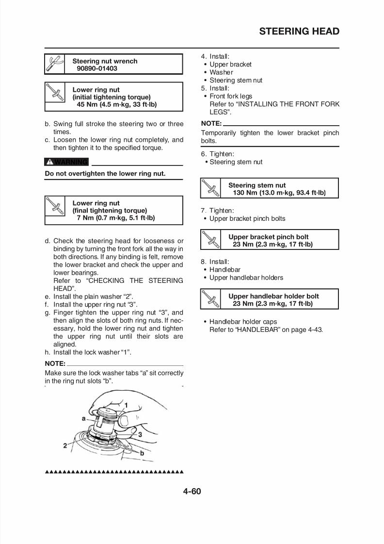
8/12/2019 Yamaha Tenere XT660Z Service Manual
http://slidepdf.com/reader/full/yamaha-tenere-xt660z-service-manual 180/398
Steering stem nut130 Nm (13.0 m·kg, 93.4 ft·lb)
7. Tighten:• Upper bracket pinch bolts
Upper bracket pinch bolt23 Nm (2.3 m·kg, 17 ft·lb)
8. Install:• Handlebar• Upper handlebar holders
b. Swing full stroke the steering two or threetimes.
c. Loosen the lower ring nut completely, and
then tighten it to the specified torque.
WARNING
Do not overtighten the lower ring nut.
d. Check the steering head for looseness orbinding by turning the front fork all the way inboth directions. If any binding is felt, removethe lower bracket and check the upper andlower bearings.
Refer to “CHECKING THE STEERINGHEAD”
g90890-01403
Lower ring nut(initial tightening torque)
45 Nm (4.5 m·kg, 33 ft·lb)
• Upper bracket• Washer
• Steering stem nut5. Install:• Front fork legs
Refer to “INSTALLING THE FRONT FORKLEGS”.
NOTE:
Temporarily tighten the lower bracket pinchbolts.
6. Tighten:• Steering stem nut
Lower ring nut(final tightening torque)
7 Nm (0.7 m·kg, 5.1 ft·lb)
REAR SHOCK ABSORBER ASSEMBLY
EAS23160
REAR SHOCK ABSORBER ASSEMBLY
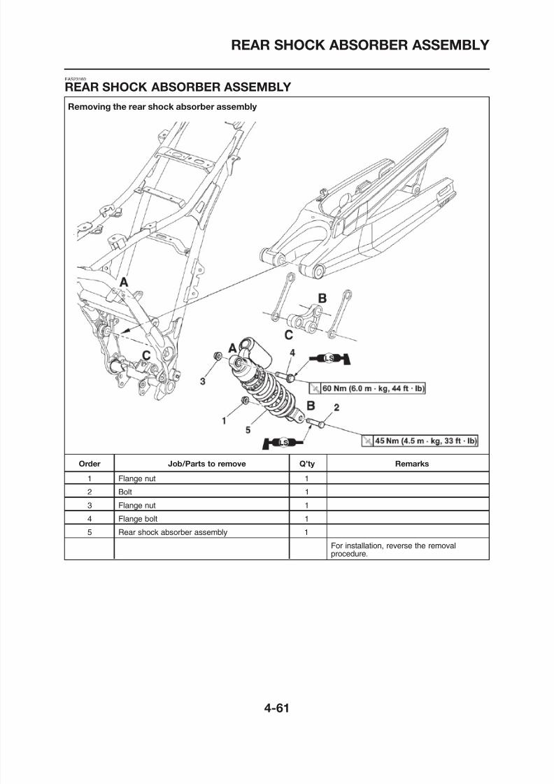
8/12/2019 Yamaha Tenere XT660Z Service Manual
http://slidepdf.com/reader/full/yamaha-tenere-xt660z-service-manual 181/398
Removing the rear shock absorber assembly
REAR SHOCK ABSORBER ASSEMBLY
EAS23180
HANDLING THE REAR SHOCK ABSORBER
EAS23230
REMOVING THE REAR SHOCK
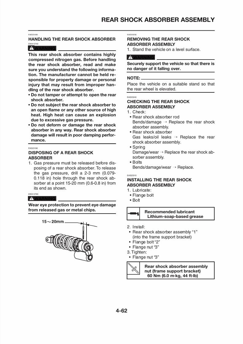
8/12/2019 Yamaha Tenere XT660Z Service Manual
http://slidepdf.com/reader/full/yamaha-tenere-xt660z-service-manual 182/398
EWA13740
WARNING
This rear shock absorber contains highly
compressed nitrogen gas. Before handling
the rear shock absorber, read and make
sure you understand the following informa-
tion. The manufacturer cannot be held re-
sponsible for property damage or personal
injury that may result from improper han-
dling of the rear shock absorber.
• Do not tamper or attempt to open the rearshock absorber.
• Do not subject the rear shock absorber to
an open flame or any other source of high
heat. High heat can cause an explosion
due to excessive gas pressure.
• Do not deform or damage the rear shock
absorber in any way. Rear shock absorber
damage will result in poor damping perfor-mance.
EAS23190
DISPOSING OF A REAR SHOCK
ABSORBER
1. Gas pressure must be released before dis-posing of a rear shock absorber. To releasethe gas pressure, drill a 2-3 mm (0.079-
0.118 in) hole through the rear shock ab-sorber at a point 15 20 mm (0 6 0 8 in) from
ABSORBER ASSEMBLY
1. Stand the vehicle on a level surface.
WARNING
Securely support the vehicle so that there is
no danger of it falling over.
NOTE:
Place the vehicle on a suitable stand so thatthe rear wheel is elevated.
EAS23240
CHECKING THE REAR SHOCK
ABSORBER ASSEMBLY
1. Check:• Rear shock absorber rod
Bends/damage → Replace the rear shockabsorber assembly.
• Rear shock absorber
Gas leaks/oil leaks → Replace the rearshock absorber assembly.
• SpringDamage/wear→ Replace the rear shock ab-sorber assembly.
• BoltsBends/damage/wear → Replace.
EAS23310
INSTALLING THE REAR SHOCK
REAR SHOCK ABSORBER ASSEMBLY
4. Install:• Rear shock absorber assembly “1”
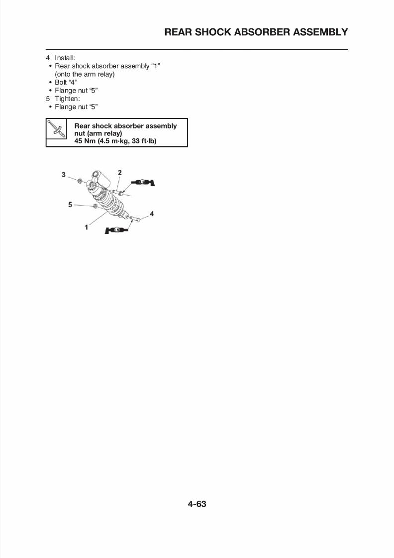
8/12/2019 Yamaha Tenere XT660Z Service Manual
http://slidepdf.com/reader/full/yamaha-tenere-xt660z-service-manual 183/398
Rear shock absorber assembly 1(onto the arm relay)
• Bolt “4”• Flange nut “5”
5. Tighten:• Flange nut “5”
Rear shock absorber assembly nut (arm relay)45 Nm (4.5 m·kg, 33 ft·lb)
SWINGARM
EAS23330
SWINGARM
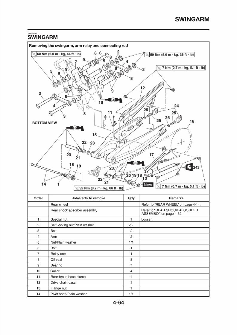
8/12/2019 Yamaha Tenere XT660Z Service Manual
http://slidepdf.com/reader/full/yamaha-tenere-xt660z-service-manual 184/398
Removing the swingarm, arm relay and connecting rod
SWINGARM
Removing the swingarm, arm relay and connecting rod
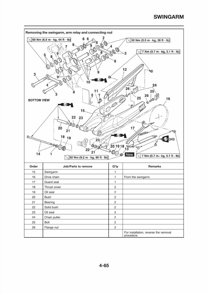
8/12/2019 Yamaha Tenere XT660Z Service Manual
http://slidepdf.com/reader/full/yamaha-tenere-xt660z-service-manual 185/398
SWINGARM
EAS23350
REMOVING THE SWINGARM
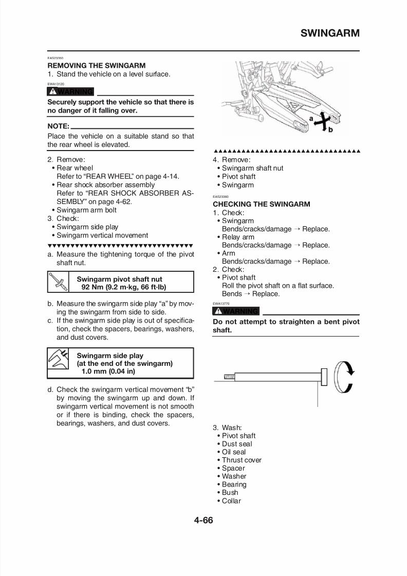
8/12/2019 Yamaha Tenere XT660Z Service Manual
http://slidepdf.com/reader/full/yamaha-tenere-xt660z-service-manual 186/398
1. Stand the vehicle on a level surface.
EWA13120
WARNING
Securely support the vehicle so that there is
no danger of it falling over.
NOTE:
Place the vehicle on a suitable stand so thatthe rear wheel is elevated.
2. Remove:• Rear wheel
Refer to “REAR WHEEL” on page 4-14.• Rear shock absorber assembly
Refer to “REAR SHOCK ABSORBER AS-SEMBLY” on page 4-62.
• Swingarm arm bolt3. Check:
• Swingarm side play• Swingarm vertical movement
a. Measure the tightening torque of the pivotshaft nut.
Swingarm pivot shaft nut92 Nm (9.2 m·kg, 66 ft·lb)
b. Measure the swingarm side play “a” by mov-
4. Remove:• Swingarm shaft nut• Pivot shaft• Swingarm
EAS23360
CHECKING THE SWINGARM
1. Check:• Swingarm
Bends/cracks/damage → Replace.• Relay arm
Bends/cracks/damage → Replace.• Arm
Bends/cracks/damage → Replace.2. Check:
• Pivot shaftRoll the pivot shaft on a flat surface.Bends → Replace.
EWA13770
SWINGARM
Special nut8 N (0 8 k 5 8 ft lb)
Recommended cleaning solventK
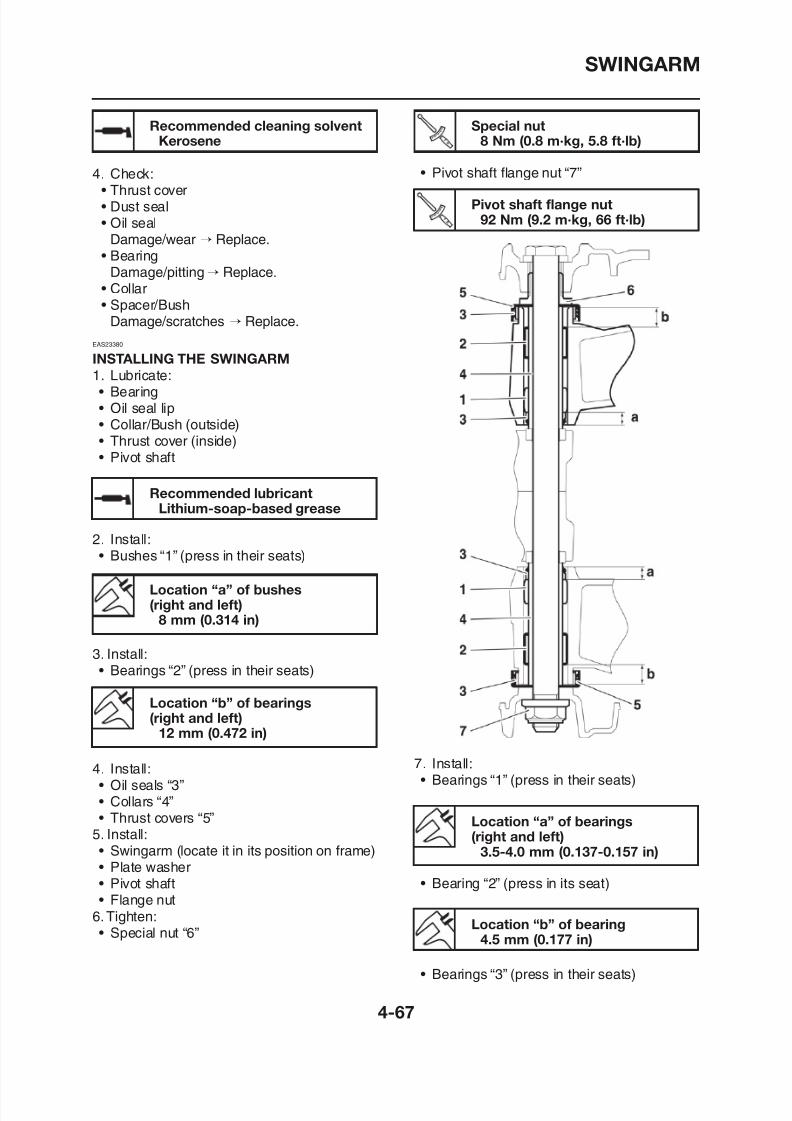
8/12/2019 Yamaha Tenere XT660Z Service Manual
http://slidepdf.com/reader/full/yamaha-tenere-xt660z-service-manual 187/398
• Pivot shaft flange nut “7”4. Check:• Thrust cover• Dust seal• Oil seal
Damage/wear → Replace.• Bearing
Damage/pitting→ Replace.• Collar
• Spacer/BushDamage/scratches → Replace.
EAS23380
INSTALLING THE SWINGARM
1. Lubricate:• Bearing• Oil seal lip• Collar/Bush (outside)
• Thrust cover (inside)• Pivot shaft
2. Install:• Bushes “1” (press in their seats)
Recommended lubricantLithium-soap-based grease
Location “a” of bushes
8 Nm (0.8 m·kg, 5.8 ft·lb)
Pivot shaft flange nut92 Nm (9.2 m·kg, 66 ft·lb)
Kerosene
SWINGARM
Location “c” of bearings(right and left)
10. Install:• Rear shock absorber assembly
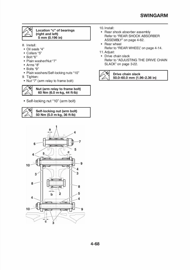
8/12/2019 Yamaha Tenere XT660Z Service Manual
http://slidepdf.com/reader/full/yamaha-tenere-xt660z-service-manual 188/398
8. Install:• Oil seals “4”• Collars “5”• Bolt “6”• Plain washer/Nut “7”• Arms “8”• Bolts “9”
• Plain washers/Self-locking nuts “10”9. Tighten:• Nut “7” (arm relay to frame bolt)
• Self-locking nut “10” (arm bolt)
(right and left)5 mm (0.196 in)
Nut (arm relay to frame bolt)60 Nm (6.0 m·kg, 44 ft·lb)
Self-locking nut (arm bolt)50 Nm (5.0 m·kg, 36 ft·lb)
yRefer to “REAR SHOCK ABSORBER
ASSEMBLY” on page 4-62.• Rear wheel
Refer to “REAR WHEEL” on page 4-14.11.Adjust:• Drive chain slack
Refer to “ADJUSTING THE DRIVE CHAINSLACK” on page 3-22.
Drive chain slack50.0–60.0 mm (1.96–2.36 in)
CHAIN DRIVE
EAS23400
CHAIN DRIVE
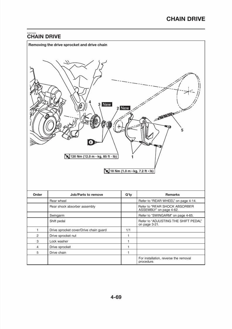
8/12/2019 Yamaha Tenere XT660Z Service Manual
http://slidepdf.com/reader/full/yamaha-tenere-xt660z-service-manual 189/398
Removing the drive sprocket and drive chain
CHAIN DRIVE
EAS23410
REMOVING THE DRIVE CHAIN
1 St d th hi l l l f
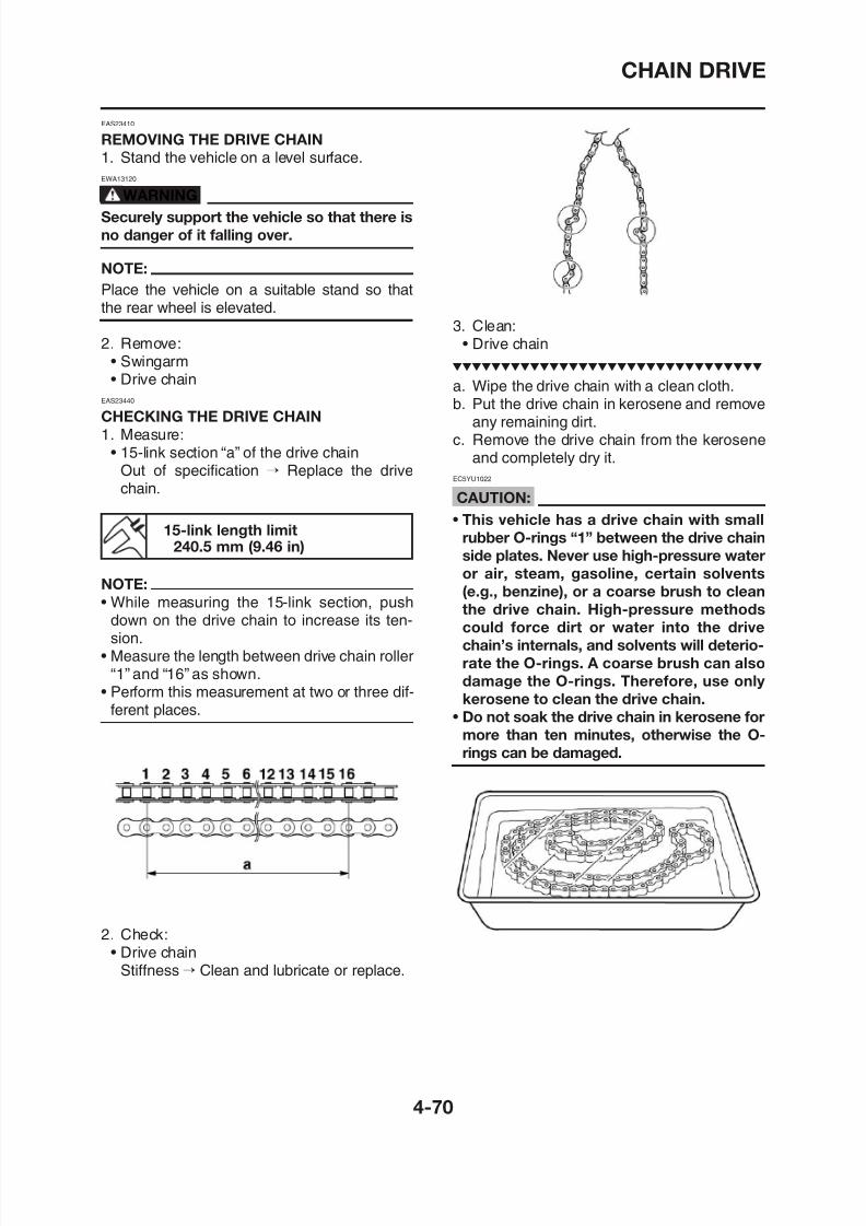
8/12/2019 Yamaha Tenere XT660Z Service Manual
http://slidepdf.com/reader/full/yamaha-tenere-xt660z-service-manual 190/398
1. Stand the vehicle on a level surface.
EWA13120
WARNING
Securely support the vehicle so that there is
no danger of it falling over.
NOTE:
Place the vehicle on a suitable stand so thatthe rear wheel is elevated.
2. Remove:• Swingarm• Drive chain
EAS23440
CHECKING THE DRIVE CHAIN
1. Measure:• 15-link section “a” of the drive chain
Out of specification → Replace the drive
chain.
15-link length limit240.5 mm (9.46 in)
NOTE:
• While measuring the 15-link section, pushdown on the drive chain to increase its ten-
sion.
3. Clean:• Drive chain
a. Wipe the drive chain with a clean cloth.b. Put the drive chain in kerosene and remove
any remaining dirt.c. Remove the drive chain from the kerosene
and completely dry it.
EC5YU1022
CAUTION:
• This vehicle has a drive chain with small
rubber O-rings “1” between the drive chain
side plates. Never use high-pressure water
or air, steam, gasoline, certain solvents
(e.g., benzine), or a coarse brush to clean
the drive chain. High-pressure methods
could force dirt or water into the drive
chain’s internals, and solvents will deterio-
CHAIN DRIVE
3. Remove:• Drive sprocket nut “1”
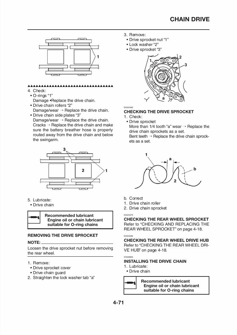
8/12/2019 Yamaha Tenere XT660Z Service Manual
http://slidepdf.com/reader/full/yamaha-tenere-xt660z-service-manual 191/398
4. Check:• O-rings “1”Damage •Replace the drive chain.
• Drive chain rollers “2”Damage/wear → Replace the drive chain.
• Drive chain side plates “3”Damage/wear → Replace the drive chain.Cracks→ Replace the drive chain and makesure the battery breather hose is properly
routed away from the drive chain and belowthe swingarm.
• Lock washer “2”
• Drive sprocket “3”
EAS23460
CHECKING THE DRIVE SPROCKET
1. Check:• Drive sprocket
More than 1/4 tooth “a” wear→ Replace the
drive chain sprockets as a set.Bent teeth → Replace the drive chain sprock-ets as a set.
12
3
a
CHAIN DRIVE
2. Install:• Drive sprocket “1”
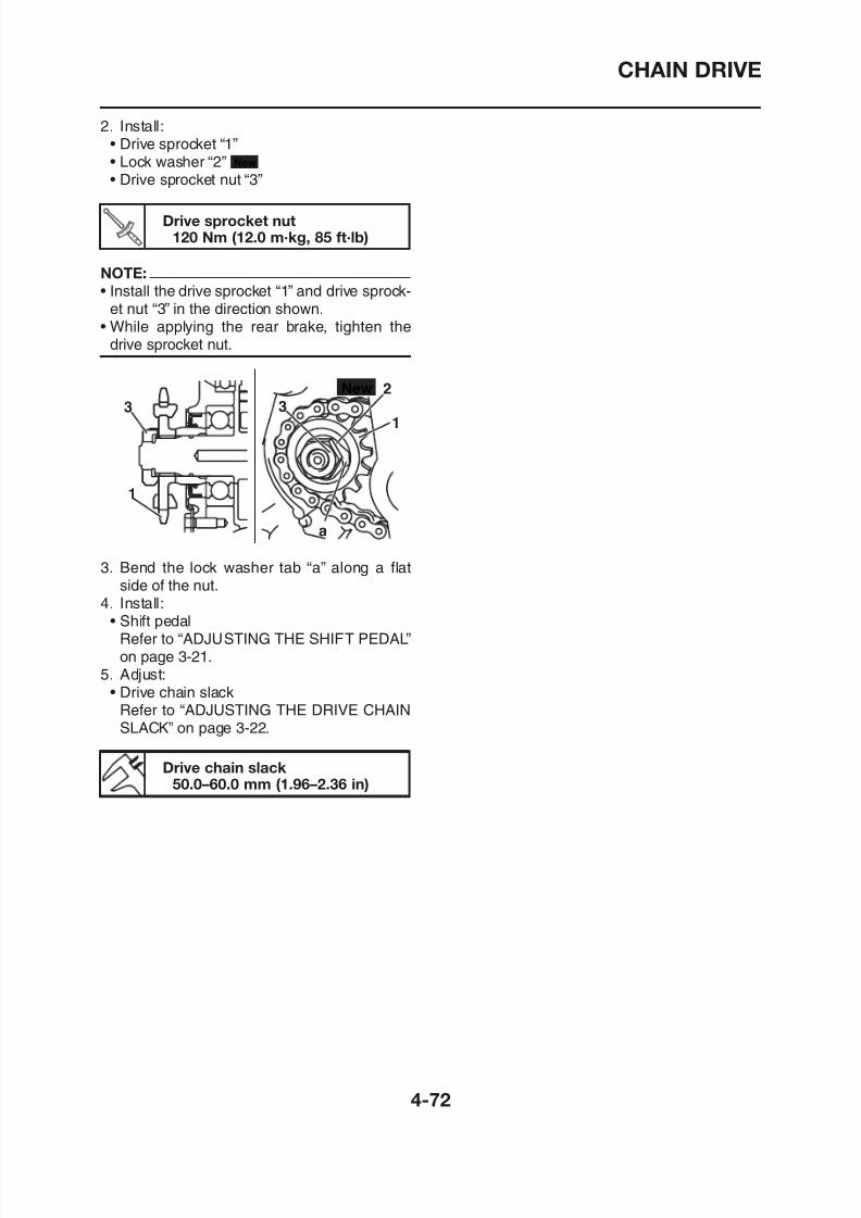
8/12/2019 Yamaha Tenere XT660Z Service Manual
http://slidepdf.com/reader/full/yamaha-tenere-xt660z-service-manual 192/398
• Lock washer “2”
• Drive sprocket nut “3”
New
Drive sprocket nut120 Nm (12.0 m·kg, 85 ft·lb)
NOTE:
• Install the drive sprocket “1” and drive sprock-et nut “3” in the direction shown.
• While applying the rear brake, tighten thedrive sprocket nut.
3. Bend the lock washer tab “a” along a flatside of the nut.
4. Install:• Shift pedal
Refer to “ADJUSTING THE SHIFT PEDAL”
New
3
1
3
2
1
a
ENGINE
8/12/2019 Yamaha Tenere XT660Z Service Manual
http://slidepdf.com/reader/full/yamaha-tenere-xt660z-service-manual 193/398
ENGINE REMOVAL........................................................................................ 5-1INSTALLING THE ENGINE ...................................................................... 5-7
CYLINDER HEAD........................................................................................... 5-8
REMOVING THE CYLINDER HEAD........................................................ 5-9
CHECKING THE CYLINDER HEAD ........................................................ 5-9
CHECKING THE TAPPET COVERS AND CAMSHAFTSPROCKET COVER ................................................................................5-10
CHECKING THE TIMING CHAIN TENSIONER.......................................5-10CHECKING THE CAMSHAFT SPROCKET.............................................5-11
INSTALLING THE CYLINDER HEAD.......................................................5-11
ROCKER ARMS AND CAMSHAFT ...............................................................5-14
REMOVING THE ROCKER ARMS AND CAMSHAFT.............................5-15
CHECKING THE CAMSHAFT..................................................................5-15
CHECKING THE DECOMPRESSION SYSTEM......................................5-16
CHECKING THE ROCKER ARMS AND ROCKER ARM SHAFTS .........5-16
INSTALLING THE CAMSHAFT AND ROCKER ARMS............................5-17
VALVES AND VALVE SPRINGS .....................................................................5-19REMOVING THE VALVES ........................................................................5-20CHECKING THE VALVES AND VALVE GUIDES.....................................5-20CHECKING THE VALVE SEATS ..............................................................5-22CHECKING THE VALVE SPRINGS..........................................................5-23
INSTALLING THE VALVES.......................................................................5-24
5
OIL PUMP.......................................................................................................5-40
CHECKING THE OIL PUMP ....................................................................5-43
8/12/2019 Yamaha Tenere XT660Z Service Manual
http://slidepdf.com/reader/full/yamaha-tenere-xt660z-service-manual 194/398
CHECKING THE OIL DELIVERY PIPES AND HOSES ...........................5-43
ASSEMBLING THE OIL PUMP................................................................5-44INSTALLING THE OIL PUMP...................................................................5-44
BALANCER DRIVEN GEAR...........................................................................5-45
REMOVING THE BALANCER DRIVEN GEAR ANDBALANCER DRIVE GEAR.......................................................................5-46
CHECKING THE BALANCER DRIVEN GEAR, WATER PUMPDRIVE GEAR, PRIMARY DRIVE GEAR, AND BALANCER
DRIVE GEAR............................................................................................5-46INSTALLING THE BALANCER DRIVEN GEAR ANDBALANCER DRIVE GEAR.......................................................................5-46
SHIFT SHAFT .................................................................................................5-48
SHIFT SHAFT AND STOPPER LEVER...................................................5-48
CHECKING THE SHIFT SHAFT ..............................................................5-50
CHECKING THE STOPPER LEVER........................................................5-50
INSTALLING THE SHIFT SHAFT.............................................................5-50
STARTER CLUTCH AND A.C. MAGNETO ...................................................5-51REMOVING THE A.C. MAGNETO ROTOR..............................................5-53CHECKING THE STATOR COIL AND CRANKSHAFTPOSITION SENSOR ................................................................................5-53CHECKING THE STARTER CLUTCH......................................................5-54CHECKING THE TORQUE LIMITER .......................................................5-54INSTALLING THE A.C. MAGNETO ROTOR.............................................5-54
ENGINE REMOVAL
EAS23710
ENGINE REMOVAL
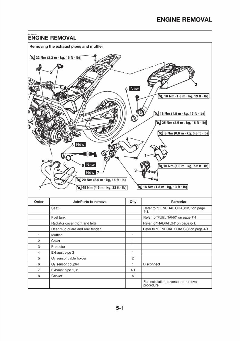
8/12/2019 Yamaha Tenere XT660Z Service Manual
http://slidepdf.com/reader/full/yamaha-tenere-xt660z-service-manual 195/398
Removing the exhaust pipes and muffler
ENGINE REMOVAL
Removing the oil pipes
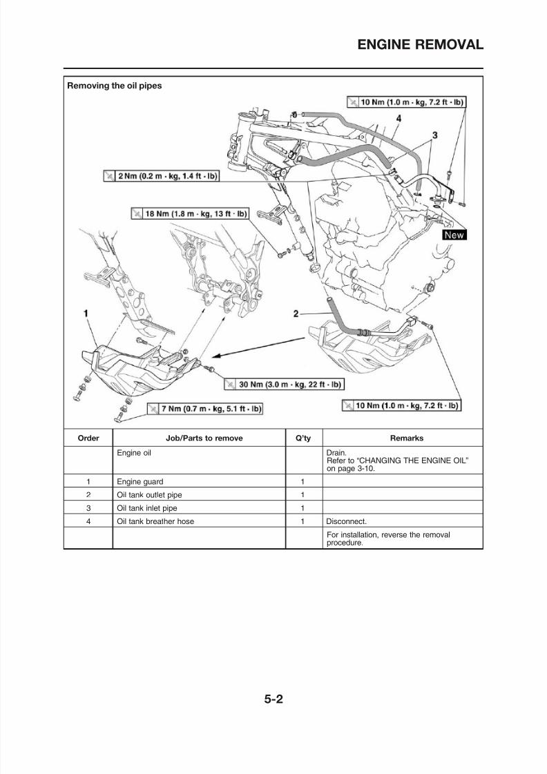
8/12/2019 Yamaha Tenere XT660Z Service Manual
http://slidepdf.com/reader/full/yamaha-tenere-xt660z-service-manual 196/398
ENGINE REMOVAL
Removing the leads, cables, hoses, and ignition coil
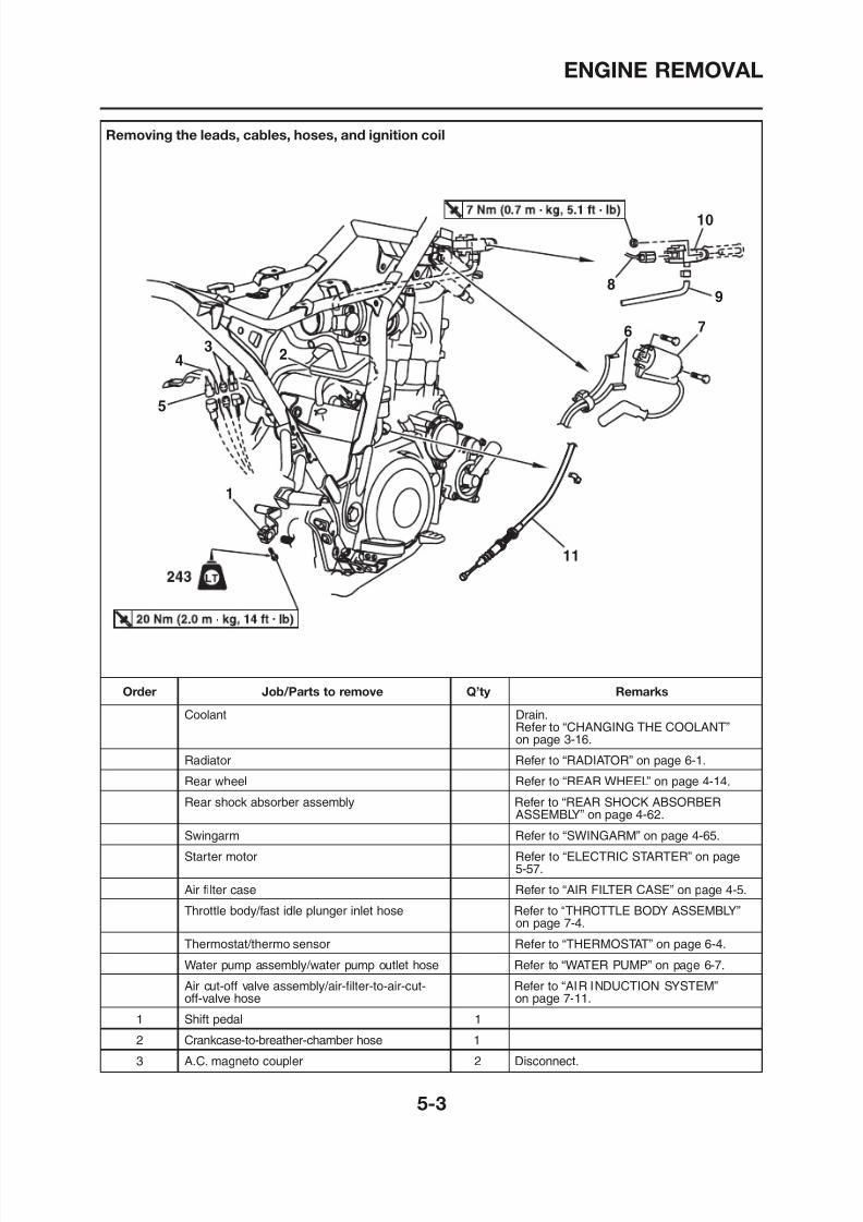
8/12/2019 Yamaha Tenere XT660Z Service Manual
http://slidepdf.com/reader/full/yamaha-tenere-xt660z-service-manual 197/398
ENGINE REMOVAL
Removing the leads, cables, hoses, and ignition coil
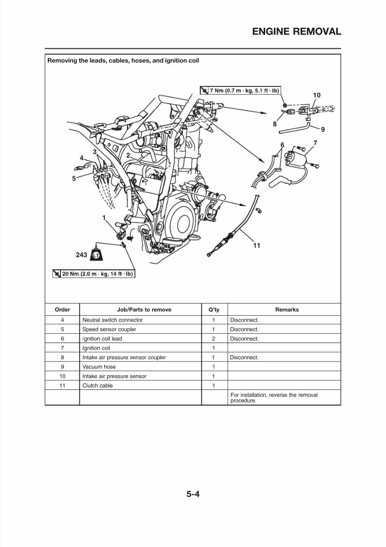
8/12/2019 Yamaha Tenere XT660Z Service Manual
http://slidepdf.com/reader/full/yamaha-tenere-xt660z-service-manual 198/398
ENGINE REMOVAL
Removing the engine
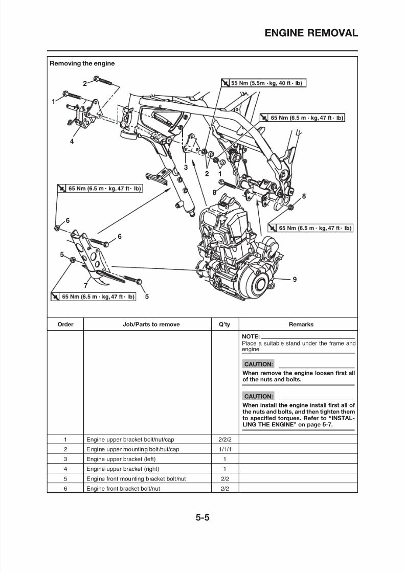
8/12/2019 Yamaha Tenere XT660Z Service Manual
http://slidepdf.com/reader/full/yamaha-tenere-xt660z-service-manual 199/398
ENGINE REMOVAL
Removing the engine
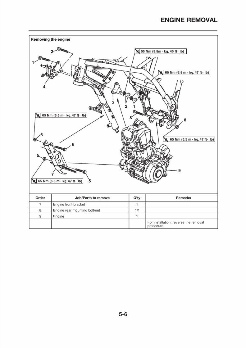
8/12/2019 Yamaha Tenere XT660Z Service Manual
http://slidepdf.com/reader/full/yamaha-tenere-xt660z-service-manual 200/398
ENGINE REMOVAL
EAS00192
INSTALLING THE ENGINE
1 Install:
3. Tighten:• Engine rear mounting bolt/nut “1”• Engine front bracket bolt/nut (upper) “3”
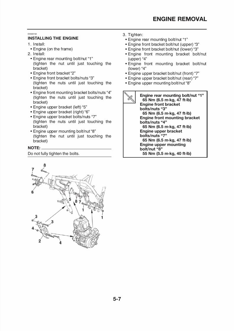
8/12/2019 Yamaha Tenere XT660Z Service Manual
http://slidepdf.com/reader/full/yamaha-tenere-xt660z-service-manual 201/398
1. Install:
• Engine (on the frame)2. Install:• Engine rear mounting bolt/nut “1”
(tighten the nut until just touching thebracket)
• Engine front bracket “2”• Engine front bracket bolts/nuts “3”
(tighten the nuts until just touching thebracket)
• Engine front mounting bracket bolts/nuts “4”(tighten the nuts until just touching thebracket)
• Engine upper bracket (left) “5”• Engine upper bracket (right) “6”• Engine upper bracket bolts/nuts “7”
(tighten the nuts until just touching thebracket)
• Engine upper mounting bolt/nut “8”(tighten the nut until just touching thebracket)
NOTE:
Do not fully tighten the bolts.
• Engine front bracket bolt/nut (upper) 3
• Engine front bracket bolt/nut (lower) “3”• Engine front mounting bracket bolt/nut(upper) “4”
• Engine front mounting bracket bolt/nut(lower) “4”
• Engine upper bracket bolt/nut (front) “7”• Engine upper bracket bolt/nut (rear) “7”• Engine upper mounting bolt/nut “8”
Engine rear mounting bolt/nut “1”65 Nm (6.5 m·kg, 47 ft·lb)
Engine front bracketbolts/nuts “3”
65 Nm (6.5 m·kg, 47 ft·lb)Engine front mounting bracketbolts/nuts “4”
65 Nm (6.5 m·kg, 47 ft·lb)
Engine upper bracketbolts/nuts “7”65 Nm (6.5 m·kg, 47 ft·lb)
Engine upper mountingbolt/nut “8”
55 Nm (5.5 m·kg, 40 ft·lb)
CYLINDER HEAD
R i th li d h d
EAS00221
CYLINDER HEAD
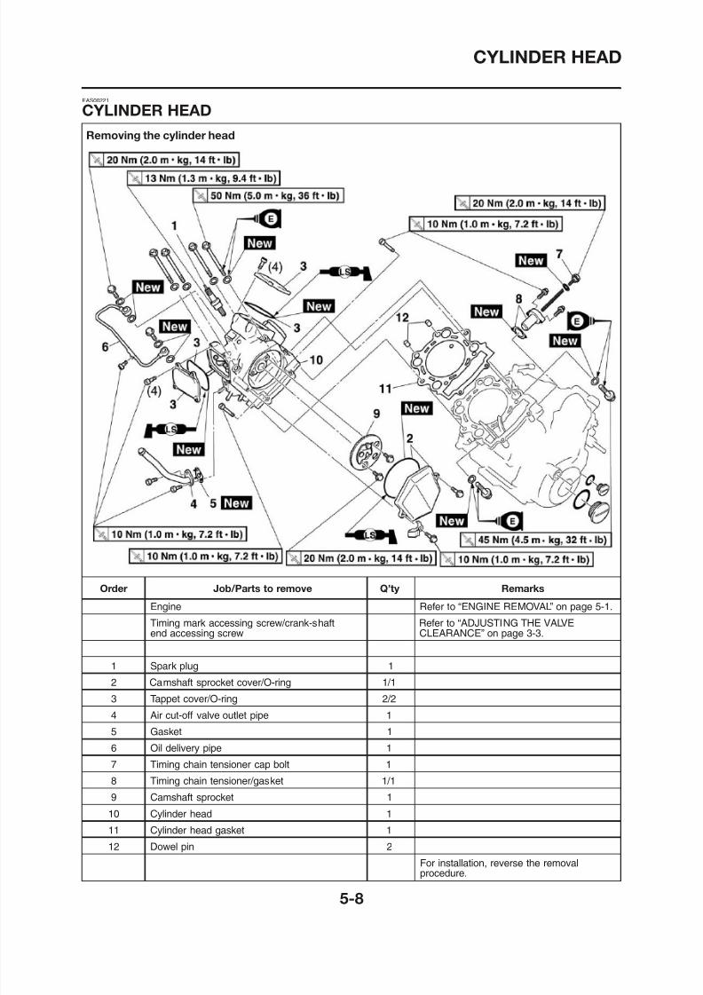
8/12/2019 Yamaha Tenere XT660Z Service Manual
http://slidepdf.com/reader/full/yamaha-tenere-xt660z-service-manual 202/398
Removing the cylinder head
CYLINDER HEAD
EAS00225
REMOVING THE CYLINDER HEAD
1 Align:
3. Loosen:• Timing chain tensioner cap bolt
4 Remove:
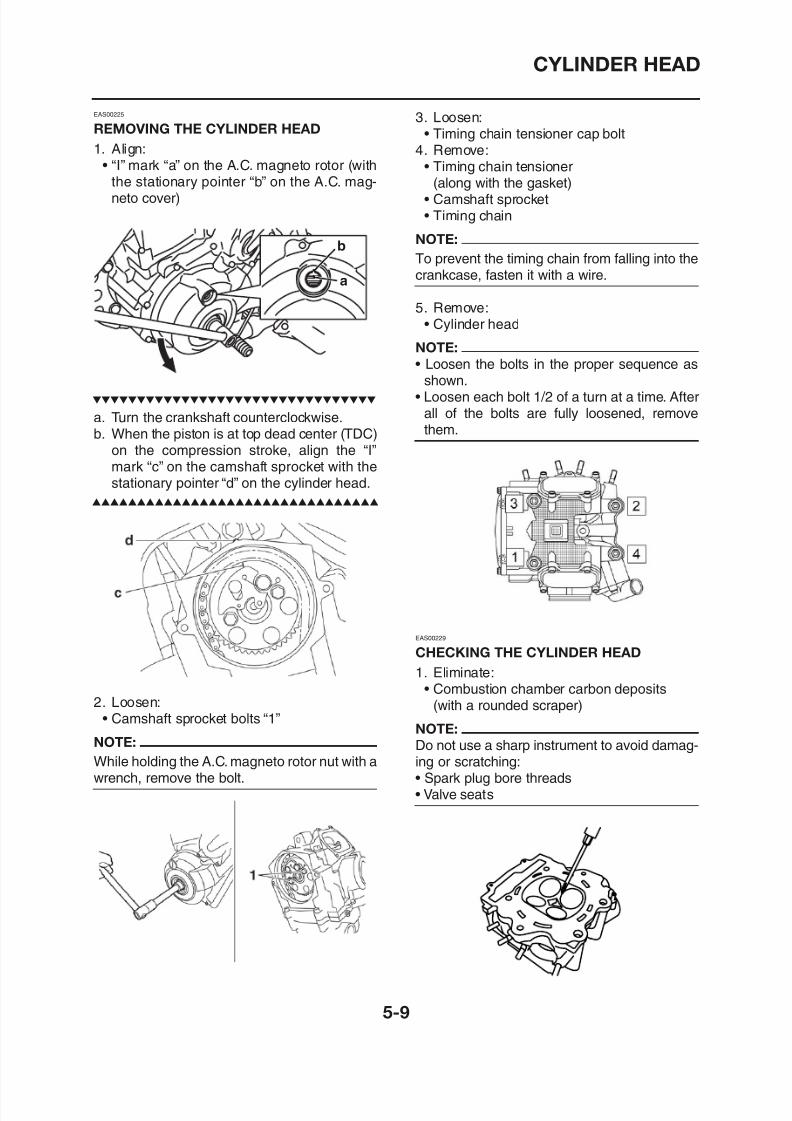
8/12/2019 Yamaha Tenere XT660Z Service Manual
http://slidepdf.com/reader/full/yamaha-tenere-xt660z-service-manual 203/398
1. Align:
• “I” mark “a” on the A.C. magneto rotor (withthe stationary pointer “b” on the A.C. mag-neto cover)
b
a
a. Turn the crankshaft counterclockwise.b. When the piston is at top dead center (TDC)
on the compression stroke, align the “I”mark “c” on the camshaft sprocket with thestationary pointer “d” on the cylinder head.
4. Remove:
• Timing chain tensioner(along with the gasket)• Camshaft sprocket• Timing chain
NOTE:
To prevent the timing chain from falling into thecrankcase, fasten it with a wire.
5. Remove:• Cylinder head
NOTE:
• Loosen the bolts in the proper sequence asshown.
• Loosen each bolt 1/2 of a turn at a time. Afterall of the bolts are fully loosened, removethem.
CYLINDER HEAD
2. Check:• Cylinder head
Damage/scratches→ Replace
EAS00212
CHECKING THE TAPPET COVERS AND
CAMSHAFT SPROCKET COVER
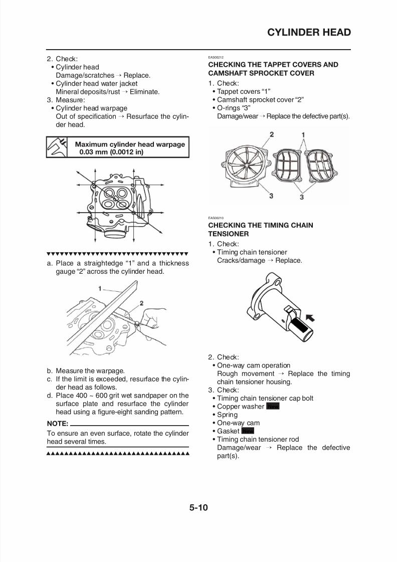
8/12/2019 Yamaha Tenere XT660Z Service Manual
http://slidepdf.com/reader/full/yamaha-tenere-xt660z-service-manual 204/398
Damage/scratches→ Replace.
• Cylinder head water jacketMineral deposits/rust → Eliminate.3. Measure:
• Cylinder head warpageOut of specification → Resurface the cylin-der head.
Maximum cylinder head warpage0.03 mm (0.0012 in)
a. Place a straightedge “1” and a thicknessgauge “2” across the cylinder head.
1. Check:• Tappet covers “1”• Camshaft sprocket cover “2”• O-rings “3”
Damage/wear→Replace the defective part(s).
EAS00210
CHECKING THE TIMING CHAINTENSIONER
1. Check:• Timing chain tensioner
Cracks/damage → Replace.
CYLINDER HEAD
CHECKING THE CAMSHAFT SPROCKET
1. Check:• Camshaft sprocket
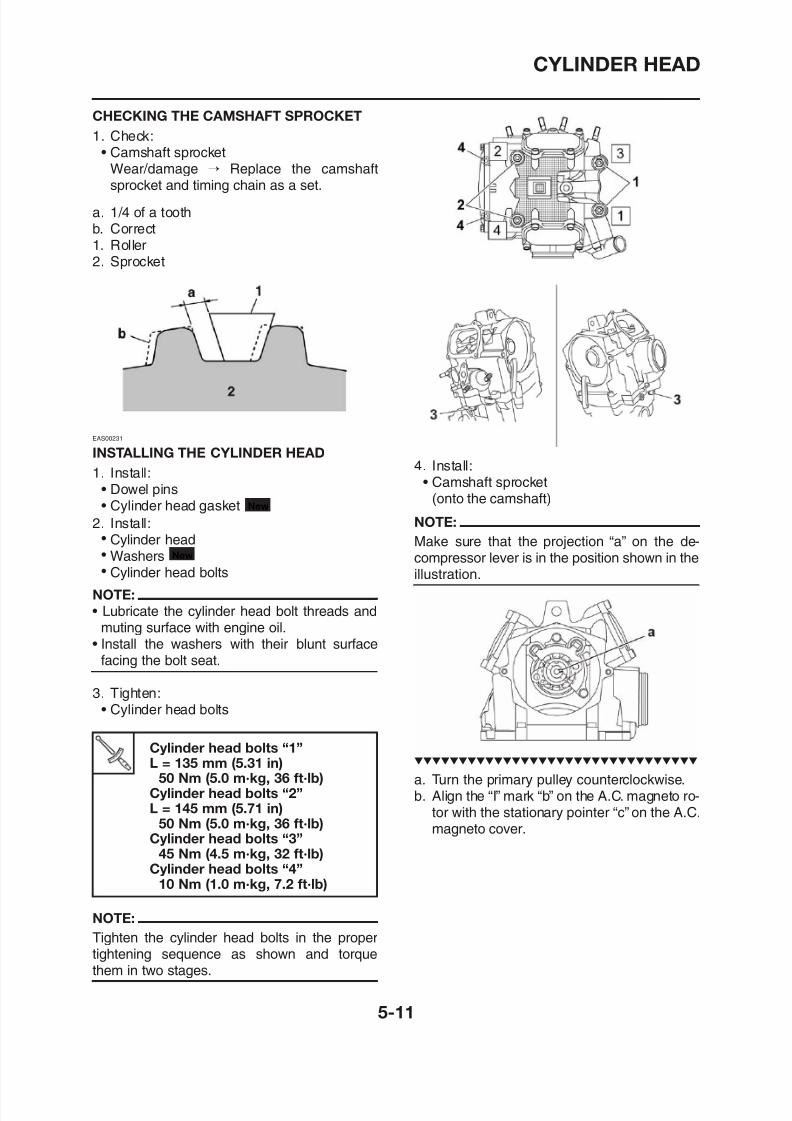
8/12/2019 Yamaha Tenere XT660Z Service Manual
http://slidepdf.com/reader/full/yamaha-tenere-xt660z-service-manual 205/398
• Camshaft sprocket
Wear/damage → Replace the camshaftsprocket and timing chain as a set.
a. 1/4 of a toothb. Correct1. Roller2. Sprocket
EAS00231
INSTALLING THE CYLINDER HEAD
1. Install:• Dowel pins• Cylinder head gasket
2. Install:• Cylinder head• Washers• Cylinder head bolts
NOTE:
New
New
4. Install:• Camshaft sprocket
(onto the camshaft)
NOTE:
Make sure that the projection “a” on the de-compressor lever is in the position shown in theillustration.
CYLINDER HEAD
a. Remove the timing chain tensioner cap bolt“1”, copper washer “2” and spring “3”.
b Release the timing chain tensioner one-way
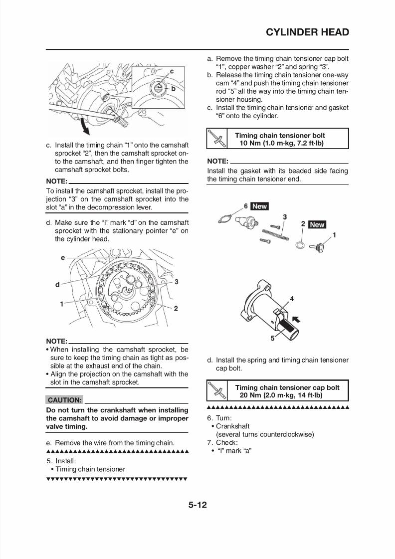
8/12/2019 Yamaha Tenere XT660Z Service Manual
http://slidepdf.com/reader/full/yamaha-tenere-xt660z-service-manual 206/398
c. Install the timing chain “1” onto the camshaft
sprocket “2”, then the camshaft sprocket on-to the camshaft, and then finger tighten thecamshaft sprocket bolts.
NOTE:
To install the camshaft sprocket, install the pro- jection “3” on the camshaft sprocket into theslot “a” in the decompression lever.
d. Make sure the “I” mark “d” on the camshaftsprocket with the stationary pointer “e” onthe cylinder head.
Timing chain tensioner bolt10 Nm (1.0 m·kg, 7.2 ft·lb)
b. Release the timing chain tensioner one way
cam “4” and push the timing chain tensionerrod “5” all the way into the timing chain ten-sioner housing.
c. Install the timing chain tensioner and gasket“6” onto the cylinder.
NOTE:
Install the gasket with its beaded side facingthe timing chain tensioner end.
4
CYLINDER HEAD
NOTE:
Check that the “I” mark “a” on the A.C. magne-to rotor is aligned with the stationary pointer “b”
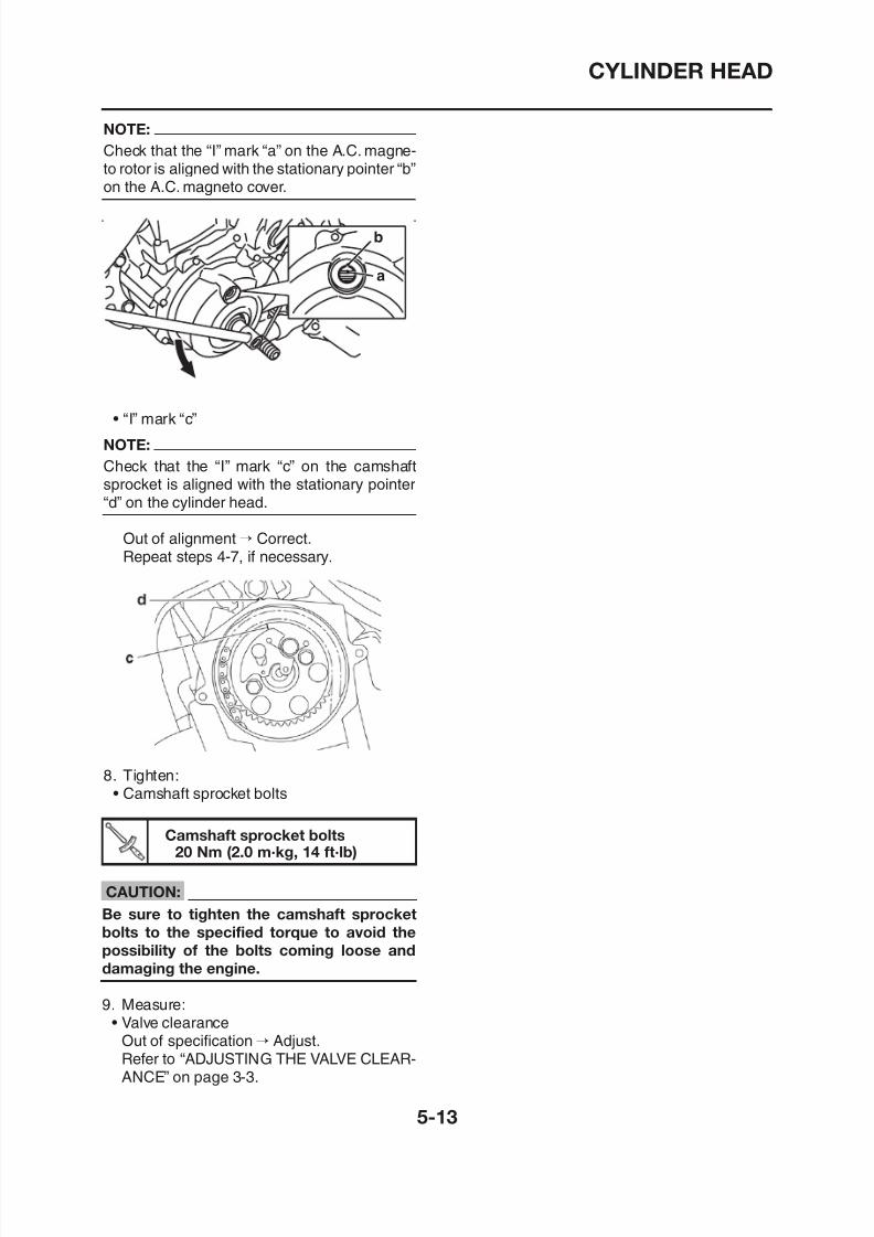
8/12/2019 Yamaha Tenere XT660Z Service Manual
http://slidepdf.com/reader/full/yamaha-tenere-xt660z-service-manual 207/398
to rotor is aligned with the stationary pointer b
on the A.C. magneto cover.
• “I” mark “c”
NOTE:
Check that the “I” mark “c” on the camshaftsprocket is aligned with the stationary pointer“d” on the cylinder head.
Out of alignment→ Correct.Repeat steps 4-7, if necessary.
b
a
ROCKER ARMS AND CAMSHAFT
Removing the rocker arms and camshaft
ROCKER ARMS AND CAMSHAFT
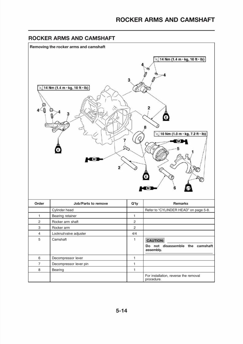
8/12/2019 Yamaha Tenere XT660Z Service Manual
http://slidepdf.com/reader/full/yamaha-tenere-xt660z-service-manual 208/398
Removing the rocker arms and camshaft
ROCKER ARMS AND CAMSHAFT
EAS00202
REMOVING THE ROCKER ARMS AND
CAMSHAFT
EAS00205
CHECKING THE CAMSHAFT
1. Check:
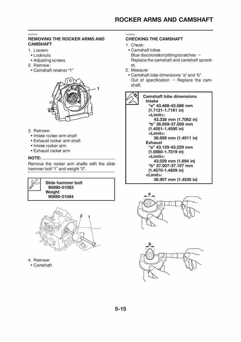
8/12/2019 Yamaha Tenere XT660Z Service Manual
http://slidepdf.com/reader/full/yamaha-tenere-xt660z-service-manual 209/398
1. Loosen:• Locknuts• Adjusting screws
2. Remove:• Camshaft retainer “1”
3. Remove:
• Intake rocker arm shaft• Exhaust rocker arm shaft• Intake rocker arm• Exhaust rocker arm
NOTE:
Remove the rocker arm shafts with the slidehammer bolt “1” and weight “2”.
1
Slid h b l
• Camshaft lobesBlue discoloration/pitting/scratches→Replace the camshaft and camshaft sprock-et.
2. Measure:• Camshaft lobe dimensions “a” and “b”
Out of specification → Replace the cam-shaft.
Camshaft lobe dimensionsIntake
“a” 43.488-43.588 mm(1.7121-1.7161 in)<Limit>:
43.338 mm (1.7062 in)“b” 36.959-37.059 mm(1.4551-1.4590 in)<Limit>:
36.859 mm (1.4511 in)Exhaust
“a” 43.129-43.229 mm(1.6980-1.7019 in)<Limit>:
43.029 mm (1.694 in)“b” 37.007-37.107 mm(1.4570-1.4609 in)
<Limit>:
36 907 mm (1 4530 in)
ROCKER ARMS AND CAMSHAFT
3. Measure:• Camshaft runout
Out of specification→ Replace.
2. Check:• Rocker arm shaft
Blue discoloration/excessive wear/pitting/
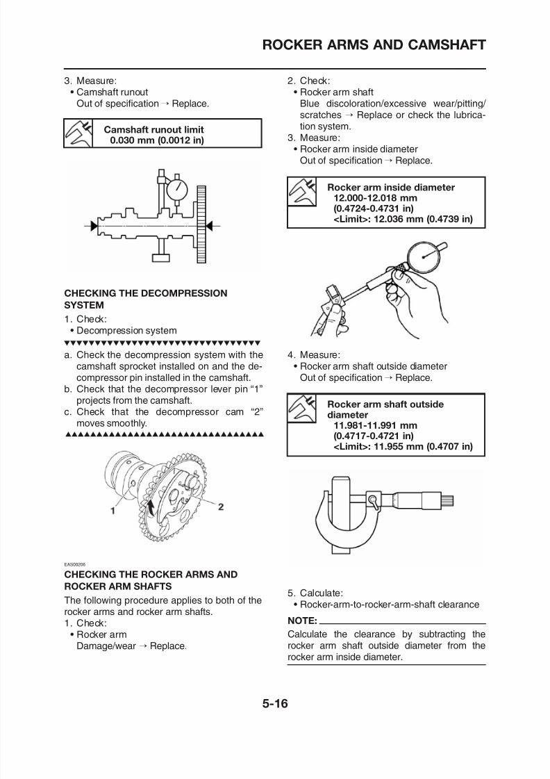
8/12/2019 Yamaha Tenere XT660Z Service Manual
http://slidepdf.com/reader/full/yamaha-tenere-xt660z-service-manual 210/398
p p
Camshaft runout limit0.030 mm (0.0012 in)
CHECKING THE DECOMPRESSION
SYSTEM
1. Check:• Decompression system
a. Check the decompression system with thecamshaft sprocket installed on and the de-compressor pin installed in the camshaft.
b. Check that the decompressor lever pin “1”projects from the camshaft.
c Check that the decompressor cam “2”
p gscratches → Replace or check the lubrica-tion system.
3. Measure:• Rocker arm inside diameter
Out of specification→ Replace.
Rocker arm inside diameter12.000-12.018 mm(0.4724-0.4731 in)
<Limit>: 12.036 mm (0.4739 in)
Rocker arm shaft outsidediameter
4. Measure:• Rocker arm shaft outside diameter
Out of specification→ Replace.
ROCKER ARMS AND CAMSHAFT
Above 0.081 mm (0.0032 in) → Replace thedefective part(s). 1
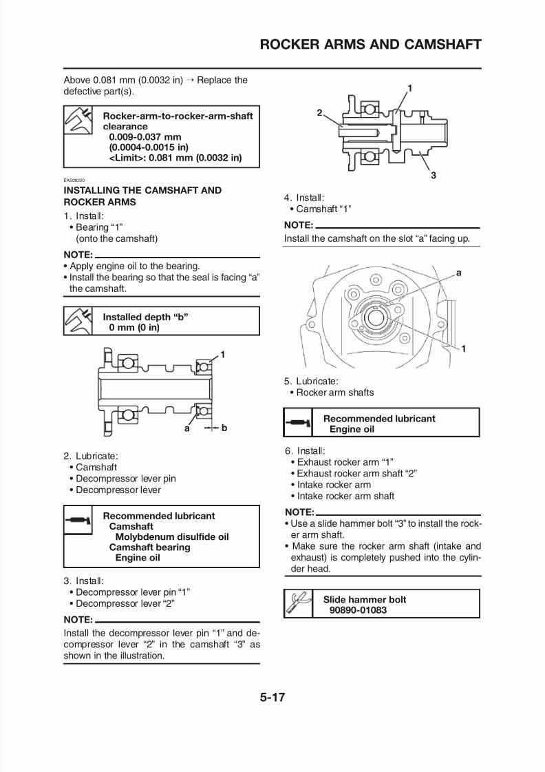
8/12/2019 Yamaha Tenere XT660Z Service Manual
http://slidepdf.com/reader/full/yamaha-tenere-xt660z-service-manual 211/398
Rocker-arm-to-rocker-arm-shaftclearance0.009-0.037 mm(0.0004-0.0015 in)<Limit>: 0.081 mm (0.0032 in)
EAS00220
INSTALLING THE CAMSHAFT AND
ROCKER ARMS
1. Install:• Bearing “1”
(onto the camshaft)
NOTE:
• Apply engine oil to the bearing.• Install the bearing so that the seal is facing “a”
the camshaft.
Installed depth “b”0 mm (0 in)
1
4. Install:• Camshaft “1”
NOTE:
Install the camshaft on the slot “a” facing up.
5. Lubricate:• Rocker arm shafts
1
a
2
3
ROCKER ARMS AND CAMSHAFT
1
2
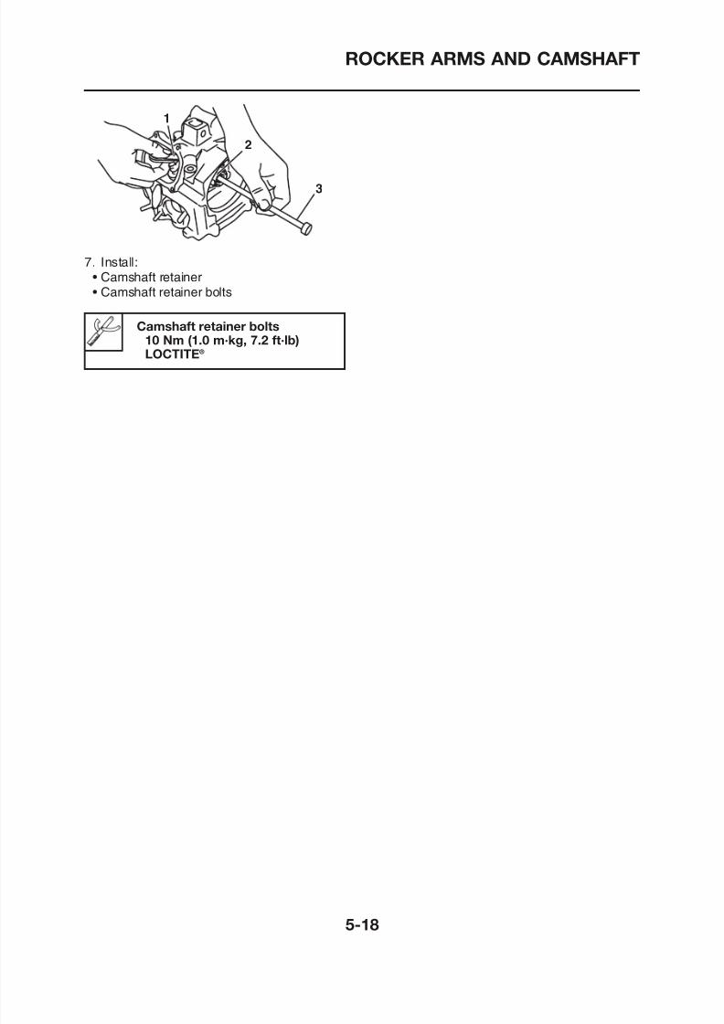
8/12/2019 Yamaha Tenere XT660Z Service Manual
http://slidepdf.com/reader/full/yamaha-tenere-xt660z-service-manual 212/398
7. Install:• Camshaft retainer• Camshaft retainer bolts
2
3
Camshaft retainer bolts10 Nm (1.0 m·kg, 7.2 ft·lb)LOCTITE®
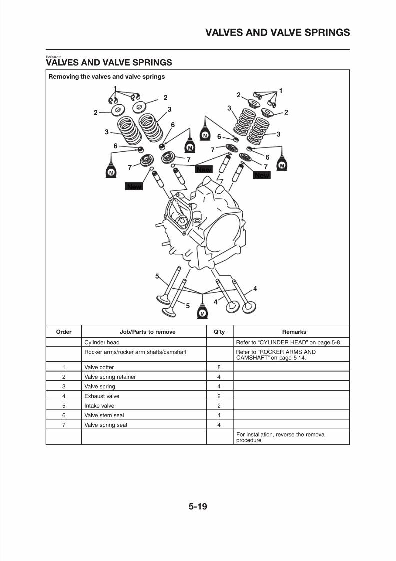
8/12/2019 Yamaha Tenere XT660Z Service Manual
http://slidepdf.com/reader/full/yamaha-tenere-xt660z-service-manual 213/398
VALVES AND VALVE SPRINGS
EAS00237
REMOVING THE VALVES
The following procedure applies to all of the
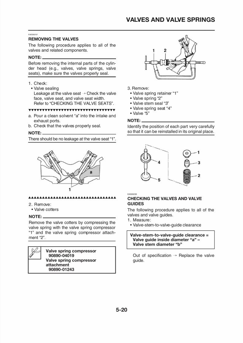
8/12/2019 Yamaha Tenere XT660Z Service Manual
http://slidepdf.com/reader/full/yamaha-tenere-xt660z-service-manual 214/398
valves and related components.
NOTE:
Before removing the internal parts of the cylin-der head (e.g., valves, valve springs, valveseats), make sure the valves properly seal.
1. Check:• Valve sealing
Leakage at the valve seat→
Check the valveface, valve seat, and valve seat width.Refer to “CHECKING THE VALVE SEATS”.
a. Pour a clean solvent “a” into the intake andexhaust ports.
b. Check that the valves properly seal.
NOTE:
There should be no leakage at the valve seat “1”.
3. Remove:• Valve spring retainer “1”• Valve spring “2”• Valve stem seal “3”• Valve spring seat “4”• Valve “5”
NOTE:
Identify the position of each part very carefullyso that it can be reinstalled in its original place.
VALVES AND VALVE SPRINGS
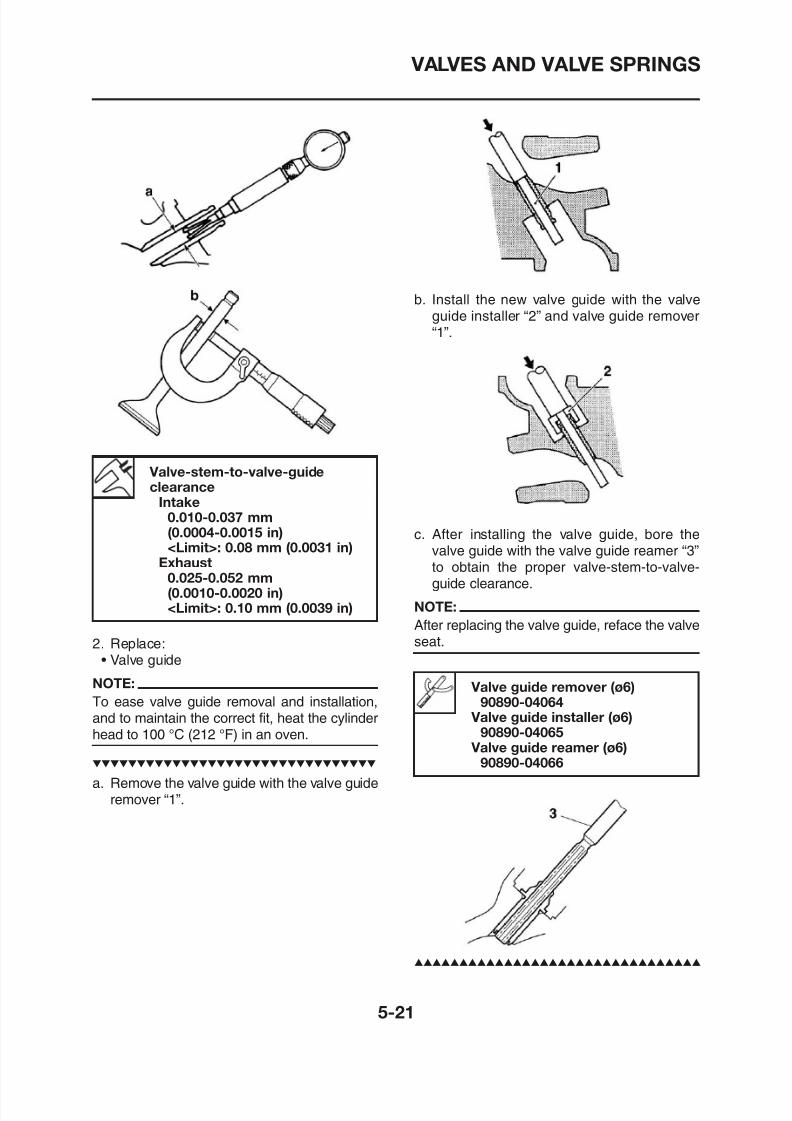
8/12/2019 Yamaha Tenere XT660Z Service Manual
http://slidepdf.com/reader/full/yamaha-tenere-xt660z-service-manual 215/398
Valve-stem-to-valve-guideclearance
Intake0.010-0.037 mm(0.0004-0.0015 in)<Limit>: 0.08 mm (0.0031 in)
Exhaust0.025-0.052 mm
(0 0010 0 0020 in)
b. Install the new valve guide with the valve
guide installer “2” and valve guide remover“1”.
c. After installing the valve guide, bore thevalve guide with the valve guide reamer “3”to obtain the proper valve-stem-to-valve-
guide clearance
VALVES AND VALVE SPRINGS
3. Eliminate:• Carbon deposits
(from the valve face and valve seat)
EAS00240
CHECKING THE VALVE SEATS
The following procedure applies to all of thel d l t
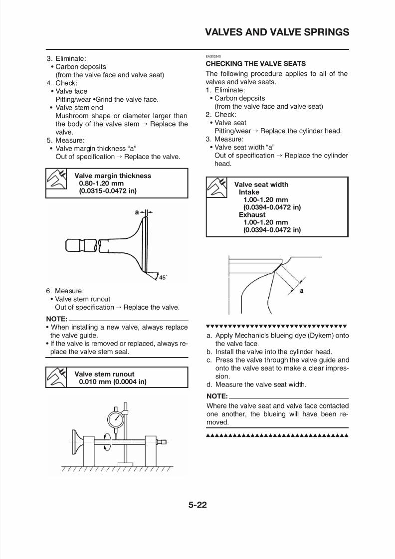
8/12/2019 Yamaha Tenere XT660Z Service Manual
http://slidepdf.com/reader/full/yamaha-tenere-xt660z-service-manual 216/398
4. Check:• Valve face
Pitting/wear •Grind the valve face.• Valve stem end
Mushroom shape or diameter larger thanthe body of the valve stem → Replace thevalve.
5. Measure:• Valve margin thickness “a”
Out of specification→ Replace the valve.
Valve margin thickness0.80-1.20 mm(0.0315-0.0472 in)
6 Measure:V l
valves and valve seats.1. Eliminate:
• Carbon deposits(from the valve face and valve seat)
2. Check:• Valve seat
Pitting/wear→ Replace the cylinder head.3. Measure:
• Valve seat width “a”
Out of specification → Replace the cylinderhead.
Valve seat widthIntake
1.00-1.20 mm(0.0394-0.0472 in)
Exhaust
1.00-1.20 mm(0.0394-0.0472 in)
VALVES AND VALVE SPRINGS
4. Lap:• Valve face• Valve seat
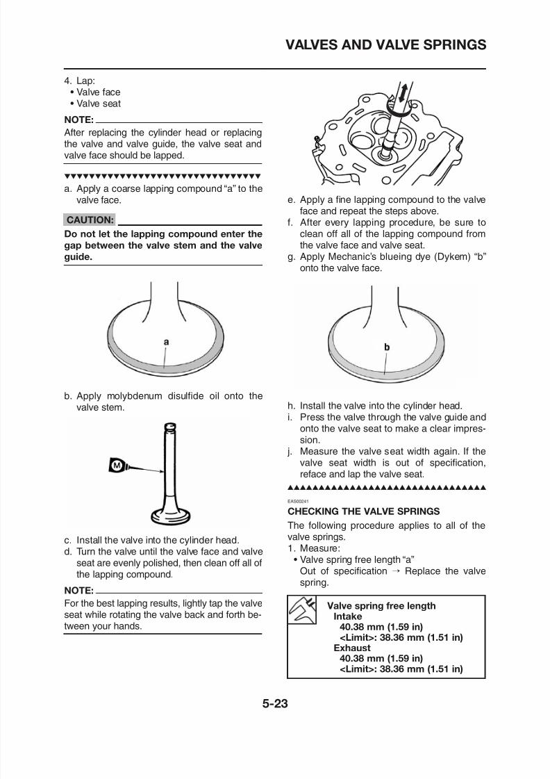
8/12/2019 Yamaha Tenere XT660Z Service Manual
http://slidepdf.com/reader/full/yamaha-tenere-xt660z-service-manual 217/398
NOTE:After replacing the cylinder head or replacingthe valve and valve guide, the valve seat andvalve face should be lapped.
a. Apply a coarse lapping compound “a” to thevalve face.
CAUTION:
Do not let the lapping compound enter the
gap between the valve stem and the valve
guide.
b. Apply molybdenum disulfide oil onto the
valve stem
e. Apply a fine lapping compound to the valveface and repeat the steps above.
f. After every lapping procedure, be sure toclean off all of the lapping compound fromthe valve face and valve seat.
g. Apply Mechanic’s blueing dye (Dykem) “b”onto the valve face.
h Install the valve into the cylinder head
VALVES AND VALVE SPRINGS
EAS00245
INSTALLING THE VALVES
The following procedure applies to all of theal es and related components
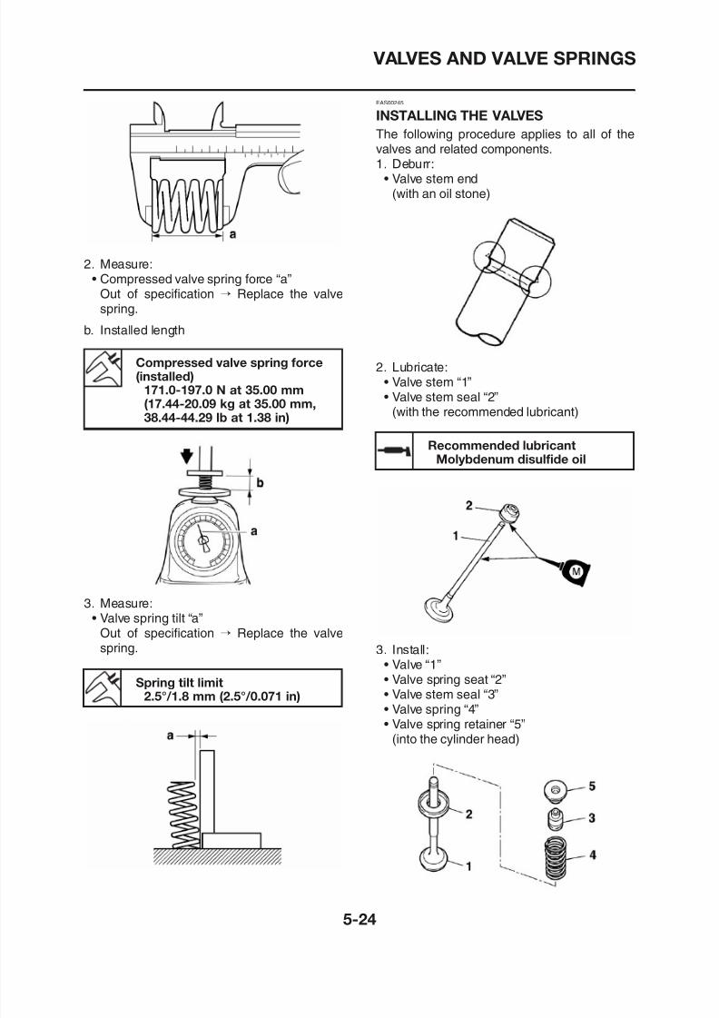
8/12/2019 Yamaha Tenere XT660Z Service Manual
http://slidepdf.com/reader/full/yamaha-tenere-xt660z-service-manual 218/398
2. Measure:
• Compressed valve spring force “a”Out of specification → Replace the valvespring.
b. Installed length
Compressed valve spring force(installed)
171.0-197.0 N at 35.00 mm
(17.44-20.09 kg at 35.00 mm,38.44-44.29 lb at 1.38 in)
valves and related components.
1. Deburr:• Valve stem end
(with an oil stone)
2. Lubricate:• Valve stem “1”• Valve stem seal “2”
(with the recommended lubricant)
Recommended lubricantMolybdenum disulfide oil
VALVES AND VALVE SPRINGS
NOTE:
• Install the valve spring with the larger pitch “a”facing up.I t ll th l i ith it i t d d
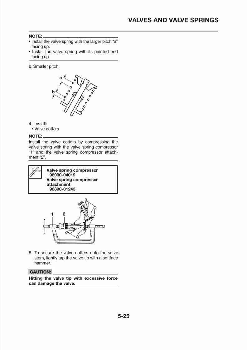
8/12/2019 Yamaha Tenere XT660Z Service Manual
http://slidepdf.com/reader/full/yamaha-tenere-xt660z-service-manual 219/398
• Install the valve spring with its painted endfacing up.
b. Smaller pitch
4. Install:• Valve cotters
NOTE:
Install the valve cotters by compressing thevalve spring with the valve spring compressor“1” and the valve spring compressor attach-ment “2”.
Valve spring compressor98090-04019
Valve spring compressor
attachment
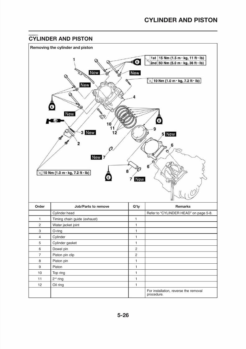
8/12/2019 Yamaha Tenere XT660Z Service Manual
http://slidepdf.com/reader/full/yamaha-tenere-xt660z-service-manual 220/398
CYLINDER AND PISTON
EAS00253
REMOVING THE CYLINDER ANDPISTON
1 Remove:
NOTE:
When removing a piston ring, open the endgap with your fingers and lift the other side ofth i th i t
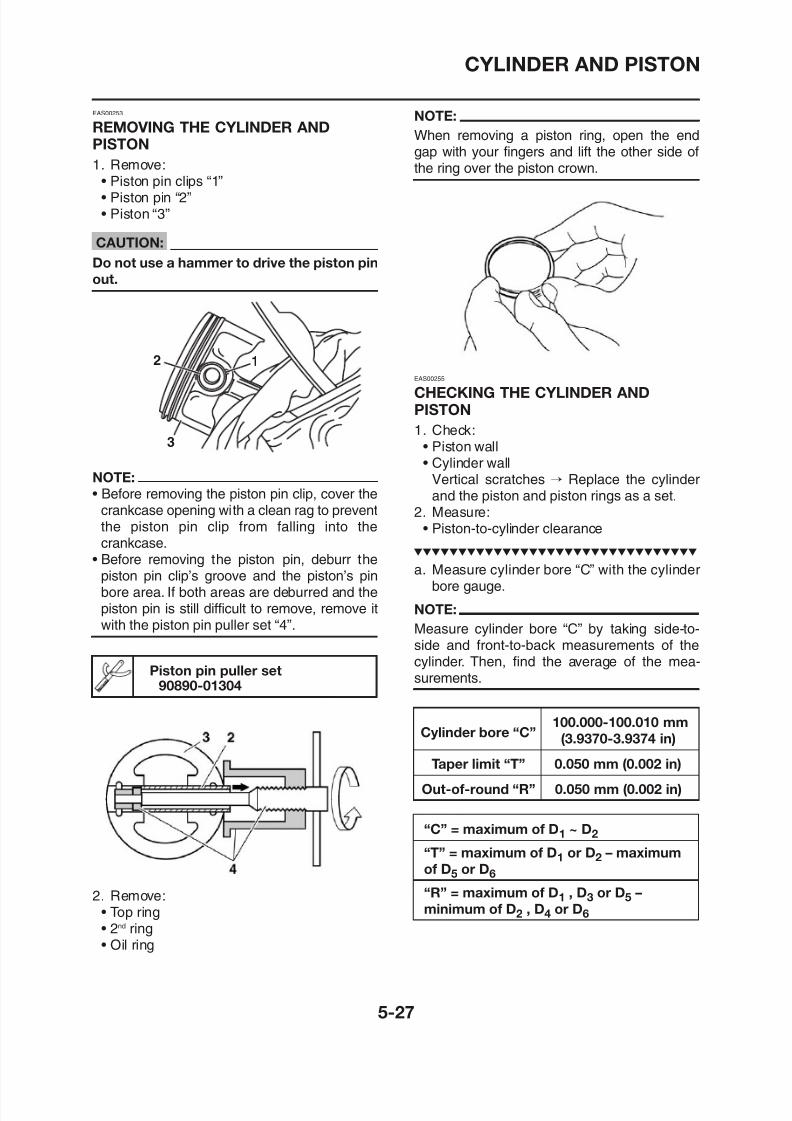
8/12/2019 Yamaha Tenere XT660Z Service Manual
http://slidepdf.com/reader/full/yamaha-tenere-xt660z-service-manual 221/398
1. Remove:• Piston pin clips “1”• Piston pin “2”• Piston “3”
CAUTION:
Do not use a hammer to drive the piston pin
out.
NOTE:
• Before removing the piston pin clip, cover thecrankcase opening with a clean rag to preventthe piston pin clip from falling into thecrankcase.
• Before removing the piston pin, deburr thepiston pin clip’s groove and the piston’s pin
bore area If both areas are deburred and the
3
2 1
the ring over the piston crown.
EAS00255
CHECKING THE CYLINDER ANDPISTON
1. Check:
• Piston wall• Cylinder wallVertical scratches → Replace the cylinderand the piston and piston rings as a set.
2. Measure:• Piston-to-cylinder clearance
a. Measure cylinder bore “C” with the cylinder
bore gauge
CYLINDER AND PISTON
EAS00263
CHECKING THE PISTON RINGS
1. Measure:• Piston ring side clearance
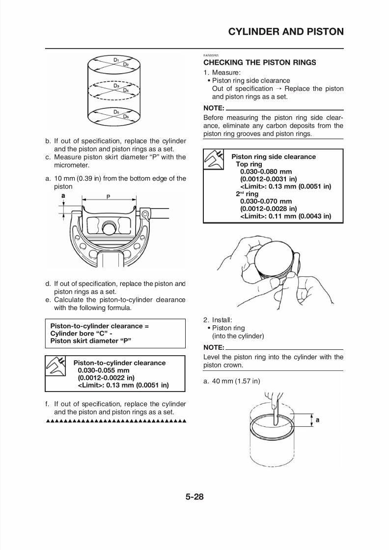
8/12/2019 Yamaha Tenere XT660Z Service Manual
http://slidepdf.com/reader/full/yamaha-tenere-xt660z-service-manual 222/398
b. If out of specification, replace the cylinderand the piston and piston rings as a set.
c. Measure piston skirt diameter “P” with themicrometer.
a. 10 mm (0.39 in) from the bottom edge of thepiston
d. If out of specification, replace the piston and
piston rings as a set
• Piston ring side clearance
Out of specification → Replace the pistonand piston rings as a set.
NOTE:
Before measuring the piston ring side clear-ance, eliminate any carbon deposits from thepiston ring grooves and piston rings.
Piston ring side clearanceTop ring
0.030-0.080 mm(0.0012-0.0031 in)<Limit>: 0.13 mm (0.0051 in)
2nd ring0.030-0.070 mm(0.0012-0.0028 in)<Limit>: 0.11 mm (0.0043 in)
CYLINDER AND PISTON
3. Measure:• Piston ring end gap
Out of specification→Replace the piston ring.
Piston pin bore inside diameter23.004-23.015 mm(0.9057-0.9061 in)
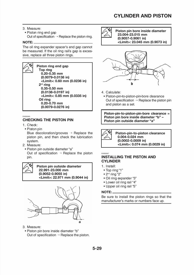
8/12/2019 Yamaha Tenere XT660Z Service Manual
http://slidepdf.com/reader/full/yamaha-tenere-xt660z-service-manual 223/398
NOTE:The oil ring expander spacer’s end gap cannotbe measured. If the oil ring rail’s gap is exces-sive, replace all three piston rings.
Piston ring end gapTop ring
0.20-0.35 mm
(0.0079-0.0138 in)<Limit>: 0.60 mm (0.0236 in)
2nd ring0.35-0.50 mm(0.0138-0.0197 in)<Limit>: 0.85 mm (0.0335 in)
Oil ring0.20-0.70 mm(0.0079-0.0276 in)
EAS00265
CHECKING THE PISTON PIN
1. Check:• Piston pin
Blue discoloration/grooves → Replace thepiston pin, and then check the lubricationsystem.
2 Measure:
<Limit>: 23.045 mm (0.9073 in)
4. Calculate:• Piston-pin-to-piston-pin-bore clearance
Out of specification → Replace the piston pinand piston as a set.
Piston-pin-to-piston clearance0.004-0.024 mm(0.0002-0.0009 in)
<Limit>: 0 074 mm (0 0029 in)
Piston-pin-to-piston-pin-bore clearance =Piston pin bore inside diameter “b” –Piston pin outside diameter “a”
CYLINDER AND PISTON
5. Offset:• piston ring end gaps
a. Top ring
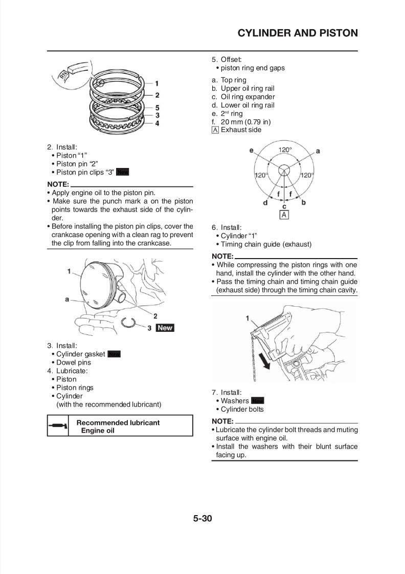
8/12/2019 Yamaha Tenere XT660Z Service Manual
http://slidepdf.com/reader/full/yamaha-tenere-xt660z-service-manual 224/398
2. Install:• Piston “1”• Piston pin “2”• Piston pin clips “3”
NOTE:
• Apply engine oil to the piston pin.• Make sure the punch mark a on the piston
points towards the exhaust side of the cylin-der.
• Before installing the piston pin clips, cover thecrankcase opening with a clean rag to preventthe clip from falling into the crankcase.
New
b. Upper oil ring railc. Oil ring expanderd. Lower oil ring raile. 2nd ringf. 20 mm (0.79 in) å Exhaust side
6. Install:• Cylinder “1”• Timing chain guide (exhaust)
NOTE:
• While compressing the piston rings with onehand, install the cylinder with the other hand.
• Pass the timing chain and timing chain guide(exhaust side) through the timing chain cavity.
CYLINDER AND PISTON
8. Tighten:• Cylinder bolts
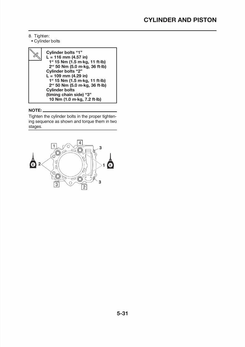
8/12/2019 Yamaha Tenere XT660Z Service Manual
http://slidepdf.com/reader/full/yamaha-tenere-xt660z-service-manual 225/398
Cylinder bolts “1”L = 116 mm (4.57 in)1st 15 Nm (1.5 m·kg, 11 ft·lb)2nd 50 Nm (5.0 m·kg, 36 ft·lb)
Cylinder bolts “2”L = 109 mm (4.29 in)
1st 15 Nm (1.5 m·kg, 11 ft·lb)2nd 50 Nm (5.0 m·kg, 36 ft·lb)
Cylinder bolts(timing chain side) “3”
10 Nm (1.0 m·kg, 7.2 ft·lb)
NOTE:
Tighten the cylinder bolts in the proper tighten-ing sequence as shown and torque them in twostages.
CLUTCH
Removing the clutch cover
EAS00273
CLUTCH
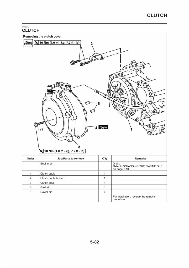
8/12/2019 Yamaha Tenere XT660Z Service Manual
http://slidepdf.com/reader/full/yamaha-tenere-xt660z-service-manual 226/398
CLUTCH
Removing the pull lever shaft
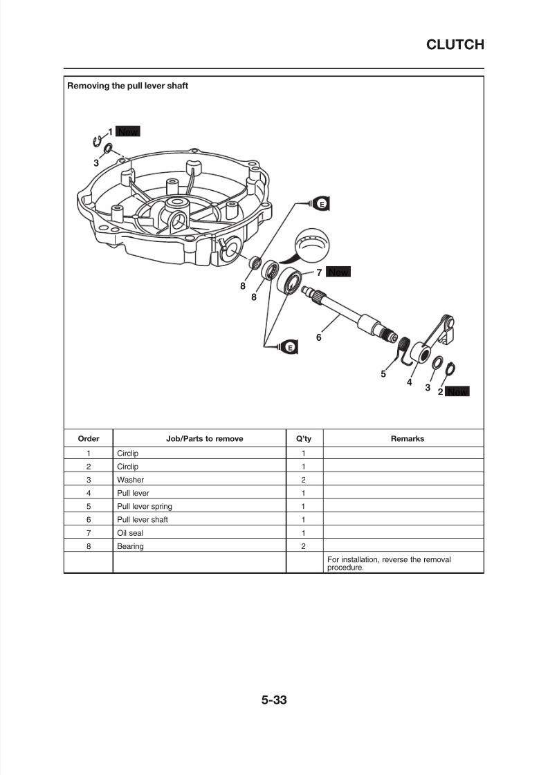
8/12/2019 Yamaha Tenere XT660Z Service Manual
http://slidepdf.com/reader/full/yamaha-tenere-xt660z-service-manual 227/398
New
New
New
E
23
45
7
8
8
6
3
1
E
CLUTCH
Removing the clutch
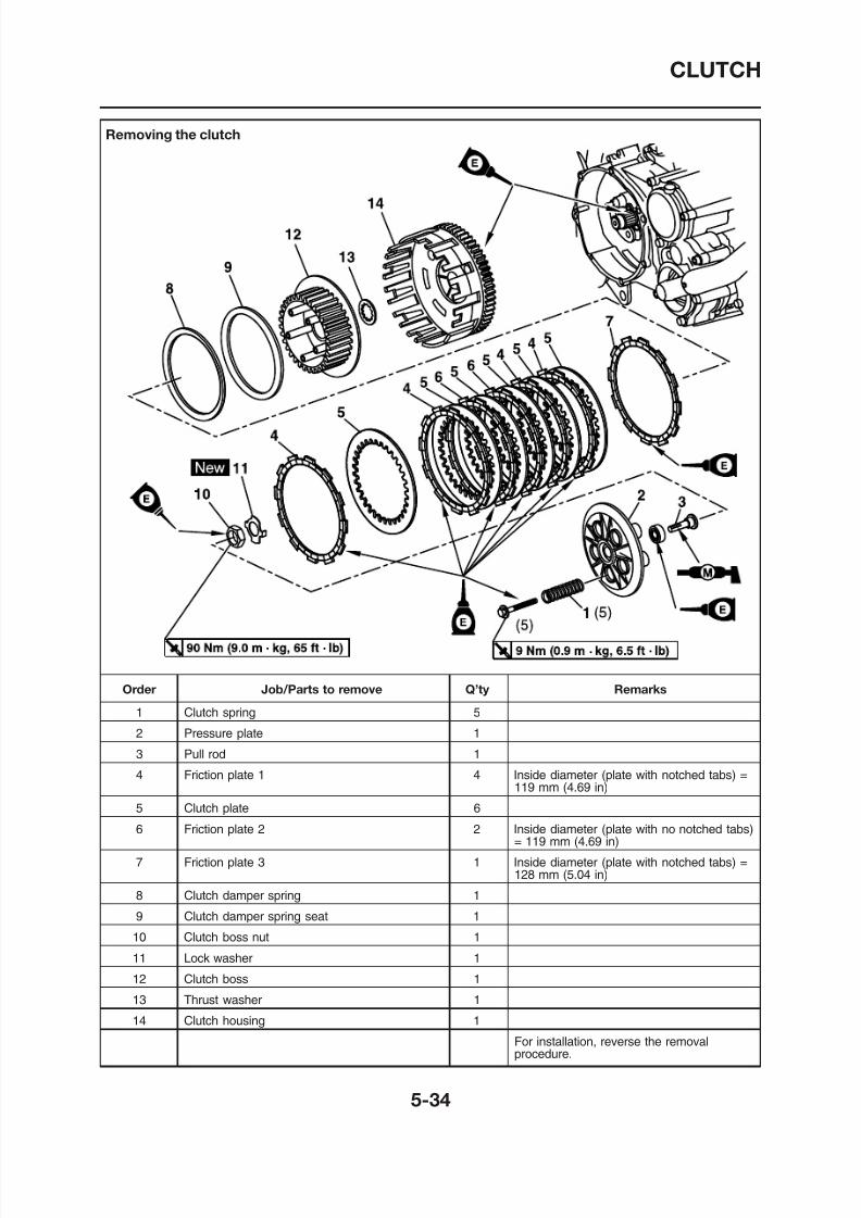
8/12/2019 Yamaha Tenere XT660Z Service Manual
http://slidepdf.com/reader/full/yamaha-tenere-xt660z-service-manual 228/398
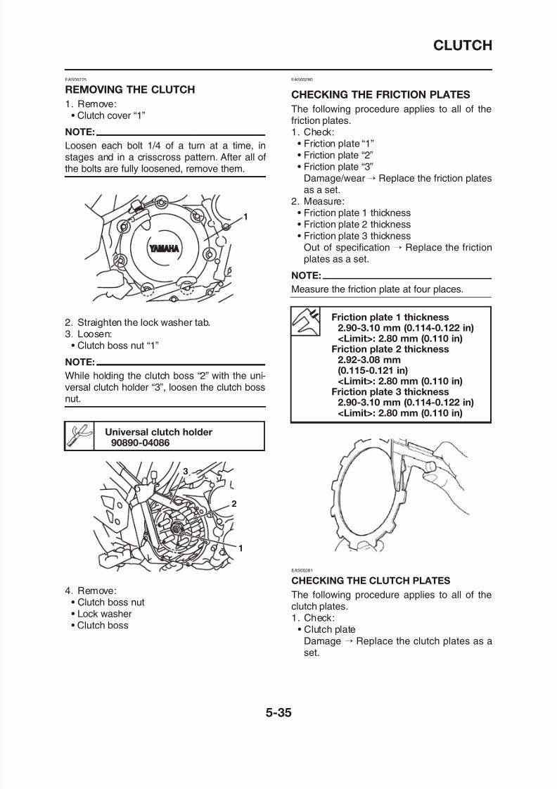
8/12/2019 Yamaha Tenere XT660Z Service Manual
http://slidepdf.com/reader/full/yamaha-tenere-xt660z-service-manual 229/398
CLUTCH
2. Measure:• Clutch plate warpage
(with a surface plate and thickness gauge“1”)
EAS00284
CHECKING THE CLUTCH HOUSING
1. Check:• Clutch housing dogs
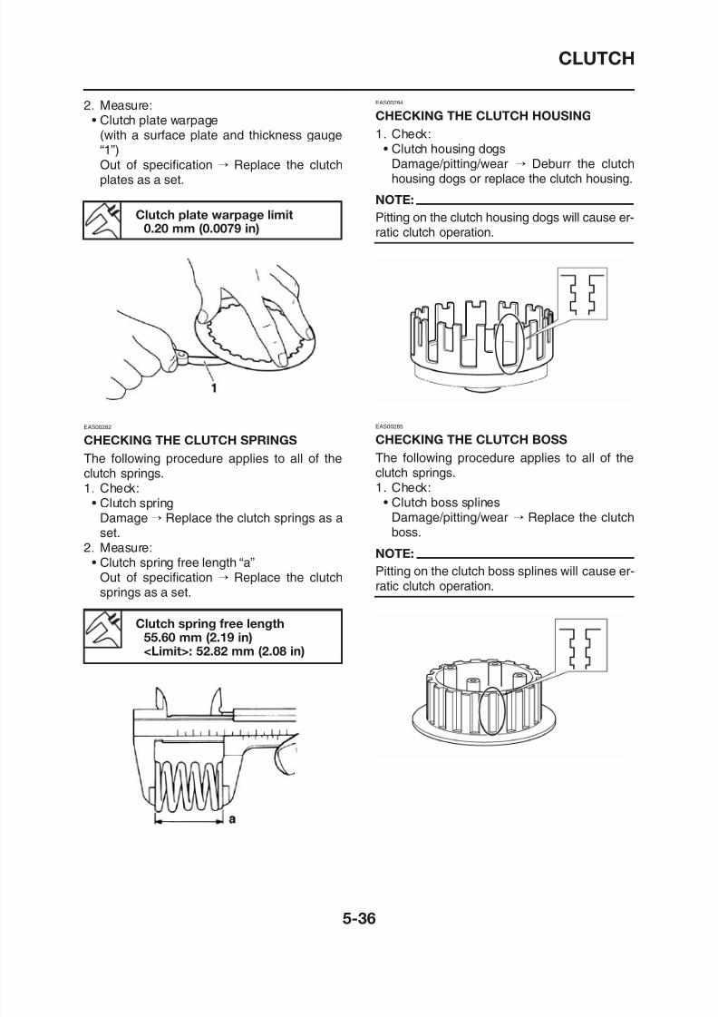
8/12/2019 Yamaha Tenere XT660Z Service Manual
http://slidepdf.com/reader/full/yamaha-tenere-xt660z-service-manual 230/398
)
Out of specification → Replace the clutchplates as a set.
Clutch plate warpage limit0.20 mm (0.0079 in)
EAS00282
CHECKING THE CLUTCH SPRINGS
The following procedure applies to all of theclutch springs.1. Check:
• Clutch springDamage → Replace the clutch springs as a
t
g g
Damage/pitting/wear → Deburr the clutchhousing dogs or replace the clutch housing.
NOTE:
Pitting on the clutch housing dogs will cause er-ratic clutch operation.
EAS00285
CHECKING THE CLUTCH BOSS
The following procedure applies to all of theclutch springs.1. Check:
• Clutch boss splinesDamage/pitting/wear → Replace the clutch
b
CLUTCH
EAS00286
CHECKING THE PRESSURE PLATE
1. Check:• Pressure plate “1”
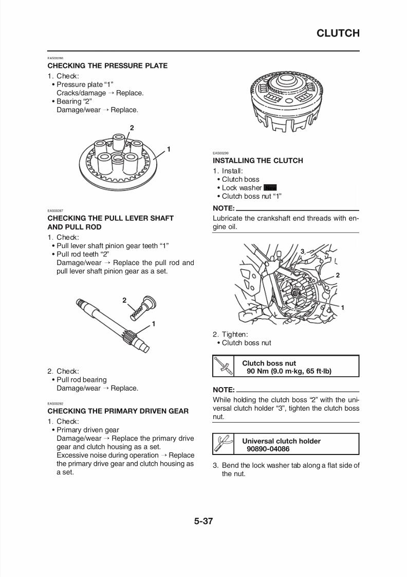
8/12/2019 Yamaha Tenere XT660Z Service Manual
http://slidepdf.com/reader/full/yamaha-tenere-xt660z-service-manual 231/398
p
Cracks/damage → Replace.• Bearing “2”
Damage/wear → Replace.
EAS00287
CHECKING THE PULL LEVER SHAFT
AND PULL ROD
1. Check:• Pull lever shaft pinion gear teeth “1”• Pull rod teeth “2”
Damage/wear → Replace the pull rod andpull lever shaft pinion gear as a set.
2
2
1EAS00299
INSTALLING THE CLUTCH1. Install:
• Clutch boss• Lock washer• Clutch boss nut “1”
NOTE:
Lubricate the crankshaft end threads with en-gine oil.
3
2
1
New
CLUTCH
4. Lubricate:• Friction plates• Clutch plates
(with the recommended lubricant)
c a
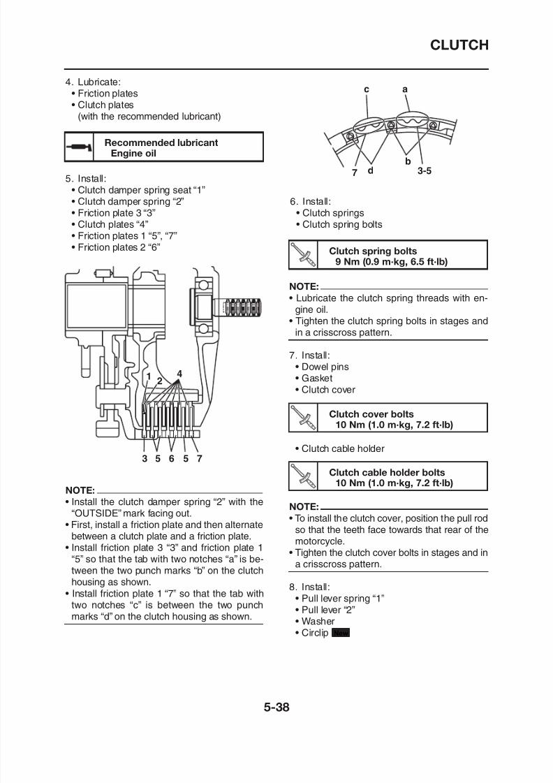
8/12/2019 Yamaha Tenere XT660Z Service Manual
http://slidepdf.com/reader/full/yamaha-tenere-xt660z-service-manual 232/398
( )
Recommended lubricantEngine oil
5. Install:• Clutch damper spring seat “1”• Clutch damper spring “2”• Friction plate 3 “3”• Clutch plates “4”• Friction plates 1 “5”, “7”• Friction plates 2 “6”
42
1
6. Install:• Clutch springs• Clutch spring bolts
3-5
bd7
Clutch spring bolts9 Nm (0.9 m·kg, 6.5 ft·lb)
NOTE:
• Lubricate the clutch spring threads with en-gine oil.
• Tighten the clutch spring bolts in stages andin a crisscross pattern.
7. Install:• Dowel pins• Gasket• Clutch cover
Cl t h b lt
CLUTCH
NOTE:
• Install the pull lever with the “UP” mark facingup.
• Align the punch mark “a” on the pull lever with
12.Adjust:• Clutch cable free play
Refer to “ADJUSTING THE CLUTCH CA-BLE FREE PLAY” on page 3-11.
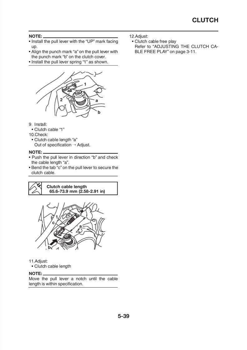
8/12/2019 Yamaha Tenere XT660Z Service Manual
http://slidepdf.com/reader/full/yamaha-tenere-xt660z-service-manual 233/398
g p p
the punch mark “b” on the clutch cover.• Install the pull lever spring “1” as shown.
9. Install:• Clutch cable “1”
10.Check:
• Clutch cable length “a”Out of specification→ Adjust.
NOTE:
• Push the pull lever in direction “b” and checkthe cable length “a”.
• Bend the tab “c” on the pull lever to secure theclutch cable.
1
a
b
2
Cl t h bl l th
p g
OIL PUMP
Removing the oil pump
OIL PUMP
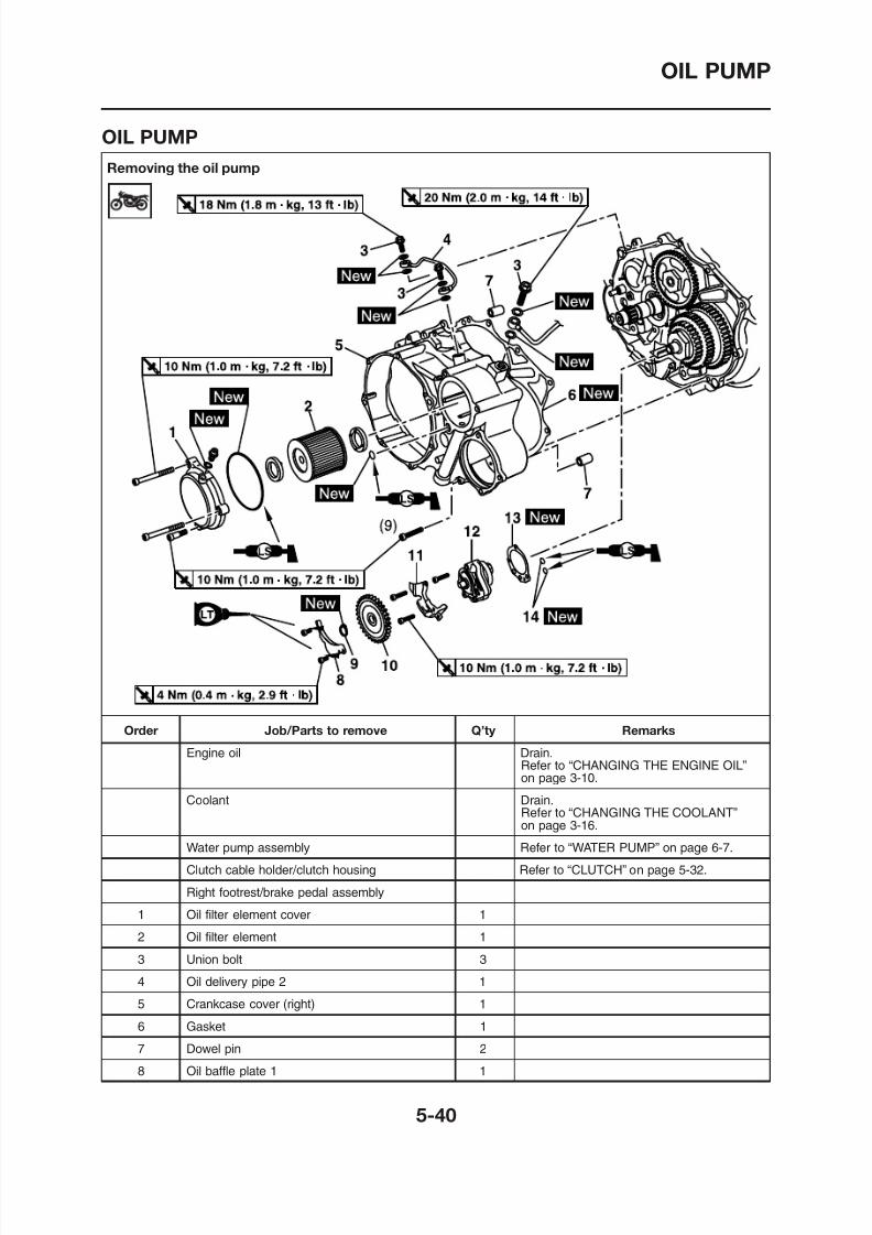
8/12/2019 Yamaha Tenere XT660Z Service Manual
http://slidepdf.com/reader/full/yamaha-tenere-xt660z-service-manual 234/398
OIL PUMP
Removing the oil pump
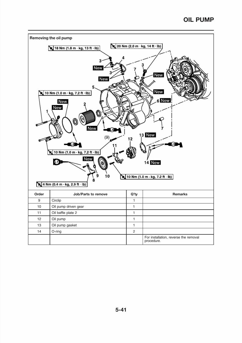
8/12/2019 Yamaha Tenere XT660Z Service Manual
http://slidepdf.com/reader/full/yamaha-tenere-xt660z-service-manual 235/398
OIL PUMP
Disassembling the oil pump
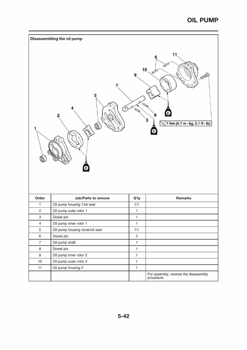
8/12/2019 Yamaha Tenere XT660Z Service Manual
http://slidepdf.com/reader/full/yamaha-tenere-xt660z-service-manual 236/398
OIL PUMP
EAS00364
CHECKING THE OIL PUMP
1. Check:• Oil pump driven gear “1”
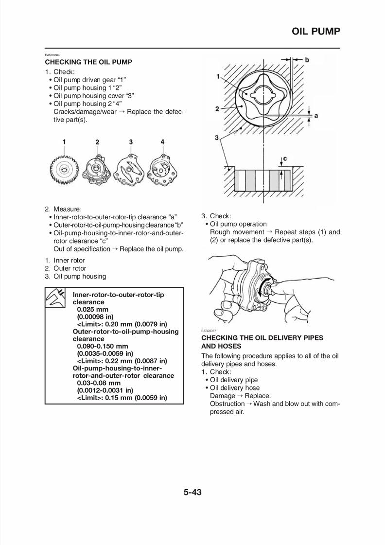
8/12/2019 Yamaha Tenere XT660Z Service Manual
http://slidepdf.com/reader/full/yamaha-tenere-xt660z-service-manual 237/398
• Oil pump housing 1 “2”• Oil pump housing cover “3”• Oil pump housing 2 “4”
Cracks/damage/wear → Replace the defec-tive part(s).
2. Measure:• Inner-rotor-to-outer-rotor-tip clearance “a”• Outer-rotor-to-oil-pump-housing clearance “b”• Oil-pump-housing-to-inner-rotor-and-outer-
rotor clearance “c”Out of specification → Replace the oil pump.
1. Inner rotor2. Outer rotor3. Oil pump housing
3. Check:• Oil pump operation
Rough movement → Repeat steps (1) and(2) or replace the defective part(s).
OIL PUMP
EAS00375
ASSEMBLING THE OIL PUMP
1. Lubricate:• Oil pump inner rotor 1
EAS00376
INSTALLING THE OIL PUMP
1. Install:• Oil pump gasket New
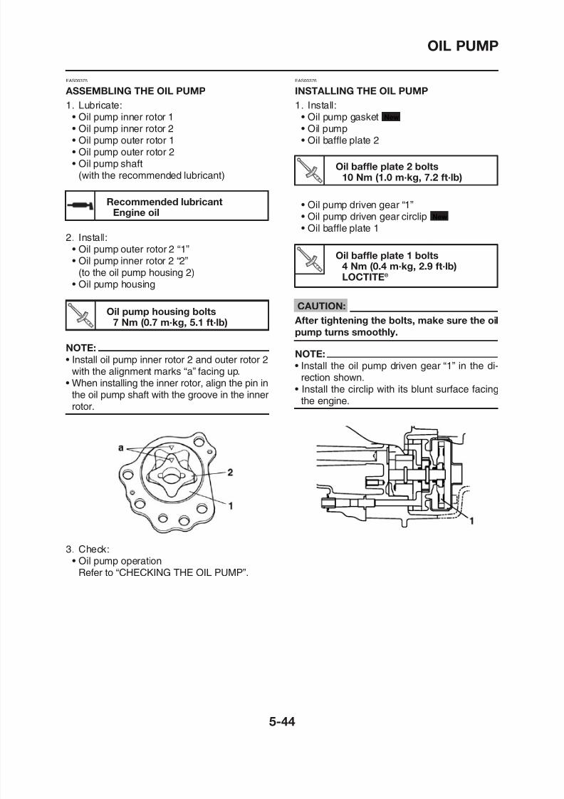
8/12/2019 Yamaha Tenere XT660Z Service Manual
http://slidepdf.com/reader/full/yamaha-tenere-xt660z-service-manual 238/398
• Oil pump inner rotor 2• Oil pump outer rotor 1• Oil pump outer rotor 2• Oil pump shaft
(with the recommended lubricant)
Recommended lubricantEngine oil
2. Install:• Oil pump outer rotor 2 “1”• Oil pump inner rotor 2 “2”
(to the oil pump housing 2)• Oil pump housing
Oil pump housing bolts
7 Nm (0.7 m·kg, 5.1 ft·lb)
NOTE:
• Install oil pump inner rotor 2 and outer rotor 2with the alignment marks “a” facing up.
• When installing the inner rotor, align the pin inthe oil pump shaft with the groove in the innerrotor.
• Oil pump• Oil baffle plate 2
Oil baffle plate 2 bolts10 Nm (1.0 m·kg, 7.2 ft·lb)
• Oil pump driven gear “1”• Oil pump driven gear circlip
• Oil baffle plate 1
New
CAUTION:
After tightening the bolts, make sure the oilpump turns smoothly.
NOTE:
• Install the oil pump driven gear “1” in the di-rection shown.
• Install the circlip with its blunt surface facingthe engine.
Oil baffle plate 1 bolts4 Nm (0.4 m·kg, 2.9 ft·lb)LOCTITE®
BALANCER DRIVEN GEAR
Removing the balancer driven gear
BALANCER DRIVEN GEAR
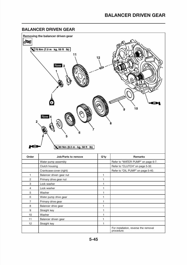
8/12/2019 Yamaha Tenere XT660Z Service Manual
http://slidepdf.com/reader/full/yamaha-tenere-xt660z-service-manual 239/398
BALANCER DRIVEN GEAR
REMOVING THE BALANCER DRIVEN
GEAR AND BALANCER DRIVE GEAR
1. Straighten the lock washer tab.2. Loosen:
INSTALLING THE BALANCER DRIVEN
GEAR AND BALANCER DRIVE GEAR
1. Install:• Washer
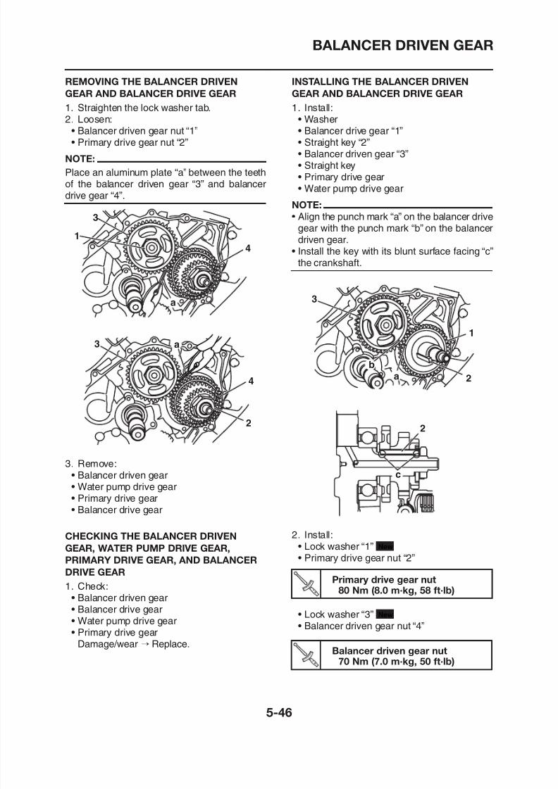
8/12/2019 Yamaha Tenere XT660Z Service Manual
http://slidepdf.com/reader/full/yamaha-tenere-xt660z-service-manual 240/398
• Balancer driven gear nut “1”• Primary drive gear nut “2”
NOTE:
Place an aluminum plate “a” between the teethof the balancer driven gear “3” and balancerdrive gear “4”.
3
4
a
1
3
4
a
• Balancer drive gear “1”• Straight key “2”• Balancer driven gear “3”• Straight key• Primary drive gear• Water pump drive gear
NOTE:
• Align the punch mark “a” on the balancer drivegear with the punch mark “b” on the balancerdriven gear.
• Install the key with its blunt surface facing “c”the crankshaft.
3
1
2a
b
BALANCER DRIVEN GEAR
NOTE:
Place an aluminum plate “a” between the teethof the balancer drive gear and balancer drivengear.
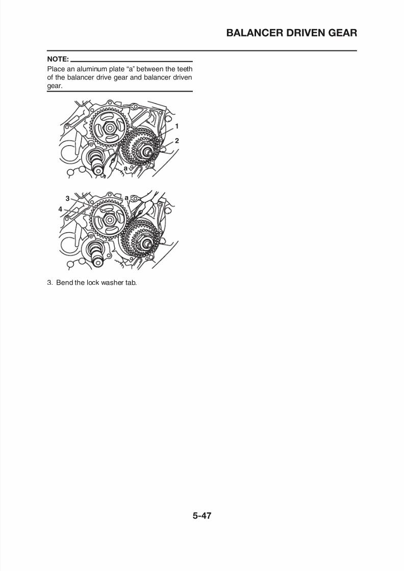
8/12/2019 Yamaha Tenere XT660Z Service Manual
http://slidepdf.com/reader/full/yamaha-tenere-xt660z-service-manual 241/398
3. Bend the lock washer tab.
4
3 a
1
2
a
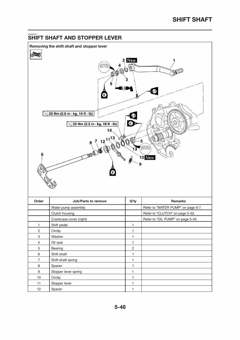
8/12/2019 Yamaha Tenere XT660Z Service Manual
http://slidepdf.com/reader/full/yamaha-tenere-xt660z-service-manual 242/398
SHIFT SHAFT
Removing the shift shaft and stopper lever
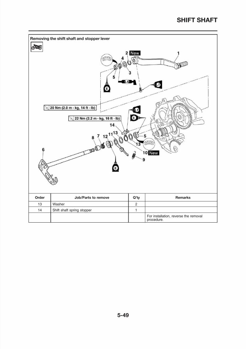
8/12/2019 Yamaha Tenere XT660Z Service Manual
http://slidepdf.com/reader/full/yamaha-tenere-xt660z-service-manual 243/398
SHIFT SHAFT
EAS00329
CHECKING THE SHIFT SHAFT
1. Check:• Shift shaft “1”
Shift h ft l “2”
NOTE:
• Hook the ends of the stopper lever spring on-to the stopper lever and the crankcase boss“4”.
M h th t l ith th hift d
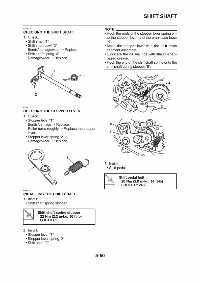
8/12/2019 Yamaha Tenere XT660Z Service Manual
http://slidepdf.com/reader/full/yamaha-tenere-xt660z-service-manual 244/398
• Shift shaft pawl “2”Bends/damage/wear → Replace.
• Shift shaft spring “3”Damage/wear → Replace.
EAS00330
CHECKING THE STOPPER LEVER
1. Check:• Stopper lever “1”
Bends/damage → Replace.Roller turns roughly → Replace the stopperlever.
• Stopper lever spring “2”Damage/wear → Replace.
2
1
3
• Mesh the stopper lever with the shift drumsegment assembly.
• Lubricate the oil seal lips with lithium-soap-based grease.
• Hook the end of the shift shaft spring onto theshift shaft spring stopper “5”.
3
5
1
4
2
STARTER CLUTCH AND A.C. MAGNETO
Removing the starter clutch and A.C. magneto
EAS00341
STARTER CLUTCH AND A.C. MAGNETO
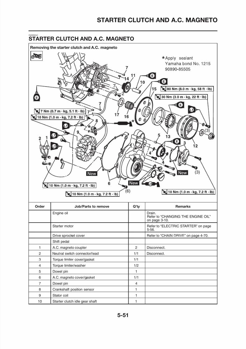
8/12/2019 Yamaha Tenere XT660Z Service Manual
http://slidepdf.com/reader/full/yamaha-tenere-xt660z-service-manual 245/398
STARTER CLUTCH AND A.C. MAGNETO
Removing the starter clutch and A.C. magneto
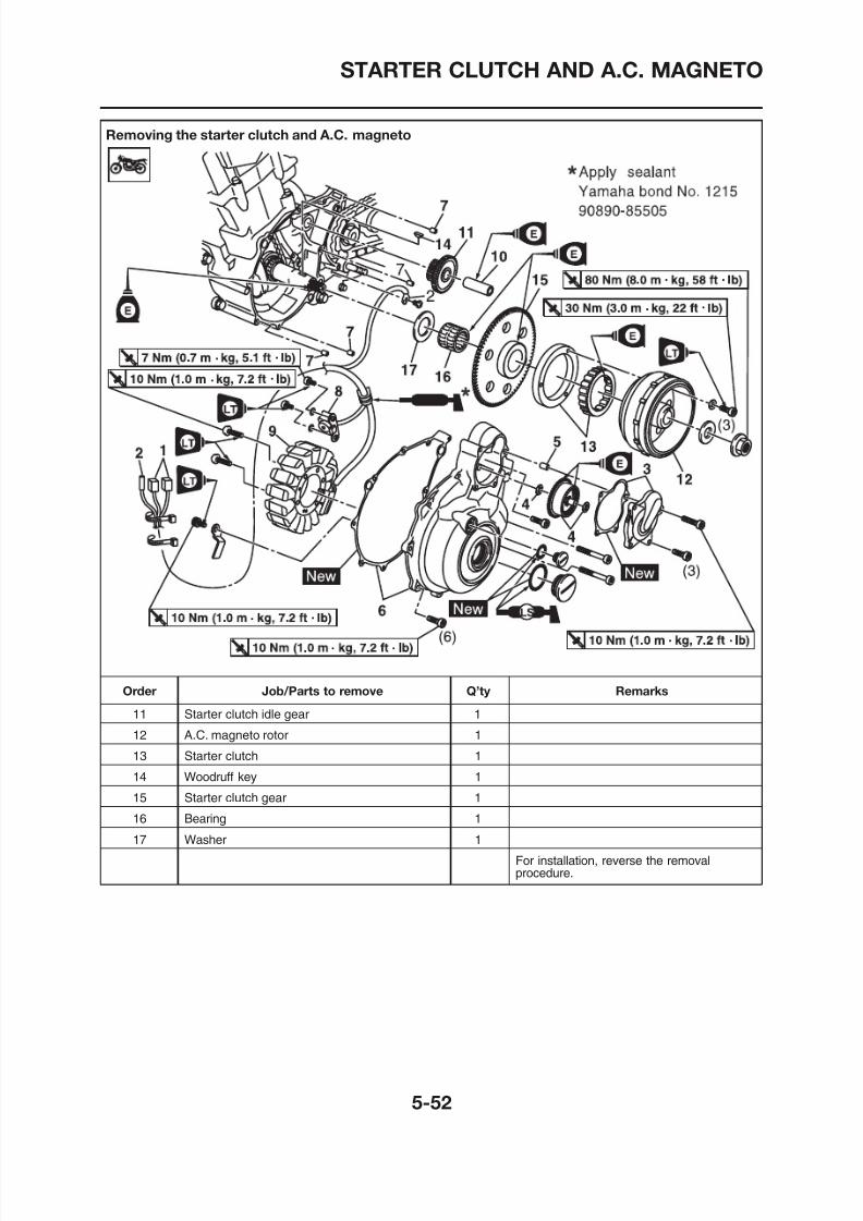
8/12/2019 Yamaha Tenere XT660Z Service Manual
http://slidepdf.com/reader/full/yamaha-tenere-xt660z-service-manual 246/398
STARTER CLUTCH AND A.C. MAGNETO
EAS00346
REMOVING THE A.C. MAGNETO ROTOR
1. Remove:• Torque limiter cover
a
3
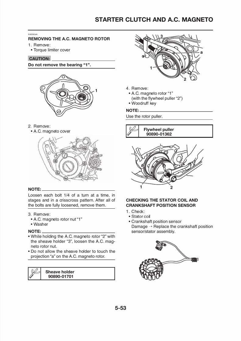
8/12/2019 Yamaha Tenere XT660Z Service Manual
http://slidepdf.com/reader/full/yamaha-tenere-xt660z-service-manual 247/398
CAUTION:
Do not remove the bearing “1”.
2. Remove:• A.C. magneto cover
1
1
2
4. Remove:• A.C. magneto rotor “1”
(with the flywheel puller “2”)• Woodruff key
NOTE:
Use the rotor puller.
Flywheel puller90890-01362
STARTER CLUTCH AND A.C. MAGNETO
EAS00351
CHECKING THE STARTER CLUTCH
1. Check:• Starter clutch rollers “1”
Damage/wear → Replace
A
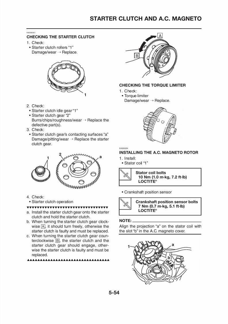
8/12/2019 Yamaha Tenere XT660Z Service Manual
http://slidepdf.com/reader/full/yamaha-tenere-xt660z-service-manual 248/398
Damage/wear → Replace.
2. Check:• Starter clutch idle gear “1”• Starter clutch gear “2”
Burrs/chips/roughness/wear → Replace thedefective part(s).
3. Check:• Starter clutch gear’s contacting surfaces “a”
Damage/pitting/wear → Replace the starterclutch gear.
12
a
1
CHECKING THE TORQUE LIMITER
1. Check:• Torque limiter
Damage/wear → Replace.
EAS00354
INSTALLING THE A.C. MAGNETO ROTOR
1. Install:• Stator coil “1”
B
STARTER CLUTCH AND A.C. MAGNETO
2. Apply:• Yamaha bond No. 1215 “1” (into the slits)
Yamaha bond No. 121590890 85505
NOTE:
• While holding the A.C. magneto rotor “2” withthe sheave holder “3”, tighten the A.C. mag-neto rotor nut.
• Do not allow the sheave holder to touch the
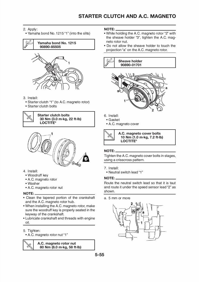
8/12/2019 Yamaha Tenere XT660Z Service Manual
http://slidepdf.com/reader/full/yamaha-tenere-xt660z-service-manual 249/398
90890-85505
3. Install:• Starter clutch “1” (to A.C. magneto rotor)• Starter clutch bolts
1
Starter clutch bolts30 Nm (3.0 m·kg, 22 ft·lb)LOCTITE®
• Do not allow the sheave holder to touch theprojection “a” on the A.C. magneto rotor.
Sheave holder90890-01701
6. Install:• Gasket• A.C. magneto cover
1
2
a
3
A.C. magneto cover bolts10 Nm (1.0 m·kg, 7.2 ft·lb)LOCTITE®
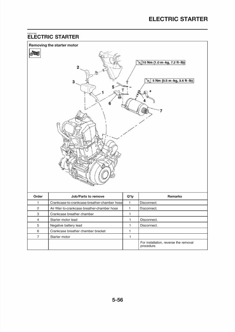
8/12/2019 Yamaha Tenere XT660Z Service Manual
http://slidepdf.com/reader/full/yamaha-tenere-xt660z-service-manual 250/398
ELECTRIC STARTER
Disassembling the starter motor
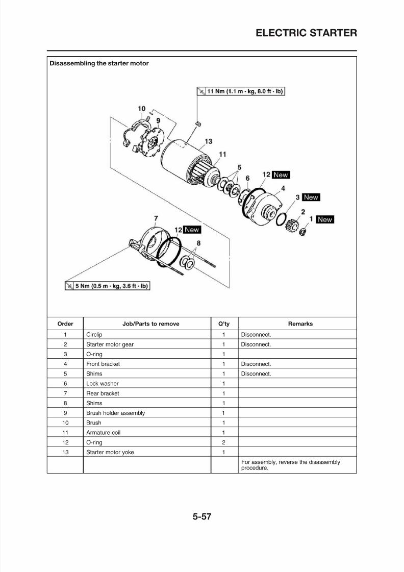
8/12/2019 Yamaha Tenere XT660Z Service Manual
http://slidepdf.com/reader/full/yamaha-tenere-xt660z-service-manual 251/398
ELECTRIC STARTER
EAS24790
CHECKING THE STARTER MOTOR
1. Check:• Commutator
Dirt → Clean with 600 grit sandpaper Pocket tester
a. Measure the armature assembly resistanceswith the pocket tester.
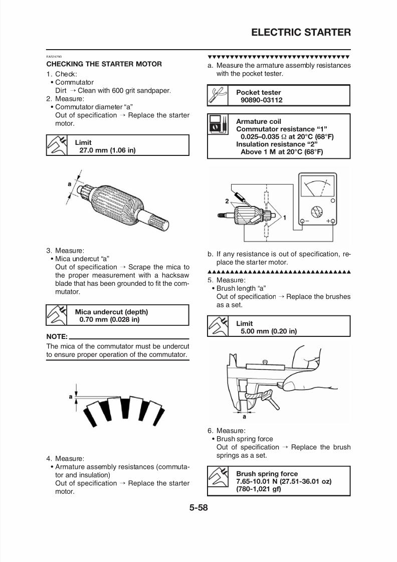
8/12/2019 Yamaha Tenere XT660Z Service Manual
http://slidepdf.com/reader/full/yamaha-tenere-xt660z-service-manual 252/398
Dirt → Clean with 600 grit sandpaper.2. Measure:
• Commutator diameter “a”Out of specification → Replace the startermotor.
Limit27.0 mm (1.06 in)
3. Measure:• Mica undercut “a”
Out of specification → Scrape the mica tothe proper measurement with a hacksawblade that has been grounded to fit the com-mutator.
Pocket tester90890-03112
Armature coilCommutator resistance “1”
0.025–0.035 Ω at 20°C (68°F)Insulation resistance “2” Above 1 M at 20°C (68°F)
b. If any resistance is out of specification, re-place the starter motor.
5. Measure:• Brush length “a”
ELECTRIC STARTER
3. Install:• Rear bracket
NOTE:
Align the slot “a” in the rear bracket with the tab“b” th b h t
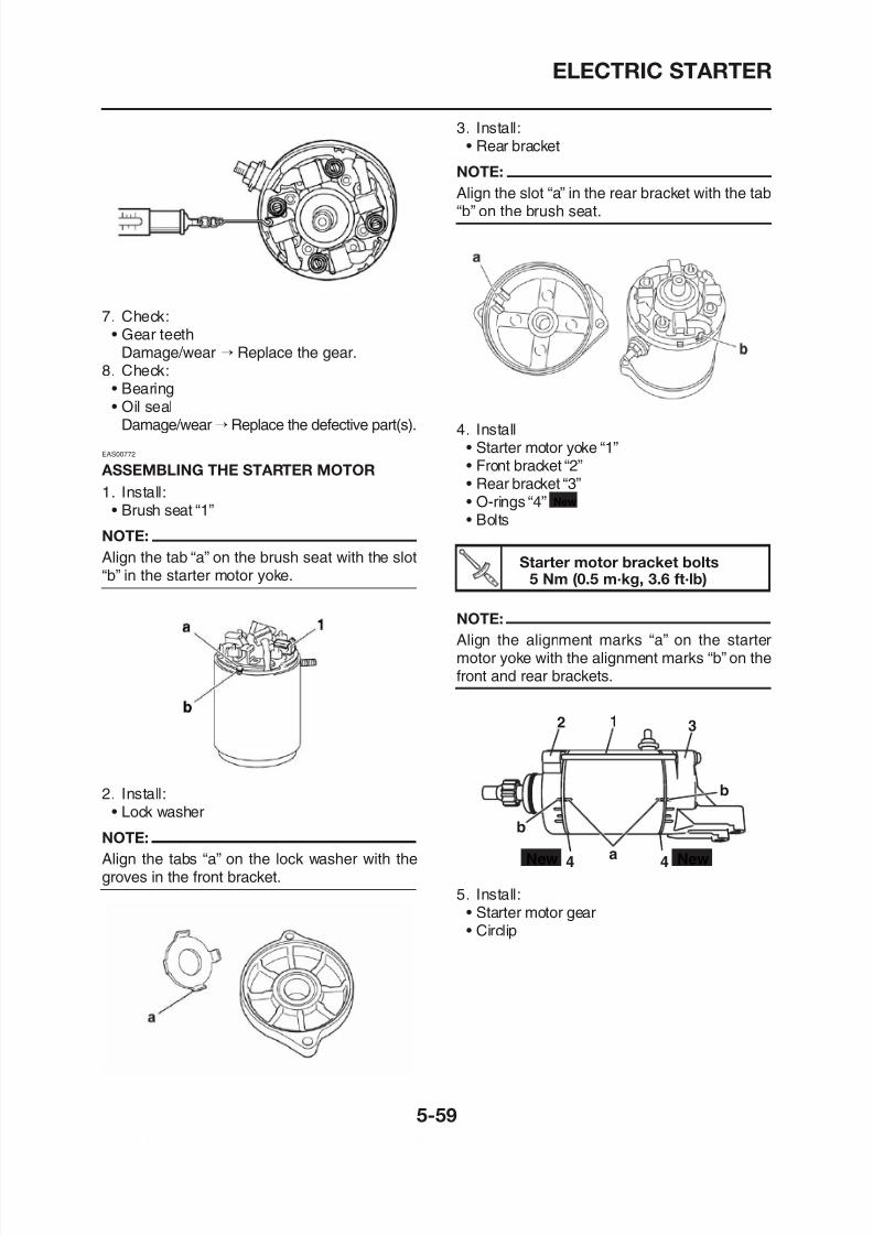
8/12/2019 Yamaha Tenere XT660Z Service Manual
http://slidepdf.com/reader/full/yamaha-tenere-xt660z-service-manual 253/398
7. Check:• Gear teeth
Damage/wear → Replace the gear.8. Check:
• Bearing• Oil seal
Damage/wear→Replace the defective part(s).
EAS00772
ASSEMBLING THE STARTER MOTOR
1. Install:• Brush seat “1”
NOTE:
Align the tab “a” on the brush seat with the slot“b” in the starter motor yoke.
Align the slot a in the rear bracket with the tab“b” on the brush seat.
4. Install• Starter motor yoke “1”• Front bracket “2”• Rear bracket “3”
• O-rings “4”• Bolts
New
Starter motor bracket bolts5 Nm (0.5 m·kg, 3.6 ft·lb)
NOTE:
Align the alignment marks “a” on the starter
CRANKCASE
Separating the crankcase
CRANKCASE
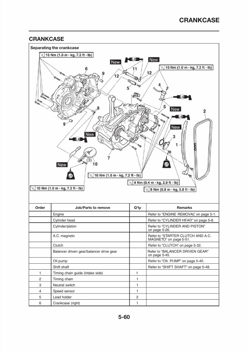
8/12/2019 Yamaha Tenere XT660Z Service Manual
http://slidepdf.com/reader/full/yamaha-tenere-xt660z-service-manual 254/398
CRANKCASE
Separating the crankcase
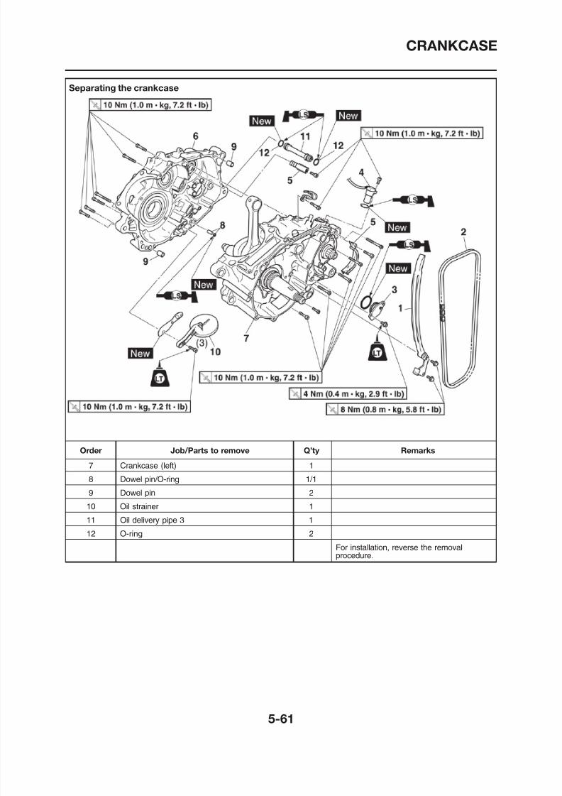
8/12/2019 Yamaha Tenere XT660Z Service Manual
http://slidepdf.com/reader/full/yamaha-tenere-xt660z-service-manual 255/398
CRANKCASE
Removing the crankcase bearings
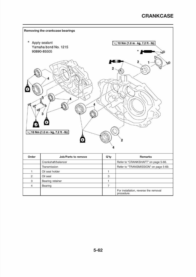
8/12/2019 Yamaha Tenere XT660Z Service Manual
http://slidepdf.com/reader/full/yamaha-tenere-xt660z-service-manual 256/398
CRANKCASE
SEPARATING THE CRANKCASE
1. Separate:• Right crankcase “1”• Left crankcase “2”
CHECKING THE OIL STRAINER AND OIL
DELIVERY PIPE 3
1. Check:• Oil strainer
Damage → Replace
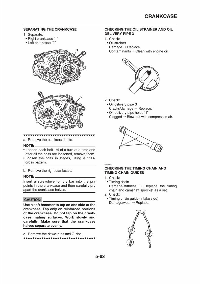
8/12/2019 Yamaha Tenere XT660Z Service Manual
http://slidepdf.com/reader/full/yamaha-tenere-xt660z-service-manual 257/398
2
1
a. Remove the crankcase bolts.
NOTE:
Damage Replace.Contaminants→ Clean with engine oil.
2. Check:• Oil delivery pipe 3
Cracks/damage → Replace.• Oil delivery pipe holes “1”
Clogged → Blow out with compressed air.
1
CRANKCASE
EAS00401
CHECKING THE BEARINGS AND OIL
SEALS
1. Check:
• Bearings
Bearing retainer bolts10 Nm (1.0 m·kg, 7.2 ft·lb)
NOTE:
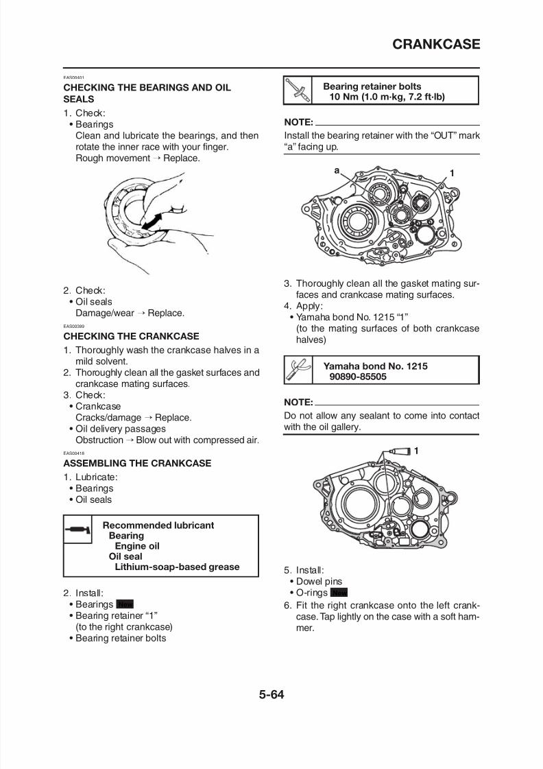
8/12/2019 Yamaha Tenere XT660Z Service Manual
http://slidepdf.com/reader/full/yamaha-tenere-xt660z-service-manual 258/398
BearingsClean and lubricate the bearings, and thenrotate the inner race with your finger.Rough movement → Replace.
2. Check:• Oil seals
Damage/wear → Replace.EAS00399
CHECKING THE CRANKCASE
1. Thoroughly wash the crankcase halves in amild solvent.
2. Thoroughly clean all the gasket surfaces andcrankcase mating surfaces.
3. Check:
NOTE:Install the bearing retainer with the “OUT” mark“a” facing up.
3. Thoroughly clean all the gasket mating sur-faces and crankcase mating surfaces.
4. Apply:
• Yamaha bond No. 1215 “1”(to the mating surfaces of both crankcasehalves)
a 1
Yamaha bond No. 121590890-85505
NOTE:
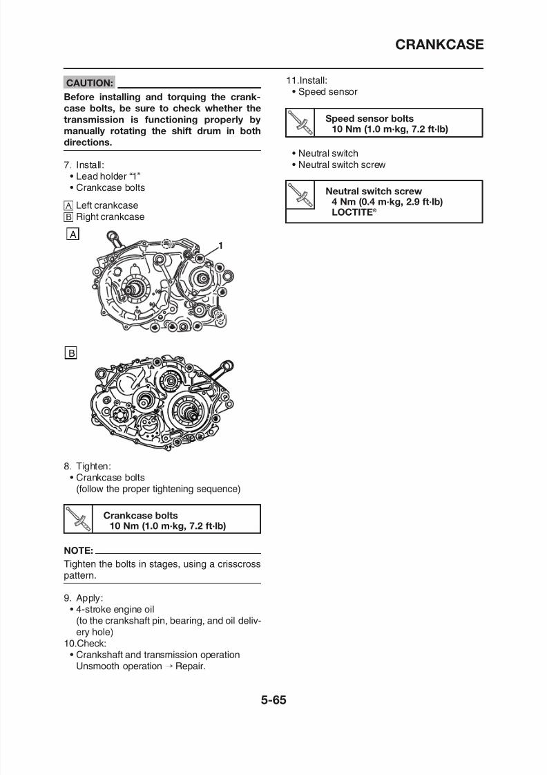
8/12/2019 Yamaha Tenere XT660Z Service Manual
http://slidepdf.com/reader/full/yamaha-tenere-xt660z-service-manual 259/398
CRANKSHAFT
Removing the crankshaft and balancer
EAS00381
CRANKSHAFT
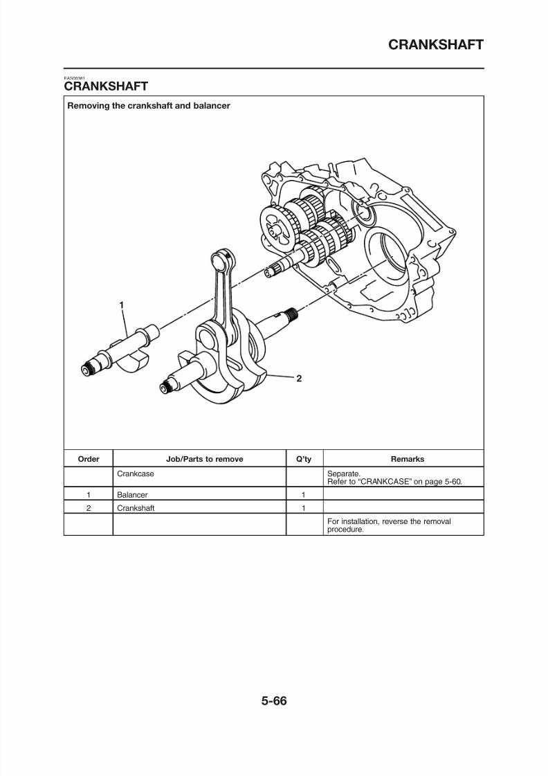
8/12/2019 Yamaha Tenere XT660Z Service Manual
http://slidepdf.com/reader/full/yamaha-tenere-xt660z-service-manual 260/398
1
2
CRANKSHAFT
EAS00388
REMOVING THE CRANKSHAFT
ASSEMBLY
1. Remove:
• Crankshaft “1”
3. Measure:• Crankshaft runout “c”
Out of specification → Replace the crank-shaft, bearing or both.
NOTE:
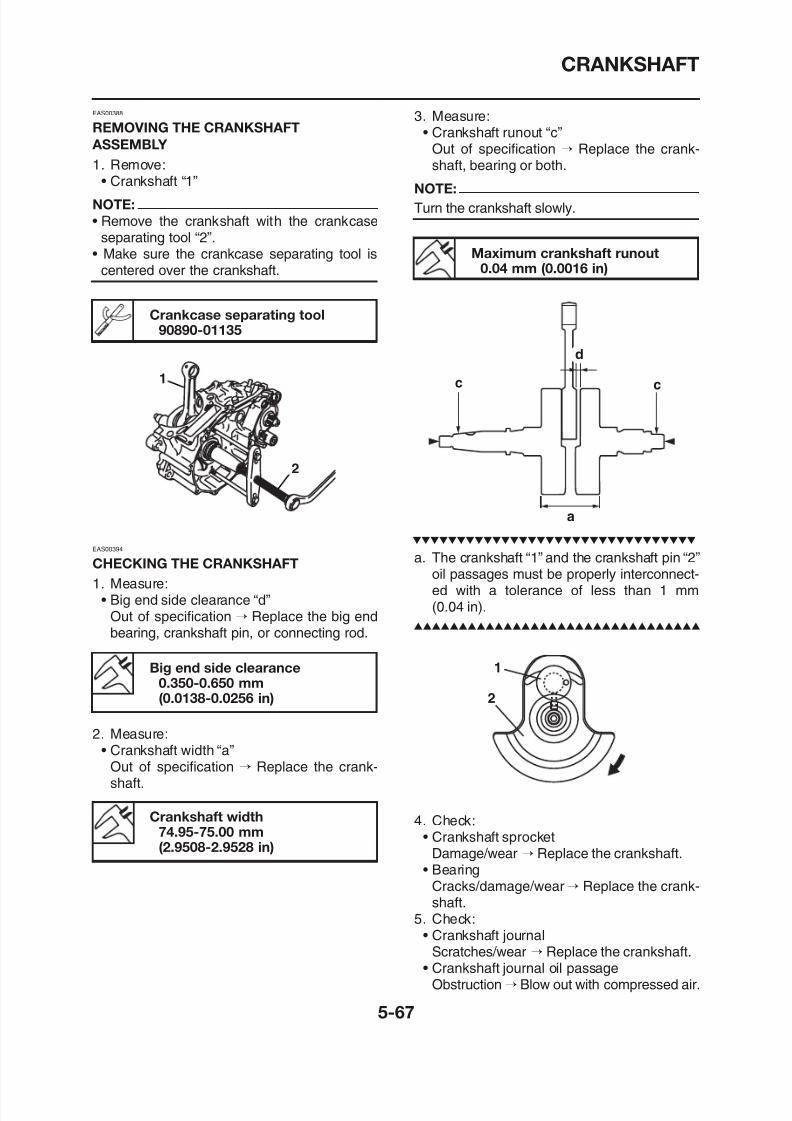
8/12/2019 Yamaha Tenere XT660Z Service Manual
http://slidepdf.com/reader/full/yamaha-tenere-xt660z-service-manual 261/398
NOTE:
• Remove the crankshaft with the crankcaseseparating tool “2”.
• Make sure the crankcase separating tool iscentered over the crankshaft.
Crankcase separating tool90890-01135
EAS00394
CHECKING THE CRANKSHAFT
1. Measure:
1
2
Turn the crankshaft slowly.
a. The crankshaft “1” and the crankshaft pin “2”oil passages must be properly interconnect-
Maximum crankshaft runout0.04 mm (0.0016 in)
c
d
c
a
CRANKSHAFT
EAS00408
INSTALLING THE CRANKSHAFT
1. Install:• Crankshaft “1”
NOTE:
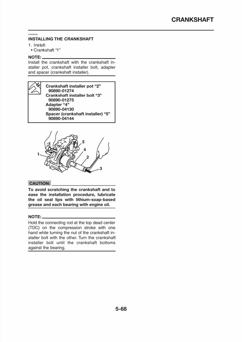
8/12/2019 Yamaha Tenere XT660Z Service Manual
http://slidepdf.com/reader/full/yamaha-tenere-xt660z-service-manual 262/398
Install the crankshaft with the crankshaft in-staller pot, crankshaft installer bolt, adapterand spacer (crankshaft installer).
Crankshaft installer pot “2”90890-01274
Crankshaft installer bolt “3”90890-01275
Adapter “4”90890-04130
Spacer (crankshaft installer) “5”90890-04144
1
5
4
2
3
TRANSMISSION
Removing the transmission, shift drum, and shift forks
EAS00419
TRANSMISSION
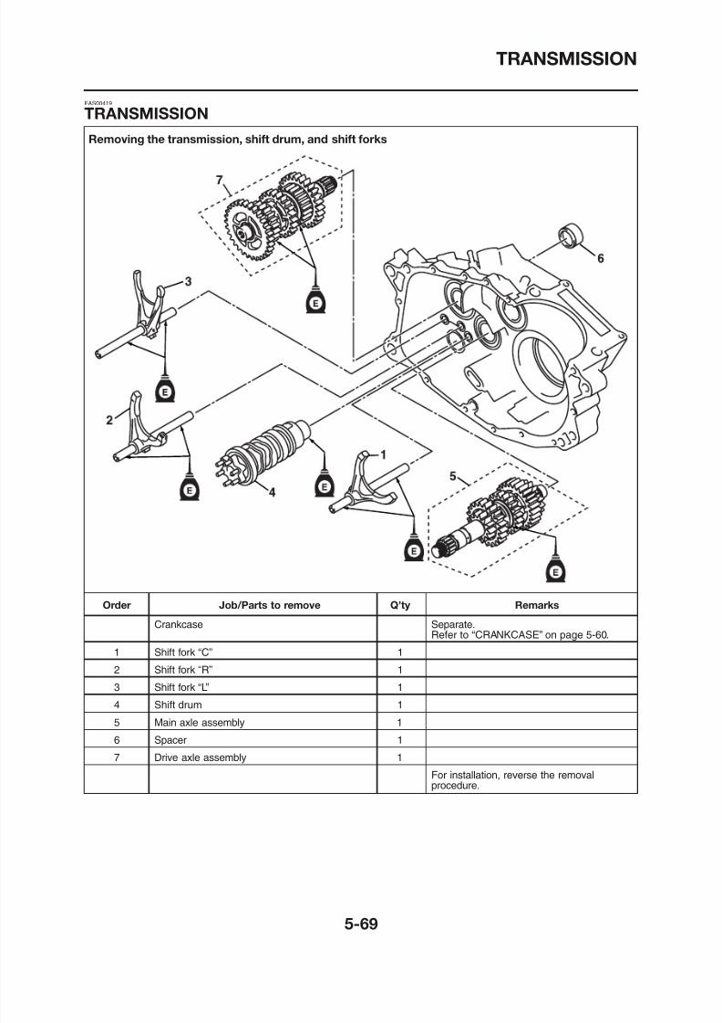
8/12/2019 Yamaha Tenere XT660Z Service Manual
http://slidepdf.com/reader/full/yamaha-tenere-xt660z-service-manual 263/398
TRANSMISSION
Disassembling the main axle
98
7
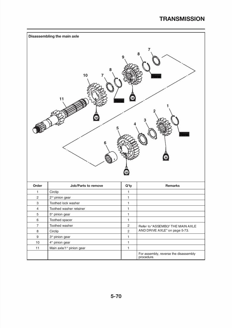
8/12/2019 Yamaha Tenere XT660Z Service Manual
http://slidepdf.com/reader/full/yamaha-tenere-xt660z-service-manual 264/398
M
M
M
New
New
New
M
11
10 7
8
9
6
5
4
3
2
1
TRANSMISSION
Disassembling the drive axle
8
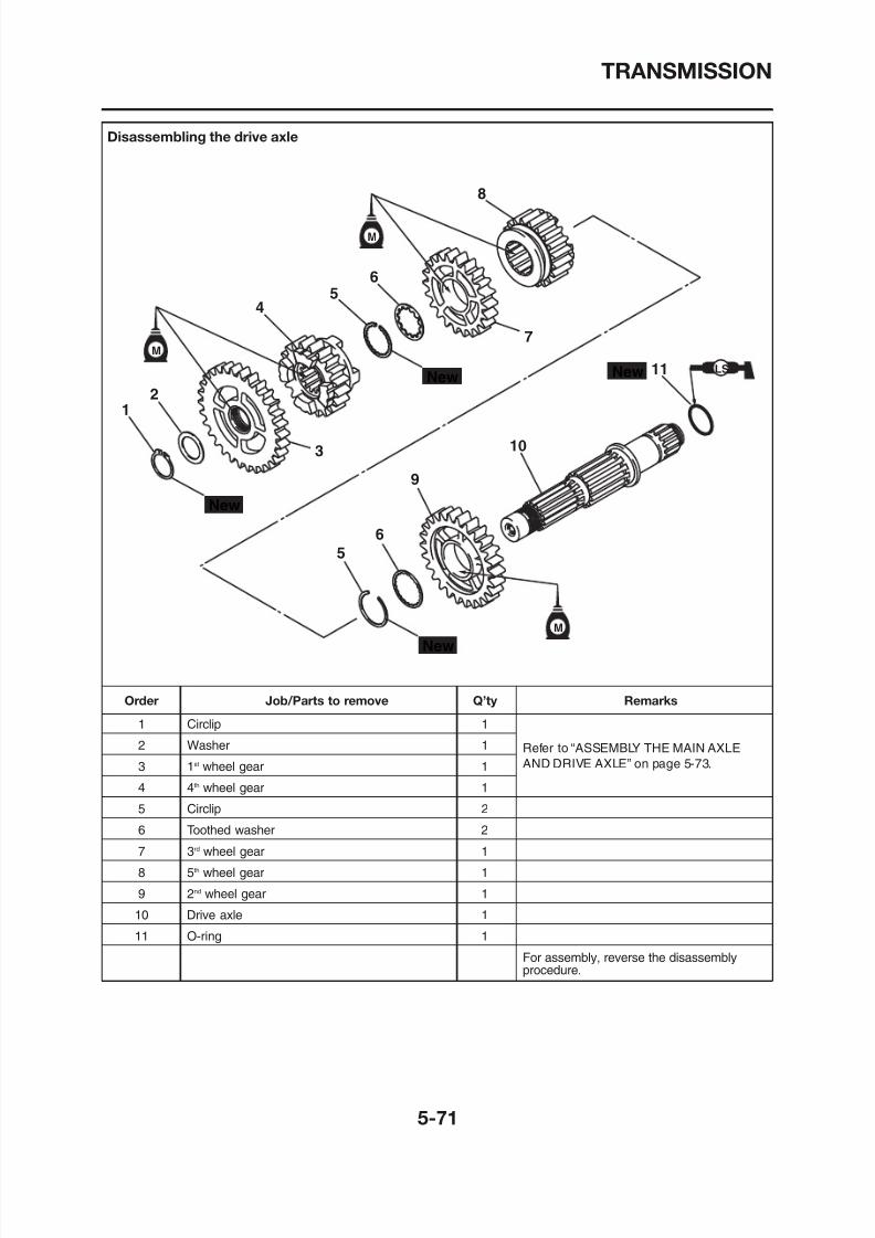
8/12/2019 Yamaha Tenere XT660Z Service Manual
http://slidepdf.com/reader/full/yamaha-tenere-xt660z-service-manual 265/398
M
M
M
New
New
New
New LS
1
2
45
6
7
5
3
6
9
10
11
TRANSMISSION
EAS00421
CHECKING THE SHIFT FORKS
The following procedure applies to all of theshift forks.
1. Check:• Shift fork cam follower “1”
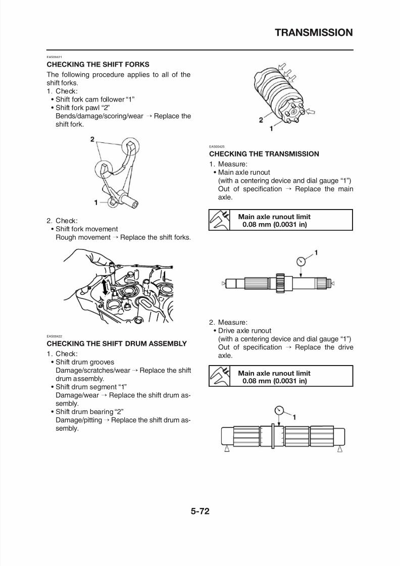
8/12/2019 Yamaha Tenere XT660Z Service Manual
http://slidepdf.com/reader/full/yamaha-tenere-xt660z-service-manual 266/398
• Shift fork cam follower 1• Shift fork pawl “2”
Bends/damage/scoring/wear → Replace theshift fork.
2. Check:
• Shift fork movementRough movement → Replace the shift forks.
EAS00425
CHECKING THE TRANSMISSION
1. Measure:• Main axle runout
(with a centering device and dial gauge “1”)Out of specification → Replace the mainaxle.
Main axle runout limit0.08 mm (0.0031 in)
TRANSMISSION
3. Check:• Transmission gears
Blue discoloration/pitting/wear → Replacethe defective gear(s).
• Transmission gear dogsCracks/damage/rounded edges → Replace
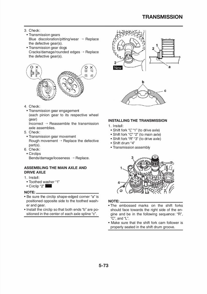
8/12/2019 Yamaha Tenere XT660Z Service Manual
http://slidepdf.com/reader/full/yamaha-tenere-xt660z-service-manual 267/398
Cracks/damage/rounded edges → Replacethe defective gear(s).
4. Check:• Transmission gear engagement
(each pinion gear to its respective wheel
gear)Incorrect → Reassemble the transmissionaxle assemblies.
5. Check:• Transmission gear movement
Rough movement → Replace the defectivepart(s).
6. Check:• Circlips
INSTALLING THE TRANSMISSION1. Install:
• Shift fork “L” “1” (to drive axle)• Shift fork “C” “2” (to main axle)• Shift fork “R” “3” (to drive axle)• Shift drum “4”• Transmission assembly
TRANSMISSION
2. Check:• Shift operation
Unsmooth operation → Repair.
NOTE:
• Apply engine oil to each gear and bearing
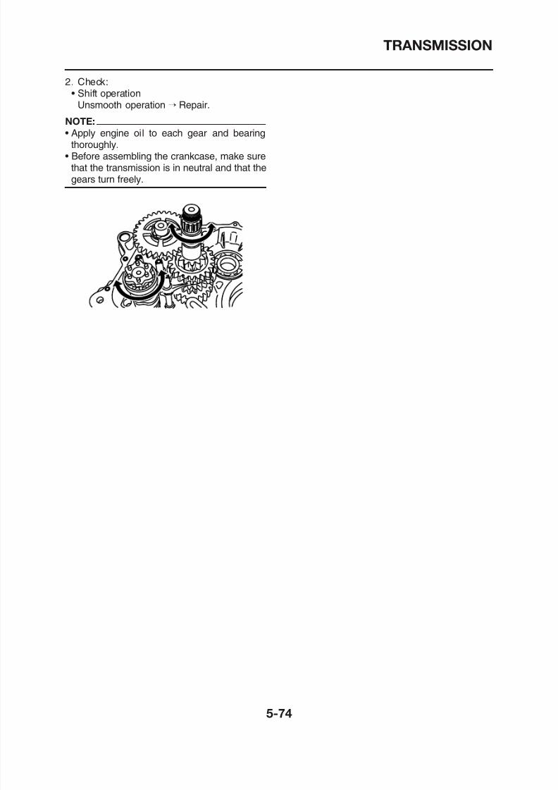
8/12/2019 Yamaha Tenere XT660Z Service Manual
http://slidepdf.com/reader/full/yamaha-tenere-xt660z-service-manual 268/398
thoroughly.• Before assembling the crankcase, make sure
that the transmission is in neutral and that thegears turn freely.
COOLING SYSTEM
RADIATOR ..................................................................................................... 6-1
CHECKING THE RADIATOR................................................................... 6-2INSTALLING THE RADIATOR 6 2
8/12/2019 Yamaha Tenere XT660Z Service Manual
http://slidepdf.com/reader/full/yamaha-tenere-xt660z-service-manual 269/398
INSTALLING THE RADIATOR ................................................................. 6-2
THERMOSTAT................................................................................................ 6-4CHECKING THE THERMOSTAT ............................................................. 6-5INSTALLING THE THERMOSTAT ........................................................... 6-5
WATER PUMP................................................................................................ 6-7
DISASSEMBLING THE WATER PUMP................................................... 6-9CHECKING THE WATER PUMP............................................................. 6-9ASSEMBLING THE WATER PUMP.........................................................6-10INSTALLING THE WATER PUMP ........................................................... 6-11

8/12/2019 Yamaha Tenere XT660Z Service Manual
http://slidepdf.com/reader/full/yamaha-tenere-xt660z-service-manual 270/398
RADIATOR
Removing the radiator
EAS00454
RADIATOR
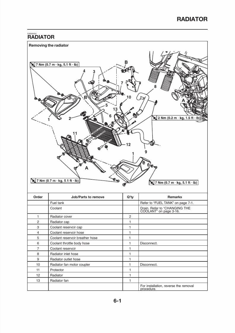
8/12/2019 Yamaha Tenere XT660Z Service Manual
http://slidepdf.com/reader/full/yamaha-tenere-xt660z-service-manual 271/398
RADIATOR
EAS00455
CHECKING THE RADIATOR
1. Check:• Radiator fins
Obstruction→ Clean.Apply compressed air to the rear of the radi-
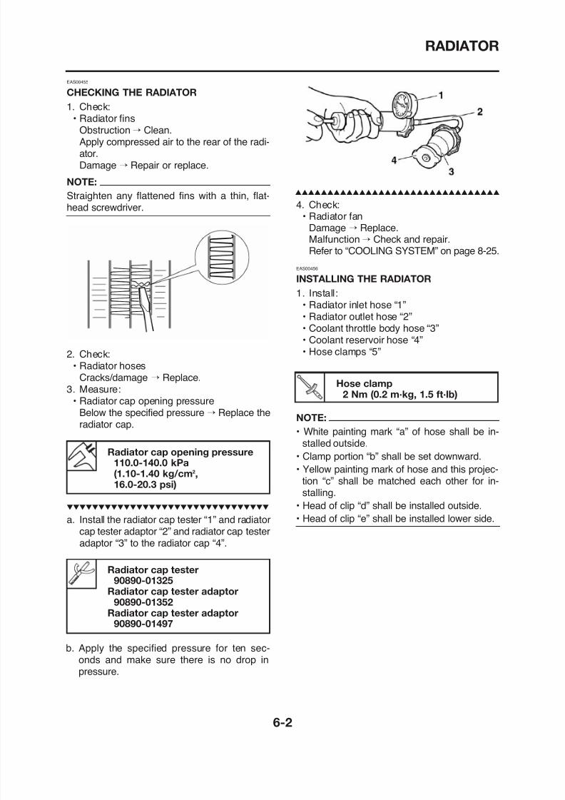
8/12/2019 Yamaha Tenere XT660Z Service Manual
http://slidepdf.com/reader/full/yamaha-tenere-xt660z-service-manual 272/398
Apply compressed air to the rear of the radiator.Damage → Repair or replace.
NOTE:
Straighten any flattened fins with a thin, flat-head screwdriver.
2. Check:• Radiator hoses
Cracks/damage → Replace.3. Measure:
• Radiator cap opening pressureBelow the specified pressure → Replace the
4. Check:• Radiator fan
Damage → Replace.Malfunction→ Check and repair.Refer to “COOLING SYSTEM” on page 8-25.
EAS00456
INSTALLING THE RADIATOR
1. Install:• Radiator inlet hose “1”• Radiator outlet hose “2”
• Coolant throttle body hose “3”• Coolant reservoir hose “4”• Hose clamps “5”
NOTE:
Hose clamp2 Nm (0.2 m·kg, 1.5 ft·lb)
RADIATOR
1
2
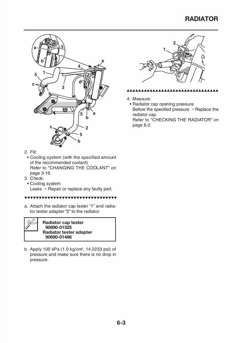
8/12/2019 Yamaha Tenere XT660Z Service Manual
http://slidepdf.com/reader/full/yamaha-tenere-xt660z-service-manual 273/398
2. Fill:• Cooling system (with the specified amount
of the recommended coolant)Refer to “CHANGING THE COOLANT” onpage 3-16.
3. Check:
4. Measure:• Radiator cap opening pressure
Bellow the specified pressure → Replace theradiator cap.Refer to “CHECKING THE RADIATOR” onpage 6-2.
THERMOSTAT
Removing the thermostat
EAS00460
THERMOSTAT
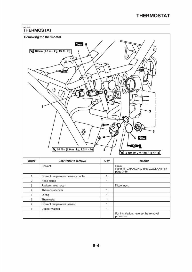
8/12/2019 Yamaha Tenere XT660Z Service Manual
http://slidepdf.com/reader/full/yamaha-tenere-xt660z-service-manual 274/398
THERMOSTAT
EAS00462
CHECKING THE THERMOSTAT
1. Check:• Thermostat “1”
Does not open at 71-85 °C (159.8-185 °F) →Replace.
2. Check:• Thermostat cover• Thermostat housing (cylinder head)
Cracks/damage → Replace.
EAS00466
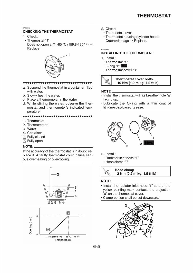
8/12/2019 Yamaha Tenere XT660Z Service Manual
http://slidepdf.com/reader/full/yamaha-tenere-xt660z-service-manual 275/398
p
a. Suspend the thermostat in a container filledwith water.
b. Slowly heat the water.c. Place a thermometer in the water.d. While stirring the water, observe the ther-
mostat and thermometer’s indicated tem-
perature.
1. Thermostat2. Thermometer3. Water4. Container å Fully closed ∫ Fully open
EAS00466
INSTALLING THE THERMOSTAT
1. Install:• Thermostat “1”• O-ring “2”• Thermostat cover “3”
New
Thermostat cover bolts10 Nm (1.0 m·kg, 7.2 ft·lb)
NOTE:
• Install the thermostat with its breather hole “a”facing up.
• Lubricate the O-ring with a thin coat oflithium-soap-based grease.
New2
1
a
THERMOSTAT
3. Install:• Copper washer• Coolant temperature sensor
New
Coolant temperature sensor18 Nm (1.8 m·kg, 13 ft·lb)
8/12/2019 Yamaha Tenere XT660Z Service Manual
http://slidepdf.com/reader/full/yamaha-tenere-xt660z-service-manual 276/398
18 Nm (1.8 m kg, 13 ft lb)
CAUTION:
Use extreme care when handling the cool-
ant temperature sensor. Replace the sen-
sor if it is dropped or subjected to a strong
impact.
4. Fill:• Cooling system (with the specified amount
of the recommended coolant)Refer to “CHANGING THE COOLANT” onpage 3-16.
5. Check:• Cooling system
Leaks→
Repair or replace any faulty part.6. Measure:• Radiator cap opening pressure
Below the specified pressure → Replace theradiator cap.Refer to “CHECKING THE RADIATOR” onpage 6-2.
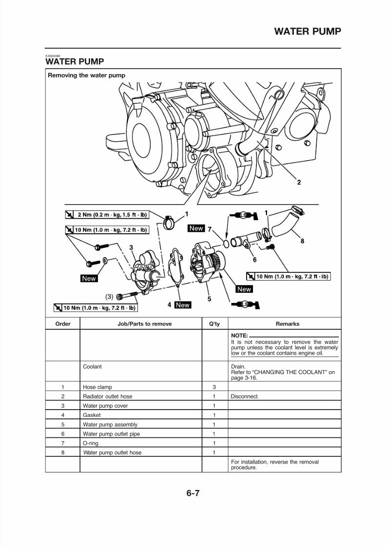
8/12/2019 Yamaha Tenere XT660Z Service Manual
http://slidepdf.com/reader/full/yamaha-tenere-xt660z-service-manual 277/398
WATER PUMP
Disassembling the water pump
New
LS
10
9
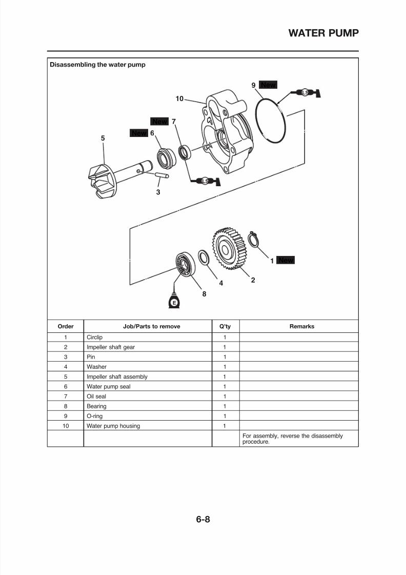
8/12/2019 Yamaha Tenere XT660Z Service Manual
http://slidepdf.com/reader/full/yamaha-tenere-xt660z-service-manual 278/398
New
New
New
E
LS
5
6
7
3
8
4 2
1
WATER PUMP
EAS00470
DISASSEMBLING THE WATER PUMP
1. Remove:• Water pump seal “1”
NOTE:
Tap out the water pump seal from water pump
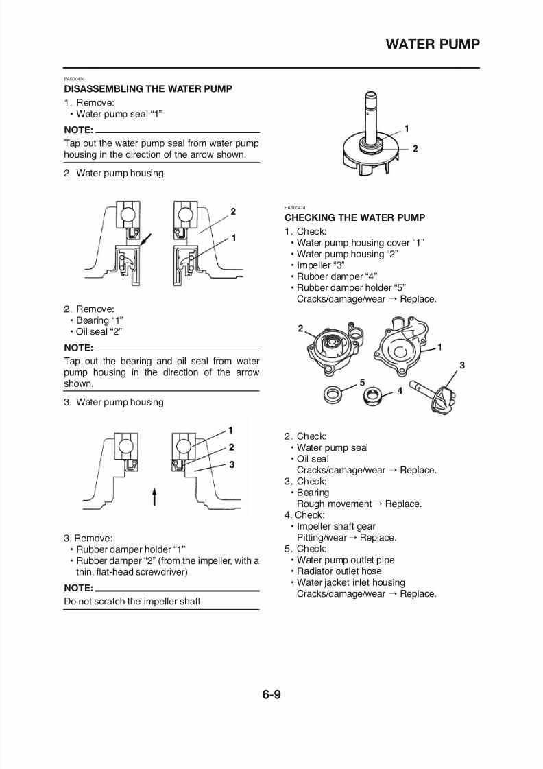
8/12/2019 Yamaha Tenere XT660Z Service Manual
http://slidepdf.com/reader/full/yamaha-tenere-xt660z-service-manual 279/398
Tap out the water pump seal from water pumphousing in the direction of the arrow shown.
2. Water pump housing
2. Remove:
• Bearing “1”• Oil seal “2”
NOTE:
Tap out the bearing and oil seal from waterpump housing in the direction of the arrowshown.
3. Water pump housing
EAS00474
CHECKING THE WATER PUMP1. Check:
• Water pump housing cover “1”• Water pump housing “2”• Impeller “3”• Rubber damper “4”• Rubber damper holder “5”
Cracks/damage/wear → Replace.
2
1
3
45
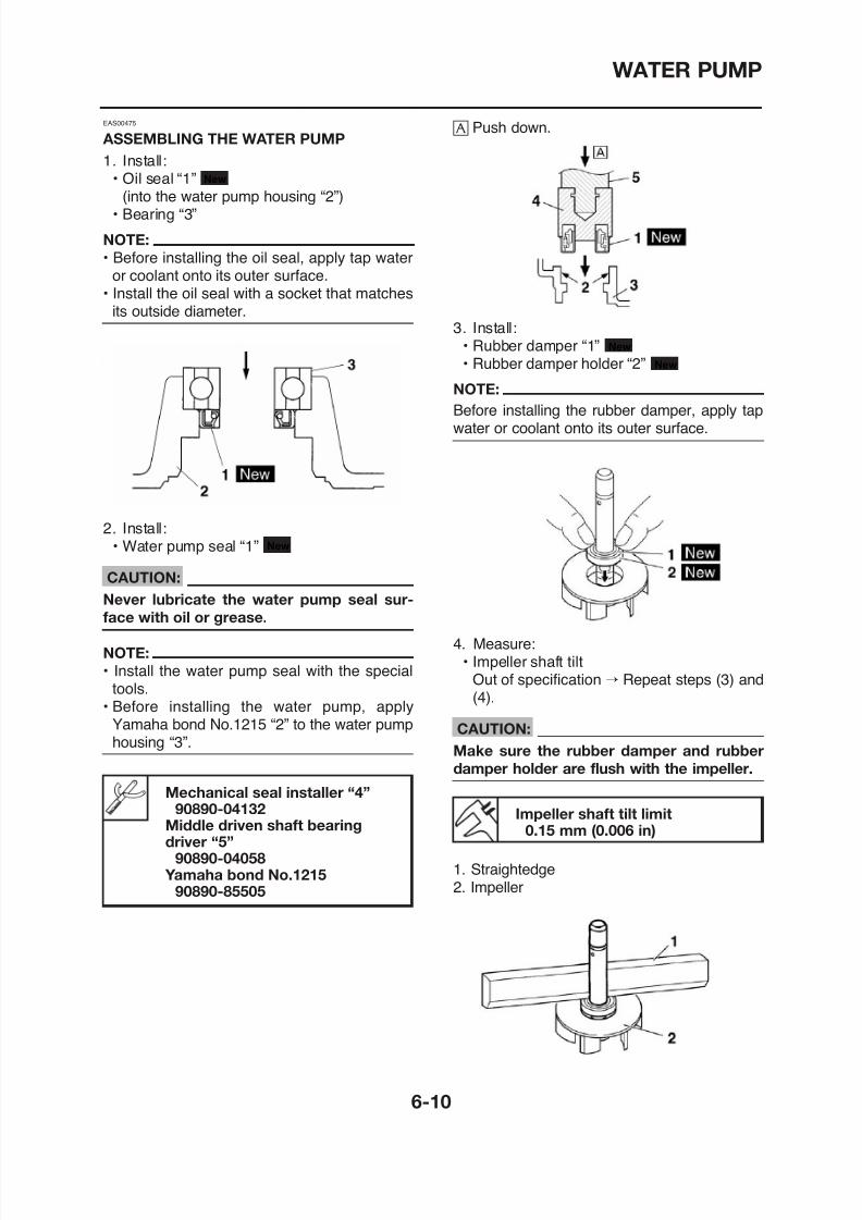
8/12/2019 Yamaha Tenere XT660Z Service Manual
http://slidepdf.com/reader/full/yamaha-tenere-xt660z-service-manual 280/398
WATER PUMP
5. Install:• Impeller shaft assembly “1”• Washer• Pin
• Impeller shaft gear• Circlip New
NOTE:
• Install the water pump outlet hose so that itcontacts the projection “a” on the water jacket joint.
• Before installing the water pump outlet pipe,lubricate the O-rings with a thin coat of lith-
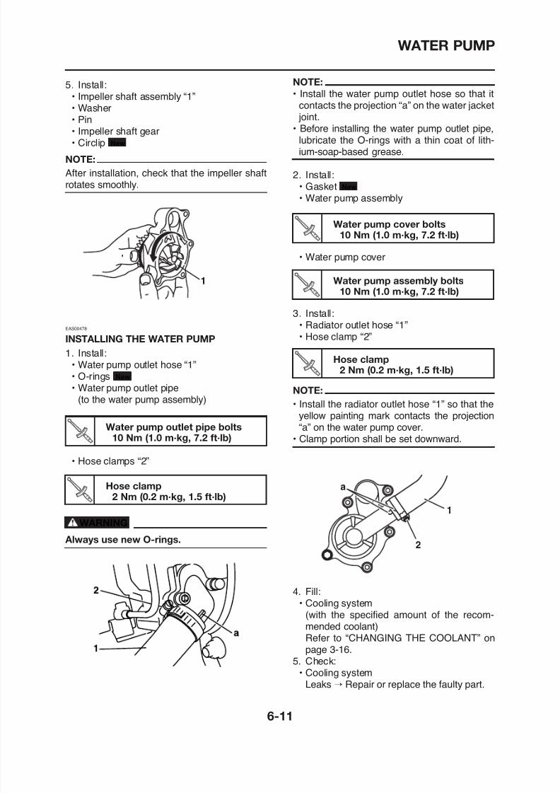
8/12/2019 Yamaha Tenere XT660Z Service Manual
http://slidepdf.com/reader/full/yamaha-tenere-xt660z-service-manual 281/398
p
NOTE:
After installation, check that the impeller shaftrotates smoothly.
EAS00478
INSTALLING THE WATER PUMP
1. Install:• Water pump outlet hose “1”• O-rings• Water pump outlet pipe
(to the water pump assembly)
New
1
ium-soap-based grease.
2. Install:• Gasket• Water pump assembly
New
• Water pump cover
3. Install:
• Radiator outlet hose “1”• Hose clamp “2”
NOTE:
• Install the radiator outlet hose “1” so that theyellow painting mark contacts the projection
Water pump cover bolts10 Nm (1.0 m·kg, 7.2 ft·lb)
Water pump assembly bolts10 Nm (1.0 m·kg, 7.2 ft·lb)
Hose clamp2 Nm (0.2 m·kg, 1.5 ft·lb)
WATER PUMP
6. Measure:• Radiator cap opening pressure
Below the specified pressure → Replace theradiator cap.
Refer to “CHECKING THE RADIATOR” onpage 6-2.
8/12/2019 Yamaha Tenere XT660Z Service Manual
http://slidepdf.com/reader/full/yamaha-tenere-xt660z-service-manual 282/398
FUEL INJECTION SYSTEM
FUEL TANK .................................................................................................... 7-1
REMOVING THE FUEL TANK.................................................................. 7-2REMOVING THE FUEL PUMP 7-2
8/12/2019 Yamaha Tenere XT660Z Service Manual
http://slidepdf.com/reader/full/yamaha-tenere-xt660z-service-manual 283/398
REMOVING THE FUEL PUMP................................................................. 7 2
INSTALLING THE FUEL PUMP ............................................................... 7-3
INSTALLING THE FUEL HOSE................................................................ 7-3
CHECKING THE FUEL SENDER ............................................................ 7-3
THROTTLE BODY ASSEMBLY ..................................................................... 7-4
CHECKING THE FUEL INJECTOR.......................................................... 7-7
CHECKING THE THROTTLE BODY ........................................................ 7-7
INSTALLING THE THROTTLE BODY ASSEMBLY................................... 7-7
CHECKING THE FUEL PUMP................................................................. 7-8
CHECKING THE THROTTLE POSITION SENSOR ................................ 7-9ADJUSTING THE THROTTLE POSITION SENSOR............................... 7-9
AIR INDUCTION SYSTEM ............................................................................7-11
AIR INJECTION........................................................................................7-11AIR CUT-OFF VALVE................................................................................7-11
AIR INDUCTION SYSTEM DIAGRAMS...................................................7-12
AIR CUT-OFF VALVE ASSEMBLY............................................................7-13
CHECKING THE AIR INDUCTION SYSTEM...........................................7-15
FUEL INJECTION SYSTEM...........................................................................7-16
WIRING DIAGRAM...................................................................................7-17

8/12/2019 Yamaha Tenere XT660Z Service Manual
http://slidepdf.com/reader/full/yamaha-tenere-xt660z-service-manual 284/398
Removing the fuel tank and fuel pump
FUEL TANK
FUEL TANK
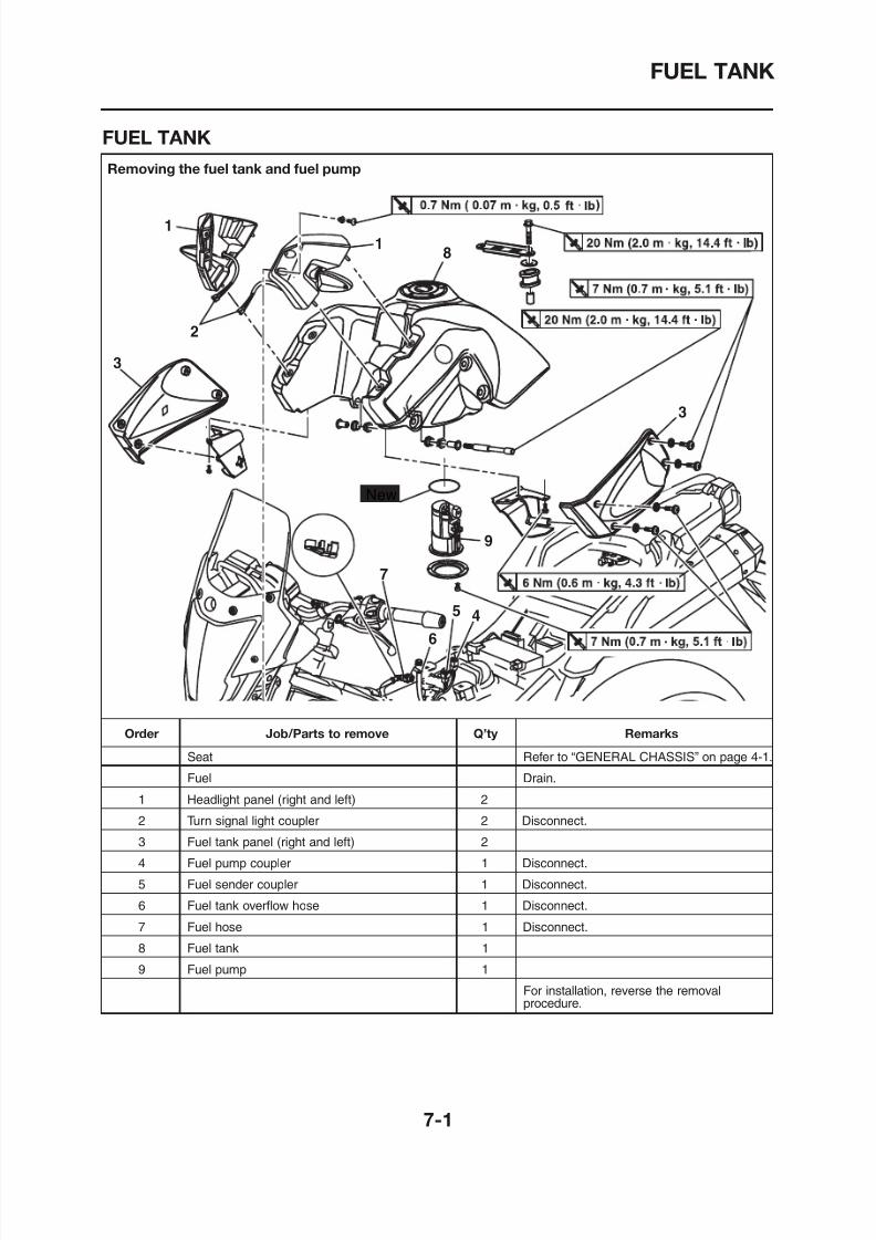
8/12/2019 Yamaha Tenere XT660Z Service Manual
http://slidepdf.com/reader/full/yamaha-tenere-xt660z-service-manual 285/398
FUEL TANK
REMOVING THE FUEL TANK
1. Extract the fuel in the fuel tank through thefuel tank cap with a pump.
2. Remove:
• SeatRefer to “GENERAL CHASSIS” on page
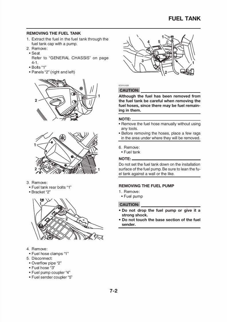
8/12/2019 Yamaha Tenere XT660Z Service Manual
http://slidepdf.com/reader/full/yamaha-tenere-xt660z-service-manual 286/398
4-1.• Bolts “1”• Panels “2” (right and left)
EC5YU1029
CAUTION:
Although the fuel has been removed from
the fuel tank be careful when removing the
fuel hoses, since there may be fuel remain-
ing in them.
NOTE:
• Remove the fuel hose manually without usingany tools.
• Before removing the hoses, place a few ragsin the area under where they will be removed.
6. Remove:• Fuel tank
NOTE:
Do not set the fuel tank down on the installationsurface of the fuel pump. Be sure to lean the fu-
FUEL TANK
INSTALLING THE FUEL PUMP
1. Install:• Fuel pump
NOTE:
• Do not damage the installation surfaces of thefuel tank when installing the fuel pump.
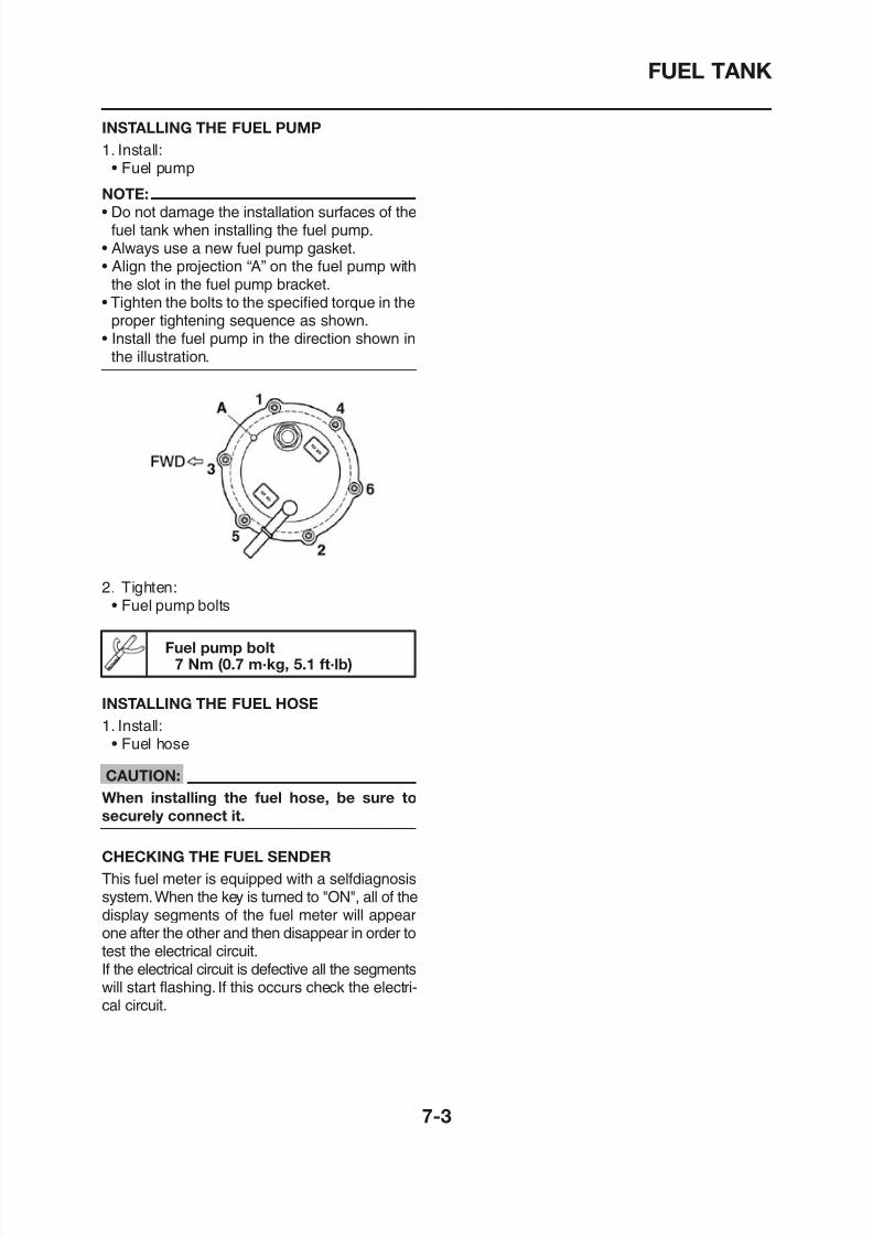
8/12/2019 Yamaha Tenere XT660Z Service Manual
http://slidepdf.com/reader/full/yamaha-tenere-xt660z-service-manual 287/398
fuel tank when installing the fuel pump.• Always use a new fuel pump gasket.• Align the projection “A” on the fuel pump with
the slot in the fuel pump bracket.• Tighten the bolts to the specified torque in the
proper tightening sequence as shown.• Install the fuel pump in the direction shown in
the illustration.
2. Tighten:• Fuel pump bolts
Fuel pump bolt
THROTTLE BODY ASSEMBLY
Removing the throttle body assembly
THROTTLE BODY ASSEMBLY
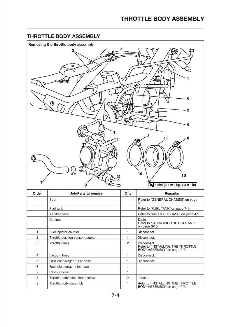
8/12/2019 Yamaha Tenere XT660Z Service Manual
http://slidepdf.com/reader/full/yamaha-tenere-xt660z-service-manual 288/398
THROTTLE BODY ASSEMBLY
Removing the throttle body assembly
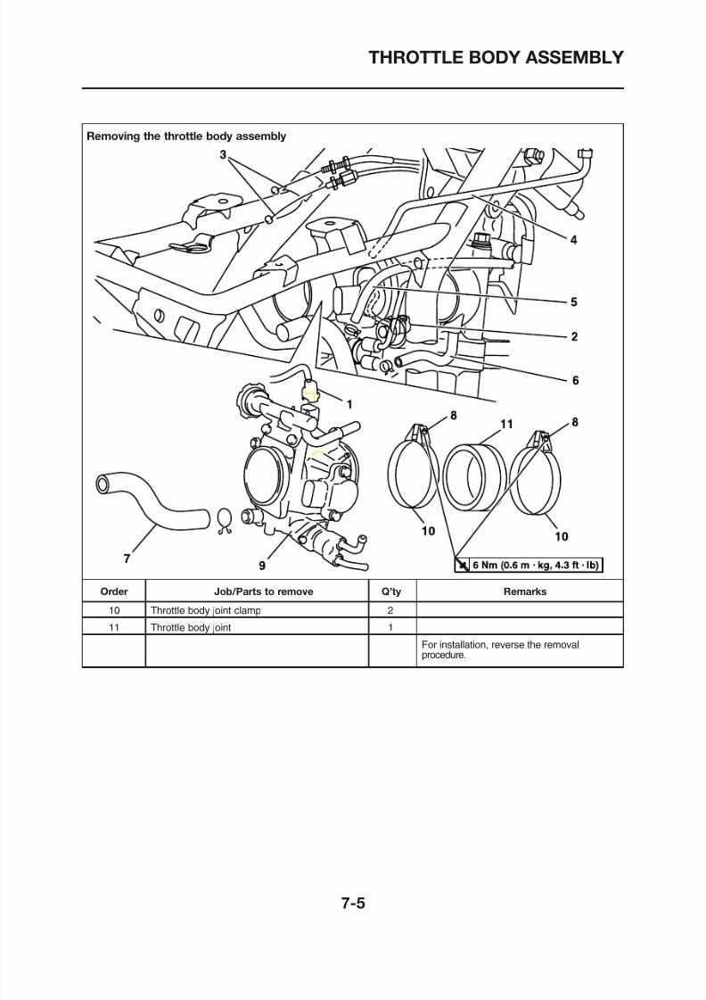
8/12/2019 Yamaha Tenere XT660Z Service Manual
http://slidepdf.com/reader/full/yamaha-tenere-xt660z-service-manual 289/398
THROTTLE BODY ASSEMBLY
Disassembling the throttle body assembly
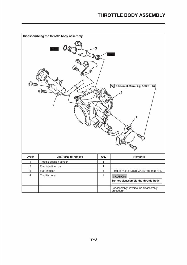
8/12/2019 Yamaha Tenere XT660Z Service Manual
http://slidepdf.com/reader/full/yamaha-tenere-xt660z-service-manual 290/398
THROTTLE BODY ASSEMBLY
EAS00912
CHECKING THE FUEL INJECTOR
1. Check:• Fuel injector
Damage→
Replace.2. Check:• Fuel injector resistance
INSTALLING THE THROTTLE BODY
ASSEMBLY
1 Install:
b. Blow out all of the passages with com-pressed air.
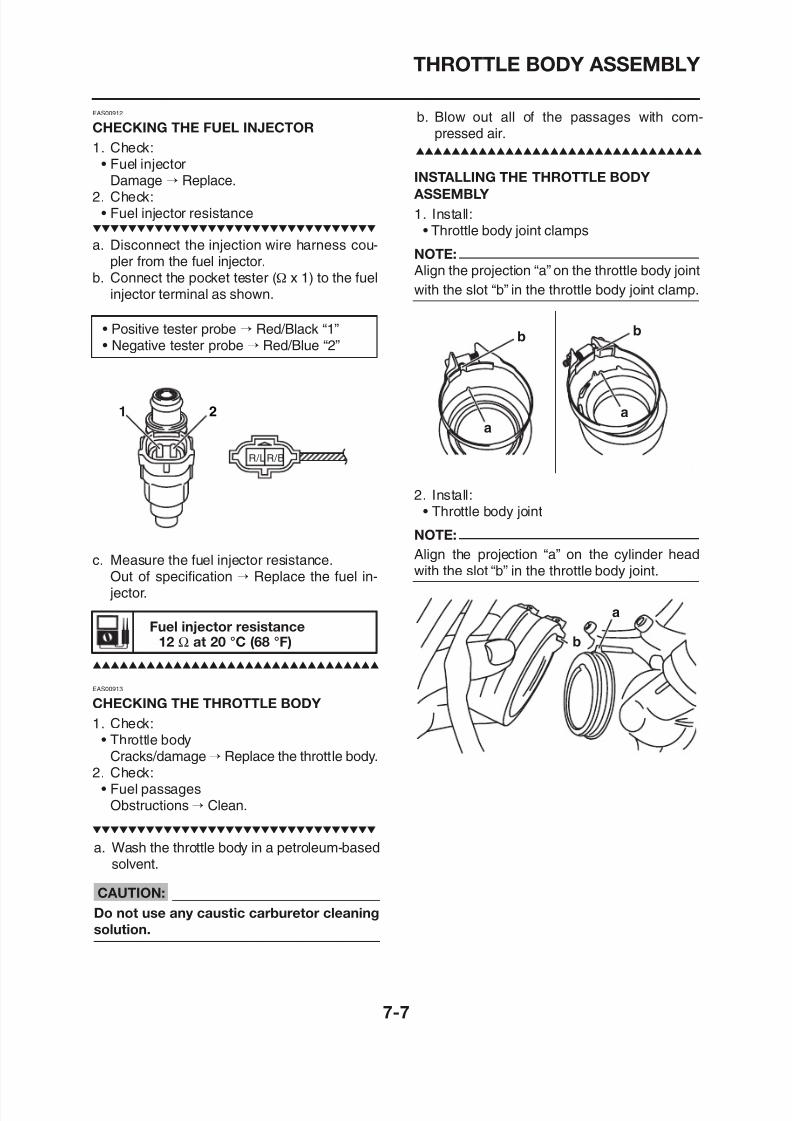
8/12/2019 Yamaha Tenere XT660Z Service Manual
http://slidepdf.com/reader/full/yamaha-tenere-xt660z-service-manual 291/398
Fuel injector resistance
a. Disconnect the injection wire harness cou-pler from the fuel injector.
b. Connect the pocket tester (Ω x 1) to the fuelinjector terminal as shown.
• Positive tester probe → Red/Black “1”• Negative tester probe → Red/Blue “2”
c. Measure the fuel injector resistance.Out of specification → Replace the fuel in-jector
R/LR/B
1 2
1. Install:• Throttle body joint clamps
NOTE:
Align the projection “a” on the throttle body joint
with the slot “b” in the throttle body joint clamp.
2. Install:• Throttle body joint
NOTE:
Align the projection “a” on the cylinder headwith the slot “b” in the throttle body joint.
a
a
b b
THROTTLE BODY ASSEMBLY
3. Install:• Throttle body assembly
NOTE:
Align the projection “a” on the throttle body as-
sembly with the slot “b” throttle body joint.
a. Fill the fuel tank.b. Put the end of the fuel hose into an open
container.
c. Connect a battery (DC 12 V) to the fuelpump coupler as shown.
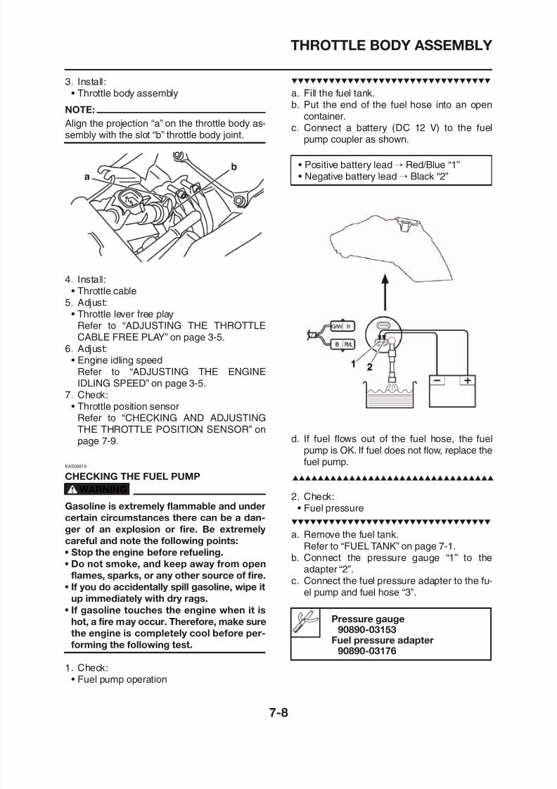
8/12/2019 Yamaha Tenere XT660Z Service Manual
http://slidepdf.com/reader/full/yamaha-tenere-xt660z-service-manual 292/398
4. Install:• Throttle cable
5. Adjust:• Throttle lever free play
Refer to “ADJUSTING THE THROTTLECABLE FREE PLAY” on page 3-5.
6. Adjust:• Engine idling speed
Refer to “ADJUSTING THE ENGINEIDLING SPEED” on page 3-5.
7. Check:• Throttle position sensor
Refer to “CHECKING AND ADJUSTING
a
b • Positive battery lead → Red/Blue “1”• Negative battery lead → Black “2”
THROTTLE BODY ASSEMBLY
d. Connect the fuel pump coupler “4” and fuelsender coupler “5” to the fuel pump.Refer to “FUEL TANK” on page 7-1.
2 1
• Tester positive lead → blue “1”• Tester negative lead → black/blue “2”
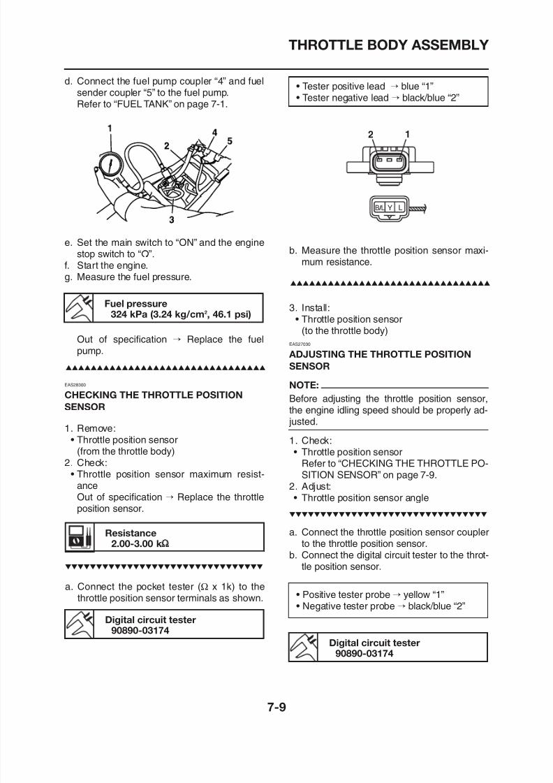
8/12/2019 Yamaha Tenere XT660Z Service Manual
http://slidepdf.com/reader/full/yamaha-tenere-xt660z-service-manual 293/398
e. Set the main switch to “ON” and the enginestop switch to “I”.
f. Start the engine.g. Measure the fuel pressure.
Out of specification → Replace the fuelpump.
Fuel pressure324 kPa (3.24 kg/cm2, 46.1 psi)
EAS28300
CHECKING THE THROTTLE POSITION
SENSOR
b. Measure the throttle position sensor maxi-mum resistance.
3. Install:
• Throttle position sensor(to the throttle body)
EAS27030
ADJUSTING THE THROTTLE POSITION
SENSOR
NOTE:
Before adjusting the throttle position sensor,the engine idling speed should be properly ad-
LYB / L
THROTTLE BODY ASSEMBLY
Output voltage (at idle)0 63 0 73 V
c. Turn the main switch to “ON”.d. Measure the throttle position sensor voltage.e. Adjust the throttle position sensor angle so
that the voltage is within the specified range.
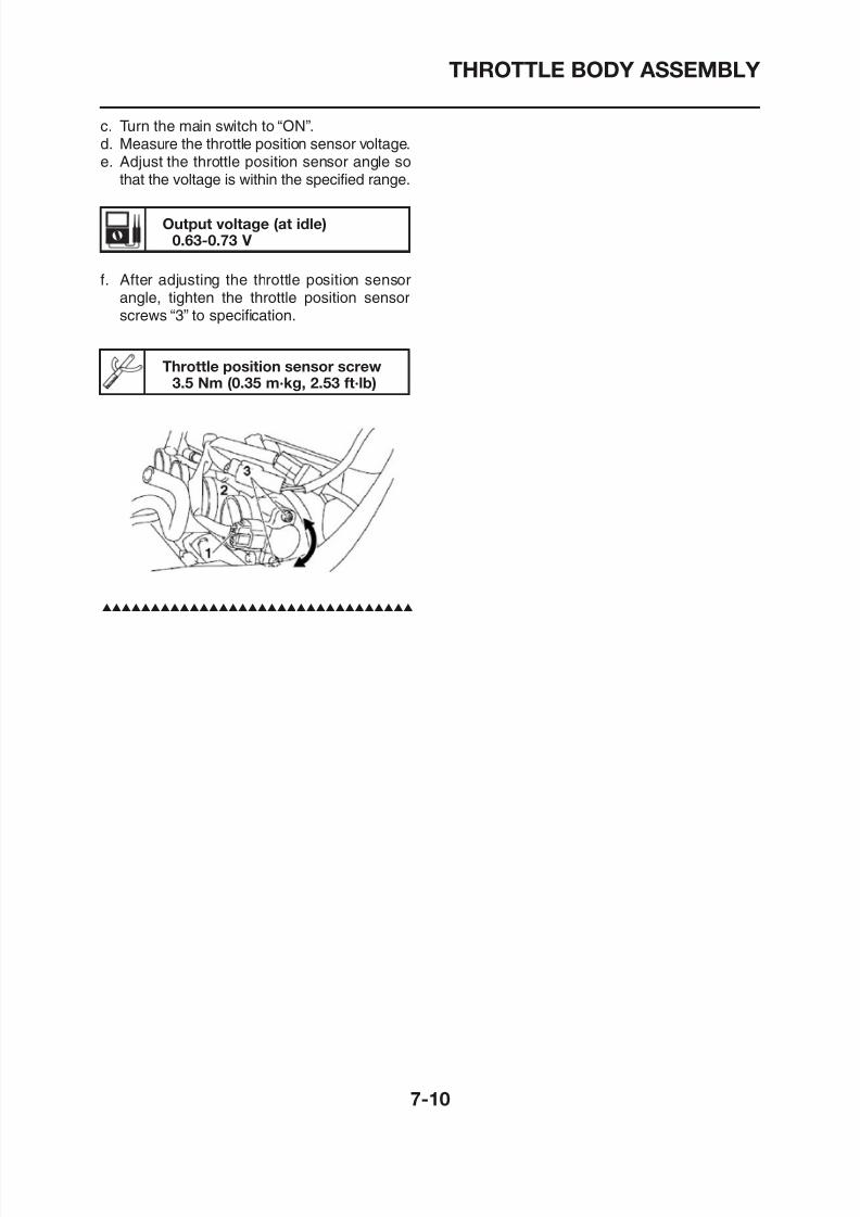
8/12/2019 Yamaha Tenere XT660Z Service Manual
http://slidepdf.com/reader/full/yamaha-tenere-xt660z-service-manual 294/398
Throttle position sensor screw3.5 Nm (0.35 m·kg, 2.53 ft·lb)
f. After adjusting the throttle position sensorangle, tighten the throttle position sensorscrews “3” to specification.
0.63-0.73 V
AIR INDUCTION SYSTEM
AIR INDUCTION SYSTEM
EAS00507
AIR INJECTION
The air induction system burns unburned ex-
haust gases by injecting fresh air (secondaryair) into the exhaust port, reducing the emission
EAS00917
AIR CUT-OFF VALVE
The air cut-off valve is controlled by the signalsfrom the ECU in accordance with the combus-tion conditions. Ordinarily, the air cut-off valveopens to allow the air to flow during idle andcloses to cut-off the flow when the vehicle is be-
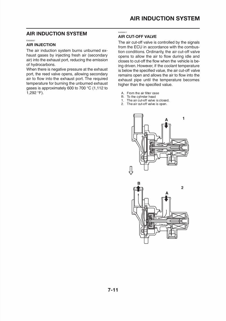
8/12/2019 Yamaha Tenere XT660Z Service Manual
http://slidepdf.com/reader/full/yamaha-tenere-xt660z-service-manual 295/398
of hydrocarbons.When there is negative pressure at the exhaustport, the reed valve opens, allowing secondaryair to flow into the exhaust port. The requiredtemperature for burning the unburned exhaustgases is approximately 600 to 700 °C (1,112 to
1,292 °F).
ing driven. However, if the coolant temperatureis below the specified value, the air cut-off valveremains open and allows the air to flow into theexhaust pipe until the temperature becomeshigher than the specified value.
A. From the air filter caseB. To the cylinder head1. The air cut-off valve is closed.2. The air cut-off valve is open.
1A
AIR INDUCTION SYSTEM
EAS00509
AIR INDUCTION SYSTEM DIAGRAMS
1. Air filter case2. Reed valve3. Air cut-off valve4. Exhaust port
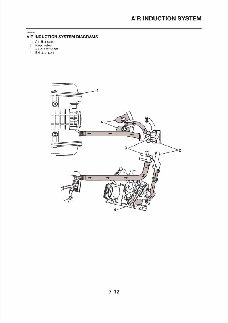
8/12/2019 Yamaha Tenere XT660Z Service Manual
http://slidepdf.com/reader/full/yamaha-tenere-xt660z-service-manual 296/398
AIR INDUCTION SYSTEM
Removing the air cut-off valve assembly
AIR CUT-OFF VALVE ASSEMBLY
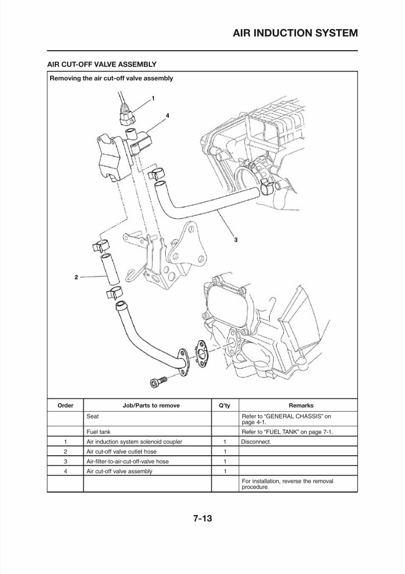
8/12/2019 Yamaha Tenere XT660Z Service Manual
http://slidepdf.com/reader/full/yamaha-tenere-xt660z-service-manual 297/398
AIR INDUCTION SYSTEM
Disassembling the air cut-off valve assembly
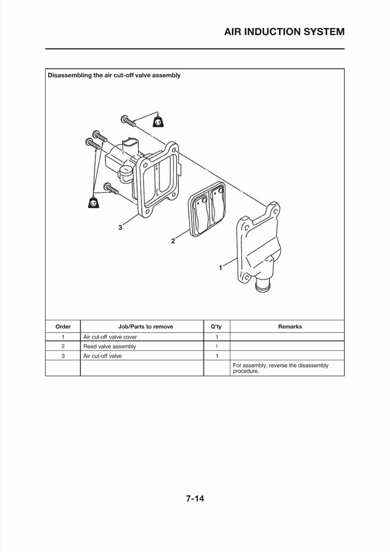
8/12/2019 Yamaha Tenere XT660Z Service Manual
http://slidepdf.com/reader/full/yamaha-tenere-xt660z-service-manual 298/398
LT
LT
3
2
1
AIR INDUCTION SYSTEM
EAS00918
CHECKING THE AIR INDUCTION SYSTEM
1. Check:• Hoses
Loose connections → Connect properly.Cracks/damage → Replace.
• Pipe
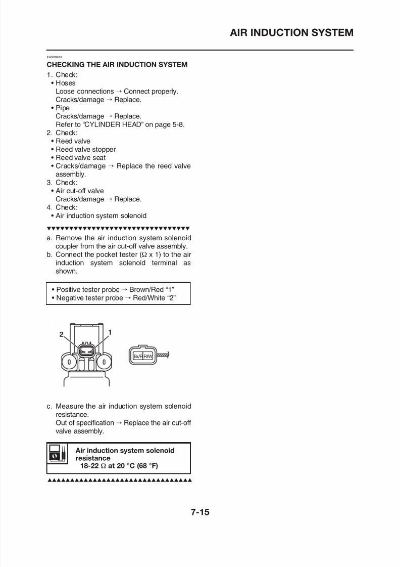
8/12/2019 Yamaha Tenere XT660Z Service Manual
http://slidepdf.com/reader/full/yamaha-tenere-xt660z-service-manual 299/398
Cracks/damage → Replace.Refer to “CYLINDER HEAD” on page 5-8.
2. Check:• Reed valve• Reed valve stopper• Reed valve seat
• Cracks/damage → Replace the reed valveassembly.
3. Check:• Air cut-off valve
Cracks/damage → Replace.4. Check:
• Air induction system solenoid
a. Remove the air induction system solenoidcoupler from the air cut-off valve assembly.
b. Connect the pocket tester (Ω x 1) to the airinduction system solenoid terminal asshown.
• Positive tester probe → Brown/Red “1”• Negative tester probe → Red/White “2”
FUEL INJECTION SYSTEM
EAS00895
FUEL INJECTION SYSTEM
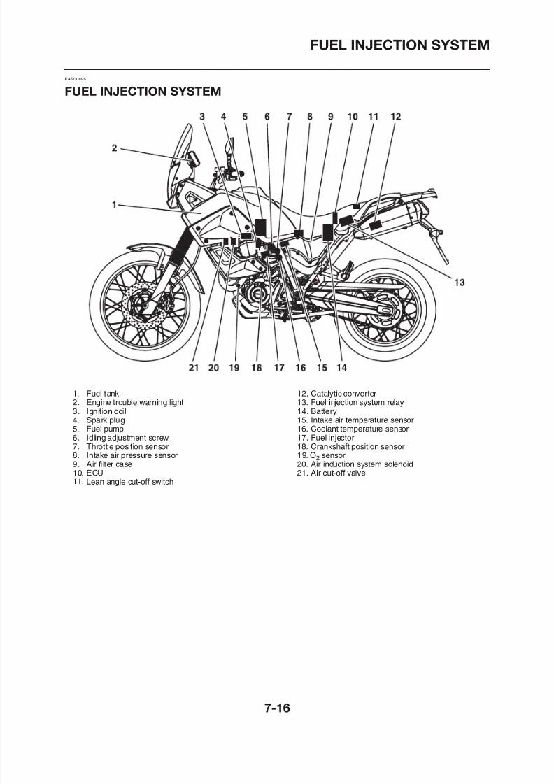
8/12/2019 Yamaha Tenere XT660Z Service Manual
http://slidepdf.com/reader/full/yamaha-tenere-xt660z-service-manual 300/398
1. Fuel tank2. Engine trouble warning light3. Ignition coil
12. Catalytic converter13. Fuel injection system relay14. Battery
FUEL INJECTION SYSTEM
WIRING DIAGRAM
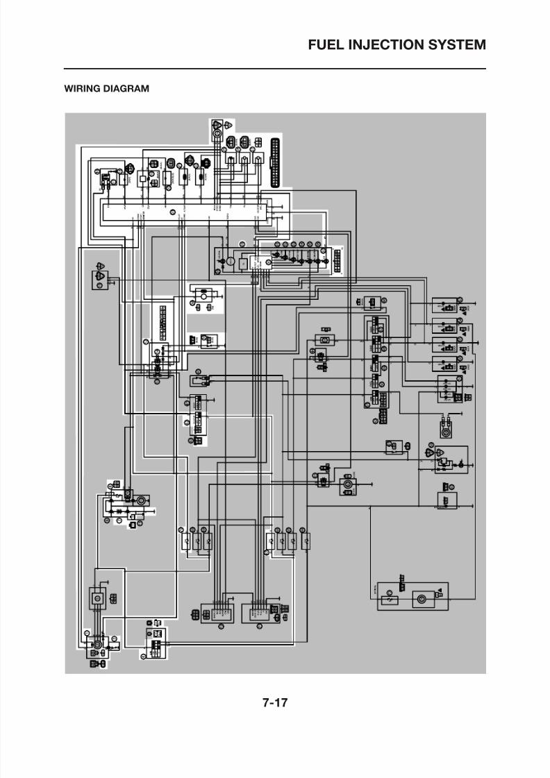
8/12/2019 Yamaha Tenere XT660Z Service Manual
http://slidepdf.com/reader/full/yamaha-tenere-xt660z-service-manual 301/398
FUEL INJECTION SYSTEM
1. Crankshaft position sensor3. Neutral switch4. Main switch7. Battery8. Main fuse12. Relay unit
14. Fuel injection system relay16. Ignition coil17. Spark plug18 F l i j
8/12/2019 Yamaha Tenere XT660Z Service Manual
http://slidepdf.com/reader/full/yamaha-tenere-xt660z-service-manual 302/398
18. Fuel injector19. O2 sensor20. Air induction system solenoid21. Intake air temperature sensor22. Coolant temperature sensor23. ECU24. Speed sensor25. Throttle position sensor
26. Intake air pressure sensor27. Lean angle cut-off switch28. Multi-function meter unit37. Engine trouble warning light38. Fuel pump39. Sidestand switch42. Engine stop switch67. Ignition fuse70. Fuel injection system fuse
FUEL INJECTION SYSTEM
ECU’S SELF-DIAGNOSTIC FUNCTION
The ECU is equipped with a self-diagnosticfunction in order to ensure that the engine con-trol system is operating normally. If this function
detects a malfunction in the system, it immedi-ately operates the engine under substitutecharacteristics and illuminates the engine trou-
• To inform the rider that the fuel injection sys-tem is not functioning correctly, the enginetrouble warning light flashes when the startswitch is being pushed to start the engine.
• If a malfunction is detected in the system bythe self-diagnostic function, this mode pro-vides an appropriate substitute characteristic
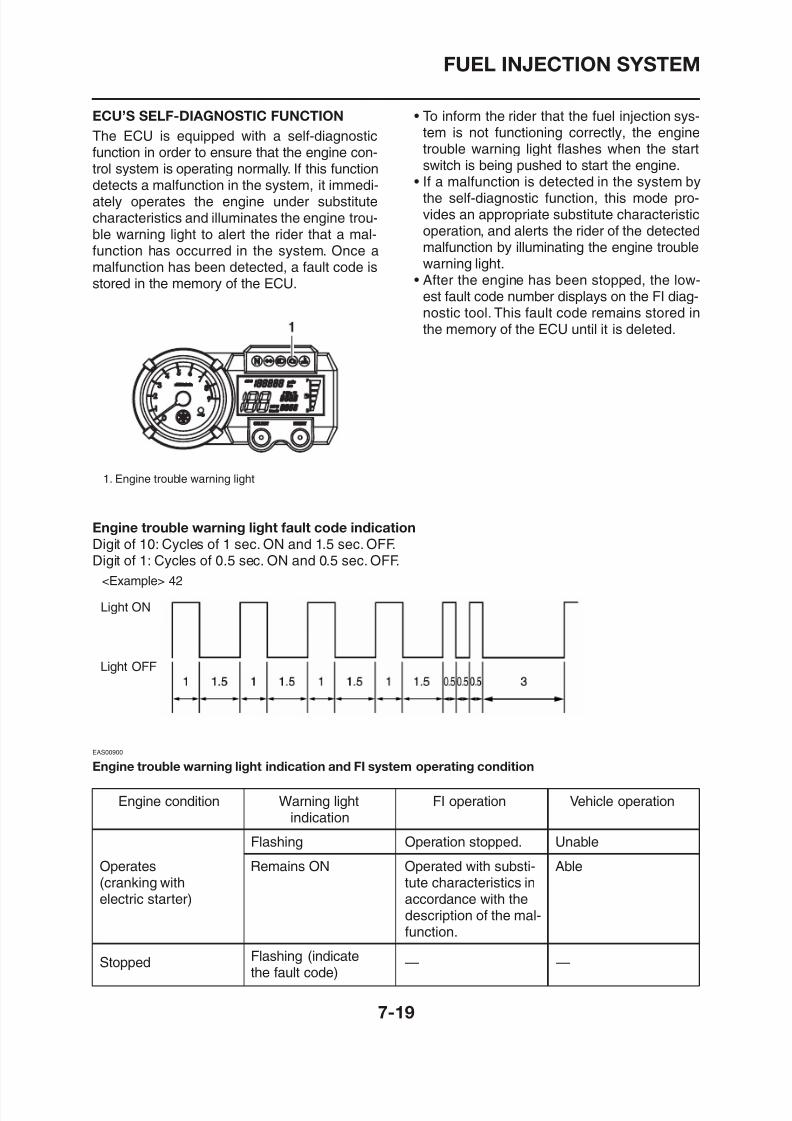
8/12/2019 Yamaha Tenere XT660Z Service Manual
http://slidepdf.com/reader/full/yamaha-tenere-xt660z-service-manual 303/398
gble warning light to alert the rider that a mal-function has occurred in the system. Once amalfunction has been detected, a fault code isstored in the memory of the ECU.
1. Engine trouble warning light
operation, and alerts the rider of the detectedmalfunction by illuminating the engine troublewarning light.
• After the engine has been stopped, the low-est fault code number displays on the FI diag-nostic tool. This fault code remains stored in
the memory of the ECU until it is deleted.
Engine trouble warning light fault code indication
Digit of 10: Cycles of 1 sec. ON and 1.5 sec. OFF.Digit of 1: Cycles of 0.5 sec. ON and 0.5 sec. OFF.
<Example> 42
FUEL INJECTION SYSTEM
EAS27380
SELF-DIAGNOSTIC FUNCTION TABLE
If the ECU detects an abnormal signal from a sensor while the vehicle is being driven, the ECU illu-minates the engine trouble warning light and provides the engine with alternate operating instruc-tions that are appropriate for the type of malfunction.When an abnormal signal is received from a sensor, the ECU processes the specified values that areprogrammed for each sensor in order to provide the engine with alternate operating instructions that
bl th i t ti t t t ti d di th diti
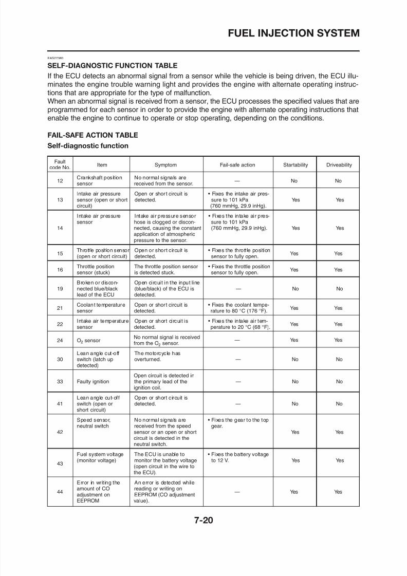
8/12/2019 Yamaha Tenere XT660Z Service Manual
http://slidepdf.com/reader/full/yamaha-tenere-xt660z-service-manual 304/398
enable the engine to continue to operate or stop operating, depending on the conditions.
FAIL-SAFE ACTION TABLE
Self-diagnostic function
FaultItem Symptom Fail-safe action Startability Driveability
code No.
12Crankshaft position No normal signals are
— No Nosensor received from the sensor.
Intake air pressure Open or shor t circuit is • Fixes the intake air pres-13 sensor (open or short detected. sure to 101 kPa Yes Yes
circuit) (760 mmHg, 29.9 inHg).
Intake air pressure Intake air pressure sensor • Fixes the intake air pres-sensor hose is clogged or discon- sure to 101 kPa
14 nected, causing the constant (760 mmHg, 29.9 inHg). Yes Yesapplication of atmospheric
pressure to the sensor.
15Throttle position sensor Open or short circuit is • Fixes the throttle position
Yes Yes(open or short circuit) detected. sensor to fully open.
16Throttle position The throttle position sensor • Fixes the throttle position
Yes Yessensor (stuck) is detected stuck. sensor to fully open.
Broken or discon- Open circuit in the input line19 nected blue/black (blue/black) of the ECU is — No No
lead of the ECU detected.
Coolant temperature Open or short circuit is • Fixes the coolant tempe-
FUEL INJECTION SYSTEM
FaultItem Symptom Fail-safe action Startability Driveability
code No.
Vehicle system Power supply to the fuel46 power supply injection system relay is not — Yes Yes
(monitor voltage) normal.
ECU internal Faulty ECU memory.When
50malfunction this malfunction is detected,
— No Yes(memory check error) the code number might not
appear on the meter
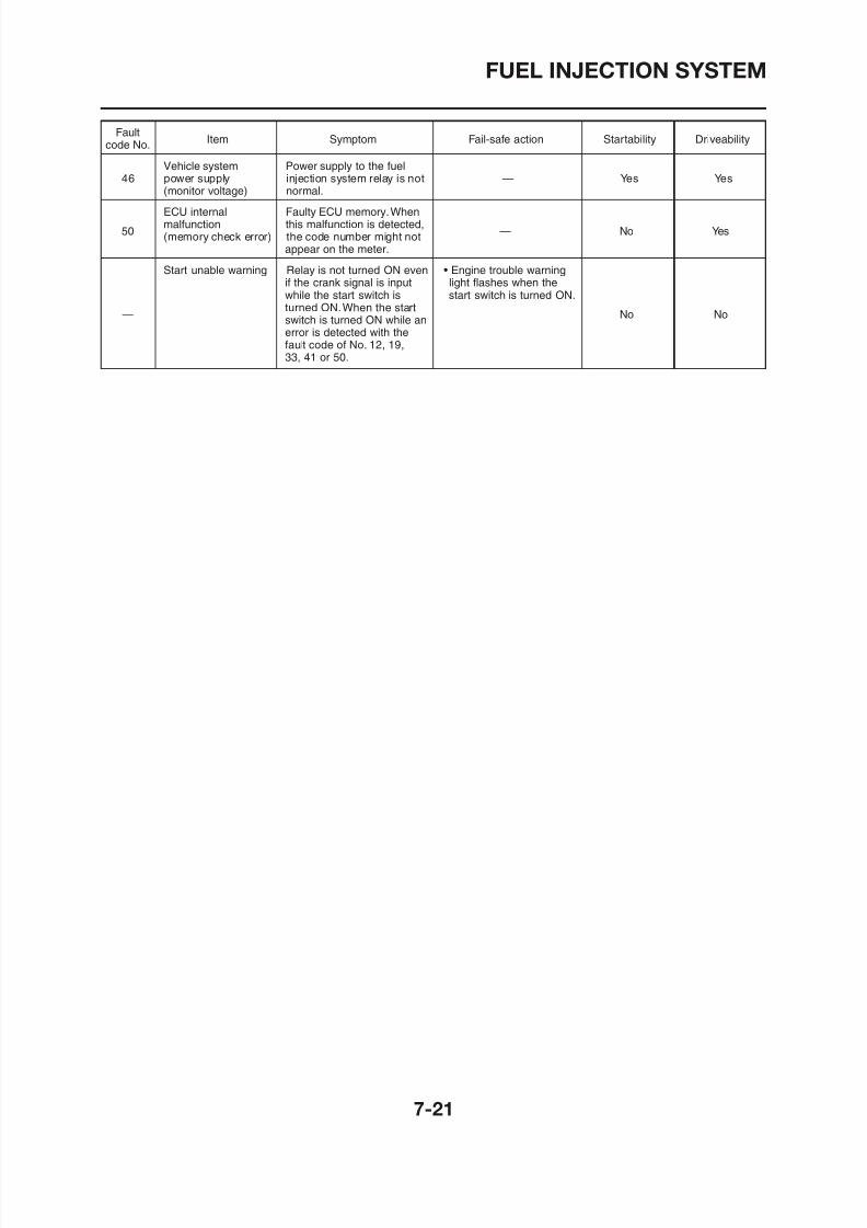
8/12/2019 Yamaha Tenere XT660Z Service Manual
http://slidepdf.com/reader/full/yamaha-tenere-xt660z-service-manual 305/398
appear on the meter.
Start unable warning Relay is not turned ON even • Engine trouble warningif the crank signal is input light flashes when thewhile the start switch is start switch is turned ON.
—turned ON.When the start
No Noswitch is turned ON while anerror is detected with thefault code of No. 12, 19,
33, 41 or 50.
FUEL INJECTION SYSTEM
EAS00904
TROUBLESHOOTING CHART
Engine operation is not normal or the engine trouble warning light is on.* Engine trouble warning light may not come on even if the engine operation is not normal.
The engine trouble warning light comes on. The engine trouble warning light does not come on.
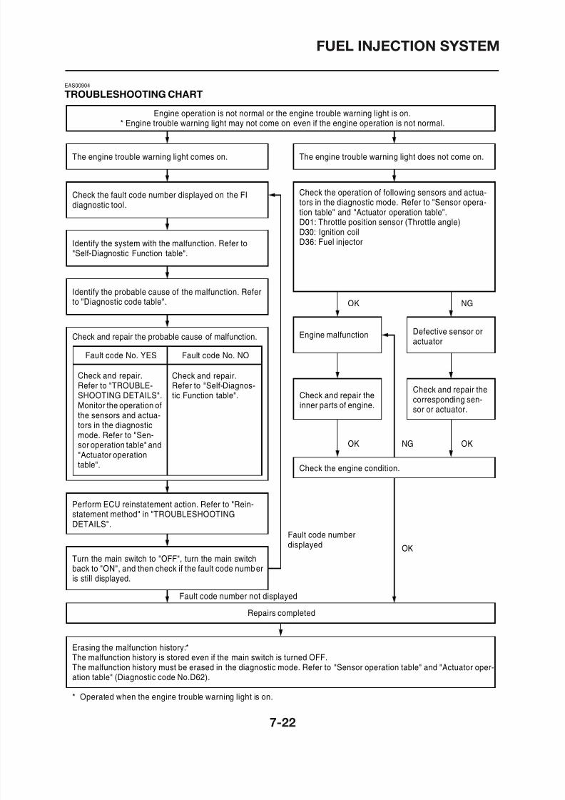
8/12/2019 Yamaha Tenere XT660Z Service Manual
http://slidepdf.com/reader/full/yamaha-tenere-xt660z-service-manual 306/398
Check the fault code number displayed on the FIdiagnostic tool.
Identify the system with the malfunction. Refer to"Self-Diagnostic Function table".
Identify the probable cause of the malfunction. Referto "Diagnostic code table".
Check and repair the probable cause of malfunction.
Fault code No. YES Fault code No. NO
Check and repair.Refer to "TROUBLE-SHOOTING DETAILS".Monitor the operation ofthe sensors and actua-tors in the diagnostic
Check and repair.Refer to "Self-Diagnos-tic Function table".
Check the operation of following sensors and actua-tors in the diagnostic mode. Refer to "Sensor opera-tion table" and "Actuator operation table".D01: Throttle position sensor (Throttle angle)
D30: Ignition coilD36: Fuel injector
Engine malfunction Defective sensor oractuator
Check and repair theinner parts of engine.
Check and repair thecorresponding sen-sor or actuator.
OK NG
FUEL INJECTION SYSTEM
HAS00905
DIAGNOSTIC MODE
It is possible to monitor the sensor output dataor check the activation of actuators with the FIdiagnostic tool connected to the vehicle and setto the normal mode or the diagnostic monitor-ing mode.
FI Diagnostic Tool
1600rpm 35ßC
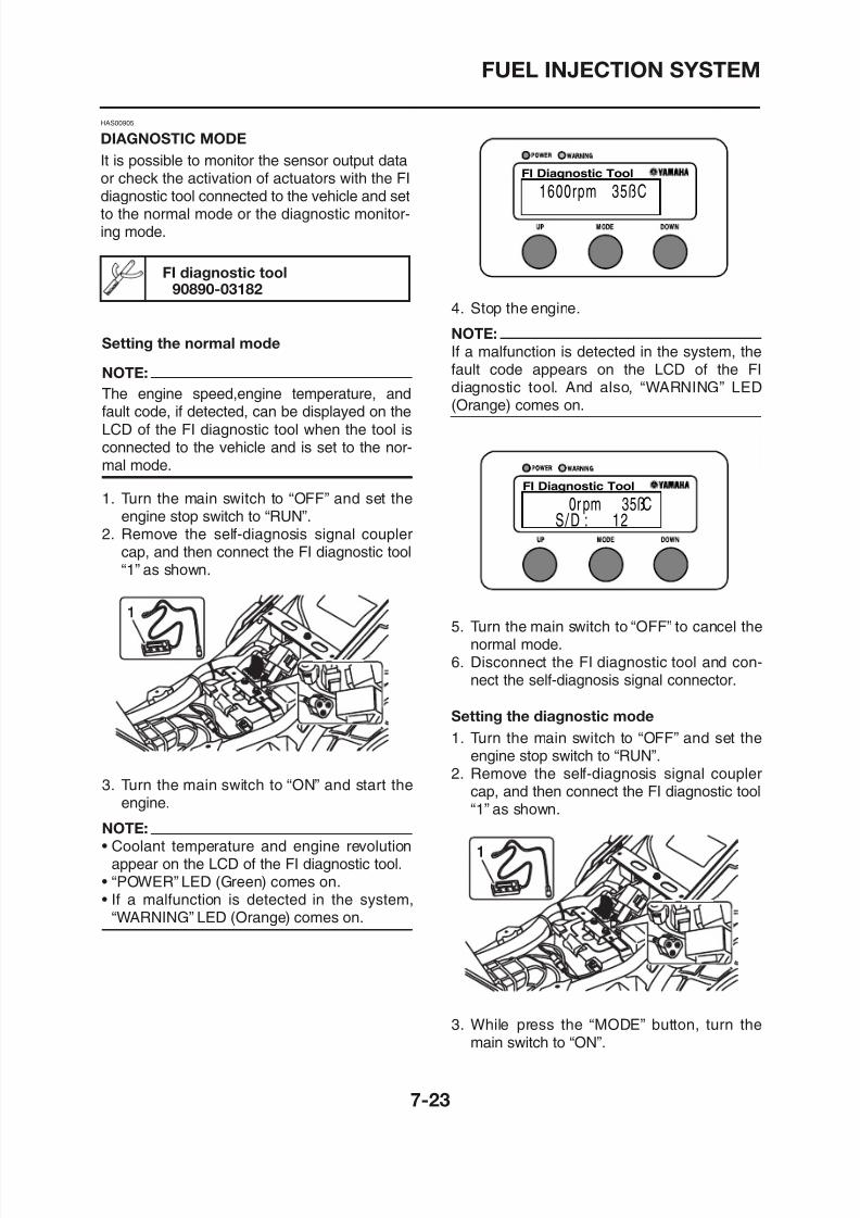
8/12/2019 Yamaha Tenere XT660Z Service Manual
http://slidepdf.com/reader/full/yamaha-tenere-xt660z-service-manual 307/398
FI diagnostic tool90890-03182
Setting the normal mode
NOTE:
The engine speed,engine temperature, andfault code, if detected, can be displayed on theLCD of the FI diagnostic tool when the tool isconnected to the vehicle and is set to the nor-mal mode.
1. Turn the main switch to “OFF” and set theengine stop switch to “RUN”.
2. Remove the self-diagnosis signal couplercap, and then connect the FI diagnostic tool“1” as shown.
4. Stop the engine.
NOTE:
If a malfunction is detected in the system, thefault code appears on the LCD of the FIdiagnostic tool. And also, “WARNING” LED(Orange) comes on.
5. Turn the main switch to “OFF” to cancel thenormal mode
FI Diagnostic Tool
0r pm 35ßCS / D : 12
FUEL INJECTION SYSTEM
NOTE:
• “DIAG” appears on the LCD of the FI diag-nostic tool.
• “POWER” LED (Green) comes on.
4. Press the “UP” button to select the CO ad- justment mode “CO” or the diagnostic mode“DIAG”
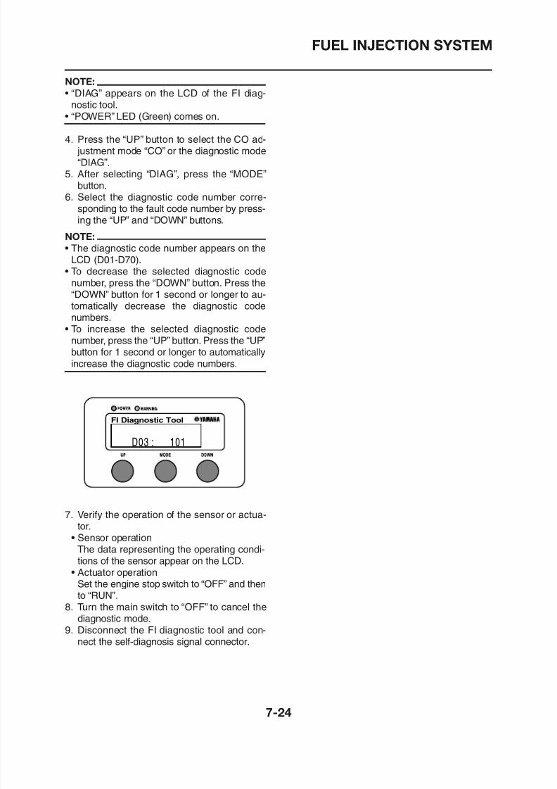
8/12/2019 Yamaha Tenere XT660Z Service Manual
http://slidepdf.com/reader/full/yamaha-tenere-xt660z-service-manual 308/398
DIAG”.5. After selecting “DIAG”, press the “MODE”
button.6. Select the diagnostic code number corre-
sponding to the fault code number by press-ing the “UP” and “DOWN” buttons.
NOTE:
• The diagnostic code number appears on theLCD (D01-D70).
• To decrease the selected diagnostic codenumber, press the “DOWN” button. Press the“DOWN” button for 1 second or longer to au-tomatically decrease the diagnostic codenumbers.
• To increase the selected diagnostic codenumber, press the “UP” button. Press the “UP”button for 1 second or longer to automaticallyincrease the diagnostic code numbers.
FI Di ti T l
FUEL INJECTION SYSTEM
EAS00906
Diagnostic monitoring code table
FaultSymptom Probable cause of malfunction Diagnostic code
code No.
No normal signals are received from • Open or short circuit in wire harnessthe crankshaft position sensor. • Defective crankshaft position sensor
• Disconnected crankshaft position sensor coupler _
• Malfunction in A C magneto rotor12
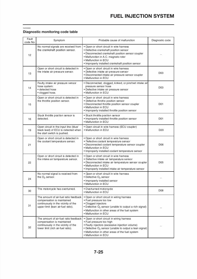
8/12/2019 Yamaha Tenere XT660Z Service Manual
http://slidepdf.com/reader/full/yamaha-tenere-xt660z-service-manual 309/398
Malfunction in A.C. magneto rotor
• Malfunction in ECU
• Improperly installed crankshaft position sensor
Open or short circuit is detected in • Open or short circuit in wire harness
the intake air pressure sensor. • Defective intake air pressure sensor D03• Disconnected intake air pressure sensor coupler• Malfunction in ECU
Faulty intake air pressure sensor • Disconnected, clogged, kinked, or pinched intake air
hose system: pressure sensor hose D03• detected hose • Defective intake air pressure sensor
• clogged hose. • Malfunction in ECU
Open or short circuit is detected in • Open or short circuit in wire harness
the throttle position sensor. • Defective throttle position sensor
• Disconnected throttle position sensor coupler D01
• Malfunction in ECU• Improperly installed throttle position sensor
Stuck throttle position sensor is • Stuck throttle position sensordetected. • Improperly installed throttle position sensor D01
• Malfunction in ECU
Open circuit in the input line (blue/ • Open circuit in wire harness (ECU coupler)
black lead) of ECU is detected when • Malfunction in ECU D20
the start switch is pushed.
Open or short circuit is detected in • Open or short circuit in wire harnessthe coolant temperature sensor. • Defective coolant temperature sensor
• Disconnected coolant temperature sensor coupler D06
• Malfunction in ECU
13
14
15
16
19
21
FUEL INJECTION SYSTEM
FaultSymptom Probable cause of malfunction Diagnostic code
code No.
Open circuit is detected in the • Open circuit in wire harness
primary lead of the ignition coil. • Malfunction in ignition coil• Malfunction in ECU D30
• Malfunction in a component of the ignition cut-offcircuit system
Open or short circuit is detected in • Open or short circuit in wire harness
33
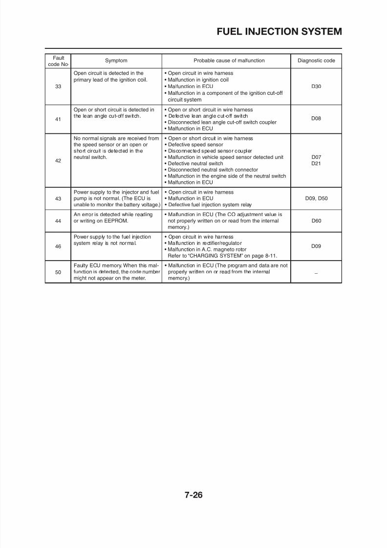
8/12/2019 Yamaha Tenere XT660Z Service Manual
http://slidepdf.com/reader/full/yamaha-tenere-xt660z-service-manual 310/398
the lean angle cut-off switch. • Defective lean angle cut-off switch D08• Disconnected lean angle cut-off switch coupler
• Malfunction in ECU
No normal signals are received from • Open or short circuit in wire harnessthe speed sensor or an open or • Defective speed sensor
short circuit is detected in the • Disconnected speed sensor coupler
neutral switch. • Malfunction in vehicle speed sensor detected unit D07
• Defective neutral switch D21• Disconnected neutral switch connector
• Malfunction in the engine side of the neutral switch
• Malfunction in ECU
Power supply to the injector and fuel • Open circuit in wire harnesspump is not normal. (The ECU is • Malfunction in ECU D09, D50
unable to monitor the battery voltage.) • Defective fuel injection system relay
An error is detected while reading • Malfunction in ECU (The CO adjustment value is
or writing on EEPROM. not properly written on or read from the internal D60
memory.)Power supply to the fuel injection • Open circuit in wire harness
system relay is not normal. • Malfunct ion in rectifier/regulatorD09
• Malfunction in A.C. magneto rotor
Refer to “CHARGING SYSTEM” on page 8-11.
Faulty ECU memory. When this mal- • Malfunction in ECU (The program and data are not
function is detected, the code number properly written on or read from the internal _
might not appear on the meter. memory.)
41
42
43
44
46
50
FUEL INJECTION SYSTEM
EAS00907
Diagnostic mode table
Switch the meter display from the regular mode to the diagnostic mode. To switch the display, referto “DIAGNOSTIC MODE”.
NOTE:• Check the intake air temperature and coolant temperature as close as possible to the intake air tem-
perature sensor and the coolant temperature sensor respectively.f f
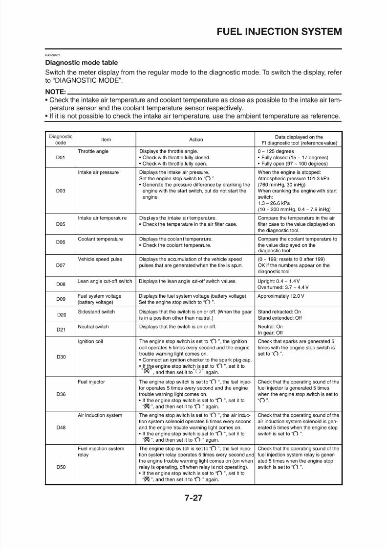
8/12/2019 Yamaha Tenere XT660Z Service Manual
http://slidepdf.com/reader/full/yamaha-tenere-xt660z-service-manual 311/398
D08Lean angle cut-off switch Displays the lean angle cut-off switch values. Upright: 0.4 ~ 1.4 V
Overturned: 3.7 ~ 4.4 V
Diagnostic
codeItem Action
D01
Throttle angle Displays the throttle angle.
• Check with throttle fully closed.
• Check with throttle fully open.
0 ~ 125 degrees
• Fully closed (15 ~ 17 degrees)
• Fully open (97 ~ 100 degrees)
D03
Intake air pressure Displays the intake air pressure.
Set the engine stop switch to “ ”.
• Generate the pressure difference by cranking the
engine with the start switch, but do not start the
engine.
When the engine is stopped:
Atmospheric pressure 101.3 kPa
(760 mmHg, 30 inHg)
When cranking the engine with start
switch:
1.3 ~ 26.6 kPa
(10 ~ 200 mmHg, 0.4 ~ 7.9 inHg)
D05
Intake air temperature Displays the intake air temperature.
• Check the temperature in the air filter case.
Compare the temperature in the air
filter case to the value displayed on
the diagnostic tool.
D06Coolant temperature Displays the coolant temperature.
• Check the coolant temperature.
Compare the coolant temperature to
the value displayed on the
D07
Vehicle speed pulse Displays the accumulation of the vehicle speed
pulses that are generated when the tire is spun.
(0 ~ 199; resets to 0 after 199)
OK if the numbers appear on the
diagnostic tool.
Data displayed on theFI diagnostic tool (reference value)
diagnostic tool.
• If it is not possible to check the intake air temperature, use the ambient temperature as reference.
FUEL INJECTION SYSTEM
D51
Radiator fan motor relay The engine stop switch is set to “ “, the radiator
fan motor relay operates 5 times, 5 seconds each
time (2 seconds on, 3 seconds off), and the engine
trouble warning light comes on.
• If the engine stop switch is set to “ ”, set it to
“ ”, and then set it to “ ” again.
Check that the operating sound of the
radiator fan motor relay is generated
and that the radiator fan motor is
operated 5 times when the engine
stop switch is set to “ ”.
Diagnostic
codeItem Action
Data displayed on theFI diagnostic tool (reference value)
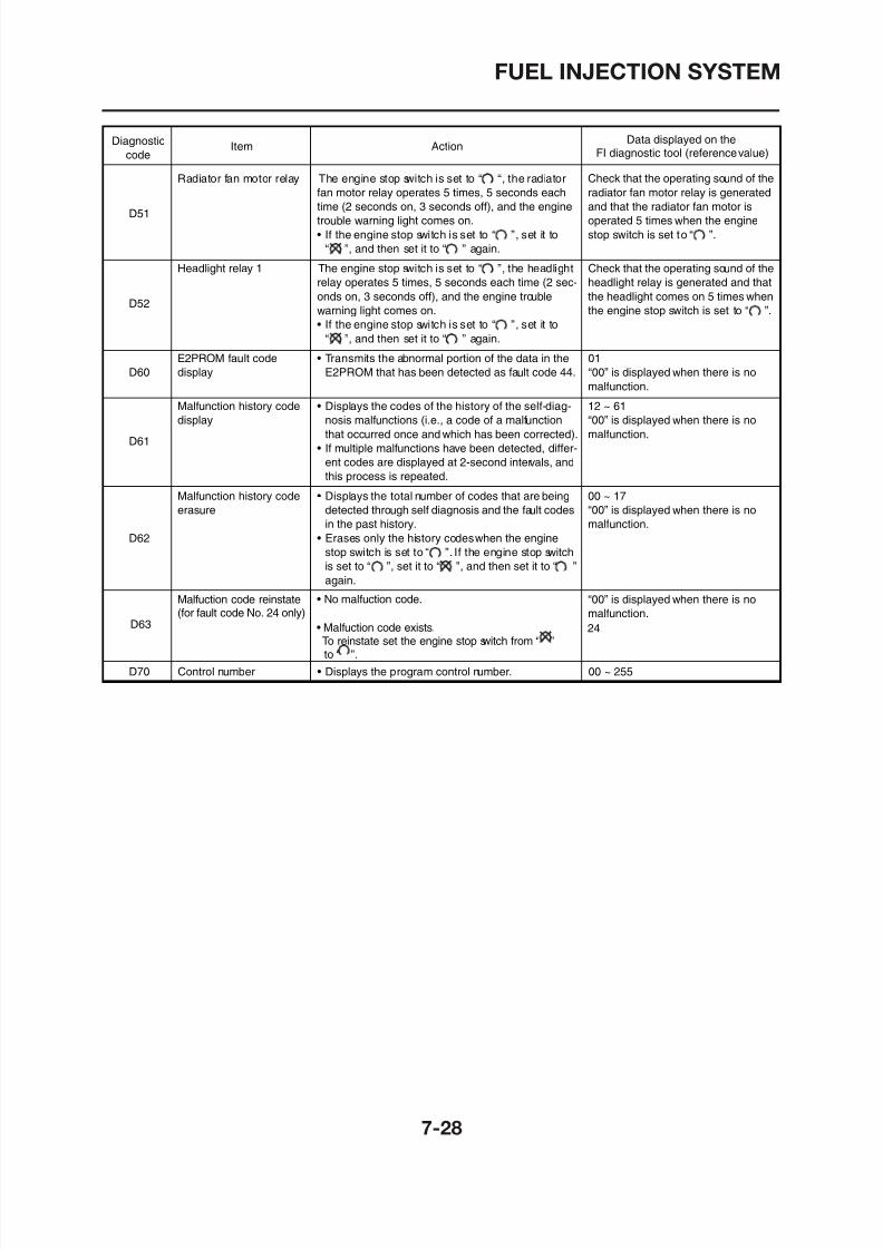
8/12/2019 Yamaha Tenere XT660Z Service Manual
http://slidepdf.com/reader/full/yamaha-tenere-xt660z-service-manual 312/398
D52
Headlight relay 1 The engine stop switch is set to “ ”, the headlight
relay operates 5 times, 5 seconds each time (2 sec-
onds on, 3 seconds off), and the engine trouble
warning light comes on.
• If the engine stop switch is set to “ ”, set it to
“ ”, and then set it to “ ” again.
Check that the operating sound of the
headlight relay is generated and that
the headlight comes on 5 times when
the engine stop switch is set to “ ”.
D60
E2PROM fault code
display
• Transmits the abnormal portion of the data in the
E2PROM that has been detected as fault code 44.
01
“00” is displayed when there is no
malfunction.
D61
Malfunction history code
display
• Displays the codes of the history of the self-diag-
nosis malfunctions (i.e., a code of a malfunction
that occurred once and which has been corrected).
• If multiple malfunctions have been detected, differ-
ent codes are displayed at 2-second intervals, and
this process is repeated.
12 ~ 61
“00” is displayed when there is no
malfunction.
D62
Malfunction history code
erasure
• Displays the total number of codes that are being
detected through self diagnosis and the fault codes
in the past history.• Erases only the history codes when the engine
stop switch is set to “ ”. If the engine stop switch
is set to “ ”, set it to “ ”, and then set it to “ ”
again.
00 ~ 17
“00” is displayed when there is no
malfunction.
D63
Malfuction code reinstate(for fault code No. 24 only)
• No malfuction code. “00” is displayed when there is no
malfunction.
24• Malfuction code exists. To reinstate set the engine stop switch from “ ”
to “ ”.
FUEL INJECTION SYSTEM
TROUBLESHOOTING DETAILS
This section describes the countermeasures per fault code number displayed on the FI diagnostictool. Check and service the items or components that are the probable cause of the malfunction fol-lowing the order given.
After the check and service of the malfunctioning part has been completed, reset the FI diagnostictool display according to the “Reinstatement method”.Fault code No.:
Fault code number displayed on the FI diagnostic tool when the engine failed to work normally
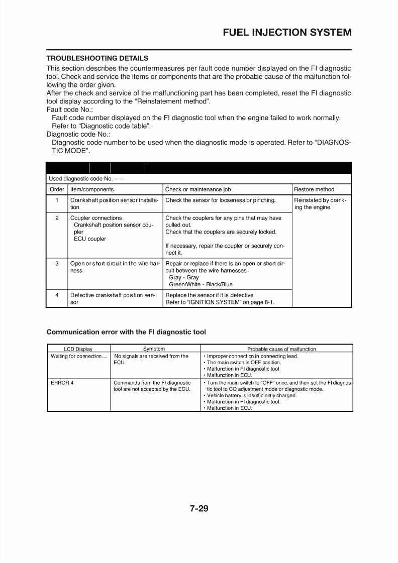
8/12/2019 Yamaha Tenere XT660Z Service Manual
http://slidepdf.com/reader/full/yamaha-tenere-xt660z-service-manual 313/398
Fault code number displayed on the FI diagnostic tool when the engine failed to work normally.Refer to “Diagnostic code table”.
Diagnostic code No.:Diagnostic code number to be used when the diagnostic mode is operated. Refer to “DIAGNOS-TIC MODE”.
Fault code No. 12 Symptom No normal signals are received from the crankshaft position sensor.
Used diagnostic code No. – –
Order Item/components Check or maintenance job Restore method
1 Crankshaft position sensor installa-
tion
Check the sensor for looseness or pinching. Reinstated by crank-
ing the engine.
2 Coupler connections
Crankshaft position sensor cou-
pler
ECU coupler
Check the couplers for any pins that may have
pulled out.
Check that the couplers are securely locked.
If necessary, repair the coupler or securely con-
nect it.
3 Open or short circuit in the wire har-
ness
Repair or replace if there is an open or short cir-
cuit between the wire harnesses.
Gray - Gray
Green/White - Black/Blue
4 Defective crankshaft position sen- Replace the sensor if it is defective.
FUEL INJECTION SYSTEM
Fault code No. 13 Symptom Open or short circuit is detected from the intake air pressure sensor.
Used diagnostic code No. 03 (intake air pressure sensor)
Order Item/components Check or maintenance job Restore method
1 Coupler connectionsIntake air pressure sensor coupler
ECU coupler
Sub-wire harness coupler
Check the couplers for any pins that may havepulled out.
Check that the couplers are securely locked.
Reinstated by crank-ing the engine.
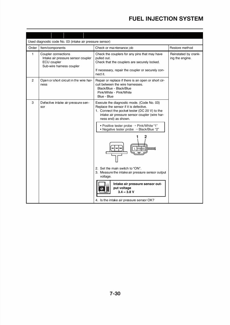
8/12/2019 Yamaha Tenere XT660Z Service Manual
http://slidepdf.com/reader/full/yamaha-tenere-xt660z-service-manual 314/398
p
If necessary, repair the coupler or securely con-
nect it.
2 Open or short circuit in the wire har-
ness
Repair or replace if there is an open or short cir-
cuit between the wire harnesses.
Black/Blue - Black/Blue
Pink/White - Pink/White
Blue - Blue
3 Defective intake air pressure sen-
sor
Execute the diagnostic mode. (Code No. 03)
Replace the sensor if it is defective.
1. Connect the pocket tester (DC 20 V) to the
intake air pressure sensor coupler (wire har-
ness end) as shown.
2. Set the main switch to “ON”.
3 Measure the intake air pressure sensor output
L B / LP / W
1 2
• Positive tester probe → Pink/White “1”• Negative tester probe → Black/Blue “2”
FUEL INJECTION SYSTEM
Fault code No. 14 Symptom Intake air pressure sensor hose is disconnected or clogged.
Used diagnostic code No. 03 (intake air pressure sensor)
Order Item/components Check or maintenance job Restore method
1 Disconnected, clogged, kinked, orpinched intake air pressure sensor
hose
Repair or replace the hose. Reinstated by start-ing the engine and
operating it at idle.
Intake air pressure sensor malfunc Check and repair the connection
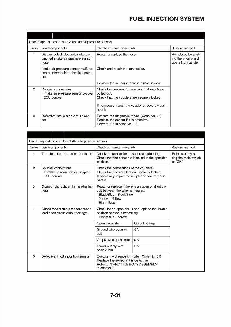
8/12/2019 Yamaha Tenere XT660Z Service Manual
http://slidepdf.com/reader/full/yamaha-tenere-xt660z-service-manual 315/398
Intake air pressure sensor malfunc-
tion at intermediate electrical poten-
tial
Check and repair the connection.
Replace the sensor if there is a malfunction.
2 Coupler connections
Intake air pressure sensor coupler
ECU coupler
Check the couplers for any pins that may have
pulled out.
Check that the couplers are securely locked.
If necessary, repair the coupler or securely con-
nect it.
3 Defective intake air pressure sen-
sor
Execute the diagnostic mode. (Code No. 03)
Replace the sensor if it is defective.
Refer to “Fault code No. 13”.
Fault code No. 15 Symptom Open or short circuit is detected from the throttle position senor.Used diagnostic code No. 01 (throttle position sensor)
Order Item/components Check or maintenance job Restore method
1 Throttle position sensor installation Check the sensor for looseness or pinching.
Check that the sensor is installed in the specified
position.
Reinstated by set-
ting the main switch
to “ON”.
2 Coupler connections
Throttle position sensor coupler
Check the connections of the couplers.
Check that the couplers are securely locked.
FUEL INJECTION SYSTEM
Fault code No. 16 Symptom The throttle position sensor is detected stuck.
Used diagnostic code No. 01 (throttle position sensor)
Order Item/components Check or maintenance job Restore method
1 Defective throttle position sensor Replace the sensor if it is defective.Refer to “THROTTLE BODY ASSEMBLY”. Reinstated by start-ing the engine, oper-
ating it at idle, and
then racing it.2 Throttle position sensor installation Execute the diagnostic mode. (Code No. 01)
Ch k th f l i hi
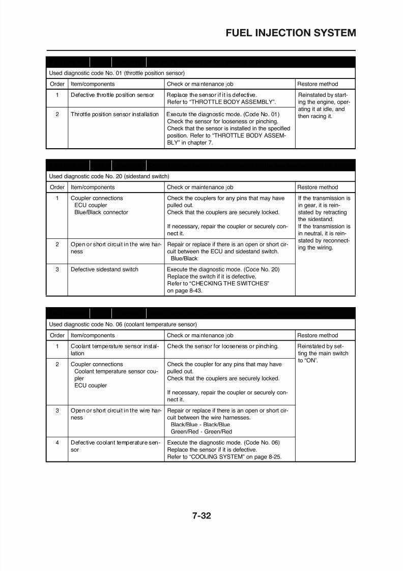
8/12/2019 Yamaha Tenere XT660Z Service Manual
http://slidepdf.com/reader/full/yamaha-tenere-xt660z-service-manual 316/398
Check the sensor for looseness or pinching.
Check that the sensor is installed in the specified
position. Refer to “THROTTLE BODY ASSEM-
BLY” in chapter 7.
Fault code No. 19 Symptom Open circuit is detected in the input wire from the sidestand switch to the ECU.Used diagnostic code No. 20 (sidestand switch)
Order Item/components Check or maintenance job Restore method
1 Coupler connections
ECU coupler
Blue/Black connector
Check the couplers for any pins that may have
pulled out.
Check that the couplers are securely locked.
If necessary, repair the coupler or securely con-
nect it.
If the transmission is
in gear, it is rein-
stated by retracting
the sidestand.
If the transmission is
in neutral, it is rein-
stated by reconnect-ing the wiring.
2 Open or short circuit in the wire har-
ness
Repair or replace if there is an open or short cir-
cuit between the ECU and sidestand switch.
Blue/Black
3 Defective sidestand switch Execute the diagnostic mode. (Code No. 20)
Replace the switch if it is defective.
Refer to “CHECKING THE SWITCHES”
on page 8-43.
FUEL INJECTION SYSTEM
Fault code No. 22 Symptom Open or short circuit is detected from the intake air temperature sensor.
Used diagnostic code No. 05 (intake air temperature sensor)
Order Item/components Check or maintenance job Restore method
1 Intake air temperature sensorinstallation Check the sensor looseness or pinching. Reinstated by set-ting the main switch
to “ON”.2 Coupler connections
Intake air temperature sensor cou
Check the couplers for any pins that may have
pulled out
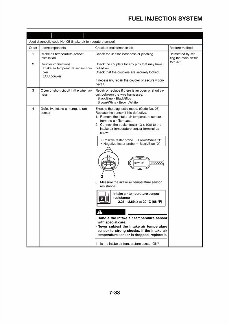
8/12/2019 Yamaha Tenere XT660Z Service Manual
http://slidepdf.com/reader/full/yamaha-tenere-xt660z-service-manual 317/398
Intake air temperature sensor cou-
pler
ECU coupler
pulled out.
Check that the couplers are securely locked.
If necessary, repair the coupler or securely con-
nect it.
3 Open or short circuit in the wire har-
ness
Repair or replace if there is an open or short cir-
cuit between the wire harnesses.Black/Blue - Black/Blue
Brown/White - Brown/White
4 Defective intake air temperature
sensor
Execute the diagnostic mode. (Code No. 05)
Replace the sensor if it is defective.
1. Remove the intake air temperature sensor
from the air filter case.
2. Connect the pocket tester to the
intake air temperature sensor terminal as
shown.
Br / W B / L
(Ω x 100)
• Positive tester probe → Brown/White “1”• Negative tester probe → Black/Blue “2”
FUEL INJECTION SYSTEM
Used diagnostic code No. – –
Order Item/components Check or maintenance job Restore method
1 Installed condition of O2 sensor. Check the installed area for looseness or pinching. Starting the engine,warming it up until
the coolanttemperature is 60 °C
2 Connected state of connector Check the coupler for any pins that may haveO2 sensor coupler pulled out.ECU coupler Check the locking condition of the coupler
Fault code No. 24 Symptom No normal signal is received from the O2 sensor.
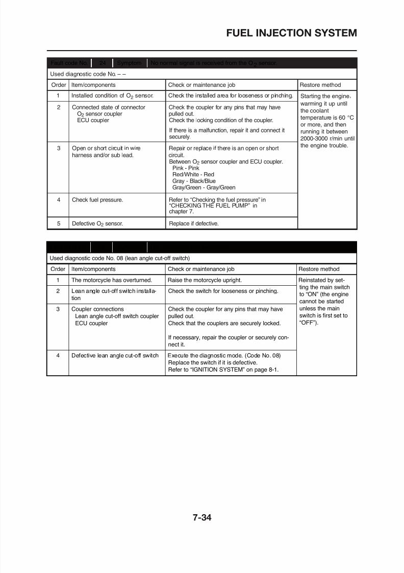
8/12/2019 Yamaha Tenere XT660Z Service Manual
http://slidepdf.com/reader/full/yamaha-tenere-xt660z-service-manual 318/398
Fault code No. 30 Symptom The motorcycle has overturned.
Used diagnostic code No. 08 (lean angle cut-off switch)
Order Item/components Check or maintenance job Restore method
1 The motorcycle has overturned. Raise the motorcycle upright. Reinstated by set-
ting the main switch
to “ON” (the engine
cannot be started
2 Lean angle cut-off switch installa-
tion
Check the switch for looseness or pinching.
or more, and thenrunning it between2000-3000 r/min untilthe engine trouble.
indicator turns off.
ECU coupler Check the locking condition of the coupler.
If there is a malfunction, repair it and connect itsecurely.
3 Open or short circuit in wire Repair or replace if there is an open or shortharness and/or sub lead. circuit.
Between O2 sensor coupler and ECU coupler.
Pink - PinkRed/White - RedGray - Black/BlueGray/Green - Gray/Green
4 Check fuel pressure. Refer to “Checking the fuel pressure” in“CHECKING THE FUEL PUMP” inchapter 7.
5 Defective O2 sensor. Replace if defective.
FUEL INJECTION SYSTEM
Fault code No. 33 Symptom Malfunction detected in the primary lead of the ignition coil.
Used diagnostic code No. 30 (ignition coil)
Order Item/components Check or maintenance job Restore method
1 Coupler and connector connections
Ignition coil primary connector
(Orange)
ECU coupler
Check the coupler and connector for any pins
that may have pulled out.
Check the connector and coupler are securely
locked.
Reinstated by start-
ing the engine and
operating it at idle.
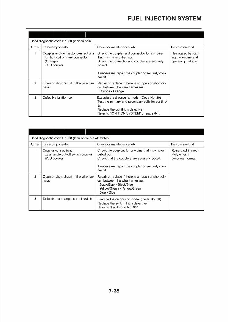
8/12/2019 Yamaha Tenere XT660Z Service Manual
http://slidepdf.com/reader/full/yamaha-tenere-xt660z-service-manual 319/398
If necessary, repair the coupler or securely con-
nect it.
2 Open or short circuit in the wire har-
ness
Repair or replace if there is an open or short cir-
cuit between the wire harnesses.
Orange - Orange
3 Defective ignition coil Execute the diagnostic mode. (Code No. 30)
Test the primary and secondary coils for continu-
ity.
Replace the coil if it is defective.
Refer to “IGNITION SYSTEM” on page 8-1.
Fault code No. 41 Symptom Open or short circuit is detected in the lean angle cut-off switch.
Used diagnostic code No. 08 (lean angle cut-off switch)
Order Item/components Check or maintenance job Restore method
1 Coupler connections
Lean angle cut-off switch coupler
ECU coupler
Check the couplers for any pins that may have
pulled out.
Check that the couplers are securely locked.
If necessary, repair the coupler or securely con-
nect it
Reinstated immedi-
ately when it
becomes normal.
FUEL INJECTION SYSTEM
Fault code No. 42 Symptom A. No normal signals are received from the speed sensor.
B. Open or short circuit is detected in the neutral switch.
Used diagnostic code No. 07 (speed sensor) A1 ~ A4 / No. 21 (neutral switch) B1 ~ B4
Order Item/components Check or maintenance job Restore method
A-1 Coupler connections
Speed sensor coupler
ECU coupler
Check the couplers for any pins that may have
pulled out.
Check that the couplers are securely locked.
Reinstated by starting
the engine, and input-
ting the vehicle speed
signals b operating
→ →
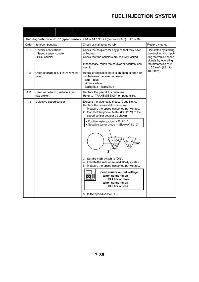
8/12/2019 Yamaha Tenere XT660Z Service Manual
http://slidepdf.com/reader/full/yamaha-tenere-xt660z-service-manual 320/398
If necessary, repair the coupler or securely con-
nect it.
signals by operating
the motorcycle at 20
to 30 km/h (12.4 to
18.6 mi/h).A-2 Open or short circuit in the wire har-
ness
Repair or replace if there is an open or short cir-
cuit between the wire harnesses.
Blue - Blue
White - WhiteBlack/Blue - Black/Blue
A-3 Gear for detecting vehicle speed
has broken.
Replace the gear if it is defective.
Refer to “TRANSMISSION” on page 5-69.
A-4 Defective speed sensor Execute the diagnostic mode. (Code No. 07)
Replace the sensor if it is defective.
1. Measure the speed sensor output voltage.
2. Connect the pocket tester (DC 20 V) to the
speed sensor coupler as shown.
P O / R
B / W
L W
B / L
1
• Positive tester probe → Pink “1”• Negative tester probe → Black/White “2”
FUEL INJECTION SYSTEM
B-1 Coupler connections
Neutral switch connector
Wiring harness ECU coupler
Check the couplers for any pins that may have
pulled out.
Check that the couplers are securely locked.
Reinstated by starting
the engine, and input-
ting the vehicle speed
i l b ti
Fault code No. 42 Symptom A. No normal signals are received from the speed sensor.
B. Open or short circuit is detected in the neutral switch.
Used diagnostic code No. 07 (speed sensor) A1 ~ A4 / No. 21 (neutral switch) B1 ~ B4
Order Item/components Check or maintenance job Restore method
→ →
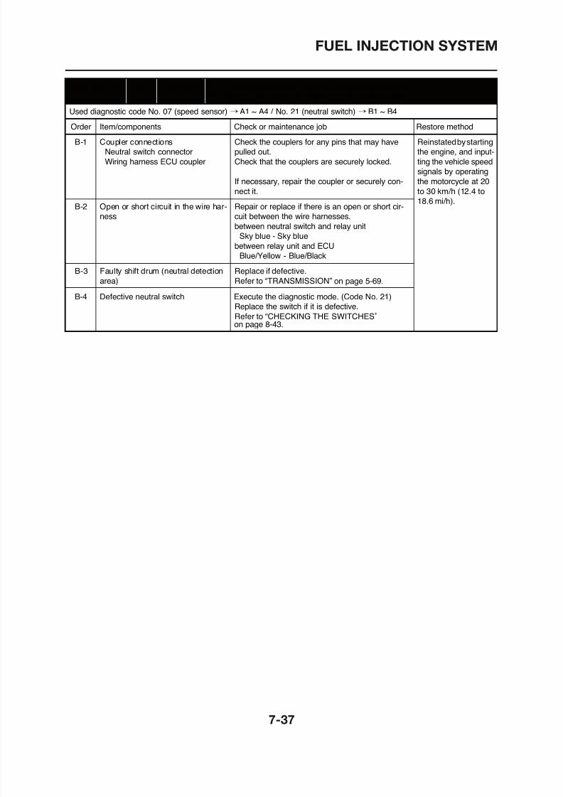
8/12/2019 Yamaha Tenere XT660Z Service Manual
http://slidepdf.com/reader/full/yamaha-tenere-xt660z-service-manual 321/398
If necessary, repair the coupler or securely con-
nect it.
signals by operating
the motorcycle at 20
to 30 km/h (12.4 to
18.6 mi/h).B-2 Open or short circuit in the wire har-
ness
Repair or replace if there is an open or short cir-
cuit between the wire harnesses.
between neutral switch and relay unit
Sky blue - Sky bluebetween relay unit and ECU
Blue/Yellow - Blue/Black
B-3 Faulty shift drum (neutral detection
area)
Replace if defective.
Refer to “TRANSMISSION”
B-4 Defective neutral switch Execute the diagnostic mode. (Code No. 21)
Replace the switch if it is defective.
Refer to “CHECKING THE SWITCHES”on page 8-43.
on page 5-69.
FUEL INJECTION SYSTEM
Fault code No. 43 Symptom The ECU is unable to monitor the battery voltage.
Used diagnostic code No. 09, 50 (fuel system voltage)
Order Item/components Check or maintenance job Restore method
1 Coupler connections
Fuel injection system relay cou-
pler
Wiring harness ECU coupler
Check the couplers for any pins that may have
pulled out.
Check that the couplers are securely locked.
If necessary repair the coupler or securely con
Reinstated by start-
ing the engine and
operating it at idle.
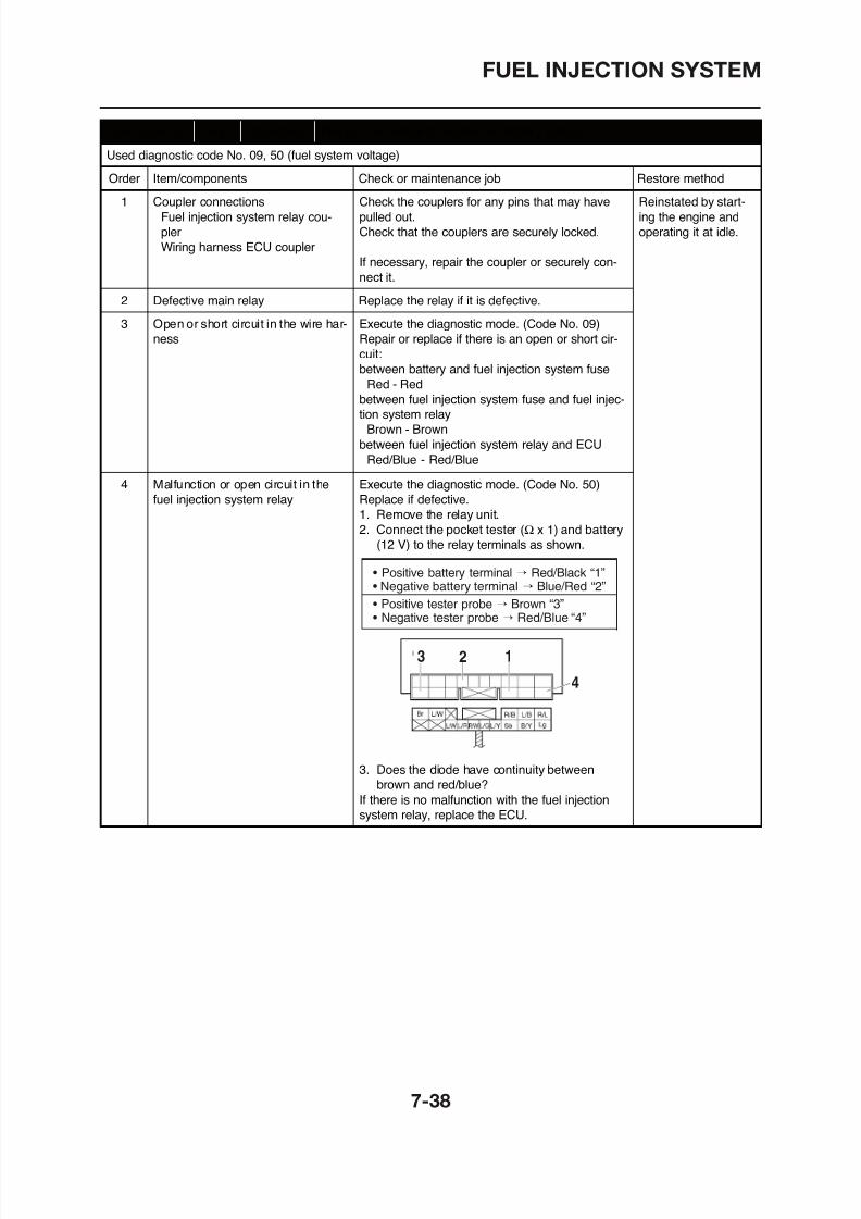
8/12/2019 Yamaha Tenere XT660Z Service Manual
http://slidepdf.com/reader/full/yamaha-tenere-xt660z-service-manual 322/398
If necessary, repair the coupler or securely con-
nect it.
2 Defective main relay Replace the relay if it is defective.
3 Open or short circuit in the wire har-
ness
Execute the diagnostic mode. (Code No. 09)
Repair or replace if there is an open or short cir-
cuit:between battery and fuel injection system fuse
Red - Red
between fuel injection system fuse and fuel injec-
tion system relay
Brown - Brown
between fuel injection system relay and ECU
Red/Blue - Red/Blue
4 Malfunction or open circuit in the
fuel injection system relay
Execute the diagnostic mode. (Code No. 50)
Replace if defective.
1. Remove the relay unit.2. Connect the pocket tester and battery
(12 V) to the relay terminals as shown.(Ω x 1)
• Positive battery terminal → Red/Black “1”• Negative battery terminal → Blue/Red “2”
• Positive tester probe → Brown “3”• Negative tester probe → Red/Blue “4”
Fault code No. 44 Symptom Error is detected while reading or writing on EEPROM
(CO adjustment value).
Used diagnostic code No. 60 (EEPROM improper cylinder indication)
Order Item/components Check or maintenance job Restore method
1 Malfunction in ECU Execute the diagnostic mode. (Code No. 60)
• Check the faulty cylinder.
• Readjust the CO of the displayed cylinder.
R l th ECU if it i d f ti
Reinstated by set-
ting the main switch
to “ON”.
FUEL INJECTION SYSTEM
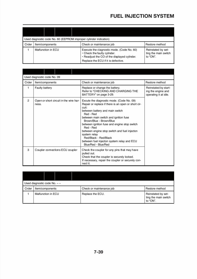
8/12/2019 Yamaha Tenere XT660Z Service Manual
http://slidepdf.com/reader/full/yamaha-tenere-xt660z-service-manual 323/398
Replace the ECU if it is defective.
Fault code No. 46 Symptom Power supply to the FI system relay is not normal.
Used diagnostic code No. 09
Order Item/components Check or maintenance job Restore method
1 Faulty battery Replace or change the battery.
Refer to “CHECKING AND CHARGING THE
BATTERY”
Reinstated by start-
ing the engine and
operating it at idle.
2 Open or short circuit in the wire har-
ness.
Excute the diagnostic mode. (Code No. 09)
Repair or replace if there is an open or short cir-
cuit:
on page 3-29.
between battery and main switch Red - Red
between main switch and ignition fuse Brown/Blue - Brown/Bluebetween ignition fuse and engine stop switch Red - Redbetween engine stop switch and fuel injectonsystem relay
Red/Black - Red/Blackbetween fuel injecton system relay and ECU Blue/Red - Blue/Red

8/12/2019 Yamaha Tenere XT660Z Service Manual
http://slidepdf.com/reader/full/yamaha-tenere-xt660z-service-manual 324/398
ELECTRICAL SYSTEM
IGNITION SYSTEM ........................................................................................ 8-1
CIRCUIT DIAGRAM................................................................................. 8-1TROUBLESHOOTING ............................................................................. 8-3
ELECTRIC STARTING SYSTEM 8 5
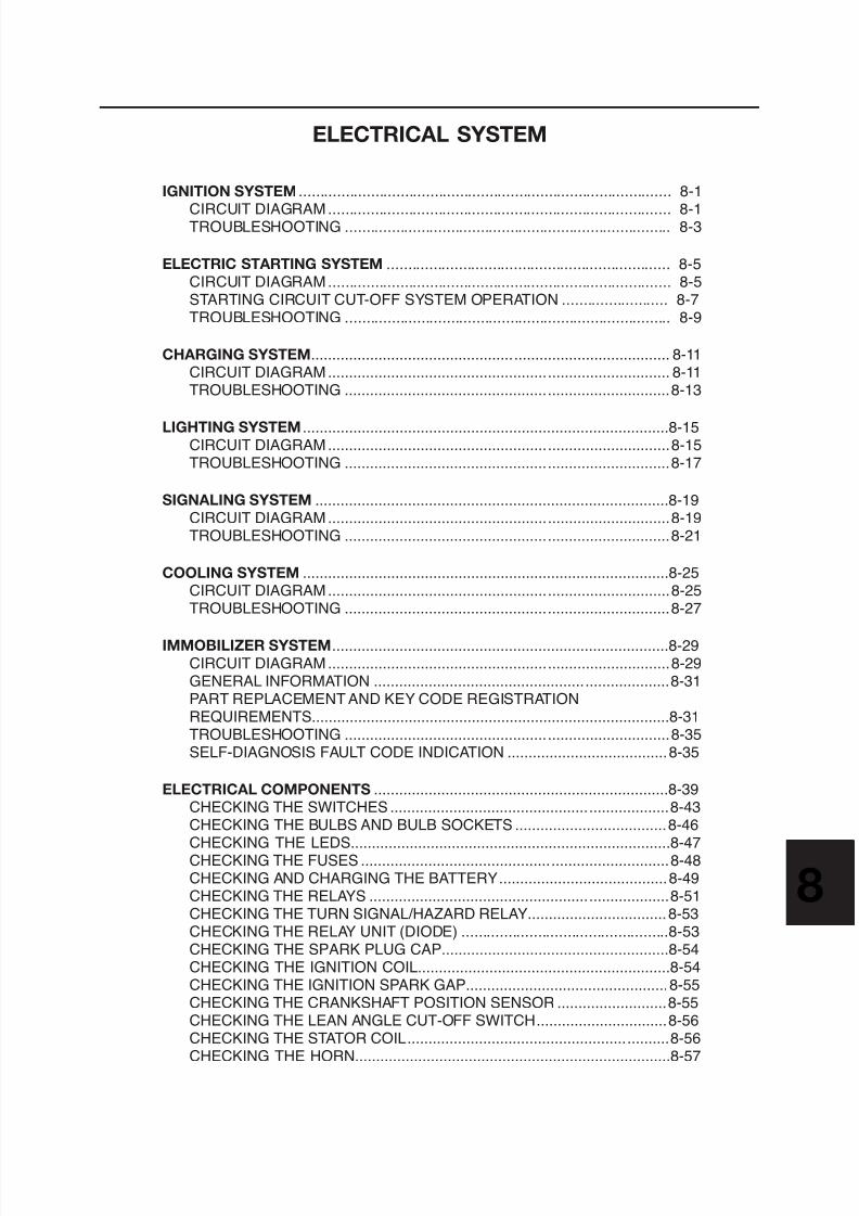
8/12/2019 Yamaha Tenere XT660Z Service Manual
http://slidepdf.com/reader/full/yamaha-tenere-xt660z-service-manual 325/398
ELECTRIC STARTING SYSTEM ................................................................... 8-5CIRCUIT DIAGRAM................................................................................. 8-5STARTING CIRCUIT CUT-OFF SYSTEM OPERATION ......................... 8-7TROUBLESHOOTING ............................................................................. 8-9
CHARGING SYSTEM..................................................................................... 8-11CIRCUIT DIAGRAM................................................................................. 8-11TROUBLESHOOTING .............................................................................8-13
LIGHTING SYSTEM .......................................................................................8-15CIRCUIT DIAGRAM.................................................................................8-15TROUBLESHOOTING .............................................................................8-17
SIGNALING SYSTEM ....................................................................................8-19CIRCUIT DIAGRAM.................................................................................8-19TROUBLESHOOTING .............................................................................8-21
COOLING SYSTEM .......................................................................................8-25CIRCUIT DIAGRAM.................................................................................8-25TROUBLESHOOTING .............................................................................8-27
IMMOBILIZER SYSTEM 8 29
CHECKING THE COOLANT TEMPERATURE SENSOR........................8-57CHECKING THE FUEL SENDER............................................................8-58CHECKING THE SPEED SENSOR.........................................................8-58CHECKING THE THROTTLE POSITION SENSOR................................8-59CHECKING THE FUEL PUMP.................................................................8-59
CHECKING THE INTAKE AIR PRESSURE SENSOR ............................8-60CHECKING THE INTAKE AIR TEMPERATURE SENSOR .....................8-60CHECKING THE RADIATOR FAN MOTOR ............................................8-60CHECKING THE STARTER MOTOR 8 61
8/12/2019 Yamaha Tenere XT660Z Service Manual
http://slidepdf.com/reader/full/yamaha-tenere-xt660z-service-manual 326/398
CHECKING THE STARTER MOTOR ......................................................8-61
IGNITION SYSTEM
EAS27090
IGNITION SYSTEM
EAS27110
CIRCUIT DIAGRAM
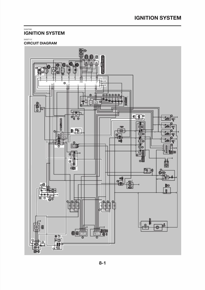
8/12/2019 Yamaha Tenere XT660Z Service Manual
http://slidepdf.com/reader/full/yamaha-tenere-xt660z-service-manual 327/398
IGNITION SYSTEM
1. Crankshaft position sensor
3. Neutral switch
4. Main switch
7. Battery
8. Main fuse
13. Starting circuit cut-off relay16. Ignition coil
17. Spark plug
23. ECU
27 Lean angle cut off switch
8/12/2019 Yamaha Tenere XT660Z Service Manual
http://slidepdf.com/reader/full/yamaha-tenere-xt660z-service-manual 328/398
27. Lean angle cut-off switch
39. Sidestand switch
42. Engine stop switch
46. Clutch switch
67. Ignition fuse
IGNITION SYSTEM
EAS27150
TROUBLESHOOTING
The ignition system fails to operate (no spark or intermittent spark).
NOTE:
• Before troubleshooting, remove the following part(s):1. Seat2. Side panels (left and right)3. Fuel tank
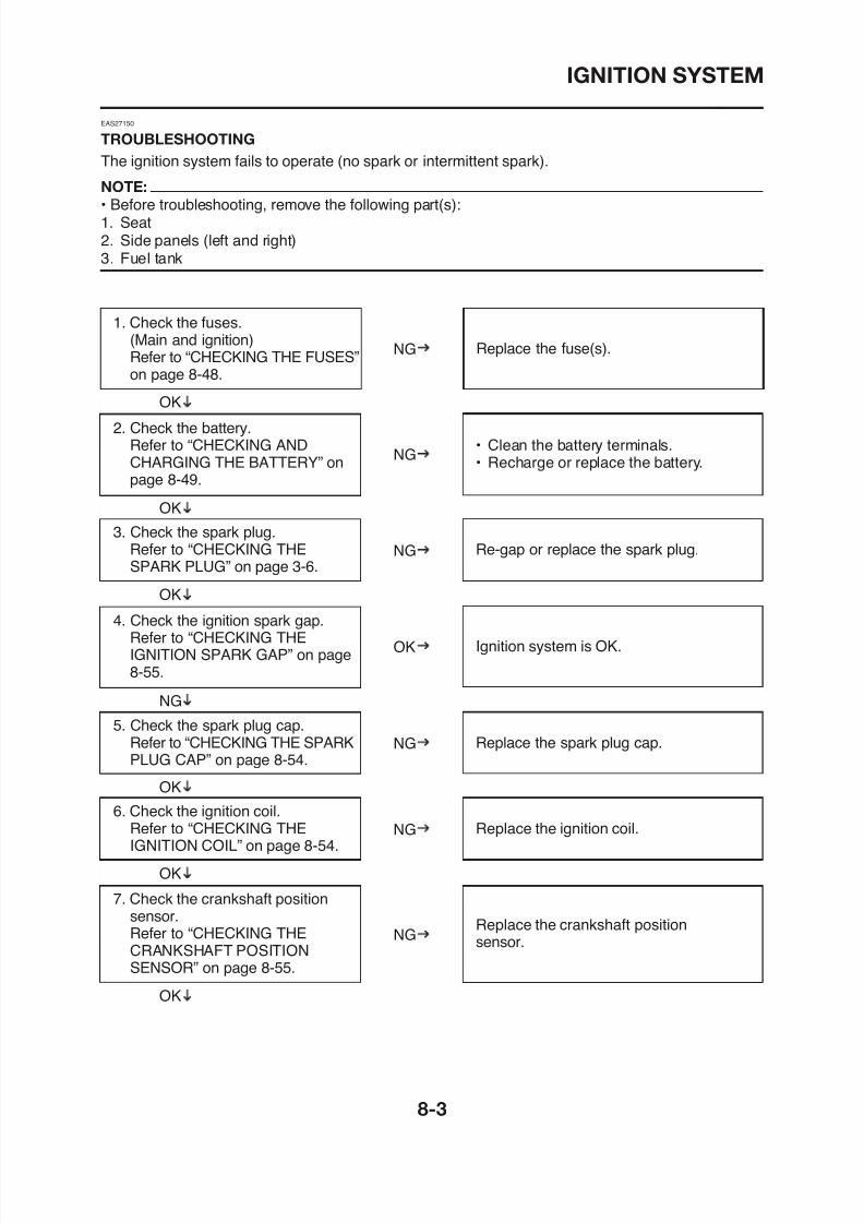
8/12/2019 Yamaha Tenere XT660Z Service Manual
http://slidepdf.com/reader/full/yamaha-tenere-xt660z-service-manual 329/398
1. Check the fuses.(Main and ignition)
Refer to “CHECKING THE FUSES”on page 8-48.
2. Check the battery.Refer to “CHECKING ANDCHARGING THE BATTERY” onpage 8-49.
4. Check the ignition spark gap.Refer to “CHECKING THE
3. Check the spark plug.Refer to “CHECKING THESPARK PLUG” on page 3-6.
Replace the fuse(s).
• Clean the battery terminals.• Recharge or replace the battery.
Ignition system is OK
Re-gap or replace the spark plug.
OK
OK
OK
NG
NG
NG
OK
IGNITION SYSTEM
8. Check the main switch.Refer to “CHECKING THESWITCHES” on page 8-43.
9. Check the engine stop switch.Refer to “CHECKING THESWITCHES” on page 8-43.
Replace the main switch/immobilizer unit.
Replace the right handlebar switch.
OK
NG
NG
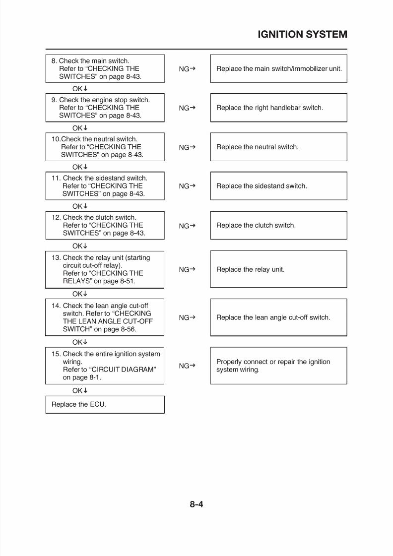
8/12/2019 Yamaha Tenere XT660Z Service Manual
http://slidepdf.com/reader/full/yamaha-tenere-xt660z-service-manual 330/398
OK
10.Check the neutral switch.Refer to “CHECKING THESWITCHES” on page 8-43.
11. Check the sidestand switch.Refer to “CHECKING THESWITCHES” on page 8-43.
12. Check the clutch switch.Refer to “CHECKING THE
SWITCHES” on page 8-43.
OK
OK
NG
NG
NG
OK
OK
13. Check the relay unit (startingcircuit cut-off relay).Refer to “CHECKING THERELAYS” on page 8-51.
NG
Replace the neutral switch.
Replace the sidestand switch.
Replace the clutch switch.
Replace the relay unit.
ELECTRIC STARTING SYSTEM
EAS27160
ELECTRIC STARTING SYSTEM
EAS27170
CIRCUIT DIAGRAM
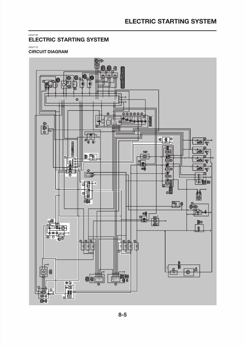
8/12/2019 Yamaha Tenere XT660Z Service Manual
http://slidepdf.com/reader/full/yamaha-tenere-xt660z-service-manual 331/398
ELECTRIC STARTING SYSTEM
3. Neutral switch
4. Main switch
7. Battery
8. Main fuse
9. Starter relay
10. Starter motor
12. Relay unit
13. Starting circuit cut-off relay
39. Sidestand switch
41 Start switch
8/12/2019 Yamaha Tenere XT660Z Service Manual
http://slidepdf.com/reader/full/yamaha-tenere-xt660z-service-manual 332/398
41. Start switch
42. Engine stop switch
46. Clutch switch
67. Ignition fuse
ELECTRIC STARTING SYSTEM
EAS27180
STARTING CIRCUIT CUT-OFF SYSTEM OPERATION
If the engine stop switch is set to “I” and the main switch is turned “ON” (both switch circuits areclosed), the starter motor can only operate if at least one of the following conditions is met:• The transmission is in neutral (the neutral switch circuit is closed).
• The clutch lever is pulled to the handlebar (the clutch switch circuit is closed) and the sidestand isup (the sidestand switch circuit is closed).
The starting circuit cut-off relay prevents the starter motor from operating when neither of these con-ditions has been met In this instance the starting circuit cut-off relay stays open so current cannot
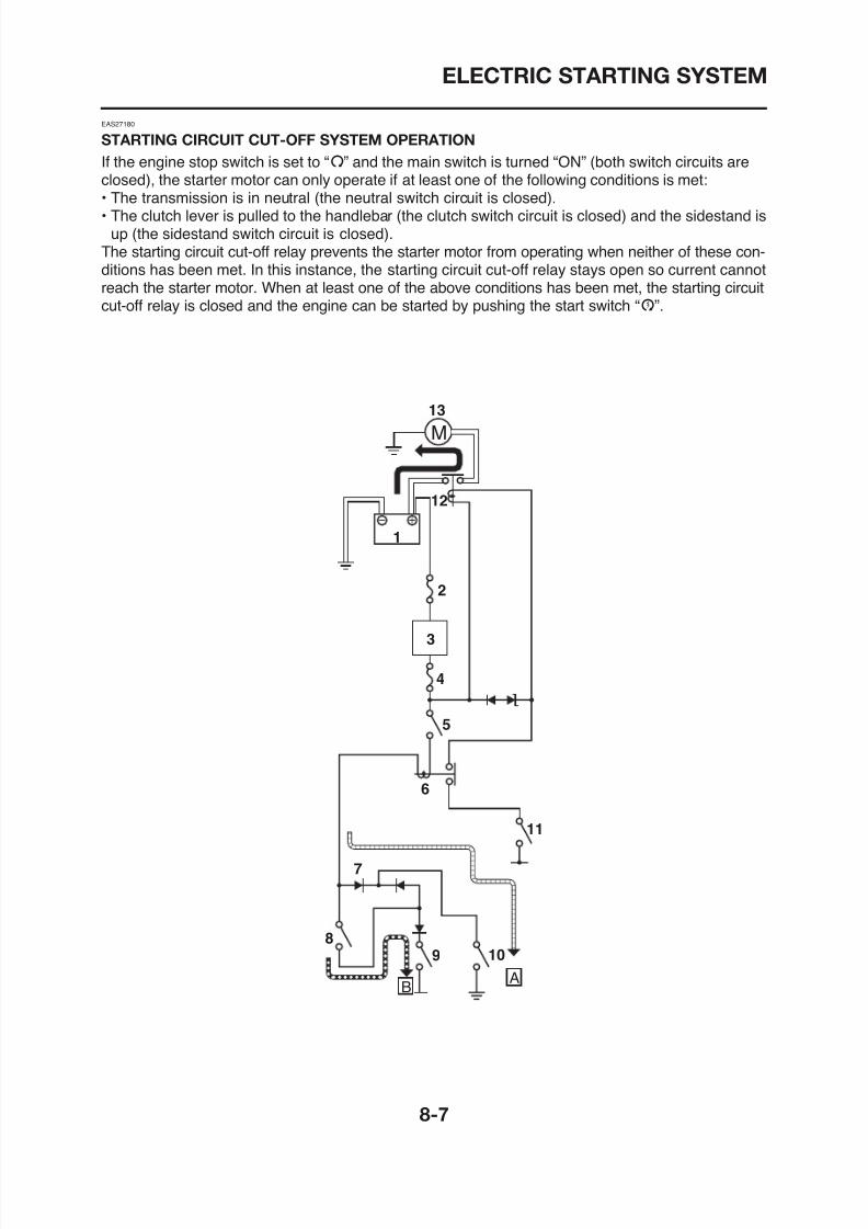
8/12/2019 Yamaha Tenere XT660Z Service Manual
http://slidepdf.com/reader/full/yamaha-tenere-xt660z-service-manual 333/398
ditions has been met. In this instance, the starting circuit cut off relay stays open so current cannotreach the starter motor. When at least one of the above conditions has been met, the starting circuitcut-off relay is closed and the engine can be started by pushing the start switch “J”.
M
13
12
1
2
3
ELECTRIC STARTING SYSTEM
å WHEN THE TRANSMISSION IS IN NEUTRAL
∫ WHEN THE SIDESTAND IS UP AND THE
CLUTCH LEVER IS PULLED TO THE
HANDLEBAR
1. Battery
2. Main fuse
3. Main switch
4. Ignition fuse
5. Engine stop switch
6 Relay unit (starting circuit cut-off relay)
8/12/2019 Yamaha Tenere XT660Z Service Manual
http://slidepdf.com/reader/full/yamaha-tenere-xt660z-service-manual 334/398
6. Relay unit (starting circuit cut off relay)
7. Relay unit (diode)
8. Clutch switch
9. Sidestand switch
10.Neutral switch
11. Start switch
12.Starter relay13.Starter motor
ELECTRIC STARTING SYSTEM
EAS27190
TROUBLESHOOTING
The starter motor fails to turn.
NOTE:
• Before troubleshooting, remove the following part(s):1. Seat2. Side panels (left and right)3. Fuel tank
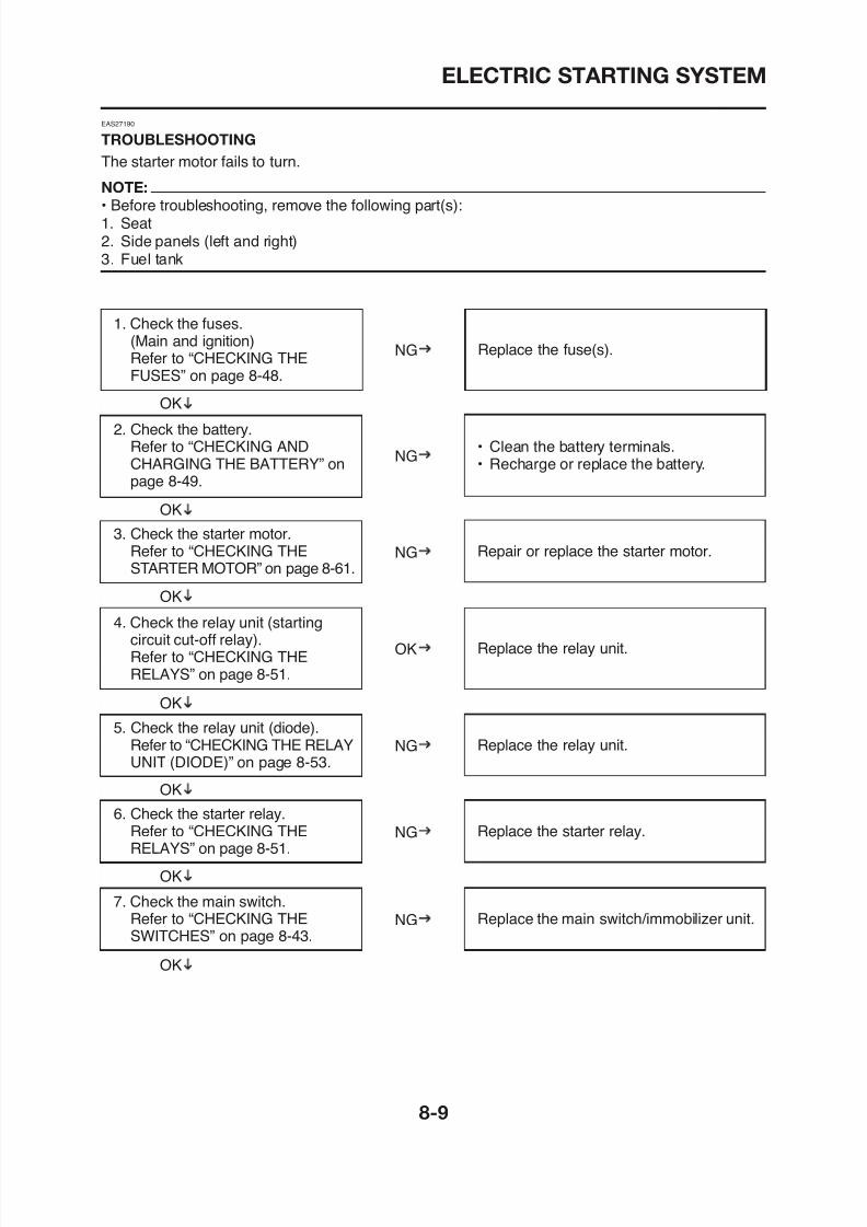
8/12/2019 Yamaha Tenere XT660Z Service Manual
http://slidepdf.com/reader/full/yamaha-tenere-xt660z-service-manual 335/398
1. Check the fuses.(Main and ignition)
Refer to “CHECKING THEFUSES” on page 8-48.
2. Check the battery.Refer to “CHECKING ANDCHARGING THE BATTERY” onpage 8-49.
4. Check the relay unit (startingcircuit cut-off relay).
3. Check the starter motor.Refer to “CHECKING THESTARTER MOTOR” on page 8-61.
Replace the fuse(s).
• Clean the battery terminals.• Recharge or replace the battery.
Replace the relay unit
Repair or replace the starter motor.
OK
OK
OK
NG
NG
NG
OK
ELECTRIC STARTING SYSTEM
8. Check the engine stop switch.Refer to “CHECKING THESWITCHES” on page 8-43.
9. Check the neutral switch.Refer to “CHECKING THESWITCHES” on page 8-43.
Replace the right handlebar switch.
Replace the neutral switch.
OK
NG
NG
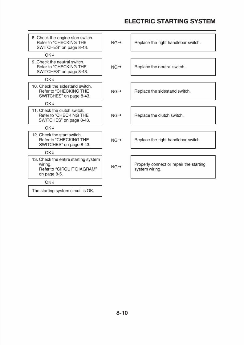
8/12/2019 Yamaha Tenere XT660Z Service Manual
http://slidepdf.com/reader/full/yamaha-tenere-xt660z-service-manual 336/398
OK
10. Check the sidestand switch.Refer to “CHECKING THESWITCHES” on page 8-43.
11. Check the clutch switch.Refer to “CHECKING THESWITCHES” on page 8-43.
12. Check the start switch.Refer to “CHECKING THE
SWITCHES” on page 8-43.
OK
OK
NG
NG
NG
OK
13. Check the entire starting systemwiring.Refer to “CIRCUIT DIAGRAM”on page 8-5.
Replace the sidestand switch.
Replace the clutch switch.
Replace the right handlebar switch.
Properly connect or repair the startingsystem wiring.
NG
OK
CHARGING SYSTEM
EAS27200
CHARGING SYSTEM
EAS27210
CIRCUIT DIAGRAM
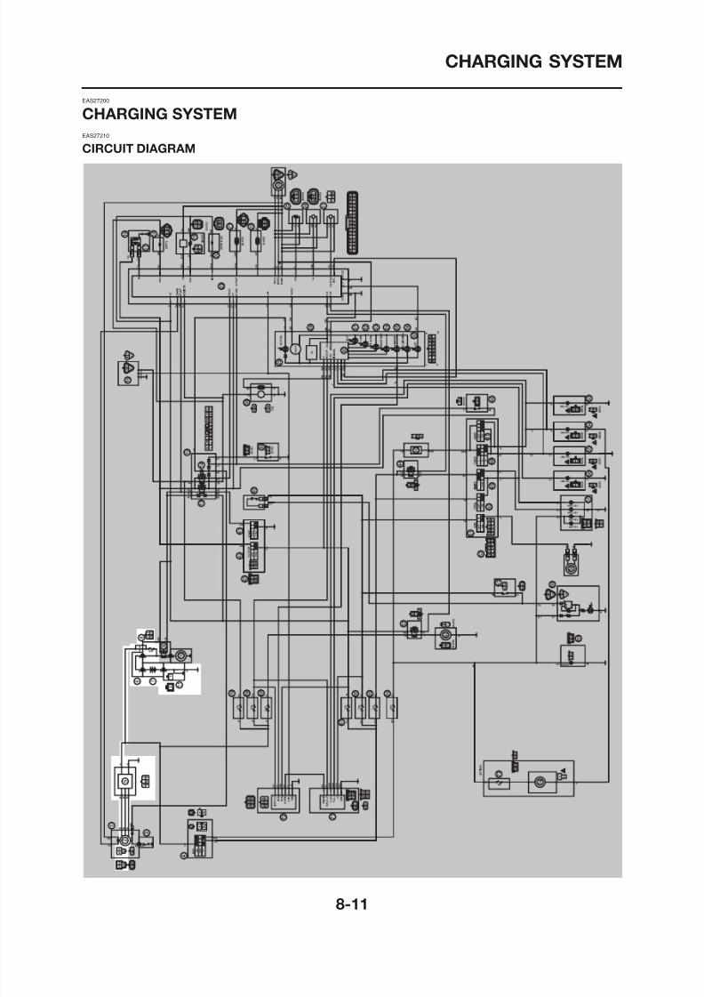
8/12/2019 Yamaha Tenere XT660Z Service Manual
http://slidepdf.com/reader/full/yamaha-tenere-xt660z-service-manual 337/398
CHARGING SYSTEM
2. A.C. magneto
5. Rectifier/regulator
7. Battery
8. Main fuse
8/12/2019 Yamaha Tenere XT660Z Service Manual
http://slidepdf.com/reader/full/yamaha-tenere-xt660z-service-manual 338/398
CHARGING SYSTEM
EAS27220
TROUBLESHOOTING
The battery is not being charged.
NOTE:
• Before troubleshooting, remove the following part(s):1. Seat2. Side panels (left and right)3. Fuel tank
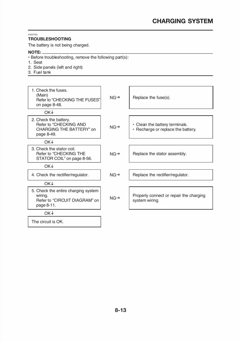
8/12/2019 Yamaha Tenere XT660Z Service Manual
http://slidepdf.com/reader/full/yamaha-tenere-xt660z-service-manual 339/398
1. Check the fuses.(Main)
Refer to “CHECKING THE FUSES”on page 8-48.
2. Check the battery.Refer to “CHECKING ANDCHARGING THE BATTERY” onpage 8-49.
4. Check the rectifier/regulator.
3. Check the stator coil.Refer to “CHECKING THESTATOR COIL” on page 8-56.
Replace the fuse(s).
• Clean the battery terminals.• Recharge or replace the battery.
Replace the rectifier/regulator.
Replace the stator assembly.
OK
OK
OK
NG
NG
NG
NG
CHARGING SYSTEM

8/12/2019 Yamaha Tenere XT660Z Service Manual
http://slidepdf.com/reader/full/yamaha-tenere-xt660z-service-manual 340/398
LIGHTING SYSTEM
EAS27240
LIGHTING SYSTEM
EAS27250
CIRCUIT DIAGRAM
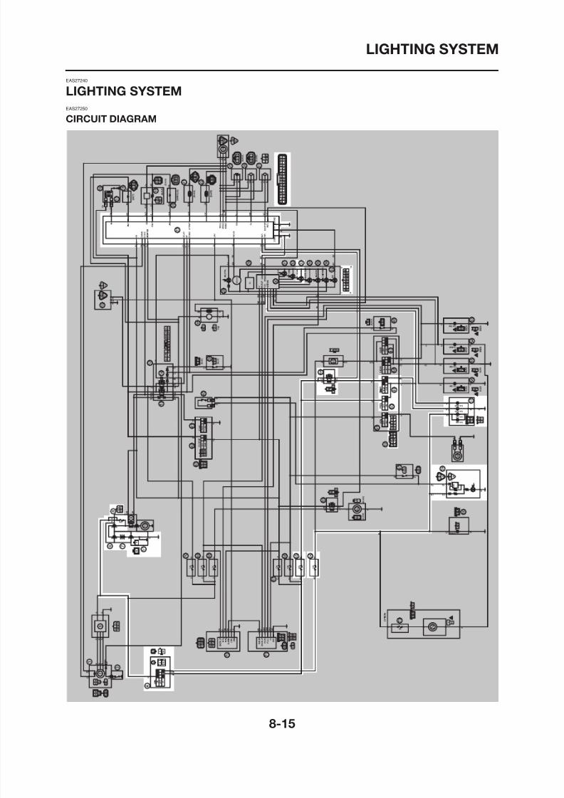
8/12/2019 Yamaha Tenere XT660Z Service Manual
http://slidepdf.com/reader/full/yamaha-tenere-xt660z-service-manual 341/398
LIGHTING SYSTEM
4. Main switch
7. Battery
8. Main fuse
23. ECU
33. High beam indicator light
44. Headlight relay
49. Dimmer switch
50. Pass switch
57. Headlight
59. Tail/brake light
8/12/2019 Yamaha Tenere XT660Z Service Manual
http://slidepdf.com/reader/full/yamaha-tenere-xt660z-service-manual 342/398
64. Parking lighting fuse
65. Headlight fuse
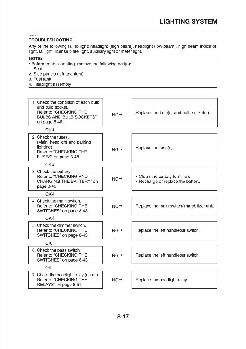
8/12/2019 Yamaha Tenere XT660Z Service Manual
http://slidepdf.com/reader/full/yamaha-tenere-xt660z-service-manual 343/398
LIGHTING SYSTEM
8. Check the high beam indicatorlight LED. Refer to “CHECKINGTHE LEDS” on page 8-47.
Replace the meter assembly.NG
9. Check the meter light LED.Refer to “CHECKING THE LEDS”on page 8-47.
Replace the meter assembly.
OK
NG
OK
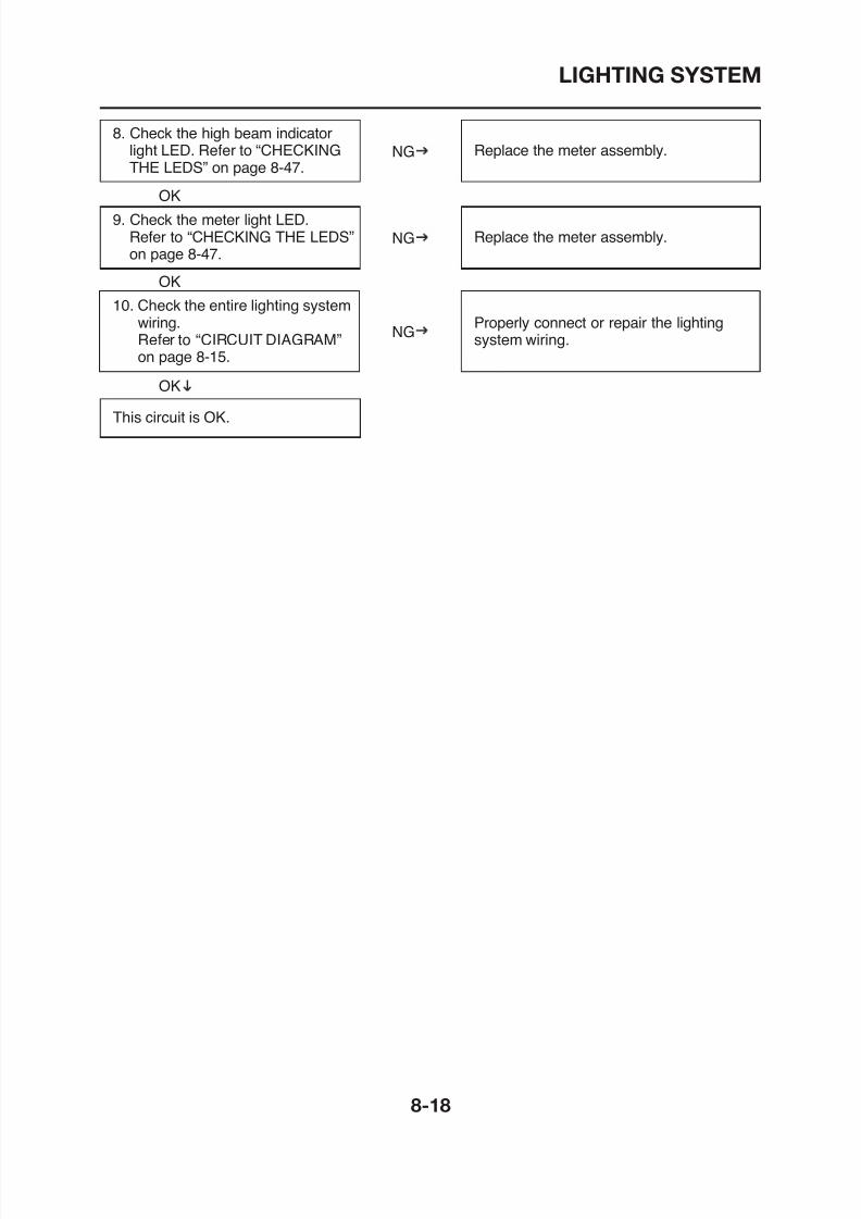
8/12/2019 Yamaha Tenere XT660Z Service Manual
http://slidepdf.com/reader/full/yamaha-tenere-xt660z-service-manual 344/398
10. Check the entire lighting systemwiring.Refer to “CIRCUIT DIAGRAM”
on page 8-15.
Properly connect or repair the lightingsystem wiring.
NG
OK
OK
This circuit is OK.
SIGNALING SYSTEM
EAS27270
SIGNALING SYSTEM
EAS27280
CIRCUIT DIAGRAM
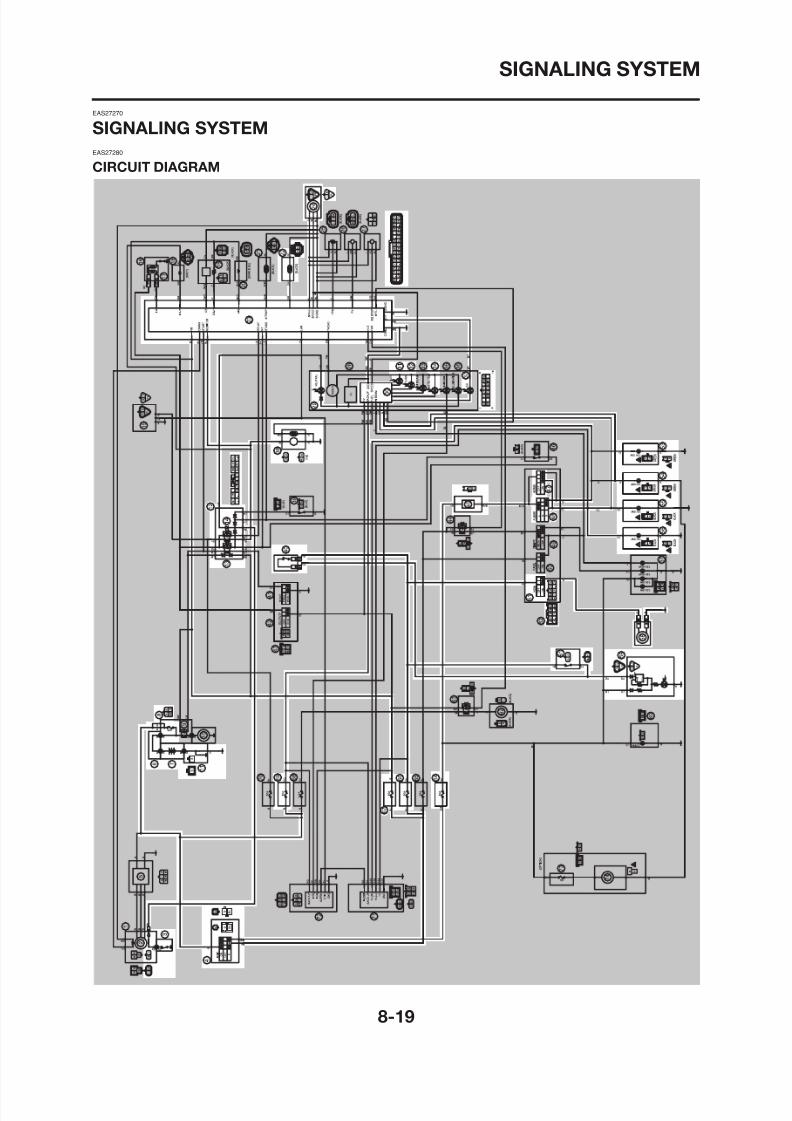
8/12/2019 Yamaha Tenere XT660Z Service Manual
http://slidepdf.com/reader/full/yamaha-tenere-xt660z-service-manual 345/398
SIGNALING SYSTEM
3. Neutral switch
4. Main switch
7. Battery
8. Main fuse
12. Relay unit
22. Coolant temperature sensor
23. ECU
24. Speed sensor
29. Neutral indicator light
30. Multi-function meter
31 F l t
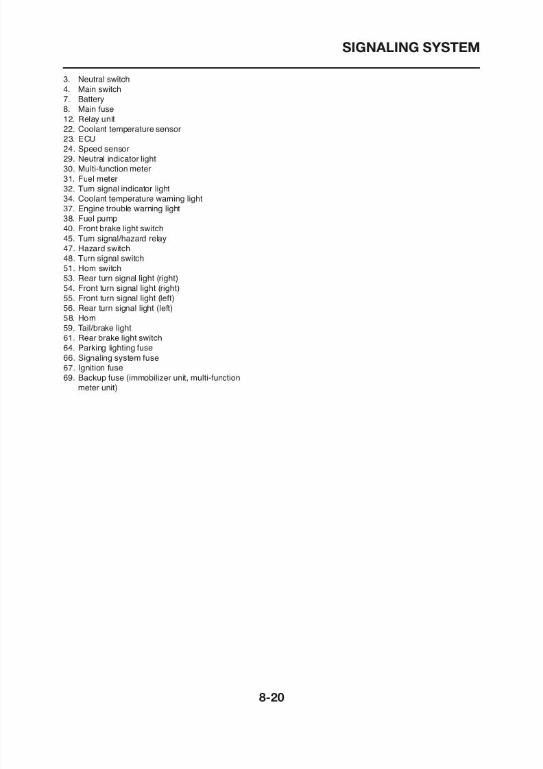
8/12/2019 Yamaha Tenere XT660Z Service Manual
http://slidepdf.com/reader/full/yamaha-tenere-xt660z-service-manual 346/398
31. Fuel meter
32. Turn signal indicator light
34. Coolant temperature warning light
37. Engine trouble warning light
38. Fuel pump
40. Front brake light switch45. Turn signal/hazard relay
47. Hazard switch
48. Turn signal switch
51. Horn switch
53. Rear turn signal light (right)
54. Front turn signal light (right)
55. Front turn signal light (left)
56. Rear turn signal light (left)
58. Horn
59. Tail/brake light61. Rear brake light switch
64. Parking lighting fuse
66. Signaling system fuse
67. Ignition fuse
69. Backup fuse (immobilizer unit, multi-function
meter unit)
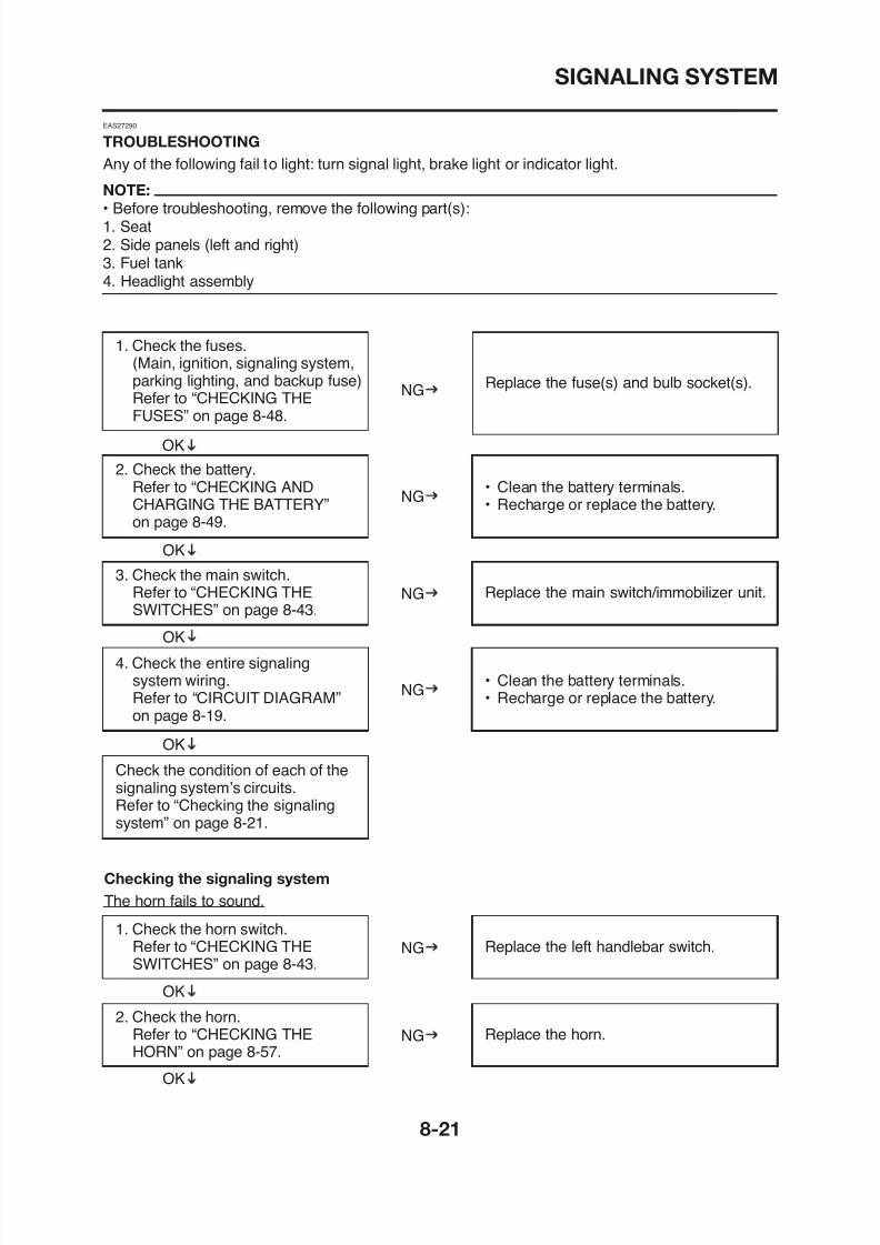
8/12/2019 Yamaha Tenere XT660Z Service Manual
http://slidepdf.com/reader/full/yamaha-tenere-xt660z-service-manual 347/398
SIGNALING SYSTEM
3. Check the entire signaling systemwiring.Refer to “CIRCUIT DIAGRAM” onpage 8-19.
Properly connect or repair the signalingsystem wiring.
NG
OK
The circuit is OK.
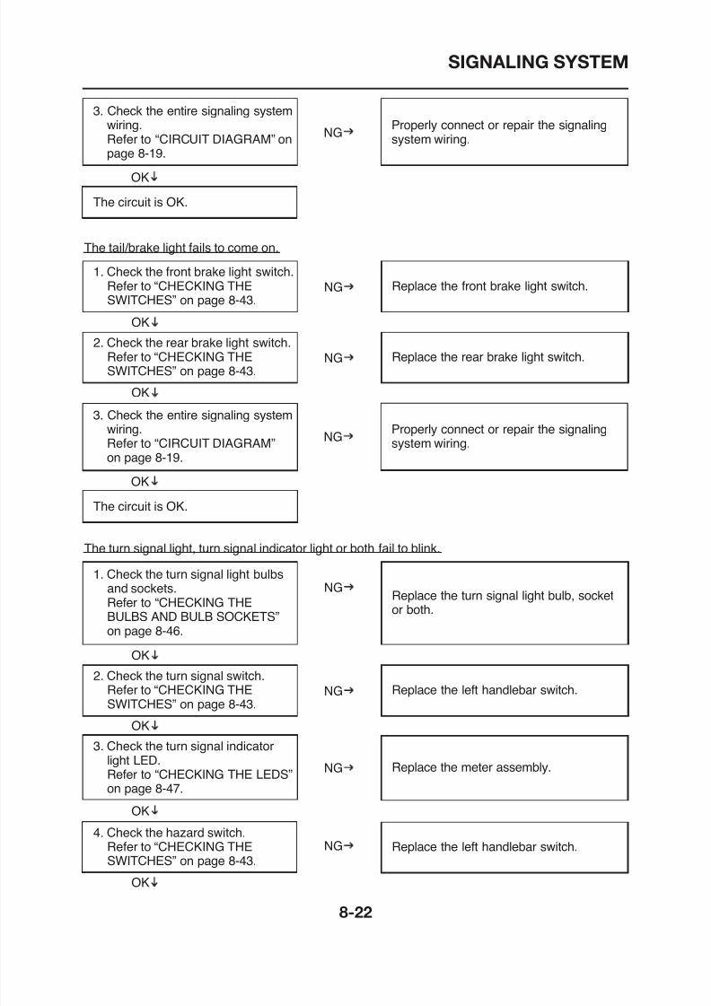
8/12/2019 Yamaha Tenere XT660Z Service Manual
http://slidepdf.com/reader/full/yamaha-tenere-xt660z-service-manual 348/398
OK
OK
1. Check the front brake light switch.Refer to “CHECKING THE
SWITCHES” on page 8-43.
Replace the front brake light switch.NG
2. Check the rear brake light switch.Refer to “CHECKING THESWITCHES” on page 8-43.
Replace the rear brake light switch.NG
The tail/brake light fails to come on.
3. Check the entire signaling system
wiring.Refer to “CIRCUIT DIAGRAM”on page 8-19.
Properly connect or repair the signalingsystem wiring.
NG
OK
The circuit is OK.
SIGNALING SYSTEM
OK
5. Check the turn signal/hazardrelay. Refer to “CHECKING THETURN SIGNAL/HAZARD RELAY”on page 8-53.
Replace the turn signal/hazard relay.NG
6. Check the entire signaling systemwiring.Refer to “CIRCUIT DIAGRAM”
Properly connect or repair the signalingsystem wiring.
NG
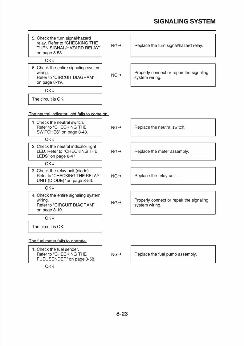
8/12/2019 Yamaha Tenere XT660Z Service Manual
http://slidepdf.com/reader/full/yamaha-tenere-xt660z-service-manual 349/398
on page 8-19.
OK
The circuit is OK.
OK
1. Check the neutral switch.Refer to “CHECKING THESWITCHES” on page 8-43.
Replace the neutral switch.NG
3. Check the relay unit (diode).Refer to “CHECKING THE RELAYUNIT (DIODE)” on page 8-53.
Replace the relay unit.NG
OK
2. Check the neutral indicator lightLED. Refer to “CHECKING THELEDS” on page 8-47.
Replace the meter assembly.NG
The neutral indicator light fails to come on.
SIGNALING SYSTEM
2. Check the entire signaling systemwiring.Refer to “CIRCUIT DIAGRAM”on page 8-19.
Properly connect or repair the signalingsystem wiring.
NG
OK
Replace the meter assembly.
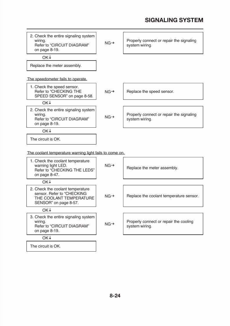
8/12/2019 Yamaha Tenere XT660Z Service Manual
http://slidepdf.com/reader/full/yamaha-tenere-xt660z-service-manual 350/398
1. Check the speed sensor.Refer to “CHECKING THE
SPEED SENSOR” on page 8-58.
Replace the speed sensor.NG
OK
2. Check the entire signaling systemwiring.Refer to “CIRCUIT DIAGRAM”on page 8-19.
Properly connect or repair the signalingsystem wiring.
NG
The speedometer fails to operate.
OK
The circuit is OK.
1. Check the coolant temperaturewarning light LED.Refer to “CHECKING THE LEDS”
Replace the meter assembly.NG
The coolant temperature warning light fails to come on.
COOLING SYSTEM
EAS00807
COOLING SYSTEM
CIRCUIT DIAGRAM
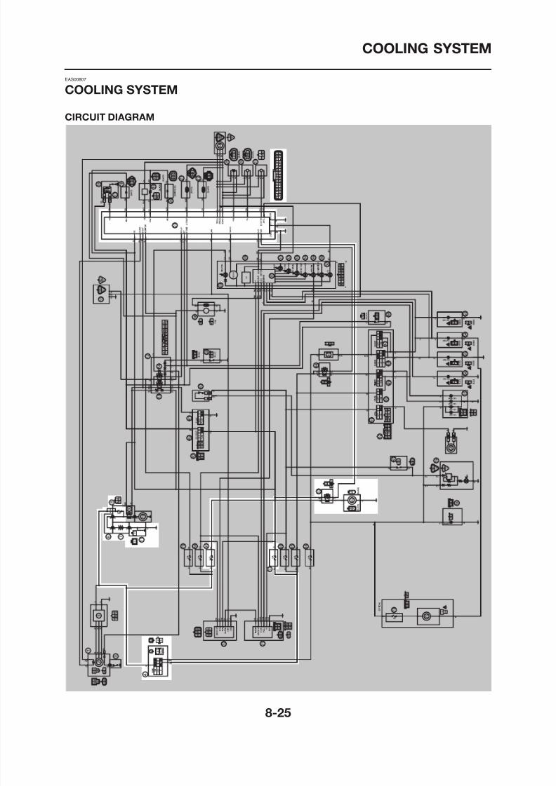
8/12/2019 Yamaha Tenere XT660Z Service Manual
http://slidepdf.com/reader/full/yamaha-tenere-xt660z-service-manual 351/398
COOLING SYSTEM
4. Main switch
7. Battery
8. Main fuse
23. ECU
62. Radiator fan motor
63. Radiator fan motor relay
67. Ignition fuse68. Radiator fan motor fuse
8/12/2019 Yamaha Tenere XT660Z Service Manual
http://slidepdf.com/reader/full/yamaha-tenere-xt660z-service-manual 352/398
COOLING SYSTEM
EAS27570
TROUBLESHOOTING
If the radiator fan motor fails to operate.
NOTE:
• Before troubleshooting, remove the following part(s):
1. Seat2. Side panels (left and right)3. Fuel tank
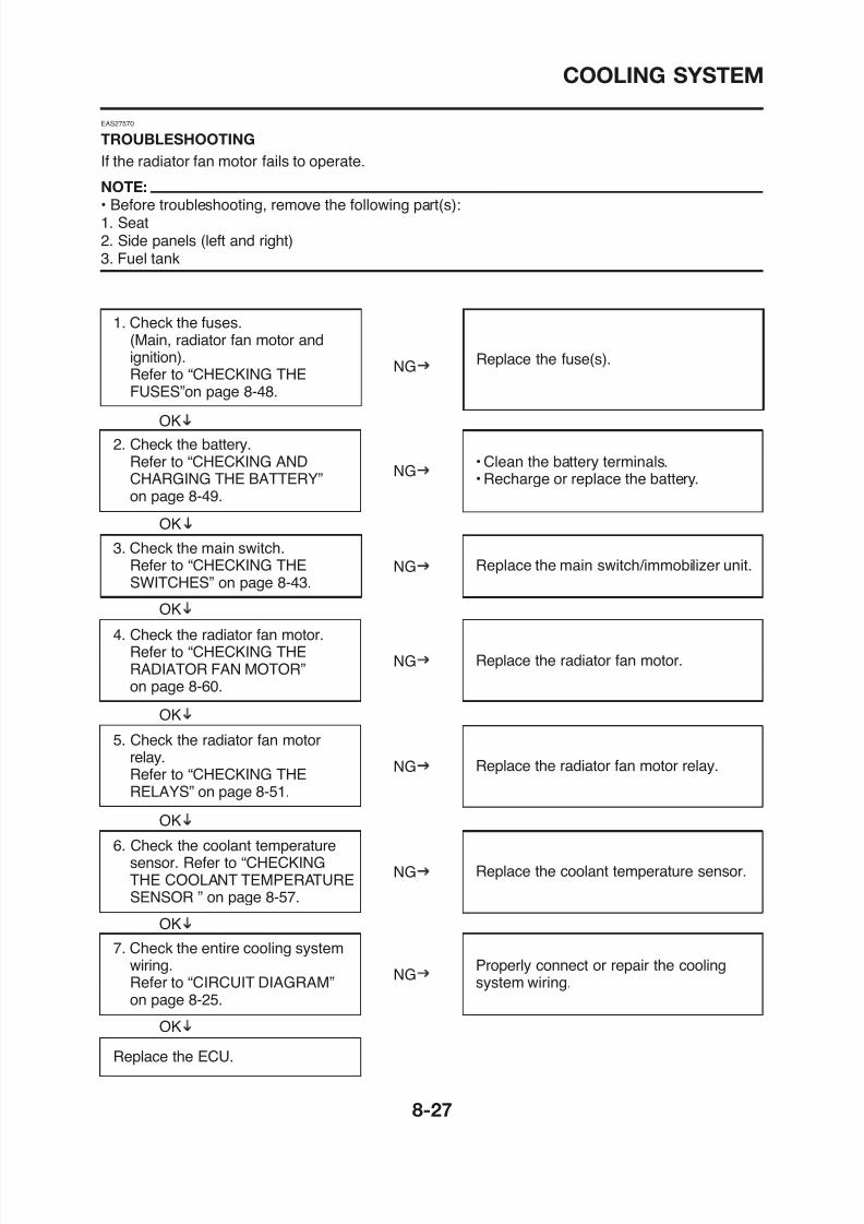
8/12/2019 Yamaha Tenere XT660Z Service Manual
http://slidepdf.com/reader/full/yamaha-tenere-xt660z-service-manual 353/398
1. Check the fuses.(Main, radiator fan motor andignition).Refer to “CHECKING THEFUSES”on page 8-48.
2. Check the battery.Refer to “CHECKING ANDCHARGING THE BATTERY”on page 8-49.
Replace the fuse(s).
• Clean the battery terminals.• Recharge or replace the battery.
NG
OK
NG
4. Check the radiator fan motor.Refer to “CHECKING THE
3. Check the main switch.Refer to “CHECKING THESWITCHES” on page 8-43.
Replace the main switch/immobilizer unit.
OK
NG
OK
COOLING SYSTEM

8/12/2019 Yamaha Tenere XT660Z Service Manual
http://slidepdf.com/reader/full/yamaha-tenere-xt660z-service-manual 354/398
IMMOBILIZER SYSTEM
ET5YU1002
IMMOBILIZER SYSTEM
ET5YU1003
CIRCUIT DIAGRAM
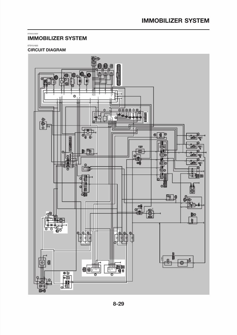
8/12/2019 Yamaha Tenere XT660Z Service Manual
http://slidepdf.com/reader/full/yamaha-tenere-xt660z-service-manual 355/398
IMMOBILIZER SYSTEM
4. Main switch
7. Battery
8. Main fuse
23. ECU
28. Multi-function meter unit
35. Immobilizer system indicator light
67. Ignition fuse69. Backup fuse (immobilizer unit, multi-function meter
unit)
71. Anti-theft alarm (optional)
72. Immobilizer unit
8/12/2019 Yamaha Tenere XT660Z Service Manual
http://slidepdf.com/reader/full/yamaha-tenere-xt660z-service-manual 356/398
IMMOBILIZER SYSTEM
EAS27670
GENERAL INFORMATION
This vehicle is equipped with an immobilizer system to help prevent theft by re-registering codes inthe standard keys. This system consists of the following:• a code re-registering key (with a red bow)
• two standard keys (with a black bow) that can be re-registered with new codes• a transponder (installed in the red key bow)• an immobilizer unit• the ECU• an immobilizer system indicator light
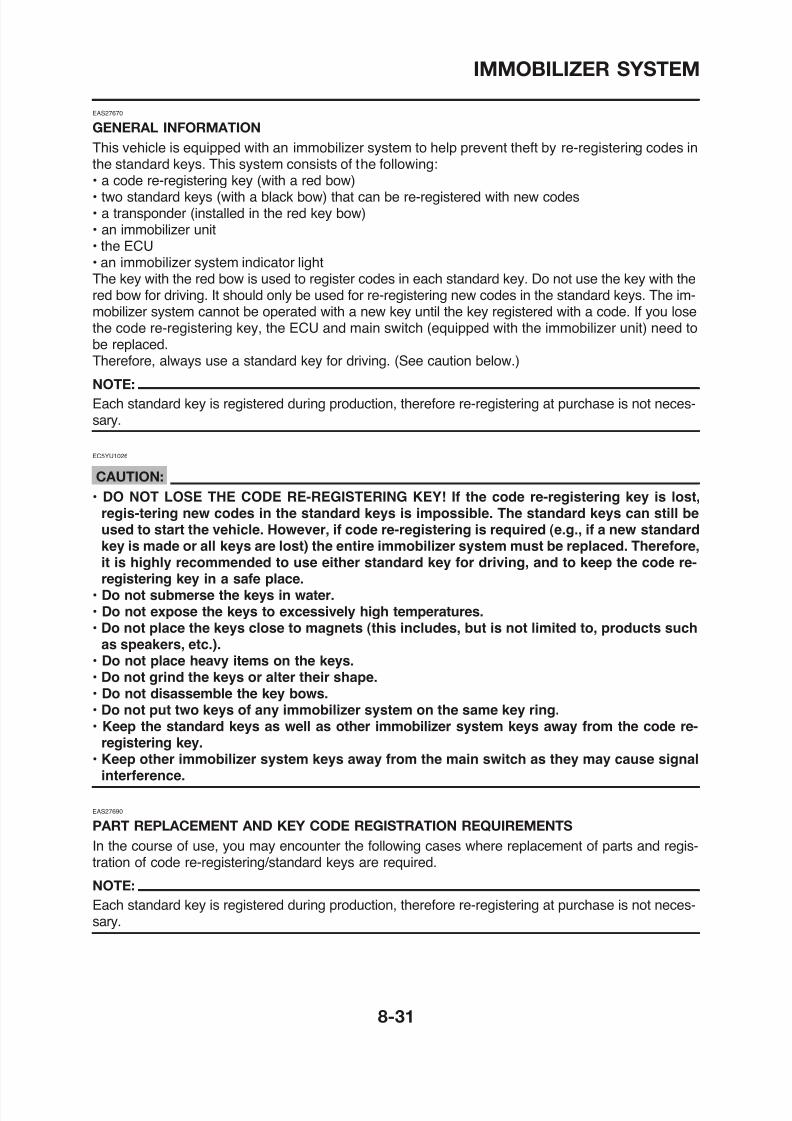
8/12/2019 Yamaha Tenere XT660Z Service Manual
http://slidepdf.com/reader/full/yamaha-tenere-xt660z-service-manual 357/398
an immobilizer system indicator lightThe key with the red bow is used to register codes in each standard key. Do not use the key with thered bow for driving. It should only be used for re-registering new codes in the standard keys. The im-mobilizer system cannot be operated with a new key until the key registered with a code. If you losethe code re-registering key, the ECU and main switch (equipped with the immobilizer unit) need tobe replaced.Therefore, always use a standard key for driving. (See caution below.)
NOTE:
Each standard key is registered during production, therefore re-registering at purchase is not neces-sary.
EC5YU1026
CAUTION:• DO NOT LOSE THE CODE RE-REGISTERING KEY! If the code re-registering key is lost,
regis-tering new codes in the standard keys is impossible. The standard keys can still beused to start the vehicle. However, if code re-registering is required (e.g., if a new standardkey is made or all keys are lost) the entire immobilizer system must be replaced. Therefore,it is highly recommended to use either standard key for driving, and to keep the code re-registering key in a safe place.
• Do not submerse the keys in water
Parts to be replaced
Key registrationrequirement
Main switch/immo-bilizer unit Standard
key
ECUAccesso-ry lock*
and keyMainswitch
Immobiliz-er unit
Standard key is lost √ New standard key
All keys have been Code re-registering
IMMOBILIZER SYSTEM
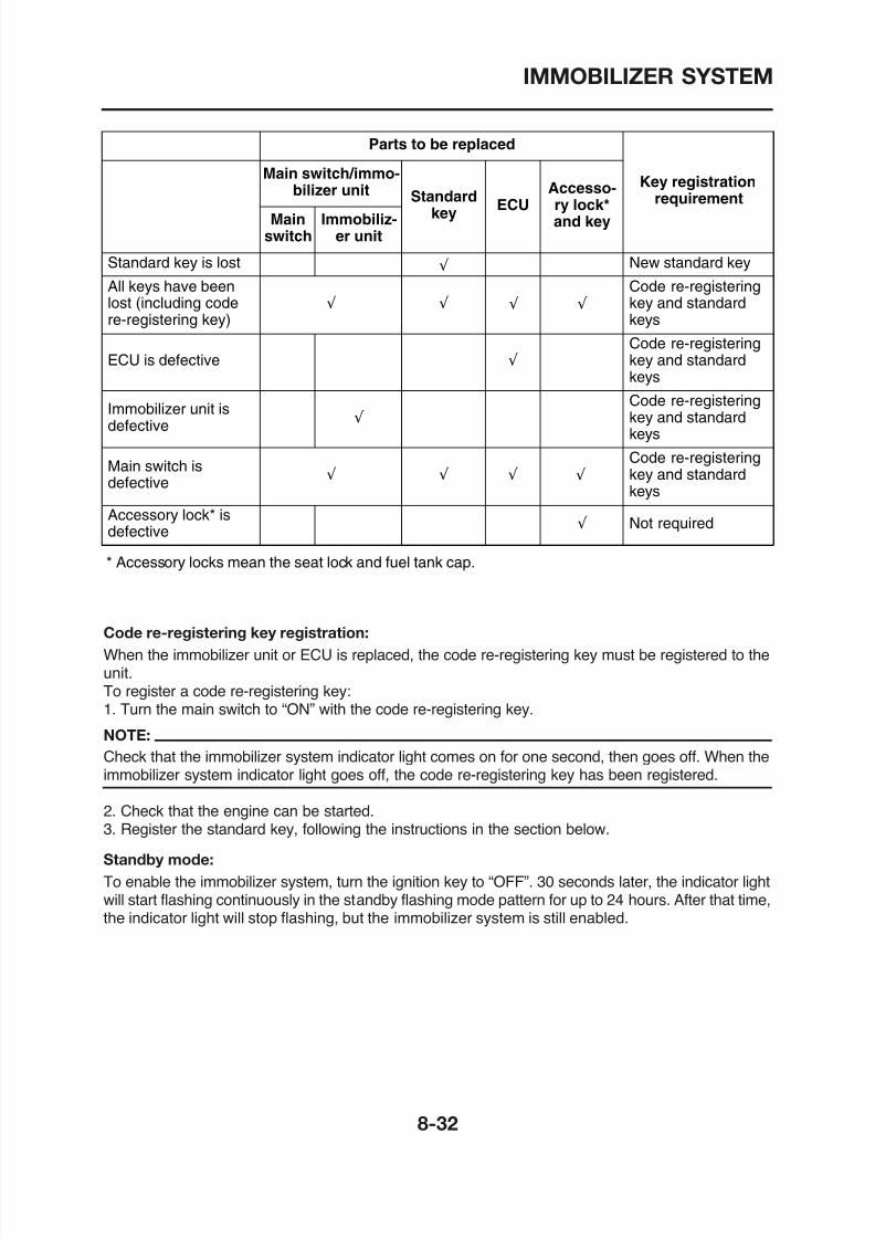
8/12/2019 Yamaha Tenere XT660Z Service Manual
http://slidepdf.com/reader/full/yamaha-tenere-xt660z-service-manual 358/398
* Accessory locks mean the seat lock and fuel tank cap.
lost (including codere-registering key)
√ √
g gkey and standardkeys
ECU is defective √
Code re-registeringkey and standard
keys
Immobilizer unit isdefective
√
Code re-registeringkey and standardkeys
Main switch isdefective
√ √
Code re-registeringkey and standardkeys
Accessory lock* isdefective √ Not required
√
√
√
√
Code re-registering key registration:
When the immobilizer unit or ECU is replaced the code re-registering key must be registered to the
IMMOBILIZER SYSTEM
Standby mode
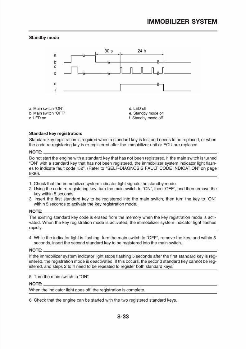
8/12/2019 Yamaha Tenere XT660Z Service Manual
http://slidepdf.com/reader/full/yamaha-tenere-xt660z-service-manual 359/398
a. Main switch “ON”b. Main switch “OFF”c. LED on
d. LED offe. Standby mode onf. Standby mode off
Standard key registration:
Standard key registration is required when a standard key is lost and needs to be replaced, or whenthe code re-registering key is re-registered after the immobilizer unit or ECU are replaced.
NOTE:
Do not start the engine with a standard key that has not been registered. If the main switch is turned“ON” with a standard key that has not been registered, the immobilizer system indicator light flash-es to indicate fault code “52”. (Refer to “SELF-DIAGNOSIS FAULT CODE INDICATION” on page8-36).
1. Check that the immobilizer system indicator light signals the standby mode.
IMMOBILIZER SYSTEM
Standard key registration
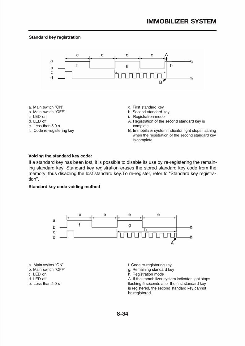
8/12/2019 Yamaha Tenere XT660Z Service Manual
http://slidepdf.com/reader/full/yamaha-tenere-xt660z-service-manual 360/398
a. Main switch “ON”b. Main switch “OFF”c. LED ond. LED offe. Less than 5.0 sf. Code re-registering key
g. First standard keyh. Second standard keyi. Registration modeA. Registration of the second standard key is
complete.B. Immobilizer system indicator light stops flashing
when the registration of the second standard keyis complete.
Voiding the standard key code:
If a standard key has been lost, it is possible to disable its use by re-registering the remain-
ing standard key. Standard key registration erases the stored standard key code from thememory, thus disabling the lost standard key.To re-register, refer to “Standard key registra-tion”.
IMMOBILIZER SYSTEM
EAS27700
TROUBLESHOOTING
When the main switch is turned to “ON”, the immobilizer system indicator light does not come on norflashes.
NOTE:
• Before troubleshooting, remove the following part(s):1. Seat2. Side panels (left and right)3. Fuel tank
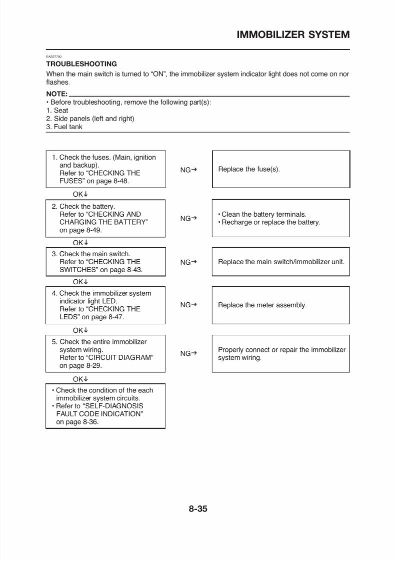
8/12/2019 Yamaha Tenere XT660Z Service Manual
http://slidepdf.com/reader/full/yamaha-tenere-xt660z-service-manual 361/398
1. Check the fuses. (Main, ignitionand backup).Refer to “CHECKING THEFUSES” on page 8-48.
2. Check the battery.Refer to “CHECKING ANDCHARGING THE BATTERY”on page 8-49.
Replace the fuse(s).
• Clean the battery terminals.• Recharge or replace the battery.
NG
OK
NG
3. Check the main switch.Refer to “CHECKING THESWITCHES” on page 8-43.
Replace the main switch/immobilizer unit.
OK
NG
4. Check the immobilizer system
OK
IMMOBILIZER SYSTEM
Fault Part Symptom Cause Actioncode
51 IMMOBILIZER Code cannot be 1. Radio wave 1. Keep magnets,UNIT transmitted between interference caused metal objects,
the key and the by objects around the and other
EAS27720
SELF-DIAGNOSIS FAULT CODE INDICATION
When a system malfunction occurs, the fault code number is signaled by the immobilizer system in-dicator light.
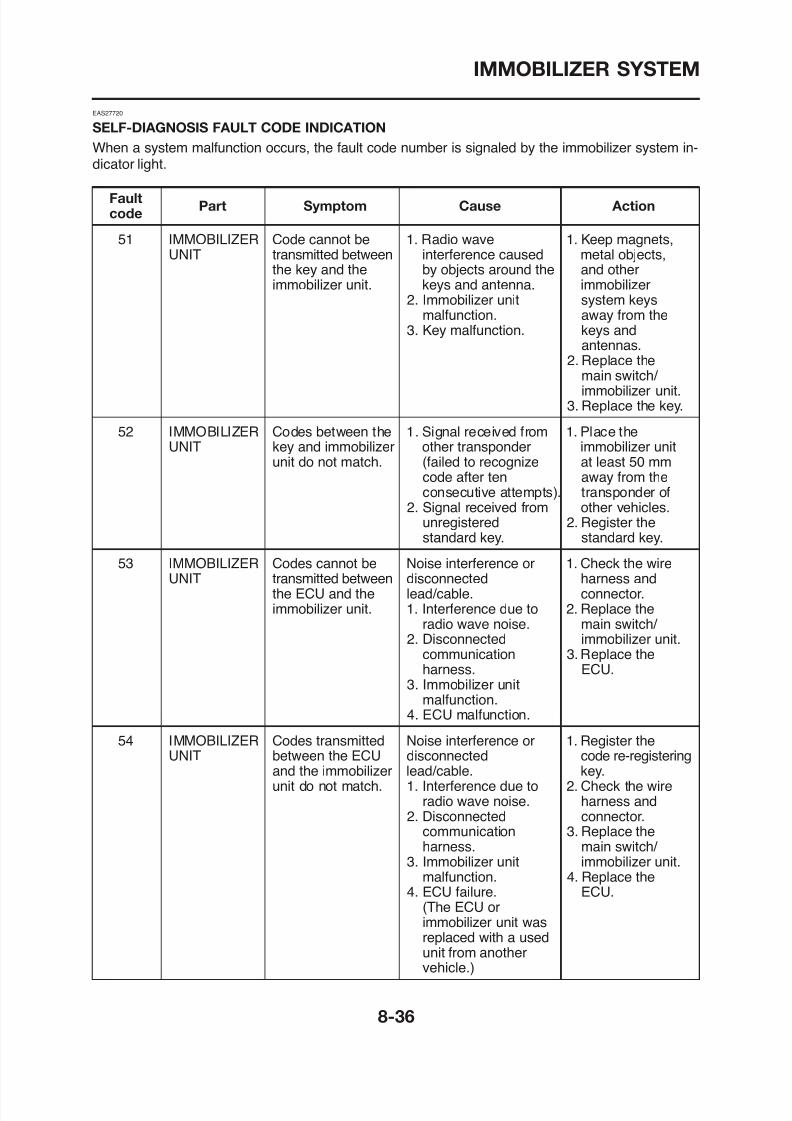
8/12/2019 Yamaha Tenere XT660Z Service Manual
http://slidepdf.com/reader/full/yamaha-tenere-xt660z-service-manual 362/398
the key and the by objects around the and otherimmobilizer unit. keys and antenna. immobilizer
2. Immobilizer unit system keysmalfunction. away from the
3. Key malfunction. keys andantennas.
2. Replace themain switch/ immobilizer unit.
3. Replace the key.
52 IMMOBILIZER Codes between the 1. Signal received from 1. Place theUNIT key and immobilizer other transponder immobilizer unit
unit do not match. (failed to recognize at least 50 mm
code after ten away from theconsecutive attempts). transponder of
2. Signal received from other vehicles.unregistered 2. Register thestandard key. standard key.
53 IMMOBILIZER Codes cannot be Noise interference or 1. Check the wireUNIT transmitted between disconnected harness and
the ECU and the lead/cable connector
IMMOBILIZER SYSTEM
FaultPart Symptom Cause Action
code
55 IMMOBILIZER Key code Same standard key Register anotherUNIT registration was attempted to be standard key.
malfunction. registered twoconsecutive times.
56 ECU Unidentified code Noise interference 1. Check the wireis received. or disconnected harness and
lead/cable. connector.
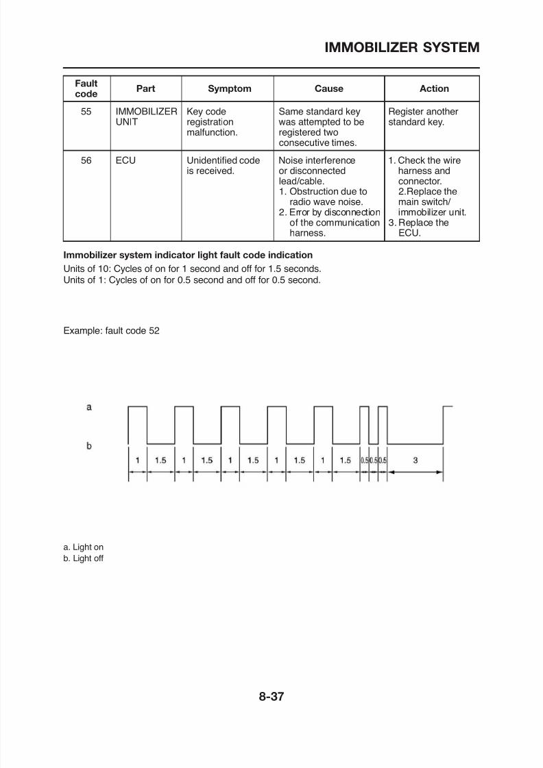
8/12/2019 Yamaha Tenere XT660Z Service Manual
http://slidepdf.com/reader/full/yamaha-tenere-xt660z-service-manual 363/398
1. Obstruction due to 2.Replace theradio wave noise. main switch/
2. Error by disconnection immobilizer unit.of the communication 3. Replace the
harness. ECU.
Immobilizer system indicator light fault code indication
Units of 10: Cycles of on for 1 second and off for 1.5 seconds.Units of 1: Cycles of on for 0.5 second and off for 0.5 second.
Example: fault code 52
IMMOBILIZER SYSTEM

8/12/2019 Yamaha Tenere XT660Z Service Manual
http://slidepdf.com/reader/full/yamaha-tenere-xt660z-service-manual 364/398
ELECTRICAL COMPONENTS
EAS27970
ELECTRICAL COMPONENTS
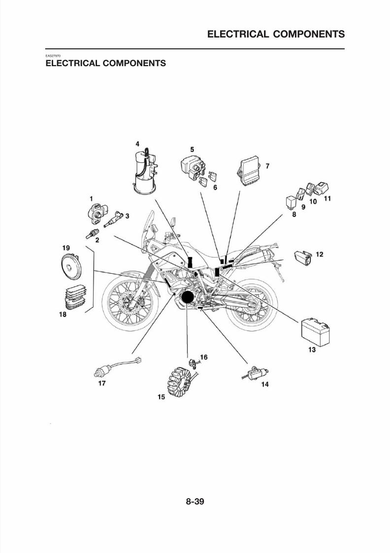
8/12/2019 Yamaha Tenere XT660Z Service Manual
http://slidepdf.com/reader/full/yamaha-tenere-xt660z-service-manual 365/398
ELECTRICAL COMPONENTS
1. Throttle position sensor
2. Coolant temperature sensor
3. Fuel injector
4. Fuel pump
5. Starter relay
6. Main fuse
7. ECU (Electronic Control Unit)8. Turn signal/hazard relay
9. Headlight relay
10. Radiator fan motor relay
11. Relay unit
12 L l t ff it h

8/12/2019 Yamaha Tenere XT660Z Service Manual
http://slidepdf.com/reader/full/yamaha-tenere-xt660z-service-manual 366/398
12. Lean angle cut-off switch
13. Battery
14. Sidestand switch
15. Stator coil
16. Crankshaft position sensor17. O2 sensor
18. Rectifier/regulator
19. Horn
ELECTRICAL COMPONENTS
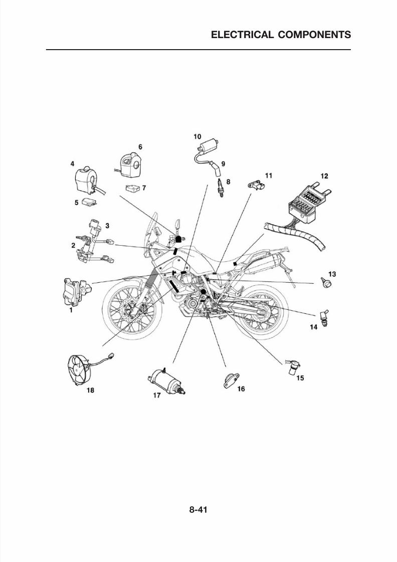
8/12/2019 Yamaha Tenere XT660Z Service Manual
http://slidepdf.com/reader/full/yamaha-tenere-xt660z-service-manual 367/398
ELECTRICAL COMPONENTS
1. Air induction system solenoid
2. Main switch
3. Immobilizer unit
4. Right handlebar switch
5. Front brake light switch
6. Left handlebar switch
7. Clutch switch8. Spark plug
9. Plug cap
10. Ignition coil
11. Intake air pressure sensor
12 Fuse box
8/12/2019 Yamaha Tenere XT660Z Service Manual
http://slidepdf.com/reader/full/yamaha-tenere-xt660z-service-manual 368/398
12. Fuse box
13. Intake air temperature sensor
14. Rear brake light switch
15. Speed sensor
16. Neutral switch
17. Starter motor
18. Radiator fan motor
ELECTRICAL COMPONENTS
EAS27980
CHECKING THE SWITCHES
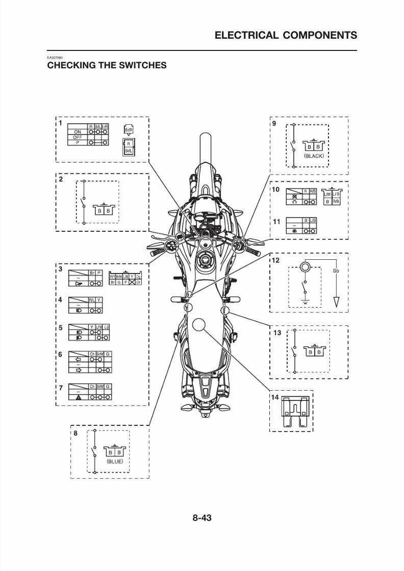
8/12/2019 Yamaha Tenere XT660Z Service Manual
http://slidepdf.com/reader/full/yamaha-tenere-xt660z-service-manual 369/398
8/12/2019 Yamaha Tenere XT660Z Service Manual
http://slidepdf.com/reader/full/yamaha-tenere-xt660z-service-manual 370/398
ELECTRICAL COMPONENTS
Check each switch for continuity with the pocket tester. If the continuity reading is incorrect, checkthe wiring connections and if necessary, replace the switch.
ECA14370
CAUTION:
Never insert the tester probes into the coupler terminal slots “a”. Always insert the probesfrom the opposite end of the coupler, taking care not to loosen or damage the leads.
Pocket tester90890-03112
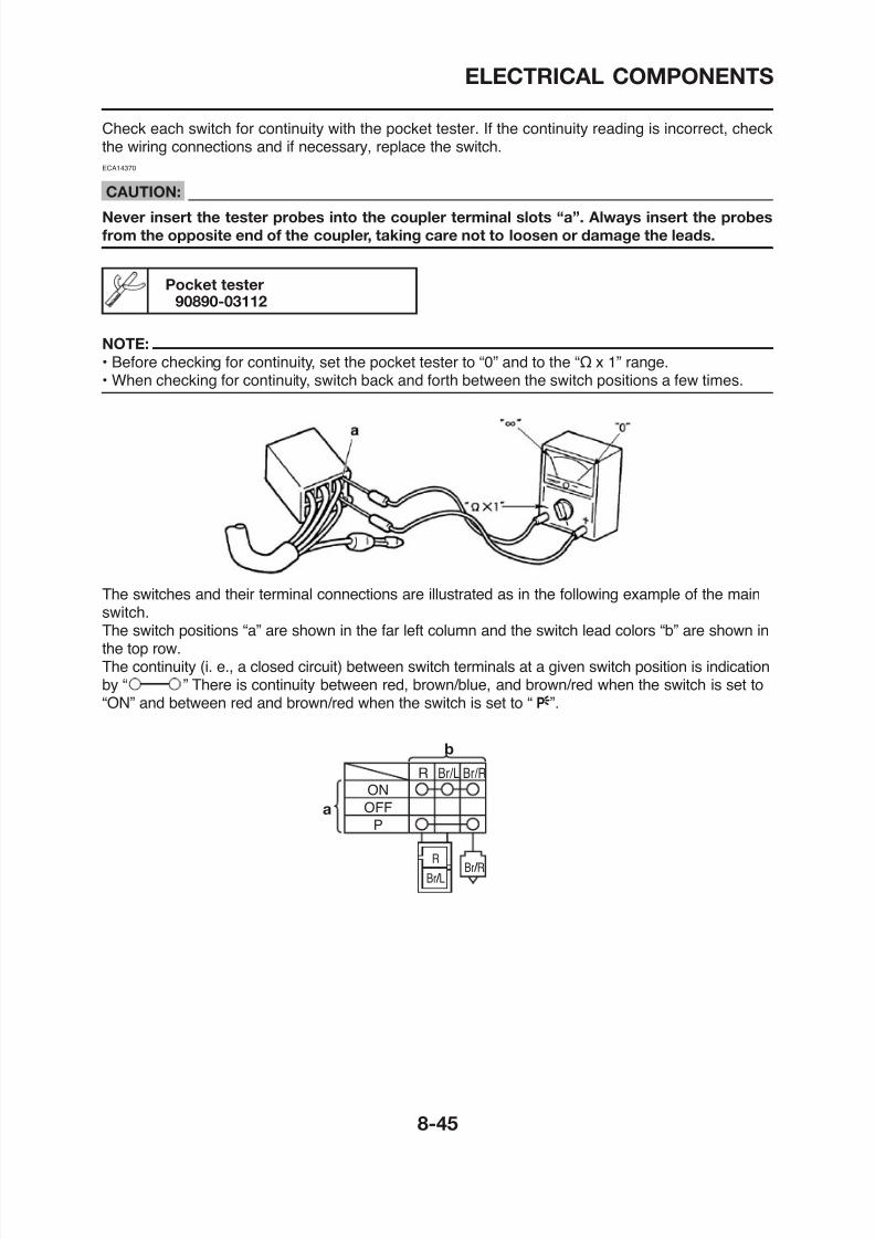
8/12/2019 Yamaha Tenere XT660Z Service Manual
http://slidepdf.com/reader/full/yamaha-tenere-xt660z-service-manual 371/398
90890 03112
NOTE:
• Before checking for continuity, set the pocket tester to “0” and to the “Ω x 1” range.
• When checking for continuity, switch back and forth between the switch positions a few times.
The switches and their terminal connections are illustrated as in the following example of the mainswitch.The switch positions “a” are shown in the far left column and the switch lead colors “b” are shown inthe top row.
ELECTRICAL COMPONENTS
EAS27990
CHECKING THE BULBS AND BULB
SOCKETS
NOTE:
Do not check any of the lights that use LEDs.
Check each bulb and bulb socket for damageor wear, proper connections, and also for conti-nuity between the terminals.Damage/wear → Repair or replace the bulb,
1. Remove:• Bulb
WARNING
Since headlight bulbs get extremely hot,
keep flammable products and your handsaway from them until they have cooled
down.
CAUTION:
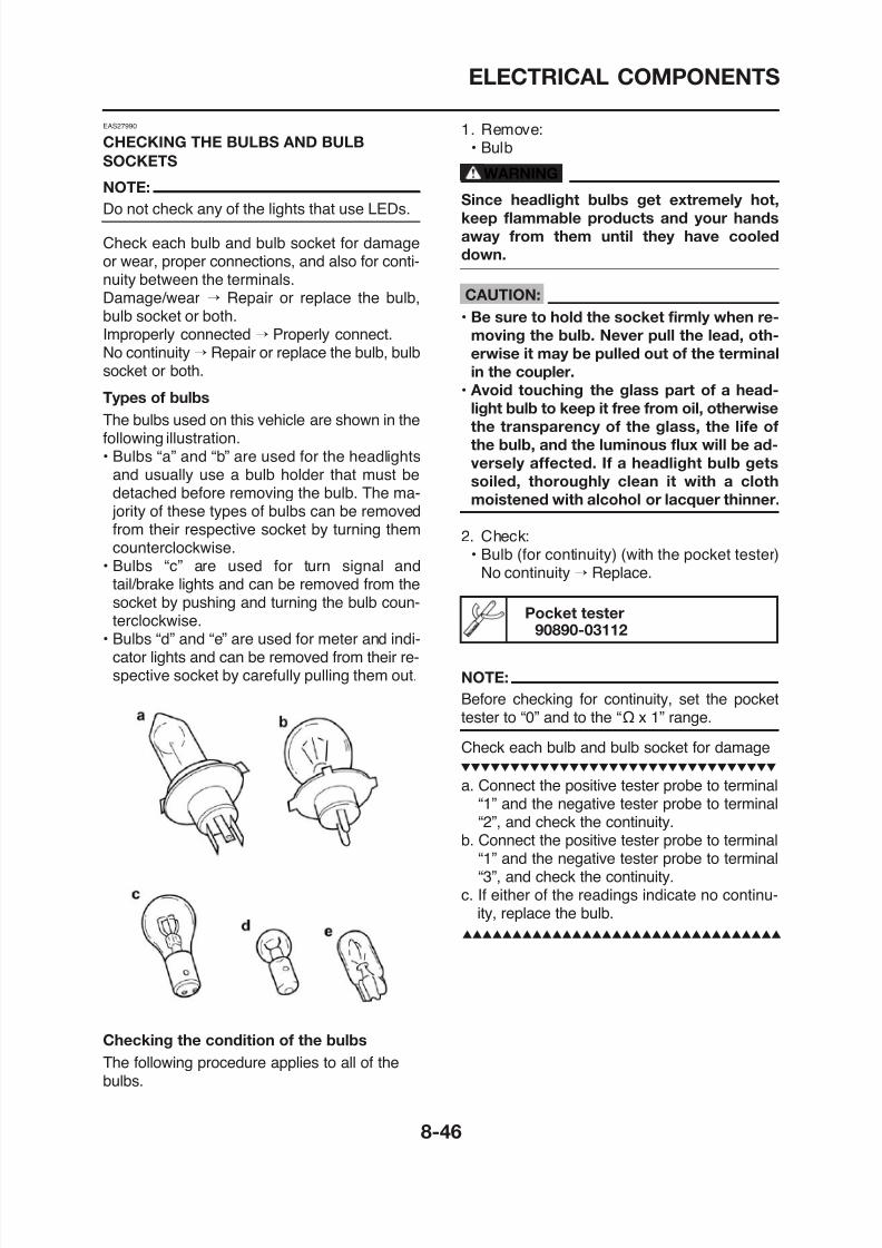
8/12/2019 Yamaha Tenere XT660Z Service Manual
http://slidepdf.com/reader/full/yamaha-tenere-xt660z-service-manual 372/398
bulb socket or both.Improperly connected → Properly connect.No continuity → Repair or replace the bulb, bulb
socket or both.Types of bulbs
The bulbs used on this vehicle are shown in thefollowing illustration.• Bulbs “a” and “b” are used for the headlights
and usually use a bulb holder that must bedetached before removing the bulb. The ma- jority of these types of bulbs can be removed
from their respective socket by turning themcounterclockwise.
• Bulbs “c” are used for turn signal andtail/brake lights and can be removed from thesocket by pushing and turning the bulb coun-terclockwise.
• Bulbs “d” and “e” are used for meter and indi-cator lights and can be removed from their re-
• Be sure to hold the socket firmly when re-
moving the bulb. Never pull the lead, oth-
erwise it may be pulled out of the terminal
in the coupler.• Avoid touching the glass part of a head-
light bulb to keep it free from oil, otherwise
the transparency of the glass, the life of
the bulb, and the luminous flux will be ad-
versely affected. If a headlight bulb gets
soiled, thoroughly clean it with a cloth
moistened with alcohol or lacquer thinner.
2. Check:• Bulb (for continuity) (with the pocket tester)
No continuity → Replace.
Pocket tester90890-03112
ELECTRICAL COMPONENTS
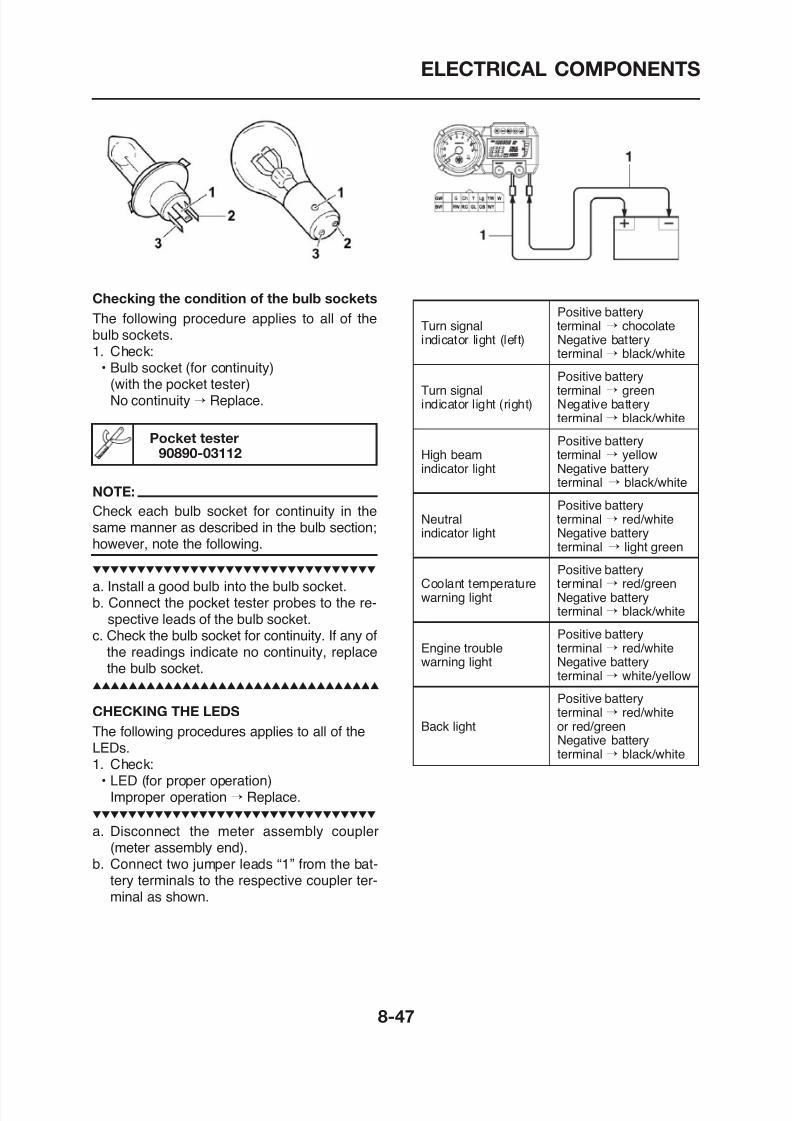
8/12/2019 Yamaha Tenere XT660Z Service Manual
http://slidepdf.com/reader/full/yamaha-tenere-xt660z-service-manual 373/398
Checking the condition of the bulb sockets
The following procedure applies to all of the
bulb sockets.1. Check:• Bulb socket (for continuity)
(with the pocket tester)No continuity → Replace.
NOTE:
Check each bulb socket for continuity in thesame manner as described in the bulb section;however, note the following.
a. Install a good bulb into the bulb socket.
Pocket tester90890-03112
Positive batteryTurn signal terminal → chocolate
indicator light (left) Negative batteryterminal → black/white
Positive batteryTurn signal terminal → greenindicator light (right) Negative battery
terminal → black/white
Positive batteryHigh beam terminal → yellowindicator light Negative battery
terminal → black/white
Positive batteryNeutral terminal → red/whiteindicator light Negative battery
terminal → light green
Positive batteryCoolant temperature terminal → red/green
i li ht N ti b tt
ELECTRICAL COMPONENTS
Immobilizer system indicator LEDConnect the pocket tester (kΩ x 1) to themeter coupler.
Positive tester probe →
black/white ContinuityNegative tester probe →green/blue
Positive tester probe →green/blue No continuity
1. Remove:• Seat
2. Check:• Fuse
a. Connect the pocket tester to the fuse andcheck the continuity.
NOTE:
Set the pocket tester selector to “Ω x 1”.
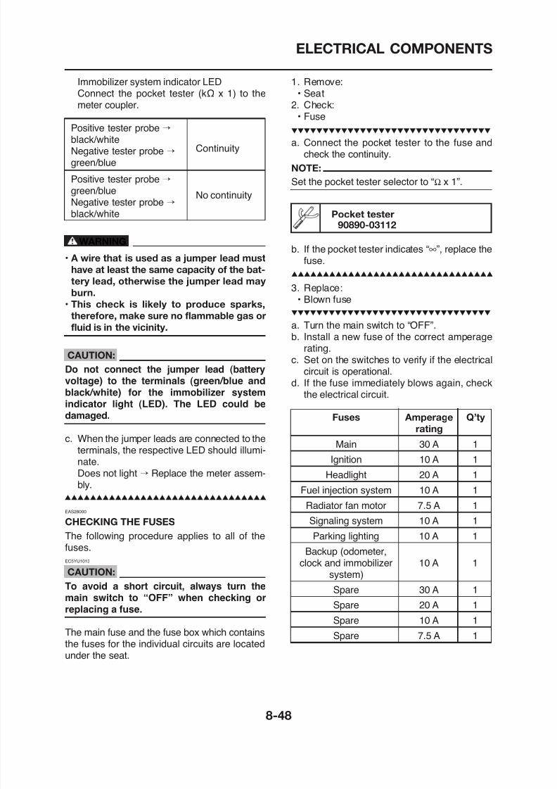
8/12/2019 Yamaha Tenere XT660Z Service Manual
http://slidepdf.com/reader/full/yamaha-tenere-xt660z-service-manual 374/398
g No continuityNegative tester probe →black/white
WARNING
• A wire that is used as a jumper lead must
have at least the same capacity of the bat-
tery lead, otherwise the jumper lead may
burn.
• This check is likely to produce sparks,
therefore, make sure no flammable gas or
fluid is in the vicinity.
CAUTION:
Do not connect the jumper lead (batteryvoltage) to the terminals (green/blue andblack/white) for the immobilizer systemindicator light (LED). The LED could bedamaged.
b. If the pocket tester indicates “∞”, replace thefuse.
3. Replace:• Blown fuse
a. Turn the main switch to “OFF”.
b. Install a new fuse of the correct amperagerating.
c. Set on the switches to verify if the electricalcircuit is operational.
d. If the fuse immediately blows again, checkthe electrical circuit.
Pocket tester90890-03112
Fuses Amperage Q’ty
ELECTRICAL COMPONENTS
WARNING
Never use a fuse with an amperage rating
other than that specified. Improvising or
using a fuse with the wrong amperage rat-
ing may cause extensive damage to the
electrical system, cause the lighting and
ignition systems to malfunction and could
possibly cause a fire.
4 I t ll
ECA13660
CAUTION:
• This is a sealed battery. Never remove the
sealing caps because the balance be-
tween cells will not be maintained and bat-
tery performance will deteriorate.• Charging time, charging amperage and
charging voltage for an MF battery are dif-
ferent from those of conventional batter-
ies. The MF battery should be charged as
explained in the charging method illustra
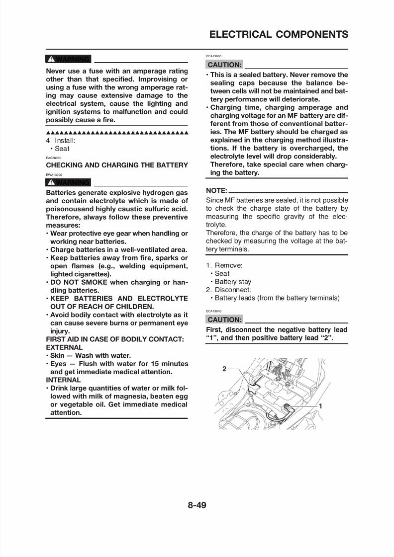
8/12/2019 Yamaha Tenere XT660Z Service Manual
http://slidepdf.com/reader/full/yamaha-tenere-xt660z-service-manual 375/398
4. Install:• Seat
EAS28030
CHECKING AND CHARGING THE BATTERY
EWA13290
WARNING
Batteries generate explosive hydrogen gas
and contain electrolyte which is made of
poisonousand highly caustic sulfuric acid.
Therefore, always follow these preventive
measures:
• Wear protective eye gear when handling or
working near batteries.
• Charge batteries in a well-ventilated area.
• Keep batteries away from fire, sparks or
open flames (e.g., welding equipment,
lighted cigarettes).
• DO NOT SMOKE when charging or han-
dling batteries.
explained in the charging method illustra-
tions. If the battery is overcharged, the
electrolyte level will drop considerably.
Therefore, take special care when charg-
ing the battery.
NOTE:
Since MF batteries are sealed, it is not possibleto check the charge state of the battery bymeasuring the specific gravity of the elec-trolyte.Therefore, the charge of the battery has to bechecked by measuring the voltage at the bat-tery terminals.
1. Remove:• Seat• Battery stay
2. Disconnect:B l d (f h b i l )
ELECTRICAL COMPONENTS
3. Remove:• Battery
4. Check:• Battery charge
a. Connect a pocket tester to the battery termi-nals.
• Positive tester probe→positive battery terminalN ti t t b
• To reduce the chance of sparks, do not
plug in the battery charger until the battery
charger leads are connected to the bat-
tery.
• Before removing the battery charger lead
clips from the battery terminals, be sure toturn off the battery charger.
• Make sure the battery charger lead clips
are in full contact with the battery terminal
and that they are not shorted. A corroded
b tt h l d li t
8/12/2019 Yamaha Tenere XT660Z Service Manual
http://slidepdf.com/reader/full/yamaha-tenere-xt660z-service-manual 376/398
• Negative tester probe →negative battery terminal
NOTE:• The charge state of an MF battery can be
checked by measuring its open-circuit voltage(i.e., the voltage when the positive battery ter-minal is disconnected).
• No charging is necessary when the open-cir-cuit voltage equals or exceeds 12.8 V.
b. Check the charge of the battery, as shown in
the charts and the following example.
ExampleOpen-circuit voltage = 12.0 VCharging time = 6.5 hoursCharge of the battery = 20–30%
battery charger lead clip may generate
heat in the contact area and a weak clip
spring may cause sparks.
• If the battery becomes hot to the touch at
any time during the charging process, dis-
connect the battery charger and let the bat
tery cool before reconnecting it. Hot bat-
teries can explode!
• As shown in the following illustration, the
open-circuit voltage of an MF battery sta-
bilizes about 30 minutes after charging has
been completed. Therefore, wait 30 min-
utes after charging is completed beforemeasuring the open-circuit voltage.
Charging method using a variable-current
(voltage) charger
a. Measure the open-circuit voltage prior tocharging
ELECTRICAL COMPONENTS
• Standard charging current is reachedBattery is good.
• Standard charging current is not reachedReplace the battery.
d. Adjust the voltage so that the current is atthe standard charging level.
e. Set the time according to the charging timesuitable for the open-circuit voltage.Refer to “Battery condition checking steps”
12.8 V or more --- Charging is complete.12.7 V or less --- Recharging is required.Under 12.0 V --- Replace the battery.
6. Install:• Battery
7. Connect:• Battery leads
(to the battery terminals)
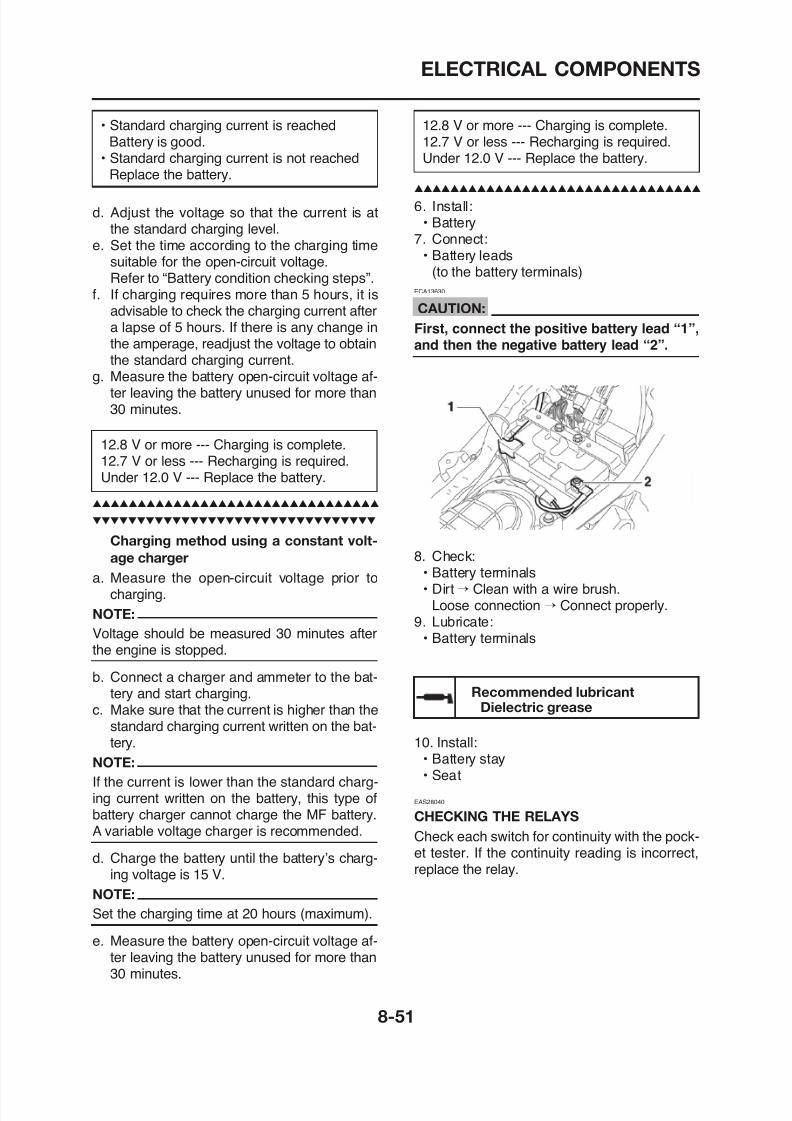
8/12/2019 Yamaha Tenere XT660Z Service Manual
http://slidepdf.com/reader/full/yamaha-tenere-xt660z-service-manual 377/398
Refer to Battery condition checking steps .f. If charging requires more than 5 hours, it is
advisable to check the charging current aftera lapse of 5 hours. If there is any change in
the amperage, readjust the voltage to obtainthe standard charging current.
g. Measure the battery open-circuit voltage af-ter leaving the battery unused for more than30 minutes.
12.8 V or more --- Charging is complete.12.7 V or less --- Recharging is required.
Under 12.0 V --- Replace the battery.
Charging method using a constant volt-
age charger
a. Measure the open-circuit voltage prior tocharging
ECA13630
CAUTION:
First, connect the positive battery lead “1”,
and then the negative battery lead “2”.
8. Check:• Battery terminals• Dirt→ Clean with a wire brush.
ELECTRICAL COMPONENTS
Pocket tester90890-03112
1. Disconnect the relay from the wire harness.2. Connect the pocket tester (Ω x 1) and bat-
tery (12 V) to the relay terminal as shown.Check the relay operation.Out of specification → Replace.
Starter relay
Fuel injection system relay
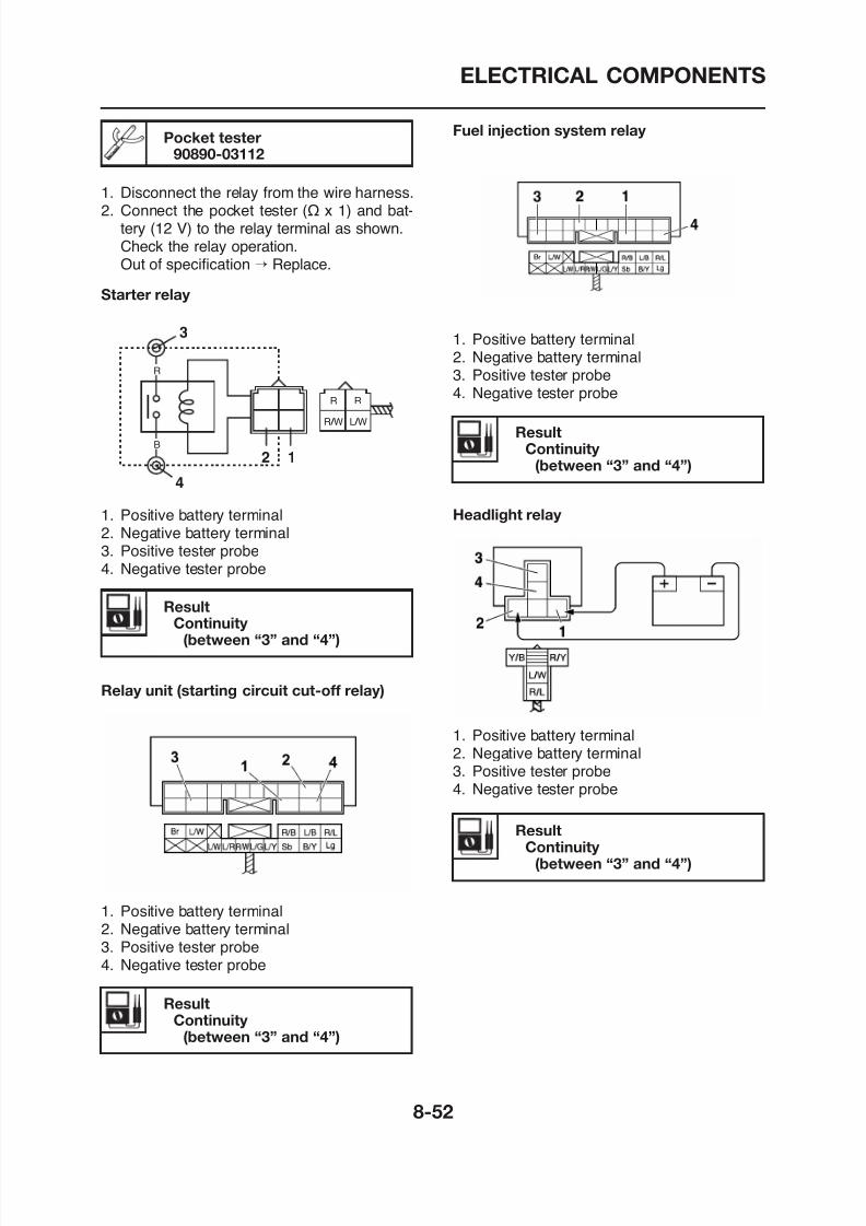
8/12/2019 Yamaha Tenere XT660Z Service Manual
http://slidepdf.com/reader/full/yamaha-tenere-xt660z-service-manual 378/398
1. Positive battery terminal2. Negative battery terminal3. Positive tester probe4. Negative tester probe
R
B
R R
R / W L / W
3
4
2 1
ResultContinuity
(between “3” and “4”)
Headlight relay
1. Positive battery terminal2. Negative battery terminal
3. Positive tester probe4. Negative tester probe
ResultContinuity
(between “3” and “4”)
ELECTRICAL COMPONENTS
Radiator fan motor relay
2. Check:
• Turn signal/hazard relay output voltageOut of specification → Replace.
Turn signal/hazard relay outputvoltage
b. Turn the main switch to “ON”.c. Measure the turn signal/hazard relay input
voltage.
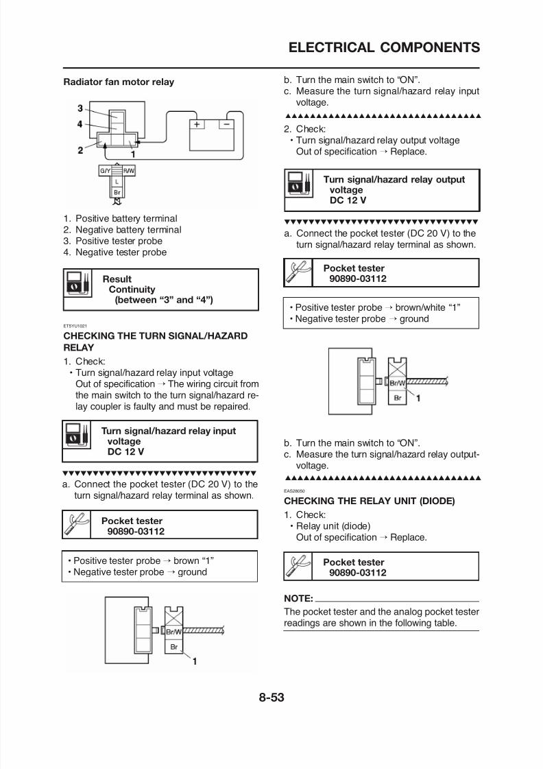
8/12/2019 Yamaha Tenere XT660Z Service Manual
http://slidepdf.com/reader/full/yamaha-tenere-xt660z-service-manual 379/398
ResultContinuity
(between “3” and “4”)
ET5YU1021
CHECKING THE TURN SIGNAL/HAZARD
RELAY
1. Check:• Turn signal/hazard relay input voltage
Out of specification → The wiring circuit fromthe main switch to the turn signal/hazard re-lay coupler is faulty and must be repaired
gDC 12 V
a. Connect the pocket tester (DC 20 V) to theturn signal/hazard relay terminal as shown.
Pocket tester90890-03112
• Positive tester probe→ brown/white “1”• Negative tester probe → ground
1. Positive battery terminal
2. Negative battery terminal3. Positive tester probe4. Negative tester probe
ELECTRICAL COMPONENTS
EAS28070
CHECKING THE SPARK PLUG CAP
1. Check:• Spark plug cap resistance
Out of specification → Replace.
Resistance10.0 kΩ at 20 °C (68 °F)
a. Remove the spark plug cap from the spark
Continuity Positive tester probe →sky blue “1”Negative tester probe →black/yellow “2”
No continuity Positive tester probe →black/yellow “2”Negative tester probe →sky blue “1”
Continuity Positive tester probe →
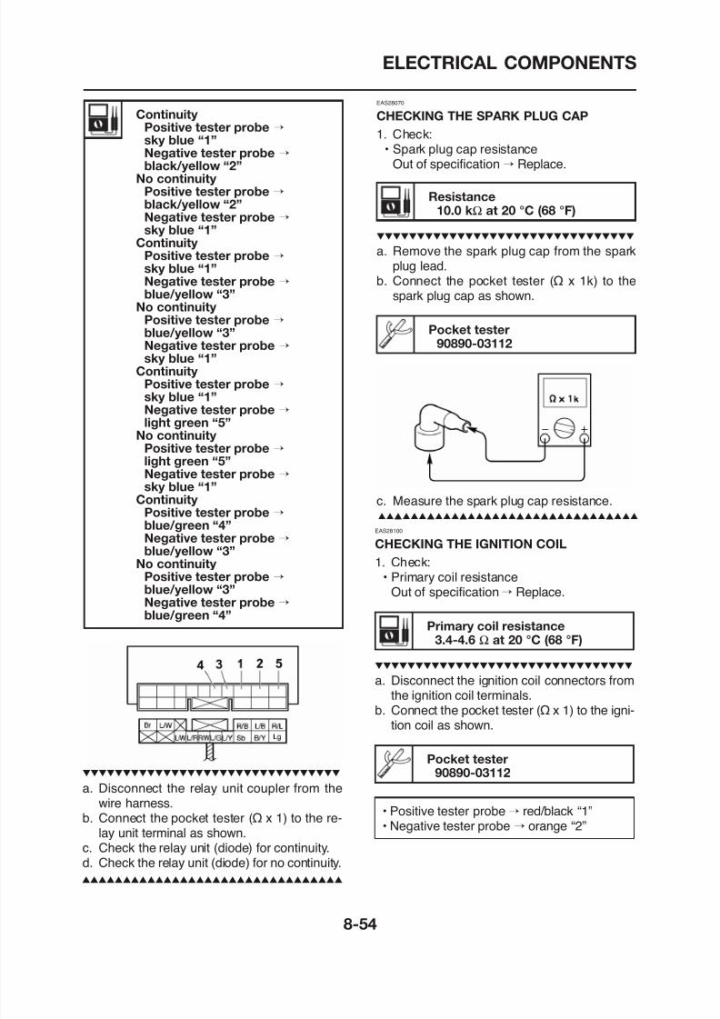
8/12/2019 Yamaha Tenere XT660Z Service Manual
http://slidepdf.com/reader/full/yamaha-tenere-xt660z-service-manual 380/398
p p g p pplug lead.
b. Connect the pocket tester (Ω x 1k) to thespark plug cap as shown.
Pocket tester90890-03112
c. Measure the spark plug cap resistance.
EAS28100
CHECKING THE IGNITION COIL
Positive tester probe →sky blue “1”Negative tester probe →blue/yellow “3”
No continuity Positive tester probe →blue/yellow “3”Negative tester probe →sky blue “1”
Continuity Positive tester probe →sky blue “1”Negative tester probe →light green “5”
No continuity Positive tester probe →light green “5”Negative tester probe →sky blue “1”
Continuity Positive tester probe →blue/green “4”Negative tester probe →
ELECTRICAL COMPONENTS
c. Measure the primary coil resistance.
a. Disconnect the spark plug cap “2” from thespark plug.
b C h h “ h
Minimum ignition spark gap6.0 mm (0.24 in)
NOTE:
If the ignition spark gap is within specification,the ignition system circuit is operating normally.
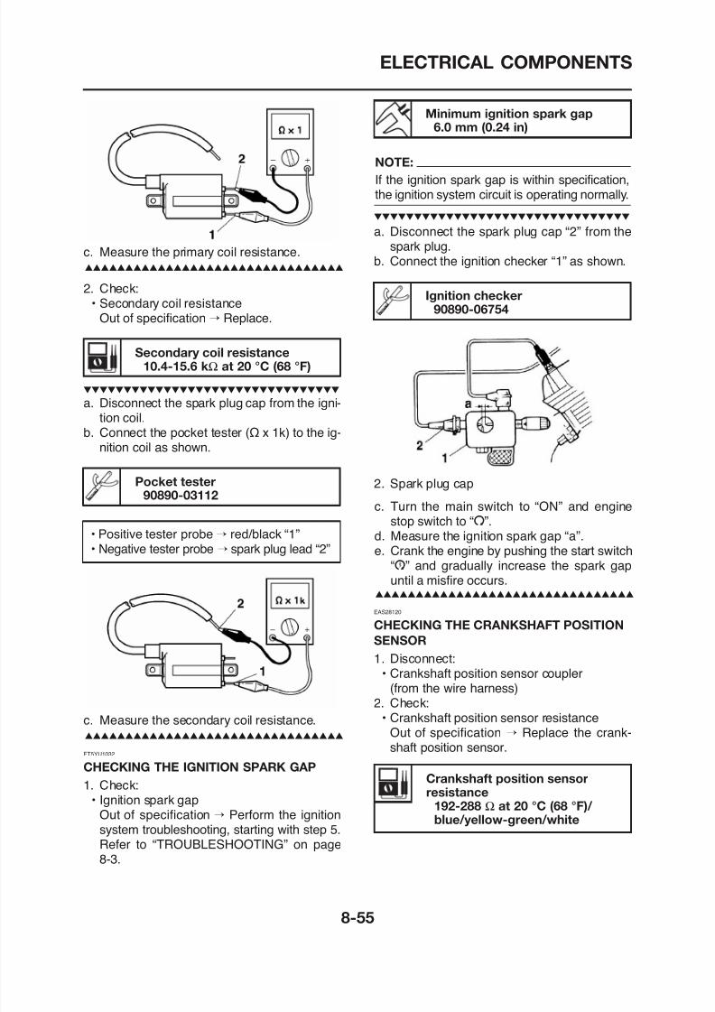
8/12/2019 Yamaha Tenere XT660Z Service Manual
http://slidepdf.com/reader/full/yamaha-tenere-xt660z-service-manual 381/398
2. Check:
• Secondary coil resistanceOut of specification → Replace.
c easu e t e p a y co es sta ce
Secondary coil resistance10.4-15.6 kΩ at 20 °C (68 °F)
a. Disconnect the spark plug cap from the igni-tion coil.
b. Connect the pocket tester (Ω x 1k) to the ig-nition coil as shown.
Pocket tester90890-03112
• Positive tester probe→ red/black “1”
b. Connect the ignition checker “1” as shown.
Ignition checker
90890-06754
2. Spark plug cap
c. Turn the main switch to “ON” and enginestop switch to “I”.
d Measure the ignition spark gap “a”
ELECTRICAL COMPONENTS
c. Turn the lean angle cut-off switch to 65°.
a. Connect the pocket tester (Ω x 100) tothe crankshaft position sensor coupler asshown.
Pocket tester90890-03112
• Positive tester probe → blue/yellow “1”• Negative tester probe → green/white “2”
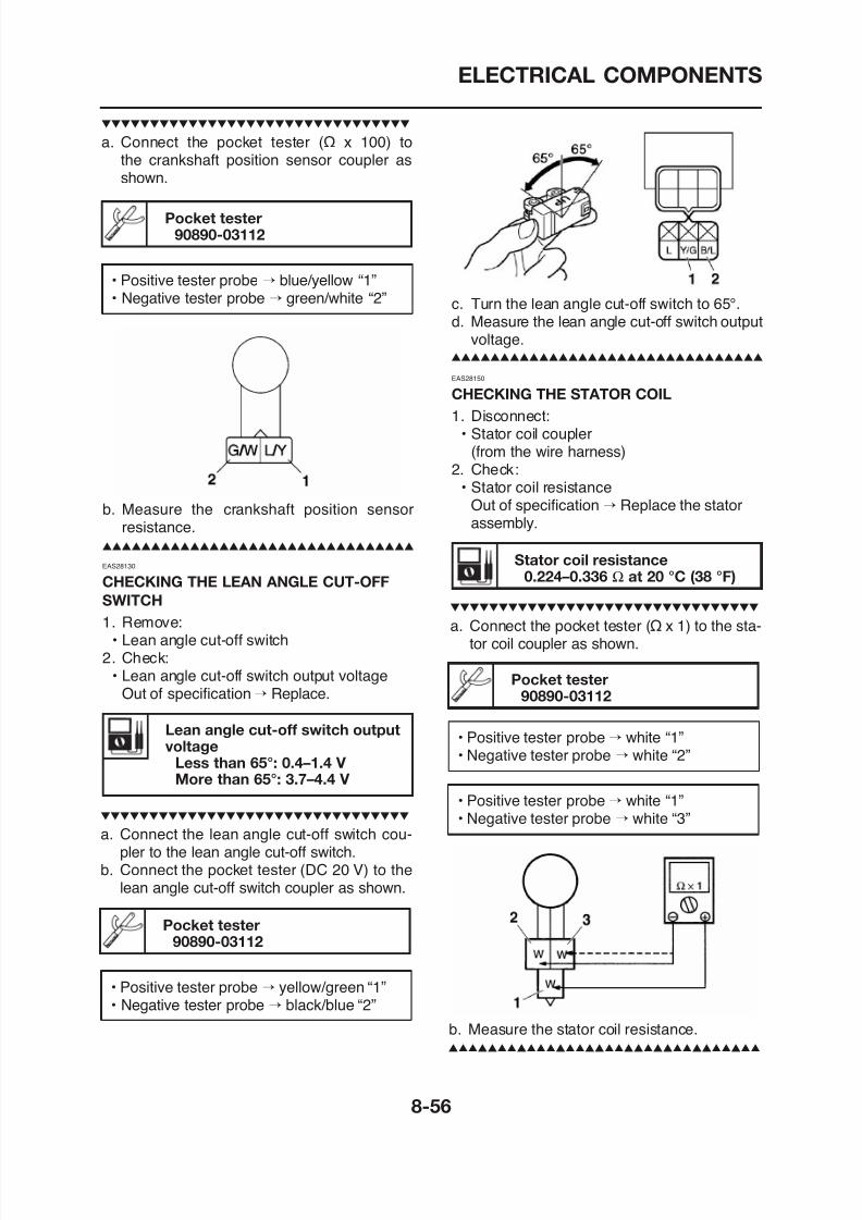
8/12/2019 Yamaha Tenere XT660Z Service Manual
http://slidepdf.com/reader/full/yamaha-tenere-xt660z-service-manual 382/398
EAS28130
CHECKING THE LEAN ANGLE CUT-OFF
SWITCH
1. Remove:• Lean angle cut-off switch
gd. Measure the lean angle cut-off switch output
voltage.
Stator coil resistance0.224–0.336 Ω at 20 °C (38 °F)
EAS28150
CHECKING THE STATOR COIL
1. Disconnect:• Stator coil coupler
(from the wire harness)2. Check:
• Stator coil resistanceOut of specification → Replace the stator
assembly.
a. Connect the pocket tester (Ω x 1) to the sta-tor coil coupler as shown
b. Measure the crankshaft position sensor
resistance.
ELECTRICAL COMPONENTS
Coil resistance1.15–1.25 Ω at 20 °C (68 °F)
EAS28180
CHECKING THE HORN
1. Check:• Horn resistance
Out of specification→Replace.
a. Disconnect the horn leads from the horn ter-
a. Disconnect the horn leads from the horn ter-
minals.b. Connect a battery (12 V) to the horn termi-
nals.
3. Check:• Horn sound
Faulty sound → Replace the horn.
EAS28210
CHECKING THE COOLANT
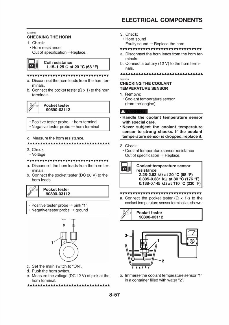
8/12/2019 Yamaha Tenere XT660Z Service Manual
http://slidepdf.com/reader/full/yamaha-tenere-xt660z-service-manual 383/398
minals.b. Connect the pocket tester (Ω x 1) to the horn
terminals.
Pocket tester90890-03112
• Positive tester probe → horn terminal• Negative tester probe→ horn terminal
c. Measure the horn resistance.
2. Check:• Voltage
a. Disconnect the horn leads from the horn ter-minals.
CHECKING THE COOLANT
TEMPERATURE SENSOR
1. Remove:
• Coolant temperature sensor(from the engine)
WARNING
• Handle the coolant temperature sensor
with special care.
• Never subject the coolant temperature
sensor to strong shocks. If the coolant
temperature sensor is dropped, replace it.
2. Check:• Coolant temperature sensor resistance
Out of specification → Replace.
Coolant temperature sensorresistance
ELECTRICAL COMPONENTS
3 Install:
• Positive tester probe→ green/white “1”• Negative tester probe → black “2”
NOTE:
Make sure that the coolant temperature sensorterminals do not get wet.
c. Place a thermometer “3” in the water.
d. Slowly heat the water, then let it cool downto the specified temperature.
e. Measure the coolant temperature sensor re-sistance.
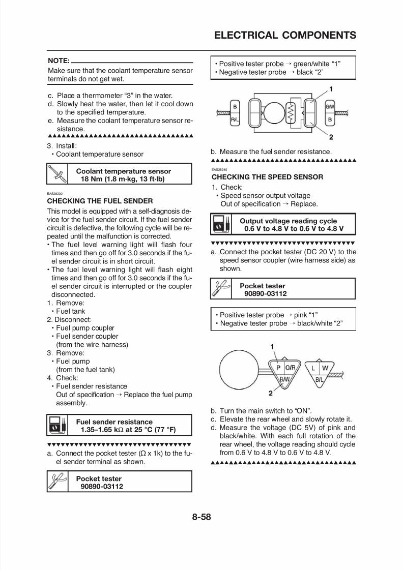
8/12/2019 Yamaha Tenere XT660Z Service Manual
http://slidepdf.com/reader/full/yamaha-tenere-xt660z-service-manual 384/398
3. Install:• Coolant temperature sensor
Coolant temperature sensor18 Nm (1.8 m·kg, 13 ft·lb)
EAS28230
CHECKING THE FUEL SENDER
This model is equipped with a self-diagnosis de-vice for the fuel sender circuit. If the fuel sendercircuit is defective, the following cycle will be re-peated until the malfunction is corrected.
• The fuel level warning light will flash fourtimes and then go off for 3.0 seconds if the fu-el sender circuit is in short circuit.
• The fuel level warning light will flash eighttimes and then go off for 3.0 seconds if the fu-el sender circuit is interrupted or the couplerdisconnected.
1 Remove:
b. Measure the fuel sender resistance.
Output voltage reading cycle0.6 V to 4.8 V to 0.6 V to 4.8 V
EAS28240
CHECKING THE SPEED SENSOR
1. Check:• Speed sensor output voltage
Out of specification → Replace.
a. Connect the pocket tester (DC 20 V) to thespeed sensor coupler (wire harness side) asshown.
Pocket tester90890-03112
ELECTRICAL COMPONENTS
EAS28300
CHECKING THE THROTTLE POSITION
SENSOR
1. Remove:• Throttle position sensor
(from the throttle body)2. Check:• Throttle position sensor maximum resistance
Out of specification → Replace the throttleposition sensor.
• Stop the engine before refueling.
• Do not smoke, and keep away from open
flames, sparks, or any other source of fire.
• If you do accidentally spill gasoline, wipe it
up immediately with dry rags.
• If gasoline touches the engine when it ishot, a fire may occur. Therefore, make sure
the engine is completely cool before per-
forming the following test.
1 R
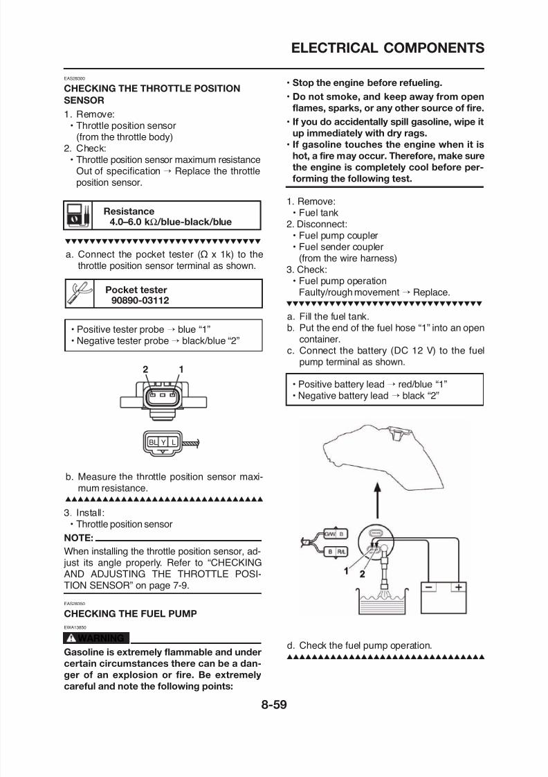
8/12/2019 Yamaha Tenere XT660Z Service Manual
http://slidepdf.com/reader/full/yamaha-tenere-xt660z-service-manual 385/398
Resistance4.0–6.0 kΩ/blue-black/blue
a. Connect the pocket tester (Ω x 1k) to thethrottle position sensor terminal as shown.
Pocket tester90890-03112
• Positive tester probe→
blue “1”• Negative tester probe→ black/blue “2”
2 1
1. Remove:• Fuel tank
2. Disconnect:
• Fuel pump coupler• Fuel sender coupler
(from the wire harness)3. Check:
• Fuel pump operationFaulty/rough movement → Replace.
a. Fill the fuel tank.b. Put the end of the fuel hose “1” into an open
container.c. Connect the battery (DC 12 V) to the fuel
pump terminal as shown.
• Positive battery lead → red/blue “1”• Negative battery lead → black “2”
ELECTRICAL COMPONENTS
Intake pressure sensor outputvoltage3.4-3.8 V
Intake air temperature sensorresistance
2.21-2.69 Ω at 20 °C (68 °F)
a. Connect the pocket tester (Ω x 100) to theintake air temperature sensor terminal asshown.
Pocket tester90890-03112
EAS28410
CHECKING THE INTAKE AIR PRESSURE
SENSOR
1. Check:• Intake air pressure sensor output voltage
Out of specification→
Replace.
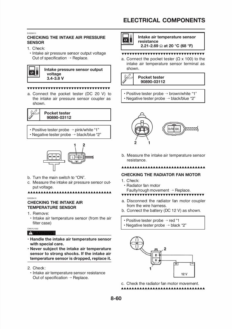
8/12/2019 Yamaha Tenere XT660Z Service Manual
http://slidepdf.com/reader/full/yamaha-tenere-xt660z-service-manual 386/398
a. Connect the pocket tester (DC 20 V) to
the intake air pressure sensor coupler asshown.
Pocket tester90890-03112
• Positive tester probe → pink/white “1”• Negative tester probe → black/blue “2”
L B / LP / W
1 2
• Positive tester probe→ brown/white “1”
• Negative tester probe→
black/blue “2”
b. Measure the intake air temperature sensorresistance.
Br / W B / L
2 1
CHECKING THE RADIATOR FAN MOTOR
ELECTRICAL COMPONENTS
CHECKING THE STARTER MOTOR
1. Check:• Starter motor
a. Connect the positive battery terminal “1” and
starter motor lead “2” with a jumper lead “3”.
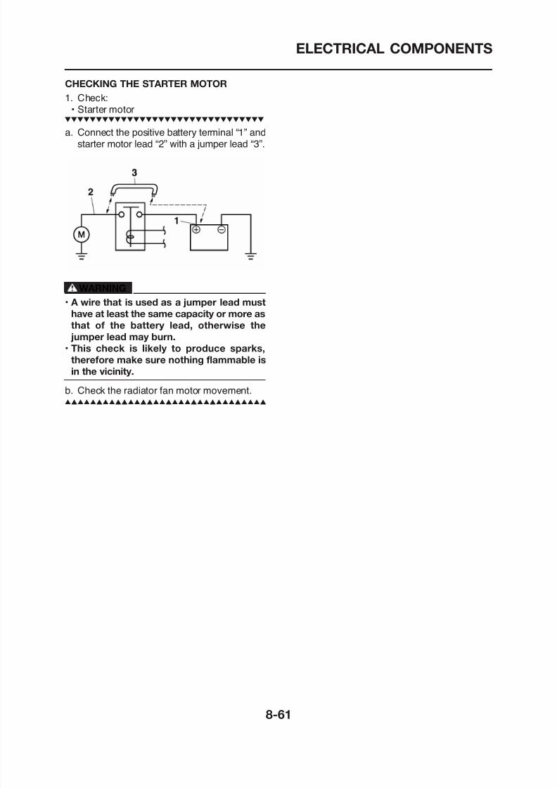
8/12/2019 Yamaha Tenere XT660Z Service Manual
http://slidepdf.com/reader/full/yamaha-tenere-xt660z-service-manual 387/398
WARNING
• A wire that is used as a jumper lead must
have at least the same capacity or more as
that of the battery lead, otherwise the
jumper lead may burn.• This check is likely to produce sparks,
therefore make sure nothing flammable is
in the vicinity.
b. Check the radiator fan motor movement.

8/12/2019 Yamaha Tenere XT660Z Service Manual
http://slidepdf.com/reader/full/yamaha-tenere-xt660z-service-manual 388/398
TROUBLESHOOTING
TROUBLESHOOTING.................................................................................... 9-1GENERAL INFORMATION ...................................................................... 9-1
STARTING FAILURES ............................................................................. 9-1INCORRECT ENGINE IDLING SPEED................................................... 9-1POOR MEDIUM-AND-HIGH-SPEED PERFORMANCE.......................... 9-2FAULTY GEAR SHIFTING....................................................................... 9-2FAULTY CLUTCH..................................................................................... 9-2OVERHEATING........................................................................................ 9-3
8/12/2019 Yamaha Tenere XT660Z Service Manual
http://slidepdf.com/reader/full/yamaha-tenere-xt660z-service-manual 389/398
OVERHEATING........................................................................................ 9 3OVERCOOLING....................................................................................... 9-3POOR BRAKING PERFORMANCE......................................................... 9-3FAULTY FRONT FORK LEGS................................................................. 9-3UNSTABLE HANDLING........................................................................... 9-3FAULTY LIGHTING OR SIGNALING SYSTEM....................................... 9-4

8/12/2019 Yamaha Tenere XT660Z Service Manual
http://slidepdf.com/reader/full/yamaha-tenere-xt660z-service-manual 390/398
TROUBLESHOOTING
EAS28450
TROUBLESHOOTING
EAS28460
GENERAL INFORMATION
NOTE:
The following guide for troubleshooting doesnot cover all the possible causes of trouble. Itshould be helpful, however, as a guide to basictroubleshooting. Refer to the relative procedurein this manual for checks, adjustments, and re-
Electrical system
1. Battery• Discharged battery• Faulty battery
2. Fuse(s)
• Blown, damaged or incorrect fuse• Improperly installed fuse3. Spark plug
• Incorrect spark plug gap• Incorrect spark plug heat range• Fouled spark plug
W d d l d
8/12/2019 Yamaha Tenere XT660Z Service Manual
http://slidepdf.com/reader/full/yamaha-tenere-xt660z-service-manual 391/398
placement of parts.
EAS28470
STARTING FAILURESEngine
1. Cylinder and cylinder head• Loose spark plug• Loose cylinder head or cylinder• Damaged cylinder head gasket• Damaged cylinder gasket• Worn or damaged cylinder
• Incorrect valve clearance• Improperly sealed valve• Incorrect valve-to-valve-seat contact• Incorrect valve timing• Faulty valve spring• Seized valve
2. Piston and piston ring(s)• Improperly installed piston ring
• Worn or damaged electrode• Worn or damaged insulator• Faulty spark plug cap
4. Ignition coil• Cracked or broken ignition coil body• Broken or shorted primary or secondary coils• Faulty spark plug lead
5. Ignition system• Faulty ECU• Faulty crankshaft position sensor• Broken A.C. magneto rotor woodruff key
6. Switches and wiring• Faulty main switch• Faulty engine stop switch• Broken or shorted wiring• Faulty neutral switch• Faulty start switch• Faulty sidestand switch• Faulty clutch switch
TROUBLESHOOTING
Electrical system
1. Battery• Discharged battery• Faulty battery
2. Spark plug
• Incorrect spark plug gap• Incorrect spark plug heat range• Fouled spark plug• Worn or damaged electrode• Worn or damaged insulator• Faulty spark plug cap
3 I iti il
EAS28550
JUMPS OUT OF GEAR
Shift shaft
• Incorrect shift pedal position• Improperly returned stopper lever
Shift forks
• Worn shift fork
Shift drum
• Incorrect axial play• Worn shift drum groove
8/12/2019 Yamaha Tenere XT660Z Service Manual
http://slidepdf.com/reader/full/yamaha-tenere-xt660z-service-manual 392/398
3. Ignition coil• Broken or shorted primary or secondary
coils
• Faulty spark plug lead• Cracked or broken ignition coil
4. Ignition system• Faulty ECU• Faulty crankshaft position sensor• Broken A.C. magneto rotor woodruff key
EAS28510
POOR MEDIUM AND HIGH-SPEED
PERFORMANCERefer to “STARTING FAILURES” on page 9-1.
Engine
1. Air filter• Clogged air filter element
Fuel system
Worn shift drum groove
Transmission
• Worn gear dog
EAS28570
FAULTY CLUTCH
Clutch slips
1. Clutch• Improperly assembled clutch• Improperly adjusted clutch cable• Loose or fatigued clutch spring
• Worn friction plate• Worn clutch plate
2. Engine oil• Incorrect oil level• Incorrect oil viscosity (low)• Deteriorated oil
Clutch drags
TROUBLESHOOTING
EAS28590
OVERHEATING
Engine
1. Clogged coolant passages2. Cylinder head and piston
• Heavy carbon buildup3. Engine oil
• Incorrect oil level• Incorrect oil viscosity• Inferior oil quality
C li t
EAS28620
POOR BRAKING PERFORMANCE
• Worn brake pad• Worn brake disc• Air in hydraulic brake system• Leaking brake fluid
• Faulty brake caliper seal• Loose union bolt• Damaged brake hose• Oil or grease on the brake disc• Oil or grease on the brake pad• Incorrect brake fluid level
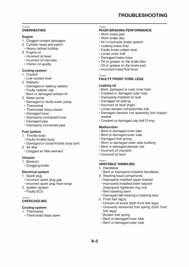
8/12/2019 Yamaha Tenere XT660Z Service Manual
http://slidepdf.com/reader/full/yamaha-tenere-xt660z-service-manual 393/398
Cooling system
1. Coolant• Low coolant level
2. Radiator• Damaged or leaking radiator• Faulty radiator cap• Bent or damaged radiator fin
3. Water pump• Damaged or faulty water pump• Thermostat• Thermostat stays closed
• Damaged hose• Improperly connected hose• Damaged pipe• Improperly connected pipe
Fuel system
1. Throttle body• Faulty throttle body
Incorrect brake fluid level
EAS28660
FAULTY FRONT FORK LEGS
Leaking oil
• Bent, damaged or rusty inner tube• Cracked or damaged outer tube• Improperly installed oil seal• Damaged oil seal lip• Incorrect oil level (high)• Loose damper rod assembly bolt• Damaged damper rod assembly bolt copper
washer• Cracked or damaged cap bolt O-ring
Malfunction
• Bent or damaged inner tube• Bent or damaged outer tube• Damaged fork spring
W d d t t b b hi
TROUBLESHOOTING
4. Swingarm• Worn bearing or bushing• Bent or damaged swingarm
5. Rear shock absorber assembly• Faulty rear shock absorber spring• Leaking oil or gas
6. Tire(s)• Uneven tire pressures (front and rear)• Incorrect tire pressure• Uneven tire wear
7. Wheel(s)I t h l b l
Turn signal does not come on
• Faulty turn signal switch• Faulty turn signal/hazard relay• Burnt-out turn signal bulb• Incorrect connection• Damaged or faulty wire harness• Improperly grounded circuit• Faulty battery• Blown, damaged or incorrect fuse
Turn signal flashes slowly
• Faulty turn signal/hazard relay
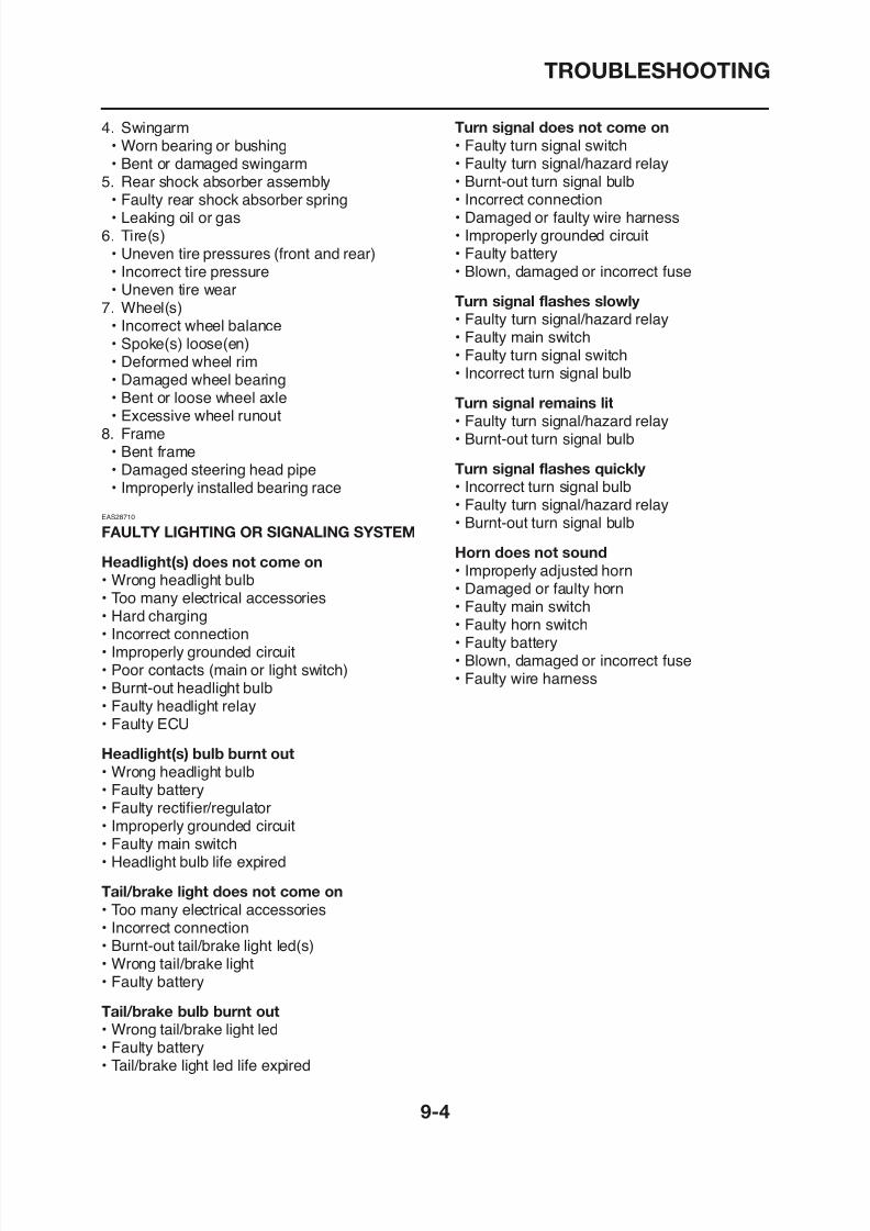
8/12/2019 Yamaha Tenere XT660Z Service Manual
http://slidepdf.com/reader/full/yamaha-tenere-xt660z-service-manual 394/398
• Incorrect wheel balance• Spoke(s) loose(en)• Deformed wheel rim
• Damaged wheel bearing• Bent or loose wheel axle• Excessive wheel runout
8. Frame• Bent frame• Damaged steering head pipe• Improperly installed bearing race
EAS28710
FAULTY LIGHTING OR SIGNALING SYSTEM
Headlight(s) does not come on
• Wrong headlight bulb• Too many electrical accessories• Hard charging• Incorrect connection• Improperly grounded circuit
Faulty turn signal/hazard relay• Faulty main switch• Faulty turn signal switch
• Incorrect turn signal bulb
Turn signal remains lit
• Faulty turn signal/hazard relay• Burnt-out turn signal bulb
Turn signal flashes quickly
• Incorrect turn signal bulb• Faulty turn signal/hazard relay
• Burnt-out turn signal bulbHorn does not sound
• Improperly adjusted horn• Damaged or faulty horn• Faulty main switch• Faulty horn switch• Faulty battery
WIRING DIAGRAM
XT660Z 2008
1. Crankshaft position sensor
2. A.C. magneto
3. Neutral switch
4. Main switch5. Rectifier/regulator
6. Wire plus lead
7. Battery
8. Main fuse
9. Starter relay
10. Starter motor
37. Engine trouble warning light
38. Fuel pump
39. Sidestand switch
40. Front brake light switch
41. Start switch
42. Engine stop switch
43. Right handlebar switch44. Headlight relay
45. Turn signal/hazard relay
46. Clutch switch
47. Hazard switch
48. Turn signal switch
49 Dimmer switch
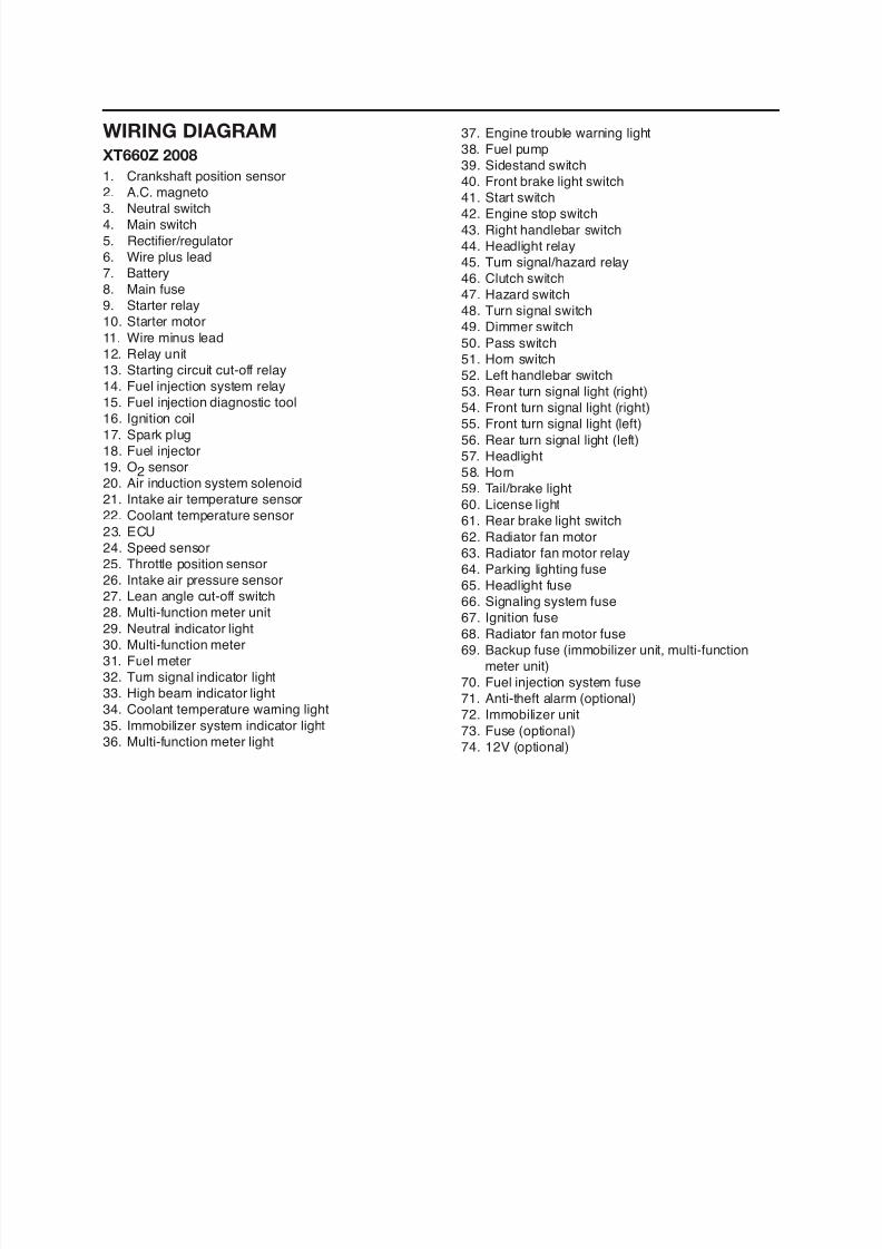
8/12/2019 Yamaha Tenere XT660Z Service Manual
http://slidepdf.com/reader/full/yamaha-tenere-xt660z-service-manual 395/398
11. Wire minus lead
12. Relay unit
13. Starting circuit cut-off relay
14. Fuel injection system relay15. Fuel injection diagnostic tool
16. Ignition coil
17. Spark plug
18. Fuel injector
19. O2 sensor
20. Air induction system solenoid
21. Intake air temperature sensor
22. Coolant temperature sensor
23. ECU24. Speed sensor
25. Throttle position sensor
26. Intake air pressure sensor
27. Lean angle cut-off switch
28. Multi-function meter unit
29. Neutral indicator light
30. Multi-function meter
31 Fuel meter
49. Dimmer switch
50. Pass switch
51. Horn switch
52. Left handlebar switch
53. Rear turn signal light (right)
54. Front turn signal light (right)
55. Front turn signal light (left)
56. Rear turn signal light (left)
57. Headlight
58. Horn
59. Tail/brake light
60. License light
61. Rear brake light switch
62. Radiator fan motor63. Radiator fan motor relay
64. Parking lighting fuse
65. Headlight fuse
66. Signaling system fuse
67. Ignition fuse
68. Radiator fan motor fuse
69. Backup fuse (immobilizer unit, multi-function
t it)
COLOR CODE
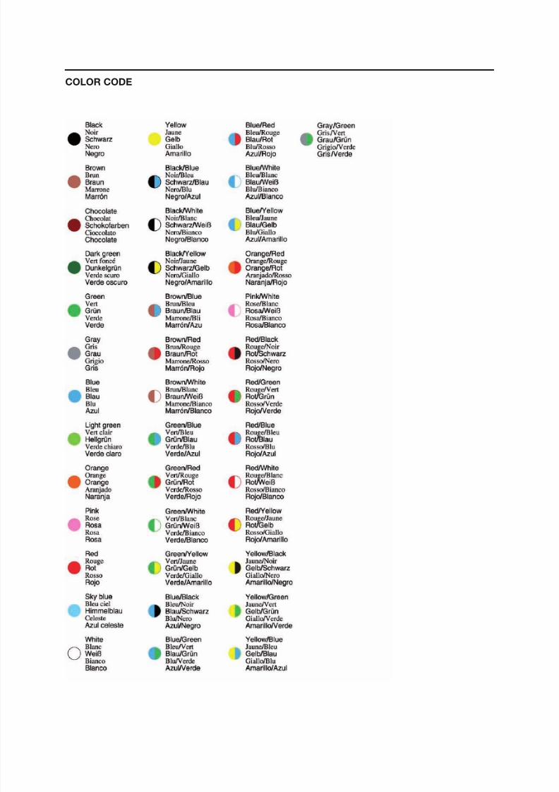
8/12/2019 Yamaha Tenere XT660Z Service Manual
http://slidepdf.com/reader/full/yamaha-tenere-xt660z-service-manual 396/398

8/12/2019 Yamaha Tenere XT660Z Service Manual
http://slidepdf.com/reader/full/yamaha-tenere-xt660z-service-manual 397/398

8/12/2019 Yamaha Tenere XT660Z Service Manual
http://slidepdf.com/reader/full/yamaha-tenere-xt660z-service-manual 398/398
XT660Z 2008 WIRING DIAGRAM


![LE PAROLE sostenére v. tr. [lat. sustĭnēre, comp. di sus-, variante di sub- «sotto», e tenere «tenere»] (coniug. come tenere). – Tenere sollevata una.](https://static.fdocumenti.com/doc/165x107/5542eb64497959361e8cd585/le-parole-sostenere-v-tr-lat-sustinere-comp-di-sus-variante-di-sub-sotto-e-tenere-tenere-coniug-come-tenere-tenere-sollevata-una.jpg)