Works J275 HA 2K20 532270 RevA - .NET Framework · 2021. 5. 21. · J275 HA 2K20 5 532270 - Rev.A...
22
J275 HA 2K20 Translation of the original instructions
Transcript of Works J275 HA 2K20 532270 RevA - .NET Framework · 2021. 5. 21. · J275 HA 2K20 5 532270 - Rev.A...

J275 HA 2K20
Translation of the original instructions
FAAC S.p.A. Soc. Unipersonale
Via Calari, 10 - 40069 Zola Predosa - BOLOGNA - ITALY
Tel. +39 051 61724 - Fax +39 051 09 57 820
www.faac.it - www.faacgroup.com
© Copyright FAAC S.p.A. dal 2020. Tutti i diritti riservati.
Nessuna parte di questo manuale può essere riprodotta, archiviata, distribuita a terzi né altrimenti copiata, in qualsiasi formato e con qualsiasi mezzo, sia esso elettronico, meccanico o tramite fotocopia, senza il preventivo consenso scritto di FAAC S.p.A.
Tutti i nomi e i marchi citati sono di proprietà dei rispettivi fabbricanti.
I clienti possono effettuare copie per esclusivo utilizzo proprio.
Questo manuale è stato pubblicato nel 2020.
© Copyright FAAC S.p.A. from 2020. All rights reserved.
No part of this manual may be reproduced, archived, distributed to third parties nor copied in any other way, in any format and with any means, be it electronic, mechanical or by photocopying, without prior written authorisation by FAAC S.p.A.
All names and trademarks mentioned are the property of their respective manu-facturers.
Customers may make copies exclusively for their own use.
This manual was published in 2020.
© Copyright FAAC S.p.A. depuis 2020. Tous droits réservés.
Aucune partie de ce manuel ne peut être reproduite, archivée ou distribuée à des tiers ni copiée, sous tout format et avec tout moyen, qu’il soit électronique, mécanique ou par photocopie, sans le consentement écrit préalable de FAAC S.p.A.
Tous les noms et les marques cités sont la propriété de leurs fabricants respectifs.
Les clients peuvent faire des copies pour leur usage exclusif.
Ce manuel a été publié en 2020.
© Copyright FAAC S.p.A. ab dem 2020. Alle Rechte vorbehalten.
Kein Teil dieses Handbuchs darf reproduziert, gespeichert, an Dritte weitergegeben oder sonst auf eine beliebige Art in einem beliebigen Format und mit beliebigen Mitteln kopiert werden, weder mit elektronischen, noch mechanischen oder durch Fotokopieren, ohne die Genehmigung von FAAC S.p.A.
Alle erwähnten Namen und Marken sind Eigentum der jeweiligen Hersteller.
Die Kunden dürfen nur für den Eigengebrauch Kopien anfertigen.
Dieses Handbuch wurde 2020 veröffentlicht.
© Copyright FAAC S.p.A. del 2020. Todos los derechos están reservados.
No puede reproducirse, archivarse, distribuirse a terceros ni copiarse de ningún modo, ninguna parte de este manual, con medios mecánicos o mediante fotocopia, sin el permiso previo por escrito de FAAC S.p.A.
Todos los nombre y las marcas citadas son de propiedad de los respectivos fabricantes.
Los clientes pueden realizar copias para su uso exclusivo.
Este manual se ha publicado en 2020.
© Copyright FAAC S.p.A. van 2020. Alle rechten voorbehouden.
Niets uit deze handleiding mag gereproduceerd, gearchiveerd, aan derden openbaar gemaakt of op andere wijze gekopieerd worden, in om het even welke vorm en met geen enkel middel, noch elektronisch, mechanisch of via fotokopiëren, zonder schrfitelijke toestemming vooraf van FAAC S.p.A.
Alle vermelde namen en merken zijn eigendom van de respectievelijke fabrikanten.
De klanten mogen kopieën maken die enkel voor eigen gebruik bestemd zijn.
Dez handleiding werd in 2020 gepubliceerd.
Tran
slatio
n of
the
orig
inal
inst
ruct
ions
ENGLIS
H

J275 HA 2K20 3 532270 - Rev.A
Tran
slatio
n of
the
orig
inal
inst
ruct
ions
ENGLIS
H
EU DECLARATION OF CONFORMITY
The Manufacturer
Company name: FAAC S.p.A. Soc. Unipersonale
Address: Via Calari, 10 - 40069 Zola Predosa - BOLOGNA - ITALY
hereby declares on his sole responsibility that the following products:
Description: Automatic retractable bollard
Model: J275 HA 2K20
comply with the following applicable EU legislations:
2014/30/EU/EU
2011/65/EU/EU
Furthermore, the following harmonised standards have been applied:
EN61000-6-2:2005
EN61000-6-3:2007 + A1:2011
Bologna, Italy, 11-01-2020 CEO
TABLES1 Symbols: notes and warnings on the instructions . . . . . . . . 42 Technical data . . . . . . . . . . . . . . . . . . . . . . . . . . . . . . . . . . . . . . . . . . . . . . . . . 83 Troubleshooting . . . . . . . . . . . . . . . . . . . . . . . . . . . . . . . . . . . . . . . . . . . . . 164 Routine maintenance. . . . . . . . . . . . . . . . . . . . . . . . . . . . . . . . . . . . . . . . 18
CONTENTSEU Declaration of conformity . . . . . . . . . . . . . . . . . . . . . . . . . . . . . . . . . . . 3EU Declaration of conformity . . . . . . . . . . . . . . . . . . . . . . . . . . . . . . . . . . . 3
1. INTRODUCTION TO THE INSTRUCTION MANUAL . . . . . . . . . . . 41.1 Meaning of the symbols used . . . . . . . . . . . . . . . . . . . . . . . . . . . . . . . . . . . 4
2. SAFETY RECOMMENDATIONS . . . . . . . . . . . . . . . . . . . . . . . . . . . . . . . . . . 52.1 Installer safety . . . . . . . . . . . . . . . . . . . . . . . . . . . . . . . . . . . . . . . . . . . . . . . . . . . . 52.2 Storing the product . . . . . . . . . . . . . . . . . . . . . . . . . . . . . . . . . . . . . . . . . . . . . . 52.3 Disposing of the product . . . . . . . . . . . . . . . . . . . . . . . . . . . . . . . . . . . . . . . . 5
3. J275 HA 2K20 . . . . . . . . . . . . . . . . . . . . . . . . . . . . . . . . . . . . . . . . . . . . . . . . . . . . . . . 63.1 Intended use . . . . . . . . . . . . . . . . . . . . . . . . . . . . . . . . . . . . . . . . . . . . . . . . . . . . . . 63.2 Limitations of use . . . . . . . . . . . . . . . . . . . . . . . . . . . . . . . . . . . . . . . . . . . . . . . . . 63.3 Unauthorised use . . . . . . . . . . . . . . . . . . . . . . . . . . . . . . . . . . . . . . . . . . . . . . . . . 63.4 Emergency use . . . . . . . . . . . . . . . . . . . . . . . . . . . . . . . . . . . . . . . . . . . . . . . . . . . . 63.5 Product identification . . . . . . . . . . . . . . . . . . . . . . . . . . . . . . . . . . . . . . . . . . . . 63.6 Technical characteristics . . . . . . . . . . . . . . . . . . . . . . . . . . . . . . . . . . . . . . . . . 73.7 Component identification . . . . . . . . . . . . . . . . . . . . . . . . . . . . . . . . . . . . . . . 7
Installation accessories (supplied separately) . . . . . . . . . . . . . . . . 7Optional Accessories . . . . . . . . . . . . . . . . . . . . . . . . . . . . . . . . . . . . . . . . . . . . 8
3.8 Dimensional drawing . . . . . . . . . . . . . . . . . . . . . . . . . . . . . . . . . . . . . . . . . . . . 8
4. INSTALLATION REQUIREMENTS . . . . . . . . . . . . . . . . . . . . . . . . . . . . . . . . 94.1 Mechanical requirements . . . . . . . . . . . . . . . . . . . . . . . . . . . . . . . . . . . . . . . . 94.2 Electrical system . . . . . . . . . . . . . . . . . . . . . . . . . . . . . . . . . . . . . . . . . . . . . . . . . . 9
5. INSTALLATION . . . . . . . . . . . . . . . . . . . . . . . . . . . . . . . . . . . . . . . . . . . . . . . . . . . 105.1 Installing the bollard . . . . . . . . . . . . . . . . . . . . . . . . . . . . . . . . . . . . . . . . . . . . 105.2 Manual operation. . . . . . . . . . . . . . . . . . . . . . . . . . . . . . . . . . . . . . . . . . . . . . . . 11
Release procedure . . . . . . . . . . . . . . . . . . . . . . . . . . . . . . . . . . . . . . . . . . . . . . 11Restoring automatic operation . . . . . . . . . . . . . . . . . . . . . . . . . . . . . . . 12
5.3 Connections . . . . . . . . . . . . . . . . . . . . . . . . . . . . . . . . . . . . . . . . . . . . . . . . . . . . . . 135.4 Board programming. . . . . . . . . . . . . . . . . . . . . . . . . . . . . . . . . . . . . . . . . . . . . 145.5 Connecting multiple bollards . . . . . . . . . . . . . . . . . . . . . . . . . . . . . . . . . . 145.6 Troubleshooting . . . . . . . . . . . . . . . . . . . . . . . . . . . . . . . . . . . . . . . . . . . . . . . . . 16
6. MAINTENANCE . . . . . . . . . . . . . . . . . . . . . . . . . . . . . . . . . . . . . . . . . . . . . . . . . . . 176.1 Removing the hydraulic unit . . . . . . . . . . . . . . . . . . . . . . . . . . . . . . . . . . . 176.2 Topping up the oil level . . . . . . . . . . . . . . . . . . . . . . . . . . . . . . . . . . . . . . . . . 186.3 Bleeding the system . . . . . . . . . . . . . . . . . . . . . . . . . . . . . . . . . . . . . . . . . . . . . 186.4 Routine maintenance . . . . . . . . . . . . . . . . . . . . . . . . . . . . . . . . . . . . . . . . . . . 18
7. INSTALLING OPTIONAL EQUIPMENT . . . . . . . . . . . . . . . . . . . . . . . . 197.1 Installing the pressure switch . . . . . . . . . . . . . . . . . . . . . . . . . . . . . . . . . . 19
Multiple connections . . . . . . . . . . . . . . . . . . . . . . . . . . . . . . . . . . . . . . . . . . . 197.2 Installing the solenoid valve . . . . . . . . . . . . . . . . . . . . . . . . . . . . . . . . . . . . 20
Connecting the control coil . . . . . . . . . . . . . . . . . . . . . . . . . . . . . . . . . . . . 20Multiple connections . . . . . . . . . . . . . . . . . . . . . . . . . . . . . . . . . . . . . . . . . . . 21
7.3 Cover . . . . . . . . . . . . . . . . . . . . . . . . . . . . . . . . . . . . . . . . . . . . . . . . . . . . . . . . . . . . . . 21
A. Marcellan
EU DECLARATION OF CONFORMITY
The Manufacturer
Company name: FAAC S.p.A. Soc. Unipersonale
Address: Via Calari, 10 - 40069 Zola Predosa - BOLOGNA - ITALY
hereby declares on his sole responsibility that the following products:
Description: Automatic retractable bollard
Model: J275 HA 2K20
comply with the following applicable EU legislations:
2014/30/EU
2011/65/EU
Furthermore, the following harmonised standards have been applied:
EN61000-6-2:2005
EN61000-6-3:2007 + A1:2011
Bologna, Italy, 26-11-2020 CEO
A. Marcellan
DECLARATION OF INCORPORATION FOR PARTLY COMPLETED MACHINERY
(2006/42/EC ALL.II P.1, LETT. B)
Manufacturer and person authorised to prepare the relevant technical documentation
Company name: FAAC S.p.A. Soc. Unipersonale
Address: Via Calari, 10 - 40069 Zola Predosa - BOLOGNA - ITALY
hereby declares that for the partly completed machinery:
Description: Automatic retractable bollard
Model: J275 HA 2K20
The essential requirements of the Machinery Directive 2006/42/EC (including all applicable amendments) that have been applied and fulfilled are as follows:
1.1.2, 1.1.3, 1.1.5, 1.3.1, 1.3.2, 1.3.4, 1.5.1, 1.5.3, 1.5.5,1.5.6, 1.5.7, 1.5.15, 1.6.1, 1.6.2, 1.6.3, 1.6.4, 1.7.1, 1.7.2, 1.7.3, 1.7.4.1, 1.7.4.2, 1.7.4.3
and that the relevant technical documentation has been compiled in compliance with part B of Annex VII.
Furthermore, the following harmonised standards have been applied:
EN12100:2010
EN60335-1:2012+A11:2014+A13:2017
And also undertakes to transmit, in response to a reasoned request by the national au-thorities, relevant information on the partly completed machinery by mail or e-mail.
Finally, the manufacturer declares that the above-mentioned partly completed machinery must not be put into service until the final machine in which it is to be incorporated has been declared compliant with the requirements of the above-mentioned Machinery Directive 2006/42/EC.
Bologna, Italy
26-11-2020
CEO
A. Marcellan

J275 HA 2K20 4 532270 - Rev.A
Tran
slatio
n of
the
orig
inal
inst
ruct
ions
ENGLIS
H
This manual provides the correct procedures and requirements for installing J275 HA 2K20 and maintaining it in a safe condition.When drafting the manual, the results of the risk assessment con-ducted by FAAC S.p.A. on the entire product life cycle have been taken into account in order to implement effective risk reduction measures.The following stages of the life cycle of the product have been con-sidered:- Delivery/handling- Assembly and installation- Set-up and commissioning- Operation- Maintenance/troubleshooting- Disposal at the end of the product’s life cycle
Risks arising from installation and using the product have been taken into consideration; these include:- Risks for the installation/maintenance technician (technical
personnel)- Risks for the user of the automation system- Risks to product integrity (damage)
In Europe, the automation of a bollard falls under the Machinery Directive 2006/42/EC and the corresponding harmonised stan-dards. Anyone automating bollard (new or existing) is classified as the Manufacturer of the Machine. They are therefore required by law, among other things, to carry out a risk analysis of the machine (bollard in its entirety) and take protective measures to fulfil the essential safety requirements specified in Annex I of the Machinery Directive.FAAC S.p.A. recommends that you always comply with the EN 12453standard and in particular that you adopt the safety criteria and de-vices indicated, without exception, including the dead-man function. This manual also contains general information and guidelines, which are purely illustrative and not exhaustive, in order to facilitate the ac-tivities carried out by the Manufacturer of the Machine in all respects with regard to carrying out the risk analysis and drafting the instruc-tions for use and maintenance of the machine. It should be clearly understood that FAAC S.p.A. accepts no liability for the reliability and/ or completeness of the above instructions. As such, the manufacturer of the machine must carry out all the activities required by the Machi-nery Directive and the corresponding harmonised standards on the basis of the actual condition of the locations and structures where the product J275 HA 2K20 will be installed, prior to commissioning the machine. These activities include the analysis of all the risks associated with the machine and subsequent implementation of all safety measures intended to fulfil the essential safety requirements.This manual contains references to European standards. The auto-mation of a bollard must fully comply with any laws, standards and regulations applicable in the country where installation will take place.
Unless otherwise specified, the measurements provided in the instruc-tions are in mm.
1. INTRODUCTION TO THE INSTRUCTION MANUAL
1.1 MEANING OF THE SYMBOLS USED1 Symbols: notes and warnings on the instructions
FWARNING ELECTRIC SHOCK HAZARD - The operation or stage described must be performed following the supplied instructions and applicable safety regulations.
!WARNING, PERSONAL INJURY HAZARD OR RISK OF DAMAGE TO COMPO-NENTS - The procedure or step described must be carried out following the instructions provided and according to the applicable safety regulations.
WARNING - Details and specifications which must be respected in order to ensure that the system operates correctly.
RECYCLING and DISPOSAL - Components and structural materials, batteries and electronic components must not be disposed of together with household waste. They must be taken to authorised disposal and recycling centres.
For manual lifting, there should be 1 person for every 20 kg to be lifted.
PAGE E.g.: 6 see Page 6.
FIGURE E.g.: 1 -3 see Figure 1 - detail 3.
TABLE E.g.: 1 see Table 1.
§ CHAPTER/SECTION E.g.: §1.1 see section 1.1.
APPENDIX E.g.: 1 see Appendix 1.
J275 HA 2K20 5 532270 - Rev.A
Tran
slatio
n of
the
orig
inal
inst
ruct
ions
ENGLIS
H
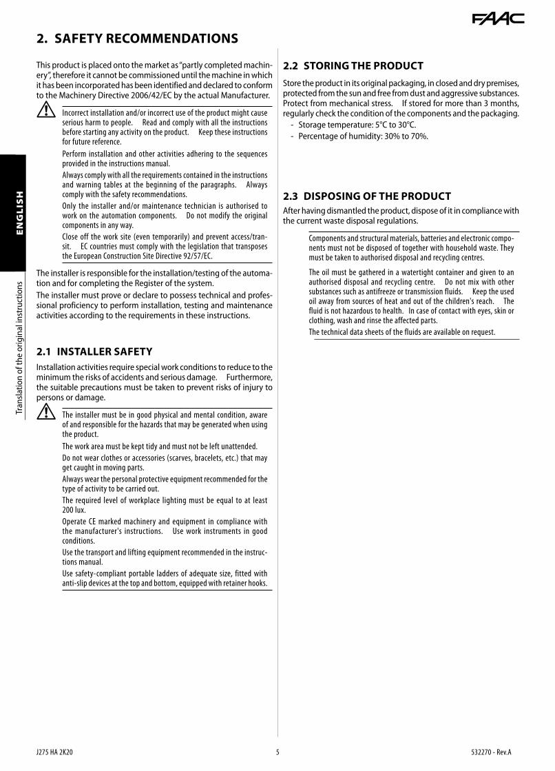
2. SAFETY RECOMMENDATIONS
This product is placed onto the market as “partly completed machin-ery”, therefore it cannot be commissioned until the machine in which it has been incorporated has been identified and declared to conform to the Machinery Directive 2006/42/EC by the actual Manufacturer.
! Incorrect installation and/or incorrect use of the product might cause serious harm to people. Read and comply with all the instructions before starting any activity on the product. Keep these instructions for future reference.
Perform installation and other activities adhering to the sequences provided in the instructions manual.
Always comply with all the requirements contained in the instructions and warning tables at the beginning of the paragraphs. Always comply with the safety recommendations.
Only the installer and/or maintenance technician is authorised to work on the automation components. Do not modify the original components in any way.
Close off the work site (even temporarily) and prevent access/tran-sit. EC countries must comply with the legislation that transposes the European Construction Site Directive 92/57/EC.
The installer is responsible for the installation/testing of the automa-tion and for completing the Register of the system.The installer must prove or declare to possess technical and profes-sional proficiency to perform installation, testing and maintenance activities according to the requirements in these instructions.
Installation activities require special work conditions to reduce to the minimum the risks of accidents and serious damage. Furthermore, the suitable precautions must be taken to prevent risks of injury to persons or damage.
! The installer must be in good physical and mental condition, aware of and responsible for the hazards that may be generated when using the product.
The work area must be kept tidy and must not be left unattended.
Do not wear clothes or accessories (scarves, bracelets, etc.) that may get caught in moving parts.
Always wear the personal protective equipment recommended for the type of activity to be carried out.
The required level of workplace lighting must be equal to at least 200 lux.
Operate CE marked machinery and equipment in compliance with the manufacturer's instructions. Use work instruments in good conditions.
Use the transport and lifting equipment recommended in the instruc-tions manual.
Use safety-compliant portable ladders of adequate size, fitted with anti-slip devices at the top and bottom, equipped with retainer hooks.
2.1 INSTALLER SAFETY
Store the product in its original packaging, in closed and dry premises, protected from the sun and free from dust and aggressive substances. Protect from mechanical stress. If stored for more than 3 months, regularly check the condition of the components and the packaging.- Storage temperature: 5°C to 30°C.- Percentage of humidity: 30% to 70%.
After having dismantled the product, dispose of it in compliance with the current waste disposal regulations.
Components and structural materials, batteries and electronic compo-nents must not be disposed of together with household waste. They must be taken to authorised disposal and recycling centres.
The oil must be gathered in a watertight container and given to an authorised disposal and recycling centre. Do not mix with other substances such as antifreeze or transmission fluids. Keep the used oil away from sources of heat and out of the children's reach. The fluid is not hazardous to health. In case of contact with eyes, skin or clothing, wash and rinse the affected parts.
The technical data sheets of the fluids are available on request.
2.2 STORING THE PRODUCT
2.3 DISPOSING OF THE PRODUCT
1
J275 HA 2K20 6 532270 - Rev.A
J275 HA 2K20
MM/YY PROG
MMYYPROG
••••••
••••••••••••••••
••••••••
••••••
•••• ••••••••
Tran
slatio
n of
the
orig
inal
inst
ruct
ions
ENGLIS
H
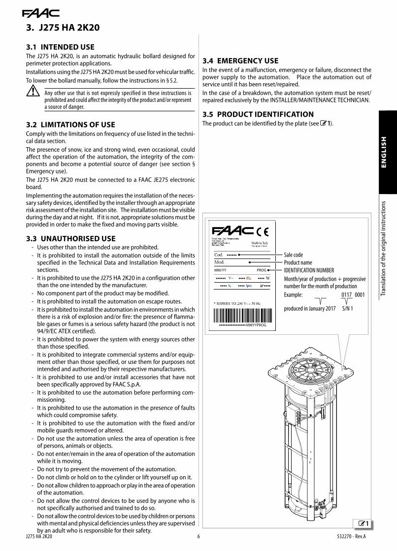
3. J275 HA 2K20
3.1 INTENDED USEThe J275 HA 2K20, is an automatic hydraulic bollard designed for perimeter protection applications.Installations using the J275 HA 2K20 must be used for vehicular traffic.To lower the bollard manually, follow the instructions in § 5.2.
! Any other use that is not expressly specified in these instructions is prohibited and could affect the integrity of the product and/or represent a source of danger.
3.2 LIMITATIONS OF USEComply with the limitations on frequency of use listed in the techni-cal data section.The presence of snow, ice and strong wind, even occasional, could affect the operation of the automation, the integrity of the com-ponents and become a potential source of danger (see section §Emergency use). The J275 HA 2K20 must be connected to a FAAC JE275 electronic board.Implementing the automation requires the installation of the neces-sary safety devices, identified by the installer through an appropriate risk assessment of the installation site. The installation must be visible during the day and at night. If it is not, appropriate solutions must be provided in order to make the fixed and moving parts visible .
3.3 UNAUTHORISED USE- Uses other than the intended use are prohibited.- It is prohibited to install the automation outside of the limits
specified in the Technical Data and Installation Requirements sections.
- It is prohibited to use the J275 HA 2K20 in a configuration other than the one intended by the manufacturer.
- No component part of the product may be modified.- It is prohibited to install the automation on escape routes.- It is prohibited to install the automation in environments in which
there is a risk of explosion and/or fire: the presence of flamma-ble gases or fumes is a serious safety hazard (the product is not 94/9/EC ATEX certified).
- It is prohibited to power the system with energy sources other than those specified.
- It is prohibited to integrate commercial systems and/or equip-ment other than those specified, or use them for purposes not intended and authorised by their respective manufacturers.
- It is prohibited to use and/or install accessories that have not been specifically approved by FAAC S.p.A.
- It is prohibited to use the automation before performing com-missioning.
- It is prohibited to use the automation in the presence of faults which could compromise safety.
- It is prohibited to use the automation with the fixed and/or mobile guards removed or altered.
- Do not use the automation unless the area of operation is free of persons, animals or objects.
- Do not enter/remain in the area of operation of the automation while it is moving.
- Do not try to prevent the movement of the automation.- Do not climb or hold on to the cylinder or lift yourself up on it. - Do not allow children to approach or play in the area of operation
of the automation.- Do not allow the control devices to be used by anyone who is
not specifically authorised and trained to do so.- Do not allow the control devices to be used by children or persons
with mental and physical deficiencies unless they are supervised by an adult who is responsible for their safety.
3.4 EMERGENCY USEIn the event of a malfunction, emergency or failure, disconnect the power supply to the automation. Place the automation out of service until it has been reset/repaired.In the case of a breakdown, the automation system must be reset/repaired exclusively by the INSTALLER/MAINTENANCE TECHNICIAN.
3.5 PRODUCT IDENTIFICATIONThe product can be identified by the plate (see 1 ).
Sale code
Product name
IDENTIFICATION NUMBER
Month/year of production + progressive number for the month of production
Example: 0117 0001
produced in January 2017 S/N 1

2
J275 HA 2K20 7 532270 - Rev.A
2
5
9
72
1
8
4
5
10
11
1
15
3
14
13
16
6
12
3
4
Tran
slatio
n of
the
orig
inal
inst
ruct
ions
ENGLIS
H
1 Flashing LED light
2 Head
3 Oil filler plug
4 Hydraulic unit lifting handle
5 Hydraulic unit
6 Top cover
7 High position magnetic contacts (1 NC / 1 NO)
8 Sliding guides
9 Frame
10 Low position mechanical stops (4)
11 Low position magnetic contact (N.C.)
12 High position mechanical stops (4)
13 External junction box
14 Cylinder
15 Internal junction box
16 Head removal key
INSTALLATION ACCESSORIES (SUPPLIED SEPARATELY)
1 Subframe
2 Side module with cable routing hole (x1)
3 Cable gland
4 Side module (x7)
5 Base with water drainage holes
Pit
3.7 COMPONENT IDENTIFICATION
3.6 TECHNICAL CHARACTERISTICSThe cylinder is moved by an internal hydraulic unit. A release device, protected by a security lock, to lower the cylinder can be accessed from the top. The thrust capacitor is pre-wired and housed in the internal junction box.Certifications The J275 HA 2K20 bollard is certified according to the following standards and relative performance levels:- PAS 68:2013 V/7500 (N2)/48/90:1.7/0.0- IWA 14–1:2013 V/7200 [N2A]/48/90:1.9
Optional equipment
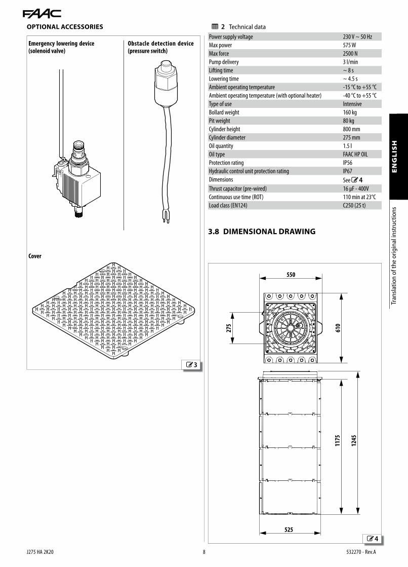
- Emergency lowering device: a solenoid valve connected to the mains power supply allows the cylinder to be lowered automatically in the event of a power failure.
- Obstacle detection device: allows the closing movement to be reversed if an obstacle (e.g. a vehicle) is detected.
3
4
J275 HA 2K20 8 532270 - Rev.A
1245
1175
525
275
610
550
Tran
slatio
n of
the
orig
inal
inst
ruct
ions
ENGLIS
H
OPTIONAL ACCESSORIES
Emergency lowering device (solenoid valve)
Obstacle detection device (pressure switch)
Cover
2 Technical dataPower supply voltage 230 V ~ 50 Hz
Max power 575 W
Max force 2500 N
Pump delivery 3 l/min
Lifting time ~ 8 s
Lowering time ~ 4.5 s
Ambient operating temperature -15 °C to +55 °C
Ambient operating temperature (with optional heater) -40 °C to +55 °C
Type of use Intensive
Bollard weight 160 kg
Pit weight 80 kg
Cylinder height 800 mm
Cylinder diameter 275 mm
Oil quantity 1.5 l
Oil type FAAC HP OIL
Protection rating IP56
Hydraulic control unit protection rating IP67
Dimensions See 4
Thrust capacitor (pre-wired) 16 μF - 400V
Continuous use time (ROT) 110 min at 23°C
Load class (EN124) C250 (25 t)
3.8 DIMENSIONAL DRAWING

J275 HA 2K20 9 532270 - Rev.A
Tran
slatio
n of
the
orig
inal
inst
ruct
ions
ENGLIS
H
4. INSTALLATION REQUIREMENTS
4.1 MECHANICAL REQUIREMENTSThe essential mechanical requirements for each bollard are as follows:- a pit as indicated in the foundation diagram- a flexible conduit suitable for electrical connections- a cage and foundation plinth- flat ground
The foundation diagram is supplied with the pit and shows a double unit installation. For information about the foundation diagram for a multiple bollard configuration, please contact FAAC technical support.
4.2 ELECTRICAL SYSTEM
F Always shut off the power supply before performing any work. If the disconnect switch is not in view, apply a warning sign stating “WARN-ING - Maintenance in Progress”.
! The electrical system must comply with applicable legislation in the country of installation. In Europe, the electrical system must comply with standard EN 60335.
Use components and materials with a CE marking that are compli-ant with the Low Voltage Directive 2014/35/EU and EMC Directive 2014/30/EU.
The electrical cables of the system must be of a size and insulation class that is compliant with current legislation and laid in appropriate rigid or flexible conduits, either above or below ground.
The automation power supply for each bollard must be fitted with:
- a multi-pole thermal magnetic circuit breaker, with a suitable tripping threshold, a contact opening distance of at least 3 mm and a breaking capacity that complies with current regulations
- a 0.03 A differential switch
The thermal magnetic and differential circuit breakers must be located in areas that are only accessible to authorized personnel.
The metal parts of the structure must be earthed.
Check that the protective earthing system complies with applicable regulations in the country of installation.
Provide the following for each bollard:
- an FG7OR-0.6/1kV-16G1.5 cable, maximum length 50 m. This code refers to European standards and describes a cable with ethylene propylene rubber insulated conductors, PVC outer sheath, nominal voltage 0.6 kV, maximum voltage 1 kV, 16 conductors, one of which is an earth, section of conductor 1.5 mm2
Provide an electronic board for every three bollards.
Provide suitable enclosures for the installation of electronic boards and electrical components. The containers must have a minimum IP44 protection and must be fitted with a lock or other device to prevent ac-cess by unauthorized persons. The cable outlets must face downwards.
In the case of a Master-Slave configuration, a cable conduit has to be installed for the cables that connect the two electronic boards.
Check buried cable plans to ensure that there are no other electrical cables in proximity to the planned digging/drilling locations to prevent the risk of electrocution.
Check that there are no pipes in the vicinity as well.
The conduit fittings and the cable glands must prevent the entry of moisture, insects and small animals.
Protect extension cable connections using junction boxes with an IP67 protection rating or higher.
The bollard must always be visible to prevent it from being hit ac-cidentally. An adequate lighting system is required.
It is recommended to position the control devices within the field of view of the automation. This is mandatory in the case of hold-to-run controls.
The maintained action controls in the hold-to-run mode of operation, must comply with standard EN 60947-5-1.
The control devices must be located in areas that are only accessible to authorized personnel.
If an emergency stop button has been installed, it must be EN13850 compliant.
Comply with the following heights from the ground:
- control accessories = minimum 150 cm
- emergency button = maximum 120 cm

5
6
7
8
J275 HA 2K20 10 532270 - Rev.A
1
2
3
5
Tran
slatio
n of
the
orig
inal
inst
ruct
ions
ENGLIS
H
5. INSTALLATION
5.1 INSTALLING THE BOLLARD
! Use a 1.5mm2 16 core (15 + earth) cable for the electrical connec-tions. Use a cable that complies with local regulations for use with 230 V~.
The maximum cable length is 50 m.
1. Place the cable inside the flexible sheath and make it protrude from the pit by 1.6m.
2. 5 Fasten the cable to the frame using the cable gland provided 1 .3. Insert the cable into the external junction box 3 through the cable
gland provided 2.
4. Connect the conductors to the external junction box and the control board following the instructions in section § 5.3.
5. Check that the bollard operates correctly, according to the logics set on the board, as well as all the accessories that are connected.
6. Remove the top cover 6 .7. Screw the two M10 eyebolts, provided, onto the top of the frame 7 .8. Lift the bollard and insert it completely into the pit. 8 . Position the
bollard so that the junction box is on the same side as the cable inlet.
! Use belts or chains and a lifting device that are suitable for the weight of the bollard.
Take care not to damage the electrical cable by pinching it between the frame and the pit.

9
10
11
12
J275 HA 2K20 11 532270 - Rev.A
5
8T30
10
45 Nm
1
3
2
2
1
24
90 Nm
Tran
slatio
n of
the
orig
inal
inst
ruct
ions
ENGLIS
H
9. Remove the eyebolts and fasten the bollard to the pit using the ten M12x30 screws and the eight M16x30 screws. Apply the fastening torques given in 9.
10. Fasten the cover to the frame using the eight M6x20 screws.
To reposition or lift the cover, prise one of the two slots upwards using a screwdriver.
5.2 MANUAL OPERATION
! Before carrying out the release procedure, disconnect the power supply to the automation system.
RELEASE PROCEDURE1. 11Remove the plugs 1 and unscrew the screws 2.2. Unscrew the plug 3.
3. 12 Insert the key 1 and turn it anticlockwise until it stops 2.

13
15
14
16
17
J275 HA 2K20 12 532270 - Rev.A
8T30
1
2
1
3
2
Tran
slatio
n of
the
orig
inal
inst
ruct
ions
ENGLIS
H
5. 17Put back the screws 2 and the plug 3. 6. Replace the plugs 1.
4. Lift the head in order to access the release device.
5. Actuate the release device by turning the knob anticlockwise.
RESTORING AUTOMATIC OPERATION1. 14Actuate the release device by turning the knob anticlock-
wise as far as it will go, but without forcing it.2. 15Position the head.
3. 16Turn the key clockwise by 90° 1.4. Remove the key 2.

18
J275 HA 2K20 13 532270 - Rev.A
1
2
3
4
5
6
7
8
9
10
11
PE
LN
1918
OU
T 4
GN
D
16 17151412 13118 96 74 52 3 101
OPEN
A
STOP
LOO
P 1
LOO
P 2
LOO
P 2
LOO
P 1
CLOSE
FSW
EMERG
ENC
Y
OU
T 1
OU
T 2
OU
T 3
GN
D
GN
D
+24 V
+24 V
OU
T 3
252321 26242220
MO
T1
COM
MO
T2
COM
COM
LAM
P
FAN
J1N LPE
J5J3
12
J2 J9
M~
S
13
1234578610 9
12 13 11
+24V
Tran
slatio
n of
the
orig
inal
inst
ruct
ions
ENGLIS
H
5.3 CONNECTIONS
Lights
UPPER limit switch
UPPER limit switch
LOWER limit switch
LOWER limit switch
Communal limit switch
Pressure Switch Common*
Solenoid valve*
Solenoid valve*
Motor - Opening
Motor - Common
Motor - Closing
Pressure Switch Signal*
Buzzer
* optional accessories

19
20
J275 HA 2K20 14 532270 - Rev.A
1918 OUT 4
GND
1617
1514
1213
1189
67
45
23
101
OPEN A
STOP
LOOP 1
LOOP 2
LOOP 2
LOOP 1
CLOSE
FSW
EMERGENCY
OUT 1
OUT 2
OUT 3
GND
GND
+24 V
+24 V
OUT 3
2523
2126
2422
20
MOT1
COM
MOT2
COM
COM
LAMP
FAN
J1
J2
M1~
M2~
M3~
1
2
3
J5
J3
1 2 3
1 2 3
Tran
slatio
n of
the
orig
inal
inst
ruct
ions
ENGLIS
H
5.5 CONNECTING MULTIPLE BOLLARDSUp to 3 bollards can be connected simultaneously to a single JE275 board. To connect them, follow the diagrams below.
UPPER limit switch
LOWER limit switch
5.4 BOARD PROGRAMMINGAfter connecting and switching on the power to the control board as per the previous chapter, select the work pre-setting for the bollard J275 HA 2K20 by performing the following operation:1. Access level 1 programming by holding down the F button on the
board (19 ). The letters dF will appear on the display.2. Release the F button and with the ++ button, select the value 053. Press the F button and hold it down whilst simultaneously pressing
the - button to exit programming screen and save the changes made.
4. Press the F button and hold it down, as well as pressing + for around 10 seconds, until the display shows 01
5. Release the buttons, then press the F button scroll until you reach the b6 parameter
6. Set the value b6 = Y
! Setting b6 = Y causes the bollard to raise immediately when the emergency input is activated.
7. Press the F button and hold it down whilst simultaneously pressing the - button to exit programming screen and save the changes made.
For further information on programming the board, please refer to the relevant instructions.

21
J275 HA 2K20 15 532270 - Rev.A
1918 OUT 4
GND
1617
1514
1213
1189
67
45
23
101
OPEN A
STOP
LOOP 1
LOOP 2
LOOP 2
LOOP 1
CLOSE
FSW
EMERGENCY
OUT 1
OUT 2
OUT 3
GND
GND
+24 V
+24 V
OUT 3
2523
2126
2422
20
MOT1
COM
MOT2
COM
COM
LAMP
FAN
J1
J2
M1~
M2~
M3~
1
2
3
1918 OUT 4
GND
1617
1514
1213
1189
67
45
23
101
OPEN A
STOP
LOOP 1
LOOP 2
LOOP 2
LOOP 1
CLOSE
FSW
EMERGENCY
OUT 1
OUT 2
OUT 3
GND
GND
+24 V
+24 V
OUT 3
2523
2126
2422
20
MOT1
COM
MOT2
COM
COM
LAMP
FAN
J1
J2
M4~
M5~
M6~
1
2
3
4
5
6
J5
J3
1 2 3
1 2 3
J5
J3
4 5 6
4 5 6
1. dF = 05
2. o 1 = 1 1 P1 = no o 2 = 12 P2 = no
3. b6 = Y
F
F+
-
F+
+
F+
-
F+
+ F+
-
10 s
1. dF = 05 LO = C
2. 03 = Y b6 = Y
3. LO = Cu
4. o 3 = 1 5 P3 = no
F
F
F+
-
F+
+
F+
-
F+
-
10 s
F+
+
F+
-
F+
- F+
-
Tran
slatio
n of
the
orig
inal
inst
ruct
ions
ENGLIS
H
If the total number of bollards in the system is greater than 3, connect 2 or more boards in a master-slave configuration as indicated below. A single master board can control multiple slave boards at the same time.
! It is recommended to balance the load on the boards (e.g. for 4 bollards, connect 2 bollards to the master board and 2 bollards to the slave board.
Master JE275 board
Slave JE275 board

J275 HA 2K20 16 532270 - Rev.A
Tran
slatio
n of
the
orig
inal
inst
ruct
ions
ENGLIS
H
5.6 TROUBLESHOOTINGBelow are a series of tips to help identify and solve a number of particular issues.
3 TroubleshootingCONDITION SUGGESTION
The bollard raises by a few centime-tres and then lowers immediately
Make sure that you have selected default No. 5 on the JE275 board (§ 5.4)
Make sure that the DL3 (FSW) LED on the JE275 board remains on for the entire move-ment.
Make sure that the pressure switch (if present) has been wired correctly.
Replace the pressure switch (if present)
The bollard reaches the high position and reverses immediately.
Make sure that the limit switches are wired correctly. 18
Make sure that the upper limit switch is in the correct position 2 -7
The bollard does not raise.
Make sure that you have selected default No. 5 on the JE275 board (§ 5.4)
Make sure that the bollard is set for automatic operation (§ 5.2)
Check the wiring of the motor
The bollard will not lower, and remains in the high closed position.
Check that there is nothing between the cyl-inder and the slide bushing that is preventing movement
Check the wiring of the motor
The flashing LED light is not working
Make sure that you have selected default No. 5 on the JE275 board (§ 5.4)
Make sure that the power supply connector located under the head is plugged in correctly.
Check the accessories fuse on the JE275 board.
25
22
23
24
J275 HA 2K20 17 532270 - Rev.A
6
Tran
slatio
n of
the
orig
inal
inst
ruct
ions
ENGLIS
H
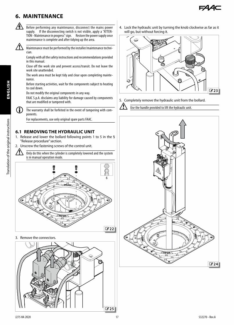
6. MAINTENANCE
F Before performing any maintenance, disconnect the mains power supply. If the disconnecting switch is not visible, apply a "ATTEN-TION - Maintenance in progress" sign. Restore the power supply once maintenance is complete and after tidying up the area.
! Maintenance must be performed by the installer/maintenance techni-cian.
Comply with all the safety instructions and recommendations provided in this manual.
Close off the work site and prevent access/transit. Do not leave the work site unattended.
The work area must be kept tidy and clear upon completing mainte-nance.
Before starting activities, wait for the components subject to heating to cool down.
Do not modify the original components in any way.
FAAC S.p.A. disclaims any liability for damage caused by components that are modified or tampered with.
The warranty shall be forfeited in the event of tampering with com-ponents.
For replacements, use only original spare parts FAAC.
6.1 REMOVING THE HYDRAULIC UNIT1. Release and lower the bollard following points 1 to 5 in the §
"Release procedure” section.2. Unscrew the fastening screws of the control unit.
! Only do this when the cylinder is completely lowered and the system is in manual operation mode.
3. Remove the connectors.
4. Lock the hydraulic unit by turning the knob clockwise as far as it will go, but without forcing it.
5. Completely remove the hydraulic unit from the bollard.
! Use the handle provided to lift the hydraulic unit.

26
J275 HA 2K20 18 532270 - Rev.A
Tran
slatio
n of
the
orig
inal
inst
ruct
ions
ENGLIS
H
6.4 ROUTINE MAINTENANCE The Scheduled Maintenance table lists the operations that must be performed on a regular basis in order to keep the automation sys-tem working reliably and safely; these are given purely as a guideline and should not be considered exhaustive. The installer/machine manufacturer is responsible for drawing up the maintenance plan for the automation system, supplementing this list or modifying the maintenance intervals according to the machine characteristics.
4 Routine maintenance
OperationFr e q u e n c y (months)
Clean the pit. 6
Check the drainage. 6
Clean the sliding guides 6
Make sure that there are no oil leaks 12
Top up the oil level, if necessary. Only use FAAC oil 12
Check the condition of the actuator cables, the cable glands and junc-tion boxes.
12
Check that screws and bolts are correctly tightened. 12
Check the mechanical stops: fastening and solidity. 12
Make sure that the cylinder is clean and if necessary touch up the paintwork.
Check that the automation system operates correctly, following the set logic, when using the various control devices.
12
6.2 TOPPING UP THE OIL LEVEL1. Release and lower the bollard following points 1 to 5 in the §
"Release procedure” section.2. Unscrew the plug of the hydraulic unit 26 .
The oil level should be checked when the bollard is in the lowered position.
An overflow pipe below the plug prevents the control unit from be-coming too full. There should be oil in the pipe when the cylinder is in the down position. If necessary, top up the oil to the rim of the pipe.
3. Close the automation.4. Replace the plug of the hydraulic unit when the bollard is in the
raised position.5. Install the head following points 2 to 6 in the § “Restoring auto-
matic operation” section.
6.3 BLEEDING THE SYSTEM1. Remove the head of the bollard following points 1 to 4 in the §
"Release procedure” section.2. Unscrew the plug of the hydraulic unit.3. Open and close the automation several times with the plug
removed.4. Replace the plug of the hydraulic unit when the bollard is in the
raised position.5. Install the head following points 2 to 6 in the § “Restoring auto-
matic operation” section.

27
28
29
30
J275 HA 2K20 19 532270 - Rev.A
1
2
5
24
35 Nm
2
1
3
3
12345
615
141213
11
OUT 1
OUT 2
GND
+24 V
+24 V
OUT 3
89
710
STOP
FSW
EMERGENCY
GND019
18 OUT 4
GND
1617
1514
1213
116 CLOSE
OUT 1
OUT 2
OUT 3
GND
+24 V
+24 V
OUT 3
89
710
STOP
FSW
EMERGENCY
GND0
Tran
slatio
n of
the
orig
inal
inst
ruct
ions
ENGLIS
H
7. INSTALLING OPTIONAL EQUIPMENT
7.1 INSTALLING THE PRESSURE SWITCH1. 27 Remove the hydraulic unit following points 1 to 5 in the §
"Removing the hydraulic unit” section.2. Place the hydraulic unit in a horizontal position.3. Remove the plug from the flange 1 and the plug from the cable
gland 2.
4. 28 Screw the pressure switch 1 onto the flange, together with the seal provided. Insert the cable in to the cable gland 2 and connect it to connector 3 inside the junction box according to the diagram shown in the figure.
Violet
BlueBlue
Brown
Make sure that terminals 9 and 10 of the external junction box of the bollard are connected to the JE275 control board as per 18 . Otherwise, connect them now.
Carry out a bleed cycle after having reinstalled the hydraulic unit.
MULTIPLE CONNECTIONSIf multiple bollards (max 3) are installed, which are controlled by a single JE275 board, connect the pressure switches in series as indi-cated in the following diagram.
If multiple bollards (more than 3) are installed, which are controlled by JE275 boards in a master / slave configuration, connect all the pres-sure switches in series on the inputs of the master board as indicated in the following diagram.
Master JE275 board

31
32
33
34
35
J275 HA 2K20 20 532270 - Rev.A
24
45 Nm
24
2
1
S12345
2
S
2523
2126
2422
20
MOT1
COM
MOT2
COM
COM
LAMP
FAN
S
Tran
slatio
n of
the
orig
inal
inst
ruct
ions
ENGLIS
H
7.2 INSTALLING THE SOLENOID VALVE1. Remove the hydraulic unit following points 1 to 5 in the § "Remov-
ing the hydraulic unit” section.2. Place the hydraulic unit in a horizontal position.3. Remove the plug on the distribution flange.
4. Screw the solenoid valve onto the distribution flange.
5. Install the control coil onto the solenoid valve.
6. Remove the plug from the cable gland 34 -1, insert the cable and connect it to the connector 2 following the indications shown in the diagram.
Yellow
Brown
Rapid lowering
Mains voltage (230V)
Standard lowering
Red
Blue
CONNECTING THE CONTROL COILThe solenoid valve allows the bollard to be lowered in the event of a mains power failure. The bollard can be lowered more slowly or more quickly depending on the type of connection. Follow the connection diagrams below.
37
38
36
J275 HA 2K20 21 532270 - Rev.A
S
2523
2126
2422
20
MOT1
COM
MOT2
COM
COM
LAMP
FAN
1 2 3
2523
2126
2422
20
MOT1
COM
MOT2
COM
COM
LAMP
FAN
4 5 6
S S
S S S
S
2523
2124
2220
MOT1
COM
COM
COM
LAMP
FAN
1 2 3
S S
Tran
slatio
n of
the
orig
inal
inst
ruct
ions
ENGLIS
H
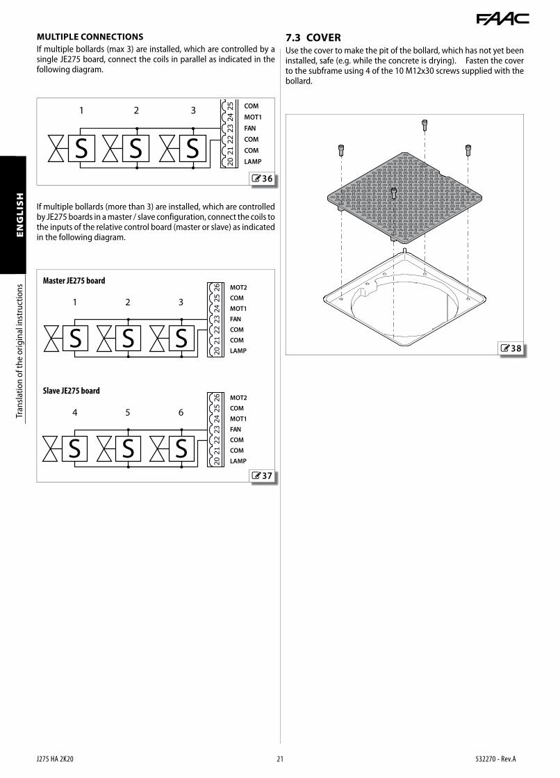
If multiple bollards (more than 3) are installed, which are controlled by JE275 boards in a master / slave configuration, connect the coils to the inputs of the relative control board (master or slave) as indicated in the following diagram.
Master JE275 board
Slave JE275 board
7.3 COVERUse the cover to make the pit of the bollard, which has not yet been installed, safe (e.g. while the concrete is drying). Fasten the cover to the subframe using 4 of the 10 M12x30 screws supplied with the bollard.
MULTIPLE CONNECTIONSIf multiple bollards (max 3) are installed, which are controlled by a single JE275 board, connect the coils in parallel as indicated in the following diagram.

FAAC S.p.A. Soc. Unipersonale
Via Calari, 10 - 40069 Zola Predosa - BOLOGNA - ITALY
Tel. +39 051 61724 - Fax +39 051 09 57 820
www.faac.it - www.faacgroup.com
J275 HA 2K20 22 532270 - Rev.A