VXE PVC-Csdt.com.vn/files/document//FIP_Ball_Valve_VXE_Series_CPVC.pdfVXE PVC-C 2 l dati del...
16
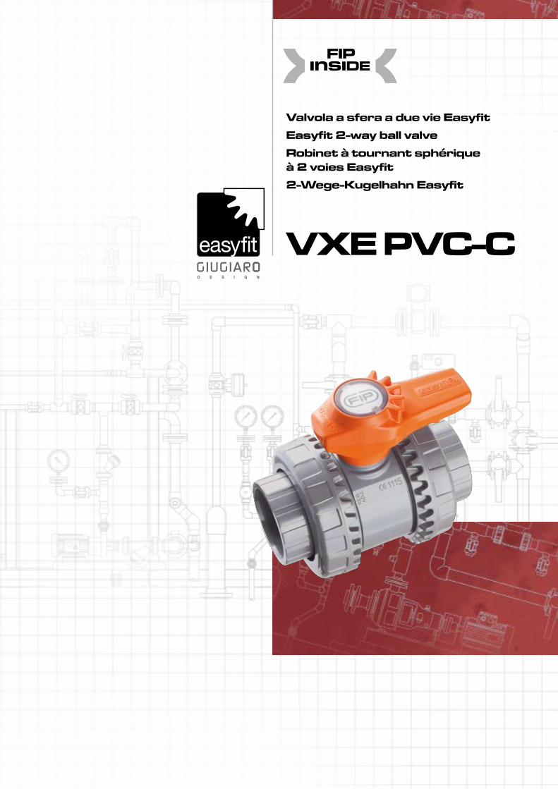
Valvola a sfera a due vie Easyfit Easyfit 2-way ball valve Robinet à tournant sphérique à 2 voies Easyfit 2-Wege-Kugelhahn Easyfit VXE PVC-C
Transcript of VXE PVC-Csdt.com.vn/files/document//FIP_Ball_Valve_VXE_Series_CPVC.pdfVXE PVC-C 2 l dati del...
Valvola a sfera a due vie EasyfitEasyfit 2-way ball valveRobinet à tournant sphérique à 2 voies Easyfit2-Wege-Kugelhahn Easyfit
VXE PVC-C
VXE PVC-C
2
l dati del presente prospetto sono forniti in buona fede. La FIP non si assume alcuna responsabilità su quei dati non direttamente derivati da norme internazionali. La FIP si riserva di apportarvi qualsiasi modifica.
The data given in this leaflet are offered in good faith. No liability can be accepted concerning technical data that are not directly covered by recognized international Standards. FIP reserves the right to carry out any modification to the products shown in this leaflet.
Les données contenues dans cette brochure sont fournies en bonne foi. FIP n’assume aucune responsabilité pour les données qui ne dérivent pas directe-ment des normes internationales.FIP garde le droit d’apporter toute mo-dification aux produits présentés dans cette brochure.
Alle Daten dieser Druckschrift urden nach bestem Wissen angegeben, jedoch besteht keine Verbindlichkeit, sofern sie nicht direkt internationalen Normen entnommen wurden. Die Änderung von Maßen oder Ausführungen bleibt FIP vorbehalten.
VXE PVC-C
3
FIP e Giugiaro Design hanno proget-tato e sviluppato VX Easyfit, l’inno-vativa valvola a sfera a smontaggio radiale con regolazione del serraggio delle ghiere, che consente una in-stallazione semplice e sicura per un servizio affidabile nel tempo.
• Gamma dimensionale da d 16 mm a d 63 mm, da R 3/8” a R 2”
• Sistema di giunzione per incollag-gio e per filettatura
• Resistenza a pressioni di esercizio fino a 16 bar a 20° C
• Nuovo sistema brevettato Easyfit: l’innovativo meccanismo basato sulla cinematica delle ruote dentate coniche che comanda la rotazione delle ghiere della valvola durante l’installazione. La maniglia mul-tifunzione Easyfit risulta partico-larmente utile nelle operazioni di manutenzione ove si operi in spazi limitati e di difficile accessibilità.
• Facile disinserimento radiale dall’impianto e conseguente rapida sostituzione degli O-ring e delle guarnizioni della sfera senza l’impie-go di alcun attrezzo
• Ingombro ridotto con quote di installazione secondo EN 1452 “short”. Completa intercambia-bilità con i precedenti modelli di valvole a sfera serie VX
• Possibilità di smontaggio delle tubazioni a valle con la valvola in posizione di chiusura
• Supporto delle tenute bloccato con possibilità di regolazione
• Maniglia ergonomica multifunzio-nale Easyfit biposizionabile con comando rotazione ghiere e chiave per regolazione delle tenute sfera. Completa di sistema di etichettatu-ra personalizzabile Easyfit
• Idoneità del PVC-C impiegato a venire in contatto con acqua po-tabile ed altre sostanze alimentari secondo le leggi vigenti
• Per maggiori informazioni visitare il sito: www.fipnet.it/easyfit
FIP and Giugiaro Design have desig-ned and developed VX Easyfit, the innovative true union gear ball valveintroducing an advanced method of installation for a long trouble free service.
• Size range from d 16 mm up to d 63 mm and from R 3/8” up to R 2”
• Jointing by solvent welding or thre-aded connections
• Maximum working pressure: 16 bar at 20° C• New patended Easyfit system:
based on the principle of the bevel gear pair has been applied to de-sign the mechanism that controls the rotation of the union nuts during the valve installation. The use of the Easyfit multifunctional handle is the best solution to carry out maintenence operations in narrow spaces with limited access to the valve location.
• Easy removal of the valve body from the system, allowing quick
replacement of O-rings and ball seats without additional equipment
• Compact design with true union installation dimensions according to EN 1452 “short”. Fully inter-changeable with the previous FIP ball valves VX series
• In the closed position the pipeline can be disconnected downstream from the valve without leakage
• Safe locked carrier with adjustment of ball seal
• Block with adjustment of ball seal• Easyfit hergonomic multifunctio-
nal handle with union nut rota-tion control and ball seat carrier adjustment wrench. Easyfit custom labelling system as standard
• FIP C-PVC is suitable for conveying foodstuffs and drinking water and meets the necessary standards and regulations
• For more information please visit our website:
www.fipnet.it/easyfit
FIP et Giugiaro Design ont conçu et développé la VX Easyfit, la vanne à boisseau sphérique raccords union innovatrice, introduisant une métho-de d’installation avancée pour un service fiable de longue durée.
• Gamme dimensionnelle de d 16 mm à d 63 mm, de R 3/8” à R 2”
• Jonction par collage aussi bien que par filetage
• Pression de service jusqu’à 16 bar à 20° C; pour les détails voir page suivante
• Nouveau système breveté Easyfit basé sur le principe des engre-nages coniques, appliqué pour la conception du mécanisme de contrôle de la rotation des écrous-union lors de l’installation de la vanne. L’utilisation de la poignée multifonctions Easyfit est la meil-leure solution pour les opérations de maintenance dans les espaces réduits, lorsque la vanne est diffici-lement accessible.
• Démontage radial du corps du ro-binet qui permet un rempla-cement rapide des joints O-ring et des au-tres garnitures, sans utiliser aucun outil
• Conception compacte avec dimensions de l’écrou union suivant EN 1452 série « court ». Entièrement interchangeable avec la précédente vanne à bille VX de FIP.
• En position fermée, le robinet per-met le démontage de l’installation en aval par rapport à la direction du flux
• Verrouillage de sécurité du siège amovible avec possibilité d’ajuste-ment.
• Poignée Easyfit ergonomique et multifonctions pour le serrage des écrous et l’ajustement du serrage.
Complète avec le Système de per-sonalisation Easyfit
• PVC-C de qualité alimentaire apte à l’utilisation avec l’eau potable et les aliments suivant les règlements en vigueur
• Pour avoir d’autres informations, visiter le site:
www.fipnet.it/easyfit
Valvola a sfera a due vie Easyfit
Easyfit 2-way ball valve
Robinet à tournant sphérique à 2 voies Easyfit
2-Wege-Kugelhahn Easyfit
FIP und Giugiaro Design haben VX Easyfit projektiert und entwickelt, der innovativer beidseitig verschrau-bter Kugelhahn, welcher eine fort-geschrittene Installationsmethode für einen störungsfreien Betrieb eingeführt hat.
• Größen von d 16 mm bis d 110 mm und von R 3/8” bis R 4”
• Mit Klebe- oder Gewindean-schlüssen
• Der maximale Betriebsdruck beträgt 16 bar bei 20° C. Weitere
Einzelheiten auf folgende Seite• Neues patentiertes Easyfit System:
beruhend auf dem Prinzip der Kegelgetriebe, der innovative Mechanismus kontrolliert während der Installation die Rotation der Überwurfmuttern der Armatur.
Der Multifunktionalhebel ist die beste Lösung für die Wartung in engem Raum, mit schwierigem Zugriff zur- Armatur.
• Der einfache Ausbau der Armatur aus dem Leitungssystem erlaubt den schnellen Wechsel von
O-Ringen oder Kugelsitzen ohne zusätzliches Werkzeug
• Kompaktes Design mit Dimensionen entsprechend der EN 1452 “short”.
Völlig austauschbar mit den vorherigen Kugelhahnmodelle VX.
• In geschlossener Stellung des Kugelhahns kann die drucklose Seite der Leitung gelöst werden
• Blockierter Dichtungsträger mit Justierungfähigkeit
• Easyfit ergonomischer Multifunktionalhebel mit Kontrolle der Ueberwurfmutterrotation und Schluessel fuer die Dichtungstraegerjustierung
• FIP PVC-C entspricht den gelten-den Vorschriften und ist für Komplett mit dem Anpassungsystem Easyfit Trinkwasser oder andere für den Verzehr bestimmte Medien
zugelassen• Für weitere Details schauen Sie auf
unsere Website: www.fipnet.it/easyfit

VXE PVC-C
4
Legenda
d diametro nominale esterno del tubo in mm
DN diametro nominale interno in mm
R dimensione nominale della filettatura in pollici
PN pressione nominale in bar (pressione max di esercizio a 20° C -
acqua)
g peso in grammi
PVC-C cloruro di polivinile surclorato
HIPVC PVC alto impatto
EPDM elastomero etilene pro-pilene
FPM (FKM) fluoroelastomero
PTFE politetrafluoroetilenePE polietilene
s spessore tubo in mm
SDR standard dimension ratio = d/s
d nominal outside diameter of the pipe in mm
DN nominal internal diameter in mm
R nominal size of the thread in inches
PN nominal pressure in bar (max. working pressure
at 20° C - water)
g weight in grams
C-PVC chlorinated polyvinyl chloride
HIPVC high impact PVC
EPDM ethylene propylene rubber
FPM (FKM) vinylidene fluoride rubber
PTFE polytetrafluoroethylenePE polyethylene
s wall thickness, mm
SDR standard dimension ratio = d/s
d diamètre éxtérieur nominal du tube en mm
DN diamètre nominal interieur en mm
R dimension nominale du filetage en pouces
PN pression nominale en bar (pression de service max à 20° C - eau)
g poids en grammes
PVC-C polyvinile de chlorure surchloré
HIPVC PVC haut impact
EPDM élastomère ethylène propylène
FPM (FKM) fluorélastomère de vinylidène
PTFE polytétrafluoroéthylènePE polyéthylène
s épaisseur du tube, mm
SDR standard dimension ratio = d/s
d Rohraußendurchmesser, mm
DN Nennweite, mm
R Gewinde (DIN 2999, T1)
PN Nenndruck, bar (max Betriebsdruck bei 20° C Wasser)
g Gewicht in Gramm
PVC-C polyvinylchlorid, chloriert
HIPVC hoch Einschlag
EPDM Ethylenpropylen-dienelastomer
FPM (FKM) Fluorelastomer
PTFE PolytetraflourethylenPE Polyethylen
s Wandstärke, mm
SDR standard dimension ratio = d/s
Easyfit è un marchio registrato di proprietà FIP
Easyfit is a registered trademark of FIP property
Easyfit ist eine registrierte Handelsmarke Eigentum von FIP
Easyfit est un mar-que enregistrée de proprieté de FIP
VXE PVC-C
5
Dati Tecnici
Technical Data
Données Techniques
Technische Daten
1
3
1
3
2
2
4
Nm5550454035302520151050
dR
201/2
253/4
321
4011/4
163/8
5011/2
632
mom
ento
di m
anov
ra -
torq
ue -
coup
le
de m
anoe
uvre
- Be
tätig
ungs
mom
ente
portata - flow rate- débit - Durchflußmengepe
rdita
di c
arico
- pr
essu
re lo
st -
perte
de
char
ge -
Druc
kver
lust
DN 15÷50bar
16
14
12
10
8
6
4
2
0
-20 0 20 40 °C60 10080
pres
sione
di e
serc
izio
- wor
king
pre
ssur
epr
essio
n de
ser
vice
- Bet
riebs
druc
k
temperatura di esercizio - working temperaturetempérature de service - Betriebstemperatur
4032
1100
3225
770
2520
385
5040
1750
2015
200
161080
dDN
kv100
6350
3400
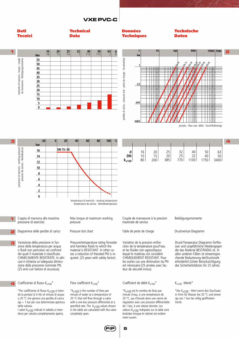
Coppia di manovra alla massima pressione di esercizio
Max torque at maximum working pressure
Couple de manoeuvre à la pression maximale de service
Betätigungsmomente
Diagramma delle perdite di carico Pressure lost chart Table de perte de charge Druckverlust-Diagramm
Variazione della pressione in fun-zione della temperatura per acqua o fluidi non pericolosi nei confronti dei quali il materiale è classificato CHIMICAMENTE RESISTENTE. In altri casi è richiesta un’adeguata diminu-zione della pressione nominale PN. (25 anni con fattore di sicurezza).
Pressure/temperature rating forwater and harmless fluids to which the material is RESISTANT. In other ca-ses a reduction of therated PN is re-quired. (25 years with safety factor).
Variation de la pression enfon-ction de la température pourl’eau et les fluides non agressifspour lequel le matériau est considéré CHIMIQUEMENT RESISTANT. Pour les outres cas une diminution du PN est nécessaire.(25 années avec fac-teur de sécurité inclus).
Druck/Temperatur-Diagramm fürWa-sser und ungefährliche Mediengegen die das Material BESTÄNDIG ist. In allen anderen Fällen ist eineentspre-chende Reduzierung derDruckstufe erforderlich.(Unter Berücksichtigung des Sicherheitsfaktors für 25 Jahre).
Coefficiente di flusso Kv100*
*Per coefficiente di flusso Kv100 si inten-de la portata Q in litri al minuto di acqua a 20 °C che genera una perdita di carico ∆p = 1 bar per una determinata apertura della valvola.I valori Kv100 indicati in tabella si inten-dono per valvola completamente aperta.
Flow coefficient Kv100*
*Kv100 is the number of litres per minute of water at a temperature of 20 °C that will flow through a valve with a one-bar pressure differential at a specified rate. The Kv100 values shown in the table are calculated with tha valve completely open.
Coefficient de débit Kv100*
*Kv100 est le nombre de litres par minute d’eau, à une température de 20 °C, qui d’écoule dans une vanne de régulation avec une pression différentielle de 1 bar, à une vitesse donnée. Les valeurs Kv100 indiquées sur la table sont évaluées lorsque le robinet est entière-ment ouvert.
Kv100 -Werte*
*Der Kv100 - Wert nennt den Durchsatz in l/min für Wasser bei 20 °C und einem ∆p von 1 bar bei völlig geöffnetem Ventil.
4

VXE PVC-C
6
Dimensioni Dimensions Dimensions Dimensionen
La FIP ha approntato una gamma di valvole a sfera, i cui attacchi sono in accordo con le seguenti norme:Incollaggio: ISO 727, ISO 15493, ASTM F439,accoppiabili con tubi secondoISO 15493, DIN 8079/8080, ASTM D 1785/76.Filettatura:ASTM D 2464/76, ASA ANSI B1.20.1.
FIP a réalisé une gamme compléte de robinet à tournant sphérique dont les embouts sont conformes aux normes suivantes:Collage: ISO 727, ISO 15493, ASTM F439,assemblés avec des tubes selon ISO 15493, DIN 8079/8080, ASTM D 1785/76.Filetage:ASTM D 2464/76, ANSI B1.20.1.
Die Kugelhahnreihe entspricht mit ihren Anschlüßmöglichkeiten folgenden Normen:Klebeanschluß: ISO 727, ISO 15493, ASTM F439, für Rohre nach ISO 15493, DIN 8079/8080, ASTM D 1785/76.Gewindeverbindung: ASTM D 2464/76, ANSI B1.20.1.
FIP have produced a complete range of ball valves whose couplings comply with the following standards:Solvent welding: ISO 727, ISO 15493, ASTM F439,coupling to pipes complying with ISO 15493, DIN 8079/8080, ASTM D 1785/76.Threaded couplings: ASTM D 2464/76, ANSI B1.20.1.
VXEICVALVOLA A DUE VIE Easyfitcon attacchi femmina per incollaggio, serie metrica
Easyfit 2 WAY BALL VALVEwith metric series plain female ends for solvent welding
ROBINET À 2 VOIS Easyfit avec embouts femelles à coller, série métrique
2-WEGE KUGELHAHN Easyfitmit Muffe nach ISO
d
202532405063
PN
161616161616
DN
152025324050
L
161922263138
Z
505359687798
H
8291
103120139174
E
54637285
100118
B
4962718292
110
C
647887
102109133
C1
202327303339
g
175260365565795
1325
R
1/2”3/4”
1”1 1/4”1 1/2”
2”
PN
161616161616
DN
152025324050
L
17,818
22,625,124,729,6
Z
54,457
64,876,881,6
101,8
H
9093
110127131161
E
54637285
100118
B
4962718292
110
C
647887
102109133
C1
202327303339
g
175260365565795
1325
VXENCVALVOLA A DUE VIE Easyfitcon attacchi femmina filettatura NPT
2-WAY BALL VALVE Easyfitwith NPT threaded female ends
ROBINET À 2 VOIS Easyfitavec embouts femelles taraudé NPT
2-WEGE KUGELHAHN Easyfit mit Gewindemuffen nach NPT
VXEACVALVOLA A DUE VIE Easyfitcon attacchi femmina, serie ASTM
2-WAY BALL VALVE Easyfitwith ASTM series plain female ends
ROBINET À 2 VOIS Easyfitavec embouts femelles, série ASTM
2-WEGE KUGELHAHN Easyfit mit Muffe nach ASTM
d
1/2”3/4”
1”1 1/4”1 1/2”
2”
PN
161616161616
DN
152025324050
L
22,525,528,7
3235
38,2
Z
5154
59,57277
97,6
H
96105117136147174
E
54637285
100118
B
4962718292
110
C
647887
102109133
C1
202327303339
g
175260365565795
1325
VXE PVC-C
7
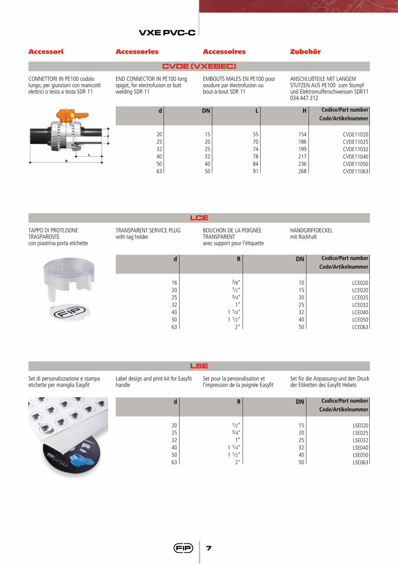
Set di personalizzazione e stampa etichette per maniglia Easyfit
Label design and print kit for Easyfit handle
Set pour la personalisation et l’impression de la poignée Easyfit
Set für die Anpassung und den Druck der Etiketten des Easyfit Hebels
LSE
d
202532405063
R
1/2”3/4”
1”1 1/4”1 1/2”
2”
DN
152025324050
Codice/Part number
Code/Artikelnummer
LSE020LSE025LSE032LSE040LSE050LSE063
Accessori Accessories Accessoires Zubehör
CONNETTORI IN PE100 codolo lungo, per giunzioni con manicotti elettrici o testa a testa SDR 11
END CONNECTOR IN PE100 long spigot, for electrofusion or butt welding SDR 11
EMBOUTS MALES EN PE100 poursoudure par électrofusion oubout-à-bout SDR 11
ANSCHLUßTEILE MIT LANGEM STUTZEN AUS PE100 zum Stumpf und Elektromuffenschweissen SDR11034.447.312
CVDE (VXEBEC)
d
202532405063
DN
152025324050
L
557074788491
H
154186199217236268
Codice/Part number
Code/Artikelnummer
CVDE11020CVDE11025CVDE11032CVDE11040CVDE11050CVDE11063
TAPPO DI PROTEZIONE TRASPARENTEcon piastrina porta etichette
TRANSPARENT SERVICE PLUGwith tag holder
BOUCHON DE LA POIGNéE TRANSPARENT avec support pour l’étiquette
HANDGRIFFDECKEL mit Rückhalt
LCE
d
16202532405063
R
3/8”1/2”3/4”
1”1 1/4”1 1/2”
2”
DN
10152025324050
Codice/Part number
Code/Artikelnummer
LCE020LCE020LCE025LCE032LCE040LCE050LCE063
VXE PVC-C
8
Fig. 1 Fig. 2
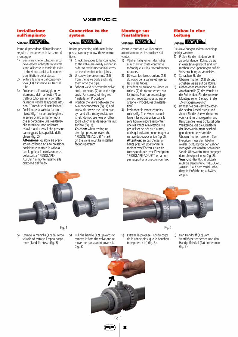
Installazione sull’impianto
Connection to the system
Montage sur l’installation
Einbau in eineLeitung
Sistema
Prima di procedere all’installazione seguire attentamente le istruzioni di montaggio:1) Verificare che le tubazioni a cui
deve essere collegata la valvola siano allineate in modo da evita-re sforzi meccanici sulle connes-sioni filettate della stessa.
2) Svitare le ghiere dal corpo val-vola (13) e inserirle sui tratti di tubo.
3) Procedere all’incollaggio o av-vitamento dei manicotti (7) sui tratti di tubo: per una corretta
giunzione vedere le apposite istru-zioni “Procedure di installazione”.
4) Posizionare la valvola fra i ma-nicotti (fig. 1) e serrare le ghiere in senso orario a mano fino a che si percepisce una resistenza alla rotazione; non utilizzare chiavi o altri utensili che possano danneggiare la superficie delle ghiere (fig. 2).
Attenzione: qualora sia previ-sto un collaudo ad alta pressione posizionare sempre la valvola con la ghiera in corrispondenza della scritta “REGOLARE-ADJUST” a monte rispetto alla direzione del fluido.
System
Before proceeding with installation please carefully follow these instruc-tions:1) Check the pipes to be connected
to the valve are axially aligned in order to avoid mechanical stress on the threaded union joints.
2) Unscrew the union nuts (13) from the valve body and slide them onto the pipe.
3) Solvent weld or screw the valve end connectors (7) onto the pipe ends. For correct jointing see “Installation Procedure”.
4) Position the valve between the two endconnectors (fig. 1) and screw clockwise the union nuts by hand till a rotary resistance is felt; do not use keys or other tools which may damage the nut surface (fig. 2).
Caution: when testing un-der high pressure levels, the “REGOLARE-ADJUST” mark on the valve must be installed facing upstream
Système
Avant le montage veuillez suivre attentivement les instructions sui-vantes:1) Vérifier l’alignement des tubes
afin d’ éviter toute contrainte mécanique sur les raccordements taraudés.
2) Dévisser les écrous-unions (13) du corps de la vanne et insérez-les sur les tubes.
3) Procéder au collage ou visser les collets (7) de raccordement sur les tubes. Pour un assemblage correct, reportez-vous au para-graphe « Procédures d’installa-tion”.
4) Positionner la vanne entre les collets (fig. 1) et visser manuel-lement les écrous union dans le sens horaire jusqu’à rencontrer une résistance à la rotation. Ne pas utiliser de clés ou d’autres outils qui puissent endommager la surface des écrous union (fig. 2).
Attention: en cas d’essai à haute pression positionner le robinet avec l’écrou située en correspondance avec l’inscription “REGOLARE-ADJUST” en amont par rapport à la direction du flux.
System
Die Anweisungen sollten unbedingt gefolgt werden:1) Prüfen Sie die mit dem Ventil
zu verbindenden Rohre, ob sie in einer Linie gebracht sind, um mechanische Spannungen auf die Verschraubung zu vermeiden.
2) Schrauben Sie die Überwurfmuttern (13) ab und schieben Sie sie auf die Rohre.
3) Kleben oder schrauben Sie die Anschlussteile (7) des Ventils an die Rohrenden. Für die korrekte Montage sehen Sie auch in die „Montageanweisung“.
4) Bringen Sie das Ventil zwischen die beiden Anschlussteile und ziehen Sie die Überwurfmuttern von Hand im Uhrzeigersinn an. Benutzen Sie keine Schlüssel oder Werkzeuge, die die Oberfläche der Überwurfmuttern beschädi-gen können. Jetzt sind die Überwurfmuttern arretiert. Zum Freigeben muss der Hebel in axialer Richtung von den Zähnen weg gedrückt werden. Schrauben Sie die Überwurfmuttern entgegen dem Uhrzeigersinn los (fig. 2).
Vorsicht: -Bei Hochdrucktests muß die Beschriftung “REGOLARE -ADJUST” auf dem Ventil unbe-dingt in Flußrichtung aufwärts zeigen.
5) Estrarre la maniglia (12) dal corpo valvola ed estrarre il tappo traspa-rente (1a) dalla stessa (fig. 3)
5) Pull the handle (12) upwards to remove it from the valve and re-move the transparent cover (1a) (fig. 3)
5) Extraire la poignée (12) du corps de la vanne ainsi que le bouchon transparent (1a) (fig. 3).
5) Den Handgriff (12) vom Ventilkörper entfernen und den Handgriffdeckel (1a) entnehmen (fig. 3).
Fig. 3
VXE PVC-C
9
Nota: la prima volta che si utilizza il sistema di serraggio Easyfit, si con-siglia di provare a svitare la ghiera a mano una volta serrata, per consta-tare l’efficacia di tale meccanismo: unpiccolo sforzo applicato alla maniglia sviluppa una coppia molto superiore a quella di un serraggio manuale.E’ anche possibile, attraverso un set di apposite bussole, fornite da FIP, effettuare il serraggio delle ghiere utilizzando una chiave dinamometri-ca per quantificare gli sforzi e quindi monitorare gli stress applicati allefilettature termoplastiche in accordo alle indicazioni di installazione ripor-tate nelle istruzioni allegate al set stesso.
Note: the first time the Easyfit sy-stem is used, it is advised to try to lo-ose by hand the nut just tightened, in order to realize the efficiency of the mechanism: e low input torque on the handle generates a much higher output torque than a simple hand tightening. It is also possible, using the dedicate bushes set, supplied by FIP, to perform the nut tightening with a dynamometric key, in order to measure and control the force andthe stress applied on the thermo-plastic threads according to the installation guideline supplied with the bushes set.
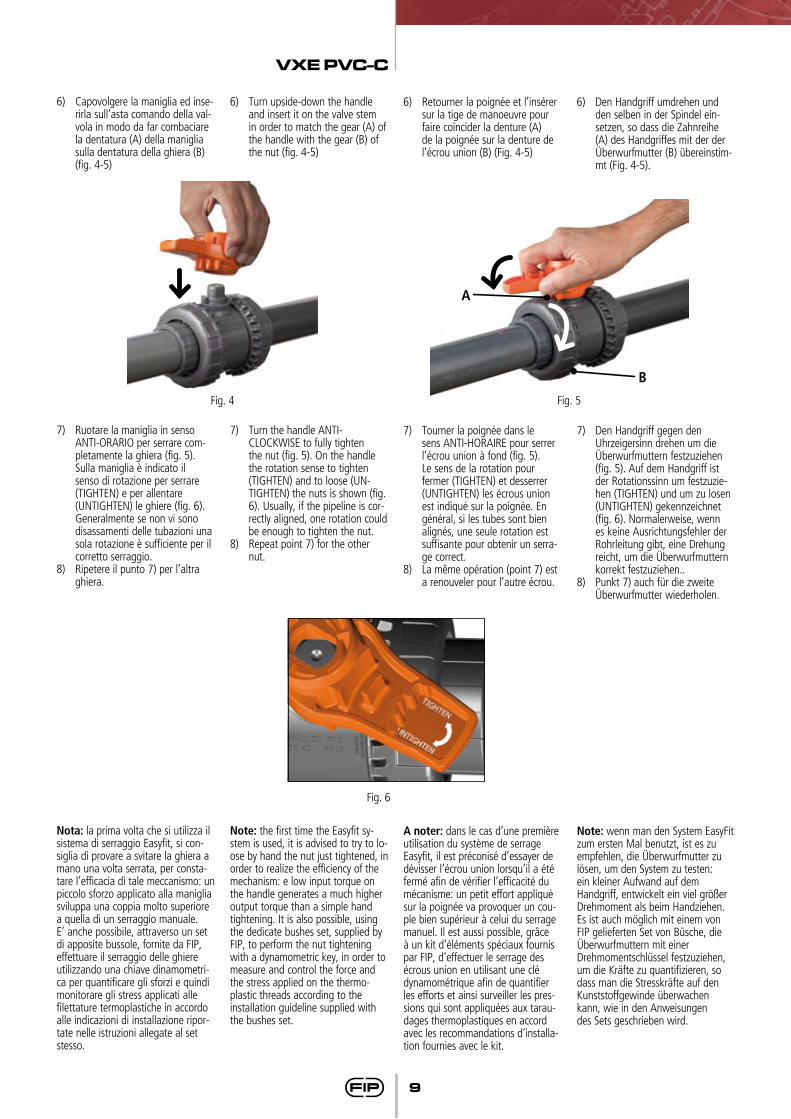
6) Capovolgere la maniglia ed inse-rirla sull’asta comando della val-vola in modo da far combaciare la dentatura (A) della maniglia sulla dentatura della ghiera (B) (fig. 4-5)
7) Ruotare la maniglia in senso ANTI-ORARIO per serrare com-pletamente la ghiera (fig. 5).
Sulla maniglia è indicato il senso di rotazione per serrare (TIGHTEN) e per allentare (UNTIGHTEN) le ghiere (fig. 6). Generalmente se non vi sono disassamenti delle tubazioni una sola rotazione è sufficiente per il corretto serraggio.
8) Ripetere il punto 7) per l’altra ghiera.
6) Turn upside-down the handle and insert it on the valve stem in order to match the gear (A) of the handle with the gear (B) of the nut (fig. 4-5)
7) Turn the handle ANTI-CLOCKWISE to fully tighten the nut (fig. 5). On the handle the rotation sense to tighten (TIGHTEN) and to loose (UN-TIGHTEN) the nuts is shown (fig. 6). Usually, if the pipeline is cor-rectly aligned, one rotation could be enough to tighten the nut.
8) Repeat point 7) for the other nut.
A noter: dans le cas d’une première utilisation du système de serrage Easyfit, il est préconisé d’essayer de dévisser l’écrou union lorsqu’il a étéfermé afin de vérifier l’efficacité du mécanisme: un petit effort appliqué sur la poignée va provoquer un cou-ple bien supérieur à celui du serrage manuel. Il est aussi possible, grâce à un kit d’éléments spéciaux fournis par FIP, d’effectuer le serrage des écrous union en utilisant une clédynamométrique afin de quantifier les efforts et ainsi surveiller les pres-sions qui sont appliquées aux tarau-dages thermoplastiques en accordavec les recommandations d’installa-tion fournies avec le kit.
Note: wenn man den System EasyFit zum ersten Mal benutzt, ist es zu empfehlen, die Überwurfmutter zu lösen, um den System zu testen: ein kleiner Aufwand auf dem Handgriff, entwickelt ein viel größer Drehmoment als beim Handziehen.Es ist auch möglich mit einem von FIP gelieferten Set von Büsche, dieÜberwurfmuttern mit einer Drehmomentschlüssel festzuziehen, um die Kräfte zu quantifizieren, so dass man die Stresskräfte auf den Kunststoffgewinde überwachen kann, wie in den Anweisungendes Sets geschrieben wird.
6) Retourner la poignée et l’insérer sur la tige de manoeuvre pour faire coïncider la denture (A) de la poignée sur la denture de l’écrou union (B) (Fig. 4-5)
7) Tourner la poignée dans le sens ANTI-HORAIRE pour serrer l’écrou union à fond (fig. 5).
Le sens de la rotation pour fermer (TIGHTEN) et desserrer (UNTIGHTEN) les écrous union est indiqué sur la poignée. En général, si les tubes sont bien alignés, une seule rotation est suffisante pour obtenir un serra-ge correct.
8) La même opération (point 7) est a renouveler pour l’autre écrou.
6) Den Handgriff umdrehen und den selben in der Spindel ein-setzen, so dass die Zahnreihe (A) des Handgriffes mit der der Überwurfmutter (B) übereinstim-mt (Fig. 4-5).
7) Den Handgriff gegen den Uhrzeigersinn drehen um die Überwurfmuttern festzuziehen (fig. 5). Auf dem Handgriff ist der Rotationssinn um festzuzie-hen (TIGHTEN) und um zu losen (UNTIGHTEN) gekennzeichnet (fig. 6). Normalerweise, wenn es keine Ausrichtungsfehler der Rohrleitung gibt, eine Drehung reicht, um die Überwurfmuttern korrekt festzuziehen..
8) Punkt 7) auch für die zweite Überwurfmutter wiederholen.
Fig. 6
Fig. 4
A
B
Fig. 5
VXE PVC-C
10
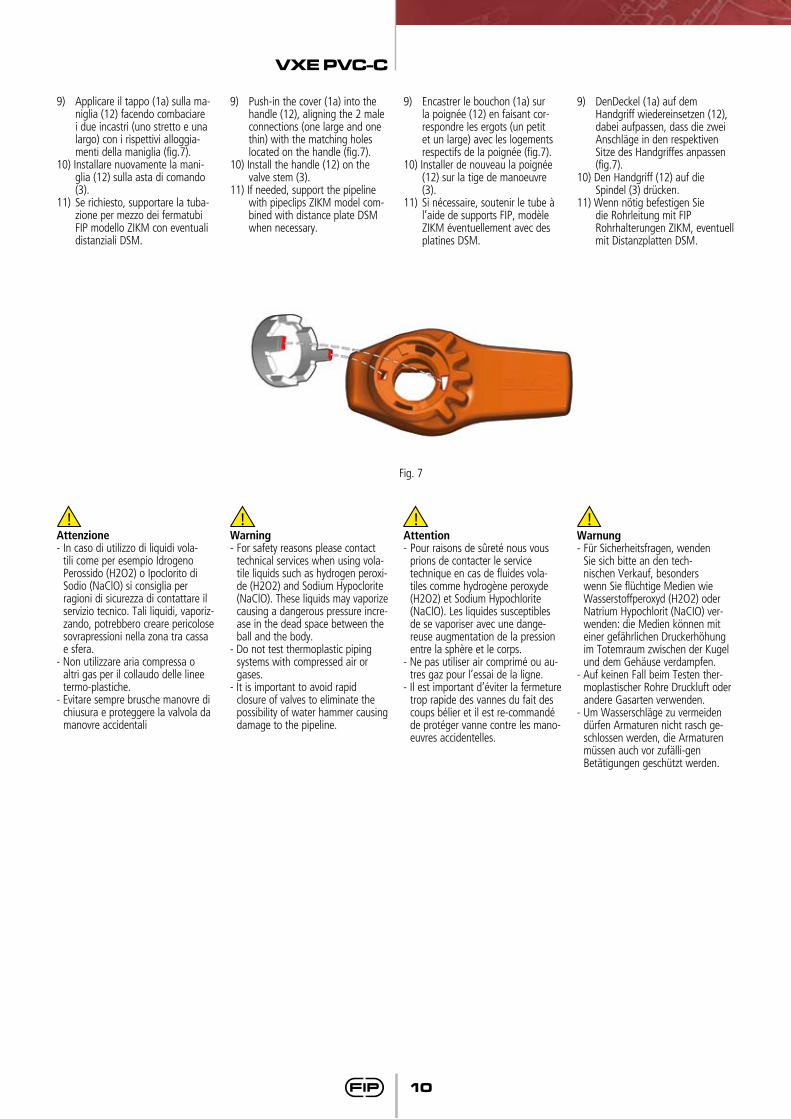
9) Applicare il tappo (1a) sulla ma-niglia (12) facendo combaciare i due incastri (uno stretto e una largo) con i rispettivi alloggia-menti della maniglia (fig.7).
10) Installare nuovamente la mani-glia (12) sulla asta di comando (3).
11) Se richiesto, supportare la tuba-zione per mezzo dei fermatubi FIP modello ZIKM con eventuali distanziali DSM.
9) Push-in the cover (1a) into the handle (12), aligning the 2 male connections (one large and one thin) with the matching holes located on the handle (fig.7).
10) Install the handle (12) on the valve stem (3).
11) If needed, support the pipeline with pipeclips ZIKM model com-bined with distance plate DSM when necessary.
9) Encastrer le bouchon (1a) sur la poignée (12) en faisant cor-respondre les ergots (un petit et un large) avec les logements respectifs de la poignée (fig.7).
10) Installer de nouveau la poignée (12) sur la tige de manoeuvre (3).
11) Si nécessaire, soutenir le tube à l’aide de supports FIP, modèle ZIKM éventuellement avec des platines DSM.
9) DenDeckel (1a) auf dem Handgriff wiedereinsetzen (12), dabei aufpassen, dass die zwei Anschläge in den respektiven Sitze des Handgriffes anpassen (fig.7).
10) Den Handgriff (12) auf die Spindel (3) drücken.
11) Wenn nötig befestigen Sie die Rohrleitung mit FIP Rohrhalterungen ZIKM, eventuell mit Distanzplatten DSM.
Fig. 7
Attenzione - In caso di utilizzo di liquidi vola-
tili come per esempio Idrogeno Perossido (H2O2) o Ipoclorito di Sodio (NaClO) si consiglia per ragioni di sicurezza di contattare il servizio tecnico. Tali liquidi, vaporiz-zando, potrebbero creare pericolose sovrapressioni nella zona tra cassa e sfera.
- Non utilizzare aria compressa o altri gas per il collaudo delle linee termo-plastiche.
- Evitare sempre brusche manovre di chiusura e proteggere la valvola da manovre accidentali
Warning- For safety reasons please contact
technical services when using vola-tile liquids such as hydrogen peroxi-de (H2O2) and Sodium Hypoclorite (NaClO). These liquids may vaporize causing a dangerous pressure incre-ase in the dead space between the ball and the body.
- Do not test thermoplastic piping systems with compressed air or gases.
- It is important to avoid rapid closure of valves to eliminate the possibility of water hammer causing damage to the pipeline.
Attention - Pour raisons de sûreté nous vous
prions de contacter le service technique en cas de fluides vola-tiles comme hydrogène peroxyde (H2O2) et Sodium Hypochlorite (NaClO). Les liquides susceptibles de se vaporiser avec une dange-reuse augmentation de la pression entre la sphère et le corps.
- Ne pas utiliser air comprimé ou au-tres gaz pour l’essai de la ligne.
- Il est important d’éviter la fermeture trop rapide des vannes du fait des coups bélier et il est re-commandé de protéger vanne contre les mano-euvres accidentelles.
Warnung - Für Sicherheitsfragen, wenden
Sie sich bitte an den tech-nischen Verkauf, besonders wenn Sie flüchtige Medien wie Wasserstoffperoxyd (H2O2) oder Natrium Hypochlorit (NaCIO) ver-wenden: die Medien können mit einer gefährlichen Druckerhöhung im Totemraum zwischen der Kugel und dem Gehäuse verdampfen.
- Auf keinen Fall beim Testen ther-moplastischer Rohre Druckluft oder andere Gasarten verwenden.
- Um Wasserschläge zu vermeiden dürfen Armaturen nicht rasch ge-schlossen werden, die Armaturen müssen auch vor zufälli-gen Betätigungen geschützt werden.
VXE PVC-C
11
Smontaggio Disassembly Démontage Demontage1) Isolare la valvola dalla linea (to-
gliere la pressione e svuotare la tubazione)
2) Svitare completamente le ghiere (13) dal corpo valvola (per fare questa operazione è consigliabile utilizzare il meccanismo Easyfit presente sulle ghiere impiegando la maniglia come attrezzo. Vedi sezione Easyfit di queste istru-zioni) e sfilare lateralmente la valvola.
3) Prima di smontare la valvola oc-corre drenare eventuali residui di liquido riamasti all’interno apren-do a 45° la valvola in posizione verticale; bisogna raccogliere la sostanza.
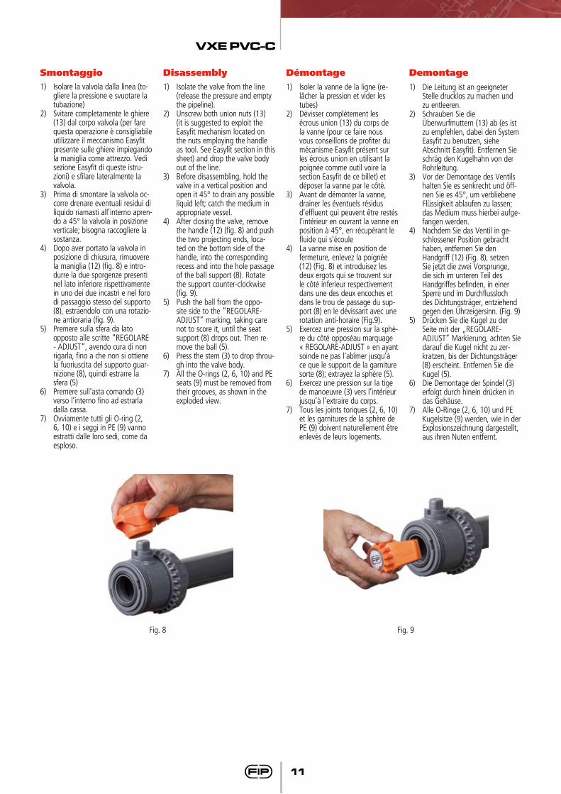
4) Dopo aver portato la valvola in posizione di chiusura, rimuovere la maniglia (12) (fig. 8) e intro-durre la due sporgenze presenti nel lato inferiore rispettivamente in uno dei due incastri e nel foro di passaggio stesso del supporto (8), estraendolo con una rotazio-ne antioraria (fig. 9).
5) Premere sulla sfera da lato opposto alle scritte “REGOLARE - ADJUST”, avendo cura di non rigarla, fino a che non si ottiene la fuoriuscita del supporto guar-nizione (8), quindi estrarre la sfera (5)
6) Premere sull’asta comando (3) verso l’interno fino ad estrarla dalla cassa.
7) Ovviamente tutti gli O-ring (2, 6, 10) e i seggi in PE (9) vanno estratti dalle loro sedi, come da esploso.
1) Isolate the valve from the line (release the pressure and empty the pipeline).
2) Unscrew both union nuts (13) (it is suggested to exploit the Easyfit mechanism located on the nuts employing the handle as tool. See Easyfit section in this sheet) and drop the valve body out of the line.
3) Before disassembling, hold the valve in a vertical position and open it 45° to drain any possible liquid left; catch the medium in
appropriate vessel.4) After closing the valve, remove
the handle (12) (fig. 8) and push the two projecting ends, loca-ted on the bottom side of the handle, into the corresponding recess and into the hole passage of the ball support (8). Rotate the support counter-clockwise (fig. 9).
5) Push the ball from the oppo-site side to the “REGOLARE-ADJUST” marking, taking care not to score it, until the seat support (8) drops out. Then re-move the ball (5).
6) Press the stem (3) to drop throu-gh into the valve body.
7) All the O-rings (2, 6, 10) and PE seats (9) must be removed from their grooves, as shown in the exploded view.
1) lsoler la vanne de la ligne (re-lâcher la pression et vider les tubes)
2) Dévisser complètement les écrous union (13) du corps de la vanne (pour ce faire nous vous conseillons de profiter du mécanisme Easyfit présent sur les écrous union en utilisant la poignée comme outil voire la section Easyfit de ce billet) et déposer la vanne par le côté.
3) Avant de démonter la vanne, drainer les éventuels résidus d’effluent qui peuvent être restés l’intérieur en ouvrant la vanne en position à 45°, en récupérant le fluide qui s’écoule
4) La vanne mise en position de fermeture, enlevez la poignée (12) (Fig. 8) et introduisez les deux ergots qui se trouvent sur le côté inferieur respectivement dans une des deux encoches et dans le trou de passage du sup-port (8) en le dévissant avec une rotation anti-horaire (Fig.9).
5) Exercez une pression sur la sphè-re du côté opposéau marquage « REGOLARE-ADJUST » en ayant soinde ne pas l’abîmer jusqu’à ce que le support de la garniture sorte (8); extrayez la sphère (5).
6) Exercez une pression sur la tige de manoeuvre (3) vers l’intérieur jusqu’à l’extraire du corps.
7) Tous les joints toriques (2, 6, 10) et les garnitures de la sphère de PE (9) doivent naturellement être enlevés de leurs logements.
1) Die Leitung ist an geeigneter Stelle drucklos zu machen und zu entleeren.
2) Schrauben Sie die Überwurfmuttern (13) ab (es ist zu empfehlen, dabei den System Easyfit zu benutzen, siehe Abschnitt Easyfit). Entfernen Sie schräg den Kugelhahn von der Rohrleitung.
3) Vor der Demontage des Ventils halten Sie es senkrecht und öff-nen Sie es 45°, um verbliebene Flüssigkeit ablaufen zu lassen; das Medium muss hierbei aufge-fangen werden.
4) Nachdem Sie das Ventil in ge-schlossener Position gebracht haben, entfernen Sie den Handgriff (12) (Fig. 8), setzen Sie jetzt die zwei Vorsprunge, die sich im unteren Teil des Handgriffes befinden, in einer Sperre und im Durchflussloch des Dichtungsträger, entziehend gegen den Uhrzeigersinn. (Fig. 9)
5) Drücken Sie die Kugel zu der Seite mit der „REGOLARE-ADJUST” Markierung, achten Sie darauf die Kugel nicht zu zer-kratzen, bis der Dichtungsträger (8) erscheint. Entfernen Sie die Kugel (5).
6) Die Demontage der Spindel (3) erfolgt durch hinein drücken in das Gehäuse.
7) Alle O-Ringe (2, 6, 10) und PE Kugelsitze (9) werden, wie in der Explosionszeichnung dargestellt, aus ihren Nuten entfernt.
Fig. 8 Fig. 9

VXE PVC-C
12
Montaggio Assembly Montage Montage1) Tutti gli O-ring (2, 6, 10) vanno
inseriti nelle loro sedi, come da esploso.
2) Inserire l’asta comando (3) dall’interno della cassa (4).
3) Inserire le guarnizioni in PE (9) nella sedi della cassa (4) e del supporto (8).
4) Inserire la sfera (5).5) Inserire nella cassa il supporto
(8) e avvitare in senso orario ser-vendosi della maniglia (12) fino a battuta.
6) Inserire la valvola tra i manicotti (7) e serrare le ghiere (13) utiliz-zando il sistema EASYFIT, aven-do cura che gli O-ring di tenuta di testa (10) non fuoriescano dalle sedi.
7) La maniglia (12) va posizionata sull’asta comando (3).
1) All the O-rings (2, 6, 10) must be inserted in their grooves as shown in the exploded view.
2) Insert the stem (3) from inside the valve body (4).
3) Place the PE seats (9) in its hou-sing located in the valve body (4) and in the support (8).
4) lnsert the ball (5).5) Screw completely the support (8)
into the body using the handle (12).
6) lnsert the valve in between the end connectors (7) and tighten the union nuts (13) with the EASYFIT system, taking care that the socket O-rings (10) do not come out of their grooves.
7) Press the handle (12) onto the stem (3).
1) Tous les joints toriques (2, 6,10) doivent être insérés dans leur logement, suivant l’éclaté.
2) Insérer la tige de manouvre (3) dans le corps en passant par l’intérieur (4).
3) Insérer la garniture en PE (9) dans le siège du corps (4) et du support (8).
4) Insérer la sphère (5)5) Insérer dans le corps le support
(8) et visser en direction horaire en utilisant la poignée (12) ap-propriée jusqu’à la butée.
6) Insérer la vanne entre les collets (7) et serrer les écrous union (13) en utilisant le système EASYFIT et en contrôlant que les Joint du collet (10) ne sortent pas de leur logements.
7) La poignée (12) doit être logée sur la tige de manoeuvre (3).
1) Alle in der Explosionszeichnung dargestellten O-Ringe (2, 6, 10) müssen bei der Montage in die entsprechenden Nuten einlegt werden.
2) Die Spindel (3) kann nur von der Innenseite des Gehäuses (4) ein-gesetzt werden. 3 Die PE-Sitze (9) in den Dichtungsträger (8) einsetzen, der im Ventilgehäuse (4) sitzt.
4) Danach ist die Kugel (6) zu mon-tieren.
5) Der Dichtungsträger (8) ist in das Gehäuse, unter Zuhilfenahme des Handgriffes (12) im Uhrzeigersinn, einzuschrauben (fig.10).
6) Den Kugelhahn zwischen den Anschlussteile (7) stellen und die Überwurfmuttern (13) mit den System EASYFIT montieren, wobei zu beachten ist, dass die O-Ringe (10) in den Nuten blei-ben.
7) Den Handhebel (2) auf die Spindel (3) drücken.
Nota: è consigliabile nelle operazioni di montaggio, lubrificare le guarni-zioni in gomma. A tale proposito si ricorda la non idoneità all’uso deglioli minerali, che sono aggressivi per la gomma EPDM.
Note: when assembling the valve components, it is advisable to lubri-cate the O-rings. Do not use mineral oils as they attack EPDM rubber.
Note: avant l’opération de montage, nous vous conseillons de lubrifier les joints en caoutchouc. Nous vous rappelons que les huiles minérales, agressives pour le caoutchouc éthylè-nepropylène, sont déconseillées.
Hinweis: Bei der Montage ist es ratsam die Gummidichtungen zu schmieren. Dabei ist zu beachten, dass Mineralöle nicht geeignet sind, da die-se EPDM- Gummi schädigen.
VXE PVC-C
13
Personalizzare VX Easyfit
CustomizeVX Easyfit
PersonaliserVX Easyfit
CustomizeVX Easyfit
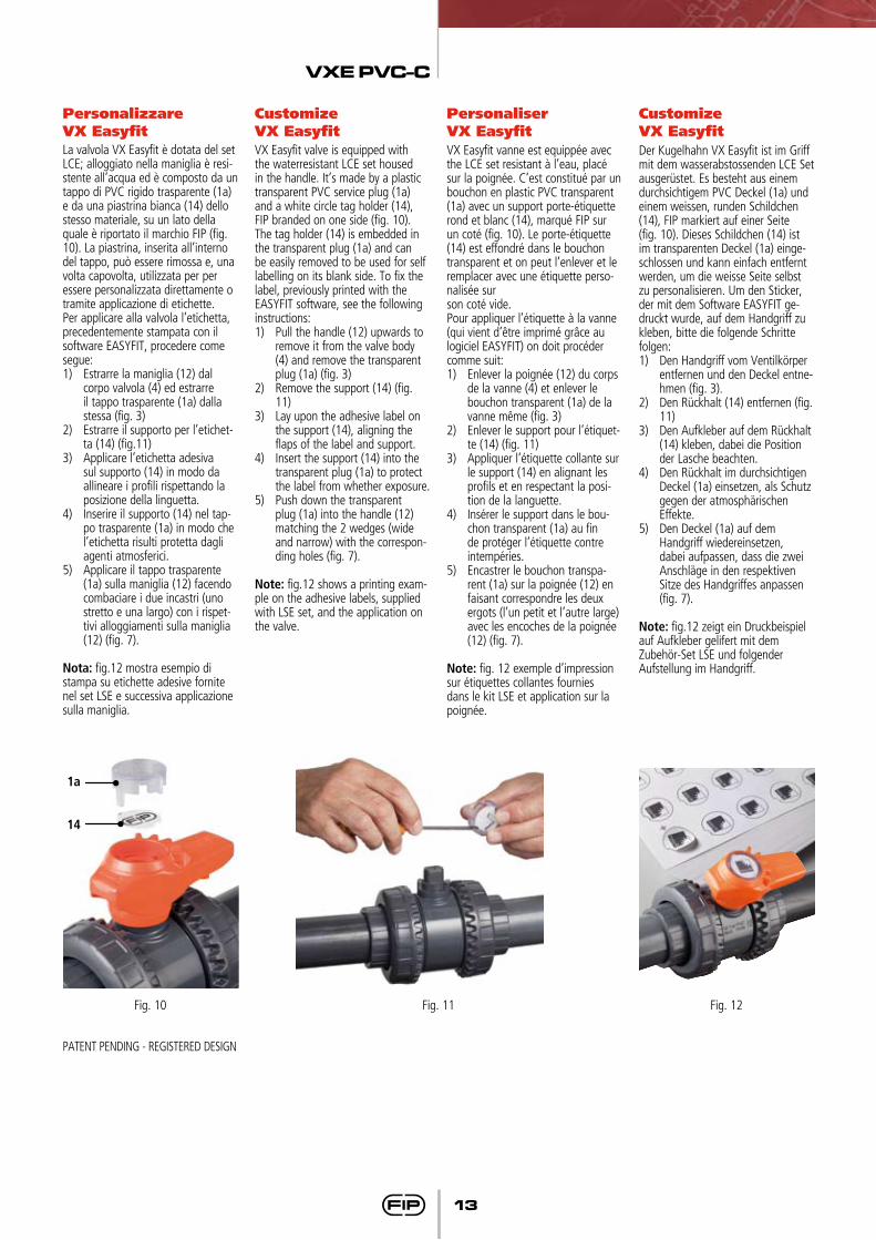
La valvola VX Easyfit è dotata del set LCE; alloggiato nella maniglia è resi-stente all’acqua ed è composto da un tappo di PVC rigido trasparente (1a) e da una piastrina bianca (14) dello stesso materiale, su un lato della quale è riportato il marchio FIP (fig. 10). La piastrina, inserita all’interno del tappo, può essere rimossa e, una volta capovolta, utilizzata per per essere personalizzata direttamente o tramite applicazione di etichette.Per applicare alla valvola l’etichetta, precedentemente stampata con il software EASYFIT, procedere come segue:1) Estrarre la maniglia (12) dal
corpo valvola (4) ed estrarre il tappo trasparente (1a) dalla stessa (fig. 3)
2) Estrarre il supporto per l’etichet-ta (14) (fig.11)
3) Applicare l’etichetta adesiva sul supporto (14) in modo da allineare i profili rispettando la posizione della linguetta.
4) Inserire il supporto (14) nel tap-po trasparente (1a) in modo che l’etichetta risulti protetta dagli agenti atmosferici.
5) Applicare il tappo trasparente (1a) sulla maniglia (12) facendo combaciare i due incastri (uno stretto e una largo) con i rispet-tivi alloggiamenti sulla maniglia (12) (fig. 7).
Nota: fig.12 mostra esempio di stampa su etichette adesive fornite nel set LSE e successiva applicazione sulla maniglia.
VX Easyfit valve is equipped with the waterresistant LCE set housed in the handle. It’s made by a plastic transparent PVC service plug (1a) and a white circle tag holder (14), FIP branded on one side (fig. 10). The tag holder (14) is embedded in the transparent plug (1a) and can be easily removed to be used for self labelling on its blank side. To fix the label, previously printed with the EASYFIT software, see the following instructions:1) Pull the handle (12) upwards to
remove it from the valve body (4) and remove the transparent plug (1a) (fig. 3)
2) Remove the support (14) (fig. 11)
3) Lay upon the adhesive label on the support (14), aligning the flaps of the label and support.
4) Insert the support (14) into the transparent plug (1a) to protect the label from whether exposure.
5) Push down the transparent plug (1a) into the handle (12) matching the 2 wedges (wide and narrow) with the correspon-ding holes (fig. 7).
Note: fig.12 shows a printing exam-ple on the adhesive labels, supplied with LSE set, and the application on the valve.
VX Easyfit vanne est equippée avec the LCE set resistant à l’eau, placé sur la poignée. C’est constitué par un bouchon en plastic PVC transparent (1a) avec un support porte-étiquetterond et blanc (14), marqué FIP sur un coté (fig. 10). Le porte-étiquette (14) est effondré dans le bouchon transparent et on peut l’enlever et le remplacer avec une étiquette perso-nalisée surson coté vide.Pour appliquer l’étiquette à la vanne (qui vient d’être imprimé grâce au logiciel EASYFIT) on doit procéder comme suit:1) Enlever la poignée (12) du corps
de la vanne (4) et enlever le bouchon transparent (1a) de la vanne même (fig. 3)
2) Enlever le support pour l’étiquet-te (14) (fig. 11)
3) Appliquer l’étiquette collante sur le support (14) en alignant les profils et en respectant la posi-tion de la languette.
4) Insérer le support dans le bou-chon transparent (1a) au fin de protéger l’étiquette contre intempéries.
5) Encastrer le bouchon transpa-rent (1a) sur la poignée (12) en faisant correspondre les deux ergots (l’un petit et l’autre large) avec les encoches de la poignée (12) (fig. 7).
Note: fig. 12 exemple d’impression sur étiquettes collantes fournies dans le kit LSE et application sur la poignée.
Der Kugelhahn VX Easyfit ist im Griff mit dem wasserabstossenden LCE Set ausgerüstet. Es besteht aus einem durchsichtigem PVC Deckel (1a) und einem weissen, runden Schildchen(14), FIP markiert auf einer Seite (fig. 10). Dieses Schildchen (14) ist im transparenten Deckel (1a) einge-schlossen und kann einfach entfernt werden, um die weisse Seite selbst zu personalisieren. Um den Sticker, der mit dem Software EASYFIT ge-druckt wurde, auf dem Handgriff zu kleben, bitte die folgende Schritte folgen:1) Den Handgriff vom Ventilkörper
entfernen und den Deckel entne-hmen (fig. 3).
2) Den Rückhalt (14) entfernen (fig. 11)
3) Den Aufkleber auf dem Rückhalt (14) kleben, dabei die Position der Lasche beachten.
4) Den Rückhalt im durchsichtigen Deckel (1a) einsetzen, als Schutz gegen der atmosphärischen Effekte.
5) Den Deckel (1a) auf dem Handgriff wiedereinsetzen, dabei aufpassen, dass die zwei Anschläge in den respektiven Sitze des Handgriffes anpassen (fig. 7).
Note: fig.12 zeigt ein Druckbeispiel auf Aufkleber gelifert mit dem Zubehör-Set LSE und folgenderAufstellung im Handgriff.
Fig. 10 Fig. 12Fig. 11
1a
14
PATENT PENDING - REGISTERED DESIGN
VXE PVC-C
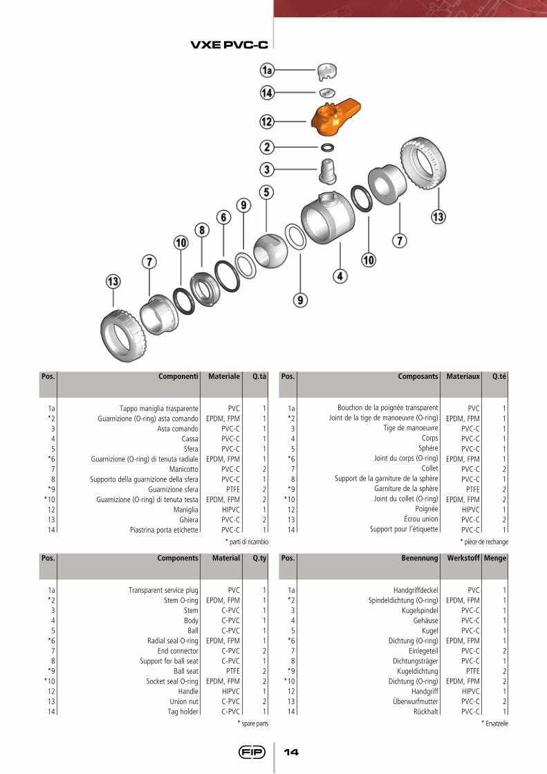
14
Q.té
1111112122121
Materiaux
PVCEPDM, FPM
PVC-CPVC-CPVC-C
EPDM, FPMPVC-CPVC-C
PTFEEPDM, FPM
HIPVCPVC-CPVC-C
Composants
Bouchon de la poignée transparentJoint de la tige de manoeuvre (O-ring)
Tige de manoeuvreCorps
SphéreJoint du corps (O-ring)
ColletSupport de la garniture de la sphère
Garniture de la sphèreJoint du collet (O-ring)
Poignéeécrou union
Support pour l’étiquette
Q.tà
1111112122121
Materiale
PVCEPDM, FPM
PVC-CPVC-CPVC-C
EPDM, FPMPVC-CPVC-C
PTFEEPDM, FPM
HIPVCPVC-CPVC-C
Pos.
1a*2345
*678
*9*10
121314
Componenti
Tappo maniglia trasparenteGuarnizione (O-ring) asta comando
Asta comandoCassaSfera
Guarnizione (O-ring) di tenuta radialeManicotto
Supporto della guarnizione della sferaGuarnizione sfera
Guarnizione (O-ring) di tenuta testaManiglia
GhieraPiastrina porta etichette
Pos.
1a*2345
*678
*9*10121314
* parti di ricambio * pièce de rechange
Menge
1111112122121
Werkstoff
PVCEPDM, FPM
PVC-CPVC-CPVC-C
EPDM, FPMPVC-CPVC-C
PTFEEPDM, FPM
HIPVCPVC-CPVC-C
Pos.
1a*2345
*678
*9*10121314
Q.ty
1111112122121
Material
PVCEPDM, FPM
C-PVCC-PVCC-PVC
EPDM, FPMC-PVCC-PVC
PTFEEPDM, FPM
HIPVCC-PVCC-PVC
Pos.
1a*2345
*678
*9*10
121314
Benennung
HandgriffdeckelSpindeldichtung (O-ring)
KugelspindelGehäuse
KugelDichtung (O-ring)
EinlegeteilDichtungsträger
KugeldichtungDichtung (O-ring)
HandgriffÜberwurfmutter
Rückhalt
Components
Transparent service plugStem O-ring
StemBodyBall
Radial seal O-ringEnd connector
Support for ball seatBall seat
Socket seal O-ringHandle
Union nutTag holder
* spare parts * Ersatzeile
VXE PVC-C
15
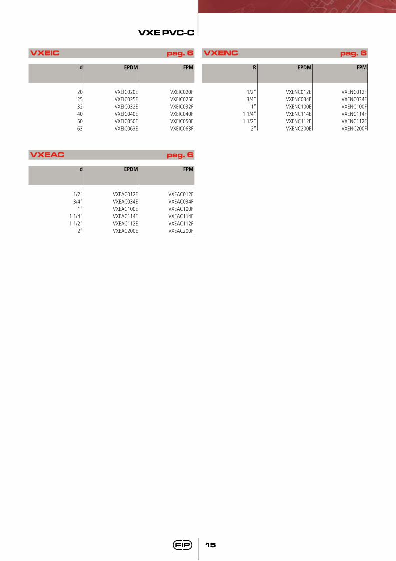
VXEAC pag. 6
d
1/2”3/4”
1”1 1/4”1 1/2”
2”
EPDM
VXEAC012EVXEAC034EVXEAC100EVXEAC114EVXEAC112EVXEAC200E
FPM
VXEAC012FVXEAC034FVXEAC100FVXEAC114FVXEAC112FVXEAC200F
VXEIC pag. 6
d
202532405063
EPDM
VXEIC020EVXEIC025EVXEIC032EVXEIC040EVXEIC050EVXEIC063E
FPM
VXEIC020FVXEIC025FVXEIC032FVXEIC040FVXEIC050FVXEIC063F
VXENC pag. 6
R
1/2”3/4”
1”1 1/4”1 1/2”
2”
EPDM
VXENC012EVXENC034EVXENC100EVXENC114EVXENC112EVXENC200E
FPM
VXENC012FVXENC034FVXENC100FVXENC114FVXENC112FVXENC200F
FIPFormatura
Iniezione Polimeri
Loc. Pian di Parata 16015 Casella Genova Italytel. +39 010 9621.1 fax +39 010 [email protected]
Since 1954 FIP produces injection moulded valves and fittings in thermoplastic materials for pressure pipeline systems thus becoming nowadays the la rges t European va lves manufacturer. F IP i s a company o f the Aliaxis Group: a worldwide industrial holding gathering together a series of companies manufacturing and marketing plastic plumbing products for building industrial and public utilities applications.FIP products are manufactured on EU production sites, operating to the Quality Assurance System in compliance with ISO 9001 and with the Environmental Management System ISO 14001 standards requirements. In FIP products there are over 50 years of know-how powered by a strong quest for innovation.
10
/20
09
Distributed by