TKD PVC-U - rohrleitungssysteme.de fileTKD PVC-U 56 l dati del presente prospetto sono forniti in...
25
Valvola a sfera a 3 vie DualBlock ® 3-way ball valve DualBlock ® Robinet à tournant sphérique à 3 voies DualBlock ® 3-Wege-Kugelhahn DualBlock ® TKD PVC-U
Transcript of TKD PVC-U - rohrleitungssysteme.de fileTKD PVC-U 56 l dati del presente prospetto sono forniti in...
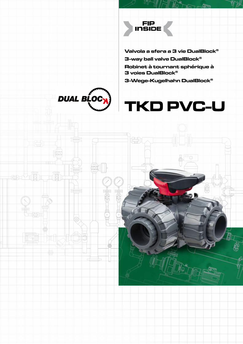
Valvola a sfera a 3 vie DualBlock®
3-way ball valve DualBlock®
Robinet à tournant sphérique à 3 voies DualBlock®
3-Wege-Kugelhahn DualBlock®
TKD PVC-U
TKD PVC-U
56
l dati del presente prospetto sono forniti in buona fede. La FIP non si assume alcuna responsabilità su quei dati non direttamente derivati da norme interna-zionali. La FIP si riserva di apportarvi qualsiasi modifica.
The data given in this leaflet are offered in good faith. No liability can be accepted concerning technical data that are not directly covered by recognized international Standards. FIP reserves the right to carry out any modification to the products shown in this leaflet.
Les données contenues dans cette brochure sont fournies en bonne foi. FIP n’assume aucune responsabilité pour les données qui ne dérivent pas directe-ment des normes internationales.FIP garde le droit d’apporter toute mo-dification aux produits présentés dans cette brochure.
Alle Daten dieser Druckschrift urden nach bestem Wissen angegeben, jedoch besteht keine Verbindlichkeit, sofern sie nicht direkt internationalen Normen entnommen wurden. Die Änderung von Maßen oder Ausführungen bleibt FIP vorbehalten.
TKD PVC-U
57
Valvola a sfera a 3 vie DualBlock®
3-way ball valve DualBlock®
Robinet à tournant sphérique à 3 voies DualBlock®
3-Wege-Kugelhahn DualBlock®
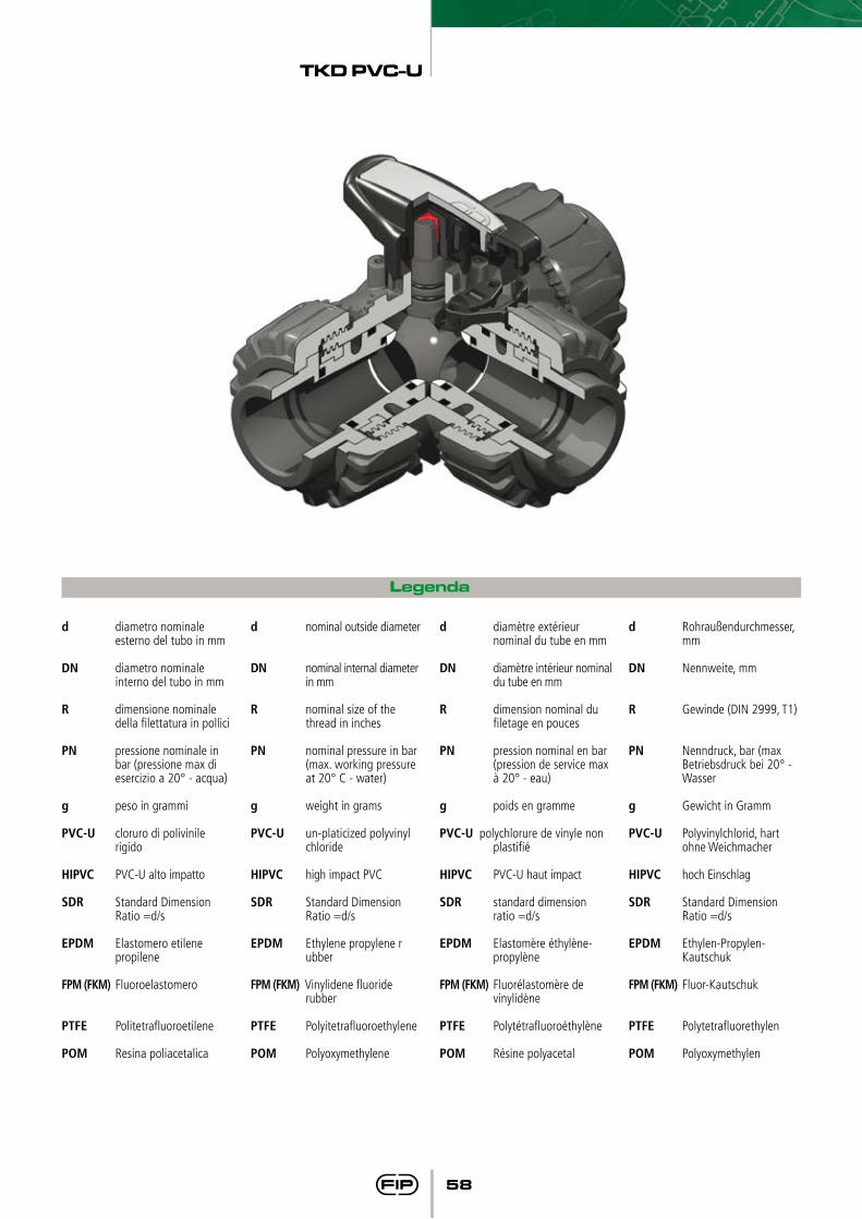
FIP ha sviluppato una valvola a sfera di tipo TK DualBlock® per introdurre un elevato standard di riferimento nella concezione delle valvole termo-plastiche. TKD è una valvola a sfera di smistamento e di miscelazione a smontaggio radiale, che risponde alla più severe esigenze richieste nelle applicazioni industriali.
• Gamma dimensionale da DN 10 a DN 50
• Pressioni di esercizio nominali fino a 16 bar a 20°C. Per il dettaglio vedere pagina seguente
• Sistema brevettato DualBlock®: il sistema di blocco assicura il serraggio delle ghiere anche nel caso di condizioni di
servizio gravose come, per esem-pio, in presenza di vibrazioni o dilatazioni termiche.
• Smontaggio radiale in tutti e tre gli attacchi
• Sfera a T (su richiesta a L)• Supporti sfera bloccati con possi-
bilità di smontaggio le tubazioni a valle con la valvola in posizione di chiusura.
• Sistema di tenuta Seat Stop® con possibilità di micro regolazione attraverso le ghiere e sistema di bloccaggio delle spinte assiali.
• Possibilità di bloccaggio della maniglia ogni 90° con sistema antimanomissione (opzionale)
• Possibilità di installare attuatori pneumatici e/o elettrici mediante l’utilizzo di appositi kit di montag-gio in PP-GR a foratura standard ISO 5211 F03-F04-F05- F07.
• Per maggiori informazioni visitare il sito: www.fipnet.it
FIP has developed a ball valve type TK DualBlock® to introduce an advanced standard of reference in thermoplastic valve design. TKD is a (true) union lock ball valve, used for diverting or mixing pipeline flows which stands up to the most severe industrial application requirements.
• Size range from DN 10 up to DN 50• Pressure rating: maximum wor-
king pressure 16 bar at 20°C. For details see following page
• Patented system DualBlock®: the locking device ensures the nuts are held in position even under severe service conditions: i.e. vibration or thermal expansion
• True union design : allows the easy removal of the valve body from the system at all three connection points
• T bore ball (L bore on request)• Safe blocked seats: possibility to
disconnect downstream pipes with the ball in closed position.
• Seat and seal design Seat Stop®: axial pipe loads blockand micro adjustment of ball seals.
• Handle stop device every 90° with safety block system (on request)
• Possibility to install electric or pneumatic actuators by means of
GR-PP mounting kits with stan-dard drilling (ISO 5211 F03- F04-F05-F07).
• For more information please visit our website: www.fipnet.it
FIP a développé un robinet à tournant sphèrique du type TK DualBlock® qui introduit un niveau très haut de référence dans la con-ception des robinets thermoplasti-ques. TKD est un robinet à sphère de prise d’échantillon, de dérivation et de mélange avec blocage de sécuri-té, qui peut satisfaire la pluspart des applications industrielles.
• La gamme dimensionnelle: de DN 10 jusqu’à DN 50
• Résistance à une pression de service jusqu’à 16 bar à 20°C. Voir page uivante pour les détails
• Système breveté DualBlock® : système de blocage qui assure la conservation de la position des écrous union, même en cas de dures conditions de service: par exemple avec des vibrations ou dilatation thermique.
• Démontage radial des trois raccords-unions
• Sphère avec alésage en T (ou L)• Démontage en charge: en position
fermée, le robinet permet le dé-montage de l’installation en aval par rapport à la direction du flux.
• Seat Stop® conception de sièges et point d’étanchéité qui permet un micro-ajustement par des embouts réglables et un système de blocage des poussées axiales.
• Poignée avec blocage de sécurité verrouillable tous les 90° (optio-nelle)
• Possibilité d’installer actionneurs electriques ou pneumatiques grâce à l’application de kit du montage en PP-GR (perçage ISO 5211 F03-F04-F05-F07).
• Pour toutes informations, visites le site: www.fipnet.it
FIP hat einen Kugelhahn, der Typ TK DualBlock® entwickelt, um einen hohen Standard in den thermoplasti-schen Ventilen einzuführen.TKD ist ein radial ein- und ausbau-barer, für Misch- oder Verteilfunktion geeigneter Kugelhahn, der den meisten industriellen Anwendungen gerecht wird. “Sicherheit und Zuverlässigkeit“ ist das Basisprinzip, das es zu erreichen galt.
• Abmessungen: von DN 10 bis DN 50
• Max Betriebsdruck: 16 bar bei 20°C. Für detaillierte Informatio-nen siehe die folgenden Seiten
• DualBlock® patentierte System: die Sperrvorrichtung hält dann die Überwurfmuttern unter verschie-densten Einsatzbedingungen (Vibrationen oder thermische Ausdehnung) sicher in Position.
• Radial lösbare Konstruktion: sie erlaubt den einfachen Ein-und Ausbau an allen 3 Anschlussenden
• T-Bohrung (L-Bohrung auf Anfrage)• In geschlossener Stellung des Ku-
gelhahns kann die drucklose Seite der Leitung gelöst werden
• SEAT-STOP Sitz- und Dichtungs-konzept: die Kugelabdichtung ist durch eine Mikro-Justierung frei von Rohrleitungskräften.
• Arretierungsmöglichkeit des Hebels (jede 90°) mit Sicherheits-schlosssystem (optional)
• Adapterflansch aus GR-PP, für eine einfache Montage von Handge-triebe oder elektrischen oder pneumatischen Antrieben mit den Anschlussmaßen F03- F04- 05- 07 nach ISO 5211.
• Für weitere Details schauen Sie auf unsere Website: www.fipnet.it
TKD PVC-U
58
Legenda
d diametro nominale esterno del tubo in mm
DN diametro nominale interno del tubo in mm
R dimensione nominale della filettatura in pollici
PN pressione nominale in bar (pressione max di esercizio a 20° - acqua)
g peso in grammi
PVC-U cloruro di polivinile rigido
HIPVC PVC-U alto impatto
SDR Standard Dimension Ratio =d/s
EPDM Elastomero etilene propilene
FPM (FKM) Fluoroelastomero
PTFE Politetrafluoroetilene
POM Resina poliacetalica
d nominal outside diameter
DN nominal internal diameter in mm
R nominal size of the thread in inches
PN nominal pressure in bar (max. working pressure
at 20° C - water)
g weight in grams
PVC-U un-platicized polyvinyl chloride
HIPVC high impact PVC
SDR Standard Dimension Ratio =d/s
EPDM Ethylene propylene r ubber
FPM (FKM) Vinylidene fluoride rubber
PTFE Polyitetrafluoroethylene
POM Polyoxymethylene
d diamètre extérieur nominal du tube en mm
DN diamètre intérieur nominal du tube en mm
R dimension nominal du filetage en pouces
PN pression nominal en bar (pression de service max à 20° - eau)
g poids en gramme
PVC-U polychlorure de vinyle non plastifié
HIPVC PVC-U haut impact
SDR standard dimension ratio =d/s
EPDM Elastomère éthylène- propylène
FPM (FKM) Fluorélastomère de vinylidène
PTFE Polytétrafluoroéthylène
POM Résine polyacetal
d Rohraußendurchmesser, mm
DN Nennweite, mm
R Gewinde (DIN 2999, T1)
PN Nenndruck, bar (max Betriebsdruck bei 20° - Wasser
g Gewicht in Gramm
PVC-U Polyvinylchlorid, hart ohne Weichmacher
HIPVC hoch Einschlag
SDR Standard Dimension Ratio =d/s
EPDM Ethylen-Propylen- Kautschuk
FPM (FKM) Fluor-Kautschuk
PTFE Polytetrafluorethylen
POM Polyoxymethylen
TKD PVC-U
59
Nm
25
20
15
10
5
0
DN2015 25 504032
Dati Tecnici
Technical Data
Données Techniques
Technische Daten
1
mom
ento
di m
anov
ra -
torq
ue -
coup
le
de m
anoe
uvre
- Be
tätig
ungs
mom
ente
2bar
16
14
12
10
8
6
4
2
0
-20 0 2 0 4 0 ° C 60 100 80
pres
sione
di e
serc
izio
- wor
king
pre
ssur
epr
essio
n de
ser
vice
- Be
trieb
sdru
ck
temperatura di esercizio - working temperaturetempérature de service - Betriebstemperatur
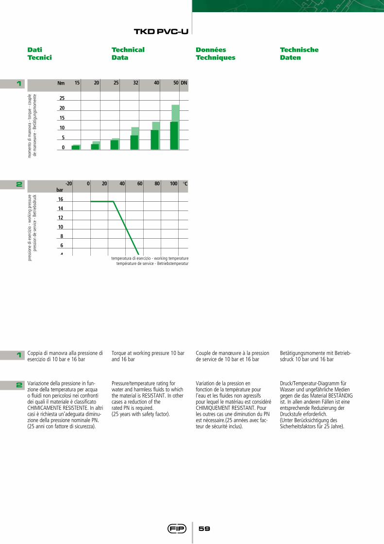
1 Coppia di manovra alla pressione di esercizio di 10 bar e 16 bar
Torque at working pressure 10 bar and 16 bar
Couple de manœuvre à la pression de service de 10 bar et 16 bar
Betätigungsmomente mit Betrieb-sdruck 10 bar und 16 bar
2 Variazione della pressione in fun-zione della temperatura per acqua o fluidi non pericolosi nei confronti dei quali il materiale è classificato CHIMICAMENTE RESISTENTE. In altri casi è richiesta un’adeguata diminu-zione della pressione nominale PN. (25 anni con fattore di sicurezza).
Pressure/temperature rating forwater and harmless fluids to which the material is RESISTANT. In other cases a reduction of therated PN is required.(25 years with safety factor).
Variation de la pression enfonction de la température pourl’eau et les fluides non agressifspour lequel le matériau est considéré CHIMIQUEMENT RESISTANT. Pour les outres cas une diminution du PN est nécessaire.(25 années avec fac-teur de sécurité inclus).
Druck/Temperatur-Diagramm fürWasser und ungefährliche Mediengegen die das Material BESTÄNDIG ist. In allen anderen Fällen ist eineentsprechende Reduzierung derDruckstufe erforderlich.(Unter Berücksichtigung des Sicherheitsfaktors für 25 Jahre).
TKD PVC-U
60
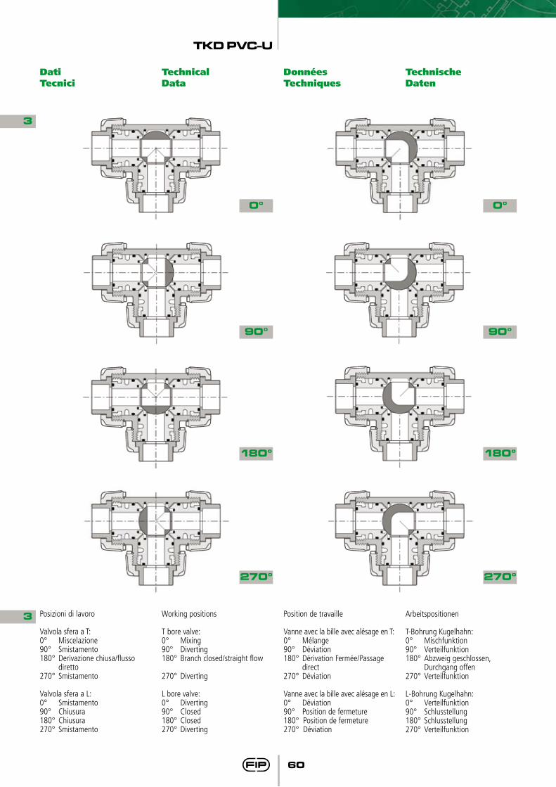
3
3 Posizioni di lavoro
Valvola sfera a T:0° Miscelazione90° Smistamento 180° Derivazione chiusa/flusso diretto 270° Smistamento
Valvola sfera a L:0° Smistamento90° Chiusura 180° Chiusura270° Smistamento
Working positions
T bore valve:0° Mixing90° Diverting 180° Branch closed/straight flow
270° Diverting
L bore valve:0° Diverting90° Closed 180° Closed 270° Diverting
Position de travaille
Vanne avec la bille avec alésage en T:0° Mélange90° Déviation180° Dérivation Fermée/Passage direct 270° Déviation
Vanne avec la bille avec alésage en L:0° Déviation90° Position de fermeture 180° Position de fermeture 270° Déviation
Arbeitspositionen
T-Bohrung Kugelhahn:0° Mischfunktion90° Verteilfunktion 180° Abzweig geschlossen, Durchgang offen270° Verteilfunktion
L-Bohrung Kugelhahn:0° Verteilfunktion90° Schlusstellung 180° Schlusstellung270° Verteilfunktion
0° 0°
90° 90°
180° 180°
270° 270°
Dati Tecnici
Technical Data
Données Techniques
Technische Daten
TKD PVC-U
61
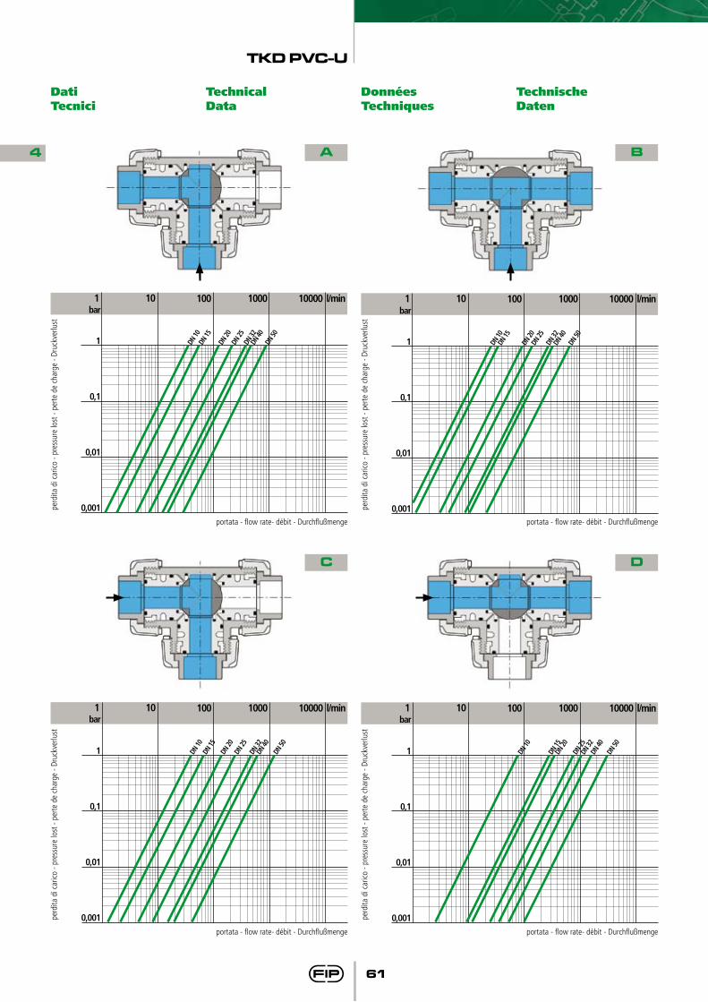
bar
1
0,1
0,01
0,001
DN 10
DN
15
DN 20
DN
25
DN 32
100 l/min 1000 10000 10 1
DN 40
DN
50
B
Dati Tecnici
Technical Data
Données Techniques
Technische Daten
4
perd
ita d
i car
ico -
pres
sure
lost
- pe
rte d
e ch
arge
- Dr
uckv
erlu
st
A
portata - flow rate- débit - Durchflußmenge
bar
1
0,1
0,01
0,001
DN 10
DN
15
DN 20
DN
25
DN 32
100 l/min 1000 10000 10 1
DN 40
DN
50
perd
ita d
i car
ico -
pres
sure
lost
- pe
rte d
e ch
arge
- Dr
uckv
erlu
st
B
portata - flow rate- débit - Durchflußmenge
bar
1
0,1
0,01
0,001
DN 10
DN
15
DN 20
DN
25
DN 32
100 l/min 1000 10000 10 1
DN 40
DN
50
perd
ita d
i car
ico -
pres
sure
lost
- pe
rte d
e ch
arge
- Dr
uckv
erlu
st
C
portata - flow rate- débit - Durchflußmenge
bar
1
0,1
0,01
0,001
DN 10
DN 15
DN
20
DN 25
DN
32
100 l/min 1000 10000 10 1
DN 40
DN
50
perd
ita d
i car
ico -
pres
sure
lost
- pe
rte d
e ch
arge
- Dr
uckv
erlu
st
D
portata - flow rate- débit - Durchflußmenge
TKD PVC-U
62
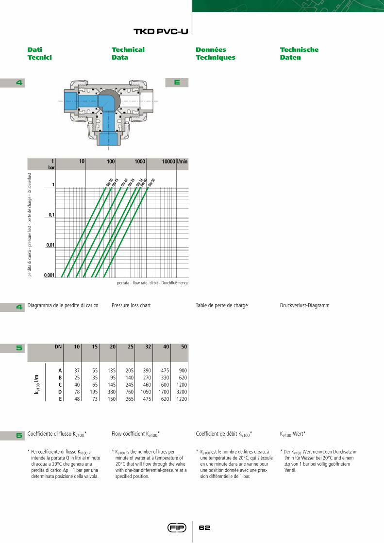
bar
1
0,1
0,01
0,001
DN 10
DN
15
DN 20
DN
25
DN 32
100 l/min 1000 10000 10 1
DN 40
DN
50
perd
ita d
i car
ico -
pres
sure
lost
- pe
rte d
e ch
arge
- Dr
uckv
erlu
st
E
portata - flow rate- débit - Durchflußmenge
Dati Tecnici
Technical Data
Données Techniques
Technische Daten
4
4 Diagramma delle perdite di carico Pressure loss chart Table de perte de charge Druckverlust-Diagramm
5
5 Coefficiente di flusso Kv100* Flow coefficient Kv100* Coefficient de débit Kv100* Kv100-Wert*
* Per coefficiente di flusso Kv100 si intende la portata Q in litri al minuto di acqua a 20°C che genera una perdita di carico ∆p= 1 bar per una determinata posizione della valvola.
* Kv100 is the number of litres per minute of water at a temperature of 20°C that will flow through the valve with one-bar differential-pressure at a specified position.
* Kv100 est le nombre de litres d’eau, à une température de 20°C, qui s’écoule en une minute dans une vanne pour une position donnée avec une pres-sion différentielle de 1 bar.
* Der Kv100-Wert nennt den Durchsatz in l/min für Wasser bei 20°C und einem ∆p von 1 bar bei völlig geöffnetem Ventil.
50
900620
120032001220
40
475330600
1700620
32
390270460
1050475
25
205140245760265
20
13595
145380150
15
553565
19573
10
3725407848
DN
ABCDE
k v10
0 l/m
TKD PVC-U
63
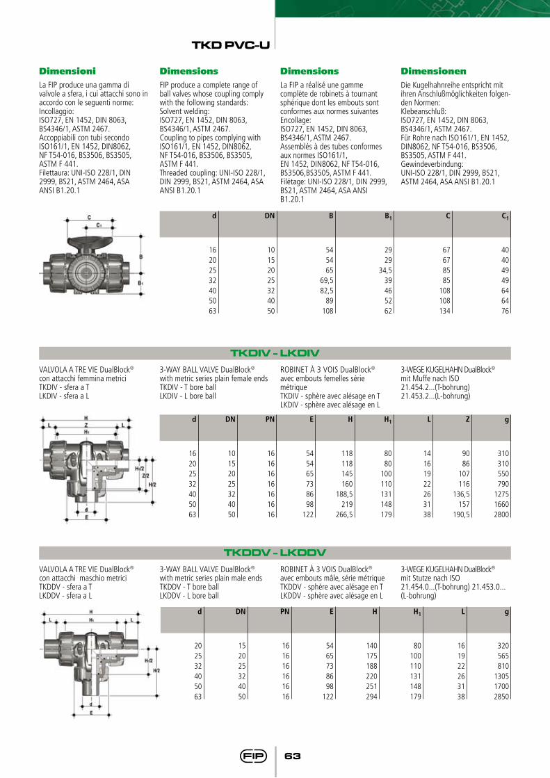
Dimensioni Dimensions Dimensions DimensionenLa FIP produce una gamma di valvole a sfera, i cui attacchi sono in accordo con le seguenti norme:Incollaggio:ISO727, EN 1452, DIN 8063, BS4346/1, ASTM 2467.Accoppiabili con tubi secondo ISO161/1, EN 1452, DIN8062, NF T54-016, BS3506, BS3505, ASTM F 441.Filettaura: UNI-ISO 228/1, DIN 2999, BS21, ASTM 2464, ASAANSI B1.20.1
FIP produce a complete range of ball valves whose coupling comply with the following standards:Solvent welding:ISO727, EN 1452, DIN 8063, BS4346/1, ASTM 2467.Coupling to pipes complying with ISO161/1, EN 1452, DIN8062, NF T54-016, BS3506, BS3505, ASTM F 441.Threaded coupling: UNI-ISO 228/1, DIN 2999, BS21, ASTM 2464, ASAANSI B1.20.1
La FIP a réalisé une gamme complète de robinets à tournant sphérique dont les embouts sont conformes aux normes suivantesEncollage:ISO727, EN 1452, DIN 8063, BS4346/1, ASTM 2467.Assemblés à des tubes conformes aux normes ISO161/1, EN 1452, DIN8062, NF T54-016, BS3506,BS3505, ASTM F 441.Filétage: UNI-ISO 228/1, DIN 2999, BS21, ASTM 2464, ASA ANSI B1.20.1
Die Kugelhahnreihe entspricht mit ihren Anschlußmöglichkeiten folgen-den Normen:Klebeanschluß:ISO727, EN 1452, DIN 8063, BS4346/1, ASTM 2467.Für Rohre nach ISO161/1, EN 1452, DIN8062, NF T54-016, BS3506, BS3505, ASTM F 441.Gewindeverbindung: UNI-ISO 228/1, DIN 2999, BS21, ASTM 2464, ASA ANSI B1.20.1
TKDIV - LKDIV VALVOLA A TRE VIE DualBlock® con attacchi femmina metriciTKDIV - sfera a TLKDIV - sfera a L
3-WAY BALL VALVE DualBlock® with metric series plain female endsTKDIV - T bore ballLKDIV - L bore ball
ROBINET À 3 VOIS DualBlock® avec embouts femelles série métriqueTKDIV - sphère avec alésage en TLKDIV - sphère avec alésage en L
3-WEGE KUGELHAHN DualBlock® mit Muffe nach ISO21.454.2...(T-bohrung) 21.453.2...(L-bohrung)
TKDDV - LKDDVVALVOLA A TRE VIE DualBlock® con attacchi maschio metriciTKDDV - sfera a TLKDDV - sfera a L
3-WAY BALL VALVE DualBlock® with metric series plain male endsTKDDV - T bore ballLKDDV - L bore ball
ROBINET À 3 VOIS DualBlock® avec embouts mâle, série métriqueTKDDV - sphère avec alésage en TLKDDV - sphère avec alésage en L
3-WEGE KUGELHAHN DualBlock® mit Stutze nach ISO21.454.0...(T-bohrung) 21.453.0...(L-bohrung)
C1
40404949646476
C
67678585
108108134
B1
2929
34,539465262
B
545465
69,582,5
89108
DN
10152025324050
d
16202532405063
g
310310550790
127516602800
Z
9086
107116
136,5157
190,5
L
14161922263138
H1
8080
100110131148179
H
118118145160
188,5219
266,5
E
545465738698
122
PN
16161616161616
DN
10152025324050
d
16202532405063
g
320565810
130517002850
L
161922263138
H1
80100110131148179
H
140175188220251294
E
5465738698
122
PN
161616161616
DN
152025324050
d
202532405063
TKD PVC-U
64
TKDLV - LKDLVVALVOLA A TRE VIE DualBlock® con attacchi femmina serie BSTKDLV - sfera a TLKDLV - sfera a L
3-WAY BALL VALVE DualBlock® with BS series plain female endsTKDLV - T bore ballLKDLV - L bore ball
ROBINET À 3 VOIS DualBlock® avec embouts femelles série BSTKDLV - sphère avec alésage en TLKDLV - sphère avec alésage en L
3-WEGE KUGELHAHN DualBlock® mit Muffe nach BSTKDLV - T - bohrungLKDLV - L - bohrung
g
310310550790
127516602800
Z
88,685
106,8115
136,6159
194,2
L
14,71719
22,526
30,236,2
H1
8080
100110131148179
H
118118
144,8160
188,6219,4266,6
E
545465738698
122
PN
16161616161616
DN
10152025324050
d
3/8”1/2”3/4”
1”1”1/41”1/2
2”
TKDFV - LKDFVVALVOLA A TRE VIE DualBlock® con attacchi femmina filettatura cilindrica gasTKDFV - sfera a TLKDFV - sfera a L
3-WAY BALL VALVE DualBlock® with BS parallel threaded female endsTKDFV - T bore ballLKDFV - L bore ball
ROBINET À 3 VOIS DualBlock® avec embouts femelles taraudés BSTKDFV - sphère avec alésage en TLKDFV - sphère avec alésage en L
3-WEGE KUGELHAHN DualBlock®mit Gewindemuffen nach BS21.454.1...(T-bohrung) 21.453.1...(L-bohrung)
g
310310550790
127516602800
Z
9595
114129151166199
L
11,415
16,319,121,421,425,7
H1
8080
100110131148179
H
118125146166
195,5211
253,5
E
545465738698
122
PN
16161616161616
DN
10152025324050
R
3/8”1/2”3/4”
1”1”1/41”1/2
2”
TKDAV - LKDAVVALVOLA A TRE VIE DualBlock® con attacchi femmina, serie ASTMTKDAV - sfera a TLKDAV - sfera a L
3-WAY BALL VALVE DualBlock® with ASTM series plain female endsTKDAV - T bore ballLKDAV - L bore ball
ROBINET À 3 VOIS DualBlock® avec embouts femelles, série ASTMTKDAV - sphère avec alésage en TLKDAV - sphère avec alésage en L
3-WEGE KUGELHAHN DualBlock® mit Muffe Nach ASTMTKDAV - T - bohrungLKDAV - L - bohrung
g
310310550790
127516602800
Z
93,287,2
108,2116,6
141157,6190,6
L
19,523
25,528,7
3235
38,2
H1
8080
100110131148179
E
545465738698
122
PN
16161616161616
DN
10152025324050
d
3/8”1/2”3/4”
1”1”1/41”1/2
2”
H
132,2132,2159,2
174205
227,6267
TKD PVC-U
65
TKDNV - LKDNVVALVOLA A TRE VIE DualBlock®
con attacchi femmina filettatura NPTTKDNV - sfera a TLKDNV - sfera a L
3-WAY BALL VALVE DualBlock® with NPT threaded female endsTKDNV - T bore ballLKDNV - L bore ball
ROBINET À 3 VOIS DualBlock® avec embouts femelles taraudé NPT TKDNV - sphère avec alésage en TLKDNV - sphère avec alésage en L
3-WEGE KUGELHAHN DualBlock® BLOCK mit Gewindemuffen nach NPTTKDNV - T - bohrungLKDNV - L - bohrung
g
310310550790
127516602800
L
13,71818
22,625,124,729,6
H1
8080
100110131148179
H
118126
146,4166,6195,8211,4253,8
E
545465738698
122
PN
16161616161616
DN
10152025324050
R
3/8”1/2”3/4”
1”1”1/41”1/2
2”
Z
90,690,4
110,4121,4145,6
162194,6
TKDJV - LKDJVVALVOLA A TRE VIE DualBlock® con attacchi femmina JISTKDJV - sfera a TLKDJV - sfera a L
3-WAY BALL VALVE DualBlock® with JIS series plain female endsTKDJV - T bore ballLKDJV - L bore ball
ROBINET À 3 VOIS DualBlock® avec embouts femelles série JISTKDJV - sphère avec alésage en TLKDJV - sphère avec alésage en L
3-WEGE KUGELHAHN DualBlock® mit Muffe nach JISTKDJV - T - bohrungLKDJV - L - bohrung
g
310550790
127516602800
Z
86107116137
157,2190
L
303540445563
H1
80100110131148179
H
146177196225
267,2316
E
5465738698
122
PN
161616161616
DN
152025324050
d
1/2”3/4”
1”1”1/41”1/2
2”
TKDGV - LKDGVVALVOLA A TRE VIE DualBlock® con attacchi femmina filettatura JISTKDGV - sfera a TLKDGV - sfera a L
3-WAY BALL VALVE DualBlock® with JIS threaded female endsTKDGV - T bore ballLKDGV - L bore ball
ROBINET À 3 VOIS DualBlock® avec embouts femelles taraudé JISTKDGV - sphère avec alésage en TLKDGV - sphère avec alésage en L
3-WEGE KUGELHAHN DualBlock® mit Gewindemuffen nach JISTKDGV - T - bohrungLKDGV - L - bohrung
g
310550790
127516602800
Z
86106,8
116138,6167,4204,6
L
161922252631
H1
80100110131148179
H
118144,8
160188,6219,4266,6
E
5465738698
122
PN
161616161616
DN
152025324050
R
1/2”3/4”
1”1”1/41”1/2
2”
TKD PVC-U
66
Accessori Accessories Accessoires Zubehör
CVDE
Codice/Part numberCode/Artikelnummer
CVDE11020CVDE11025CVDE11032CVDE11040CVDE11050CVDE11063
L
557074788491
DN
152025324050
d
202532405063
PSKD
H
190240258287316361
Prolunga stelo Stem extension Extension pour la tige Hebelverlängerung21.447.421
Codice/Part numberCode/Artikelnummer
PSKD020PSKD020PSKD025PSKD032PSKD040PSKD050PSKD063
DN
10152025324050
d
16202532405063
A1
25252525323232
A
32323232404040
A2
32324040505059
E
545465738698
122
B
707089
93,5110116122
B1
2929
34,539465262
Bmin
139,5139,5164,5
169200206225
CONNETTORI IN PE100 codolo lungo, per giunzioni con manicotti elettrici o testa a testa SDR 11
END CONNECTOR IN PE100 long spigot, for electrofusion or butt welding SDR 11
EMBOUTS MALES EN PE100 poursoudure par électrofusion oubout-à-bout SDR 11
ANSCHLUßTEILE MIT LANGEM STUTZEN AUS PE100 zum Stumpf und Elektromuffenschweissen SDR11034.447.312
TKD PVC-U
67
La valvola può essere fornita, a richiesta, completa di servocomandi. Esiste comunque la possibilità di installare attuatori pneumatici e/o elettrici mediante l’utilizzo diappositi kit di montaggio in PP-GR a foratura standard ISO 5211 F03-F04-F05.
The valve can be supplied with actuators on request.Possibility to install electric or pneu-matic actuators by means of GR-PP mounting kits with standard drilling (ISO 5211 F03- F04-F05-F07).
Sur demande, la vanne peut être fournie avec des servomoteurs.Possibilité d’installer actionneurs electriques ou pneumatiques grâce à l’application du kit de montage en PP-GR (perçage ISO 5211 F03-F04-F05-F07).
Auf Anfrage können die Armaturen komplett mit Antrieben geliefert werden.Adapterflansch aus GR-PP, für eine einfache Montage von Handgetrie-be oder elektrischen oder pneumati-schen Antrieben mit den Anschluss-maßen F03- F04- F05- F07 nach ISO 5211.
PowerQuick CP
Codice/Part numberCode/Artikelnummer
PQCP020PQCP020PQCP025PQCP032PQCP040PQCP050PQCP063
p x j
F03 x 5,5F03 x 5,5
*F03 x 5,5*F03 x 5,5F05 x 6,5F05 x 6,5F05 x 6,5
T
12121212161616
Q
11111111141414
B2
585869749197
114
DN
10152025324050
d
16202532405063
Modulo di attuazione per valvole pneumatiche
Actuation module for pneumatic valves
Module de montage pour action-neur pneumatique
Montagesatz für pneumatische Antriebe24.447.100
P x J
F04 x 5,5F04 x 5,5F05 x 6,5F05 x 6,5F07 x 8,5F07 x 8,5F07 x 8,5
*F04 x 5.5 on request
PowerQuick CE
Codice/Part numberCode/Artikelnummer
PQCE020PQCE020PQCE025PQCE032PQCE040PQCE050PQCE063
p x j
F03 x 5,5F03 x 5,5
*F03 x 5,5*F03 x 5,5F05 x 6,5F05 x 6,5F05 x 6,5
T
16161616161616
Q
14141414141414
B2
585869749197
114
DN
10152025324050
d
16202532405063
Modulo di attuazione per valvole elettriche
Actuation module for electric valves Module de montage pour action-neur électrique
Montagesatz für elektrische Antriebe24.447.500
P x J
F04 x 5,5F04 x 5,5F05 x 6,5F05 x 6,5F07 x 8,5F07 x 8,5F07 x 8,5
*F04 x 5.5 on request
TKD PVC-U
68
SHKD
Codice/Part numberCode/Artikelnummer
SHKD020SHKD032SHKD050SHKD063
DN
10 - 1520 - 2532 - 40
50
d
16 - 2025 - 3240 - 50
63
Kit blocco maniglia lucchettabile Handle block kit with padlock installation predisposal
Kit de blocage pour la poigné prédi-sposé pour le cadenassage
Arretierung des Handgriffes, abschließbar28.447.015
LTKD (90° - 180°)
Codice/Part number/Code/Artikelnummer
180°
LTKD180020LTKD180032LTKD180050LTKD180063
DN
10 - 1520 - 2532 - 40
50
d
16 - 2025 - 3240 - 50
63
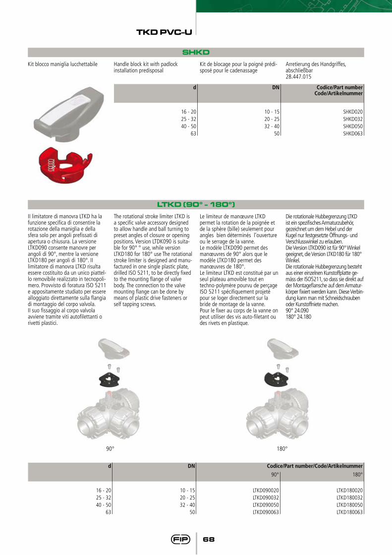
II limitatore di manovra LTKD ha la funzione specifica di consentire la rotazione della maniglia e della sfera solo per angoli prefissati di apertura o chiusura. La versione LTKD090 consente manovre per angoli di 90°, mentre la versione LTKD180 per angoli di 180°. II limitatore di manovra LTKD risulta essere costituito da un unico piattel-lo removibile realizzato in tecnopoli-mero. Provvisto di foratura ISO 5211 e appositamente studiato per essere alloggiato direttamente sulla flangia di montaggio del corpo valvola. II suo fissaggio al corpo valvola avviene tramite viti autofilettanti o rivetti plastici.
The rotational stroke limiter LTKD is a specific valve accessory designed to allow handle and ball turning to preset angles of closure or opening positions. Version LTDK090 is suita-ble for 90° ° use, while version LTKD180 for 180° use The rotational stroke limiter is designed and manu-factured in one single plastic plate, drilled ISO 5211, to be directly fixed to the mounting flange of valve body. The connection to the valve mounting flange can be done by means of plastic drive fasteners or self tapping screws.
Le limiteur de manœuvre LTKD permet la rotation de la poignée et de la sphère (bille) seulement pour angles bien déterminés l’ouverture ou le serrage de la vanne.Le modèle LTKD090 permet des manœuvres de 90° alors que le modèle LTKD180 permet des manœuvres de 180°.Le limiteur LTKD est constitué par un seul plateau amovible tout en techno-polymère pourvu de perçage ISO 5211 spécifiquement projeté pour se loger directement sur la bride de montage de la vanne.Pour le fixer au corps de la vanne on peut utiliser des vis auto-filetant ou des rivets en plastique.
Die rotationale Hubbegrenzung LTKD ist ein spezifisches Armaturzubehör, gezeichnet um dem Hebel und der Kugel nur festgesetzte Öffnungs- und Verschlusswinkel zu erlauben.Die Version LTKD090 ist für 90° Winkel geeignet, die Version LTKD180 für 180° Winkel.Die rotationale Hubbegrenzung besteht aus einer einzelnen Kunstoffplatte ge-mäss der ISO5211, so dass sie direkt auf der Montageflansche auf dem Armatur-körper fixiert werden kann. Diese Verbin-dung kann man mit Schneidschrauben oder Kunstoffniete machen.90° 24.090180° 24.180
90°
LTKD090020LTKD090032LTKD090050LTKD090063
90° 180°
TKD PVC-U
69
MSKD
C1
134134134134167167167
B1
2929
34,539465262
B
132,5132,5143,5148,5165,5171,5188,5
A1
858596
101118124141
A
5858
70,574
116122139
DN
10152025324050
d
16202532405063
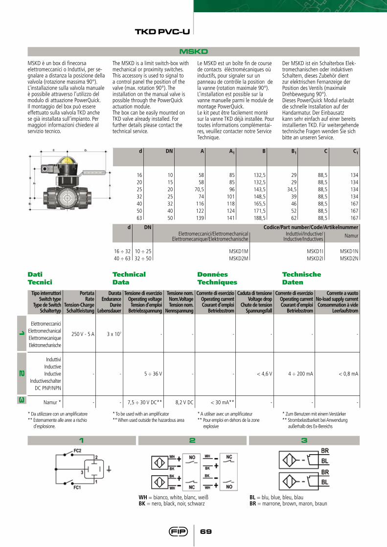
MSKD è un box di finecorsa elettromeccanici o Induttivi, per se-gnalare a distanza la posizione della valvola (rotazione massima 90°). L’installazione sulla valvola manuale è possibile attraverso l’utilizzo del modulo di attuazione PowerQuick.Il montaggio del box può essere effettuato sulla valvola TKD anche se già installata sull’impianto. Per maggiori informazioni chiedere al servizio tecnico.
The MSKD is a limit switch-box with mechanical or proximity switches. This accessory is used to signal to a control panel the position of the valve (max. rotation 90°). The installation on the manual valve is possible through the PowerQuick actuation module.The box can be easily mounted on TKD valve already installed. For further details please contact the technical service.
Le MSKD est un boîte fin de course de contacts éléctromécaniques où inductifs, pour signaler sur un panneau de contrôle la position de la vanne (rotation maximale 90°). L’installation est possible sur la vanne manuelle parmi le module de montage PowerQuick.Le kit peut être facilement monté sur la vanne TKD déjà installée. Pour toutes informations complémentai-res, veuillez contacter notre Service Technique.
Der MSKD ist ein Schalterbox Elek-tromechanischen oder induktiven Schaltern, dieses Zubehör dient zur elektrischen Fernanzeige der Position des Ventils (maximale Drehbewegung 90°). Dieses PowerQuick Modul erlaubt die schnelle Installation auf der Handarmatur. Der Einbausatz kann sehr einfach auf einer bereits installierten TKD. Für weitergehende technische Fragen wenden Sie sich bitte an unseren Service.
C
88,588,588,588,588,588,588,5
Codice/Part number/Code/Artikelnummer
Namur
MSKD1NMSKD2N
DN
10 ÷ 2532 ÷ 50
d
16 ÷ 3240 ÷ 63
Induttivi/Inductive/Inductive/Inductives
MSKD1IMSKD2I
Elettromeccanici/ElettromechanicalElettromecanique/Elektromechanische
MSKD1MMSKD2M
Dati Tecnici
Technical Data
Données Techniques
Technische Daten
WH = bianco, white, blanc, weißBK = nero, black, noir, schwarz
Corrente a vuotoNo-load supply currentConsommation à vide
Leerlaufstrom
-
< 0,8 mA
-
Caduta di tensioneVoltage drop
Chute de tensionSpannungsfall
-
< 4,6 V
-
Corrente di esercizioOperating currentCourant d’emploi
Betriebsstrom
-
-
< 30 mA**
Tensione nom.Nom.VoltageTension nom.
Nennspannung
-
-
8,2 V DC
Tensione di esercizioOperating voltageTension d’emploi
Betriebsspannung
-
5 ÷ 36 V
7,5 ÷ 30 V DC**
DurataEndurance
DuréeLebensdauer
3 x 10⁷
-
-
PortataRate
Tension-ChargeSchaltleistung
250 V - 5 A
-
-
Corrente di esercizioOperating currentCourant d’emploi
Betriebsstrom
-
4 ÷ 200 mA
-
Tipo interruttoriSwitch type
Type de SwitchSchaltertyp
ElettromeccaniciElettromechanicalElettromecaniqueElektromechanische
InduttiviInductiveInductive
InductiveschalterDC PNP/NPN
Namur *
1 2 3
12
3
* Da utilizzare con un amplificatore** Esternamente alle aree a rischio
d’esplosione.
* To be used with an amplificator** When used outside the hazardous area
* A utiliser avec un amplificateur** Pour emploi en dehors de la zone
explosive
* Zum Benutzen mit einem Verstärker** Strombelastbarkeit bei Anwendung
außerhalb des Ex-Bereichs
BL = blu, blue, bleu, blauBR = marrone, brown, maron, braun
TKD PVC-U
70
Staffaggio e supportazione
Valve bracketing and supporting
Fixation et supportage
Kugelhahn-Halterung und Befestigung
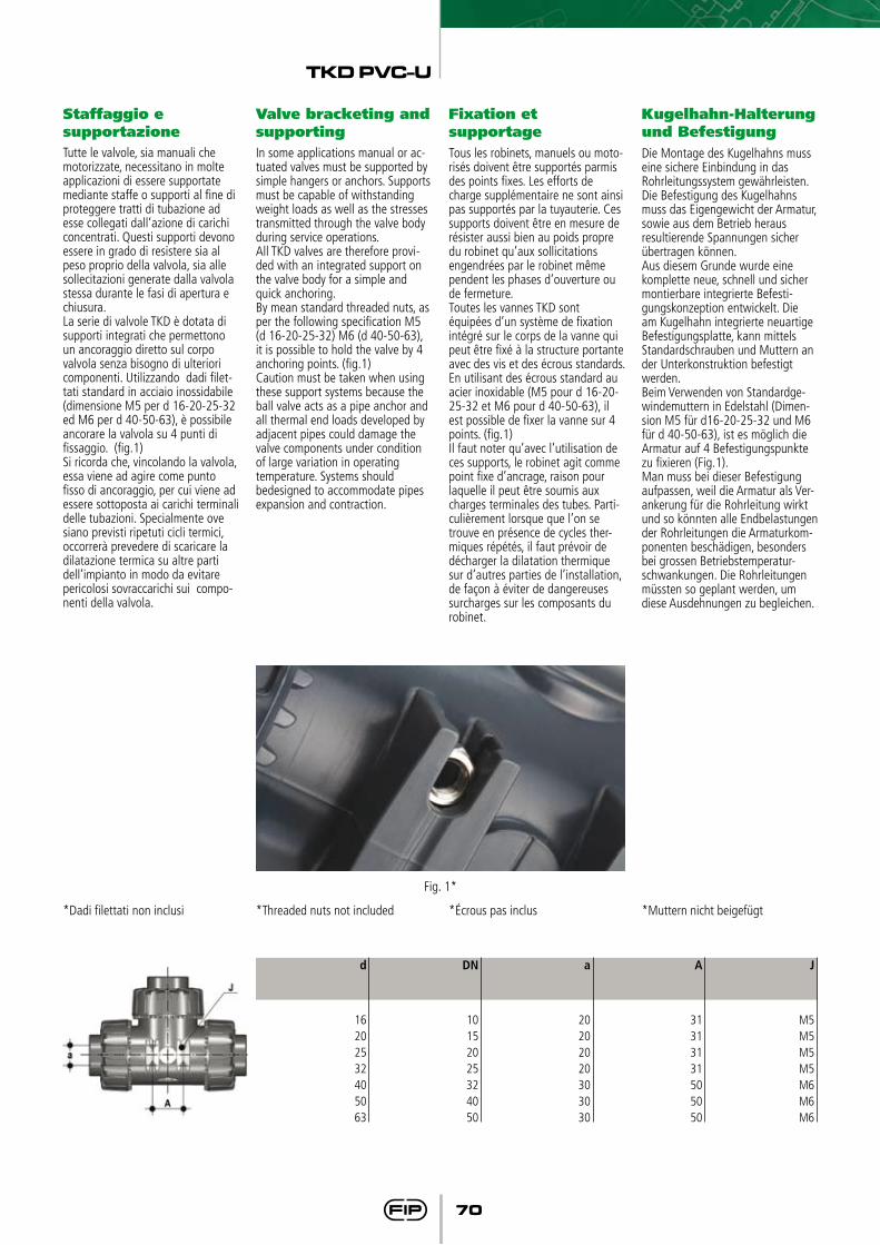
Tutte le valvole, sia manuali che motorizzate, necessitano in molte applicazioni di essere supportate mediante staffe o supporti al fine di proteggere tratti di tubazione ad esse collegati dall’azione di carichi concentrati. Questi supporti devono essere in grado di resistere sia al peso proprio della valvola, sia alle sollecitazioni generate dalla valvola stessa durante le fasi di apertura e chiusura. La serie di valvole TKD è dotata di supporti integrati che permettono un ancoraggio diretto sul corpo valvola senza bisogno di ulteriori componenti. Utilizzando dadi filet-tati standard in acciaio inossidabile (dimensione M5 per d 16-20-25-32 ed M6 per d 40-50-63), è possibile ancorare la valvola su 4 punti di fissaggio. (fig.1)Si ricorda che, vincolando la valvola, essa viene ad agire come punto fisso di ancoraggio, per cui viene ad essere sottoposta ai carichi terminali delle tubazioni. Specialmente ove siano previsti ripetuti cicli termici, occorrerà prevedere di scaricare la dilatazione termica su altre parti dell’impianto in modo da evitare pericolosi sovraccarichi sui compo-nenti della valvola.
In some applications manual or ac-tuated valves must be supported by simple hangers or anchors. Supports must be capable of withstanding weight loads as well as the stresses transmitted through the valve body during service operations.All TKD valves are therefore provi-ded with an integrated support on the valve body for a simple and quick anchoring.By mean standard threaded nuts, as per the following specification M5 (d 16-20-25-32) M6 (d 40-50-63), it is possible to hold the valve by 4 anchoring points. (fig.1)Caution must be taken when using these support systems because the ball valve acts as a pipe anchor and all thermal end loads developed by adjacent pipes could damage the valve components under condition of large variation in operating temperature. Systems should bedesigned to accommodate pipes expansion and contraction.
Tous les robinets, manuels ou moto-risés doivent être supportés parmis des points fixes. Les efforts de charge supplémentaire ne sont ainsi pas supportés par la tuyauterie. Ces supports doivent être en mesure de résister aussi bien au poids propre du robinet qu’aux sollicitations engendrées par le robinet même pendent les phases d’ouverture ou de fermeture.Toutes les vannes TKD sont équipées d’un système de fixation intégré sur le corps de la vanne qui peut être fixé à la structure portante avec des vis et des écrous standards. En utilisant des écrous standard au acier inoxidable (M5 pour d 16-20-25-32 et M6 pour d 40-50-63), il est possible de fixer la vanne sur 4 points. (fig.1)Il faut noter qu’avec l’utilisation de ces supports, le robinet agit comme point fixe d’ancrage, raison pour laquelle il peut être soumis aux charges terminales des tubes. Parti-culièrement lorsque que l’on se trouve en présence de cycles ther-miques répétés, il faut prévoir de décharger la dilatation thermique sur d’autres parties de l’installation, de façon à éviter de dangereuses surcharges sur les composants du robinet.
Die Montage des Kugelhahns muss eine sichere Einbindung in das Rohrleitungssystem gewährleisten.Die Befestigung des Kugelhahns muss das Eigengewicht der Armatur, sowie aus dem Betrieb heraus resultierende Spannungen sicher übertragen können.Aus diesem Grunde wurde eine komplette neue, schnell und sicher montierbare integrierte Befesti-gungskonzeption entwickelt. Die am Kugelhahn integrierte neuartige Befestigungsplatte, kann mittels Standardschrauben und Muttern an der Unterkonstruktion befestigt werden.Beim Verwenden von Standardge-windemuttern in Edelstahl (Dimen-sion M5 für d16-20-25-32 und M6 für d 40-50-63), ist es möglich die Armatur auf 4 Befestigungspunkte zu fixieren (Fig.1).Man muss bei dieser Befestigung aufpassen, weil die Armatur als Ver-ankerung für die Rohrleitung wirkt und so könnten alle Endbelastungen der Rohrleitungen die Armaturkom-ponenten beschädigen, besonders bei grossen Betriebstemperatur-schwankungen. Die Rohrleitungen müssten so geplant werden, um diese Ausdehnungen zu begleichen.
J
M5M5M5M5M6M6M6
A
31313131505050
a
20202020303030
DN
10152025324050
d
16202532405063
*Dadi filettati non inclusi *Threaded nuts not included *écrous pas inclus *Muttern nicht beigefügt
Fig. 1*
TKD PVC-U
71
Installazione sull’impianto
Connection to the system
Montage sur l’installation
Einbau in eineLeitung
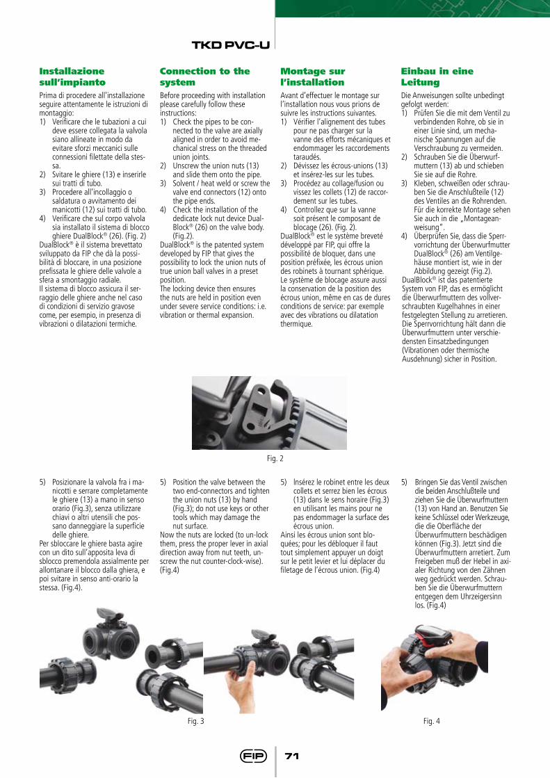
Prima di procedere all’installazione seguire attentamente le istruzioni di montaggio:1) Verificare che le tubazioni a cui deve essere collegata la valvola
siano allineate in modo da evitare sforzi meccanici sulle connessioni filettate della stes-sa.
2) Svitare le ghiere (13) e inserirle sui tratti di tubo.
3) Procedere all’incollaggio o saldatura o avvitamento dei manicotti (12) sui tratti di tubo.
4) Verificare che sul corpo valvola sia installato il sistema di blocco ghiere DualBlock® (26). (Fig. 2)
DualBlock® è il sistema brevettato sviluppato da FIP che dà la possi-bilità di bloccare, in una posizione prefissata le ghiere delle valvole a sfera a smontaggio radiale.Il sistema di blocco assicura il ser-raggio delle ghiere anche nel caso di condizioni di servizio gravose come, per esempio, in presenza di vibrazioni o dilatazioni termiche.
Before proceeding with installation please carefully follow these instructions:1) Check the pipes to be con-
nected to the valve are axially aligned in order to avoid me-chanical stress on the threaded union joints.
2) Unscrew the union nuts (13) and slide them onto the pipe.
3) Solvent / heat weld or screw the valve end connectors (12) onto the pipe ends.
4) Check the installation of the dedicate lock nut device Dual-Block® (26) on the valve body. (Fig.2).
DualBlock® is the patented system developed by FIP that gives the possibility to lock the union nuts of true union ball valves in a preset position. The locking device then ensures the nuts are held in position even under severe service conditions: i.e. vibration or thermal expansion.
Avant d’effectuer le montage sur l’installation nous vous prions de suivre les instructions suivantes.1) Vérifier l’alignement des tubes
pour ne pas charger sur la vanne des efforts mécaniques et endommager les raccordements taraudés.
2) Dévissez les écrous-unions (13) et insérez-les sur les tubes.
3) Procédez au collage/fusion ou vissez les collets (12) de raccor-dement sur les tubes.
4) Controllez que sur la vanne soit présent le composant de blocage (26). (Fig. 2).
DualBlock® est le système breveté développé par FIP, qui offre la possibilité de bloquer, dans une position préfixée, les écrous union des robinets à tournant sphérique.Le système de blocage assure aussi la conservation de la position des écrous union, même en cas de dures conditions de service: par exemple avec des vibrations ou dilatation thermique.
Die Anweisungen sollte unbedingt gefolgt werden:1) Prüfen Sie die mit dem Ventil zu
verbindenden Rohre, ob sie in einer Linie sind, um mecha-nische Spannungen auf die Verschraubung zu vermeiden.
2) Schrauben Sie die Überwurf-muttern (13) ab und schieben Sie sie auf die Rohre.
3) Kleben, schweißen oder schrau-ben Sie die Anschlußteile (12) des Ventiles an die Rohrenden. Für die korrekte Montage sehen Sie auch in die „Montagean-weisung“.
4) Überprüfen Sie, dass die Sperr-vorrichtung der Überwurfmutter DualBlock® (26) am Ventilge-häuse montiert ist, wie in der Abbildung gezeigt (Fig.2).
DualBlock® ist das patentierte System von FIP, das es ermöglicht die Überwurfmuttern des vollver-schraubten Kugelhahnes in einer festgelegten Stellung zu arretieren.Die Sperrvorrichtung hält dann die Überwurfmuttern unter verschie-densten Einsatzbedingungen (Vibrationen oder thermische Ausdehnung) sicher in Position.
5) Posizionare la valvola fra i ma-nicotti e serrare completamente le ghiere (13) a mano in senso orario (Fig.3), senza utilizzare chiavi o altri utensili che pos-sano danneggiare la superficie delle ghiere.
Per sbloccare le ghiere basta agire con un dito sull’apposita leva di sblocco premendola assialmente per allontanare il blocco dalla ghiera, e poi svitare in senso anti-orario la stessa. (Fig.4).
5) Position the valve between the two end-connectors and tighten the union nuts (13) by hand (Fig.3); do not use keys or other tools which may damage the nut surface.
Now the nuts are locked (to un-lock them, press the proper lever in axial direction away from nut teeth, un-screw the nut counter-clock-wise). (Fig.4)
5) lnsérez le robinet entre les deux collets et serrez bien les écrous (13) dans le sens horaire (Fig.3) en utilisant les mains pour ne pas endommager la surface des écrous union.
Ainsi les écrous union sont blo-quées; pour les débloquer il faut tout simplement appuyer un doigt sur le petit levier et lui déplacer du filetage de l’écrous union. (Fig.4)
5) Bringen Sie das Ventil zwischen die beiden Anschlußteile und ziehen Sie die Überwurfmuttern (13) von Hand an. Benutzen Sie keine Schlüssel oder Werkzeuge,
die die Oberfläche der Überwurfmuttern beschädigen können (Fig.3). Jetzt sind die Überwurfmuttern arretiert. Zum Freigeben muß der Hebel in axi-aler Richtung von den Zähnen weg gedrückt werden. Schrau-ben Sie die Überwurfmuttern entgegen dem Uhrzeigersinn los. (Fig.4)
Fig. 2
Fig. 4Fig. 3
TKD PVC-U
72
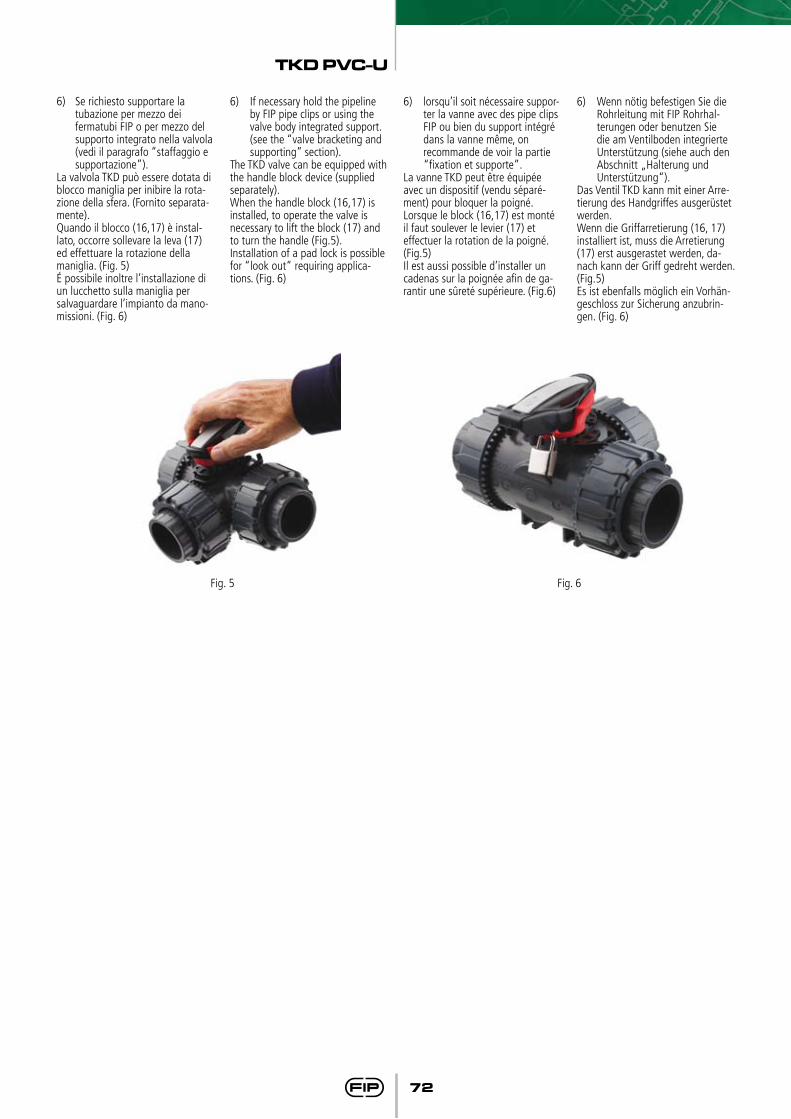
6) Se richiesto supportare la tubazione per mezzo dei fermatubi FIP o per mezzo del supporto integrato nella valvola (vedi il paragrafo “staffaggio e supportazione”).
La valvola TKD può essere dotata di blocco maniglia per inibire la rota-zione della sfera. (Fornito separata-mente).Quando il blocco (16,17) è instal-lato, occorre sollevare la leva (17) ed effettuare la rotazione della maniglia. (Fig. 5)é possibile inoltre l’installazione di un lucchetto sulla maniglia per salvaguardare l’impianto da mano-missioni. (Fig. 6)
6) If necessary hold the pipeline by FIP pipe clips or using the valve body integrated support. (see the “valve bracketing and supporting” section).
The TKD valve can be equipped with the handle block device (supplied separately).When the handle block (16,17) is installed, to operate the valve is necessary to lift the block (17) and to turn the handle (Fig.5). Installation of a pad lock is possible for “look out“ requiring applica-tions. (Fig. 6)
6) lorsqu’il soit nécessaire suppor-ter la vanne avec des pipe clips FIP ou bien du support intégré dans la vanne même, on
recommande de voir la partie “fixation et supporte”.
La vanne TKD peut être équipée avec un dispositif (vendu séparé-ment) pour bloquer la poigné.Lorsque le block (16,17) est monté il faut soulever le levier (17) et effectuer la rotation de la poigné. (Fig.5) Il est aussi possible d’installer un cadenas sur la poignée afin de ga-rantir une sûreté supérieure. (Fig.6)
6) Wenn nötig befestigen Sie die Rohrleitung mit FIP Rohrhal-terungen oder benutzen Sie die am Ventilboden integrierte Unterstützung (siehe auch den
Abschnitt „Halterung und Unterstützung“).
Das Ventil TKD kann mit einer Arre-tierung des Handgriffes ausgerüstet werden.Wenn die Griffarretierung (16, 17) installiert ist, muss die Arretierung (17) erst ausgerastet werden, da-nach kann der Griff gedreht werden. (Fig.5)Es ist ebenfalls möglich ein Vorhän-geschloss zur Sicherung anzubrin-gen. (Fig. 6)
Fig. 5 Fig. 6
TKD PVC-U
73
Regolazione delle tenute
Sealing adjusting Réglage de l’étanchéité
Justerierung der Dichtung
La regolazione delle tenute può es-sere effettuata utilizzando l’inserto estraibile sulla maniglia (Fig. 7).
The sealing adjustment can be un-dertaken using the removable insert on the handle (Fig. 7).
Le réglage de l’étanchéité peut être efféctué en utilisant l’outil inséré sur la poignée (Fig. 7).
Die Dichtungen können mit dem vom Hebel abnehmbaren Schlüssel-Einsatz justiert werden (Fig.7).
Dopo aver posizionato la sfera come in figura 8, usando tale inserto come attrezzo è possibile effettuare la regolazione delle tenute avvitan-do i supporti secondo la sequenza indicata (Fig.8).
After having positioned the ball as in the figure 8, the insert can be used as a tool to tighten the ball carrier to achieve the perfect sealing following the indicated sequence (Fig.8).
Après avoir orienté la bille comme indiqué sur la figure 8, les ergots de l’outil vous permettront d’effectuer un réglage fin de l’étanchéité en agissant sur la pièce (Fig.8).
Nachdem die Kugel wie in Fig.8 gestellt ist, kann man das Schlüssel-Einsatz um die Dichtungsträger nachzuziehen benutzten, gemäss der abgebildeten Reihenfolge. (Fig.8).
Una seconda regolazione delle tenute può essere effettuata con la valvola installata sulla tubazione sempli-cemente serrando ulteriormente le ghiere. Tale “micro-regolazione”, possibile solo con le valvole FIP grazie al siste-ma brevettato “Seat stop system”, permette di recuperare la tenuta, laddove vi fosse un consumo delle sedi sfera in PTFE dovuto all’usura per un elevato numero di manovre.
AvvertenzaEvitare sempre brusche manovre di chiusura e proteggere la valvola da manovre accidentali.
A secondary “micro-adjusting” can be carried out on the valve already installed on the pipeline just tighte-ning the external nut.Thanks to the FIP patented “Seat stop system” it is possible to achie-ve the sealing in spite of the PTFE seats wearing due to the heavy duty cycle.
WarningIt is important to avoid rapid closure of valves to eliminate the possibility of water hammer causing damage to the pipeline.
Un deuxième “micro-ajustement” peut être effectué lorsque la vanne est installée sur la canalisation en serrant simplement les écrous.Grâce à ce système breveté par FIP et appelé “Seat Stop System”, vous pourrez ainsi régler l’étanchéité des joints de siège en PTFE et garantir à votre vanne un nombre plus élevé de manœuvres.
AttentionIl est important d’éviter la fermeture trop rapide des vannes.
Des weiteren erlaubt dieses innovative Kugelhahnbauteil eine Nachjustierung (“Micro-adjust-ment“) der Dichtung (Verlängerung der Wartungsintervalle), ohne den Kugelhahn aus der Rohrleitung ausbauen zu müssen. Dies geschieht durch einfaches Nachziehen der Überwurfmuttern.
WarnungDas rasche Schließen von Armaturen ist zu vermeiden, diese müssen auch von zufälligen Schaltungen geschützt werden.
Fig. 7
Fig. 8
1
32
1
32
TKD PVC-U
74
Smontaggio Disassembly Démontage Demontage1) Isolare la valvola dal flusso.2) Sbloccare le ghiere premendo
sulla leva del DualBlock® (26) in direzione assiale allon-
tanandola dalla ghiera. Vedi punto 5 “Installazione sull’Im-pianto”. È comunque possibile rimuovere completamente il dispositivo di blocco dal corpo valvola.
3) Svitare completamente le ghiere (13) e sfilare la cassa (7).
4) Dopo aver portato la maniglia (2) nella posizione con le tre frecce rivolte verso le tre bocche (per la sfera ad L con le due frecce rivolte alla bocca a e b),
estrarre dalla maniglia (2) l’ap-posito inserto (1) ed infilare le due sporgenze nelle corrispon-denti aperture degli anelli di fermo (15), estraendo così i
supporti (11) ad essi solidali con una rotazione antioraria.
5) Estrarre la sfera (6) dalla bocca centrale avendo cura di non danneggiare la superficie di tenuta.
6) Rimuovere dai supporti (11) le guarnizioni in PTFE (5) e gli
Oring (8), (9), (10).7) Tirare la maniglia (2) verso
l’alto per estrarla dell’asta comando (4).
8) Premere sull’asta comando (4) verso l’interno della cassa fino ad estrarla.
9) Togliere la guarnizione di PTFE (5) con il relativo O-ring (8) dall’interno del corpo valvola.
10) Togliere le guarnizioni (3) del-l’asta comando (4) dalle sedi.
1) Isolate the valve from the line (release the pressure and empty the pipeline).
2) Unlock the union nuts pressing in the lever on the DUAL
BLOCK ® (26). See point 5 of “Connection to the system”. It is also possible to remove completely from the body the block device.
3) Unscrew the union nuts (13) and drop the valve body (7) out of the line.
4) Place the handle (2) so that the three arrows are aligned with the three valve ports (with the L-bore ball the two arrows must be aligned with the ports a and b). Remove the special insert (1) from the handle and push the two projecting ends into the corresponding recesses on the ball seat stop ring (15). Unscrew the ball carriers (11) together with the stop rings (15), rotating counter-clockwise.
5) Remove the ball (6) from the centre entry (taking care not to damage the sealing surfaces)
6) Remove the PTFE seats (5) and O-rings (8), (9), (10) from their supports (11)
7) Pull the handle (2) upwards to remove it from the valve stem (4)
8) Press the stem (4) to drop into the valve body
9) Remove the PTFE seat (5) and the O- ing (8) from the valve body
10) Remove the O-rings (3) from the stem grooves (4)
1) lsoler la vanne de la ligne du flux: (enlever la pression et vider les tubes)
2) Débloquer les écrous union appuyant sur le levier du Dual-Block® (26) dans la direction de l’axe tout en éloignant de l’écrou. Voir point 5 “montage sur l’installation”. Il est aussi possible enlever du tout le di-spositif de blocage.
3) Dévissez les écrous (13) et retirez le corps robinet à bille (7) radialement de la conduite.
4) Placez la poignée (2) de telle sorte que les flèches d’indica-tion correspondent aux sorties de la vanne (avec une bille en L, les deux flèches doivent êtres alignées sur les sorties a et b). Ôtez l’outil spécial (1) de la poignée (2). A l’aide des ergots de l’outil (1), dévissez la pièce filetée (15) dans le sens anti-horaire et retirez la pièce (11).
5) Tournez la bille (6) de sorte que la poignée soit perpendiculaire au sens de passage. La bille peut-être alors retirée du corps (faire attention à ne pas en-dommager les états de surface)
6) Enlevez les joints de sièges en PTFE (5) et les joints O-rings (8), (9) et (10) de leur support (11)
7) Enlevez la poignée (2) en tirant vers le haut.
8) Poussez la tige de manoeuvre (4) dans le corps (7) et la retirer.
9) Enlevez les joints de sièges (5) et les O-rings (8) du corps de la vanne.
10) Enlevez les O-rings (3) de la tige de manoeuvre (4)
1) Die Leitung ist an geeigneter Stelle Drucklos zu machen und zu entleeren.
2) Entsperren Sie die Überwurf-muttern durch Druck auf den DualBlock® (26).
Es ist auch möglich die Sperr-vorrichtung aus dem Kugelhahn Gehäuse komplett abzuziehen.
3) Lösen der Überwurfmuttern (13) und Entnahme des Kugelhahnskörpers (7) aus der Leitung.
4) Stellen Sie den Handgriff so, dass die 3 Pfeile mit den Kugel-hahnöffnungen übereinstimmen (beim 3-Wege- Kugelhahn mit L-Bohrung müssen die Öffnungen a) und b) geöffnet sein. Nach dem Lösen des Spe-zialeinsatzes (1) des Handgriffs kann dieses als Werkzeug zum Öffnen der 3 Dichtungsträger (11 und 15) verwendet werden.
5) Anschließend, kann die Kugel (6) ausgebaut werden.
6) Ebenso wie die PTFE Dichtun-gen (5) und die Oringe (8,9,10).
7) Zur kompletten Demontage ist jetzt der Handgriff nach oben abzuziehen.
8) Die Kugelspindel (4) in den Kugelkörper zu drücken.
9) Die PTFE-Dichtung (5) und der O-Ring (8) können vom Kugel-körper demontiert werden.
10) Die beiden O-Ringe (3) der Kugelspindel (4) demontieren
Montaggio Assembly Montage Montage1) Inserire le guarnizioni (3)
sull’asta comando2) Inserire nella sede presente
all’interno del corpo valvola l’O-ring (8), e successivamente la guarnizione di PTFE (5)
3) Inserire l’asta comando (4), dall’interno, nella cassa, avendo cura che le tre tacche poste sulla testa corrispondano alle tre uscite
4) Inserire la sfera (6) dalla bocca centrale b avendo cura che i tre
fori siano in corrispondenza con le tre uscite (per la sfera ad L i due fori dovranno essere in
corrispondenza con le bocche a e b)
5) Inserire gli O-ring (8), le guarni-zioni in PTFE (5) , gli O-ring di testa (10) e gli O-ring di tenuta radiale (9), nelle loro sedi sui supporti (11)
6) Inserire i tre supporti (11+15) avvitandoli in senso orario con l’apposito inserto (1) iniziando da quello sulla bocca centrale b
1) Position the stem O-rings (3) in their grooves
2) Insert the O-ring (8) and PTFE (5) in the body inside seat
3) Insert the stem (4) by pressing it upwards from inside the body
and ensure that the three moulded lines on the top of the stem coincide with the three valve ports
4) Slide the ball (6) into the valve body, with orifices coinciding to the valve ports (For L-bore ball let coincide the two orifices with the valve ports a and b)
5) Place the O-rings (8), the PTFE ball seats (5), the socket O-rings (10) and body O-rings (9) in their grooves in the ball carriers (11)
6) Starting with the centre one b, screw clockwise the three carriers (11+15) by the special insert tool (1)
1) Insérez les O-rings (3) sur la tige de manœuvre (4)
2) Insérez les O-ring (8) et les joints en PTFE (5) dans le corps (7)
3) Insérez la tige de manœuvre (4) par l’intérieur du corps en respectant les trois creins
4) Insérez la bille (6) en respectant le marquage des sorties (une bille en L doit être alignée sur les sorties a et b)
5) Placez les O-rings (8), les joints de sièges en PTFE (5), les joints du collets (10) et les joints du corps (9)
6) Vissez les pièces (11+15) avec l’outil (1) en commençant par le centre b
1) Die beiden O-Ringe (3) der Kugelspindel (4) montieren
2) Der O-Ring (8) und die PTFE-Dichtung (5) können in den Kugelkörper montiert werden
3) Die Kugelspindel (4) von der Innenseite des Gehäuses her einzusetzen. Die auf der Stimmseite der Spindel sicht-baren Linien müssen mit den Anschlüssen übereinstimmen
4) Die Kugel in die Öffnung b) einsetzen, die Öffnungen müs-sen offen sein (Für die L-Kugel müssen die Öffnungen a) und b) geöffnet sein)
5) Die PTFE-Dichtungen (5) und die O-Ringe (8,9,10) müssen auf die Kugelhahnträger mon-tiert werden
6) Die Kugelträger einsetzen (11+15), diese im Uhrzeigersinn nachziehen (starten mit b)
TKD PVC-U
75
8) Riporre l’inserto (1) sulla mani-glia (2)
9) Inserire i manicotti (12) e le ghiere avendo cura che gli O-ring di tenuta testa (10) non fuoriescano dalla loro sede sul supporto
10) Serrare le ghiere (13)
8) Place the special insert (1) on the handle (2)
9) Insert the end connectors (12) and the union nuts (13), taking care that the socket O-rings (10) do not come out of their grooves
10) Tighten the union nuts (13)
8) Replacez l’outil (1) dans la poignée (2).
9) Remettez en place les collets (12) et les écrous union (13) en vérifiant que les joints O-rings (10) soient bien en place.
10) Serrez à la main les unions (13).
8) Der Einsatz(1) in den Handgriff (2) wieder zu legen
9) Die Überwurfmuttern (12) und die Nutmuttern wieder einzusetzen, in dem man darauf achtet, dass die O-Ringe der Kopfdichtung (10) sich inner-halb Ihres Sitzes auf dem Halter befinden.
10) Die Nutmuttern zu spannen (13).
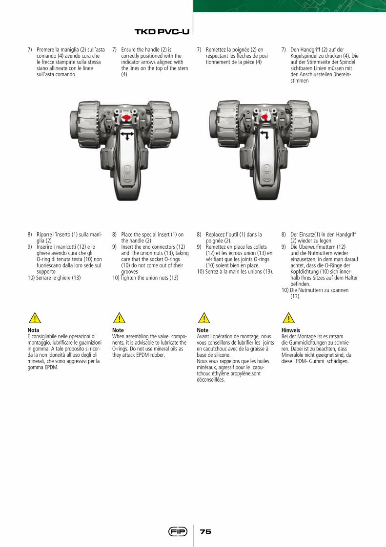
7) Premere la maniglia (2) sull’asta comando (4) avendo cura che le frecce stampate sulla stessa siano allineate con le linee sull’asta comando
7) Ensure the handle (2) is correctly positioned with the indicator arrows aligned with the lines on the top of the stem (4)
7) Remettez la poignée (2) en respectant les flèches de posi-tionnement de la pièce (4)
7) Den Handgriff (2) auf der Kugelspindel zu drücken (4). Die auf der Stimmseite der Spindel sichtbaren Linien müssen mit den Anschlussteilen überein-stimmen
Notaé consigliabile nelle operazioni di montaggio, lubrificare le guarnizioni in gomma. A tale proposito si ricor-da la non idoneità all’uso degli oli minerali, che sono aggressivi per la gomma EPDM.
NoteWhen assembling the valve compo-nents, it is advisable to lubricate the O-rings. Do not use mineral oils as they attack EPDM rubber.
NoteAvant l’opération de montage, nous vous conseillons de lubrifier les joints en caoutchouc avec de la graisse à base de silicone.Nous vous rappelons que les huiles minéraux, agressif pour le caou-tchouc éthylène propylène,sont déconseillées.
HinweisBei der Montage ist es ratsam die Gummidichtungen zu schmie-ren. Dabei ist zu beachten, dass Mineralöle nicht geeignet sind, da diese EPDM- Gummi schädigen.
TKD PVC-U
76
TKD PVC-U
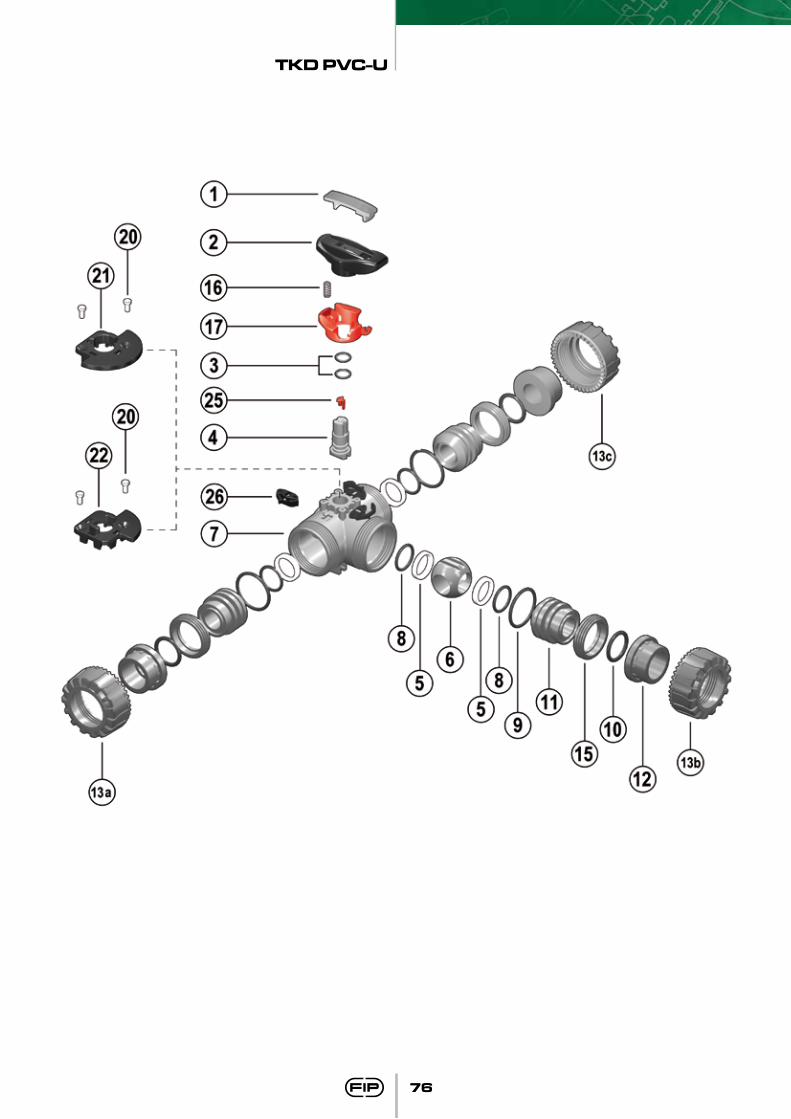
77
Q.té
112141143333331121113
Materiaux
PVC-UHIPVC
EPDM-FPMPVC-U
PTFEPVC-UPVC-U
EPDM-FPMEPDM-FPMEPDM-FPM
PVC-UPVC-UPVC-UPVC-U
acier inoxydablePP-GR
POMPOMPOMPOMPOM
Pos.
12
*34
*567
*89
*1011
*121315
**16**17**20**21**22
2526
Composants
Outil pour démontagePoignée
Joint de la tige de manoeuvreTige de manoeuvre
Garniture de la sphèreSphéreCorps
Joint du support de la garniture 5Joint du corps (O-ring)
Joint du colletSupport de la garniture de la sphère
Colletécrou union
Bague de fermetureRessort (SHKD)
Système de cadenassage pour la poignée (SHKD)Rivet pour LTKD
LTKD 180° LTKD 90°Indicateur
Dual Block®
Q.tà
112141143333331121113
Materiale
PVC-UHIPVC
EPDM-FPMPVC-U
PTFEPVC-UPVC-U
EPDM-FPMEPDM-FPMEPDM-FPM
PVC-UPVC-UPVC-UPVC-U
Acciaio inoxPP-GR
POMPOMPOMPOMPOM
Pos.
12
*34
*567
*89
*1011
*121315
**16**17**20**21**22
2526
Componenti
Inserto manigliaManiglia
Guarnizione asta comandoAsta comando
Guarnizione sferaSfera
CassaGuarnizione (O-ring) di supporto della guarnizione 5
Guarnizione (O-ring) di tenuta radialeGuarnizione (O-ring) di tenuta testa
Supporto della guarnizione della sferaManicotto
GhieraAnello di fermo
Molla (SHKD)Blocco di sicurezza per maniglia (SHKD)
Rivetto per LTKDLTKD 180°
LTKD 90°Indicatore di posizione
Dual Block®
Menge
112141143333331121113
Werkstoff
PVC-UHIPVC
EPDM-FPMPVC-U
PTFEPVC-UPVC-U
EPDM-FPMEPDM-FPMEPDM-FPM
PVC-UPVC-UPVC-UPVC-U
EdelstahlPP-GR
POMPOMPOMPOMPOM
Pos.
12
*34
*567
*89
*1011
*121315
**16**17**20**21**22
2526
Benennung
Schlüssel-EinsatzHandgriff
O-ringKugelspindelDichtungen
KugelGehäuse
O-Ring (zu Teil 5)O-RingO-Ring
DichtungsträgerAnschlußteile
ÜberwurfmutterGewinderingFeder (SHKD)
Sicherheitshandhebel mit Arretierung (SHKD)Niet für LTKD
LTKD 180° LYKD 90°
StellungsanzeigeDualBlock®
Q.ty
112141143333331121113
Material
PVC-UHIPVC
EPDM-FPMPVC-U
PTFEPVC-UPVC-U
EPDM-FPMEPDM-FPMEPDM-FPM
PVC-UPVC-UPVC-UPVC-U
Stainless steelPP-GR
POMPOMPOMPOMPOM
Pos.
12
*34
*567
*89
*1011
*121315
**16**17**20**21**22
2526
Components
InsertHandle
Stem O-ringStem
Ball seatBall
BodySupport O-ring for ball seat
Radial seal O-ringSocket seal O-ring
Support for ball seatEnd connector
Union nutStop ring
Spring (SHKD)Safety handle block (SHKD)
Drive fastener for LTKDLTKD 180°
LTKD 90°Position indicator
DualBlock®
* parti di ricambio ** accessori
* pièce de rechange ** accessoires
* spare parts ** accessories
* Ersatzeile ** Zubehör
Code
LKDAV pag. 64
d
3/8”1/2”3/4”
1”1 1/4”1 1/2”
2”
EPDM
LKDAV038ELKDAV012ELKDAV034ELKDAV100ELKDAV114ELKDAV112ELKDAV200E
FPM
LKDAV038FLKDAV012FLKDAV034FLKDAV100FLKDAV114FLKDAV112FLKDAV200F
LKDDV pag. 63
d
202532405063
EPDM
LKDDV020ELKDDV025ELKDDV032ELKDDV040ELKDDV050ELKDDV063E
FPM
LKDDV020FLKDDV025FLKDDV032FLKDDV040FLKDDV050FLKDDV063F
LKDFV pag. 64
R
3/8”1/2”3/4”
1”1 1/4”1 1/2”
2”
EPDM
LKDFV038ELKDFV012ELKDFV034ELKDFV100ELKDFV114ELKDFV112ELKDFV200E
FPM
LKDFV038FLKDFV012FLKDFV034FLKDFV100FLKDFV114FLKDFV112FLKDFV200F
LKDGV pag. 65
R
1/2”3/4”
1”1 1/4”1 1/2”
2”
EPDM
LKDGV012ELKDGV034ELKDGV100ELKDGV114ELKDGV112ELKDGV200E
FPM
LKDGV012FLKDGV034FLKDGV100FLKDGV114FLKDGV112FLKDGV200F
LKDIV pag. 63
d
16202532405063
EPDM
LKDIV016ELKDIV020ELKDIV025ELKDIV032ELKDIV040ELKDIV050ELKDIV063E
FPM
LKDIV016FLKDIV020FLKDIV025FLKDIV032FLKDIV040FLKDIV050FLKDIV063F
LKDJV pag. 65
d
1/2”3/4”
1”1 1/4”1 1/2”
2”
EPDM
LKDJV012ELKDJV034ELKDJV100ELKDJV114ELKDJV112ELKDJV200E
FPM
LKDJV012FLKDJV034FLKDJV100FLKDJV114FLKDJV112FLKDJV200F
LKDLV pag. 64
d
3/8”1/2”3/4”
1”1 1/4”1 1/2”
2”
EPDM
LKDLV038ELKDLV012ELKDLV034ELKDLV100ELKDLV114ELKDLV112ELKDLV200E
FPM
LKDLV038FLKDLV012FLKDLV034FLKDLV100FLKDLV114FLKDLV112FLKDLV200F
LKDNV pag. 65
R
3/8”1/2”3/4”
1”1 1/4”1 1/2”
2”
EPDM
LKDNV038ELKDNV012ELKDNV034ELKDNV100ELKDNV114ELKDNV112ELKDNV200E
FPM
LKDNV038FLKDNV012FLKDNV034FLKDNV100FLKDNV114FLKDNV112FLKDNV200F
TKDAV pag. 64
d
3/8”1/2”3/4”
1”1 1/4”1 1/2”
2”
EPDM
TKDAV038ETKDAV012ETKDAV034ETKDAV100ETKDAV114ETKDAV112ETKDAV200E
FPM
TKDAV038FTKDAV012FTKDAV034FTKDAV100FTKDAV114FTKDAV112FTKDAV200F
TKDDV pag. 63
d
202532405063
EPDM
TKDDV020ETKDDV025ETKDDV032ETKDDV040ETKDDV050ETKDDV063E
FPM
TKDDV020FTKDDV025FTKDDV032FTKDDV040FTKDDV050FTKDDV063F
Code
TKDIV pag. 63
d
16202532405063
EPDM
TKDIV016ETKDIV020ETKDIV025ETKDIV032ETKDIV040ETKDIV050ETKDIV063E
FPM
TKDIV016FTKDIV020FTKDIV025FTKDIV032FTKDIV040FTKDIV050FTKDIV063F
TKDGV pag. 65
R
1/2”3/4”
1”1 1/4”1 1/2”
2”
EPDM
TKDGV012ETKDGV034ETKDGV100ETKDGV114ETKDGV112ETKDGV200E
FPM
TKDGV012FTKDGV034FTKDGV100FTKDGV114FTKDGV112FTKDGV200F
TKDFV pag. 64
R
3/8”1/2”3/4”
1”1 1/4”1 1/2”
2”
EPDM
TKDFV038ETKDFV012ETKDFV034ETKDFV100ETKDFV114ETKDFV112ETKDFV200E
FPM
TKDFV038FTKDFV012FTKDFV034FTKDFV100FTKDFV114FTKDFV112FTKDFV200F
TKDJV pag. 65
d
1/2”3/4”
1”1 1/4”1 1/2”
2”
EPDM
TKDJV012ETKDJV034ETKDJV100ETKDJV114ETKDJV112ETKDJV200E
FPM
TKDJV012FTKDJV034FTKDJV100FTKDJV114FTKDJV112FTKDJV200F
TKDLV pag. 64
d
3/8”1/2”3/4”
1”1 1/4”1 1/2”
2”
EPDM
TKDLV038ETKDLV012ETKDLV034ETKDLV100ETKDLV114ETKDLV112ETKDLV200E
FPM
TKDLV038FTKDLV012FTKDLV034FTKDLV100FTKDLV114FTKDLV112FTKDLV200F
TKDNV pag. 65
R
3/8”1/2”3/4”
1”1 1/4”1 1/2”
2”
EPDM
TKDNV038ETKDNV012ETKDNV034ETKDNV100ETKDNV114ETKDNV112ETKDNV200E
FPM
TKDNV038FTKDNV012FTKDNV034FTKDNV100FTKDNV114FTKDNV112FTKDNV200F


![FINESTRE IN PVC E PVC-ALLUMINIO TOP 72 - Meuli Infissi · PDF fileLe finestre Finstral si contraddistinguono ... Trasmittanza termica Uf 1,2 W/m²K Tipologia vetro U g [W/m²K] UW](https://static.fdocumenti.com/doc/165x107/5a748e9b7f8b9a0d558bc77d/finestre-in-pvc-e-pvc-alluminio-top-72-meuli-infissi-a-le-finestre-finstral.jpg)