“UN CASO ESTREMO DI RINFORZO STRUTTURALE CON ... caso... · 7 m circa, da diaframmi trasversali...
13
RICERCA & RICERCA & RICERCA & RICERCA & SVILUPPO SVILUPPO SVILUPPO SVILUPPO INTEGRA “UN CASO ESTREMO DI RINFORZO STRUTTURALE CON PRECOMPRESSIONE ESTERNA: IL PONTE SUL GIBE IN ETIOPIA” Petrangeli M., Usai C., Zoppis E., Petrangeli M. (2008) “Questo articolo è stato pubblicato per la prima volta sulla rivista Industria Italiana del Cemento, casa editrice AITEC, http://www.aitecweb.com” “This article was first published in Industria Italiana del Cemento, publisher: AITEC, http://www.aitecweb.com” “Cet article a été publié pour la première fois sur Industria Italiana del Cemento, éditions: AITEC, http://www.aitecweb.com”http://www.pepublishing.com/” “Este artículo se publicó por primera vez en la revista Industria Italiana del Cemento, casa editorial : AITEC, http://www.aitecweb.com”http://www.pepublishing.com/”
Transcript of “UN CASO ESTREMO DI RINFORZO STRUTTURALE CON ... caso... · 7 m circa, da diaframmi trasversali...

RICERCA &RICERCA &RICERCA &RICERCA & SVILUPPOSVILUPPOSVILUPPOSVILUPPO
INTEGRA
“UN CASO ESTREMO DI RINFORZO STRUTTURALE CON PRECOMPRESSIONE ESTERNA: IL
PONTE SUL GIBE IN ETIOPIA”
Petrangeli M., Usai C., Zoppis E., Petrangeli M. (2008)
“Questo articolo è stato pubblicato per la prima volta sulla rivista Industria Italiana del Cemento, casa editrice
AITEC, http://www.aitecweb.com”
“This article was first published in Industria Italiana del Cemento, publisher: AITEC, http://www.aitecweb.com”
“Cet article a été publié pour la première fois sur Industria Italiana del Cemento, éditions: AITEC,
http://www.aitecweb.com”http://www.pepublishing.com/”
“Este artículo se publicó por primera vez en la revista Industria Italiana del Cemento, casa editorial : AITEC,
http://www.aitecweb.com”http://www.pepublishing.com/”

Introduction
The Gibe River bridge is located 185 km from Addis Abeba alongthe National Road connecting the capital to the city of Jima, the
largest city in the rich South-Western agricultural region of Ethiopia.The road was built by the Italians in the ’30. The crossing of the Giberiver was provided with a masonry arch bridge later sabotaged duringWorld War II and soon replaced with a steel truss girder simply sup-ported on the existing arch abutments.In the early ’80 the crossing was displaced few hundred metresupstream on a more direct alignment that required the construction ofa new concrete bridge (Fig. 1) made of 4 spans for a total length of120.5 m. Few years after its opening, during the civil war that preceded the fallof the military regime, the bridge was severely damaged by a bombthat severed a full section of the deck. The missing deck section was recast in situ in the early ’90 thusallowing the bridge to be re-opened to traffic. The bomb damages werenot fully repaired though, since the extensive cracking and spallingthat took place on the adjacent spans could not be tackled at that time.Those damages caused a progressive deterioration of the structureduring the subsequent years as the bridge is subjected to heavy trafficaround the clock. Recently, due to increased deck deterioration, load restrictions wereenforced diverting lorries and other heavy freight to the downstreamtruss girder.Unfortunately, this structure collapsed in November 2006 (Fig. 2)when a dozer carried by a low loader exceeding the maximum clear-ance crashed into the girder upper bracing causing the whole structu-re to collapse. The traffic had to be diverted back onto the concrete
808 iiC•12/2008
studi e tecnologiastudies & technology
Introduzione
Il Ponte sul fiume Gibe è ubicato a 185 km da Addis Abeba, lungol’arteria di interesse nazionale che collega la capitale a Jima, capo-
luogo della ricca regione agricola del Sud-Ovest. La strada e le relative strutture furono costruite dagli italiani, negli anni’30; l’attraversamento del fiume Gibe era garantito inizialmente da unponte ad arco in muratura che, sabotato dagli Inglesi durante la secon-da guerra mondiale, fu dagli stessi sostituito con una trave reticolare avia inferiore semplicemente poggiata sulle spalle del ponte preesisten-te. Nei primi anni ’80 l’attraversamento del Gibe venne spostato di alcunecentinaia di metri a monte su di un allineamento più diretto che richie-se la realizzazione di un nuovo ponte in cemento armato (Fig. 1) di 4campate per una lunghezza complessiva di 120.5m. Tale struttura fuperò gravemente danneggiata da una bomba durante la guerra civileche precedette la caduta della giunta militare provvisoria negli stessianni ’80. A seguito del bombardamento, la sezione del ponte crollata è stata rico-stituita permettendone nuovamente la transitabilità. I danni dellabomba si sono però ripercossi anche sulle altre campate, come spiega-to in maggior dettaglio nel seguito, e questi danni non sono stati ripara-ti portando nel tempo ad un progressivo deterioramento dell’impalcato.Il ponte ha continuato quindi ad essere utilizzato, anche se, negli ulti-mi anni, è stata posta una limitazione al carico transitabile; per i mezzipesanti si poteva comunque contare sulla trave reticolare posta a pochecentinaia di metri più a valle. Sfortunatamente questa struttura è crollata nel 2006 (Fig. 2) quando uncarico fuori sagoma ha impattato sui controventi superiori della travereticolare instabilizzandone i correnti principali. Tutto il traffico è statoquindi spostato nuovamente sul ponte in c.a. con le medesime limita-zioni di prima e carreggiata parzializzata. I mezzi articolati e i veicoli
Un caso estremo di rinforzo strutturale con precompressioneesterna: il ponte sul fiume Gibe in EtiopiaAn extreme case of structural reinforcing by external prestressing: the bridge over Gibe river in Ethiopia
• Fig. 1 - Il ponte in c.a. sul Gibe.• Fig. 1- The r.c. bridge over the Gibe river.
• Fig. 2 - La trave reticolare recentemente crollata.• Fig. 2- The trestlework beam that recently collapsed.
Tecnologia_12/08 26-11-2008 16:55 Pagina 808
809iiC•12/2008
studi e tecnologiastudies & technology
pesanti, diretti da Jima alla capitale e viceversa, sono stati costretti aduna lunghissima deviazione (150 km) via Nekempt, causando un gravedanno per l’economia della regione e del paese. Stante la situazione insostenibile, la Road Authority Etiope (ERA) hadisposto la realizzazione di un nuovo attraversamento che è già in fasedi costruzione qualche decina di metri a monte del ponte esistente. Lamessa in esercizio della nuova opera è prevista non prima di 2-3 anni.La situazione creatasi ha suggerito alla “Salini Costruttori S.p.A.”, dioffrire alle autorità un intervento rapido di riabilitazione del ponte inc.a. esistente. Questa operazione, condotta completamente a spese dellaSalini, aveva per altro un interesse strategico anche per la stessa impre-sa che è attualmente impegnata in 4 grandi progetti idroelettrici nelpaese, uno dei quali utilizza l’infrastruttura in oggetto per il trasporto dimateriali ed attrezzature. Il progetto di riparazione come descritto nelle pagine seguenti è statoquindi definito e presentato alle autorità a seguito del sopralluogo con-dotto dall’Ing. Eugenio Zoppis (responsabile tecnico della filiale Etiopedella Salini) e dal Prof. Marco Petrangeli, per conto della società diingegneria INTEGRA. I lavori, completati nel giro di 3 mesi, hannopermesso di riaprire al traffico il ponte senza alcuna limitazione di cari-co. Il costo complessivo dell’intervento, è stato pari a circa 400.000Euro.
La struttura del ponte
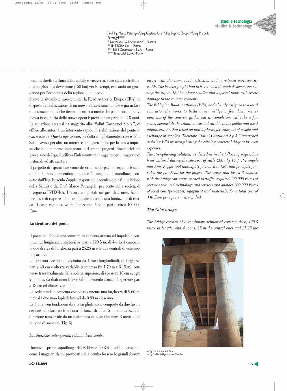
Il ponte sul Gibe è una struttura in cemento armato ad impalcato con-tinuo, di lunghezza complessiva pari a 120.5 m, diviso in 4 campate:le due di riva di lunghezza pari a 25.25 m e le due centrali di estensio-ne pari a 35 m.La struttura portante è costituita da 4 travi longitudinali, di larghezzapari a 40 cm e altezza variabile (compresa fra 1.70 m e 3.15 m), con-nesse trasversalmente dalla soletta superiore, di spessore 18 cm e, ogni7 m circa, da diaframmi trasversali in cemento armato di spessore paria 18 cm ed altezza variabile. La sede stradale presenta complessivamente una larghezza di 9.60 m,inclusi i due marciapiedi laterali da 0.80 m ciascuno.Le 3 pile, con fondazioni dirette su plinti, sono composte da due fusti asezione circolare posti ad una distanza di circa 5 m, solidarizzati indirezione trasversale da un diaframma di base alto circa 3 metri e dalpulvino di sommità (Fig. 3).
La situazione ante-operam: i danni della bomba
Durante il primo sopralluogo del Febbraio 2007si è subito constatatocome i maggiori danni provocati dalla bomba fossero le grandi fessure
girder with the same load restriction and a reduced carriagewaywidth. The heavier freight had to be rerouted through Nekempt increa-sing the trip by 150 km along smaller and unpaved roads with severedamage to the country economy.The Ethiopian Roads Authority (ERA) had already assigned to a localcontractor the works to build a new bridge a few dozen metresupstream of the concrete girder, but its completion will take a fewyears; meanwhile the situation was unbearable to the public and localadministration that relied on that highway for transport of people andexchange of supplies. Therefore “Salini Costruttori S.p.A.” intervenedassisting ERA by strengthening the existing concrete bridge at his ownexpenses.The strengthening solution, as described in the following pages, hasbeen outlined during the site visit of early 2007 by Prof. Petrangeliand Eng. Zoppis and thoroughly presented to ERA that promptly pro-vided the go-ahead for the project. The works that lasted 3 months,with the bridge constantly opened to traffic, required 200,000 Euros ofoverseas procured technology and services and another 200,000 Eurosof local cost (personnel, equipment and materials) for a total cost of330 Euro per square metre of deck.
The Gibe bridge
The bridge consists of a continuous reinforced concrete deck, 120.5metre in length, with 4 spans, 35 m the central ones and 25.25 the
• Fig. 3 - Il ponte sul Gibe.• Fig. 3 - The bridge over the Gibe river.
Prof. Ing. Marco Petrangeli*, Ing. Gaetano Usai**, Ing. Eugenio Zoppis***, Ing. MarcelloPetrangeli***** Università “G. D’Annunzio”- Pescara** INTEGRA S.r.l. – Roma *** Salini Costruttori S.p.A. – Roma**** Tensacciai S.p.A. Milano
Tecnologia_12/08 26-11-2008 16:55 Pagina 809

a taglio visibili sulle travi a cavallo della Pila 2 (pila centrale) (Fig. 4).Lo scoppio dell’ordigno interruppe infatti la continuità strutturale del-l’impalcato a 5 metri circa dalla Pila 3 (lato Jima). In questa configurazione l’impalcato si è trovato a sbalzo dalla Pila 2per 25 metri e, sotto l’azione del solo peso proprio e dei permanenti por-tati, ha dovuto sopportare sollecitazioni molto più gravose di quelle perle quali era stato progettato. Considerando un peso complessivo di 14t/m, la configurazione a mensola comportò un incremento del taglio dicirca 110 t e un incremento di momento flettente di 3000 tm.La situazione descritta, già gravosa di per sè, non tiene conto di even-tuali effetti dinamici che possono aver incrementato lo stato di solleci-tazione o introdotto stati tensionali aggiuntivi dovuti alla propagazionedell’onda d’urto.Questo studio ha trovato ulteriori conferme durante i successivi sopral-luoghi quando, grazie all’ausilio di un piccolo by-bridge, è stato possi-bile prendere visione di situazioni puntuali, quale quella della travelaterale (lato monte) nella sezione di appoggio sulla Pila 2 (Fig. 5).Tale situazione di danneggiamento sarebbe andata aggravandosi per viadell’esposizione delle armature agli agenti atmosferici attraverso lemacro-fessure dell’impalcato. Il quadro fessurativo così marcato avevainoltre provocato una sensibile riduzione dell’aderenza delle barre diarmatura in prossimità di tali fessure aggravata dai cicli di carico-sca-rico indotti dal traffico e dalle deformazioni termiche. Il rischio eraquindi quello di una continua riduzione della capacità resistente resi-dua fino a raggiungere il crollo, probabilmente per taglio, anche in con-comitanza di carichi pesanti che nottetempo approfittavano della ridot-ta sorveglianza delle forze dell’ordine per attraversare il ponte.
La documentazione reperita
La documentazione tecnica che è stato possibile reperire consta di:
810 iiC•12/2008
studi e tecnologiastudies & technology
lateral ones.The deck cross section is made of an 18 cm thick slab and 4 rectan-gular beams, 40 cm thick and with a variable depth between 3.15 mover the pier to 1.70 m at midspan. The beams are also connected by18cm thick diaphragms, 4 intermediate ones each span plus one ateach pier. Total deck width is 9.60 m, with 8 m carriageway and a pedestriankerb on each side. The 3 piers, all with direct foundations on plinths, are made of 2 cir-cular columns, 5 m apart, connected by a pier cap and a lower diaph-ragm (Fig. 3).
Ante-Operam situation: damage assessment
From a simple visual inspection of the bridge it was clear the majordamages were the very wide shear cracks (Fig. 4) at both side of thecentral pier (Pier 2). These cracks were so wide that they could beeasily spotted from the river bed as no by-bridge was available at thetime. As said before, the bomb blast severed the deck at 5 m from the lateralpier Jima side leaving the deck cantilevering out 25 m from the cen-tral pier.This configuration, under dead load only, is by far the most severe thebridge could have possibly undergone during its whole history. With adeck self-weight of 14 ton/m the cantilever configuration increased theshear on Pier 2 of 110 ton and the bending moment of 3000 ton/mcirca with respect to the pre-damage (continuous) configuration. Theshear increased on both side of Pier 2 since bending increased thereaction on Pier 2 unloading Pier 1 (Addis side) thus increasing shear
• Fig. 4 - Le fessure a taglio sull’impalcato.• Fig. 4 - Shearing cracks in the deck.
• Fig. 5 - Danneggiamento delle travi in corrispondenza della pila centrale per eccesso di compressione.• Fig. 5 - Damage to the beams at the centre pier owing to excess compression.
Tecnologia_12/08 26-11-2008 16:55 Pagina 810

- elaborati grafici del progetto originario, con le carpenterie e le arma-ture sia dell’impalcato che delle sottostrutture (1976/77);- elaborati grafici del primo intervento di riabilitazione finalizzato alripristino della continuità strutturale (Maggio 1993).Le proprietà dei materiali, desunte dagli elaborati di cui sopra, sono leseguenti:- cls fck = 21.1 MPa- acc σadm = 140.6 MPa Sulla base di questi disegni è stato possibile ricostruire le sezioni diverifica più significative. Non è invece stato possibile effettuare unacampagna di prove non distruttive in quanto nel paese non si disponedella strumentazione necessaria.
Le analisi effettuate sulla situazione ante-operam
Mediante un modello agli elementi finiti sono state determinate le sol-lecitazioni flettenti nell’impalcato dovute ai pesi propri ed ai perma-nenti portati e quelle dovute alla combinazione con i carichi accidenta-li, come da normativa americana AASHTO amplificati del coefficientedinamico 1.33 (Fig. 6). Sotto l’azione di tali momenti flettenti, le verifiche condotte al II stadio(calcestruzzo non reagente a trazione), forniscono le tensioni massimenel calcestruzzo e nell’acciaio come riportato nella Tabella 1.Tali valori, già di per sè elevati al confronto delle caratteristiche mec-caniche dei materiali impiegati, non tengono peraltro conto della perdi-ta di efficienza e resistenza delle sezioni in c.a. per il danneggiamentosubito. Nondimeno, tali valori non erano tali da non far temere una rot-tura di tipo flessionale come anche confermato dalle successive verifi-che agli SLU, condotte con le sollecitazioni amplificate come prescrit-to in normativa. I coefficienti di sicurezza sono infatti pari a circa 1.5come riportato nella Tabella 2.Maggiore attenzione merita invece la verifica a taglio agli SLU, condot-ta secondo le formule suggerite dall’Eurocodice 2 e fatte peraltro pro-prie dalla vigente Normativa Italiana. Il taglio massimo agente in corrispondenza delle sezioni adiacenti allapila centrale, calcolato con un coefficiente moltiplicatore dei carichiunitario, vale circa 100 ton per ciascuna trave. La resistenza a taglio di ciascuna trave risulta essere pari a 0.6 di talevalore nel caso si trascuri la componente di resistenza dovuta al calce-struzzo e 1.2 nel caso si tenga invece conto di tale contributo.Nella realtà, le macro fessure passanti su 3 delle 4 travi, hanno senz’al-tro ridotto molto la capacità del conglomerato di sopportare azionitaglianti anche se le sezioni soggette a flessione hanno sempre unacapacità di trasferire taglio attraverso il comportamento attritivo del cal-cestruzzo in zona compressa.
also on the span from Pier 1 to 2. The above mentioned values do not take into account dynamic effectswhich may have increased the cantilever stresses (vertical vibrations)or added additional stresses via other dynamic mechanisms (axialimpulse/vibration).The sharp increase of bending moment over Pier 2 was later confirmedby a closer inspection of the deck (Fig. 5). The beams lower part hada large portion of concrete cover spalled and the reinforcing bars see-mingly buckled.Obviously the damage situation would have deteriorated because ofrusting of the reinforcing bars exposed through the macro cracks andconcrete cover spalled areas. Apart from a reduction of the net steelarea, the resisting mechanisms which are very likely to deterioratebecause of rusting and cyclic loading is the bond between rebars andconcrete in the vicinity of the macro cracks. Once the cracks widenbecause of bond deterioration and/or rebar yielding, forces transmit-ted by aggregate interlock suddenly vanish potentially causing verybrittle shear failure with associated collapse of the superstructure. Therisk of a similar event in case of heavy loads crossing the bridge wastherefore the prime source of concern.
Strength assessment: ante-operam
An almost complete set of original drawings of the bridge was kindlyprovided by ERA, namely:
811iiC•12/2008
studi e tecnologiastudies & technology
TABELLA/TABLE 1 Tensioni nei materiali (Verifiche al II stadio)Material stress (SLE)
Momento [kNm] σc (comp) [Mpa] σs (traz.) [Mpa] Bending [kNm] σc (comp) [Mpa] σs (trac.) [Mpa]
Campata laterale (mezzeria)Sagging shoulder spanCampata centrale (mezzeria)Sagging central spanSezione su pila lateraleHogging lateral pierSezione su pila centraleHogging central pier
8560 -4.71 155.60
9550 -5.01 154.70
-23110 -6.84 143.10
-26000 -7.11 158.10
TABELLA/TABLE 2 Verifiche allo Stato Limite UltimoSLU section bending verification
Md [kNm] Mr [kNm] Coeff.Md [kNm] Mr [kNm] y=Md/Mr
Campata laterale (mezzeria)Sagging shoulder spanCampata centrale (mezzeria)Sagging central spanSezione su pila lateraleHogging lateral pierSezione su pila centraleHogging central pier
8560 13380.00 1.56
9550 15011.00 1.57
-23100 -37626.00 1.63
-25900 -43645.00 1.69
• Fig. 6 - Grafico del momento flettente indotto dal peso proprio, dai permanenti portati e dai carichi mobili.• Fig. 6 - Graph of the bending moment induced by dead weight, by the permanent borne loads and by the live loads.
Tecnologia_12/08 26-11-2008 16:55 Pagina 811

812 iiC•12/2008
studi e tecnologiastudies & technology
In definitiva l’impalcato aveva un coefficiente di sicurezza a tagliomolto basso e sarebbe probabilmente crollato se il carico accidentaleavesse raggiunto il valore di progetto (ASSHTO). Il ponte però, perquanto soggetto ad un traffico molto intenso di camion con derrate agri-cole e autobus per trasporto passeggeri, difficilmente è stato sottopostoalla azione concomitante di più mezzi pesanti incolonnati.
Il progetto di riabilitazione
Appurata la necessità di rafforzare il ponte esistente sul Gibe nell’atte-sa che il nuovo attraversamento venga completato, ci si è posti il pro-blema di quale soluzione garantisse la massima efficacia al minor co-sto. Il grave quadro fessurativo dell’impalcato e la conseguente modestariserva di resistenza non permettevano interventi mirati alla semplicericostituzione dell’integrità strutturale (iniezione delle fessure, ripara-zioni locali).La mancanza di attraversamenti alternativi e la funzionalità strategicadella strada “Addis Abeba-Jima”, impedivano la chiusura completa delponte stesso se non per intervalli temporali limitati.Considerato il relativo buono stato di conservazione delle sottostrutturesi è quindi ristretta la scelta delle soluzioni possibili a quelle che aves-sero permesso il rafforzamento dell’impalcato senza interruzione deltraffico.
L’intervento di rinforzo mediante precompressione esterna
La conformazione geometrica dell’impalcato ha suggerito di mettere inopera un intervento basato sulla precompressione esterna. I cavi di pre-compressione, opportunamente deviati, assicurano infatti un incremen-to di resistenza diretto a flessione e taglio ma anche un aumento indi-retto di tutte le proprietà meccaniche dell’impalcato, in quanto la pre-compressione è in grado di ricucire le macro fessure una volta che lestesse siano state opportunamente iniettate.Si sono in definitiva utilizzati 6 cavi TENSACCIAI MTAIE 12T15,2 (12trefoli da 0.6” standard). Su ciascuna trave insiste, in maniera simme-trica, un cavo per lato eccezion fatta per quelle di bordo che hanno soloi cavi interni. Esternamente non si sarebbe potuto utilizzare i traversiper allocare le selle di deviazione, i cavi sarebbero stati maggiormenteesposti agli agenti atmosferici ed infine si sarebbero alterati i prospettidell’opera.L’andamento longitudinale dei cavi segue ovviamente l’andamento deimomenti flettenti, con gli stessi posti in prossimità dell’intradosso delletravi principali, nelle zone vicine alla mezzeria delle campate ed appe-na sotto la soletta in corrispondenza delle pile.
- drawings of the original construction dating back to 1976/77 inclu-ding rebar layout. - drawing of the repair works performed after the bomb blast (May1993).In these drawings, mechanical properties of concrete and steel used inthe construction were set as follows:- concrete characteristic strength fck = 21 MPa- steel allowable stress σadm = 140 MPa Based on the above mentioned drawings and material properties sec-tion models have been set up and strength verifications performed.As far as tests are concerned, it was decided not to postpone thestrengthening intervention to allow for all the necessary equipment tobe shipped from abroad since none of the basic instruments and equip-ment required for non-destructive test on bridges were available inEthiopia at the time.Using a finite element (F.E.) model of the bridge, maximum bendingand shear forces due to permanent and live loading (AASHTO) havebeen calculated (Fig. 6). Stress calculations for the deck based on themaximum bending moments are reported in Table 1. These stresses arecalculated using a unit load factor for both permanent and live loa-ding. The stress level, modest by today’s standard, is unsafe for the structureunder consideration given the poor quality of concrete and steel. Theevaluation should also take into consideration that the above valueshave been calculated ignoring the damages to the concrete section andthe corrosion to the rebars (reduction of resisting area) and assumingperfect bond (plane sections remain plane).Nonetheless, as far as the flexural resistance is concerned, the bridgehad some residual safety margin. This is also confirmed with anUltimate Limit State (SLU) analysis with factorized loads as summa-rized in Table 2. Once more, calculation ignored the existing dama-ges, although, apart from some significant spalling, the modest corro-sion and loss of bond would not have a significant impact on ultima-te bending resistance of the section.When it comes to shear verifications though, results are significantlydifferent. Maximum shear force calculated with unit load factor is1010 kN per beam. Shear resistance of each beam is only 60% of thisvalue if the concrete contribution is neglected and 120% of it if con-crete shear strength is accounted for. Given the macro crack pattern ofat least 3 of the 4 beams, concrete contribution was very likely lowerthen what norms allow to consider. The numerical analyses therefore confirmed the shear as the most cri-tical failure mechanism with a narrow safety margin. This safety mar-gin was sufficient to keep the bridge standing only because traffic,although intense, never reached the maximum design values.
• Fig. 8 - Cavo tipo A.• Fig. 8 - Type-A cable.
Tecnologia_12/08 26-11-2008 16:55 Pagina 812

The strengthening design
The severe damage suffered by the deck would not allow for a simpleretrofitting aimed at repairing cracks, spalled areas and corrodedrebar.The lack of alternative crossing also called for a strengthening solu-tion that would leave the bridge open to traffic during the works. Atthe time the repairs took place, the bridge was typically used by lightweight trucks carrying all kind of goods and commuter busses.Since the piers and foundations were in good shape, it was decided tostrengthen the deck. This solution is certainly competitive where alter-native routes do not exist and where a quick bridge replacement is notfeasible. A screening of the different options was therefore carried out in orderto identify the most simple and cost effective solution to strengthen thedeck.
Strengthening with external prestressing
The continuous deck configuration with variable height suggested theuse of external prestressing as the most effective means to reduce bend-ing and shear forces and introduce compressive ones to seal the macrocracks. The deck depth and the diaphragms provided an optimal confi-guration for the cables to be deviated using steel saddles fixed to theconcrete structure. Six cables with 12 (06”) strands could be easily spununder the deck, two on each side of the internal beams and one each onthe inner side of the lateral beams. The reason for not having cables onthe outer side (of the lateral beams) is that these cables could not bedeviated using the diaphragms and would be more exposed to weathe-ring agents while spoiling the bridge aesthetic. Longitudinal layout of the cables is optimized to counteract bending andshear due to self weight of the bridge. The cables are continuous over thewhole length of the deck (120 m circa) and anchored on the deck slabnear the abutments. The cables follow two different layouts, one for the4 inner cables (Type A) and another for the outer ones (Type B). The two layouts have been chosen so as to introduce the optimal devia-tion forces at each diaphragm. Cables are deviated using steel saddlesand steel pipes directly glued onto the existing concrete sections. Onlyin few cases, at the anchorages and at the deviations of cable Type Bover the piers, additional cast in situ concrete blocks were required toallow for a safe transmission of the cable forces to the existing concretesection. Special care has been taken in the correct positioning of the deviationelements. Previous experience suggested to check their correct positio-ning using a nylon rope before the saddles were glued and the strands
L’ancoraggio dei cavi, continui per l’intera estensione del ponte per unosviluppo complessivo di 120 m circa, avviene con degli scassi in solet-ta in prossimità delle due spalle. All’uopo è stata prevista la realizza-zione di bozzi di rinforzo della soletta posti all’intradosso della stessa(Fig. 7). L’andamento longitudinale è stato differenziato fra i 4 cavi centrali (TipoA), caratterizzati da deviazioni angolari più morbide in prossimità dellepile ma con angolazione iniziale più elevata (Fig. 8), e i 2 laterali (TipoB), caratterizzati invece da deviazioni più brusche in corrispondenzadelle pile e angolazione iniziale più limitata (Fig. 9). Tutte le deviazioni sono realizzate con carpenterie metalliche successi-vamente incollate con resina epossidica bi-componente alla struttura incalcestruzzo. Tali selle di deviazioni sono comunque studiate per bene-ficiare delle forze di deviazione del cavo stesso ai fini della solidarizza-zione con la struttura esistente. Particolare attenzione è stata posta nelcorretto posizionamento di questi elementi ed anche in una progetta-zione che permettesse le inevitabili tolleranze di montaggio. In fase ditesatura dei trefoli infatti, una eventuale impuntatura di questi può pro-vocare danni ingenti per l’elevate forze in giuoco.Esperienze similari condotte precedentemente su altre strutture hannoinfatti dimostrato l’ineluttabilità degli errori di montaggio. Anche sullascorta di tale esperienza si è imposto la verifica di tutti i montaggi conuna robusta cima tesata in posizione prima del definitivo incollaggio(Fig. 10).Per le selle superiori laterali si è invece preferito realizzare sostegni in
813iiC•12/2008
studi e tecnologiastudies & technology
• Fig. 7 - Gli ancoraggi in soletta.• Fig. 7 - Anchorages in the slab.
• Fig. 9 - Cavo tipo B.• Fig. 9 - Type-B cable.
Tecnologia_12/08 26-11-2008 16:55 Pagina 813

c.a., collegati sia alle travi che ai trasversi mediante inghisaggio neglistessi di connettori a taglio, realizzati con barre di armatura ∅16.I cavi, tesati a 1000 MPa, trasferiscono alla struttura una forza assiale,in prossimità degli ancoraggi, pari a circa 1000 ton. La componente ver-ticale massima nei punti di deviazione per i sei cavi vale invece dalle20 alle 30 tonnellate (verso l’alto) per ciascun diaframma intermedio edalle 70 alle 110 tonnellate (verso il basso) sui diaframmi di pila e agliancoraggi (spalle).
Le verifiche numeriche
L’applicazione della post-tensione induce nella struttura la sollecitazio-ne flettente riportata nella Fig. 11.L’azione combinata del momento flettente e del carico normale, indottidalla post-tensione, è in grado di controbilanciare l’effetto dei carichipermanenti e del peso proprio. Le sezioni di verifica, sotto l’azione ditali carichi, risultano infatti interamente compresse.Prendendo anche in considerazione l’azione del carico mobile acciden-tale dinamicizzato, si può apprezzare il grande beneficio ottenuto dal-l’intervento messo in opera. In Tab. 3 si riportano le tensioni ora rag-giunte nel calcestruzzo e nelle barre di armatura, (cfr. Tab. 1).L’abbattimento delle tensioni di esercizio è molto marcato come anchecoefficienti di sicurezza agli SLU (Tab. 4). Importanti vantaggi si ottengono soprattutto nei confronti dell’azione ditaglio. Anche senza considerare la matrice di calcestruzzo, ipotesi as-solutamente cautelativa avendo comunque previsto, prima del tesaggio,il ripristino della integrità strutturale (vedi paragrafo successivo), siottiene un valore resistente 1.5 volte maggiore rispetto al taglio agente.Tale fattore raggiunge il valore 2.1 se si considera il contributo resi-
were spun.As a matter of fact position and orientation are both very importantbecause forces arising from strands jammed into the deviators can beas high as the tensioning force and therefore much higher then whatthe concrete sections can locally sustain. This was certainly the casefor the Gibe bridge diaphragms that are insufficiently reinforced andtherefore could only take the upward design deviation forces andwould not bear any tangential ones.The 6 cables tensioned to 1000 MPa apply a total compression forceof 1000 ton. The vertical component at the deviation points variesbetween 20 to 30 ton (upwards) for the 4 intermediate diaphragmalong each span and from 70 to 110 ton (downwards) at piers andabutment.
Post Opera verifications
The combined action of bending moment and axial forces induced bythe external prestressing suffice to counterbalance the permanent loadeffect. All sections along the deck are therefore fully compressed underdead and permanent load alone. Under AASHTO live loading the section develops some tensile stressesbut these are much smaller (Tab. 3) when compared to the Ante Operasituation (Tab. 1). Similar results are obtained for the safety coefficientat the SLU (Tab. 4). Strengthening by post-tensioning is particularly efficient with respectto shear. Post tensioning does reduce shear forces because of the verti-cal component of the inclined cable but it also increases the sectionresistance as compression gives a frictional contribution to the concre-te shear resistance. Ignoring the concrete contribution, shear safety coefficients are now upto 1.5, and taking into account the concrete contribution this valuerises to 2.1.
814 iiC•12/2008
studi e tecnologiastudies & technology
TABELLA/TABLE 3 Tensioni nei materiali post operam (II stadio)Post Opera material stresses (SLE)
Momento For. Norm σc (comp) σs (traz.) [kNm] [kNm] [Mpa] [Mpa]
Bending N.F. σc (comp) σs (trac.)[kNm] [kNm] [Mpa] [Mpa]
Campata laterale (mezzeria)Sagging shoulder spanCampata centrale (mezzeria)Sagging central spanSezione su pila lateraleHogging lateral pierSezione su pila centraleHogging central pier
4250 9300 -3.02 -1.25
7940 7500 -4.76 57.18
-13900 8800 -5.34 39.14
-19920 6950 -6.37 79.37
• Fig. 10 - Sella di deviazione in carpenteria metallica.• Fig. 10 - Deflection saddle made of structural steel.
Tecnologia_12/08 26-11-2008 16:55 Pagina 814

Repair of damaged concrete
Before tensioning the cables, the major damages of the concrete deckhave been repaired so as to benefit from the application of the prestress-ing forces. The wider cracks have been injected with epoxy resin (Fig. 12),the large spalled portions near the supports and other major honey-combs have been repaired with highly fluid cement mortar. For the lar-ger damaged areas, as the one depicted in Fig. 13, small diameterreinforcement has been added. The amount and extension of the repair works carried out on the con-crete girder have been limited by budget restraint and cost-effective-ness evaluation. The authors have suggested ERA to proceed with acomplete overhaul of the deck concrete surface in the near future.Currently, the available budged is allocated to the construction of thenew crossing. Luckily enough, Ethiopia benefits from a dry and warmweather that extends concrete structure service life well beyondEuropean and North American standards.
Project implementation
The principal advantage of the adopted solution is the extreme simpli-city of its implementations. All that is needed is a small by-bridge orotherwise suspended scaffolding that is placed at the deviation pointsas done for the Gibe bridge (Fig. 14). The steel saddles and deviation pipes were manufactured in shop and
stente offerto dal calcestruzzo.
Gli interventi di ripristino dei calcestruzzi
Prima dell’esecuzione delle operazioni di tesaggio sono comunque statiprevisti interventi mirati al ripristino dei calcestruzzi dell’impalcato. Le macro fessure di taglio sono state iniettate con resina epossidicabicomponente come mostrato nella Fig. 12.Per le riparazioni più estese e per la ricostituzione dei tratti di coprifer-ro mancanti si è invece privilegiato l’utilizzo di malte antiritiro con altogrado di fluidità, così da penetrare all’interno dei “vespai” di calce-struzzo ed andare a ricostituire una sia pur parziale matrice di calce-struzzo fra gli inerti. Nelle zone di danno maggiore è stata anche aggiun-ta armatura di frettaggio di piccolo diametro. Si riporta, nella Fig. 13, atitolo esemplificativo la riparazione eseguita sulla trave di bordo latomonte in corrispondenza della pila centrale. Tali operazioni garantiscono sia un sensibile incremento della vita utiledella struttura, andando a ricostituire i necessari copriferro e quindiproteggendo l’armatura esistente, sia un aumento della capacità resi-
815iiC•12/2008
studi e tecnologiastudies & technology
• Fig. 11 - Grafico del momento flettente indotto dalla precompressione esterna.• Fig. 11 - Graph of the bending moment induced by external prestressing.
• Fig. 12 - Prospetto della trave con le fessure iniettate.• Fig. 12 - View of the beam with the cracks grouted in.
TABELLA/TABLE 4 Coefficienti di sicurezza allo S.L.U.Post Opera bending verifications (SLU)
Md [kNm] Mr [kNm] Coeff.Md [kNm] Mr [kNm] y=Md/Mr
Campata laterale (mezzeria)Sagging shoulder spanCampata centrale (mezzeria)Sagging central spanSezione su pila lateraleHogging lateral pierSezione su pila centraleHogging central pier
4250 19539.00 4.60
7940 19929.00 2.51
-13900 -43705.00 3.14
-18740 -51723.00 2.76
Tecnologia_12/08 26-11-2008 16:55 Pagina 815

stente ultima della struttura.
La cantierizzazione
Tra i maggiori vantaggi della soluzione adottata è certamente da anno-verare la relativa semplicità di cantierizzazione. L’intervento puòinfatti essere realizzato con il semplice ausilio di un “by-bridge” ingrado di raggiungere almeno l’asse longitudinale del ponte e di soste-nere, in tale configurazione, il peso delle selle di deviazione. Nel caso in esame si è invece preferito installare dei ballatoi perma-nenti, uno al di sotto di ciascun trasverso, non connessi longitudinal-mente, accessibili dal ponte mediante un piccolo carrello mobile. Le ragioni di questa scelta vanno ricercate nella maneggevolezza esemplicità di utilizzo del mezzo in questione che ben si concilianocon la possibilità di alternare l’apertura di ciascuna corsia di marciacon estrema facilità e rapidità. D’altronde il peso appositamentecontenuto delle carpenterie metalliche, generalmente inferiore ai100 kg (eccezion fatta per le selle dei trasversi di estremità), rendel’installazione delle stesse eseguibile da due operai senza particola-ri mezzi d’opera (Fig. 14). Gli ancoraggi di estremità sono stati realizzati tutti contemporanea-mente, così da permettere una fasizzazione delle operazioni di tesag-gio quanto più simmetrica possibile; il transito dei mezzi, durante lefasi di cantiere, sugli scassi in soletta è reso possibile posizionandodelle piastre di acciaio di facile e veloce rimozione. Qualora diffe-renti condizione al contorno (velocità di esercizio e flussi veicolaripiù elevati) non avessero permesso la sequenza realizzativa sopraesposta, sarebbe stato comunque possibile realizzare una tesaturaparziale di solo metà ponte alla volta.La sequenza di tesaggio dei trefoli, operazione che ha richiesto circa3 giorni ad opera di un tecnico inviato dalla Tensacciai di Milano, èstata studiata per garantire la massima simmetria di tiro: in primafase i cavi sono stati tesati al 50% da entrambi i lati partendo dallato di Addis Abeba (prima quelli delle travi centrali e quindi quel-li delle travi di bordo). Successivamente e con la stessa fasizzazionesono stati tesati al 100%. Avendo i calcestruzzi dell’impalcato 25 anni, non sono previste per-dite di tiro per fenomeni lenti. Grande attenzione è stata inveceposta alla possibilità di attriti elevati e/o concentrati. Se le sellemetalliche hanno infatti una buona duttilità, altrettanto non si pote-va dire dei trasversi in c.a. del ponte esistente in quanto debolmen-te armati.In definitiva, i cavi sono stati tesati a 1050 MPa, appena poco sopra aquanto specificato nel progetto per tenere conto di eventuali perditeagli ancoraggi. Gli allungamenti misurati al tiro per i 6 cavi, dell’ ordi-
brought to site fully finished. The design of such pieces was optimizedso that could be handled by two persons (max 80 kg). Installing of the saddles only required epoxy resin and small fastenersto hold them in place before the resin hardened and the prestressingforce pushed them against the concrete section. Deviation pipes wereinstalled inside holes previously bored into the diaphragms with manheld equipment. Chemical anchoring of reinforcing bars in the existing concrete sectionand wooden form works to cast them using ready mix high strengthconcrete were required only for the cast in situ deviation blocks. The slots of the cable anchorages have been cut into the top slab andthe additional reinforcing block cast from below the deck all in thesame phase. Vehicles could run over temporary steel plates positionedover the anchorage slots. With all the strands in position and all the anchorages ready, tensio-ning operations have been carried out with maximum symmetry withrespect to the bridge axes of symmetry. The tensioning operation lasted 3 days: firstly cables have been ten-sioned to 50% of the design values from both sides. At each side, ten-sioning started from the central cables and then moved to the outerones. Finally the cables were tensioned to 100% of the design valuesfrom both extremities. In other circumstances cables could have beentensioned directly to 100% of the design values but in this specific casethe authors were concerned about the deviation forces applied to thelightly reinforced diaphragms.Since the bridge concrete is almost 25 years old, there will be no los-ses due to creep and shrinkage nor due to strand relaxation as stabili-zed strands have been used.Strands have been tensioned to 1050 MPa against a design value of
816 iiC•12/2008
studi e tecnologiastudies & technology
• Fig. 13 - Riparazione sulla pila centrale.• Fig. 13 - Repair work on the centre pier.
Tecnologia_12/08 26-11-2008 16:55 Pagina 816

1000 MPa to account for some anchorage losses. Strand elongationhas been in accordance with the calculated value of 60 cm circa anduniform for the different cables, confirming the correct positioning ofthe deviation elements and that friction forces are within the expectedvalues.
Commissioning
The bridge has been successfully commissioned on 3rd November2007. The tests have been designed to guarantee the achievement of atleast 85% of the maximum bending forces under the operating liveloads prescribed by AASHTO.Taking advantage of the bridge symmetric design, only the spans onthe Jima side have been tested, actually those that were worse dama-ged by the bomb blast. Therefore 4 sections were tested: the maximumnegative bending moments on Piers 2 and 3 and the maximum posi-tive bending moments on the central and shoulder (Jima Side) spans.The maximum positive bending moment has been tested by positioning3 tipper trucks weighting 40 tons each, while the maximum negativemoment has been checked by placing two pairs of tippers trucks, faceto face (at a distance of about 25 m) on each side of the piers, with atotal load of 120 ton and 160 ton respectively. Few months after the bridge commissioning, Integra has been asked toassess whether the bridge could be crossed by the ultra heavy loads ofthe Gibe II transformers.Some of these convoys weighted less then 150 ton gross (including thetruck) but two of them reached 213 ton gross. Shear forces induced by these heavier convoys would have inducedshear force into the deck that were very close to the bridge capacity ifnot exceeding it. Using major international codes such as EC2, thecalculated forces using unit load factor for both dead and live loadexceeded 90% of the bridge capacity. Taking into account that the bridge did suffer from shear crack at thetime of bombing and material properties could not be extensively inve-stigated, the situation was to close to call without further test loads.These new tests load were conducted so as to simulate the transformercrossing. The bridge was loaded with four 40 tons trucks located so asto maximise shear and hogging moments close to the central piers. Thebridge did withstand this test loading although displacements clearlyindicated a non linear response due to some sort crack activation or re-activation. Elastic recovery was satisfactory though and therefore cros-sing of the transformers was given the go ahead. The transformers crossed the bridge Easter Monday (Ethiopian Easterdoes not coincide with catholic one!) under close scrutiny off Integraprofessionals (Fig. 15).
ne dei 60 cm, sono stati tutti molto omogenei a conferma dei coeffi-cienti di attrito modesti e comunque uniformi per i diversi cavi.
I collaudi
Il ponte è stato collaudato con successo il 3 Novembre 2007. I test sono stati studiati per garantire il raggiungimento di almeno l’85%della massima sollecitazione flettente di esercizio indotta dai carichimobili dinamicizzati definiti dalla normativa AASHTO.Sfruttando la simmetria del ponte sono state verificate solo le campatelato Jima, quelle peraltro che avevano subito il danneggiamento mag-giore a seguito del bombardamento. Sono pertanto state verificate 4sezioni, i massimi momenti negativi sulle Pile 2 e 3 ed i massimimomenti positivi sulla campata centrale e di riva (lato Jima). Le verifiche al massimo momento positivo sono state condotte con ilposizionamento di 3 autocarri da 40 ton ciascuno mentre per il massi-mo momento negativo sono state disposte due coppie di tali mezzi acavallo delle pile (a una distanza pari a circa 25 m), per un peso com-plessivo di 120 ton nel primo caso e di 160 ton in quest’ultimo.Alcuni mesi dopo il collaudo, ai progettisti è stato richiesto un pareresulla possibilità di transitare sul ponte con alcuni carichi eccezionalicontenenti trasformatori e reattori per la vicina centrale idroelettrica delGibe II. Alcuni di questi mezzi, per quanto pesanti oltre le 100 ton, non rappre-sentavano un problema per l’opera in quanto inducevano sollecitazioniinferiori a quelle di collaudo. Per due di essi però, caricati ciascuno conun trasformatore da 150 ton si raggiungevano le 213 ton totali. Semplici verifiche numeriche indicavano che il transito di questi duemezzi avrebbe indotto sollecitazioni flessionali di poco superiori a quel-
817iiC•12/2008
studi e tecnologiastudies & technology
• Fig. 14 - I ballatoi per l’installazione delle selle di deviazione.• Fig. 14 - The galleries for the installation of the deflection saddles.
Tecnologia_12/08 26-11-2008 16:55 Pagina 817
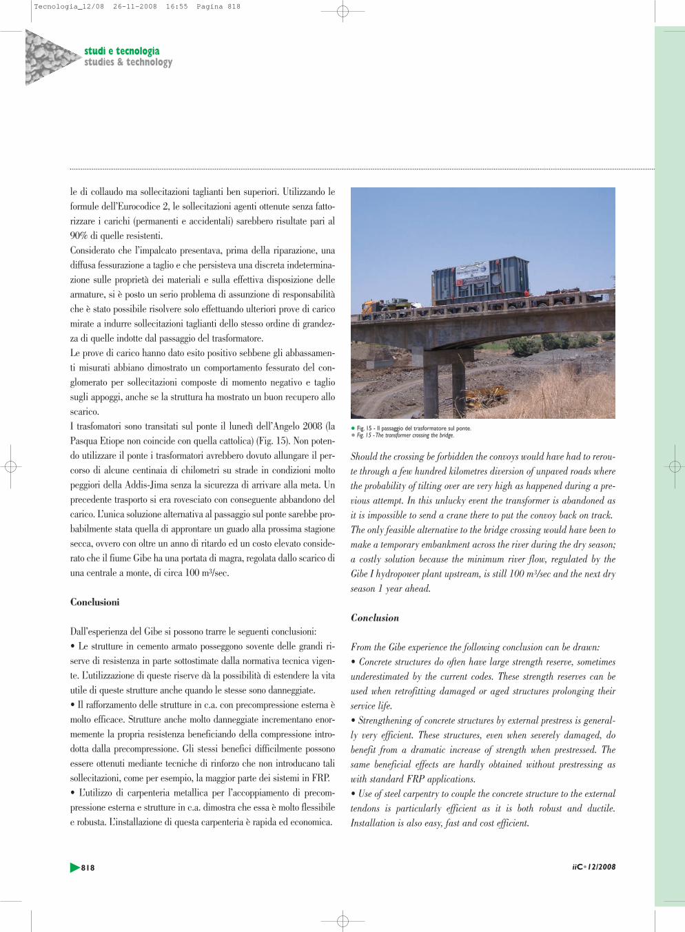
le di collaudo ma sollecitazioni taglianti ben superiori. Utilizzando leformule dell’Eurocodice 2, le sollecitazioni agenti ottenute senza fatto-rizzare i carichi (permanenti e accidentali) sarebbero risultate pari al90% di quelle resistenti.Considerato che l’impalcato presentava, prima della riparazione, unadiffusa fessurazione a taglio e che persisteva una discreta indetermina-zione sulle proprietà dei materiali e sulla effettiva disposizione dellearmature, si è posto un serio problema di assunzione di responsabilitàche è stato possibile risolvere solo effettuando ulteriori prove di caricomirate a indurre sollecitazioni taglianti dello stesso ordine di grandez-za di quelle indotte dal passaggio del trasformatore.Le prove di carico hanno dato esito positivo sebbene gli abbassamen-ti misurati abbiano dimostrato un comportamento fessurato del con-glomerato per sollecitazioni composte di momento negativo e tagliosugli appoggi, anche se la struttura ha mostrato un buon recupero alloscarico.I trasfomatori sono transitati sul ponte il lunedì dell’Angelo 2008 (laPasqua Etiope non coincide con quella cattolica) (Fig. 15). Non poten-do utilizzare il ponte i trasformatori avrebbero dovuto allungare il per-corso di alcune centinaia di chilometri su strade in condizioni moltopeggiori della Addis-Jima senza la sicurezza di arrivare alla meta. Unprecedente trasporto si era rovesciato con conseguente abbandono delcarico. L’unica soluzione alternativa al passaggio sul ponte sarebbe pro-babilmente stata quella di approntare un guado alla prossima stagionesecca, ovvero con oltre un anno di ritardo ed un costo elevato conside-rato che il fiume Gibe ha una portata di magra, regolata dallo scarico diuna centrale a monte, di circa 100 m3/sec.
Conclusioni
Dall’esperienza del Gibe si possono trarre le seguenti conclusioni:• Le strutture in cemento armato posseggono sovente delle grandi ri-serve di resistenza in parte sottostimate dalla normativa tecnica vigen-te. L’utilizzazione di queste riserve dà la possibilità di estendere la vitautile di queste strutture anche quando le stesse sono danneggiate. • Il rafforzamento delle strutture in c.a. con precompressione esterna èmolto efficace. Strutture anche molto danneggiate incrementano enor-memente la propria resistenza beneficiando della compressione intro-dotta dalla precompressione. Gli stessi benefici difficilmente possonoessere ottenuti mediante tecniche di rinforzo che non introducano talisollecitazioni, come per esempio, la maggior parte dei sistemi in FRP. • L’utilizzo di carpenteria metallica per l’accoppiamento di precom-pressione esterna e strutture in c.a. dimostra che essa è molto flessibilee robusta. L’installazione di questa carpenteria è rapida ed economica.
Should the crossing be forbidden the convoys would have had to rerou-te through a few hundred kilometres diversion of unpaved roads wherethe probability of tilting over are very high as happened during a pre-vious attempt. In this unlucky event the transformer is abandoned asit is impossible to send a crane there to put the convoy back on track. The only feasible alternative to the bridge crossing would have been tomake a temporary embankment across the river during the dry season;a costly solution because the minimum river flow, regulated by theGibe I hydropower plant upstream, is still 100 m3/sec and the next dryseason 1 year ahead.
Conclusion
From the Gibe experience the following conclusion can be drawn:• Concrete structures do often have large strength reserve, sometimesunderestimated by the current codes. These strength reserves can beused when retrofitting damaged or aged structures prolonging theirservice life. • Strengthening of concrete structures by external prestress is general-ly very efficient. These structures, even when severely damaged, dobenefit from a dramatic increase of strength when prestressed. Thesame beneficial effects are hardly obtained without prestressing aswith standard FRP applications.• Use of steel carpentry to couple the concrete structure to the externaltendons is particularly efficient as it is both robust and ductile.Installation is also easy, fast and cost efficient.
818 iiC•12/2008
studi e tecnologiastudies & technology
• Fig. 15 - Il passaggio del trasformatore sul ponte.• Fig. 15 - The transformer crossing the bridge.
Tecnologia_12/08 26-11-2008 16:55 Pagina 818

Il Ponte sul fiume Gibe è ubicato a 185 km da AddisAbeba, lungo un’arteria di interesse nazionale. Nel
corso della sua vita di esercizio, la struttura è stata messaa rischio più volte da una serie di eventi (non ultimi quel-li bellici) che ne ha compromesso l’intergità e la funzio-nalità. Nel 2006, un crollo di parte della struttura, acausa di un carico fuori sagoma, ha costretto le autoritàlocali ad intervenire in modo definitivo disponendo larealizzazione di un nuovo attraversamento – che è già infase di costruzione – qualche decina di metri a monte delponte esistente. La messa in esercizio della nuova opera èprevista però non prima di 2-3 anni e nel frattempo èstato deliberato un intervento rapido di riabilitazione delponte in c.a. esistente. I lavori, completati nel giro di 3mesi, hanno permesso di riaprire al traffico il ponte senzaalcuna limitazione di carico. Il ponte è una struttura incemento armato ad impalcato continuo, di lunghezzacomplessiva pari a 120,50 m, diviso in 4 campate: lastruttura portante è costituita da 4 travi longitudinali, dilarghezza pari a 400 mm e altezza variabile, connessetrasversalmente dalla soletta superiore, di spessore 180mm. Il grave quadro fessurativo dell’impalcato e la con-seguente modesta riserva di resistenza non permettevanointerventi mirati alla semplice ricostituzione dell’inte-grità strutturale (iniezione delle fessure, riparazioni loca-li). Considerato il relativo buono stato di conservazionedelle sottostrutture si è quindi ristretta la scelta dellesoluzioni possibili a quelle che avessero permesso il raffor-zamento dell’impalcato senza interruzione del traffico. Laconformazione geometrica dell’impalcato ha suggerito dimettere in opera un intervento basato sulla precompres-sione esterna. Prima dell’esecuzione delle operazioni ditesaggio sono comunque stati previsti interventi mirati alripristino dei calcestruzzi dell’impalcato.
The bridge over the Gibe river stands 185 km fromAddis Ababa, along an artery of national importan-
ce. During its operating lifetime the structure was put atrisk more than once by a series of events (not least war-caused) that compromised its integrity and function. In2006 a collapse of part of the structure owing to abeyond-clearance load constrained local authorities totake definitive action and arrange for the construction ofa new crossing – which is now under construction – a fewdozen meters upstream of the existing bridge. The newstructure is not envisaged however to go into operation fortwo or thee years. In the meanwhile a rapid operation torehabilitate the existing r.c. bridge was decided upon. Thejob, which was completed in three months, enabled reope-ning the bridge to traffic without any load limitation.The bridge is a reinforced-concrete structure with conti-nuous deck, a total 120.50 m long, on four spans. Thebearing structure consists of four longitudinal beams 400mm wide and of variable depth, connected crosswise bythe upper slab, 180 mm deep. The serious cracking of thedeck and its consequent modest reserve of strength did notpermit operations aimed at simply reconstituting structu-ral integrity (grouting of the cracks, local repairs).Considering the relatively good state of conservation of
Summary
Riassunto the understructures, the choice of possible solutions wasthus restricted to those that would permit strengtheningthe deck without interrupting traffic. The deck’s geometricconformation suggested an operation based on externalprestressing. Before the tensioning operations were car-ried out however, operations aimed at restoring the deckconcrete were called for.
Le pont sur le fleuve Gibe a été construit à une distan-ce de 185 kilomètres de Addis Ababa, le long d’une
artère d’intérêt national. Pendant la durée de son exerci-ce, la structure a été exposée à des risques plusieurs foissuite à une série d’évènements (pas en dernier lieu lesguerres), qui en ont compromis son intégrité et sa fonc-tion. En 2006 l’ effondrement d’une partie de la structure suiteà une charge hors gabarit, a obligé les autorités locales àintervenir de façon définitive en disposant la réalisationd’un nouveau pont pour traverser le fleuve – qui est déjàen cours de construction – à quelques dizaines de mètresen amont du pont existant. La mise en oeuvre du nouvelouvrage est prévue dans 2-3 ans, au plus tard, mais entre-temps une intervention rapide de réhabilitation du pontexistant en béton armé est devenue nécessaire. Les tra-vaux, achevés dans l’espace de trois mois, ont permis derouvrir à la circulation le pont sans aucune limitation decharge. Le pont est une structure en béton armé avec unplancher continu d’ une longueur totale de 120,50 m ,divisé en 4 travées: la structure portante est constituée de4 poutres longitudinales de 400 mm de large et avec unehauteur variable, ces poutres étant liées transversalementpar la semelle supérieure d’une épaisseur de 180 mm.L’état inquiétant des fissurations du plancher et la réser-ve de résistance modeste qui en résulte ne permettaientpas d’interventions visant la simple reconstitution del’intégrité structurale (injection dans les fissures, répara-tions locales). Compte tenu de l’état de conservation descouchis relativement satisfaisant, le choix des solutionspossibles s’est donc limité aux solutions, qui auraient per-mis le renforcement du plancher sans interrompre la cir-culation. La conformation géométrique du plancher asuggéré de mettre en oeuvre une intervention axée sur laprécontrainte extérieure. Avant d’exécuter les opérationsde tendage, ont été prévues de toute façon des interven-tions visant la restauration des bétons du plancher.
Die Brücke über den Fluss Gibe befindet sich 185 kmvon Addis Ababa entfernt, längs einer wichtigen
Nationalstrasse. Seit ihrer Entstehung wurde die Brückedurch verschiedene Ereignisse (nicht zuletzt durch kriege-rische Aktionen) bereits mehrmals starken Risiken ausge-setzt, die ihre Stabilität und Funktionsfähigkeit starkbeeinträchtigt haben. Im Jahr 2006 waren die Ver-waltungsbehörden auf Grund eines durch eine zu schwereLast bewirkten teilweisen Einbruchs der Struktur gezwun-gen, definitiv einzuschreiten und den Bau einer neuenBrücke zu veranlassen – der mittlerweile in Bau ist – undzwar einige Meter stromaufwärts der bestehendenStruktur. Die Inbetriebnahme des neuen Bauwerks wird
Zusammenfassung
Résumé
jedoch noch etwa 2-3 Jahre auf sich warten lassen; in derZwischenzeit wurde eine schnelle Reparatur der bestehen-den Stahlbetonbrücke beschlossen. Dank der in 3Monaten vollzogenen Arbeiten konnte die Brücke ohneLastbegrenzung wieder befahrbar gemacht werden. Beider Brücke handelt es sich um eine Struktur aus Stahl-beton mit durchlaufender Fahrbahn einer Gesamtlängevon 120,50 m, die in 4 Brückenfelder unterteilt ist: dieTrägerstruktur besteht aus 4 Längsträgern einer Längevon 400 mm und unterschiedlicher Höhe, die durch dieobere 180 mm starke Platte verbunden sind. Die starkenFahrbahnrisse und dementsprechend recht geringe Rest-stabilität ließen keine gezielten Eingriffe zur Wieder-herstellung der strukturellen Integrität zu (Zuspritzen derRisse, örtliche Reparaturen). Da die Unterstrukturenjedoch relativ gut erhalten waren, haben sich dieReparaturarbeiten auf eine Verstärkung der Brücken-balken konzentriert, ohne den Verkehr zu unterbrechen.Auf Grund der geometrischen Beschaffenheit derBrückenbalken wurde beschlossen, mit externer Vor-spannung vorzugehen. Vor Durchführung der Span-nungsarbeiten wurden jedoch gezielte Eingriffe vorge-nommen, um die Betonstruktur der Brückenbalken.auszubessern.
El puente en el río Gibe está ubicado a 185 km deAddis Ababa, a lo largo de una carretera de impor-
tancia nacional. En el curso de su vida útil, la estructu-ra ha estado a riesgo varias veces por algunos aconteci-mientos (también bélicos) que han perjudicado su inte-gridad y funcionalidad. En 2006, un derrumbe parcialde la estructura debido a una carga fuera del límite, haobligado las autoridades a intervenir de manera definiti-va disponiendo la realización de un nuevo puente –que yaestá en fase de construcción- algunas decenas de metrosantes del puente existente. La puesta en funcionamientode la nueva obra está prevista dentro de 2-3 años y mien-tras tanto se ha deliberado una intervención rápida derehabilitación del puente de hormigón armado existente.Los trabajos se han finalizado en tres meses y han permi-tido volver a abrir al tráfico el puente sin ninguna limi-tación de carga. El puente es una estructura de hormigónarmado de tablero continuo, con una longitud total de120,50 m, dividido en 4 tramos: la estructura portanteestá constituida por 4 vigas longitudinales con unaanchura de 400 mm y altura variable, conectadas tran-sversalmente por la losa superior de 180 mm de espesor.La grave situación de fisuración del tablero y la consi-guiente reducida reserva de resistencia no permitíanrestablecer simplemente la integridad estructural (inyec-ción de las fisuras, reparaciones locales). Teniendo encuenta el buen estado de conservación de las subestructu-ras, la posibilidad de elección se ha limitado a las solu-ciones que permitieran reforzar el tablero sin interrumpirel tráfico. La conformación geométrica del tablero hasugerido la realización de una intervención basada en elpretensado externo. Antes de realizar las operaciones detensado se han previsto intervenciones para renovar elhormigón del tablero.
Resumen
819iiC•12/2008
studi e tecnologiastudies & technology
Tecnologia_12/08 26-11-2008 16:55 Pagina 819