
TEORIA DELLE VIBRAZIONI MECCANICHE ... - karanasios.eu · I sistemi vibranti che costituiscono...
43
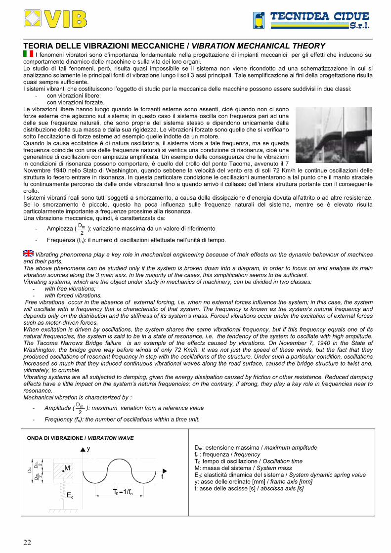
22 TEORIA DELLE VIBRAZIONI MECCANICHE / VIBRATION MECHANICAL THEORY I fenomeni vibratori sono d’importanza fondamentale nella progettazione di impianti meccanici per gli effetti che inducono sul comportamento dinamico delle macchine e sulla vita dei loro organi. Lo studio di tali fenomeni, però, risulta quasi impossibile se il sistema non viene ricondotto ad una schematizzazione in cui si analizzano solamente le principali fonti di vibrazione lungo i soli 3 assi principali. Tale semplificazione ai fini della progettazione risulta quasi sempre sufficiente. I sistemi vibranti che costituiscono l’oggetto di studio per la meccanica delle macchine possono essere suddivisi in due classi: - con vibrazioni libere; - con vibrazioni forzate. Le vibrazioni libere hanno luogo quando le forzanti esterne sono assenti, cioè quando non ci sono forze esterne che agiscono sul sistema; in questo caso il sistema oscilla con frequenza pari ad una delle sue frequenze naturali, che sono proprie del sistema stesso e dipendono unicamente dalla distribuzione della sua massa e dalla sua rigidezza. Le vibrazioni forzate sono quelle che si verificano sotto l’eccitazione di forze esterne ad esempio quelle indotte da un motore. Quando la causa eccitatrice è di natura oscillatoria, il sistema vibra a tale frequenza, ma se questa frequenza coincide con una delle frequenze naturali si verifica una condizione di risonanza, cioè una generatrice di oscillazioni con ampiezza amplificata. Un esempio delle conseguenze che le vibrazioni in condizioni di risonanza possono comportare, è quello del crollo del ponte Tacoma, avvenuto il 7 Novembre 1940 nello Stato di Washington, quando sebbene la velocità del vento era di soli 72 Km/h le continue oscillazioni delle struttura lo fecero entrare in risonanza. In questa particolare condizione le oscillazioni aumentarono a tal punto che il manto stradale fu continuamente percorso da delle onde vibrazionali fino a quando arrivò il collasso dell’intera struttura portante con il conseguente crollo. I sistemi vibranti reali sono tutti soggetti a smorzamento, a causa della dissipazione d’energia dovuta all’attrito o ad altre resistenze. Se lo smorzamento è piccolo, questo ha poca influenza sulle frequenze naturali del sistema, mentre se è elevato risulta particolarmente importante a frequenze prossime alla risonanza. Una vibrazione meccanica, quindi, è caratterizzata da: - Ampiezza ( 2 D m ): variazione massima da un valore di riferimento - Frequenza (f n ): il numero di oscillazioni effettuate nell’unità di tempo. Vibrating phenomena play a key role in mechanical engineering because of their effects on the dynamic behaviour of machines and their parts. The above phenomena can be studied only if the system is broken down into a diagram, in order to focus on and analyse its main vibration sources along the 3 main axis. In the majority of the cases, this simplification seems to be sufficient. Vibrating systems, which are the object under study in mechanics of machinery, can be divided in two classes: - with free vibrations; - with forced vibrations. Free vibrations occur in the absence of external forcing, i.e. when no external forces influence the system; in this case, the system will oscillate with a frequency that is characteristic of that system. The frequency is known as the system’s natural frequency and depends only on the distribution and the stiffness of its system’s mass. Forced vibrations occur under the excitation of external forces such as motor-driven forces. When excitation is driven by oscillations, the system shares the same vibrational frequency, but if this frequency equals one of its natural frequencies, the system is said to be in a state of resonance, i.e. the tendency of the system to oscillate with high amplitude. The Tacoma Narrows Bridge failure is an example of the effects caused by vibrations. On November 7, 1940 in the State of Washington, the bridge gave way before winds of only 72 Km/h. It was not just the speed of these winds, but the fact that they produced oscillations of resonant frequency in step with the oscillations of the structure. Under such a particular condition, oscillations increased so much that they induced continuous vibrational waves along the road surface, caused the bridge structure to twist and, ultimately, to crumble. Vibrating systems are all subjected to damping, given the energy dissipation caused by friction or other resistance. Reduced damping effects have a little impact on the system’s natural frequencies; on the contrary, if strong, they play a key role in frequencies near to resonance. Mechanical vibration is characterized by : - Amplitude ( 2 D m ): maximum variation from a reference value - Frequency (f n ): the number of oscillations within a time unit. ONDA DI VIBRAZIONE / VIBRATION WAVE y n 0 T =1/f t D 2 D 2 m m m E M d D m : estensione massima / maximum amplitude f n : frequenza / frequency T 0 : tempo di oscillazione / Oscillation time M: massa del sistema / System mass E d : elasticità dinamica del sistema / System dynamic spring value y: asse delle ordinate [mm] / frame axis [mm] t: asse delle ascisse [s] / abscissa axis [s]
Transcript of TEORIA DELLE VIBRAZIONI MECCANICHE ... - karanasios.eu · I sistemi vibranti che costituiscono...
22
TEORIA DELLE VIBRAZIONI MECCANICHE / VIBRATION MECHANICAL THEORY I fenomeni vibratori sono d’importanza fondamentale nella progettazione di impianti meccanici per gli effetti che inducono sul
comportamento dinamico delle macchine e sulla vita dei loro organi. Lo studio di tali fenomeni, però, risulta quasi impossibile se il sistema non viene ricondotto ad una schematizzazione in cui si analizzano solamente le principali fonti di vibrazione lungo i soli 3 assi principali. Tale semplificazione ai fini della progettazione risulta quasi sempre sufficiente. I sistemi vibranti che costituiscono l’oggetto di studio per la meccanica delle macchine possono essere suddivisi in due classi:
- con vibrazioni libere; - con vibrazioni forzate.
Le vibrazioni libere hanno luogo quando le forzanti esterne sono assenti, cioè quando non ci sono forze esterne che agiscono sul sistema; in questo caso il sistema oscilla con frequenza pari ad una delle sue frequenze naturali, che sono proprie del sistema stesso e dipendono unicamente dalla distribuzione della sua massa e dalla sua rigidezza. Le vibrazioni forzate sono quelle che si verificano sotto l’eccitazione di forze esterne ad esempio quelle indotte da un motore. Quando la causa eccitatrice è di natura oscillatoria, il sistema vibra a tale frequenza, ma se questa frequenza coincide con una delle frequenze naturali si verifica una condizione di risonanza, cioè una generatrice di oscillazioni con ampiezza amplificata. Un esempio delle conseguenze che le vibrazioni in condizioni di risonanza possono comportare, è quello del crollo del ponte Tacoma, avvenuto il 7 Novembre 1940 nello Stato di Washington, quando sebbene la velocità del vento era di soli 72 Km/h le continue oscillazioni delle struttura lo fecero entrare in risonanza. In questa particolare condizione le oscillazioni aumentarono a tal punto che il manto stradale fu continuamente percorso da delle onde vibrazionali fino a quando arrivò il collasso dell’intera struttura portante con il conseguente crollo. I sistemi vibranti reali sono tutti soggetti a smorzamento, a causa della dissipazione d’energia dovuta all’attrito o ad altre resistenze. Se lo smorzamento è piccolo, questo ha poca influenza sulle frequenze naturali del sistema, mentre se è elevato risulta particolarmente importante a frequenze prossime alla risonanza. Una vibrazione meccanica, quindi, è caratterizzata da:
- Ampiezza (2
Dm ): variazione massima da un valore di riferimento
- Frequenza (fn): il numero di oscillazioni effettuate nell’unità di tempo.
Vibrating phenomena play a key role in mechanical engineering because of their effects on the dynamic behaviour of machines and their parts. The above phenomena can be studied only if the system is broken down into a diagram, in order to focus on and analyse its main vibration sources along the 3 main axis. In the majority of the cases, this simplification seems to be sufficient. Vibrating systems, which are the object under study in mechanics of machinery, can be divided in two classes:
- with free vibrations; - with forced vibrations.
Free vibrations occur in the absence of external forcing, i.e. when no external forces influence the system; in this case, the system will oscillate with a frequency that is characteristic of that system. The frequency is known as the system’s natural frequency and depends only on the distribution and the stiffness of its system’s mass. Forced vibrations occur under the excitation of external forces such as motor-driven forces. When excitation is driven by oscillations, the system shares the same vibrational frequency, but if this frequency equals one of its natural frequencies, the system is said to be in a state of resonance, i.e. the tendency of the system to oscillate with high amplitude. The Tacoma Narrows Bridge failure is an example of the effects caused by vibrations. On November 7, 1940 in the State of Washington, the bridge gave way before winds of only 72 Km/h. It was not just the speed of these winds, but the fact that they produced oscillations of resonant frequency in step with the oscillations of the structure. Under such a particular condition, oscillations increased so much that they induced continuous vibrational waves along the road surface, caused the bridge structure to twist and, ultimately, to crumble. Vibrating systems are all subjected to damping, given the energy dissipation caused by friction or other resistance. Reduced damping effects have a little impact on the system’s natural frequencies; on the contrary, if strong, they play a key role in frequencies near to resonance. Mechanical vibration is characterized by :
- Amplitude (2
Dm ): maximum variation from a reference value
- Frequency (fn): the number of oscillations within a time unit.
ONDA DI VIBRAZIONE / VIBRATION WAVE
y
n0T =1/f
tD 2D 2
m
mm
E
M
d
Dm: estensione massima / maximum amplitude fn : frequenza / frequency T0
: tempo di oscillazione / Oscillation time M: massa del sistema / System mass Ed: elasticità dinamica del sistema / System dynamic spring value y: asse delle ordinate [mm] / frame axis [mm] t: asse delle ascisse [s] / abscissa axis [s]
23
TRASPORTATORI CON AZIONAMENTO BIELLA-MANOVELLA: INTRODUZIONE La tecnologia degli elementi elastici VIB permette di realizzare trasportatori oscillanti ad alto rendimento per il trasporto di materiale di differenti tipologie e pezzature. Gli elementi elastici VIB infatti permettono di costruire sistemi di trasporto che possono offrire notevoli vantaggi rispetto ai tradizionali sistemi:
- semplicità ed economicità nella progettazione e costruzione - elevata durata nel tempo con una limitata manutenzione - innumerevoli soluzioni applicative: trasportatori, vagli, calibratori, agitatori, setacciatori etc.
I canali vibranti sono costruiti con gli elementi oscillanti VIB che permettono di propagare le vibrazioni generate da un eccentrico lungo il piano di avanzamento del materiale. I trasportatori vibranti realizzati con la tecnologia VIB permette di progettare e costruire sia canali vibranti ad avanzamento fluido (trasporto) sia a saltellamento (vagliatura e calibrazione). I canali vibranti ad avanzamento fluido sono utilizzati con basse frequenze (2 Hz) ed elevate ampiezze (max circa 30 cm) e sono particolarmente utilizzati per il trasporto di materiale di elevate dimensioni. I trasportatori a saltellamento lavorano con frequenza elevata (fino a 10 Hz) e con ampiezze ridotte (max circa 2 cm). Queste tipologie di trasportatori sono particolarmente utilizzati nell’industria mineraria-estrattiva, lavorazione frutta e verdura, lavorazione tabacco, riciclaggio, setacciatura farine, miscelatura mangimi etc.
CONVEYORS ACTUATED BY A CONNECTING ROD-CRANK DEVICE: INTRODUCTION VIB elastic elements are engineered in order to obtain high-performance oscillating conveyors that carry material of different type and size. VIB elastic elements have suitable features for the production of highly advanced conveyors compared to the traditional ones and provide the following improvements:
- engineering and production is facilitated and money-saving - long life and reduced maintenance - multi-faceted applications/solutions: conveyors, screens, calibrators, stirrers, etc.
The vibrating channels produced with VIB oscillating elements allow to propagate the vibrations generated by an eccentric along the forward plane of the material. Vibrating conveyors - backed by the VIB technology - may be used to design and produce vibrating channels for fluid conveyance as well as hopping channels (screening and calibration). Fluid vibrating channels are used at low frequencies (2Hz) and high amplitudes (max approx. 30 cm) and are ideal for bulky material. Hopping conveyors work at high frequencies (up to 10 Hz) and reduced amplitudes (max approx. 2 cm). These conveyors are largely used in the mining-quarrying industry, fruit and vegetable processing, tobacco processing, recycling, flour sifting, fodder mixing, etc.
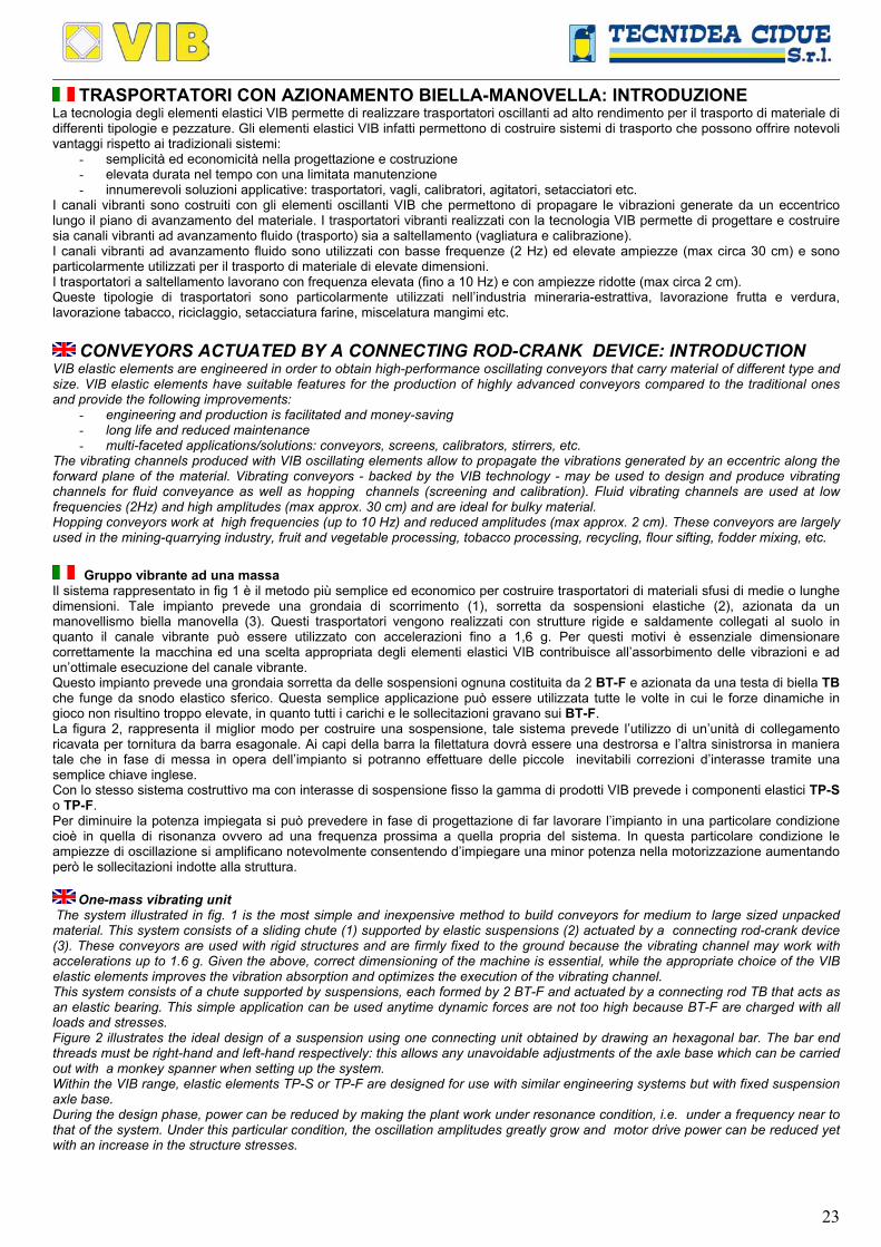
Gruppo vibrante ad una massa Il sistema rappresentato in fig 1 è il metodo più semplice ed economico per costruire trasportatori di materiali sfusi di medie o lunghe dimensioni. Tale impianto prevede una grondaia di scorrimento (1), sorretta da sospensioni elastiche (2), azionata da un manovellismo biella manovella (3). Questi trasportatori vengono realizzati con strutture rigide e saldamente collegati al suolo in quanto il canale vibrante può essere utilizzato con accelerazioni fino a 1,6 g. Per questi motivi è essenziale dimensionare correttamente la macchina ed una scelta appropriata degli elementi elastici VIB contribuisce all’assorbimento delle vibrazioni e ad un’ottimale esecuzione del canale vibrante. Questo impianto prevede una grondaia sorretta da delle sospensioni ognuna costituita da 2 BT-F e azionata da una testa di biella TB che funge da snodo elastico sferico. Questa semplice applicazione può essere utilizzata tutte le volte in cui le forze dinamiche in gioco non risultino troppo elevate, in quanto tutti i carichi e le sollecitazioni gravano sui BT-F. La figura 2, rappresenta il miglior modo per costruire una sospensione, tale sistema prevede l’utilizzo di un’unità di collegamento ricavata per tornitura da barra esagonale. Ai capi della barra la filettatura dovrà essere una destrorsa e l’altra sinistrorsa in maniera tale che in fase di messa in opera dell’impianto si potranno effettuare delle piccole inevitabili correzioni d’interasse tramite una semplice chiave inglese. Con lo stesso sistema costruttivo ma con interasse di sospensione fisso la gamma di prodotti VIB prevede i componenti elastici TP-S o TP-F. Per diminuire la potenza impiegata si può prevedere in fase di progettazione di far lavorare l’impianto in una particolare condizione cioè in quella di risonanza ovvero ad una frequenza prossima a quella propria del sistema. In questa particolare condizione le ampiezze di oscillazione si amplificano notevolmente consentendo d’impiegare una minor potenza nella motorizzazione aumentando però le sollecitazioni indotte alla struttura.
One-mass vibrating unit The system illustrated in fig. 1 is the most simple and inexpensive method to build conveyors for medium to large sized unpacked material. This system consists of a sliding chute (1) supported by elastic suspensions (2) actuated by a connecting rod-crank device (3). These conveyors are used with rigid structures and are firmly fixed to the ground because the vibrating channel may work with accelerations up to 1.6 g. Given the above, correct dimensioning of the machine is essential, while the appropriate choice of the VIB elastic elements improves the vibration absorption and optimizes the execution of the vibrating channel. This system consists of a chute supported by suspensions, each formed by 2 BT-F and actuated by a connecting rod TB that acts as an elastic bearing. This simple application can be used anytime dynamic forces are not too high because BT-F are charged with all loads and stresses. Figure 2 illustrates the ideal design of a suspension using one connecting unit obtained by drawing an hexagonal bar. The bar end threads must be right-hand and left-hand respectively: this allows any unavoidable adjustments of the axle base which can be carried out with a monkey spanner when setting up the system. Within the VIB range, elastic elements TP-S or TP-F are designed for use with similar engineering systems but with fixed suspension axle base. During the design phase, power can be reduced by making the plant work under resonance condition, i.e. under a frequency near to that of the system. Under this particular condition, the oscillation amplitudes greatly grow and motor drive power can be reduced yet with an increase in the structure stresses.

24
I
90°
Lf
Re3
1
G
B
4
2c
LoadingCarico Feed direction
Verso di avanzamento
ScaricoDischarge
Fig.1
Re
I4
min
1.5
-2xS
Fig.2
Legenda / Key: 1: Grondaia di scorrimento / Sliding chute 2: Sospensione VIB tipo BT-F / BT-F suspension 3: Testa di biella VIB tipo TB / TB Drive head 4: Unità di collegamento / Connecting rod B: Baricentro / Center of gravity G: Peso / Weight I: Interasse / Distance between centers Lf: Lunghezza minima del tratto filettato (1.5-2 S) IIIIIMin Screwed-in lenght (1.5-2 S) S: Diametro filettato della testa di biella tipo VIB iiiiiitipo TB o BT-F Threaded diameter inside itypes TB or BT-F Re: Raggio della manovella / Sliding crank radius α: Angolo di montaggio da 20° a 30° Rocker angle from 20° to 30° β: Angolo di lavoro max 10° Working angle max10°
Gruppo vibrante bilanciato con massa e contromassa Quando le forze dinamiche ed inerziali sono elevate e si richiede al trasportatore elevate prestazioni ed efficienza è consigliabile l’utilizzo di un sistema di oscillazione con massa e contromassa, in quanto le sollecitazioni non vengono scaricate interamente alle fondazioni ma compensate dinamicamente dalle due masse oscillanti. La figura 3 rappresenta lo schema di un trasportatore oscillante a due masse bilanciate con azionamento biella manovella. Questo impianto prevede una grondaia sorretta delle sospensioni TD-S e azionata da un elemento elastico AD-P che funge da snodo elastico. In questi trasportatori a due masse l’azionamento può essere applicato indifferentemente al canale di scivolamento superiore o alla contromassa inferiore. In alternativa ai TD-S è possibile utilizzare i TD-F, questi prodotti si differenziano solamente per le differenti modalità di montaggio, che sono di seguito illustrate. Il canale di scivolamento (1) e la contromassa (2) hanno lo stesso peso, quindi le due masse durante le loro oscillazioni si equilibrano dinamicamente in quanto l’una si muove in senso opposto all’altra. Questo sistema, inoltre, permette di sfruttare l’oscillazione della contromassa per realizzare un secondo canale di scivolamento con il medesimo verso di avanzamento di quello superiore.
Balanced vibrating unit with mass and counter mass With high dynamic and inertial forces, and any time there is the need for an efficient and high-performance conveyor, we recommend that you use an oscillation system with mass and counter mass because stresses are never completely discharged in foundations but dynamically compensated by the two oscillating masses. Figure 3 illustrates the diagram of a two-balanced-mass oscillating conveyor actuated by a connecting-rod/crank device. This plant consists of a chute supported by TD-S suspensions and enabled by an AD-P elastic element that acts as the elastic joint. These two-mass conveyors can be operated both from the upper sliding channel and the lower counter mass. As an alternative, TD-S can be replaced by TD-F which differs only in the coupling procedures as illustrated below. The sliding channel (1) and the counter mass (2) have the same weight. Therefore, while they oscillate, their two masses are dynamically balanced because one moves in the opposite direction to the other. This system also allows to exploit the oscillation of the counter mass to obtain a second sliding channel with the same direction of the upper one.
90°
Re
Verso di avanzamento 1
4
I
5
2
I 3
1
Verso di avanzamento 2
Carico
Scarico 1
Scarico 2
Loading
Feed direction 1
Feed direction 2
Discharge 1
Discharge 2
Fig.3
Legenda / Key: 1: Grondaia di scorrimento superiore / Superior sliding chute 2: Contromassa inferiore (Grondaia inferiore) iiiiiCounter mass (Inferior sliding chute) 3: Sospensione tipo VIB tipo TD-S / TD-S Suspension 4: Elemento oscillante VIB tipo AD-P / AD-P Oscillating Element 5: Basamento / Base plate α: Angolo di montaggio da 20° a 30° / Rocker angle from 20° to 30° β: Angolo di lavoro / Working angle I: Interasse / Distance between centers
Gruppo vibrante in risonanza I trasportatori vibranti ad una massa oppure quelli bilanciati a due masse possono essere progettati per lavorare in un regime dinamico di risonanza, con lo scopo di aumentare le ampiezze di oscillazione e contemporaneamente ridurre la potenza richiesta dal sistema. Questa condizione, però, comporta l’utilizzo di un numero maggiore di sospensioni elastiche rispetto ad un regime dinamico non in risonanza. I componenti elastici VIB permettono, infatti, di fornire la necessaria elasticità dinamica al sistema per un funzionamento nella condizione di risonanza, evitando però che le vibrazioni si propaghino alla struttura della macchina ed al suolo tramite le fondazioni.
Resonance vibrating unit One-mass or two-mass-balanced vibrating conveyors can be designed to work under resonance dynamic regimen in order to increase the oscillation amplitudes and at the same time reduce the power required by the system. This condition however involves a larger number of elastic suspensions compared to dynamic regimen out of resonance. VIB elastic elements provide the necessary dynamic elasticity to the system which can operate under resonance conditions but avoiding that vibrations propagate to the machine structure and, through the foundations, to the ground.

25
SISTEMI DI CALCOLO E FORMULE / CALCULATION SYSTEMS AND FORMULA Nomenclatura / Nomenclature:
Simbolo Symbol
Descrizione Description
Unità di misura Measure unit
Simbolo Symbol
Descrizione Description
Unità di misura Measure unit
α Angolo di montaggio Rocker angle [°] g Accelerazione di gravità
Gravitational acceleration 9,81 [m/s2]
β Angolo di lavoro Working angle [°] I Interasse
Distance between centers [mm]
γ Angolo di oscillazione Oscillation angle [°] J Indice della macchina
Machine factor
B Baricentro Center of gravity m Massa
Mass [Kg]
Dm Estensione max Maximum amplitude [mm] Md
Coppia dinamica Dynamic torque [Nm/°]
Ed Elasticità dinamica
Dynamic spring value [N/mm] n Velocità di rotazione Rotation Velocity [min-1]
Et Elasticità totale
Total spring value [N/mm] Re Raggio della manovella
Crank radius [mm]
fn Frequenza naturale
Own frequency [Hz] Va Velocità teorica di avanzamento
del materiale Theoretical feed velocity of the
material
[m/min]
f0 Frequenza ingresso nel sistema
Entrance frequency in the system [Hz] Vr Velocità reale di avanzamento del
materiale Real feed velocity of the material
[m/min]
F Forza di slancio Acceleration force [N] W Potenza teorica sull’albero dell’eccentrico
Theoretical driving power on crank shaft [kW]
G Peso Weight [N] λ
Coefficiente di riduzione velocità di avanzamento
Reduction coefficient feed velocity
Principali formule di calcolo / Main calculation formula:
Formula / Formula Unità di misura Measure unit Formula / Formula Unità di misura
Measure unit
G = m·g [N] f0 =60n
[Hz]
Et = 0,001·2
n602m
⋅π
⋅ [N/mm] F = J·m·g [N]
J = 9810
Rn602
e
2⋅
⋅π
Vr = Va · λ [m/min]
Dm = 2·Re [mm] W = 2100029550
ngmJDm
⋅⋅⋅
⋅⋅⋅⋅ [kW]

26
Grafico velocità teorica / Theoretical velocity graph:
30405060708090
100
3025201550 10 35 40
10
45 50 55
20
Crank radius Re in (mm)
Vel
ocità
teor
ica
V
in (m
/min
)
J=6
J=4
J=5
J=2
J=3600 min-1
540 min-1
480 min-1
300 min-1
360 min-1
420 min-1
a
Re
Va
Theo
retic
al v
eloc
ity V
in
(m/m
in)
a
Raggio dell' eccentrico Re in (mm)
Questo grafico consente di determinare la velocità di avanzamento teorica del materiale in un trasportatore ad azionamento
biella manovella avente le sospensioni montate con un angolo α=30°. La velocità reale di avanzamento Vr dipende però dalla tipologia di prodotto trasportato. La velocità reale Vr è data dalla relazione: Vr = Va · λ Dove λ è il coefficiente di riduzione dovuto alla coesione dipendente dalla tipologia del materiale da trasportare.
This graph shows the theoretical feed velocity of the material on a conveyor actuated by the connecting-rod/crank device with suspensions mounted at an angle of α=30°. Real feed velocity Vr depends on the type of product fed. Real velocity Vr is the result of the relation: Vr = Va · λ where λ is the reduction coefficient due to the cohesion that depends on the type of material to be conveyed.
Tipologia di prodotto trasportato Carried product type λ Tipologia di prodotto trasportato
Carried product type λ
Ghiaia Gravel 0,95 Trucioli di legno
Wood chips 0,75
Sabbia Sand 0,70 Verdura a foglie
Leaf vegetable 0,70
Carbone (granulometria fine) Coal (small granulometry) 0,80 Zucchero
Sugar 0,85
Carbone (granulometria elevata) Coal (coarse granulometry) 0,85 Sale
Salt 0,95
ESEMPIO DI CALCOLO:Determinazione della velocità reale del materiale in un trasportatore per ghiaia con azionamento biella e manovella montato con sospensioni elastiche VIB
CALCULATION EXAMPLE: Determination of the real velocity of the material on a gravel conveyor actuated by a connecting rod/crank device with VIB elastic suspensions Dati iniziali / Given data:
n: Velocità di rotazione dell’eccentrico / Crank rotation velocity: 300 min-1
Re: Raggio della manovella / Crank radius: 20 mm α: Angolo di montaggio / Rocker angle: 30° λ: coefficiente di riduzione / Reduction coefficient feed velocity: 0,95 (ghiaia / gravel) Incognite / Unknow values: Va: Velocità di avanzamento teorica / Theoretical feed velocity Vr: Velocità di avanzamento reale / Real feed velocity Schema di calcolo / Calculation steps:
J: Indice della macchina vibrante / Oscillating machine factor = 0,29810
2030300
9810
Re60
n2 22
=⋅
⋅π
=⋅
⋅π⋅
Va: Velocità di avanzamento teorica (“ricavato dal “grafico velocità teorica”) Theoretical feed velocity = 20 m/min (obtained from “theorical velocity graph”) Vr: Velocità reale / Real feed velocity = Va · λ = 20 · 0,95 = 19 m/min.
27
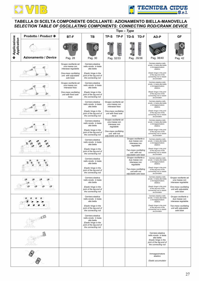
TABELLA DI SCELTA COMPONENTE OSCILLANTE: AZIONAMENTO BIELLA-MANOVELLA SELECTION TABLE OF OSCILLATING COMPONENTS: CONNECTING ROD/CRANK DEVICE
Tipo – Type Prodotto / Product
App
licaz
ione
A
pplic
atio
n
Azionamento / Device
BT-F
Pag. 28
TB
Pag. 30
TP-S TP-F
Pag. 32/33
TD-S TD-F
Pag. .35/36
AD-P
Pag. 38/40
GF
Pag. 42
Gruppo oscillante ad una massa con
interasse regolabile
One-mass oscillating unit with adjustable
axle base
Cerniera elastica nello snodo in testa
alla biella
Elastic hinge in the joint of the big end of the connecting rod
Cerniera elastica nello snodo in testa alla biella
o immagazzinatore elastico
Elastic hinge in the joint
of the big end of the connecting rod or elastic
accumulator
Gruppo oscillante ad una massa con interasse fisso
One-mass oscillating unit with fixed axle
base
Cerniera elastica nello snodo in testa
alla biella
Elastic hinge in the joint of the big end of the connecting rod
Cerniera elastica nello snodo in testa alla biella
o immagazzinatore elastico
Elastic hinge in the joint
of the big end of the connecting rod or elastic
accumulator
Cerniera elastica nello snodo in testa
alla biella
Elastic hinge in the joint of the big end of the connecting rod
Gruppo oscillante ad una massa con interasse fisso
One-mass oscillating
unit with fixed axle base
Cerniera elastica nello snodo in testa alla biella
o immagazzinatore elastico
Elastic hinge in the joint
of the big end of the connecting rod or elastic
accumulator
Cerniera elastica nello snodo in testa
alla biella
Elastic hinge in the joint of the big end of the connecting rod
Gruppo oscillante ad una massa con interasse non
regolabile
One-mass oscillating unit with not
adjustable axle base
Cerniera elastica nello snodo in testa alla biella
o immagazzinatore elastico
Elastic hinge in the joint
of the big end of the connecting rod or elastic
accumulator
Cerniera elastica nello snodo in testa
alla biella
Elastic hinge in the joint of the big end of the connecting rod
Gruppo oscillante a due masse con interasse non
regolabile
Two-mass oscillating unit with not
adjustable axle base
Cerniera elastica nello snodo in testa alla biella
o immagazzinatore elastico
Elastic hinge in the joint
of the big end of the connecting rod or elastic
accumulator
Cerniera elastica nello snodo in testa
alla biella
Elastic hinge in the joint of the big end of the connecting rod
Cerniera elastica nello snodo in testa alla biella
o immagazzinatore elastico
Elastic hinge in the joint
of the big end of the connecting rod or elastic
accumulator
Gruppo oscillante ad una massa con
interasse regolabile
One-mass oscillating unit with adjustable
axle base
Cerniera elastica nello snodo in testa
alla biella
Elastic hinge in the joint of the big end of the connecting rod
Cerniera elastica nello snodo in testa alla biella
o immagazzinatore elastico
Elastic hinge in the joint
of the big end of the connecting rod or elastic
accumulator
Gruppo oscillante a due masse con
interasse regolabile
Two-mass oscillating unit with adjustable
axle base
Cerniera elastica nello snodo in testa
alla biella Elastic hinge in the
joint of the big end of the connecting rod
Cerniera elastica nello snodo in testa
alla biella Elastic hinge in the
joint of the big end of the connecting rod
Immagazzinatore elastico
Elastic accumulator

28
Elementi Oscillanti VIB Tipo: BT-F / Oscillating mounting VIB Type: BT-F
CCCCCCCCCCCC CCCCCCCCCCCC
E
MA
SD
L1F
ØR
N
H
C
TAGLIA 20 / SIZES 20
A
SD
C
F
/ RN
E
H
TAGLIA 30, 40, 50 e 60 / SIZES 30, 40,50 and 60
/ R
N
FL1
AM
E
SD
C
H
TAGLIA 70 e 80 / SIZES 70 and 80
Q
n
Md
A
C
D
E
F
H
L1
M
N
P
R
S
Tipo Type
Cod. N°
Peso Weightin kg
BT-F 20 RE020584 96 1150 0,42 50 7 30 25 4 28 50 70 29 40 20 M10 0,28 BT-F 20 S RE020586 96 1150 0,42 50 7 30 25 4 28 50 70 29 40 20 M10S 0,28 BT-F 30 RE020588 197 1150 1,26 60 9,5 39 35 5 34 62 85 31,5 45 22 M12 0,35 BT-F 30 S RE020590 197 1150 1,26 60 9,5 39 35 5 34 62 85 31,5 45 22 M12S 0,35 BT-F 40 RE020592 385 750 2,5 80 11,5 54 45 5 40 73 110 40,5 60 28 M16 0,85 BT-F 40 S RE020594 385 750 2,5 80 11,5 54 45 5 40 73 110 40,5 60 28 M16S 0,85 BT-F 50 RE020596 765 750 6,4 100 14 74 60 6 52 95 140 53 80 42 M20 2,00 BT-F 50 S RE020598 765 750 6,4 100 14 74 60 6 52 95 140 53 80 42 M20S 2,00 BT-F 60 RE020600 1510 750 11,1 130 18 89 70 8 66 120 180 67 100 48 M24 2,55 BT-F 60 S RE020602 1510 750 11,1 130 18 89 70 8 66 120 180 67 100 48 M24S 2,55 BT-F 70 RE020604 2370 560 19,2 140 18 80 80 10 80 145 190 65 105 60 M36 8,50 BT-F 70 S RE020606 2370 560 19,2 140 18 80 80 10 80 145 190 65 105 60 M36S 8,50 BT-F 80 RE020608 4700 370 27,4 180 18 110 120 15 128 233 230 75 130 80 M42 20,00 BT-F 80 S RE020610 4700 370 27,4 180 18 110 120 15 128 233 230 75 130 80 M42S 20,00
Q: Carico max in N per sospensione / Max loading in N per rocker suspension
Velocità max di rotazione dell’eccentrico in min-1 per l’angolo max ≮10° con variazione ≮ ±5° dalla posizione 0 n: Max crank rotation velocity in min-1 at the max angle ≮10° from 0 ≮ ±5°
Md: Coppia dinamica in Nm/° per ≮ ±5°, tra il campo di frequenza da 300 a 600 min-1 / Dynamic torque in Nm/° at per ≮ ±5°, in frequency range 300-600 min-1
I
90°
Lf
Re3
1
G
B
4
2c
LoadingCarico Feed direction
Verso di avanzamento
ScaricoDischarge
Legenda / Key: 1: Grondaia di scorrimento / Sliding chute 2: Sospensione VIB tipo BT-F / BT-F suspension 3: Testa di biella VIB tipo TB / TB Drive head 4: Unità di collegamento / Connecting rod B: Baricentro / Centre of gravity G: Peso Totale / Total weight I: Interasse / Distance between centres Lf: Lunghezza minima del tratto filettato (1.5-2 S) / Min Screwed-in lenght (1.5-2 S) Re: Raggio della manovella / Crank radius α: Angolo di montaggio da 20° a 30° / Rocker angle from 20° to 30° β: Angolo di lavoro / Working angle
MATERIALI
Il corpo esterno è in acciaio nelle grandezze 20, 70 e 80; in alluminio nelle grandezze 30, 40, 50 e 60. Il quadro interno e la flangia sono in acciaio. TRATTAMENTI Il corpo esterno, il quadro interno e la flangia sono verniciati a forno. IMPIEGO Il componente oscillante BT-F è principalmente utilizzato per la realizzazione di sospensioni nei trasportatori e nei vagli vibranti ad azionamento biella/manovella.
MATERIALS The external body is made of steel in the sizes 20, 70 and 80, light metal die cast in the sizes 30, 40, 50 and 60. The inner square and the fixation flange are made of steel TREATMENTS The external body, the inner square and the fixation flange are oven-painted. DUTY BT-F Oscillating component is generally used to realize rocker suspension in conveyors and oscillating screens actuacted by connecting rod/crank device.

29
ESEMPIO DI CALCOLO: Determinazione del numero di sospensioni necessarie per un trasportatore vibrante, utilizzando dei gruppi composti da due BT-F 50
CALCULATION EXAMPLE: Determination of the mounting number for an oscillating conveyor using BT-F 50 type.
Dati iniziali / Given data:
Md: Coppia dinamica: Dynamic torque: 6,4 Nm/° (da catalogo/ catalogue) Gm: Peso del materiale da trasportare:
Material weight: 1000 N
n: Velocità di rotazione: Rotation velocity: 150 min-1 I: Lunghezza interasse sospensione:
Distance between centers: 250 mm
Gg: Peso della grondaia: Chute weight: 5580 N Re: Raggio della manovella:
Crank radius: 18 mm
Incognite / Unknow values:
X: numero di sospensioni da utilizzare / Number of mountings
Schema di calcolo / Calculation steps:
Ed: Elasticità dinamica / Dynamic spring value = 74,11250
10003604,6I
1000360M22
d =π⋅
⋅⋅=
π⋅
⋅⋅ N/mm
Il peso totale G è dato dalla somma del peso della grondaia (Gg) più il 22% del peso del materiale da trasportare (Gm) The total weight G is given by the sum of weight of the chute (Gg) plus 22% of the weight of the material to be conveyed (Gm)
G: Peso totale: Total weight: = Gg+ 5800
1002210005580
10022Gm =
⋅+=
⋅N
Et: Elasticità totale: Total spring value: = 7,145
30150
98105800
60n2
9810G 22
=
⋅π⋅=
⋅π⋅⋅ N/mm
1) In condizioni di non risonanza / Without resonance condition:
X:
Il numero di elementi X si ricava dividendo il peso totale della massa oscillante per il carico ammesso da una sospensione quindi:
The number of the elements X is obtained by dividing the total weight of the oscillating mass by the load permitted by one mounting, so:
= 58,7765
5800QG
== 8
Conclusione: Si devono utilizzare almeno 8 sospensioni ognuna formata da 2 elementi BT-F 50 Pezzi 16 BT-F 50. Conclusion: It must be used 8 mountings at least, each comprising 2 pcs BT-F 50 elements 16 pcs BT-F 50
2) In condizioni di risonanza / With resonance condition:
X:
L’elasticità totale Et della sospensione deve essere approssimativamente il 10% superiore a quello dell’elasticità dinamica, quindi:
The total spring value Et of the mounting must be at least 10% greater that than the dynamic spring value, so:
= 78,1374,119,0
7,145E9,0
E
d
t =⋅
=⋅
14
Conclusione: Si devono utilizzare 14 sospensioni ognuna formata da 2 elementi BT-F 50 Pezzi 28 BT-F 50. Conclusion: It must be used 14 mountings, each comprising 2 pcs BT-F 50 elements 28 pcs BT-F 50.
Per realizzare una sospensione con gli elementi BT-F consigliamo di rifarsi allo schema proposto in figura 1. Questo sistema prevede l’utilizzo di un’unità di collegamento (4) avente ai capi una filettatura inversa (una destrorsa e l’altra sinistrorsa), ricavata per tornitura da barra esagonale. Assemblando poi per ogni sospensione un BT-F ad un BT-F S attraverso una chiave inglese si riuscirà a livellare la grondaia di scorrimento del materiale.
We recommend that you follow the diagram of figure 1 in order to make a suspension with the BT- F elements. This system focuses on the use of a link unit (4) with opposite threaded ends (right-hand and left-hand) obtained by drawing an hexagonal bar. By assembling one BT-F and one BT-F S for each suspension, with a monkey spanner you can level the chute where the material is being conveyed.
La figura 2 rappresenta lo schema di una sospensione con interasse non regolabile. Questo sistema prevede l’utilizzo di un’unità di collegamento (4) realizzata con una barra filettata, avente ai capi due BT-F con il medesimo filetto (destro o sinistro). Una volta che questa sospensione è fissata al canale non è più possibile fare regolazioni d’interasse.
Figure 2 represents the diagram of a suspension with non adjustable axle base. This system can be operated with a link unit (4) from a threaded bar with two BT-F mounted at both ends with the same thread (right-hand or left-hand). Once the suspension has been fixed to the channel, the axle base cannot be further adjusted.
I
Re
4
Fig 2
I
Re
4
Fig 1
30
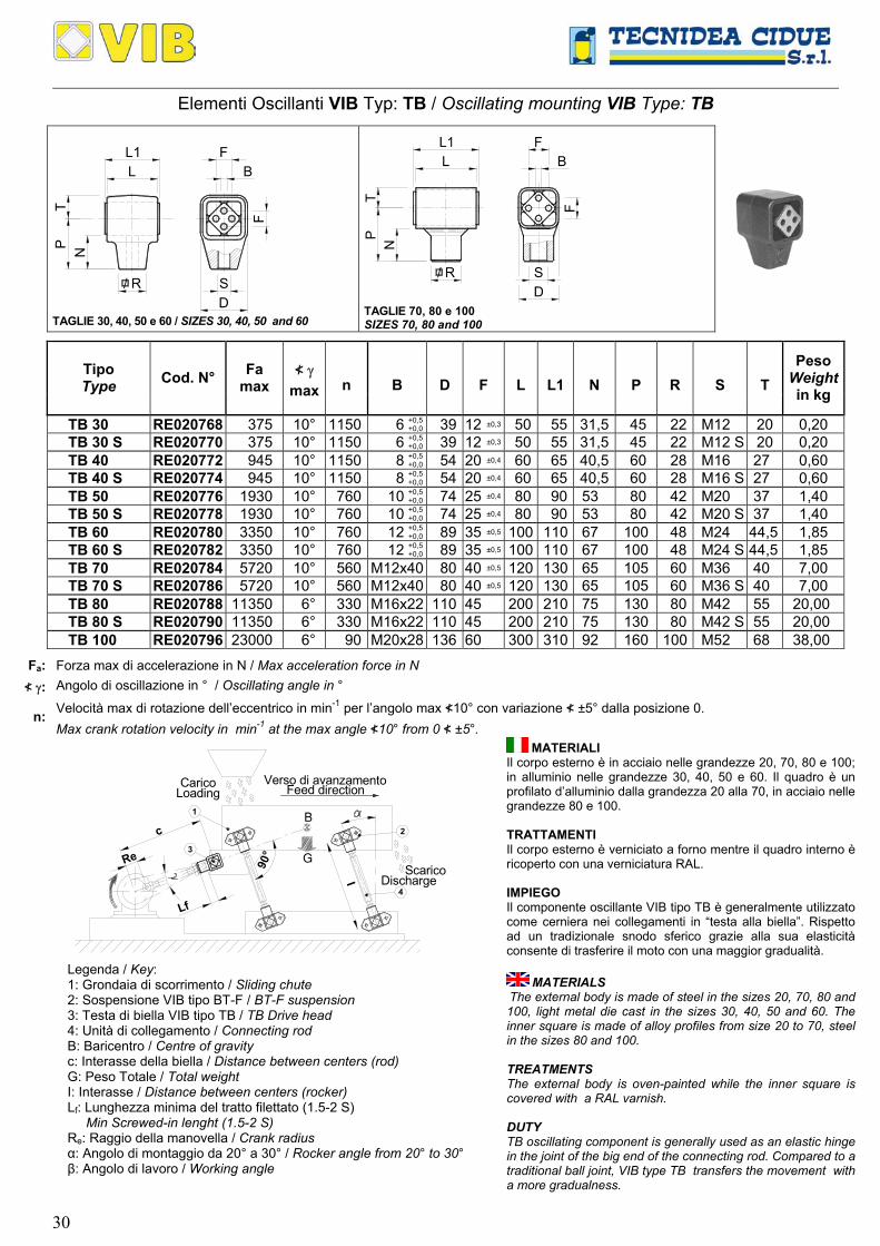
Elementi Oscillanti VIB Typ: TB / Oscillating mounting VIB Type: TB
SD
/ R
NP
F
B
T
L
TAGLIE 30, 40, 50 e 60 / SIZES 30, 40, 50 and 60
/ R SD
NP
T
B
F
L
TAGLIE 70, 80 e 100 SIZES 70, 80 and 100
n
B
D
F
L
L1
N
P
R
S
T Tipo Type Cod. N° Fa
max ≮ γ
max
Peso Weightin kg
TB 30 RE020768 375 10° 1150 6 +0,5+0,0 39 12 ±0,3 50 55 31,5 45 22 M12 20 0,20
TB 30 S RE020770 375 10° 1150 6 +0,5+0,0 39 12 ±0,3 50 55 31,5 45 22 M12 S 20 0,20
TB 40 RE020772 945 10° 1150 8 +0,5+0,0 54 20 ±0,4 60 65 40,5 60 28 M16 27 0,60
TB 40 S RE020774 945 10° 1150 8 +0,5+0,0 54 20 ±0,4 60 65 40,5 60 28 M16 S 27 0,60
TB 50 RE020776 1930 10° 760 10 +0,5+0,0 74 25 ±0,4 80 90 53 80 42 M20 37 1,40
TB 50 S RE020778 1930 10° 760 10 +0,5+0,0 74 25 ±0,4 80 90 53 80 42 M20 S 37 1,40
TB 60 RE020780 3350 10° 760 12 +0,5+0,0 89 35 ±0,5 100 110 67 100 48 M24 44,5 1,85
TB 60 S RE020782 3350 10° 760 12 +0,5+0,0 89 35 ±0,5 100 110 67 100 48 M24 S 44,5 1,85
TB 70 RE020784 5720 10° 560 M12x40 80 40 ±0,5 120 130 65 105 60 M36 40 7,00 TB 70 S RE020786 5720 10° 560 M12x40 80 40 ±0,5 120 130 65 105 60 M36 S 40 7,00 TB 80 RE020788 11350 6° 330 M16x22 110 45 200 210 75 130 80 M42 55 20,00 TB 80 S RE020790 11350 6° 330 M16x22 110 45 200 210 75 130 80 M42 S 55 20,00 TB 100 RE020796 23000 6° 90 M20x28 136 60 300 310 92 160 100 M52 68 38,00
Fa: Forza max di accelerazione in N / Max acceleration force in N
≮ γ: Angolo di oscillazione in ° / Oscillating angle in °
Velocità max di rotazione dell’eccentrico in min-1 per l’angolo max ≮10° con variazione ≮ ±5° dalla posizione 0. n: Max crank rotation velocity in min-1 at the max angle ≮10° from 0 ≮ ±5°.
I
90°
Lf
Re3
1
G
B
4
2c
LoadingCarico Feed direction
Verso di avanzamento
ScaricoDischarge
Legenda / Key: 1: Grondaia di scorrimento / Sliding chute 2: Sospensione VIB tipo BT-F / BT-F suspension 3: Testa di biella VIB tipo TB / TB Drive head 4: Unità di collegamento / Connecting rod B: Baricentro / Centre of gravity c: Interasse della biella / Distance between centers (rod) G: Peso Totale / Total weight I: Interasse / Distance between centers (rocker) Lf: Lunghezza minima del tratto filettato (1.5-2 S) Min Screwed-in lenght (1.5-2 S) Re: Raggio della manovella / Crank radius α: Angolo di montaggio da 20° a 30° / Rocker angle from 20° to 30° β: Angolo di lavoro / Working angle
MATERIALI Il corpo esterno è in acciaio nelle grandezze 20, 70, 80 e 100; in alluminio nelle grandezze 30, 40, 50 e 60. Il quadro è un profilato d’alluminio dalla grandezza 20 alla 70, in acciaio nelle grandezze 80 e 100. TRATTAMENTI Il corpo esterno è verniciato a forno mentre il quadro interno è ricoperto con una verniciatura RAL. IMPIEGO Il componente oscillante VIB tipo TB è generalmente utilizzato come cerniera nei collegamenti in “testa alla biella”. Rispetto ad un tradizionale snodo sferico grazie alla sua elasticità consente di trasferire il moto con una maggior gradualità.
MATERIALS iThe external body is made of steel in the sizes 20, 70, 80 and 100, light metal die cast in the sizes 30, 40, 50 and 60. The inner square is made of alloy profiles from size 20 to 70, steel in the sizes 80 and 100. TREATMENTS The external body is oven-painted while the inner square is covered with a RAL varnish. DUTY TB oscillating component is generally used as an elastic hinge in the joint of the big end of the connecting rod. Compared to a traditional ball joint, VIB type TB transfers the movement with a more gradualness.
31
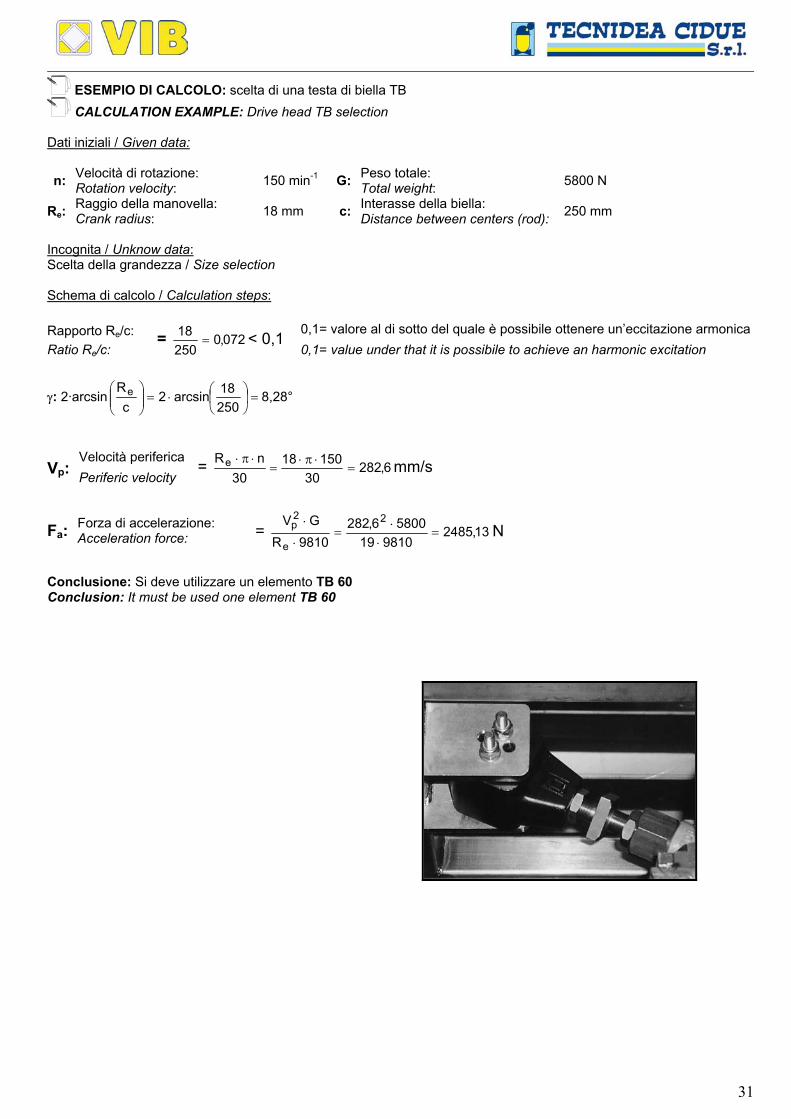
ESEMPIO DI CALCOLO: scelta di una testa di biella TB CALCULATION EXAMPLE: Drive head TB selection
Dati iniziali / Given data:
n: Velocità di rotazione: Rotation velocity: 150 min-1 G: Peso totale:
Total weight: 5800 N
Re: Raggio della manovella: Crank radius: 18 mm c: Interasse della biella:
Distance between centers (rod): 250 mm
Incognita / Unknow data: Scelta della grandezza / Size selection Schema di calcolo / Calculation steps: Rapporto Re/c: 0,1= valore al di sotto del quale è possibile ottenere un’eccitazione armonica Ratio Re/c:
= 072,025018
= < 0,1 0,1= value under that it is possibile to achieve an harmonic excitation
γ: 2·arcsin =
⋅=
25018arcsin2
cRe 8,28°
Velocità periferica Vp: Periferic velocity
= 6,28230
1501830
nRe =⋅π⋅
=⋅π⋅ mm/s
Forza di accelerazione: Fa: Acceleration force: = 13,2485981019
58006,2829810R
GV 2
e
2p =
⋅⋅
=⋅
⋅N
Conclusione: Si deve utilizzare un elemento TB 60 Conclusion: It must be used one element TB 60

32
Elementi Oscillanti VIB Tipo: TP-S e TP-SR / Elastic Components VIB Type: TP-S and TP-SR
L
F
M
A
E
RL1
II
L
F
S S
Q
Q
n
Dm
Ed
A
C
E
F
I
L
L1
M
R
S Tipo Type Cod. N°
Peso Weight in kg
Tipo Type Cod. N°
TP-S 20 RE020622 96 1150 17 4,8 50 7 25 4 100 50 56 70 35 20 0,58 TP-SR 20 RE020642TP-S 30 RE020624 197 1150 21 10,0 60 9,5 35 5 120 62 68 85 40 20 0,76 TP-SR 30 RE020644TP-S 40 RE020626 385 750 28 11,2 80 11,5 45 5 160 73 80 110 60 40 1,75 TP-SR 40 RE020646TP-S 50 RE020628 765 750 35 18,3 100 14 60 6 200 95 104 140 70 50 3,72 TP-SR 50 RE020648TP-S 60 RE020630 1510 750 35 31,8 130 18 70 8 200 120 132 180 80 40 5,57 TP-SR 60 RE020650TP-S 70 RE020632 2370 560 44 35,2 140 18 80 10 250 145 160 190 90 50 8,32 TP-SR 70 RE020652
Q: Carico max in N per sospensione / Max loading in N per rocker suspension
Velocità max di rotazione dell’eccentrico in min-1 per l’angolo max ≮10° con variazione ≮±5° dalla posizione 0 n: Max crank rotation velocity in min-1 at the max angle ≮10° from 0 ≮ ±5°
Dm: Estensione max in mm / Max amplitude given in mm
Elasticità dinamica in N/mm per ≮±5°, nel campo di frequenze da 300 a 600 min-1 Ed:
Dynamic spring value in Nm/° at per ≮ ±5°, in frequency range 300-600 min-1
Lf
Re 3
1
G
B
90°
2
CaricoLoading
Verso di avanzamentoFeed direction
Discharge
Legenda / Key:
1: Grondaia di scorrimento / Sliding chute 2: Sospensione VIB tipo TP-S / TP-S suspension 3: Testa di biella VIB tipo TB / TB Drive head B: Baricentro / Centre of gravity G: Peso Totale / Total weight I: Interasse / Distance between centres Lf: Lunghezza minima del tratto filettato (1.5-2 S) / Min Screwed-in lenght (1.5-2 S) Re: Raggio della manovella / Crank radium S: Diametro filettato testa di biella VIB tipo TB / Threaded diameter inside type TB α: Angolo di montaggio da 20° a 30° / Rocker angle from 20° to 30° β: Angolo di lavoro / Working angle γ: Angolo di oscillazione manovella / Oscillating crank angle
MATERIALI La carpenteria esterna, i quadri interni e le flange sono in acciaio. TRATTAMENTI La carpenteria esterna, i quadri interni e le flange sono verniciate a forno. IMPIEGO Il componente oscillante TP-S è principalmente utilizzato per la realizzazione di sospensioni con interesse non variabile nei trasportatori e vagli vibranti ad azionamento biella/manovella.
MATERIALS The external structure, the inner square and the fixation flange are made of steel. TREATMENTS The external structure, the inner square and the fixation flange are oven-painted. DUTY TP-S oscillating component is generally used to realize oscillating rockers with not adjustable axle base in conveyors or screens actuated by connecting a rod/crank device.
Typ / Type TP-S Typ / Type TP-SR

33
Elementi Oscillanti VIB Tipo: TP-F / Elastic Components VIB Type: TP-F
Q
E
L1
B
R IEL
S
Q
n
Dm
Ed
B
E
I
L
L1
R
S Tipo Type Cod. N°
Peso Weight in kg
TP-F 20 RE020662 96 1150 17 4,8 10 +0,40+0,20 2,5 100 40 45 35 20 0,58
TP-F 30 RE020664 197 1150 21 10,0 13 +0,00+0,20 2,5 120 50 55 40 20 0,76
TP-F 40 RE020666 385 750 28 11,2 16 +0,50+0,30 2,5 160 60 65 60 40 1,75
TP-F 50 RE020668 765 750 35 18,3 20 +0,50+0,20 5 200 80 90 70 50 3,72
TP-F 60 RE020670 1510 750 35 31,8 24 +0,50+0,20 5 200 100 110 80 40 5,57
TP-F 70 RE020672 2370 560 44 35,2 30 +0,50+0,20 5 250 120 130 90 50 6,50
Q: Carico max in N per sospensione / Max loading in N per rocker suspension
Velocità max di rotazione dell’eccentrico in min-1 per l’angolo max ≮10° con variazione ≮±5° dalla posizione 0 n: Max crank rotation velocity in min-1 at the max angle ≮10° from 0 ≮ ±5°
Dm: Estensione max in mm / Max amplitude given in mm
Elasticità dinamica in N/mm per ≮±5°, nel campo di frequenze da 300 a 600 min-1 Ed:
Dynamic spring value in Nm/° at per ≮ ±5°, in frequency range 300-600 min-1
Re
Lf
3
1
G
B
I
290°
Verso di avanzamentoFeed directionCarico
Loading
DischargeScarico
Legenda / Key: 1: Grondaia di scorrimento / Sliding chute 2: Sospensione VIB tipo TP-F / TP-F suspension 3: Testa di biella VIB tipo TB / TB Drive head B: Baricentro / Centre of gravity G: Peso Totale / Total weight I: Interasse / Distance between centres Lf: Lunghezza minima del tratto filettato (1.5-2 S) Min Screwed-in lenght (1.5-2 S) Re: Raggio della manovella / Crank radium S: Diametro filettato testa di biella VIB tipo TB Threaded diameter inside type TB α: Angolo di montaggio da 20° a 30° / Rocker angle from 20° to 30° β: Angolo di lavoro / Working angle γ: Angolo di oscillazione manovella / Oscillating crank angle
MATERIALI La carpenteria esterna è in acciaio mentre i quadri interni sono un profilato di alluminio. TRATTAMENTI La carpenteria esterna è verniciata a forno mentre i quadri interni sono ricoperti con una verniciatura RAL. IMPIEGO Il componente oscillante TP-F è principalmente utilizzato per la realizzazione di sospensioni con interesse non variabile nei trasportatori e vagli vibranti ad azionamento biella/manovella.
MATERIALS The external structure is made of steel while the inner squares are made of light alloy profile. TREATMENTS The external structure is oven-painted while the inner squares are covered with a RAL varnish. DUTY TP-F Oscillating component is particularly used to realize suspension with not adjustable axle base or screen rockers actuated by a connecting rod/crank device.
34
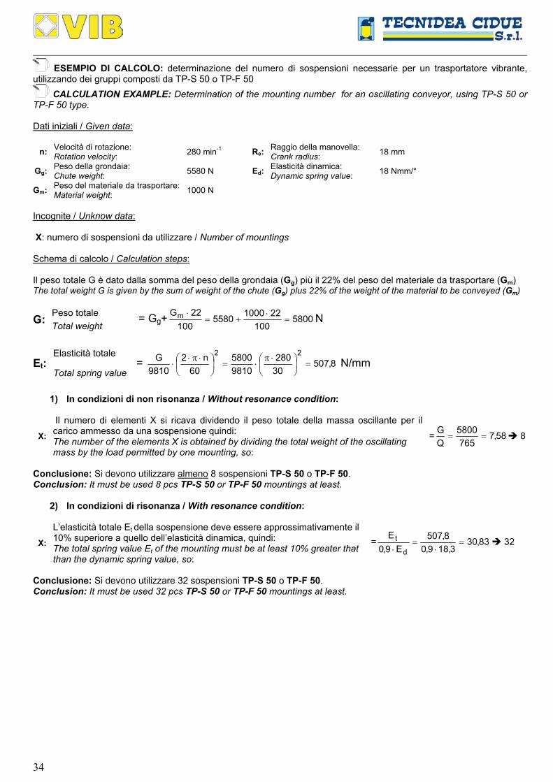
ESEMPIO DI CALCOLO: determinazione del numero di sospensioni necessarie per un trasportatore vibrante, utilizzando dei gruppi composti da TP-S 50 o TP-F 50
CALCULATION EXAMPLE: Determination of the mounting number for an oscillating conveyor, using TP-S 50 or TP-F 50 type. Dati iniziali / Given data:
n: Velocità di rotazione: Rotation velocity: 280 min-1 Re: Raggio della manovella:
Crank radius: 18 mm
Gg: Peso della grondaia: Chute weight: 5580 N Ed: Elasticità dinamica:
Dynamic spring value: 18 Nmm/°
Gm: Peso del materiale da trasportare: Material weight: 1000 N
Incognite / Unknow data: X: numero di sospensioni da utilizzare / Number of mountings Schema di calcolo / Calculation steps: Il peso totale G è dato dalla somma del peso della grondaia (Gg) più il 22% del peso del materiale da trasportare (Gm) The total weight G is given by the sum of weight of the chute (Gg) plus 22% of the weight of the material to be conveyed (Gm)
Peso totale G: Total weight = Gg+ 5800
1002210005580
10022Gm =
⋅+=
⋅ N
Elasticità totale
Et: Total spring value
= 8,50730280
98105800
60n2
9810G 22
=
⋅π⋅=
⋅π⋅⋅ N/mm
1) In condizioni di non risonanza / Without resonance condition:
X:
Il numero di elementi X si ricava dividendo il peso totale della massa oscillante per il carico ammesso da una sospensione quindi: The number of the elements X is obtained by dividing the total weight of the oscillating mass by the load permitted by one mounting, so:
= 58,7765
5800QG
== 8
Conclusione: Si devono utilizzare almeno 8 sospensioni TP-S 50 o TP-F 50. Conclusion: It must be used 8 pcs TP-S 50 or TP-F 50 mountings at least.
2) In condizioni di risonanza / With resonance condition:
X:
L’elasticità totale Et della sospensione deve essere approssimativamente il 10% superiore a quello dell’elasticità dinamica, quindi: The total spring value Et of the mounting must be at least 10% greater that than the dynamic spring value, so:
= 83,303,189,0
8,507E9,0
E
d
t =⋅
=⋅
32
Conclusione: Si devono utilizzare 32 sospensioni TP-S 50 o TP-F 50. Conclusion: It must be used 32 pcs TP-S 50 or TP-F 50 mountings at least.
35
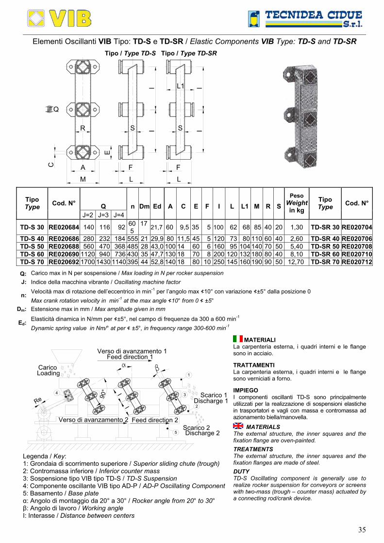
Elementi Oscillanti VIB Tipo: TD-S e TD-SR / Elastic Components VIB Type: TD-S and TD-SR
Tipo / Type TD-S Tipo / Type TD-SR
L
F
R
A
M
E
I
F
L
S S
L1I
C
II
Q
Q
n
Dm
Ed
A
C
E
F
I
L
L1
M
R
S Tipo Type Cod. N°
J=2 J=3 J=4
Peso Weight in kg
Tipo Type Cod. N°
TD-S 30 RE020684 140 116 92 605
17 21,7 60 9,5 35 5 100 62 68 85 40 20 1,30 TD-SR 30 RE020704
TD-S 40 RE020686 280 232 184 555 21 29,9 80 11,5 45 5 120 73 80 110 60 40 2,60 TD-SR 40 RE020706TD-S 50 RE020688 560 470 368 485 28 43,0 100 14 60 6 160 95 104 140 70 50 5,40 TD-SR 50 RE020708TD-S 60 RE020690 1120 940 736 430 35 47,7 130 18 70 8 200 120 132 180 80 40 8,10 TD-SR 60 RE020710TD-S 70 RE020692 1700 1430 1140 395 44 52,8 140 18 80 10 250 145 160 190 90 50 12,70 TD-SR 70 RE020712
Q: Carico max in N per sospensione / Max loading in N per rocker suspension J: Indice della macchina vibrante / Oscillating machine factor
Velocità max di rotazione dell’eccentrico in min-1 per l’angolo max ≮10° con variazione ≮±5° dalla posizione 0 n: Max crank rotation velocity in min-1 at the max angle ≮10° from 0 ≮ ±5°
Dm: Estensione max in mm / Max amplitude given in mm
Elasticità dinamica in N/mm per ≮±5°, nel campo di frequenze da 300 a 600 min-1 Ed:
Dynamic spring value in Nm/° at per ≮ ±5°, in frequency range 300-600 min-1
90°
Re
Verso di avanzamento 1
4
I
5
2
I 3
1
Verso di avanzamento 2
Carico
Scarico 1
Scarico 2
Loading
Feed direction 1
Feed direction 2
Discharge 1
Discharge 2
Legenda / Key: 1: Grondaia di scorrimento superiore / Superior sliding chute (trough) 2: Contromassa inferiore / Inferior counter mass 3: Sospensione tipo VIB tipo TD-S / TD-S Suspension 4: Componente oscillante VIB tipo AD-P / AD-P Oscillating Component 5: Basamento / Base plate α: Angolo di montaggio da 20° a 30° / Rocker angle from 20° to 30° β: Angolo di lavoro / Working angle I: Interasse / Distance between centers
MATERIALI La carpenteria esterna, i quadri interni e le flange sono in acciaio. TRATTAMENTI La carpenteria esterna, i quadri interni e le flange sono verniciati a forno. IMPIEGO I componenti oscillanti TD-S sono principalmente utilizzati per la realizzazione di sospensioni elastiche in trasportatori e vagli con massa e contromassa ad azionamento biella/manovella.
MATERIALS The external structure, the inner squares and the fixation flange are oven-painted.
TREATMENTS The external structure, the inner squares and the fixation flanges are made of steel.
DUTY TD-S Oscillating component is generally use to realize rocker suspension for conveyors or screens with two-mass (trough – counter mass) actuated by a connecting rod/crank device.

36
Elementi Oscillanti VIB Tipo: TD-F / Elastic Components VIB Type: TD-F
L1
E LB
R
Q
E
S II
Q
n
Dm
Ed
B
E
I
L
L1
R
S Tipo Type Cod. N°
J=2 J=3 J=4
Peso Weight in kg
TD-F 30 RE020724 140 116 92 605 17 21,7 12,5 +0,20+0,00 2,5 100 50 55 40 20 0,88
TD-F 40 RE020726 280 232 184 555 21 29,9 16 +0,25+0,00 2,5 120 60 65 60 40 1,95
TD-F 50 RE020728 560 470 368 485 28 43,0 20 +0,25+0,00 5 160 80 90 70 50 4,02
TD-F 60 RE020730 1120 940 736 430 35 47,7 24 +0,25+0,00 5 200 100 110 80 40 6,52
Q: Carico max in N per sospensione / Max loading in N per rocker suspension J: Indice della macchina vibrante / Oscillating machine factor
Velocità max di rotazione dell’eccentrico in min-1 per l’angolo max ≮10° con variazione ≮±5° dalla posizione 0 n: Max crank rotation velocity in min-1 at the max angle ≮10° from 0 ≮ ±5°
Dm: Estensione max in mm / Max amplitude given in mm
Elasticità dinamica in N/mm per ≮±5°, nel campo di frequenze da 300 a 600 min-1 Ed:
Dynamic spring value in Nm/° at per ≮ ±5°, in frequency range 300-600 min-1
90°
Re4
I
5
2
I 3
1LoadingCarico
Feed direction 1Verso di avanzamento 1
Discharge 2Scarico 2
Discharge 1Scarico 1
Feed direction 2Verso di avanzamento 2
Legenda / Key: 1: Grondaia di scorrimento superiore / Superior sliding chute (trough) 2: Contromassa inferiore / Inferior counter mass 3: Sospensione tipo VIB tipo TD-F / TD-F Suspension 4: Componente oscillante VIB tipo AD-P / AD-P Oscillating component 5: Basamento / Base plate α: Angolo di montaggio da 20° a 30° / Rocker angle from 20° to 30° β: Angolo di lavoro / Working angle I: Interasse / Distance between centers
MATERIALI La carpenteria esterna è in acciaio mentre il quadro interno è un profilato di alluminio. TRATTAMENTI La carpenteria esterna è verniciata a forno mentre i quadri interni sono ricoperti con una verniciatura RAL. IMPIEGO I componenti oscillanti TD-F sono principalmente utilizzati per la realizzazione di sospensioni elastiche in trasportatori e vagli con massa e contromassa ad azionamento biella/manovella.
MATERIALS The external structure is made of steel while the inner squares are made of light alloy profile. TREATMENTS The external structure is oven-painted, while the inner squares are covered with a RAL varnish. DUTY TD-F Oscillating component is generally use to realize rocker suspensions for conveyors or screens with two-mass (trough – counter mass) actuated by a connecting rod/crank device.

37
ESEMPIO DI CALCOLO: determinazione del numero di sospensioni necessarie per un trasportatore vibrante, utilizzando dei gruppi composti da TD-S 40 o TD-F 40
CALCULATION EXAMPLE: Determination of the mounting number for an oscillating conveyor using TD-S 40 or TD-F 40 type Dati iniziali / Given data:
n: Velocità di rotazione: Rotation velocity: 385 min-1 Re:
Raggio della manovella: Crank radius: 18 mm
Gg: Peso della grondaia: Chute weight: 1734 N Ed: Elasticità dinamica:
Dynamic spring value: 29,9 Nmm/°
Gm: Peso del materiale da trasportare: Material weight: 300 N
Incognite / Unknow data: X: numero di sospensioni da utilizzare / Number of mountings Schema di calcolo / Calculation steps:
Indice della macchina vibrante
J: Oscillating machine factor = 0,39810
1830385
9810
Re60
n2 22
=⋅
⋅π
=⋅
⋅π⋅
Il peso totale G è dato dalla somma del peso della grondaia (Gg) più il 22% del peso del materiale da trasportare (Gm) The total weight G is given by the sum of weight of the chute (Gg) plus 22% of the weight of the material to be conveyed (Gm)
Peso totale G:
Total weight = Gg+ 1800
1002210001734
10022Gm =
⋅+=
⋅N
Elasticità totale
Et: Total spring value = 29830385
98101800
60n2
9810G 22
=
⋅π⋅=
⋅π⋅⋅ N/mm
1) In condizioni di non risonanza / Without resonance condition:
X: Il numero di elementi X si ricava dividendo il peso totale della massa oscillante per il carico ammesso da una sospensione quindi: The number of the elements X is obtained by dividing the total weight of the oscillating mass by the load permitted by one mounting, so:
= 43,6280
1800QG
== 8
Conclusione: Si devono utilizzare almeno 8 sospensioni TD-S 40 o TD-F 40. Conclusion: It must be used 8 pcs TD-S 40 or TD-F 40 mountings at least.
2) In condizioni di risonanza / With resonance condition:
X: L’elasticità totale Et della sospensione deve essere approssimativamente il 10% superiore a quello dell’elasticità dinamica, quindi: The total spring value Et of the mounting must be at least 10% greater that than the dynamic spring value, so:
= 07,119,299,0
298E9,0
E
d
t =⋅
=⋅
12
Conclusione: Si devono utilizzare 12 sospensioni TD-S 40 o TD-F 40. Conclusion: It must be used 12 pcs TD-S 40 or TD-F 40 mountings at least.

38
Elementi Oscillanti VIB Tipo: AD-P (con funzione di testa di biella) Oscillating mounting VIB Type: AD-P (as Drive Head)
A
G
HH
D
C
L1
LE E
0
F
B
F
40
R180
D
solo AD-P 60 only AD-P 60
TAGLIA 40,50,60 / SIZE 40,50,60
+0,50-0,00
CCCCCCCCCCCCCCCCCCCCCCCCCCCCCCCCCCC
L
L1
EE
D
G
H C H
A
0
CCCCCCCCCCCCCCCCCCCCCCCCCCCCCCC
Ø12
.5
B
30
4030
F
B
F (AD-P 70x200) (AD-P 70x120) Ø20
TAGLIA 70 / SIZE 70
Ed
A
B
C
D
E
F
G
H
L
L1
+0,0 -0,3
Tipo Type Typ
Cod. N°
Peso Weightin kg
AD-P 40 x 60 RE020326 154 27 8 +0,5 +0,0 44 45 ±0,15 2,5 20 ±0,4 89 +0,2
+0,0 22,5 60 65 0,54 AD-P 50 x 80 RE020331 202 38 10 +0,5
+0,0 60 68 ±0,2 2,5 25 ±0,4 120 +0,3+0,0 30 80 90 1,25
AD-P 60 x 80 RE020335 212 45 12 +0,5 +0,0 73 82 ±0,2 5 35 ±0,5 145 +0,4
+0,0 36 80 90 2,00 AD-P 60 x 100 RE020336 250 45 12 +0,5
+0,0 73 82 ±0,2 5 35 ±0,5 145 +0,4+0,0 36 100 110 2,21
AD-P 70 x 120 RE020340 384 50 M12 78 90 ±0,2 5 40 ±0,5 156 +0,4+0,0 39 120 130 5,95
AD-P 70 x 200 RE020341 576 50 M12 78 90 ±0,2 5 40 ±0,5 156 +0,4+0,0 39 200 210 9,82
Elasticità dinamica in N/mm per ≮±5°, nel campo di frequenze da 300 a 600 min-1 Ed:
Dynamic spring value in Nm/° at per ≮ ±5°, in frequency range 300-600 min-1
IRe 90°4 I
5
3
2
1
Feed direction 1Verso di avanzamento 1
Feed direction 2Verso di avanzamento 2
Legenda / Key: 1: Grondaia di scorrimento superiore Superior sliding chute (trough) 2: Contromassa inferiore / Inferior counter mass 3: Sospensione tipo VIB tipo TD-S / TD-S Suspension 4: Componente oscillante VIB tipo AD-P AD-P Oscillating component 5: Basamento / Base plate α: Angolo di montaggio da 20° a 30° Rocker angle from 20° to 30° β: Angolo di lavoro / Working angle I: Interasse / Distance between centers
MATERIALI Dalla grandezza 40 alla 60 il corpo esterno e i quadri interni sono profilati in alluminio. Nella grandezza 70 il corpo esterno è in acciaio mentre i quadri interni sono profilati di alluminio.
TRATTAMENTI Il corpo esterno è verniciato a forno mentre i quadri interni sono ricoperti con una vernice RAL.
IMPIEGO Il componente oscillante AD-P con funzione di testa di biella elastica oscillante è generalmente utilizzata come cerniera elastica per trasferire il movimento al canale vibrante. Questo elemento oscillante AD-P con funzione di testa di biella può essere utilizzato solamente in trasportatori oscillanti in condizione di risonanza. L’angolo di oscillazione massimo totale della manovella deve essere γ<10° con variazione ≮±5° dalla posizione 0.
MATERIALS From size 40 to 60 external boy and inner square are made out of light alloy profile. For size 70 the external body is made of steel while the inner squares are made of alloy profiles.
TREATMENTS The external body is oven-painted while the inner tube is covered with a RAL varnish. DUTY AD-P Oscillating component as drive head can be used only in oscillating conveyor as elastic hinge to transfer the movement in oscillating trough. AD-P Oscillating component as drive head can be used only in shaker conveyors with resonance condition. The maximum angle of the total oscillating angle must not exceed γ<10° from 0 ≮ ±5°

39
ESEMPIO DI CALCOLO: scelta di una testa di biella AD-P CALCULATION EXAMPLE: Drive head AD-P selection
Dati iniziali / Given data:
n: Velocità di rotazione: Rotation velocity: 385 min-1 Gg: Peso della grondaia:
Chute weight: 1734 N
Re: Raggio della manovella: Crank radius: 18 mm Gm: Peso del materiale da trasportare:
Weight material: 300 N
Incognite / Unknow data: Scelta della grandezza / Size selection Schema di calcolo / Calculation steps:
Indice della macchina vibrante J: Oscillating machine factor = 0,3
9810
1830385
9810
Re60
n2 22
=⋅
⋅π
=⋅
⋅π⋅
Il peso totale G è dato dalla somma del peso della grondaia (Gg) più il 22% del peso del materiale da trasportare (Gm) The total weight G is given by the sum of weight of the chute (Gg) plus 22% of the weight of the material to be conveyed (Gm)
Peso totale G:
Total weight = Gg+ 1800
1002210001734
10022Gm =
⋅+=
⋅N
Elasticità totale
Et: Total spring value = 29830385
98101800
60n2
9810G 22
=
⋅π⋅=
⋅π⋅⋅ N/mm
Conclusione: Si deve utilizzare un elemento AD-P 70x120 Conclusion: It must be used one piece AD-P 70x120
40
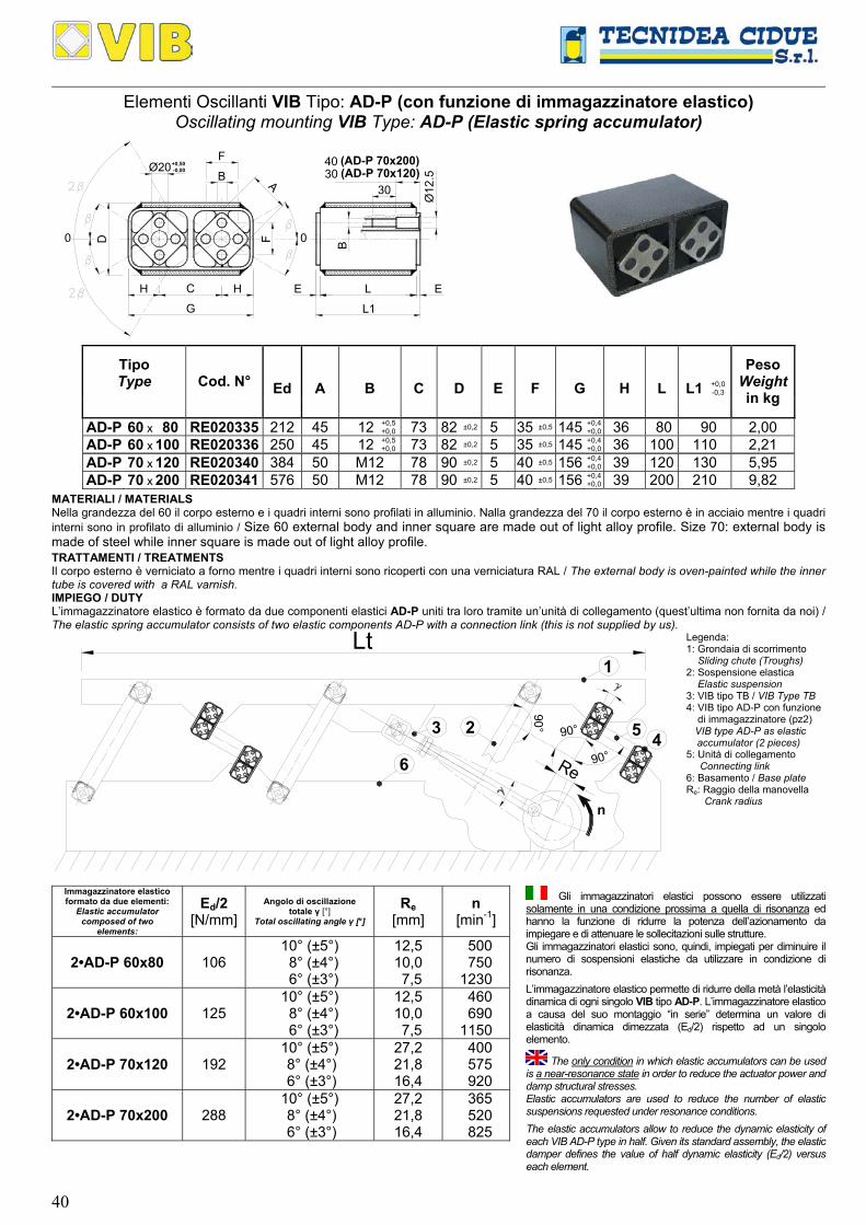
Elementi Oscillanti VIB Tipo: AD-P (con funzione di immagazzinatore elastico) Oscillating mounting VIB Type: AD-P (Elastic spring accumulator)
+0,50-0,00
CCCCCCCCCCCCCCCCCCCCCCCCCCCCCCCCCCC
L
L1
EE
D
G
H C H
A
0
CCCCCCCCCCCCCCCCCCCCCCCCCCCCCCC
Ø12
.5
B
30
4030
F
B
F (AD-P 70x200) (AD-P 70x120) Ø20
Ed
A
B
C
D
E
F
G
H
L
L1
+0,0 -0,3
Tipo Type
Cod. N°
Peso Weightin kg
AD-P 60 x 80 RE020335 212 45 12 +0,5 +0,0 73 82 ±0,2 5 35 ±0,5 145 +0,4
+0,0 36 80 90 2,00 AD-P 60 x 100 RE020336 250 45 12 +0,5
+0,0 73 82 ±0,2 5 35 ±0,5 145 +0,4+0,0 36 100 110 2,21
AD-P 70 x 120 RE020340 384 50 M12 78 90 ±0,2 5 40 ±0,5 156 +0,4+0,0 39 120 130 5,95
AD-P 70 x 200 RE020341 576 50 M12 78 90 ±0,2 5 40 ±0,5 156 +0,4+0,0 39 200 210 9,82
MATERIALI / MATERIALS Nella grandezza del 60 il corpo esterno e i quadri interni sono profilati in alluminio. Nalla grandezza del 70 il corpo esterno è in acciaio mentre i quadri interni sono in profilato di alluminio / Size 60 external body and inner square are made out of light alloy profile. Size 70: external body is made of steel while inner square is made out of light alloy profile.
TRATTAMENTI / TREATMENTS Il corpo esterno è verniciato a forno mentre i quadri interni sono ricoperti con una verniciatura RAL / The external body is oven-painted while the inner tube is covered with a RAL varnish. IMPIEGO / DUTY L’immagazzinatore elastico è formato da due componenti elastici AD-P uniti tra loro tramite un’unità di collegamento (quest’ultima non fornita da noi) / The elastic spring accumulator consists of two elastic components AD-P with a connection link (this is not supplied by us).
90°
90°
1
23
6 90°Re
n
45
Lt
Legenda: 1: Grondaia di scorrimento IIIISliding chute (Troughs) 2: Sospensione elastica IIIIElastic suspension 3: VIB tipo TB / VIB Type TB 4: VIB tipo AD-P con funzione iiiiidi immagazzinatore (pz2) VIB type AD-P as elastic spaccumulator (2 pieces) 5: Unità di collegamento iiiiiiConnecting link 6: Basamento / Base plate Re: Raggio della manovella iiiiiiiiCrank radius
Immagazzinatore elastico formato da due elementi:
Elastic accumulator composed of two
elements:
Ed/2 [N/mm]
Angolo di oscillazione totale γ [°]
Total oscillating angle γ [°]
Re [mm]
n [min-1]
2•AD-P 60x80 106 10° (±5°) 8° (±4°) 6° (±3°)
12,5 10,0 7,5
500 750 1230
2•AD-P 60x100 125 10° (±5°) 8° (±4°) 6° (±3°)
12,5 10,0 7,5
460 690 1150
2•AD-P 70x120 192 10° (±5°) 8° (±4°) 6° (±3°)
27,2 21,8 16,4
400 575 920
2•AD-P 70x200 288 10° (±5°) 8° (±4°) 6° (±3°)
27,2 21,8 16,4
365 520 825
Gli immagazzinatori elastici possono essere utilizzati solamente in una condizione prossima a quella di risonanza ed hanno la funzione di ridurre la potenza dell’azionamento da impiegare e di attenuare le sollecitazioni sulle strutture. Gli immagazzinatori elastici sono, quindi, impiegati per diminuire il numero di sospensioni elastiche da utilizzare in condizione di risonanza.
L’immagazzinatore elastico permette di ridurre della metà l’elasticità dinamica di ogni singolo VIB tipo AD-P. L’immagazzinatore elastico a causa del suo montaggio “in serie” determina un valore di elasticità dinamica dimezzata (Ed/2) rispetto ad un singolo elemento.
The only condition in which elastic accumulators can be used is a near-resonance state in order to reduce the actuator power and damp structural stresses. Elastic accumulators are used to reduce the number of elastic suspensions requested under resonance conditions.
The elastic accumulators allow to reduce the dynamic elasticity of each VIB AD-P type in half. Given its standard assembly, the elastic damper defines the value of half dynamic elasticity (Ed/2) versus each element.

41
ESEMPIO DI CALCOLO: scelta di un immagazzinatore elastico AD-P
CALCULATION EXAMPLE: AD-P Elastic accumulator selection Dati iniziali / Given data: Lt:
Lunghezza del trasportatore: Conveyor lenght:: 8 m Gg: Peso della grondaia:
Chute weight:: 3000 N
X: Numero di sospensioni: Number of mountings: 6 (3 per lato / per side) Gm: Peso del materiale da trasportare:
Material weight: 500 N
n: Velocità di rotazione: Rotation velocity: 345 min-1 Re:
Raggio della manovella: Crank radius: 7,5 mm
Incognite / Unknow data:
Q0: Carico per sospensione Load on per suspensions Ed1: Elasticità dinamica totale fornita dalle sospensioni
Elastic spring value given by the suspensions Etot:
Elasticità dinamica totale fornita da tutti i componenti elastici Dynamic spring value given by all the elastic components S: Scorta di elasticità dinamica
Dynamic spring reserve value Ed2:
Elasticità dinamica totale fornita dagli immagazzinatori elastici Dynamic spring value given by the elastic accumulators
Schema di calcolo / Calculation steps:
Indice della macchina vibrante
J: Oscillating machine factor = 0,19810
5,730345
9810
Re60
n2 22
=⋅
⋅π
=⋅
⋅π⋅
Il peso totale G è dato dalla somma del peso della grondaia (Gg) più il 22% del peso del materiale da trasportare (Gm) The total weight G is given by the sum of weight of the chute (Gg) plus 22% of the weight of the material to be conveyed (Gm)
Peso totale G: Total weight = Gg+ 3110100
225003000100
22Gm =⋅
+=⋅
N
Elasticità totale
Et: Total spring value = 4,41330345
98103110
60n2
9810G 22
=
⋅π⋅=
⋅π⋅⋅ N/mm
Q0: La scelta dell’elemento lo si ricava dividendo il peso totale G per il numero di sospensioni X, quindi: The element selection is obtained by dividing the total weight G by the suspensions number, so:
= 3,5186
3110XG
== N
Si devono utilizzare 6 sospensioni TP-F 50 che forniscono un’elasticità dinamica totale Ed1 = 18,3·6 = 109,8 N/mm It must be used 6 pcs TP-F 50 mountings that give a total dynamic spring value Ed1 = 18,3·6 = 109,8 N/mm
Ed2: Prevediamo l’utilizzo di n°3 immagazzinatori elastici, ciascuno formato da 2 componenti elastici AD-P 60x80, che forniscono un valore di elasticità dinamica totale: We can use 3 pieces of spring elastic accumulator, each consisting of 2 elastic components AD-P 60x80 that give a total dynamic spring value:
= 106·3 = 318 N/mm
Etot = Ed1 + Ed2 = 109,8 + 318 = 427,8 N/mm S = Etot – Et = 427,8 – 413,4 = 14,4 N/mm (3,5 %) Il sistema oscillante detiene ancora il 3,5 % di elasticità da utilizzare come riserva per un eventuale sovraccarico. The oscillating system has still 3,5 % of elastic spring value that can be used as reserve for a possible overloading.
42
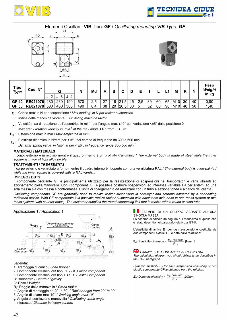
Elementi Oscillanti VIB Tipo: GF / Oscillating mounting VIB Type: GF
CCCCCCCCCCCCCCCCCCCCCCCCCCCCCCC
LE E
IC
M
ØR
S
/ D
/ A
B
Q
N
Md
A
B
C
D
E
I
L
L1
M
R Tipo Type Cod. N°
J=2 J=3 J=4
S
Peso Weight in kg
GF 40 RE021076 280 230 190 570 2,5 27 16 21,5 45 2,5 39 60 65 M10 30 40 0,90 GF 50 RE021078 580 480 380 490 6,4 38 20 26,5 60 5 52 80 90 M10 40 50 1,40
Q: Carico max in N per sospensione / Max loading in N per rocker suspension J: Indice della macchina vibrante / Oscillating machine factor
Velocità max di rotazione dell’eccentrico in min-1 per l’angolo max ≮10° con variazione ≮±5° dalla posizione 0 n: Max crank rotation velocity in min-1 at the max angle ≮10° from 0 ≮ ±5°
Dm: Estensione max in mm / Max amplitude in mm
Elasticità dinamica in N/mm per ≮±5°, nel campo di frequenze da 300 a 600 min-1 Ed:
Dynamic spring value in Nm/° at per ≮ ±5°, in frequency range 300-600 min-1
MATERIALI / MATERIALS Il corpo esterno è in acciaio mentre il quadro interno è un profilato d’alluminio / The external body is made of steel while the inner square is made of light alloy profile.
TRATTAMENTI / TREATMENTS Il corpo esterno è verniciato a forno mentre il quadro interno è ricoperto con una verniciatura RAL / The external body is oven-painted while the inner square is covered with a RAL varnish.
IMPIEGO / DUTY Il componente oscillante GF è principalmente utilizzato per la realizzazione di sospensioni nei trasportatori e vagli vibranti ad azionamento biella/manovella. Con i componenti GF è possibile costruire sospensioni ad interasse variabile sia per sistemi ad una sola massa sia con massa e contromassa. L’unità di collegamento da realizzare con un tubo a sezione tonda è a carico del cliente.
Oscillating components GF are generally used to realize rocker suspension in conveyor and screens actuated by a connecting rod/crank device. With GF components it is possible realize rocker suspension with adjustable axle base in one mass system or two mass system (with counter mass). The customer supplies the round connecting link that is realize with a round section tube.
Applicazione 1 / Application 1:
G
=20°-30°
Re
1
2
3I
90°
B
CC
CC
CC
CC
CC
CC
CC
CC
CC
CC
CC
CC
CC
CC
CC
CC
CC
CC
CC
CC
CC
CC
CC
CC
CC
Verso di avanzamentoFeed direction Carico
Loading
ScaricoDischarge
Legenda: 1: Tramoggia di carico / Load hopper 2: Componente elastico VIB tipo GF / GF Elastic component 3: Componente elastico VIB tipo TB / TB Elastic Component B: Baricentro / Centre of gravity G: Peso / Weight Re: Raggio della manovella / Crank radius α: Angolo di montaggio da 20° a 30° / Rocker angle from 20° to 30° β: Angolo di lavoro max 10° / Working angle max 10° γ: Angolo di oscillazione manovella / Oscillating crank angle I: Interasse / Distance between centers
ESEMPIO DI UN GRUPPO VIBRANTE AD UNA SINGOLA MASSA. Lo schema di calcolo da seguire è il medesimo di quello che è stato descritto nel paragrafo relativo ai BT-F. L’elasticità dinamica Ed per ogni sospensione costituita da due componenti elastici GF è data dalla relazione: Ed: Elasticità dinamica =
π⋅
⋅⋅2I
1000360dM [N/mm]
EXAMPLE OF A ONE-MASS VIBRATING UNIT.
The calculation diagram you should follow is as described in the BT-F paragraph. Dynamic elasticity Ed for each suspension consisting of two elastic components GF is obtained from the relation:
Ed: Dynamic elasticity = π⋅
⋅⋅2I
1000360dM [N/mm]

43
Applicazione 2 / Application 2:
90°
I1 Re3
2
1
= 20°-30°
CC
CCC
CCC
CCC
CCC
CCC
CCC
CCCC
CC
CCC
CCC
CCC
CCC
CCC
CCC
CCC
CCC
CCC
CCC
CCC
CCC
CCC
CCC
CCC
CCC
C
I2
Verso di avanzamento 2
Verso di avanzamento 1Feed direction 1 Carico
Loading
ScaricoDischarge Feed direction 2
ScaricoDischarge
Legenda / Key: 1: Tramoggia di carico / Load hopper 2: Componente elastico VIB tipo GF / GF Elastic component 3: Componente elastico VIB tipo TB / TB Elastic component Re: Raggio della manovella / Crank radius α: Angolo di montaggio da 20° a 30° / Rocker angle from 20° to 30° β: Angolo di lavoro max 10° / Working angle max 10° γ: Angolo di oscillazione manovella / Oscillating crank angle I1: Interasse canale superiore / Superior chute distance between centers I2: Interasse canale inferiore / Inferior chute distance between centers
ESEMPIO DI UN GRUPPO VIBRANTE A DUE MASSE BILANCIATE (medesimo verso di avanzamento sui canali). Lo schema di calcolo da seguire è il medesimo di quello che è stato descritto nel paragrafo relativo ai TD-F. L’elasticità dinamica Ed per ogni sospensione costituita da tre componenti elastici GF è data dalla relazione:
Ed: Elasticità dinamica =
⋅
+π
⋅⋅22
21
22
21d
IIII1000M270
[N/mm]
Con questo sistema è possibile realizzare canali vibranti bilanciati doppi. Il canale inferiore può essere utilizzato sia per raddoppiare la capacità di trasporto del sistema sia per raccogliere il materiale caduto dal canale superiore (setacciatori, calibratori, sfarinatori etc). Il materiale trasportato dal canale superiore e quello dal canale inferiore hanno il medesimo verso di avanzamento.
EXAMPLE OF A TWO-BALANCED-MASS VIBRATING UNIT (same feed directions on the channels). The calculation diagram you should follow is as described in the TD-F paragrap. Dynamic elasticity Ed for each suspension consisting of three elastic components GF is obtained from the relation:
Ed: Dynamic elasticity =
⋅
+π
⋅⋅22
21
22
21d
IIII1000M270
[N/mm]
The above system can be used to make double balanced vibrating channels. The lower channel may be used to double the system conveyance capacity as well as to collect the material falling from the upper channel (sieves, calibrators, dusters, etc.). The feed direction of the material carried by the upper and lower channel is the same.
UNITA’ DI COLLEGAMENTO (a carico del cliente): DIMENSIONI CONSIGLIATE CONNECTING LINK (to be supplied by the customer): RECOMMENDED DIMENSIONS
Tipo Type ØT MS IM
UTILIZZO DUTY
GF 40 30 3 160 Solo applicazione 1 - Only application 1 GF 40 30 4 220 Applicazioni 1 / 2 / 3 - Application 1/2/3 GF 40 30 3 300 Applicazioni 1 / 2 / 3 - Application 1/2/3 GF 50 40 3 200 Solo Applicazione 1 - Only application 1GF 50 40 4 250 Applicazioni 1 / 2 / 3 - Application 1/2/3 GF 50 40 5 300 Applicazioni 1 / 2 / 3 - Application 1/2/3
ØT: Diametro del tubo di connessione / Connecting tube diameter MS: Minimo spessore del tubo / Minimum thickness IM: Interasse massimo / Maximum distance between centers
Applicazione 3 / Application 3:
I1 Re3
2
1
CC
CCC
CC
CCC
CC
CCC
CC
CCC
CC
CCC
I2
90°
CC
CCC
CC
CCC
CC
CCC
CC
CCC
CC
CCC
= 20°-30°
90°
Verso di avanzamento 1Feed direction 1 Carico
Loading
ScaricoDischargeVerso di avanzamento 2
Feed direction 2
Scarico
Legenda / Key: 1: Tramoggia di carico / Load hopper 2: Componente elastico VIB tipo GF / GF Elastic component 3: Componente elastico VIB tipo TB / TB Elastic component Re: Raggio della manovella / Crank radius α: Angolo di montaggio da 20° a 30° / Rocker angle from 20° to 30° β: Angolo di lavoro max 10° / Working angle max 10° γ: Angolo di oscillazione manovella / Oscillating crank angle I1: Interasse canale superiore / Superior chute distance between centers I2: Interasse canale inferiore / Inferior chute distance between centers
ESEMPIO DI UN GRUPPO VIBRANTE A DUE MASSE
BILANCIATE (opposti versi di avanzamento sui canali). Lo schema di calcolo da seguire è il medesimo di quello che stato descritto nel paragrafo relativo ai TD-F. L’elasticità dinamica Ed per ogni sospensione costituita da tre componenti elastici GF è data dalla relazione:
Ed: Elasticità dinamica =
⋅
+π
⋅⋅22
21
22
21d
IIII1000M270
[N/mm]
Con questo sistema è possibile realizzare canali vibranti bilanciati doppi. Il canale inferiore può essere utilizzato sia per raddoppiare la capacità di trasporto del sistema con versi di avanzamento opposti tra la parte superiore e quella inferiore oppure per raccogliere il materiale caduto dal canale superiore (setacciatori, calibratori, sfarinatori etc) e riportarlo all’inizio dell’impianto. Per ottenere i versi di avanzamento opposti su i due canali le sospensioni dovranno essere posizionate perpendicolarmente ai canali e i componenti elastici GF superiori ed inferiori ruotati di 180° rispetto a quello centrale bloccato sul telaio.
EXAMPLE OF A TWO-BALANCED-MASS VIBRATING UNITi (opposite feed directions on the channels). The calculation diagram you should follow is as described in the TD-F paragraph. Dynamic elasticity Ed for each suspension consisting of three elastic components GF is obtained from the relation:
Ed: Dynamic elasticity =
⋅
+π
⋅⋅22
21
22
21d
IIII1000M270
[N/mm]
The above system can be used to make double balanced vibrating channels. The lower channel may be used to double the system conveyance capacity with opposite feed directions of the upper and lower channels as well as to collect the material falling from the upper channel (sieves, calibrators, dusters, etc.) in order to bring it to the starting point of the plant. The two channels opposite feed directions can be obtained by positioning suspensions perpendicular to the channels and by rotating of 180° the upper and lower GF elastic components with respect to the central component which is fixed to the structure.

44
TRASPORTATORI CON AZIONAMENTO: MOTORE VIBRANTE O MASSA ECCENTRICA MOTOR CONVEYORS: VIBRATING MOTOR OR ECCENTRIC MASS
La tecnologia dei prodotti VIB può essere applicata per la realizzazione di sospensioni elastiche per canali vibranti azionati da masse eccentriche (ad esempio motovibratori) in rotazione “montate a bordo”. Per poter realizzare un trasportatore ad oscillazioni in cui le vibrazioni trasportino il materiale con regolarità lungo tutto il piano è indispensabile che il canale vibrante sia il più rigido possibile ed eventualmente nervato nelle direzione di applicazione della forza di azionamento. L’applicazione della forza di eccitazione è generalmente tra i 45°/60° rispetto al piano di avanzamento ed è prodotta da due masse eccentriche rotanti in fase tra loro. Un solo motovibratore, infatti, fornisce delle forze di vibrazione lungo tutte le direzioni sui 360° (fig.1), mentre due motovibratori in fase con verso di rotazione opposto tra loro forniscono una sola vibrazione armonica avente la direzione perpendicolare al piano di applicazione dei due motori (fig.2). La retta d’applicazione della forza d’eccitazione, inoltre, deve cadere nel baricentro del canale. Le velocità di rotazione delle masse devono essere comprese tra i 750 e i 3000 giri/min per non provocare eccessivi squilibri. Le sospensioni elastiche realizzate con la tecnologia VIB, grazie ai loro inserti in gomma naturale, consentono di sviluppare vibrazioni armoniche lungo tutto il piano vibrante negando alle stesse di propagarsi alla struttura fissa dell’impianto. Gli elementi oscillanti VIB consentono di isolare, non essendoci parti metalliche in contatto tra loro, le cariche elettrostatiche che si potrebbero creare per attrito durante il trasporto del materiale.
VIB technology can be applied to produce elastic suspensions for vibrating channels actuated by “on board” eccentric rotating
masses (example: motor vibrators). In order to produce an oscillating conveyor in which vibrations uniformly carry the material along the entire plane, the vibrating channel must be as stiff as possible and, if necessary, with ribs pointing to the direction of application of the actuation force. The application of the excitation force is generally ranging from 45° to 60° compared to the feed plane and is the result of two eccentric masses rotating synchronously. One motor vibrator is enough to supply and spread vibration forces in all directions at 360° (fig. 1) while two timed motor vibrators with opposite rotation direction produce one harmonic vibration only, whose direction is perpendicular to the application plane of the two motors (fig. 2). The straight line of the excitation force must fall in the centre of gravity of the channel. The rotation velocities of the masses must range from 750 and 3000 rounds/min in order to avoid any excessive unbalances. Elastic suspensions obtained with VIB technology, given their inserts of natural rubber, generate harmonic vibrations all along the vibrating plane yet avoiding their propagation to the fix structure of the plant. Because VIB oscillating elements have no metal parts in contact with each other, they can insulate from electrostatic charges, which may be induced by friction while the material is being conveyed.
Fig.1
Fig.2
Sistema con un motovibratore
Questi sistemi possono essere utilizzati negli scivoli di carico o scarico, tramoggie e fondi vibranti, affinché il materiale scorra fluidamente e non si ostacoli accumulandosi durante il movimento. Sono indicati anche per realizzare i vagli inclinati (fig. 3).
System with one motor vibrator These systems can be used for loading and unloading chutes, hoppers and vibrating bottoms, and improve the smooth passage of the material avoiding any accumulations during transportation. They are also ideal to realize tilted screens (fig.3).
G
1
2
Verso di avanzamento20°-30°
Feed direction
CARICOLOADING
SCARICODISCHARGE
3
4
5
Legenda / Key: 1: Tramoggia di carico / Load hopper 2: Piano vibrante / Oscillating feed plane 3: Componente oscillante VIB tipo DE / Elastic components VIB type DE 4: Staffa di supporto VIB tipo SR / Clamp VIB type SR 5: Motovibratore / Vibrating motor Fig 3

45
Sistema con due motovibratori Questo sistema consente di costruire trasportatori, separatori, vagli, calibratori, orientatori, alimentatori, ecc. (fig 4). I motovibratori devono avere il verso di rotazione opposta e devono avere la retta d’applicazione passante per il baricentro della macchina.
System with two motor vibrators This system is used to produce conveyors, separators, screens, calibrators, positioners, feeders, etc. (fig 4). The sense of rotation of motor vibrators must be opposite and their straight line must pass by the centre of gravity of the machine.
45°-60°
G
1
2
3
5 4
CARICOLOADING
SCARICODISCHARGE
Verso di avanzamentoFeed direction
Legenda / Key: 1: Tramoggia di carico / Load hopper 2: Piano vibrante / Oscillating feed plane 3: Componente oscillante VIB tipo DE / Elastic components VIB type DE 4: Staffa di supporto VIB tipo SR / Clamp VIB type SR 5: Motovibratore / Vibrating motor Fig 4
SISTEMI DI CALCOLO E FORMULE (con due motovibratori montati “a bordo”) CALCULATION SYSTEMS AND FORMULA (with two on board vibrating motors on board):
Velocità di rotazione / Rotation velocity PESO SPECIFICO SPECIFIC WEIGHT
GRANULOMETRIA GRANULOMETRY 750 rpm 1000 rpm 1500 rpm 3000 rpm
1 ■ ■ 2 ■ ■ A 3 ■ ■ 1 ■ 2 ■
TRASPORTO LINEARE
RECTILINEAR CONVEYING B
3 ■ ■ Legenda:
- A= alto / high; B= basso / low; - 1= fine / small; 2= media / average; 3= elevata / coarse
Per determinare l’esatta grandezza dell’elemento oscillante VIB è indispensabile conoscere il peso totale della massa oscillante
che è data dalla somma del peso del canale più il peso dei motovibratori e più circa il 20% del peso del materiale trasportato. Una volta determinato questo valore esso va diviso per il numero di sospensioni che si intendono utilizzare. E’ molto importante essere a conoscenza del fatto che per un buon rendimento delle sospensioni VIB è necessario che il carico sia equamente distribuito su ognuna di esse. In genere nei trasportatori vibranti con motovibratori montati “a bordo” essi vengono collocati al di sopra del canale dalla parte dello scarico (fig.5) o al di sotto del canale dalla parte del carico (fig.3), determinando però uno spostamento del baricentro. E’ necessario, pertanto, l’utilizzo di 6 supporti (4 anteriori e 2 posteriori per la configurazione di figura 5 o 4 posteriori e 2 anteriori per la configurazione di figura 6) posizionati in modo che su ognuno di essi gravi all’incirca lo stesso carico.
It is essential to know the total weight of the oscillating mass in order to select the appropriate size of the VIB oscillating element. The oscillating mass is the sum of the weight of the channel added with the weight of the motor vibrators plus approximately 20% of the weight of the carried material. Once this value has been defined, divide it by the number of suspensions that you need to use. You should be well aware that VIB suspensions performance depends on the even distribution of the load on each suspension. Generally, vibrating conveyors with “on board” motor vibrators are mounted over the channel on the unloading section (fig. 5) or under the channel on the loading section (fig. 3). This however causes a shift of the centre of gravity. As a consequence, you should use and position 6 supports (4 in the front and 2 in the rear for the configuration of figure 5, or 4 in the rear and 2 in the front for the configuration of figure 6) ensuring that they are equally charged with the same load
G
Verso di avanzamentoFeed direction
SCARICODISCHARGE
CARICOLOADING45°-60°
Fig.5
G
Verso di avanzamento
SCARICO CARICO
Feed direction
LOADINGDISCHARGE45°-60°
Fig.6

46
Nomenclatura / Nomenclature: Simbolo Symbol
Descrizione Description
Unità di misura / Measure unit
Simbolo Symbol
Descrizione Description
Unità di misura /
Measure unit
Dm Estensione massima Maximum Amplitude [mm] Gv
Peso del motovibratore Motor vibrators weight [N]
fn Frequenza naturale
Own frequency [Hz] J Indice della macchina vibrante Oscillating machine factor
f0
Frequenza ingresso nel sistema
Entrance frequency in the system
[Hz] Mt
Momento statico totale dei motovibratori
Total motor vibrators static moment
[N/mm]
g Accelerazione di gravità Gravitational acceleration [m/s2] n
Velocità di rotazione dei motovibratori
Motor vibrators rotation velocity
[min-1]
G Peso totale Total weight [N] Re
Raggio dell’eccentrico Eccentric radius [mm]
Gg Peso della grondaia
Chute weight [N] Va Velocità di avanzamento
Material feed velocity [m/min]
Gm Peso del materiale Material weight [N] ξ Fattore di isolamento
Isolation factor [%]
Principali formule di calcolo / Main calculation formula:
Formula / Formula Unità di misura
Measure unit Formula / Formula
Unità di misura
Measure unit
G: vmg G210022GG ⋅+⋅+ [N] ξ= 100
1ff
2ff
2
n
0
2
n
0
⋅
−
−
[%]
f0: 60n [Hz] J :
29810
Dn60
2m
2
⋅
⋅
⋅π⋅
Dm : G
81,9M2 t ⋅⋅ [mm]
Grafico velocità teorica / Theoretical velocity graph:
0.4 1 2 3 4 5 6 7 20108 9
42
36
30
24
18
12
6
Estensione massima delle oscillazioni Dm [mm]
n=740
n=2860
n=1460
n=980
3J2J
5J
4J
6J
7J
8J
9J
Theo
retic
al v
eloc
ity V
a [m
/min
]
Dm
Va
Vel
ocità
di a
vanz
amen
to V
a [m
/min
]
Oscillation maximum amplitude Dm [mm]
Questo grafico consente di determinare la velocità di
avanzamento teorica del materiale in un trasportatore con due motovibratori montati a bordo e posizionati a 45° rispetto al piano di scorrimento. La velocità reale di avanzamento Vr dipende però dalla tipologia di prodotto trasportato. La velocità reale Vr è data dalla relazione: Vr = Va · λ Dove λ è il coefficiente di riduzione dovuto alla coesione dipendente dalla tipologia del materiale da trasportare.
This graph can be used to determine the theoretical feed velocity of the material in a conveyor with two on board motor vibrators which are positioned at 45° versus the sliding plane. The real feed velocity Vr depends on the type of product being carried. Real velocity Vr is given by the relation: Vr = Va · λ Where λ is the coefficient of reduction generated by the cohesion which depends on the type of material to be carried.
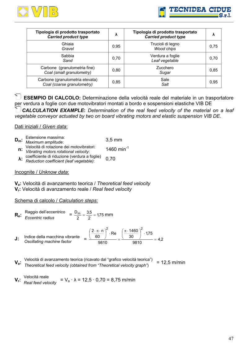
47
Tipologia di prodotto trasportato
Carried product type λ Tipologia di prodotto trasportato Carried product type λ
Ghiaia Gravel 0,95 Trucioli di legno
Wood chips 0,75
Sabbia Sand 0,70 Verdura a foglie
Leaf vegetable 0,70
Carbone (granulometria fine) Coal (small granulometry) 0,80 Zucchero
Sugar 0,85
Carbone (granulometria elevata) Coal (coarse granulometry) 0,85 Sale
Salt 0,95
ESEMPIO DI CALCOLO: Determinazione della velocità reale del materiale in un trasportatore
per verdura a foglie con due motovibratori montati a bordo e sospensioni elastiche VIB DE CALCULATION EXAMPLE: Determination of the real feed velocity of the material on a leaf
vegetable conveyor actuated by two on board vibrating motors and elastic suspension VIB DE. Dati iniziali / Given data: Dm: Estensione massima:
Maximum amplitude: 3,5 mm
n: Velocità di rotazione dei motovibratori: Vibrating motors rotational velocity: 1460 min-1
λ: coefficiente di riduzione (verdura a foglie) Reduction coefficient (leaf vegetable): 0,70
Incognite / Unknow data: Va: Velocità di avanzamento teorica / Theoretical feed velocity Vr: Velocità di avanzamento reale / Real feed velocity Schema di calcolo / Calculation steps:
Raggio dell’eccentrico Re: Eccentric radius = 75,1
25,3
2Dm == mm
Indice della macchina vibrante J: Oscillating machine factor = 2,4
9810
75,1301460
9810
Re60
n2 22
=⋅
⋅π
=⋅
⋅π⋅
Velocità di avanzamento teorica (ricavato dal “grafico velocità teorica”) Va: Theoretical feed velocity (obtained from “Theoretical velocity graph”) = 12,5 m/min
Velocità reale Vr: Real feed velocity = Va · λ = 12,5 · 0,70 = 8,75 m/min
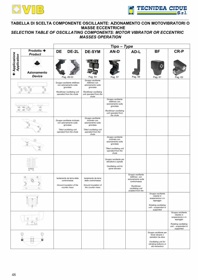
48
TABELLA DI SCELTA COMPONENTE OSCILLANTE: AZIONAMENTO CON MOTOVIBRATORI O MASSE ECCENTRICHE
SELECTION TABLE OF OSCILLATING COMPONENTS: MOTOR VIBRATOR OR ECCENTRIC MASSES OPERATION
Tipo – Type
Prodotto Product
App
licaz
ione
App
licat
ion
Azionamento Device
DE DE-2L
Pag. 49-53
DE-SYM
Pag. 54
AN-D
Pag. 57
AD-L
Pag. 59
BF
Pag. 61
CR-P
Pag. 63
Gruppo oscillante rettilineo con azionamento sulla
grondaia
Rectilinear oscillating unit operated from the chute
Gruppo oscillante rettilineo con
azionamento sulla grondaia
Rectilinear oscillating unit operated from the
chute
Gruppo oscillante rettilineo con
azionamento sulla grondaia
Rectilinear oscillating
unit operated from the chute
Gruppo oscillante inclinato con azionamento sulla
grondaia
Tilted oscillating unit operated from the chute
Gruppo oscillante inclinato con
azionamento sulla grondaia
Tilted oscillating unit
operated from the chute
Gruppo oscillante inclinato con
azionamento sulla grondaia
Tilted oscillating unit operated from the
chute
Gruppo oscillante per elevatore a spirale
Oscillating unit for
spiral elevator
Isolamento da terra della contromassa
Ground insulation of the
counter mass
Isolamento da terra della contromassa
Ground insulation of
the counter mass
Gruppo oscillante rettilineo con
azionamento sulla contromassa
Rectilinear
oscillating unit enabled from the
Gruppo oscillante rotante in
sospensione o in appoggio
Rotating oscillating unit – suspended or
supported
Gruppo oscillante rotante in
sospensione o in appoggio
Rotating oscillating unit – suspended or
supported
Gruppo oscillante per fondi vibranti o
estrattori da silos
Oscillating unit for vibrating bottoms or
silo extractors
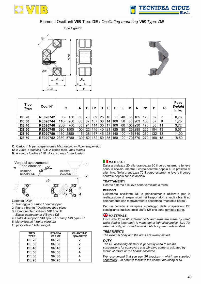
49
Elementi Oscillanti VIB Tipo: DE / Oscillating mounting VIB Type: DE
N-N
1ØR
Tipo Type DE
C-C1
M
A
CCCCCCCCCCCCCCCCCCCCCCCCCCCCCCCCCCC
G
P
L
D
E
CC
CC
CC
CC
CC
CC
CC
CC
CC
CCCCCCCCCCCCCCCCCCCCCCCCCCCCCCC
CC
CC
CC
CC
CC
CC
CC
CC
CC
CC
CC
CC
CC
CC
CC
CC
CC
CC
CC
CC
CC
CC
CC
CC
CC
CC
C
CC
CC
CC
CC
CC
CC
CC
CC
CC
CC
CC
CC
CC
CC
CC
CC
CC
CC
Q
A
C
C1
D
E
G
L
M
N
N1
P
R Tipo Type Cod. N°
Peso Weightin kg
DE 20 RE020742 0- 150 50 70 89 25 10 80 40 65 165 120 52 7 0,76 DE 30 RE020744 116- 280 60 87 107 30 14 100 50 80 203 150 67 9 1,75 DE 40 RE020746 238- 760 80 94 114 35 17 100 60 105 230 170 80 11 3,72 DE 50 RE020748 580- 1500 100 122 146 40 21 125 80 125 295 225 104 13 5,57 DE 60 RE020750 1160- 2880 115 138 167 45 28 140 100 145 340 260 132 13 11,00 DE 70 RE020752 2380- 5780 130 152 182 50 35 150 120 170 370 270 160 18 18,50
Q: Carico in N per sospensione / Max loading in N per suspension C: A vuoto / loadless / C1: A carico max / max loaded N: A vuoto / loadless / N1: A carico max / max loaded
45°-60°
G
1
2
3
5 4
CARICOLOADING
SCARICODISCHARGE
Verso di avanzamentoFeed direction
Legenda / Key: 1: Tramoggia di carico / Load hopper 2: Piano vibrante / Oscillating feed plane 3: Componente oscillante VIB tipo DE Elastic components VIB type DE 4: Staffa di supporto VIB tipo SR / Clamp VIB type SR 5: Motovibratori / Motor vibrators G: peso totale / Total weight
TIPO TYPE
STAFFA CLAMP
QUANTITA’ QUANTITY
DE 20 SR 20 2 DE 30 SR 30 2 DE 40 SR 40 2 DE 50 SR 50 4 DE 60 SR 60 4 DE 70 SR 70 4
MATERIALI Dalla grandezza 20 alla grandezza 60 il corpo esterno e le leve sono in acciaio, mentre il corpo centrale doppio è un profilato di alluminio. Nella grandezza 70 il corpo esterno, le leve e il corpo centrale doppio sono in acciaio.
TRATTAMENTI Il corpo esterno e le leve sono verniciate a forno.
IMPIEGO L’elemento oscillante DE è principalmente utilizzato per la realizzazione di sospensioni nei trasportatori e vagli vibranti ad azionamento con motovibratori o eccentrico “montati a bordo”.
Per un corretto e semplice montaggio delle sospensioni DE consigliamo l’utilizzo delle staffe SR che sono fornite a parte.
MATERIALS From size 20 to 60 external body and arms are made by steel, while double inner body is made out of light alloy profile. Size 70: external body, arms and inner double body are made in steel.
TREATMENTS The external body and the arms are oven-painted.
DUTY The DE oscillating element is generally used to realize suspensions for conveyors and vibrating screens actuated by motor vibrators or “on board” eccentric.
We recommend that you use SR brackets – which are supplied separately – in order to facilitate the correct mounting of DE
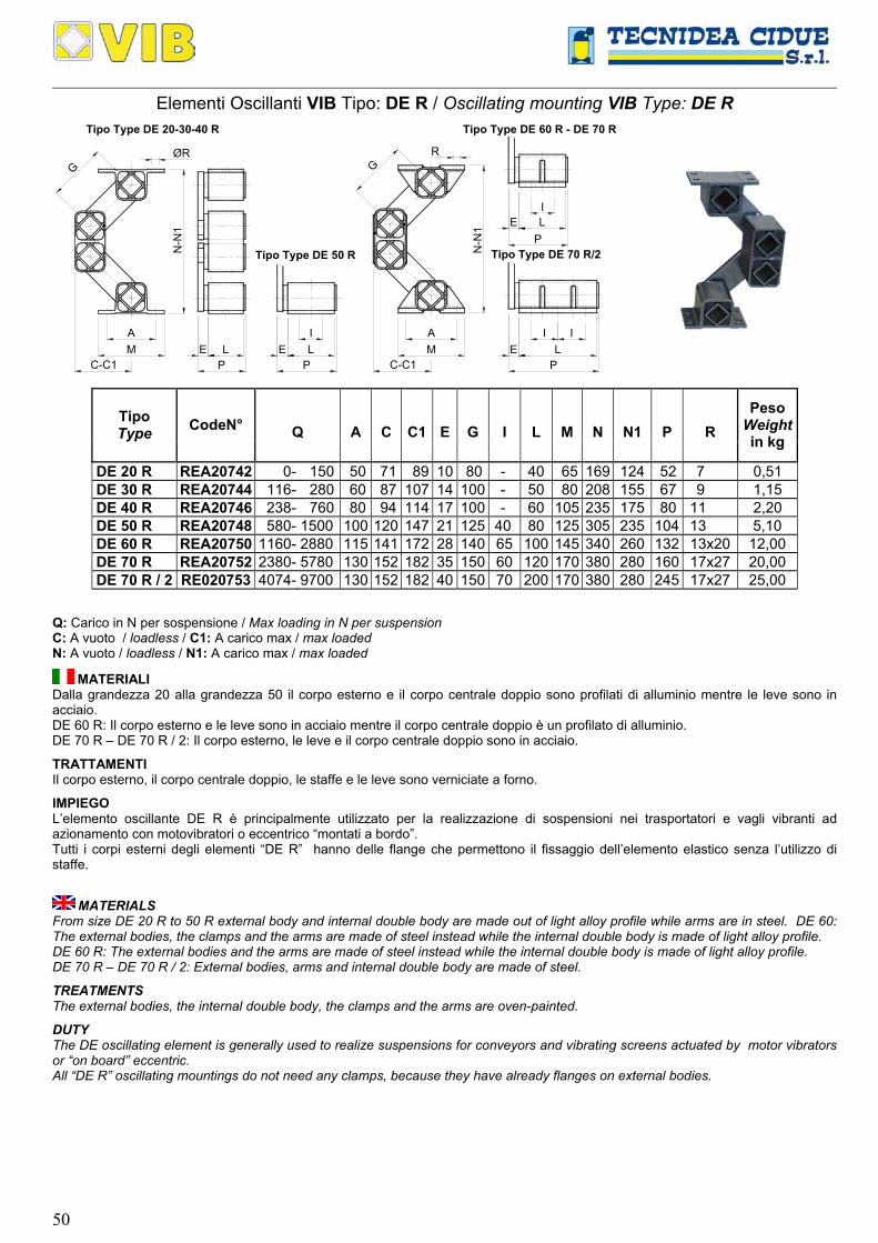
50
Elementi Oscillanti VIB Tipo: DE R / Oscillating mounting VIB Type: DE R
Tipo Type DE 50 R
PL
CC
CC
CC
CC
CC
CC
CC
CC
CC
ØRG
MC-C1
A
CC
CC
CC
CC
CC
CC
CC
CC
CC
N-N
1
PE L
CC
CC
CC
CC
CC
CC
CC
CC
CC
CC
CC
CC
CC
CC
CC
CC
CC
CC
CC
CC
CC
CC
CC
CC
CC
CC
CC
EI
Tipo Type DE 20-30-40 R
CC
CC
CC
CC
CC
CC
CC
CC
CC
CC
RG
E
Tipo Type DE 70 R/2
E
N-N
1
CC
CC
CC
CC
CC
MA
CCCCCCCC
CC
CC
CC
CC
CC
CC
CC
CC
CC
CC
CC
CC
CC
CC
CC
CC
CC
C
CC
CC
CC
CC
CC
CCCCCCCC
CC
CC
CC
CC
CC
CC
CC
CC
CC
CC
CC
CC
CC
CC
CC
CC
CC
CC
CC
CC
CC
CC
CC
CC
CC
CC
CC
CC
CC
CCCCCCCCCC
PL
CCCCCCCCCCCCC
I
CCCCCCCCCCC
I
LP
CC CC
I
CCCCCCCCCCCCC
CC
CC
CC
CC
CC
CC
CC
CC
CC
Tipo Type DE 60 R - DE 70 R
C-C1
Q
A
C
C1
E
G
I
L
M
N
N1
P
R Tipo Type CodeN°
Peso Weightin kg
DE 20 R REA20742 0- 150 50 71 89 10 80 - 40 65 169 124 52 7 0,51 DE 30 R REA20744 116- 280 60 87 107 14 100 - 50 80 208 155 67 9 1,15 DE 40 R REA20746 238- 760 80 94 114 17 100 - 60 105 235 175 80 11 2,20 DE 50 R REA20748 580- 1500 100 120 147 21 125 40 80 125 305 235 104 13 5,10 DE 60 R REA20750 1160- 2880 115 141 172 28 140 65 100 145 340 260 132 13x20 12,00 DE 70 R REA20752 2380- 5780 130 152 182 35 150 60 120 170 380 280 160 17x27 20,00 DE 70 R / 2 RE020753 4074- 9700 130 152 182 40 150 70 200 170 380 280 245 17x27 25,00
Q: Carico in N per sospensione / Max loading in N per suspension C: A vuoto / loadless / C1: A carico max / max loaded N: A vuoto / loadless / N1: A carico max / max loaded
MATERIALI Dalla grandezza 20 alla grandezza 50 il corpo esterno e il corpo centrale doppio sono profilati di alluminio mentre le leve sono in acciaio. DE 60 R: Il corpo esterno e le leve sono in acciaio mentre il corpo centrale doppio è un profilato di alluminio. DE 70 R – DE 70 R / 2: Il corpo esterno, le leve e il corpo centrale doppio sono in acciaio.
TRATTAMENTI Il corpo esterno, il corpo centrale doppio, le staffe e le leve sono verniciate a forno.
IMPIEGO L’elemento oscillante DE R è principalmente utilizzato per la realizzazione di sospensioni nei trasportatori e vagli vibranti ad azionamento con motovibratori o eccentrico “montati a bordo”. Tutti i corpi esterni degli elementi “DE R” hanno delle flange che permettono il fissaggio dell’elemento elastico senza l’utilizzo di staffe.
MATERIALS From size DE 20 R to 50 R external body and internal double body are made out of light alloy profile while arms are in steel. DE 60: The external bodies, the clamps and the arms are made of steel instead while the internal double body is made of light alloy profile. DE 60 R: The external bodies and the arms are made of steel instead while the internal double body is made of light alloy profile. DE 70 R – DE 70 R / 2: External bodies, arms and internal double body are made of steel.
TREATMENTS The external bodies, the internal double body, the clamps and the arms are oven-painted.
DUTY The DE oscillating element is generally used to realize suspensions for conveyors and vibrating screens actuated by motor vibrators or “on board” eccentric. All “DE R” oscillating mountings do not need any clamps, because they have already flanges on external bodies.

51
TABELLA DEI VALORI DI ELASTICITA’ DINAMICA con f=960 min-1 e Dm= 8 mm DYNAMIC SPRING VALUE TABLE at f=960 min-1 and Dm= 8 mm
VERTICALE VERTICAL
ORRIZONTALE HORIZONTAL TIPO
TYPE Ed [N/mm] Ed [N/mm]
DE 20 – DE 20 R 9,6 5,8 DE 30 – DE 30 R 17,3 13,4 DE 40 – DE 40 R 38,4 24,0 DE 50 – DE 50 R 57,6 28,8 DE 60 – DE 60 R 96,0 48,0 DE 70 – DE 70 R 182,4 81,6
DE 70 R / 2 307,2 134,4 f: velocità di rotazione / rotation velocity [min-1]; Dm: Estensione max / Max amplitude [mm]
ESEMPIO DI CALCOLO: Determinazione della corretta grandezza di sospensioni DE e DE R CALCULATION EXAMPLE: Determination of DE and DE R suspension correct size.
Dati iniziali / Given data: X: Numero di sospensioni / Suspension number: 6 Gm: Peso del materiale da trasportare / Material weight: 500 N Gg: Peso della grondaia / Chute weight: 3000 N Gv: Peso di un motovibratore / Motor vibrators weight: 200 N Incognite / Unknow data: Q0: Carico per sospensione / Load capacity per mounting Schema di calcolo / Calculation steps: Il peso totale G è dato dalla somma del peso della grondaia (Gg) più il 22% del peso del materiale da trasportare (Gm) più il peso dei motovibratori. The total weight G is given by the sum of weight of the chute (Gg) plus 22% of the weight of the material to be conveyed (Gm) plus the weight of the motovibrators.
Peso G: Total = Gg+ 35102002
100225003000G2
10022G
vm =⋅+
⋅+=⋅+
⋅ N
Il tipo di sospensione lo si ricava dividendo il peso totale (G) per il numero di sospensioni (X), quindi:
Q0: The suspension type is obtained by dividing the total weight (G) by the number of mountings (X), so:
= 585
63510
XG
== N
Conclusione: Si devono utilizzare 6 sospensioni DE 50 Conclusion: It must be used 6 pcs DE 50 mountings. GRAFICI DI CARICO / LOAD GRAPH
0 20 40 60 80
500
1000
2000
VIB DE 20 (fn: 2,8-4,3)VIB DE 30 (fn: 2,6-3,6)
VIB DE 40 (fn: 2,7-3,7)VIB DE 50 (fn: 2,4-3,0)
c
Q
2500
5000
7500
10000
900 30 60 150
VIB DE 70/2 (fn: 2,1-2,4)
VIB DE 70 (fn: 2,1-2,4)
VIB DE 60 (fn: 2,3-2,8)
c
Q
(Q: Carico verticale di compressione [N]; c: Freccia [mm]; fn: Frequenza propria [Hz]) (Q: Vertical compression load [N]; c: Set [mm]; fn: Own frequency [Hz])
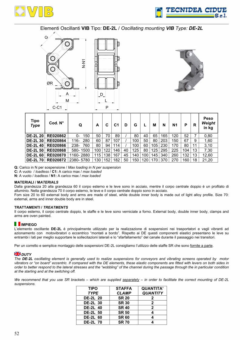
52
Elementi Oscillanti VIB Tipo: DE-2L / Oscillating mounting VIB Type: DE-2L
G
D
P
LC
CC
CC
CC
CC
CC
CC
CC
CC
CC
CC
CC
CC
CC
CC
CC
CC
CC
CC
CC
CC
CC
CC
CC
CC
CC
CC
CC
CC
CC
CC
CC
CC
CC
CC
CC
C
A
M
C-C1
ØRN
-N1
CC
CC
CC
CC
CC
CC
CC
CC
CC
CC
CC
CC
CC
CC
CC
CC
CC
C
CCCCCCCCCCCCCCCCCCCCCCCCCCCCCCC
CC
CC
CC
CC
CC
CC
CC
CC
CC
CC
CC
CC
CC
CC
CC
CC
CC
C
Q
A
C
C1
D
G
L
M
N
N1
P
R Tipo Type Cod. N°
Peso Weight in kg
DE-2L 20 RE020862 0- 150 50 70 89 / 80 40 65 165 120 52 7 0,80 DE-2L 30 RE020864 116- 280 60 87 107 / 100 50 80 203 150 67 9 1,60 DE-2L 40 RE020866 238- 760 80 94 114 / 100 60 105 230 170 80 11 3,10 DE-2L 50 RE020868 580- 1500 100 122 146 40 125 80 125 295 225 104 13 7,30 DE-2L 60 RE020870 1160- 2880 115 138 167 45 140 100 145 340 260 132 13 12,60 DE-2L 70 RE020872 2380- 5780 130 152 182 50 150 120 170 370 270 160 18 21,20
Q: Carico in N per sospensione / Max loading in N per suspension C: A vuoto / loadless / C1: A carico max / max loaded N: A vuoto / loadless / N1: A carico max / max loaded
MATERIALI / MATERIALS Dalla grandezza 20 alla grandezza 60 il corpo esterno e le leve sono in acciaio, mentre il corpo centrale doppio è un profilato di alluminio. Nella grandezza 70 il corpo esterno, le leve e il corpo centrale doppio sono in acciaio. Fom size 20 to 60 external body and arms are made of steel, while double inner body is made out of light alloy profile. Size 70: external, arms and inner double body are in steel. TRATTAMENTI / TREATMENTS Il corpo esterno, il corpo centrale doppio, le staffe e le leve sono verniciate a forno. External body, double inner body, clamps and arms are oven painted.
IMPIEGO L’elemento oscillante DE-2L è principalmente utilizzato per la realizzazione di sospensioni nei trasportatori e vagli vibranti ad azionamento con motovibratori o eccentrico “montati a bordo”. Rispetto ai DE questi componenti elastici presentano le leve su entrambi i lati per meglio supportare le sollecitazioni laterali e lo “sfarfallamento” del canale durante il passaggio nei transitori. Per un corretto e semplice montaggio delle sospensioni DE-2L consigliamo l’utilizzo delle staffe SR che sono fornite a parte.
DUTY The DE-2L oscillating element is generally used to realize suspensions for conveyors and vibrating screens operated by motor vibrators or “on board” eccentric. If compared with the DE elements, these elastic components are fitted with levers on both sides in order to better respond to the lateral stresses and the “wobbling” of the channel during the passage through the in particular condition at the starting and at the switching off. We recommend that you use SR brackets – which are supplied separately – in order to facilitate the correct mounting of DE-2L suspensions.
TIPO TYPE
STAFFA CLAMP
QUANTITA’ QUANTITY
DE-2L 20 SR 20 2 DE-2L 30 SR 30 2 DE-2L 40 SR 40 2 DE-2L 50 SR 50 4 DE-2L 60 SR 60 4 DE-2L 70 SR 70 4

53
Elementi Oscillanti VIB Tipo: DE-2L R / Oscillating mounting VIB Type: DE-2L R
Tipo Type
PL
CC
CC
CC
CC
CC
CC
CC
CC
CC
ØRG
MC-C1
A
CC
CC
CC
CC
CC
CC
CC
CC
CC
N-N
1
PE L
CC
CC
CC
CC
CC
CC
CC
CC
CC
CC
CC
CC
CC
CC
CC
CC
CC
CC
CC
CC
CC
CC
CC
CC
CC
CC
CC
EI
Tipo Type DE-2L 20-30-40 R
CC
CC
CC
CC
CC
CC
CC
CC
CC
CC
RG
E
E
N-N
1
MA
CC
CC
CC
CC
CC
CC
CC
CC
CC
CC
CC
CC
CC
CC
CC
CC
CC
C
CC
CC
CC
CC
CC
CCCCCCCC
CC
CC
CC
CC
CC
CC
CC
CC
CC
CC
CC
CC
CC
CC
CC
CC
CC
CC
CC
CC
CC
CC
CC
CC
CC
CC
CC
CC
CC
CCCCCCCCCC
PL
CCCCCCCCCCCCC
I
CCCCCCCCCCC
I
LP
CC CC
ICCCCCCCCCCCC
CC
CC
CC
CC
C
CC
CC
CC
CC
CC
Tipo Type
C-C1
CC
C
CCCCCCCC
DE-2L 50 R
DE-2L 60 RDE-2L 70 R
Q
A
C
C1
G
L
M
N
N1
P
R Tipo Type Cod.N°
Peso Weight in kg
DE-2L 20 R REA20862 0- 150 50 71 89 80 40 65 169 124 74 7 0,80 DE-2L 30 R REA20864 116- 280 60 87 107 100 50 80 208 155 86 9 1,60 DE-2L 40 R REA20866 238- 760 80 94 114 100 60 105 235 175 100 11 3,10 DE-2L 50 R REA20868 580- 1500 100 120 147 125 80 125 305 235 124 13 7,30 DE-2L 60 R REA20870 1160- 2880 115 141 172 140 100 145 353 273 154 13 14,00 DE-2L 70 R REA20872 2380- 5780 130 152 182 150 120 170 380 280 187 17 22,20
DE-2L 70 R/2 REA20873 4074 9700 130 152 182 150 200 170 380 280 262 17 27,20
Q: Carico in N per sospensione / Max loading in N per suspension C: A vuoto / loadless / C1: A carico max / max loaded N: A vuoto / loadless / N1: A carico max / max loaded
MATERIALI Dalla grandezza 20 alla grandezza 50 il corpo esterno e il corpo centrale doppio sono profilati di alluminio mentre le leve sono in acciaio. DE-2L 60 R: Il corpo esterno e le leve sono in acciaio mentre il corpo centrale doppio è un profilato di alluminio. DE-2L 70 R – DE-2L 70 R / 2: Il corpo esterno, le leve e il corpo centrale doppio sono in acciaio.
TRATTAMENTI Il corpo esterno, il corpo centrale doppio, le staffe e le leve sono verniciate a forno.
MATERIALS From size 20 to 50:external body and inner double body are made out of light alloy profile while arms are made of steel. DE-2L 60R: external body and arms are made of steel while inner double body is made our of light alloy profile. DE-2L 70R – DE-2L 70R/2: external body, arms and double inner body are made of steel.
TREATMENTS The external bodies, the internal double body, and the arms are oven-painted.
IMPIEGO L’elemento oscillante DE-2L R è principalmente utilizzato per la realizzazione di sospensioni nei trasportatori e vagli vibranti ad azionamento con motovibratori o eccentrico “montati a bordo”. Rispetto ai DE questi componenti elastici presentano le leve su entrambi i lati per meglio supportare le sollecitazioni laterali e lo “sfarfallamento” del canale durante il passaggio nei transitori. Tutti i corpi esterni degli elementi “DE-2L R” hanno delle flange che permettono il fissaggio dell’elemento elastico senza l’utilizzo di staffe.
DUTY The DE-2L R oscillating element is generally used to realize suspensions for conveyors and vibrating screens operated by motor vibrators or “on board” eccentric. If compared with the DE elements, these elastic components are fitted with levers on both sides in order to better respond to the lateral stresses and the “wobbling” of the channel during the passage through the in particular condition at the starting and at the switching off. All “DE-2L R” oscillating mountings do not need any clamps, because they have already flanges on external bodies.
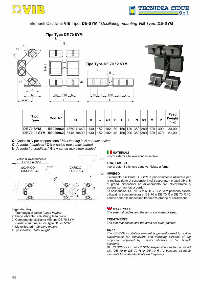
54
Elementi Oscillanti VIB Tipo: DE-SYM / Oscillating mounting VIB Type: DE-SYM
L
CCCCCCCCCCC
CCCCCCCCCCCCCCCCCCCCCCCCCCCCCCC
60
P
N-N
1C
CC
CC
CC
CC
CC
CC
CC
CC
CC
CC
CC
CC
CC
CC
CC
CC
CC
CC
CC
CC
CC
CC
CC
CC
CC
CC
CC
CC
CC
CC
CC
CC
CC
CC
C
A
M
C-C1
CC
CC
CC
CC
CC
CCCCCCCC
CCCCCCCC
CC
CC
CC
CC
CC
120
P
27
L
Tipo Type DE 70 / 2 SYMC
CC
CC
CC
CC
CC
CC
CC
CC
CC
CC
CC
CC
CC
CC
CC
CC
CC
CC
CC
CC
CC
CC
CC
CC
CC
CC
110 60
CCCCCCCCCCCC
CC
CC
CC
CC
CC
CC
CC
CC
CC
CC
CC
CC
CC
CC
CC
CC
CC
CC
27CC
7070
Tipo Type DE 70 SYM
CCCCCCCCCCCCC
CC
CC
CC
CC
CC
CC
CC
CC
CC
CC
CC
CC
CC
CC
CC
CC
CC
CC
CCCCCCCCCCC
CC
CC
CC
CC
CC
CC
CC
CC
CC
CC
CCCCCCCCCCCCCCCCCCCCCCCCCCCCCCCC
E
7070
E
G
17
Q
A
C
C1
E
G
L
N
N1
M
P Tipo Type Cod. N°
Peso Weightin kg
DE 70 SYM RE020960 4850-11640 130 152 182 30 150 120 380 280 170 300 33,00 DE 70 / 2 SYM RE020962 8148-19400 130 152 182 40 150 200 380 280 170 470 51,00
Q: Carico in N per sospensione / Max loading in N per suspension C: A vuoto / loadless / C1: A carico max / max loaded N: A vuoto / unloadless / N1: A carico max / max loaded
45°-60°
G
1
2
3
4
CARICOLOADING
SCARICODISCHARGE
Verso di avanzamentoFeed direction
Legenda / Key: 1: Tramoggia di carico / Load hopper 2: Piano vibrante / Oscillating feed plane 3: Componente oscillante VIB tipo DE 70 SYM Elastic components VIB type DE 70 SYM 4: Motovibratori / Vibrating motors G: peso totale / Total weight
MATERIALI I corpi esterni e le leve sono in acciaio. TRATTAMENTI I corpi esterni e le leve sono verniciate a forno. IMPIEGO L’elemento oscillante DE-SYM è principalmente utilizzato per la realizzazione di sospensioni nei trasportatori e vagli vibranti di grandi dimensioni ad azionamento con motovibratori o eccentrico “montati a bordo”. Le sospensioni DE 70 SYM o DE 70 / 2 SYM possono essere utilizzati in concomitanza ai DE 70 o DE 70 R o DE 70 R / 2 perché hanno le medesime frequenze proprie di oscillazione.
MATERIALS The external bodies and the arms are made of steel. TREATMENTS The external bodies and the arms are oven-painted. DUTY The DE-SYM oscillating element is generally used to realize suspensions for conveyors and vibrating screens of big proportion actuated by motor vibrators or “on board” eccentric. DE 70 SYM or DE 70 / 2 SYM suspension can be combined with DE 70 or DE 70 R or DE 70 R / 2 because all these elements have the identical own frequency.
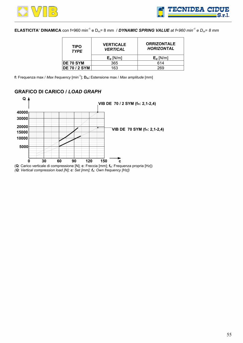
55
ELASTICITA’ DINAMICA con f=960 min-1 e Dm= 8 mm / DYNAMIC SPRING VALUE at f=960 min-1 e Dm= 8 mm
VERTICALE VERTICAL
ORRIZONTALE HORIZONTAL TIPO
TYPE Ed [N/m] Ed [N/m]
DE 70 SYM 365 614 DE 70 / 2 SYM 163 269
f: Frequenza max / Max frequency [min-1]; Dm: Estensione max / Max amplitude [mm] GRAFICO DI CARICO / LOAD GRAPH
900 30 60 120 c150
5000
100001500020000
3000040000
Q
VIB DE 70 SYM (fn: 2,1-2,4)
VIB DE 70 / 2 SYM (fn: 2,1-2,4)
(Q: Carico verticale di compressione [N]; c: Freccia [mm]; fn: Frequenza propria [Hz]) (Q: Vertical compression load [N]; c: Set [mm]; fn: Own frequency [Hz])
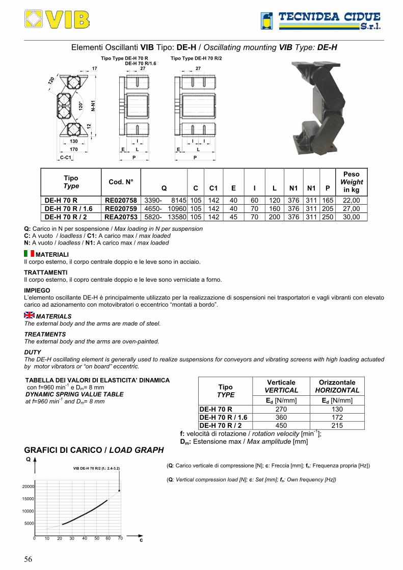
56
Elementi Oscillanti VIB Tipo: DE-H / Oscillating mounting VIB Type: DE-H
I
LP
CC
CC
CC
CC
CC
CC
CCCCCCCCCCCCCCCCCCCCCCCCCCCCCCCCCCCCCC
17
120°
130170
CC
CC
CC
CC
CC12
0
C-C1
CC
CC
CC
CC
CC
CCCCCCCC
CC
CC
CC
CC
CC
CC
CC
CC
CC
CC
CC
CC
CC
CC
CC
CC
CC
E
N-N
1
CCCCCCCC
CC
CC
CC
CC
CC
CC
CC
CC
CC
CC
CC
CC
CC
CC
CC
CC
C
I
CCCCCCCCCCC CCCCCCCCCCC
27
CC
CC
CC
CC
CC
CC
CC
CC
CC
CC
CC
CC
CC
CC
CC
CC
CC
CC
CC
C
CC
CC
CC
CC
CC
CC
CC
CC
CC
CC
CC
CC
C
CC
CC
CC
CC
CC
CC
CCCCCCCCCCCC
CC
CC
CC
CC
CC
CC
CC
CC
CC
CC
CC
CC
C
12CCCCCCCCCCCCCCCCCCCCCCC
LP
CC
CC
CC
CC
CC
CC
CC
CC
CC
CC
CC
CC
CC
CC
CC
CC
C
I
CCCCCCCCCCC
E
CCCCCCCCCCC
CC
27
CC
CC
CC
CC
CC
CC
CC
CC
CC
CC
CC
CC
C
CC
CC
CC
CC
CC
CC
CC
CC
CC
CC
CC
CC
CC
CC
CC
CC
CC
CC
CC
C
CC
CC
CC
CC
CC
CC
CC
CC
CC
CC
CC
CC
C
Tipo Type DE-H 70 RDE-H 70 R/1.6
Q
C C1 E I
L
N1
N1
P Tipo Type Cod. N°
Peso Weight in kg
DE-H 70 R RE020758 3390- 8145 105 142 40 60 120 376 311 165 22,00 DE-H 70 R / 1.6 RE020759 4650- 10960 105 142 40 70 160 376 311 205 27,00 DE-H 70 R / 2 REA20753 5820- 13580 105 142 45 70 200 376 311 250 30,00
Q: Carico in N per sospensione / Max loading in N per suspension C: A vuoto / loadless / C1: A carico max / max loaded N: A vuoto / loadless / N1: A carico max / max loaded
MATERIALI Il corpo esterno, il corpo centrale doppio e le leve sono in acciaio.
TRATTAMENTI Il corpo esterno, il copro centrale doppio e le leve sono verniciate a forno.
IMPIEGO L’elemento oscillante DE-H è principalmente utilizzato per la realizzazione di sospensioni nei trasportatori e vagli vibranti con elevato carico ad azionamento con motovibratori o eccentrico “montati a bordo”.
MATERIALS The external body and the arms are made of steel.
TREATMENTS The external body and the arms are oven-painted.
DUTY The DE-H oscillating element is generally used to realize suspensions for conveyors and vibrating screens with high loading actuated by motor vibrators or “on board” eccentric. TABELLA DEI VALORI DI ELASTICITA’ DINAMICA con f=960 min-1 e Dm= 8 mm DYNAMIC SPRING VALUE TABLE at f=960 min-1 and Dm= 8 mm
Verticale
VERTICAL Orizzontale
HORIZONTAL Tipo TYPE
Ed [N/mm] Ed [N/mm] DE-H 70 R 270 130 DE-H 70 R / 1.6 360 172 DE-H 70 R / 2 450 215
f: velocità di rotazione / rotation velocity [min-1]; Dm: Estensione max / Max amplitude [mm]
GRAFICI DI CARICO / LOAD GRAPH
400 10 20 30
5000
10000
15000
20000
50 60 70
VIB DE-H 70 R/2 (fo: 2.4-3.2)
(Q: Carico verticale di compressione [N]; c: Freccia [mm]; fn: Frequenza propria [Hz]) (Q: Vertical compression load [N]; c: Set [mm]; fn: Own frequency [Hz])
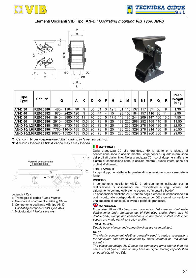
57
Elementi Oscillanti VIB Tipo: AN-D / Oscillating mounting VIB Type: AN-D
CC
CC
CC
CC
CC
CC
CC
CC
CCCCCCCCCCCCCCCCCCC
CCCCCCCCCCCCCCCCCCC
CCCCCCCCCCCCCCCCCCCCCCCCCCCC
CC
CC
CC
CC
CC
CC
CC
CC
N-N
1
M
AH
PQ
D
ØR
ØC ØC
F
G
L
60°
Q
A
C
D
G
F
H
L
M
N
N1
P
Q
R Tipo Type Cod. N°
Peso Weightin kg
AN-D 30 RE020880 485- 1164 90 9 30 31 3 12,5 61 115 137 117 74 50 9 1,30 AN-D 40 RE020882 970- 2425 120 9 50 44 4 15 93 150 184 157 116 80 11 2,90 AN-D 50 RE020884 1940- 3880 150 11 70 60 5 17,5 118 185 244 209 147 100 13,5 7,50 AN-D 60 RE020886 2910- 5820 170 13,5 80 73 6 25 132 220 298 252 168 110 18 11,50 AN-D 70/1.2 RE020888 3880- 8730 185 13,5 90 78 6 25 142 235 329 278 166 120 18 22,00 AN-D 70/1.6 RE020890 7760- 11640 185 13,5 90 78 8 25 186 235 329 278 214 160 18 25,50 AN-D 70/2.0 RE020892 10670- 15520 185 13,5 90 78 8 25 226 235 329 278 260 200 18 29,00
Q: Carico in N per sospensione / Max loading in N per suspension N: A vuoto / loadless / N1: A carico max / max loaded
Verso di avanzamento
G
45°-60°
34
2
1
Feed direction
Legenda / Key: 1: Tramoggia di carico / Load hopper 2: Grondaia di scorrimento / Sliding Chute 3: Componente oscillante VIB tipo AN-D Oscillating component VIB Type AN-D 4: Motovibratori / Motor vibrators
MATERIALI Dalla grandezza 30 alla grandezza 60 le staffe e le piastre di connessione sono in acciaio mentre i corpi doppi e i quadri interni sono dei profilati d’alluminio. Nella grandezza 70 i corpi doppi le staffe e le piastre di connessione sono in acciaio mentre i quadri interni sono dei profilati d’alluminio.
TRATTAMENTI I corpi doppi, le staffe e le piastre di connessione sono verniciate a forno.
IMPIEGO Il componente oscillante AN-D è principalmente utilizzato per la realizzazione di sospensioni nei trasportatori e vagli vibranti ad azionamento con motovibratori o eccentrico “montati a bordo”. Le sospensioni elastiche AN-D hanno degli elementi di connessione più corti rispetto alle corrispondenti grandezze dei DE e quindi consentono una capacità di carico più elevata a parità di grandezza.
MATERIALS From size 30 to 60 clamps and connection links are in steel while double inner body are made out of light alloy profile. From size 70 double body, clamps and connection links are made of steel while inner square are made our of light alloy profile.
TREATMENTS Double body, clamps and connection links are oven painted.
DUTY The elastic component AN-D is generally used to realize suspensions for conveyors and screen actuated by motor vibrators or “on board” eccentric. The elastic mountings AN-D have the connecting arms shorter than the same size of type DE and so they have an higher loading capacity than an equal size of type DE.
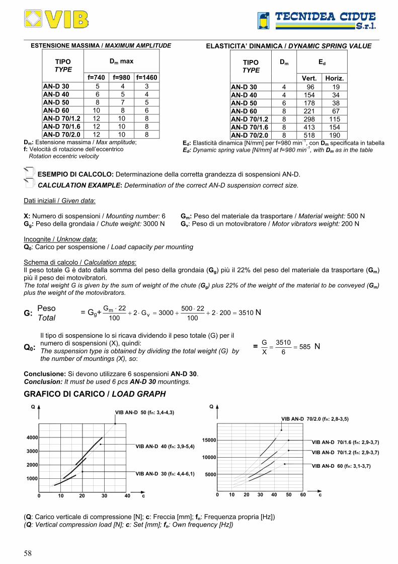
58
ESTENSIONE MASSIMA / MAXIMUM AMPLITUDE
Dm max
TIPO TYPE
f=740 f=980 f=1460 AN-D 30 5 4 3 AN-D 40 6 5 4 AN-D 50 8 7 5 AN-D 60 10 8 6 AN-D 70/1.2 12 10 8 AN-D 70/1.6 12 10 8 AN-D 70/2.0 12 10 8
Dm: Estensione massima / Max amplitude; f: Velocità di rotazione dell’eccentrico Rotation eccentric velocity
ELASTICITA’ DINAMICA / DYNAMIC SPRING VALUE
Dm
Ed
TIPO TYPE
Vert. Horiz.AN-D 30 4 96 19 AN-D 40 4 154 34 AN-D 50 6 178 38 AN-D 60 8 221 67 AN-D 70/1.2 8 298 115 AN-D 70/1.6 8 413 154 AN-D 70/2.0 8 518 190
Ed: Elasticità dinamica [N/mm] per f=980 min-1, con Dm specificata in tabella Ed: Dynamic spring value [N/mm] at f=980 min-1, with Dm as in the table
ESEMPIO DI CALCOLO: Determinazione della corretta grandezza di sospensioni AN-D. CALCULATION EXAMPLE: Determination of the correct AN-D suspension correct size.
Dati iniziali / Given data: X: Numero di sospensioni / Mounting number: 6 Gm: Peso del materiale da trasportare / Material weight: 500 N Gg: Peso della grondaia / Chute weight: 3000 N Gv: Peso di un motovibratore / Motor vibrators weight: 200 N Incognite / Unknow data: Q0: Carico per sospensione / Load capacity per mounting Schema di calcolo / Calculation steps: Il peso totale G è dato dalla somma del peso della grondaia (Gg) più il 22% del peso del materiale da trasportare (Gm) più il peso dei motovibratori. The total weight G is given by the sum of weight of the chute (Gg) plus 22% of the weight of the material to be conveyed (Gm) plus the weight of the motovibrators.
Peso G: Total = Gg+ 35102002
100225003000G2
10022G
vm =⋅+
⋅+=⋅+
⋅ N
Q0: Il tipo di sospensione lo si ricava dividendo il peso totale (G) per il numero di sospensioni (X), quindi: The suspension type is obtained by dividing the total weight (G) by the number of mountings (X), so:
= 5856
3510XG
== N
Conclusione: Si devono utilizzare 6 sospensioni AN-D 30. Conclusion: It must be used 6 pcs AN-D 30 mountings.
GRAFICO DI CARICO / LOAD GRAPH
c300 10 20 40
Q
2000
1000
3000
4000
VIB AN-D 30 (fn: 4,4-6,1)
VIB AN-D 40 (fn: 3,9-5,4)
VIB AN-D 50 (fn: 3,4-4,3)
300 10 20 40 50 60
10000
5000
15000
VIB AN-D 60 (fn: 3,1-3,7)
c
Q
VIB AN-D 70/1.2 (fn: 2,9-3,7)
VIB AN-D 70/1.6 (fn: 2,9-3,7)
VIB AN-D 70/2.0 (fn: 2,8-3,5)
(Q: Carico verticale di compressione [N]; c: Freccia [mm]; fn: Frequenza propria [Hz]) (Q: Vertical compression load [N]; c: Set [mm]; fn: Own frequency [Hz])
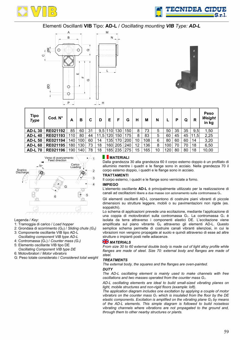
59
Elementi Oscillanti VIB Tipo: AD-L / Oscillating mounting VIB Type: AD-L
B
C
E
F
G
H
L
N
ØD
P
QØR
A
B
C
D
E
F
G H
M
N
L
P
Q
R Tipo Type Cod. N°
Peso Weight in kg
AD-L 30 RE021192 85 60 31 9,5 110 130 150 8 73 5 50 35 35 9,5 1,50 AD-L 40 RE021193 110 80 44 11,5 120 150 175 8 83 5 60 45 45 11,5 2,25 AD-L 50 RE021194 140 100 60 14 135 170 200 10 108 6 80 60 60 14 3,20 AD-L 60 RE021195 180 130 73 18 160 205 240 12 136 8 100 70 70 18 6,50 AD-L 70 RE021196 190 140 78 18 185 235 275 15 165 10 120 80 80 18 10,00
Verso di avanzamento
30°
1
2
5
4
6
3
G
Scarico
CaricoFeed direction
Loading
Discharge
Legenda / Key: 1: Tramoggia di carico / Load hopper 2: Grondaia di scorrimento (G2) / Sliding chute (G2) 3: Componente oscillante VIB tipo AD-L Oscillating component VIB type AD-L 4: Contromassa (G1) / Counter mass (G1) 5: Elemento oscillante VIB tipo DE Oscillating Component VIB type DE 6: Motovibratori / Motor vibrators G: Peso totale considerato / Considered total weight
MATERIALI Dalla grandezza 30 alla grandezza 60 il corpo esterno doppio è un profilato di alluminio mentre i quadri e le flange sono in acciaio. Nella grandezza 70 il corpo esterno doppio, i quadri e le flange sono in acciaio.
TRATTAMENTI Il corpo esterno, i quadri e le flange sono verniciate a forno.
IMPIEGO L’elemento oscillante AD-L è principalmente utilizzato per la realizzazione di canali ad oscillazioni libere a due masse con azionamento sulla contromassa G1.
Gli elementi oscillanti AD-L consentono di costruire piani vibranti di piccole dimensioni su strutture leggere, mobili o su pavimentazioni non rigide (es. soppalchi). Lo schema di applicazioni prevede una eccitazione, mediante l’applicazione di una coppia di motovibratori sulla contromassa G1. La contromassa G1 è isolata da terra attraverso i componenti elastici DE. L’eccitazione viene amplificata sul piano vibrante G2 attraverso gli elementi AD-L. Questo semplice schema permette di costruire canali vibranti silenziosi, in cui le vibrazioni non vengono propagate al suolo e quindi attraverso di esse ad altre strutture o impianti posti nelle adiacenze.
MATERIALS From size 30 to 60 external double body is made out of light alloy profile while flanges are made of steel. Size 70: external body and flanges are made of steel.
TREATMENTS The external body, the squares and the flanges are oven-painted.
DUTY The AD-L oscillating element is mainly used to make channels with free oscillations and two masses operated from the counter mass G1.
AD-L oscillating elements are ideal to build small-sized vibrating planes on light, mobile structures and non-rigid floors (example: loft). The application diagram includes one excitation by applying a couple of motor vibrators on the counter mass G1 which is insulated from the floor by the DE elastic components. Excitation is amplified on the vibrating plane G2 by means of the AD-L elements. This simple diagram is followed to build noiseless vibrating channels where vibrations are not propagated to the ground and, through them to other nearby structures or plants.

60
Affinché il trasportatore possa operare al massimo delle prestazioni la distanza tra gli AD-L non deve superare 1,5 metri e la massa G1 [N] deve essere: 2·G [N] ≤ G1 ≤ 3·G [N] (caso ideale). / In order to optimize the conveyor performance, the distance among AD-L should not exceed 1.5 metres and the mass G1 [N] must not be: 2·G [N] ≤ G1 ≤ 3·G [N] (ideal case).
TABELLA DELLE SPECIFICHE FUNZIONALI / FUNCTIONAL SPECIFICATION TABLE
f=740 f=980 f=1460 TIPO TYPE
Dm Ed Q Dm Ed Q Dm Ed Q AD-L 30 / / / 4 134 139 3 120 101 AD-L 40 / / / 5 154 230 4 149 144 AD-L 50 8 182 499 7 192 379 / / / AD-L 60 10 230 893 8 250 662 / / / AD-L 70 11 336 1363 9 355 998 / / /
ESEMPIO DI CALCOLO: Determinazione del numero di sospensioni necessarie per un trasportatore vibrante, utilizzando dei gruppi composti da AD-L 50
CALCULATION EXAMPLE: Determination of the suspension number in a oscillating conveyor, using AD-L 50
Dati iniziali / Given data:
n: Velocità di rotazione del motovibratore: Motor vibrators rotation velocity: 980 min-1 G1: Peso della contromassa:
Counter mass weight: 2590 N
Dm: Estensione massima: Maximum amplitude: 7 mm G2: Peso del grondaia:
Sliding chute weight: 840 N
Ed: Elasticità dinamica: Dynamic spring value: 192 [N/mm] Gm: Peso del materiale da trasportare:
Material weight: 100 N
Re: Raggio dell’eccentrico del motovibratore: Eccentric radius: 3,5 mm
Incognite / Unknow data: X: numero di sospensioni / suspension number Et: Elasticità totale / Total spring value J: Indice della macchina vibrante / Oscillating machine factor Gt: Peso complessivo / Assembly weight Schema di calcolo / Calculation steps:
Il peso totale G è dato dalla somma del peso della grondaia (G2) più il 22% del peso del materiale da trasportare (Gm) The total weight G is given by the sum of weight of the chute (G2) plus 22% of the weight of the material to be conveyed (Gm)
Peso G: Total = G2+ 862
10022100840
10022Gm =
⋅+=
⋅ N
Verifica del rapporto tra le masse G1 e G / Mass ratio (G1/G) check = 38622590
GG1 == (Valore ideale / Best value)
Et = 6,69330980
86225908622590
98101
60n2
GGGG
98101 22
1
1 =
⋅π⋅
+⋅
⋅=
⋅π⋅⋅
+⋅
⋅ N/mm
X: L’elasticità totale Et della sospensione deve essere approssimativamente il 10% superiore a quello dell’elasticità dinamica, quindi: The total spring value Et of the mounting must be at least 10% greater that than the dynamic spring value, so:
= 0,41929,0
6,693E9,0
E
d
t =⋅
=⋅
Conclusione: Si devono utilizzare pezzi 4 AD-L 50. Conclusion: It must be used 4 pcs AD-L 50.
J: Indice della macchina vibrante: Oscillating machine factor: =
29810
Dn60
2m
2
⋅
⋅
⋅π⋅
= 75,329810
798030
2
=⋅
⋅
⋅π
Scelta delle sospensioni VIB tipo DE per l’intera struttura / Selection of VIB type DE mountigs for the whole structure: Gt: Peso complessivo / Assembly weight = G1+G = 2590 + 862 = 3452 N Numero di appoggi richiesti / Support required number: 4
Carico per appoggio / Load on each support: 8634
3452= N
Conclusione: Si devono utilizzare pezzi 4 DE 50 Conclusion: It must be used 4 pcs DE 50.
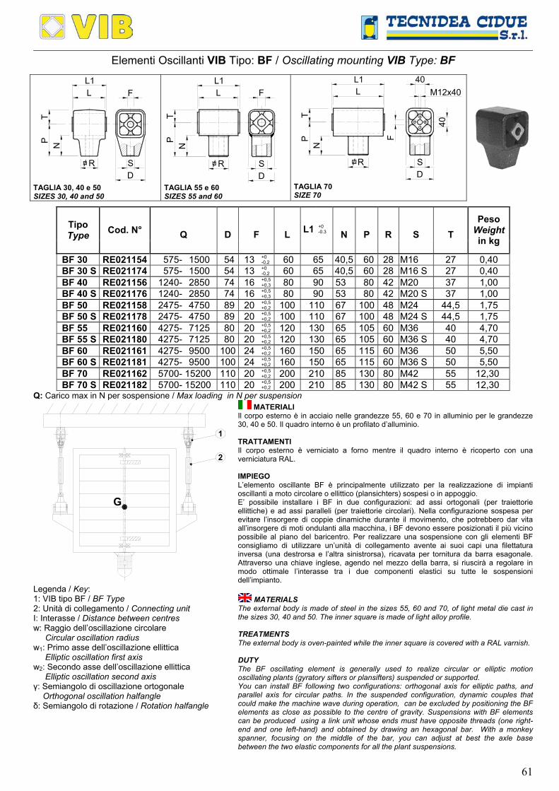
61
Elementi Oscillanti VIB Tipo: BF / Oscillating mounting VIB Type: BF
TP N
D/ R S
L F
TAGLIA 30, 40 e 50 SIZES 30, 40 and 50
PN
D/ R S
L
T
F
TAGLIA 55 e 60 SIZES 55 and 60
PN
L
T
/ RDS
40
F
M12x40
TAGLIA 70 SIZE 70
Q
D
F
L
L1
+0 -0.3
N
P
R
S
T Tipo Type Cod. N°
Peso Weightin kg
BF 30 RE021154 575- 1500 54 13 +0 -0,2 60 65 40,5 60 28 M16 27 0,40
BF 30 S RE021174 575- 1500 54 13 +0 -0,2 60 65 40,5 60 28 M16 S 27 0,40
BF 40 RE021156 1240- 2850 74 16 +0,5 +0,3 80 90 53 80 42 M20 37 1,00
BF 40 S RE021176 1240- 2850 74 16 +0,5 +0,3 80 90 53 80 42 M20 S 37 1,00
BF 50 RE021158 2475- 4750 89 20 +0,5 +0,2 100 110 67 100 48 M24 44,5 1,75
BF 50 S RE021178 2475- 4750 89 20 +0,5 +0,2 100 110 67 100 48 M24 S 44,5 1,75
BF 55 RE021160 4275- 7125 80 20 +0,5 +0,2 120 130 65 105 60 M36 40 4,70
BF 55 S RE021180 4275- 7125 80 20 +0,5 +0,2 120 130 65 105 60 M36 S 40 4,70
BF 60 RE021161 4275- 9500 100 24 +0,5 +0,2 160 150 65 115 60 M36 50 5,50
BF 60 S RE021181 4275- 9500 100 24 +0,5 +0,2 160 150 65 115 60 M36 S 50 5,50
BF 70 RE021162 5700- 15200 110 20 +0,5 +0,2 200 210 85 130 80 M42 55 12,30
BF 70 S RE021182 5700- 15200 110 20 +0,5 +0,2 200 210 85 130 80 M42 S 55 12,30
Q: Carico max in N per sospensione / Max loading in N per suspension
1
2
G
Legenda / Key: 1: VIB tipo BF / BF Type 2: Unità di collegamento / Connecting unit I: Interasse / Distance between centres w: Raggio dell’oscillazione circolare Circular oscillation radius w1: Primo asse dell’oscillazione ellittica Elliptic oscillation first axis w2: Secondo asse dell’oscillazione ellittica Elliptic oscillation second axis γ: Semiangolo di oscillazione ortogonale Orthogonal oscillation halfangle δ: Semiangolo di rotazione / Rotation halfangle
MATERIALI Il corpo esterno è in acciaio nelle grandezze 55, 60 e 70 in alluminio per le grandezze 30, 40 e 50. Il quadro interno è un profilato d’alluminio. TRATTAMENTI Il corpo esterno è verniciato a forno mentre il quadro interno è ricoperto con una verniciatura RAL. IMPIEGO L’elemento oscillante BF è principalmente utilizzato per la realizzazione di impianti oscillanti a moto circolare o ellittico (plansichters) sospesi o in appoggio. E’ possibile installare i BF in due configurazioni: ad assi ortogonali (per traiettorie ellittiche) e ad assi paralleli (per traiettorie circolari). Nella configurazione sospesa per evitare l’insorgere di coppie dinamiche durante il movimento, che potrebbero dar vita all’insorgere di moti ondulanti alla macchina, i BF devono essere posizionati il più vicino possibile al piano del baricentro. Per realizzare una sospensione con gli elementi BF consigliamo di utilizzare un’unità di collegamento avente ai suoi capi una filettatura inversa (una destrorsa e l’altra sinistrorsa), ricavata per tornitura da barra esagonale. Attraverso una chiave inglese, agendo nel mezzo della barra, si riuscirà a regolare in modo ottimale l’interasse tra i due componenti elastici su tutte le sospensioni dell’impianto.
MATERIALS The external body is made of steel in the sizes 55, 60 and 70, of light metal die cast in the sizes 30, 40 and 50. The inner square is made of light alloy profile. TREATMENTS The external body is oven-painted while the inner square is covered with a RAL varnish. DUTY The BF oscillating element is generally used to realize circular or elliptic motion oscillating plants (gyratory sifters or plansifters) suspended or supported. You can install BF following two configurations: orthogonal axis for elliptic paths, and parallel axis for circular paths. In the suspended configuration, dynamic couples that could make the machine wave during operation, can be excluded by positioning the BF elements as close as possible to the centre of gravity. Suspensions with BF elements can be produced using a link unit whose ends must have opposite threads (one right-end and one left-hand) and obtained by drawing an hexagonal bar. With a monkey spanner, focusing on the middle of the bar, you can adjust at best the axle base between the two elastic components for all the plant suspensions.

62
CONFIGURAZIONE – TIPO DI TRAIETTORIA CONFIGURATION – TRAJECTORY TYPE
I I
5°2°= ± = ±2°
2°= ±
= ±
w
w1
w2
A B A: Configurazione per oscillazione circolare (assi ortogonali) B: Configurazione per oscillazione ellittica (assi paralleli) A: Configuration for circular oscillation (orthogonal axis) B: Configuration for elliptic oscillation (parallel axis)
ESEMPIO DI CALCOLO: Determinazione della corretta grandezza di sospensioni BF CALCULATION EXAMPLE: Determination of BF suspension correct size.
Dati iniziali / Given data: Configurazione “A” per oscillazione circolare (assi ortogonali) “A” configuration for circular oscillation (orthogonal axis) w1:
Raggio di oscillazione circolare: Circular oscillation radius: 18 mm
γ: Semiangolo di oscillazione ortogonale: Halfangle orthogonal oscillation: 2° G: Peso della massa oscillante:
Oscillating mass weight: 7000 N
n: Velocità di rotazione del motore: Motor rotation velocity: 150 min-1 X: Numero di sospensioni da utilizzare:
Required suspension number: 4
Incognite / Unknow data: Q0: Carico per sospensione / Load for each suspension Schema di calcolo / Calculation steps:
I: Interasse minimo di sospensione Minimum distance between centres
= 5143518
)2(tan18
)(tanw1 ==
°=
γmm
Q0: Il tipo di sospensione lo si ricava dividendo il peso totale (G) per il numero di sospensioni (X),quindi: The suspension type is obtained by dividing the total weight (G) by the number of mountings (X), so:
= ==4
7000XG 1750 N
Conclusione: Si devono utilizzare 4 sospensioni ognuna formata da 2 componenti BF 40. Conclusion: It must be used 4 mountings, each comprising 2 BF 40 elements.

63
Giunti VIB Tipo: CR-P / Universal Joint VIB Type: CR-P L1
L
F
A
FF B
CR-P110 F5 Ø30x30G
H
M
D
F B
TAGLIA 30, 40, 50, 80, 100 e 110 SIZES 30, 40, 50, 80, 100 and 110
A
F
F B
G
H
M
D
F
F B
L1
L
TAGLIA 60 e 70 SIZES 60 and 70
Q
n
A
B
D
F
G
H
M
L
L1 Tipo Type Cod. N°
Peso Weight in kg
CR-P 20 RE020802 150 1150 54 5 +0,5 +0,0 27 10 ±0,2 - - - 60 65 0,44
CR-P 30 RE020804 288 760 64 6 +0,5 +0,0 32 12 ±0,3 - - - 80 85 0,65
CR-P 40 RE020806 750 760 90 8 +0,5 +0,0 45 20 ±0.4 - - - 100 105 2,10
CR-P 50 RE020808 1550 760 120 10 +0,5 +0,0 60 25 ±0.4 - - - 120 130 4,10
CR-P 60 RE020810 2800 560 156 12 +0,5 +0,0 72 35 ±0.5 - - - 150 160 4,50
CR-P 70 RE020812 5350 385 172 M12 78 40 ±0.5 40 70 12,25 200 210 11,50 CR-P 80 RE020814 9550 280 200 M16 100 45 50 80 16,50 300 310 35,00 CR-P 100 RE020818 18950 145 272 M20 136 60 50 90 20,50 400 410 80,00 CR-P 110 RE020820 28900 92 340 M24 170 75 50 100 25 400 410 135,00 CR-P 110 F5 RE020822 38500 92 340 M24 170 75 50 100 25 500 510 160,00
Q: Carico max in N per sospensione / Maximum loading in N per suspension. n: Numero di giri max in min-1 per β ≮10° con variazione ≮ ±5° dalla posizione 0 / Max rotation velocity in min-1 at the max angle ≮10° from 0 ≮ ±5°.
Re
Ι
G
1
2
Scarico
CaricoLoading
Discharge
Legenda: 1: Tramoggia di carico / Load hopper 2: VIB tipo CR-P / CR-P Type I: Interasse / Distance between centres Re: Raggio dell’eccentrico / Crank radius ß: Angolo di lavoro totale: 10° (±5° dalla posizione 0) Total angle working: 10° (±5° from 0 position) G: Carico dinamico oscillante / Dynamic oscillating load
MATERIALI Il corpo esterno è in acciaio nelle grandezze 20, 30, 40, 80, 100, 110. In ghisa nelle grandezze 60 e 70. I quadri interni sono un profilato d’alluminio dalla grandezza 20 alla 70 in acciaio dalla 80 alla 110. TRATTAMENTI Il corpo esterno è verniciato a forno mentre il quadro interno è ricoperto con una vernice RAL. IMPIEGO Il componente oscillante CR-P è principalmente utilizzato per la realizzazione di impianti oscillanti a moto circolare (plansichters) sospesi o in appoggio. Per evitare l’insorgere di coppie dinamiche durante il movimento, che potrebbero dar vita all’insorgere di moti non piani ma ondulanti, il componente elastico superiore CR-P deve essere il più possibile sullo stesso piano del baricentro della macchina. L’angolo di oscillazione totale ß non deve superare i 10° e tale angolo dipende dall’interasse tra il giunto superiore e quello inferiore.
MATERIALS The external body is made of steel. The inner squares are made of light alloy profile from size 20 to 70, of steel from size 80 to 110. TREATMENTS The external body is oven-painted while the inner square is covered with a RAL varnish. DUTY The CR-P oscillating component is generally used to realize circular motion oscillating plants (plansifters) suspended or supported. The onset of dynamic torques that could generate wavy rather than plane motion during the movement, can be excluded by aligning the upper CR-P elastic component as much as possible with the centre of gravity of the machine. The total oscillation angle ß should not exceed 10° and this angle depends on the axle base between the upper and lower joints.

64
ESEMPIO DI CALCOLO: Determinazione della corretta grandezza di sospensioni CR-P CALCULATION EXAMPLE: Determination of CR-P suspension correct size
Dati iniziali / Given data:
G: Peso oscillante: Oscillating weight: 7000 N X: Numero di sospensioni da utilizzare:
Required suspension number: 4
n: Velocità di rotazione del motore: Motor rotation velocity: 300 min-1 Fs:
Fattore sicurezza: Safety factor:
Re: Raggio dell’eccentrico: Eccentric radius: 18 mm
1,3 (Solo per impianti in appoggio / Only for supported plants)
Incognite / Unknow data: Q0: Carico per sospensione / Load on each suspension Schema di calcolo / Calculation steps:
I: Interasse minimo di sospensione Minimum distance between centres = 200
09,018
)5(tan18
)2/(tanRe ==
°=
βmm
Q0: Il tipo di sospensione lo si ricava dividendo il peso totale (G) moltiplicato per il fattore di sicurezza (Fs) per il numero di sospensioni (X), quindi: The suspension type is obtained by dividing the total weight (G)multiplied by the safety factor (Fs) by the number of mountings (X), so:
= =⋅
=4
3,17000XG 2275 N
Conclusione: Si devono utilizzare 4 sospensioni ognuna formata da 2 componenti CR-P 60. Conclusion: It must be used 4 mountings, each comprising 2 pcs CR-P 60 elements.
Staffa tipo SBSupport type SB