SPECIFICA PRODOTTO ISTRUZIONI PER L’USO E LA … · da altri mezzi, quali i controlli...
22
1/11 Divisione della BETA UTENSILI spa Via Volta. 18 - 20845 SOVICO (MB) ITALY Tel. +39.039.20771-Fax + 39.039.2010742 SPECIFICA PRODOTTO ISTRUZIONI PER L’USO E LA MANUTENZIONE Informazioni tecniche Condizioni d’uso previste e limiti operativi Prescrizioni per gli operatori Rischi residui Modalità e frequenza d’ispezioni periodiche d’idoneità GOLFARE MASCHIO PER SOLLEVAMENTO DIN 580:2010 ART. 8040EN / 8040EZ La lingua originale della presente specifica è quella Italiana Sede produttiva Accessori per funi ROBUR Zona Industriale – C.da S. Nicola 67039 SULMONA (L’AQUILA) Tel. +39.0864.2504.1 – Fax +39.0864.253132 www.roburitaly.com – [email protected] R/SP/8040/06 Data 20/12/2017
Transcript of SPECIFICA PRODOTTO ISTRUZIONI PER L’USO E LA … · da altri mezzi, quali i controlli...

1/11
Divisione della BETA UTENSILI spa Via Volta. 18 - 20845 SOVICO (MB) ITALY Tel. +39.039.20771-Fax + 39.039.2010742
SPECIFICA PRODOTTO
ISTRUZIONI PER L’USO E LA MANUTENZIONE Informazioni tecniche
Condizioni d’uso previste e limiti operativi
Prescrizioni per gli operatori
Rischi residui
Modalità e frequenza d’ispezioni periodiche d’idoneità
GOLFARE MASCHIO PER SOLLEVAMENTO
DIN 580:2010 ART. 8040EN / 8040EZ
La lingua originale della presente specifica è quella Italiana
Sede produttiva Accessori per funi ROBUR Zona Industriale – C.da S. Nicola 67039 SULMONA (L’AQUILA)
Tel. +39.0864.2504.1 – Fax +39.0864.253132 www.roburitaly.com – [email protected]
R/SP/8040/06 Data 20/12/2017

2/11
Divisione della BETA UTENSILI spa Via Volta. 18 - 20845 SOVICO (MB) ITALY Tel. +39.039.20771-Fax + 39.039.2010742
1) CARATTERISTICHE TECNICHE
Materiale:
C15E + AL (0.025 ÷0.050%)
Trattamento Termico:
Normalizzato
Norme di riferimento:
Golfare DIN 580:2010
Materiale UNI EN 10084
Trattamento Superficiale:
• Art. 8040EN:
Nero (non trattato) tal quale di forgiatura e di
lavorazione meccanica
• Art. 8040EZ:
Zincato A2E EN ISO 4042
Il collaudo viene eseguito in base a specifiche e regole interne in riferimento
alla norma UNI EN ISO 9001.
L’articolo è conforme alla Direttiva Macchine 2006/42/CE
3/11
Divisione della BETA UTENSILI spa Via Volta. 18 - 20845 SOVICO (MB) ITALY Tel. +39.039.20771-Fax + 39.039.2010742
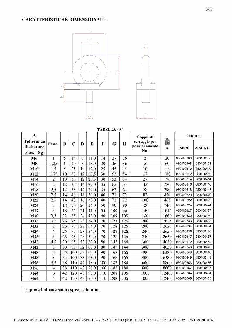
CARATTERISTICHE DIMENSIONALI:
TABELLA “A”
A Tolleranze
filettature
classe 8g
Passo B C D E F G H
Coppie di
serraggio per
posizionamento
Nm
g
CODICE
NERI ZINCATI
M6 1 6 14 6 11.0 14 27 26 2 20 080400306 080400406
M8 1,25 6 20 8 13.0 20 36 36 5 60 080400308 080400408
M10 1,5 8 25 10 17.0 25 45 45 10 110 080400310 080400410
M12 1,75 10 30 12 20,5 30 53 54 17 180 080400312 080400412
M14 2 10 30 12 20,5 30 53 54 27 190 080400314 080400414
M16 2 12 35 14 27.0 35 62 63 42 280 080400316 080400416
M18 2,5 12 35 14 27.0 35 62 63 58 290 080400318 080400418
M20 2,5 14 40 16 30.0 40 71 72 83 450 080400320 080400420
M22 2,5 14 40 16 30.0 40 71 72 100 465 080400322 080400422
M24 3 18 50 20 36.0 50 90 90 120 740 080400324 080400424
M27 3 18 55 21 41.0 55 100 96 150 1015 080400327 080400427
M30 3,5 22 65 24 45.0 60 109 108 180 1660 080400330 080400430
M33 3,5 26 75 28 54.0 70 128 126 200 2625 080400333 080400433
M33 2 26 75 28 54.0 70 128 126 200 2625 080400334 080400434
M36 4 26 75 28 54.0 70 128 126 240 2650 080400336 080400436
M36 3 26 75 28 54.0 70 128 126 240 2650 080400337 080400437
M42 4,5 30 85 32 63.0 80 147 144 300 4030 080400342 080400442
M42 3 30 85 32 63.0 80 147 144 300 4030 080400343 080400443
M48 5 35 100 38 68.0 90 168 166 400 6380 080400348 080400448
M48 3 35 100 38 68.0 90 168 166 400 6380 080400349 080400449
M56 5,5 38 110 42 78.0 100 187 184 600 8800 080400356 080400456
M56 4 38 110 42 78.0 100 187 184 600 8800 080400357 080400457
M64 6 42 120 48 90.0 110 208 206 1000 12400 080400364 080400464
M64 4 42 120 48 90.0 110 208 206 1000 12400 080400365 080400465
Le quote indicate sono espresse in mm.

4/11
Divisione della BETA UTENSILI spa Via Volta. 18 - 20845 SOVICO (MB) ITALY Tel. +39.039.20771-Fax + 39.039.2010742
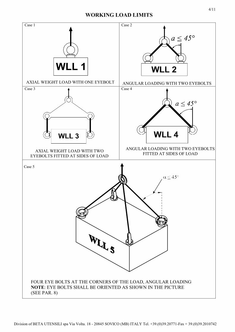
CARICHI DI LAVORO WLL
Caso 1 Caso 2
Caso 3 Caso 4
Caso 5
SINGOLO GOLFARE TIRO ASSIALE DUE GOLFARI TIRO ANGOLATO
DUE GOLFARI AI LATI DEL CARICO DUE GOLFARI AI LATI, TIRO ANGOLATO
QUATTRO GOLFARI AI LATI DEL CARICO TIRO ANGOLATO
N.B. I GOLFARI DEVONO ESSSERE ORIENTATI COME IN FIGURA
(VEDERE PARAGRAFO 8 )
5/11
Divisione della BETA UTENSILI spa Via Volta. 18 - 20845 SOVICO (MB) ITALY Tel. +39.039.20771-Fax + 39.039.2010742
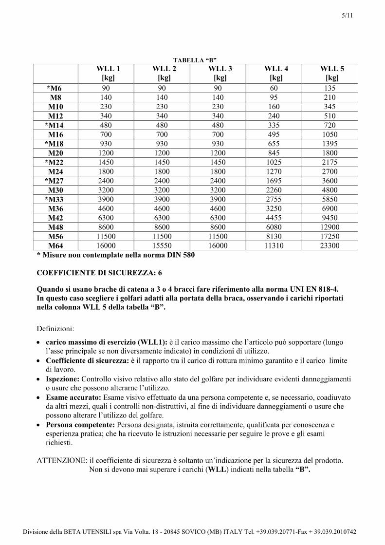
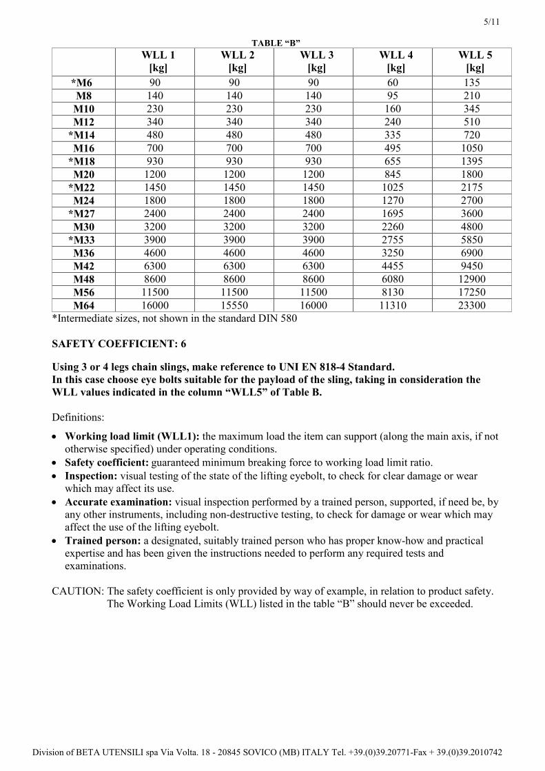
TABELLA “B”
WLL 1
[kg]
WLL 2
[kg]
WLL 3
[kg]
WLL 4
[kg]
WLL 5
[kg]
*M6 90 90 90 60 135
M8 140 140 140 95 210
M10 230 230 230 160 345
M12 340 340 340 240 510
*M14 480 480 480 335 720
M16 700 700 700 495 1050
*M18 930 930 930 655 1395
M20 1200 1200 1200 845 1800
*M22 1450 1450 1450 1025 2175
M24 1800 1800 1800 1270 2700
*M27 2400 2400 2400 1695 3600
M30 3200 3200 3200 2260 4800
*M33 3900 3900 3900 2755 5850
M36 4600 4600 4600 3250 6900
M42 6300 6300 6300 4455 9450
M48 8600 8600 8600 6080 12900
M56 11500 11500 11500 8130 17250
M64 16000 15550 16000 11310 23300
* Misure non contemplate nella norma DIN 580
COEFFICIENTE DI SICUREZZA: 6
Quando si usano brache di catena a 3 o 4 bracci fare riferimento alla norma UNI EN 818-4.
In questo caso scegliere i golfari adatti alla portata della braca, osservando i carichi riportati
nella colonna WLL 5 della tabella “B”.
Definizioni:
• carico massimo di esercizio (WLL1): è il carico massimo che l’articolo può sopportare (lungo
l’asse principale se non diversamente indicato) in condizioni di utilizzo.
• Coefficiente di sicurezza: è il rapporto tra il carico di rottura minimo garantito e il carico limite
di lavoro.
• Ispezione: Controllo visivo relativo allo stato del golfare per individuare evidenti danneggiamenti
o usure che possono alterarne l’utilizzo.
• Esame accurato: Esame visivo effettuato da una persona competente e, se necessario, coadiuvato
da altri mezzi, quali i controlli non-distruttivi, al fine di individuare danneggiamenti o usure che
possono alterare l’utilizzo del golfare.
• Persona competente: Persona designata, istruita correttamente, qualificata per conoscenza e
esperienza pratica; che ha ricevuto le istruzioni necessarie per seguire le prove e gli esami
richiesti.
ATTENZIONE: il coefficiente di sicurezza è soltanto un’indicazione per la sicurezza del prodotto.
Non si devono mai superare i carichi (WLL) indicati nella tabella “B”.

6/11
Divisione della BETA UTENSILI spa Via Volta. 18 - 20845 SOVICO (MB) ITALY Tel. +39.039.20771-Fax + 39.039.2010742
2) SPECIFICHE DI COLLAUDO
L’accessorio è sottoposto ad una serie di severi controlli a campione per accertarne la funzionalità
prestazionale e la rispondenza alle specifiche.
La numerosità del campione e i relativi piani di campionamento, sono scelti in funzione della
caratteristica da verificare in accordo e per quanto previsto dalla norma UNI ISO 2859/1, ed i risultati
archiviati nell’ufficio qualità dello stabilimento di Sulmona.
2.A Controllo dimensionale Verifica che le dimensioni dell’articolo rientrino nelle tolleranze stabilite dalla norma
DIN 580:2010
2.B Controllo visivo Verifica la presenza di eventuali imperfezioni dovute a stampaggio, lavorazione
meccanica, rivestimento superficiale e rispondenza della marcatura a disegni di fase
interni.
2.C Analisi chimica Verifica rispondenza della composizione chimica del materiale C15E, entro i limiti
stabiliti dalla norma UNI EN 10084.
2.D Analisi metallografica Verifica il processo di normalizzazione: a 500 ingrandimenti si deve riscontrare una
distribuzione omogenea di ferrite e perlite.
2.E Prove di trazione Verifica che l’accessorio sottoposto ad una trazione, arrivi a rottura, dopo che la
forza applicata, abbia almeno superato il carico di lavoro moltiplicato per il
coefficiente di sicurezza.
La prova è eseguita in accordo con la norma UNI 10002/1
3) COME LEGGERE LA MARCATURA:
Sull’accessorio sono stampate in maniera indelebile marcature e sigle che identificano il prodotto e
definiscono le caratteristiche e le applicazioni.
1) Materiale
2) Carico massimo di esercizio (WLL1)
3) Indicatore di tiro assiale
4) Sigla produttore
5) Misura della filettatura
6) Marcatura CE
7) Identificazione del lotto di fabbricazione, (sigla
alfanumerica)

7/11
Divisione della BETA UTENSILI spa Via Volta. 18 - 20845 SOVICO (MB) ITALY Tel. +39.039.20771-Fax + 39.039.2010742
4) AVVERTENZE GENERALI
Il manuale deve essere custodito da persona responsabile allo scopo preposta, in un luogo idoneo,
affinché esso risulti sempre disponibile per la consultazione nel miglior stato di conservazione. In
caso di smarrimento o deterioramento, la documentazione dovrà essere prontamente sostituita
scaricandola dal sito del costruttore: www.roburitaly.com
Il costruttore si riserva la proprietà materiale ed intellettuale del presente manuale e ne vieta la
modifica, anche parziale, per fini commerciali.
Con riferimento a quanto riportato in queste istruzioni d’uso la BETA UTENSILI S.P.A. declina ogni
responsabilità in caso di:
• Uso degli accessori contrario alle leggi nazionali sulla sicurezza e
sull’antinfortunistica.
• Errata scelta o predisposizione dell’apparecchio di sollevamento con il quale saranno
connessi.
• Mancata o errata osservanza delle istruzioni per l’uso.
• Modifiche agli accessori.
• Uso improprio e omessa manutenzione ordinaria.
• Uso combinato ad accessori non conformi.
!ATTENZIONE: I dati di marcatura non devono essere rimossi con molature o abrasioni,
(neanche accidentali, i golfari senza riferimenti di identificazione devono essere resi
inutilizzabili e rottamati).
Non è consentito apporre caratteri aggiuntivi a quelli di fabbricazione.
5) CRITERI DI SCELTA
I parametri che devono essere attentamente considerati nella scelta del golfare sono:
5.A IL CARICO MASSIMO DI ESERCIZIO
Il peso del carico da sollevare deve essere inferiore o uguale al valore del carico massimo di
esercizio (WLL1) previsto per il golfare preso in considerazione, stampato sul prodotto e riportato
nella tabella “B”.
Nel sollevamento a tiro inclinato con 2 o più golfari la portata massima indicata sul prodotto non è
più valida.
In questo caso il carico massimo di esercizio da applicare è quello riportato nella tabella “B” alla
voce “WLL2 e WLL5” coi golfari fissati sulla superficie del carico e alla voce “WLL3 / WLL4”
coi golfari fissati sui lati del carico.
Non superare mai i 45 gradi tra l’asse del golfare e la fune di tiro.
ASSE DEL GOLFARE MA 45
ASSE DEL GOLFAREMAX 45°
8/11
Divisione della BETA UTENSILI spa Via Volta. 18 - 20845 SOVICO (MB) ITALY Tel. +39.039.20771-Fax + 39.039.2010742
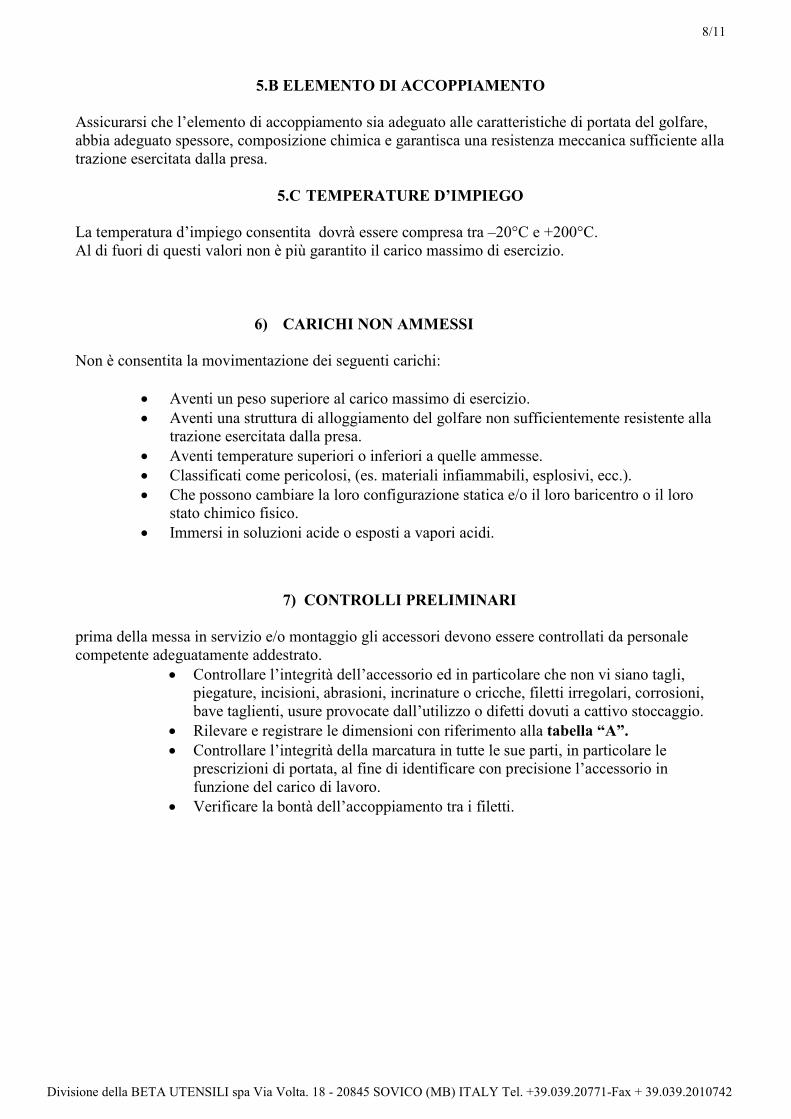
5.B ELEMENTO DI ACCOPPIAMENTO
Assicurarsi che l’elemento di accoppiamento sia adeguato alle caratteristiche di portata del golfare,
abbia adeguato spessore, composizione chimica e garantisca una resistenza meccanica sufficiente alla
trazione esercitata dalla presa.
5.C TEMPERATURE D’IMPIEGO
La temperatura d’impiego consentita dovrà essere compresa tra –20°C e +200°C.
Al di fuori di questi valori non è più garantito il carico massimo di esercizio.
6) CARICHI NON AMMESSI
Non è consentita la movimentazione dei seguenti carichi:
• Aventi un peso superiore al carico massimo di esercizio.
• Aventi una struttura di alloggiamento del golfare non sufficientemente resistente alla
trazione esercitata dalla presa.
• Aventi temperature superiori o inferiori a quelle ammesse.
• Classificati come pericolosi, (es. materiali infiammabili, esplosivi, ecc.).
• Che possono cambiare la loro configurazione statica e/o il loro baricentro o il loro
stato chimico fisico.
• Immersi in soluzioni acide o esposti a vapori acidi.
7) CONTROLLI PRELIMINARI
prima della messa in servizio e/o montaggio gli accessori devono essere controllati da personale
competente adeguatamente addestrato.
• Controllare l’integrità dell’accessorio ed in particolare che non vi siano tagli,
piegature, incisioni, abrasioni, incrinature o cricche, filetti irregolari, corrosioni,
bave taglienti, usure provocate dall’utilizzo o difetti dovuti a cattivo stoccaggio.
• Rilevare e registrare le dimensioni con riferimento alla tabella “A”.
• Controllare l’integrità della marcatura in tutte le sue parti, in particolare le
prescrizioni di portata, al fine di identificare con precisione l’accessorio in
funzione del carico di lavoro.
• Verificare la bontà dell’accoppiamento tra i filetti.

9/11
Divisione della BETA UTENSILI spa Via Volta. 18 - 20845 SOVICO (MB) ITALY Tel. +39.039.20771-Fax + 39.039.2010742
8) INSTALLAZIONE ISTRUZIONI PER IL MONTAGGIO
Durante l’installazione dell’accessorio indossare i dispositivi di protezione adeguati:
guanti, scarpe antinfortunistiche, elmetto, etc.
L’istallazione si effettua avvitando a fondo il golfare fino a portarlo a totale contatto con la superficie
del corpo da sollevare, applicando la coppia di serraggio indicata nella tabella “A”. La coppia di
serraggio ammette una tolleranza di ±5%.
Verificare che le superfici d’appoggio (golfare-corpo da sollevare) siano complanari.
Nella situazione in cui operano contemporaneamente due o più golfari, questi devono avere gli anelli
di aggancio orientati sul medesimo piano, (“condizione ammessa” nel disegno sottostante).
Al fine di ottenere questa condizione è ammesso l’uso di spessori adeguati, da porre tra il golfare ed
il corpo da sollevare.
Tali spessori devono avere un diametro del foro leggermente superiore al diametro del filetto, ed un
diametro esterno pari almeno al piano d’appoggio del golfare, ed avere uno spessore che sia il
minimo indispensabile.
Controllare che la filettatura del foro d’aggancio abbia una lunghezza maggiore di quella del golfare.
Nelle applicazioni su fori passanti predisporre uno spessore dalla parte opposta del golfare tra dado e
corpo da sollevare, ed avvitare il dado per tutta la lunghezza del suo filetto.
Condizione Condizione
ammessa non ammessa
Utilizzando per il serraggio leve o mezzi meccanici, assicurarsi di non causare sovratensioni nel
gambo.
9) USO DELL’ACCESSORIO-PRESA E MANOVRA
Mettere in tensione le funi prima di iniziare il sollevamento.
Il sollevamento effettuato con l’impiego di golfari, deve essere sempre realizzato consentendo agli
eventuali tiranti la piena libertà di movimento e di autoposizionamento; non devono quindi
presentarsi mai delle forzature o delle interferenze tra l’elemento di sospensione ed il carico da
sollevare.
Sollevare senza strappi.
Nel caso l’articolo sia sottoposto a sollecitazioni di tipo dinamico, i dati e le indicazioni qui riportate
non sono applicabili.

10/11
Divisione della BETA UTENSILI spa Via Volta. 18 - 20845 SOVICO (MB) ITALY Tel. +39.039.20771-Fax + 39.039.2010742
10) CONTROINDICAZIONI D’USO
L’utilizzo dell’accessorio per scopi non previsti, il suo uso in condizioni estremamente pericolose, la
carenza di manutenzione, possono comportare gravi situazioni di pericolo per l’incolumità delle
persone esposte e di danno per l’ambiente di lavoro, oltre che pregiudicare la funzionalità e la
sicurezza effettiva del prodotto. Le azioni di seguito citate che ovviamente non possono coprire
l’intero arco di potenziali possibilità di “cattivo uso” dell’accessorio, costituiscono tuttavia quelle
“ragionevolmente” più prevedibili. Quindi:
• NON Utilizzare l’accessorio collegandolo ad apparecchiature di dimensioni,
temperatura, punto d’aggancio e forma non idonei alle sue caratteristiche.
• NON sollevare il carico sottoponendo l’accessorio a sollecitazioni di tipo pulsante.
• NON fare oscillare il carico durante la movimentazione.
• NON utilizzare l’accessorio per sollevare e trasportare carichi sospesi in volo
(aeromobili).
• NON usare l’accessorio per trazionare carichi vincolati.
• NON mettere in tensione apparecchiature che possono cambiare la loro configurazione
statica, il loro baricentro o lo stato chimico-fisico.
• NON utilizzare l’accessorio per il sollevamento o il trasporto di persone o animali.
• NON usare l’accessorio per trainare carichi vincolati.
• NON operare in aree dove è prescritto l’uso di componenti antideflagranti/antiscintilla
o in presenza di forti campi magnetici.
• NON saldare sull’accessorio particolari metallici, ne intervenire con riporti di saldatura
od utilizzarlo come massa per saldatrici.
11) IDONEITA’ ALL’UTILIZZO
L’accessorio è stato sottoposto a collaudo a campione presso il costruttore per accertare la
rispondenza funzionale e prestazionale dello stesso. L’attestato che accompagna la fornitura certifica
il superamento con esito positivo dei test di collaudo previsti dalla norma. L’utilizzatore deve
eseguire in ogni caso, prima di iniziare ad operare la verifica della rispondenza funzionale e
prestazionale dell’accessorio installato per confermare l’idoneità all’impiego dell’intera installazione.

11/11
Divisione della BETA UTENSILI spa Via Volta. 18 - 20845 SOVICO (MB) ITALY Tel. +39.039.20771-Fax + 39.039.2010742
12) ISPEZIONE E MANUTENZIONE
Comprende una serie di operazioni eseguite da personale competente istruito allo scopo, relativi a
controlli ed esami accurati durante l’impiego.
Di seguito l’elenco dei controlli da effettuare con cadenze indicate nella tabella “interventi di
manutenzione e controllo”.
• VISIVO: verificare l’assenza di difetti superficiali quali cricche, incisioni, tagli o
fessure, abrasioni.
• CONDIZIONI DEL FILETTO: esaminare lo stato del filetto, che non presenti usure,
deformazioni, ammaccature e che l’accoppiamento sia preciso, stabile, e senza
eccessivo gioco.
• DEFORMAZIONE: verificare che l’accessorio non sia deformato misurando con un
calibro le dimensioni critiche come indicato nella tabella “A”. NON sono tollerate
deformazioni rispetto alle quote rilevate alla prima messa in servizio.
• USURA: verificare che i punti di contatti non siano usurati misurando con un calibro le
dimensioni critiche indicate nella tabella “A”.
• STATO DI CONSERVAZIONE: verificare l’assenza di ossidazione e corrosione
soprattutto in caso di utilizzo all’aperto; verificare l’assenza di cricche con metodi
idonei (es. liquidi penetranti).
Le registrazioni di questi controlli devono essere conservate.
Nel caso in cui il golfare sia sottoposto ad un utilizzo gravoso, è necessario effettuare le verifiche di
usura e stato di conservazione con maggiore frequenza.
13) DEMOLIZIONE E ROTTAMAZIONE DELL’ACCESSORIO
L’accessorio deve essere demolito mediante taglio, in modo tale che non possa più essere utilizzato,
nel caso presenti:
una deformazione permanente rispetto alla misura originale;
eventuali cricche, distorsioni o e se si riscontrano riduzioni di sezioni rispetto alla misura originale;
Se le condizioni del filetto non garantiscono il perfetto accoppiamento tra le parti, filetti
usurati,deformati,irregolari ecc...
Ad ogni utilizzo Mese Anno
Controllo visivo gener. xcondizioni del filetto x
Deformazione xUsura x
Stato di conservazione x
Tabella interventi di manutenzione e controllo
Tipo di controllo

1/11
Division of BETA UTENSILI spa Via Volta. 18 - 20845 SOVICO (MB) ITALY Tel. +39.(0)39.20771-Fax + 39.(0)39.2010742
PRODUCT SPECIFICATIONS
OPERATING AND MAINTENANCE INSTRUCTIONS Technical Specifications
Operating Conditions and Limits
Operator’s Instructions
Residual Risks
How and how often periodical fitness inspections should be conducted?
LIFTING EYEBOLT FOR LIFTING
DIN 580:2010 ITEM 8040EN / 8040EZ
The original language of this technical specification is Italian
Manufacturing site ROBUR wire rope accessories Zona Industriale – C.da S. Nicola I-67039 SULMONA (L’AQUILA)
Tel. +39.(0)864.2504.1 – Fax +39.(0)864.253132 www.roburitaly.com – [email protected]
R/SP/8040/06 Date 20/12/2017

2/11
Division of BETA UTENSILI spa Via Volta. 18 - 20845 SOVICO (MB) ITALY Tel. +39.(0)39.20771-Fax + 39.(0)39.2010742
1) TECHNICAL SPECIFICATIONS
Material:
C15E + AL (0.025 ÷0.050%)
Heat treatment:
Normalized
Reference standards:
Lifting eyebolt DIN 580:2010
Material UNI EN 10084
Surface treatment:
• Item 8040EN:
Self-coloured (untreated), just as forged and
mechanically worked
• Item 8040EZ:
Galvanized A2E EN ISO 4042
The test is performed on the basis of in-house specifications and rules in accordance with UNI EN
ISO 9001.
This item complies with Machinery Directive 2006/42/EC

3/11
Division of BETA UTENSILI spa Via Volta. 18 - 20845 SOVICO (MB) ITALY Tel. +39.(0)39.20771-Fax + 39.(0)39.2010742
DIMENSIONAL SPECIFICATIONS:
TABLE “A”
A Thread
tolerances
class 8g
Pitch B C D E F G H Positioning
torques
Nm
g
ITEM NUMBER
SELF-
COLOURED GALVANIZED
M6 1 6 14 6 11.0 14 27 26 2 20 080400306 080400406
M8 1,25 6 20 8 13.0 20 36 36 5 60 080400308 080400408
M10 1,5 8 25 10 17.0 25 45 45 10 110 080400310 080400410
M12 1,75 10 30 12 20,5 30 53 54 17 180 080400312 080400412
M14 2 10 30 12 20,5 30 53 54 27 190 080400314 080400414
M16 2 12 35 14 27.0 35 62 63 42 280 080400316 080400416
M18 2,5 12 35 14 27.0 35 62 63 58 290 080400318 080400418
M20 2,5 14 40 16 30.0 40 71 72 83 450 080400320 080400420
M22 2,5 14 40 16 30.0 40 71 72 100 465 080400322 080400422
M24 3 18 50 20 36.0 50 90 90 120 740 080400324 080400424
M27 3 18 55 21 41.0 55 100 96 150 1015 080400327 080400427
M30 3,5 22 65 24 45.0 60 109 108 180 1660 080400330 080400430
M33 3,5 26 75 28 54.0 70 128 126 200 2625 080400333 080400433
M33 2 26 75 28 54.0 70 128 126 200 2625 080400334 080400434
M36 4 26 75 28 54.0 70 128 126 240 2650 080400336 080400436
M36 3 26 75 28 54.0 70 128 126 240 2650 080400337 080400437
M42 4,5 30 85 32 63.0 80 147 144 300 4030 080400342 080400442
M42 3 30 85 32 63.0 80 147 144 300 4030 080400343 080400443
M48 5 35 100 38 68.0 90 168 166 400 6380 080400348 080400448
M48 3 35 100 38 68.0 90 168 166 400 6380 080400349 080400449
M56 5,5 38 110 42 78.0 100 187 184 600 8800 080400356 080400456
M56 4 38 110 42 78.0 100 187 184 600 8800 080400357 080400457
M64 6 42 120 48 90.0 110 208 206 1000 12400 080400364 080400464
M64 4 42 120 48 90.0 110 208 206 1000 12400 080400365 080400465
All measurements are expressed in mm.
4/11
Division of BETA UTENSILI spa Via Volta. 18 - 20845 SOVICO (MB) ITALY Tel. +39.(0)39.20771-Fax + 39.(0)39.2010742
WORKING LOAD LIMITS
Case 1
Case 2
Case 3 Case 4
Case 5
AXIAL WEIGHT LOAD WITH ONE EYEBOLT ANGULAR LOADING WITH TWO EYEBOLTS
AXIAL WEIGHT LOAD WITH TWO
EYEBOLTS FITTED AT SIDES OF LOAD
ANGULAR LOADING WITH TWO EYEBOLTS
FITTED AT SIDES OF LOAD
FOUR EYE BOLTS AT THE CORNERS OF THE LOAD, ANGULAR LOADING
NOTE: EYE BOLTS SHALL BE ORIENTED AS SHOWN IN THE PICTURE
(SEE PAR. 8)
5/11
Division of BETA UTENSILI spa Via Volta. 18 - 20845 SOVICO (MB) ITALY Tel. +39.(0)39.20771-Fax + 39.(0)39.2010742
TABLE “B”
WLL 1
[kg]
WLL 2
[kg]
WLL 3
[kg]
WLL 4
[kg]
WLL 5
[kg]
*M6 90 90 90 60 135
M8 140 140 140 95 210
M10 230 230 230 160 345
M12 340 340 340 240 510
*M14 480 480 480 335 720
M16 700 700 700 495 1050
*M18 930 930 930 655 1395
M20 1200 1200 1200 845 1800
*M22 1450 1450 1450 1025 2175
M24 1800 1800 1800 1270 2700
*M27 2400 2400 2400 1695 3600
M30 3200 3200 3200 2260 4800
*M33 3900 3900 3900 2755 5850
M36 4600 4600 4600 3250 6900
M42 6300 6300 6300 4455 9450
M48 8600 8600 8600 6080 12900
M56 11500 11500 11500 8130 17250
M64 16000 15550 16000 11310 23300
*Intermediate sizes, not shown in the standard DIN 580
SAFETY COEFFICIENT: 6
Using 3 or 4 legs chain slings, make reference to UNI EN 818-4 Standard.
In this case choose eye bolts suitable for the payload of the sling, taking in consideration the
WLL values indicated in the column “WLL5” of Table B.
Definitions:
• Working load limit (WLL1): the maximum load the item can support (along the main axis, if not
otherwise specified) under operating conditions.
• Safety coefficient: guaranteed minimum breaking force to working load limit ratio.
• Inspection: visual testing of the state of the lifting eyebolt, to check for clear damage or wear which may affect its use.
• Accurate examination: visual inspection performed by a trained person, supported, if need be, by any other instruments, including non-destructive testing, to check for damage or wear which may
affect the use of the lifting eyebolt.
• Trained person: a designated, suitably trained person who has proper know-how and practical expertise and has been given the instructions needed to perform any required tests and
examinations.
CAUTION: The safety coefficient is only provided by way of example, in relation to product safety.
The Working Load Limits (WLL) listed in the table “B” should never be exceeded.

6/11
Division of BETA UTENSILI spa Via Volta. 18 - 20845 SOVICO (MB) ITALY Tel. +39.(0)39.20771-Fax + 39.(0)39.2010742
2) TESTING SPECIFICATIONS
The individual parts of the item are subjected to several stringent spot checks for serviceability,
performance and compliance with specifications.
The number of samples and the related sampling plans are chosen according to the characteristic to
test under UNI ISO 2859/1, and the results are filed in the quality department of the factory in
Sulmona.
2.A Dimensional test Making sure that the dimensions of the item meet such tolerances as established
under DIN 580:2010
2.B Visual test Testing for defects resulting from forming, mechanical working, surface coating and
correspondence between the marking and in-house drawings.
2.C Chemical analysis Making sure that the chemical composition of material C15E complies with the
limits established under UNI EN 10084
2.D Metallographic analysis
Testing the normalization process: at 500 enlargements, ferrite and pearlite should be
uniformly distributed.
2.E Tensile stress tests Making sure that the accessory subjected to tensile stress will break, after the applied
force has at least exceeded the working load as multiplied by the safety coefficient.
The test is performed in accordance with UNI 10002/1
3) HOW TO READ MARKINGS:
The accessory carries indelible marks and codes which identify the product and define the
specifications and applications.
1) Material
2) Working load limit (WLL1)
3) Arrow indicating the axial direction
4) Manufacturer’s code
5) Thread size
6) CE mark
7) Production lot identification (alphanumeric code)

7/11
Division of BETA UTENSILI spa Via Volta. 18 - 20845 SOVICO (MB) ITALY Tel. +39.(0)39.20771-Fax + 39.(0)39.2010742
4) GENERAL WARNINGS
The manual must be kept by the person in charge in a suitable place and readily available for
consultation, in optimal conditions. should it be lost or damaged, the manual can easily be retrieved
on the constructor's web site: www.roburitaly.com
the constructor detains all material and intellectual rights on the manual, and restricts its
modification, albeit partial, for any commercial use.
As regards the information provided in these operating instructions, BETA UTENSILI S.P.A. will
accept no responsibility in the event of:
• any use of the accessories other than the uses under national safety and accident
prevention laws;
• mistaken choice or arrangement of the lifting apparatus they are going to be connected
to;
• failure to comply with, or properly follow, the operating instructions;
• changes to the accessories;
• misuse or failure to carry out routine maintenance jobs;
• use with noncompliant accessories.
!CAUTION: The marking data should not be removed by grinding or abrasion (whether
accidental or not – any lifting eyebolts that do not carry any identification references should be
made unusable and scrapped).
No characters other than the manufacturer’s may be affixed.
5) SELECTION CRITERIA
The following parameters should be carefully considered in choosing the lifting eyebolt:
5.A WORKING LOAD LIMIT
The weight of the load to lift should be lower than or equal to the working load limit (WLL1)
recommended for the lifting eyebolt being considered, as printed on the product and shown in Table
“B”.
When lifting with 2 or more eyebolts (angled rope), the working load limit stated on the product will
not be applicable. Here the working load limit to apply is the one stated in Table “B”:
- under “WLL2 and WLL5” with eyebolts fitted on the surface of the load
- under “WLL3 / WLL4” with eyebolts fitted at sides of load
Do not exceed an angle of 45 degrees between the axis of the lifting eyebolt and the pulling rope
LIFTING EYEBOLT AXIS
MAX 45°
LIFTING EYEBOLT AXIS
MAX 45°

8/11
Division of BETA UTENSILI spa Via Volta. 18 - 20845 SOVICO (MB) ITALY Tel. +39.(0)39.20771-Fax + 39.(0)39.2010742
5.B CONNECTING PART
Make sure that the connecting part suits the load capacity of the lifting eyebolt, is thick enough, has a
proper chemical composition and an adequate mechanical resistance to traction forces.
5.C TEMPERATURE D’IMPIEGO
The permissible operating temperature should range between –20 °C and +200 °C.
The working load limit will not be guaranteed outside this range.
6) IMPERMISSIBLE LOADS
The following loads should not be handled:
• any load exceeding the working load limit in weight;
• any load whose lifting eyebolt housing is not resistant enough to traction forces;
• any load whose temperature does not lie within the permissible range;
• any load classified as hazardous (e.g. flammable, explosive materials etc.);
• any load that may change its static configuration and/or centre of gravity or chemical
and physical state;
• any load immersed in acid solutions or exposed to acid vapours.
7) PRELIMINARY TESTS
Before the accessories are operated and/or assembled, they should be tested by suitably trained
personnel.
• Check the state of the accessory; in particular make sure that it is free from cuts, bends, indentations, abrasions, cracks, irregular threads, corrosions, sharp burrs or
defects resulting from improper storage.
• Measure and record the dimensions according to Table “A”.
• Check the state of all the parts of the marking; in particular make sure that the capacity requirements are met, so that the accessory can be accurately identified
according to the working load.
• Make sure that the threads fit.

9/11
Division of BETA UTENSILI spa Via Volta. 18 - 20845 SOVICO (MB) ITALY Tel. +39.(0)39.20771-Fax + 39.(0)39.2010742
8) INSTALLATION, ASSEMBLY INSTRUCTIONS
During the installation of the accessory please use adequate Personal Protective Equipment: gloves,
safety shoes, helmet, etc.
To install the lifting eyebolt, tighten it until it is fully in contact with the surface of the body to lift,
applying the torque stated in Table “A”. The torque allows a tolerance of ±5%.
Make sure that the supporting surfaces (lifting eyebolt / body to lift) are coplanar.
If two or more lifting eyebolts are used simultaneously, their hook-up rings should be on the same
plane (“permissible condition”, see drawing below).
For this condition to be satisfied, suitable shims may be used between the lifting eyebolt and the body
to lift.
The holes of such shims should be slightly larger than the thread in diameter; in addition, the outside
diameter of the shims should at least match the plane supporting the lifting eyebolt, and their
thickness should be as small as possible.
Make sure that the thread of the hook-up hole is longer than that of the lifting eyebolt.
In applications on through holes, arrange a shim opposite the lifting eyebolt, between the nut and the
body to lift, and screw the nut along all the length of its thread.
Permissible Non permissible
condition condition
If any levers or mechanical devices are used to tighten the lifting eyebolt, make sure not to
overstretch the shank.
9) USING ACCESSORY – GRIP AND HANDLING
Stretch the ropes before lifting the load.
Lifting with eyebolts should always be such that any tie rods can freely move and position
themselves; hence no forcing or interference should occur between the suspension part and the load
to lift.
Lift smoothly.
If the item should be subjected to dynamic stress, this data and information will not be applicable.

10/11
Division of BETA UTENSILI spa Via Volta. 18 - 20845 SOVICO (MB) ITALY Tel. +39.(0)39.20771-Fax + 39.(0)39.2010742
10) NON PERMISSIBLE USE
Using the accessory for any purposes other than the purposes it has been designed for, using it under
extremely dangerous conditions and performing poor maintenance may pose a severe hazard to the
safety of the people being exposed and cause severe damage to the working environment, while
affecting the actual serviceability and safety of the product. The precautions mentioned below,
which, obviously enough, cannot cover the whole spectrum of potential “misuses” of the accessory,
should be “reasonably” deemed to be the most common steps to take. Therefore:
• DO NOT connect the accessory to any apparatus which does not match its specifications in terms of size, temperature, hook-up point and shape;
• DO NOT lift the load while subjecting the accessory to impulsive strain;
• DO NOT let the load swing while handling it;
• DO NOT use the accessory to lift and carry suspended loads in flight (aircrafts);
• DO NOT use the accessory to pull restrained loads;
• DO NOT stretch any apparatus that may change its static configuration, centre of gravity or chemical and physical state;
• DO NOT use the accessory to lift or carry people or animals;
• DO NOT work in areas where any explosion/spark-proof parts are expected to be used or in the presence of big magnetic fields;
• DO NOT weld any metal parts to the accessory; do not use any filling welds; do not use the accessory as mass for any welder.
11) FITNESS FOR USE
The accessory was subjected to spot check in order to test serviceability and performance at the
manufacturer’s. The certificate supplied with it states that the tests under the relevant standards were
passed. However, before starting working, the user should test the installed accessory for
serviceability and performance, to prove the entire system is fit for use.

11/11
Division of BETA UTENSILI spa Via Volta. 18 - 20845 SOVICO (MB) ITALY Tel. +39.(0)39.20771-Fax + 39.(0)39.2010742
12) INSPECTION AND MAINTENANCE
Inspections and maintenance jobs should be carried out by trained personnel, who should perform
accurate tests during operation.
Below is a list of tests to perform at such intervals as stated in the table “Maintenance jobs and
inspections”.
• VISUAL TEST: making sure that the accessory is free from surface defects, including cracks, indentations, cuts, fissures and abrasions.
• THREAD TEST: making sure that the thread is free from wear, deformation and dents, that its fit is accurate and stable, and that there is not too much clearance.
• DEFORMATION TEST: making sure that the accessory has not got deformed, using a gauge to measure such critical dimensions as shown in Table “A”. NO
DEFORMATIONS will be tolerated compared to the measurements made when the
accessory was first put into operation.
• WEAR TEST: making sure that the points of contact are not worn, using a gauge to measure such critical dimensions as shown in Table “A”.
• PRESERVATION TEST: making sure that the accessory is free from oxidation and corrosion, especially in case of outdoor use; using suitable methods (e.g. liquid
penetrants) to make sure that it is free from cracks.
The results of the above-mentioned tests should be stored.
If the lifting eyebolt has been used for heavy-duty jobs, both wear and the state of preservation
should be tested for more frequently.
13) SCRAPPING ACCESSORY
The accessory should be scrapped by cutting, so that it can no longer be used, if:
- it is permanently worn compared to the original size;
- any cracks or distortions are shown, or the sections have decreased compared to the original
size;
- the state of the thread is such that the parts do not fit perfectly, any threads are worn,
deformed, irregular etc.
Whenever used Month Year
General visual inspection x
Thread state x
Deformation x
Wear xState of preservation x
Maintenance jobs and inspections
Type of inspection