SISTEMIDICARICOE SCARICOINDUSTRIALI - Épülettechnika … · sistemidicaricoe scaricoindustriali l...
32
SISTEMI DI CARICO E SCARICO INDUSTRIALI logistic solutions SYSTEMS FOR LOADING/UNLOADING GOODS
Transcript of SISTEMIDICARICOE SCARICOINDUSTRIALI - Épülettechnika … · sistemidicaricoe scaricoindustriali l...

SISTEMI DI CARICO ESCARICO INDUSTRIALI
log
isti
cso
luti
on
s
SYSTEMS FOR LOADING/UNLOADING GOODS

SISTEMI DI CARICO ESCARICO
LOADING/UNLOADINGSYSTEMS FOR GOODS
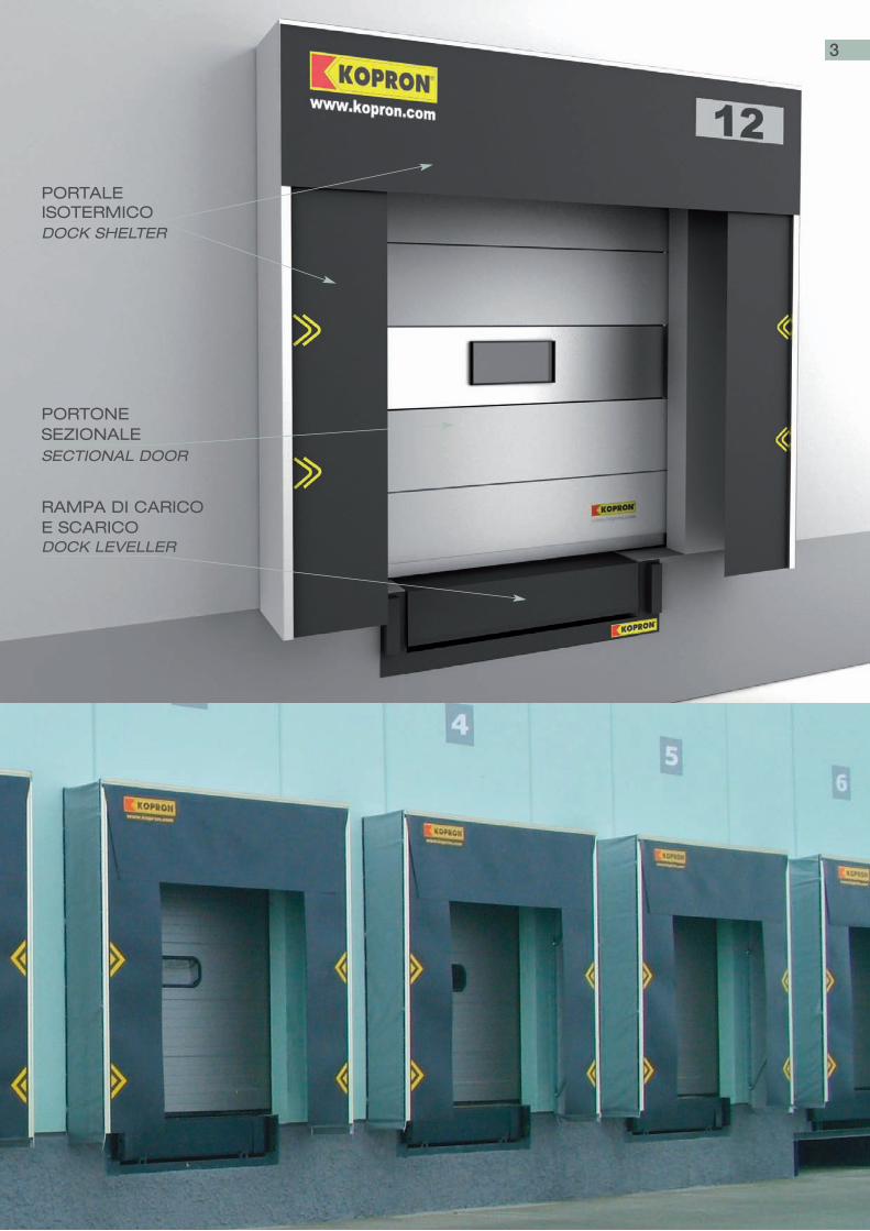
Attrezzature standardizzate progettate e realizzate per operare in si-curezza ed evitare costosi scambi termici durante le operazioni di mo-vimentazione delle merci tra gli automezzi e il magazzino. I portali iso-termici collegano la parte posteriore dell’automezzo con la parete delfabbricato.La struttura e tutti i sistemi vengono forniti con un dispositivo di as-sorbimento d’urti.
Standard equipment designed and manufactured to operate in safety avoid-ing expensive temperature variations inside the building when goods arehandled between vehicles and warehouse.Dock shelters allow the rear part of the vehicle to adhere to the walls of thebuilding and are provided with bumpers.
2
PORTALEISOTERMICODOCK SHELTER
PORTONESEZIONALESECTIONAL DOOR
RAMPA DI CARICOE SCARICODOCK LEVELLER
3
RAMPE DI CARICO/SCARICOLOADING/UNLOADING DOCK LEVELLERS
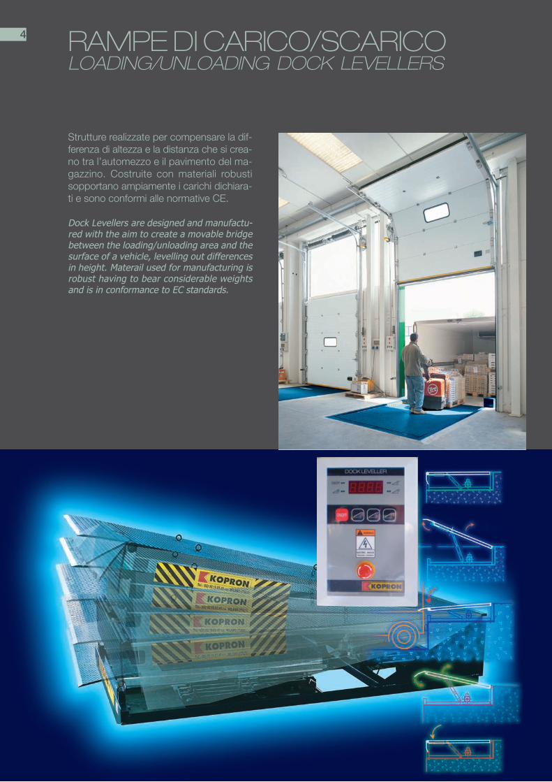
Strutture realizzate per compensare la dif-ferenza di altezza e la distanza che si crea-no tra l’automezzo e il pavimento del ma-gazzino. Costruite con materiali robustisopportano ampiamente i carichi dichiara-ti e sono conformi alle normative CE.
Dock Levellers are designed and manufactu-red with the aim to create a movable bridgebetween the loading/unloading area and thesurface of a vehicle, levelling out differencesin height. Materail used for manufacturing isrobust having to bear considerable weightsand is in conformance to EC standards.
4

TELAI - TIPOLOGIE
FRAME - TYPES
KRC I/T Cassaforma per automezzisenza sponda idraulica (pag. 8)KRC I/T Mould for vehicles without ahydraulic edge (page 8)
KRA I/T Telaio autoportante (pag. 9)
KRA I/T Frame for embedded version(page 9)
KRBM I/T Telaio Box model(page 11)
KRBM I/T Box Model (page 11)
KRP I/T Telaio Profilo (pag. 13)
Steel profile frame
KRCE I/TCassaforma Extrafossa per au-tomezzi con sponda idraulica.(pag.10)KRCE I/T High mould for vehicles withtailgates (page 10)
KRS I/T Telaio Sospeso per automezzicon o senza sponda idraulica (pag. 12)KRS I/T suspended frame
5

KRLI RAMPE ELETTRO-IDRAULICHECON LABBRO INCERNIERATOKRLI- ELECTRO-HYDRAULIC DOCK LEVELLERSWITH A SWINGING LIP
Rampa realizzata in modalità standard convarie dimensioni così come riassunte nellaseguente tabella.
This is the most widely used model of platform,and is produced in standard forms, in severalsizes summarized as follows.
HH
BB
LL
AA
A (larghezza) width 1.800 ÷ 2.200 mm
B (lunghezza) length 2.000 ÷ 4.500 mm
H (altezza) height 550 ÷ 800 mm
L (lunghezza labbro) lip length 400 mm
Escurs. pos./neg.pos./neg. excursion e÷12,5 %
6

KRLT RAMPE ELETTRO-IDRAULICHE CON LABBRO TELESCOPICOELECTRO-HYDRAULIC DOCK LEVELLERS WITH ATELESCOPIC LIP
HH
BB
LL
AA
A (larghezza) width 2.000 ÷ 2.200 mm
B (lunghezza) length 2.500 ÷ 3.000 mm
H (altezza) height 550 ÷ 800 mm
L (lunghezza labbro) lip length 1000 mm
Escurs. pos./neg.pos./neg. excursion ÷12,5 %
7
Rampe utilizzate nei casi di caricamento la-terale dell’automezzo o di carico posterio-re su container.Vengono prodotte in modalità standard convarie dimensioni così come descritte nellaseguente tabella.
These dock levellers are used mainly in situa-tions in which it is necessary to load the vehiclefrom the side.These are produced according to standardprocedures in several sizes summarized as fol-lows.
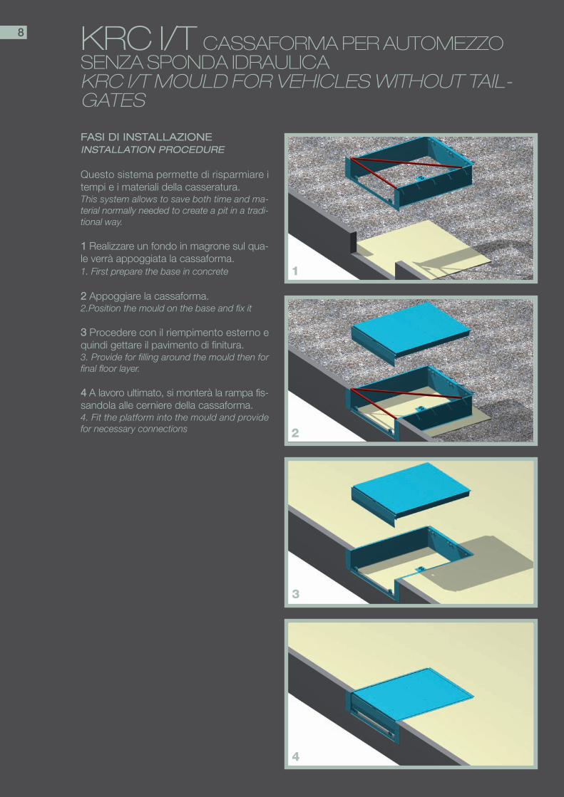
KRC I/T CASSAFORMA PER AUTOMEZZOSENZA SPONDA IDRAULICAKRC I/T MOULD FOR VEHICLES WITHOUT TAIL-GATES
FASI DI INSTALLAZIONEINSTALLATION PROCEDURE
Questo sistema permette di risparmiare itempi e i materiali della casseratura.This system allows to save both time and ma-terial normally needed to create a pit in a tradi-tional way.
11 Realizzare un fondo in magrone sul qua-le verrà appoggiata la cassaforma.1. First prepare the base in concrete
22 Appoggiare la cassaforma.2.Position the mould on the base and fix it
33 Procedere con il riempimento esterno equindi gettare il pavimento di finitura.3. Provide for filling around the mould then forfinal floor layer.
44 A lavoro ultimato, si monterà la rampa fis-sandola alle cerniere della cassaforma.4. Fit the platform into the mould and providefor necessary connections
1
8
2
3
4
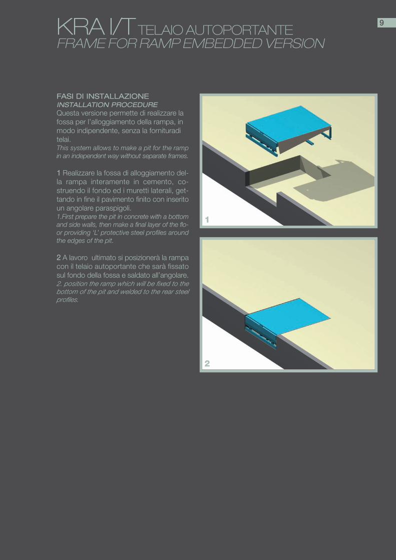
KRA I/T TELAIO AUTOPORTANTEFRAME FOR RAMP EMBEDDED VERSION
FASI DI INSTALLAZIONEINSTALLATION PROCEDUREQuesta versione permette di realizzare lafossa per l’alloggiamento della rampa, inmodo indipendente, senza la fornituraditelai.This system allows to make a pit for the rampin an independent way without separate frames.
11 Realizzare la fossa di alloggiamento del-la rampa interamente in cemento, co-struendo il fondo ed i muretti laterali, get-tando in fine il pavimento finito con inseritoun angolare paraspigoli.1.First prepare the pit in concrete with a bottomand side walls, then make a final layer of the flo-or providing ‘L’ protective steel profiles aroundthe edges of the pit.
22 A lavoro ultimato si posizionerà la rampacon il telaio autoportante che sarà fissatosul fondo della fossa e saldato all’angolare.2. position the ramp which will be fixed to thebottom of the pit and welded to the rear steelprofiles.
1
2
9

KRCE I/T CASSAFORMA EXTRAFOSSA PER AUTOMEZZI CON SPONDA IDRAULICA KRCE I/T HIGH MOULD FOR VEHICLES WITH TAIL-GATES
FASI DI INSTALLAZIONEINSTALLATION PROCEDURE
Questo sistema permette di risparmiare itempi e i materiali della casseratura e direalizzare il vano inferiore per l’alloggia-mento della sponda idraulica di carico de-gli automezzi.This system allows to save both time andmaterial normally needed when creating ina traditional way a pit and a box hosting thelorry tailgate.
11 Realizzare un fondo in magrone sul qua-le verrà appoggiata la cassaforma.1. First prepare the base in concrete for po-stioning the mould.
22 Realizzare chiusure vano porta pannello.2. Seal the two front gaps between thebottom and upper part of the mould.
33 Procedere con il riempimento esterno equindi gettare il pavimento di finitura.3. Provide for filling around the mould thenfor final floor layer.
44 A lavoro ultimato, si monterà la rampa fis-sandola alle cerniere della cassaforma.4. Fit the platform into the mould
1
2
3
4
10
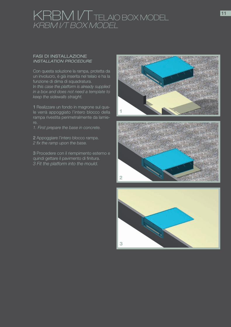
KRBM I/T TELAIO BOX MODELKRBM I/T BOX MODEL
FASI DI INSTALLAZIONEINSTALLATION PROCEDURE
Con questa soluzione la rampa, protetta daun involucro, è già inserita nel telaio e ha lafunzione di dima di squadratura.In this case the platform is already suppliedin a box and does not need a template tokeep the sidewalls straight.
11 Realizzare un fondo in magrone sul qua-le verrà appoggiato l’intero blocco dellarampa rivestita perimetralmente da lamie-re.1. First prepare the base in concrete.
22 Appoggiare l’intero blocco rampa.2 fix the ramp upon the base.
33 Procedere con il riempimento esterno equindi gettare il pavimento di finitura.3 Fit the platform into the mould.
1
2
3
11
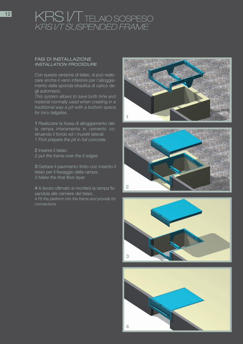
KRS I/T TELAIO SOSPESOKRS I/T SUSPENDED FRAME
FASI DI INSTALLAZIONEINSTALLATION PROCEDURE
Con questa versione di telaio, si può realiz-zare anche il vano inferiore per l’alloggia-mento della sponda idraulica di carico de-gli automezzi.This system allows to save both time andmaterial normally used when creating in atraditional way a pit with a bottom spacefor lorry tailgates.
11 Realizzare la fossa di alloggiamento del-la rampa interamente in cemento co-struendo il fondo ed i muretti laterali.1 First prepare the pit in full concrete.
22 Inserire il telaio.2 put the frame over the it edges
33 Gettare il pavimento finito con inserito iltelaio per il fissaggio della rampa.3 Make the final floor layer
44 A lavoro ultimato si monterà la rampa fis-sandola alle cerniere del telaio.4 Fit the platform into the frame and provide forconnections
1
2
3
4
12

KRP I/T TELAIO PROFILOKRP I/T STEEL PROFILE FRAME
FASI DI INSTALLAZIONEINSTALLATION PROCEDURE
In questa soluzione l’angolare paraspigolicompleto di cerniere viene fornito diretta-mente da Kopron.For this solution the peripheral protectivesteel profiles of the edges of the pit aresupplied.
11 Realizzare la fossa di alloggiamento del-la rampa interamente in cemento co-struendo il fondo ed i muretti laterali.1 First prepare the pit in full concrete.
22 Inserire il telaio.2 Put the frame over the pit edges
33 Gettare il pavimento finito con inserito iltelaio per il fissaggio della rampa.3 make the final floor layer
44 A lavoro ultimato si monterà la rampa fis-sandola alle cerniere del telaio.4 Fit the platform into the frame and provi-de for connections
1
2
3
4
13
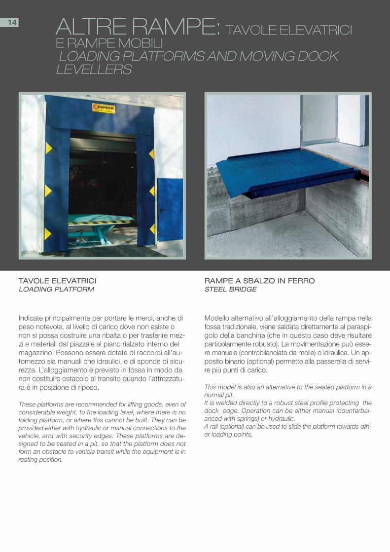
ALTRE RAMPE: TAVOLE ELEVATRICI E RAMPE MOBILILOADING PLATFORMS AND MOVING DOCK
LEVELLERS
Modello alternativo all’alloggiamento della rampa nellafossa tradizionale, viene saldata direttamente al paraspi-golo della banchina (che in questo caso deve risultareparticolarmente robusto). La movimentazione può esse-re manuale (controbilanciata da molle) o idraulica. Un ap-posito binario (optional) permette alla passerella di servi-re più punti di carico.
This model is also an alternative to the seated platform in anormal pit.It is welded directly to a robust steel profile protecting thedock edge. Operation can be either manual (counterbal-anced with springs) or hydraulic.A rail (optional) can be used to slide the platform towards oth-er loading points.
Indicate principalmente per portare le merci, anche dipeso notevole, al livello di carico dove non esiste onon si possa costruire una ribalta o per trasferire mez-zi e materiali dal piazzale al piano rialzato interno delmagazzino. Possono essere dotate di raccordi all’au-tomezzo sia manuali che idraulici, e di sponde di sicu-rezza. L’alloggiamento è previsto in fossa in modo danon costituire ostacolo al transito quando l’attrezzatu-ra è in posizione di riposo.
These platforms are recommended for lifting goods, even ofconsiderable weight, to the loading level, where there is nofolding platform, or where this cannot be built. They can beprovided either with hydraulic or manual connections to thevehicle, and with security edges. These platforms are de-signed to be seated in a pit, so that the platform does notform an obstacle to vehicle transit while the equipment is inresting position.
TAVOLE ELEVATRICI LOADING PLATFORM
RAMPE A SBALZO IN FERRO STEEL BRIDGE
14
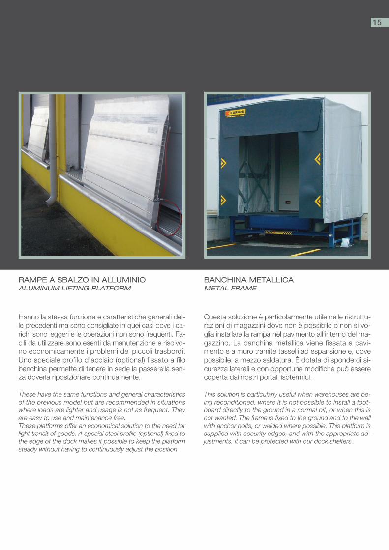
Questa soluzione è particolarmente utile nelle ristruttu-razioni di magazzini dove non è possibile o non si vo-glia installare la rampa nel pavimento all’interno del ma-gazzino. La banchina metallica viene fissata a pavi-mento e a muro tramite tasselli ad espansione e, dovepossibile, a mezzo saldatura. È dotata di sponde di si-curezza laterali e con opportune modifiche può esserecoperta dai nostri portali isotermici.
This solution is particularly useful when warehouses are be-ing reconditioned, where it is not possible to install a foot-board directly to the ground in a normal pit, or when this isnot wanted. The frame is fixed to the ground and to the wallwith anchor bolts, or welded where possible. This platform issupplied with security edges, and with the appropriate ad-justments, it can be protected with our dock shelters.
Hanno la stessa funzione e caratteristiche generali del-le precedenti ma sono consigliate in quei casi dove i ca-richi sono leggeri e le operazioni non sono frequenti. Fa-cili da utilizzare sono esenti da manutenzione e risolvo-no economicamente i problemi dei piccoli trasbordi.Uno speciale profilo d’acciaio (optional) fissato a filobanchina permette di tenere in sede la passerella sen-za doverla riposizionare continuamente.
These have the same functions and general characteristicsof the previous model but are recommended in situationswhere loads are lighter and usage is not as frequent. Theyare easy to use and maintenance free.These platforms offer an economical solution to the need forlight transit of goods. A special steel profile (optional) fixed tothe edge of the dock makes it possible to keep the platformsteady without having to continuously adjust the position.
BANCHINA METALLICAMETAL FRAME
RAMPE A SBALZO IN ALLUMINIOALUMINUM LIFTING PLATFORM
15
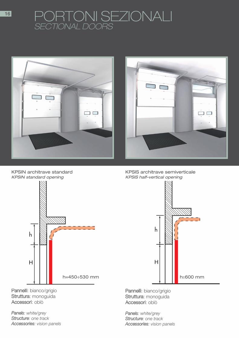
PORTONI SEZIONALI SECTIONAL DOORS
PPaannnneellllii: bianco/grigioSSttrruuttttuurraa: monoguidaAAcccceessssoorrii: oblò
PPaanneellss: white/greySSttrruuccttuurree: one trackAAcccceessssoorriieess: vision panels
h
H
PPaannnneellllii: bianco/grigioSSttrruuttttuurraa: monoguidaAAcccceessssoorrii: oblò
PPaanneellss: white/greySSttrruuccttuurree: one trackAAcccceessssoorriieess: vision panels
h
H
KPSIN architrave standardKPSIN standard opening
KPSIS architrave semiverticaleKPSIS half-vertical opening
h=450÷530 mm h≥600 mm
16
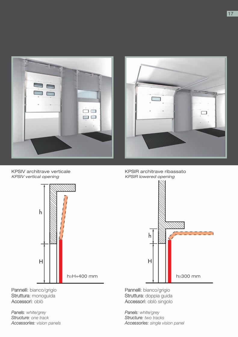
PPaannnneellllii: bianco/grigioSSttrruuttttuurraa: doppia guidaAAcccceessssoorrii: oblò singolo
PPaanneellss: white/greySSttrruuccttuurree: two tracksAAcccceessssoorriieess: single vision panel
PPaannnneellllii: bianco/grigioSSttrruuttttuurraa: monoguidaAAcccceessssoorrii: oblò
PPaanneellss: white/greySSttrruuccttuurree: one trackAAcccceessssoorriieess: vision panels
h
H
h
H
KPSIR architrave ribassatoKPSIR lowered opening
KPSIV architrave verticaleKPSIV vertical opening
h≥H+400 mm h≥300 mm
17
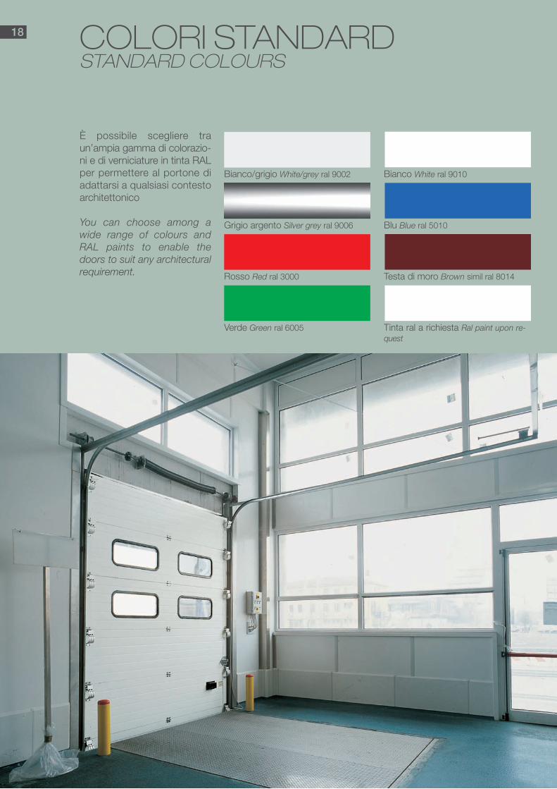
COLORI STANDARDSTANDARD COLOURS
Bianco/grigio White/grey ral 9002
Verde Green ral 6005
Rosso Red ral 3000
Grigio argento Silver grey ral 9006
Bianco White ral 9010
Tinta ral a richiesta Ral paint upon re-quest
Testa di moro Brown simil ral 8014
Blu Blue ral 5010
È possibile scegliere traun’ampia gamma di colorazio-ni e di verniciature in tinta RALper permettere al portone diadattarsi a qualsiasi contestoarchitettonico
You can choose among awide range of colours andRAL paints to enable thedoors to suit any architecturalrequirement.
18
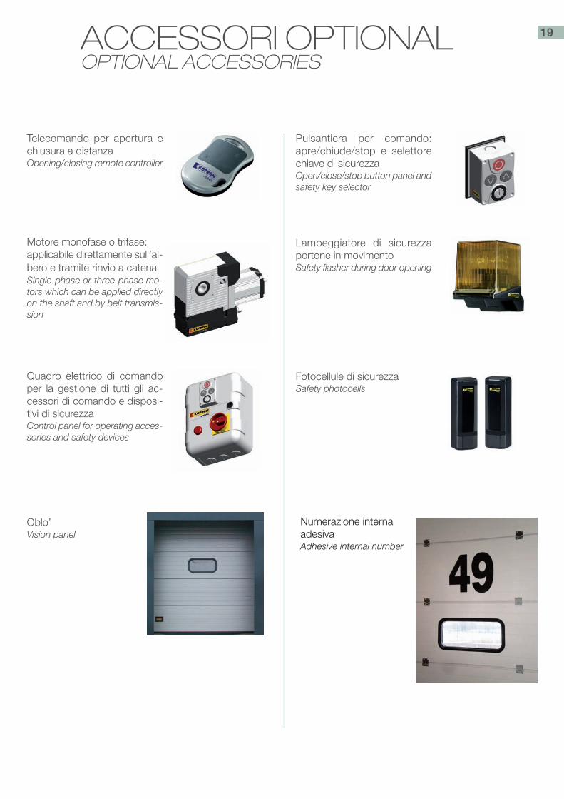
Motore monofase o trifase: applicabile direttamente sull’al-bero e tramite rinvio a catenaSingle-phase or three-phase mo-tors which can be applied directlyon the shaft and by belt transmis-sion
Telecomando per apertura echiusura a distanzaOpening/closing remote controller
Pulsantiera per comando:apre/chiude/stop e selettorechiave di sicurezzaOpen/close/stop button panel andsafety key selector
Lampeggiatore di sicurezzaportone in movimentoSafety flasher during door opening
Fotocellule di sicurezzaSafety photocells
Quadro elettrico di comandoper la gestione di tutti gli ac-cessori di comando e disposi-tivi di sicurezzaControl panel for operating acces-sories and safety devices
Oblo’Vision panel
Numerazione interna adesivaAdhesive internal number
ACCESSORI OPTIONALOPTIONAL ACCESSORIES
19
PORTALI ISOTERMICIDOCK SHELTERS
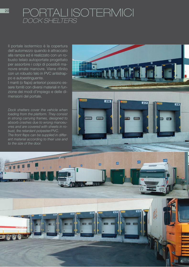
Il portale isotermico è la coperturadell’automezzo quando è attraccatoalla rampa ed è realizzato con un ro-busto telaio autoportate progettatoper assorbire i colpi di possibili ma-novre errate manovre. Viene rifinitocon un robusto telo in PVC antistrap-po e autoestinguente.I manti (o flaps) anteriori possono es-sere forniti con diversi materiali in fun-zione dei modi d’impiego e delle di-mensioni del portale.
Dock shelters cover the vehicle whenloading from the platform. They consistin strong carrying frames, designed toabsorb crashes due to wrong manoeu-vres and are covered with sheets in ro-bust, fire retardant polyester/PVC.The front flaps can be supplied in differ-ent material according to their use andto the size of the door.
20
PORTALI ISOTERMICI TIPOLOGIEDOCK SHELTERS - MODELS
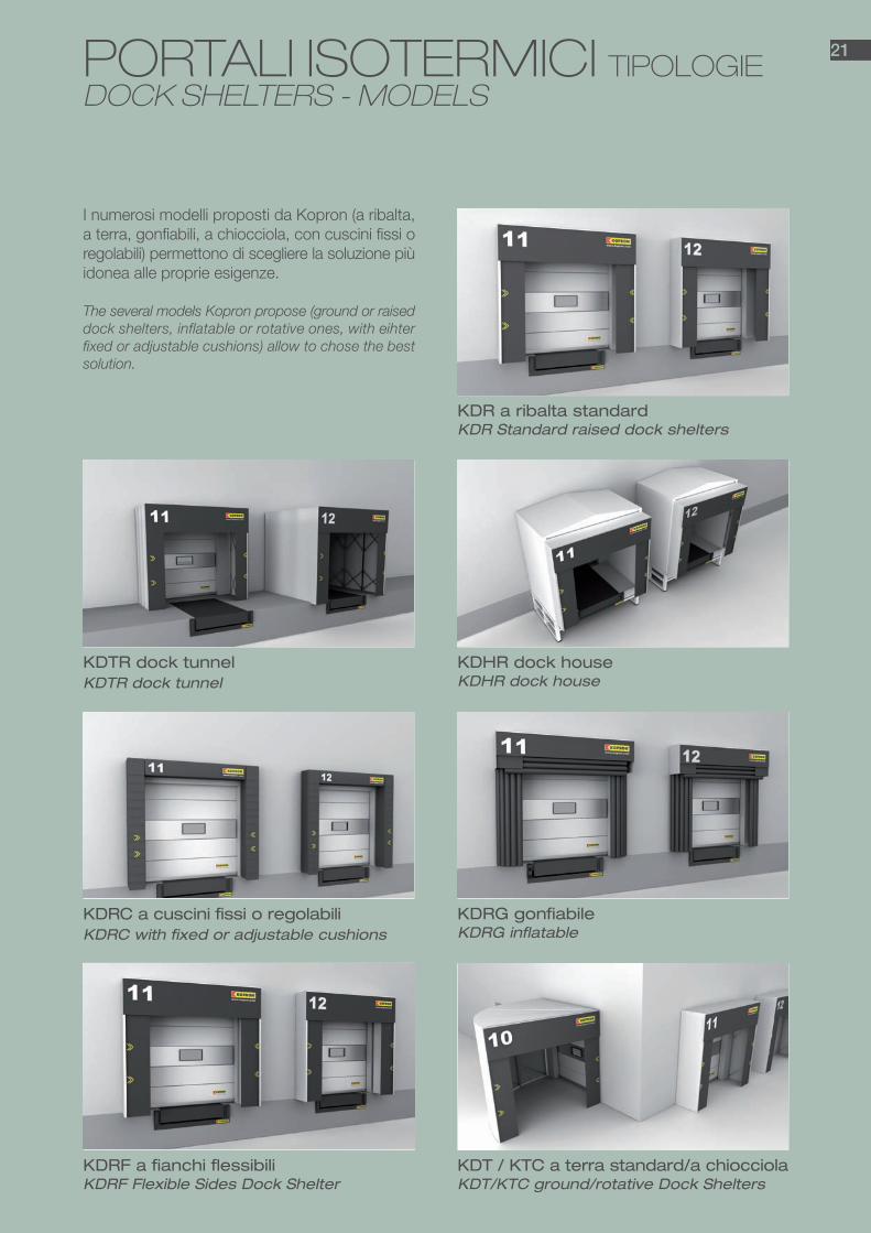
KDR a ribalta standardKDR Standard raised dock shelters
KDHR dock houseKDHR dock house
KDTR dock tunnelKDTR dock tunnel
KDRG gonfiabileKDRG inflatable
KDRC a cuscini fissi o regolabili KDRC with fixed or adjustable cushions
KDT / KTC a terra standard/a chiocciolaKDT/KTC ground/rotative Dock Shelters
KDRF a fianchi flessibiliKDRF Flexible Sides Dock Shelter
21
I numerosi modelli proposti da Kopron (a ribalta,a terra, gonfiabili, a chiocciola, con cuscini fissi oregolabili) permettono di scegliere la soluzione piùidonea alle proprie esigenze.
The several models Kopron propose (ground or raiseddock shelters, inflatable or rotative ones, with eihterfixed or adjustable cushions) allow to chose the bestsolution.

KDR A RIBALTA STANDARDKDR RAISED DOCK SHELTERS
Costruiti in due diverse soluzioni per soddisfare ogni esigenza dilimitazione degli scambi termici tra l’interno e l’esterno del ma-gazzino, contribuiscono al risparmio energetico ed al migliora-mento del livello di comfort del personale addetto.Il modello base, KDR S, è stato progettato per soddisfare esi-genze di carattere generale e unisce un’ottima funzionalità ad uncosto decisamente contenuto.Il modello a pantografo KDR P, oltre ad essere costruito su mi-sura per adeguarsi ad esigenze particolari (vani di carico non stan-dardizzati, strutture architettoniche particolari), può essere forni-to anche con colorazioni diverse in modo da inserirsi ancor me-glio in qualsiasi ambiente.
This model is proposed in two different configurations and is ideal toavoid heat exchange between the inside of the warehouse and the out-side, besides improving comfort of personnel and saving energy.Basic model KDR S, is designed to satisfy general requirements andcombines excellent functionality with contained costs.The pantograph model KDR P can be built according toCustomer’s specific needs (like suiting non-standard loading spaces orparticular architectural structures) and may be supplied in differentcolours to match with the architectural environment.
®
®
22
KDR S
KDR P

23

KDTR DOCK TUNNEL KDTR DOCK TUNNEL
Il portale isotermico a tunnel da banchina svolge le stes-se funzioni dei portali KDR precedentementeillustrati ma sono concepiti per il raccordo diretto tra il ma-gazzino e l’automezzo in presenza di banchinadi carico sporgente oltre l’edificio sia con rampa incor-porata che senza; di conseguenza, pur mantenendo ledimensioni frontali (altezza e larghezza) simili al modelloKDR, la profondità è in funzione dellasporgenza della banchina.Sono disponibili anche modelli speciali per banchine an-golate o dotate di passerelle di raccordo agganciate albordo della banchina stessa.
The dock tunnel for loading bays has the same function as thepreviously illustrated KDR dock shelters, but are designed fordirectly connecting the warehouse to thevehicle in the presence of a loading bay which stretches outbeyond the building. This dock tunnel although keeping samefrontal sizes (in height and width) as the KDR Model, may belongher by stretching out to tincorporate the dock leveller.There are also special models available for angle docks or withmanual ramps built onto the edge of the dock itself.
®
24

KDHR DOCK HOUSEKDHR DOCK HOUSE
Montato a copertura e sigillatura di un vano con portonedi chiusura, viene posizionato sopra una banchina esi-stente in cemento o ferro.È costituito da struttura portante in archi di acciaio zin-cato a caldo che poggiano su banchina, e collegati tra lo-ro da traversi fissi che consentono l’estensione fino allaparte posteriore dell’automezzo. Il rivestimento è ottenu-to con pannelli sandwich coibentati.
This model is used to cover and seal loading doors, and is po-sitioned over an existing loading bay in cement or steel.it consists of a hot galvanized steel frame covered by sandwichpanels with a length that provides covering the rear part of thelorries during loading/unloading operations.
25

KDRC A CUSCINI FISSI O REGOLABILI KDRC FIXED OR ADJUSTABLE CUSHION DOCKSHELTER
Adatto a tamponare bocche di carico di magazzini a bas-sa temperatura. È fornibile in versione fissa (KDRC F), uti-lizzabile per automezzi rientranti nella stessa gamma di-mensionale, ed in versione regolabile (KDRC R) con iltampone superiore mobile adattabile alle varie altezze de-gli automezzi. La sigillatura è ottenuta premendo sui cu-scini imbottiti di poliuretano a cellule chiuse e rivestiti daun robusto telo di poliestere/PVC. A differenza degli altriportali isotermici per basse temperature, il modello KDRCtrasmette in parte la spinta dell’automezzo alle strutturedel magazzino che andranno opportunamente rinforzatesu nostra indicazione.
This dock shelter, like the previous one, is suitable for shelter-ing loading doors of warehouses where low temperatures mustbe kept. They can be supplied either in a fixed version (KDCF), for vehicles always of same size, or in an adjustable version(KDC R) for vehicles of different heights. Similar to other mod-els, the sealing is obtained through closed cell polyurethanecushions pressing against the vehicle, covered with a robustPVC /polyester sheet. Unlike other models, this dock sheltertransmits vehicle drive force to the warehouse structure, whichwill have to be properly reinforced according to our instructions.
26
KDRC F
KDRC R

KDRG GONFIABILEKDRG INFLATABLE
Particolarmente indicato per la sigillatura di bocche di ca-rico di magazzini frigoriferi a bassa temperatura, in quan-to i cuscini gonfiabili aderiscono perfettamente alla sago-ma dell’automezzo sotto carico, impedendo così costo-si scambi termici tra il magazzino e l’esterno. Questo por-tale si adatta ad una vasta gamma dimensionale di auto-mezzi e non trasmette la spinta dell’automezzo sotto ca-rico alle strutture del magazzino.
This model is ideal for sealing loading doors of low-tempera-ture refrigerated warehouses, since the inflatablecushions adhere perfectly to vehicle frames, which can be ofvarious sizes, and avoid costly loss of temperature.This dock shelter does not transmit the drive force of the ve-hicle to the warehouse structure.
®®
27

28 KDRF A FIANCHI FLESSIBILIKDRF FLEXIBLE SIDES DOCK SHELTER
Questo portale ben si adatta alla sigillatura di bocche dicarico su magazzini a bassa temperatura.La sigillatura è ottenuta premendo con l’automezzo suicuscini imbottiti di poliuretano a cellule chiuse erivestiti di un robusto telo di poliestere/PVC confezionatocon apposite tegole anti-usure che limitanoil danno da pressione e sfregamento prodotto dall’auto-mezzo sotto carico.Questo portale non trasmette la spinta dell’automezzosotto carico alle strutture del magazzino
This dock shelter is ideal for sheltering loading doors of ware-houses where low temperatures must be kept.The sealing is obtained through closed cell polyurethane cush-ions pressing against the vehicle, covered with a robust PVC/polyester and packed with anti-wear flaps which limit dam-ages caused by friction and pressure of the vehicle duringi load-ing operations.This dock shelter does not transmit the drive force of the ve-hicle to the warehouse structure.
®®

®
®
KDT / KTC A TERRA STANDARD /A CHIOCCIOLA KDT/KTC GROUND-LEVEL/ROTATIVE DOCKSHELTER
Il portale isotermico a terra è indicato per la sigillatura divani di carico a piano piazzale, dotati o meno di tavola ele-vatrice, con spazi per la manovra ridotti che necessitanodi rimuovere la struttura per permettere il passaggio degliautomezzi.Se il punto di carico è dotato di tavola elevatrice esterna,il portale può essere costruito con lunghezza tale da con-tenere questa attrezzatura, consentendo l’utilizzo in qual-siasi condizione atmosferica.Il modello KTC “a chiocciola” è adatto a proteggere le ope-razioni di carico e scarico in zone ristrette tra il magazzinoe il confine dove l’attracco dell’automezzo è parallelo e nonperpendicolare al fabbricato. L’orientamento è destro o si-nistro e l’angolo di apertura va da 0 a 90 °.
This ground-level dock shelter, is suitable for sealing loadingareas at vehicle level, with or without a loading platform, whichhave little space for manoeuvring and where the structure wouldhave to be removed to allow the transit of vehicles.Should loading points have an external elevator platform, thedock shelter can be made in order to cover all the equiipmentprotecting it from weather conditions.The KTC rotative model is particularly ideal in case truckscannot load/unload perpendicularly due to the narrowspace between warehouse and truck parking space. Thedock shelter can rotate either towards right or left from 0°to 90°.
®
29
KDT P/S
KDT S
KTC

ACCESSORI ACCESSORIES
EASY-LINEEASY-LINE
TAMPONI FISSI E REGOLABILI FIXED AND ADJUSTABLE RUBBER BUMPERS.
SISTEMA K1 BLOCK PER IL BLOCCAGGIO DELLE RUOTE DELL’AUTOMEZZOK1 BLOCK SYSTEM, FOR BLOCKING VEHICLE WHEELS.
NUMERAZIONE E SEGNALETICA SU RICHIESTA SPECIFICA DEL CLIENTE NUMBERS AND SIGNALS UPON SPECIFIC REQUEST OF THE CUSTOMER
30

SEMAFORI TRAFFIC LIGHTS
INTERCONNESSIONE RAMPA-PORTONE
DOCK LEVELLER-DOOR CONNECTING SENSOR
CANALINA GENERICA COPRICAVI
CABLE CASING
FOTOCELLULEPHOTOCELLS
LABBRO FRAZIONATO CON FLAPLIP WITH SIDE FLAPS
CUNEI CON SENSORE DI BLOCCAGGIO RUOTEWEDGES TO STOP TRUCK WHEELS IN LOADING AND UNLOADING POSITION
COLONNINA PORTAQUADRO ELETTRICO
CONTROL PANEL SUPPORTING POST
31
il Kopron team sport
ww
w.k
op
ro
n.c
om
Kopron SpAVia I Maggio20064 Gorgonzola (MI) Italyt +39 02 921521f +39 02 92152920
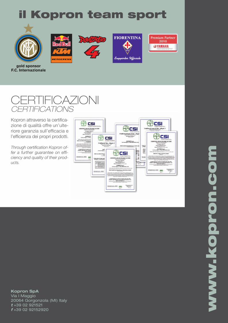
CERTIFICAZIONICERTIFICATIONSKopron attraverso la certifica-zione di qualità offre un’ulte-riore garanzia sull’efficacia el’efficienza dei propri prodotti.
Through certification Kopron of-fer a further guarantee on effi-ciency and quality of their prod-ucts.