
RX - riellobrulor.com.tr · errore e/o un’anomalia; ... sime alle quali il bruciatore è...
60
Istruzioni per installazione, uso e manutenzione Installation, use and maintenance instructions 20046745 (2) - 04/2012 Bruciatori di gas premiscelato Premixed gas burners Funzionamento bistadio progressivo o modulante Progressive two-stage or modulating operation CODICE - CODE MODELLO - MODEL TIPO - TYPE 20043317 RX 400 S/PV 909T1 20046819 RX 550 S/PV 910T1 I GB RX
-
Upload
truongkiet -
Category
Documents
-
view
212 -
download
0
Transcript of RX - riellobrulor.com.tr · errore e/o un’anomalia; ... sime alle quali il bruciatore è...
Istruzioni per installazione, uso e manutenzioneInstallation, use and maintenance instructions
20046745 (2) - 04/2012
Bruciatori di gas premiscelato
Premixed gas burners
Funzionamento bistadio progressivo o modulanteProgressive two-stage or modulating operation
CODICE - CODE MODELLO - MODEL TIPO - TYPE
20043317 RX 400 S/PV 909T1
20046819 RX 550 S/PV 910T1
I
GB
RX

Istruzioni originaliTranslation of the original instructions
1 20046745I
Indice
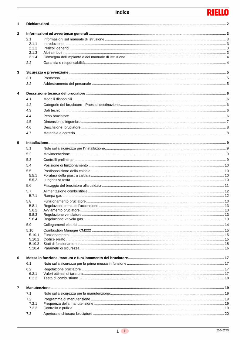
1 Dichiarazioni ............................................................................................................................................................................... 2
2 Informazioni ed avvertenze generali ........................................................................................................................................ 3
2.1 Informazioni sul manuale di istruzione ........................................................................................................................ 32.1.1 Introduzione................................................................................................................................................................. 32.1.2 Pericoli generici ........................................................................................................................................................... 32.1.3 Altri simboli .................................................................................................................................................................. 32.1.4 Consegna dell’impianto e del manuale di istruzione ................................................................................................... 4
2.2 Garanzia e responsabilità............................................................................................................................................ 4
3 Sicurezza e prevenzione............................................................................................................................................................ 5
3.1 Premessa .................................................................................................................................................................... 5
3.2 Addestramento del personale ..................................................................................................................................... 5
4 Descrizione tecnica del bruciatore ........................................................................................................................................... 6
4.1 Modelli disponibili ........................................................................................................................................................ 6
4.2 Categorie del bruciatore - Paesi di destinazione......................................................................................................... 6
4.3 Dati tecnici................................................................................................................................................................... 6
4.4 Peso bruciatore ........................................................................................................................................................... 6
4.5 Dimensioni d’ingombro................................................................................................................................................ 7
4.6 Descrizione bruciatore................................................................................................................................................ 8
4.7 Materiale a corredo ..................................................................................................................................................... 8
5 Installazione................................................................................................................................................................................ 9
5.1 Note sulla sicurezza per l’installazione........................................................................................................................ 9
5.2 Movimentazione .......................................................................................................................................................... 9
5.3 Controlli preliminari...................................................................................................................................................... 9
5.4 Posizione di funzionamento ...................................................................................................................................... 10
5.5 Predisposizione della caldaia .................................................................................................................................... 105.5.1 Foratura della piastra caldaia .................................................................................................................................... 105.5.2 Lunghezza testa ........................................................................................................................................................ 10
5.6 Fissaggio del bruciatore alla caldaia ......................................................................................................................... 11
5.7 Alimentazione combustibile....................................................................................................................................... 125.7.1 Rampa gas ................................................................................................................................................................ 12
5.8 Funzionamento bruciatore......................................................................................................................................... 135.8.1 Regolazioni prima dell’accensione ............................................................................................................................ 135.8.2 Avviamento bruciatore............................................................................................................................................... 135.8.3 Regolazione ventilatore............................................................................................................................................. 135.8.4 Regolazione valvola gas ........................................................................................................................................... 13
5.9 Collegamenti elettrici ................................................................................................................................................. 14
5.10 Combustion Manager CM222 ................................................................................................................................... 155.10.1 Funzionamento.......................................................................................................................................................... 155.10.2 Codice errato............................................................................................................................................................. 155.10.3 Stati di funzionamento............................................................................................................................................... 155.10.4 Parametri di sicurezza............................................................................................................................................... 16
6 Messa in funzione, taratura e funzionamento del bruciatore............................................................................................... 17
6.1 Note sulla sicurezza per la prima messa in funzione ................................................................................................ 17
6.2 Regolazione bruciatore ............................................................................................................................................. 176.2.1 Valori ottimali di taratura............................................................................................................................................ 176.2.2 Testa di combustione ................................................................................................................................................ 18
7 Manutenzione ........................................................................................................................................................................... 19
7.1 Note sulla sicurezza per la manutenzione................................................................................................................. 19
7.2 Programma di manutenzione .................................................................................................................................... 197.2.1 Frequenza della manutenzione ................................................................................................................................. 197.2.2 Controllo e pulizia...................................................................................................................................................... 19
7.3 Apertura e chiusura bruciatore .................................................................................................................................. 20
20046745 2 I
Indice
8 Appendice - Accessori .............................................................................................................................................................21
9 Appendice - Schema quadro elettrico.....................................................................................................................................22
3 20046745I
Dichiarazioni
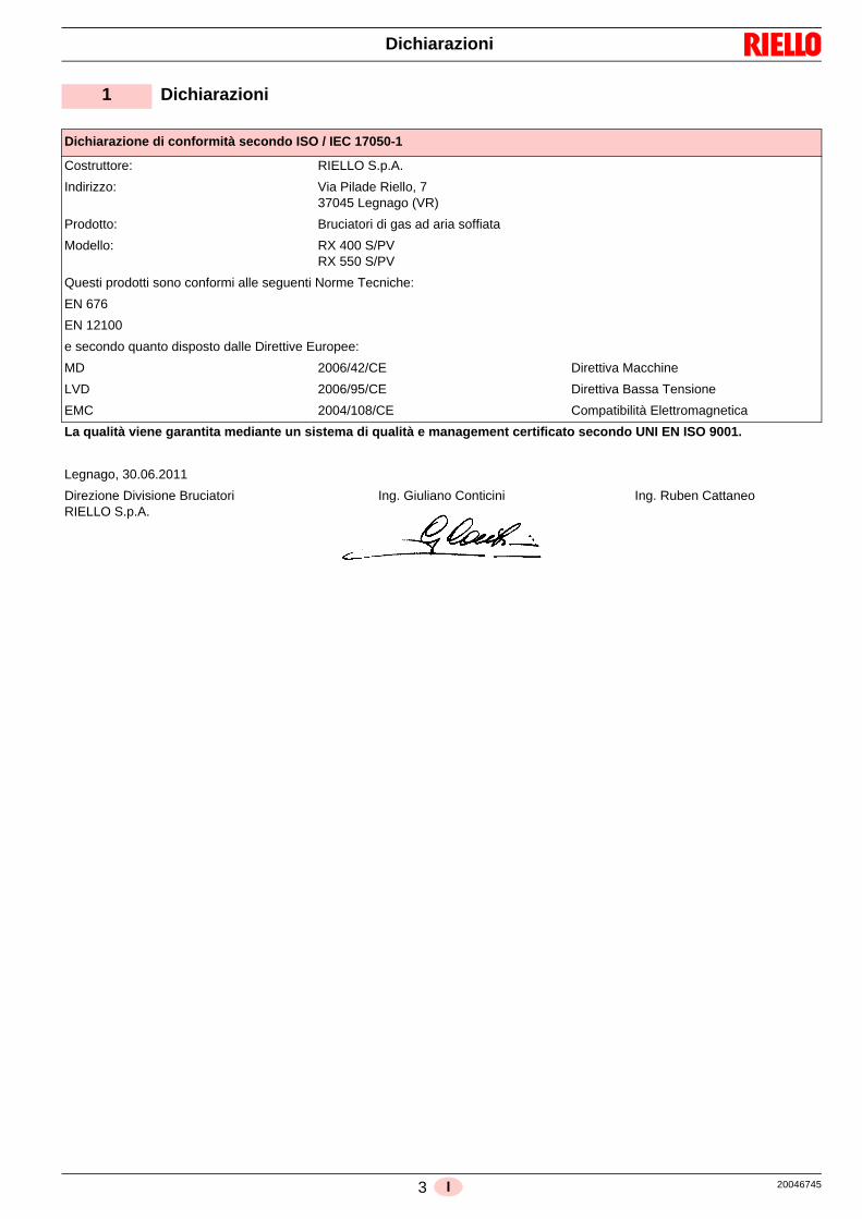
1 Dichiarazioni
Dichiarazione di conformità secondo ISO / IEC 17050-1
Costruttore: RIELLO S.p.A.
Indirizzo: Via Pilade Riello, 737045 Legnago (VR)
Prodotto: Bruciatori di gas ad aria soffiata
Modello: RX 400 S/PVRX 550 S/PV
Questi prodotti sono conformi alle seguenti Norme Tecniche:
EN 676
EN 12100
e secondo quanto disposto dalle Direttive Europee:
MD 2006/42/CE Direttiva Macchine
LVD 2006/95/CE Direttiva Bassa Tensione
EMC 2004/108/CE Compatibilità Elettromagnetica
La qualità viene garantita mediante un sistema di qualità e management certificato secondo UNI EN ISO 9001.
Legnago, 30.06.2011
Direzione Divisione BruciatoriRIELLO S.p.A.
Ing. Giuliano Conticini Ing. Ruben Cattaneo
20046745 4 I
Informazioni ed avvertenze generali
2.1 Informazioni sul manuale di istruzione
2.1.1 Introduzione
Il manuale di istruzione dato a corredo del bruciatore: costituisce parte integrante ed essenziale del prodotto e non
va da esso separato; deve essere quindi conservato concura per ogni necessaria consultazione e deve accompa-gnare il bruciatore anche in caso di cessione ad un altro pro-prietario o utente, oppure in caso di trasferimento su un altroimpianto. In caso di danneggiamento o smarrimento deveessere richiesto un altro esemplare al Servizio Tecnico diAssistenza di Zona;
è stato realizzato per un utilizzo da parte di personale qualifi-cato;
fornisce importanti indicazioni ed avvertenze sulla sicurezzanell’installazione, la messa in funzione, l’uso e la manuten-zione del bruciatore.
Simbologia utilizzata nel manuale
In alcune parti del manuale sono riportati segnali triangolari diPERICOLO. Prestare ad essi molta attenzione, in quanto segna-lano una situazione di potenziale pericolo.
2.1.2 Pericoli generici
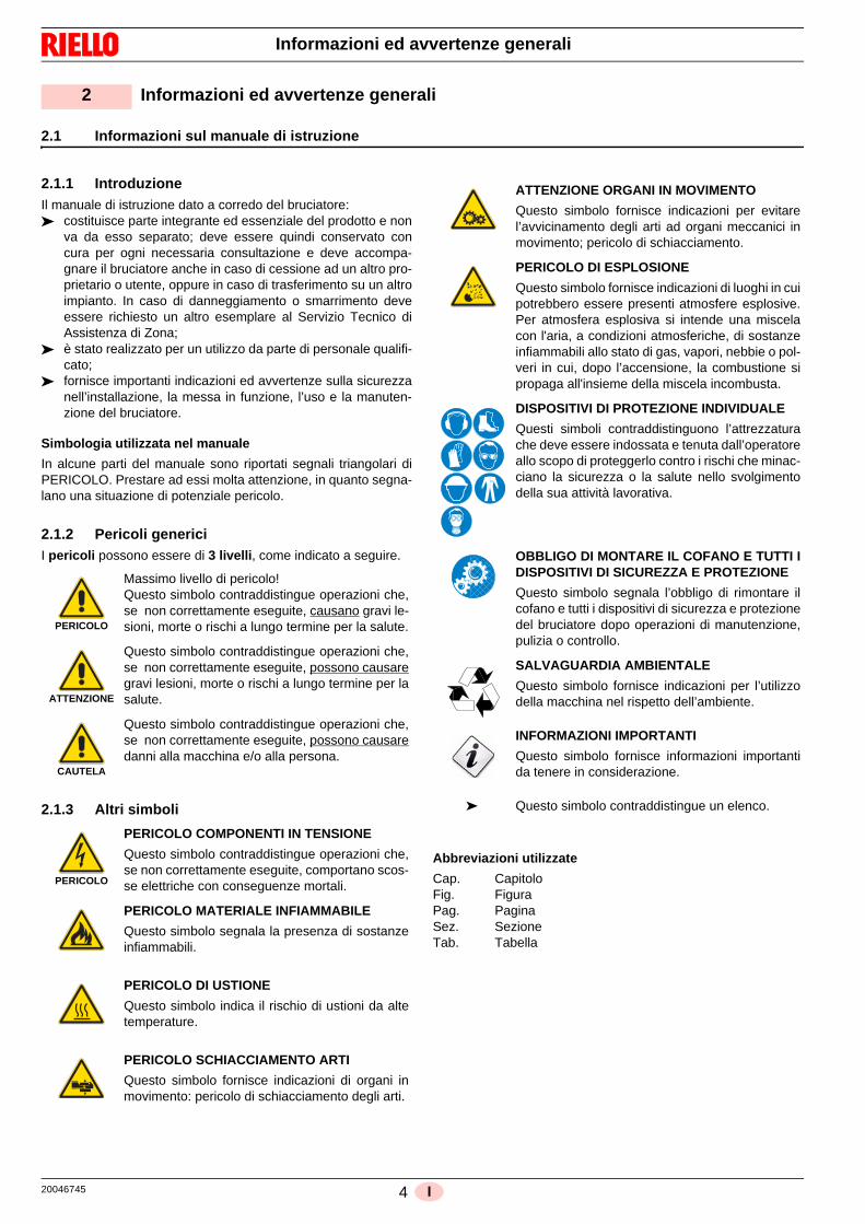
I pericoli possono essere di 3 livelli, come indicato a seguire.
2.1.3 Altri simboli
Abbreviazioni utilizzate
Cap. CapitoloFig. FiguraPag. PaginaSez. SezioneTab. Tabella
2 Informazioni ed avvertenze generali
PERICOLO
Massimo livello di pericolo!Questo simbolo contraddistingue operazioni che,se non correttamente eseguite, causano gravi le-sioni, morte o rischi a lungo termine per la salute.
ATTENZIONE
Questo simbolo contraddistingue operazioni che,se non correttamente eseguite, possono causaregravi lesioni, morte o rischi a lungo termine per lasalute.
CAUTELA
Questo simbolo contraddistingue operazioni che,se non correttamente eseguite, possono causaredanni alla macchina e/o alla persona.
PERICOLO
PERICOLO COMPONENTI IN TENSIONE
Questo simbolo contraddistingue operazioni che,se non correttamente eseguite, comportano scos-se elettriche con conseguenze mortali.
PERICOLO MATERIALE INFIAMMABILE
Questo simbolo segnala la presenza di sostanzeinfiammabili.
PERICOLO DI USTIONE
Questo simbolo indica il rischio di ustioni da altetemperature.
PERICOLO SCHIACCIAMENTO ARTI
Questo simbolo fornisce indicazioni di organi inmovimento: pericolo di schiacciamento degli arti.
ATTENZIONE ORGANI IN MOVIMENTO
Questo simbolo fornisce indicazioni per evitarel’avvicinamento degli arti ad organi meccanici inmovimento; pericolo di schiacciamento.
PERICOLO DI ESPLOSIONE
Questo simbolo fornisce indicazioni di luoghi in cuipotrebbero essere presenti atmosfere esplosive.Per atmosfera esplosiva si intende una miscelacon l'aria, a condizioni atmosferiche, di sostanzeinfiammabili allo stato di gas, vapori, nebbie o pol-veri in cui, dopo l’accensione, la combustione sipropaga all'insieme della miscela incombusta.
DISPOSITIVI DI PROTEZIONE INDIVIDUALE
Questi simboli contraddistinguono l’attrezzaturache deve essere indossata e tenuta dall’operatoreallo scopo di proteggerlo contro i rischi che minac-ciano la sicurezza o la salute nello svolgimentodella sua attività lavorativa.
OBBLIGO DI MONTARE IL COFANO E TUTTI IDISPOSITIVI DI SICUREZZA E PROTEZIONE
Questo simbolo segnala l’obbligo di rimontare ilcofano e tutti i dispositivi di sicurezza e protezionedel bruciatore dopo operazioni di manutenzione,pulizia o controllo.
SALVAGUARDIA AMBIENTALE
Questo simbolo fornisce indicazioni per l’utilizzodella macchina nel rispetto dell’ambiente.
INFORMAZIONI IMPORTANTI
Questo simbolo fornisce informazioni importantida tenere in considerazione.
Questo simbolo contraddistingue un elenco.

5 20046745I
Informazioni ed avvertenze generali
2.1.4 Consegna dell’impianto e del manuale di istruzione
In occasione della consegna dell’impianto è necessario che: Il manuale di istruzione sia consegnato dal fornitore
dell’impianto all’utente, con l’avvertenza che esso sia con-servato nel locale di installazione del generatore di calore.
Sul manuale di istruzione siano riportati:– il numero di matricola del bruciatore;
– l’indirizzo ed il numero di telefono del Centro di Assistenzapiù vicino;
Il fornitore dell’impianto informi accuratamente l’utente circa:– l’uso dell’impianto, – gli eventuali ulteriori collaudi che dovessero essere neces-
sari prima dell’attivazione dell’impianto, – la manutenzione e la necessità di controllare l’impianto al-
meno una volta all’anno da un incaricato della Ditta Co-struttrice o da un altro tecnico specializzato.Per garantire un controllo periodico, il costruttore racco-manda la stipulazione di un Contratto di Manutenzione.
2.2 Garanzia e responsabilità
Il costruttore garantisce i suoi prodotti nuovi dalla data dell’instal-lazione secondo le normative vigenti e/o in accordo con il contrat-to di vendita. Verificare, all’atto della prima messa in funzione,che il bruciatore sia integro e completo.
In particolare i diritti alla garanzia ed alla responsabilità decado-no, in caso di danni a persone e/o cose, qualora i danni stessi si-ano riconducibili ad una o più delle seguenti cause: installazione, messa in funzione, uso e manutenzione del
bruciatore non corretti; utilizzo improprio, erroneo ed irragionevole del bruciatore; intervento di personale non abilitato; esecuzione di modifiche non autorizzate all’apparecchio; utilizzo del bruciatore con dispositivi di sicurezza difettosi,
applicati in maniera scorretta e/o non funzionanti; installazione di componenti supplementari non collaudati
unitamente al bruciatore; alimentazione del bruciatore con combustibili non adatti; difetti nell’impianto di alimentazione del combustibile; utilizzo del bruciatore anche a seguito del verificarsi di un
errore e/o un’anomalia; riparazioni e/o revisioni eseguite in maniera scorretta; modifica della camera di combustione mediante l’introdu-
zione di inserti che impediscano il regolare sviluppo dellafiamma stabilito costruttivamente;
insufficiente ed inappropriata sorveglianza e cura dei com-ponenti del bruciatore maggiormente soggetti ad usura;
utilizzo di componenti non originali, siano essi ricambi, kits,accessori ed optionals;
cause di forza maggiore.
Il costruttore, inoltre, declina ogni e qualsiasi responsabilitàper la mancata osservanza di quanto riportato nel presentemanuale.
.........................................................................................
.........................................................................................
.........................................................................................
.........................................................................................
ATTENZIONE
La mancata osservanza a quanto descritto in que-sto manuale, la negligenza operativa, una erratainstallazione e l’esecuzione di modifiche non au-torizzate, sono causa di annullamento, da partedel costruttore, della garanzia che essa dà al bru-ciatore.

20046745 6 I
Sicurezza e prevenzione
3.1 Premessa
I bruciatori sono stati progettati e costruiti in conformità alle nor-me e direttive vigenti, applicando le regole tecniche di sicurezzaconosciute e prevedendo tutte le potenziali situazioni di pericolo.
E’ necessario tuttavia tenere in considerazione che l’incauto emaldestro utilizzo dell’apparecchio può causare situazioni di pe-ricolo di morte per l’utente o terzi, nonchè danneggiamenti al bru-ciatore o ad altri beni. La distrazione, la leggerezza e la troppaconfidenza sono spesso causa di infortuni; come possono esser-lo la stanchezza e la sonnolenza.
E’ opportuno tenere in considerazione quanto segue: Il bruciatore deve essere destinato solo all’uso per il quale è
stato espressamente previsto. Ogni altro uso è da conside-rarsi improprio e quindi pericoloso.
In particolare:
può essere applicato a caldaie ad acqua, a vapore, ad olio diater-mico, e su altre utenze espressamente previste dal costruttore;
il tipo e la pressione del combustibile, la tensione e frequenzadella corrente elettrica di alimentazione, le portate minime e mas-
sime alle quali il bruciatore è regolato, la pressurizzazione dellacamera di combustione, le dimensioni della camera di combu-stione, la temperatura ambiente, devono essere entro i valori in-dicati nel manuale d’istruzione. Non è consentito modificare il bruciatore per alterarne le pre-
stazioni e le destinazioni. L’utilizzo del bruciatore deve avvenire in condizioni di sicu-
rezza tecnica ineccepibili. Eventuali disturbi che possanocompromettere la sicurezza devono essere eliminati tempe-stivamente.
Non è consentito aprire o manomettere i componenti delbruciatore, ad esclusione delle sole parti previste nellamanutenzione.
Sono sostituibili esclusivamente le parti previste dal costrut-tore.
3.2 Addestramento del personale
L’utente è la persona, o l’ente o la società, che ha acquistato lamacchina e che intende usarla per gli usi concepiti allo scopo.Sua è la responsabilità della macchina e dell’addestramento diquanti vi operano intorno.
L’utente: si impegna ad affidare la macchina esclusivamente a perso-
nale qualificato ed addestrato allo scopo; si impegna ad informare il proprio personale in modo ade-
guato sull’applicazione e osservanza delle prescrizioni disicurezza. A tal fine egli si impegna affinchè chiunque per lapropria mansione conosca le istruzioni per l’uso e le prescri-zioni di sicurezza;
Il personale deve attenersi a tutte le indicazioni di pericolo ecautela segnalate sulla macchina.
Il personale non deve eseguire di propria iniziativa opera-zioni o interventi che non siano di sua competenza.
Il personale ha l’obbligo di segnalare al proprio superioreogni problema o situazione pericolosa che si dovesse cre-are.
Il montaggio di pezzi di altre marche o eventuali modifichepossono variare le caratteristiche della macchina e quindipregiudicarne la sicurezza operativa. La Ditta Costruttricepertanto declina ogni e qualsiasi responsabilità per tutti idanni che dovessero insorgere a causa dell’utilizzo di pezzinon originali.
Inoltre:
3 Sicurezza e prevenzione
ATTENZIONE
Il produttore garantisce la sicurezza del buon fun-zionamento solo se tutti i componenti del brucia-tore sono integri e correttamente posizionati.
è tenuto a prendere tutte le misure necessa-rie per evitare che persone non autorizzateabbiano accesso alla macchina;
deve informare la Ditta Costruttrice nel casoin cui riscontrasse difetti o malfunzionamentidei sistemi antinfortunistici, nonchè ognisituazione di presunto pericolo;
il personale deve usare sempre i mezzi diprotezione individuale previsti dalla legisla-zione e seguire quanto riportato nel presentemanuale.

7 20046745I
Descrizione tecnica del bruciatore
4.1 Modelli disponibili
4.2 Categorie del bruciatore - Paesi di destinazione
4.3 Dati tecnici
Tab. A(1) Condizioni di riferimento: Temperatura ambiente 20°C - Temperatura gas 15°C - Pressione barometrica 1013 mbar - Altitudine 0 m s.l.m.
(2) Pressione gas di ingresso 8)(Fig. 2) con pressione zero in camera di combustione ed alla potenza massima del bruciatore.
(3) Test di emissioni sonore effettuati secondo la normativa EN 15036-1 con accuratezza di misura ó = ± 1,5 dB, nel laboratorio di combustione delcostruttore con bruciatore funzionante su caldaia di prova alla massima potenza.
4.4 Peso bruciatore
Il peso del bruciatore completo di imballo è indicato in Tab. B.
Tab. B
4 Descrizione tecnica del bruciatore
Designazione Tensione Codice
RX 400 S/PV TC 230V - 50-60 Hz 20043317
RX 550 S/PV TC 230V - 50-60 Hz 20046819
Paese di destinazione Categoria gas
SE - FI - AT - GR - DK - ES - GB - IT - IE - PT - IS - CH - NO I2H
DE I2ELL
NL I2L
FR I2Er
BE I2E(R)B
LU - PL I2E
Modello RX 400 S/PV RX 550 S/PV
Tipo 909T1 910T1
Potenza (1)Portata (1)
min - maxmin - max
kWMcal/h
65 ÷ 40056 ÷ 344
90 ÷ 55077 ÷ 473
Combustibili Gas naturale: G20 (metano) - G21 - G22 - G23 - G25
Pressione gas ingresso valvola (2) - Gas: G20/G25
mbar 14 ÷ 100
Funzionamento– Intermittente (min. 1 arresto in 24 ore)– Due stadi progressivi o modulante con kit (vedi accessori)
Impiego standard Caldaie: ad acqua, a vapore, ad olio diatermicoTemperatura ambiente °C 0 - 40
Temperatura aria comburente °C max 60
Alimentazione elettrica 1N ~ 230V +/-10% 50/60 Hz
Motore ventilatore
rpmV
kWA
5700230 V0,700
8,5
Trasformatore d’accensioneV1 - V2I1 - I2
230 V - 2 x 10 kV0,3 A - 50/60 Hz 0,4 A
Potenza elettrica assorbita kW max 23 27
Grado di protezione IP 54
Rumorosità (3) Pressione sonoraPotenza sonora
dB(A) - -
Modello kg
RX 400 S/PV 38
RX 550 S/PV 40
20046745 8 I
Descrizione tecnica del bruciatore
4.5 Dimensioni d’ingombro
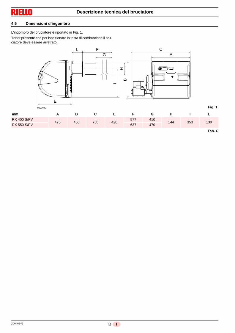
L’ingombro del bruciatore è riportato in Fig. 1.
Tener presente che per ispezionare la testa di combustione il bru-ciatore deve essere arretrato.
Tab. C
H
E
L FG
I
A
B
C
Fig. 120047384
mm A B C E F G H I L
RX 400 S/PV475 456 730 420
577 410144 353 130
RX 550 S/PV 637 470

9 20046745I
Descrizione tecnica del bruciatore
4.6 Descrizione bruciatore
1 Testa di combustione2 Elettrodo d’accensione3 Sonda per il controllo presenza fiamma4 Valvola gas5 Miscelatore aria gas nel circuito di aspirazione 6 Presa di pressione gas7 Condotto gas valvola - Venturi 8 Ingresso gas9 Flangia per il fissaggio alla caldaia10 Ventilatore11 Passaggio aria nel ventilatore12 Apparecchiatura elettrica con avvisatore luminoso del tipo di
blocco13 Pulsante di sblocco14 Spina-presa sul cavo della sonda di ionizzazione 15 Prese per il collegamento elettrico16 Trasformatore 17 Piastrina predisposta per ottenere 4 fori, utili al passaggio
dei cavi elettrici
4.7 Materiale a corredo
Flangia per rampa gas . . . . . . . . . . . . . . . . . . . . . . . . . . . . . N. 1
Viti per fissare la valvola M 5 x 16 . . . . . . . . . . . . . . . . . . . . N. 4
Schermo isolante . . . . . . . . . . . . . . . . . . . . . . . . . . . . . . . . . N. 1
Valvola gas. . . . . . . . . . . . . . . . . . . . . . . . . . . . . . . . . . . . . . N. 1
Spina a 4 poli . . . . . . . . . . . . . . . . . . . . . . . . . . . . . . . . . . . N. 1
Spina a 7 poli . . . . . . . . . . . . . . . . . . . . . . . . . . . . . . . . . . . N. 1
Istruzione . . . . . . . . . . . . . . . . . . . . . . . . . . . . . . . . . . . . . . . N. 1
Catalogo ricambi . . . . . . . . . . . . . . . . . . . . . . . . . . . . . . . . . N. 1
Minuteria per fissaggio bruciatore:
Grani 8 x 50 INOX (con o senza punta) . . . . . . . . . . . . . . . . N. 4
Rondelle zincate 8 x 16 . . . . . . . . . . . . . . . . . . . . . . . . . . . . N. 4
Rondelle dentellate zincate da 8. . . . . . . . . . . . . . . . . . . . . . N. 4
Dadi zincati M8 . . . . . . . . . . . . . . . . . . . . . . . . . . . . . . . . . . . N. 4
4
5
6
7
8
11
13
17
16
15
1 2
3
9 10
11
1214
Fig. 220047367
ATTENZIONE
Vi è una possibilità di blocco del bruciatore.
BLOCCO APPARECCHIATURA: l’accensione del pulsante dell’apparecchiatura13)(Fig. 2) avverte che il bruciatore è in blocco.Per sbloccare premere il pulsante.
20046745 10 I
Installazione
5.1 Note sulla sicurezza per l’installazione
Dopo avere effettuato un’accurata pulizia tutt’intorno all’area de-stinata all’installazione del buciatore ed avere provveduto ad unacorretta illuminazione dell’ambiente, procedere con le operazionidi installazione.
5.2 Movimentazione
L’imballo del bruciatore è comprensivo di pedana in legno, è pos-sibile quindi movimentare il bruciatore, quando è ancora imballa-to, con carrello transpallet o carrello elevatore a forche.
5.3 Controlli preliminari
Controllo della fornitura
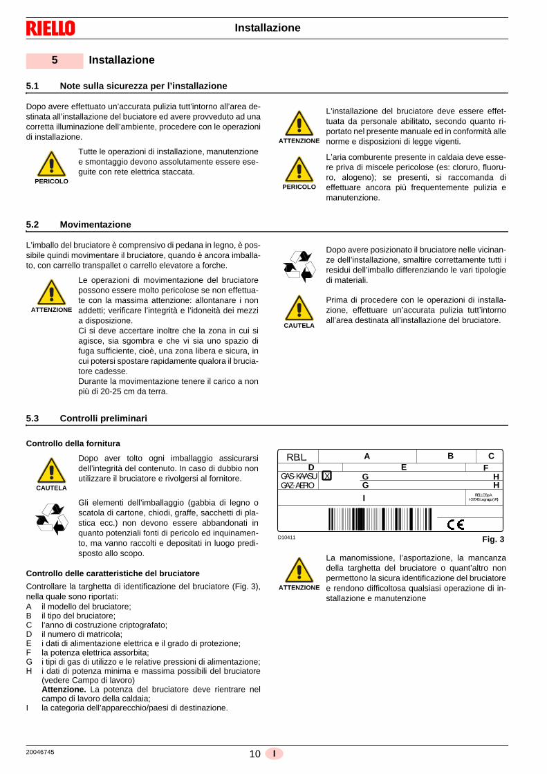
Controllo delle caratteristiche del bruciatore
Controllare la targhetta di identificazione del bruciatore (Fig. 3),nella quale sono riportati:A il modello del bruciatore;B il tipo del bruciatore;C l’anno di costruzione criptografato;D il numero di matricola;E i dati di alimentazione elettrica e il grado di protezione;F la potenza elettrica assorbita;G i tipi di gas di utilizzo e le relative pressioni di alimentazione;H i dati di potenza minima e massima possibili del bruciatore
(vedere Campo di lavoro)Attenzione. La potenza del bruciatore deve rientrare nelcampo di lavoro della caldaia;
I la categoria dell’apparecchio/paesi di destinazione.
5 Installazione
PERICOLO
Tutte le operazioni di installazione, manutenzionee smontaggio devono assolutamente essere ese-guite con rete elettrica staccata.
ATTENZIONE
L’installazione del bruciatore deve essere effet-tuata da personale abilitato, secondo quanto ri-portato nel presente manuale ed in conformità allenorme e disposizioni di legge vigenti.
PERICOLO
L’aria comburente presente in caldaia deve esse-re priva di miscele pericolose (es: cloruro, fluoru-ro, alogeno); se presenti, si raccomanda dieffettuare ancora più frequentemente pulizia emanutenzione.
ATTENZIONE
Le operazioni di movimentazione del bruciatorepossono essere molto pericolose se non effettua-te con la massima attenzione: allontanare i nonaddetti; verificare l’integrità e l’idoneità dei mezzia disposizione.Ci si deve accertare inoltre che la zona in cui siagisce, sia sgombra e che vi sia uno spazio difuga sufficiente, cioè, una zona libera e sicura, incui potersi spostare rapidamente qualora il brucia-tore cadesse.Durante la movimentazione tenere il carico a nonpiù di 20-25 cm da terra.
Dopo avere posizionato il bruciatore nelle vicinan-ze dell’installazione, smaltire correttamente tutti iresidui dell’imballo differenziando le vari tipologiedi materiali.
CAUTELA
Prima di procedere con le operazioni di installa-zione, effettuare un’accurata pulizia tutt’intornoall’area destinata all’installazione del bruciatore.
CAUTELA
Dopo aver tolto ogni imballaggio assicurarsidell’integrità del contenuto. In caso di dubbio nonutilizzare il bruciatore e rivolgersi al fornitore.
Gli elementi dell’imballaggio (gabbia di legno oscatola di cartone, chiodi, graffe, sacchetti di pla-stica ecc.) non devono essere abbandonati inquanto potenziali fonti di pericolo ed inquinamen-to, ma vanno raccolti e depositati in luogo predi-sposto allo scopo.
ATTENZIONE
La manomissione, l’asportazione, la mancanzadella targhetta del bruciatore o quant’altro nonpermettono la sicura identificazione del bruciatoree rendono difficoltosa qualsiasi operazione di in-stallazione e manutenzione
R.B.L.
GAS-KAASUGAZ-AEPIO
X
RIELLO S.p.A.I-37045 Legnago (VR)
AD E
B CF
I
G HG H
Fig. 3D10411
11 20046745I
Installazione
5.4 Posizione di funzionamento
5.5 Predisposizione della caldaia
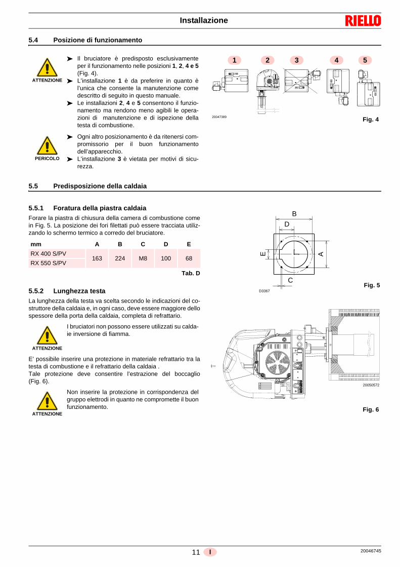
5.5.1 Foratura della piastra caldaia
Forare la piastra di chiusura della camera di combustione comein Fig. 5. La posizione dei fori filettati può essere tracciata utiliz-zando lo schermo termico a corredo del bruciatore.
Tab. D
5.5.2 Lunghezza testa
La lunghezza della testa va scelta secondo le indicazioni del co-struttore della caldaia e, in ogni caso, deve essere maggiore dellospessore della porta della caldaia, completa di refrattario.
E’ possibile inserire una protezione in materiale refrattario tra latesta di combustione e il refrattario della caldaia .Tale protezione deve consentire l’estrazione del boccaglio(Fig. 6).
ATTENZIONE
Il bruciatore è predisposto esclusivamenteper il funzionamento nelle posizioni 1, 2, 4 e 5(Fig. 4).
L’installazione 1 è da preferire in quanto èl’unica che consente la manutenzione comedescritto di seguito in questo manuale.
Le installazioni 2, 4 e 5 consentono il funzio-namento ma rendono meno agibili le opera-zioni di manutenzione e di ispezione dellatesta di combustione.
PERICOLO
Ogni altro posizionamento è da ritenersi com-promissorio per il buon funzionamentodell’apparecchio.
L’installazione 3 è vietata per motivi di sicu-rezza.
Fig. 4
2 3 4 51
20047389
mm A B C D E
RX 400 S/PV163 224 M8 100 68
RX 550 S/PV
ATTENZIONE
I bruciatori non possono essere utilizzati su calda-ie inversione di fiamma.
ATTENZIONE
Non inserire la protezione in corrispondenza delgruppo elettrodi in quanto ne compromette il buonfunzionamento.
E
C
B
D
A
Fig. 5D3367
Fig. 6
20050572

20046745 12 I
Installazione
5.6 Fissaggio del bruciatore alla caldaia
I bruciatori sono forniti con la testa di combustione e gli elettrodigià montati.
Prima di fissare il bruciatore alla caldaia, verificare se la sonda egli elettrodi sono correttamente posizionati come in Fig. 7.
Per fissare il bruciatore alla caldaia, procedere come segue: Fissare il gruppo rampa 20)(Fig. 8) mediante le 4 viti
18)(Fig. 8) presenti a corredo. Attenzione alla presenza della guarnizione 19)(Fig. 8) e alla
tenuta gas. Avvitare i prigionieri 2)(Fig. 9) alla piastra della caldaia
1)(Fig. 9). Posizionare lo schermo refrattario 3)(Fig. 9) e la guarnizione
in gomma siliconica 4)(Fig. 9).
Fissare la flangia 4)(Fig. 9) alla piastra della caldaia ed avvitare idadi 5)(Fig. 9).
Durante questa operazione fare attenzione a non manomettere ilgruppo elettrodi.
Predisporre un adeguato sistema di sollevamen-to.
ATTENZIONE
La tenuta bruciatore-caldaia deve essere er-metica.
6 mm
9 mm
4-5
mm
20047399
Fig. 7
19
18
20
Fig. 8
20050578
12345
D8666 Fig. 9

13 20046745I
Installazione
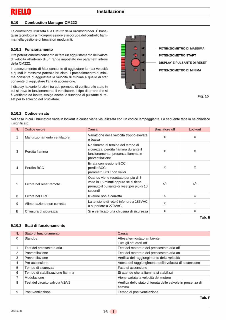
5.7 Alimentazione combustibile
I bruciatori sono abbinati a valvole gas monoblocco di tipo pneu-matico proporzionale, che consentono di modulare la quantità digas erogata e quindi la potenza sviluppata.Un segnale di pressione rilevato al circuito aria è portato alla val-
vola gas pneumatica, la quale eroga una quantità di gas propor-zionale alla portata di aria elaborata dal ventilatore.
Miscelatore aria/gas
La miscelazione del gas con l’aria comburente avviene all’internodel circuito di ventilazione (miscelatore), a partire dall’ingressodella bocca di aspirazione.
Attraverso la rampa gas il combustibile viene inserito nella venad’aria in aspirazione e con l’ausilio di un mixer ha inizio una mi-scelazione ottimale.
NOTA:Il tubo (T) tra valvola-Venturi consente di compensare l’acci-dentale occlusione dell’aspirazione mediante la riduzionedel gas erogato. Dopo aver collegato il tubo di compensazio-ne (T) con la valvola, ricoprirlo con la protezione in gomma.
5.7.1 Rampa gas
E’ omologata assieme al bruciatore secondo norma EN 676 eviene fornita a corredo (Fig. 11).
Legenda (Fig. 11)1 Condotto arrivo del gas2 Valvola manuale3 Giunto antivibrante4 Manometro con rubinetto a pulsante5 Valvola comprendente:
- filtro (sostituibile)- valvola di funzionamento- regolatore di pressione
P1- Pressione a monte del filtroP2- Pressione a valle valvolaL - Rampa gas fornita a corredoL1 - A cura dell’installatore
Rischio di esplosione a causa di fuoriuscita dicombustibile in presenza di fonte infiammabile.
Precauzioni: evitare urti, attriti, scintille, calore.
Verificare la chiusura del rubinetto di intercettazio-ne del combustibile, prima di effettuare qualsiasitipo di intervento sul bruciatore.
ATTENZIONE
L’installazione della linea di alimentazione delcombustibile deve essere effettuata da personaleabilitato, in conformità alle norme e disposizioni dilegge vigenti.
Fig. 10
D7803
Valvola gas
Punto di prova
pressione del gas
a monte (P1)
Tubo di compensazione (T)
Protezione metallica
Pressacavo
Tubo di compensazione (T)
Miscelatore aria/gas(Venturi) nel circuitodi aspirazione
Regolazione flusso gas massimo (V1)
Punto di prova di pressione a valle (P2)
Regolazione flusso gas
minimo sullo stabilizzatore (V2)
+-
+
-
Fig. 11
L1 L
VS VRRF
1 2 3
4 5
P2P1
20046745 14 I
Installazione
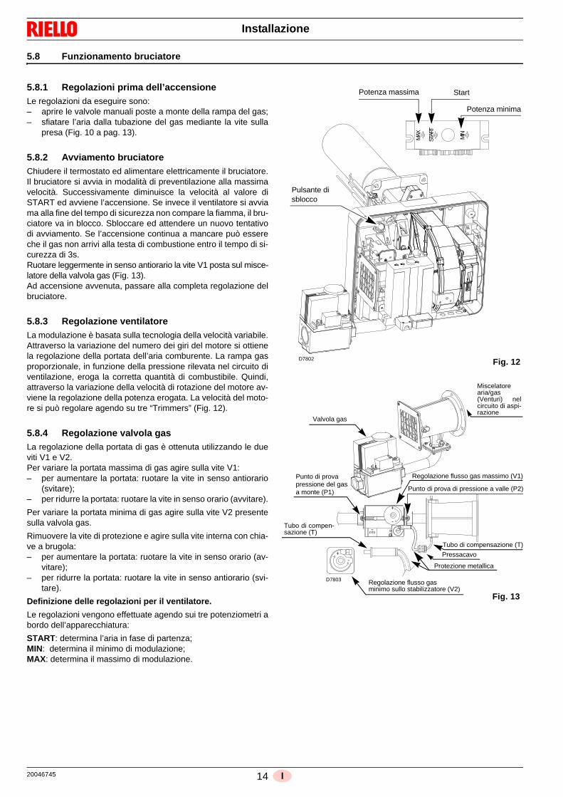
5.8 Funzionamento bruciatore
5.8.1 Regolazioni prima dell’accensione
Le regolazioni da eseguire sono:– aprire le valvole manuali poste a monte della rampa del gas;– sfiatare l’aria dalla tubazione del gas mediante la vite sulla
presa (Fig. 10 a pag. 13).
5.8.2 Avviamento bruciatore
Chiudere il termostato ed alimentare elettricamente il bruciatore.Il bruciatore si avvia in modalità di preventilazione alla massimavelocità. Successivamente diminuisce la velocità al valore diSTART ed avviene l’accensione. Se invece il ventilatore si avviama alla fine del tempo di sicurezza non compare la fiamma, il bru-ciatore va in blocco. Sbloccare ed attendere un nuovo tentativodi avviamento. Se l’accensione continua a mancare può essereche il gas non arrivi alla testa di combustione entro il tempo di si-curezza di 3s.Ruotare leggermente in senso antiorario la vite V1 posta sul misce-latore della valvola gas (Fig. 13).Ad accensione avvenuta, passare alla completa regolazione delbruciatore.
5.8.3 Regolazione ventilatore
La modulazione è basata sulla tecnologia della velocità variabile.Attraverso la variazione del numero dei giri del motore si ottienela regolazione della portata dell’aria comburente. La rampa gasproporzionale, in funzione della pressione rilevata nel circuito diventilazione, eroga la corretta quantità di combustibile. Quindi,attraverso la variazione della velocità di rotazione del motore av-viene la regolazione della potenza erogata. La velocità del moto-re si può regolare agendo su tre “Trimmers” (Fig. 12).
5.8.4 Regolazione valvola gas
La regolazione della portata di gas è ottenuta utilizzando le dueviti V1 e V2.Per variare la portata massima di gas agire sulla vite V1:– per aumentare la portata: ruotare la vite in senso antiorario
(svitare);– per ridurre la portata: ruotare la vite in senso orario (avvitare).
Per variare la portata minima di gas agire sulla vite V2 presentesulla valvola gas.
Rimuovere la vite di protezione e agire sulla vite interna con chia-ve a brugola:– per aumentare la portata: ruotare la vite in senso orario (av-
vitare);– per ridurre la portata: ruotare la vite in senso antiorario (svi-
tare).
Definizione delle regolazioni per il ventilatore.
Le regolazioni vengono effettuate agendo sui tre potenziometri abordo dell’apparecchiatura:
START: determina l’aria in fase di partenza;MIN: determina il minimo di modulazione;MAX: determina il massimo di modulazione.
Fig. 12
MAX
STAR
T
MIN
Pulsante di sblocco
Potenza massima Start
Potenza minima
D7802
Fig. 13
Regolazione flusso gas minimo sullo stabilizzatore (V2)
Valvola gas
Punto di provapressione del gasa monte (P1)
Protezione metallica
Pressacavo
Tubo di compensazione (T)
Regolazione flusso gas massimo (V1)
Punto di prova di pressione a valle (P2)
+-
+
-
D7803
Tubo di compen-sazione (T)
Miscelatorearia/gas (Venturi) nelcircuito di aspi-razione

15 20046745I
Installazione
5.9 Collegamenti elettrici
Note sulla sicurezza per i collegamenti elettrici
Prima di effettuare qualsiasi operazione di manutenzione, puliziao controllo:
Se ancora presente, rimuovere il cofano e procedere ai collega-menti elettrici secondo gli schemi elettrici.
Usare cavi flessibili secondo norma EN 60 335-1.
Tutti i cavi da collegare al bruciatore vanno fatti passare dai pas-sacavi.L’utilizzo dei passacavi può avvenire in vari modi; a scopo esem-plificativo indichiamo il modo seguente:
RX 400 S/PV1- Presa 7 poli per alimentazione monofase, termo-
stato/pressostato TL2- Presa 4 poli per termostato/pressostato TR3- Presa 2 poli per accessorio sblocco apparecchiatura
a distanza 4 - 4A Predisposizioni per bocchettoni
(Forare in caso di necessità dei bocchettoni 6A)5 - Spine 2 poli per comando 0-10 Volt.
RX 550 S/PV1- Presa 7 poli per alimentazione monofase, termo-
stato/pressostato TL2- Presa 4 poli per termostato/pressostato TR3- Presa 2 poli per accessorio sblocco apparecchiatura
a distanza 4 - 4A Predisposizioni per bocchettoni
(Forare in caso di necessità dei bocchettoni 6A)5 - Spine 2 poli per comando 0-10 Volt.
PERICOLO
I collegamenti elettrici devono essere eseguiti in assenza di alimentazione elettrica. I collegamenti elettrici devono essere eseguiti secondo le norme vigenti del paese di destinazione e da personale
qualificato. Fare riferimento agli schemi elettrici. Il costruttore declina ogni responsabilità da modifiche o collegamenti diversi da quelli rappresentati negli schemi
elettrici. Verificare che l’alimentazione elettrica del bruciatore corrisponda a quella riportata nella targhetta di identifica-
zione e nel presente manuale. Il bruciatore è stato omologato per funzionamento intermittente.
Ciò significa che devono fermarsi "per Norma" almeno 1 volta ogni 24 ore per permettere all'apparecchiatura dieffettuare un controllo della propria efficienza all’avviamento. Normalmente l’arresto del bruciatore viene assicu-rato dal termostato/pressostato della caldaia.
Se così non fosse è necessario applicare in serie a TL un interruttore orario che provveda all'arresto del brucia-tore almeno 1 volta ogni 24 ore. Fare riferimento agli schemi elettrici.
La sicurezza elettrica dell’apparecchio è raggiunta soltanto quando lo stesso è correttamente collegato ad un effi-cace impianto di messa a terra, eseguito come previsto dalle norme vigenti. È necessario verificare questo fonda-mentale requisito di sicurezza. In caso di dubbio, far effettuare da personale abilitato un accurato controllodell’impianto elettrico. Non utilizzare i tubi del gas come messa a terra di apparecchi elettrici.
L’impianto elettrico deve essere adeguato alla potenza massima assorbita dall’apparecchio, indicata in targa enel manuale, accertando in particolare che la sezione dei cavi sia idonea alla potenza assorbita dall’apparecchio.
Per l’alimentazione generale dell’apparecchio dalla rete elettrica:- non usare adattatori, prese multiple, prolunghe;- prevedere un interruttore omnipolare con apertura tra i contatti di almeno 3 mm (categoria sovratensione III),
come previsto dalle normative di sicurezza vigenti. Non toccare l’apparecchio con parti del corpo bagnate o umide e/o a piedi nudi. Non tirare i cavi elettrici.
PERICOLO
Togliere l’alimentazione elettrica al bruciatore,agendo sull’interruttore generale dell’impianto.
PERICOLO
Chiudere il rubinetto di intercettazione del combu-stibile.
PERICOLO
Evitare la formazione di condensa, ghiaccio e in-filtrazioni d’acqua.
Effettuate tutte le operazioni di manutenzione, pu-lizia o controllo, rimontare il cofano e tutti i dispo-sitivi di sicurezza e protezione del bruciatore.
2
14
53
Fig. 14
D10842
20046745 16 I
Installazione
5.10 Combustion Manager CM222
La control box utilizzata è la CM222 della Kromschroder. È basa-ta su tecnologia a microprocessore e si occupa del controllo fiam-ma nella gestione di bruciatori modulanti.
5.10.1 Funzionamento
I tre potenziomentri consento di fare un aggiustamento del valoredi velocità all’interno di un range impostato nei parametri internidella CM222.
Il potenziomentro di Max consente di aggiustare la max velocitàe quindi la massima potenza bruciata, il potenziomentro di mini-ma consente di aggiustare la velocità di minima e quello di starconsente di aggiustare l’aria di accensione.
Il display ha varie funzioni tra cui: permette di verificare lo stato incui si trova in funzionamento il ventilatore, il tipo di errore che siè verificato ed inoltre svolge anche la funzione di pulsante di re-set per lo sblocco del bruciatore.
5.10.2 Codice errato
Nel caso in cui il bruciatore vada in lockout la causa viene visualizzata con un codice lampeggiante. La seguente tabella ne chiarisceil significato:
Tab. E
5.10.3 Stati di funzionamento
Tab. F
Fig. 15
POTENZIOMETRO DI MASSIMA
POTENZIOMETRO START
DISPLAY E PULSANTE DI RESET
POTENZIOMETRO DI MINIMA
N. Codice errore Causa Bruciatore off Lockout
1 Malfunzionamento ventilatoreVariazione della velocità troppo elevata o bassa
x x
3 Perdita fiamma
No fiamma al temine del tempo di sicurezza; perdita fiamma durante il funzionamento; presenza fiamma in preventilazione
x x
4 Perdita BCCErrata connessione BCC; perditaBCC; parametri BCC non validi
x x
5 Errore nel reset remoto
Quando viene resettato per più di 5 volte in 15 minuti oppure se si tiene premuto il pulsante di reset per più di 10 secondi
x/- x/-
8 Errore nel CRC Il valore non è corretto x x
9 Alimentazione non correttaLa tensione di rete è inferiore a 185VAC o superiore a 270VAC
x -
E Chiusura di sicurezza Si è verificato una chiusura di sicurezza x x
N. Stato di funzionamento Causa0 Standby Attesa termostato ambiente;
Tutti gli attuatori off
1 Test del pressostato aria Test del motore e del pressostato aria off
2 Preventilazione Test del motore e del pressostato aria on3 Preventilazione Verifica del raggiungimento della velocità
4 Pre-accensione Attesa del raggiungimento della velocità di accensione
5 Tempo di sicurezza Fase di accensione6 Tempo di stabilizzazione fiamma Si attende che la fiamma si stabilizzi
7 Modulazione Viene variata la velocità del motore
8 Test del circuito valvola V1/V2 Verifica dello stato di tenuta delle valvole in presenza di fiamma
9 Post-ventilazione Tempo di post ventilazione
17 20046745I
Installazione
5.10.4 Parametri di sicurezza
Tab. G
BCC (CHIP CARD)
La BCC è una scheda in cui si possono facilmente caricare i pa-rametri di funzionamento del bruciatore tramite PC.
N. Parametro Min. Max. OEM-preset Valore
1 Tempo di preventilazione 0,2 51 51 Secondi
2 Tempo di sicurezza 0,1 10 3 Secondi3 Tempo stabilizzazione fiamma 0,1 25,5 10 Secondi
4 Tentativi di accensione 1 5 3 Numero
5 Tempo di post ventilazione 0,2 51 0 Secondi6 Tempo di preaccensione 0,1 25,5 3 Secondi
7 Tempo di accensione 0,1 25,5 3 Secondi
8 Velocità di post ventilazione 780 9960 1980 Giri/min9 Velocità massima 780 9960 6000 Giri/min
10 Tempo di test V1 0,1 25,5 1 Secondi
11 Pulsetime V1 0,1 25,5 2 Secondi
12 Tempo di test V2 0,1 25,5 2,5 Secondi13 Pulsetime V2 0,1 25,5 2 Secondi
14 Limite minimo velocita massima 780 9960 4020 Giri/min
15 Limite massimo velocità minima 780 9960 2280 Giri/min16 Impulsi a giro 1 4 3 Impulsi/giro
17 Frequenza del controllo della
velocità
1 2 2 Hz
18 No airpress switch 0 1 - -
19 Test permanente APS 0 1 - -
20 No feedback dal motore 0 1 4 -21 No pressostato gas 0 1 - -
22 Ripartenza 0 1 - -
23 Controllo valvola gas 0 1 4 -24 Test di tenuta valvola 0 1 - -

20046745 18 I
Messa in funzione, taratura e funzionamento del bruciatore
6.1 Note sulla sicurezza per la prima messa in funzione
6.2 Regolazione bruciatore
Per ottenere una regolazione ottimale del bruciatore è necessa-rio effettuare l’analisi dei gas di scarico della combustioneall’uscita del generatore. In conformità con la Direttiva Rendi-mento 92/42/CEE, l’applicazione del bruciatore al generatore, laregolazione e il collaudo, devono essere eseguiti nell’osservanzadel manuale d’istruzione del generatore stesso, compreso il con-trollo della concentrazione di CO e CO2 nei fumi e della loro tem-peratura.
Verificare in successione:
- potenza MAX;
- potenza MIN;
- potenza di accensione.
La potenza massima dovrà corrispondere a quella richiesta dallacaldaia utilizzata. Per aumentare o diminuire il suo valore agiresul trimmer MAX posto sull’apparecchiatura (Fig. 12 a pag. 14).Misurare la portata di gas al contatore per individuare esattamen-te la potenza bruciata.
Mediante un analizzatore dei fumi misurare il valore della CO2 odel O2 al fine di ottimizzare la taratura del bruciatore. I valori corretti sono: CO2 8,2 ÷ 9%.
Per correggere tali valori agire sulla valvola gas nel seguente mo-do:– per aumentare la portata gas e la CO2: ruotare la vite V1 in
senso antiorario (svitare);– per ridurre la portata del gas e la CO2: ruotare la vite V1 in
senso orario (avvitare).
La potenza minima dovrà corrispondere a quella richiesta dallacaldaia utilizzata. Per aumentare o diminuire il suo valore agiresul trimmer MIN posto sull’apparecchiatura (Fig. 12 a pag. 14).
Misurare la portata di gas al contatore per individuare esattamen-te la potenza bruciata.
Mediante un analizzatore dei fumi misurare il valore della CO2 odel O2 al fine di ottimizzare la taratura del bruciatore.
I valori corretti sono: CO2 7,8 ÷ 8,5%.
Per correggere tali valori agire sulla valvola gas nel seguente mo-do:– per aumentare la portata gas e la CO2: ruotare la vite V2 in
senso orario (avvitare);– per ridurre la portata del gas e la CO2: ruotare la vite V2 in
senso antiorario (svitare).
6.2.1 Valori ottimali di taratura
Tab. H
6 Messa in funzione, taratura e funzionamento del bruciatore
ATTENZIONE
La prima messa in funzione del bruciatore deveessere effettuata da personale abilitato, secondoquanto riportato nel presente manuale ed in con-formità alle norme e disposizioni di legge vigenti. ATTENZIONE
Verificare la corretta funzionalità dei dispositivi diregolazione, comando e sicurezza.
Potenza MIN Potenza MAX
CO2 (%) O2 (%) CO2 (%) O2 (%)
METANO 8 6,6 8,5 5,7
GPL 9,5 6,4 10 5,6
Fig. 16D9714
19 20046745I
Messa in funzione, taratura e funzionamento del bruciatore
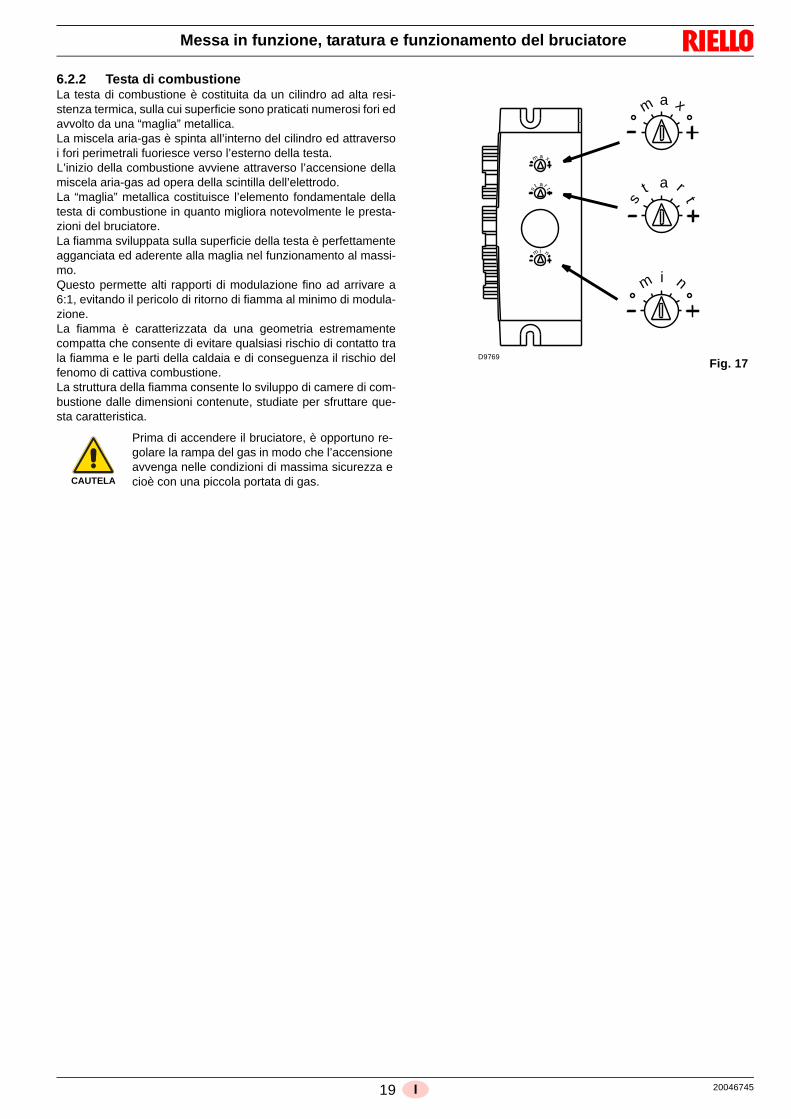
6.2.2 Testa di combustioneLa testa di combustione è costituita da un cilindro ad alta resi-stenza termica, sulla cui superficie sono praticati numerosi fori edavvolto da una “maglia” metallica. La miscela aria-gas è spinta all’interno del cilindro ed attraversoi fori perimetrali fuoriesce verso l’esterno della testa. L’inizio della combustione avviene attraverso l’accensione dellamiscela aria-gas ad opera della scintilla dell’elettrodo. La “maglia” metallica costituisce l’elemento fondamentale dellatesta di combustione in quanto migliora notevolmente le presta-zioni del bruciatore. La fiamma sviluppata sulla superficie della testa è perfettamenteagganciata ed aderente alla maglia nel funzionamento al massi-mo. Questo permette alti rapporti di modulazione fino ad arrivare a6:1, evitando il pericolo di ritorno di fiamma al minimo di modula-zione. La fiamma è caratterizzata da una geometria estremamentecompatta che consente di evitare qualsiasi rischio di contatto trala fiamma e le parti della caldaia e di conseguenza il rischio delfenomo di cattiva combustione. La struttura della fiamma consente lo sviluppo di camere di com-bustione dalle dimensioni contenute, studiate per sfruttare que-sta caratteristica.
CAUTELA
Prima di accendere il bruciatore, è opportuno re-golare la rampa del gas in modo che l’accensioneavvenga nelle condizioni di massima sicurezza ecioè con una piccola portata di gas.
m a x
m i n
t a r
s t
m a
t a r
s
m i n
tx
Fig. 17D9769

20046745 20 I
Manutenzione
7.1 Note sulla sicurezza per la manutenzione
La manutenzione periodica è essenziale per il buon funziona-mento, la sicurezza, il rendimento e la durata del bruciatore.
Essa consente di ridurre i consumi, le emissioni inquinanti e dimantenere il prodotto affidabile nel tempo.
Prima di effettuare qualsiasi operazione di manutenzione, puliziao controllo:
7.2 Programma di manutenzione
7.2.1 Frequenza della manutenzione
7.2.2 Controllo e pulizia
CombustioneEffettuare l’analisi dei gas di scarico della combustione. Gli scostamenti significativi rispetto al precedente controllo indi-cheranno i punti dove più attenta dovrà essere l’operazione dimanutenzione.
Testa di combustioneAprire il bruciatore e verificare che tutte le parti della testa dicombustione siano integre, non deformate dall’alta temperatu-ra, prive di impurità provenienti dall’ambiente e correttamenteposizionate.
BruciatoreControllare che non vi siano usure anomale o viti allentate. Pulire esternamente il bruciatore.Pulire e ingrassare il profilo variabile delle camme.
VentilatoreVerificare che all’interno del ventilatore e sulle pale della girantenon vi sia accumulo di polvere: riduce la portata d’aria e causa,conseguentemente, combustione inquinante.
Corrente di ionizzazione (Fig. 18)
La corrente minima per far funzionare l’apparecchiatura è 5 µA.
Il bruciatore dà una corrente nettamente superiore, tale da non ri-chiedere normalmente alcun controllo.
Qualora, comunque, si voglia misurare la corrente di ionizzazio-ne bisogna aprire il connettore (CN1) inserito nel filo rosso ed in-serire un microamperometro.
CaldaiaPulire la caldaia secondo le istruzioni che l’accompagnano inmodo da poter riavere i dati di combustione originari, specialmen-te: pressione in camera di combustione e temperature fumi.
Fughe di gasControllare che non vi siano fughe di gas sul condotto contatore-bruciatore.
Filtro del gasSostituire il filtro del gas quando è sporco.
7 Manutenzione
PERICOLO
Gli interventi di manutenzione e la taratura delbruciatore devono essere effettuati esclusivamen-te da personale abilitato ed autorizzato, secondoquanto riportato nel presente manuale ed in con-formità alle norme e disposizioni di legge vigenti.
PERICOLO
Togliere l’alimentazione elettrica al bruciatore,agendo sull’interruttore generale dell’impianto.
PERICOLO
Chiudere il rubinetto di intercettazione del combu-stibile.
Attendere il completo raffreddamento dei compo-nenti a contatto con fonti di calore.
L’impianto di combustione a gas va fatto control-lare almeno una volta all’anno da un incaricatodella Ditta Costruttrice o da altro tecnico specializ-zato.
L’operatore deve utilizzare l’attrezzatura necessa-ria nello svolgimento dell’attività di manutenzione.
Fig. 18D5006
Sonda
Connettore
Apparecchiatura

21 20046745I
Manutenzione
CombustioneQualora i valori della combustione trovati all’inizio dell’interventonon soddisfino le Norme vigenti o, comunque, non corrispondanoad una buona combustione, consultare la tabella sottostante edeventualmente contattare l’Assistenza Tecnica per effettuare ledovute regolazioni.
Tab. I
7.3 Apertura e chiusura bruciatore
EN 676Eccesso d’aria
COPotenza max. 1,2
Potenza max. 1,3
GASCO2 max. teorico
0 % O2
Taratura CO2 %mg/kWh
= 1,2 = 1,3
G 20 11,7 9,7 9 1000
G 25 11,5 9,5 8,8 1000
G 30 14,0 11,6 10,7 1000
G 31 13,7 11,4 10,5 1000
PERICOLO
Togliere l’alimentazione elettrica al bruciatore,agendo sull’interruttore generale dell’impianto.
PERICOLO
Chiudere il rubinetto di intercettazione del combu-stibile.
Attendere il completo raffreddamento dei compo-nenti a contatto con fonti di calore.
Effettuate tutte le operazioni di manutenzione, pu-lizia o controllo, rimontare il cofano e tutti i dispo-sitivi di sicurezza e protezione del bruciatore.

20046745 22 I
Appendice - Accessori
Kit regolatore di potenza per funzionamento modulante
Kit diagnostica software
E’ disponibile un kit speciale che identifica la vita del bruciatore mediante collegamento ottico a PC indicandone ore di funzionamento,numero e tipologie di blocchi, numero di giri del motore e i parametri di sicurezza.
Per visualizzare la diagnostica procedere come segue: collegare all’apposita presa dell’apparecchiatura il kit fornito separatamente. La lettura delle informazioni avviene dopo l’avvia-
mento del programma software compreso nel kit.
8 Appendice - Accessori
Kit regolatore di potenza RWF40 Con il funzionamento modulante il bruciatore adegua continuamente la potenza alla richiesta di calore assicurando grande stabilitàal parametro controllato: temperatura o pressione.I componenti da ordinare sono due: • il regolatore di potenza da installare sul bruciatore;• la sonda da installare sul generatore di calore.
Parametro da controllare Sonda Regolatore di potenza
Campo di regolazione Tipo Codice Tipo CodiceTemperatura - 100...+ 500°C PT 100 3010110
RWF40 3010212Pressione 0...2,5 bar
0...16 barSonda con uscita
4...20 mA30102133010214
Bruciatore Codice
RX 400 S/PVRX 550 S/PV
20044365
ATTENZIONE
L’installatore è responsabile per l’eventuale ag-giunta di organi di sicurezza non previsti in questomanuale.

23 20046745I
Appendice - Schema quadro elettrico
AVVIAMENTO E SPEGNIMENTO
9 Appendice - Schema quadro elettrico
APS-Supervision: No APS GPS-Supervision: ActiveValve-Supervision: Tightness control Behaviour after flame loss: Restart
Heat demand
Flame signal
Air pressure switch
Gas pressure switch
Ignition device
Gas valve V1
Gas valve V2
Fan
Operation
Fault signal
Fan speed
1 2 4 5 6 7
Sta
ndst
ill c
heck
Pre
purg
e ch
eck
Pul
setim
e V
1
Che
cktim
e V
2
Pre
purg
e
Wai
ting
for
igni
tion
spee
d
igni
tion
Fla
me
stab
iliza
tion
Pul
setim
e V
2
Che
cktim
e V
1
Pos
tpur
ge
APS-Supervision: No APS GPS-Supervision: ActiveValve-Supervision: Gas valve circuit check Behaviour after flame loss: Restart
Heat demand
Flame signal
Air pressure switch
Gas pressure switch
Ignition device
Gas valve V1
Gas valve V2
Fan
Operation
Fault signal
Fan speed
1 2 3 4 5 6 8
Sta
ndst
ill c
heck
Pre
purg
e ch
eck
Pre
purg
e
Wai
ting
for
igni
tion
spee
d
igni
tion
Fla
me
stab
iliza
tion
Gas
val
ve c
ircui
t ch
eck
On Off Must disappear Must appear Don´t care Alternately on
Inpu
tsO
utpu
ts
Standby
9
Inpu
tsO
utpu
ts
Postpurge
Program step / MessageStandby
0
Normal operation: Start-up and shut down
3
Burner operation
Normal operation: Start-up and shut down
0
Stop StopIgnition *Prepurge Min. - Max.
Stop Prepurge Ignition *
7 9 0
Min. - Max.
Program step / MessageStandby Burner operation
Pos
tpur
ge Standby
Postpurge Stop
0
Termostato
Segnale fiamma
Pressostato aria
Pressostato gas
Trasformatore
Valvola gas V1
Valvola gas V2
Motore
Funzionamento
Segnalazione blocco
Velocità ventilatore(Giri/min.)Stato di funzionamento
Descrizione
Stop Preventilazione Accensione Min. - Max. Post-ventilazione Stop
Tes
t di t
enut
a
Pre
vent
ilazi
one
Tem
po d
i
Atte
sa v
eloc
itàdi
acc
ensi
one
Acc
ensi
one
Sta
biliz
zazi
one
fiam
ma
Funzionamento bruciatore
Tem
po d
i
Tem
po d
i
Tem
po d
i
Pos
t-ve
ntila
zion
e
Standby Standby
Termostato
Segnale fiamma
Pressostato aria
Pressostato gas
Trasformatore
Valvola gas V1
Valvola gas V2
Motore
Funzionamento
Segnalazione blocco
Velocità ventilatore(Giri/min.)
Stato di funzionamento
Descrizione
Stop Preven. Accensione Min. - Max. Post-ventil. Stop
Tes
t di t
enut
a
Pre
vent
ilazi
one
(test
pre
ssos
tato
)
Pre
vent
ilazi
one
Atte
sa v
eloc
itàdi
acc
ensi
one
Acc
ensi
one
Sta
biliz
zazi
one
fiam
ma
Funzionamento bruciatore Standby Standby
Tes
t val
vole
Pos
t-ve
ntila
zion
e
On Off Deve scomparire Deve apparire Ininfluente Variabile tra on e off
valv
ola
(test
pre
ssos
tato
)P
reve
ntila
zion
e
lam
pegg
i V1
cont
rollo
V2
lam
pegg
i V2
cont
rollo
V1
valv
ola
gas
Fig. 19
20046745 24 I
Appendice - Schema quadro elettrico
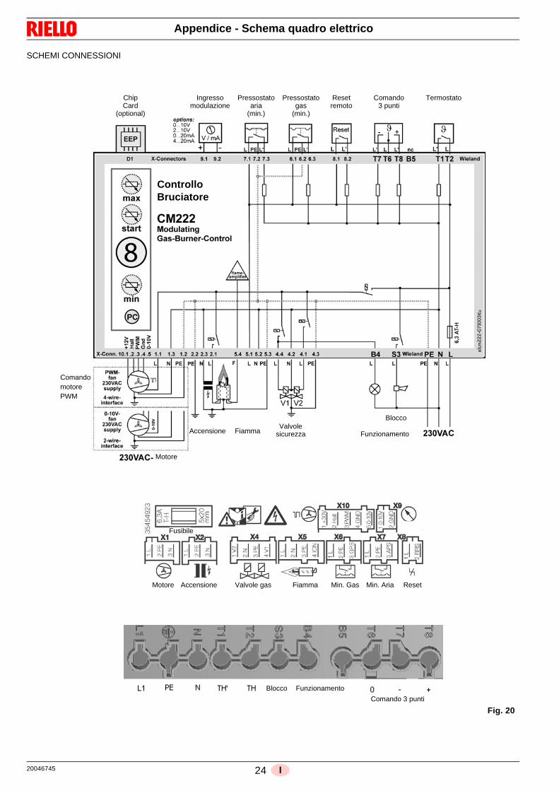
SCHEMI CONNESSIONI
Motore Accensione Valvole gas Fiamma Min. Gas Min. Aria Reset
Blocco
Chip IngressoCard
(optional)modulazione
Pressostatoaria
Pressostatogas
Resetremoto
(min.) (min.)
Comando3 punti
Termostato
ControlloBruciatore
Accensione FiammaValvole
sicurezza Funzionamento
Blocco
Fusibile
Funzionamento
Comando 3 punti
Motore
ComandomotorePWM
Fig. 20

25 20046745I
Appendice - Schema quadro elettrico
Indice schemi
2 Indicazione riferimenti
3 Schema funzionale
4 Schema funzionale
5 Collegamenti elettrici a cura dell’installatore
6 Schema funzionale RWF40
1
2
N. foglio
/1.A1
Coordinate
Indicazione riferimenti


1 20046745GB
Contents
1 Declarations................................................................................................................................................................................ 3
2 Information and general warnings............................................................................................................................................ 4
2.1 Information about the instruction manual .................................................................................................................... 42.1.1 Introduction.................................................................................................................................................................. 42.1.2 General dangers.......................................................................................................................................................... 42.1.3 Other symbols ............................................................................................................................................................. 42.1.4 Delivery of the system and the instruction manual...................................................................................................... 5
2.2 Guarantee and responsibility....................................................................................................................................... 5
3 Safety and prevention................................................................................................................................................................ 6
3.1 Introduction.................................................................................................................................................................. 6
3.2 Personnel training ....................................................................................................................................................... 6
4 Technical description of the burner ......................................................................................................................................... 7
4.1 Models available.......................................................................................................................................................... 7
4.2 Burner categories - Countries of destination ............................................................................................................... 7
4.3 Technical data ............................................................................................................................................................. 7
4.4 Burner weight .............................................................................................................................................................. 7
4.5 Maximum dimensions.................................................................................................................................................. 8
4.6 Burner description ....................................................................................................................................................... 9
4.7 Burner equipment........................................................................................................................................................ 9
5 Installation ................................................................................................................................................................................ 10
5.1 Notes on safety for the installation ............................................................................................................................ 10
5.2 Handling .................................................................................................................................................................... 10
5.3 Preliminary checks .................................................................................................................................................... 10
5.4 Operating position ..................................................................................................................................................... 11
5.5 Preparing the boiler ................................................................................................................................................... 115.5.1 Boring the boiler plate ............................................................................................................................................... 115.5.2 Head length ............................................................................................................................................................... 11
5.6 Securing the burner to the boiler ............................................................................................................................... 12
5.7 Fuel supply ................................................................................................................................................................ 135.7.1 Gas train.................................................................................................................................................................... 13
5.8 Burner operation........................................................................................................................................................ 145.8.1 Adjustments prior to ignition ...................................................................................................................................... 145.8.2 Burner start-up .......................................................................................................................................................... 145.8.3 Fan adjustment.......................................................................................................................................................... 145.8.4 Gas valve adjustment................................................................................................................................................ 14
5.9 Electrical wiring ......................................................................................................................................................... 15
5.10 Combustion Manager CM222 ................................................................................................................................... 165.10.1 Operation................................................................................................................................................................... 165.10.2 Wrong code ............................................................................................................................................................... 165.10.3 Operating statuses .................................................................................................................................................... 165.10.4 Safety Parameters..................................................................................................................................................... 17
6 Start-up, calibration and operation of the burner ................................................................................................................. 18
6.1 Notes on safety for the first start-up .......................................................................................................................... 18
6.2 Burner adjustment ..................................................................................................................................................... 186.2.1 Optimum calibration values ....................................................................................................................................... 186.2.2 Combustion head ...................................................................................................................................................... 19
7 Maintenance.............................................................................................................................................................................. 20
7.1 Notes on safety for the maintenance......................................................................................................................... 20
7.2 Maintenance programme .......................................................................................................................................... 207.2.1 Maintenance frequency ............................................................................................................................................. 207.2.2 Checking and cleaning .............................................................................................................................................. 20
7.3 Opening and closing the burner ................................................................................................................................ 21

20046745 2 GB
Contents
8 Appendix - Accessories ...........................................................................................................................................................22
9 Appendix - Electrical panel layout...........................................................................................................................................23
3 20046745GB
Declarations
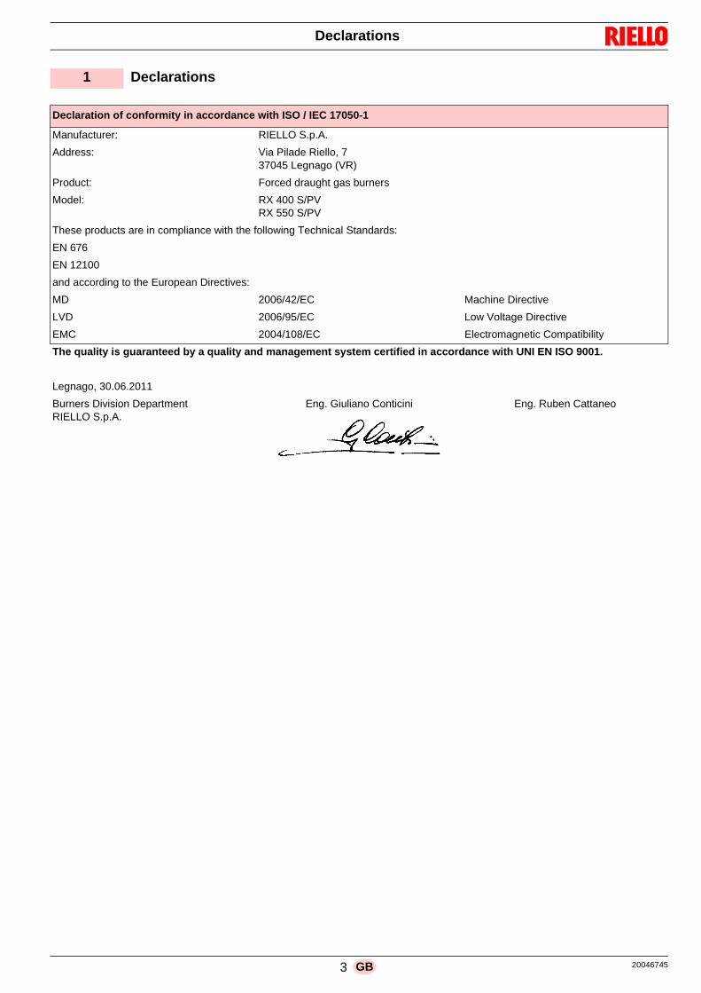
1 Declarations
Declaration of conformity in accordance with ISO / IEC 17050-1
Manufacturer: RIELLO S.p.A.
Address: Via Pilade Riello, 737045 Legnago (VR)
Product: Forced draught gas burners
Model: RX 400 S/PVRX 550 S/PV
These products are in compliance with the following Technical Standards:
EN 676
EN 12100
and according to the European Directives:
MD 2006/42/EC Machine Directive
LVD 2006/95/EC Low Voltage Directive
EMC 2004/108/EC Electromagnetic Compatibility
The quality is guaranteed by a quality and management system certified in accordance with UNI EN ISO 9001.
Legnago, 30.06.2011
Burners Division DepartmentRIELLO S.p.A.
Eng. Giuliano Conticini Eng. Ruben Cattaneo
20046745 4 GB
Information and general warnings
2.1 Information about the instruction manual
2.1.1 Introduction
The instruction manual supplied with the burner: is an integral and essential part of the product and must not
be separated from it; it must therefore be kept carefully forany necessary consultation and must accompany the burnereven if it is transferred to another owner or user, or toanother system. If the manual is lost or damaged, anothercopy must be requested from the Technical AssistanceService of the area;
is designed for use by qualified personnel; offers important indications and instructions relating to the
installation safety, start-up, use and maintenance of theburner.
Symbols used in the manual
In some parts of the manual you will see triangular DANGERsigns. Pay great attention to these, as they indicate a situation ofpotential danger.
2.1.2 General dangers
The dangers can be of 3 levels, as indicated below.
2.1.3 Other symbols
Abbreviations used
Ch. ChapterFig. FigurePage PageSec. SectionTab. Table
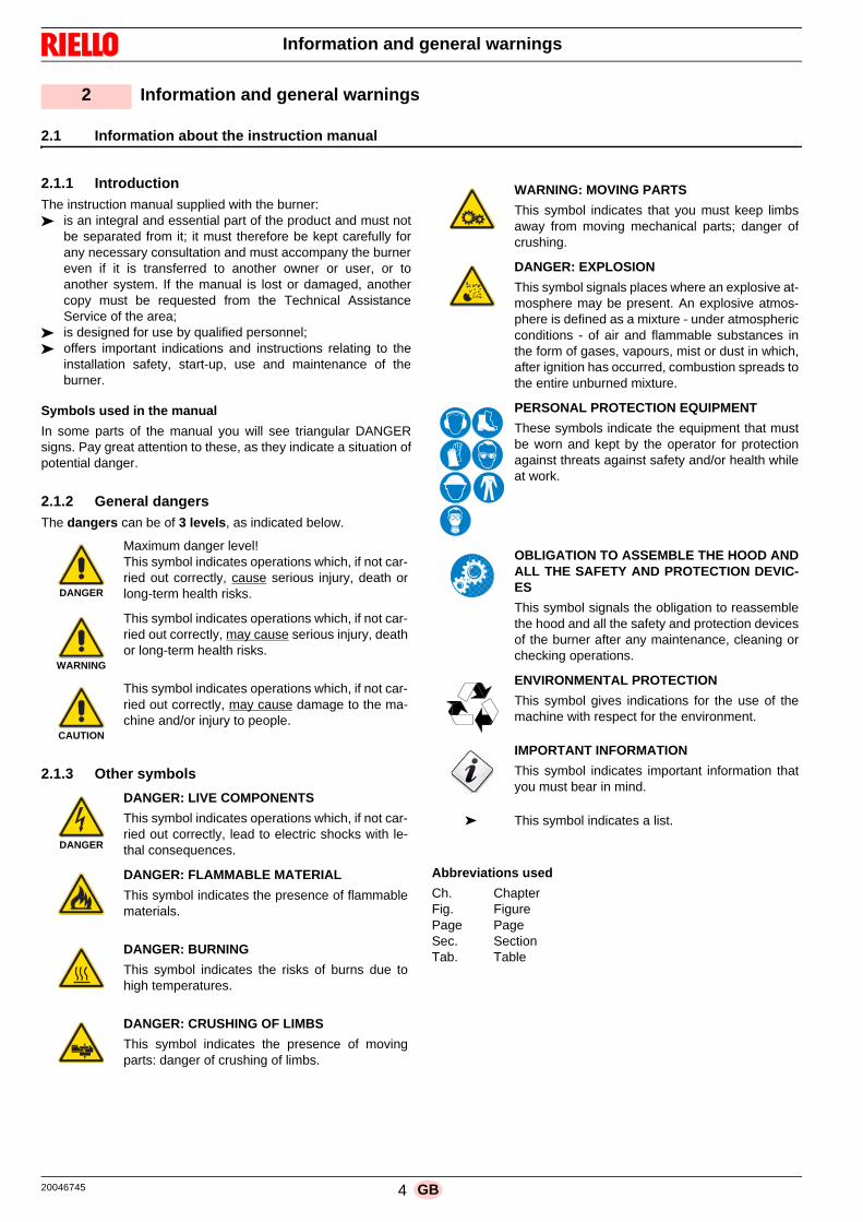
2 Information and general warnings
DANGER
Maximum danger level!This symbol indicates operations which, if not car-ried out correctly, cause serious injury, death orlong-term health risks.
WARNING
This symbol indicates operations which, if not car-ried out correctly, may cause serious injury, deathor long-term health risks.
CAUTION
This symbol indicates operations which, if not car-ried out correctly, may cause damage to the ma-chine and/or injury to people.
DANGER
DANGER: LIVE COMPONENTS
This symbol indicates operations which, if not car-ried out correctly, lead to electric shocks with le-thal consequences.
DANGER: FLAMMABLE MATERIAL
This symbol indicates the presence of flammablematerials.
DANGER: BURNING
This symbol indicates the risks of burns due tohigh temperatures.
DANGER: CRUSHING OF LIMBS
This symbol indicates the presence of movingparts: danger of crushing of limbs.
WARNING: MOVING PARTS
This symbol indicates that you must keep limbsaway from moving mechanical parts; danger ofcrushing.
DANGER: EXPLOSION
This symbol signals places where an explosive at-mosphere may be present. An explosive atmos-phere is defined as a mixture - under atmosphericconditions - of air and flammable substances inthe form of gases, vapours, mist or dust in which,after ignition has occurred, combustion spreads tothe entire unburned mixture.
PERSONAL PROTECTION EQUIPMENT
These symbols indicate the equipment that mustbe worn and kept by the operator for protectionagainst threats against safety and/or health whileat work.
OBLIGATION TO ASSEMBLE THE HOOD ANDALL THE SAFETY AND PROTECTION DEVIC-ES
This symbol signals the obligation to reassemblethe hood and all the safety and protection devicesof the burner after any maintenance, cleaning orchecking operations.
ENVIRONMENTAL PROTECTION
This symbol gives indications for the use of themachine with respect for the environment.
IMPORTANT INFORMATION
This symbol indicates important information thatyou must bear in mind.
This symbol indicates a list.
5 20046745GB
Information and general warnings
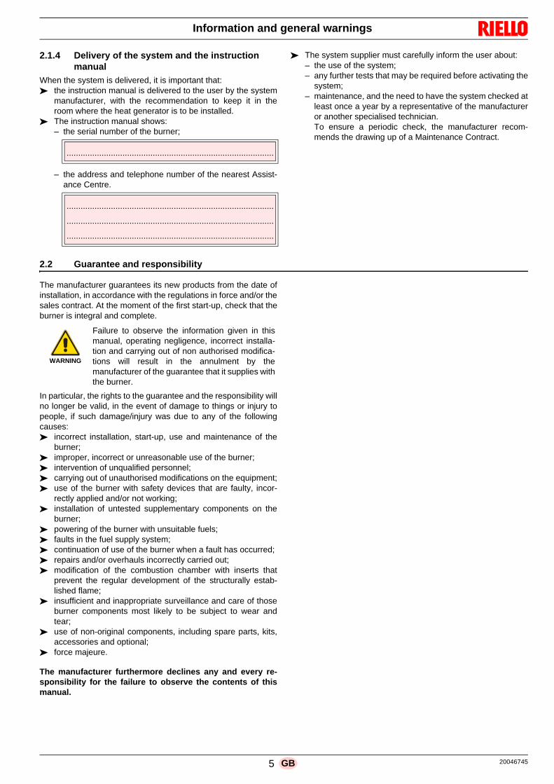
2.1.4 Delivery of the system and the instruction manual
When the system is delivered, it is important that: the instruction manual is delivered to the user by the system
manufacturer, with the recommendation to keep it in theroom where the heat generator is to be installed.
The instruction manual shows:– the serial number of the burner;
– the address and telephone number of the nearest Assist-ance Centre.
The system supplier must carefully inform the user about:– the use of the system; – any further tests that may be required before activating the
system; – maintenance, and the need to have the system checked at
least once a year by a representative of the manufactureror another specialised technician.To ensure a periodic check, the manufacturer recom-mends the drawing up of a Maintenance Contract.
2.2 Guarantee and responsibility
The manufacturer guarantees its new products from the date ofinstallation, in accordance with the regulations in force and/or thesales contract. At the moment of the first start-up, check that theburner is integral and complete.
In particular, the rights to the guarantee and the responsibility willno longer be valid, in the event of damage to things or injury topeople, if such damage/injury was due to any of the followingcauses: incorrect installation, start-up, use and maintenance of the
burner; improper, incorrect or unreasonable use of the burner; intervention of unqualified personnel; carrying out of unauthorised modifications on the equipment; use of the burner with safety devices that are faulty, incor-
rectly applied and/or not working; installation of untested supplementary components on the
burner; powering of the burner with unsuitable fuels; faults in the fuel supply system; continuation of use of the burner when a fault has occurred; repairs and/or overhauls incorrectly carried out; modification of the combustion chamber with inserts that
prevent the regular development of the structurally estab-lished flame;
insufficient and inappropriate surveillance and care of thoseburner components most likely to be subject to wear andtear;
use of non-original components, including spare parts, kits,accessories and optional;
force majeure.
The manufacturer furthermore declines any and every re-sponsibility for the failure to observe the contents of thismanual.
.........................................................................................
.........................................................................................
.........................................................................................
.........................................................................................
WARNING
Failure to observe the information given in thismanual, operating negligence, incorrect installa-tion and carrying out of non authorised modifica-tions will result in the annulment by themanufacturer of the guarantee that it supplies withthe burner.
20046745 6 GB
Safety and prevention
3.1 Introduction
The burners have been designed and built in compliance withcurrent regulations and directives, applying the known technicalrules of safety and envisaging all the potential danger situations.
It is necessary, however, to bear in mind that the imprudent andclumsy use of the equipment may lead to situations of death riskfor the user or third parties, as well as the damaging of the burneror other items. Inattention, thoughtlessness and excessive confi-dence often cause accidents; the same applies to tiredness andsleepiness.
It is a good idea to remember the following: The burner must only be used as expressly described. Any
other use should be considered improper and therefore dan-gerous.
In particular:
it can be applied to boilers operating with water, steam, diather-mic oil, and to other uses expressly foreseen by the manufactur-er;
the type and pressure of the fuel, the voltage and frequency of theelectrical power supply, the minimum and maximum deliveries forwhich the burner has been regulated, the pressurisation of thecombustion chamber, the dimensions of the combustion cham-ber and the room temperature must all be within the values indi-cated in the instruction manual. Modification of the burner to alter its performance and desti-
nations is not allowed. The burner must be used in exemplary technical safety con-
ditions. Any disturbances that could compromise safety mustbe quickly eliminated.
Opening or tampering with the burner components is notallowed, apart from the parts requiring maintenance.
Only those parts envisaged by the manufacturer can bereplaced.
3.2 Personnel training
The user is the person, body or company that has acquired themachine and intends to use it for the specific purpose. He is re-sponsible for the machine and for the training of the people work-ing around it.
The user: undertakes to entrust the machine exclusively to suitably
trained and qualified personnel; undertakes to inform his personnel in a suitable way about
the application and observance of the safety instructions.With that aim, he undertakes to ensure that everyone knowsthe use and safety instructions for his own duties;
Personnel must observe all the danger and caution indica-tions shown on the machine.
Personnel must not carry out, on their own initiative, opera-tions or interventions that are not within their province.
Personnel must inform their superiors of every problem ordangerous situation that may arise.
The assembly of parts of other makes, or any modifications,can alter the characteristics of the machine and hence com-promise operating safety. The manufacturer thereforedeclines any and every responsibility for any damage thatmay be caused by the use of non-original parts.
In addition:
3 Safety and prevention
WARNING
The manufacturer guarantees safety and properfunctioning only if all burner components are intactand positioned correctly.
must take all the measures necessary to pre-vent unauthorised people gaining access tothe machine;
the user must inform the manufacturer iffaults or malfunctioning of the accident pre-vention systems are noticed, along with anypresumed danger situation;
personnel must always use the personal pro-tective equipment envisaged by legislationand follow the indications given in this man-ual.
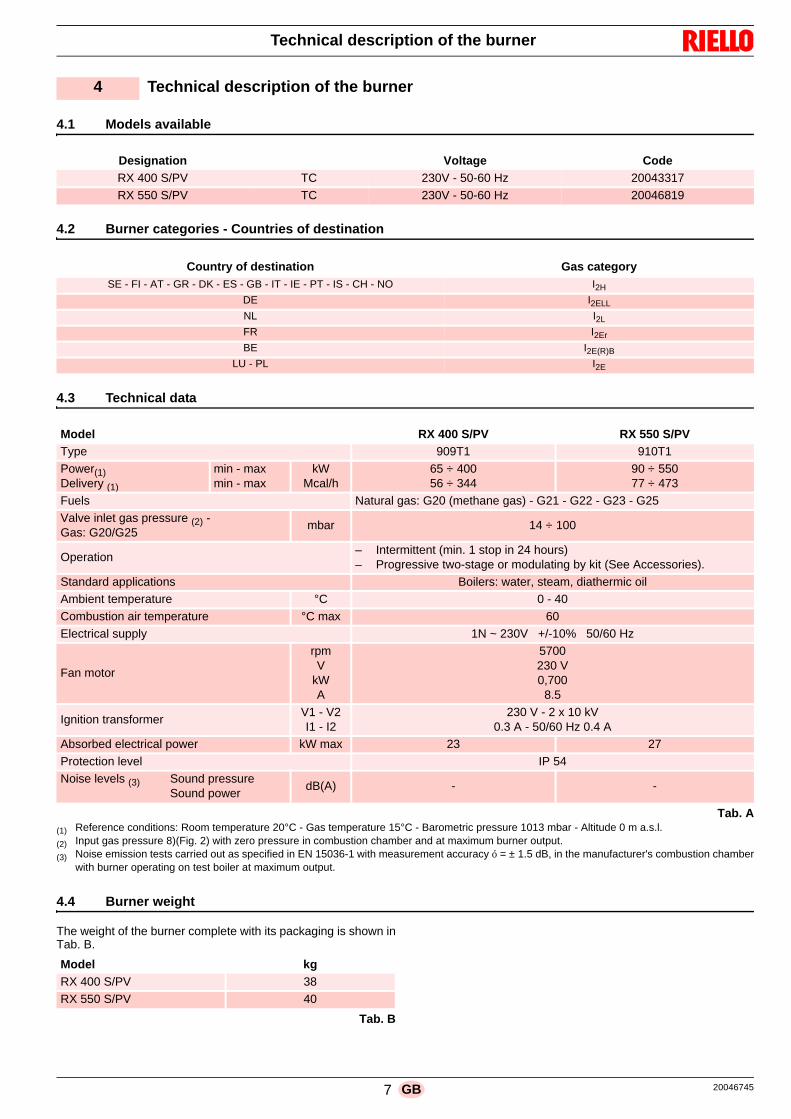
7 20046745GB
Technical description of the burner
4.1 Models available
4.2 Burner categories - Countries of destination
4.3 Technical data
Tab. A(1) Reference conditions: Room temperature 20°C - Gas temperature 15°C - Barometric pressure 1013 mbar - Altitude 0 m a.s.l.
(2) Input gas pressure 8)(Fig. 2) with zero pressure in combustion chamber and at maximum burner output.
(3) Noise emission tests carried out as specified in EN 15036-1 with measurement accuracy ó = ± 1.5 dB, in the manufacturer's combustion chamberwith burner operating on test boiler at maximum output.
4.4 Burner weight
The weight of the burner complete with its packaging is shown inTab. B.
Tab. B
4 Technical description of the burner
Designation Voltage Code
RX 400 S/PV TC 230V - 50-60 Hz 20043317
RX 550 S/PV TC 230V - 50-60 Hz 20046819
Country of destination Gas category
SE - FI - AT - GR - DK - ES - GB - IT - IE - PT - IS - CH - NO I2H
DE I2ELL
NL I2L
FR I2Er
BE I2E(R)B
LU - PL I2E
Model RX 400 S/PV RX 550 S/PV
Type 909T1 910T1
Power(1)Delivery (1)
min - maxmin - max
kWMcal/h
65 ÷ 40056 ÷ 344
90 ÷ 55077 ÷ 473
Fuels Natural gas: G20 (methane gas) - G21 - G22 - G23 - G25
Valve inlet gas pressure (2) - Gas: G20/G25
mbar 14 ÷ 100
Operation– Intermittent (min. 1 stop in 24 hours)– Progressive two-stage or modulating by kit (See Accessories).
Standard applications Boilers: water, steam, diathermic oilAmbient temperature °C 0 - 40
Combustion air temperature °C max 60
Electrical supply 1N ~ 230V +/-10% 50/60 Hz
Fan motor
rpmV
kWA
5700230 V0,700
8.5
Ignition transformerV1 - V2I1 - I2
230 V - 2 x 10 kV0.3 A - 50/60 Hz 0.4 A
Absorbed electrical power kW max 23 27
Protection level IP 54
Noise levels (3) Sound pressureSound power
dB(A) - -
Model kg
RX 400 S/PV 38
RX 550 S/PV 40
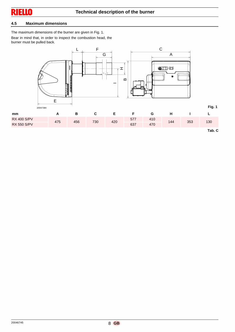
20046745 8 GB
Technical description of the burner
4.5 Maximum dimensions
The maximum dimensions of the burner are given in Fig. 1.
Bear in mind that, in order to inspect the combustion head, theburner must be pulled back.
Tab. C
H
E
L FG
I
A
B
C
Fig. 120047384
mm A B C E F G H I L
RX 400 S/PV475 456 730 420
577 410144 353 130
RX 550 S/PV 637 470
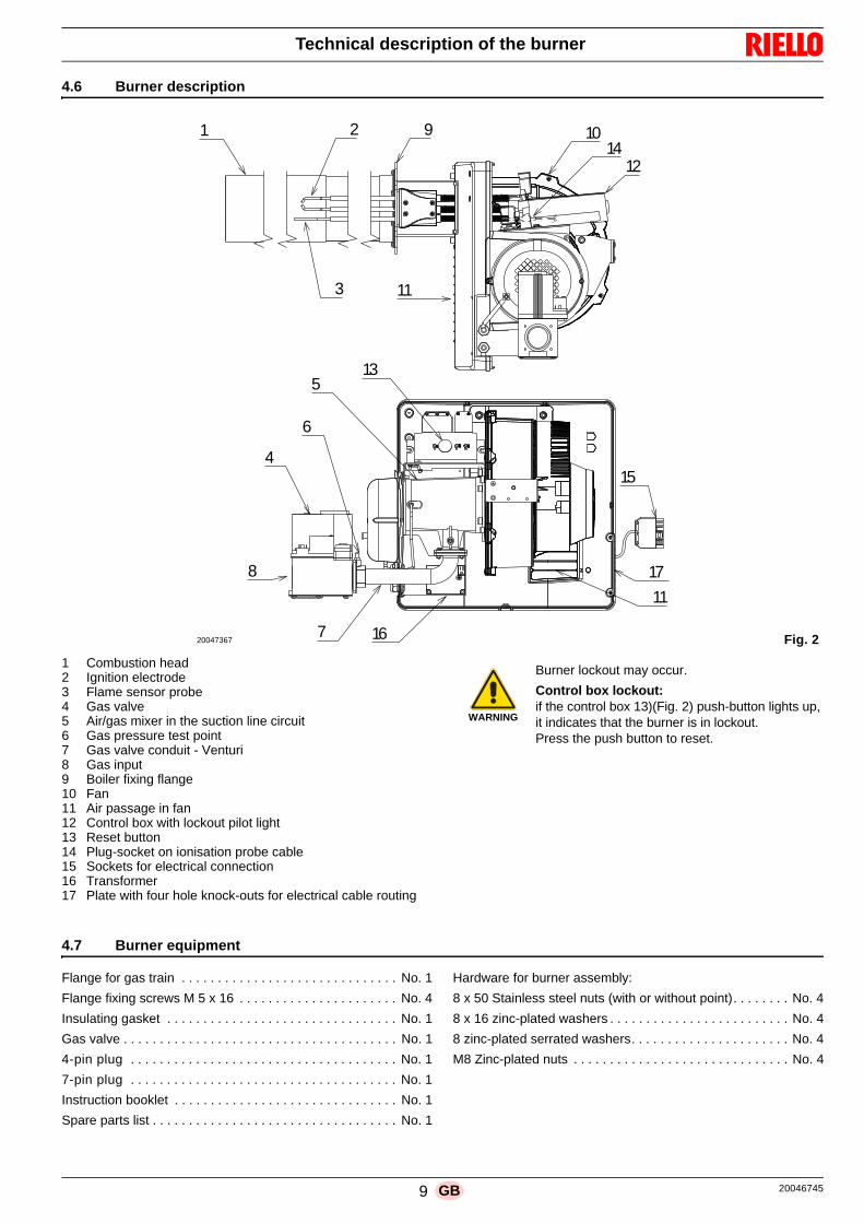
9 20046745GB
Technical description of the burner
4.6 Burner description
1 Combustion head2 Ignition electrode3 Flame sensor probe4 Gas valve5 Air/gas mixer in the suction line circuit 6 Gas pressure test point7 Gas valve conduit - Venturi 8 Gas input9 Boiler fixing flange10 Fan11 Air passage in fan12 Control box with lockout pilot light13 Reset button14 Plug-socket on ionisation probe cable 15 Sockets for electrical connection16 Transformer 17 Plate with four hole knock-outs for electrical cable routing
4.7 Burner equipment
Flange for gas train . . . . . . . . . . . . . . . . . . . . . . . . . . . . . . No. 1
Flange fixing screws M 5 x 16 . . . . . . . . . . . . . . . . . . . . . . No. 4
Insulating gasket . . . . . . . . . . . . . . . . . . . . . . . . . . . . . . . . No. 1
Gas valve . . . . . . . . . . . . . . . . . . . . . . . . . . . . . . . . . . . . . . No. 1
4-pin plug . . . . . . . . . . . . . . . . . . . . . . . . . . . . . . . . . . . . . No. 1
7-pin plug . . . . . . . . . . . . . . . . . . . . . . . . . . . . . . . . . . . . . No. 1
Instruction booklet . . . . . . . . . . . . . . . . . . . . . . . . . . . . . . . No. 1
Spare parts list . . . . . . . . . . . . . . . . . . . . . . . . . . . . . . . . . . No. 1
Hardware for burner assembly:
8 x 50 Stainless steel nuts (with or without point). . . . . . . . No. 4
8 x 16 zinc-plated washers . . . . . . . . . . . . . . . . . . . . . . . . . No. 4
8 zinc-plated serrated washers. . . . . . . . . . . . . . . . . . . . . . No. 4
M8 Zinc-plated nuts . . . . . . . . . . . . . . . . . . . . . . . . . . . . . . No. 4
4
5
6
7
8
11
13
17
16
15
1 2
3
9 10
11
1214
Fig. 220047367
WARNING
Burner lockout may occur.
Control box lockout: if the control box 13)(Fig. 2) push-button lights up,it indicates that the burner is in lockout.Press the push button to reset.

20046745 10 GB
Installation
5.1 Notes on safety for the installation
After carefully cleaning all around the area where the burner willbe installed, and arranging the correct lighting of the environ-ment, proceed with the installation operations.
5.2 Handling
The burner packaging includes a wooden platform, it is thereforepossible to move the burner (still packaged) with a transpallettruck or fork lift truck.
5.3 Preliminary checks
Checking the consignment
Checking the characteristics of the burner
Check the identification label of the burner (Fig. 3), showing:A the burner modelB the burner typeC the cryptographic year of manufactureD the serial numberE the data for electrical supply and the protection levelF the electrical power consumptionG the types of gas used and the relative supply pressuresH the data of the burner's minimum and maximum output pos-
sibilities (see Firing rate)Warning. The burner output must be within the boiler's firingrate;
I the category of the appliance/countries of destination.
5 Installation
DANGER
All the installation, maintenance and disassemblyoperations must be carried out with the electricitysupply disconnected.
WARNING
The installation of the burner must be carried outby qualified personnel, as indicated in this manualand in compliance with the standards and regula-tions of the laws in force.
DANGER
Combustion air inside the boiler must be free fromhazardous mixes (e.g.: chloride, fluoride, halo-gen); if present, it is highly recommended to carryout cleaning and maintenance more frequently.
WARNING
The handling operations for the burner can behighly dangerous if not carried out with the great-est attention: keep any unauthorised people at adistance; check the integrity and suitableness ofthe available means of handling.Check also that the area in which you are workingis empty and that there is an adequate escapearea (i.e. a free, safe area to which you can quick-ly move if the burner should fall).When handling, keep the load at not more than20-25cm from the ground.
After positioning the burner near the installationpoint, correctly dispose of all residual packaging,separating the various types of material.
CAUTION
Before proceeding with the installation operations,carefully clean all around the area where the burn-er will be installed.
CAUTION
After removing all the packaging, check the integ-rity of the contents. In the event of doubt, do notuse the burner; contact the supplier.
The packaging elements (wooden cage or card-board box, nails, clips, plastic bags, etc.) must notbe abandoned as they are potential sources ofdanger and pollution; they should be collected anddisposed of in the appropriate places.
WARNING
A burner label, or any other component, that hasbeen tampered with, removed or is missing, pre-vents the definite identification of the burner andmakes any installation or maintenance work diffi-cult
R.B.L.
GAS-KAASUGAZ-AEPIO
X
RIELLO S.p.A.I-37045 Legnago (VR)
AD E
B CF
I
G HG H
Fig. 3D10411
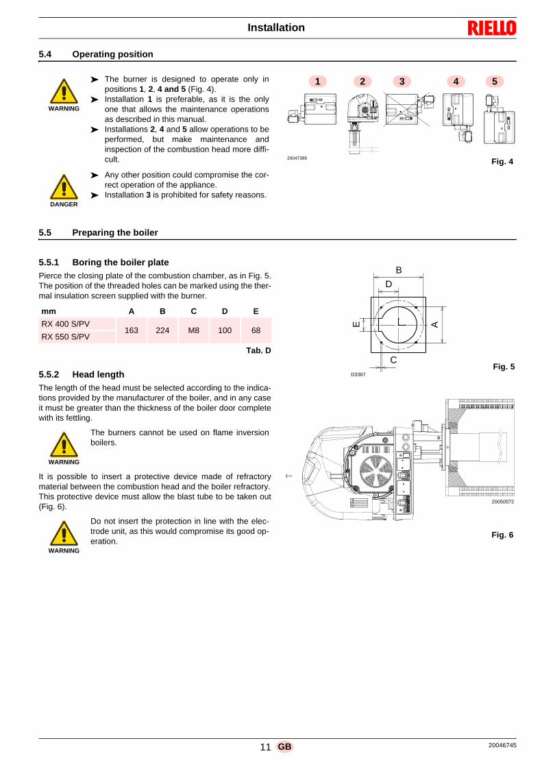
11 20046745GB
Installation
5.4 Operating position
5.5 Preparing the boiler
5.5.1 Boring the boiler plate
Pierce the closing plate of the combustion chamber, as in Fig. 5.The position of the threaded holes can be marked using the ther-mal insulation screen supplied with the burner.
Tab. D
5.5.2 Head length
The length of the head must be selected according to the indica-tions provided by the manufacturer of the boiler, and in any caseit must be greater than the thickness of the boiler door completewith its fettling.
It is possible to insert a protective device made of refractorymaterial between the combustion head and the boiler refractory.This protective device must allow the blast tube to be taken out(Fig. 6).
WARNING
The burner is designed to operate only inpositions 1, 2, 4 and 5 (Fig. 4).
Installation 1 is preferable, as it is the onlyone that allows the maintenance operationsas described in this manual.
Installations 2, 4 and 5 allow operations to beperformed, but make maintenance andinspection of the combustion head more diffi-cult.
DANGER
Any other position could compromise the cor-rect operation of the appliance.
Installation 3 is prohibited for safety reasons.
Fig. 4
2 3 4 51
20047389
mm A B C D E
RX 400 S/PV163 224 M8 100 68
RX 550 S/PV
WARNING
The burners cannot be used on flame inversionboilers.
WARNING
Do not insert the protection in line with the elec-trode unit, as this would compromise its good op-eration.
EC
B
D
A
Fig. 5D3367
Fig. 6
20050572
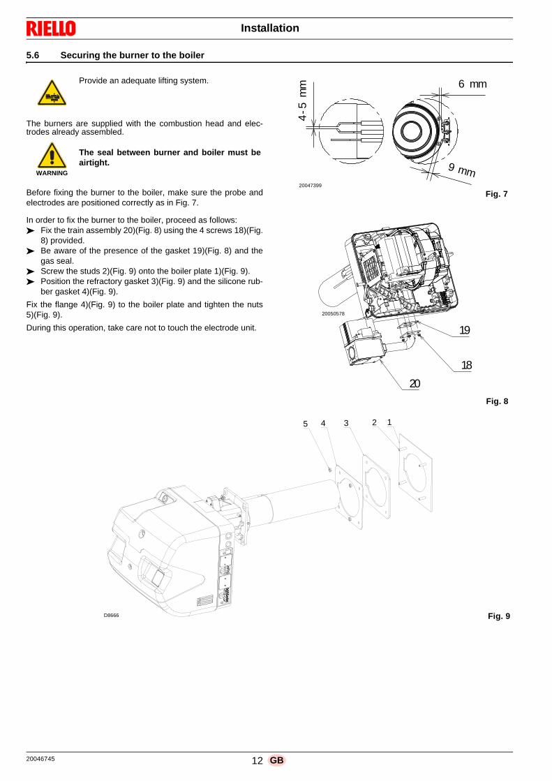
20046745 12 GB
Installation
5.6 Securing the burner to the boiler
The burners are supplied with the combustion head and elec-trodes already assembled.
Before fixing the burner to the boiler, make sure the probe andelectrodes are positioned correctly as in Fig. 7.
In order to fix the burner to the boiler, proceed as follows: Fix the train assembly 20)(Fig. 8) using the 4 screws 18)(Fig.
8) provided. Be aware of the presence of the gasket 19)(Fig. 8) and the
gas seal. Screw the studs 2)(Fig. 9) onto the boiler plate 1)(Fig. 9). Position the refractory gasket 3)(Fig. 9) and the silicone rub-
ber gasket 4)(Fig. 9).
Fix the flange 4)(Fig. 9) to the boiler plate and tighten the nuts5)(Fig. 9).
During this operation, take care not to touch the electrode unit.
Provide an adequate lifting system.
WARNING
The seal between burner and boiler must beairtight.
6 mm
9 mm
4-5
mm
20047399
Fig. 7
19
18
20
Fig. 8
20050578
12345
D8666 Fig. 9

13 20046745GB
Installation
5.7 Fuel supply
The burners are teamed with one-piece pneumatic proportioninggas valves, via which the amount of gas delivered, and hence theoutput produced, can be modulated.A signal reporting pressure detected in the air circuit is carried to
the pneumatic gas valve, which delivers an amount of gas in pro-portion to the airflow produced by the fan.
Air/gas mixer
Gas and combustive air are mixed inside the purging circuit (mix-er), starting from the intake inlet.
Through the gas train, fuel is introduced into the intake air currentand optimal mixing commences with the aid of a mixer.
NOTE:Pipe (T) between valve-Venturi allows compensation to oc-cur for accidental occlusion of the suction line due to a re-duction in gas delivered. After having connected thecompensation pipe (T) with the valve, cover it again with therubber protective device.
5.7.1 Gas train
This has been type-approved together with the burner, in accord-ance with regulation EN 676, and is supplied as standard (Fig.11).
Key (Fig. 11)1 Gas input pipe2 Manual valve3 Vibration damping joint4 Pressure gauge with pushbutton cock5 Valve including:
- filter (replaceable)- working valve- pressure adjuster
P1- Pressure upline the filterP2 Downstream pressure of valveL - Gas train suppliedL1 - The responsibility of the installer
Explosion danger due to fuel leaks in the pres-ence of a flammable source.
Precautions: avoid knocking, attrition, sparks andheat.
Make sure that the fuel interception tap is closedbefore performing any operation on the burner.
WARNING
The fuel supply line must be installed by qualifiedpersonnel, in compliance with current standardsand laws.
Fig. 10
D7803
Gas valve
Upstream
gas pressure
test point (P1)
Compensation pipe (T)
Metallic protective device
Fair lead
Compensation pipe (T)
Air/gas mixer(Venturi) in thesuction line circuit
Adjustment of maximum gas flow (V1)
Downstream pressure test point (P2)
Minimum gas flow
adjustment on the stabiliser (V2)
+-
+
-
Fig. 11
L1 L
VS VRRF
1 2 3
4 5
P2P1

20046745 14 GB
Installation
5.8 Burner operation
5.8.1 Adjustments prior to ignition
The following adjustments must be carried out:– open the manual valves upline of the gas train;– bleed the air from the gas pipes using the screw on the socket
(Fig. 10 on page 13).
5.8.2 Burner start-up
Close the thermostat and switch on the burner's power. The burn-er starts up in pre-purging mode at maximum speed. Subse-quently, the START value speed decreases and start-up occurs.If the fan starts up but at the end of the safety time the flame doesnot appear, burner goes into lockout mode. Reset and wait for anew start-up attempt. If ignition continues to not occur, it may bethe case that the gas is not arriving at the combustion head withinthe safety time of 3s.Rotate the screw V1, located on the gas valve mixer, slightly in ananti-clockwise direction (Fig. 13).Once the burner has fired, proceed with the global adjustment ofthe burner.
5.8.3 Fan adjustment
Modulation is based on variable-speed technology. Combustionair delivery can be adjusted by varying the motor's speed (rpm).The proportioning gas train delivers the right amount of fuel, de-pending on the pressure detected in the purging circuit. Hencethe output delivered is adjusted by varying the motor's speed ofrotation. The speed of the motor can be adjusted by means ofthree “Trimmers” (Fig. 12).
5.8.4 Gas valve adjustment
The adjustment of the output of gas is achieved by using the twoscrews V1 and V2.To alter the maximum output of gas use screw V1:– To increase the output: turn the screw anticlockwise (un-
screw);– to reduce the output: turn the screw clockwise (tighten).
To alter the minimum output of gas act on the screw V2 on thegas valve.
Remove the protection screw and act on the intern screws with ahex key:– To increase the output: turn the screw clockwise (tighten);– To reduce the output: turn the screw anticlockwise (unscrew).
Definition of the adjustments for the fan.
The adjustments are carried out by means on three potentiome-ters on board of the motor control box
START: determines the air in the start phase;MIN: determines the minimum modulation;MAX: determines the maximum modulation.
Fig. 12
MAX
STAR
T
MIN
Reset button
Maximum output Start
Minimum output
D7802
Fig. 13
Minimum gas flow adjustment on the stabiliser (V2)
Gas valve
Upstreamgas pressuretest point (P1)
Metallic protective device
Fair lead
Compensation pipe (T)
Adjustment of maximum gas flow (V1)
Downstream pressure test point (P2)
+-
+
-
D7803
Compensationpipe (T)
Air/gas mixer (Venturi) in the suction linecircuit

15 20046745GB
Installation
5.9 Electrical wiring
Notes on safety for the electrical wiring
Before carrying out any maintenance, cleaning or checking oper-ations:
If the cover is still present, remove it and proceed with the electri-cal wiring according to the wiring diagrams.
Use flexible cables in compliance with the EN 60 335-1 standard.
All the cables to be connected to the burner must be threadedthrough cable grommets.The use of the cable grommets can take various forms by way ofexample we indicate the following mode:
RX 400 S/PV1- 7 pole socket for single phase power supply, ther-
mostat/pressure switch TL2- 4 pole socket, thermostat/pressure switch TR3- 2-pole socket for device enabling the remote reset
of control box 4 - 4A Fittings for pipe unions
(Drill if 6A pipe unions are required )5 - 2-pin plugs for 0-10 Volt command.
RX 550 S/PV1- 7 pole socket for single phase power supply, ther-
mostat/pressure switch TL2- 4 pole socket, thermostat/pressure switch TR
3- 2-pole socket for device enabling the remote resetof control box
4 - 4A Fittings for pipe unions(Drill if 6A pipe unions are required)
5 - 2-pin plugs for 0-10 Volt command.
DANGER
The electrical wiring must be carried out with the electrical supply disconnected. Electrical wiring must be made in accordance with the regulations currently in force in the country of destination
and by qualified personnel. Refer to the wiring diagrams. The manufacturer declines all responsibility for modifications or connections different from those shown in the wir-
ing diagrams. Check that the electrical supply of the burner corresponds to that shown on the identification label and in this man-
ual. The burner has been type-approved for intermittent use.
This means they should compulsorily be stopped at least once every 24 hours to enable the control box to per-form checks of its own start-up efficiency. Normally, burner stopping is guaranteed by the boiler's thermostat/pres-sure switch.
If this is not the case, a time switch should be fitted in series to TL to stop the burner at least once every 24 hours.Refer to the wiring diagrams.
The electrical safety of the device is obtained only when it is correctly connected to an efficient earthing system,made according to current standards. It is necessary to check this fundamental safety requirement. In the event ofdoubt, have the electrical system checked by qualified personnel. Do not use the gas tubes as an earthing systemfor electrical devices.
The electrical system must be suitable for the maximum power absorption of the device, as indicated on the labeland in the manual, checking in particular that the section of the cables is suitable for that level of power absorp-tion.
For the main power supply of the device from the electricity mains:- do not use adapters, multiple sockets or extensions;- use a multiple pole switch with at least a 3mm gap between the contacts (overvoltage category III), as envis-
aged by the present safety standards. Do not touch the device with wet or damp body parts and/or in bare feet. Do not pull the electric cables.
DANGER
Disconnect the electrical supply from the burnerby means of the main system switch;.
DANGER
Close the fuel interception tap.
DANGER
Avoid condensate, ice and water leaks from form-ing.
After carrying out maintenance, cleaning orchecking operations, reassemble the hood and allthe safety and protection devices of the burner.
2
14
53
Fig. 14
D10842
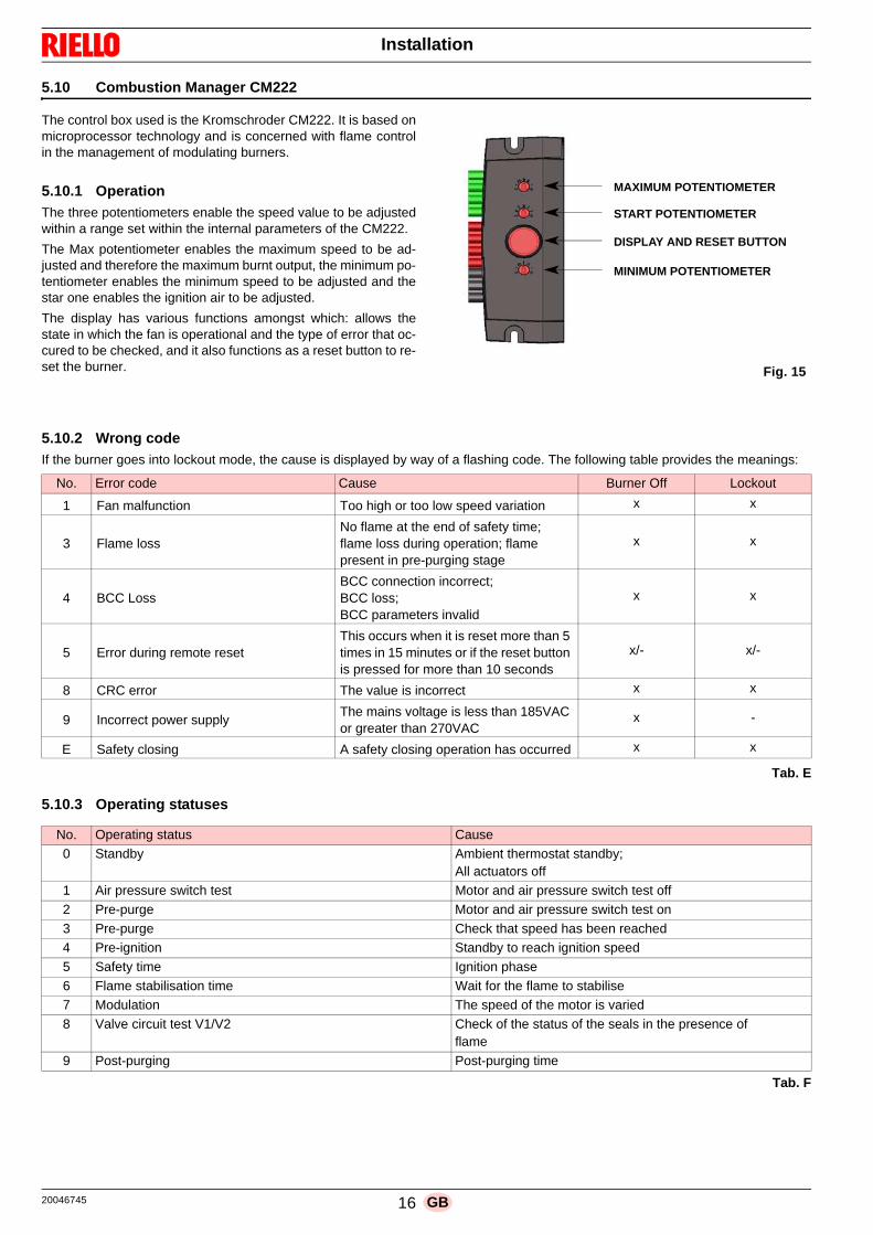
20046745 16 GB
Installation
5.10 Combustion Manager CM222
The control box used is the Kromschroder CM222. It is based onmicroprocessor technology and is concerned with flame controlin the management of modulating burners.
5.10.1 Operation
The three potentiometers enable the speed value to be adjustedwithin a range set within the internal parameters of the CM222.
The Max potentiometer enables the maximum speed to be ad-justed and therefore the maximum burnt output, the minimum po-tentiometer enables the minimum speed to be adjusted and thestar one enables the ignition air to be adjusted.
The display has various functions amongst which: allows thestate in which the fan is operational and the type of error that oc-cured to be checked, and it also functions as a reset button to re-set the burner.
5.10.2 Wrong code
If the burner goes into lockout mode, the cause is displayed by way of a flashing code. The following table provides the meanings:
Tab. E
5.10.3 Operating statuses
Tab. F
Fig. 15
MAXIMUM POTENTIOMETER
START POTENTIOMETER
DISPLAY AND RESET BUTTON
MINIMUM POTENTIOMETER
No. Error code Cause Burner Off Lockout
1 Fan malfunction Too high or too low speed variation x x
3 Flame lossNo flame at the end of safety time; flame loss during operation; flame present in pre-purging stage
x x
4 BCC LossBCC connection incorrect; BCC loss; BCC parameters invalid
x x
5 Error during remote resetThis occurs when it is reset more than 5 times in 15 minutes or if the reset button is pressed for more than 10 seconds
x/- x/-
8 CRC error The value is incorrect x x
9 Incorrect power supplyThe mains voltage is less than 185VAC or greater than 270VAC
x -
E Safety closing A safety closing operation has occurred x x
No. Operating status Cause
0 Standby Ambient thermostat standby; All actuators off
1 Air pressure switch test Motor and air pressure switch test off
2 Pre-purge Motor and air pressure switch test on
3 Pre-purge Check that speed has been reached4 Pre-ignition Standby to reach ignition speed
5 Safety time Ignition phase
6 Flame stabilisation time Wait for the flame to stabilise7 Modulation The speed of the motor is varied
8 Valve circuit test V1/V2 Check of the status of the seals in the presence of flame
9 Post-purging Post-purging time
17 20046745GB
Installation
5.10.4 Safety Parameters
Tab. G
BCC (CHIP CARD)
The BCC is a card onto which the operating parameters of theburner can easily be loaded via PC.
No. Parameter Min. Max. OEM-preset Value
1 pre-purging time 0.2 51 51 Seconds
2 Safety time 0.1 10 3 Seconds3 Flame stabilisation time 0.1 25.5 10 Seconds
4 Ignition attempts 1 5 3 Number
5 Post-purging time 0.2 51 0 Seconds6 Pre-ignition time 0.1 25.5 3 Seconds
7 Ignition time 0.1 25.5 3 Seconds
8 Post-purging speed 780 9960 1980 Rotations/min9 Maximum speed 780 9960 6000 Rotations/min
10 V1 Test time 0.1 25.5 1 Seconds
11 V1 Pulsetime 0.1 25.5 2 Seconds
12 V2 Test time 0.1 25.5 2.5 Seconds13 V2 Pulsetime 0.1 25.5 2 Seconds
14 Minimum limit maximum speed 780 9960 4020 Rotations/min
15 Maximum limit minimum speed 780 9960 2280 Rotations/min16 Pulses per rotation 1 4 3 Pulses/rotation
17 Frequency of the check of
speed
1 2 2 Hz
18 No airpress switch 0 1 - -
19 APS permanent test 0 1 - -
20 No feedback from motor 0 1 4 -21 No gas pressure switch 0 1 - -
22 Restart 0 1 - -
23 Gas valve check 0 1 4 -24 Seal valve test 0 1 - -

20046745 18 GB
Start-up, calibration and operation of the burner
6.1 Notes on safety for the first start-up
6.2 Burner adjustment
The optimum adjustment of the burner requires an analysis offlue gases at the generator outlet. In conformity with Boiler Effi-ciency Directive 92/42/EEC, the burner application at the gener-ator, the adjustment and the testing must be carried out incompliance with the instruction manual of the generator itself, in-cluding the control of the CO and CO2 concentration in the fluegases and of their temperature.
Check in sequence:
- MAX output;
- MIN output;
- ignition output.
Maximum output should match the value required by the boilerthat is used. To increase or decrease its value, adjust the trimmerMAX located on the control box Fig. 12 on page 14. Measure thegas delivery on the counter to precisely establish the burnt out-put.
Using a smoke analyser, measure the value of the CO2 or the O2in order to optimise the burner calibration. The correct values are: CO2 8.2 ÷ 9%.
To correct these values act on the gas valve in the following way:– to increase the gas delivery and the CO2: turn the screw V1
anticlockwise (unscrew);– to reduce the gas delivery and the CO2: turn the screw V1
clockwise (tighten).
Minimum output should match the value required by the boilerthat is used. To increase or decrease its value, adjust the trimmerMIN located on the control box Fig. 12 on page 14.
Measure the gas delivery on the counter to precisely establish theburnt output.
Using a smoke analyser, measure the value of the CO2 or the O2in order to optimise the burner calibration.
The correct values are: CO2 7.8 ÷ 8.5%.
To correct these values act on the gas valve in the following way:– to increase the gas delivery and the CO2: turn the screw V2
clockwise (tighten);– To reduce the gas delivery and the CO2: turn the screw V2
anticlockwise (unscrew).
6.2.1 Optimum calibration values
Tab. H
6 Start-up, calibration and operation of the burner
WARNING
The first start-up of the burner must be carried outby qualified personnel, as indicated in this manualand in compliance with the standards and regula-tions of the laws in force. WARNING
Check the correct working of the adjustment, com-mand and safety devices.
MIN output MAX output
CO2 (%) O2 (%) CO2 (%) O2 (%)
METHANE 8 6.6 8.5 5.7
LPG 9.5 6.4 10 5.6
Fig. 16D9714

19 20046745GB
Start-up, calibration and operation of the burner
6.2.2 Combustion headThe combustion head comprises a highly heat resistant cylinderwhose surface features numerous holes, encased in a metal"mesh". The air-gas mixture is pushed inside the cylinder and out of thehead through the holes in the perimeter. Combustion starts when the air-gas mixture is ignited by a sparkgenerated by the electrode. The metal "mesh" is the combustion head's most essential ele-ment since it improves burner performance considerably. The flame developed on the surface of the head is perfectly re-tained and adheres to the mesh when operating at the maximumsetting. This allows modulating ratios as high as 6:1, avoiding the dangerof flashback when modulating is at its minimum. The flame features an extremely compact geometry, meaningthat there is no risk of contact between the flame and parts of thegenerator, consequently eliminating the possible problem of poorcombustion. The flame's structure means that smaller combustion chamberscan be developed, designed to exploit this particular feature.
CAUTION
Before starting up the burner, it is good practice toadjust the gas train so that ignition takes place inconditions of maximum safety, i.e. with gas deliv-ery at the minimum.
m a x
m i n
t a r
s t
m a
t a r
s
m i n
tx
Fig. 17D9769

20046745 20 GB
Maintenance
7.1 Notes on safety for the maintenance
The periodic maintenance is essential for the good operation,safety, yield and duration of the burner.
It allows you to reduce consumption and polluting emissions andto keep the product in a reliable state over time.
Before carrying out any maintenance, cleaning or checking oper-ations:
7.2 Maintenance programme
7.2.1 Maintenance frequency
7.2.2 Checking and cleaning
CombustionThe optimum calibration of the burner requires an analysis of theflue gases. Significant differences with respect to the previous measure-ments indicate the points where most care should be exercisedduring maintenance.
Combustion headOpen the burner and make sure that all components of thecombustion head are in good condition, not deformed by thehigh temperatures, free of impurities from the surroundingsand correctly positioned.
BurnerCheck that there are not excess wear or loosen screws. Clean the outside of the burner.Clean and grease the adjustable profile of the cams.
FanCheck to make sure that no dust has accumulated inside the fanor on its blades, as this condition will cause a reduction in the airflow rate and provoke polluting combustion.
Ionisation current (Fig. 18)
The minimum current necessary for the control box operation is5 µA.
The burner normally supplies a higher current value, so that nocheck is needed.
Anyway, if you want to measure the ionisation current, you needto open the connector (CN1) fitted on the red wire and insert amicroammeter.
BoilerClean the boiler as indicated in its accompanying instructions inorder to maintain all the original combustion characteristics in-tact, especially the flue gas temperature and combustion cham-ber pressure.
Gas leaksMake sure that there are no gas leaks on the pipe between thegas meter and the burner.
Gas filterChange the gas filter when it is dirty.
7 Maintenance
DANGER
The maintenance interventions and the calibrationof the burner must only be carried out by qualified,authorised personnel, in accordance with the con-tents of this manual and in compliance with thestandards and regulations of current laws.
DANGER
Disconnect the electrical supply from the burnerby means of the main system switch.
DANGER
Close the fuel interception tap.
Wait for the components in contact with heatsources to cool down completely.
The gas combustion system should be checked atleast once a year by a representative of the man-ufacturer or another specialised technician.
The operator must use the required equipmentduring maintenance.
Fig. 18D5006
Probe
Connector
Control box

21 20046745GB
Maintenance
CombustionIn case the combustion values found at the beginning of the inter-vention do not respect the standards in force or, in any case, donot correspond to a proper combustion, contact the Technical As-sistant in order to carry out the necessary adjustments.
Tab. I
7.3 Opening and closing the burner
EN 676Air excess
COMax. output 1.2
Max. output 1.3
GASTheoretical max CO2
0 % O2
CO2 % Calibrationmg/kWh
= 1.2 = 1.3
G 20 11.7 9.7 9 1000
G 25 11.5 9.5 8.8 1000
G 30 14.0 11.6 10.7 1000
G 31 13.7 11.4 10.5 1000
DANGER
Disconnect the electrical supply from the burnerby means of the main system switch;.
DANGER
Close the fuel interception tap.
Wait for the components in contact with heatsources to cool down completely.
After carrying out maintenance, cleaning orchecking operations, reassemble the hood and allthe safety and protection devices of the burner.

20046745 22 GB
Appendix - Accessories
Output power regulator kit for modulating operation
Software diagnostics kit
A special kit is available that, by an optical link to a PC, shows the burner life together with operating hours, type and number of lock-outs, no. of motor rpm's and safety parameters.
To view diagnostics, proceed as follows: connect the kit (supplied separately) to the appropriate socket on the control box. Reading of the information begins when the
software programme included in the kit starts.
8 Appendix - Accessories
Output power regulator kit RWF40 With the modulating operation, the burner continually adapts the power to the heat request, ensuring a high level of stability for theparameter controlled: temperature or pressure.Two components should be ordered: • the output power regulator to be installed on the burner;• the probe to install on the heat generator.
Parameter to be checked Probe Output regulator
Adjustment field Type Code Type CodeTemperature - 100...+ 500°C PT 100 3010110
RWF40 3010212Pressure 0...2.5 bar
0...16 barOutput probe
4...20mA30102133010214
Burner Code
RX 400 S/PVRX 550 S/PV
20044365
WARNING
The installer is responsible for the addition of anysafety device not foreseen in this manual.
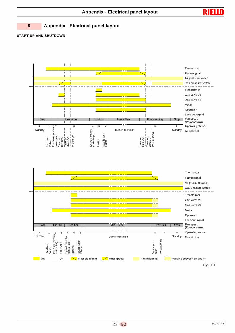
23 20046745GB
Appendix - Electrical panel layout
START-UP AND SHUTDOWN
9 Appendix - Electrical panel layout
APS-Supervision: No APS GPS-Supervision: ActiveValve-Supervision: Tightness control Behaviour after flame loss: Restart
Heat demand
Flame signal
Air pressure switch
Gas pressure switch
Ignition device
Gas valve V1
Gas valve V2
Fan
Operation
Fault signal
Fan speed
1 2 4 5 6 7
Sta
ndst
ill c
heck
Pre
purg
e ch
eck
Pul
setim
e V
1
Che
cktim
e V
2
Pre
purg
e
Wai
ting
for
igni
tion
spee
d
igni
tion
Fla
me
stab
iliza
tion
Pul
setim
e V
2
Che
cktim
e V
1
Pos
tpur
ge
APS-Supervision: No APS GPS-Supervision: ActiveValve-Supervision: Gas valve circuit check Behaviour after flame loss: Restart
Heat demand
Flame signal
Air pressure switch
Gas pressure switch
Ignition device
Gas valve V1
Gas valve V2
Fan
Operation
Fault signal
Fan speed
1 2 3 4 5 6 8
Sta
ndst
ill c
heck
Pre
purg
e ch
eck
Pre
purg
e
Wai
ting
for
igni
tion
spee
d
igni
tion
Fla
me
stab
iliza
tion
Gas
val
ve c
ircui
t ch
eck
On Off Must disappear Must appear Don´t care Alternately on
Inpu
tsO
utpu
ts
Standby
9
Inpu
tsO
utpu
ts
Postpurge
Program step / MessageStandby
0
Normal operation: Start-up and shut down
3
Burner operation
Normal operation: Start-up and shut down
0
Stop StopIgnition *Prepurge Min. - Max.
Stop Prepurge Ignition *
7 9 0
Min. - Max.
Program step / MessageStandby Burner operation
Pos
tpur
ge Standby
Postpurge Stop
0
Thermostat
Flame signal
Air pressure switch
Gas pressure switch
Transformer
Gas valve V1
Gas valve V2
Motor
Operation
Lock-out signal
Fan speed(Rotations/min.)Operating status
Description
Stop Pre-purge Ignition Min. - Max. Post-purging Stop
Sea
l tes
t
Pre
-pur
ge
Tim
e fo
r
Spe
ed S
tand
byof
sta
rt-u
p
Igni
tion
Sta
bilis
atio
nF
lam
e
Burner operation
Tim
e fo
r
Tim
e fo
r
Tim
e fo
r
Pos
t-pu
rgin
g
Standby Standby
Thermostat
Flame signal
Air pressure switch
Gas pressure switch
Transformer
Gas valve V1
Gas valve V2
Motor
Operation
Lock-out signal
Fan speed(Rotations/min.)
Operating status
Description
Stop Pre-pur. Ignition Min. - Max. Post-pur. Stop
Sea
l tes
t
Pre
-pur
ge (p
ress
ure
switc
h te
st)
Pre
-pur
ge
Spe
ed S
tand
byof
sta
rt-u
p
Igni
tion
Sta
bilis
atio
nF
lam
e
Burner operation Standby Standby
Val
ve g
as
Pos
t-pu
rgin
g
On Off Must disappear Must appear Non-influential Variable between on and off
Val
ve
switc
h te
st)
Pre
-pur
ge (p
ress
ure
blin
ks V
1
chec
k V
2
blin
ks V
2
chec
k V
1
Val
ve
test
Fig. 19
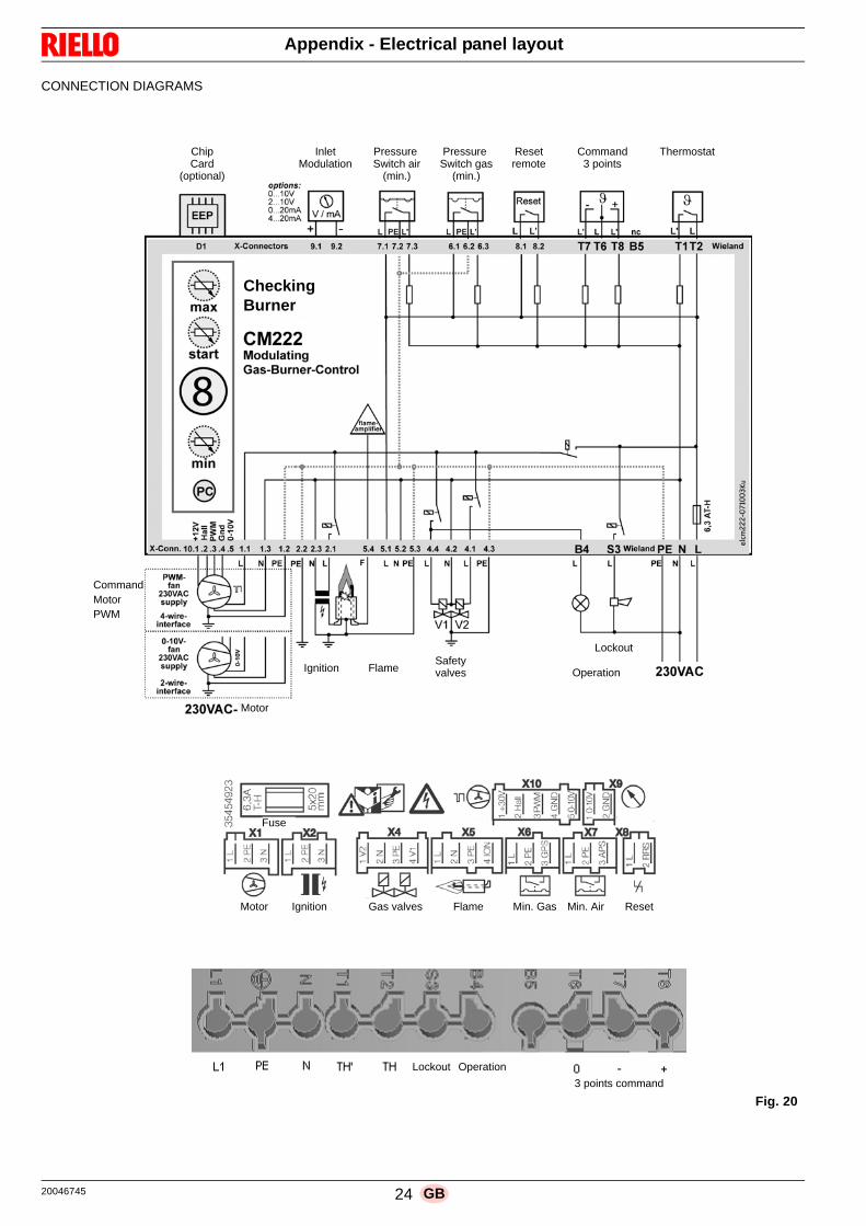
20046745 24 GB
Appendix - Electrical panel layout
CONNECTION DIAGRAMS
Motor Ignition Gas valves Flame Min. Gas Min. Air Reset
Lockout
Chip InletCard
(optional)Modulation
Pressure Switch air
Pressure Switch gas
Resetremote
(min.) (min.)
Command3 points
Thermostat
CheckingBurner
Ignition FlameSafetyvalves Operation
Lockout
Fuse
Operation
3 points command
Motor
CommandMotorPWM
Fig. 20

25 20046745GB
Appendix - Electrical panel layout
Index of layouts
2 Indication of references
3 Functional diagram
4 Functional diagram
5 Electrical wiring that the installer is responsible for
6 Functional layout RWF40
1
2
Sheet no.
/1.A1
Coordinates
Indication of references

20046745 26
���������
��
��
�
�
��
�
�
���
��
���� ��
�
��
��
��
��
���
��
��
��
�
��
�
��
��
���
�
��
��
��
�
��
��
��
�
��
� � � � !
� � � � !
�������!"�#������
��������������$�"�
��������������
�������!����������
%�������
�����
��
��
��
��
��
��
��
��
��
��
��
��
��
��
&�'��
��
�
��
�
��������
!�����
�%�������
������
���
��
� �
(�� (��
��
��
(��
(��
�&�&�������)*��)�+
�"�
�
%�$��
���
��
���
��
���
��
���
��
���
��
(��
���
��
� �
�
���
��
&�'��
�� ��
��&�'��
'
��)*
��),*
��
-
�"�.���"�&���"��&����"�&����"
���.������&�������&������&����/��#
$��.�%������&�$����/�&�0�"���&�%���
%��.�*�� ��&�%�����&�*����&�%�1�
� �.�������&��� �&���"%��&����
/��.��������&�/
�����&�������&�/
����
�%.���������&�����%��&�����%��&�����%�
*�.�*��������&�*������&�*������&�*������
%$.�%��%���&�%��$�&�%����&�%��"
��.������&������&������&�����
% .�����&�%�� �&����&�%��
��.��"�������&��"��"�����&��"��"�����&��"�������"
��.���%�����&����*���&���%����&�������
%�$�.�%�����&*�� ��&�$����/&%�����&�0�"��&*����&�%���&%�"�
���.���������&����/��&��������&����"�
��/�����)*��
���������
!���"��
�����%���������
���
%��
���
���
��
��
���
���
��
���
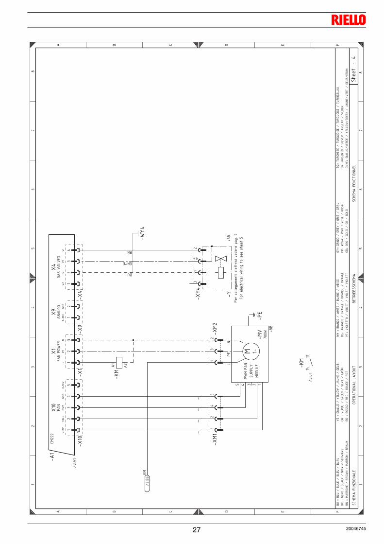
27 20046745
���������
��
� �
���
���
��
���
��
��
��
��
��
��
���
��
��
���
�
���
��
��
��
��
��
��
��
��
� � � � � �
� � � � � �
�� �����!"
#$%"
�&�
% �'�($%"
�&�&�
�%!
(��('
$���
�� ���
�� �����%"
�($%""
�&
��)�*��
+��
&"
�
�����"
�!
&��%�
!&�
� � � �
��
��
��
�
�
����
�����
��
��
��
�)�*��
��"
��"� %
��'
��
�
�"�
&%,
��
,�����&�
��
��
��
��
)�*��
����
�
�-�./00�123�4�5��0���-5.5�6�7�-��821*��
�/-��0�.�-5.20�95-541��/�:���:������
�!� �
,"���
�"� �
+��
�
�!�;��&!�)��&!��)��&�!�)��&�
!��
�;�"�'%�)��&�
���)�"%$'�)��� ��'#
���;�,$�&&%�)���&&%��)�<�!"
��)�,�&�
,"�;���'���)�,'��"�)���'(�)�,'=
"'�
�;�'%�
�%�)�'���)�'%!
,��)�'%(
� �;��$�"�%�)��
$(��)��&�
"��)��
�$��
%,;��'�
"�$%�)�%'�
",��)�%'�
",��)�%'�
",�
�(;��$%&�((
%�)��$%&�(�)��$%&�(�)��$%&�((
,�;�,'
$,$%�)�,'���)�,'$��)�,'�
! �
;�'%
���)� $"��)�'%�
��)�'%�
�,�
;�%'
%�)�,%&��)�%'�)�,%&�
(>;�(!
'� ����)�(!'
>!%
$���)�(!'
>!%
$���)�(!'
�$��
&�!
�';��',
�"(%
�)��$&��'�)��',
�"(�)��$&��'
,"��;�,$�&&%)
��'���)���&&%�),'
��"�)�<�!"
�)��'(�)�,�&�)
,'!"
�"�;���''
%"��)��'%
�"�)���''
%"�)��'�
!"
�
�
�
�
+���
�&&
��
,"�
����
& �
"����
,"�
��
" �
��

20046745 28
���������
�� � ��
�
����
�� �� �
�
����������������
��
���
��
�
�!���"�����!#����$�%!&$���!�
���!���'()$���!�
)��
����
�*
' �
�+�,-.�/+01�
�-2�3�4-+�3-,
����
!'����
'�
�5
��
��
�
�5
��
��
�
�5
� " � & ( #
� " � & ( #
�!��()�%(���(�('�������$'��&(��6��������!'(
(�(�'������!��(��!����(�"��������('
(�(7'!������8��(��!%��������($'��$�9$#8�'(�
'���!'&(%(���:�(�'��$(�(##(�$:���'��6��������($'
;"� ;"�
�<�<�(�����������=
�� �
�(�����!�&����(''$!'(�%�)�(!('%��!
��()��('(������!��
�����%�)�(!�('%���� ���
��!!�(���(��
(������&6���(''$�($'�%�)�:!�('%��$(
��!���'��(���(��
�%�#���(�(��(��%�)�(!�('%����(�
�����('������� >��(�
� ��(
�
;"� ;"�
���
"�
;"""$�
��
��(
"��
��(���(�'�������(6��(������!��(�('��(�)�
�!�����'��������!��!���!��()�'(�)�
���'�������((&�&!��!��!��(��)�
%��&(%�'��������('�������('"��&(��)�
)��(�
;"�"� ;"�
5
�
�
�
�$����(�&���"�!��!���&����9�
'(%!(�'(�(�"$!�
"!$!��&(�&(��!��)(���&�����(
#('�(�!'$�)���(
;"�
��
?
;
"$�@�"�$�<�"�$(�<�"�($�<�"��$
"7�@��('!�<�"���7�<��!�'�<���� �'9
�(�@�)����!�<��(��! �<�A�$�(�<�)(�"
)��@��('&(�<�)'((��<��('�<�)'8�
'&�@�'!��!�<�'(&�<�'!$)(�<�'!
��@�"����!�<� ��(�<�"�����<� (���
!)@��'����!�<�!'��)(�<�!'��)(�<�!'��)(
�@���!�(!�<���!�(�<���!�(�<���!�(
)�@�)'�)�!�<�)'(��<�)'���<�)'�$
�7@�'!���<����7�<�'!�(�<�'!��
)&@�!'!�<�)!�&�<�!'�<�)!�&
�@�$'��(�(�<�$'�$!��(�<�$'�$!��(�<�$'7��"��$
�'@��')(�!�<�����('�<��')(��<����"('
)��(@�)����!<�('&(�<��(��! <)'((��<�A�$�(<�('�<�)(�"<)'$�
"��@�%�''!�(�<�"'! ��<�%�''!��<�"'�$�
��
�'

29 20046745
���
����
��
�
���
� �
�
��
����
����
� �
�
�
�
� �
�
����
���
�
� �
�
����
� �
�
����
�
�� !
"�
����
!#�
$�"
� �$
� �
�
��#�
!�%
&�"
� �$
� $#
&���
�'�
(���
)*�#
+++++
���)
� �
�
��
���,
� �
�
��#
���� ��
"�
��
#���
� �
�-
����
# ��
�� $
#&�
��"
��
#���
� �
�-
����
�!�%
&�"
� �$
� $#
&���
�'�
��
���#
���
�
� �
�
��.
��
�
��.
��
#���
� �
�-
����
���#
� $�
� $#
&��"
$%��
��#�
$��
�' �
�
�)
,�
/�
0
�)
,�
/�
0
" � � % � �
" � � % � �
��'�
!"
��&$
1 �$
"��
� �
��*+
++ �
��*+
++��#
� "
� �$
"��
�"-
�&�
���
���
��'�
!"
� �
��*+
++��
'�!
"��
�$��
�$$
���
���
*+++
�)��
���
�2��
3���
�����
�4��
���3
���5
���
���
*6��
����2
����
��
����
�����
7���
��8��
����
9���
�� $
��3�
�����
�:�2
����
���+
�$��
���2
����
���
���
�:
��2�
����
����
��)�
3����
��
����
6��
6��0
3����
���
3���
����
�:��
����
$�$�
����
�;"
� +
����
�2�3
8���
�����
����
39�5
���
���
*6�3
��2�
��<�
����
�
����
�2��
����
����
��8��
����
9���
9��
$��
����
����
:�2
����
��+
�����
7���
����
���:
�2��
����
+%�
�2��
��<�
����
��
����
�2��
����
����
����
����
:�2
���
��2�
=���
���2
����
���)
�3��
���
���
���6
��6
��0
3���
��
��3�
����
����
2���
�$�$
���$
$���
>�
����
.��
?��
39�7
�3�2
����
� �
��*�
�:��
���@
���
��
����
3���
����
����
� $�
9�3�
3�2�
����
:�2
����
����
2���
��A�
�+�
:��
���@
���
����
����
3�2�
����
:�2
���
� ��
2���
��A�
�+%�
��5�
�::
����
��9�
3��)
����
��
9�3�
��6�
�6�
�0=�
��
��3B
�<��
�$ �
'��"
$;��
�'��
���$
�?��
3��+
<��
���C
��7�
����
����
����
�@��
� �
��*6
�3��
���
����
����
2?��
���
$���
3���
:��
����
�:�2
���
2?��
����
����
���9
7�
+�
����
97�
��3�
����
����
����
����
����
���:
�2��
��2?
����
�� +
����
���:
�2��
����
�)��
<���
����
97�
���
3��
����
���
�0��
<���
����
97�
��:
92��
2��C
&$��
$$��
��%+
��
!�3
9���
��7�
�9��
9�*D
�E��
�)*:
"��
*D)E
���*
.�%
�
��
���0�
�/
�" F%�F%��
�� F%�F%��
����
���
����
<���
� ��
0/
��$
�;;$%
;�
#�
����
����
7���
���7
��<�
����
��23
9���
%��)
�.�G
�,*:
"
;�
�
!H
�!�
�H
!�
;�
�'
�$
(���
)*�#
+++++
;$
*G�*
.
;�
;��
�
&�
!�
!�
�
�
��
;��
!�
;��
#�
�)
#�
�++++
)*:
"#�
��**
�'
�'
% %
���
���
� ��
*�)*
:"
����
)*:
"�%
�
�
*�)*
:"
����
)*:
"�%
�
�
!�
!�
!�
!�
;�
&�
*��.
��*�
�*.
�%�
&�
*��.
��*�
�*.
�%�
;� �
!�!�
�
��
�
��
�&�I
���&
�G��
�&��
G��
��&�
G��
�"&
�5�I
�$�
��G
���"
�5�G
�$�
�G
���'
�"
1-
��I�
; "
����
G�-
����
��G
�J"
&$��
G�;
���
;$�I
�.�
%��G
�; �
�$�G
�.�
��G
�; K
$ %
�I�
����
�G�
�%�G
� �&
;��G
� ��
�'�
I��
"$�
��G
��'
���G
���"
$��G
���
���;
I�"
"$�
��G
�� "
$;��
G��
"$;
��G
�� "
$;�
.�I
�. �
����
��G
�. �
����
G�.
���
��G
�. �
����
;-I�
; ;
��G
�; �
-�G
�;
��G
�; "

I� �
�"�G
�# $
5�G
� ��
��G
� ��
";%
I��
��G
�;��
%�G
�� �
G�;
��%
�(I�
�& �
'���
�G��
& (&
� ��
�G��
& (&
� ��
�G��
& 5
���"
&�
I�"
;�$
���G
�� �
.�
�G�"
;�$
��G
�� �
��
;$-
�I�;
"��
�G.
� %�
�G�-
����
�G
; ��
$�G
�J"
&$�G
.�
��G
�;��
�G;
&$�$
�I�!
"
�$��
G��
��
$�G
�!"
�$
�G��
"&$
!H
���
*++++
+++++
��
&�
(�,
(
(��
-�
-)
��
�;
�"
%�
��
��
!�
��
$
!�
�
;��
;�
;�
&�
%)
;$%
�H
#�
����
:��
�9��
�
�9�2
�3��
��:
����
�9��
�2�
2���
����
���:
�:��
����
�)�?
����
����
9��
�2�
2���
��#�
����
��:
����
�2�
2���
����
���:
�:��
����
�,�?
����
����
9��
%���
���?
����
�9��
����
�9��
9�
#��=
��?
����
�9��
����
�9��
9�
%���
���?
����
����
�7��
�9��
9�
#��=
��?
����
����
�7��
�9��
9�

20046745 30
LEGENDA SCHEMI ELETTRICI
A1 - Apparecchiatura elettrica CM222B... - SondaB1 - Regolatore di potenza RWF40+BB - Componenti bordo bruciatori+BC - Componenti bordo caldaiaCN - Connettore sonda ionizzazioneG1 - Ingresso in tensione 0...10 V DCH - Segnalazione esterna di blocco bruciatoreh1 - Contaore di funzionamento bruciatoreKM - Relè motore ventilatoreIN - Interruttore ON/OFF bruciatoreION - Sonda di ionizzazioneMV - Motore ventilatorePE - Terra bruciatoreQ2 - Interuttore principaleRS - Pulsante di sblocco esterno bruciatoreTA - Trasformatore di accensioneTL - Termostato/pressostato di limiteTR - Termostato/pressostato di regolazioneTS - Termostato/pressostato di sicurezzaT6A - FusibileW - Cavi elettriciY - Rampa gasX... - Connettori XM... - Connettori motore ventilatoreXP4... - Prese a 4 poliXP7... - Prese a 7 poliXS71 - Spina 7 poliXS41 - Spina 4 poliXTA - Terra trasformatoreXTB - Terra mensola/bruciatoreXY4 - Connettore rampa gasXRWF - Morsettiera regolatore di potenza
WIRING LAYOUT KEY
A1 - Control box CM222B... - ProbeB1 - Internal power regulator RWF40+BB - Components on burner +BC - Components on boilerCN - Ionisation probe connectorG1 - Input in voltage 0...10 V DCH - Lock-out signal burner externalh1 - Hour counter of operating burnerKM - Fan motor relayIN - Contactor ON/OFF burnerION - Ionisation probeMV - Fan motorPE - Burner ground (earth) connectionQ2 - Contactor mainRS - Reset button external burnerTA - Ignition transformerTL - Limit thermostat/pressure switchTR - Safety thermostat/pressureTS - Adjustment thermostat/pressureT6A - FuseW - Electric cablesY - Gas trainX... - Connectors XM... - Connectors fan motorXP4... - 4 pole socketsXP7... - 7 pole socketXS71 - 7 pin plugXS41 - 4 pin plugXTA - Earth transformerXTB - Burner shelf/Burner earthXY4 - Connector gas trainXRWF - Output power regulator terminal strip


RIELLO S.p.A.
I-37045 Legnago (VR)
Tel.: +39.0442.630111
http:// www.riello.it
http:// www.rielloburners.com
Con riserva di modifiche - Subject to modifications