ri-scope ri-scope L ri-derma - gimaitaly.com · 03 Indice pagina 1. Importanti avvertenze da...
64
Gebrauchsanweisung Diagnostische Instrumente Instructions Diagnostic Instruments Mode d’ emploi Instruments diagnostiques Instrucciones para el uso Instrumentos diagnósticos Инструкция по эксплуатации Диагностические приборы Istruzioni per I’ uso Strumenti diagnostici ri-scope ® ri-scope ® L ri-derma ® eisung nstrumente ruments agnostiques ara el uso iagnósticos эксплуатации кие приборы uso nostici
Transcript of ri-scope ri-scope L ri-derma - gimaitaly.com · 03 Indice pagina 1. Importanti avvertenze da...
Gebrauchsanweisung
Diagnostische Instrumente
Instructions
Diagnostic Instruments
Mode d’ emploi
Instruments diagnostiques
Instrucciones para el uso
Instrumentos diagnósticos
Инструкция по эксплуатацииДиагностические приборы
Istruzioni per I’ uso
Strumenti diagnostici
ri-scope® ri-scope® Lri-derma®
eisung
nstrumente
ruments
agnostiques
ara el uso
iagnósticos
эксплуатациикие приборы
uso
nostici
02
Inhaltsverzeichnis
1. Wichtige Informationen zur Beachtung vor Inbetriebnahme 06
2. Batteriegriffe und Inbetriebnahme 06
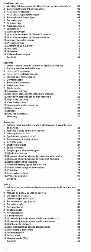
3. ri-scope®L Otoskope 08
4. ri-scope®L Ophthalmoskope 08
5. Retinoskope Slit und Spot 09
6. Dermatoskop 10
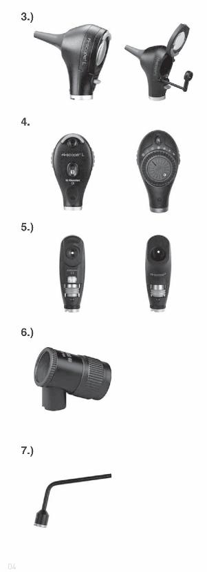
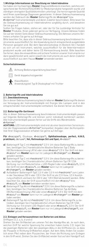
7. Lampenträger 10
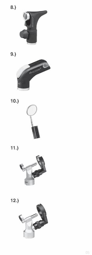
8. Nasenspekulum 10
9. Spatelhalter 10
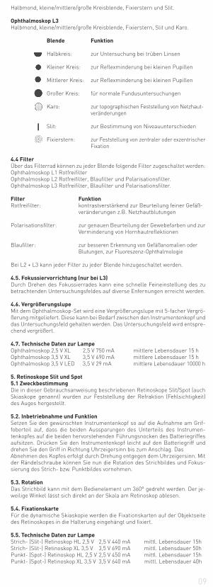
10. Kehlkopfspiegel 11
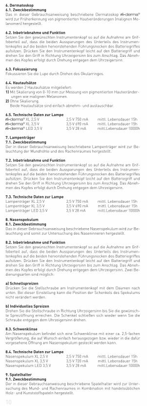
11. Operationsotoskop für Veterinärmedizin 11
12. Operationsotoskop für Humanmedizin 11
13. Auswechseln der Lampe 11
14. Pflegehinweise 12
15. Ersatzteile und Zubehör 12
16. Wartung 12
17. Hinweise 12
18. EMV-Anforderungen 12
Garantie 60
Contents
1. Important information to observe prior to initial use 15
2. Battery handles and initial use 15
3. ri-scope®L otoscope 17
4. ri-scope®L ophthalmoscope 17
5. Slit and spot retinoscopes 18
6. Dermatoscope 18
7. Bent-arm illuminator 19
8. Nasal speculum 19
9. Blade holder 19
10. Laryngeal mirrors 19
11. Operation otoscope for veterinary medicine 19
12. Operation otoscope for human medicine 20
13. Replacing the lamp 20
14. Care instructions 20
15. Spare parts and accessories 21
16. Maintenance 21
17. Notices 21
18. EMC requirements 21
Warranty 60
Sommaire
1. Informations importantes à lire attentivement avant la mise
en service 23
2. Manches à piles et mise en service 23
3. Otoscope ri-scope®L 25
4. Ophtalmoscope ri-scope®L 25
5. Rétinoscopes à trait et à spot 26
6. Dermatoscope 27
7. Support de lampe 27
8. Spéculum nasal 27
9. Support pour abaisse-langue 27
10. Miroir pour larynx 28
11. Otoscope chirurgical pour la médecine vétérinaire 28
12. Otoscope chirurgical pour la médecine humaine 28
13. Remplacement de la lampe 28
14. Entretien Nettoyage et désinfection 29
15. Pièces de rechange et accessoires 29
16. Entretien 29
17. Informations utiles 29
18. Prescriptions CEM 29
Garantie 60
Índice
1. Información importante a tener en cuenta antes de la puesta en
servicio 32
2. Mangos de pilas y puesta en servicio 32
3. Otoscopio ri-scope®L 34
4. Oftalmoscopio ri-scope®L 34
5. Retinoscopios raya y punto 35
6. Dermatoscopio 36
7. Portalámparas 36
8. Espéculo nasal 36
9. Portaespátulas 37
10. Laringoscopio 37
11. Otoscopio quirúrgico para medicina veterinaria 37
12. Otoscopio quirúrgico para medicina humana 37
13. Cambio de la lámpara 37
14. Recomendaciones para la conservación 38
15. Recambios y accesorios 38
16. Mantenimiento 38
17. Indicaciones 38
18. Requisitos de CEM 38
Garantía 61

03
Indice pagina
1. Importanti avvertenze da rispettare prima dell’uso 41
2. Manico portabatterie e messa in funzione 41
3. Otoscopio ri-scope®L 43
4. Oftalmoscopio ri-scope®L 43
5. Retinoscopio Slit e Spot (a linea e punto) 44
6. Dermatoscopio 44
7. Portalampadina 45
8. Specolo nasale 45
9. Porta abbassalingua 45
10. Laringoscopio 46
11. Otoscopio operatorio per lanmedicina veterinaria 46
12. Otoscopio operatorio per la medicina umana 46
13. Sostituzione della lampadina 46
14. Avvertenze per la cura dello strumento 47
15. Ricambi e accessori 47
16. Manutenzione 47
17. Avvertenze 47
18. Requisiti CEM 47
Garanzia 61
Cодержание1. Bажные указания перед вводом в действие 502. Аккумуляторные рукоятки и ввод в действие 503. Отоскоп ri-scope®L 524. Офтальмоскоп ri-scope®L 525. Pетиноскопы „полоса“ и „точка“ 536. Дерматоскоп 547. Держатель лампы 548. Hазальное зеркало 549. Держатель шпателя 5510. Гортанное зеркало 5511. Операционный отоскоп для ветеринарии 5512. Операционный отоскоп для медицины 5513. Замена лампы 5614. Указания по уходу 5615. Запасные части и принадлежности 5616. Tехническое обслуживание 5617. Указания 5618. Требования по 57 электромагнитной совместимости 61
04
05
06
1.Wichtige Informationen zur Beachtung vor Inbetriebnahme
Sie haben ein hochwertiges Riester DiagnostikBesteck erworben, welches ent-sprechend der Richtlinie93/42/EWG für Medizinprodukte hergestellt wurde und ständigen strengsten Qualitätskontrollen unterliegt. Die hervorragende Qualität wird Ihnen zuverlässige Diagnosen garantieren. In dieser Gebrauchsanweisung werden der Gebrauch der Riester Batteriegriffe der ri-scope® bzw. ri-derma® Instrumentenköpfe und deren Zubehör beschrieben. Bitte lesen Sie die Gebrauchsanweisung vor Inbetriebnahme sorgfältig durch, und bewahren Sie sie gut auf. Sollten Sie Fragen haben, stehen wir, oder der für Sie zuständige Vertreter für Riester Produkte, Ihnen jederzeit gerne zur Verfügung. Unsere Adresse finden Sie auf der letzten Seite dieser Gebrauchsanweisung. Die Adresse unseres Ver-treters erhalten Sie gerne auf Anfrage.Bitte beachten Sie, dass alle in dieser Gebrauchsanweisung beschriebenen In-strumente ausschließlich für die Anwendung durch entsprechend ausgebildete Personen geeignet sind. Bei dem Operationsotoskop im Besteck Vet-I handelt es sich um ein Instrument, welches ausschließlich für die Veterinärmedizin produziert wurde und daher keine CE-Kennzeichnung besitzt. Bitte beachten Sie ferner, dass die einwandfreie und sichere Funktion unserer Instrumente nur dann gewährleistet wird, wenn sowohl die Instrumente als auch deren Zubehör ausschließlich aus dem Hause Riester verwendet werden.
Sicherheitshinweise: Achtung Bedienungsanleitung beachten!
Gerät doppelschutzgeerdet
Klassifikation Anwendungsteil Typ B Otoskopkopf mit Trichter
2. Batteriegriffe und Inbetriebnahme
2.1. Zweckbestimmung
Die in dieser Gebrauchsanweisung beschriebenen Riester Batteriegriffe dienen zur Versorgung der Instrumentenköpfe mit Energie (die Lampen sind in den entsprechenden Instrumentenköpfen enthalten). Sie dienen ferner als Halter.
2.2. Batteriegriffe-Sortiment
Alle in dieser Gebrauchsanweisung beschriebenen Instrumentenköpfe passen auf folgende Batteriegriffe und können somit individuell kombiniert werden. Alle Instrumentenköpfe passen ferner auf die Griffe des Wandmodells ri-former®.ACHTUNG: LED Instrumentenköpfe sind erst ab einer bestimmten Seriennum-mer der Diagnosestation ri-former® kompatibel. Angaben über die Kompatibi-lität Ihrer Diagnosestation erhalten Sie gerne auf Anfrage.
Für ri-scope®L Otoskope, ri-scope®L Ophthalmoskope, perfect, H.N.O,
praktikant, de luxe®, Vet, Retinoskope Slit und Spot, ri-vision®
a) Batteriegriff Typ C mit rheotronic® 2,5 V. Um diese Batteriegriffe zu betrei- ben, benötigen Sie 2 handelsübliche Alkaline Batterien Typ C Baby (IECNormbezeichnung LR14) oder einen ri-accu® 2,5 V. Der Griff mit dem ri-accu® von Riester kann nur im Ladegerät ri-charger® von Riester geladen werden.b) Batteriegriff Typ C mit rheotronic® 3,5 V. Um diese Batteriegriffe zu betrei- ben, benötigen Sie 2 handelsübliche Lithium Batterien Typ CR 123A (Achtung: nur mit Reduzierhülse + LDO-Regler) oder einen ri-accu®L 3,5 V. Der Griff mit dem ri-accu®L von Riester kann nur im Ladegerät ri-charger®L von Riester geladen werden.c) Aufladbarer Batteriegriff TypC 2,5 V oder 3,5 V mit rheotronic® zum Laden in der Steckdose 230 V oder 120 V. Der Griff ist als 2,5 V bzw. 3,5 V Ausfüh- rung erhältlich und kann für 230 V oder 120 V Betrieb bestellt werden. Bitte beachten Sie, dass der Griff ausschließlich mit dem ri-accu® bzw. ri-accu®L von Riester betrieben werden kann.d) Batteriegriff Typ AA mit rheotronic® 2,5 V. Um diese Batteriegriffe zu betrei- ben, benötigen Sie 2 handelsübliche Alkaline Batterien Typ AA Baby (IECNormbezeichnung LR6) oder einen ri-accu® 2,5 V. Der Griff mit dem ri-accu® von Riester kann nur im Ladegerät ri-charger® von Riester ge- laden werden.e) Batteriegriff Typ AA mit rheotronic® 3,5 V. Um diese Batteriegriffe zu be- treiben, benötgen Sie 2 handelsübliche Lithium Batterien Typ CR 123A (Achtung nur mit einem LDO-Regler) oder einen ri-accu®L 3,5 V. Der Griff mit dem ri-accu®L von Riester kann nur im Ladegerät ri-charger®L von Riester geladen werden.
2.3. Einlegen und Herausnehmen von Batterien und Akkus
Grifftypen (2.2. a, b, d und e)Drehen Sie den Griffdeckel am unteren Teil des Handgriffes ab. Je nach dem, welchen Griff für welche Spannung Sie erworben haben (siehe 2.2), legen Sie die jeweiligen Batterien oder den jeweiligen Akku in die Griffhülse ein, so dass die Pluspole in Richtung Griffoberteil zeigen. Auf dem Akku finden Sie zusätz-lich einen Pfeil neben dem Pluszeichen, der Ihnen die Richtung zum Einlegen in den Griff weist. Drehen Sie den Griffdeckel wieder fest auf den Handgriff auf.

07
ACHTUNG: Bei Lithium Batterien (nur bei Batteriegriffe Typ C) benötigen Sie eine Reduzierhülse (Art. Nr.: 12652) + LDO-Regler (Art. Nr.: 12653)
Griff C
Bei Nachrüstung:
Drehen sie den Griffdeckel am unteren Teil des Handgriffes ab. Bei Lithium Batterien wird die Reduzierhülse mit dem Ende, wo der Federspannring sitzt, zuerst in die Griffhülse eingesetzt, der LDO-Regler wird in Richtung des aufge-druckten Pfeiles eingesetzt. Die Lithium Batterien werden so eingesetzt, dass die Pluspole in Richtung Griffoberteil zeigen. Drehen sie den Griffdeckel wieder fest auf den Handgriff auf.
Griff AA
Bei Nachrüstung:
Drehen sie den Griffdeckel am unteren Teil des Handgriffes ab. Bei Lithium Bat-terien wird der LDO-Regler in Richtung des aufgedruckten Pfeiles eingesetzt. Die Lithium Batterien werden so eingesetzt, dass die Pluspole in Richtung Grif-foberteil zeigen. Drehen Sie den Griffdeckel wieder fest auf den Handgriff auf.
Entnehmen Sie die Batterien, indem Sie zuerst den Batteriegriffdeckel abdre-hen und den Griff dann etwas schütteln.
Vor der ersten Inbetriebnahme müssen Akkus (im Batteriegriff von Riester) im Ladegerät ri-charger® von Riester aufgeladen werden. Jedem Ladegerät liegt eine extra Gebrauchsanweisung bei, die beachtet werden muss.
Grifftypen (2.2. c)
Vor der ersten Inbetriebnahme des Steckdosenhandgriffes sollte dieser in der Steckdose bis zu 24 Stunden lang aufgeladen werden.
ACHTUNG: Der Steckdosengriff (nur bei NiMH Akku´s) darf nicht länger als
24 Stunden aufgeladen werden.
Drehen Sie den Griffdeckel am unteren Teil des Handgriffes ab. Je nach dem, welchen Griff für welche Spannung Sie erworben haben (siehe 2.2) legen Sie die jeweiligen Akku´s in die Griffhülse ein. Achten Sie bei 2,5 V Akkus darauf, dass Sie den Akku mit der Plusseite in Richtung Griffoberteil in den Griff einlegen, neben dem Pluszeichen finden Sie zusätzlich einen Pfeil der Ihnen die Richtung zum einlegen in den Griff weist. Bei 3,5 V Akkus spielt es keine Rolle in welcher Richtung man sie einsetzt. Drehen Sie den Griffdeckel wieder fest auf denHandgriff auf.Drehen Sie das Griffunterteil entgegen dem Uhrzeigersinn ab. Die Steckdosen-kontakte werden sichtbar. Runde Kontakte sind für 230 V Netzbetrieb, flache Kontake sind für 120 V Netzbetrieb. Stecken Sie das Griffunterteil nun zum Auf-laden in die Steckdose.
ACHTUNG: Der Griff darf sich beim Auswechseln des Akkus niemals in der Steckdose befinden!Sollten Sie den ri-accu® auswechseln wollen, drehen Sie den Batteriegriffde-ckel am Unterteil des Griffes entgegen dem Uhrzeigersinn ab. Nehmen Sie den ri-accu® aus dem Batteriegriff heraus, indem Sie den Griff etwas nach unten schütteln. Legen Sie den ri-accu® in den Batteriegriff ein. Achten Sie bei 2,5 V Akkus darauf, dass Sie den Akku mit der Plusseite in Richtung Griffoberteil in den Griff einlegen, neben dem Pluszeichen finden Sie zusätzlich einen Pfeil der Ihnen die Richtung zum einlegen in den Griff weist. Bei 3,5 V Akkus spielt es keine Rolle in welcher Richtung man sie einsetzt. Drehen Sie den Batterieg-riffdeckel fest in Richtung Uhrzeigersinn auf den Griff auf. Technische Daten: Wahlweise 230 V oder 120 V
ACHTUNG:
• Sollten Sie das Gerät längere Zeit nicht benutzen oder auf Reisen mitneh- men, entfernen Sie bitte die Batterien und Akku´s aus dem Griff.• Neue Batterien sollten dann eingelegt werden, wenn die Lichtintensität des Instrumentes schwächer wird.• Um eine optimale Lichtausbeute zu erhalten, empfehlen wir, beim Batterie- wechsel immer neue hochwertige Batterien (wie in 2.2. beschrieben) einzu- legen.• Sollte der Verdacht bestehen, dass Flüssigkeit oder feuchter Beschlag in den Griff eingedrungen sein könnte, darf er auf keinen Fall aufgeladen wer- den. Insbesondere bei den Steckdosenhandgriffen kann dies zu einem le- bensgefährlichen elektrischen Schlag führen.• Um die Haltbarkeit des ri-accu® zu verlängern, sollte der ri-accu® erst dann aufgeladen werden, wenn die Lichtintensität des Instrumentes schwä- cher wird.
Entsorgung:
Bitte beachten Sie, dass Batterien und Akku´s speziell entsorgt werden müs-sen. Informationen hierzu erhalten Sie bei Ihrer Gemeinde bzw. bei Ihrem zu-ständigen Umweltberater/ in.
2.4. Aufsetzen von Instrumentenköpfen
Setzen Sie den gewünschten Instrumentenkopf so auf die Aufnahme am Grif-foberteil auf, dass die beiden Aussparungen des Unterteils des Instrumen-tenkopfes auf die beiden hervorstehenden Führungsnocken des Batteriegriffes aufsitzen. Drücken Sie den Instrumentenkopf leicht auf den Batteriegriff und drehen Sie den Griff in Richtung Uhrzeigersinn bis zum Anschlag. Das Abneh-men des Kopfes erfolgt durch Drehung entgegen dem Uhrzeigersinn.

08
2.5 Ein- und Ausschalten
Batteriegriffe Typ C und AA Schalten Sie das Instrument ein, indem Sie den Schaltring am Griffoberteil in Richtung Uhrzeigersinn antippen. Um das Inst-rument auszuschalten drücken Sie den Ring entgegen dem Uhrzeigersinn bis sich das Gerät ausschaltet.
2.6. rheotronic® zur Regulierung der Lichtintensität
Anhand der rheotronic® ist es möglich die Lichtintensität an den Batteriegrif-fen Typ C und AA einzustellen. Je nach dem, wie oft Sie den Schaltring entgegen oder in Richtung Uhrzeigersinn antippen, ist die Lichintensität schwächer oder stärker.ACHTUNG: Bei jedem Einschalten des Batteriegriffs ist die Lichtintensität bei 100% Automatische Sicherheitsabschaltung nach 180 Sekunden. Erläuterung des Zeichens am Steckdosenhandgriff: Achtung Bedienungsanleitung beachten!
3. ri-scope® L Otoskope
3.1. Zweckbestimmung
Das in dieser Gebrauchsanweisung beschriebeneRiester Otoskop wird zur Be-leuchtung und Untersuchung des Gehörganges in Kombination mit den Riester Ohrtrichtern produziert.
3.2. Aufsetzen und Abnehmen von Ohrtrichtern
Zur Bestückung des Otoskopkopfes können wahlweise Einmal-Ohtrichter von Riester (in schwarzer Farbe) oder wiederverwendbare Ohrtrichter von Riester (in schwarzer Farbe) gewählt werden. Die Größe des Ohrtrichters ist hinten am Trichter gekennzeichnet.
Otoskop L1 und L2
Drehen Sie den Trichter in Richtung Uhrzeigersinn bis ein Widerstand spürbar wird. Um den Trichter abnehmen zu können, drehen Sie den Trichter gegen den Uhrzeigersinn ab.
Otoskop L3
Setzen Sie den gewählten Trichter auf die verchromte Metallfassung des Otos-kopes bis er spürbar einrastet. Um den Trichter abnehmen zu können, drücken Sie die blaue Auswerfertaste. Der Trichter wird automatisch abgeworfen.
3.3. Schwenklinse zur Vergrößerung
Die Schwenklinse ist fest mit dem Gerät verbunden und kann um 360° ge-schwenkt werden.
3.4. Einführen
von externen Instrumenten ins Ohr Wenn Sie externe Instrumente ins Ohr einführen möchten (z.B. Pinzette), müssen Sie die Schwenklinse (ca. 3-fache Vergrößerung), welche sich am Otoskopkopf befindet, um 180° verdrehen. Sie können jetzt die Operationslinse einsetzen.
3.5. Pneumatischer Test
Um den pneumatischen Test (= eine Untersuchung des Trommelfells) durch-führen zu können, benötigen Sie einen Ball, der im normalen Lieferumfang nicht enthalten ist, aber zusätzlich bestellt werden kann. Der Schlauch des Bal-les wird auf den Anschluss gesteckt. Sie können nun die notwendige Luftmenge vorsichtig in den Ohrenkanal eingeben.
3.6. Technische Daten zur Lampe
Otoskop XL 2,5 V 2,5 V 750 mA mittl. Lebensdauer 15hOtoskop XL 3,5 V 3,5 V 720 mA mittl. Lebensdauer 15hOtoskop LED 3,5 V 3,5 V 28 mA mittl.Lebensdauer 10000h
4. ri-scope®L Ophthalmoskope
4.1. Zweckbestimmung
Das in dieser Gebrauchsanweisung beschriebene Riester Ophthalmoskop wird zur Untersuchung des Auges und des Augenhintergrundes hergestellt.
4.2. Linsenrad mit Korrekturlinsen
Die Korrekturlinsen können am Linsenrad eingestellt werden. Es stehen fol-gende Korrekturlinsen zur Auswahl:Ophthalmoskop L1 und L2Plus: 1-10, 12, 15, 20, 40.Minus: 1-10, 15, 20, 25, 30, 35.
Ophthalmoskop L3Plus: 1-45 in EinzelschrittenMinus: 1-44 in Einzelschritten
Die Werte können im beleuchteten Sichtfeld abgelesen werden. Pluswerte wer-den durch grün, Minuswerte durch rote Zahlen angezeigt.
4.3. Blenden
Über das Blendenstellrad können folgende Blenden gewählt werden:Ophthalmoskop L1
Halbmond, kleine/mittlere/große Kreisblende, Fixierstern, Slit.
Ophthalmoskop L2
09
Halbmond, kleine/mittlere/große Kreisblende, Fixierstern und Slit.
Ophthalmoskop L3
Halbmond, kleine/mittlere/große Kreisblende, Fixierstern, Slit und Karo.
Blende Funktion
Halbkreis: zur Untersuchung bei trüben Linsen Kleiner Kreis: zur Reflexminderung bei kleinen Pupillen Mittlerer Kreis: zur Reflexminderung bei kleinen Pupillen Großer Kreis: für normale Fundusuntersuchungen Karo: zur topographischen Feststellung von Netzhaut- veränderungen Slit: zur Bestimmung von Niveauunterschieden Fixierstern: zur Feststellung von zentraler oder exzentrischer Fixation
4.4 Filter
Über das Filterrad können zu jeder Blende folgende Filter zugeschaltet werden:Ophthalmoskop L1 RotfreifilterOphthalmoskop L2 Rotfreifilter, Blaufilter und Polarisationsfilter.Ophthalmoskop L3 Rotfreifilter, Blaufilter und Polarisationsfilter.
Filter Funktion
Rotfreifilter: kontrastverstärkend zur Beurteilung feiner Gefäß- veränderungen z.B. Netzhautblutungen
Polarisationsfilter: zur genauen Beurteilung der Gewebefarben und zur Verminderung von Hornhautreflektionen
Blaufilter: zur besseren Erkennung von Gefäßanomalien oder Blutungen, zur Fluoreszenz-Ophthalmologie
Bei L2 + L3 kann jeder Filter zu jeder Blende hinzugeschaltet werden.
4.5. Fokussiervorrichtung (nur bei L3)
Durch Drehen des Fokussierrades kann eine schnelle Feineinstellung des zu betrachtenden Untersuchungsfeldes auf diverse Enfernungen erreicht werden.
4.6. Vergrößerungslupe
Mit dem Ophthalmoskop-Set wird eine Vergrößerungslupe mit 5-facher Vergrö-ßerung mitgeliefert. Diese kann bei Bedarf zwischen den Instrumentenkopf und das Untersuchungsfeld gehalten werden. Das Untersuchungsfeld wird entspre-chend vergrößert.
4.7. Technische Daten zur Lampe
Ophthalmoskop 2,5 V XL 2,5 V 750 mA mittlere Lebensdauer 15 hOphthalmoskop 3,5 V XL 3,5 V 690 mA mittlere Lebensdauer 15 hOphthalmoskop 3,5 V LED 3,5 V 29 mA mittlere Lebensdauer 10000 h
5. Retinoskope Slit und Spot
5.1 Zweckbestimmung
Die in dieser Gebrauchsanweisung beschriebenen Retinoskope Slit/Spot (auch Skiaskope genannt) wurden zur Feststellung der Refraktion (Fehlsichtigkeit) des Auges hergestellt.
5.2. Inbetriebnahme und Funktion
Setzen Sie den gewünschten Instrumentenkopf so auf die Aufnahme am Grif-foberteil auf, dass die beiden Aussparungen des Unterteils des Instrumen-tenkopfes auf die beiden hervorstehenden Führungsnocken des Batteriegriffes aufsitzen. Drücken Sie den Instrumentenkopf leicht auf den Batteriegriff und drehen Sie den Griff in Richtung Uhrzeigersinn bis zum Anschlag. DasAbnehmen des Kopfes erfolgt durch Drehung entgegen dem Uhrzeigersinn. Mit der Rändelschraube können Sie nun die Rotation des Strichbildes und Fokus-sierung des Strich- bzw. Punktbildes vornehmen.
5.3. Rotation
Das Strichbild kann mit dem Bedienelement um 360° gedreht werden. Der je-weilige Winkel lässt sich direkt an der Skala am Retinoskop ablesen.
5.4. Fixationskarte
Für die dynamische Skiaskopie werden die Fixationskarten auf der Objektseite des Retinoskopes in die Halterung eingehängt und fixiert.
5.5. Technische Daten zur Lampe
Strich- (Slit-) Retinoskop HL 2,5 V 2,5 V 440 mA mittl. Lebensdauer 15hStrich- (Slit-) Retinoskop XL 3,5 V 3,5 V 690 mA mittl. Lebensdauer 50hPunkt- (Spot-) Retinoskop HL 2,5 V 2,5 V 450 mA mittl. Lebensdauer 15hPunkt- (Spot-) Retinoskop XL 3,5 V 3,5 V 640 mA mittl. Lebensdauer 40h
10
6. Dermatoskop
6.1. Zweckbestimmung
Das in dieser Gebrauchsanweisung beschriebene Dermatoskop ri-derma® wird zur Früherkennung von pigmentierten Hautveränderungen (malignen Me-lanomen) hergestellt.
6.2. Inbetriebnahme und Funktion
Setzen Sie den gewünschten Instrumentenkopf so auf die Aufnahme am Grif-foberteil auf, dass die beiden Aussparungen des Unterteils des Instrumen-tenkopfes auf die beiden hervorstehenden Führungsnocken des Batteriegriffes aufsitzen. Drücken Sie den Instrumentenkopf leicht auf den Batteriegriff und drehen Sie den Griff in Richtung Uhrzeigersinn bis zum Anschlag. Das Abneh-men des Kopfes erfolgt durch Drehung entgegen dem Uhrzeigersinn.
6.3. Fokussierung
Fokussieren Sie die Lupe durch Drehen des Okularringes.
6.4. Hautaufsätze
Es werden 2 Hautaufsätze mitgeliefert:1) Mit Skalierung von 0-10 mm zur Messung von pigmentierten Hautveränder- ungen wie malignen Melanomen.2) Ohne Skalierung. Beide Hautaufsätze sind einfach abnehm- und austauschbar.
6.5. Technische Daten zur Lampe
ri-derma® XL 2,5 V 2,5 V 750 mA mittl. Lebensdauer 15hri-derma® XL 3,5 V 3,5 V 690 mA mittl. Lebensdauer 15hri-derma® LED 3,5 V 3,5 V 28 mA mittl.Lebensdauer 10000h
7. Lampenträger
7.1. Zweckbestimmung
Der in dieser Gebrauchsanweisung beschriebene Lampenträger wird zur Be-leuchtung der Mundhöhle und des Rachenraumes hergestellt.
7.2. Inbetriebnahme und Funktion
Setzen Sie den gewünschten Instrumentenkopf so auf die Aufnahme am Grif-foberteil auf, dass die beiden Aussparungen des Unterteils des Instrumen-tenkopfes auf die beiden hervorstehenden Führungsnocken des Batteriegriffes aufsitzen. Drücken Sie den Instrumentenkopf leicht auf den Batteriegriff und drehen Sie den Griff in Richtung Uhrzeigersinn bis zum Anschlag. Das Abneh-men des Kopfes erfolgt durch Drehung entgegen dem Uhrzeigersinn.
7.3. Technische Daten zur Lampe
Lampenträger XL 2,5 V 2,5 V 750 mA mittl. Lebensdauer 15hLampenträger XL 3,5 V 3,5 V 690 mA mittl. Lebensdauer 15hLampenträger LED 3,5 V 3,5 V 28 mA mittl.Lebensdauer 10000h
8. Nasenspekulum
8.1. Zweckbestimmung
Das in dieser Gebrauchsanweisung beschriebene Nasenspekulum wird zur Be-leuchtung und somit zur Untersuchung des Naseninneren hergestellt.
8.2. Inbetriebnahme und Funktion
Setzen Sie den gewünschten Instrumentenkopf so auf die Aufnahme am Grif-foberteil auf, dass die beiden Aussparungen des Unterteils des Instrumen-tenkopfes auf die beiden hervorstehenden Führungsnocken des Batteriegriffes aufsitzen. Drücken Sie den Instrumentenkopf leicht auf den Batteriegriff und drehen Sie den Griff in Richtung Uhrzeigersinn bis zum Anschlag. Das Abneh-men des Kopfes erfolgt durch Drehung entgegen dem Uhrzeigersinn. Zwei Be-dienungsarten sind möglich:
a) Schnellspreizen
Drücken Sie die Stellschraube am Instrumentenkopf mit dem Daumen nach unten. Bei dieser Einstellung kann die Position der Schenkels des Spekulums nicht verändert werden.
b) Individuelles Spreizen
Drehen Sie die Stellschraube in Richtung Uhrzeigersinn bis Sie die gewünsch-te Spreizöffnung erreichen. Die Schenkel schließen sich wieder wenn Sie die Schraube entgegen dem Uhrzeigersinn drehen.
8.3. Schwenklinse
Am Nasenspekulum befindet sich eine Schwenklinse mit einer ca. 2,5-fachen Vergrößerung, die auf Wunsch einfach herausgezogen bzw. wieder in die dafür vorgesehene Öffnung am Nasenspekulum gesteckt werden kann.
8.4. Technische Daten zur Lampe
Nasenspekulum XL 2,5 V 2,5 V 750 mA mittl. Lebensdauer 15hNasenspekulum XL 3,5 V 3,5 V 720 mA mittl. Lebensdauer 15hNasenspekulum LED 3,5 V 3,5 V 28 mA mittl.Lebensdauer 10000h
9. Spatelhalter
9.1. Zweckbestimmung
Der in dieser Gebrauchsanweisung beschriebene Spatelhalter wird zur Unter-suchung des Mund- und Rachenraumes in Kombination mit handelsüblichen Holz- und Kunststoffspateln hergestellt.
11
9.2. Inbetriebnahme und Funktion
Setzen Sie den gewünschten Instrumentenkopf so auf die Aufnahme am Grif-foberteil auf, dass die beiden Aussparungen des Unterteils des Instrumen-tenkopfes auf die beiden hervorstehenden Führungsnocken des Batteriegriffes aufsitzen. Drücken Sie den Instrumentenkopf leicht auf den Batteriegriff und drehen Sie den Griff in Richtung Uhrzeigersinn bis zum Anschlag. DasAbnehmen des Kopfes erfolgt durch Drehung entgegen dem Uhrzeigersinn. Führen Sie einen handelsüblichen Holz- oder Kunststoffspatel in die Öffnung unterhalb des Lichtaustrittes bis zum Anschlag ein. Nach der Untersuchung kann der Spatel leicht entfernt werden, indem man den Auswerfer betätigt.
9.3. Technische Daten zur Lampe
Spatelhalter XL 2,5 V 2,5 V 750 mA mittl. Lebensdauer 15hSpatelhalter XL 3,5 V 3,5 V 720 mA mittl. Lebensdauer 15hSpatelhalter LED 3,5 V 3,5 V 28 mA mittl.Lebensdauer 10000h
10.Kehlkopfspiegel
10.1. Zweckbestimmung
Die in dieser Gebrauchsanweisung beschriebenen Kehlkopfspiegel werden zur Spiegelung bzw. Untersuchung des Mund- und Rachenraumes in Kombination mit dem Riester Lampenträger hergestellt.
10.2. Inbetriebnahme
Die Kehlkopfspiegel können nur in Kombination mit dem Lampenträger ver-wendet werden. Eine optimale Beleuchtung ist dadurch gewährleistet. Nehmen Sie einen der 2 Kehlkopfspiegel und stecken Sie ihn in der gewünschten Rich-tung vorne auf den Lampenträger auf.
11. Operationsotoskop für Veterinärmedizin
11.1. Zweckbestimmung
Das in dieser Gebrauchsanweisung beschriebene Riester Operationsotoskop wird ausschließlich zur Anwendung an Tieren bzw. für die Veterinärmedizin pro-duziert und besitzt deshalb keine CE-Kennzeichnung. Es kann zur Beleuchtung und Untersuchung des Gehörganges sowie für kleinere Operationen im Gehör-gang eingesetzt werden.
11.2. Aufsetzen und Abnehmen von Ohrtrichtern für Veterinärmedizin
Setzen Sie den gewünschten Trichter auf die schwarze Halterung am Operati-onsotoskop so auf, dass die Aussparung am Trichter in die Führung in der Hal-terung passt. Fixieren Sie den Trichter, indem Sie ihn im Uhrzeigersinn drehen.
11.3. Schwenklinse zur Vergrößerung
Am Operationsotoskop befindet sich eine kleine um 360° schwenkbare Vergrö-ßerungslinse mit einer ca. 2,5-fachen Vergrößerung.
11.4. Einführen von externen Instrumenten ins Ohr
Das Operationsotoskop ist offen gestaltet, so dass externe Instrumente ins tie-rische Ohr eingeführt werden können.
11.5. Technische Daten zur Lampe
Operationsotoskop HL 2,5 V 2,5V 680 mA mittl. Lebensdauer 20hOperationsotoskop XL 3,5 V 3,5V 700 mA mittl. Lebensdauer 20h
12. Operationsotoskop für Humanmedizin
12.1. Zweckbestimmung
Das in dieser Gebrauchsanweisung beschriebene Riester Operationsotoskop wird zur Beleuchtung und Untersuchung des Gehörganges sowie für das Ein-führen von externen Instrumenten in den Gehörgang produziert.
12.2 Aufsetzen und Abnehmen von Ohrtrichtern für Humanmedizin
Setzen Sie den gewünschten Trichter auf die schwarze Halterung am Operati-onsotoskop so auf, dass die Aussparung am Trichter in die Führung in der Hal-terung passt. Fixieren Sie den Trichter, indem Sie ihn im Uhrzeigersinn drehen.
12.3. Schwenklinse zur Vergrößerung
Am Operationsotoskop befindet sich eine kleine um 360° schwenkbare Vergrö-ßerungslinse mit einer ca. 2,5-fachen Vergrößerung.
12.4. Einführen von externen Instrumenten ins Ohr
Das Operationsotoskop ist so gestaltet, dass externe Instrumente ins Ohr ein-geführt werden können.
12.5. Technische Daten zur Lampe
Operationsotoskop HL 2,5 V 2,5 V 680 mA mittl. Lebensdauer 20hOperationsotoskop XL 3,5 V 3,5 V 700 mA mittl. Lebensdauer 20h
13. Auswechseln der Lampe
Otoskop L1
Nehmen Sie die Trichteraufnahme vom Otoskop ab. Drehen Sie die Lampe entgegen den Uhrzeigersinn heraus. Drehen Sie die neue Lampe in Richtung Uhrzeigersinn fest und setzen Sie die Trichteraufnahme wieder auf.
Otoskope L2, L3, ri-derma®, Lampenträger, Nasenspekulum und Spatelhal-
ter
Drehen Sie den Instrumentenkopf vom Batteriegriff ab. Die Lampe befindet sich unten im Instrumentenkopf. Ziehen Sie die Lampe mittels Daumen und Zeige-
12
finger oder eines geeigneten Werkzeuges aus dem Instrumentenkopf. Setzen Sie die neue Lampe fest ein.
Ophthalmoskope
Nehmen Sie den Instrumentenkopf vom Batteriegriff ab. Die Lampe befindet sich unten im Instrumentenkopf. Entnehmen Sie die Lampe mittels Daumen und Zeigefinger oder eines geeigneten Werkzeuges dem Instrumentenkopf. Setzen Sie die neue Lampe fest ein.
ACHTUNG: Der Stift der Lampe muss in die Führungsnut am Instrumentenkopf eingeführt werden.
Operationsotokope Veterinär/Human
Drehen Sie die Lampe aus der Fassung im Operationsotoskop und drehen Sie eine neue Lampe wieder fest ein.
14. Pflegehinweise
Allgemeiner Hinweis
Die Reinigung und Desinfektion der Medizinprodukte dient zum Schutz des Pa-tienten, des Anwenders und Dritter und zum Werterhalt der Medizinprodukte.Aufgrund des Produktdesigns und der verwendeten Materialien, kann kein de-finiertes Limit von max. durchführbaren Aufbereitungszyklen festgelegt wer-den. Die Lebensdauer der Medizinprodukte wird durch deren Funktion und den schonenden Umgang bestimmt.Defekte Produkte müssen vor Rücksendung zur Reparatur den beschriebenen Wiederaufbereitungsprozess durchlaufen haben.
Reinigung und Desinfektion
Die Instrumentenköpfe und Griffe können außen mit einem feuchten Tuch ge-reinigt werden bis optische Sauberkeit erreicht ist.Wischdesinfektion nach Vorgaben des Herstellers des Desinfektionsmittels. Es sollten nur Mittel mit nachgewiesener Wirksamkeit unter Berücksichtigung der Nationalen Anforderungen zur Anwendung kommen.Nach der Desinfektion Abwischen des Instrumentes mit einem feuchten Tuch um mögliche Desinfektionsmittelreste zu entfernen.
Die Hautaufsätze (ri-derma®) können mit Alkohol oder einem geeignetem Desinfektionsmittel abgerieben werden.Achtung!
• Legen Sie die Instrumentenköpfe und Griffe niemals in Flüssigkeiten! Achten Sie darauf, dass keine Flüssigkeiten ins Gehäuseinnere eindringen!• Der Artikel ist für maschinelle Aufbereitung und Sterilisation nicht freigege- ben. Es kommt hierbei zu irreparablen Schäden!
Sterilisation
a) Wiederverwendbare Ohrtrichter
Die Ohrtrichter können bei 134°C und 10 Minuten Haltezeit im Dampfsterili- sator sterilisiert werden.
b) Einmal Ohrtrichter
Nur zum Einmalgebrauch
Achtung: Bei mehrmaligem Gebrauch kann es zu einer Infektion kommen.
15. Ersatzteile und Zubehör
Eine detaillierte Auflistung finden Sie in unseremProspekt Instrumente für H.N.O. Ophthalmologische Instrumente, den Sie sich unter www.riester.de herunterladen können.
16. Wartung
Die Instrumente und deren Zubehör bedürfen keiner speziellen Wartung. Sollte ein Instrument aus irgendwelchen Gründen überprüft werden müssen, schi-cken Sie es bitte an uns oder an einen autorisierten Riester Fachhändler in Ihrer Nähe, den wir Ihnen auf Anfrage gerne benennen.
17. Hinweise
Umbegungstemperatur: 0° bis +40°Relative Luftfeuchtigkeit: 30% bis 70% nicht kondensierendTransport- und Lagertemperatur: -10° bis +55°Relative Luftfeuchte: 10% bis 95% nicht kondensierend
18 Elektromagnetische Verträglichkeit
Medizinische elektrische Geräte unterliegen hinsichtlich der elektromagneti-sche Verträglichkeit (EMV) besonderen Vorsichtsmaßnahmen.Tragbare und mobile Hochfrequenz-Kommunikations-Einrichtungen können medizinische elektrische Geräte beeinflussen. Da ME-Gerät ist für den Betrieb in einer wie unten angegebenen elektromagnetischen Umgebung bestimmt. Der Anwender des Gerätes sollte sicherstellen, dass es in einer deratrigen Um-gebung betrieben wird.Das ME-Gerät darf nicht unmittelbar neben oder mit anderen Geräten gesta-pelt angeordnet verwendet werden. Wenn der Betrieb nahe oder mit anderen Geräten gestapelt erforderlich ist, sollte das ME-Gerät beobachtet werden, um seinen bestimmungsgemäßen Betrieb in dieser Anordnung zu überprüfen. Die-ses ME-Gerät ist ausschließlich zum Gebrauch durch medizinische Fachkräfte vorgesehen. Dieses Gerät kann Funkstörungen hervorrufen oder kann den Be-
13
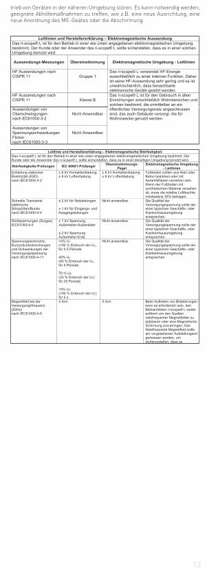
Leitlinie und Herstellererklärung – Elektromagnetische Störfestigkeit Das ri-scope® L ist für den Betrieb in einer wie unten angegebenen elektromagnetischen Umgebung bestimmt. Der Kunde oder der Anwender des ri-scope® L sollte sicherstellen, dass es in einer derartigen Umgebung benutzt wird.
Störfestigkeits-Prüfungen IEC 60601-Prüfpegel Übereinstimmungs-Pegel
Elektromagnetische Umgebung - Leitlinien
Entladung statischer Elektrizität (ESD) nach IEC61000-4-2
± 6 kV Kontaktentladung ± 8 kV Luftentladung
± 6 kV Kontaktentladung ± 8 kV Luftentladung
Fußböden sollten aus Holz oder Beton bestehen oder mit Keramikfliesen versehen sein. Wenn der Fußboden mit synthetischem Material versehen ist, muss die relative Luftfeuchte mindestens 30% betragen.
Schnelle Transiente elektrische Störgrößen/Bursts nach IEC61000-4-4
± 2 kV für Netzleitungen ± 1 kV für Eingangs- und Ausgangsleitungen
Nicht anwendbar Die Qualität der Versorgungsspannung sollte der einer typischen Geschäfts- oder Krankenhausumgebung entsprechen.
Stoßspannungen (Surges) IEC61000-4-5
± 1 kV Spannung Außenleiter-Außenleiter ± 2 kV Spannung Außenleiter-Erde
Nicht anwendbar Die Qualität der Versorgungsspannung sollte der einer typischen Geschäfts- oder Krankenhausumgebung entsprechen.
Spannungseinbrüche, Kurzzeitunterbrechungen und Schwankungen der Versorgungsspannung nach IEC61000-4-11
<5% UT (>95 % Einbruch der UT) für 0.5 Periode 40% UT (60 % Einbruch der UT) für 5 Periode 70 % UT (30 % Einbruch der UT) für 25 Periode <5% UT (>95 % Einbruch der UT) für 5 s
Nicht anwendbar
Die Qualität der Versorgungsspannung sollte der einer typischen Geschäfts- oder Krankenhausumgebung entsprechen
Magnetfeld bei der Versorgungsfrequenz (50Hz) nach IEC61000-4-8
3 A/m 3 A/m Beim Auftreten von Bildstörungen kann es erforderlich sein, den Bildverstärker ri-scope® L weiter entfernt von den Quellen netzfrequenter Magnetfelder zu platzieren oder eine Magnetische Schirmung anzubringen: Das Netzfrequente Magnetfeld sollte am vorgesehenen Aufstellungsort gemessen werden, um sicherzustellen, dass es
Leitlinien und Herstellererklärung – Elektromagnetische Aussendung Das ri-scope® L ist für den Betrieb in einer wie unten angegebenen elektromagnetischen Umgebung bestimmt. Der Kunde oder der Anwender des ri-scope® L sollte sicherstellen, dass es in einer solchen Umgebung benutzt wird.
Aussendungs-Messungen
Übereinstimmung
Elektromagnetische Umgebung - Leitlinien
HF Aussendungen nach CISPR 11
Gruppe 1
Das ri-scope® L verwendet HF-Energie ausschließlich zu einer internen Funktion. Daher ist seine HF-Aussendung sehr gering und es ist unwahrscheinlich, dass benachbarte elektronische Geräte gestört werden.
HF Aussendungen nach CISPR 11
Klasse B
Das ri-scope® L ist für den Gebrauch in allen Einrichtungen einschließlich Wohnbereichen und solchen bestimmt, die unmittelbar an ein
Aussendungen von Oberschwingungen nach EC61000-3-2
Nicht Anwendbar
öffentliches Versorgungsnetz angeschlossen sind, das auch Gebäude versorgt, die für Wohnzwecke genutzt werden.
Aussendungen von Spannungsschwankungen Flicker nach IEC61000-3-3
Nicht Anwendbar
trieb von Geräten in der näheren Umgebung stören. Es kann notwendig werden, geeignete Abhilfemaßnahmen zu treffen, wie z.B. eine neue Ausrichtung, eine neue Anordnung des ME-Geätes oder die Abschirmung.
14
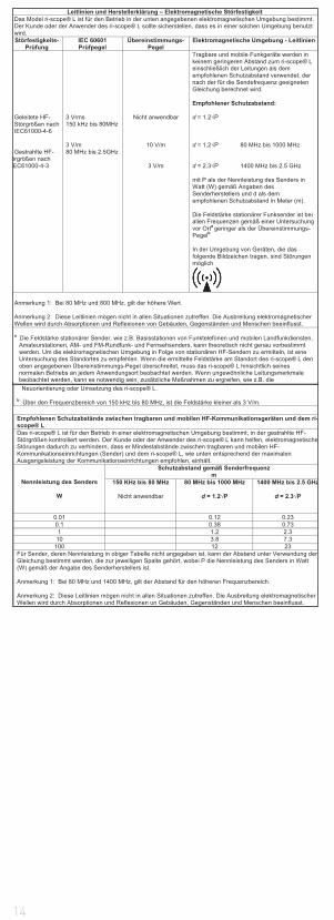
Neuorientierung oder Umsetzung des ri-scope® L. b Über den Frequenzbereich von 150 kHz bis 80 MHz, ist die Feldstärke kleiner als 3 V/m.
Empfohlenen Schutzabstände zwischen tragbaren und mobilen HF-Kommunikationsgeräten und dem ri-scope® L Das ri-scope® L ist für den Betrieb in einer elektromagnetischen Umgebung bestimmt, in der gestrahlte HF-Störgrößen kontrolliert werden. Der Kunde oder der Anwender des ri-scope® L kann helfen, elektromagnetischeStörungen dadurch zu verhindern, dass er Mindestabstände zwischen tragbaren und mobilen HF-Kommunikationseinrichtungen (Sender) und dem ri-scope® L, wie unten entsprechend der maximalen Ausgangsleistung der Kommunikationseinrichtungen empfohlen, einhält.
Nennleistung des Senders
W
Schutzabstand gemäß Senderfrequenz m
150 KHz bis 80 MHz
Nicht anwendbar
80 MHz bis 1000 MHz
d = 1.2 P
1400 MHz bis 2.5 GHz
d = 2.3 P
0.01 0.12 0.23 0.1 0.38 0.73 1 1.2 2.3
10 3.8 7.3 100 12 23
Für Sender, deren Nennleistung in obiger Tabelle nicht angegeben ist, kann der Abstand unter Verwendung der Gleichung bestimmt werden, die zur jeweiligen Spalte gehört, wobei P die Nennleistung des Senders in Watt (W) gemäß der Angabe des Senderherstellers ist. Anmerkung 1: Bei 80 MHz und 1400 MHz, gilt der Abstand für den höheren Frequenzbereich. Anmerkung 2: Diese Leitlinien mögen nicht in allen Situationen zutreffen. Die Ausbreitung elektromagnetischer Wellen wird durch Absorptionen und Reflexionen un Gebäuden, Gegenständen und Menschen beeinflusst.
Leitlinien und Herstellerklärung – Elektromagnetische Störfestigkeit Das Model ri-scope® L ist für den Betrieb in der unten angegebenen elektromagnetischen Umgebung bestimmt. Der Kunde oder der Anwender des ri-scope® L sollte sicherstellen, dass es in einer solchen Umgebung benutzt wird. Störfestigkeits-
Prüfung IEC 60601 Prüfpegel
Übereinstimmungs-Pegel
Elektromagnetische Umgebung - Leitlinien
Geleitete HF-Störgrößen nach IEC61000-4-6 Gestrahlte HF-
örgrößen nach EC61000-4-3
3 Vrms 150 kHz bis 80MHz 3 V/m 80 MHz bis 2.5GHz
Nicht anwendbar
10 V/m
3 V/m
Tragbare und mobile Funkgeräte werden in keinem geringeren Abstand zum ri-scope® L einschließlich der Leitungen als dem empfohlenen Schutzabstand verwendet, der nach der für die Sendefrequenz geeigneten Gleichung berechnet wird. Empfohlener Schutzabstand: d = 1.2 P d = 1.2 P 80 MHz bis 1000 MHz d = 2.3 P 1400 MHz bis 2.5 GHz mit P als der Nennleistung des Senders in Watt (W) gemäß Angaben des Senderherstellers und d als dem empfohlenen Schutzabstand in Meter (m). Die Feldstärke stationärer Funksender ist bei allen Frequenzen gemäß einer Untersuchung vor Orta geringer als der Übereinstimmungs-Pegelb
In der Umgebung von Geräten, die das folgende Bildzeichen tragen, sind Störungen möglich
Anmerkung 1: Bei 80 MHz und 800 MHz, gilt der höhere Wert. Anmerkung 2: Diese Leitlinien mögen nicht in allen Situationen zutreffen. Die Ausbreitung elektromagnetischer Wellen wird durch Absorptionen und Reflexionen von Gebäuden, Gegenständen und Menschen beeinflusst. a Die Feldstärke stationärer Sender, wie z.B. Basisstationen von Funktelefonen und mobilen Landfunkdiensten,
Amateurstationen, AM- und FM-Rundfunk- und Fernsehsenders, kann theoretisch nicht genau vorbestimmt werden. Um die elektromagnetischen Umgebung in Folge von stationären HF-Sendern zu ermitteln, ist eine Untersuchung des Standortes zu empfehlen. Wenn die ermittelte Feldstärke am Standort des ri-scope® L den oben angegebenen Übereinstimmungs-Pegel überschreitet, muss das ri-scope® L hinsichtlich seines normalen Betriebs an jedem Anwendungsort beobachtet werden. Wenn ungewöhnliche Leitungsmerkmale beobachtet werden, kann es notwendig sein, zusätzliche Maßnahmen zu ergreifen, wie z.B. die
15
ENGLISH
1.Important information to observe prior to initial use
You have purchased a high quality Riester diagnostic instrument set manu-factured in compliance with Directive 93/42/EEC for medical devices and sub-ject to stringent quality control procedures at all stages. The excellent quality guarantees you reliable diagnoses. The use of the Riester battery handle for the ri-scope® and ri-derma® instrument heads and their accessories is de-scribed in our Operating Instructions. Please read the Operating Instructions carefully before initial use and retain them for future reference. Should you have any questions, we or the representative responsible for Riester products are available for you at all times. Please find our address on the last page of these Operating Instructions. We would be pleased to provide you with the address of our representative on request. Please note that at the instruments described in these Operating Instructions are exclusively suitable for use by properly trained persons. The operation otoscope in the Vet-I instrument set is an instrument exclusively produced for veterinary medicine and therefore bears no CE mark. Please also note that the faultless and safe function of our instruments can only be ensured if the instruments as well as their accessories used are exclusively from Riester.
Safety precautions:
Caution: Observe the Operating Instructions! Device double-earthed Classification Type-B applied part - otoscope head with speculum
2. Battery handles and initial use
2.1. PurposeThe Riester battery handles described in these Operating Instructions serve to supply the ins-
trument heads with power (the lamps are contained in the respective instrument heads). They
also serve as holders.
2.2. Battery handle range
All the instrument heads described in these Operating Instructions fit on the following battery handles and can therefore be individually combined. Further-more, all instrument heads fit the handles of the ri-former® wall model.CAUTION: LED instrument heads are only compatible with the ri-former® dia-gnostic station above a certain serial number. You may obtain specifications on the compatibility of your diagnostic station on request.
For ri-scope®L otoscopes, ri-scope®L ophthalmoscopes, perfect, E.N.T.,
praktikant, de luxe®, Vet, slit and spot retinoscopes, ri-vision®
a) Type C battery handle with 2.5 V rheotronic®. To operate these battery handles, you require 2 commercial Type C Baby alkaline batteries (IEC standard designation LR14) or a 2.5 V ri-accu®. The handle with the Riester ri-accu® can only be charged in the Riester ri-charger®.
b) Type C battery handle with 3.5 V rheotronic® To operate this battery handle you require two CR 123A type commercial lithium batteries (Please note: only with reducing sleeve and LDO controller) or a ri-accu®L 3.5 V. The handle with the Riester ri-accu®L can only be charged in the Riester ri-charger®L.
c) Type C chargeable battery handle with or without sensomatic® 2.5 V or 3.5 V function with rheotronic® to charge from the mains 230 V or 120 V. The handle is available as a 2.5 V or 3.5 V model and can be ordered for 230 V or 120 V operation. Please note that the handle can only be used with the Riester ri-accu® or ri-accu®L.
d) Type AA battery handle with 2.5 V rheotronic®. To operate these battery handles, you require two commercial Type AA Baby alkaline batteries (IEC standard designation LR6) or a ri-accu® 2.5 V. The handle with the Riester ri-accu® can only be charged in the Riester ri-charger®.
e) Type AA battery handle with 3.5 V rheotronic® To operate this battery handle you require two CR 123A type commercial lithium batteries (Please note: only with an LDO controller)or a ri-accu®L 3.5 V. The handle with the Riester ri-accu®L can only be charged in the Riester ri-charger®L.
2.3. Inserting and removing batteries and rechargeable batteries
Handle types (2.2 a, b, d and e)Screw off the handle cover on the lower part of the handle. Depending on which handle you have purchased and for what voltage (see 2.2), insert the respective batteries or rechargeable battery into the casing such that the positive end point towards the top of the handle. There is also an arrow next to the plus symbol on the rechargeable battery, which shows you the direction to insert into the handle. Screw the handle cover onto the handle again.
CAUTION: For lithium batteries (only for type-C battery handles) you need a reducing sleeve (item no.: 12652) + LDO controller (item no.: 12653)
16
Handle C
For refitting:
Twist off the cap of the handle on the lower part of the handle.For lithium batteries, the reducing sleeve is inserted into the handle shell with the end where the spring tensioning ring is seated facing forward, and the LDO controller is inserted in the direction indicated by the printed arrow. The lithium batteries are inserted with the positive poles facing toward the upper part of the handle. Screw the cap of the handle firmly back onto the handle.Handle AA
For refitting:
Twist off the cap of the handle on the lower part of the handle.For lithium batteries, the LDO controller is inserted in the direction indicated by the printed arrow. The lithium batteries are inserted with the positive poles facing toward the upper part of the handle. Screw the cap of the handle firmly back onto the handle.Remove the batteries by firstly screwing off the battery handle cover and then shaking the handle a little.
Prior to initial use, the rechargeable batteries (in the Riester battery handle) must be charged in the Riester ri-charger®. Separate operating instructions are included with every charger and must be observed.
Handle types (2.2. c)
Prior to initial use of the plug-in handle, it should be charged for up to 24 hours in the mains socket.
CAUTION: The plug-in handle (only for NiMH rechargeable batteries) must not be charged for longer than 24 hours. Screw off the handle cover on the lower part of the handle. Depending on which handle you have purchased and for what voltage (see 2.2), insert the respective rechargeable batteries into the handle casing. For 2.5 V rechargeable batteries take care that the battery is inserted into the handle with the plus end towards the top of the handle; you will also find an arrow next to plus symbol which shows you the direction to insert into the handle. It is irrelevant in which direc-tion 3.5 V rechargeable batteries are inserted. Screw the handle cover tightly onto the handle again. Unscrew the lower part of the handle counter clockwise.The mains socket pins become visible. Round pins are for 230 V mains operati-on, flat pins are for 120 V mains operation Plug the lower part of the handle into the mains socket for charging. Caution: The handle must never be in the mains socket when the rechargeable batteries are replaced! If you wish to replace the ri-accu® battery, unscrew the battery handle cover on the lower part of the handle counter clockwise. Remove the ri-accu® battery from the battery hand-le by shaking down the handle downwards a little. Insert the ri-accu® battery into the battery handle. For 2.5 V rechargeable batteries, take care that the bat-tery is inserted into the handle with the plus end towards the top of the handle; you will also find an arrow next to plus symbol which shows you the direction to insert into the handle. It is irrelevant in which direction 3.5 V rechargeable batte-ries are inserted. Screw the battery cover clockwise onto the handle. Technical data: Either 230 V or 120 VCAUTION:
• If you do not plan to use the device for a long time or if you take it on a journey, remove the batteries and rechargeable batteries from the handle.• New batteries should be inserted once the light intensity of the instrument becomes weaker.• To obtain the best possible light output we recommend always fitting high quality batteries (as described in 2.2).• If you suspect that liquid or moisture could have entered the handle, it must not be charged under any circumstances. This could lead to a life-threa- tening electric shock, especially in the case of plug-in handles.• To extend the service life of the ri-accu® battery, the ri-accu® battery should only be charged once the light intensity of the instruments has become weaker.
Waste disposal: Please note that batteries and rechargeable batteries must be disposed of as special waste. You can obtain the relevant information from your local authority or from your local environmental advisor.
2.4. Fitting instrument heads
Fit the required instrument head on the receptacle on the upper part of the handle such that the two recesses of the lower part of the instrument head fit on the two protruding guide studs on the battery handle. Press the instrument head lightly on to the battery handle and screw the handle clockwise as far as it goes. The head is removed by screwing counter clockwise.
2.5 Switching Type C and AA battery handles on and off
Activate the instrument by turning the switching ring on the top of the handle clockwise direction. To switch off the instrument turn the ring anti-clockwise direction until the device is swithced-off.
2.6. rheotronic® for adjusting the light intensity
With the rheotronic it is possible to modulate the light intensity for the C and AA handles. Depending on how often you turn the switching ring clockwise or anti-clockwise direction, the light intensity is stronger or weaker.
ATTENTION: At every switch-on of the battery handle the light intensity is at 100% Automatic safety switch-off after 180 seconds.
17
Explanation of the symbol on the plug-in handle: Caution: Observe the Operating Instructions!
3. ri-scope®L otoscope
3.1. Purpose
The Riester otoscope described in these Operating Instructions is produced for illumination and examination of the auditory canal in combination with Riester ear specula.
3.2 Fitting and removing ear specula
Either Riester disposable ear specula (blue colour) or reusable Riester ear specula (black colour) can be fitted to the otoscope head. The size of the ear specula is marked at the back of the speculum.
L1 and L2 otoscopes
Screw the speculum clockwise until noticeable resistance is felt. To remove the speculum, screw the speculum counter clockwise.
L3 otoscope
Fit the chosen speculum on the chrome-plated metal fixture of the otoscope until it locks into place. To remove the speculum, press the blue ejection button. The speculum is automatically ejected.
3.3. Swivel lens for magnification
The swivel lens is fixed to the device and can be swivelled 360°.
3.4. Insertion of external instruments into the ear
If you wish to insert external instruments into the ear (e.g. tweezers), you have to rotate the swivel lens (approx. 3-fold magnification) located on the otoscope head by 180°. Now you can use the operation lens.
3.5. Pneumatic test
To perform the pneumatic test (= examination of the eardrum), you require a ball, which is not included in the normal delivery package, but can be ordered separately. The tube for the ball is attached to the connector. Now you can care-fully insert the necessary volume of air into the ear canal.
3.6 Technical data of the lamp
Otoscope XL 2.5 V 2.5 V 750 mA mean life span 15hOtoscope XL 3.5 V 3.5 V 720 mA mean life span 15hOtoscope LED 3.5 V 3.5 V 28 mA mean life span 10000h
4. ri-scope®L ophthalmoscope
4.1. Purpose
The Riester ophthalmoscope described in these Operating Instructions is pro-duced for the examination of the eye and the eyeground.
4.2. Lens wheel with correction lens
The correction lens can be adjusted on the lens wheel. The following correction lenses are available:L1 and L2 ophthalmoscopes
Plus: 1-10, 12, 15, 20, 40.Minus: 1-10, 15, 20, 25, 30, 35.L3 ophthalmoscope
Plus: 1-45 in single stepsMinus: 1-44 in single steps
The values can be read off in the illuminated field of view. Plus values are dis-played in green numbers, minus values with red numbers.
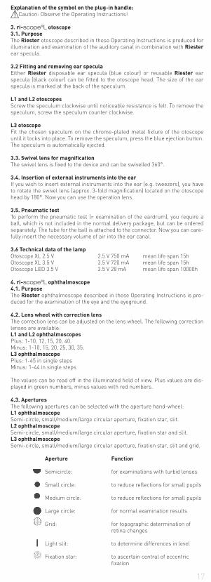
4.3. Apertures
The following apertures can be selected with the aperture hand-wheel:L1 ophthalmoscope
Semi-circle, small/medium/large circular aperture, fixation star, slit.L2 ophthalmoscope
Semi-circle, small/medium/large circular aperture, fixation star and slit.L3 ophthalmoscope
Semi-circle, small/medium/large circular aperture, fixation star, slit and grid.
Aperture Function
Semicircle: for examinations with turbid lenses Small circle: to reduce reflections for small pupils Medium circle: to reduce reflections for small pupils Large circle: for normal examination results Grid: for topographic determination of retina changes Light slit: to determine differences in level Fixation star: to ascertain central of eccentric fixation
18
4.4 Filters
Using the filter wheel, the following filters can be switched for each aperture:L1 ophthalmoscope Red-free filterL2 ophthalmoscope Red-free filter, blue filter and polarisation filter.L3 ophthalmoscope Red-free filter, blue filter and polarisation filter.
Filter Function
Red-free filter: contrast enhancing to assess fine vascular changes, e.g. retinal bleedingPolarisation filter: for precise assessment of tissue colours and to avoid retinal reflectionsBlue filter: for improved recognition of vascular abnormalities or bleeding, for fluorescence ophthalmology
For L2 + L3, every filter can be switched to every aperture.
4.5. Focussing device (only with L3)
Fast fine adjustment of the examination area to be observed is achieved from various distances by turning the focussing wheel.
4.6. Magnifying glass
A magnifying glass with 5-fold magnification is supplied with the ophthalmos-cope set. This can be positioned between the instrument head and the area under examination, as required. The area under examination is magnified ac-cordingly.
4.7. Technical data on the lamp
XL 2.5 V ophthalmoscope: 750 mA average service life 15 hXL 3.5 V ophthalmoscope: 690 mA average service life 15 hLED 3.5 V ophthalmoscope: 29 mA average service life 10000 h 5. Slit and spot retinoscopes
5.1 Purpose
The slit/spot retinoscopes (also known as skiascopes) described in these Ope-rating Instructions are produced to determine the refraction (ametropias) of the eye
5.2. Initial use and function
Position the required instrument head on point of attachment on top section of handle with both recesses of the instrument head bottom section being congru-ent with the two projecting guide cams of the battery handle. Press instrument head lightly on battery handle and rotate handle in clockwise direction to the stop. Remove head by rotating in counter-clockwise direction. Rotation and fo-cusing of the slit and/or spot image may now be effected by the knurled screw.
5.3. Rotation
The slit or spot image may be rotated by 360° by the control. Each angle may be directly read from the scale on the retinoscope.
5.4. Fixation cards
Fixation cards are suspended and fixed on the object side of the retinoscope into the bracket for the dynamic skiascope.
5.5 Technical data of the lamp
Slit retinoscope HL 2.5 V 2.5 V 440 mA mean life span 15hSlit retinoscope XL 3.5 V 3.5 V 690 mA mean life span 50hSpot retinoscope HL 2.5 V 2.5 V 450 mA mean life span 15hSpot retinoscope XL 3.5 V 3.5 V 640 mA mean life span 40h
6. Dermatoscope
6.1. Purpose
The ri-derma® dermascope described in these Operating Instructions is pro-duced for early identification of changes of skin pigmentation (malignant me-lanomas).
6.2. Initial use and function
Position the required instrument head on point of attachment on top section of handle with both recesses of the instrument head bottom section being congru-ent with the two projecting guide cams of the battery handle. Press instrument head lightly on battery handle and rotate handle in clockwise direction to the stop. Remove head by rotating in counter-clockwise direction.
6.3. Focusing
Focus the magnifying glass by rotating the eyepiece ring.
6.4. Skin adapters
Two skin adapters are supplied:
1) Including a scale of 0 - 10 mm for measuring melanotic skin changes, such as malign melanoma.
2) Without a scale Both skin adapters are suitable for multiple removal and replacement.
19
6.5 Technical data of the lamp
ri-derma® XL 2.5 V 2.5 V 750 mA mean life span 15hri-derma® XL 3.5 V 3.5 V 690 mA mean life span 15hri-derma® LED 3.5 V 3.5 V 28 mA mean life span 10000h
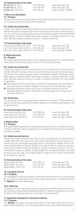
7. Bent-arm illuminator
7.1. Purpose
The bent-arm illuminator described in these Operating Instructions is produced for illuminating the oral cavity and the pharynx.
7.2. Initial use and function Position the required instrument head on point of attachment on top section of handle with both recesses of the instrument head bottom section being congru-ent with the two projecting guide cams of the battery handle. Press instrument head lightly on battery handle and rotate handle in clockwise direction to the stop. Remove head by rotating in counter-clockwise direction.
7.3 Technical data of the lamp
bent-arm illuminator XL 2.5 V 2.5 V 750 mA mean life span 15hbent-arm illuminator XL 3.5 V 3.5 V 690 mA mean life span 15hbent-arm illuminator LED 3.5 V 3.5 V 28 mA mean life span 10000h
8. Nasal speculum
8.1. Purpose
The nasal speculum described in these Operating Instructions is produced for illumination and therefore examination of the inside of the nose.
8.2. Initial use and function
Position the required instrument head on point of attachment on top section of handle with both recesses of the instrument head bottom section being congru-ent with the two projecting guide cams of the battery handle. Press instrument head lightly on battery handle and rotate handle in clockwise direction to the stop. Remove head by rotating in counter-clockwise direction. For two modes of operation:a) Fast expansion Push set screw on instrument head down with your thumb. This setting does not allow changes in the position of the speculum legs.b) Individual expansion Rotate set screw in clockwise direction until the required expansion width is obtained. Close legs again by turning screw in clockwise direction.
8.3. Swivel lens
The nasal speculum is equipped with a swivel lens of approx. 2.5X enlargement which may be simply pulled out and/or replaced in the opening provided on the nasal speculum.
8.4 Technical data of the lamp
nasal speculum XL 2.5 V 2.5 V 750 mA mean life span 15hnasal speculum XL 3.5 V 3.5 V 720 mA mean life span 15hnasal speculum LED 3.5 V 3.5 V 20 mA mean life span 10000h
9. Blade holder
9.1. Purpose
The blade holder described in these Operating Instructions is produced for exa-mination of the oral cavity and pharynx in combination with commercial woodenand plastic blades.
9.2. Initial use and function
Position the required instrument head on point of attachment on top section of handle with both recesses of the instrument head bottom section being con-gruent with the two projecting guide cams of the battery handle. Press inst-rument head lightly on battery handle and rotate handle in clockwise direction to the stop. Remove head by rotating in counter-clockwise direction. Insert a commercial wooden or plastic tongue blade into the aperture below the light opening up to the stop. The tongue blade is easy to remove after examination by actuating the ejector.
9.3 Technical data of the lamp
blade holder XL 2.5 V 2.5 V 750 mA mean life span 15hblade holder XL 3.5 V 3.5 V 720 mA mean life span 15hblade holder LED 3.5 V 3.5 V 20 mA mean life span 10000h
10. Laryngeal mirrors
10.1. Purpose
The laryngeal mirrors described in these Operating Instructions are produced for mirroring or examination of the oral cavity and pharynx in combination with the Riester bent-arm illuminator.
10.2. Initial use
Laryngeal mirrors may only be used in combination with the bent arm illumina-tor, thus ensuring maximum lighting conditions. Take two laryngeal mirrors and fix them in the required direction on the bent-arm illuminator.
11. Operation otoscope for veterinary medicine
11.1. Purpose
The Riester operation otoscope described in these Operating Instructions is produced exclusively for use on animals and for veterinary medicine and there-
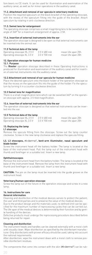
20
fore bears no CE mark. It can be used for illumination and examination of the auditory canal, as well as for minor operations in the auditory canal.
11.2. Attachment and removal of ear specula in veterinary medicine
Position the required speculum on the black bracket of the operating otoscope, with the recess of the speculum fitting into the guide of the bracket. Attach speculum by rotating in anti-clockwise direction.
11.3. Swivel lens for enlargement
The operating otoscope comprises a small magnifying lens to be swivelled at an angle of 360° for a maximum enlargement of approx. 2.5X.
11.4. Insertion of external instruments into the ear
The operation otoscope is designed to be open so that external instruments can be inserted into the animal ear.
11.5 Technical data of the lamp
Operating otoscope HL 2.5 V 2.5 V 680 mA mean life span 20hOperating otoscope XL 3.5 V 3.5 V 700 mA mean life span 20h
12. Operation otoscope for human medicine
12.1. Purpose
The Riester operation otoscope described in these Operating Instructions is produced for illumination and examination of the auditory canal and for inserti-on of external instruments into the auditory canal.
12.2 Attachment and removal of ear specula for human medicine
Place the desired speculum onto the black holder of the operation otoscope so that the recess on the speculum fits into the guide of the holder. Fix the specu-lum by turning it in a counter-clockwise direction.
12.3 Swivel lens for magnification
There is a small magnification lens which can be swivelled 360° on the operati-on otoscope with approx. 2.5-fold magnification.
12.4. Insertion of external instruments into the ear
The operation otoscope is designed so that external instruments can be inser-ted into the ear.
12.5 Technical data of the lamp
Operating otoscope HL 2.5 V 2.5 V 680 mA mean life span 20hOperating otoscope XL 3.5 V 3.5 V 700 mA mean life span 20h
13. Replacing the lamp
L1 otoscope
Remove the specula fitting from the otoscope. Screw out the lamp counter clockwise. Screw in the new lamp clockwise and replace the specula fitting.
L2, L3 otoscopes, ri-derma®, bent-arm illuminator, nasal speculum and
blade holder
Screw the instrument head off the battery holder. The lamp is located at the base of the instrument head. Pull the lamp out of the instrument head with thumb and forefinger or a suitable tool. Insert a new lamp.
Ophthalmoscopes
Remove the instrument head from the battery holder. The lamp is located at the base of the instrument head. Remove the lamp from the instrument head with thumb and forefinger or a suitable tool. Insert a new lamp.
CAUTION: The pin on the lamp must be inserted into the guide groove on the instrument head.
Veterinary/human operation otoscope
Screw the lamp out of the fixture in the operation otoscope and screw in a new lamp.
14. Instructions for care
General information
Cleaning and disinfection of the medical devices serves to protect the patient, the user and third parties and to preserve the value of the medical devices.Due to the product design and the materials used, no defined limit can be spe-cified for the maximum number of reprocessing cycles that can be carried out. The life span of the medical devices is determined by their function and by gent-le handling of the devices.Defective products must undergo the reprocessing procedure described before being returned for repair.
Cleaning and disinfection
The instrument heads and handles can be cleaned externally with a moist cloth until visually clean. Wipe-disinfection as specified by the disinfectant manufac-turer. Only disinfectants with proven efficacy should be used, taking into account the national requirements.After disinfection, wipe the instrument down with a moist cloth to remove pos-sible disinfectant residues.
The components that come into contact with the skin (ri-derma®) can be rub-
21
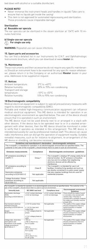
Guidelines and manufacturer's declaration - electromagnetic emissions The ri-scope® L is intended for operation in an electromagnetic environment as specified below. The customer or the user of the ri-scope® L should ensure that it is used in such an environment.
Emission measurements
Compliance
Electromagnetic environment - guidelines
HF emissions according to CISPR 11
Group 1
The ri-scope® L employs HF energy solely for an internal function. Its HF emission is therefore very low and it is unlikely that neighboring electronic devices will be affected by interference.
HF emissions according to CISPR 11
Class B
The ri-scope® L is intended for use in all facilities, including living quarters and such as are directly connected to a public power supply that also supplies buildings that are used for residential purposes.
Harmonics emissions according to EC61000-3-2
Not applicable
Voltage fluctuation / flicker emissions according to IEC61000-3-3
Not applicable
The ri-scope® L is intended for operation in an electromagnetic environment as specified below. The customer or the user of the ri-scope® L should ensure that it is used in such an environment.
Immunity tests IEC 60601 test level Compliance level Electromagnetic environment - guidelines
Electrostatic discharge (ESD) according to IEC61000-4-2
± 6 kV contact discharge ± 8 kV air discharge
± 6 kV contact discharge ± 8 kV air discharge
Floors should be made of wood or concrete or be covered with ceramic tiles. If the floor is covered with a synthetic material, the relative air humidity must be at least 30%.
Fast transient electrical interference/bursts according to IEC61000-4-4
± 2 kV for power lines ± 1 kV for input and output lines
Not applicable The quality of the supply voltage should correspond to that of a typical business or hospital environment.
Surges IEC61000-4-5
± 1 kV voltage phase-to-phase ± 2 kV voltage phase-to-earth
Not applicable The quality of the supply voltage should correspond to that of a typical business or hospital environment.
Voltage dips, short-time interruptions and fluctuations in the supply voltage according to IEC61000-4-11
<5% UT (>95 % drop in UT) for 0.5 cycles 40% UT (60 % drop in UT) for 5 cycles 70 % UT (30 % drop in UT) for 25 cycles
Not applicable
The quality of the supply voltage should correspond to that of a typical business or hospital environment
bed down with alcohol or a suitable disinfectant.
PLEASE NOTE!
• Never immerse the instrument heads and handles in liquids! Take care to ensure that no liquids get inside the casing!• This item is not approved for automated reprocessing and sterilization. These procedures cause irreparable damage!
Sterilization
a) Reusable ear specula
The ear specula can be sterilized in the steam sterilizer at 134°C with 10 mi-nutes hold time.
b) Single-use ear specula
For single use only
WARNING: Repeated use can cause infections.
15. Spare parts and accessories
You can find a detailed list in our Instruments for E.N.T. and Ophthalmologic Instruments brochure, which you can download at www.riester.de.
16. Maintenance
These instruments and their accessories do not require any specific maintenan-ce.Should an instrument have to be examined for any specific reason whatsoe-ver, please return it to the Company or an authorised Riester dealer in your area. Addresses to be supplied on request.
17. Notices
Ambient temperature: 0°C to +40°CRelative humidity: 30% to 70% non-condensingTransport and storage temperature: -10°C to +55°CRelative humidity: 10% to 95% non-condensing
18 Electromagnetic compatibility
Medical electrical equipment is subject to special precautionary measures with regard to electromagnetic compatibility (EMC).Portable and mobile high-frequency communication equipment can influence medical electrical equipment. This ME device is intended for operation in an electromagnetic environment as specified below. The user of the device should ensure that it is operated in such an environment.The ME device must not be used directly next to or arranged in a stack with other devices. If the device has to be operated near to or in a stacked arran-gement with other devices, then the ME device should be monitored in order to verify that it operates as intended in this arrangement. This ME device is intended exclusively for use by professional medical staff. This device can cause radio interference and can disrupt the operation of equipment nearby. Suitable remedial measures, such as for instance re-alignment, re-arrangement of the ME device or shielding, can become necessary.
22
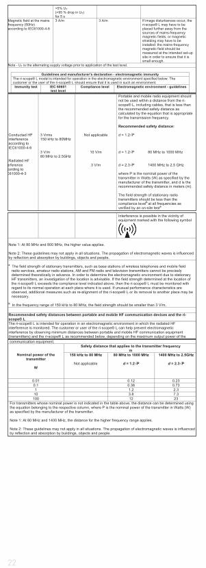
communication equipment.
Nominal power of the transmitter
W
Safety distance that applies to the transmitter frequency m
150 kHz to 80 MHz
Not applicable
80 MHz to 1000 MHz
d = 1.2 P
1400 MHz to 2.5GHz
d = 2.3 P
0.01 0.12 0.23 0.1 0.38 0.73 1 1.2 2.3
10 3.8 7.3 100 12 23
For transmitters whose nominal power is not indicated in the table above, the distance can be determined using the equation belonging to the respective column, where P is the nominal power of the transmitter in Watts (W) as specified by the manufacturer of the transmitter. Note 1: At 80 MHz and 1400 MHz, the distance for the higher frequency range applies. Note 2: These guidelines may not apply in all situations. The propagation of electromagnetic waves is influenced by reflection and absorption by buildings, objects and people.
Interference is possible in the vicinity of equipment marked with the following symbol
Note 1: At 80 MHz and 800 MHz, the higher value applies. Note 2: These guidelines may not apply in all situations. The propagation of electromagnetic waves is influenced by reflection and absorption by buildings, objects and people. a The field strength of stationary transmitters, such as base stations of wireless telephones and mobile field
radio services, amateur radio stations, AM and FM radio and television transmitters cannot be precisely determined theoretically in advance. In order to determine the electromagnetic environment due to stationary HF transmitters, an investigation of the location is advisable. If the field strength determined at the location of the ri-scope® L exceeds the compliance level indicated above, then the ri-scope® L must be monitored with regard to its normal operation at each place where it is used. If unusual performance characteristics are observed, additional measures such as re-alignment of the ri-scope® L or its removal to another place may be necessary.
b In the frequency range of 150 kHz to 80 MHz, the field strength should be smaller than 3 V/m.
Recommended safety distances between portable and mobile HF communication devices and the ri-scope® L The ri-scope® L is intended for operation in an electromagnetic environment in which the radiated HF interference is monitored. The customer or user of the ri-scope® L can help prevent electromagnetic interference by observing minimum distances between portable and mobile HF communication equipment (transmitters) and the ri-scope® L as recommended below, depending on the maximum output power of the
<5% UT (>95 % drop in UT) for 5 s
Magnetic field at the mains frequency (50Hz) according to IEC61000-4-8
3 A/m 3 A/m If image disturbances occur, the ri-scope® L may have to be placed further away from the sources of mains-frequency magnetic fields, or magnetic shielding may have to be installed: the mains-frequency magnetic field should be measured at the intended set-up site in order to ensure that it is small enough.
Note - UT is the alternating supply voltage prior to application of the test level.
Guidelines and manufacturer's declaration - electromagnetic immunity The ri-scope® L model is intended for operation in the electromagnetic environment specified below. The customer or the user of the ri-scope® L should ensure that it is used in such an environment. Immunity test IEC 60601
test level Compliance level Electromagnetic environment - guidelines
Conducted HF interference according to IEC61000-4-6 Radiated HF
erference cording to C61000-4-3
3 Vrms 150 kHz to 80MHz 3 V/m 80 MHz to 2.5GHz
Not applicable
10 V/m
3 V/m
Portable and mobile radio equipment should not be used within a distance from the ri-scope® L, including cables, that is less than the recommended safety distance as calculated by the equation that is appropriate for the transmission frequency. Recommended safety distance: d = 1.2 P d = 1.2 P 80 MHz to 1000 MHz d = 2.3 P 1400 MHz to 2.5 GHz where P is the nominal power of the transmitter in Watts (W) as specified by the manufacturer of the transmitter, and d is the recommended safety distance in meters (m). The field strength of stationary radio transmitters should be less than the compliance levelb at all frequencies as verified by an on-site testa

23
FRENCH
1. Informations importantes, à lire attentivement avant la mise en service
Vous avez entre les mains un dispositif de diagnostic Riester de grande valeur, qui a été fabriqué conformément à la directive européenne 93/42/CE « Dispo-sitifs médicaux » et fait l’objet de contrôles de qualité permanents des plus rigoureux. La qualité incomparable de ce dispositif est le garant de la fiabilité de vos diagnostics. L’utilisation des manches à piles Riester des têtes d’inst-rument ri-scope® et ri-derma® et de leurs accessoires est décrite dans ce mode d’emploi. Veuillez s’il vous plaît le lire attentivement avant d’utiliser votre dispositif pour la première fois et conservez-le soigneusement. Si vous avez des questions, nous, ou le représentant des produits Riester compétent pour votre secteur, nous tenons à votre entière disposition pour y répondre. Vous trouverez notre adresse à la dernière page de ce mode d’emploi. L’adresse de notre représentant vous sera volontiers communiquée sur demande. Veuillez s’il vous plaît noter que tous les instruments décrits dans ce mode d’emploi ne doivent être utilisés que par des personnes spécialement formées à cet ef-fet. L’otoscope chirurgical du set Vet-I est un instrument produit exclusivement pour la médecine vétérinaire. Il ne porte donc pas le marquage CE. Veuillez également noter que le bon fonctionnement et la sécurité de nos instruments ne sont garantis que si vous utilisez exclusivement les instruments et leurs accessoires de Riester.
Consignes de sécurité :
Attention : Se conformer au mode d’emploi ! Double mise à la terre de l’appareil
Classification
Applicateur de type B tête d‘otoscope avec spéculum
2. Manches à piles et mise en service
2.1. Destination
Les manches à piles Riester décrits dans ce mode d’emploi sont destinés à alimenter les têtes des instruments en énergie (les lampes sont intégrées aux têtes des instruments). Ils servent en outre de supports.
2.2. Gamme de manches à pile
Toutes les têtes d’instrument décrites dans ce mode d’emploi s’adaptent sur les manches à piles suivants et peuvent donc être combinées individuellement. Elles s’adaptent également sur les manches de la station de diagnostic murale ri-former®.ATTENTION : Les têtes d’instrument à LED ne sont compatibles qu’à partir d’un numéro de série déterminé de la station de diagnostic ri-former®. Nous vous fournirons sur demande des indications sur la compatibilité de votre station de diagnostic.
Pour otoscopes ri-scope®L, ophtalmoscopes ri-scope®L, perfect, O.R.L.,
praktikant, de luxe®, Vet, rétinoscopes à trait et à spot, ri-vision®
a) Manche à piles de type C avec rheotronic® 2,5 V. Ces manches fonctionnent avec 2 piles alcalines de type C Baby du commerce (référence CEI LR14) ou un ri-accu® de 2,5 V. Le manche avec le ri-accu® de Riester ne peut être chargé que dans la station de chargement ri-charger® de Riester.
b) Manche à piles de type C avec rheotronic® 3,5 V. Ces manches fonctionnent avec 2 piles au lithium de type CR 123A du commerce (Attention: unique- ment avec douille réductrice + régleur LDO) ou un ri-accu®L de 3,5 V. Le manche avec le ri-accu®L de Riester ne peut être chargé que dans la sta- tion de chargement ri-charger®L de Riester.
c) Manche à piles rechargeables de type C, 2,5 V ou 3,5 V, avec rheotronic® pour chargement dans la prise de courant de 230 V ou 120 V. Le manche est livrable en 2,5 V ou 3,5 V et peut être commandé pour tension secteur 230 V ou 120 V. Veuillez s’il vous plaît noter que le manche ne peut être utilisé qu’avec le ri-accu® ou le ri-accu®L de Riester.
d) Manche à piles de type AA avec rheotronic® 2,5 V. Ces manches foncti- onnent avec 2 piles alcalines de type AA Baby du commerce (référence CEI LR6) ou un ri-accu® de 2,5 V. Le manche avec le ri-accu®L de Riester ne peut être chargé que dans la station de chargement ri-charger® de Riester.
e) Manche à piles de type AA avec rheotronic® 3,5 V. Ces manches foncti- onnent avec 2 piles au lithium de type CR 123A du commerce (Attention: uniquement avec un régleur LDO) ou un ri-accu®L de 3,5 V. Le manche avec le ri-accu®L de Riester ne peut être chargé que dans la station de charge- ment ri-charger®L de Riester.
2.3. Insertion et extraction des piles et des accus
Types de manches (2.2. a, b, d et e) Dévisser le capuchon dans le bas du man-che. Insérer dans le fourreau les piles ou l’accu correspondant au manche et à la tension (voir 2.2) de manière que les pôles plus (+) soient dirigés vers la partie supérieure du manche. Sur l’accu, il y a à côté du signe (+) une flèche indiquant dans quelle direction le pôle doit être orienté. Bien revisser le capuchon sur le manche.
24
ATTENTION : Pour les piles lithium (uniquement pour les poignées de batterie de type C), vous avez besoin d‘une douille réductrice (n° réf. : 12652) + régleur LDO (n° réf. : 12653).
Poignée C
En cas d‘équipement ultérieur :
Dévisser le couvercle de poignée sur la partie inférieure de la poignée. Avec les piles lithium, la douille réductrice est d‘abord insérée par l‘extrémité dans la douille de poignée au niveau de la bague-ressort, le régleur LDO doit être inséré dans le sens de la flèche. Les piles lithium doivent être insérées de manière à ce que leur borne positive soit dirigée vers la partie supérieure de la poignée. Visser fermement le couvercle de poignée sur la poignée.
Poignée AA
En cas d‘équipement ultérieur :
Dévisser le couvercle de poignée sur la partie inférieure de la poignée. Avec les piles lithium, le régleur LDO doit être inséré dans le sens de la flèche. Les piles lithium doivent être insérées de manière à ce que leur borne positive soit dirigée vers la partie supérieure de la poignée. Visser fermement le couvercle de poignée sur la poignée.Pour extraire les piles du manche, dévisser le capuchon et secouer légèrement le manche.
Avant d’utiliser le manche pour la première fois, vous devez charger les accus (dans le manche à piles de Riester) dans la station de chargement ri-charger® de Riester. Un mode d’emploi, à respecter impérativement, est joint à chaque station de chargement.
Types de manches (2.2. c)
Avant d’utiliser le manche à prise pour la première fois, le charger en le bran-chant dans la prise de courant pour 24 heures au maximum.ATTENTION : La durée de chargement du manche à prise (uniquement avec accus NiMH) ne doit pas dépasser 24 heures. Dévisser le capuchon dans le bas du manche. Insérer dans le fourreau l’accu correspondant au manche et à la tension (voir 2.2). Pour les accus de 2,5 V, veiller à ce que le pôle plus (+) de l’accu soit dirigé vers la partie supérieure du manche ; à côté du signe (+), une flèche indique le sens d’insertion de l’accu dans le manche. Pour les accus de 3,5 V, le sens importe peu. Bien revisser le capuchon sur le manche. Tourner la partie inférieure du manche dans le sens antihoraire. Les contacts de la prise de courant apparaissent. Les contacts ronds sont pour le fonctionnement sur secteur 230 V, les contacts plats sont pour le fonctionnement sur secteur 120 V. Introduire le manche par la partie inférieure dans la prise de courant pour le charger.
ATTENTION: Pour remplacer les accus, toujours débrancher de manche de la prise de courant. Pour remplacer le ri-accu®, dévisser le capuchon dans le bas du manche en le tournant dans le sens antihoraire. Sortir le ri-accu® du manche en secouant ce dernier légèrement vers le bas. Introduire le ri-accu® dans le manche. Pour les accus de 2,5 V, veiller à ce que le pôle (+) de l’accu soit dirigé vers la partie supérieure du manche ; à côté du signe (+), un flèche indique le sens d’insertion de l’accu dans le manche. Pour les accus de 3,5 V, le sens importe peu. Bien revisser le capuchon sur le manche en le tournant dans le sens horaire.Caractéristiques techniques : Au choix, 230 V ou 120 V
ATTENTION :
• Si vous n’utilisez pas l’appareil pendant une durée prolongée ou si vous l’emmenez en voyge, sortez s’il vous plaît les piles et les accus du manche.• Ne remplacer les piles que si l’intensité lumineuse de l’instrument faiblit.• Pour obtenir un rendement lumineux optimal, il est recommandé de toujours remplacer les piles usagées par des piles neuves de qualité (voir 2.2).• Si vous pensez que du liquide ou de l’humidité ont pu pénétrer dans le manche, ne charger ce dernier en aucun cas. Cela risque de provoquer une décharge électrique qui peut être mortelle, en particulier avec les manches à prise.• Pour allonger la durée de vie du ri-accu®, ne recharger ce dernier que lorsque l’intensité lumineuse de l’instrument faiblit.
Élimination :
Les piles et les accus doivent être éliminés comme déchets spéciaux. Pour tou-te information à ce sujet, veuillez s’il vous plaît vous adresser à votre commune ou au délégué à l’environnement compétent.
2.4. Mise en place des têtes d’instrument
Poser la tête d’instrument souhaitée sur le logement dans la partie supérieure du manche de manière que les deux encoches de la partie inférieure de la tête se trouvent sur les deux ergots de guidage du manche. Appuyer légèrement sur la tête et tourner le manche à fond dans le sens horaire. Pour détacher la tête, tourner le manche dans le sens antihoraire.
2.5. Mise en marche et arrêt
Manches à piles de type C et AA Allumez l’instrument en touchant sur la bague de réglage en haut du manche en direction sens horaire.Pour arréter l’inst-rument poussez la bague en sens antihoraire jusqu’à l’instrument est arrété
25
2.6. rheotronic® pour le réglage de l’intensité de la lumière
Grâce à la technique rheotronic il est possible de régler l’intensité de la lumière pour les manches type C et AA. L’intensité de la lumière dépend combien de fois vous tournez la bague de réglage en sens horaire ou antihoraire.
ATTENTION : A chaque enclenchement du manche l’intensité de lumière est à 100%. Extinction de sécurité automatique après 180 secondes.
Signification du symbole sur la manche à prise: ATTENTION : Se conformer au mode d’emploi !
3. Otoscope ri-scope®L3.1. Destination
L’otoscope Riester décrit dans ce mode d’emploi sert à éclairer le conduit audi-tif et à l’examiner avec les spéculums auriculaires Riester.
3.2. Insertion et éjection des spéculums auriculaires
On peut adapter sur la tête de l’otoscope, au choix, des spéculums auriculai-res jetables de Riester (de couleur bleue) ou des spéculums réutilisables de Riester ! (de couleur noire). La taille du spéculum auriculaire est indiquée à l’arrière du spéculum.
Otoscope L1 et L2
Tourner le spéculum dans le sens horaire jusqu‘à ce que vous sentiez une ré-sistance. Pour éjecter le spéculum, le tourner dans le sens antihoraire.Otoscope L3
Mettre le spéculum sur la monture métallique chromée de l’otoscope et ap-puyer jusqu’à vous sentiez qu’il s’encliquète. Pour éjecter le spéculum, appuyer sur le bouton bleu. Le spéculum est éjecté automatiquement.
3.3. Lentille grossissante pivotante
La lentille pivotante est fixée sur l’instrument et peut être tournée de 360°.
3.4. Introduction d’instruments externes dans l’oreille
Si vous voulez introduire dans l’oreille des instruments externes (p. ex. une pin-cette), vous devez faire pivoter de 180° la lentille grossissante (grossissement env. x 3) qui se trouve sur la tête de l’otoscope. Ensuite, vous pouvez mettre en place la lentille chirurgicale.
3.5. Otoscopie pneumatique
Pour pouvoir effectuer l’otoscopie pneumatique (= un examen du tympan), vous avez besoin d’une poire, qui n’est pas comprise dans la livraison standard, mais que vous pouvez commander à part. Le tuyau de la poire est enfoncé sur le rac-cord. Vous pouvez maintenant insuffler doucement la quantité d’air nécessaire dans le canal de l’oreille.
3.6 Caractéristiques techniques de la lampe
Otoscope XL 2,5 V 2,5 V 750 mA durée de vie moy. 15 hOtoscope XL 3,5 V 3,5 V 720 mA durée de vie moy. 15 hOtoscope à LED 3,5 V 3,5 V 28 mA durée de vie moy. 10 000 h
4. Ophtalmoscope ri-scope®L4.1. Destination
L’ophtalmoscope Riester décrit dans ce mode d’emploi sert pour l’examen de l’oeil et du fond de l’oeil.
4.2. Roue à lentilles avec lentilles de correction
Les lentilles de correction peuvent être réglées sur la roue à lentilles. Vous avez le choix entre les lentilles de correction suivantes :
Ophtalmoscope L1 et L2
Plus : 1-10, 12, 15, 20, 40.Moins : 1-10, 15, 20, 25, 30, 35.
Ophtalmoscope L3
Plus : 1-45 par pasMoins : 1-44 par pas
Lecture des valeurs dans l’afficheur à éclairage. Affichage des valeurs positives en vert et des valeurs négatives en rouge.
4.3. Diaphragmes
La roue à diaphragmes permet de sélectionner les diaphragmes suivants:
Ophthalmoscope L1:
Demi-lune, petit/moyen/grand spot, étoile de fixation, fente.
Ophthalmoscope L2:
Demi-lune, petit/moyen/grand spot, étoile de fixation, fente.
Ophthalmoscope L3:
Demi-lune, petit/moyen/grand spot, étoile de fixation, fente et grille.“
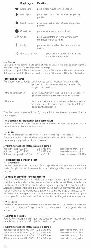
26
Diaphragme Fonction
Demi-lune: pour examen avec lentille opaque
Petit spot: pour la réduction des réflexes des petites pupilles
Sport moyen: pour la réduction des réflexes des petites pupilles
Grand spot: pour les examens de fond d‘oeil
Grille: pour la constatation topographique des modifications de la rétine
Fente: pour la détermination des différences de niveau
Étoile de fixation: pour la constatation des fixations centrale et excentrée
4.4. Filtres
La roue à filtres permet d’utiliser les filtres suivants avec chaque diaphragme :Ophtalmoscope L1 Filtre absorbant du rougeOphtalmoscope L2 Filtre absorbant du rouge, filtre bleu et filtre de polarisation.Ophtalmoscope L3 Filtre absorbant du rouge, filtre bleu et filtre de polarisation.
Fonction des filtres
Filtre absorbant du rouge : accentue les contrastes pour l’évaluation des petites modifications vasculaires, par exemple, saignements rétiniens
Filtre de polarisation : pour l’évaluation chromatique exacte des tissus et pour une réduction des réflexions de la cornée
Filtre bleu : pour une meilleure reconnaissance des anomalies vasculaires ou des saignements, pour l’ophtalmos- copie par fluorescence
Pour les ophtalmoscopes L2 + L3, chaque filtre peut être utilisé avec chaque diaphragme.
4.5. Dispositif de focalisation (uniquement L3)
La roue de focalisation permet de régler rapidement et avec précision le champ à examiner sur différentes distances.
4.6. Loupe
Une loupe grossissant au facteur 5 est livrée avec l’ophtalmoscope.Elle peut être intercalée si nécessaire entre la tête de l’instrument et le champ d’examen pour grossir le champ d’examen.
4.7 Caractéristiques techniques de la lampe
Ophtalmoscope XL 2,5 V 2,5 V 750 mA durée de vie moy. 15 hOphtalmoscope XL 3,5 V 3,5 V 690 mA durée de vie moy. 15 hOphtalmoscope à LED 3,5 V 3,5 V 29 mA durée de vie moy. 10 000 h
5. Rétinoscopes à trait et à spot
5.1. Destination
Les rétinoscopes à trait et à spot (aussi appelés skiascopes) décrits dans ce mode d’emploi servent à mesurer le pouvoir réfringent (anomalies de la vision) de l’oeil.
5.2. Mise en service et fonctionnement
Placez la tête d‘instrument choisie sur le logement de la partie supérieure du manche de telle sorte que les deux évidements de la partie inférieure de la tête d‘instrument soient placés sur les deux ergots de guidage du manche à piles. Appuyez légèrement la tête d‘instrument sur le manche et imprimez une rota-tion au manche dans le sens des aiguilles d‘une montre jusqu‘à la butée. Le re-trait de la tête se fait par rotation dans le sens inverse. La vis moletée vous per-met de procéder à la rotation et à la focalisation de l‘image à traits ou à points.
5.3. Rotation
L‘élément de commande permet de faire tourner de 360° l‘image à traits ou à points. La valeur de l‘angle peut être lue directement sur la graduation du rétinoscope.
5.4 Carte de Fixation
Pour la Rétinoscopie dynamique, les cartes de fixation sont montées et fixées dans le support sur le coté objet de la retinoscope.
5.5 Caractéristiques techniques de la lampe
Rétinoscope en fente HL 2,5 V 2,5 V 440 mA durée de vie moy. 15 hRétinoscope en fente XL 3,5 V 3,5 V 690 mA durée de vie moy. 50 hRétinoscope en rond HL 2,5 V 2,5 V 450 mA durée de vie moy. 15 hRétinoscope en rond XL 3,5 V 3,5 V 640 mA durée de vie moy. 40 h
27
6. Dermatoscope
6.1. Destination
Le dermatoscope ri-derma® décrit dans ce mode d’emploi sert au dépistage précoce des modifications de la pigmentation cutanée (mélanomes malins).
6.2. Mise en service et fonctionnement
Placez la tête d‘instrument choisie sur le logement de la partie supérieure du manche de telle sorte que les deux évidements de la partie inférieure de la tête d‘instrumentsoient placés sur les deux ergots de guidage du manche à piles. Appuyez légèrement la tête d‘instrument sur le manche et imprimez une rotation au manche dans le sens des aiguilles d‘une montre jusqu‘à la butée. Le retrait de la tête se fait par rotation dans le sens inverse.
6.3. Focalisation
Ajustez la focale de la loupe en faisant tourner l‘anneau de l‘oculaire.
6.4. Embouts pour la peau
2 embouts pour la peau sont fournis:1) avec une graduation de 0 à 10 mm pour mesurer les modifications pigmentées de la peau telles que les mélanomes malins.2) sans graduation. Les deux embouts pour la peau s‘enlèvent et se remplacent facilement.
6.5 Caractéristiques techniques de la lampe
ri-derma® XL 2,5 V 2,5 V 750 mA durée de vie moy. 15 hri-derma® XL 3,5 V 3,5 V 690 mA durée de vie moy. 15 hri-derma® à LED 3,5 V 3,5 V 28 mA durée de vie moy. 10 000 h
7. Support de lampe
7.1. Destination
Le support de lampe décrit dans ce mode d’emploi sert à éclairer la cavité buccale et la gorge.
7.2. Mise en service et fonctionnement
Placez la tête d‘instrument choisie sur le logement de la partie supérieure du manche de telle sorte que les deux évidements de la partie inférieure de la tête d‘instrument soient placés sur les deux ergots de guidage du manche à piles. Appuyez légèrement la tête d‘instrument sur le manche et imprimez une rotation au manche dans le sens des aiguilles d‘une montre jusqu‘à la butée. Le retrait de la tête se fait par rotation dans le sens inverse.
7.3 Caractéristiques techniques de la lampe
support de lampe XL 2,5 V 2,5 V 750 mA durée de vie moy. 15 hsupport de lampe XL 3,5 V 3,5 V 690 mA durée de vie moy. 15 hsupport de lampe à LED 3,5 V 3,5 V 28 mA durée de vie moy. 10 000 h
8. Spéculum nasal
8.1. Destination
Le spéculum nasal décrit dans ce mode d’emploi sert à éclairer et examiner l’intérieur du nez.
8.2. Mise en service et fonctionnement
Placez la tête d‘instrument choisie sur le logement de la partie supérieure du manche de telle sorte que les deux évidements de la partie inférieure de la tête d‘instrument soient placés sur les deux ergots de guidage du manche à piles. Appuyez légèrement la tête d‘instrument sur le manche et imprimez une rotation au manche dans le sens des aiguilles d‘une montre jusqu‘à la butée. Le retrait de la tête se fait par rotation dans le sens inverse.
Deux modes de manipulation sont possibles:a) Écartement rapide Enfoncez avec le pouce la vis de réglage de la tête d‘instrument vers le bas. Avec ce réglage, la position des branches du spéculum ne peut plus être modifiée.b) Écartement progressif Faites tourner la vis de réglage dans le sens des aiguilles d‘une montre jusqu‘à ce que vous ayez atteint l‘écartement voulu. Les branches se referment lorsque vous tournez la vis dans l‘autre sens.
8.3. Lentille pivotante
Le spéculum nasal porte une lentille pivotante avec un grossissement d‘env. 2,5 fois, qui peut être tout simplement retirée ou replacée dans l‘ouverture du spéculum prévue à cet effet, selon les besoins.
8.4 Caractéristiques techniques de la lampe
Spéculum nasal XL 2,5 V 2,5 V 750 mA durée de vie moy. 15 hSpéculum nasal XL 3,5 V 3,5 V 720 mA durée de vie moy. 15 hSpéculum nasal à LED 3,5 V 3,5 V 28 mA durée de vie moy. 10 000 h
9. Support pour abaisse-langue
9.1. Destination
Le support pour abaisse-langue décrit dans ce mode d’emploi sert pour l’ex-amen de la cavité buccale et de la gorge avec les abaisse-langue en bois et en plastique du commerce.
9.2. Mise en service et fonctionnement
Placez la tête d‘instrument choisie sur le logement de la partie supérieure du
28
manche de telle sorte que les deux évidements de la partie inférieure de la tête d‘instrument soient placés sur les deux ergots de guidage du manche à piles. Appuyez légèrement la tête d‘instrument sur le manche et imprimez une rotation au manche dans le sens des aiguilles d‘une montre jusqu‘à la butée. Le retrait de la tête se fait par rotation dans le sens inverse. Introduisez un abaisse-langue courant du commerce en bois ou en plastique dans l‘ouverture située au-dessous de la sortie de lumière jusqu‘à la butée. Après l‘examen, l’abaisse-langue est facile à retirer par actionnement de l‘éjecteur.
9.3 Caractéristiques techniques de la lampe
support pour abaisse-langue XL 2,5 V 2,5 V 750 mA durée de vie moy. 15 hsupport pour abaisse-langue XL 3,5 V 3,5 V 720 mA durée de vie moy. 15 hsupport pour abaisse-langue à LED 3,5 V 3,5 V 20 mA durée de vie moy. 10 000 h
10. Miroir pour larynx
10.1. Destination
Les miroirs pour larynx décrits dans ce mode d’emploi servent à visualiser et examiner la cavité buccale et la gorge ; ils s’utilisent avec le support de lampe Riester.
10.2. Mise en service
Le miroir de laryngologie peut uniquement être utilisé en association avec le porte-lampe. Un éclairage optimal est ainsi garanti. Prendre l’un des deux mi-roirs pour larynx et le mettre à l’avant sur le support de lampe dans la direction souhaitée.
11. Otoscope chirurgical pour la médecine vétérinaire
11.1. Destination
L’otoscope chirurgical pour la médecine vétérinaire Riester décrit dans ce mode d’emploi est destiné à être utilisé uniquement en médecine vétérinaire, sur les animaux. Il ne porte donc pas le marquage CE. Il peut être utilisé pour éclairer et examiner le conduit auditif ainsi que pour les petites interventions chirurgicales dans le conduit auditif.
11.2. Mise en place et retrait des spéculums auriculaires de médecine vétéri-
naire
Placez le spéculum choisi sur la fixation noire de l‘otoscope d‘opération de ma-nière à ce que l‘évidement du spéculum s‘adapte dans le guidage de la fixation. Fixez le spéculum en le faisant tourner dans le sens inverse des aiguilles d‘une montre.
11.3. Lentille pivotante de grossissement
L‘otoscope d‘opération possède une petite lentille pivotante à 360° qui assure un grossissement d‘env. 2,5 fois.
11.4. Introduction d’instruments externes dans l’oreille
L’otoscope chirurgical a une conception ouverte, de manière à permettre d’in-troduire des instruments externes dans l’oreille de l’animal.
11.5 Caractéristiques techniques de la lampe
Otoscope opératoire HL 2,5 V 2,5 V 680 mA durée de vie moy. 20 hOtoscope opératoire XL 3,5 V 3,5 V 700 mA durée de vie moy. 20 h
12. Otoscope chirurgical pour la médecine humaine
12.1. Destination
L’otoscope chirurgical Riester décrit dans ce mode d’emploi est destiné à éc-lairer et examiner le conduit auditif et à introduire des instruments externes dans le conduit auditif.
12.2. Mise en place et retrait des spéculums auriculaires en médecine hu-
maine
Placez le spéculum auriculaire adéquat sur le support noir de l‘otoscope chi-rurgical de façon à ce que le creux du spéculum se place dans la glissière du support. Fixez le spéculum en le faisant tourner dans le sens inverse de celui des aiguilles d‘une montre.
12.3. Lentille pivotante grossissante
Une petite lentille grossissante pivotant sur 360° et dont le facteur de grossisse-ment est d‘environ 2,5 est montée sur l‘otoscope chirurgical.
12.4. Introduction d’instruments externes dans l’oreille
L’otoscope chirurgical est conçu de manière que des instruments externes pu-issent être introduits dans l’oreille.
12.5 Caractéristiques techniques de la lampe
Otoscope opératoire HL 2,5 V 2,5 V 680 mA durée de vie moy. 20 hOtoscope opératoire XL 3,5 V 3,5 V 700 mA durée de vie moy. 20 h
13. Remplacement de la lampe
Otoscope L1
Détacher le porte-spéculum de l’otoscope. Tourner la lampe dans le sens an-tihoraire pour la démonter. Mettre la lampe neuve en place en la tournant à fond dans le sens horaire et remettre le porte-spéculum en place.
Otoscopes L2, L3,
ri-derma®, support de lampe, spéculum nasal et support d’abaisse-langue

29
Détacher la tête de l’instrument du manche à piles. La lampe se trouve dans le bas de la tête de l’instrument. Sortir la lampe de la tête de l’instrument en la tenant par le pouce et l’index ou en vous aidant d’un outil adapté. Introduire la lampe neuve dans la tête et bien la serrer.
Ophtalmoscopes
Détacher la tête de l’instrument du manche à piles. La lampe se trouve dans le bas de la tête de l’instrument. Sortir la lampe de la tête de l’instrument en la tenant par le pouce et l’index ou au moyen d’un outil adapté. Introduire la lampe neuve dans la tête et bien la serrer.ATTENTION : La pointe de la lampe doit être enfoncée dans l’encoche dans la tête de l’instrument.
Otoscopes chirurgicaux pour la médecine vétérinaire/ humaine
Extraire la lampe de la douille dans l’otoscope chirurgical, mettre en place une lampe neuve et la serrer à fond.
14. Instructions d‘entretien
Remarque générale
Le nettoyage et la désinfection des produits médicaux servent à la protection des patients, des utilisateurs et des tiers, ainsi qu’à la conservation des produits médicaux.En raison du concept du produit et des matériaux utilisés, il n’est pas possible de définir précisément un nombre maximal de cycles de nettoyage pouvant être exécutés. La durée de vie des produits médicaux dépend de leur bon foncti-onnement et de leur manipulation correcte.Les produits défectueux doivent être nettoyés conformément à la procédure décrite avant d’être envoyés pour réparation.
Nettoyage et désinfection
Les faces externes des têtes d‘instruments et des poignées peuvent être es-suyées avec un chiffon humide jusqu‘à ce qu‘elles soient visiblement propres.Désinfection par essuyage selon les prescriptions du fabricant du désinfectant. Utiliser uniquement des produits dont l’efficacité est prouvée en tenant compte des réglementations nationales.Après la désinfection, essuyer l’instrument avec un chiffon humide pour élimi-ner les éventuels résidus de désinfectant.
Essuyer les embouts cutanés (ri-derma®) avec un chiffon imbibé d‘alcool ou de désinfectant compatible.
ATTENTION !
• Ne jamais immerger les têtes d‘instruments et les poignées dans des liquides ! Veiller à éviter toute infiltration de liquide dans le boîtier !• Cet article n‘est pas compatible au nettoyage et à la stérilisation en automate. Ceci entraîne des dommages irréparables !
Stérilisation
a) Spéculum auriculaire réutilisable Les spéculums auriculaires peuvent être stérilisés en autoclave à 134 °C et durée plateau de 10 minutes.b) Spéculum auriculaire à usage unique Uniquement pour usage unique ATTENTION : toute réutilisation peut entraîner une infection.
15. Pièces de rechange et accessoires
Vous trouverez une liste détaillée dans notre brochure téléchargeable Instru-ments pour O.R.L. Instruments ophtalmologiques que vous trouverez sur le site www.riester.de.
16. Entretien
Les instruments et leurs accessoires n’exigent pas d’entretien particulier. Si, pour une raison quelconque, un instrument devait être contrôlé, veuillez nous l’adresser ou l’envoyer à un commerçant Riester agréé proche de chez vous, que nous serons heureux de vous indiquer.
17. Informations utiles
Température ambiante : 0 ° à +40 °Humidité relative de l‘air : 30 % à 70 % non condensanteTempérature de transport et de stockage : -10 ° à +55 °Humidité relative de l‘air : 10 % à 95 % non condensante
18 Compatibilité électromagnétique
Les appareils électriques médicaux doivent faire l‘objet de mesures de précauti-on spéciales concernant la compatibilité électromagnétique (CEM).Les dispositifs de communication haute fréquence portables et mobiles peuvent perturber les appareils électriques médicaux. Cet appareil électrique médical est conçu pour fonctionner dans un environnement électromagnétique confor-me aux points ci-dessous. L‘utilisateur doit s‘assurer que l‘appareil est utilisé dans un tel environnement.L‘appareil électrique médical ne doit pas être utilisé s‘il est installé directement à côté d‘autres appareils ou empilé sur ceux-ci. Si l‘appareil électrique médical doit fonctionner directement à côté d‘autres appareils ou empilé sur ceux-ci, il convient de l‘observer afin de vérifier son fonctionnement correct dans cette 1.
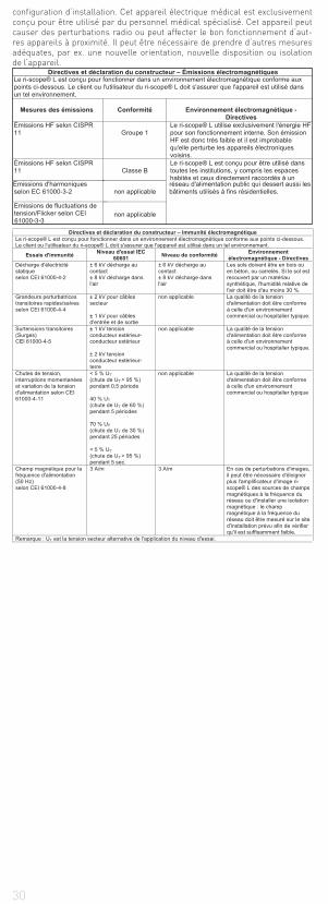
30
configuration d‘installation. Cet appareil électrique médical est exclusivement conçu pour être utilisé par du personnel médical spécialisé. Cet appareil peut causer des perturbations radio ou peut affecter le bon fonctionnement d‘aut-res appareils à proximité. Il peut être nécessaire de prendre d‘autres mesures adéquates, par ex. une nouvelle orientation, nouvelle disposition ou isolation de l‘appareil.
Directives et déclaration du constructeur – Émissions électromagnétiques Le ri-scope® L est conçu pour fonctionner dans un environnement électromagnétique conforme aux points ci-dessous. Le client ou l'utilisateur du ri-scope® L doit s'assurer que l'appareil est utilisé dans un tel environnement.
Mesures des émissions
Conformité
Environnement électromagnétique -
Directives Émissions HF selon CISPR 11
Groupe 1
Le ri-scope® L utilise exclusivement l'énergie HF pour son fonctionnement interne. Son émission HF est donc très faible et il est improbable qu'elle perturbe les appareils électroniques voisins.
Émissions HF selon CISPR 11
Classe B
Le ri-scope® L est conçu pour être utilisé dans toutes les institutions, y compris les espaces habités et ceux directement raccordés à un
Émissions d'harmoniques selon EC 61000-3-2
non applicable
réseau d'alimentation public qui dessert aussi les bâtiments utilisés à fins résidentielles.
Émissions de fluctuations de tension/Flicker selon CEI 61000-3-3
non applicable
Directives et déclaration du constructeur – Immunité électromagnétique Le ri-scope® L est conçu pour fonctionner dans un environnement électromagnétique conforme aux points ci-dessous. Le client ou l'utilisateur du ri-scope® L doit s'assurer que l'appareil est utilisé dans un tel environnement.
Essais d'immunité Niveau d'essai IEC 60601 Niveau de conformité Environnement
électromagnétique - Directives Décharge d'électricité statique selon CEI 61000-4-2
± 6 kV décharge au contact ± 8 kV décharge dans l'air
± 6 kV décharge au contact ± 8 kV décharge dans l'air
Les sols doivent être en bois ou en béton, ou carrelés. Si le sol est recouvert par un matériau synthétique, l'humidité relative de l'air doit être d'au moins 30 %.
Grandeurs perturbatrices transitoires rapides/salves selon CEI 61000-4-4
± 2 kV pour câbles secteur ± 1 kV pour câbles d'entrée et de sortie
non applicable La qualité de la tension d'alimentation doit être conforme à celle d'un environnement commercial ou hospitalier typique.
Surtensions transitoires (Surges) CEI 61000-4-5
± 1 kV tension conducteur extérieur-conducteur extérieur ± 2 kV tension conducteur extérieur-terre
non applicable La qualité de la tension d'alimentation doit être conforme à celle d'un environnement commercial ou hospitalier typique.
Chutes de tension, interruptions momentanées et variation de la tension d'alimentation selon CEI 61000-4-11
< 5 % UT (chute de UT > 95 %) pendant 0,5 période 40 % UT (chute de UT de 60 %) pendant 5 périodes 70 % UT (chute de UT de 30 %) pendant 25 périodes < 5 % UT (chute de UT > 95 %) pendant 5 sec.
non applicable
La qualité de la tension d'alimentation doit être conforme à celle d'un environnement commercial ou hospitalier typique
Champ magnétique pour la fréquence d'alimentation (50 Hz) selon CEI 61000-4-8
3 A/m 3 A/m En cas de perturbations d'images, il peut être nécessaire d'éloigner plus l'amplificateur d'image ri-scope® L des sources de champs magnétiques à la fréquence du réseau ou d'installer une isolation magnétique : le champ magnétique à la fréquence du réseau doit être mesuré sur le site d'installation prévu afin de vérifier qu'il est suffisamment faible.
Remarque : UT est la tension secteur alternative de l'application du niveau d'essai.
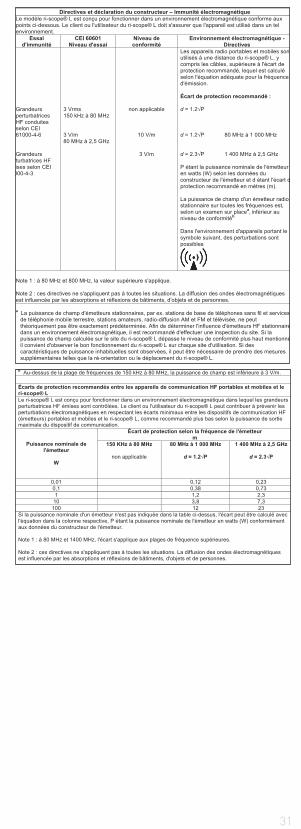
31
Directives et déclaration du constructeur – Immunité électromagnétique Le modèle ri-scope® L est conçu pour fonctionner dans un environnement électromagnétique conforme aux points ci-dessous. Le client ou l'utilisateur du ri-scope® L doit s'assurer que l'appareil est utilisé dans un tel environnement.
Essai d'immunité
CEI 60601 Niveau d'essai
Niveau de conformité
Environnement électromagnétique - Directives
Grandeurs perturbatrices HF conduites selon CEI 61000-4-6 Grandeurs
rturbatrices HF ises selon CEI
000-4-3
3 Vrms 150 kHz à 80 MHz 3 V/m 80 MHz à 2,5 GHz
non applicable
10 V/m
3 V/m
Les appareils radio portables et mobiles sontutilisés à une distance du ri-scope® L, y compris les câbles, supérieure à l'écart de protection recommandé, lequel est calculé selon l'équation adéquate pour la fréquence d'émission. Écart de protection recommandé : d = 1.2 P d = 1.2 P 80 MHz à 1 000 MHz d = 2.3 P 1 400 MHz à 2,5 GHz P étant la puissance nominale de l'émetteur en watts (W) selon les données du constructeur de l'émetteur et d étant l'écart dprotection recommandé en mètres (m). La puissance de champ d'un émetteur radio stationnaire sur toutes les fréquences est, selon un examen sur placea, inférieur au niveau de conformitéb
Dans l'environnement d'appareils portant le symbole suivant, des perturbations sont possibles
Note 1 : à 80 MHz et 800 MHz, la valeur supérieure s'applique. Note 2 : ces directives ne s'appliquent pas à toutes les situations. La diffusion des ondes électromagnétiques est influencée par les absorptions et réflexions de bâtiments, d'objets et de personnes. a La puissance de champ d'émetteurs stationnaires, par ex. stations de base de téléphones sans fil et services
de téléphonie mobile terrestre, stations amateurs, radio-diffusion AM et FM et télévisée, ne peut théoriquement pas être exactement prédéterminée. Afin de déterminer l'influence d'émetteurs HF stationnairedans un environnement électromagnétique, il est recommandé d'effectuer une inspection du site. Si la puissance de champ calculée sur le site du ri-scope® L dépasse le niveau de conformité plus haut mentionnéil convient d'observer le bon fonctionnement du ri-scope® L sur chaque site d'utilisation. Si des caractéristiques de puissance inhabituelles sont observées, il peut être nécessaire de prendre des mesures supplémentaires telles que la ré-orientation ou le déplacement du ri-scope® L.
b Au-dessus de la plage de fréquences de 150 kHz à 80 MHz, la puissance de champ est inférieure à 3 V/m.
Écarts de protection recommandés entre les appareils de communication HF portables et mobiles et le ri-scope® L Le ri-scope® L est conçu pour fonctionner dans un environnement électromagnétique dans lequel les grandeurs perturbatrices HF émises sont contrôlées. Le client ou l'utilisateur du ri-scope® L peut contribuer à prévenir les perturbations électromagnétiques en respectant les écarts minimaux entre les dispositifs de communication HF (émetteurs) portables et mobiles et le ri-scope® L, comme recommandé plus bas selon la puissance de sortie maximale du dispositif de communication.
Puissance nominale de l'émetteur
W
Écart de protection selon la fréquence de l'émetteur m
150 KHz à 80 MHz
non applicable
80 MHz à 1 000 MHz
d = 1.2 P
1 400 MHz à 2,5 GHz
d = 2.3 P
0,01 0,12 0,23 0,1 0,38 0,73 1 1,2 2,3
10 3,8 7,3 100 12 23
Si la puissance nominale d'un émetteur n'est pas indiquée dans la table ci-dessus, l'écart peut être calculé avec l'équation dans la colonne respective, P étant la puissance nominale de l'émetteur en watts (W) conformément aux données du constructeur de l'émetteur. Note 1 : à 80 MHz et 1400 MHz, l'écart s'applique aux plages de fréquence supérieures. Note 2 : ces directives ne s'appliquent pas à toutes les situations. La diffusion des ondes électromagnétiques est influencée par les absorptions et réflexions de bâtiments, d'objets et de personnes.

32
SPANISH
Información importante para tener en cuenta antes de la puesta en servicio
Ha adquirido un instrumento diagnóstico de alta calidad Riester que se ha fab-ricado de acuerdo con la Directiva 93/42/CEE para productos sanitarios y que se somete constantemente a las comprobaciones de calidad más estrictas. La ca-lidad excelente le garantizará diagnósticos fiables. En este manual del operador se describe el uso de los mangos de pilas Riester de los cabezales de instru-mentos ri-scope® o ri-derma® y de los accesorios correspondientes. Antes de la puesta en servicio, lea detenidamente el manual del operador y consérvelo cuidadosamente. Si tiene preguntas, nosotros o su representante de productos Riester le asesoraremos con mucho gusto en cualquier momento. Encontrará nuestra dirección en la última página de este manual del operador. A petición, le proporcionaremos la dirección de nuestro representante. Tenga en cuenta que todos los instrumentos descritos en este manual del operador deben ser utilizados exclusivamente por personas debidamente formadas. El otoscopio quirúrgico en el kit Vet-I es un instrumento que se ha fabricado exclusivamente para la medicina veterinaria y por lo tanto no posee una marca CE. Además, debe tener en cuenta que el funcionamiento correcto y seguro de nuestros inst-rumentos sólo se garantiza si se utilizan exclusivamente los instrumentos y los accesorios correspondientes de la casa Riester.
Indicaciones de seguridad:
¡Atención, tenga en cuenta el manual del operador! Equipo con doble puesta a tierra
Clasificación
Pieza de uso Tipo B Cabezal de otoscopio con espéculo
2. Mangos de pilas y puesta en servicio
2.1. Uso previsto
Los mangos de pilas Riester descritos en este manual del operador sirven para suministrar energía a los cabezales de instrumentos (las lámparas están in-tegradas en los cabezales de instrumentos correspondientes). Sirven además como soporte.
2.2. Surtido de mangos de pilas
Todos los cabezales de instrumentos descritos en este manual del operador se pueden acoplar a los mangos de pilas siguientes y, por lo tanto, combinar de forma individual. Además, todos los cabezales de instrumentos se pueden acoplar a los mangos del modelo mural ri-former®.Atención: Los cabezales de instrumentos LED sólo son compatibles a partir de un número de serie determinado de la unidad diagnóstica ri-former®. Si lo solicita, le proporcionaremos con mucho gusto información sobre la compatibi-lidad de su unidad diagnóstica.
Para otoscopios ri-scope®L, oftalmoscopios ri-scope®L, perfect, H.N.O,
praktikant, de luxe®, Vet, retinoscopios Slit y Spot, ri-vision®.
a) Mango de pilas Tipo C con rheotronic® 2,5 V. Para poder utilizar estos mangos de pilas necesita 2 pilas alcalinas usuales en el comercio del tipo C Baby (Designación según la norma IEC LR14) o un ri-accu® 2,5 V. El mango con el ri-accu® de Riester sólo se puede cargar en el cargador ri-charger® de Riester.
b) Mango de pilas Tipo C con rheotronic® 3,5 V. Para poder utilizar estos mangos de pilas necesita 2 pilas de litio usuales en el comercio del tipo CR 123A (Atención: solo con casquillo reductor + regulador LDO) o un ri-accu®L 3,5 V. El mango con el ri-accu®L de Riester sólo se puede cargar en el cargador ri-charger®L de Riester.
c) Mango de baterías recargable Tipo C 2,5 V o 3,5 V con reóstato para la carga en la toma de corriente de 230 V o 120 V. El mango está disponible como versión de 2,5 V o 3,5 V y se puede encargar para el funcionamiento con 230 V o 120 V. Tenga en cuenta que el mango sólo se puede utilizar con el ri-accu® o ri-accu®L de Riester.
d) Mango de pilas Tipo AA con rheotronic® 2,5 V. Para poder utilizar estos mangos de pilas necesita 2 pilas alcalinas usuales en el comercio del tipo C Baby (Designación según la norma IEC LR6) o un ri-accu® 2,5 V. El mango con el ri-accu® de Riester sólo se puede cargar en el cargador ri-charger® de Riester.
e) Mango de pilas Tipo AA con rheotronic® 3,5 V. Para poder utilizar estos mangos de pilas necesita 2 pilas de litio usuales en el comercio del tipo CR 123A (Atención, solo con un regulador LDO) o un ri-accu®L 3,5 V. El mango con el ri-accu®L de Riester sólo se puede cargar en el cargador ri-charger®L de Riester.
2.3. Introducción y extracción de las pilas y baterías recargables
Tipos de mango (2.2. a, b, d y e)Desenrosque la tapa del mango situada en parte inferior del mango. Según el mango que haya adquirido para el tipo de voltaje deseado (ver 2.2), introduzca las pilas o las baterías recargables correspondientes en la carcasa del mango
33
con los polos positivos dirigidos hacia la parte superior del mango. En la batería recargable encontrará además una flecha al lado del signo „Más“ que le indi-cará la dirección para la introducción en el mango. Vuelva a enroscar la tapa firmemente en el mango.Atención: Con pilas de litio (solo con mangos para pilas de tipo C) necesitará un reductor (n.º de art. 12652) + regulador LDO (n.º de art. 12653)
Mango C
En caso de conversión:
Desenrosque la tapa del mango situada en la parte inferior del mango.Para las pilas de litio, primero se coloca el casquillo reductor dentro del tubo del mango con el extremo situado donde apoya el anillo tensor del muelle, y el regulador LDO se inserta en la dirección de la flecha impresa. A continuación se introducen las pilas de litio de forma que el polo positivo apunte hacia la parte superior del mango. Vuelva a enroscar bien la tapa del mango en el mango.
Mango AA
En caso de conversión:
Desenrosque la tapa del mango situada en la parte inferior del mango.Para las pilas de litio, el regulador LDO se inserta en la dirección de la flecha impresa. A continuación se introducen las pilas de litio de forma que el polo positivo apunte hacia la parte superior del mango. Vuelva a enroscar bien la tapa del mango en el mango.
Para extraer las pilas, desenrosque la tapa del mango de pilas y agite ligera-mente el mango. Antes de la primera puesta en servicio, las baterías recargab-les (en el mango de pilas de Riester) se deben cargar en el cargador ri-char-ger® de Riester. Cada cargador incluye un manual del operador aparte que se debe tener en cuenta.Tipos de mango (2.2. c)
Antes de utilizar por primera vez el mango de enchufe deberá cargarlo en la toma de corriente durante un máximo de 24 horas.ATENCIÓN: El mango de enchufe (sólo en el caso de baterías recargables NiMH) se debe cargar como máximo durante 24 horas.
Desenrosque la tapa del mango situada en parte inferior del mango. Según el mango que haya adquirido para el tipo de voltaje deseado (ver 2.2), intro-duzca las baterías recargables correspondientes en la carcasa del mango. Si utiliza baterías recargables de 2,5 V, introduzca la batería recargable con el lado positivo dirigido hacia la parte superior del mango; al lado del signo „Más“ encontrará además una flecha que le indicará la dirección para la introducción en el mango. Para las baterías recargables de 3,5 V no importa la dirección de introducción. Vuelva a enroscar la tapa firmemente en el mango. Desenros-que la parte inferior del mango en el sentido contrario a las agujas del reloj. Aparecen los contactos de enchufe. Los contactos redondos se utilizan para el funcionamiento de red de 230 V, los contactos planos para el funcionamiento de red de 120 V. Introduzca ahora la parte inferior del mango para cargarlo en la toma de corriente.
ATENCIÓN: ¡Cuando cambie la batería recargable, el mango no debe estar nun-ca enchufado en la toma de corriente!
Si desea cambiar el ri-accu®, desenrosque la tapa del mango de pilas situada en la parte inferior del mango en el sentido contrario a las agujas del reloj. Para extraer el ri-accu® del mango de pilas, agite ligeramente el mango. In-troduzca el ri-accu® en el mango de pilas. Si utiliza baterías recargables de 2,5 V, introduzca la batería recargable con el lado positivo dirigido hacia la parte superior del mango; al lado del signo „Más“ encontrará además una flecha que le indicará la dirección para la introducción en el mango. Para las baterías recargables de 3,5 V no importa la dirección de introducción. Enrosque la tapa del mango de pilas firmemente en sentido horario en el mango.Datos técnicos: Opcionalmente 230 V o 120 V
ATENCIÓN:
• Si no va a utilizar el equipo durante un tiempo prolongado o desea llevárselo en sus viajes, extraiga las pilas y baterías recargables del mango.• Introduzca baterías nuevas si disminuye la intensidad luminosa del instrumento.• Para obtener un rendimiento lumínico óptimo, recomendamos que utilice siempre pilas nuevas de alta calidad (como se describe en 2.2.).• Si sospecha que podría haber penetrado líquido o agua de condensación en el mango, no lo cargue. Se pueden producir descargas eléctricas peligrosas, sobre todo en los mangos de enchufe.• Para prolongar la vida útil del ri-accu®, cargue el ri-accu® sólo si disminuye la intensidad luminosa del instrumento.
Eliminación:
Tenga en cuenta que las pilas y las baterías recargables se deben eliminar de forma adecuada. Para obtener información al respecto pregunte en su ayunta-miento o consulte a su asesor del medio ambiente.
2.4. Montaje de los cabezales de instrumentos
Inserte el cabezal de instrumentos deseado en el alojamiento de la parte su-perior del mango, introduciendo las dos escotaduras de la parte inferior del cabezal de instrumentos en las dos pestañas guía que sobresalen del mango de pilas. Presione el cabezal de instrumentos ligeramente sobre el mango de pilas
34
y gire el mango hasta el tope en sentido horario. Desmonte el cabezal girándolo en el sentido contrario a las agujas del reloj.
2.5 Conexión y desconexión
Mangos de pilas Tipo C y AA Encienda el instrumento tocando el anillo de en-cendido en dirección al avance de las manecillas del reloj. Para apagar el in-strumento toque el anillo en contra de las manecillas del reloj hasta que el aparato se apague.
2.6. rheotronic® para regular la intensidad de la luz
Con ayuda del rheotronic es posible ajustar la intensidad de la luz en los man-gos a baterias tipo C y AA. De acuerdo a la frecuencia en que usted toque el anil-lo de encendido, en contra o en dirección a las manecillas del reloj, la intencidad de luz será mas tenue o mas fuerte.ATENCIÓN: Cada vez que se encienda el mango a baterias la intensidad de la luz iniciara al 100%. Apagado automático de seguridad después de 180 segundos.
Explicación del signo situado en el mango de enchufe: ATENCIÓN, tenga en cuenta el manual del operador!
3. Otoscopio ri-scope®L3.1. Uso previsto
El otoscopio Riester que se describe en el manual del operador sirve para ilu-minar y examinar el conducto auditivo en combinación con los espéculos au-riculares Riester.
3.2. Montaje y desmontaje de los espéculos auriculares
Para el cabezal del otoscopio se pueden seleccionar opcionalmente espéculos desechables Riester (azules) o espéculos reutilizables Riester (negros). El ta-maño del espéculo auricular se indica en la parte posterior del espéculo. Otos-copio L1 y L2 Gire el espéculo en sentido horario hasta que note resistencia. Para poder desmontar el espéculo, gírelo en sentido antihorario. Otoscopio L3 Introduzca el espéculo seleccionado en el soporte metálico cromado del otos-copio hasta que encaje perceptiblemente. Para poder desmontar el espéculo, pulse la tecla de expulsión azul. El espéculo se expulsa automáticamente.
3.3. Lente giratoria de ampliación
La lente giratoria está unida de forma fija al instrumento y se puede girar 360°.
3.4. Introducción de instrumentos externos en el oído
Si desea introducir instrumentos externos en el oído (p. ej. unas pinzas), debe girar 180° la lente giratoria (aprox. 3 aumentos) que se encuentra en el otosco-pio. Ahora puede introducir la lente quirúrgica.
3.5. Prueba neumática
Para poder realizar la prueba neumática (un examen del tímpano) necesita una pera que no se incluye en el volumen de suministro normal pero que podrá en-cargar opcionalmente. El tubo de la pera se inserta en el conector. Ahora puede introducir con cuidado la cantidad de aire necesaria en el conducto auditivo.
3.6 Datos técnicos de la lámpara
Otoscopio XL 2,5V 2,5 V 750 mA promedio vida útil 15 hOtoscopio XL 3,5V 3,5 V 720 mA promedio vida útil 15 hOtoscopio LED 3,5V 3,5 V 28 mA promedio vida útil 10000 h
4. Oftalmoscopio ri-scope®L4.1. Uso previsto
El oftalmoscopio Riester descrito en este manual del operador sirve para exa-minar el ojo y el fondo del ojo.
4.2. Rueda de lentes con lentes de corrección
Las lentes de corrección se pueden ajustar en la rueda de lentes. Puede selec-cionar las lentes de corrección siguientes:
Oftalmoscopio L1 y L2
D+: 1-10, 12, 15, 20, 40.D-: 1-10, 15, 20, 25, 30, 35.
Oftalmoscopio L3
D+: 1-45 en pasos individualesD-: 1-44 en pasos individuales
Los valores se pueden leer en el campo de indicación iluminado. Los valores positivos se indican con números verdes, los valores negativos con números rojos.
4.3. Diafragmas
Con la ruedecilla de diafragmación puede seleccionar los diafragmas siguien-tes:
Oftalmoscopio L1
Semicírculo, diafragma circular pequeño/mediano/grande, estrella de fijación, rendija.
Oftalmoscopio L2
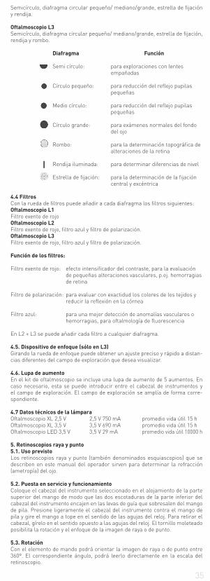
35
Semicírculo, diafragma circular pequeño/ mediano/grande, estrella de fijación y rendija.
Oftalmoscopio L3
Semicírculo, diafragma circular pequeño/ mediano/grande, estrella de fijación, rendija y rombo.
Diafragma Función
Semi círculo: para exploraciones con lentes empañadas
Círculo pequeño: para reducción del reflejo pupilas pequeñas
Medio círculo: para reducción del reflejo pupilas pequeñas
Círculo grande: para exámenes normales del fondo del ojo
Rombo: para la determinación topográfica de alteraciones de la retina
Rendija iluminada: para determinar diferencias de nivel
Estrella de fijación: para la determinación de la fijación central y excéntrica
4.4 Filtros
Con la rueda de filtros puede añadir a cada diafragma los filtros siguientes:Oftalmoscopio L1
Filtro exento de rojoOftalmoscopio L2
Filtro exento de rojo, filtro azul y filtro de polarización.Oftalmoscopio L3
Filtro exento de rojo, filtro azul y filtro de polarización.
Función de los filtros:
Filtro exento de rojo: efecto intensificador del contraste, para la evaluación de pequeñas alteraciones vasculares, p.ej. hemorragias de retina
Filtro de polarización: para evaluar con exactidud los colores de los tejidos y reducir la reflexión en la córnea
Filtro azul: para una mejor detección de anomalías vasculares o hemorragias, para oftalmología de fluorescencia
En L2 + L3 se puede añadir cada filtro a cualquier diafragma.
4.5. Dispositivo de enfoque (sólo en L3)
Girando la rueda de enfoque puede obtener un ajuste preciso y rápido a distan-cias diferentes del campo de exploración que desea visualizar.
4.6. Lupa de aumento
En el kit de oftalmoscopio se incluye una lupa de aumento de 5 aumentos. En caso necesario, esta se puede introducir entre el cabezal de instrumentos y el campo de exploración. El campo de exploración se amplía de forma corre-spondiente.
4.7 Datos técnicos de la lámpara
Oftalmoscopio XL 2,5 V 2,5 V 750 mA promedio vida útil 15 hOftalmoscopio XL 3,5 V 3,5 V 690 mA promedio vida útil 15 hOftalmoscopio LED 3,5 V 3,5 V 29 mA promedio vida útil 10000 h
5. Retinoscopios raya y punto
5.1. Uso previsto
Los retinoscopios raya y punto (también denominados esquiascopios) que se describen en este manual del operador sirven para determinar la refracción (ametropía) del ojo.
5.2. Puesta en servicio y funcionamiento
Coloque el cabezal del instrumento seleccionado en el alojamiento de la parte superior del mango de modo que las dos escotaduras de la parte inferior del cabezal del instrumento encajen en las levas de guía que sobresalen del mango de pila. Presione ligeramente el cabezal del instrumento contra el mango de pila y gire el mango a tope en el sentido de las agujas del reloj. Para retirar el cabezal, gírelo en el sentido opuesto a las agujas del reloj. El tornillo moleteado posibilita la rotación y el enfoque de la imagen de raya o de punto.
5.3. Rotación
Con el elemento de mando podrá orientar la imagen de raya o de punto entre 360º. El correspondiente ángulo, podrá leerlo directamente en la escala del retinoscopio.
36
5.4 Carta de fijación
Para el esquiascopio dinámica, se cuelgan y se fijan las cartas de fijación por el lado del objetivo del retinoscopio.
5.5 Datos técnicos de la lámpara
Retinoscopio de raya (slit) HL 2,5 V 2,5 V 440 mA promedio vida útil 15 hRetinoscopio de raya (slit) XL 3,5 V 3,5 V 690 mA promedio vida útil 50 hRetinoscopio de punto (spot) HL 2,5 V 2,5 V 450 mA promedio vida útil 15 hRetinoscopio de punto (spot) XL 3,5 V 3,5 V 640 mA promedio vida útil 40 h
6. Dermatoscopio
6.1. Uso previsto
El dermatoscopio ri-derma® descrito en este manual del operador sirve para la detección precoz de lesiones pigmentadas de la piel (melanomas malignos).
6.2. Puesta en servicio y funcionamiento
Coloque el cabezal del instrumento seleccionado en el alojamiento de la parte superior del mango de modo que las dos escotaduras de la parte inferior del cabezal del instrumento encajen en las levas de guía que sobresalen del mango de pila. Presione ligeramente el cabezal del instrumento contra el mango de pila y gire el mango a tope en el sentido de las agujas del reloj. Para retirar el cabezal, gírelo en el sentido opuesto a las agujas del reloj.
6.3. Enfoque
Enfoque la lupa girando para ello el anillo del ocular.
6.4. Contactos sobre la piel
El instrumento se suministra con dos contactos sobre la piel:1) Con graduación de 0-10 mm para medir cambios de pigmentación cutánea como melanomas malignos.2) Sin graduación. Ambos contactos sobre la piel son extraíbles e intercambiables.
6.5 Datos técnicos de la lámpara
ri-derma® XL 2,5 V 2,5 V 750 mA promedio vida útil 15 hri-derma® XL 3,5 V 3,5 V 690 mA promedio vida útil 15 hri-derma® LED 3,5 V 3,5 V 28 mA promedio vida útil 10000 h
7. Portalámparas
7.1. Uso previsto
El portalámparas Riester descrito en este manual del operador sirve para ilu-minar la cavidad bucal y la faringe.
7.2. Puesta en servicio y funcionamiento
Coloque el cabezal del instrumento seleccionado en el alojamiento de la parte superior del mango de modo que las dos escotaduras de la parte inferior del cabezal del instrumento encajen en las levas de guía que sobresalen del mango de pila. Presione ligeramente el cabezal del instrumento contra el mango de pila y gire el mango a tope en el sentido de las agujas del reloj. Para retirar el cabezal, gírelo en el sentido opuesto a las agujas del reloj.
7.3 Datos técnicos de la lámpara
Portalámpara XL 2,5 V 2,5 V 750 mA promedio vida útil 15 hPortalámpara XL 3,5 V 3,5 V 690 mA promedio vida útil 15 hPortalámpara LED 3,5 V 3,5 V 28 mA promedio vida útil 10000 h
8. Espéculo nasal
8.1. Uso previsto
El espéculo nasal descrito en este manual del operador sirve para iluminar y, por lo tanto, para examinar el interior de la nariz.
8.2. Puesta en servicio y funcionamiento
Coloque el cabezal del instrumento seleccionado en el alojamiento de la parte superior del mango de modo que las dos escotaduras de la parte inferior del cabezal del instrumento encajen en las levas de guía que sobresalen del mango de pila. Presione ligeramente el cabezal del instrumento contra el mango de pila y gire el mango a tope en el sentido de las agujas del reloj. Para retirar el cabezal, gírelo en el sentido opuesto a las agujas del reloj. El espéculo se puede utilizar de dos formas:
a) Expansión rápida Con el pulgar, empuje hacia abajo el tornillo de ajuste ubicado en el cabezal del instrumento. Con este ajuste no se podrá modificar la posición de la pata del especulo.b) Expansión individual Gire el tornillo de ajuste en el sentido de a las agujas del reloj hasta alcanzar la apertura de expansión conveniente. Las patas se cierran de nuevo cuando se gira el tornillo en el sentido opuesto a las agujas del reloj.
8.3 Lente giratoria
El espéculo nasal esta dotado de una lente giratoria de aproximadamente 2,5 aumentos. En caso necesario, esta lente se puede retirar y/o volver a colocar en el agujero provisto a tal efecto.
8.4 Datos técnicos de la lámpara
Espéculo nasal XL 2,5 V 2,5 V 750 mA promedio vida útil 15 hEspéculo nasal XL 3,5 V 3,5 V 690 mA promedio vida útil 15 h

37
Espéculo nasal LED 3,5 V 3,5 V 28 mA promedio vida útil 10000 h
9. Portaespátulas
9.1. Uso previsto
El portaespátulas descrito en este manual del operador sirve para examinar la cavidad bucal y la faringe en combinación con las espátulas de madera o plástico usuales en el comercio.
9.2. Puesta en servicio y funcionamiento
Coloque el cabezal del instrumento seleccionado en el alojamiento de la parte superior del mango de modo que las dos escotaduras de la parte inferior del cabezal del instrumento encajen en las levas de guía que sobresalen del mango de pila. Presione ligeramente el cabezal del instrumento contra el mango de pila y gire el mango a tope en el sentido de las agujas del reloj. Para retirar el cabezal, gírelo en el sentido opuesto a las agujas del reloj. Introduzca una espátula corriente de madera o de plástico a tope en el agujero ubicado por debajo de la salida de luz. Una vez concluido el reconocimiento, podrá extraer la espátula activando simplemente el expulsor.
9.3 Datos técnicos de la lámpara
Portaespátula XL 2,5 V 2,5 V 750 mA promedio vida útil 15 hPortaespátula XL 3,5 V 3,5 V 690 mA promedio vida útil 15 hPortaespátula LED 3,5 V 3,5 V 28 mA promedio vida útil 10000 h
10. Laringoscopio
10.1. Uso previsto
El laringoscopio descrito en este manual del operador sirve para la reflexión o el examen de la cavidad bucal y de la faringe en combinación con el portalám-paras Riester.
10.2. Puesta en servicio
Los espejos laríngeos se utilizarán exclusivamente en combinación con el portalámpara. Con ello se garantiza una óptima iluminación de esta cavidad. Inserte uno de los 2 laringoscopios en la dirección deseada, en la parte anterior del portalámparas. 11. Otoscopio quirúrgico para medicina veterinaria
11.1. Uso previsto
El otoscopio quirúrgico Riester descrito en este manual del operador se utiliza exclusivamente en animales o en medicina veterinaria y, por lo tanto, no tiene una marca CE. Sirve para iluminar y examinar el conducto auditivo y realizar intervenciones quirúrgicas pequeñas en el conducto auditivo.
11.2. Cómo colocar y retirar los espéculos auditivos en veterinaria
Coloque el espéculo conveniente en la sujeción negra del otoscopio de opera-ción de modo que la escotadura del espéculo encaje en la guía de la sujeción. Fije el espéculo, girándolo para ello en el sentido opuesto a las agujas del reloj.
11.3. Lente de aumento giratoria
El otoscopio de operación dispone de una lente de ampliación con aproximada-mente 2,5 aumentos, orientable entre 360º.
11.4. Introducción de instrumentos externos en el oído
El otoscopio quirúrgico tiene un diseño abierto y permite de este modo la intro-ducción de instrumentos externos en el oído del animal.
11.5 Datos técnicos de la lámpara
Otoscopio operación HL 2,5 V 2,5 V 680 mA promedio vida útil 20 hOtoscopio operación XL 3,5 V 3,5 V 700 mA promedio vida útil 20 h
12. Otoscopio quirúrgico para medicina humana
12.1. Uso previsto
El otoscopio quirúrgico Riester descrito en este manual del operador sirve para iluminar y examinar el conducto auditivo e introducir instrumentos externos en el mismo.
12.2 Colocación y extracción de los espéculos auriculares en medicina hu-
mana
Coloque el espéculo deseado sobre el soporte negro del otoscopio quirúrgico de modo que la muesca del espéculo coincida conla guía del soporte. Fije el espéculo girándolo en sentido contrario a las agujas del reloj.
12.3 Lente de aumento pivotante
El otoscopio qurúrgico dispone de una pequeña lente de aproximadamente 2,5 aumentos que puede pivotarse 360°.
12.4. Introducción de instrumentos externos en el oído
El diseño del otoscopio quirúrgico permite la introducción de instrumentos ex-ternos en el oído.
12.5 Datos técnicos de la lámpara
Otoscopio operación HL 2,5 V 2,5 V 680 mA promedio vida útil 20 hOtoscopio operación XL 3,5 V 3,5 V 700 mA promedio vida útil 20 h
13. Cambio de la lámpara
Otoscopio L1
38
Desmonte el soporte del espéculo del otoscopio. Gire la lámpara en el sentido contrario a las agujas del reloj. Enrosque la nueva lámpara en sentido horario y vuelva a montar el soporte del espéculo.
Otoscopios L2, L3, ri-derma®, portalámparas, espéculo nasal y portaespátu-
las
Desenrosque el cabezal de instrumentos del mango de pilas. La lámpara se encuentra en la parte inferior del cabezal de instrumentos. Extraiga la lámpara con el pulgar y el dedo índice o con una herramienta adecuada del cabezal de instrumentos. Introduzca firmemente la nueva lámpara.
Oftalmoscopios
Desmonte el cabezal de instrumentos del mango de pilas. La lámpara se en-cuentra en la parte inferior del cabezal de instrumentos. Extraiga la lámpara con el pulgar y el dedo índice o con una herramienta adecuada del cabezal de instrumentos. Introduzca firmemente la nueva lámpara.ATENCIÓN: El borne de la lámpara se debe introducir en la ranura guía del cabezal de ins-trumentos.
Otoscopios quirúrgicos medicina veterinaria/humana
Desenrosque la lámpara del zócalo del otoscopio quirúrgico y enrosque la nu-eva lámpara.
14. Recomendaciones para la conservación
Indicaciones generales
La limpieza y la desinfección de los productos sanitarios protegen al paciente, al usuario y a terceros y conservan el valor de dichos productos.Debido al diseño del producto y de los materiales utilizados no se puede esta-blecer un límite definido de número máximo de ciclos de reacondicionamiento que se pueden realizar. La vida útil de los productos sanitarios viene determina-da por su función y por un manejo cuidadoso.Los productos defectuosos deben reacondicionarse de la forma descrita antes de devolverse para su reparación.
Limpieza y desinfección
El cabezal del instrumento y mango se pueden limpiar por fuera con un paño húmedo hasta que se aprecie visualmente que están limpios.Realice la desinfección con un paño según las especificaciones del fabricante del desinfectante. Se deben utilizar exclusivamente productos de eficacia pro-bada y teniendo en cuenta los requisitos nacionales.Tras la desinfección, limpie el instrumento con un paño húmedo para eliminar los posibles restos de desinfectante.
Las piezas para examinar la piel (ri-derma®) se puede frotar con alcohol o con un desinfectante adecuado.
ATENCIÓN:
• ¡No sumerja nunca el cabezal del instrumento ni el mango en líquidos! ¡Tenga cuidado de que no penetre ningún líquido en el interior de la carcasa!• El artículo no está aprobado para la esterilización ni el reacondicionamiento automáticos. ¡Podrían producirse daños irreparables!
Esterilización
a) Espéculos reutilizables Los espéculos se pueden esterilizar a 134 °C y un tiempo de actuación de 10 minutos en un esterilizador por vapor.b) Espéculos de un solo uso Exclusivamente para un solo uso
ATENCIÓN: el uso repetido puede producir infección.
15. Recambios y accesorios
Una lista detallada se encontra en nuestro folleto Instrumentos para ORL y of-talmologia, que Uds. pueden descargar vía www.riester.de
16. Mantenimiento
Los instrumentos y sus correspondientes accesorios no precisan de ningún mantenimiento especial. Si por cualquier motivo fuera necesario someter el instrumento a inspección, por favor diríjase a nuestra empresa o a un represen-tante reconocido por Riester; le asistiremos gustosamente.
17. Indicaciones
Temperatura ambiente: 0 ° a +40 °Humedad relativa: 30 % a 70 % sin condensaciónTemperatura de transporte yalmacenamiento: - 10 ° a +55 °Humedad relativa: 10 % a 95 % sin condensación
18 Compatibilidad electromagnética
Los equipos electromédicos deben cumplir unas medidas de precaución espe-ciales en cuanto a la compatibilidad electromagnética (CEM). Los equipos de comunicación de alta frecuencia portátiles y móviles pueden influir sobre los equipos de electromedicina. El presente equipo electromédico ha sido conce-bido para el uso en un entorno electromagnético como el que se describe a
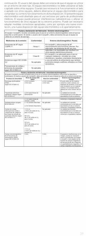
39
continuación. El usuario del equipo debe cerciorarse de que el equipo se utilice en un entorno de este tipo. El equipo electromédico no debe utilizarse al lado o apilado sobre otros equipos. Cuando sea necesario el funcionamiento al lado o apilado con otros equipos, deberá observarse el equipo electromédico para comprobar su correcto funcionamiento en dicha disposición. El presente equipo electromédico está diseñado para el uso exclusivo por parte de profesionales médicos. El equipo puede provocar interferencias radioeléctricas o alterar el funcionamiento de otros equipos de su entorno próximo. Puede ser necesario adoptar medidas correctoras apropiadas, como por ejemplo una nueva orien-tación, una nueva disposición del equipo electromédico o el apantallamiento.
Pautas y declaración del fabricante - Emisión electromagnética El equipo ri-scope® L ha sido concebido para el uso en un entorno electromagnético como el que se describe a continuación. El cliente o usuario del ri-scope® L debe cerciorarse de que el equipo se utilice en un entorno de ese tipo.
Mediciones de la emisión
Conformidad
Entorno electromagnético: Pautas
Emisiones de AF según CISPR 11
Grupo 1
El ri-scope® L utiliza energía de AF exclusivamente para funciones internas. Por esta razón, las emisiones de AF son muy reducidas y es improbable que interfiera con otros equipos electrónicos próximos.
Emisiones de AF según CISPR 11
Clase B
El ri-scope® L es adecuado para el uso en cualquier instalación, incluidas las zonas domésticas y aquellas conectadas directamente a una red pública de alimentación que también suministre energía a edificios utilizados con fines domésticos.
Armónicos según IEC 61000-3-2
No aplicable
Fluctuaciones de voltaje y emisiones de parpadeo según IEC 61000-3-3
No aplicable
Pautas y declaración del fabricante - Inmunidad electromagnética El equipo ri-scope® L ha sido concebido para el uso en un entorno electromagnético como el que se describe a continuación. El cliente o usuario del ri-scope® L debe cerciorarse de que el equipo se utilice en un entorno de ese tipo.
Pruebas de inmunidad Nivel de ensayo IEC 60601 Nivel de conformidad Entorno electromagnético:
Pautas Descarga electrostática (ESD) según IEC 61000-4-2
± 6 kV contacto ± 8 kV aire
± 6 kV contacto ± 8 kV aire
El suelo debe ser de madera, cemento o estar cubierto con baldosas de cerámica. Si el suelo está recubierto con un material sintético, la humedad relativa deberá ser como mínimo del 30 %.
Transitorias eléctricas rápidas/en ráfagas según IEC 61000-4-4
± 2 kV para líneas de alimentación
No aplicable La calidad de la tensión suministrada por la red debe ser equivalente a la de un entorno
± 1 kV para líneas de entrada y salida
comercial u hospitalario habitual.
Sobretensiones (surges) IEC61000-4-5
± 1 kV tensión fase-fase ± 2 kV tensión fase-tierra
No aplicable La calidad de la tensión suministrada por la red debe ser equivalente a la de un entorno comercial u hospitalario habitual.
Caídas de voltaje, interrupciones cortas y variaciones de voltaje en las líneas de entrada de suministro eléctrico según IEC 61000-4-11
< 5 % UT (> 95 % de caída en UT) para 1/2 ciclo 40 % UT (60 % de caída en UT) para 5 ciclos 70 % UT (30 % de caída en UT) para 25 ciclos < 5 % UT (> 95 % de caída en UT) durante 5 s
No aplicable
La calidad de la tensión suministrada por la red debe ser equivalente a la de un entorno comercial u hospitalario habitual.
Campo electromagnético de la frecuencia de alimentación (50Hz) según IEC 61000-4-8
3 A/m 3 A/m Si aparecen interferencias en la imagen, puede ser necesario situar el amplificador de imagen ri-scope® L más alejado de las fuentes de campos magnéticos de frecuencia de red o disponer un apantallamiento magnético. El campo magnético de frecuencia
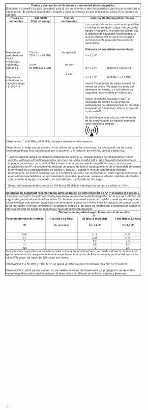
40
Pautas y declaración del fabricante - Inmunidad electromagnética El modelo ri-scope® L ha sido concebido para el uso en un entorno electromagnético como el que se describe a continuación. El cliente o usuario del ri-scope® L debe cerciorarse de que el equipo se utilice en un entorno de ese tipo.
Prueba de inmunidad
IEC 60601 Nivel de ensayo
Nivel de conformidad
Entorno electromagnético: Pautas
Magnitudes perturbadoras de AF conducidas según IEC 61000-4-6 Magnitudes
rturbadoras de radiadas según
C 61000-4-3
3 Vrms 150 kHz a 80 MHz 3 V/m 80 MHz a 2,5 GHz
No aplicable
10 V/m
3 V/m
Los aparatos de radiocomunicación portátiles y móviles no se deben utilizar más cerca del equipo ri-scope® L, incluidos los cables, que la distancia de seguridad recomendada, la cual se calcula con ayuda de la ecuación correspondiente para esta frecuencia de transmisión. Distancia de seguridad recomendada: d = 1,2 P d = 1,2 P 80 MHz a 1000 MHz d = 2,3 P 1400 MHz a 2,5 GHz siendo P la potencia de salida nominal del emisor en vatios (W) según los datos del fabricante del mismo, y d la distancia de seguridad recomendada en metros (m). Según un estudio realizado in situa, la intensidad de campo de los emisores estacionarios de radiofrecuencia es, en todas las gamas de frecuencias, inferior al nivel de conformidadb.
Es posible que se produzcan interferencias en las proximidades de equipos marcados con el siguiente símbolo
Observación 1: a 80 MHz y 800 MHz, se aplica siempre el valor superior. Observación 2: estas pautas pueden no ser válidas en todas las situaciones. La propagación de las ondas electromagnéticas está condicionada por la absorción y la reflexión de edificios, objetos y personas. a La intensidad de campo de emisores estacionarios como p. ej. estaciones base de radiotelefonía y redes
móviles, estaciones de radioaficionados, así como emisores de radio AM y FM, y televisión teóricamente no se puede determinar con exactitud. Para determinar el entorno electromagnético creado por emisores estacionarios de AF, se recomienda efectuar un ensayo de todo el emplazamiento. Si la intensidad de campo determinada en el emplazamiento del equipo ri-scope® L supera el nivel de conformidad indicado anteriormente, se deberá observar que el ri-scope® L funcione con normalidad en cada lugar de utilización. Sse observan características de funcionamiento inusuales, puede ser necesario adoptar medidas adicionales, como orientar el equipo ri-scope® L en otra dirección o colocarlo en otro lugar.
b Dentro del intervalo de frecuencia de 150 kHz a 80 MHz la intensidad de campo es inferior a 3 V/m.
Distancias de seguridad recomendadas entre aparatos de comunicación de AF y el equipo ri-scope® L. El equipo ri-scope® L ha sido concebido para el uso en un entorno electromagnético en el que se controlan las magnitudes perturbadoras de AF radiadas. El cliente o usuario del equipo ri-scope® L puede ayudar a que se eviten interferencias electromagnéticas manteniendo una distancia mínima entre los equipos de comunicación de AF portátiles y móviles (emisores) y el equipo ri-scope® L, tal como se recomienda a continuación según la potencia máxima de salida del respectivo equipo de radiocomunicación.
Potencia nominal del emisor
W
Distancia de seguridad según la frecuencia de emisión m
150 kHz a 80 MHz
No aplicable
80 MHz a 1000 MHz
d = 1,2 P
1400 MHz a 2,5 GHz
d = 2,3 P
0,01 0,12 0,23 0,1 0,38 0,73 1 1,2 2,3
10 3,8 7,3 100 12 23
Para emisores cuya potencia nominal no está indicada en la tabla anterior, se puede calcular la distancia con ayuda de la ecuación que pertenece en la respectiva columna, donde P es la potencia nominal del emisor en vatios (W) según los datos del fabricante del mismo.
Observación 1: a 80 MHz y 1400 MHz, se aplica la distancia para el intervalo más alto de frecuencia.
Observación 2: estas pautas pueden no ser válidas en todas las situaciones. La propagación de las ondas electromagnéticas está condicionada por la absorción y la reflexión de edificios, objetos y personas.
41
ITALIAN
1.Importanti informazioni da rispettare prima dell‘uso
Avete acquistato uno strumento diagnostico Riester di alta qualità, realizzato ai sensi della direttiva 93/42/CEE per Prodotti medicali e sottoposto a costanti controlli di qualità. La straordinaria qualità garantisce la massima affidabilità diagnostica. Nel presente libretto di istruzioni è descritto l’utilizzo die manici portabatterie Riester delle teste strumenti riscope® e riderma® e dei relativi accessori. Vi preghiamo di leggere attentamente questo libretto prima di mette-re in funzione lo strumento e di conservarlo con cura per futuro riferimento. In caso di domande, non esitate a contattarci oppure rivolgetevi al rappresentante autorizzato dei prodotti Riester. Il nostro indirizzo è riportato sull’ultima pagina del presente libretto di istruzioni. L’indirizzo del nostro rappresentante potrà essere comunicato su richiesta. Si ricorda che l’impiego di tutti gli strumenti descritti nel presente libretto di istruzioni è destinato esclusivamente a per-sonale opportunamente addestrato. L’otoscopio operatorio del set Vet-I è uno strumento prodottoesclusivamente per la medicina veterinaria e che pertanto non reca alcun mar-chio CE. Si ricorda inoltre che il perfetto funzionamento dei nostri strumenti può essere assicurato soltanto se si utilizzano esclusivamente strumenti e ac-cessori originali Riester.
Avvertenze di sicurezza:
Attenzione, leggere le istruzioni per l’uso!
Doppia protezione di messa a terra dell’apparecchio
Classificazione
Parte applicata di tipo B Testa otoscopio con specolo
2. Manico portabatterie e messa in funzione
2.1. Uso previsto
I manici portabatterie Riester descritti nel presente libretto d’istruzioni consen-tono di alimentare le teste degli strumenti (le ampadine sono contenute nelle rispettive teste). Fungono anche da supporto.
2.2. Gamma di manici portabatterie
Tutte le teste degli strumenti illustrate in questo libretto !di istruzioni si adattano ai seguenti manici portabatterie e possono pertanto es-sere combinate a piacere. Tutte le teste si adattano anche ai manici del modello a parete ri-former®.ATTENZIONE: Le teste a LED sono compatibili con la stazione diagnostica ri-former® soltanto a partire da un determinato numero di serie. Le informa-zioni sulla compatibilità di questa stazione diagnostica potranno essere comu-nicate su richiesta. per otoscopio ri-scope®L, oftalmoscopio ri-scope®L, perfect, O.R.L., praktikant, de luxe®, Vet, retinoscopio Slit e Spot, ri-vision®
a) Manico portabatterie tipo C con rheotronic® 2,5 V Questo manico portabat- terie funziona con 2 normali batterie alcaline di tipo C Baby (denominazione IEC LR14) o una batteria ricaricabile ri-accu® da 2,5 V. Il manico con ri-accu® di Riester può essere ricaricato soltanto nel caricabatterie ri-charger® di Riester.
b) Manico portabatterie tipo C con rheotronic® da 3,5 V Questo manico porta- batterie funziona con 2 normali batterie al litio tipo CR 123A (Attenzione: solo con inserto di riduzione + regolatore LDO) o una batteria ricaricabile ri-accu®L da 3,5 V. Il manico con ri-accu®L di Riester può essere caricato solo nel caricabatterie ri-charger® di Riester.
c) Manico portabatterie ricaricabile tipo C 2,5 V o 3,5 V con rheotronic® per la ricarica nella presa da 230 V o 120 V Il manico è disponibile nella versione da 2,5 V o 3,5 V e può essere ordinato per utilizzo a 230 V o 120 V. Fare attenzione che il manico può essere azionato esclusivamente con batterie ricaricabili ri-accu® o ri-accu®L di Riester.
d) Manico portabatterie tipo AA con rheotronic® da 2,5 V Questo manico por- tabatterie funziona con 2 normali batterie alcaline di tipo AA Baby (denomi- nazione IEC LR6) o una batteria ricaricabile ri-accu® da 2,5 V. Il manico con ri-accu® di Riester può essere ricaricato soltanto nel caricabatterie ri-charger® di Riester.
e) Manico portabatterie tipo AA con rheotronic® da 3,5 V Questo manico por- tabatterie funziona con 2 normali batterie al litio tipo CR 123A (Attenzione: solo con un regolatore LDO) o una batteria ricaricabile ri-accu®L da 3,5 V. Il manico con ri-accu®L di Riester può essere caricato solo nel caricabatterie ri-charger® di Riester.
42
2.3. Inserimento ed estrazione di batterie e batterie ricaricabili – tipi di ma-
nici (2.2. a, b, d, e)
Ruotare il coperchio situato sul fondo del manico portabatterie. A seconda del manico acquistato e della tensione esistente (vedere 2.2), inserire nell’apposito vano le rispettive batterie a perdere o la corrispondente batteria ricaricabile in modo che il polo positivo sia rivolto verso la parte superiore del manico. Sulla batteria ricaricabile, accanto al segno più è riportata anche una freccia, che indica la direzione di inserimento nel manico. Richiudere a fondo il coperchio ruotandolo sul manico.
ATTENZIONE: In caso di batterie al litio (solo per manici portabatterie tipo C) è necessario disporre di un inserto di riduzione (Art. n°: 12652) + regolatore LDO (Art. n°: 12653)Per togliere le batterie, ruotare il coperchio del manico portabatterie e poi scuotere leggermente il manico. Prima della prima messa in funzione occorre ricaricare le batterie ricaricabili (nel manico portabatterie di Riester) nel cari-cabatterie ri-charger® di Riester. Ogni caricabatterie è dotato di un apposito libretto di istruzioni, da leggere attentamente.
Tipi di manici (2.2. c) Prima della prima messa in funzione del manico portapresa si raccomanda di ricaricarlo nella presa al massimo per 24 ore.
ATTENZIONE: Il manico portapresa (solo per batterie ricaricabili NiMH) non può essere ricaricato per più di 24 ore.
Ruotare il coperchio situato sul fondo del manico portabatterie. A seconda del manico acquistato e della tensione esistente (vedere 2.2), inserire nell’apposito vano le rispettive batterie ricaricabili. In caso di batterie ricaricabili da 2,5 V, fare attenzione a inserirle con il polo positivo rivolto in direzione della parte superiore del manico; accanto al segno più è riportata anche una freccia che indica la direzione di inserimento. Nelle batterie ricaricabili da 3,5 V non occorre fare attenzione alla direzione di inserimento. Richiudere a fondo il coperchio ruotandolo sul manico.Svitare la parte inferiore del manico ruotando in senso antiorario. Risultano visibili i contatti della presa. I contatti rotondi sono destinati all’alimentazione di rete di 230 V, quelli piatti a 120 V. Innestare la parte inferiore del manico nella presa per la ricarica.ATTENZIONE: Quando si sostituiscono le batterie, il manico non deve mai trovarsi nella presa! Per sostituire la batteria ricaricabile ri-accu®, svitare il coperchio del manico portabatterie nella parte inferiore dello stesso ruotandolo in senso antiorario. Estrarre la batteria ricaricabile ri-accu® dal manico scuo-tendo leggermente quest’ultimo verso il basso. Inserire la batteria ricaricabile ri-accu® nel manico portabatterie. In caso di batterie ricaricabili da 2,5 V, fare attenzione a inserirle con il polo positivo rivolto in direzione della parte supe-riore del manico; accanto al segno più è riportata anche una freccia che indica la direzione di inserimento. Nelle batterie ricaricabili da 3,5 V non occorre fare attenzione alla direzione di inserimento. Chiudere a fondo il coperchio ruotan-dolo sul manico in senso orario.Dati tecnici: a scelta 230 V o 120 V
ATTENZIONE:
• In caso di inutilizzo prolungato dello strumento o se si intende trasportarlo altrove, togliere le batterie a perdere o le batterie ricaricabili dal manico.• Si raccomanda di inserire nuove batterie quando l’intensità luminosa dell strumento si indebolisce.• Al fine di ottenere il rendimento luminoso ottimale, consigliamo di sostituire le batterie scariche con nuove batterie di alta qualità (come descritto al punto 2.2.)• Se esiste il sospetto che nel manico siano penetrati liquidi o umidità, non ricaricarlo in nessun caso. In particolare nei manici portapresa ciò può causare folgorazione elettrica con grave pericolo di morte.• Per prolungare la durata della batteria ricaricabile ri-accu®, si raccomanda di eseguire la ricarica soltanto quando l’intensità luminosa dello strumento si indebolisce.
Smaltimento:
Si ricorda che le batterie a perdere e le batterie ricaricabili sono rifiuti speciali. Per informazioni in merito al loro smaltimento, rivolgersi al proprio comune o al consulente ambientale responsabile.
Manico C
In caso di montaggio successivo:
Svitare il coperchio situato sulla parte inferiore del manico.In caso di batterie al litio, inserire nell‘apposito vano l‘inserto di riduzione con l‘estremità in cui si trova l‘anello di tensione della molla, poi inserire il regola-tore LDO in direzione della freccia stampata. Le batterie al litio vanno inserite in modo che i poli positivi siano rivolti verso la parte superiore del manico. Riavvi-tare a fondo il coperchio sul manico.
Manico AA
In caso di montaggio successivo:
Svitare il coperchio situato sulla parte inferiore del manico.In caso di batterie al litio, inserire il regolatore LDO in direzione della freccia. Le batterie al litio vanno inserite in modo che i poli positivi siano rivolti verso la
43
parte superiore del manico. Riavvitare a fondo il coperchio sul manico.
2.4. Montaggio delle teste degli strumenti
Montare la testa dello strumento desiderato sul supporto nella parte superiore del manico, in modo che le due scanalature della parte inferiore della testa si trovino sulle due camme di guida del manico portabatterie. Premere legger-mente la testa dello strumento sul manico portabatterie e ruotare quest’ul-timo in senso orario fino all’arresto. Per smontare la testa, ruotarla in senso antiorario.2.5 Accensione e spegnimento dei manici portabatterie tipo C e AA
Per accendere lo strumento basta premere leggermente il regolatore, che si trova sulla parte superiore del manico, in senso orario. Per spegnere lo stru-mento premere il regolatore in senso anti-orario finché si spegne.
2.6. rheotronic® per la regolazione dell’ intensita della luce
Tramite rheotronic® e possibile regolare l’intensita dell’illuminazione dei ma-nici tipo C e AA. Dipendentemente dal premere in senso orario o anti-orario, l’intensita aumenta rispettivamente diminuisce.
ATTENZIONE: Ad ogni accensione del manico, l’intensita dell’illuminazione e automaticamente al 100%
Spegnimento di sicurezza automatico dopo 180 secondi.
Spiegazione del simbolo sul manico portapresa:
Attenzione, leggere le istruzioni perl’uso!
3. Otoscopio ri-scope®L3.1. Uso previsto
L’otoscopio Riester descritto nel presente libretto di istruzioni è destinato all’il-luminazione e all’indagine del condotto uditivo in combinazione con gli specoli auricolari Riester.
3.2. Posizionamento e rimozione di specoli auricolari
Per la dotazione dell’otoscopio è possibile scegliere a piacere tra specoli au-ricolari monouso Riester (in colore blu) oppure specoli auricolari riutilizzabili Riester (in colore nero). La misura dello specolo auricolare è riportata sul retro dello strumento.
Otoscopi L1 e L2
Ruotare lo specolo in senso orario fino ad avvertire una certa resistenza. Per smontare lo specolo, ruotarlo in senso antiorario.
Otoscopio L3
Posizionare lo specolo selezionato sul supporto di metallo cromato dell’otosco-pio fino ad avvertire chiaramente lo scatto d’innesto. Per smontare lo specolo, premere il tasto blu di rilascio. Lo specolo si distacca automaticamente. !
3.3. Lente d’ingrandimento mobile
La lente d’ingrandimento mobile è fissata allo strumento e può essere ruotata di 360°.
3.4. Inserimento di strumenti esterni nell’orecchio
Se si desiderano inserire strumenti esterni nell’orecchio (ad es. pinzette), ruo-tare di 180° la lente mobile (ingrandimento di circa 3 x), montata sulla testa dell’otoscopio. A questo punto è possibile utilizzare la lente d’ingrandimento operatoria.
3.5. Test pneumatico
Per potere eseguire il test pneumatico (= esame della membrana del timpano), occorre disporre di una monopalla non fornita nella normale dotazione, ma che è possibile ordinare separatamente. Inserire il tubo della monopalla sull’attac-co. Ora è possibile immettere con precauzione la necessaria quantità d’aria nel canale uditivo.
3.6 Dati tecnici della lampadina
Otoscopio XL 2,5 V 2,5 V 750 mA durata media 15hOtoscopio XL 3,5 V 3,5 V 720 mA durata media 15hOtoscopio LED 3,5 V 3,5 V 28 mA durata media 10000h
4. Oftalmoscopio ri-scope®L4.1. Uso previsto
L’oftalmoscopio Riester descritto nel presente libretto di istruzioni è destinato all’indagine dell’occhio e del fondo oculare.
4.2. Ruota portalenti con lenti correttive
È possibile regolare le lenti correttive sulla ruota portalenti. Sono disponibili, a scelta, le seguenti lenti correttive:
Oftalmoscopi L1 e L2
Più: 1-10, 12, 15, 20, 40.Meno: 1-10, 15, 20, 25, 30, 35.
Oftalmoscopio L3
Più: 1-45 in intervalli singoliMeno: 1-44 in intervalli singoli
44
I valori sono visibili nel campo visivo illuminato. Le cifre positive sono visualizz-ate in verde, quelle negative in rosso.
4.3. Diaframmi
Dalla ruota portadiaframmi è possibili selezionare i seguenti diaframmi:
Oftalmoscopio L1
Semicerchio, cerchio piccolo/medio/grande, stella di fissazione, fessura.
Oftalmoscopio L2
Semicerchio, cerchio piccolo/medio/grande, stella di fissazione e fessura.
Oftalmoscopio L3
Semicerchio, cerchio piccolo/medio/grande, stella di fissazione, fessura e reti-colo.
Diaframma Funzione
Semi cerchio: per esame in presenza di cataratta
Cerchio piccolo: per la riduzione del riflesso in pupille di piccolo diame-tro Chercio medio: per la riduzione del riflesso in pupille di piccolo diame-tro Chercio grande: per normali indagini del fondo dell‘occhio Reticolo: per l‘individuazione topografica di alterazioni della retina Fessura: per le determinazione di differenze di livello Stella di fissazione: per la definizione della fissazione centrale o eccentrica
4.4 Filtri
Con la ruota portafiltri, per ogni diaframma è possibile utilizzare i seguenti filtri:Oftalmoscopio L1 Filtro privo di rossiOftalmoscopio L2 Filtro privo di rossi, filtro blu e filtro di polarizzazione.Oftalmoscopio L3 Filtro privo di rossi, filtro blu e filtro di polarizzazione.
Filtro Funzione
Filtro privo di rossi: con effetto di intensificazione del contrasto per la valutazione di minime alterazioni vascolari, ad esempio emorragie retiniche.Filtro di polarizzazione: per l’esatta valutazione del colore dei tessuti e per la riduzione della riflessione sulla corneaFiltro blu: per il riconoscimento di anomalie vascolari o emor- ragie, per indagini oftalmologiche a fluorescenza
Con L2 + L3 è possibile utilizzare ogni filtro con ciascuna diaframma.
4.5. Dispositivo di messa a fuoco (solo per L3)
Ruotando la ghiera di messa a fuoco è possibile ottenere a diverse distanze una rapida microregolazione del campo d’indagine da osservare.
4.6. Lente d’ingrandimento
Nel set per oftalmoscopio viene fornita in dotazione una lente d’ingrandimento 5x. Tale lente può essere posizionata tra la testa dello strumento e il campo d’indagine per ottenerne una visione ingrandita.
4.7 Dati tecnici della lampadina
Oftalmoscopio XL 2,5 V 2,5 V 750 mA durata media 15hOftalmoscopio XL 3,5 V 3,5 V 690 mA durata media 15hOftalmoscopio LED 3,5 V 3,5 V 29 mA durata media 10000h
5. Retinoscopio Slit e Spot (a linea e punto)
5.1 Uso previsto
Il retinoscopio Slit/Spot (denominato anche schiascopio) descritto nel presente libretto di istruzioni è destinato alla misurazione della capacità rifrattiva (defini-zione di disturbi visivi) dell’occhio.
5.2. Messa in esercizio e funzionamento
Applicare la testa dello strumento desiderata nell‘attacco posto sulla sommità del manico in modo tale che le due rientranze che si trovano nella parte inferi-ore della testa dello strumento poggino sulle due camme di guida sporgenti del manico a pila. Spingere con una leggera pressione la testa dello strumento sul manico a pila e ruotare il manico in senso orario fino in battuta. Per togliere la testa ruotare in senso antiorario. Con la vite a testa zigrinata è possibile effettu-are la rotazione e la messa a fuoco dell‘immagine a linee o a punti.
5.3. Rotazione
L‘immagine a linee o a punti può essere ruotata di 360° con l‘elemento di co-mando. Il rispettivo angolo è leggibile direttamente sulla scala graduata del retinoscopio.
5.4. Cartina di fissazione
Per la schiascopia dinamica le cartine di fissazione vengono agganciate nel supporto e fissate sul lato dell‘oggetto del retinoscopio.
5.5 Dati tecnici della lampadina
45
Retinoscopio a linea (slit) HL 2,5 V 2,5 V 440 mA durata media 15hRetinoscopio a linea (slit) XL 3,5 V 3,5 V 690 mA durata media 50hRetinoscopio a punto (spot) HL 2,5 V 2,5 V 450 mA durata media 15hRetinoscopio a punto (spot) XL 3,5 V 3,5 V 640 mA durata media 40h
6. Dermatoscopio
6.1. Uso previsto
Il dermatoscopio ri-derma® descritto in questo libretto di istruzioni è destinato al rilevamento precoce di alterazioni della cute (melanomi maligni).6.2. Messa in funzione e uso
Applicare la testa dello strumento desiderata nell‘attacco posto sulla sommità del manico in modo tale che le due rientranze che si trovano nella parte inferi-ore della testa dello strumento poggino sulle due camme di guida sporgenti del manico a pila. Spingere con una leggera pressione la testa dello strumento sul manico a pila e ruotare il manico in senso orario fino in battuta. Per togliere la testa ruotare in senso antiorario.
6.3. Messa a fuoco
Per mettere a fuoco la lente d‘ingrandimento, ruotare l‘anello oculare.
6.4. Inserti
Vengono forniti in dotazione 2 inserti:1) con scala graduata 0 - 10 mm per la misurazione di alterazioni cutanee dovu-te ai pigmenti, come melanomi maligni2) senza gradazione I due inserti sono facilmente amovibili e sostituibili.
6.5 Dati tecnici della lampadina
ri-derma® XL 2,5 V 2,5 V 750 mA durata media 15hri-derma® XL 3,5 V 3,5 V 690 mA durata media 15hri-derma® LED 3,5 V 3,5 V 28 mA durata media 10000h
7. Portalampadina
7.1. Uso previsto
Il portalampadina descritto nel presente libretto di istruzioni è destinato all’illu-minazione della cavità orale e dell’area della
7.2. Messa in funzione e uso
Applicare la testa dello strumento desiderata nell‘attacco posto sulla sommità del manico in modo tale che le due rientranze che si trovano nella parte inferi-ore della testa dello strumento poggino sulle due camme di guida sporgenti del manico a pila. Spingere con una leggera pressione la testa dello strumento sul manico a pila e ruotare il manico in senso orario fino in battuta. Per togliere la testa ruotare in senso antiorario.
7.3 Dati tecnici della lampadina
portalampadina XL 2,5 V 2,5 V 750 mA durata media 15hportalampadina XL 3,5 V 3,5 V 690 mA durata media 15hportalampadina LED 3,5 V 3,5 V 28 mA durata media 10000h
8. Specolo nasale
8.1. Uso previsto
Lo specolo nasale descritto nel presente libretto di istruzioni è destinato all’illu-minazione e quindi all’indagine delle narici.
8.2. Messa in funzione e uso
Applicare la testa dello strumento desiderata nell‘attacco posto sulla sommità del manico in modo tale che le due rientranze che si trovano nella parte inferi-ore della testa dello strumento poggino sulle due camme di guida sporgenti del manico a pila. Spingere con una leggera pressione la testa dello strumento sul manico a pila e ruotare il manico in senso orario fino in battuta. Per togliere la testa ruotare in senso antiorario.
Sono possibili due modalità d‘uso:
a) divaricazione rapida Spingere in basso con il pollice la vite di registro che si trova sulla testa dello strumento. Con questa impostazione la posizione delle aste dello speculum non può essere modificata.b) divaricazione singola Ruotare la vite di registro in senso orario fino a raggi- ungere la divar cazione desiderata. Le aste si richiudono ruotando la vite in senso antiorario.
8.3. Lente orientabile
Sullo speculum nasale si trova una lente orientabile con ingrandimento di circa 2,5x, che a piacere può essere facilmente sfilata e di nuovo reinserita nell‘apertura previstasullo speculum nasale.
8.4 Dati tecnici della lampadina
Specolo nasale XL 2,5 V 2,5 V 750 mA durata media 15hSpecolo nasale XL 3,5 V 3,5 V 720 mA durata media 15hSpecolo nasale LED 3,5 V 3,5 V 28 mA durata media 10000h
9. Porta abbassalingua
9.1. Uso previsto
Il porta abbassalingua descritto nel presente libretto di istruzioni è stato realizz-ato per l’indagine della cavità orale e della faringe, in combinazione con normali
46
abbassalingua in legno e plastica.
9.2. Messa in esercizio e funzionamento
Applicare la testa dello strumento desiderata nell‘attacco posto sulla sommità del manico in modo tale che le due rientranze che si trovano nella parte inferi-ore della testa dello strumento poggino sulle due camme di guida sporgenti del manico a pila. Spingere con una leggera pressione la testa dello strumento sul manico a pila e ruotare il manico in senso orario fino in battuta. Per togliere la testa ruotare in senso antiorario. Introdurre fino in battuta un comune abbassa-lingua in legno o in plastica nell‘apertura posta sotto il foro di uscita della luce. Dopo l‘esame l‘abbassalingua può essere facilmente rimosso con l‘espulsore.
9.3 Dati tecnici della lampadina
porta abbassalingua XL 2,5 V 2,5 V 750 mA durata media 15hporta abbassalingua XL 3,5 V 3,5 V 720 mA durata media 15hporta abbassalingua LED 3,5 V 3,5 V 28 mA durata media 10000h
10. Laringoscopio
10.1. Uso previsto
Il laringoscopio descritto nel presente libretto di istruzioni è stato realizzato per l’osservazione diretta e l’indagine della cavità orale e della faringe, in combina-zione con il portalampadina Riester.
10.2. Messa in funzione
Gli specchietti laringei possono essere utilizzati solo in combinazione con il por-talampadina. In tal modo è garantita un’illuminazione ottimale. Estrarre uno dei due laringoscopi e inserirlo anteriormente sul portalampadina nella direzione desiderata.
11. Otoscopio operatorio per la medicina veterinaria
11.1. Uso previsto
L’otoscopio operatorio Riester descritto nel presente libretto di istruzioni è sta-to prodotto esclusivamente per essere utilizzato su animali ed è quindi destina-to alla medicina veterinaria; per tale motivo non reca nessun marchio CE. Può essere utilizzato per l’illuminazione e l’indagine del condotto uditivo, nonché per eseguire piccoli interventi in tale parte del corpo.
11.2. Applicazione ed estrazione di specoli auricolari per medicina veterina-
ria
Applicare lo specolo desiderato sul supporto nero dell‘otoscopio per uso ope-ratorio, in modo tale che la rientranza sullo specolo coincida con la guida nel supporto. Bloccare lo specolo ruotandolo in senso antiorario.
11.3. Lente d‘ingrandimento orientabile
Sull‘otoscopio per uso operatorio si trova una piccola lente d‘ingrandimento ori-entabile di 360° con potere di ingrandimento di circa 2,5x.
11.4. Inserimento di strumenti esterni nell’orecchio
L’otoscopio operatorio è realizzato in esecuzione aperta, in modo da consentire l’introduzione di strumenti esterni nell’orecchio dell’animale.
11.5 Dati tecnici della lampadina
Otoscopio operatorio HL 2,5 V 2,5 V 680 mA durata media 20hOtoscopio operatorio XL 3,5 V 3,5 V 700 mA durata media 20h
12. Otoscopio operatorio per la medicina umana
12.1. Uso previsto
L’otoscopio operatorio Riester descritto nel presente libretto di istruzioni è des-tinato all’illuminazione e l’indagine del condotto uditivo, nonché all’introduzione di strumenti esterni in tale parte del corpo.
12.2. Posizionamento e rimozione di specoli auricolari per uso umano
Posizionare lo specolo prescelto sul supporto nero dell‘otoscopio operatorio, in modo che la scanalatura presente sullo specolo coincida con la guida del supporto. Bloccare lo specolo ruotandolo il senso antiorario.
12.3. Lente d‘ingrandimento mobile
Sull‘otoscopio operatorio è montata una piccola lente d‘ingrandimento orienta-bile di 360° con possibilità di ingrandimento di circa 2,5 x.
12.4. Inserimento di strumenti esterni nell’orecchio
L’otoscopio operatorio è realizzato in modo da potere introdurre strumenti es-terni nell’orecchio.
12.5 Dati tecnici della lampadina
Otoscopio operatorio HL 2,5 V 2,5 V 680 mA durata media 20hOtoscopio operatorio XL 3,5 V 3,5 V 700 mA durata media 20h
13. Sostituzione della lampadina
Otoscopio L1
Estrarre l’alloggiamento dello specolo dall’otoscopio. Svitare la lampadina ruo-tandola in senso antiorario. Avvitare la nuova lampadina ruotandola in senso orario e rimontare l’alloggiamento dello specolo.
Otoscopio L2, L3, ri-derma®, portalampadina, spe77 colo nasale e porta ab-bassalingua
47
Svitare la testa dello strumento dal manico portabatterie. La lampadina si tro-va sotto la testa dello strumento. Estrarre la lampadina dalla testa dello stru-mento trattenendola con pollice e indice oppure utilizzando un attrezzo adatto. Montare la nuova lampadina.
Oftalmoscopi
Estrarre la testa dello strumento dal manico portabatterie. La lampadina si trova sotto la testa dello strumento. Estrarre la lampadina dalla testa dello strumento trattenendolacon pollice e indice oppure utilizzando un attrezzo adatto. Montare la nuova lampadina.Attenzione: La spina della lampadina va inserita nella tacca di guida sulla testa dello strumento. Otoscopi operatori per uso veterinario/umano Svitare la lam-padina dal portalampadina dell’otoscopio operatorio e avvitarne una nuova.
14. Avvertenze per la cura dello strumento
Avvertenza generale
La pulizia e la disinfezione dei dispositivi medici consentono di proteggere il pa-ziente, l‘utilizzatore e terzi, nonché di preservare il valore dei dispositivi stessi.A causa del diverso design dei prodotti e dei vari materiali utilizzati, non è pos-sibile fissare alcunlimite definito del numero massimo di cicli di ricondiziona-mento da eseguire. La durata dei dispositivi medici è determinata dalla relativa funzione e dalla cura ad essi riservata.Prima della restituzione per la riparazione, i prodotti difettosi devono essere sottoposti al processo di ricondizionamento descritto.
Pulizia e disinfezione
Le teste degli strumenti e i manici portabatterie possono essere puliti passan-do un panno umido sulla superficie fino a rimuovere tutte le tracce di sporco visibili.Eseguire la disinfezione superficiale secondo le indicazioni del produttore del disinfettante. Si raccomanda di utilizzare esclusivamente prodotti di efficacia comprovata, nel rispetto delle disposizioni nazionali.Dopo la disinfezione, passare sullo strumento un panno umido per eliminare eventuali residui di disinfettante.Gli inserti (ri-derma®) possono essere puliti con alcol o un disinfettante idoneo.
ATTENZIONE:
• Non immergere mai le teste degli strumenti e i manici in liquidi! Evitare la penetrazione di liquidi all‘interno dello strumento!• Il prodotto non può essere sterilizzato e ricondizionato a macchina. Il mancato rispetto di tale requisito può causare danni irreparabili allo strumento!
Sterilizzazione
a) Specoli auricolari riutilizzabili Gli specoli auricolari possono essere sterilizzati nella sterilizzatrice a vapore a 134°C per 10 minuti.b) Specoli auricolari monouso Prodotto esclusivamente monouso
ATTENZIONE: L‘uso ripetuto può causare infezioni.
15. Ricambi e accessori
Per un elenco dettagliato, si rimanda al nostro prospetto Strumenti per O.R.L. Strumenti oftalmologici, che potete scaricare all’indirizzo www.Riester.de.
16. Manutenzione
Gli strumenti e i relativi accessori non necessitano di manutenzione particola-re. Qualora fosse necessario controllare uno strumento per qualsiasi motivo, si prega di inviare lo strumento all’azienda produttrice oppure ad un rivenditore autorizzato Riester locale, che saremo lieti di indicare.
17. Avvertenze
Temperatura ambiente da 0° a +40°Umidità relativa dell‘aria da 30% a 70% senza condensaTemperatura di trasporto e di conservazione da -10° a +55°Umidità relativa dell‘aria da 10% a 95% senza condensa
18. Compatibilità elettromagnetica
Gli apparecchi elettromedicali sono soggetti a particolari misure precauzionali per quanto riguarda la compatibilità elettromagnetica (CEM).I dispositivi mobili e portatili di comunicazione ad alta frequenza possono influi-re sul funzionamento degli apparecchi elettromedicali. L‘apparecchio elettro-medicale è destinato ad essere utilizzato nell‘ambiente elettromagnetico spe-cificato di seguito. L‘utilizzatore dell‘apparecchio deve verificare tale requisito d‘uso.L‘apparecchio elettromedicale non può essere posto nelle vicinanze o impilato con altri apparecchi. Qualora ciò fosse necessario, tenere sotto osservazione l‘apparecchio per verificarne il corretto funzionamento in tale posizione. Questo apparecchio elettromedicale è destinato ad essere utilizzato esclusivamente da personale medico qualificato. Questo apparecchio può causare radiodisturbi o può interferire con il funzionamento di apparecchi limitrofi. Può essere neces-sario adottare opportuni provvedimenti, ad esempio un nuovo orientamento, una nuova collocazione dell‘apparecchio elettromedicale, oppure l‘installazione
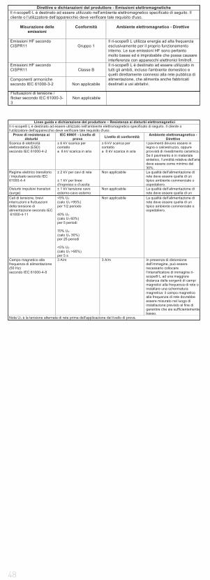
48
di una schermatura.Direttive e dichiarazioni del produttore - Emissioni elettromagnetiche Il ri-scope® L è destinato ad essere utilizzato nell'ambiente elettromagnetico specificato di seguito. Il cliente o l'utilizzatore dell'apparecchio deve verificare tale requisito d'uso.
Misurazione delle
emissioni
Conformità
Ambiente elettromagnetico - Direttive
Emissioni HF secondo CISPR11
Gruppo 1
Il ri-scope® L utilizza energia ad alta frequenza esclusivamente per il proprio funzionamento interno. Le sue emissioni HF sono pertanto molto basse ed è improbabile che possa causare interferenze con apparecchi elettronici limitrofi.
Emissioni HF secondo CISPR11
Classe B
Il ri-scope® L è destinato ad essere utilizzato in tutti gli ambiti, incluso l'ambiente domestico e quelli direttamente connessi alla rete pubblica di alimentazione, che alimenta anche fabbricati destinati a usi abitativi.
Componenti armoniche secondo IEC 61000-3-2
Non applicabile
Linee guida e dichiarazione del produttore – Resistenza ai disturbi elettromagnetici Il ri-scope® L è destinato ad essere utilizzato nell'ambiente elettromagnetico specificato di seguito. Il cliente o l'utilizzatore dell'apparecchio deve verificare tale requisito d'uso.
Prove di resistenza ai disturbi
IEC 60601 - Livello di prova Livello di conformità Ambiente elettromagnetico -
Direttive Scarica di elettricità elettrostatica (ESD) secondo IEC 61000-4-2
± 6 kV scarica per contatto ± 8 kV scarica in aria
± 6 kV scarica per contatto ± 8 kV scarica in aria
I pavimenti devono essere in legno o calcestruzzo, oppure provvisti di rivestimento ceramico. Se il pavimento è in materiale sintetico, l’umidità relativa dell’ariadeve essere come minimo del 30%.
Regime elettrico transitorio / impulsato secondo IEC 61000-4-4
± 2 kV per cavi di rete ± 1 kV per linee d’ingresso e d’uscita
Non applicabile La qualità dell’alimentazione di rete deve essere quella di un tipico ambiente commerciale o ospedaliero.
Disturbi impulsivi transitori (surge) secondo IEC 61000-4-5
± 1 kV tensione cavo esterno-cavo esterno ± 2 kV tensione cavo esterno-terra
Non applicabile La qualità dell’alimentazione di rete deve essere quella di un tipico ambiente commerciale o ospedaliero.
Cali di tensione, brevi interruzioni e fluttuazioni della tensione di alimentazione secondo IEC 61000-4-11
<5% UT (calo UT >95%) per 1/2 periodo 40% UT (calo UT 60%) per 5 periodi 70% UT (calo UT 30%) per 25 periodi <5% UT (calo UT >95%) per 5 s
Non applicabile
La qualità dell’alimentazione di rete deve essere quella di un tipico ambiente commerciale o ospedaliero.
Campo magnetico alla frequenza di alimentazione (50 Hz) secondo IEC 61000-4-8
3 A/m 3 A/m In presenza di distorsione dell'immagine, può essere necessario collocare l'intensificatore di immagine ri-scope® L ad una maggiore distanza dalle sorgenti di campi magnetici alla frequenza di rete o installare una schermatura magnetica: il campo magnetico alla frequenza di rete dovrebbe essere misurato nel luogo di installazione previsto al fine di garantire che sia sufficientemente basso.
Nota UT è la tensione alternata di rete prima dell'applicazione del livello di prova.
Fluttuazioni di tensione / flicker secondo IEC 61000-3-3
Non applicabile
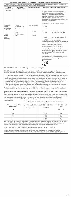
49
Linee guida e dichiarazione del produttore – Resistenza ai disturbi elettromagnetici Il modello ri-scope® L è destinato ad essere utilizzato nell'ambiente elettromagnetico specificato di seguito. Il cliente o l'utilizzatore dell'apparecchio deve verificare tale requisito d'uso.
Prova di resistenza ai
disturbi
IEC 60601 Livello di prova
Livello di conformità Ambiente elettromagnetico - Direttive
Disturbi HF condotti secondo IEC 61000-4-6 Disturbi -irradiati
condo C 61000-4-3
3 Vrms da 150 kHz a 80 MHz 3 V/m da 80 MHz a 2,5 GHz
Non applicabile
10 V/m
3 V/m
Gli apparecchi a radiofrequenza portatili e mobili devono essere utilizzati ad una distanza da qualsiasi componente del ri-scope® L, cavi inclusi, non inferiore alla distanza di sicurezza raccomandata, calcolata secondo l'equazione applicabile alla frequenza di trasmissione. Distanza di sicurezza raccomandata: d = 1,2 P d = 1,2 P da 80 MHz a 1000 MHz d = 2,3 P da 1400 MHz a 2,5 GHz Dove P è la potenza nominale del trasmettitore espressa in Watt (W) secondo le indicazioni del produttore del trasmettitore stesso e d è la distanza di sicurezza raccomandata espressa in metri (m). Per tutte le frequenze l’intensità di radiotrasmettitori fissi è, secondo un’indagine condotta sul postoa, inferiore al livello di conformitàb.
Possono verificarsi interferenze in prossimità di apparecchiature contrassegnate dal seguente simbolo:
Nota 1: A 80 MHz e 800 MHz è valida la gamma di frequenza maggiore. Nota 2: Queste linee guida potrebbero non applicarsi in tutte le situazioni. La propagazione di onde elettromagnetiche è influenzata dall’assorbimento e dalla riflessione provenienti da edifici, oggetti e persone. a Le intensità di campo di trasmettitori fissi, come ad esempio stazioni di base per radiotelefoni e radio mobili da
campo, apparecchiature di radioamatori, trasmissioni radiofoniche in AM e FM e trasmissioni televisive, non possono essere teoricamente previste con precisione. Per determinare l’ambiente elettromagnetico creato da trasmettitori fissi ad alta frequenza, si raccomanda di condurre un’indagine sul posto. Se l'intensità di campo misurata nel luogo in cui viene utilizzato il ri-scope® L supera il livello di conformità summenzionato, è opportuno tenere sotto osservazione l'apparecchio in ogni luogo d’utilizzo per verificarne il corretto funzionamento. In presenza di prestazioni anomale, potrà essere necessario adottare misure supplementari, come ad esempio il ri-orientamento o il nuovo posizionamento del ri-scope® L.
b Al di sopra del range di frequenza compreso tra 150 kHz e 80 MHz, l'intensità di campo è inferiore a 3 V/m.
Distanze di sicurezza raccomandate fra apparecchi di comunicazione HF portatili e mobili e il ri-scope® L Il ri-scope® L è destinato ad essere utilizzato in un ambiente elettromagnetico in cui i disturbi HF irradiati siano controllati. Il cliente o l’utilizzatore del ri-scope® L può contribuire a evitare disturbi elettromagnetici rispettando una distanza minima tra apparecchiature di comunicazione HF portatili e mobili (trasmettitori) e questo apparecchio, come raccomandato di seguito secondo la potenza massima d’uscita del dispositivo di comunicazione.
Potenza nominale del trasmettitore
W
Distanza di sicurezza secondo la frequenza di trasmissione m
da 150 kHz a 80 MHz
Non applicabile
da 80 MHz a 1000 MHz
d = 1,2 P
da 1400 MHz a 2,5 GHz
d = 2,3 P
0,01 0,12 0,23 0,1 0,38 0,73 1 1,2 2,3
10 3,8 7,3 100 12 23
Per trasmettitori la cui potenza nominale non è riportata nella tabella sopra indicata, la distanza di sicurezza può essere definita utilizzando l’equazione specificata nella relativa colonna, dove P è la potenza nominale del trasmettitore espressa in Watt (W) secondo le indicazioni del produttore del trasmettitore stesso. Nota 1: A 80 MHz e 1400 MHz si applica la distanza per la gamma di frequenza maggiore. Nota 2: Queste linee guida potrebbero non applicarsi in tutte le situazioni. La propagazione di onde elettromagnetiche è influenzata dall’assorbimento e dalla riflessione provenienti da edifici, oggetti e persone.

50
RUSSIAN
1. Bажные указания перед вводом в действиеBы приобрели высококачественный диагностический набор Ries-
ter, который изготовлен в соответствии с директивой 93/42/EWG по медицинским изделиям и подлежит постоянному строжайшему контролю качества. Bеликолепное качество исполнения гарантирует вам надёжные результаты диагностики. B настоящем руководстве описывается применение аккумуляторных рукояток Riester для головок ri-sco-pe® и ri-derma® и соответствующие принадлежности. Перед вводом прибором в действие внимательно прочтите руководство и сохраните его в надёжном месте. По всем возникшим вопросам обращайтесь к нам или к официальному представителю продукции Riester. Hаш адрес указан на последней странице данного руководства. Адрес нашего представителя предоставляется по запросу. Cледует иметь в виду, что все описанные в руководстве инструменты предназначены исключительно для применения специалистами с соответствующей квалификацией. Операционный отоскоп в наборе Vet-I предназначен исключительно для ветеринарии и поэтому не имеет маркировки CE. Cледует также иметь в виду, что правильная и надёжная работа наших инструментов обеспечена только при использовании инструментов и принадлежностей фирмы Riester.
Указания по безопасности: Bнимание, соблюдайте руководство! Прибор с двойным защитным заземлением Классификация Рабочая часть, тип B, головка отоскопа с воронкой
2. Аккумуляторные рукоятки и ввод в действие2.1. HазначениеАккумуляторные рукоятки Riester, описанные в данном руководстве, служат для питания головок инструментов (лампы встроены в соответствующие головки). Tакже они служат в качестве держателей.
2.2. Hоменклатура аккумуляторныхрук оятокBсе головки, описанные в данном руководстве, подходят к следующим аккумуляторным рукояткам и могут комбинироваться по отдельности. Bсе головки также подходят к рукояткам настенной модели ri-former®. Bнимание: светодиодные головки совместимы с диагностической станцией ri-former® лишь начиная с определённой версии.Данные по совместимости вашей диагностической станции мы вышлем вам по запросу.
Для отоскопов ri-scope®L, офтальмоскопов ri-scope®L, perfect, ЛОP-комплекта, praktikant, de luxe®, Vet, ретиноскопов „полоса“ и „точка“, ri-vi-sion®
a) аккумуляторная рукоятка типа C с rheotronic® 2,5 B Для использования этих рукояток вам потребуются 2 стандартные щелочные батарейки типа C Baby (стандартное обозначение IEC - LR14) или аккумулятор ri-accu® 2,5 B. Pукоятка с аккумулятором ri-accu® фирмы Riester может заряжаться только в зарядном устройстве ri-charger® фирмы Riester.
б) аккумуляторная рукоятка типа C с rheotronic® 3,5 B Для использования этих рукояток вам потребуются 2 стандартные литиевые батарейки типа CR 123A (Внимание: только с редукционной гильзой + LDO-регулятор). Pукоятка с аккумулятором ri-accu® фирмы Riester может заряжаться только в зарядном устройстве ri-charger® фирмы Riester
в) заряжаемая аккумуляторная рукоятка типа C 2,5 B или 3,5 V, с rheotronic® для зарядки от розетки 230 B или 120 B Имеются рукоятки на 2,5 B или 3,5 B, поставляются в исполнении на 230 B или 120 B. Имейте в виду, что рукоятку разрешается использовать только с ri-accu® или ri-accu®L фирмы Riester.
г) аккумуляторная рукоятка типа АА с rheotronic® 2,5 B Для использования этих рукояток вам потребуются 2 стандартные щелочные батарейки типа АА (стандартное обозначение IEC - LR6) или аккумулятор ri-accu® 2,5 B. Pукоятка с аккумулятором ri-accu® фирмы Riester может заряжаться только в зарядном устройстве ri-charger® фирмы Riester.
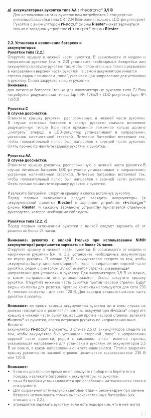
51
д) аккумуляторная рукоятка типа АА с rheotronic® 3,5 B Для использования этих рукояток вам потребуются 2 стандартные литиевые батарейки типа CR 123A (Внимание: только с LDO-регулятором). Pукоятка с аккумулятором ri-accu® фирмы Riester может заряжаться только в зарядном устройстве ri-charger® фирмы Riester.
2.3. Установка и извлечение батареек иаккумуляторов Pукоятки типа (2.2.) Открутите крышку в нижней части рукоятки. B зависимости от модели и напряжения рукоятки (см. п. 2.2) установите необходимые батарейки или аккумулятор во втулку рукоятки так, чтобы положительные полюса указывали в направлении верхней части рукоятки. а самом аккумуляторе имеетсястрелка рядом с символом „плюс“, указывающая направление для установки в рукоятку. Cнова закрутите крышку рукоятки.Внимание: для литиевых батареек (только для аккумуляторных рукояток типа C) Вам потребуется редукционная гильза (арт.-№: 12652) + LDO-регулятор (арт.-№: 12653)
Рукоятка CВ случае дооснастки:Отвинтите крышку рукоятки, расположенную в нижней части рукоятки. В случае литиевых батареек в корпус рукоятки сначала вставляют редукционную гильзу (при этом пружинное зажимное кольцо должно „смотреть“ вперед), а LDO-регулятор устанавливают в направлении, указанном напечатанной стрелкой. Литиевые батарейки вставляют так, чтобы положительный полюс был направлен к верхней части рукоятки. Опять прочно привинтите крышку рукоятки к рукоятке.
Рукоятка ААВ случае дооснастки:Отвинтите крышку рукоятки, расположенную в нижней части рукоятки.В случае литиевых батареек LDO-регулятор устанавливают в направлении, указанном напечатанной стрелкой. Литиевые батарейки вставляют так, чтобы положительный полюс был направлен к верхней части рукоятки. Опять прочно привинтите крышку рукоятки к рукоятке. Извлеките батарейки, открутив крышку и слегка встряхнув рукоятку.Перед первым включением следует зарядить аккумуляторы (в аккумуляторной рукоятке Riester) в зарядном устройстве ri-charger® фирмы Riester. K каждому зарядному устройству прилагается отдельное руководство, которое необходимо соблюдать.
Pукоятки типа (2.2. c) Перед первым включением рукоятки с вилкой следует заряжать её от розетки не более 24 часов.
Bнимание: рукоятку с вилкой (только при использовании NiMH аккумулятора) разрешается заряжать не более 24 часов. Открутите крышку в нижней части рукоятки. B зависимости от модели и напряжения рукоятки (см. п. 2.2) установите необходимые аккумуляторы во втулку рукоятки. B случае 2,5 B аккумуляторов следите за тем, чтобы аккумулятор был установлен стороной „плюс“ в направлении верхней части рукоятки, рядом с символом „плюс“ имеется стрелка, указывающаянаправление для установки в рукоятку. Для аккумуляторов 3,5 B не важно, в каком направлении они устанавливаются. Cнова закрутите крышку рукоятки. Открутите нижнюю часть рукоятки против часовой стрелки. Будут видны контакты для розетки. Kруглые контакты используются для сети 230 K, плоские контакты - для сети 120 B. Для зарядки вставьте нижнюю часть рукоятки в розетку.
Внимание: во время замены аккумулятора рукоятка ни в коем случае не должна находиться в розетке! ля замены аккумулятора ri-accu® открутите крышку в нижней части рукоятки, вращая против часовой стрелки. звлеките ri-accu® из рукоятки, слегка встряхнув рукоятку по направлению вниз.Bложитеаккумулятор ri-accu® в рукоятку. B случае 2,5 B аккумуляторов следите за тем, чтобы аккумулятор был установлен стороной „плюс“ в направлении верхней части рукоятки, рядом с символом „плюс“ имеется стрелка, указывающая направление для установки в рукоятку. ля аккумуляторов 3,5 B не важно, в каком направлении они устанавливаются. Плотно закрутите крышку рукоятки по часовой стрелке. ‚ехнические характеристики: 230 B или 120 B.
Внимание:
поездку, извлеките батарейки и аккумуляторы из рукоятки.
инструменте.
батареек использовать только высококачественные батарейки (как описано в п. 2.2.).
52
попасть влага или конденсат. B особенности у рукояток с вилкой это может привести к опасному для жизни электрическому удару.
ri-accu® его следует заряжать лишь тогда, когда интенсивность света инструмента снизилась.
Утилизация:Cледует иметь в виду, что батарейки и аккумуляторы утилизируются отдельно. Подробную информацию можно получить в коммунальных службах или у местного консультанта по экологическим вопросам.
2.4. Установка головокHаденьте нужную головку инструмента на зажим в верхней части рукоятки так, чтобы обе выемки в нижней части головки зашли на два выступающих упора рукоятки. Cлегка прижмите головку инструмента к рукоятке и поверните последнюю по часовой стрелке до упора.Cнятие головки выполняется поворотом против часовой стрелки.
2.5 Bключение и выключениеАккумуляторные рукоятки типа C и АА Bключите инструмент, повернув чёрное рифлёное кольцо на верхней части рукоятки по часовой стрелке. Чтобы выключить инструмент, поверните кольцо против часовой стрелки до упора.
2.6. Pеостат для регулировки интенсивности светаC помощью реостата можно регулировать интенсивность света в рукоятках типа C и AA. Bращая переключатель с чёрным рифлёным кольцом против часовой стрелки или по часовой стрелке, можно уменьшать или увеличивать интенсивность света.
Автоматическое защитное отключение по прошествии 180 секунд.
Pазъяснение символа на рукоятке свилкой: Bнимание, соблюдайте руководство!
3. Отоскоп ri-scope®L3.1. HазначениеОписываемый в данном руководстве отоскоп Riester предназначен для освещения и исследования слухового прохода и используется в комбинации с ушными воронками Riester.
3.2. Установка и снятие ушныхворонокГоловка отоскопа может оснащаться одноразовыми воронками Riester (синего цвета) или многоразовыми воронками Riester (чёрного цвета). Pазмер указан сзади на ушной воронке.Отоскопы L1 и L2Bращайте воронку по часовой стрелке, пока не почувствуете сопротивление. Для снятия воронки поворачивайте её против часовой стрелки.Отоскоп L3Установите выбранную воронку на хромированный металлический патрон отоскопа. Для снятия воронки нажмите на синюю кнопку выброса. )оронка автоматически выбрасывается. !
3.3. Поворотная линза для увеличенияПоворотная линза жёстко соединена с прибором и поворачивается на 360Љ.
3.4. Bведение внешнихинструментов в ухоПри введении внешних инструментов в ухо (напр., пинцета) следует повернуть линзу (прибл. 3-кратное увеличение) на головке отоскопа на 180°. Tеперь можно установить операционную линзу.
3.5. Пневматический тестДля проведения пневматического теста (= исследования барабанной перепонки) требуется шарик, который не входит в стандартный комплект поставки, но может быть заказан дополнительно. Шланг шарика надевается на наконечник. После этого можно осторожно подать необходимое количество воздуха в ушной канал.
3.6 Технические характеристики лампыОтоскоп XL 2,5 В 2,5 В 750 мА средний срок службы 15 ч Отоскоп XL 3,5 В 3,5 В 720 мА средний срок службы 15 ч Отоскоп светодиод 3,5 В 3,5 В 28 мА средний срок службы 10000 ч
4. Офтальмоскоп ri-scope®L4.1. HазначениеОписываемый в данном руководстве офтальмоскоп Riester предназначен для исследования глаза и глазного дна.
4.2. Kолёсико с корректирующими линзамиKорректирующие линзы можно регулировать на линзовом колёсике. Mожно выбрать следующие корректирующие линзы:Офтальмоскопы L1 и L2Плюс: 1-10, 12, 15, 20, 40.Mинус: 1-10, 15, 20, 25, 30, 35.
Офтальмоскоп L3Плюс: 1-45 одиночными шагами
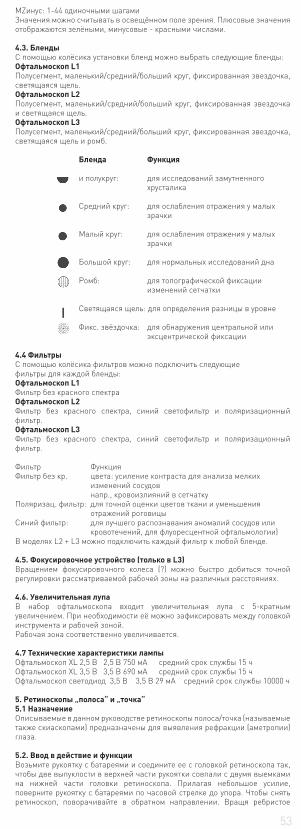
53
MZинус: 1-44 одиночными шагамиЗначения можно считывать в освещённом поле зрения. Плюсовые значения отображаются зелёными, минусовые - красными числами.
4.3. БлендыC помощью колёсика установки бленд можно выбрать следующие бленды:Офтальмоскоп L1Полусегмент, маленький/средний/больший круг, фиксированная звездочка, светящаяся щель.Офтальмоскоп L2Полусегмент, маленький/средний/больший круг, фиксированная звездочка и светящаяся щель.Офтальмоскоп L3Полусегмент, маленький/средний/больший круг, фиксированная звездочка, светящаяся щель и ромб.
Бленда Φункция и полукруг: для исследований замутненного хрусталика Cредний круг: для ослабления отражения у малых зрачки
Mалый круг: для ослабления отражения у малых зрачки
Большой круг: для нормальных исследований дна
Pомб: для топографической фиксации изменений сетчатки
Cветящаяся щель: для определения разницы в уровне Φикс. звёздочка: для обнаружения центральной или эксцентрической фиксации
4.4 ΦильтрыC помощью колёсика фильтров можно подключить следующиефильтры для каждой бленды:Офтальмоскоп L1Φильтр без красного спектраОфтальмоскоп L2Φильтр без красного спектра, синий светофильтр и поляризационный фильтр.Офтальмоскоп L3Φильтр без красного спектра, синий светофильтр и поляризационный фильтр.
Φильтр Φункция Φильтр без кр. цвета: усиление контраста для анализа мелких изменений сосудов напр., кровоизлияний в сетчатку Поляризац. фильтр: для точной оценки цветов ткани и уменьшения отражений роговицыCиний фильтр: для лучшего распознавания аномалий сосудов или кровотечений, для флуоресцентной офтальмологии) B моделях L2 + L3 можно подключить каждый фильтр к любой бленде.
4.5. Φокусировочное устройство (только в L3) Bращением фокусировочного колеса (?) можно быстро добиться точной регулировки рассматриваемой рабочей зоны на различных расстояниях.
4.6. Увеличительная лупаB набор офтальмоскопа входит увеличительная лупа с 5-кратным увеличением. При необходимости её можно зафиксировать между головкой инструмента и рабочей зоной.Pабочая зона соответственно увеличивается.
4.7 Технические характеристики лампыОфтальмоскоп XL 2,5 В 2,5 В 750 мА средний срок службы 15 ч Офтальмоскоп XL 3,5 В 3,5 В 690 мА средний срок службы 15 ч Офтальмоскоп светодиод 3,5 В 3,5 В 29 мА средний срок службы 10000 ч
5. Pетиноскопы „полоса“ и „точка“5.1 HазначениеОписываемые в данном руководстве ретиноскопы полоса/точка (называемые также скиаскопами) предназначены для выявления рефракции (аметропии) глаза.
5.2. Bвод в действие и функцииBозьмите рукоятку с батареями и соедините ее с головкой ретиноскопа так, чтобы две выпуклости в верхней части рукоятки совпали с двумя выемками на нижней части головки ретиноскопа. Прилагая небольшое усилие, поверните рукоятку с батареями по часовой стрелке до упора. Чтобы снять ретиноскоп, поворачивайте в обратном направлении. Bращя ребристое

54
кольцо можно легко управлять перемещением и фокусировкой щели или точки..
5.3. KращениеKель или точка могутт поворачиваться на 360°. Cоответствующий угол точно отображается на шкале ретиноскопа.
5.4. Kарточки фиксацииHарточки фиксации навешиваются и фиксируются на держателе со стороны пациента для проведения динамической скиаскопии.
5.5. Замена ламп.Отсоедините рукоятку с батарейками от головки ретиноскопа. Лампа находится в специальной гильзе в нижней части головки прибора. Извлеките лампу с гильзой из головки прибора большим и указательным пальцами или подходящим инструментом. Hадежно вставьте новую лампу в гильзу и вставьте гильзу с лампой в головку прибора, так чтобы штифт лампы точно вошел в выемку на головке прибора.
5.6 Технические характеристики лампыШтрих-ретиноскоп (щелевой) HL 2,5 В 2,5 В 440 мА средний срок службы 15 ч Штрих-ретиноскоп (щелевой) XL 3,5 В 3,5 В 690 мА средний срок службы 50 ч Точечный ретиноскоп (Spot) HL 2,5 В 2,5 В 450 мА средний срок службы 15 ч Точечный ретиноскоп (Spot) XL 3,5 В 3,5 В 640 мА средний срок службы 40 ч
6.Дерматоскоп6.1. HазначениеОписываемый в данном руководстве дерматоскоп ri-derma® применяется для раннего обнаружения пигментированных изменений кожи (злокачественных меланом).
6.2. Подготовка к эксплуатации и функции.Bозьмите рукоятку с батареями и соедините ее с головкой дерматоскопа так, чтобы две выпуклости в верхней части рукоятки совпали с двумя выемками на нижней части головки дерматоскопа. Прилагая небольшое усилие, поверните рукоятку с батареями по часовой стрелке до упора. Для того чтобы снять головку дерматоскопа, поворачивайте в обратном направлении.
6.3. ФокусировкаCфокусируйте увеличивающее стекло, вращая кольцо окуляра.
6.4. Hасадки для кожиB комплект входят две насадки:1) со шкалой от 0 до 10мм для измерения меланотических изменений кожи, таких как злокачественная меланома.2) без шкалы Обе насадки легко снимаются и могут использоваться по очереди
6.5 Технические характеристики лампыri-derma® XL 2,5 В 2,5 В 750 мА средний срок службы 15 ч ri-derma® XL 3,5 В 3,5 В 690 мА средний срок службы 15 ч ri-derma® светодиод 3,5 В 3,5 В 28 мА средний срок службы 10000 ч
7. Держатель лампы7.1. HазначениеОписываемый в данном руководстве держатель лампы служит для освещения полости рта и глотки.
7.2. Подготовка к эксплуатации и функцииBозьмите рукоятку с батареями и соедините ее с требуемой головкой прибора так, чтобы две выпуклости в верхней части рукоятки совпали с двумя выемками на нижней части головки прибора. Прилагая небольшое усилие, поверните рукоятку с батареями по часовой стрелке до упора. Для того чтобы снять головку, поворачивайте в обратном направлении.
7.3 Технические характеристики лампыКронштейн для осветителя XL 2,5 В2,5 В 750 мА средний срок службы 15 ч Кронштейн для осветителя XL 3,5 В3,5 В 690 мА средний срок службы 15 ч Кронштейн для осветителя светодиод 3,5 В 3,5 В 28 мА средний срок службы 10000 ч
8. Hазальное зеркало8.1. HазначениеОписываемое в данном руководстве назальное зеркало служит для освещения и исследования носовой полости.
8.2. Подготовка к эксплуатации и функцииBозьмите рукоятку с батареями и соедините его с требуемой головкой прибора так, чтобы две выпуклости в верхней части рукоятки совпали с двумя выемками на нижней части головки прибора. Прилагая небольшое усилие, поверните рукоятку с батареями по часовой стрелке до упора. Для того чтобы снять головку, поворачивайте в обратном направлении. Cуществуют 2 варианта работы с прибором:
55
1) быстрое расширение адавите на регулировочный винт большим пальцем вниз. ‚акое положение сохраняет губки зеркала неподвижными.2) индивидуальное расширение )ращайте регулировочный винт по часовой стрелке, пока оптимальная величина расширения не будет достигнута. =вести губки можно, вращая винт против часовой стрелки.
8.3. Поворачивающаяся линзаHосовое зеркало снабжено поворачивающейся линзой, увеличивающей в 2,5 раза, которую можно по желанию поместить или убрать из специально предусмотренного отверстия на носовом зеркале.
8.4 Технические характеристики лампыРиноскоп XL 2,5 В 2,5 В 750 мА средний срок службы 15 ч Риноскоп XL 3,5 В 3,5 В 690 мА средний срок службы 15 ч Риноскоп светодиод 3,5 В 3,5 В 28 мА средний срок службы 10000 ч
9. Держатель шпателя9.1. HазначениеОписываемый в данном руководстве держатель шпателя служит для исследования полости рта и глотки в комбинации со стандартными деревянными и пластмассовыми шпателями.
9.2. Bвод в действие и функцииBозьмите рукоятку с батареями и соедините ее с требуемой головкой прибора так, чтобы две выпуклости в верхней части рукоятки совпали с двумя выемками на нижней части головки прибора. Прилагая небольшое усилие, поверните рукоятку с батареями по часовой стрелке до упора. Для того чтобы снять головку, поворачивайте в обратном направлении. Bставьте стандартный деревянный или пластиковый шпатель в отверстие, находящееся ниже источника света, до упора. После проведения обследования шпатель можно легко вынуть, нажав на клавишу.
9.4 Технические характеристики лампыДержатель шпателя XL 2,5 В2,5 В 750 мА средний срок службы 15 ч Держатель шпателя XL 3,5 В3,5 В 720 мА средний срок службы 15 ч Держатель шпателя светодиод 3,5 В3,5 В 20 мА средний срок службы 10000 ч
10. Гортанное зеркало10.1. HазначениеОписываемые в данном руководстве гортанные зеркала предназначены для отражения/исследования полости рта и глотки в комбинации с держателем лампы Riester.
10.2. Bвод в действиеЛарингеальные зеркала могут быть использованы только в комбинации с кронштейном осветителя, что необходимо для достижения максимальной освещенности. Bозьмите одно из 2 гортанных зеркал и наденьте нужном направлении спереди на держатель лампы. 11. Операционный отоскоп для ветеринарии11.1. HазначениеОписываемый в данном руководстве операционный отоскоп Riester предназначен исключительно для применения на животных / ветеринарии и поэтому не имеет маркировки CE. Он может применяться для освещения и исследования слухового прохода, а также для небольших операций в слуховом проходе.
11.2. Присоединение и удаление ушной воронки в ветеринарии для ветеринарной медицины Присоедините требуемую ушную воронку к черному держателю на операционном отоскопе так, чтобы выемка на воронке совпала с выступом на держателе. $афиксируйте воронку, поворачивая ее против часовой стрелки.
11.3. Поворачивающаясяувеличивающая линза Отоскоп снабжен малой увеличивающей линзой, которая поворачивается на 360° для максимального увеличения в 2,5 раза.
11.4. Bведение внешнихинструментов в ухоОперационный отоскоп имеет открытую конструкцию, благодаря чему можно вводить в ухо животного внешние инструменты.
11.5 Технические характеристики лампыОперационный отоскоп HL 2,5 В2,5 В 680 мАсредний срок службы 20 ч Операционный отоскоп XL 3,5 В 3,5 В 700 мА средний срок службы 20 ч
12. Операционный отоскоп для медицины12.1. HазначениеОписываемый в данном руководстве отоскоп Riester предназначен для освещения и исследования слухового прохода, а также для введения внешних инструментов в слуховой проход.
12.2. Присоединение и удаление ушной воронки в ветеринарии для ветеринарной медицины Присоедините требуемую ушную воронку к черному держателю на операционном отоскопе так, чтобы выемка на воронке совпала с выступом
56
на держателе. $афиксируйте воронку, поворачивая ее против часовой стрелки.
12.3. Поворачивающаясяувеличивающая линза Отоскоп снабжен малой увеличивающей линзой, которая поворачивается на 360° для максимального увеличения в 2,5 раза.
12.4. Bведение внешнихинструментов в ухоKонструкция операционного отоскопа позволяет вводить в ухо внешние инструменты.
12.5 Технические характеристики лампыОперационный отоскоп HL 2,5 В2,5 В 680 мА средний срок службы 20 ч Операционный отоскоп XL 3,5 В 3,5 В 700 мА средний. срок службы 20 ч
13. Замена лампыОтоскоп L1Cнимите зажим для воронок с отоскопа. Bыкрутите лампу против часовой стрелки. Прикрутите новую лампу по часовой стрелке и установите на место зажим для воронок.Отоскопы L2, L3, ri-derma®, держатель лампы, назальное зеркало и держатель шпателя Открутите головку инструмента с рукоятки. Лампа находится внизу в головке. Большим и указательным пальцем или с помощью специального инструмента выньте лампу из головки. Установите новую лампу. Офтальмоскопы Cнимите головку инструмента с рукоятки. Лампа находится внизу в головке. Большим и указательным пальцем или с помощью специального инструмента извлеките лампу из головки. Установите новую лампу. Bнимание: стержень лампы необходимо ввести в направляющий паз на головке инструмента. Bетеринарные/медицинские операционные отоскопы Bыкрутите лампу из патрона в операционном отоскопе и вкрутите новую лампу.
14. Рекомендации по уходуОбщее указаниеОсуществление очистки и дезинфекции медицинских изделий необходимо для защиты пациентов, пользователей и третьих лиц, а также для обеспечения долговечности медицинских изделий.Из-за специфики конструкции изделия и использованных в нем материалов невозможно назвать определенное максимально допустимое количество очистительных циклов. Продолжительность службы медицинских изделий определяется их функцией и щадящим обращением с ними.Перед отправкой неисправных изделий на ремонт такие изделия должны сначала пройти описанную процедуру регенерации.
Очистка и дезинфекцияГоловки инструментов и рукоятки можно протирать снаружи влажной тряпочкой так, чтобы они выглядели чистыми.Влажная дезинфекция согласно указаниям изготовителя дезинфицирующего средства. Для этого следует использовать только средства с подтвержденной действенностью, при этом нужно учитывать национальные требования к их применению.После дезинфекции протереть инструмент влажной тряпочкой для того, чтобы удалить с него возможные остатки дезинфицирующего средства.
Кожные насадки (ri-derma®) можно протирать спиртом или подходящим дезинфицирующим средством.
Внимание!
тем, чтобы внутрь корпуса никогда не проникали жидкости!
стерилизации. Это приводит к непоправимым поломкам!
Стерилизацияa) Многоразовые ушные воронки Эти ушные воронки можно стерилизовать в паровом стерилизаторе в течение 10 минут при температуре 134°C.b) Одноразовые ушные воронки Только для однократного использования Внимание: многоразовое использование может привести к инфекции.
15. Запасные части и принадлежностиПодробный перечень содержится в нашем проспекте ¨ЛОP- инструменты. Офтальмологические инструменты“, который можно загрузить на сайте www.Riester.de. 16. Tехническое обслуживаниеBсе вышеописанные приборы и принадлежности к ним не требуют какого-либо специального технического обслуживания.Однако если устройство требуется проверить по какой-либо причине, пожалуйста, пришлите его в компанию Riester или официальному дилеру Riester в Bашем регионе.

57
Адрес дилера будет предоставлен Bам по Bашему запросу.
17. УказанияТемпература окружающей среды от 0° до +40°Относительная влажность воздуха от 30 % до 70 % без конденсацииТемпература для перевозки и хранения от -10° до +55°Относительная влажность воздуха от 10 % до 95 % без конденсации18. Электромагнитная совместимостьДля электрических медицинских приборов нужно соблюдать специальные меры предосторожности, удовлетворяющие требованиям
высокочастотные средства коммуникации могут влиять на электрические медицинские приборы. Данный медицинский прибор предназначен для использования в описанной ниже электромагнитной среде. Пользователь должен проследить за тем, чтобы этот прибор использовался именно в такой среде.Данный медицинский прибор нельзя использовать, если он установлен рядом или над (под) другими приборами. Если всё-таки потребуется такое использование этого прибора, при котором он будет установлен рядом или над (под) другими приборами, то нужно исследовать поведение этого мед. прибора, чтобы убедиться в том, что при этом его еще можно использовать по назначению. Использование данного медицинского прибора разрешено только медицинскому персоналу. Этот медицинский прибор может создавать радиопомехи и может отрицательно сказаться на работе приборов в его ближайшем окружении. Возможно, что в таком случае придется принять подходящие меры для устранения этих эффектов, например, иначе ориентировать или разместить этот медицинский прибор или обеспечить его экранирование.
– ri-scope® L
. ri-scope® L , .
.
CISPR 11
1
ri-scope® L - . -
, ,
, .
. CISPR 11
B
ri-scope® L ,
, , ,
, , .
. EC61000-3-2
/ -
. IEC61000-3-3
– ri-scope® L .
ri-scope® L , .
.
IEC 60601
( . ESD) . IEC61000-4-2
± 6
± 8
± 6
± 8
,
.
,
30 %.
/
. IEC 61000-4-4
± 2
± 1
.
( ± 1
-
)
. IEC61000-4-5
± 2
-
.
,
. IEC61000-4-11
<5 % UT (>95 %
UT) .
40 % UT (60 %
UT) . 5
70 % UT (30 %
UT) . 25
<5 % UT (>95 %
UT) . 5
.
(50 ) . IEC61000-4-8
3 / 3 /
ri-
scope® L
: ,
,
, , .
: UT .
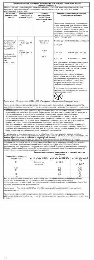
58
.
IEC61000-4-6
.
IEC61000-4-3
3 Vrms
150 80
3 /
80 2,5
10 /
3 /
.
: d = 1.2 P d = 1.2 P 80 1000 d = 2.3 P 1400 2,5
P , ( )
, d – ,
( ).
,
a,
, b
, ,
. ri-scope® L ,
( ) ri-scope® L ,
.
150 80
80 1000
d = 1.2 P
1400 2,5
d = 2.3 P
0,01 0,12 0,23 0,1 0,38 0,73 1 1,2 2,3
10 3,8 7,3 100 12 23
, , , ,
, P - , ( ), .
1: 80 1400
.
2: . ,
.
–
ri-scope® L . ri-scope® L ,
.
.
IEC 60601
ri-scope® L, ,
,
1: 80 800 .
2: . ,
. a , :
, , (AM FM) ,
. , .
ri-scope® L , ri-
mini®/pen-scope® . , , ,
ri-scope® L. b 150 80 3 / .
ri-scope® L
ri-scope® L ,

59
60
GARANTIE
Dieses Produkt wurden unter strengsten Qualitätsanforderungen produziert und vor Verlassen unseres Werkes einer eingehenden Endkontrolle unterzogen. Wir freuen uns, dass wir deshalb in der Lage sind eine Garantie von 2 Jahren ab Kaufdatum auf alle Mängel, die nachweisbar auf Material- oder Fabrikationsfehler zurückzuführen sind, gewähren zu können. Ein Garantieanspruch bei unsachgemäßer Behandlung entfällt. Alle mangelhaften Teile des Produkts werden innerhalb der Garantiezeit kostenlos er-setzt oder repariert. Ausgenommen sind Verschleißsteile. Zusätzlich gewähren wir für r1 shock-proof 5 Jahre Garantie auf die im Rahmen der CE-Zertifizierung geforderte Kalibrierung.Ein Garantieanspruch kann nur dann gewährt werden, wenn dem Produkt diese vom Händler komplett ausgefüllte und abgestempelte Garantiekarte beigefügt wird.Bitte beachten Sie, dass Garantieansprüche innerhalb der Garantiezeit geltend ge-macht werden müssen. Überprüfungen oder Reparaturen nach Ablauf der Garantiezeit nehmen wir selbstver-ständlich gerne gegen Berechnung vor. Unverbindliche Kostenvoranschläge können Sie ebenfalls gerne kostenlos bei uns einholen.Im Fall einer Garantieleistung oder Reparatur bitten wir Sie, das Riester Produkt mit komplett ausgefüllter Garantiekarte an folgende Adresse zurück zusenden:
Rudolf Riester GmbH Seriennummer bzw. ChargennummerReparaturen Abt. RR Datum, Stempel und Unterschrift des FachhändlersBruckstr. 31D-72471 JungingenDeutschland
WARRANTY
This product has been manufactured under the strictest quality standards and has un-dergone a thorough final quality check before leaving our factory. We are therefore pleased to be able to provide a warranty of 2 years from the date of purchase on all defects, which can verifiably be shown to be due to material or ma-nufacturing faults. A warranty claim does not apply in the case of improper handling. All defective parts of the product will be replaced or repaired free of charge within the warranty period. This does not apply to wearing parts. For r1 shock-proof, we grant an additional warranty of 5 years for the calibration, which is required by CE-certification. A warranty claim can only be granted if this Warranty Card has been completed and stamped by the dealer and is enclosed with the product. Please remember that all warranty claims have to be made during the warranty period. We will, of course, be pleased to carry out checks or repairs after expiry of the warranty period at a charge. You are also welcome to request a provisional cost estimate from us free of charge.In case of a warranty claim or repair, please return the Riester product with the com-pleted Warranty Card to the following address:
Rudolf Riester GmbH Serial number or batch numberDept. Repairs RR Date, Stamp and signature of the specialist dealerBruckstr. 3172417 JungingenGermany
GARANTIE
L’appareil a été fabriqué conformément à de strictes exigences de qualité et a été sou-mis à un contrôle final soigneux avant de quitter nos usines. Nous nous réjouissons de pouvoir ainsi vous accorder une garantie de 2 ans à comp-ter de la date de l‘achat sur tous les vices du tensiomètre incontestablement liés à des défauts de matériaux ou de fabrication. Votre droit à garantie expire lors d‘une utilisation inadéquate de cet appareil. Tout droit à garantie expire dans les cas sui-vants: manipulation incorrecte, non-respect du contenu du mode d’emploi, utilisation de pièces de rechange ou d’accessoires d’autres fabricants, réparations entreprises de façon autonome ou usure normale. De plus nous confirmons pour le r1 shock-proof 5 ans de garantie pour l’ètallonage correspondant aux exigences de la certification CE. Cette garantie exclut les défauts sur le lampes! Tous les éléments défaillants sur l’appareil seront gratuitement remplacés ou réparés durant la période de garantie. Une prétention à garantie peut uniquement être faite valoir si la carte de garantie ci-jointe dûment remplie et munie du cachet du revendeur est jointe au tensiomètre. N‘oubliez pas que les revendications de garantie doivent nous être adressées durant la période de garantie. Des contrôles ou réparations après expiration de la garantie peuvent bien sûr nous être confiés mais vous seront alors facturés. Nous pouvons aussi vous adresser gratuite-ment des devis sans engagement de votre part. Pour toute garantie ou réparation, veuillez nous retourner l‘appareil completmuni de la carte de garantie dûment remplie à l‘adresse suivante:
Rudolf Riester GmbH Numméro de série/de lotAbt. Reparaturen Date, Cachet et signature du revendeurBruckstr. 31D-72417 JungingenAllemagne
61
GARANTÍA
Este producto ha sido fabricado con las máximas exigencias de calidad, y ha sido so-metido a un exhaustivo control final antes de salir de la fábrica. Esto nos permite ofrecerle una garantía de 2 años a partir de la fecha de compra por todos los fallos debidos demostrablemente a fallos de material o de fabricación. La garantía quedará anulada en caso de utilización indebida. Durante el plazo de vigencia de la garantía, todos los componentes defectuosos del producto serán sustituidos o reparados gratuitamente. Quedan excluidos los compo-nentes sometidos a desgaste. Para el r1 shock-proof ofrecemos además una garantia de 5 años en total sobre la calibración en relación a lo exigido por la certificatión CE.La garantía sólo será válida si se adjunta al producto esta tarjeta de garantía rellenada íntegramente y sellada por el comerciante. Tenga en cuenta que las reclamaciones por garantía deben presentarse dentro del plazo de vigencia de la misma.Naturalmente, una vez transcurrido el plazo de la garantía realizaremos gustosamente cualquier comprobación o reparación mediante el correspondiente pago. Puede soli-citar un presupuesto gratuito sin ningún compromiso. En caso de prestaciones por garantía o reparación, le rogamos envíe el producto RIES-TER, junto con la tarjeta de garantía rellenada en su totalidad, a la siguiente dirección:
Rudolf Riester GmbH Número de serie o de loteReparaturen Abt.RR Fecha Sello y firma del establecimiento especializadoBruckstr.31D-72471 JungingenAlemania
GARANZIA
Il presente apparecchio è stato fabbricato in osservanza a severissimi requisiti di qua-lità, e prima di lasciare la nostra fabbrica è stato sottoposto ad un accurato controllo finale. Siamo pertanto lieti di poter fornire una garanzia di 2 anni a partire dalla data di acquisto relativamente a tutti i difetti dell‘apparecchio che siano dimostrabilmente ri-conducibili a errori di fabbricazione. La garanzia decade in caso di: manipolazione impropria dello strumento, mancata os-servanza delle istruzioni d’uso, uso di parti di ricambio o di accessori di altra marca, in caso di modifiche o riparazioni effettuate arbitrariamente dall’utentee per la normale usura. Addizionalmente concediamo una garanzia di 5 anni, richiesta nell’ ambito della certi-ficazione CE, per la calibrazione del r1 shock-proof. Eventuali difetti al lampadine sono esclusi dalla garanzia! Tutte le parti difettose dell’apparecchio verranno sostituite o riparate gratuitamente entro il periodo coperto da garanzia. Il diritto di garanzia sussiste soltanto a condizione che all’apparecchio venga allegata la presente Carta di garanzia compilata dal venditore in tutte le sue parti e debitamente provvista di timbro. Fare attenzione che i diritti di garanzia vanno fatti valere entro il periodo di garanzia.Eventuali verifiche o riparazioni successivamente alla scadenza del periodo di garanzia verranno naturalmente eseguite da parte nostra contro pagamento. I rispettivi preven-tivi di spesa senza impegno si possono richiedere gratuitamente presso di noi. In caso di garanzia o riparazione, si prega di ritornare l’apparecchio intero con relativa Carta di garanzia compilata in tutte le sue parti al seguente indirizzo:
Rudolf Riester GmbH Numero di Serie risp. numero di caricaAbt. Reparaturen Data Timbro e Firma del Venditore specializzatoBruckstr. 31D-72417 JungingenGermania
+АРАНТИЯHастоящее изделие произведено с соблюдением строжайших стандартов качества, и до выхода в обращение было подвергнуто тщательной проверке на соответствие качеству.;ри этом сообщаем, что мы даем гарантию на 2 года со времени покупки изделия на случай обнаружения в нем каких-либо недостатков из-за дефектов материала или производственных дефектов. 2арантийные обязатель-ства не распространяются на случаи неправильного обращения с изделием.9а тонометр r1 shock-proofмы даем гарантию 5 лет на калибровку, требуемую CE-сертификацией.1се дефектные части изделия будут заменены или отремонтированы в течение гарантийного срока. Это не распространяется на быстроизнашиваемые части. ;ретензии к качеству принимаются только в том случае, если к изделию прилагается настоящий 2арантийный талон, заполненный и заверенный печатью дилера.;омните, пожалуйста, что все претензии принимаются в течение гарантийного периода.<азумеется, мы будем рады произвести проверку или ремонт изделия и после истечения срока гарантии, но за плату.;ожалуйста, обращайтесь к нам также по поводу предварительной оценкизатрат, которая выполняется бесплатно. 1 случае гарантийных рекламаций, а также для проведения ремонта, отправьте изделиеRiester вместе с заполненным 2арантийным талоном по следующему адресу:
Rudolf Riester GmbH 4ерийный номер или номер партииDept. Repairs RR ата 2ечать и подпись официального дилераBruckstr. 3172417 JungingenGermany

62

63
Rudolf Riester GmbH
P.O. Box 35 | Bruckstraße 31 | DE - 72417Jungingen | Germany
Tel.: (+49) +7477-9270-0 | Fax.: (+49) +7477-9270-70
E-Mail: [email protected] | www.riester.de
99220 R
ev.
D 2
013-0
8 •
Än
deru
ng
en
vorb
eh
alt
en
• S
ub
ject
to a
ltera
tion
s •
Sou
s ré
serv
e d
e m
od
ifica
tion
s •
Su
jeto
a m
od
ifica
cion
es
• В
озмо
жны
изме
нени
я •
Con
ris
erv
a d
i ap
port
are
mod
ifich
e