
QUALITA’ E SERVIZIO AL CLIENTE PRIMA DI TUTTO. · A partire da tale data, negli Stati membri...
55
Transcript of QUALITA’ E SERVIZIO AL CLIENTE PRIMA DI TUTTO. · A partire da tale data, negli Stati membri...

3
QUALITA’ E SERVIZIO AL CLIENTE PRIMA DI TUTTO.
GMC Refrigerazione è un’azienda giovane e dinamica presente nel settore della refrigerazione e del condizionamento dal 2002 fondata su una solida base storica di professionalità e di lunga esperienza. In breve tempo GMC si è affermata ed è cresciuta rapidamente, dedicandosi con passione alle esigenze del mercato, proponendo prodotti di altissima qualità, grazie a sistematici ad efficaci processi di collaudo interno sul 100% della produzione, puntando alla completa soddisfazione del cliente. Le nuove idee e i nuovi progetti danno vita ad un ambiente di lavoro all’avanguardia nel rispetto dell’ambiente, gestito da personale competente che si propone di consolidare il marchio GMC e di distribuire i propri prodotti sul mercato nazionale ed internazionale acquistando sempre più visibilità ed instaurando le basi per una continua e costante crescita nel futuro.Il nostro focus? Qualità e Servizio. GMC ha conservato lo stesso spirito, lo stesso movente per il quale ha intrapreso la propria attività: credere fermamente che esiste “un altro modo” per essere un buon partner di lavoro in un sistema economico moderno, il cui mercato è in continua evoluzione. “l’altro modo” è quello di offrire qualità, flessibilità e servizio al cliente nel modo più efficace possibile. Come un ingranaggio di un perfetto meccanismo d’orologio, GMC ambisce ad essere parte efficiente di una catena di trasmissione i cui partner, siano essi clienti o fornitori, costituiscano un sistema economico virtuoso, auto-trainante in cui si trasformino le novità in opportunità di sviluppo economico vantaggioso per tutti.E’ per questo che GMC, da sempre attenta alle necessità dei propri clienti, opera da anni con sistema di qualità certificato ISO 9001:2008, si è dotata delle ultime tecnologie di collaudo ad Elio delle tenute e si impegna costantemente e non con pochi sforzi, ad aggiornarsi ed adeguare i propri prodotti alle nuove Direttive e ai Regolamenti comunitari.
Proprio in materia di sicurezza ambientale e risparmio energetico, GMC propone la nuova gamma di prodotti destinati ai fluidi refrigeranti a basso impatto ambientale HFO e per sistemi che utilizzano refrigeranti naturali: idrocarburi HC e anidride carbonica R744 che oggi completano il nostro catalogo…...il nostro catalogo, la risposta in stile GMC alle vostre necessità.
FIRST OF ALL QUALITY AND CUSTOMER CARE
GMC Refrigerazione is a young and dynamic company, founded on a solid base of professionalism and with a long background, active in Refrigeration and air-conditioning market since 2002.GMC achieved a rapid grow-up by offering high quality and 100% tested products thanks to the perfect internal process, focusing on customer satisfaction and market request.Innovation, the new ideas and new projects create a perfect workplace, managed by expert personnel which try to consolidate GMC brand by distribution the products in national and international market, earning more visibility and creating bases for continues and constant development in future.Our Mission? Quality and Service. GMC has maintained the same spirit, the same motive for Which began its activities: believing definitely that exists “another way” for being a good job cooperator in a modern economical system, in which the market is in continuous evolution. “Another way” is offering quality, flexibility and customer care in the best possible way. Like a perfect gear watch mechanism, GMC try to be effective part of chain transmission between partners that are customers and suppliers, creating a virtual economical system, moving by itself that transform novelty in opportunity for economic development with benefits for all parts.That’s why GMC, always care about customer request, working since so many years with Quality Certified System ISO9001:2008, is equipped with last test technology by Helium and try always, not easily, to adopt proper products to new Directive and European Regulations.Exactly about the environment safety and energy saving, GMC offer new range of products for applying with lower environmental effect HFO and for the systems which apply natural refrigerants: Hydrocarbons HC and Carbon dioxide R744 that today complete our catalogue……our catalogue is GMC style reply to your necessity.

4 5
PURCHASE ORDERSCustomer confirms “General Sales Conditions” of GMC Refrigerazione S.r.l. and not commit us to the customer’s purchase conditions.SHIPMENTThe goods travel at the risk of the customer in all cases, including “EX WORKS”DELIVERYThe delivery terms are indicative and not mandatory, any delay shall not cause costs, liability or penalty for GMC Refrigerazione S.r.l.. COMPLAINTSAny complaints are valid if submitted at our office within and not later than 15 days of receipt of goods.WARRENTYOur products are guaranteed for a period of 12 months. The warranty applies to all products that have defects within the warranty period, in which case the customer, at his own expense, must return the product together with a detailed description of the claimed defects; The guarantee will not apply if the defect of the products turn out to be mistakes of the customer or third parties, incorrect installation, tampering or use of these products differently from the instructions enclosed with the GMC Refrigerazione S.r.l. products. For any defects in products, GMC Refrigerazione S.r.l., is committed to replace them without recognizing any right caused by damages.RETURNSWe accept returns, only after release written authorization of GMC Refrigerazione S.r.l.DISPUTESFor any disagree or legal problem, the Court of Milan is the sole competent.
For specific applications in different conditions from those in the data sheets of our products we are advised to contact the technical department of GMC Refrigerazione S.r.l.
STANDARDS AND DIRECTIVES APPLIED ON PRODUCTSFrom July 19th 2016 will enter into force fully renewed Directive 2014/68/EU PED (known also as PED2) that substitute Directive 97/23/CE, to complete the gradual change started on 1st June 2015, the date which Article 13 of Directive 2014/68/EU PED, on the classification of pressure equipment, has repealed the Article 9 of the previous PED.
From that date only EC marked pressure equipment according to Directive 2014/68/EU PED can be marketed in the Member States of European Community and the declaration of conformity shall be written according to Annex IV.Article 2 of new Directive 2014/68/EU PED, define, in the same way as Article 1 of previous directive, following terms:• Pressure equipment: vessels, piping, safety accessories, and pressure accessories.• Vessel: a container designed and built to keep fluids under pressure.• Piping: piping components intended for the transport of fluids, when connected together to form a pressure system.• Safety accessories: devices designed to protect pressure equipment from exceeding the admissible limits.• Pressure accessories: devices with an operational function and including pressure bearing containers. For example: solenoid valves, valves, indicators.• Assemblies: several pieces of pressure equipment assembled by a manufacturer to constitute an integrated and functional set.• Maximum admissible pressure (PS): the maximum pressure the equipment is designed for, as specified by the manufacturer.• Maximum/minimum allowable temperature (TS): the maximum/minimum temperatures the equipment is designed for, as specified by the manufacturer.• Volume (V): the internal volume of a chamber, including the volume of nozzles to the first connection or weld and excluding the volume of permanent inner parts.• Nominal size (DN): numerical designation of size, which is common to all components in a piping system.• Fluids: gases, liquids and vapours in pure form as well as mixes thereof.
Pressure equipments referred to in Article 4 and in the Annex II to Directive 2014/68/EU PED are classified by categories according to ascending level of hazard, on the basis of:• State of the fluid• Hazard classification of the fluid• Type of equipment• Dimensions and energetic potential: DN, PS, V, PS x V, PS x DNand must comply with the Essential Safety Requirements as set out in Annex I of the same
ORDINI DI ACQUISTOGli ordini presuppongono da parte del cliente l’accettazione delle condizioni di vendita GMC REFRIGERAZIONE S.r.l non vincolandoci alle condizioni di acquisto del cliente.SPEDIZIONILe merci viaggiano a rischio del cliente anche in caso di “franco fabbrica”.CONSEGNAI termini di consegna sono indicativi e non impegnativi, quindi eventuali ritardi non danno diritto a nessuna richiesta di addebito, di responsabilità o penalità.RECLAMISi intendono validi eventuali reclami se inoltrati presso la nostra sede entro 15 giorni dal ricevimento della merce.GARANZIAI nostri prodotti sono garantiti per un periodo di 12 mesi. La garanzia riguarda tutti i prodotti che dovessero risultare difettosi entro il periodo di garanzia, in tal caso il cliente, a sue spese, deve restituire i prodotti unitamente a una descrizione dettagliata dei difetti riscontrati; la garanzia non è riconosciuta quando i difetti dei prodotti dovessero risultare errori del cliente o di terzi, per installazioni errate, manomissioni o utilizzo di tali prodotti in modo diverso dalle istruzioni allegate ai prodotti GMC Refrigerazione S.r.l. Per eventuali difetti dei prodotti, GMC Refrigerazione S.r.l, si impegna alla sostituzione degli stessi senza riconoscere diritti di risarcimento danni di qualsiasi specie.RESISi accettano resi di merce solo se autorizzati da GMC Refrigerazione S.r.l e solo se in porto franco.CONTROVERSIEIn caso di vertenza si riconosce unico competente il Foro di Milano.
Per applicazioni specifiche in condizioni differenti da quelle riportate nelle schede tecniche dei nostri prodotti si consiglia di contattare l’ufficio tecnico di GMC Refrigerazione S.r.l.
ASPETTI NORMATIVI E DIRETTIVE COGENTI SUI PRODOTTIDal 19 Luglio 2016 entrerà in vigore integralmente la rinnovata Direttiva 2014/68/EU PED, (conosciuta anche come PED2 o PED Recast) che abroga la precedente Direttiva 97/23/CE, completando così il graduale cambiamento iniziato il 1°giugno 2015, data in cui l’articolo 13 della Direttiva 2014/68/EU PED, relativo alla classificazione delle attrezzature a pressione, ha abrogato l’Articolo 9 della precedente Direttiva PED.A partire da tale data, negli Stati membri della Comunità Europea, diverrà obbligatoria la commercializzazione unicamente di attrezzature a pressione marcate CE, secondo la Direttiva 2014/68/EU PED e la cui dichiarazione di conformità dovrà essere redatta in conformità all’Allegato IV.L’Articolo 2 della rinnovata Direttiva 2014/68/EU PED, sancisce, analogamente all’Articolo 1 della precedente Direttiva 97/23/CE, le seguenti definizioni:• Attrezzature a pressione: recipienti, tubazioni, accessori di sicurezza e accessori a pressione.• Recipiente: un alloggiamento progettato e costruito per contenere fluidi in pressione.• Tubazioni: i componenti di una conduttura destinati al trasporto di fluidi, allorché essi sono collegati al fine di essere inseriti in un sistema a pressione.• Accessori di sicurezza: i dispositivi destinati alla protezione degli apparecchi a pressione contro il superamento dei limiti ammissibili.• Accessori a pressione: dispositivi aventi funzione di servizio e i cui alloggiamenti sono sottoposti a pressione; ad esempio: valvole solenoidi, rubinetti in genere, indicatori.• Insiemi: varie attrezzature a pressione assemblate da un costruttore per costituire un tutto integrato e funzionante.• Pressione massima ammissibile (PS): la pressione massima per la quale l’attrezzatura è progettata, specificata del costruttore.• Temperatura minima / massima ammissibile (TS): le temperature minima / massima per le quali l’attrezzatura è progettata, specificate dal costruttore.• Volume (V): il volume interno di una camera compreso il volume dei raccordi alla prima connessione ed escluso il volume degli elementi interni permanenti.• Dimensione nominale (DN): la designazione numerica della dimensione che è comune a tutti i componenti di un sistema di tubazioni• Fluidi: i gas, i liquidi e i vapori allo stato puro e le loro miscele.
Nell’Articolo 4 e nell’Allegato II della Direttiva 2014/68/EU PED le attrezzature a pressione sono classificate in categorie di rischio crescente dalla I alla IV in funzione di:• Stato del fluido contenuto• Classe di pericolosità del fluido contenuto• Tipo di attrezzatura
CONDIZIONI DI VENDITA
INFORMAZIONI GENERALI SUIPRODOTTI
SALES CONDITION
GENERAL PRODUCTSINFORMATION
• Dimensioni e potenziale energetico: DN, PS, V, PS x V, PS x DNe devono soddisfare i Requisiti Essenziali di Sicurezza stabiliti nell’Allegato I della Direttiva stessa. Tali attrezzature sono indicate nel catalogo con il numero della categoria di appartenenza (Es.: Cat.I) Le attrezzature a pressione aventi caratteristiche inferiori o pari ai limiti fissati ai punti 1.a, 1.b e 1.c e al punto 2 dell’Articolo 4 della Direttiva 2014/68/EU PED non devono soddisfare i Requisiti Essenziali di Sicurezza stabiliti nell’Allegato I, ma devono essere progettati e fabbricati secondo una corretta prassi costruttiva in uso in uno degli Stati membri che assicuri la sicurezza di utilizzazione; tali attrezzature non devono recare la marcatura CE (Articolo 4, Paragrafo 3). Tali attrezzature sono indicate nel catalogo con la dicitura Art. 4.3.
Nell’Articolo 13 della Direttiva 2014/68/EU PED i fluidi sono classificati, in base alla loro pericolosità, in due gruppi:• Gruppo 1 che comprende sostanze e miscele, così come definite all’articolo 2, punti 7 e 8, del regolamento CE n. 1272/2008, classificate come pericolose a norma delle classi di pericolo fisico e per la salute di cui all’Allegato I, parti 2 e 3 di tale Regolamento. Al punto 1.a dell’Articolo 13 sono elencate 18 classi di fluidi pericolosi (esplosivi, infiammabili, comburenti, tossici).• Gruppo 2 che comprende sostanze e miscele non elencate al punto 1.aL’immissione nel mercato di nuovi refrigeranti per effetto dell’applicazione del Regolamento F-Gas disposto per il contenimento e la riduzione delle quantità di idrofluorocarburi commerciabile, ha indotto GMC Refrigerazione ad attente verifiche di compatibilità dei propri prodotti finora utilizzati con i refrigeranti HFC tradizionali. L’esito positivo di tali verifiche e gli adeguamenti apportati consentono a GMC Refrigerazione di rendere disponibili i propri prodotti anche per i seguenti nuovi fluidi:- HFC monocomponenti tipo R32 (1).- HFO monocomponenti tipo R1234yf (1) e R1234ze.- Miscele HFC/HFO tipo R448A, R449A, R450A, R452A, R513A.Nota (1): Per applicazioni con questi fluidi (classificati A2L secondo ASHRAE 34-2013) fare riferimento alla sezione prodotti HC (fluidi di Gruppo 1).
Nel paragrafo “Ambito di applicazione” di questo catalogo, vi è indicato per quali fluidi refrigeranti è impiegabile ogni prodotto GMC; sarà quindi possibile trovare i seguenti impieghi:- con fluidi refrigeranti appartenenti al Gruppo 2, così come definiti nell’Articolo 13, paragrafo 1, lettera b, della Direttiva PED e classificati A1 nell’Annex E della norma EN 378-1; fra questi fluidi sono presenti anche R22, R134a, R404A, R407C, R410A, R507, R513A.- con fluidi refrigeranti appartenenti al Gruppo 1 , classificati A2L nell’Annex E della norma EN 378-1:2008. I suddetti fluidi sono: R32 , R1234yf, R1234ze.- con fluidi refrigeranti appartenenti al Gruppo 1, classificati A3 nell’Annex E della norma EN 378-1:2008; fra questi fluidi sono presenti l’ R290, R600, R600a.TENUTA VERSO L’ESTERNOTutti i prodotti GMC Refrigerazione sono testati in produzione singolarmente con le modalità e i requisiti indicati dalle seguenti Norme specifiche di prodotto:EN 12178 – Impianti di refrigerazione e pompe di calore - Indicatori del livello del liquido - Requisiti, prove e marcaturaEN 12284 – Impianti di refrigerazione e pompe di calore - Valvole – Requisiti, prove, marcaturaEN 14276-1 – Attrezzature a pressione per sistemi di refrigerazione e pompe di calore Parte1: Recipienti – Requisiti generaliEN ISO 14903: 2017 – Impianti di refrigerazione e pompe di calore - Procedura di qualifica delle tenute dei componenti e dei giunti.RESISTENZA A PRESSIONETutti i prodotti GMC sottoposti a prova idrostatica garantiscono una resistenza pari ad almeno 1,43 x PS come previsto dalla Direttiva PED 2014/68/EU. La resistenza alla prova di scoppio, viene effettuata su base statistica durante la produzione annuale: per i prodotti HFC/HFO e R744 subcritico il valore di accettabilità è pari ad almeno 3 x PS come previsto dalla norma EN 378-2; per i prodotti R744 transcritico il valore di accettabilità è pari ad almeno 2,5 x PS. Molti dei prodotti GMC superano abbondantemente tali valori.TOLLERANZE DIMENSIONALII prodotti assemblati mediante accoppiamenti saldati, possono avere tolleranza di ±2 mm sulla lunghezza totale “L”.DESCRIZIONE DEI COLLEGAMENTISAE Flare: Attacco filettato (secondo SAE J513-92; ASME B1.1-89) per collegamento con tubo di rame idoneamente svasato a cartella e in combinazione con un adatto bocchettone.NPT: Attacco filettato con filettatura conica secondo ASME B1.20.1-92.ODS (oppure ODF): Attacco a brasare femmina per tubo di rame, le dimensioni si riferiscono al diametro esterno del tubo di rame a cui effetturae il collegamento.ODM (Attacco in rame): Attacco a brasare maschio per tubo di rame, le dimensioni si riferiscono al diametro esterno del tubo di rame a cui effetturae il collegamento.ODM (Attacco in acciaio): Attacco a saldare per turbi in acciaio, le dimensioni si riferiscono al diametro esterno del tubi in acciaio a cui effettuare il collegamento mediante saldatura elettrica di testa.IDS: Attacco a brasare maschio per tubo di rame, le dimensioni si riferiscono al diametro interno del tubo di rame a cui effetturae il collegamento.
Directive. These equipments are shown in the catalog with the number of the category they belong (Ex .: Cat.I).Pressure equipment whose characteristics are below or equal to the limits in Article 4, points 1.a, 1.b and 1.c and section 2 of Directive PED Recast must not comply with the Essential Safety Requirements as set out in Annex I, but must be designed and manufactured in accordance with the sound engineering practice in a Member State in order to guarantee safe use; these products needn’t bear EC marking (Article 4,Paragraph 3). These equipments are shown in the catalog as Art. 4.3.
In Article 13 of Directive 2014/68/EU PED, fluids are classified, according to level of their hazard, in two groups:• Group 1 includes substances and mixtures, as defined in points 7 and 8 of Article 2 of EC Regulation No 1272/2008, that are classified as hazardous in accordance with physical or health hazard classes as laid down in Parts 2 and 3 of Annex I to thatRegulation. A list of 18 classes of hazardous fluids is included in point 1.a of Article 13 (explosive, flammable, oxidizing, toxic).• Group 2 includes substances and mixtures not listed on point 1.aThe reduction of the quantity of hydrofluorocarbons released on the market due to F-Gas regulation and the introduction of new refrigerants with a lower environmental impact has inspired GMC Refrigerazione to carefully check the compatibility of its products so far used with traditional HFC refrigerants. The successful results of these tests and the adjustments made allow GMC Refrigerazione to make its products available also for the following new fluids:- monocomponents HFCs type R32 (1).- monocomponets HFO type R1234yf (1) and R1234ze.- HFC/HFO mixtures type R448A, R449A, R450A, R452A, R513A.Note (1): For applications with these fluids (classified A2L according to ASHRAE 34-2013) refer to the HC products section (Group 1 fluids).
In the paragraph “Application” of this catalog, it is indicated for which refrigerants can be used each product GMC; you can then find the following applications:- suitable for use with fluids proper to the Group 2, as defined in Article 13, paragraph 1, letter b, of Directive PED 2014/68/EU, and Group belongs also the refrigerant fluids listed and classified in A1 Group of Annex E of standard EN 378-1 among these fluids are present R22, R134a, R404A, R407C, R410A, R507, R513A.- with refrigerant fluids belonging to Group 1, classified A2L Annex E of standard EN 378-1. These fluids are: R32, R1234yf, R1234ze.- With refrigerant fluids belonging to Group 1, classified A3 in Annex E of standard EN 378-1: 2008; among these fluids are present the R290, R600, R600a.EXTERNAL LEAKAGEAll GMC Refrigeration products are individually tested in accordance with the procedures and requirements indicated by the following Product Specific Standards:EN 12178 – Refrigerating systems and heat pumps Liquid level indicating devices - Requirements, testing and markingEN 12284 – Refrigerating systems and heat pumps Valves - Requirements, testing and markingEN 14276-1 – Pressure equipment for refrigerating systems and heat pumps Part 1: Vessels – General requirementsEN ISO 14903: 2017 – Refrigerating systems and heat pumps Qualification of tightness of components and jointsSTRENGTH PRESSURE TESTAll GMC products submitted to hydrostatic test, guarantee a pressure strength at least equal to 1,43 x PS in compliance with the Directive PED 2014/68 /EU. The burst test, is statistically performed during the annual production: for the HFC / HFO and R744 subcritical products the acceptability value is equal to at least 3 x PS as provided by the EN 378-2 standard; for transcritical R744 products, the acceptability value is at least 2,5 x PS. Many GMC products guarantee greater resistance to these values.DIMENSIONAL TOLERANCESAll welded assembled products, could have ±2 mm tolerance of total length “L”.DESCRIPTION OF CONNECTIONSSAE Flare:Straight threaded connection (according to SAE J513-92; ASME B1.1-89) for junction to a copper pipe with a suitable flared end, using a right nut.NPT: Taper threaded connection (according to ASME B1.20.1-92).ODS (or ODF): Female solder connection for copper tubes; the indicated size corresponds to the outer diameter of the copper tube which to joint.ODM (for copper connections):Male solder connection for copper tubes; the indicated size corresponds to the external diameter of the copper tube which to joint.ODM (for steel connections):Solder connection for steel pipes; the indicated size corresponds to the external diameter of the steel pipe which make the connection in the electric welding head.IDS: Male solder connection for copper tube; the indicated size corresponds to the inner diameter of the copper tube which to joint.
6 7
ACCESSORI - ACCESSORIES
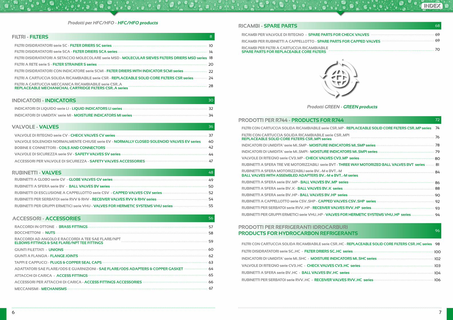
FILTRI - FILTERS
RICAMBI - SPARE PARTS
INDICATORI - INDICATORS
PRODOTTI PER R744 - PRODUCTS FOR R744
PRODOTTI PER REFRIGERANTI IDROCARBURIPRODUCTS FOR HYDROCARBON REFRIGERANTS
VALVOLE - VALVES
RUBINETTI - VALVES
RACCORDI IN OTTONE - BRASS FITTINGS
FILTRI DISIDRATATORI serie SC - FILTER DRIERS SC series
Prodotti per HFC/HFO - HFC/HFO products
Prodotti GREEN - GREEN products
RICAMBI PER VALVOLE DI RITEGNO - SPARE PARTS FOR CHECK VALVES
ATTACCHI DI CARICA - ACCESS FITTINGS
INDICATORI DI UMIDITA’ serie MI - MOISTURE INDICATORS MI series
FILTRI CON CARTUCCIA SOLIDA RICAMBIABILE serie CSR..MP - REPLACEABLE SOLID CORE FILTERS CSR..MP series
FILTRI CON CARTUCCIA SOLIDA RICAMBIABILE serie CSR..MPIREPLACEABLE SOLID CORE FILTERS CSR..MPI series
FILTRI CON CARTUCCIA SOLIDA RICAMBIABILE serie CSR..HC - REPLACEABLE SOLID CORE FILTERS CSR..HC series
VALVOLE DI RITEGNO serie CV - CHECK VALVES CV series
RUBINETTI A SFERA serie BV - BALL VALVES BV series
RUBINETTI PER GRUPPI ERMETICI serie VHU - VALVES FOR HERMETIC SYSTEMS VHU series
RUBINETTI PER SERBATOI serie RVV & RHV - RECEIVER VALVES RVV & RHV series
RUBINETTI A GLOBO serie GV - GLOBE VALVES GV series
RUBINETTI DI ESCLUSIONE A CAPPELLOTTO serie CSV - CAPPED VALVES CSV series
INDICATORI DI UMIDITA’ serie MI..SMP - MOISTURE INDICATORS MI..SMP series
INDICATORI DI UMIDITA’ serie MI..SHC - MOISTURE INDICATORS MI..SHC series
INDICATORI DI UMIDITA’ serie MI..SMPI - MOISTURE INDICATORS MI..SMPI series
VALVOLE DI RITEGNO serie CV3..MP - CHECK VALVES CV3..MP series
VALVOLE DI RITEGNO serie CV3..HC - CHECK VALVES CV3..HC series
RUBINETTI A SFERA TRE VIE MOTORIZZABILI serie BVT - THREE WAY MOTORIZED BALL VALVES BVT series
RUBINETTI A SFERA MOTORIZZABILI serie BV..-M e BVT..-M BALL VALVES WITH ASSEMBLED ADAPTERS BV..-M e BVT..-M series
RUBINETTI A SFERA serie BV..MP - BALL VALVES BV..MP series
FILTRI DISIDRATATORI serie SC..HC - FILTER DRIERS SC..HC series
RUBINETTI A SFERA serie BV..K - BALL VALVES BV..K series
RUBINETTI A SFERA serie BV..HC - BALL VALVES BV..HC series
RUBINETTI A SFERA serie BV..HP - BALL VALVES BV..HP series
RUBINETTI A CAPPELLOTTO serie CSV..SHP - CAPPED VALVES CSV..SHP series
RUBINETTI PER SERBATOI serie RVV..HP - RECEIVER VALVES RVV..HP series
RUBINETTI PER SERBATOI serie RVV..HC - RECEIVER VALVES RVV..HC series
RUBINETTI PER GRUPPI ERMETICI serie VHU..HP - VALVES FOR HERMETIC SYSTEMS VHU..HP series
VALVOLE DI SICUREZZA serie SV - SAFETY VALVES SV series
INDICATORI DI LIQUIDO serie LI - LIQUID INDICATORS LI series
RICAMBI PER RUBINETTI A CAPPELLOTTO - SPARE PARTS FOR CAPPED VALVES
RICAMBI PER FILTRI A CARTUCCIA RICAMBIABILESPARE PARTS FOR REPLACEABLE CORE FILTERS
VALVOLE SOLENOIDI NORMALMENTE CHIUSE serie EV - NORMALLY CLOSED SOLENOID VALVES EV series
BOCCHETTONI - NUTS
TAPPI E CAPPUCCI - PLUGS & COPPER SEAL CAPS
FILTRI DISIDRATATORI serie SCA - FILTER DRIERS SCA series
RACCORDI AD ANGOLO E RACCORDI A TEE SAE FLARE/NPTELBOWS FITTINGS & SAE FLARE/NPT TEE FITTINGS
FILTRI DISIDRATATORI A SETACCIO MOLECOLARE serie MSD - MOLECULAR SIEVES FILTERS DRIERS MSD series
GIUNTI A FLANGIA - FLANGE JOINTS
FILTRI DISIDRATATORI CON INDICATORE serie SCMI - FILTER DRIERS WITH INDICATOR SCMI series
ADATTATORI SAE FLARE/ODS E GUARNIZIONI - SAE FLARE/ODS ADAPTERS & COPPER GASKET
FILTRI A CARTUCCIA SOLIDA RICAMBIABILE serie CSR - REPLACEABLE SOLID CORE FILTERS CSR series
FILTRI A CARTUCCIA MECCANICA RICAMBIABILE serie CSR..AREPLACEABLE MECHANICHAL CARTRIDGE FILTERS CSR..A series
GIUNTI FILETTATI - UNIONS
FILTRI A RETE serie S - FILTER STRAINER S series
ACCESSORI PER ATTACCHI DI CARICA - ACCESS FITTINGS ACCESSORIES
MECCANISMI - MECHANISMS
BOBINE E CONNETTORI - COILS AND CONNECTORS
ACCESSORI PER VALVOLE DI SICUREZZA - SAFETY VALVES ACCESSORIES
10
8
14
18
20
22
24
28
30
32
34
36
37
40
42
44
47
48 84
86
88
90
92
93
94
96
98
100
102
103
104
106
49
50
52
54
55
56
57
58
59
60
62
63
64
65
66
67
69
69
70
72
68
74
76
78
79
80
81
INDEXINDEX
8 9
HFC/HFOHFC/HFO
FILTRI DISIDRATATORI
FILTRIFILTERS
FILTERS DRIERSserie SC - SCA - MSD SC - SCA - MSD series
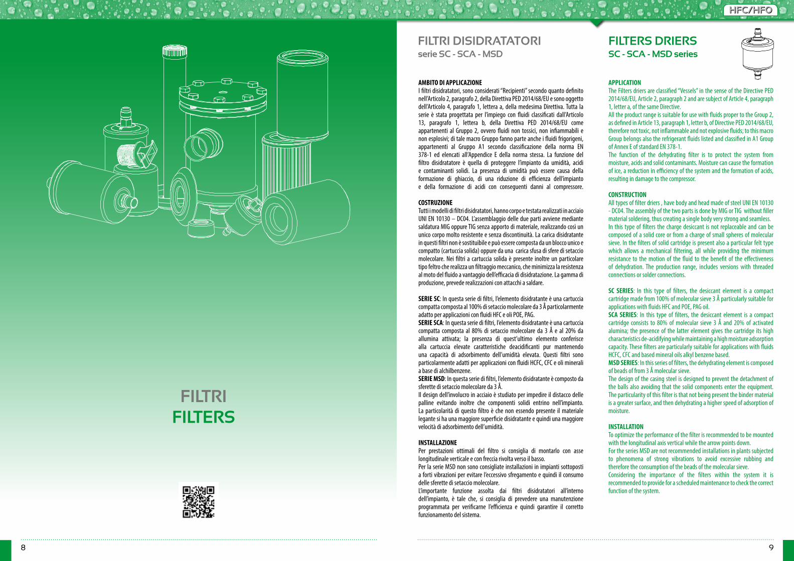
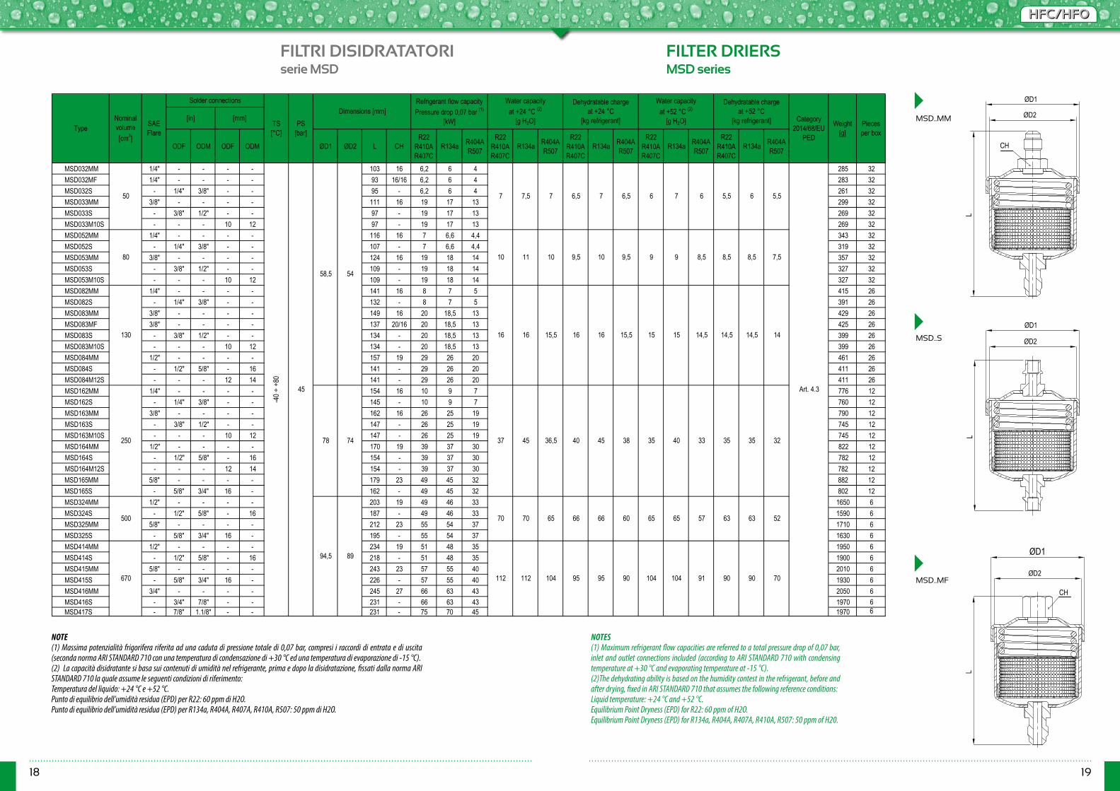
AMBITO DI APPLICAZIONEI filtri disidratatori, sono considerati “Recipienti” secondo quanto definito nell’Articolo 2, paragrafo 2, della Direttiva PED 2014/68/EU e sono oggetto dell’Articolo 4, paragrafo 1, lettera a, della medesima Direttiva. Tutta la serie è stata progettata per l’impiego con fluidi classificati dall’Articolo 13, paragrafo 1, lettera b, della Direttiva PED 2014/68/EU come appartenenti al Gruppo 2, ovvero fluidi non tossici, non infiammabili e non esplosivi; di tale macro Gruppo fanno parte anche i fluidi frigorigeni, appartenenti al Gruppo A1 secondo classificazione della norma EN 378-1 ed elencati all’Appendice E della norma stessa. La funzione del filtro disidratatore è quella di proteggere l’impianto da umidità, acidi e contaminanti solidi. La presenza di umidità può essere causa della formazione di ghiaccio, di una riduzione di efficienza dell’impianto e della formazione di acidi con conseguenti danni al compressore. COSTRUZIONETutti i modelli di filtri disidratatori, hanno corpo e testata realizzati in acciaio UNI EN 10130 – DC04. L’assemblaggio delle due parti avviene mediante saldatura MIG oppure TIG senza apporto di materiale, realizzando così un unico corpo molto resistente e senza discontinuità. La carica disidratante in questi filtri non è sostituibile e può essere composta da un blocco unico e compatto (cartuccia solida) oppure da una carica sfusa di sfere di setaccio molecolare. Nei filtri a cartuccia solida è presente inoltre un particolare tipo feltro che realizza un filtraggio meccanico, che minimizza la resistenza al moto del fluido a vantaggio dell’efficacia di disidratazione. La gamma di produzione, prevede realizzazioni con attacchi a saldare.
SERIE SC: In questa serie di filtri, l’elemento disidratante è una cartuccia compatta composta al 100% di setaccio molecolare da 3 Å particolarmente adatto per applicazioni con fluidi HFC e oli POE, PAG.SERIE SCA: In questa serie di filtri, l’elemento disidratante è una cartuccia compatta composta al 80% di setaccio molecolare da 3 Å e al 20% da allumina attivata; la presenza di quest’ultimo elemento conferisce alla cartuccia elevate caratteristiche deacidificanti pur mantenendo una capacità di adsorbimento dell’umidità elevata. Questi filtri sono particolarmente adatti per applicazioni con fluidi HCFC, CFC e oli minerali a base di alchilbenzene.SERIE MSD: In questa serie di filtri, l’elemento disidratante è composto da sferette di setaccio molecolare da 3 Å.Il design dell’involucro in acciaio è studiato per impedire il distacco delle palline evitando inoltre che componenti solidi entrino nell’impianto. La particolarità di questo filtro è che non essendo presente il materiale legante si ha una maggiore superficie disidratante e quindi una maggiore velocità di adsorbimento dell’umidità. INSTALLAZIONEPer prestazioni ottimali del filtro si consiglia di montarlo con asse longitudinale verticale e con freccia rivolta verso il basso.Per la serie MSD non sono consigliate installazioni in impianti sottoposti a forti vibrazioni per evitare l’eccessivo sfregamento e quindi il consumo delle sferette di setaccio molecolare.L’importante funzione assolta dai filtri disidratatori all’interno dell’impianto, è tale che, si consiglia di prevedere una manutenzione programmata per verificarne l’efficienza e quindi garantire il corretto funzionamento del sistema.
APPLICATIONThe Filters driers are classified “Vessels” in the sense of the Directive PED 2014/68/EU, Article 2, paragraph 2 and are subject of Article 4, paragraph 1, letter a, of the same Directive.All the product range is suitable for use with fluids proper to the Group 2, as defined in Article 13, paragraph 1, letter b, of Directive PED 2014/68/EU, therefore not toxic, not inflammable and not explosive fluids; to this macro Group belongs also the refrigerant fluids listed and classified in A1 Group of Annex E of standard EN 378-1.The function of the dehydrating filter is to protect the system from moisture, acids and solid contaminants. Moisture can cause the formation of ice, a reduction in efficiency of the system and the formation of acids, resulting in damage to the compressor. CONSTRUCTIONAll types of filter driers , have body and head made of steel UNI EN 10130 - DC04. The assembly of the two parts is done by MIG or TIG without filler material soldering, thus creating a single body very strong and seamless.In this type of filters the charge desiccant is not replaceable and can be composed of a solid core or from a charge of small spheres of molecular sieve. In the filters of solid cartridge is present also a particular felt type which allows a mechanical filtering, all while providing the minimum resistance to the motion of the fluid to the benefit of the effectiveness of dehydration. The production range, includes versions with threaded connections or solder connections.
SC SERIES: In this type of filters, the desiccant element is a compact cartridge made from 100% of molecular sieve 3 Å particularly suitable for applications with fluids HFC and POE, PAG oil.SCA SERIES: In this type of filters, the desiccant element is a compact cartridge consists to 80% of molecular sieve 3 Å and 20% of activated alumina; the presence of the latter element gives the cartridge its high characteristics de-acidifying while maintaining a high moisture adsorption capacity. These filters are particularly suitable for applications with fluids HCFC, CFC and based mineral oils alkyl benzene based.MSD SERIES: In this series of filters, the dehydrating element is composed of beads of from 3 Å molecular sieve.The design of the casing steel is designed to prevent the detachment of the balls also avoiding that the solid components enter the equipment. The particularity of this filter is that not being present the binder material is a greater surface, and then dehydrating a higher speed of adsorption of moisture.
INSTALLATIONTo optimize the performance of the filter is recommended to be mounted with the longitudinal axis vertical while the arrow points down.For the series MSD are not recommended installations in plants subjected to phenomena of strong vibrations to avoid excessive rubbing and therefore the consumption of the beads of the molecular sieve.Considering the importance of the filters within the system it is recommended to provide for a scheduled maintenance to check the correct function of the system.

10 11
HFC/HFOHFC/HFO
FILTRI DISIDRATATORI FILTER DRIERSserie SC..MM/MF SC..MM/MF series
SC..MF
SC..MM
ØD1 ØD2 L CHR22
R410A R407C
R134a R404A R507
R22 R410A R407C
R134a R404A R507
R22 R410A R407C
R134a R404A R507
R22 R410A R407C
R134a R404A R507
R22 R410A R407C
R134a R404A R507
SC032MM 1/4" - 103 16 10 8,5 7 285 32SC032MF 1/4" - 93 16/16 10 8,5 7 283 32SC033MM 3/8" - 111 16 19,5 17,5 13,5 299 32SC052MM 1/4" - 116 16 11 9 7,5 343 32SC053MM 3/8" - 124 16 23 21 16 357 32SC082MM 1/4" - 141 16 12 10,5 9 415 26SC083MM 3/8" - 149 16 27 25 17 429 26SC083MF 3/8" - 137 20/16 27 25 17 425 26SC084MM 1/2" - 157 19 36 33 23 461 26SC162MM 1/4" - 154 16 14 11 9,5 776 12SC163MM 3/8" - 162 16 31 29 20 790 12SC163ORFS - 6 152 19 31 29 20 810 12SC164MM 1/2" - 170 19 41 39 31 822 12SC164ORFS - 8 155 21 41 39 31 822 12SC165MM 5/8" - 179 23 54 50 35 882 12SC303ORFS - 6 237 19 49 47 39 1420 6SC304MM 1/2" - 247 19 50 48 40 1440 6SC304ORFS - 8 240 21 50 48 40 1440 6SC305MM 5/8" - 257 23 57 55 42 1460 6SC324MM 1/2" - 203 19 50 48 40 1650 6SC325MM 5/8" - 212 23 57 55 42 1710 6SC414MM 1/2" - 234 19 52 50 43 1950 6SC415MM 5/8" - 243 23 59 57 44 2010 6SC416MM 3/4" - 245 27 75 70 48 2050 6
6
93
56,2
500
Pieces per box
-40 ÷
+80
45
58,5
94,5
54
89
250
130
80
50
78 74
670
5,5 5
9 10 99 9,5 9
55,3
14
8 7,5 8 8
15 14,5 15,5
8
Art. 4.3
1315 14 14 13,5 14
7
4,56
90 80 84 100 84
Dehydratable charge at +24 °C
[kg refrigerant]
Water capacity at +52 °C (2)
[g H2O]
15,5
6 5
85 60
Water capacity at +24 °C (2)
[g H2O]
96 104 77
34
60
40
90
ORFS
Dehydratable charge at +52 °C
[kg refrigerant] Weight [g]
PS [bar]
Dimensions [mm]TS [°C]
Refrigerant flow capacity Pressure drop 0,07 bar (1)
[kW] Category 2014/68/EU
PED
5365
33
58
37
TypeNominal volume [cm3]
SAE Flare
15
6
33,5 30 3142 35 31,5
60 50
32 28
63 63 58 52 56 48
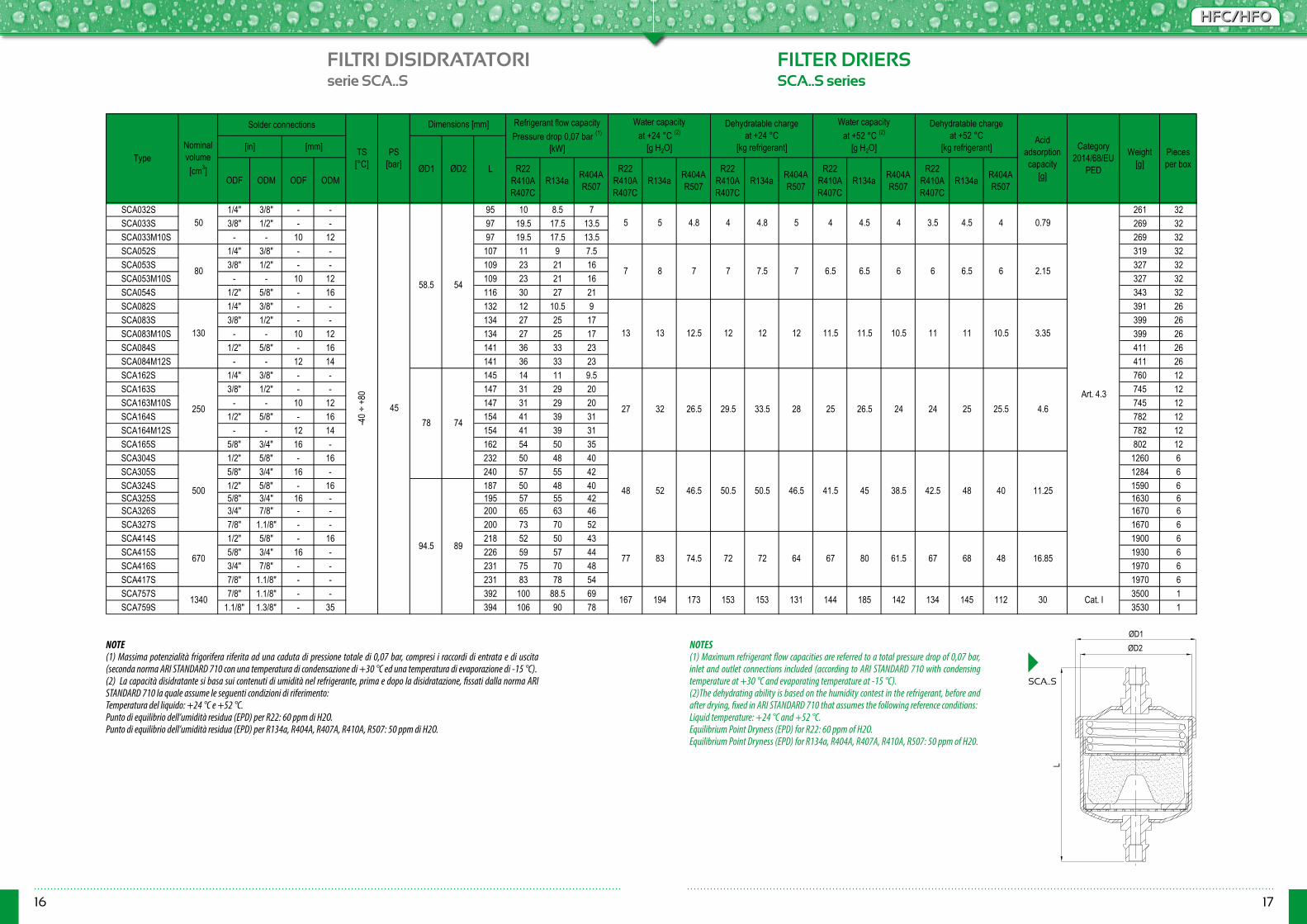
NOTE(1) Massima potenzialità frigorifera riferita ad una caduta di pressione totale di 0,07 bar, compresi i raccordi di entrata e di uscita (seconda norma ARI STANDARD 710 con una temperatura di condensazione di +30 °C ed una temperatura di evaporazione di -15 °C).(2) La capacità disidratante si basa sui contenuti di umidità nel refrigerante, prima e dopo la disidratazione, fissati dalla norma ARI STANDARD 710 la quale assume le seguenti condizioni di riferimento:Temperatura del liquido: +24 °C e +52 °C.Punto di equilibrio dell’umidità residua (EPD) per R22: 60 ppm di H2O.Punto di equilibrio dell’umidità residua (EPD) per R134a, R404A, R407A, R410A, R507: 50 ppm di H2O.
NOTES(1) Maximum refrigerant flow capacities are referred to a total pressure drop of 0,07 bar, inlet and outlet connections included (according to ARI STANDARD 710 with condensing temperature at +30 °C and evaporating temperature at -15 °C).(2)The dehydrating ability is based on the humidity contest in the refrigerant, before and after drying, fixed in ARI STANDARD 710 that assumes the following reference conditions:Liquid temperature: +24 °C and +52 °C.Equilibrium Point Dryness (EPD) for R22: 60 ppm of H2O.Equilibrium Point Dryness (EPD) for R134a, R404A, R407A, R410A, R507: 50 ppm of H2O.
CH
ØD1ØD2
L
ØD1
ØD2
L
CH
CH

12 13
HFC/HFOHFC/HFO
FILTRI DISIDRATATORI FILTER DRIERSserie SC..S SC..S series
SC..S
NOTE(1) Massima potenzialità frigorifera riferita ad una caduta di pressione totale di 0,07 bar, compresi i raccordi di entrata e di uscita (seconda norma ARI STANDARD 710 con una temperatura di condensazione di +30 °C ed una temperatura di evaporazione di -15 °C).(2) La capacità disidratante si basa sui contenuti di umidità nel refrigerante, prima e dopo la disidratazione, fissati dalla norma ARI STANDARD 710 la quale assume le seguenti condizioni di riferimento:Temperatura del liquido: +24 °C e +52 °C.Punto di equilibrio dell’umidità residua (EPD) per R22: 60 ppm di H2O.Punto di equilibrio dell’umidità residua (EPD) per R134a, R404A, R407A, R410A, R507: 50 ppm di H2O.
NOTES(1) Maximum refrigerant flow capacities are referred to a total pressure drop of 0,07 bar, inlet and outlet connections included (according to ARI STANDARD 710 with condensing temperature at +30 °C and evaporating temperature at -15 °C).(2)The dehydrating ability is based on the humidity contest in the refrigerant, before and after drying, fixed in ARI STANDARD 710 that assumes the following reference conditions:Liquid temperature: +24 °C and +52 °C.Equilibrium Point Dryness (EPD) for R22: 60 ppm of H2O.Equilibrium Point Dryness (EPD) for R134a, R404A, R407A, R410A, R507: 50 ppm of H20.
ODF ODM ODF ODMR22
R410A R407C
R134a R404A R507
R22 R410A R407C
R134a R404A R507
R22 R410A R407C
R134a R404A R507
R22 R410A R407C
R134a R404A R507
R22 R410A R407C
R134a R404A R507
SC032S 1/4" 3/8" - - 95 10 8.5 7 261 32SC033S 3/8" 1/2" - - 97 19.5 17.5 13.5 269 32SC033M10S - - 10 12 97 19.5 17.5 13.5 269 32SC052S 1/4" 3/8" - - 107 11 9 7.5 319 32SC053S 3/8" 1/2" - - 109 23 21 16 327 32SC053M10S - - 10 12 109 23 21 16 327 32SC054S 1/2" 5/8" - 16 116 30 27 21 343 32SC082S 1/4" 3/8" - - 132 12 10.5 9 391 26SC083S 3/8" 1/2" - - 134 27 25 17 399 26SC083M10S - - 10 12 134 27 25 17 399 26SC084S 1/2" 5/8" - 16 141 36 33 23 411 26SC084M12S - - 12 14 141 36 33 23 411 26SC162S 1/4" 3/8" - - 145 14 11 9.5 760 12SC163S 3/8" 1/2" - - 147 31 29 20 745 12SC163M10S - - 10 12 147 31 29 20 745 12SC164S 1/2" 5/8" - 16 154 41 39 31 782 12SC164M12S - - 12 14 154 41 39 31 782 12SC165S 5/8" 3/4" 16 - 162 54 50 35 802 12SC166S 3/4" 7/8" - - 167 62 58 39 842 12SC304S 1/2" 5/8" - 16 232 50 48 40 1260 6SC305S 5/8" 3/4" 16 - 240 57 55 42 1284 6SC324S 1/2" 5/8" - 16 187 50 48 40 1590 6SC325S 5/8" 3/4" 16 - 195 57 55 42 1630 6SC326S 3/4" 7/8" - - 200 65 63 46 1670 6SC327S 7/8" 1.1/8" - - 200 73 70 52 1670 6SC414S 1/2" 5/8" - 16 218 52 50 43 1900 6SC415S 5/8" 3/4" 16 - 226 59 57 44 1930 6SC416S 3/4" 7/8" - - 231 75 70 48 1970 6SC417S 7/8" 1.1/8" - - 231 83 78 54 1970 6SC757S 7/8" 1.1/8" - - 392 100 88.5 69 3500 1SC759S 1.1/8" 1.3/8" - 35 394 106 90 78 3530 1
670 96 104
185
80 84 100 77 84
Cat. I
60
1340 167 194 173 153 153 131 144
53 60 50
142 134 145 112
8593 90 90
52 56 48
37 42 35 31.5 33.5 30 31 32 28
500 60 65 58 63 63 58
13.5 14 14 13
25078 74
34 40 33
15 14 14
10 9 9 9.5 9 8
130 15 15 14.5 15.5 15.5
5 4.5 5.5 5
Art. 4.3
8 7.5 8 8 7
50
-40 ÷
+80
45
58.5 54
6
80 9
94.5 89
Water capacity at +52 °C (2)
[g H2O]
Dehydratable charge at +52 °C
[kg refrigerant] Category 2014/68/EU
PED
6.2 6 5 6 6 5 5.3
Weight [g]
Pieces per box
[in] [mm]
ØD1 ØD2 L
Refrigerant flow capacity Pressure drop 0,07 bar (1)
[kW]
Water capacity at +24 °C (2)
[g H2O]
Dehydratable charge at +24 °C
[kg refrigerant]Type
Nominal volume [cm3]
Solder connections
TS [°C]
PS [bar]
Dimensions [mm]
L
ØD1
ØD2

14 15
HFC/HFOHFC/HFO
FILTRI DISIDRATATORI FILTER DRIERSserie SCA..MM/MF SCA..MM/MF series
SCA..MF SCA..MM
ØD1 ØD2 L CHR22
R410A R407C
R134a R404A R507
R22 R410A R407C
R134a R404A R507
R22 R410A R407C
R134a R404A R507
R22 R410A R407C
R134a R404A R507
R22 R410A R407C
R134a R404A R507
SCA032MM 1/4" 103 16 10 8,5 7 285 32SCA032MF 1/4" 93 16/16 10 8,5 7 283 32SCA033MM 3/8" 111 16 19,5 17,5 13,5 299 32SCA052MM 1/4" 116 16 11 9 7,5 343 32SCA053MM 3/8" 124 16 23 21 16 357 32SCA082MM 1/4" 141 16 12 10,5 9 415 26SCA083MM 3/8" 149 16 27 25 17 429 26SCA083MF 3/8" 137 20/16 27 25 17 425 26SCA084MM 1/2" 157 19 36 33 23 461 26SCA162MM 1/4" 154 16 14 11 9,5 776 12SCA163MM 3/8" 162 16 31 29 20 790 12SCA164MM 1/2" 170 19 41 39 31 822 12SCA165MM 5/8" 179 23 54 50 35 882 12SCA304MM 1/2" 247 19 50 48 40 1440 6SCA305MM 5/8" 257 23 57 55 42 1460 6SCA324MM 1/2" 203 19 50 48 40 1650 6SCA325MM 5/8" 212 23 57 55 42 1710 6SCA414MM 1/2" 234 19 52 50 43 1950 6SCA415MM 5/8" 243 23 59 57 44 2010 6SCA416MM 3/4" 245 27 75 70 48 2050 6
8983
50
670
-40 ÷
+80
45
58,5
78
94,5
Weight [g]
41,5 45 38,5
33,5
48
Category 2014/68/EU
PED
42,5
25
6 6,5
500
250
130
80
74
74,5
28
72 72 64 67
46,5 50,5 50,5 46,552
25 26,5
77
24 24
80 67
27 32 26,5 29,5
TypeNominal volume [cm3]
SAE Flare
25,5
13 13 12,5 12
TS [°C]
PS [bar]
Dimensions [mm]Refrigerant flow capacity Pressure drop 0,07 bar (1)
[kW]
Water capacity at +24 °C (2)
[g H2O]
5 4,8
547 7 6,5 6,5
12 12 11,5
Art. 4.3
11
68
4,5 4
7
61,5
48 40
10,5
6
16,85
Dehydratable charge at +52 °C
[kg refrigerant]
3,35
4,6
11,25
11,5
6
48
2,15
0,79
Pieces per box
4,5 4
11 10,5
Acid adsorption capacity
[g]
4
Water capacity at +52 °C (2)
[g H2O]
3,54 54,8
Dehydratable charge at +24 °C
[kg refrigerant]
5
7,57 8
NOTE(1) Massima potenzialità frigorifera riferita ad una caduta di pressione totale di 0,07 bar, compresi i raccordi di entrata e di uscita (seconda norma ARI STANDARD 710 con una temperatura di condensazione di +30 °C ed una temperatura di evaporazione di -15 °C).(2) La capacità disidratante si basa sui contenuti di umidità nel refrigerante, prima e dopo la disidratazione, fissati dalla norma ARI STANDARD 710 la quale assume le seguenti condizioni di riferimento:Temperatura del liquido: +24 °C e +52 °C.Punto di equilibrio dell’umidità residua (EPD) per R22: 60 ppm di H2O.Punto di equilibrio dell’umidità residua (EPD) per R134a, R404A, R407A, R410A, R507: 50 ppm di H2O.
NOTES(1) Maximum refrigerant flow capacities are referred to a total pressure drop of 0,07 bar, inlet and outlet connections included (according to ARI STANDARD 710 with condensing temperature at +30 °C and evaporating temperature at -15 °C).(2)The dehydrating ability is based on the humidity contest in the refrigerant, before and after drying, fixed in ARI STANDARD 710 that assumes the following reference conditions:Liquid temperature: +24 °C and +52 °C.Equilibrium Point Dryness (EPD) for R22: 60 ppm of H2O.Equilibrium Point Dryness (EPD) for R134a, R404A, R407A, R410A, R507: 50 ppm of H2O.
CH
ØD1ØD2
L
ØD1
ØD2
L
CH
CH
16 17
HFC/HFOHFC/HFO
FILTRI DISIDRATATORI FILTER DRIERSserie SCA..S SCA..S series
SCA..S
NOTE(1) Massima potenzialità frigorifera riferita ad una caduta di pressione totale di 0,07 bar, compresi i raccordi di entrata e di uscita (seconda norma ARI STANDARD 710 con una temperatura di condensazione di +30 °C ed una temperatura di evaporazione di -15 °C).(2) La capacità disidratante si basa sui contenuti di umidità nel refrigerante, prima e dopo la disidratazione, fissati dalla norma ARI STANDARD 710 la quale assume le seguenti condizioni di riferimento:Temperatura del liquido: +24 °C e +52 °C.Punto di equilibrio dell’umidità residua (EPD) per R22: 60 ppm di H2O.Punto di equilibrio dell’umidità residua (EPD) per R134a, R404A, R407A, R410A, R507: 50 ppm di H2O.
NOTES(1) Maximum refrigerant flow capacities are referred to a total pressure drop of 0,07 bar, inlet and outlet connections included (according to ARI STANDARD 710 with condensing temperature at +30 °C and evaporating temperature at -15 °C).(2)The dehydrating ability is based on the humidity contest in the refrigerant, before and after drying, fixed in ARI STANDARD 710 that assumes the following reference conditions:Liquid temperature: +24 °C and +52 °C.Equilibrium Point Dryness (EPD) for R22: 60 ppm of H2O.Equilibrium Point Dryness (EPD) for R134a, R404A, R407A, R410A, R507: 50 ppm of H20.
ODF ODM ODF ODMR22
R410A R407C
R134a R404A R507
R22 R410A R407C
R134a R404A R507
R22 R410A R407C
R134a R404A R507
R22 R410A R407C
R134a R404A R507
R22 R410A R407C
R134a R404A R507
SCA032S 1/4" 3/8" - - 95 10 8.5 7 261 32SCA033S 3/8" 1/2" - - 97 19.5 17.5 13.5 269 32SCA033M10S - - 10 12 97 19.5 17.5 13.5 269 32SCA052S 1/4" 3/8" - - 107 11 9 7.5 319 32SCA053S 3/8" 1/2" - - 109 23 21 16 327 32SCA053M10S - - 10 12 109 23 21 16 327 32SCA054S 1/2" 5/8" - 16 116 30 27 21 343 32SCA082S 1/4" 3/8" - - 132 12 10.5 9 391 26SCA083S 3/8" 1/2" - - 134 27 25 17 399 26SCA083M10S - - 10 12 134 27 25 17 399 26SCA084S 1/2" 5/8" - 16 141 36 33 23 411 26SCA084M12S - - 12 14 141 36 33 23 411 26SCA162S 1/4" 3/8" - - 145 14 11 9.5 760 12SCA163S 3/8" 1/2" - - 147 31 29 20 745 12SCA163M10S - - 10 12 147 31 29 20 745 12SCA164S 1/2" 5/8" - 16 154 41 39 31 782 12SCA164M12S - - 12 14 154 41 39 31 782 12SCA165S 5/8" 3/4" 16 - 162 54 50 35 802 12SCA304S 1/2" 5/8" - 16 232 50 48 40 1260 6SCA305S 5/8" 3/4" 16 - 240 57 55 42 1284 6SCA324S 1/2" 5/8" - 16 187 50 48 40 1590 6SCA325S 5/8" 3/4" 16 - 195 57 55 42 1630 6SCA326S 3/4" 7/8" - - 200 65 63 46 1670 6SCA327S 7/8" 1.1/8" - - 200 73 70 52 1670 6SCA414S 1/2" 5/8" - 16 218 52 50 43 1900 6SCA415S 5/8" 3/4" 16 - 226 59 57 44 1930 6SCA416S 3/4" 7/8" - - 231 75 70 48 1970 6SCA417S 7/8" 1.1/8" - - 231 83 78 54 1970 6SCA757S 7/8" 1.1/8" - - 392 100 88.5 69 3500 1SCA759S 1.1/8" 1.3/8" - 35 394 106 90 78 3530 1
Cat. I30
Art. 4.3
8994.5
45
144 185 142 134 145 112167 194 173 153 153 131
Pieces per box
250
Refrigerant flow capacity Pressure drop 0,07 bar (1)
[kW]
5
Solder connections
TS [°C]
PS [bar]
Water capacity at +24 °C (2)
[g H2O]
Dehydratable charge at +24 °C
[kg refrigerant]
Water capacity at +52 °C (2)
[g H2O]
Dimensions [mm]
58.5 54
[mm]
78 74
ØD1 ØD2 LType
Nominal volume [cm3]
50
80
130
454.844.8
Weight [g]
Acid adsorption capacity
[g]
Category 2014/68/EU
PED
4.5
6 6.5 6
Dehydratable charge at +52 °C
[kg refrigerant]
10.5
5 0.79
2.15
3.35
4.6
7 7 7.5 7
11.25
44.53.54
670
500
16.8548
8
[in]
-40 ÷
+80
1340
25
11
42.5 48
11
24
7
77 83 74.5 72 72 67
6.5 6.5 6
68
24
12
64 67 80 61.5
13 11.512
40
25.5
45
10.511.5
38.5
26.533.5 28 25
50.5 50.5 46.5 41.5
13
27 32 26.5 29.5
48 52 46.5
1212.5
L
ØD1
ØD2
18 19
HFC/HFOHFC/HFO
FILTRI DISIDRATATORI FILTER DRIERSserie MSD MSD series
NOTE(1) Massima potenzialità frigorifera riferita ad una caduta di pressione totale di 0,07 bar, compresi i raccordi di entrata e di uscita (seconda norma ARI STANDARD 710 con una temperatura di condensazione di +30 °C ed una temperatura di evaporazione di -15 °C).(2) La capacità disidratante si basa sui contenuti di umidità nel refrigerante, prima e dopo la disidratazione, fissati dalla norma ARI STANDARD 710 la quale assume le seguenti condizioni di riferimento:Temperatura del liquido: +24 °C e +52 °C.Punto di equilibrio dell’umidità residua (EPD) per R22: 60 ppm di H2O.Punto di equilibrio dell’umidità residua (EPD) per R134a, R404A, R407A, R410A, R507: 50 ppm di H2O.
NOTES(1) Maximum refrigerant flow capacities are referred to a total pressure drop of 0,07 bar, inlet and outlet connections included (according to ARI STANDARD 710 with condensing temperature at +30 °C and evaporating temperature at -15 °C).(2)The dehydrating ability is based on the humidity contest in the refrigerant, before and after drying, fixed in ARI STANDARD 710 that assumes the following reference conditions:Liquid temperature: +24 °C and +52 °C.Equilibrium Point Dryness (EPD) for R22: 60 ppm of H2O.Equilibrium Point Dryness (EPD) for R134a, R404A, R407A, R410A, R507: 50 ppm of H20.
ODF ODM ODF ODM ØD1 ØD2 L CHR22
R410A R407C
R134a R404A R507
R22 R410A R407C
R134a R404A R507
R22 R410A R407C
R134a R404A R507
R22 R410A R407C
R134a R404A R507
R22 R410A R407C
R134a R404A R507
MSD032MM 1/4" - - - - 103 16 6,2 6 4 285 32MSD032MF 1/4" - - - - 93 16/16 6,2 6 4 283 32MSD032S - 1/4" 3/8" - - 95 - 6,2 6 4 261 32MSD033MM 3/8" - - - - 111 16 19 17 13 299 32MSD033S - 3/8" 1/2" - - 97 - 19 17 13 269 32MSD033M10S - - - 10 12 97 - 19 17 13 269 32MSD052MM 1/4" - - - - 116 16 7 6,6 4,4 343 32MSD052S - 1/4" 3/8" - - 107 - 7 6,6 4,4 319 32MSD053MM 3/8" - - - - 124 16 19 18 14 357 32MSD053S - 3/8" 1/2" - - 109 - 19 18 14 327 32MSD053M10S - - - 10 12 109 - 19 18 14 327 32MSD082MM 1/4" - - - - 141 16 8 7 5 415 26MSD082S - 1/4" 3/8" - - 132 - 8 7 5 391 26MSD083MM 3/8" - - - - 149 16 20 18,5 13 429 26MSD083MF 3/8" - - - - 137 20/16 20 18,5 13 425 26MSD083S - 3/8" 1/2" - - 134 - 20 18,5 13 399 26MSD083M10S - - - 10 12 134 - 20 18,5 13 399 26MSD084MM 1/2" - - - - 157 19 29 26 20 461 26MSD084S - 1/2" 5/8" - 16 141 - 29 26 20 411 26MSD084M12S - - - 12 14 141 - 29 26 20 411 26MSD162MM 1/4" - - - - 154 16 10 9 7 776 12MSD162S - 1/4" 3/8" - - 145 - 10 9 7 760 12MSD163MM 3/8" - - - - 162 16 26 25 19 790 12MSD163S - 3/8" 1/2" - - 147 - 26 25 19 745 12MSD163M10S - - - 10 12 147 - 26 25 19 745 12MSD164MM 1/2" - - - - 170 19 39 37 30 822 12MSD164S - 1/2" 5/8" - 16 154 - 39 37 30 782 12MSD164M12S - - - 12 14 154 - 39 37 30 782 12MSD165MM 5/8" - - - - 179 23 49 45 32 882 12MSD165S - 5/8" 3/4" 16 - 162 - 49 45 32 802 12MSD324MM 1/2" - - - - 203 19 49 46 33 1650 6MSD324S - 1/2" 5/8" - 16 187 - 49 46 33 1590 6MSD325MM 5/8" - - - - 212 23 55 54 37 1710 6MSD325S - 5/8" 3/4" 16 - 195 - 55 54 37 1630 6MSD414MM 1/2" - - - - 234 19 51 48 35 1950 6MSD414S - 1/2" 5/8" - 16 218 - 51 48 35 1900 6MSD415MM 5/8" - - - - 243 23 57 55 40 2010 6MSD415S - 5/8" 3/4" 16 - 226 - 57 55 40 1930 6MSD416MM 3/4" - - - - 245 27 66 63 43 2050 6MSD416S - 3/4" 7/8" - - 231 - 66 63 43 1970 6MSD417S - 7/8" 1.1/8" - - 231 - 75 70 45 1970 6
35 32
90
60 6570 65 6566
104 95
66
104 104112 95
70
112
35
5,5
Art. 4.3
91
14,5 14,5
70
14
90
5263
90
6357
6 5,5 6
14,5
8,5 8,5 7,5
33 35
8,59,5 10 9,5
16 15,516 1515
TypeNominal volume [cm3]
SAE Flare
45 3840
16
74
-40 ÷
+80
89
36,5250 78
16 15,5
7
130
80
50
45
58,5 54
500
94,5
670
6,5 7
37 45
66,5
9 9
40
10 11 10
7 7,5 7
TS [°C]
Pieces per box
[in] [mm]Dimensions [mm]
Refrigerant flow capacity Pressure drop 0,07 bar (1)
[kW]
Water capacity at +24 °C (2)
[g H2O]
Dehydratable charge at +24 °C
[kg refrigerant]
Water capacity at +52 °C (2)
[g H2O]
Dehydratable charge at +52 °C
[kg refrigerant]
Solder connections
Category 2014/68/EU
PED
Weight [g]
PS [bar]
MSD..MM
MSD..S
MSD..MF
ØD2
ØD1
L
CH
L
ØD2
ØD1
ØD2
ØD1
L
CH
20 21
HFC/HFOHFC/HFO
FILTRI A RETE FILTER STRAINERSserie S S series
S..MM S..S
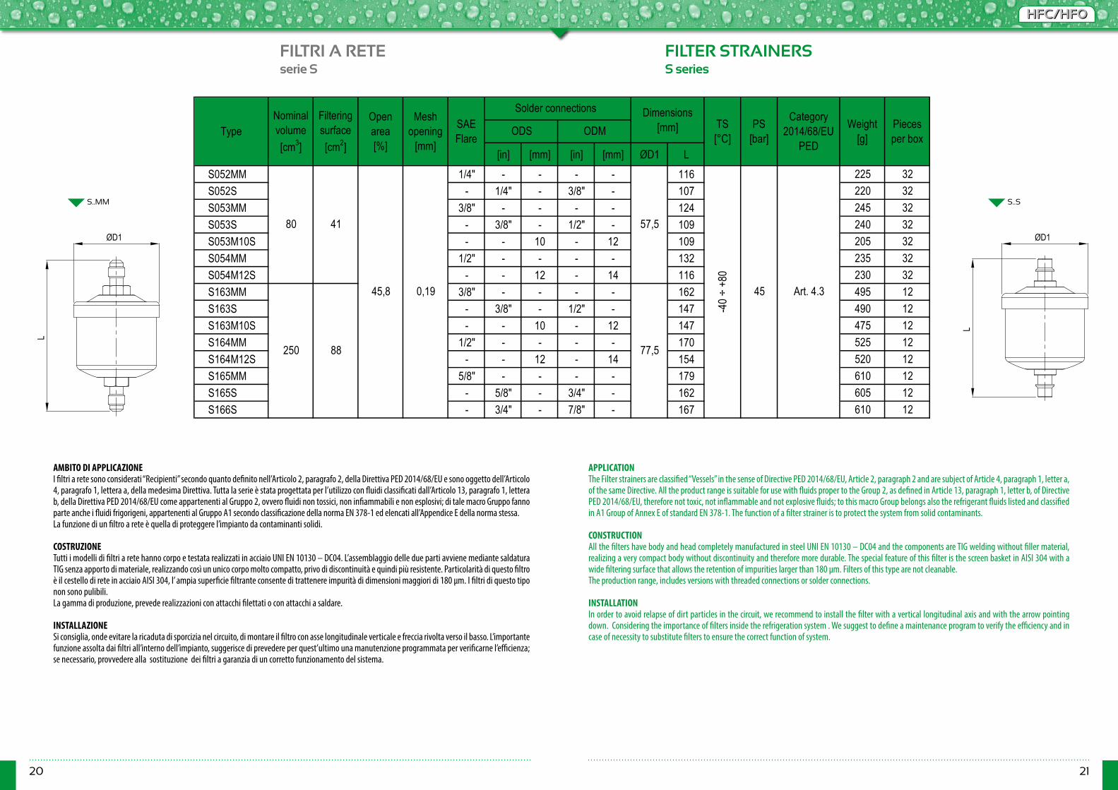
[in] [mm] [in] [mm] ØD1 LS052MM 1/4" - - - - 116 225 32S052S - 1/4" - 3/8" - 107 220 32S053MM 3/8" - - - - 124 245 32S053S - 3/8" - 1/2" - 109 240 32S053M10S - - 10 - 12 109 205 32S054MM 1/2" - - - - 132 235 32S054M12S - - 12 - 14 116 230 32S163MM 3/8" - - - - 162 495 12S163S - 3/8" - 1/2" - 147 490 12S163M10S - - 10 - 12 147 475 12S164MM 1/2" - - - - 170 525 12S164M12S - - 12 - 14 154 520 12S165MM 5/8" - - - - 179 610 12S165S - 5/8" - 3/4" - 162 605 12S166S - 3/4" - 7/8" - 167 610 12
88
45,8
Type ODS ODMSAE Flare
Solder connections Nominal volume [cm3]
Meshopening
[mm]
Filteringsurface[cm2]
Open area[%]
0,19
57,5
Weight [g]
Pieces per box
Art. 4.3
80 41
Category 2014/68/EU
PED
Dimensions [mm]
-40 ÷
+80
TS [°C]
PS [bar]
45
250 77,5
AMBITO DI APPLICAZIONEI filtri a rete sono considerati “Recipienti” secondo quanto definito nell’Articolo 2, paragrafo 2, della Direttiva PED 2014/68/EU e sono oggetto dell’Articolo 4, paragrafo 1, lettera a, della medesima Direttiva. Tutta la serie è stata progettata per l’utilizzo con fluidi classificati dall’Articolo 13, paragrafo 1, lettera b, della Direttiva PED 2014/68/EU come appartenenti al Gruppo 2, ovvero fluidi non tossici, non infiammabili e non esplosivi; di tale macro Gruppo fanno parte anche i fluidi frigorigeni, appartenenti al Gruppo A1 secondo classificazione della norma EN 378-1 ed elencati all’Appendice E della norma stessa. La funzione di un filtro a rete è quella di proteggere l’impianto da contaminanti solidi.
COSTRUZIONETutti i modelli di filtri a rete hanno corpo e testata realizzati in acciaio UNI EN 10130 – DC04. L’assemblaggio delle due parti avviene mediante saldatura TIG senza apporto di materiale, realizzando così un unico corpo molto compatto, privo di discontinuità e quindi più resistente. Particolarità di questo filtro è il cestello di rete in acciaio AISI 304, l’ ampia superficie filtrante consente di trattenere impurità di dimensioni maggiori di 180 μm. I filtri di questo tipo non sono pulibili.La gamma di produzione, prevede realizzazioni con attacchi filettati o con attacchi a saldare. INSTALLAZIONESi consiglia, onde evitare la ricaduta di sporcizia nel circuito, di montare il filtro con asse longitudinale verticale e freccia rivolta verso il basso. L’importante funzione assolta dai filtri all’interno dell’impianto, suggerisce di prevedere per quest’ultimo una manutenzione programmata per verificarne l’efficienza; se necessario, provvedere alla sostituzione dei filtri a garanzia di un corretto funzionamento del sistema.
APPLICATIONThe Filter strainers are classified “Vessels” in the sense of Directive PED 2014/68/EU, Article 2, paragraph 2 and are subject of Article 4, paragraph 1, letter a, of the same Directive. All the product range is suitable for use with fluids proper to the Group 2, as defined in Article 13, paragraph 1, letter b, of Directive PED 2014/68/EU, therefore not toxic, not inflammable and not explosive fluids; to this macro Group belongs also the refrigerant fluids listed and classified in A1 Group of Annex E of standard EN 378-1. The function of a filter strainer is to protect the system from solid contaminants. CONSTRUCTIONAll the filters have body and head completely manufactured in steel UNI EN 10130 – DC04 and the components are TIG welding without filler material, realizing a very compact body without discontinuity and therefore more durable. The special feature of this filter is the screen basket in AISI 304 with a wide filtering surface that allows the retention of impurities larger than 180 μm. Filters of this type are not cleanable.The production range, includes versions with threaded connections or solder connections.
INSTALLATIONIn order to avoid relapse of dirt particles in the circuit, we recommend to install the filter with a vertical longitudinal axis and with the arrow pointing down. Considering the importance of filters inside the refrigeration system . We suggest to define a maintenance program to verify the efficiency and in case of necessity to substitute filters to ensure the correct function of system.
ØD1
L
ØD1
L
22 23
HFC/HFOHFC/HFO
FILTRI DISIDRATATORI CON INDICATORE FILTER DRIERS WITH INDICATORserie SCMI SCMI series
SCMI..MM
ODF ODM ODF ODM ØD1 ØD2 L CHR22
R410A R407C
R134a R404A R507
R22 R410A R407C
R134a R404A R507
R22 R410A R407C
R134a R404A R507
R22 R410A R407C
R134a R404A R507
R22 R410A R407C
R134a R404A R507
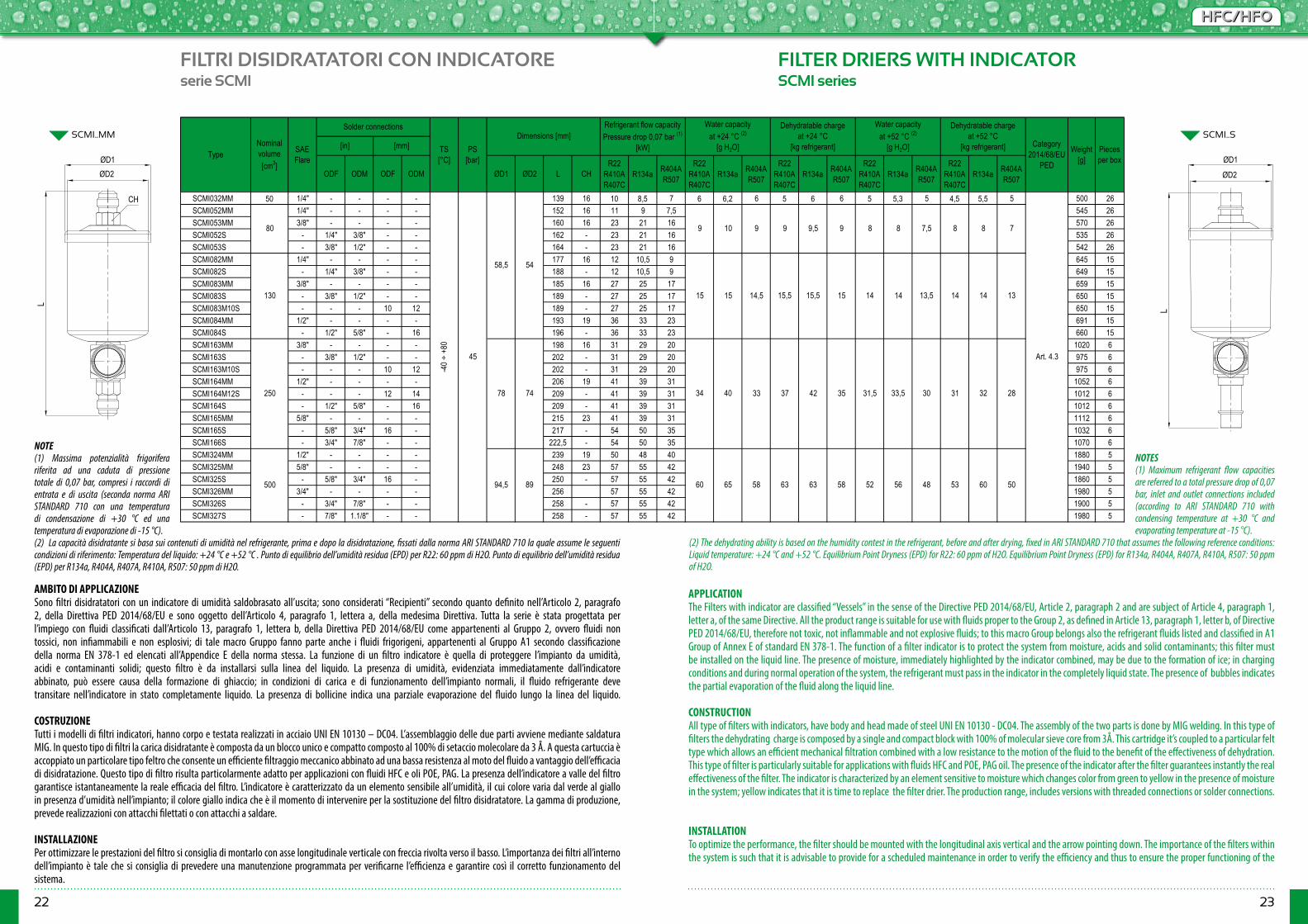
SCMI032MM 50 1/4" - - - - 139 16 10 8,5 7 6 6,2 6 5 6 6 5 5,3 5 4,5 5,5 5 500 26SCMI052MM 1/4" - - - - 152 16 11 9 7,5 545 26SCMI053MM 3/8" - - - - 160 16 23 21 16 570 26SCMI052S - 1/4" 3/8" - - 162 - 23 21 16 535 26SCMI053S - 3/8" 1/2" - - 164 - 23 21 16 542 26SCMI082MM 1/4" - - - - 177 16 12 10,5 9 645 15SCMI082S - 1/4" 3/8" - - 188 - 12 10,5 9 649 15SCMI083MM 3/8" - - - - 185 16 27 25 17 659 15SCMI083S - 3/8" 1/2" - - 189 - 27 25 17 650 15SCMI083M10S - - - 10 12 189 - 27 25 17 650 15SCMI084MM 1/2" - - - - 193 19 36 33 23 691 15SCMI084S - 1/2" 5/8" - 16 196 - 36 33 23 660 15SCMI163MM 3/8" - - - - 198 16 31 29 20 1020 6SCMI163S - 3/8" 1/2" - - 202 - 31 29 20 975 6SCMI163M10S - - - 10 12 202 - 31 29 20 975 6SCMI164MM 1/2" - - - - 206 19 41 39 31 1052 6SCMI164M12S - - - 12 14 209 - 41 39 31 1012 6SCMI164S - 1/2" 5/8" - 16 209 - 41 39 31 1012 6SCMI165MM 5/8" - - - - 215 23 41 39 31 1112 6SCMI165S - 5/8" 3/4" 16 - 217 - 54 50 35 1032 6SCMI166S - 3/4" 7/8" - - 222,5 - 54 50 35 1070 6SCMI324MM 1/2" - - - - 239 19 50 48 40 1880 5SCMI325MM 5/8" - - - - 248 23 57 55 42 1940 5SCMI325S - 5/8" 3/4" 16 - 250 - 57 55 42 1860 5SCMI326MM 3/4" - - - - 256 57 55 42 1980 5SCMI326S - 3/4" 7/8" - - 258 - 57 55 42 1900 5SCMI327S - 7/8" 1.1/8" - - 258 - 57 55 42 1980 5
32 28
53
33,5 30
60 50
34
89 60 65 58 63 63 4858 52 56
40
1415,5 15,5 13,514
Pieces per box
13
Weight [g]
9 8
33 37
15 14 14
42 35 3131,5
15 15 14,5
78 74
8 8 79 9,5
94,5
Art. 4.3
80 9 10 9 8 7,5
54
130
TS [°C]
PS [bar]
Dimensions [mm]Solder connections
Nominal volume [cm3]
-40 ÷
+80
250
500
45
58,5
Type[in] [mm] Category
2014/68/EU PED
Refrigerant flow capacity Pressure drop 0,07 bar (1)
[kW]
Water capacity at +24 °C (2)
[g H2O]
Dehydratable charge at +24 °C
[kg refrigerant]
Water capacity at +52 °C (2)
[g H2O]
Dehydratable charge at +52 °C
[kg refrigerant]SAE Flare
AMBITO DI APPLICAZIONESono filtri disidratatori con un indicatore di umidità saldobrasato all’uscita; sono considerati “Recipienti” secondo quanto definito nell’Articolo 2, paragrafo 2, della Direttiva PED 2014/68/EU e sono oggetto dell’Articolo 4, paragrafo 1, lettera a, della medesima Direttiva. Tutta la serie è stata progettata per l’impiego con fluidi classificati dall’Articolo 13, paragrafo 1, lettera b, della Direttiva PED 2014/68/EU come appartenenti al Gruppo 2, ovvero fluidi non tossici, non infiammabili e non esplosivi; di tale macro Gruppo fanno parte anche i fluidi frigorigeni, appartenenti al Gruppo A1 secondo classificazione della norma EN 378-1 ed elencati all’Appendice E della norma stessa. La funzione di un filtro indicatore è quella di proteggere l’impianto da umidità, acidi e contaminanti solidi; questo filtro è da installarsi sulla linea del liquido. La presenza di umidità, evidenziata immediatamente dall’indicatore abbinato, può essere causa della formazione di ghiaccio; in condizioni di carica e di funzionamento dell’impianto normali, il fluido refrigerante deve transitare nell’indicatore in stato completamente liquido. La presenza di bollicine indica una parziale evaporazione del fluido lungo la linea del liquido.
COSTRUZIONETutti i modelli di filtri indicatori, hanno corpo e testata realizzati in acciaio UNI EN 10130 – DC04. L’assemblaggio delle due parti avviene mediante saldatura MIG. In questo tipo di filtri la carica disidratante è composta da un blocco unico e compatto composto al 100% di setaccio molecolare da 3 Å. A questa cartuccia è accoppiato un particolare tipo feltro che consente un efficiente filtraggio meccanico abbinato ad una bassa resistenza al moto del fluido a vantaggio dell’efficacia di disidratazione. Questo tipo di filtro risulta particolarmente adatto per applicazioni con fluidi HFC e oli POE, PAG. La presenza dell’indicatore a valle del filtro garantisce istantaneamente la reale efficacia del filtro. L’indicatore è caratterizzato da un elemento sensibile all’umidità, il cui colore varia dal verde al giallo in presenza d’umidità nell’impianto; il colore giallo indica che è il momento di intervenire per la sostituzione del filtro disidratatore. La gamma di produzione, prevede realizzazioni con attacchi filettati o con attacchi a saldare.
INSTALLAZIONEPer ottimizzare le prestazioni del filtro si consiglia di montarlo con asse longitudinale verticale con freccia rivolta verso il basso. L’importanza dei filtri all’interno dell’impianto è tale che si consiglia di prevedere una manutenzione programmata per verificarne l’efficienza e garantire così il corretto funzionamento del sistema.
APPLICATIONThe Filters with indicator are classified “Vessels” in the sense of the Directive PED 2014/68/EU, Article 2, paragraph 2 and are subject of Article 4, paragraph 1, letter a, of the same Directive. All the product range is suitable for use with fluids proper to the Group 2, as defined in Article 13, paragraph 1, letter b, of Directive PED 2014/68/EU, therefore not toxic, not inflammable and not explosive fluids; to this macro Group belongs also the refrigerant fluids listed and classified in A1 Group of Annex E of standard EN 378-1. The function of a filter indicator is to protect the system from moisture, acids and solid contaminants; this filter must be installed on the liquid line. The presence of moisture, immediately highlighted by the indicator combined, may be due to the formation of ice; in charging conditions and during normal operation of the system, the refrigerant must pass in the indicator in the completely liquid state. The presence of bubbles indicates the partial evaporation of the fluid along the liquid line. CONSTRUCTIONAll type of filters with indicators, have body and head made of steel UNI EN 10130 - DC04. The assembly of the two parts is done by MIG welding. In this type of filters the dehydrating charge is composed by a single and compact block with 100% of molecular sieve core from 3Å. This cartridge it’s coupled to a particular felt type which allows an efficient mechanical filtration combined with a low resistance to the motion of the fluid to the benefit of the effectiveness of dehydration. This type of filter is particularly suitable for applications with fluids HFC and POE, PAG oil. The presence of the indicator after the filter guarantees instantly the real effectiveness of the filter. The indicator is characterized by an element sensitive to moisture which changes color from green to yellow in the presence of moisture in the system; yellow indicates that it is time to replace the filter drier. The production range, includes versions with threaded connections or solder connections.
INSTALLATIONTo optimize the performance, the filter should be mounted with the longitudinal axis vertical and the arrow pointing down. The importance of the filters within the system is such that it is advisable to provide for a scheduled maintenance in order to verify the efficiency and thus to ensure the proper functioning of the
SCMI..S
NOTE(1) Massima potenzialità frigorifera riferita ad una caduta di pressione totale di 0,07 bar, compresi i raccordi di entrata e di uscita (seconda norma ARI STANDARD 710 con una temperatura di condensazione di +30 °C ed una temperatura di evaporazione di -15 °C).(2) La capacità disidratante si basa sui contenuti di umidità nel refrigerante, prima e dopo la disidratazione, fissati dalla norma ARI STANDARD 710 la quale assume le seguenti condizioni di riferimento: Temperatura del liquido: +24 °C e +52 °C . Punto di equilibrio dell’umidità residua (EPD) per R22: 60 ppm di H2O. Punto di equilibrio dell’umidità residua (EPD) per R134a, R404A, R407A, R410A, R507: 50 ppm di H2O.
NOTES(1) Maximum refrigerant flow capacities are referred to a total pressure drop of 0,07 bar, inlet and outlet connections included (according to ARI STANDARD 710 with condensing temperature at +30 °C and evaporating temperature at -15 °C).
(2) The dehydrating ability is based on the humidity contest in the refrigerant, before and after drying, fixed in ARI STANDARD 710 that assumes the following reference conditions: Liquid temperature: +24 °C and +52 °C. Equilibrium Point Dryness (EPD) for R22: 60 ppm of H2O. Equilibrium Point Dryness (EPD) for R134a, R404A, R407A, R410A, R507: 50 ppm of H2O.
L
ØD1
CH
ØD2
L
ØD1
ØD2
24 25
HFC/HFOHFC/HFO
FILTRI A CARTUCCIA SOLIDA RICAMBIABILE REPLACEABLE SOLID CORE FILTERSserie CSR CSR series
CSR
NOTE(1) Massima potenzialità frigorifera riferita ad una caduta di pressione totale di 0,07 bar, compresi i raccordi di entrata e di uscita (seconda norma ARI STANDARD 710 con una temperatura di condensazione di +30 °C ed una temperatura di evaporazione di -15 °C).(2) La capacità disidratante si basa sui contenuti di umidità nel refrigerante, prima e dopo la disidratazione, fissati dalla norma ARI STANDARD 710 la quale assume le seguenti condizioni di riferimento: Temperatura del liquido: +24 °C e +52 °C. Punto di equilibrio dell’umidità residua (EPD) per R22: 60 ppm di H2O. Punto di equilibrio dell’umidità residua (EPD) per R134a, R404A, R407A, R410A, R507: 50 ppm di H2O.
NOTES(1) Maximum refrigerant flow capacities are referred to a total pressure drop of 0,07 bar, inlet and outlet connections included (according to ARI STANDARD 710 with condensing temperature at +30 °C and evaporating temperature at -15 °C).(2)The dehydrating ability is based on the humidity contest in the refrigerant, before and after drying, fixed in ARI STANDARD 710 that assumes the following reference conditions:Liquid temperature: +24 °C and +52 °C.Equilibrium Point Dryness (EPD) for R22: 60 ppm of H2O.Equilibrium Point Dryness (EPD) for R134a, R404A, R407A, R410A, R507: 50 ppm of H20.
[in] [mm] ØD1 ØD2 H H1 P E K
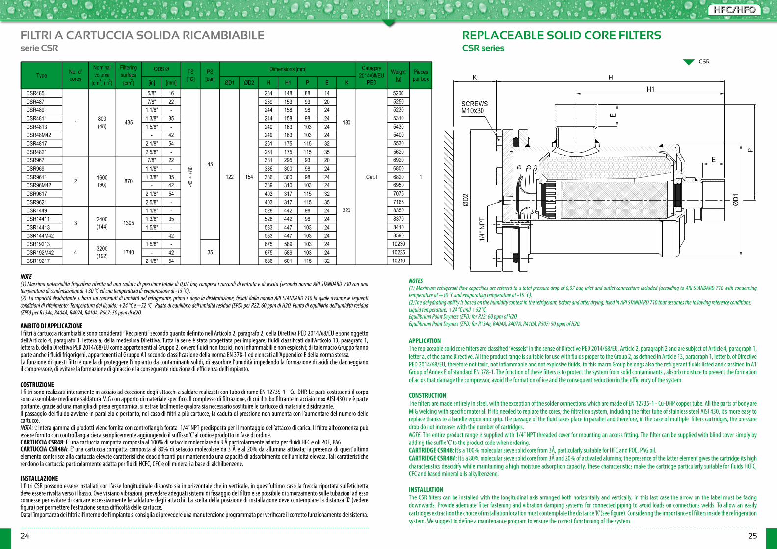
CSR485 5/8" 16 234 148 88 14 5200CSR487 7/8" 22 239 153 93 20 5250CSR489 1.1/8" - 244 158 98 24 5230CSR4811 1.3/8" 35 244 158 98 24 5310CSR4813 1.5/8" - 249 163 103 24 5430CSR48M42 - 42 249 163 103 24 5400CSR4817 2.1/8" 54 261 175 115 32 5530CSR4821 2.5/8" - 261 175 115 35 5620CSR967 7/8" 22 381 295 93 20 6920CSR969 1.1/8" - 386 300 98 24 6800CSR9611 1.3/8" 35 386 300 98 24 6820CSR96M42 - 42 389 310 103 24 6950CSR9617 2.1/8" 54 403 317 115 32 7075CSR9621 2.5/8" - 403 317 115 35 7165CSR1449 1.1/8" - 528 442 98 24 8350CSR14411 1.3/8" 35 528 442 98 24 8370CSR14413 1.5/8" - 533 447 103 24 8410CSR144M42 - 42 533 447 103 24 8590CSR19213 1.5/8" - 675 589 103 24 10230CSR192M42 - 42 675 589 103 24 10225CSR19217 2.1/8" 54 686 601 115 32 10210
TS [°C]
Pieces per box
1
Category 2014/68/EU
PED
Cat. I
Weight [g]
320
180
TypeNominal volume
[cm3] (in3)
800 (48)
ODS ØNo. of cores
Filtering surface [cm2]
435
PS [bar]
45
Dimensions [mm]
154122
35
1600 (96)2
1
3
870-4
0 ÷ +
80
1305
4 3200 (192) 1740
2400 (144)
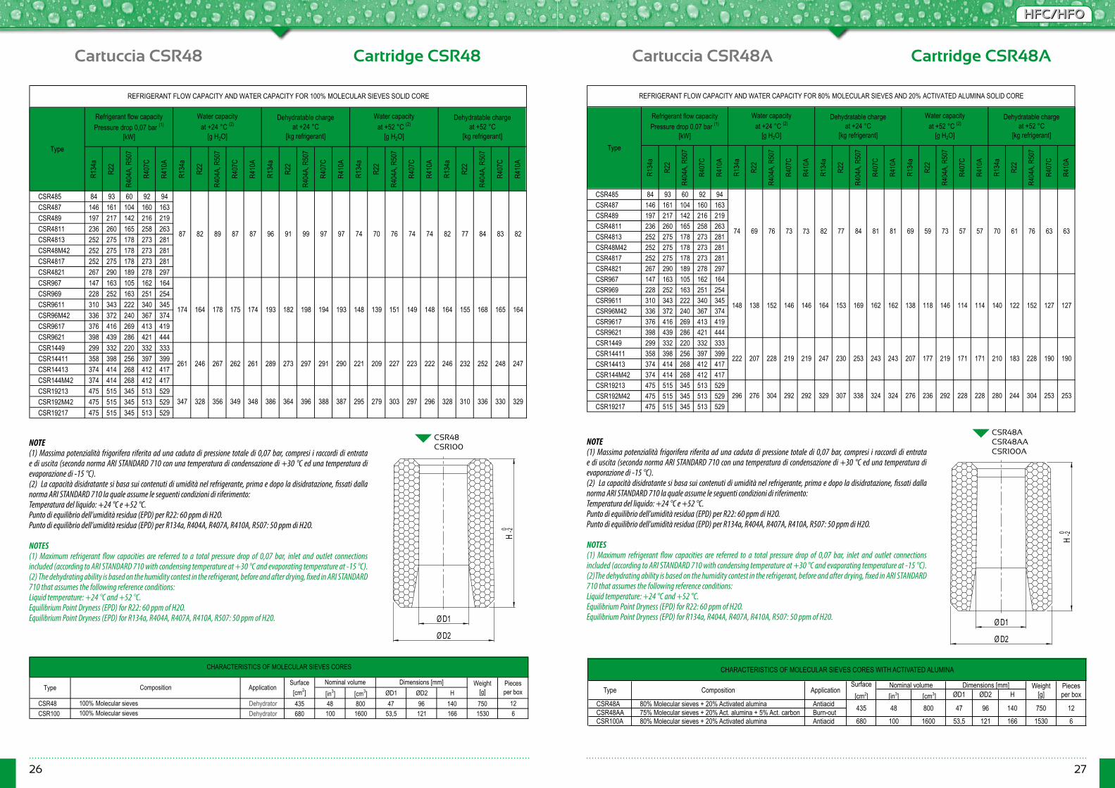
AMBITO DI APPLICAZIONEI filtri a cartuccia ricambiabile sono considerati “Recipienti” secondo quanto definito nell’Articolo 2, paragrafo 2, della Direttiva PED 2014/68/EU e sono oggetto dell’Articolo 4, paragrafo 1, lettera a, della medesima Direttiva. Tutta la serie è stata progettata per impiegare, fluidi classificati dall’Articolo 13, paragrafo 1, lettera b, della Direttiva PED 2014/68/EU come appartenenti al Gruppo 2, ovvero fluidi non tossici, non infiammabili e non esplosivi; di tale macro Gruppo fanno parte anche i fluidi frigorigeni, appartenenti al Gruppo A1 secondo classificazione della norma EN 378-1 ed elencati all’Appendice E della norma stessa.La funzione di questi filtri è quella di proteggere l’impianto da contaminanti solidi, di assorbire l’umidità impedendo la formazione di acidi che danneggiano il compressore, di evitare la formazione di ghiaccio e la conseguente riduzione di efficienza dell’impianto.
COSTRUZIONEI filtri sono realizzati interamente in acciaio ad eccezione degli attacchi a saldare realizzati con tubo di rame EN 12735-1 - Cu-DHP. Le parti costituenti il corpo sono assemblate mediante saldatura MIG con apporto di materiale specifico. Il complesso di filtrazione, di cui il tubo filtrante in acciaio inox AISI 430 ne è parte portante, grazie ad una maniglia di presa ergonomica, si estrae facilmente qualora sia necessario sostituire le cartucce di materiale disidratante. Il passaggio del fluido avviene in parallelo e pertanto, nel caso di filtri a più cartucce, la caduta di pressione non aumenta con l’aumentare del numero delle cartucce.NOTA: L’ intera gamma di prodotti viene fornita con controflangia forata 1/4” NPT predisposta per il montaggio dell’attacco di carica. Il filtro all’occorrenza può essere fornito con controflangia cieca semplicemente aggiungendo il suffisso ‘C’ al codice prodotto in fase di ordine. CARTUCCIA CSR48: E’ una cartuccia compatta composta al 100% di setaccio molecolare da 3 Å particolarmente adatta per fluidi HFC e oli POE, PAG.CARTUCCIA CSR48A: E’ una cartuccia compatta composta al 80% di setaccio molecolare da 3 Å e al 20% da allumina attivata; la presenza di quest’ultimo elemento conferisce alla cartuccia elevate caratteristiche deacidificanti pur mantenendo una capacità di adsorbimento dell’umidità elevata. Tali caratteristiche rendono la cartuccia particolarmente adatta per fluidi HCFC, CFC e oli minerali a base di alchilbenzene.
INSTALLAZIONEI filtri CSR possono essere installati con l’asse longitudinale disposto sia in orizzontale che in verticale, in quest’ultimo caso la freccia riportata sull’etichetta deve essere rivolta verso il basso. Ove vi siano vibrazioni, prevedere adeguati sistemi di fissaggio del filtro e se possibile di smorzamento sulle tubazioni ad esso connesse per evitare di caricare eccessivamente le saldature degli attacchi. La scelta della posizione di installazione deve contemplare la distanza ‘K’ (vedere figura) per permettere l’estrazione senza difficoltà delle cartucce.Data l’importanza dei filtri all’interno dell’impianto si consiglia di prevedere una manutenzione programmata per verificare il corretto funzionamento del sistema.
APPLICATIONThe replaceable solid core filters are classified “Vessels” in the sense of Directive PED 2014/68/EU, Article 2, paragraph 2 and are subject of Article 4, paragraph 1, letter a, of the same Directive. All the product range is suitable for use with fluids proper to the Group 2, as defined in Article 13, paragraph 1, letter b, of Directive PED 2014/68/EU, therefore not toxic, not inflammable and not explosive fluids; to this macro Group belongs also the refrigerant fluids listed and classified in A1 Group of Annex E of standard EN 378-1. The function of these filters is to protect the system from solid contaminants , absorb moisture to prevent the formation of acids that damage the compressor, avoid the formation of ice and the consequent reduction in the efficiency of the system.
CONSTRUCTIONThe filters are made entirely in steel, with the exception of the solder connections which are made of EN 12735-1 - Cu-DHP copper tube. All the parts of body are MIG welding with specific material. If it’s needed to replace the cores, the filtration system, including the filter tube of stainless steel AISI 430, it’s more easy to replace thanks to a handle ergonomic grip. The passage of the fluid takes place in parallel and therefore, in the case of multiple filters cartridges, the pressure drop do not increases with the number of cartridges.NOTE: The entire product range is supplied with 1/4” NPT threaded cover for mounting an access fitting. The filter can be supplied with blind cover simply by adding the suffix ‘C’ to the product code when ordering.CARTRIDGE CSR48: It’s a 100% molecular sieve solid core from 3Å, particularly suitable for HFC and POE, PAG oil.CARTRIDGE CSR48A: It’s a 80% molecular sieve solid core from 3Å and 20% of activated alumina; the presence of the latter element gives the cartridge its high characteristics deacidify while maintaining a high moisture adsorption capacity. These characteristics make the cartridge particularly suitable for fluids HCFC, CFC and based mineral oils alkylbenzene.
INSTALLATIONThe CSR filters can be installed with the longitudinal axis arranged both horizontally and vertically, in this last case the arrow on the label must be facing downwards. Provide adequate filter fastening and vibration damping systems for connected piping to avoid loads on connections welds. To allow an easily cartridges extraction the choice of installation location must contemplate the distance ‘K’ (see figure). Considering the importance of filters inside the refrigeration system, We suggest to define a maintenance program to ensure the correct functioning of the system.
H1
E
P
E
H
ØD2
K
ØD1
SCREWSM10x30
1/4" N
PT
26 27
HFC/HFOHFC/HFO
R134
a
R22
R404
A, R
507
R407
C
R410
A
R134
a
R22
R404
A, R
507
R407
C
R410
A
R134
a
R22
R404
A, R
507
R407
C
R410
A
R134
a
R22
R404
A, R
507
R407
C
R410
A
R134
a
R22
R404
A, R
507
R407
C
R410
A
CSR485 84 93 60 92 94CSR487 146 161 104 160 163CSR489 197 217 142 216 219CSR4811 236 260 165 258 263CSR4813 252 275 178 273 281CSR48M42 252 275 178 273 281CSR4817 252 275 178 273 281CSR4821 267 290 189 278 297CSR967 147 163 105 162 164CSR969 228 252 163 251 254CSR9611 310 343 222 340 345CSR96M42 336 372 240 367 374CSR9617 376 416 269 413 419CSR9621 398 439 286 421 444CSR1449 299 332 220 332 333CSR14411 358 398 256 397 399CSR14413 374 414 268 412 417CSR144M42 374 414 268 412 417CSR19213 475 515 345 513 529CSR192M42 475 515 345 513 529CSR19217 475 515 345 513 529
232 252 248 247
148 139 151
261 246 267 262 261 289 273 297 291
REFRIGERANT FLOW CAPACITY AND WATER CAPACITY FOR 100% MOLECULAR SIEVES SOLID CORE
Type
87 82
174 193 182 198 193
74749797
164
Dehydratable charge at +52 °C
[kg refrigerant]
89 87
Refrigerant flow capacity Pressure drop 0,07 bar (1)
[kW]
828376
Water capacity at +24 °C (2)
[g H2O]
Dehydratable charge at +24 °C
[kg refrigerant]
87 96 91 77 84
329
Water capacity at +52 °C (2)
[g H2O]
8274 70
310295
194
279 303 296 328 330297 336396 388 387
149 148 164 155 168 165
290 221 209 227 223 222 246
349347 328 356 348
99
386 364
174 164 178 175
R134
a
R22
R404
A, R
507
R407
C
R410
A
R134
a
R22
R404
A, R
507
R407
C
R410
A
R134
a
R22
R404
A, R
507
R407
C
R410
A
R134
a
R22
R404
A, R
507
R407
C
R410
A
R134
a
R22
R404
A, R
507
R407
C
R410
A
CSR485 84 93 60 92 94CSR487 146 161 104 160 163CSR489 197 217 142 216 219CSR4811 236 260 165 258 263CSR4813 252 275 178 273 281CSR48M42 252 275 178 273 281CSR4817 252 275 178 273 281CSR4821 267 290 189 278 297CSR967 147 163 105 162 164CSR969 228 252 163 251 254CSR9611 310 343 222 340 345CSR96M42 336 372 240 367 374CSR9617 376 416 269 413 419CSR9621 398 439 286 421 444CSR1449 299 332 220 332 333CSR14411 358 398 256 397 399CSR14413 374 414 268 412 417CSR144M42 374 414 268 412 417CSR19213 475 515 345 513 529CSR192M42 475 515 345 513 529CSR19217 475 515 345 513 529
127 127
222 207 228 219 219 247 230 253 243 243 207 177 219 171 171 210 183 228 190 190
162 138 118 146 114 114 140 122 152
276 236 292 228 228 280 244 304292 329 307 338 324 253 253324
148 138 152 146
77 84 63
146 164 153 169 162
296 276 304 292
REFRIGERANT FLOW CAPACITY AND WATER CAPACITY FOR 80% MOLECULAR SIEVES AND 20% ACTIVATED ALUMINA SOLID CORE
Type
Refrigerant flow capacity Pressure drop 0,07 bar (1)
[kW]
Water capacity at +24 °C (2)
[g H2O]
Dehydratable charge at +24 °C
[kg refrigerant]
Water capacity at +52 °C (2)
[g H2O]
Dehydratable charge at +52 °C
[kg refrigerant]
73 57 57 70 61 76 6381 81 69 5974 69 76 73 73 82
[in3] [cm3] ØD1 ØD2 HCSR48 Dehydrator 435 48 800 47 96 140 750 12CSR100 Dehydrator 680 100 1600 53,5 121 166 1530 6
[in3] [cm3] ØD1 ØD2 HCSR48A AntiacidCSR48AA Burn-outCSR100A Antiacid 680 100 1600 53,5 121 166 1530 6
CHARACTERISTICS OF MOLECULAR SIEVES CORES WITH ACTIVATED ALUMINA
Type Composition ApplicationSurface
[cm2]Nominal volume Dimensions [mm] Weight
[g]Pieces per box
80% Molecular sieves + 20% Activated alumina
96 140 750 12Molecular sieves + Activated alumina + Activated carbon80% Molecular sieves + 20% Activated alumina
435 48 800 47
100% Molecular sieves
CHARACTERISTICS OF MOLECULAR SIEVES CORES
Type Composition ApplicationSurface
[cm2]Nominal volume Dimensions [mm] Weight
[g]Pieces per box
100% Molecular sieves[in3] [cm3] ØD1 ØD2 H
CSR48A AntiacidCSR48AA Burn-outCSR100A Antiacid 680 100 1600 53,5 121 166 1530 680% Molecular sieves + 20% Activated alumina
96 140 750 1275% Molecular sieves + 20% Act. alumina + 5% Act. carbon80% Molecular sieves + 20% Activated alumina 435 48 800 47
CHARACTERISTICS OF MOLECULAR SIEVES CORES WITH ACTIVATED ALUMINA
Type Composition ApplicationSurface
[cm2]Nominal volume Dimensions [mm] Weight
[g]Pieces per box
Cartuccia CSR48 Cartuccia CSR48ACartridge CSR48 Cartridge CSR48A
NOTE(1) Massima potenzialità frigorifera riferita ad una caduta di pressione totale di 0,07 bar, compresi i raccordi di entrata e di uscita (seconda norma ARI STANDARD 710 con una temperatura di condensazione di +30 °C ed una temperatura di evaporazione di -15 °C).(2) La capacità disidratante si basa sui contenuti di umidità nel refrigerante, prima e dopo la disidratazione, fissati dalla norma ARI STANDARD 710 la quale assume le seguenti condizioni di riferimento:Temperatura del liquido: +24 °C e +52 °C.Punto di equilibrio dell’umidità residua (EPD) per R22: 60 ppm di H2O.Punto di equilibrio dell’umidità residua (EPD) per R134a, R404A, R407A, R410A, R507: 50 ppm di H2O.
NOTES(1) Maximum refrigerant flow capacities are referred to a total pressure drop of 0,07 bar, inlet and outlet connections included (according to ARI STANDARD 710 with condensing temperature at +30 °C and evaporating temperature at -15 °C).(2) The dehydrating ability is based on the humidity contest in the refrigerant, before and after drying, fixed in ARI STANDARD 710 that assumes the following reference conditions:Liquid temperature: +24 °C and +52 °C.Equilibrium Point Dryness (EPD) for R22: 60 ppm of H2O.Equilibrium Point Dryness (EPD) for R134a, R404A, R407A, R410A, R507: 50 ppm of H20.
NOTE(1) Massima potenzialità frigorifera riferita ad una caduta di pressione totale di 0,07 bar, compresi i raccordi di entrata e di uscita (seconda norma ARI STANDARD 710 con una temperatura di condensazione di +30 °C ed una temperatura di evaporazione di -15 °C).(2) La capacità disidratante si basa sui contenuti di umidità nel refrigerante, prima e dopo la disidratazione, fissati dalla norma ARI STANDARD 710 la quale assume le seguenti condizioni di riferimento:Temperatura del liquido: +24 °C e +52 °C.Punto di equilibrio dell’umidità residua (EPD) per R22: 60 ppm di H2O.Punto di equilibrio dell’umidità residua (EPD) per R134a, R404A, R407A, R410A, R507: 50 ppm di H2O.
NOTES(1) Maximum refrigerant flow capacities are referred to a total pressure drop of 0,07 bar, inlet and outlet connections included (according to ARI STANDARD 710 with condensing temperature at +30 °C and evaporating temperature at -15 °C).(2)The dehydrating ability is based on the humidity contest in the refrigerant, before and after drying, fixed in ARI STANDARD 710 that assumes the following reference conditions:Liquid temperature: +24 °C and +52 °C.Equilibrium Point Dryness (EPD) for R22: 60 ppm of H2O.Equilibrium Point Dryness (EPD) for R134a, R404A, R407A, R410A, R507: 50 ppm of H20.
CSR48CSR100
CSR48ACSR48AACSR100A
Ø D1
Ø D2
H-20
Ø D1
Ø D2
H-20
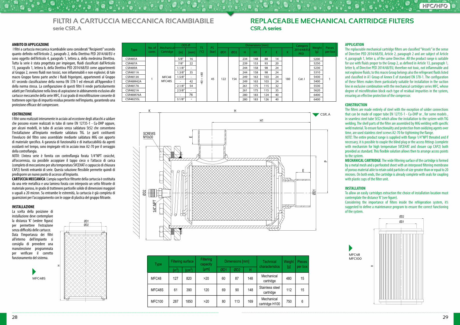
28 29
HFC/HFOHFC/HFO
FILTRI A CARTUCCIA MECCANICA RICAMBIABILE REPLACEABLE MECHANICAL CARTRIDGE FILTERSserie CSR..A CSR..A series
[in] [mm] ØD1 ØD2 H H1 P E K
CSR485A 5/8" 16 234 148 88 14 5200CSR487A 7/8" 22 239 153 93 20 5250CSR489A 1.1/8" - 244 158 98 24 5230CSR4811A 1.3/8" 35 244 158 98 24 5310CSR4813A 1.5/8" - 249 163 103 24 5430CSR48M42A - 42 249 163 103 24 5400CSR4817A 2.1/8" 54 261 175 115 32 5530CSR4821A 2.5/8" - 261 175 115 35 5620
3.1/8" -280 183 124 40 6400- M76280 183 126 40 6400
11 MFC48 MFC48S
Cat. I18045
-40
÷ +8
0
122 154
Pieces per box
TypeNo. of cores
Mechanical Cartridge
ODS ØTS [°C]
PS [bar]
Dimensions [mm] Category 2014/68/EU
PED
Weight [g]
CSR4825SLCSR48M76
[in2] [cm2] ØD1 ØD2 H
MFC48 127 820 >20 60 87 148 Mechanical cartridge 480 15
MFC48S 61 390 120 69 90 148 Stainless steel cartridge 112 15
MFC100 287 1850 >20 80 113 169 Mechanical cartridge H100 750 6
Filtering capacity
[µm]Type
Filtering surface Dimensions [mm] Technical characteristics
Pieces per box
Weight [g]
AMBITO DI APPLICAZIONE I filtri a cartuccia meccanica ricambiabile sono considerati “Recipienti” secondo quanto definito nell’Articolo 2, paragrafo 2, della Direttiva PED 2014/68/EU e sono oggetto dell’Articolo 4, paragrafo 1, lettera a, della medesima Direttiva. Tutta la serie è stata progettata per impiegare, fluidi classificati dall’Articolo 13, paragrafo 1, lettera b, della Direttiva PED 2014/68/EU come appartenenti al Gruppo 2, ovvero fluidi non tossici, non infiammabili e non esplosivi; di tale macro Gruppo fanno parte anche i fluidi frigorigeni, appartenenti al Gruppo A1 secondo classificazione della norma EN 378-1 ed elencati all’Appendice E della norma stessa. La configurazione di questi filtri li rende particolarmente adatti per l’installazione nella linea di aspirazione in abbinamento esclusivo alle cartucce meccaniche della serie MFC, il cui grado di microfiltrazione consente di trattenere ogni tipo di impurità residua presente nell’impianto, garantendo una protezione efficace del compressore.
COSTRUZIONEI filtri sono realizzati interamente in acciaio ad eccezione degli attacchi a saldare che possono essere realizzati in tubo di rame EN 12735-1 - Cu-DHP oppure, per alcuni modelli, in tubo di acciaio senza saldatura St52 che consentono l’installazione all’impianto mediante saldatura TIG. Le parti costituenti l’involucro del filtro sono assemblate mediante saldatura MIG con apporto di materiale specifico. A garanzia di funzionalità e di inattaccabilità da agenti ossidanti nel tempo, sono impiegate viti in acciaio inox A2-70 per il serraggio della controflangia.NOTA: L’intera serie è fornita con controflangia forata 1/4“NPT cosicché, all’occorrenza, sia possibile accoppiare il tappo cieco o l’attacco di carica (completo di meccanismo per alta temperatura SVCEHAT e cappuccio di chiusura CAP2) forniti entrambi di serie. Questa soluzione flessibile permette quindi di predisporre un nuovo punto di accesso all’impianto.CARTUCCIA MECCANICA: L’ampia superficie filtrante della cartuccia è costituita da una rete metallica e una lamiera forata con interposto un setto filtrante di materiale poroso, in grado di trattenere particelle solide di dimensioni maggiori o uguali a 20 micron. Su entrambe le estremità, la cartuccia è già completa di guarnizioni per l’accoppiamento con le coppe di plastica del gruppo filtrante.
INSTALLAZIONELa scelta della posizione di installazione deve contemplare la distanza ‘K’ (vedere figura) per permettere l’estrazione senza difficoltà delle cartucce.Data l’importanza dei filtri all’interno dell’impianto si consiglia di prevedere una manutenzione programmata per verificare il corretto funzionamento del sistema.
APPLICATIONThe replaceable mechanical cartridge filters are classified “Vessels” in the sense of Directive PED 2014/68/EU, Article 2, paragraph 2 and are subject of Article 4, paragraph 1, letter a, of the same Directive. All the product range is suitable for use with fluids proper to the Group 2, as defined in Article 13, paragraph 1, letter b, of Directive PED 2014/68/EU, therefore not toxic, not inflammable and not explosive fluids; to this macro Group belongs also the refrigerant fluids listed and classified in A1 Group of Annex E of standard EN 378-1. The configuration of these filters makes them particularly suitable for installation in the suction line in exclusive combination with the mechanical cartridges series MFC, whose degree of microfiltration block each type of residual impurities in the system, ensuring an effective protection of the compressor.
CONSTRUCTIONThe filters are made entirely of steel with the exception of solder connections that can be made of copper tube EN 12735-1 - Cu-DHP or , for some models , in seamless steel tube St52 which allow the installation to the system with TIG welding. The shell parts of the filter are assembled by MIG welding with specific weld material. To ensure functionality and protection from oxidizing agents over time, are used stainless steel screws A2-70 for tightening the flange.NOTE: The entire product range is supplied with flange 1/4”NPT threated and if necessary, it is possible to couple the blind plug or the access fittings (complete with mechanism for high temperature SVCEHAT and closure cap CAP2) both provided as standard. This flexible solution allows then to arrange access points to the system.MECHANICAL CARTRIDGE: The wide filtering surface of the cartridge is formed by a metal mesh and a perforated sheet with an interposed filtering membrane of porous material able to retain solid particles of size greater than or equal to 20 microns. On both ends, the cartridge is already complete with seals for coupling with plastic cups of the filter unit.
INSTALLATIONTo allow an easily cartridges extraction the choice of installation location must contemplate the distance ‘K’ (see figure).Considering the importance of filters inside the refrigeration system, it’s suggested to define a maintenance program to ensure the correct functioning of the system.
MFC48S
MFC48MFC100
H1
E
P
E
K
ØD2 ØD
1
H
1/4"
NPT
SCREWSM10x30
CSR..A
ØD1ØD2
H H
ØD2
ØD1
-A 76

30 31
HFC/HFOHFC/HFO
INDICATORI DI LIQUIDOE DI UMIDITA’
INDICATORIINDICATORS
LIQUID AND MOISTURE INDICATORS
serie LI - MI LI - MI seriesAMBITO DI APPLICAZIONEGli indicatori sono considerati “Accessori a pressione” secondo quanto definito nell’Articolo 2, paragrafo 5, della Direttiva PED 2014/68/EU e sono oggetto dell’Articolo 4, paragrafo 1, lettera c, della medesima Direttiva. Tutta la serie è stata progettata per l’utilizzo con fluidi classificati dall’Articolo 13, paragrafo 1, lettera b, della Direttiva PED 2014/68/EU come appartenenti al Gruppo 2, ovvero fluidi non tossici, non infiammabili e non esplosivi; di tale macro Gruppo fanno parte anche i fluidi frigorigeni, appartenenti al Gruppo A1 secondo classificazione della norma EN 378-1 ed elencati all’Appendice E della norma stessa. Gli indicatori a sella sono esclusi dal campo d’applicazione della Direttiva 2014/68/EU in quanto componenti di tubazione.La Funzione degli indicatori di liquido e di umidità, è quella di verificare in tempo reale la regolarità del flusso e la presenza di umidità nel sistema. COSTRUZIONEGli indicatori sono realizzati incastonando una spia di vetro direttamente nel corpo di ottone forgiato a caldo EN 12420 – CW617N oppure nella ghiera indicatrice in ottone EN 12164 – CW614N. Si forma così un’unica struttura compatta che riduce al minimo le giunzioni fra componenti, con conseguente eliminazione di possibili fughe di refrigerante. Per ottenere una perfetta tenuta del vetro in tutti gli indicatori viene utilizzata una guarnizione in teflon modificato, negli indicatori a sella la tenuta tra ghiera indicatrice e corpo è affidata ad un OR in gomma CR o HNBR. I modelli che si collegano all’impianto mediante saldobrasatura, hanno attacchi in rame EN 12735-1 - Cu-DHP. SERIE LI: Questa serie di indicatori permette di verificare se in condizioni di carica o di funzionamento dell’impianto il fluido refrigerante transita nell’indicatore in stato completamente liquido. La presenza di bollicine indica una parziale evaporazione del fluido lungo la linea del liquido.SERIE MI: Questa serie di indicatori è caratterizzata da un elemento sensibile all’umidità, il cui colore vira dal verde al giallo a seconda della concentrazione di umidità nell’impianto. INSTALLAZIONEAll’avviamento dell’impianto il colore dell’elemento sensibile all’umidità può essere giallo, sia a causa dell’umidità atmosferica con cui l’indicatore è venuto a contatto, sia a causa dell’umidità presente nel circuito. Quando il grado d’umidità del frigorigeno si normalizza grazie all’azione del filtro disidratatore, il colore dell’elemento ritorna ad essere verde.Il collegamento degli indicatori all’impianto deve essere eseguito con una lega a basso punto di fusione. Durante la saldatura evitare di dirigere la fiamma direttamente verso il corpo tenendo quest’ultimo raffreddato per evitare di compromettere la tenuta della guarnizione tra vetro e corpo d’ottone.NOTA: Dove è necessario serrare la ghiera indicatrice (provvista di anello di tenuta) al corpo indicatore, utilizzare la coppia indicata nelle istruzioni d’uso allegate al prodotto al fine di garantire una perfetta tenuta e resistenza alla PS massima ammissibile dichiarata.
APPLICATIONThe indicators are classified “Pressure accessories” in the sense of the Directive PED 2014/68/EU, Article 2, paragraph 5 and are subject of Article 4, paragraph 1, letter c, of the same Directive. All the product range is suitable for use with fluids proper to the Group 2, as defined in Article 13, paragraph 1, letter b, of Directive PED 2014/68/EU, therefore not toxic, not inflammable and not explosive fluids; to this macro Group belongs also the refrigerant fluids listed and classified in A1 Group of Annex E of standard EN 378-1. Saddle type indicators are excluded from the scope of Directive 2014/68/EU as piping components. The function of liquid and moisture indicators, is to verify the actual situation of flow and the presence of moisture in the system.
CONSTRUCTIONThe indicators are made by embedding a spy glass directly into the body of hot forged brass EN 12420 - CW617N or in the annular indicator body of brass EN 12164 - CW614N. This forms a unique compact structure that minimizes the junctions between components, followed by removing of possible leakage of refrigerant. To obtain a perfect sealing of glass in all indicators is used a modified Teflon gasket, in saddle type indicators the seal between the annular indicator and the body is done by an O-ring made of CR or HNBR . In some models, the solder connections are made of copper EN 12735-1 - Cu-DHP.
LI SERIES: This indicators series allows to check if the fluid passes in the indicator in the completely liquid state in charging conditions or in normal system operation. The presence of bubbles indicates the partial evaporation of the fluid along the liquid line.MI SERIES: This indicators series is characterized by an element sensitive to moisture which changes color from green to yellow depending on the concentration of moisture in the system.
INSTALLATIONDuring the first start, the color of the element sensitive to moisture can be yellow, not only because of atmospheric moisture with which the indicator has come into contact, but also for presence of moisture in the circuit. When the moisture content of the refrigerant is normalized through the dehydrator filter, the color of the element become green. The brazing of the indicators to the system shall be done with a low melting point alloy. During this process do not point the flame directly towards the body keeping it cooled in order to avoid compromising the seal of the gaskets.NOTE: Where it is necessary to tighten the ring nut (equipped with a seal) to the body indicator, use the torque specified in the instructions provided with the product in order to ensure a perfect seal and resistance to PS maximum
allowable declared.
Green / Dry Intermediate color Yellow / Wet Green / Dry Intermediate color Yellow / WetR22 < 30 30 - 120 > 120 < 60 60 - 240 > 240R134a < 30 30 - 100 > 100 < 55 55 - 180 > 180R404A < 20 20 - 70 > 70 < 30 30 - 120 > 120R407C < 30 30 - 110 > 110 < 60 60 - 240 > 240R410A < 30 30 - 150 > 150 < 60 60 - 300 > 300R507 < 20 20 - 65 > 65 < 30 30 - 120 > 120
MOISTURE CONTENT [ppm] - LIQUID PHASE
Liquid temperature: +25 °CFluid
Liquid temperature: +50 °C

32 33
HFC/HFOHFC/HFO
INDICATORI DI LIQUIDO LIQUID INDICATORSserie LI LI series
LI..MF
LI..MM
[in] [mm] [in] [mm] [in] [mm] ØD L H H1 CH
LI2MM 1/4" - - - - - - 70 22,5 8 14 120 25LI3MM 3/8" - - - - - - 75 190 25LI4MM 1/2" - - - - - - 80 204 25LI5MM 5/8" - - - - - - 88 31,5 13 24 255 25LI6MM 3/4" - - - - - - 91 35,5 15 28 325 25LI2MF 1/4" - - - - - - 70 209 25LI3MF 3/8" - - - - - - 75 202 25LI4MF 1/2" - - - - - - 80 31,5 13 24 235 25LI5MF 5/8" - - - - - - 85 35,5 15 28 305 25LI6MF 3/4" - - - - - - 94 41,5 17,5 35 471 25LI2SL - - - 1/4" 6 - - 202 7 22,5 - 130 35
LI2SLP - - - 1/4" 6 - - 98,5 38 58,5 - 130 32LI2S - 1/4" - - - - - 126 50LI3S - 3/8" - - - - - 132 50LIM10S - - 10 - - - - 133 50LIM12S - - 12 - - - - 203 50LI4S - 1/2" - - - - - 205 50LI5S - 5/8" 16 - - - - 198 50LIM18S - - 18 - - - - 235 50LI6S - 3/4" - - - - - 237 50LI7S - 7/8" 22 - - - - 155 35,5 15 28 309 42LI9S - 1.1/8" 28 - - - - 183 41,5 17,5 35 510 42LIM28SCU - - - - 28 - - 150 30 - 235 228 26LI11S - - - 1.3/8" 35 - - - - 275 26LI11ST - 1.3/8" 35 - - - - - - 283 26LI13S - - - 1.5/8" - - - - - 425 26LI13ST - 1.5/8" - - - - - - - 425 26LIM42S - - - - 42 - - - - 425 26LI17ST - 2.1/8 54 - - - - 42 - - 540 26LI5T - - - - - 5/8" 16 - 36 - 120 25LIM18T - - - - - - 18 - 37 - 120 25LI7T - - - - - 7/8" 22 - 39 - 120 25LI9T - - - - - 1.1/8" 28 - 42 - 120 25LI11T - - - - - 1.3/8" 35 - 45 - 120 25LIM42T - - - - - 1.5/8" 42 - 48,5 - 120 25LI17T - - - - - 2.1/8" 54 - 56 - 120 25
Type Type of connection
Art. 4.3
22
13 24
8 14
12 22
2212132
14531,5
29,5
29,5
-30 ÷
+80
45
32
Cat. I
32 Excluded
17037
Male-
male
Male-
female
160
Pieces per box
Category 2014/68/EU
PED
SAE Flare
ODS Ø ODM Ø For pipe Ø TS [°C]
PS [bar]
Dimensions [mm] Weight [g]
29,5 12
125Sa
ddle
Hot f
orge
d bra
ss
33,5
Copp
er tu
beBy
-pas
s
36
Solde
ring
22,5
LI..ST LI..SLI..SCU LI..SLP
LI..SL
LI..S
LI..T
ØD
H
L23
14,5
H1
ØD
L
H1
H
L
H1
H
ØD
ØD
H1
H
L
L
H
H
ØD
H1
H
L
H
ØD
L
ØD
ØD
CH
CH
CH
ØD
H
L23
14,5
H1
ØD
L
H1
H
L
H1
H
ØD
ØD
H1
H
L
L
H
H
ØD
H1
H
L
H
ØD
L
ØD
ØD
CH
CH
CH
ØD
H
L23
14,5
H1
ØD
L
H1
H
L
H1
H
ØD
ØD
H1
H
L
L
H
H
ØD
H1
H
L
H
ØD
L
ØD
ØD
CH
CH
CH
ØD
H
L23
14,5
H1
ØD
L
H1
H
L
H1
H
ØD
ØD
H1
H
L
L
H
H
ØD
H1
H
L
H
ØD
L
ØD
ØD
CH
CH
CH
ØD
H
L23
14,5
H1
ØD
L
H1
H
L
H1
H
ØD
ØDH1
H
L
L
H
H
ØDH1
H
L
H
ØD
L
ØD
ØD
CH
CH
CH
ØD
H
L23
14,5
H1
ØD
L
H1
H
L
H1
H
ØD
ØD
H1
H
L
L
H
H
ØD
H1
H
L
H
ØD
L
ØD
ØD
CH
CH
CH
ØD
H
L23
14,5
H1
ØD
L
H1
H
L
H1
H
ØD
ØD
H1
H
L
L
H
H
ØD
H1
H
L
H
ØD
L
ØD
ØD
CH
CH
CH
ØD
H
L23
14,5
H1
ØD
L
H1
H
L
H1
H
ØD
ØD
H1
H
L
L
H
H
ØD
H1
H
L
H
ØD
L
ØD
ØD
CH
CH
CH
-40 ÷
+12
0
43
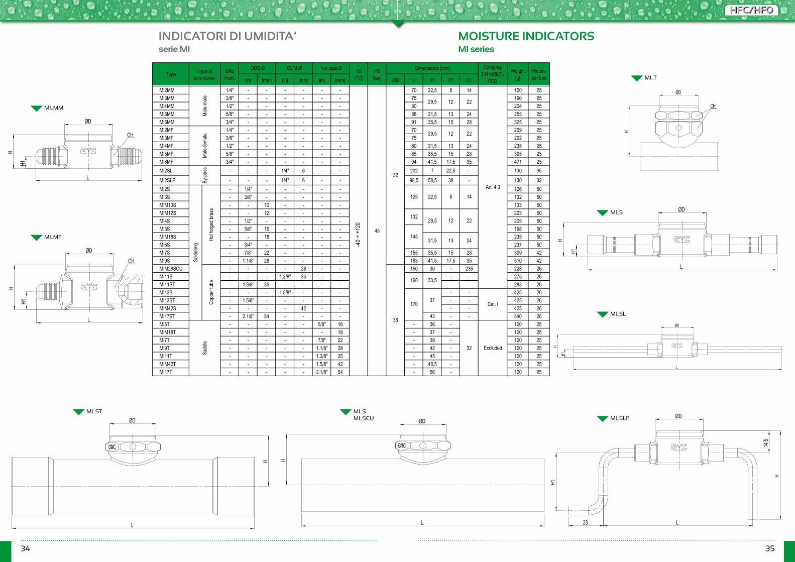
34 35
HFC/HFOHFC/HFO
INDICATORI DI UMIDITA’ MOISTURE INDICATORSserie MI MI series
MI..MF
MI..MM
[in] [mm] [in] [mm] [in] [mm] ØD L H H1 CH
MI2MM 1/4" - - - - - - 70 22,5 8 14 120 25MI3MM 3/8" - - - - - - 75 190 25MI4MM 1/2" - - - - - - 80 204 25MI5MM 5/8" - - - - - - 88 31,5 13 24 255 25MI6MM 3/4" - - - - - - 91 35,5 15 28 325 25MI2MF 1/4" - - - - - - 70 209 25MI3MF 3/8" - - - - - - 75 202 25MI4MF 1/2" - - - - - - 80 31,5 13 24 235 25MI5MF 5/8" - - - - - - 85 35,5 15 28 305 25MI6MF 3/4" - - - - - - 94 41,5 17,5 35 471 25MI2SL - - - 1/4" 6 - - 202 7 22,5 - 130 35
MI2SLP - - - 1/4" 6 - - 98,5 58,5 38 - 130 32MI2S - 1/4" - - - - - 126 50MI3S - 3/8" - - - - - 132 50MIM10S - - 10 - - - - 133 50MIM12S - - 12 - - - - 203 50MI4S - 1/2" - - - - - 205 50MI5S - 5/8" 16 - - - - 198 50MIM18S - - 18 - - - - 235 50MI6S - 3/4" - - - - - 237 50MI7S - 7/8" 22 - - - - 155 35,5 15 28 309 42MI9S - 1.1/8" 28 - - - - 183 41,5 17,5 35 510 42MIM28SCU - - - - 28 - - 150 30 - 235 228 26MI11S - - - 1.3/8" 35 - - - - 275 26MI11ST - 1.3/8" 35 - - - - - - 283 26MI13S - - - 1.5/8" - - - - - 425 26MI13ST - 1.5/8" - - - - - - - 425 26MIM42S - - - - 42 - - - - 425 26MI17ST - 2.1/8" 54 - - - - 42 - - 540 26MI5T - - - - - 5/8" 16 - 36 - 120 25MIM18T - - - - - - 18 - 37 - 120 25MI7T - - - - - 7/8" 22 - 39 - 120 25MI9T - - - - - 1.1/8" 28 - 42 - 120 25MI11T - - - - - 1.3/8" 35 - 45 - 120 25MIM42T - - - - - 1.5/8" 42 - 48,5 - 120 25MI17T - - - - - 2.1/8" 54 - 56 - 120 25
Pieces per box
Category 2014/68/EU
PED
Weight [g]
ODS Ø ODM Ø For pipe Ø TS [°C]
PS [bar]
36
29,5
31,5
Solde
ring
160
-30 ÷
+80
45
33,5
125
Copp
er tu
be
37
29,5
Sadd
le
32
Cat. I
32 Excluded
170
Art. 4.3
12132
29,5
22,5
14513
22
22
8
12
12
14
22
Type Type of connection
24
Male-
male
Male-
female
By-p
ass
Hot fo
rged
bras
s
SAE Flare
Dimensions [mm]
MI..ST MI..SMI..SCU MI..SLP
MI..SL
MI..S
MI..T
ØD
H
L23
14,5
H1
ØD
L
H1
H
L
H1
H
ØD
ØD
H1
H
L
L
H
H
ØD
H1
H
L
H
ØD
L
ØD
ØD
CH
CH
CH
ØD
H
L23
14,5
H1
ØD
L
H1
H
L
H1
H
ØD
ØD
H1
H
L
L
H
H
ØD
H1
H
L
H
ØD
L
ØD
ØD
CH
CH
CH
ØDH
L23
14,5
H1
ØD
L
H1
H
L
H1
H
ØD
ØD
H1
H
L
L
H
H
ØD
H1
H
L
H
ØD
L
ØD
ØD
CH
CH
CH
ØD
H
L23
14,5
H1
ØD
L
H1
H
L
H1
H
ØD
ØD
H1
H
L
L
H
H
ØD
H1
H
L
H
ØD
L
ØD
ØD
CH
CH
CH
ØD
H
L23
14,5
H1
ØD
L
H1
H
L
H1
H
ØD
ØD
H1
H
L
L
H
H
ØD
H1
H
L
H
ØD
L
ØD
ØD
CH
CH
CH
ØD
H
L23
14,5
H1
ØD
L
H1
H
L
H1
H
ØD
ØD
H1
H
L
L
H
H
ØD
H1
H
L
H
ØD
L
ØD
ØD
CH
CH
CH
ØD
H
L23
14,5
H1
ØD
L
H1
H
L
H1
H
ØD
ØD
H1
H
L
L
H
H
ØD
H1
H
L
H
ØD
L
ØD
ØD
CH
CH
CH
ØD
H
L23
14,5
H1
ØD
L
H1
H
L
H1
H
ØD
ØD
H1
H
L
L
H
H
ØD
H1
H
L
H
ØD
L
ØD
ØD
CH
CH
CH
-40 ÷
+12
0
43
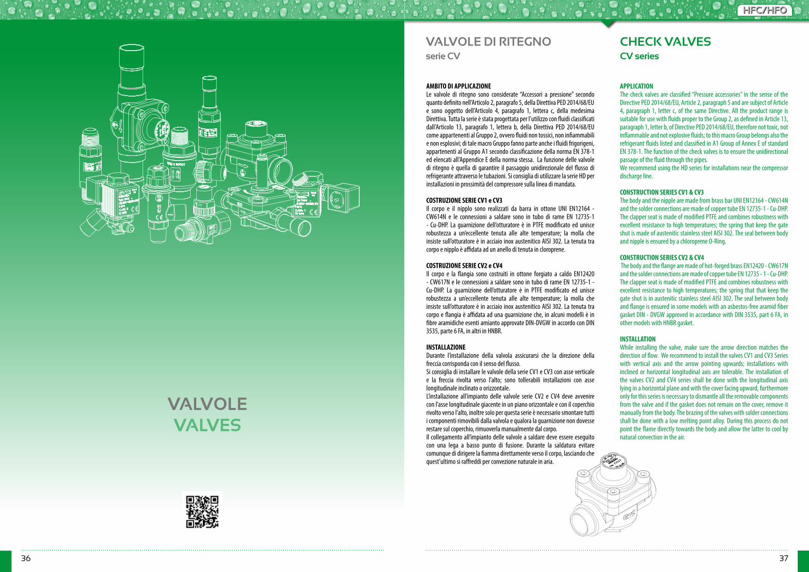
36 37
HFC/HFOHFC/HFO
VALVOLE DI RITEGNO
VALVOLEVALVES
CHECK VALVESserie CV CV series
AMBITO DI APPLICAZIONELe valvole di ritegno sono considerate “Accessori a pressione” secondo quanto definito nell’Articolo 2, paragrafo 5, della Direttiva PED 2014/68/EU e sono oggetto dell’Articolo 4, paragrafo 1, lettera c, della medesima Direttiva. Tutta la serie è stata progettata per l’utilizzo con fluidi classificati dall’Articolo 13, paragrafo 1, lettera b, della Direttiva PED 2014/68/EU come appartenenti al Gruppo 2, ovvero fluidi non tossici, non infiammabili e non esplosivi; di tale macro Gruppo fanno parte anche i fluidi frigorigeni, appartenenti al Gruppo A1 secondo classificazione della norma EN 378-1 ed elencati all’Appendice E della norma stessa. La funzione delle valvole di ritegno è quella di garantire il passaggio unidirezionale del flusso di refrigerante attraverso le tubazioni. Si consiglia di utilizzare la serie HD per installazioni in prossimità del compressore sulla linea di mandata. COSTRUZIONE SERIE CV1 e CV3Il corpo e il nipplo sono realizzati da barra in ottone UNI EN12164 - CW614N e le connessioni a saldare sono in tubo di rame EN 12735-1 - Cu-DHP. La guarnizione dell’otturatore è in PTFE modificato ed unisce robustezza a un’eccellente tenuta alle alte temperature; la molla che insiste sull’otturatore è in acciaio inox austenitico AISI 302. La tenuta tra corpo e nipplo è affidata ad un anello di tenuta in cloroprene.
COSTRUZIONE SERIE CV2 e CV4 Il corpo e la flangia sono costruiti in ottone forgiato a caldo EN12420 - CW617N e le connessioni a saldare sono in tubo di rame EN 12735-1 - Cu-DHP. La guarnizione dell’otturatore è in PTFE modificato ed unisce robustezza a un’eccellente tenuta alle alte temperature; la molla che insiste sull’otturatore è in acciaio inox austenitico AISI 302. La tenuta tra corpo e flangia è affidata ad una guarnizione che, in alcuni modelli è in fibre aramidiche esenti amianto approvate DIN-DVGW in accordo con DIN 3535, parte 6 FA, in altri in HNBR.
INSTALLAZIONEDurante l’installazione della valvola assicurarsi che la direzione della freccia corrisponda con il senso del flusso.Si consiglia di installare le valvole della serie CV1 e CV3 con asse verticale e la freccia rivolta verso l’alto; sono tollerabili installazioni con asse longitudinale inclinato o orizzontale. L’installazione all’impianto delle valvole serie CV2 e CV4 deve avvenire con l’asse longitudinale giacente in un piano orizzontale e con il coperchio rivolto verso l’alto, inoltre solo per questa serie è necessario smontare tutti i componenti rimovibili dalla valvola e qualora la guarnizione non dovesse restare sul coperchio, rimuoverla manualmente dal corpo. Il collegamento all’impianto delle valvole a saldare deve essere eseguito con una lega a basso punto di fusione. Durante la saldatura evitare comunque di dirigere la fiamma direttamente verso il corpo, lasciando che quest’ultimo si raffreddi per convezione naturale in aria.
APPLICATIONThe check valves are classified “Pressure accessories” in the sense of the Directive PED 2014/68/EU, Article 2, paragraph 5 and are subject of Article 4, paragraph 1, letter c, of the same Directive. All the product range is suitable for use with fluids proper to the Group 2, as defined in Article 13, paragraph 1, letter b, of Directive PED 2014/68/EU, therefore not toxic, not inflammable and not explosive fluids; to this macro Group belongs also the refrigerant fluids listed and classified in A1 Group of Annex E of standard EN 378-1. The function of the check valves is to ensure the unidirectional passage of the fluid through the pipes.We recommend using the HD series for installations near the compressor discharge line.
CONSTRUCTION SERIES CV1 & CV3The body and the nipple are made from brass bar UNI EN12164 - CW614N and the solder connections are made of copper tube EN 12735-1 - Cu-DHP. The clapper seat is made of modified PTFE and combines robustness with excellent resistance to high temperatures; the spring that keep the gate shut is made of austenitic stainless steel AISI 302. The seal between body and nipple is ensured by a chloroprene O-Ring.
CONSTRUCTION SERIES CV2 & CV4 The body and the flange are made of hot-forged brass EN12420 - CW617N and the solder connections are made of copper tube EN 12735 - 1 - Cu-DHP. The clapper seat is made of modified PTFE and combines robustness with excellent resistance to high temperatures; the spring that that keep the gate shut is in austenitic stainless steel AISI 302. The seal between body and flange is ensured in some models with an asbestos-free aramid fiber gasket DIN - DVGW approved in accordance with DIN 3535, part 6 FA, in other models with HNBR gasket.
INSTALLATIONWhile installing the valve, make sure the arrow direction matches the direction of flow. We recommend to install the valves CV1 and CV3 Series with vertical axis and the arrow pointing upwards; installations with inclined or horizontal longitudinal axis are tolerable. The installation of the valves CV2 and CV4 series shall be done with the longitudinal axis lying in a horizontal plane and with the cover facing upward, furthermore only for this series is necessary to dismantle all the removable components from the valve and if the gasket does not remain on the cover, remove it manually from the body. The brazing of the valves with solder connections shall be done with a low melting point alloy. During this process do not point the flame directly towards the body and allow the latter to cool by natural convection in the air.
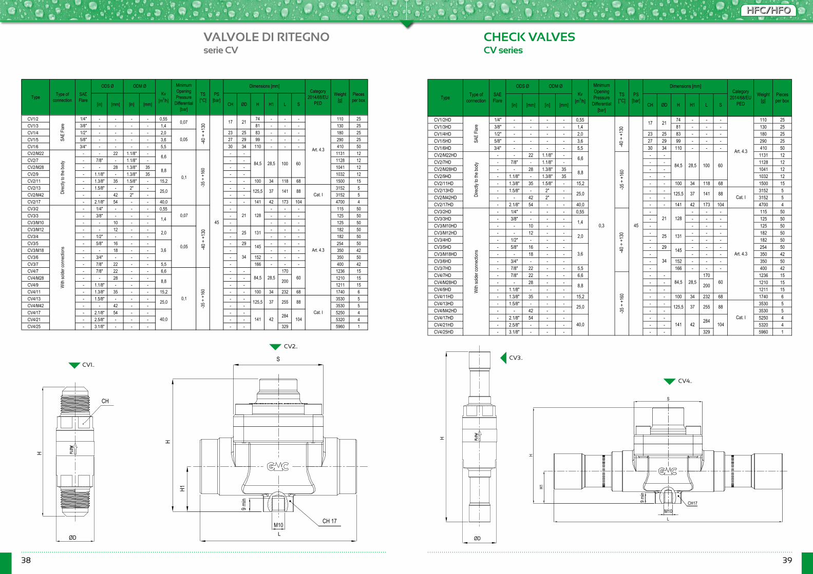
38 39
HFC/HFOHFC/HFO
VALVOLE DI RITEGNO CHECK VALVESserie CV CV series
CV1..CV3..
CV2..
CV4..
[in] [mm] [in] [mm] CH ØD H H1 L S
CV1/2 1/4" - - - - 0,55 74 - - - 110 25CV1/3 3/8" - - - - 1,4 81 - - - 130 25CV1/4 1/2" - - - - 2,0 23 25 83 - - - 180 25CV1/5 5/8" - - - - 3,6 27 29 99 - - - 290 25CV1/6 3/4" - - - - 5,5 30 34 110 - - - 410 50CV2/M22 - - 22 1.1/8" - - - 1131 12CV2/7 - 7/8" - 1.1/8" - - - 1128 12CV2/M28 - - 28 1.3/8" 35 - - 1041 12CV2/9 - 1.1/8" - 1.3/8" 35 - - 1032 12CV2/11 - 1.3/8" 35 1.5/8" - 15,2 - - 100 34 118 68 1500 15CV2/13 - 1.5/8" - 2" - - - 3152 5CV2/M42 - - 42 2" - - - 3152 5CV2/17 - 2.1/8" 54 - - 40,0 - - 141 42 173 104 4700 4CV3/2 - 1/4" - - - 0,55 - - - - 115 50CV3/3 - 3/8" - - - - - - - 125 50CV3/M10 - - 10 - - - - - - 125 50CV3/M12 - - 12 - - - - - - 182 50CV3/4 - 1/2" - - - - - - - 182 50CV3/5 - 5/8" 16 - - - 29 - - - 254 50CV3/M18 - - 18 - - - - - - 350 42CV3/6 - 3/4" - - - - 152 - - - 350 50CV3/7 - 7/8" 22 - - 5,5 - 166 - - - 400 42CV4/7 - 7/8" 22 - - 6,6 - - 170 1236 15CV4/M28 - - 28 - - - - 1210 15CV4/9 - 1.1/8" - - - - - 1211 15CV4/11 - 1.3/8" 35 - - 15,2 - - 100 34 232 68 1740 6CV4/13 - 1.5/8" - - - - - 3530 5CV4/M42 - - 42 - - - - 3530 5CV4/17 - 2.1/8" 54 - - - - 5250 4CV4/21 - 2.5/8" - - - - - 5320 4CV4/25 - 3.1/8" - - - - - 329 5960 1
Pieces per box
Art. 4.3
Art. 4.3
Type Type of connection
Kv [m3/h]
MinimumOpeningPressure
Differential[bar]
PS [bar]
SAE Flare
17
With
solde
r con
necti
ons
0,07
-50 ÷
+14
0
Category 2014/68/EU
PED
Weight [g]
21
0,05
Dire
ctly t
o the
body
6,6
0,1
-35 ÷
+16
0
SAE
Flare
0,07
-50 ÷
+14
0
45
84,5 28,5 100 608,8
25,0 125,5 37 141 88
21 1281,4
2,0
0,05
25 131
3,6
60
141 42284
104
Cat. I
200
25,0 125,5 37 2550,1
-35 ÷
+16
0
84,5 28,5
ODS Ø ODM Ø Dimensions [mm]
88
Cat. I40,0
TS [°C]
34
145
8,8
[in] [mm] [in] [mm] CH ØD H H1 L S
CV1/2HD 1/4" - - - - 0,55 74 - - - 110 25CV1/3HD 3/8" - - - - 1,4 81 - - - 130 25CV1/4HD 1/2" - - - - 2,0 23 25 83 - - - 180 25CV1/5HD 5/8" - - - - 3,6 27 29 99 - - - 290 25CV1/6HD 3/4" - - - - 5,5 30 34 110 - - - 410 50CV2/M22HD - - 22 1.1/8" - - - 1131 12CV2/7HD - 7/8" - 1.1/8" - - - 1128 12CV2/M28HD - - 28 1.3/8" 35 - - 1041 12CV2/9HD - 1.1/8" - 1.3/8" 35 - - 1032 12CV2/11HD - 1.3/8" 35 1.5/8" - 15,2 - - 100 34 118 68 1500 15CV2/13HD - 1.5/8" - 2" - - - 3152 5CV2/M42HD - - 42 2" - - - 3152 5CV2/17HD - 2.1/8" 54 - - 40,0 - - 141 42 173 104 4700 4CV3/2HD - 1/4" - - - 0,55 - - - - 115 50CV3/3HD - 3/8" - - - - - - - 125 50CV3/M10HD - - 10 - - - - - - 125 50CV3/M12HD - - 12 - - - - - - 182 50CV3/4HD - 1/2" - - - - - - - 182 50CV3/5HD - 5/8" 16 - - - 29 - - - 254 50CV3/M18HD - - 18 - - - - - - 350 42CV3/6HD - 3/4" - - - - 152 - - - 350 50CV3/7HD - 7/8" 22 - - 5,5 - 166 - - - 400 42CV4/7HD - 7/8" 22 - - 6,6 - - 170 1236 15CV4/M28HD - - 28 - - - - 1210 15CV4/9HD - 1.1/8" - - - - - 1211 15CV4/11HD - 1.3/8" 35 - - 15,2 - - 100 34 232 68 1740 6CV4/13HD - 1.5/8" - - - - - 3530 5CV4/M42HD - - 42 - - - - 3530 5CV4/17HD - 2.1/8" 54 - - - - 5250 4CV4/21HD - 2.5/8" - - - - - 5320 4CV4/25HD - 3.1/8" - - - - - 329 5960 1
Pieces per box
TS [°C]
Art. 4.3
Art. 4.3
Type Type of connection
Kv [m3/h]
MinimumOpeningPressure
Differential[bar]
PS [bar]
17
With
solde
r con
necti
ons -5
0 ÷ +
140
-35 ÷
+16
0
Category 2014/68/EU
PED
Weight [g]
SAE Flare
21
Dire
ctly t
o the
body
6,6
-35 ÷
+16
0
84,5
145
34
SAE
Flare
0,3
-50 ÷
+14
0
28,5 100 608,8
25,0 125,5 37 141 88
45
Cat. I
21 1281,4
2,0 25 131
3,6
28,5 608,8 200
25,0 125,5 37 255 88
ODS Ø ODM Ø Dimensions [mm]
Cat. I40,0 141 42
284104
84,5
H1
L
H
S
CH17
M10
9 min
ØD
H
H
ØD
CH
H1
S
H
L
CH 17M10
9 min
-40 ÷
+13
0-4
0 ÷ +
130
-40 ÷
+13
0-4
0 ÷ +
130
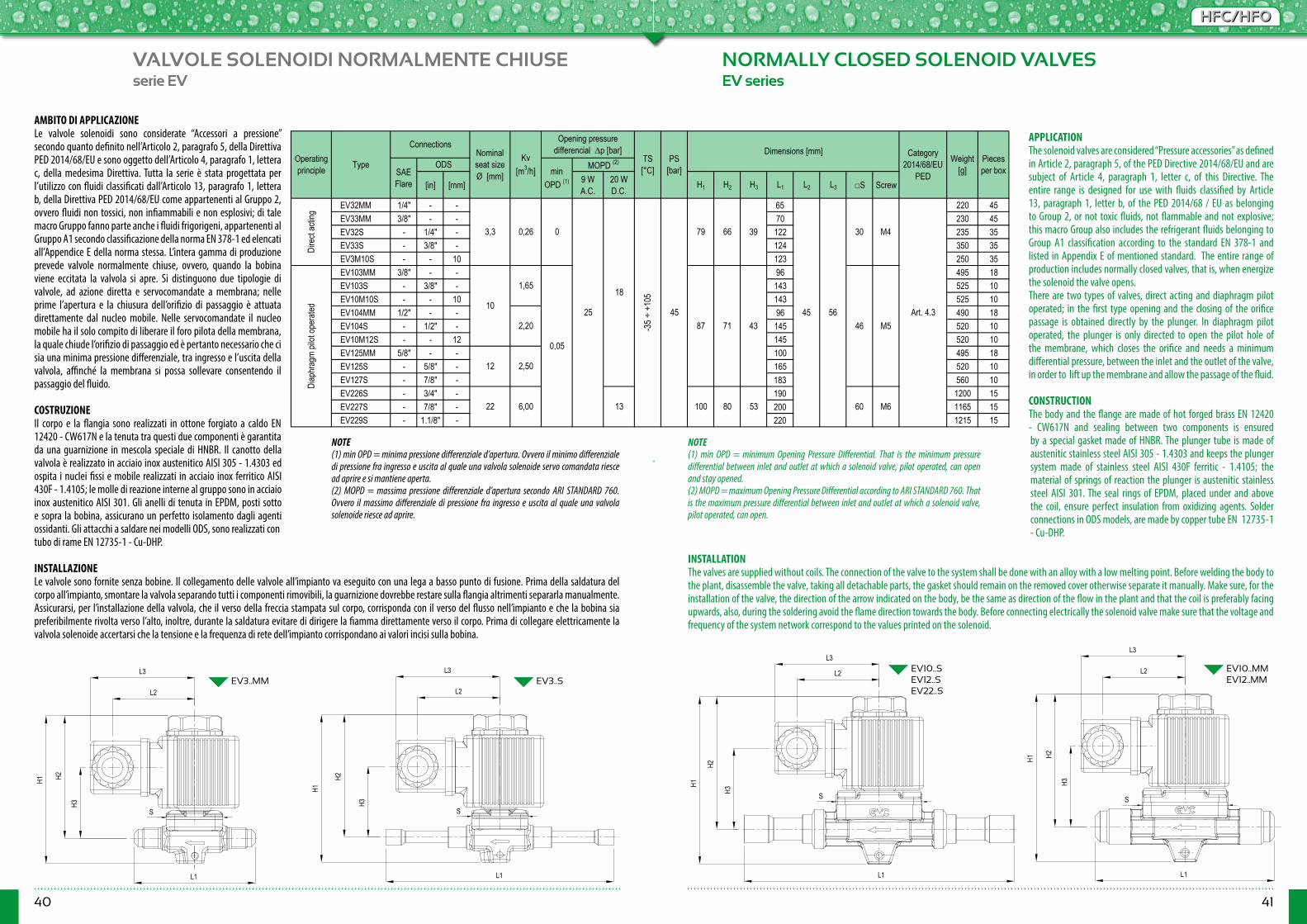
40 41
HFC/HFOHFC/HFO
VALVOLE SOLENOIDI NORMALMENTE CHIUSE NORMALLY CLOSED SOLENOID VALVESserie EV EV series
EV3..MM EV3..S EV10..S EV12..S EV22..S
EV10..MMEV12..MM
[in] [mm] 9 W A.C.
20 W D.C.
H1 H2 H3 L1 L2 L3 □S Screw
EV32MM 1/4" - - 65 220 45EV33MM 3/8" - - 70 230 45EV32S - 1/4" - 122 235 35EV33S - 3/8" - 124 350 35EV3M10S - - 10 123 250 35EV103MM 3/8" - - 96 495 18EV103S - 3/8" - 143 525 10EV10M10S - - 10 143 525 10EV104MM 1/2" - - 96 490 18EV104S - 1/2" - 145 520 10EV10M12S - - 12 145 520 10EV125MM 5/8" - - 100 495 18EV125S - 5/8" - 165 520 10EV127S - 7/8" - 183 560 10EV226S - 3/4" - 190 1200 15EV227S - 7/8" - 200 1165 15EV229S - 1.1/8" - 220 1215 15
Note: Notes:
30
46
60
Art. 4.3
100 80 5313
-35 ÷
+10
5
43
39
71
6679
18
Operating principle
Dire
ct ac
ting
Diap
hrag
m pil
ot op
erate
d
6,00
Type
ConnectionsNominal seat size Ø [mm]
Kv [m3/h]SAE
Flare
22
ODS
Opening pressure differencial ∆p [bar]
PS [bar]
Dimensions [mm]Weight
[g]TS [°C]
Pieces per box
Category 2014/68/EU
PEDmin OPD (1)
MOPD (2)
M4
45 56M5
M6
0
1,65
2,20
0,05
3,3
2,50
0,26
(1) min OPD = minimum Opening Pressure Differential. That is the minimum pressure differential between inlet and outlet at which a solenoid valve, pilot operated, can open and stay opened.
(2) MOPD = maximum Opening Pressure Differential according to ARI STANDARD 760. That is the maximum pressure differential between inlet and outlet at which a solenoid valve, pilot operated, can open.
(1) min OPD = minima pressione differenziale d’apertura. Ovvero il minimo differenziale di pressione fra ingresso e uscita al quale una valvola solenoide servo comandata riesce ad aprire e si mantiene aperta.
(2) MOPD = massima pressione differenziale d’apertura secondo ARI STANDARD 760. Ovvero il massimo differenziale di pressione fra ingresso e uscita al quale una valvola solenoide riesce ad aprire.
25 4587
12
10
AMBITO DI APPLICAZIONELe valvole solenoidi sono considerate “Accessori a pressione” secondo quanto definito nell’Articolo 2, paragrafo 5, della Direttiva PED 2014/68/EU e sono oggetto dell’Articolo 4, paragrafo 1, lettera c, della medesima Direttiva. Tutta la serie è stata progettata per l’utilizzo con fluidi classificati dall’Articolo 13, paragrafo 1, lettera b, della Direttiva PED 2014/68/EU come appartenenti al Gruppo 2, ovvero fluidi non tossici, non infiammabili e non esplosivi; di tale macro Gruppo fanno parte anche i fluidi frigorigeni, appartenenti al Gruppo A1 secondo classificazione della norma EN 378-1 ed elencati all’Appendice E della norma stessa. L’intera gamma di produzione prevede valvole normalmente chiuse, ovvero, quando la bobina viene eccitata la valvola si apre. Si distinguono due tipologie di valvole, ad azione diretta e servocomandate a membrana; nelle prime l’apertura e la chiusura dell’orifizio di passaggio è attuata direttamente dal nucleo mobile. Nelle servocomandate il nucleo mobile ha il solo compito di liberare il foro pilota della membrana, la quale chiude l’orifizio di passaggio ed è pertanto necessario che ci sia una minima pressione differenziale, tra ingresso e l’uscita della valvola, affinché la membrana si possa sollevare consentendo il passaggio del fluido.
COSTRUZIONEIl corpo e la flangia sono realizzati in ottone forgiato a caldo EN 12420 - CW617N e la tenuta tra questi due componenti è garantita da una guarnizione in mescola speciale di HNBR. Il canotto della valvola è realizzato in acciaio inox austenitico AISI 305 - 1.4303 ed ospita i nuclei fissi e mobile realizzati in acciaio inox ferritico AISI 430F - 1.4105; le molle di reazione interne al gruppo sono in acciaio inox austenitico AISI 301. Gli anelli di tenuta in EPDM, posti sotto e sopra la bobina, assicurano un perfetto isolamento dagli agenti ossidanti. Gli attacchi a saldare nei modelli ODS, sono realizzati con tubo di rame EN 12735-1 - Cu-DHP. INSTALLAZIONELe valvole sono fornite senza bobine. Il collegamento delle valvole all’impianto va eseguito con una lega a basso punto di fusione. Prima della saldatura del corpo all’impianto, smontare la valvola separando tutti i componenti rimovibili, la guarnizione dovrebbe restare sulla flangia altrimenti separarla manualmente. Assicurarsi, per l’installazione della valvola, che il verso della freccia stampata sul corpo, corrisponda con il verso del flusso nell’impianto e che la bobina sia preferibilmente rivolta verso l’alto, inoltre, durante la saldatura evitare di dirigere la fiamma direttamente verso il corpo. Prima di collegare elettricamente la valvola solenoide accertarsi che la tensione e la frequenza di rete dell’impianto corrispondano ai valori incisi sulla bobina.
APPLICATIONThe solenoid valves are considered “Pressure accessories” as defined in Article 2, paragraph 5, of the PED Directive 2014/68/EU and are subject of Article 4, paragraph 1, letter c, of this Directive. The entire range is designed for use with fluids classified by Article 13, paragraph 1, letter b, of the PED 2014/68 / EU as belonging to Group 2, or not toxic fluids, not flammable and not explosive; this macro Group also includes the refrigerant fluids belonging to Group A1 classification according to the standard EN 378-1 and listed in Appendix E of mentioned standard. The entire range of production includes normally closed valves, that is, when energize the solenoid the valve opens. There are two types of valves, direct acting and diaphragm pilot operated; in the first type opening and the closing of the orifice passage is obtained directly by the plunger. In diaphragm pilot operated, the plunger is only directed to open the pilot hole of the membrane, which closes the orifice and needs a minimum differential pressure, between the inlet and the outlet of the valve, in order to lift up the membrane and allow the passage of the fluid. CONSTRUCTIONThe body and the flange are made of hot forged brass EN 12420 - CW617N and sealing between two components is ensured by a special gasket made of HNBR. The plunger tube is made of austenitic stainless steel AISI 305 - 1.4303 and keeps the plunger system made of stainless steel AISI 430F ferritic - 1.4105; the material of springs of reaction the plunger is austenitic stainless steel AISI 301. The seal rings of EPDM, placed under and above the coil, ensure perfect insulation from oxidizing agents. Solder connections in ODS models, are made by copper tube EN 12735-1 - Cu-DHP.
INSTALLATIONThe valves are supplied without coils. The connection of the valve to the system shall be done with an alloy with a low melting point. Before welding the body to the plant, disassemble the valve, taking all detachable parts, the gasket should remain on the removed cover otherwise separate it manually. Make sure, for the installation of the valve, the direction of the arrow indicated on the body, be the same as direction of the flow in the plant and that the coil is preferably facing upwards, also, during the soldering avoid the flame direction towards the body. Before connecting electrically the solenoid valve make sure that the voltage and frequency of the system network correspond to the values printed on the solenoid.
NOTE(1) min OPD = minima pressione differenziale d’apertura. Ovvero il minimo differenziale di pressione fra ingresso e uscita al quale una valvola solenoide servo comandata riesce ad aprire e si mantiene aperta.(2) MOPD = massima pressione differenziale d’apertura secondo ARI STANDARD 760. Ovvero il massimo differenziale di pressione fra ingresso e uscita al quale una valvola solenoide riesce ad aprire.
NOTE(1) min OPD = minimum Opening Pressure Differential. That is the minimum pressure differential between inlet and outlet at which a solenoid valve, pilot operated, can open and stay opened.(2) MOPD = maximum Opening Pressure Differential according to ARI STANDARD 760. That is the maximum pressure differential between inlet and outlet at which a solenoid valve, pilot operated, can open.
L1
H2
H1
H3
L3
L2
S
L3
H2
L1
H1
H3
L2
S
L1
H2
H1
H3
L3
L2
S
L1
H2
H1
H3
L3
L2
S

42 43
HFC/HFOHFC/HFO
R134a R22 R404A R507
R407C R410A R134a R22 R404A R507
R407C R410A R134a R22 R404A R507
R407C R410A
EV32MMEV33MMEV32SEV33SEV3M10SEV103MMEV103SEV10M10SEV104MMEV104SEV10M12SEV125MMEV125SEV127SEV226SEV227SEV229S
[Vac] [Vdc] AC @50 Hz DC L1 L2 HKMA2 24 - 971 - 225 25KMA4 110 - 150 - 230 25KMA6 220/230 - +6/-10 87 - 230 25KMA7 240 - ±10 89 - 215 25KMD2 - 12 - 1900 480 45KMD4 - 24 - 950 495 45KMD6 - 48 - 479 490 45KMD8 - 110 - 209 490 45
Note: Notes:
Lenght [m] TypeJB9/11 9/11 - -JB100 - 1JB200 - 2
IP65 (Mounted)
IP67PVC H05VVF
DESCRIZIONE DELLE BOBINE: Le bobine serie KMA devono essere alimentate in corrente alternata, le KMD invece in corrente continua. Queste bobine sono utilizzabili solo con valvole normalmente chiuse. I terminali di collegamento sono costituiti da tre attacchi faston, due di linea e uno di terra, disposti in modo da potersi accoppiare perfettamente al connettore DIN43650.
SOLENOIDS DESCRIPTION: The coils KMA series are suitable for applying AC power, instead the KMD series are suitable for DC power. These could be used only with normally closed valves. The connection terminals are made by three fast-on two line plus one earth connection in order to be adapted for DIN43650 connector.
(1)This is the degree of protection guaranteed by coil & plug system DIN43650 assembles with the appropriate gaskets in equipment, according to EN 60529.
39
39+10/-5 62
Evaporating temperature 40 °F (4,4 °C)Suction temperature 65 °F (18,3 °C) Superheating 25 °R (13,9 °K)
Volt Dimensions [mm]
SOLENOID TECHNICAL SPECIFICATION
Pieces per box
Sottoraffreddamento 10 °R(5,5 °K)
Hot Gas line
2,85
17,70
23,98
4,81 5,20 - -
37,22
1,93
33,61
64,19
Suction line
23,19
- 2,41 2,34
Liquid line
4,864,893,37
30,92
3,44 15,20 12,0730,10
- -
4,86
6,62
30,66 33,17 31,19 3,73 2,69 12,423,39
40,87 44,23 41,58 4,98 3,59 4,52
1,93
5,22 23,08 18,275,10
19,6616,56
14,75
6,87 18,85
55,05
47,27
4,59 20,26 16,09
45,16
100,90 16,51 43,2912,5012,04
46,44 50,29 35,10 5,67 4,04
9,56
Type
REFRIGERANT FLOW CAPACITY [kW]
53,4944,6213,72113,0084,41120,87110,23
22,38
Note: Condizioni operative di riferimento secondo AHRI Standard 760-2007: Notes: Standard rating conditions according to AHRI Standard 760-2007:Condensing temp. 110 °F (43,3 °C) Liquid temperature 100 °F (37,8 °C)Subcooling 10 °R (5,5 °K)
36
Weight [g]
Discharge temperature 160 °F (71,1 °C)Temperatura di mandata 160 °F(71,1 °C)Temperatura d’aspirazione 65 °F(18,3 °C)
63
±1050/60
IP65(1)
EN60529
-
DIN43650
48
Cable
(1) E' il grado di protezione garantito dal sistema bobina & connettore DIN43650 assemblati con le apposite guarnizioni in dotazione, secondo EN 60529.
TypeVoltage
tollerance [%]
Frequency [Hz] Connection Degree of
protection
Consumption at working in 20°C [mA]
Protection degree
Temperature condensazione 110 °F(43,3 °C)Temperatura d’evaporazione 40 °F(4,4 °C)Temperatura liquido 100 °F(37,8 °C)
Surriscaldamento 25 °R(13,9 °K)
Type Pg
R134a R22 R404A R507 R407C R410A R134a R22 R404A
R507 R407C R410A R134a R22 R404A R507 R407C R410A
EV32MMEV33MMEV32SEV33SEV3M10SEV103MMEV103SEV10M10SEV104MMEV104SEV10M12SEV125MMEV125SEV127SEV226SEV227SEV229S
[Vac] [Vdc] AC @50 Hz DC L1 L2 HKMA2 24 - 971 - 225 25KMA4 110 - 150 - 230 25KMA6 220/230 - +6/-10 87 - 230 25KMA7 240 - ±10 89 - 215 25KMD2 - 12 - 1900 480 45KMD4 - 24 - 950 495 45KMD6 - 48 - 479 490 45KMD8 - 110 - 209 490 45
Lenght [m] TypeJB9/11 9/11 - -JB100 - 1JB200 - 2
IP65 (Mounted)
IP67PVC H05VVF
39
39+10/-5 62
36
Cable Protection degree
Dimensions [mm]
SOLENOID TECHNICAL SPECIFICATION
Pieces per box
Hot Gas line
2,85
17,70
23,98
4,81 5,20 1,93
33,61
64,19
5,22 23,08 18,27
23,19
- 2,41 2,34
Liquid line
4,864,893,37
30,66
- - -
4,86
6,62
1,93
Suction line
-
33,17 31,19 3,73 2,69 12,423,39 3,44 15,20 12,0730,10
40,87 44,23 41,58 4,98 3,59 4,5230,92 37,22 19,6616,56
14,75
6,87 18,85
55,05
4,59 20,26 16,09
45,16
100,90 16,51 43,2912,5012,04
5,1046,44 50,29 35,10 5,67 4,04
9,56
47,27
Type
REFRIGERANT FLOW CAPACITY [kW]
53,4944,6213,72113,0084,41120,87110,23
22,38
Degree of protection
Consumption at working in 20 °C [mA] Weight
[g]
63
±1050/60
IP65 (1)
EN60529
-
DIN43650
48
Type Pg
TypeVoltage
tollerance [%]
Frequency [Hz] Connection
Volt
NOTECondizioni operative di riferimento secondo AHRI Standard 760-2007:Temperatura condensazione 110 °F (43,3 °C) Temperatura liquido 100 °F (37,8 °C)Sottoraffreddamento 10 °F (5,5 °K) Temperatura d’evaporazione 40 °F (4,4 °C)Temperatura d’aspirazione 65 °F (18,3 °C) Surriscaldamento 25 °F (13,9 °K)Temperatura di mandata 160 °F (71,1 °C)
NOTESStandard rating conditions according to AHRI Standard 760-2007:Condensing temp. 110 °F (43,3 °C) Liquid temperature 100 °F (37,8 °C)Subcooling 10 °F (5,5 °K) Evaporating temperature 40 °F (4,4 °C)Suction temperature 65 °F (18,3 °C) Superheating 25 °F (13,9 °K)Discharge temperature 160 °F (71,1 °C)
DESCRIZIONELe bobine serie KMA devono essere alimentate in corrente alternata, le KMD invece in corrente continua. Queste bobine sono utilizzabili solo con valvole normalmente chiuse. I terminali di collegamento sono costituiti da tre attacchi fast-on, due di linea e uno di terra, disposti in modo da potersi accoppiare perfettamente al connettore DIN43650.Tutte le bobine sono conformi alla Direttiva Bassa Tensione 2006/95/CE e alla Direttiva Compatibilità Elettromagnetica 2004/108/CE.
DESCRIPTIONThe KMA series coils shall be powered in alternative current, while KMD with direct current. Coils are applicable only with normally closed valves. The connection terminals consist of three fast-on attacks, two from the line and one ground, designed to be coupled perfectly with the DIN43650 connector.All solenoids are in accordance with the Low Voltage Directive 2006/95/EC and the Electromagnetic Compatibility Directive 2004/108/EC.
R134a R22 R404A R507
R407C R410A R134a R22 R404A R507
R407C R410A R134a R22 R404A R507
R407C R410A
EV32MMEV33MMEV32SEV33SEV3M10SEV103MMEV103SEV10M10SEV104MMEV104SEV10M12SEV125MMEV125SEV127SEV226SEV227SEV229S
[Vac] [Vdc] AC @50 Hz DC L1 L2 HKMA2 24 - 971 - 225 25KMA4 110 - 150 - 230 25KMA6 220/230 - +6/-10 87 - 230 25KMA7 240 - ±10 89 - 215 25KMD2 - 12 - 1900 480 45KMD4 - 24 - 950 495 45KMD6 - 48 - 479 490 45KMD8 - 110 - 209 490 45
Note: Notes:
Lenght [m] TypeJB9/11 9/11 - -JB100 - 1JB200 - 2
IP65 (Mounted)
IP67PVC H05VVF
DESCRIZIONE DELLE BOBINE: Le bobine serie KMA devono essere alimentate in corrente alternata, le KMD invece in corrente continua. Queste bobine sono utilizzabili solo con valvole normalmente chiuse. I terminali di collegamento sono costituiti da tre attacchi faston, due di linea e uno di terra, disposti in modo da potersi accoppiare perfettamente al connettore DIN43650.
SOLENOIDS DESCRIPTION: The coils KMA series are suitable for applying AC power, instead the KMD series are suitable for DC power. These could be used only with normally closed valves. The connection terminals are made by three fast-on two line plus one earth connection in order to be adapted for DIN43650 connector.
(1)This is the degree of protection guaranteed by coil & plug system DIN43650 assembles with the appropriate gaskets in equipment, according to EN 60529.
39
39+10/-5 62
Evaporating temperature 40 °F (4,4 °C)Suction temperature 65 °F (18,3 °C) Superheating 25 °R (13,9 °K)
Volt Dimensions [mm]
SOLENOID TECHNICAL SPECIFICATION
Pieces per box
Sottoraffreddamento 10 °R(5,5 °K)
Hot Gas line
2,85
17,70
23,98
4,81 5,20 - -
37,22
1,93
33,61
64,19
Suction line
23,19
- 2,41 2,34
Liquid line
4,864,893,37
30,92
3,44 15,20 12,0730,10
- -
4,86
6,62
30,66 33,17 31,19 3,73 2,69 12,423,39
40,87 44,23 41,58 4,98 3,59 4,52
1,93
5,22 23,08 18,275,10
19,6616,56
14,75
6,87 18,85
55,05
47,27
4,59 20,26 16,09
45,16
100,90 16,51 43,2912,5012,04
46,44 50,29 35,10 5,67 4,04
9,56
Type
REFRIGERANT FLOW CAPACITY [kW]
53,4944,6213,72113,0084,41120,87110,23
22,38
Note: Condizioni operative di riferimento secondo AHRI Standard 760-2007: Notes: Standard rating conditions according to AHRI Standard 760-2007:Condensing temp. 110 °F (43,3 °C) Liquid temperature 100 °F (37,8 °C)Subcooling 10 °R (5,5 °K)
36
Weight [g]
Discharge temperature 160 °F (71,1 °C)Temperatura di mandata 160 °F(71,1 °C)Temperatura d’aspirazione 65 °F(18,3 °C)
63
±1050/60
IP65(1)
EN60529
-
DIN43650
48
Cable
(1) E' il grado di protezione garantito dal sistema bobina & connettore DIN43650 assemblati con le apposite guarnizioni in dotazione, secondo EN 60529.
TypeVoltage
tollerance [%]
Frequency [Hz] Connection Degree of
protection
Consumption at working in 20°C [mA]
Protection degree
Temperature condensazione 110 °F(43,3 °C)Temperatura d’evaporazione 40 °F(4,4 °C)Temperatura liquido 100 °F(37,8 °C)
Surriscaldamento 25 °R(13,9 °K)
Type Pg
NOTE(1) E’ il grado di protezione garantito dal sistema bobina & connettore DIN43650 assemblati con le apposite guarnizioni in dotazione, secondo EN 60529.
NOTES(1) This is the degree of protection guaranteed by coil & plug system DIN43650 assembles with the appropriate gaskets in equipment, according to EN 60529.
JB9/11 JB100JB200
KMA
KMD
H
L1L2
H
L1 L2
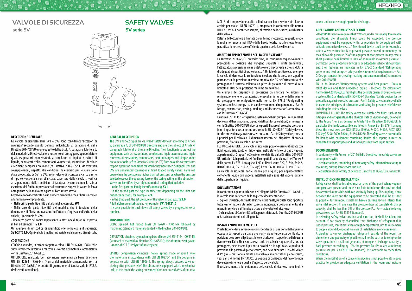
44 45
HFC/HFOHFC/HFO
VALVOLE DI SICUREZZA SAFETY VALVES
DESCRIZIONE GENERALELe valvole di sicurezza serie SV1 e SV2 sono considerate “accessori di sicurezza” secondo quanto definito nell’Articolo 2, paragrafo 4, della Direttiva 2014/68/EU e sono oggetto dell’Articolo 4, paragrafo 1, lettera d, della medesima Direttiva. La loro funzione è di proteggere apparecchiature quali, evaporatori, condensatori, accumulatori di liquido, ricevitori di liquido, separatori d’olio, compressori volumetrici, scambiatori di calore e recipienti semplici a pressione (rif. Direttiva 2009/105/CE) da eventuali sovrappressioni, rispetto alle condizioni di esercizio per le quali sono state progettate. Le SV1 e SV2, sono valvole di sicurezza a carico diretto di tipo convenzionale non bilanciate. L’apertura della valvola si verifica al superamento delle condizioni di taratura, ovvero quando la spinta esercitata dal fluido in pressione sull’otturatore, supera in valore la forza antagonista della molla che agisce sull’otturatore stesso.Le valvole sono identificate da un numero di modello che utilizza un codice alfanumerico comprendente:- Nella prima parte l’identità della famiglia, esempio: SV1- Nella seconda parte l’identità del modello, che è funzione della dimensione di filettatura realizzata sull’attacco d’ingresso e d’uscita della valvola; un esempio è: /24- Una terza parte del codice rappresenta la pressione di taratura, espressa in bar, ad esempio: T21.0Un esempio di un codice di identificazione completo è il seguente: SV1/24T21.0 . Ogni valvola è inoltre rintracciabile dal numero di matricola.
COSTRUZIONECORPO: a squadra, in ottone forgiato a caldo UNI EN 12420 - CW617N e successivamente lavorato a macchina. (Norma del materiale armonizzata con la Direttiva 2014/68/EU).OTTURATORE: realizzato per lavorazione meccanica da barra di ottone UNI EN 12164 - CW614N (Norma del materiale armonizzata con la Direttiva 2014/68/EU) è dotato di guarnizione di tenuta sede in P.T.F.E. (Politetrafluoroetilene).
GENERAL DESCRIPTIONThe SV1 and SV2 types are classified “safety devices” according to Article 2, paragraph 4, of 2014/68/EU Directive and are the subject of Article 4, paragraph 1, letter d, of the same Directive. Their function is to protect the equipment such as evaporators, condensers, liquid accumulators, liquid receivers, oil separators, compressors, heat exchangers and simple under pressure vessels (ref. to Directive 2009/105/CE) from possible overpressures respect operating conditions for which they have been designed. SV1 and SV2 are unbalanced conventional direct loaded safety valves. Valve will open when the pressure go higher than set pressure, or, when the pressure exerted exceeds the opposing force of the spring acting on the obturator.Valves are identified by an alphanumerical coding that includes:- in the first part the family identification e.g. SV1- in the second part the type identity, that depending on the inlet and outlet connections; for example: /24- in the third part, the set pressure of the valve, in bar, e.g.: T21.0 A full alphanumerical code is, for example: SV1/24T21.0It is also possible to track down all safety valves by a progressive serial number.
CONSTRUCTION BODY: squared, hot forged brass EN 12420 - CW617N followed by machining (standard material adapted with directive 2014/68/EU).
OBTURATOR: obtained by machining bars of brass UNI EN 12164 - CW614N, (standard of material as directive 2014/68/EU); the obturator seat gasket is made of P.T.F.E. (Polytetrafluorethylene).
SPRING: Compression cylindrical helical spring made of round wire; the material is in accordance with UNI EN 10270-1 and the design is in accordance with UNI EN 13906-1. The spring always ensures valve re-closing after pressure relief. The obturator is equipped with a mechanical lock, in this mode the spring movement does not exceed 85% of the total
serie SV SV series
MOLLA: di compressione a elica cilindrica con filo a sezione circolare in acciaio per molle UNI EN 10270-1, progettata in conformità alla norma UNI EN 13906-1 garantisce sempre, al termine dello scarico, la richiusura della valvola. L’alzata dell’otturatore è limitata da un fermo meccanico, in questo modo la molla non supera mai l’85% della freccia totale, ma allo stesso tempo garantisce la necessaria e sufficiente apertura della luce di scarico.
AMBITO DI APPLICAZIONE E SCELTA DELLE VALVOLE La Direttiva 2014/68/EU prevede: “Ove, in condizioni ragionevolmente prevedibili, è possibile che vengano superati i limiti ammissibili, l’attrezzatura a pressione viene dotata ovvero si provvede a che sia dotata di adeguati dispositivi di protezione,…”. Un tale dispositivo è ad esempio la valvola di sicurezza, la cui funzione è evitare che la pressione superi in permanenza la pressione massima ammissibile PS dell’attrezzatura che proteggono; è tuttavia tollerato un picco di pressione di breve durata limitato al 10% della pressione massima ammissibile.Un esempio dei dispositivi di protezione da adottare nei sistemi di refrigerazione e le loro caratteristiche peculiari in funzione dell’impianto da proteggere, sono riportate nella norma EN 378-2 “Refrigerating systems and heat pumps - safety and environmental requirements - Part2: Design, construction, testing, marking and documentation”, armonizzata con la Direttiva 2014/68/EU. La norma EN 13136 “Refrigerating systems and heat pumps - Pressure relief devices and their associated piping - Methods for calculation”, armonizzata con la Direttiva 2014/68/EU, riporta le possibili cause di eccessiva pressione in un impianto; questa norma così come la EN ISO 4126-1 “Safety devices for the protection against excessive pressure - Part1: Safety valves, mostra i principi per il calcolo e il dimensionamento dei dispositivi di scarico pressione, fra cui le valvole di sicurezza.FLUIDI COMPATIBILI: : Le valvole di sicurezza possono essere utilizzate con fluidi quali, aria, azoto e i frigorigeni, nello stato fisico di gas o vapore, appartenenti al Gruppo 1 o 2 così come è definito dalla Direttiva 2014/68/UE, articolo 13. In particolare i fluidi compatibili sono elencati nell’Annex E della norma EN 378-1, tra questi i più utilizzati sono: R22, R134a, R404A, R407C, R410A, R507, R32, R1234yf, R290, R600, R600a, R1150, R1270. La valvola di sicurezza non è idonea per i liquidi; per apparecchiature contenenti liquido con vapore, installarla nella zona del vapore lontano dalla superficie del liquido.
DOCUMENTAZIONEIn conformità a quanto richiesto nell’allegato I della Direttiva 2014/68/EU, le valvole sono corredate dalla seguente documentazione:- Foglio di istruzioni, destinato all’installatore finale, sul quale sono riportate tutte le informazioni utili ad un corretto montaggio e posizionamento, alla messa in servizio e all’ impiego sicuro delle valvole di sicurezza.- Dichiarazione di Conformità dell’apparecchiatura alla Direttiva 2014/68/EUredatta in conformità all’allegato IV.
INSTALLAZIONE DELLE VALVOLE L’installazione deve avvenire in corrispondenza di una zona dell’impianto occupata da vapori o da gas e ove non vi siano turbolenze del fluido; la posizione deve essere il più possibile verticale, con il cappellotto di chiusura rivolto verso l’alto. Un eventuale raccordo tra valvola e apparecchiatura da proteggere, deve essere il più corto possibile e in ogni caso, la perdita di pressione alla portata di pieno scarico, non deve superare il 3% del valore di Po (Po = pressione a monte della valvola alla portata di pieno scarico, vedi par. 7.4 norma EN 13136). La sezione di passaggio del raccordo non deve essere inferiore a quella d’ingresso della valvola.Il posizionamento e l’orientamento della valvola di sicurezza, sono inoltre
course and ensure enough space for discharge.
APPLICATIONS AND VALVES SELECTION2014/68/EU Directive requires that: “Where, under reasonably foreseeable conditions, the allowable limits could be exceeded, the pressure equipment must be equipped with, or provision to be equipped with suitable protective devices,…”. Mentioned device could be for example a safety valve; Its function is to prevent pressure exceed permanently the max allowable pressure PS of the equipment that protect. In any case, a short pressure peak limited to 10% of admissible maximum pressure is permitted. Some protection devices to be adopted in refrigerating systems and their features are indicates in EN 378-2 Standard “Refrigerating systems and heat pumps – safety and environmental requirements – Part 2: Design, construction, testing, marking and documentation”, harmonized with 2014/68/EU. EN 13136 Standard “Refrigerating systems and heat pumps - Pressure relief devices and their associated piping - Methods for calculation”, harmonized 2014/68/EU, highlights the possible causes of overpressure in a system; this Standard and EN ISO 4126-1 Standard “Safety devices for the protection against excessive pressure - Part1: Safety valves, make available to users the principles of calculation and sizing for pressure relief device, including the safety valves.COMPATIBLE FLUIDS: The safety valves are suitable for fluids such as air, nitrogen and refrigerants, in the physical state of vapour or gas, belonging to the Group 1 or 2 as defined in Article 13 of Directive 2014/68/UE. In particular the fluids compatible are listed in Annex E of EN 378-1, among these the most used are: R22, R134a, R404A, R407C, R410A, R507, R32, R1234yf, R290, R600, R600a, R1150, R1270. The safety valve is not suitable for liquid; with equipment containing liquids plus vapour, it must be connected to vapour space and as far as possible from liquid surface.
DOCUMENTATIONIn conformity with Annex I of 2014/68/EU Directive, the safety valves are accompanied with:- User instructions, containing all necessary safety information relating to mounting, putting into service and use.- Declaration of conformity of device to Directive 2014/68/EU as Annex IV.
INSTRUCTIONS FOR INSTALLATIONSafety valves shall be installed near an area of the plant where vapours and gases are present and there is no fluid turbulence; the position shall be as vertical as possible, with cap vertically facing up. The coupling, if any, between the valve and the equipment to be protected shall be as short as possible; furthermore, it shall not have a passage section inferior than valve inlet section. In any case the pressure drop, at complete discharge capacity, shall be less than 3% of the pressure Po, (Po = actual relieving pressure see par. 7.4 EN 13136 Standard).In selecting safety valve location and direction, it shall be taken into account, if not properly channelled ,that discharge of refrigerant fluid under pressure, sometimes even at high temperatures, not to cause harm to people around it, especially in case of installation in enclosed rooms. A pipeline to convey discharged refrigerant outside of the room; the dimensions and geometry of pipeline shall not be such as to compromise valve operation: it shall not generate, at complete discharge capacity, a back pressure exceeding by 10% the pressure Po, (Po = actual relieving pressure see par. 7.4 EN 13136 Standard). It is advisable to check these conditions.When the installation of a conveying pipeline is not possible, it’s a good practice to provide an adequate ventilation in the room and indicate,
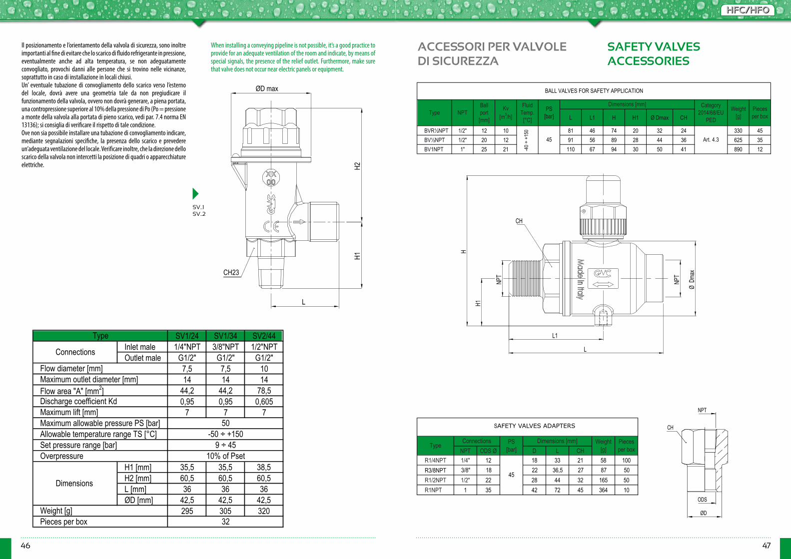
46 47
HFC/HFOHFC/HFO
Il posizionamento e l’orientamento della valvola di sicurezza, sono inoltre importanti al fine di evitare che lo scarico di fluido refrigerante in pressione, eventualmente anche ad alta temperatura, se non adeguatamente convogliato, provochi danni alle persone che si trovino nelle vicinanze, soprattutto in caso di installazione in locali chiusi.Un’ eventuale tubazione di convogliamento dello scarico verso l’esterno del locale, dovrà avere una geometria tale da non pregiudicare il funzionamento della valvola, ovvero non dovrà generare, a piena portata, una contropressione superiore al 10% della pressione di Po (Po = pressione a monte della valvola alla portata di pieno scarico, vedi par. 7.4 norma EN 13136); si consiglia di verificare il rispetto di tale condizione.Ove non sia possibile installare una tubazione di convogliamento indicare, mediante segnalazioni specifiche, la presenza dello scarico e prevedere un’adeguata ventilazione del locale. Verificare inoltre, che la direzione dello scarico della valvola non intercetti la posizione di quadri o apparecchiature elettriche.
When installing a conveying pipeline is not possible, it’s a good practice to provide for an adequate ventilation of the room and indicate, by means of special signals, the presence of the relief outlet. Furthermore, make sure that valve does not occur near electric panels or equipment.
L L1 H H1 Ø Dmax CH
BVR½NPT 1/2" 12 10 81 46 74 20 32 24 330 45BV½NPT 1/2" 20 12 91 56 89 28 44 36 625 35BV1NPT 1" 25 21 110 67 94 30 50 41 890 12
NPT ODS Ø D L CHR1/4NPT 1/4" 12 18 33 21 58 100R3/8NPT 3/8" 18 22 36,5 27 87 50R1/2NPT 1/2" 22 28 44 32 165 50R1NPT 1 35 42 72 45 364 10
45
Category 2014/68/EU
PED
45 Art. 4.3
Type NPTBall port [mm]
PS [bar]
Fluid Temp. [°C]
Kv[m3/h]
TypeConnections Pieces
per boxDimensions [mm] Weight
[g]
Weight [g]
Pieces per box
BALL VALVES FOR SAFETY APPLICATION
Dimensions [mm]
PS [bar]
SAFETY VALVES ADAPTER
-45 ÷
+15
0
ACCESSORI PER VALVOLEDI SICUREZZA
SAFETY VALVESACCESSORIES
ODS
ØD
NPT
CH
SV1/24 SV1/34 SV2/44Inlet male 1/4"NPT 3/8"NPT 1/2"NPTOutlet male G1/2" G1/2" G1/2"
7,5 7,5 1014 14 14
44,2 44,2 78,50,95 0,95 0,605
7 7 7
H1 [mm] 35,5 35,5 38,5H2 [mm] 60,5 60,5 60,5L [mm] 36 36 36ØD [mm] 42,5 42,5 42,5
295 305 320
Flow diameter [mm]Maximum outlet diameter [mm]
Type
Connections
Allowable temperature range TS [°C] -50 ÷ +150
Flow area "A" [mm2]Discharge coefficient KdMaximum lift [mm]Maximum allowable pressure PS [bar] 50
Weight [g]Pieces per box 32
Dimensions
Set pressure range [bar] 9 ÷ 45Overpressure 10% of Pset
H2
L
H1
ØD max
CH23
SV..1SV..2
L
NPT
L1
NPT
ØDm
ax
H1
H
CH
SAFETY VALVES ADAPTERS
-40 ÷
+15
0
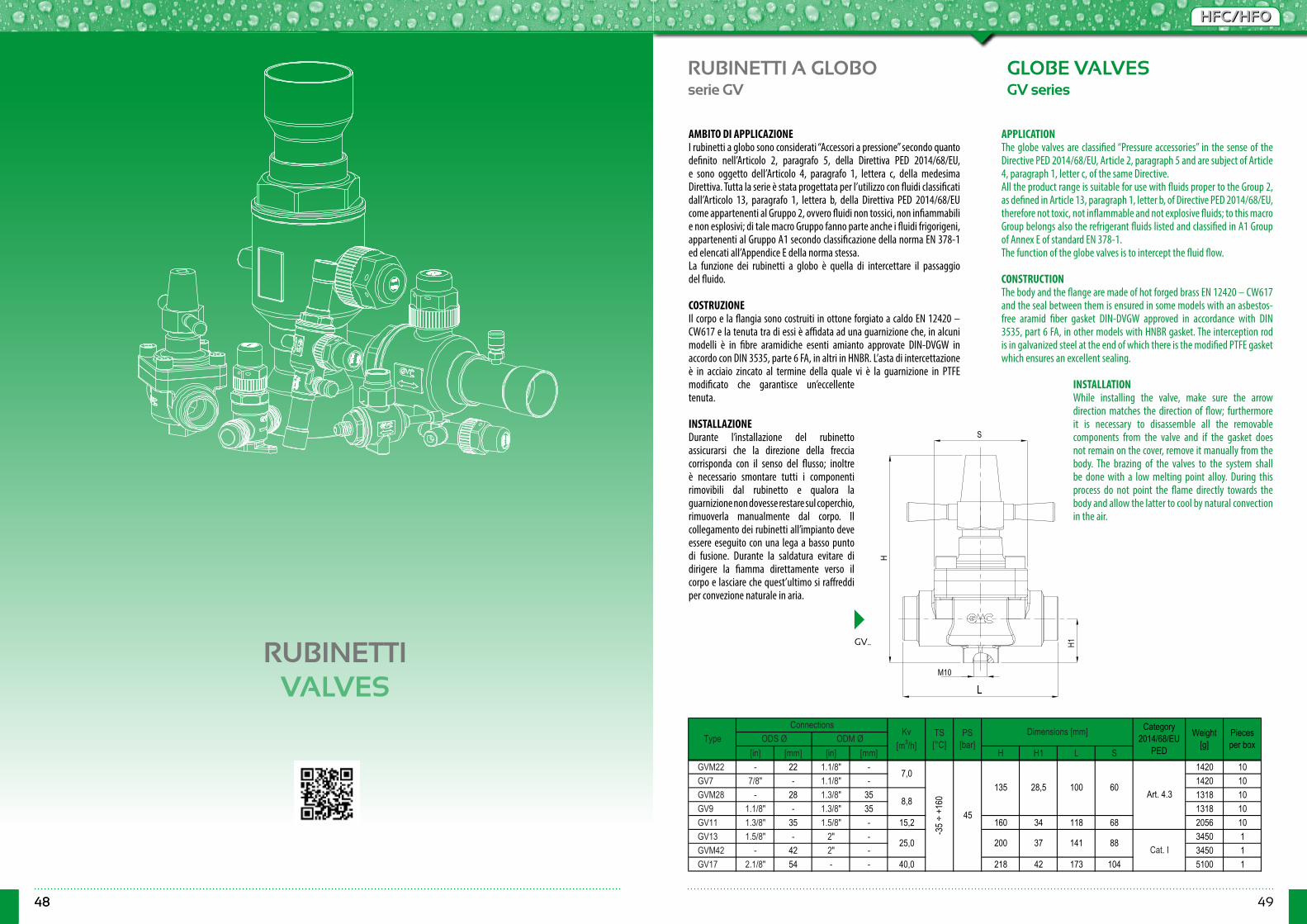
48 49
HFC/HFOHFC/HFO
48
RUBINETTI A GLOBO GLOBE VALVESserie GV GV series
AMBITO DI APPLICAZIONEI rubinetti a globo sono considerati “Accessori a pressione” secondo quanto definito nell’Articolo 2, paragrafo 5, della Direttiva PED 2014/68/EU,e sono oggetto dell’Articolo 4, paragrafo 1, lettera c, della medesima Direttiva. Tutta la serie è stata progettata per l’utilizzo con fluidi classificati dall’Articolo 13, paragrafo 1, lettera b, della Direttiva PED 2014/68/EU come appartenenti al Gruppo 2, ovvero fluidi non tossici, non infiammabili e non esplosivi; di tale macro Gruppo fanno parte anche i fluidi frigorigeni, appartenenti al Gruppo A1 secondo classificazione della norma EN 378-1 ed elencati all’Appendice E della norma stessa.La funzione dei rubinetti a globo è quella di intercettare il passaggio del fluido. COSTRUZIONEIl corpo e la flangia sono costruiti in ottone forgiato a caldo EN 12420 – CW617 e la tenuta tra di essi è affidata ad una guarnizione che, in alcuni modelli è in fibre aramidiche esenti amianto approvate DIN-DVGW in accordo con DIN 3535, parte 6 FA, in altri in HNBR. L’asta di intercettazione è in acciaio zincato al termine della quale vi è la guarnizione in PTFE modificato che garantisce un’eccellente tenuta.
INSTALLAZIONEDurante l’installazione del rubinetto assicurarsi che la direzione della freccia corrisponda con il senso del flusso; inoltre è necessario smontare tutti i componenti rimovibili dal rubinetto e qualora la guarnizione non dovesse restare sul coperchio, rimuoverla manualmente dal corpo. Il collegamento dei rubinetti all’impianto deve essere eseguito con una lega a basso punto di fusione. Durante la saldatura evitare di dirigere la fiamma direttamente verso il corpo e lasciare che quest’ultimo si raffreddi per convezione naturale in aria.
APPLICATIONThe globe valves are classified “Pressure accessories” in the sense of the Directive PED 2014/68/EU, Article 2, paragraph 5 and are subject of Article 4, paragraph 1, letter c, of the same Directive.All the product range is suitable for use with fluids proper to the Group 2, as defined in Article 13, paragraph 1, letter b, of Directive PED 2014/68/EU, therefore not toxic, not inflammable and not explosive fluids; to this macro Group belongs also the refrigerant fluids listed and classified in A1 Group of Annex E of standard EN 378-1.The function of the globe valves is to intercept the fluid flow. CONSTRUCTIONThe body and the flange are made of hot forged brass EN 12420 – CW617 and the seal between them is ensured in some models with an asbestos-free aramid fiber gasket DIN-DVGW approved in accordance with DIN 3535, part 6 FA, in other models with HNBR gasket. The interception rod is in galvanized steel at the end of which there is the modified PTFE gasket which ensures an excellent sealing.
INSTALLATIONWhile installing the valve, make sure the arrow direction matches the direction of flow; furthermore it is necessary to disassemble all the removable components from the valve and if the gasket does not remain on the cover, remove it manually from the body. The brazing of the valves to the system shall be done with a low melting point alloy. During this process do not point the flame directly towards the body and allow the latter to cool by natural convection in the air.
[in] [mm] [in] [mm] H H1 L SGVM22 - 22 1.1/8" - 1420 10GV7 7/8" - 1.1/8" - 1420 10GVM28 - 28 1.3/8" 35 1318 10GV9 1.1/8" - 1.3/8" 35 1318 10GV11 1.3/8" 35 1.5/8" - 15,2 160 34 118 68 2056 10GV13 1.5/8" - 2" - 3450 1GVM42 - 42 2" - 3450 1GV17 2.1/8" 54 - - 40,0 218 42 173 104 5100 1
Weight [g]
Pieces per box
Dimensions [mm] Category 2014/68/EU
PEDODS Ø ODM ØType
ConnectionsKv
[m3/h]PS
[bar]TS [°C]
100 60Art. 4.3
8,8
25,0 200 37 141 88Cat. I
7,0
-35 ÷
+16
0
45
135 28,5
RUBINETTIVALVES
S
H1
L
H
M10
GV..

50 51
HFC/HFOHFC/HFO
RUBINETTI A SFERA BALL VALVESserie BV BV series
BV..A BV .. BV..A
BV2-2M
Without access fitting
With access fitting [in] [mm] L L1 L2 H H1 Ø Dmax M K
BV2-2M - 0,6 62 96 39 310 45BV2 1/4" - 1,1 290 35BV3 3/8" - 292 35BVM10 - 10 292 35BVM12 - 12 295 35BV4 1/2" - 295 35BV5 5/8" 16 14,2 135 69 298 35BVM18 BVM18A - 18 46 590 12BV6 BV6A 3/4" - 45 595 12BV7 BV7A 7/8" 22 169 86 48 640 12BV9R - 1.1/8" - 198 102 - 675 15BVM28 BVM28A - 28 55 870 15BV9 BV9A 1.1/8" - 55 935 15BV11R - 1.3/8" 35 250 130 - 970 12BV11 BV11A 1.3/8" 35 67 1835 5BV13R - 1.5/8" - - 1830 5BVM42R - - 42 - 1830 5BV13 BV13A 1.5/8" - 75 2680 5BVM42 BVM42A - 42 75 2685 5BV17R - 2.1/8" 54 292 152 - 2810 4BV17 BV17A 2.1/8" 54 86 4560 4BV21 BV21A 2.5/8" - 77 4635 4BVM64R BVM64RA - 64 190,0 75 4600 4BVM64 BVM64A - 64 93 8200 1BV21D BV21DA 2.5/8" - 98 8355 1BV24R BV24RA 3" 76 95 8500 1BV25R BV25RA 3.1/8" 80 95 8550 1
120
122
177330
350
245
294
260
153
18
62 76 22 32
89 28
-
M5
80
66
75
94
76
160
137
55
120
38
M6
M10
109
18762169
130
Type
27,5
3,2
6,0
50185,0
40,5
20
32 67,5
25
See t
able
below
Fluid temp. [°C]
PS [bar]
Ball port [mm]
ODS Ø
18,0
See picture below
Kv [m3/h]
-45 ÷
+15
0
45
12
40 115,0
295,065
Pieces per box
Cat. I92
Weight [g]
Category 2014/68/EU
PED
Art. 4.3
Dimensions [mm]
50
44
30
131 45
150
119
207
30
[in] [mm] L L1 L3 H H1 Ø Dmax M K
BV2A 1/4" - 1,1 348 35BV3A 3/8" - 3,2 346 35BVM10A - 10 3,2 346 35BVM12A - 12 6,0 344 35BV4A 1/2" - 6,0 344 35BV5A 5/8" 16 14,2 152 69 336 35
TypeODS Ø Ball
port [mm]
Kv [m3/h]
Fluid temp. [°C]
PS [bar]
Category 2014/68/EU
PED
Weight [g]
Pieces per box
-45 ÷
+15
0
45
Dimensions [mm]
M512 76 Art. 4.31832222962136
AMBITO DI APPLICAZIONEI rubinetti a sfera sono considerati “Accessori a pressione” secondo quanto definito nell’Articolo 2, paragrafo 5, della Direttiva PED 2014/68/EU e sono oggetto dell’Articolo 4, paragrafo 1, lettera c, della medesima Direttiva. Tutta la serie è stata progettata per l’utilizzo con fluidi classificati dall’Articolo 13, paragrafo 1, lettera b, della Direttiva PED 2014/68/EUcome appartenenti al Gruppo 2, ovvero fluidi non tossici, non infiammabili e non esplosivi; di tale macro Gruppo fanno parte anche i fluidi frigorigeni, appartenenti al Gruppo A1 secondo classificazione della norma EN 378-1 ed elencati all’Appendice E della norma stessa.
COSTRUZIONEIl corpo e la sfera cromata dei rubinetti sono realizzati in ottone forgiato a caldo UNI EN 12420 – CW617N e le relative connessione a saldare sono in tubo di rame EN 12735-1 – Cu-DHP. La saldatura TIG tra corpo e manicotto e gli anelli di tenuta in cloroprene (CR), poste sull’asta di manovra, assicurano la perfetta ermeticità del rubinetto, mentre le guarnizioni di tenuta sulla sfera, in speciale PTFE modificato, garantiscono basse coppie di manovra. Il progetto del rubinetto è tale da consentire la bidirezionalità del flusso del fluido refrigerante, garantire il bilanciamento interno delle pressioni a rubinetto chiuso ed evitare il pericolo di espulsione dell’asta di manovra. Quest’ultima è in acciaio trattato e la relativa spina di fermo è in acciaio inox.
INSTALLAZIONEIl collegamento dei rubinetti all’impianto deve essere eseguito con una lega a basso punto di fusione.Durante la saldatura evitare di dirigere la fiamma direttamente verso il corpo tenendo quest’ultimo raffreddato per evitare di compromettere la tenuta delle guarnizioni.
APPLICATIONThe ball valves are classified “Pressure accessories” in the sense of the Directive PED 2014/68/EU, Article 2, paragraph 5 and are subject of Article 4, paragraph 1, letter c, of the same Directive. All the product range is suitable for use with fluids proper to the Group 2, as defined in Article 13, paragraph 1, letter b, of Directive PED 2014/68/EU, therefore not toxic, not inflammable and not explosive fluids; to this macro Group belongs also the refrigerant fluids listed and classified in A1 Group of Annex E of standard EN 378-1. CONSTRUCTIONThe body and the chromium plated ball are manufactured in hot-forged brass EN 12420 – CW617N and the solder connections are in copper tube EN 12735-1 – Cu-DHP. The TIG welding of the body and the Chloroprene rubber (CR) O-ring assembled on the spindle, assure the perfect seal of the valves, while the special modified PTFE gaskets around the ball, ensures low working torque. The design of ball valves permits the bi-directional flow of the refrigerant, the equilibrium of internal pressures when the valve is closed and prevents any risk of ejection of galvanized steel spindle. The groove is made of stainless steel.
INSTALLATIONThe brazing of the valves to the system shall be done with a low melting point alloy. During this process do not point the flame directly towards the body keeping it cooled in order to avoid compromising the seal of the gaskets.
L1L
ØDm
ax
H
MK
H1
L1
L
L2
H1H
Ø Dm
ax
ØDm
ax
L1
L
H
H1
L3
L
L1
ØDm
ax
Ø1/
4" O
DS
H1
H
CH 24
7/16
" UNF
20fil/
1"
-40 ÷
+15
0
-40 ÷
+15
0
38
45
45

52 53
HFC/HFOHFC/HFO
RUBINETTI A CAPPELLOTTO CAPPED VALVESserie CSV CSV series
CSV
CSV..S
[in] [mm] H1 H2 L1 Ød I CHCSV2 1/4" - - 0,4 68 275 45CSV3 3/8" - - 1,0 74 285 45CSV4 1/2" - - 1,5 295 45CSV5 5/8" - - 1,7 300 45CSV2S - 1/4" - 0,4 57 265 45CSV3S - 3/8" - 260 45CSVM10S - - 10 260 45CSVM12S - - 12 270 45CSV4S - 1/2" - 265 45CSV5S - 5/8" - 1,7 71 265 45CSV6S - 3/4" - 3,4 685 15CSV7S - 7/8" - 3,4 690 15
Art. 4.3
Category 2014/68/EU
PED
34
TS [°C]
104 6 50
Pieces per box
-60 ÷
+11
0
45
129 109
Weight [g]Type SAE
Flare
1,5
Kv [m3/h]
70
68
PS [bar]
Dimensions [mm]ODS Ø
Connections
1,027
61
78
86 384,5
AMBITO DI APPLICAZIONEI rubinetti a cappellotto sono considerati “Accessori a pressione” secondo quanto definito nell’Articolo 2, paragrafo 5, della Direttiva PED 2014/68/EU e sono oggetto dell’Articolo 4, paragrafo 1, lettera c, della medesima Direttiva. Tutta la serie è stata progettata per l’utilizzo con fluidi classificati dall’Articolo 13, paragrafo 1, lettera b, della Direttiva PED 2014/68/EU come appartenenti al Gruppo 2, ovvero fluidi non tossici, non infiammabili e non esplosivi; di tale macro Gruppo fanno parte anche i fluidi frigorigeni, appartenenti al Gruppo A1 secondo classificazione della norma EN 378-1 ed elencati all’Appendice E della norma stessa.La funzione dei rubinetti a cappellotto è quella di intercettare il passaggio del fluido consentendo di effettuare manovre di manutenzione.
COSTRUZIONEIl corpo valvola è realizzato in ottone forgiato a caldo UNI EN 12420 – CW617N mentre l’asta di manovra è in acciaio zincato. Un pacchetto composto da guarnizioni in gomma cloroprene e guarnizioni in fibre aramidiche, approvate da DIN-DVGW secondo la norma DIN 3535, parte 6 FA, garantisce un’ottima tenuta verso l’esterno tra l’asta di manovra e il premistoppa.
INSTALLAZIONELeggere attentamente le istruzioni di installazione contenute nell’imballo del prodotto. Per i modelli CSV..S è necessario smontare il gruppo ghiera porta asta, agendo sull’esagono indicato, prima di saldobrasare il corpo all’impianto. Il collegamento dei rubinetti all’impianto deve essere eseguito con una lega a basso punto di fusione. Durante la saldatura evitare di dirigere la fiamma direttamente verso il corpo per evitare residui di combustione sulle sedi di tenuta.
APPLICATIONThe capped valves are classified “Pressure accessories” in the sense of the Directive PED 2014/68/EU, Article 2, paragraph 5 and are subject of Article 4, paragraph 1, letter c, of the same Directive.All the product range is suitable for use with fluids proper to the Group 2, as defined in Article 13, paragraph 1, letter b, of Directive PED 2014/68/EU, therefore not toxic, not inflammable and not explosive fluids; to this macro Group belongs also the refrigerant fluids listed and classified in A1 Group of Annex E of standard EN 378-1. The function of the capped valves is to intercept the fluid flow to allow maintenance operations. CONSTRUCTIONThe valve body is made of hot forged brass EN 12420 - CW617N and the spindle is made of galvanized steel. A package consisting of chloroprene rubber seals and aramid fibers gaskets, approved by DIN-DVGW in accordance with DIN 3535, part 6 FA, guarantees an excellent seal to the outside between the spindle and the gland.
INSTALLATIONRead carefully the installation instructions included in the box. For the CSV..S types is necessary disassemble the valve, acting on the indicated hexagon, before brazing the body to the system. The brazing shall be done with a low melting point alloy. During this process do not point the flame directly towards the body in order to prevent to leave combustion residues on the sealing seats.
L1
H1
H2
CH
H2
H1
L1
CH
I
Ød
-40 ÷
+13
0
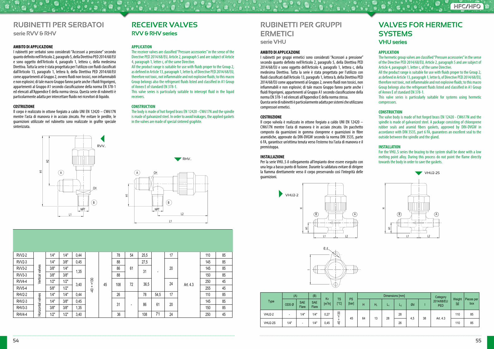
54 55
HFC/HFOHFC/HFO
Type(A) (B)
Kv [m3/h]
TS [°C]
PS [bar]
Dimensions [mm] Category 2014/68/EU
PEDWeight
[g]Pieces per boxSAE
Flare NPT H1 H2 L1 L2 CH
RVV2-2 1/4" 1/4" 0,44
45
78 54 25,5
-
17
Art. 4.3
110 85RVV2-3 1/4" 3/8" 0,45 88
6127,5
20145 85
RVV3-2 3/8" 1/4"1,35
8631
145 85RVV3-3 3/8" 3/8" 88 150 85RVV4-4 1/2" 1/2"
3,40 108250 45
RVV5-4 5/8" 1/2" 255 45RHV2-2 1/4" 1/4" 0,44 26
-
78 54,5 17 110 85RHV2-3 1/4" 3/8" 0,45
31 86 61 20145 85
RHV3-3 3/8" 3/8" 1,35 150 85RHV4-4 1/2" 1/2" 3,40 108 250 45
24
24
36,572
36
L1
H2
H1
H1
L1
L2NPT
CH
BB
AA CH
NPT
RUBINETTI PER SERBATOI RECEIVER VALVESserie RVV & RHV RVV & RHV series
AMBITO DI APPLICAZIONEI rubinetti per serbatoi sono considerati “Accessori a pressione” secondo quanto definito nell’Articolo 2, paragrafo 5, della Direttiva PED 2014/68/EU e sono oggetto dell’Articolo 4, paragrafo 1, lettera c, della medesima Direttiva. Tutta la serie è stata progettata per l’utilizzo con fluidi classificati dall’Articolo 13, paragrafo 1, lettera b, della Direttiva PED 2014/68/EU come appartenenti al Gruppo 2, ovvero fluidi non tossici, non infiammabili e non esplosivi; di tale macro Gruppo fanno parte anche i fluidi frigorigeni, appartenenti al Gruppo A1 secondo classificazione della norma EN 378-1 ed elencati all’Appendice E della norma stessa. Questa serie di rubinetti è particolarmente adatta per intercettare fluido nei ricevitori di liquido.
COSTRUZIONEIl corpo è realizzato in ottone forgiato a caldo UNI EN 12420 – CW617N mentre l’asta di manovra è in acciaio zincato. Per evitare le perdite, le guarnizioni utilizzate nel rubinetto sono realizzate in grafite speciale sinterizzata.
APPLICATIONThe receiver valves are classified “Pressure accessories” in the sense of the Directive PED 2014/68/EU, Article 2, paragraph 5 and are subject of Article 4, paragraph 1, letter c, of the same Directive.All the product range is suitable for use with fluids proper to the Group 2, as defined in Article 13, paragraph 1, letter b, of Directive PED 2014/68/EU, therefore not toxic, not inflammable and not explosive fluids; to this macro Group belongs also the refrigerant fluids listed and classified in A1 Group of Annex E of standard EN 378-1.This valve series is particularly suitable to intercept fluid in the liquid receivers.
CONSTRUCTIONThe body is made of hot forged brass EN 12420 - CW617N and the spindle is made of galvanized steel. In order to avoid leakages, the applied gaskets in the valves are made of special sintered graphite.
RVV..
RHV..
RUBINETTI PER GRUPPI ERMETICI
VALVES FOR HERMETICSYSTEMS
serie VHU VHU series
AMBITO DI APPLICAZIONEI rubinetti per gruppi ermetici sono considerati “Accessori a pressione” secondo quanto definito nell’Articolo 2, paragrafo 5, della Direttiva PED 2014/68/EU e sono oggetto dell’Articolo 4, paragrafo 1, lettera c, della medesima Direttiva. Tutta la serie è stata progettata per l’utilizzo con fluidi classificati dall’Articolo 13, paragrafo 1, lettera b, della Direttiva PED 2014/68/EU come appartenenti al Gruppo 2, ovvero fluidi non tossici, non infiammabili e non esplosivi; di tale macro Gruppo fanno parte anche i fluidi frigorigeni, appartenenti al Gruppo A1 secondo classificazione della norma EN 378-1 ed elencati all’Appendice E della norma stessa.Questa serie di rubinetti è particolarmente adatta per sistemi che utilizzano compressori ermetici.
COSTRUZIONEIl corpo valvola è realizzato in ottone forgiato a caldo UNI EN 12420 – CW617N mentre l’asta di manovra è in acciaio zincato. Un pacchetto composto da guarnizioni in gomma cloroprene e guarnizioni in fibre aramidiche, approvate da DIN-DVGW secondo la norma DIN 3535, parte 6 FA, garantisce un’ottima tenuta verso l’esterno tra l’asta di manovra e il premistoppa.
INSTALLAZIONEPer la serie VHU..S il collegamento all’impianto deve essere eseguito con una lega a basso punto di fusione. Durante la saldatura evitare di dirigere la fiamma direttamente verso il corpo preservando così l’integrità delle guarnizioni.
APPLICATIONThe hermetic group valves are classified “Pressure accessories” in the sense of the Directive PED 2014/68/EU, Article 2, paragraph 5 and are subject of Article 4, paragraph 1, letter c, of the same Directive.All the product range is suitable for use with fluids proper to the Group 2, as defined in Article 13, paragraph 1, letter b, of Directive PED 2014/68/EU, therefore not toxic, not inflammable and not explosive fluids; to this macro Group belongs also the refrigerant fluids listed and classified in A1 Group of Annex E of standard EN 378-1.This valve series is particularly suitable for systems using hermetic compressors.
CONSTRUCTIONThe valve body is made of hot forged brass EN 12420 - CW617N and the spindle is made of galvanized steel. A package consisting of chloroprene rubber seals and aramid fibers gaskets, approved by DIN-DVGW in accordance with DIN 3535, part 6 FA, guarantees an excellent seal to the outside between the spindle and the gland.
INSTALLATIONFor the VHU..S series the brazing to the system shall be done with a low melting point alloy. During this process do not point the flame directly towards the body in order to save the gaskets.
Ø d
I
L1
H
H1
AB B A
L2 L1
H
H1
L2
VHU2-2
VHU2-2S
-40 ÷
+13
0
Vertic
al va
lves
Horiz
ontal
valve
s (B)
ODS Ø SAE Flare
SAE Flare H H1 L1 L2 Ød I
VHU2-2 - 1/4" 1/4" 0,27 28 110 85
VHU2-2S 1/4" - 1/4" 0,45 26 110 85
Weight [g]
Pieces per box
Dimensions [mm]
384,564
Kv [m3/h]
28
TypeCategory
2014/68/EU PED
PS [bar]
(A)TS [°C]
45 Art. 4.3
-40 ÷
+13
0
1371
Ø d
I
L1
H
H1
AB B A
L2 L1
H
H1
L2
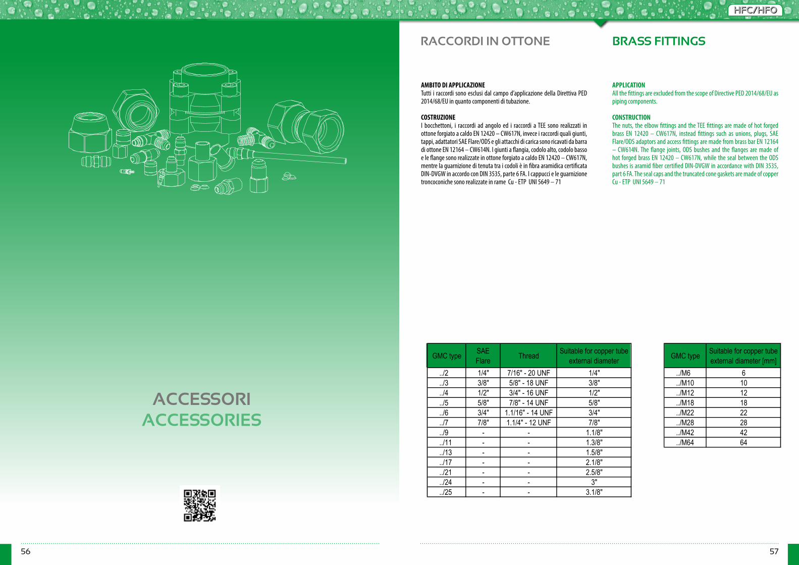
56 57
HFC/HFOHFC/HFO
RACCORDI IN OTTONE
ACCESSORIACCESSORIES
BRASS FITTINGS
AMBITO DI APPLICAZIONETutti i raccordi sono esclusi dal campo d’applicazione della Direttiva PED 2014/68/EU in quanto componenti di tubazione. COSTRUZIONE I bocchettoni, i raccordi ad angolo ed i raccordi a TEE sono realizzati in ottone forgiato a caldo EN 12420 – CW617N, invece i raccordi quali giunti, tappi, adattatori SAE Flare/ODS e gli attacchi di carica sono ricavati da barra di ottone EN 12164 – CW614N. I giunti a flangia, codolo alto, codolo basso e le flange sono realizzate in ottone forgiato a caldo EN 12420 – CW617N, mentre la guarnizione di tenuta tra i codoli è in fibra aramidica certificata DIN-DVGW in accordo con DIN 3535, parte 6 FA. I cappucci e le guarnizione troncoconiche sono realizzate in rame Cu - ETP UNI 5649 – 71
APPLICATIONAll the fittings are excluded from the scope of Directive PED 2014/68/EU as piping components.
CONSTRUCTION The nuts, the elbow fittings and the TEE fittings are made of hot forged brass EN 12420 – CW617N, instead fittings such as unions, plugs, SAE Flare/ODS adaptors and access fittings are made from brass bar EN 12164 – CW614N. The flange joints, ODS bushes and the flanges are made of hot forged brass EN 12420 – CW617N, while the seal between the ODS bushes is aramid fiber certified DIN-DVGW in accordance with DIN 3535, part 6 FA. The seal caps and the truncated cone gaskets are made of copper Cu - ETP UNI 5649 – 71
GMC type SAE Flare Thread Suitable for copper tube
external diameter GMC type Suitable for copper tube external diameter [mm]
../2 1/4" 7/16" - 20 UNF 1/4" ../M6 6
../3 3/8" 5/8" - 18 UNF 3/8" ../M10 10
../4 1/2" 3/4" - 16 UNF 1/2" ../M12 12
../5 5/8" 7/8" - 14 UNF 5/8" ../M18 18
../6 3/4" 1.1/16" - 14 UNF 3/4" ../M22 22
../7 7/8" 1.1/4" - 12 UNF 7/8" ../M28 28
../9 - - 1.1/8" ../M42 42
../11 - - 1.3/8" ../M64 64
../13 - - 1.5/8"
../17 - - 2.1/8"
../21 - - 2.5/8"
../24 - - 3"
../25 - - 3.1/8"
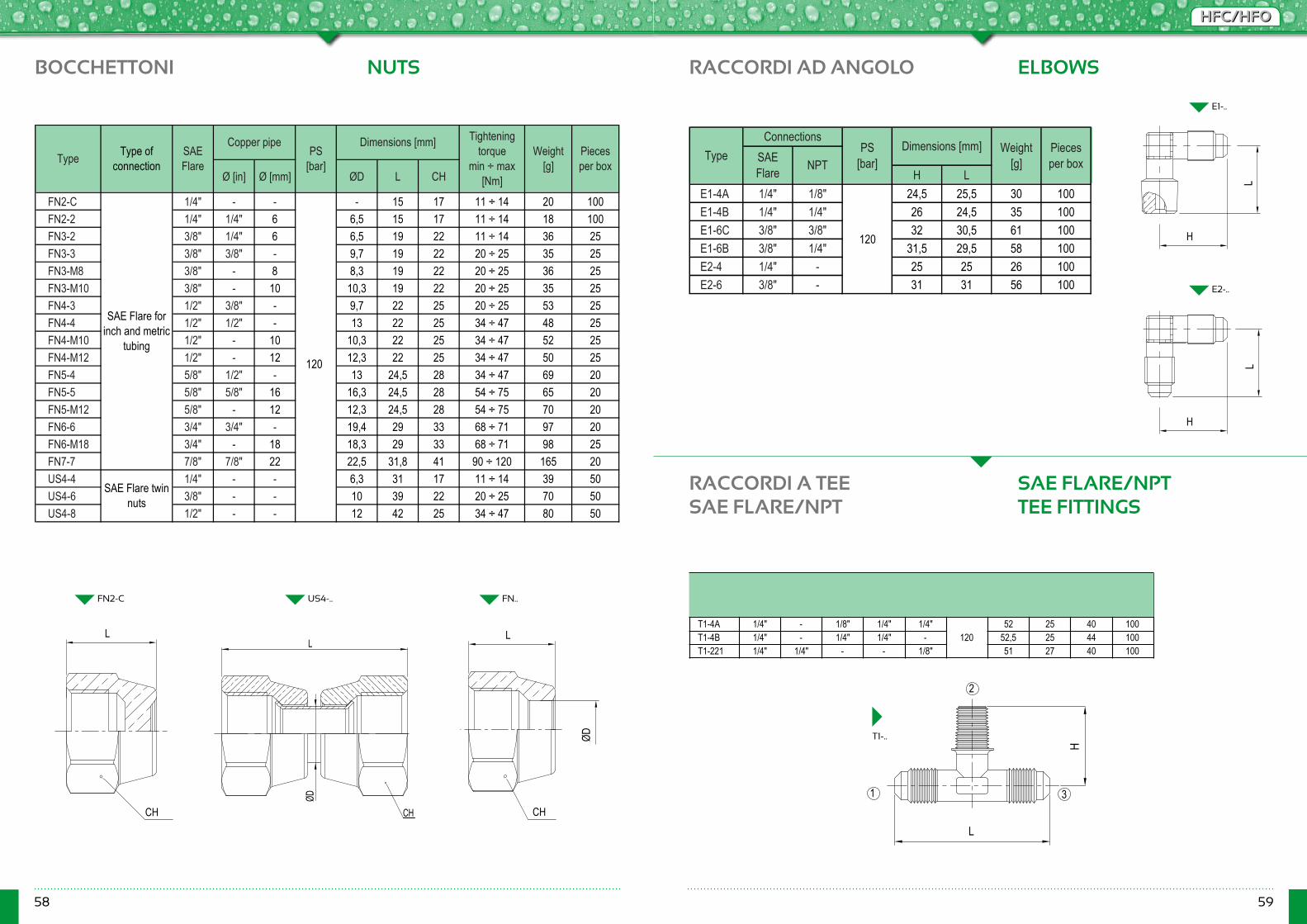
58 59
HFC/HFOHFC/HFO
Type(1) (2) (3)
PS [bar]
Dimensions [mm]Weight
[g]Pieces per boxSAE
FlareSAE Flare NPT SAE
Flare NPT L H
T1-4A 1/4" - 1/8" 1/4" 1/4"120
52 25 40 100T1-4B 1/4" - 1/4" 1/4" - 52,5 25 44 100T1-221 1/4" 1/4" - - 1/8" 51 27 40 100
1
H
L
1 3
2
BOCCHETTONI RACCORDI AD ANGOLO
RACCORDI A TEE SAE FLARE/NPT
NUTS ELBOWS
SAE FLARE/NPT TEE FITTINGS
Ø [in] Ø [mm] ØD L CH
FN2-C 1/4" - - - 15 17 11 ÷ 14 20 100FN2-2 1/4" 1/4" 6 6,5 15 17 11 ÷ 14 18 100FN3-2 3/8" 1/4" 6 6,5 19 22 11 ÷ 14 36 25FN3-3 3/8" 3/8" - 9,7 19 22 20 ÷ 25 35 25FN3-M8 3/8" - 8 8,3 19 22 20 ÷ 25 36 25FN3-M10 3/8" - 10 10,3 19 22 20 ÷ 25 35 25FN4-3 1/2" 3/8" - 9,7 22 25 20 ÷ 25 53 25FN4-4 1/2" 1/2" - 13 22 25 34 ÷ 47 48 25FN4-M10 1/2" - 10 10,3 22 25 34 ÷ 47 52 25FN4-M12 1/2" - 12 12,3 22 25 34 ÷ 47 50 25FN5-4 5/8" 1/2" - 13 24,5 28 34 ÷ 47 69 20FN5-5 5/8" 5/8" 16 16,3 24,5 28 54 ÷ 75 65 20FN5-M12 5/8" - 12 12,3 24,5 28 54 ÷ 75 70 20FN6-6 3/4" 3/4" - 19,4 29 33 68 ÷ 71 97 20FN6-M18 3/4" - 18 18,3 29 33 68 ÷ 71 98 25FN7-7 7/8" 7/8" 22 22,5 31,8 41 90 ÷ 120 165 20US4-4 1/4" - - 6,3 31 17 11 ÷ 14 39 50US4-6 3/8" - - 10 39 22 20 ÷ 25 70 50US4-8 1/2" - - 12 42 25 34 ÷ 47 80 50
Type SAE Flare
Copper pipePS
[bar]
Dimensions [mm]Type of
connectionWeight
[g]Pieces per box
Tightening torque
min ÷ max [Nm]
SAE Flare for inch and metric
tubing
SAE Flare twin nuts
45
H LE1-4A 1/4" 1/8" 24,5 25,5 30 100E1-4B 1/4" 1/4" 26 24,5 35 100E1-6C 3/8" 3/8" 32 30,5 61 100E1-6B 3/8" 1/4" 31,5 29,5 58 100E2-4 1/4" - 25 25 26 100E2-6 3/8" - 31 31 56 100
Pieces per box
45
Connections
NPTType SAE
Flare
PS [bar]
Dimensions [mm] Weight[g]
L
CH
L
ØD
CH
L
CH
ØD
FN2-C US4-.. FN..
T1-..
E1-..
E2-..
H
LL
H
120
120
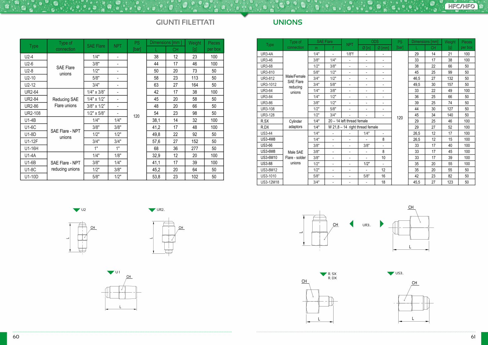
60 61
HFC/HFOHFC/HFO
GIUNTI FILETTATI UNIONS
L CHU2-4 1/4" - 38 12 23 100U2-6 3/8" - 44 17 46 100U2-8 1/2" - 50 20 73 50U2-10 5/8" - 58 23 113 50U2-12 3/4" - 63 27 164 50UR2-64 1/4" x 3/8” - 42 17 38 100UR2-84 1/4" x 1/2” - 45 20 58 50UR2-86 3/8" x 1/2” - 48 20 66 50UR2-108 1/2" x 5/8” - 54 23 98 50U1-4B 1/4" 1/4" 38,1 14 32 100U1-6C 3/8" 3/8" 41,2 17 48 100U1-8D 1/2" 1/2" 49,8 22 92 50U1-12F 3/4" 3/4" 57,6 27 152 50U1-16H 1" 1" 68 36 277 50U1-4A 1/4" 1/8" 32,9 12 20 100U1-6B 3/8" 1/4" 41,1 17 39 100U1-8C 1/2" 3/8" 45,2 20 64 50U1-10D 5/8" 1/2" 53,8 23 102 50
Type Type of connection SAE Flare NPT Weight
[g]Dimensions [mm ]PS
[bar]
Reducing SAE Flare unions
SAE Flare - NPT unions
SAE Flare - NPT reducing unions
45
Pieces per box
SAE Flare unions
m f Ø [in] Ø [mm] L CHUR3-4A 1/4" - 1/8"f - - 29 14 21 100UR3-46 3/8" 1/4" - - - 33 17 38 100UR3-68 1/2" 3/8" - - - 38 22 66 50UR3-810 5/8" 1/2" - - - 45 25 99 50UR3-812 3/4" 1/2" - - - 46,5 27 132 50UR3-1012 3/4" 5/8" - - - 49,5 30 157 50UR3-64 1/4" 3/8" - - - 33 22 49 100UR3-84 1/4" 1/2" - - - 36 25 66 50UR3-86 3/8" 1/2" - - - 39 25 74 50UR3-108 1/2" 5/8" - - - 44 30 127 50UR3-128 1/2" 3/4" - - - 45 34 140 50R.SX 1/4" 29 25 46 100R.DX 1/4" 29 27 52 100US3-44 1/4" - - 1/4" - 26,5 12 17 100US3-4M8 1/4" - - - 8 26,5 12 15 100US3-66 3/8" - - 3/8" - 33 17 40 100US3-6M8 3/8" - - - 8 33 17 45 100US3-6M10 3/8" - - - 10 33 17 39 100US3-88 1/2" - - 1/2" - 35 20 55 100US3-8M12 1/2" - - - 12 35 20 55 50US3-1010 5/8" - - 5/8" 16 42 23 82 50US3-12M18 3/4" - - - 18 45,5 27 123 50
Type
45
Male SAE Flare - solder
unions
PS [bar]
Pieces per box
Type of connection
Dimensions [mm] Weight[g]
Male/Female SAE Flare reducing unions
ODS
Cylinder adaptors
SAE FlareNPT
W 21,8 – 14 right thread female20 – 14 left thread female
L L
L
CH CH
CH
U2
U 1
UR2..
US3..
L
L
CH
CH
L
CH
L
CH
R. SXR. DX
UR3..
120 120
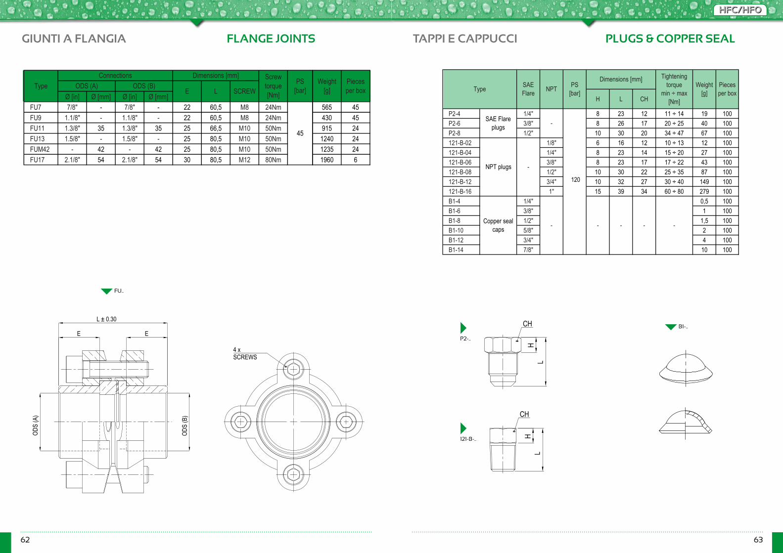
62 63
HFC/HFOHFC/HFO
TAPPI E CAPPUCCI PLUGS & COPPER SEAL
H L CH
P2-4 1/4" 8 23 12 11 ÷ 14 19 100P2-6 3/8" 8 26 17 20 ÷ 25 40 100P2-8 1/2" 10 30 20 34 ÷ 47 67 100121-B-02 1/8" 6 16 12 10 ÷ 13 12 100121-B-04 1/4" 8 23 14 15 ÷ 20 27 100121-B-06 3/8" 8 23 17 17 ÷ 22 43 100121-B-08 1/2" 10 30 22 25 ÷ 35 87 100121-B-12 3/4" 10 32 27 30 ÷ 40 149 100121-B-16 1" 15 39 34 60 ÷ 80 279 100B1-4 1/4" 0,5 100B1-6 3/8" 1 100B1-8 1/2" 1,5 100B1-10 5/8" 2 100B1-12 3/4" 4 100B1-14 7/8" 10 100
- --Copper seal caps -
45
NPT plugs -
-
Pieces per boxType
-
Tightening torque
min ÷ max [Nm]
Weight[g]
SAE Flare NPT
Dimensions [mm]PS
[bar]
SAE Flare plugs
B1-..
GIUNTI A FLANGIA FLANGE JOINTS
Ø [in] Ø [mm] Ø [in] Ø [mm]FU7 7/8" - 7/8" - 22 60,5 M8 24NmFU9 1.1/8" - 1.1/8" - 22 60,5 M8 24NmFU11 1.3/8" 35 1.3/8" 35 25 66,5 M10 50NmFU13 1.5/8" - 1.5/8" - 25 80,5 M10 50NmFUM42 - 42 - 42 25 80,5 M10 50NmFU17 2.1/8" 54 2.1/8" 54 30 80,5 M12 80Nm
Type
45
ConnectionsODS (B)
Dimensions [mm]
E L SCREWODS (A)
Screw torque [Nm]
PS [bar]
565 45430 45915 24
1240 241235 241960 6
Pieces per box
Weight[g]
L ± 0.30
E E
OD
S (A
)
OD
S (B
)
4 x SCREWS
FU..
L
CH
CH
HL
H
P2-..
121-B-..
120

64 65
HFC/HFOHFC/HFO
ADATTATORI SAE FLARE/ODS
SAE FLARE/ODS ADAPTERS
Ø [in] Ø [mm]G2 1/4" 1/4" - 16 12,5 17 25 100R2 1/4" 1/4" - 21 3,5 - 5 100RM6 1/4" - 6 21 3,5 - 5 100G3 3/8" 3/8" - 18,5 14,7 22 40 100R3 3/8" 3/8" - 23,5 4 - 10 100RM10 3/8" - 10 23,5 4 - 10 100G4 1/2" 1/2" - 21 17 27 70 50R4 1/2" 1/2" - 23,5 4 - 15 50RM12 1/2" - 12 23,5 4 - 15 50G5 5/8" 5/8" - 22,5 18 30 85 50R5 5/8" 5/8" - 27,5 5 - 20 50G6 3/4" 3/4" - 25 20 36 130 50R6 3/4" 3/4" - 30 5 - 40 50RM18 3/4" - 18 30 5 - 35 50G7 7/8" 7/8" - 30 25 41 188 25R7 7/8" 7/8" - 37 9 - 50 25
120
Pieces per boxSAE
FlareODS
H H1 CHType
ConnectionsPS
[bar]Weight
[g]
G..
R..
H
H1
SAE Flare
CH
H1
H
Ø ODS
GUARNIZIONI COPPER GASKETS
000090 1/4" 0,5 100000091 3/8" 0,5 100000092 1/2" 1 100000093 5/8" 1,2 100000094 3/4" 1,3 100000095 7/8" 2 100
Weight[g]
Pieces per box
45
Type SAE Flare
PS [bar]
NPT
L
SAE flare
CH
L
SAE flare
Ø ODS
Ø IDS (2)Ø IDS (3)
Ø IDS (1)
CH L
SAE flare
M6Ø IDS (1)
CH
ATTACCHI DI CARICA ACCESS FITTINGS
[in] [mm] [in] [mm] [in] [mm] [in] [mm] L CH
FA2-M6 1/4" - 6 - - - - - - 26 11 10 100
FA2-1/4 1/4" 1/4" - - - - - - - 26 11 10 100
FA2-M6-8-10 1/4" - 6 - - - 8 - 10 30 11 10 100
FA2-04 1/4" - - - 6 - - - - 26 11 10 100
FA2-05 5/16" - - - 7 3/8" - - - 27 14 20 100
FA2-07 5/16" - - - 6 3/8" - - - 27 14 20 100
FA2-M5-1/4-3/8 1/4" - 5 1/4" - - 8 3/8" - 26 11 10 100
FA2-2M6L50 1/4" - - - - - - - 50 11 15 100
FA2-2M6L90 1/4" - - - - - - - 90 11 20 100
FA2-2M6L10 1/4" - - - - - - - 100 11 25 100
FA2-2M6L65 1/4" - - - - - - - 65 11 18 100
FA2-2M6L13 1/4" - - - - - - - 130 11 30 100
FA2-2 1/4" - - - - - - - - - 31 11 15 100
FA2-1/8NPT 1/4" 1/8" - - - - - - - - 28 11 10 100
FA2-2NPT 1/4" 1/4" - - - - - - - - 33 14 25 100
Pieces per box
PS [bar]
Ø IDS (1) Ø IDS (2) Ø IDS (3)
Connections
SAE Flare
Dimensions [mm] Weight
[g]
120
-
-
TypeNPT
Ø ODS
6
Figure
B
A
C
A
B
C
120
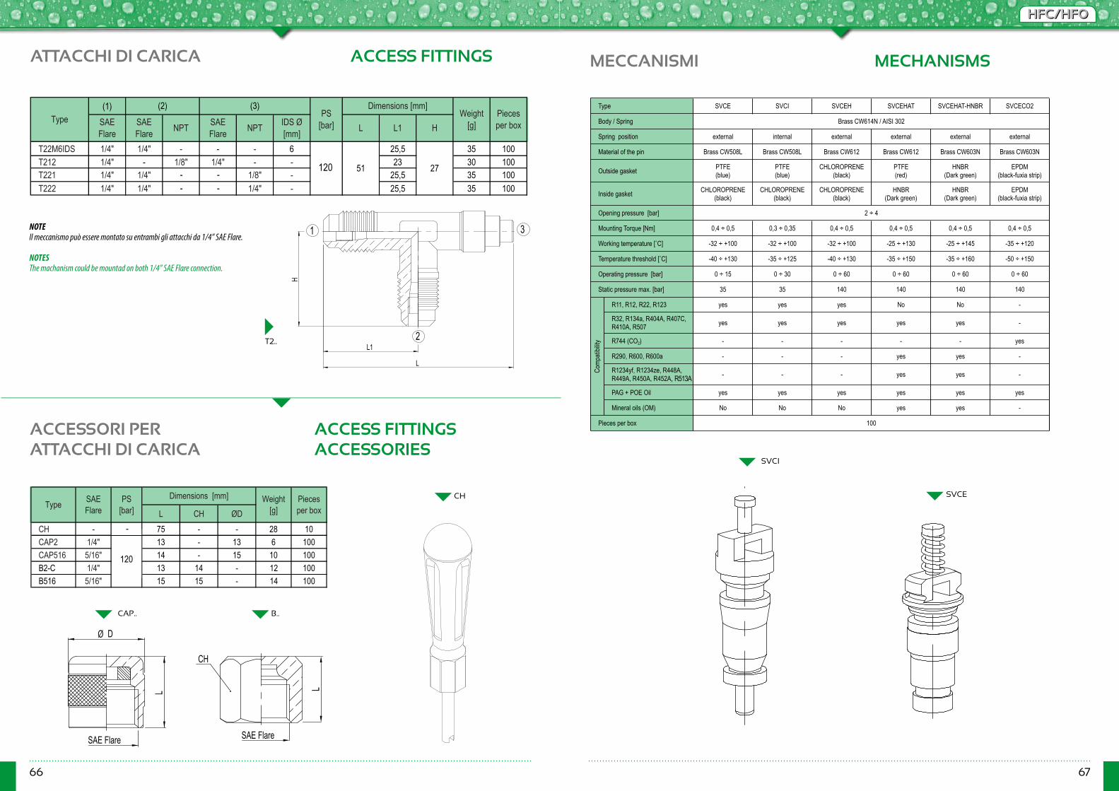
66 67
HFC/HFOHFC/HFO
MECCANISMI MECHANISMS
(1)
T22M6IDS 1/4" 1/4" - - - 6 25,5 35 100T212 1/4" - 1/8" 1/4" - - 23 30 100T221 1/4" 1/4" - - 1/8" - 25,5 35 100T222 1/4" 1/4" - - 1/4" - 25,5 35 100
Pieces per box
Dimensions [mm]
LSAE Flare L1IDS Ø
[mm]
Note: Il meccanismo può essere montato su entrambi gli attacchi da 1/4" SAE FlareNotes : The mechanism could be mounted on both 1/4” SAE Flare connection
NPTPS
[bar]NPTSAE Flare
(2)SAE Flare
(3)Type
45
Weight [g]H
51 27
SVCI
SVCE
NOTEIl meccanismo può essere montato su entrambi gli attacchi da 1/4” SAE Flare.
NOTESThe machanism could be mountad on both 1/4” SAE Flare connection.
L1
L
H
2
1 3
ATTACCHI DI CARICA ACCESS FITTINGS
CH
Ø D
L
SAE Flare SAE Flare
L
ACCESSORI PERATTACCHI DI CARICA
ACCESS FITTINGS ACCESSORIES
B..CAP..
CH
T2..
120
L CH ØDCH - 75 - - 28 10CAP2 1/4" 13 - 13 6 100CAP516 5/16" 14 - 15 10 100B2-C 1/4" 13 14 - 12 100B516 5/16" 15 15 - 14 100
120
45
SAE Flare
PS [bar]
Dimensions [mm] Weight[g]
Pieces per boxType
120
-
SVCE SVCI SVCEH SVCEHAT SVCEHAT-HNBR SVCECO2
external internal external external external external
Brass CW508L Brass CW508L Brass CW612 Brass CW612 Brass CW603N Brass CW603N
PTFE (blue)
PTFE (blue)
CHLOROPRENE (black)
PTFE (red)
HNBR (Dark green)
EPDM (black-fuxia strip)
CHLOROPRENE (black)
CHLOROPRENE (black)
CHLOROPRENE (black)
HNBR (Dark green)
HNBR (Dark green)
EPDM (black-fuxia strip)
0,4 ÷ 0,5 0,3 ÷ 0,35 0,4 ÷ 0,5 0,4 ÷ 0,5 0,4 ÷ 0,5 0,4 ÷ 0,5
-32 ÷ +100 -32 ÷ +100 -32 ÷ +100 -25 ÷ +130 -25 ÷ +145 -35 ÷ +120
-40 ÷ +130 -35 ÷ +125 -40 ÷ +130 -35 ÷ +150 -35 ÷ +160 -50 ÷ +150
0 ÷ 15 0 ÷ 30 0 ÷ 60 0 ÷ 60 0 ÷ 60 0 ÷ 60
35 35 140 140 140 140
R11, R12, R22, R123 yes yes yes No No -
R32, R134a, R404A, R407C, R410A, R507 yes yes yes yes yes -
R744 (CO2) - - - - - yes
R290, R600, R600a - - - yes yes -
R1234yf, R1234ze, R448A, R449A, R450A, R452A - - - yes yes -
PAG + POE Oil yes yes yes yes yes yes
Mineral oils (OM) No No No yes yes -
Brass CW614N / AISI 302
2 ÷ 4
100
Outside gasket
Mounting Torque [Nm]
Temperature threshold [˚C]
Comp
atibil
ity
Working temperature [˚C]
Operating pressure [bar]
Static pressure max. [bar]
Type
Body / Spring
Pieces per box
Opening pressure [bar]
Inside gasket
Spring position
Material of the pin
, R513A
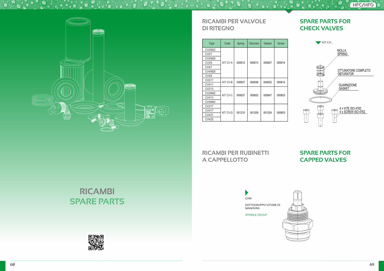
68 69
HFC/HFOHFC/HFO
RICAMBISPARE PARTS
RICAMBI PER VALVOLEDI RITEGNO
RICAMBI PER RUBINETTIA CAPPELLOTTO
SPARE PARTS FORCHECK VALVES
SPARE PARTS FORCAPPED VALVES
Type Code Spring Obturator Gasket Screw
CV2/M22CV2/7CV2/M28CV2/9CV4/7CV4/M28CV4/9CV2/11CV4/11CV2/13CV2/M42CV4/13CV4/M42CV2/17CV4/17CV4/21CV4/25
KIT CV-D 001210 001209 001204 000653
KIT CV-B 000637 000638 000632 000614
KIT CV-A 000612 000613 000607 000614
KIT CV-C 000637 000652 000647 000653
MOLLASPRING
OTTURATORE COMPLETOOBTURATOR
GUARNIZIONEGASKET
4 x VITE ISO 47624 x SCREW ISO 4762
GVM
SOTTOGRUPPO VITONE DI MANOVRA
SPINDLE GROUP
KIT CV-..
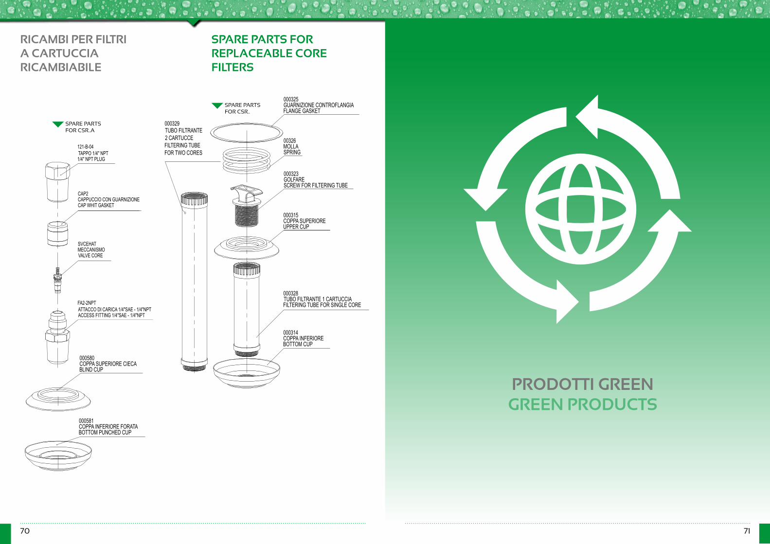
70 71
RICAMBI PER FILTRI A CARTUCCIA RICAMBIABILE
SPARE PARTS FORREPLACEABLE COREFILTERS
000325GUARNIZIONE CONTROFLANGIAFLANGE GASKET
00326MOLLASPRING
000323GOLFARESCREW FOR FILTERING TUBE
000315COPPA SUPERIOREUPPER CUP
000328 TUBO FILTRANTE 1 CARTUCCIAFILTERING TUBE FOR SINGLE CORE
000314COPPA INFERIORE BOTTOM CUP
000329TUBO FILTRANTE 2 CARTUCCEFILTERING TUBE FOR TWO CORES
000580COPPA SUPERIORE CIECABLIND CUP
000581COPPA INFERIORE FORATABOTTOM PUNCHED CUP
121-B-04TAPPO 1/4" NPT1/4" NPT PLUG
SVCEHATMECCANISMOVALVE CORE
FA2-2NPTATTACCO DI CARICA 1/4"SAE - 1/4"NPTACCESS FITTING 1/4"SAE - 1/4"NPT
CAP2CAPPUCCIO CON GUARNIZIONECAP WHIT GASKET
SPARE PARTSFOR CSR..
SPARE PARTSFOR CSR..A
PRODOTTI GREENGREEN PRODUCTS
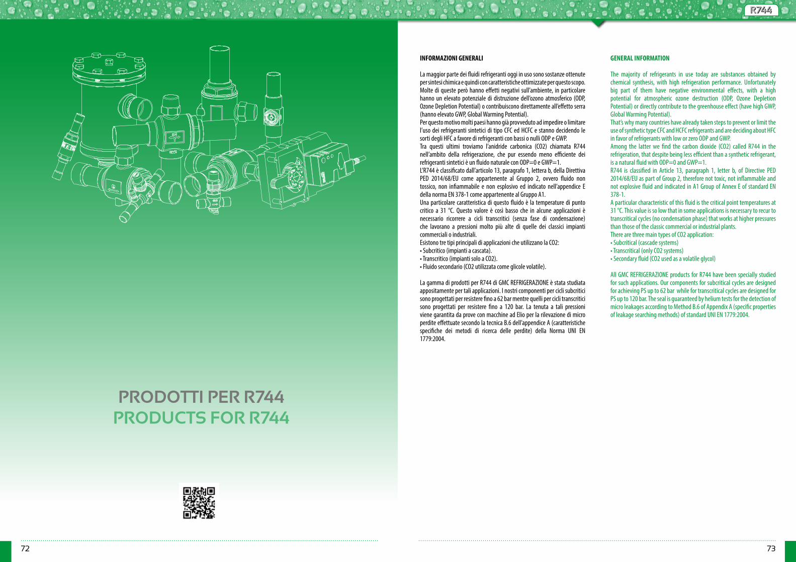
72 73
R744R744
PRODOTTI PER R744PRODUCTS FOR R744
INFORMAZIONI GENERALI
La maggior parte dei fluidi refrigeranti oggi in uso sono sostanze ottenute per sintesi chimica e quindi con caratteristiche ottimizzate per questo scopo. Molte di queste però hanno effetti negativi sull’ambiente, in particolare hanno un elevato potenziale di distruzione dell’ozono atmosferico (ODP, Ozone Depletion Potential) o contribuiscono direttamente all’effetto serra (hanno elevato GWP, Global Warming Potential).Per questo motivo molti paesi hanno già provveduto ad impedire o limitare l’uso dei refrigeranti sintetici di tipo CFC ed HCFC e stanno decidendo le sorti degli HFC a favore di refrigeranti con bassi o nulli ODP e GWP.Tra questi ultimi troviamo l’anidride carbonica (CO2) chiamata R744 nell’ambito della refrigerazione, che pur essendo meno efficiente dei refrigeranti sintetici è un fluido naturale con ODP=0 e GWP=1.L’R744 è classificato dall’articolo 13, paragrafo 1, lettera b, della Direttiva PED 2014/68/EU come appartenente al Gruppo 2, ovvero fluido non tossico, non infiammabile e non esplosivo ed indicato nell’appendice E della norma EN 378-1 come appartenente al Gruppo A1.Una particolare caratteristica di questo fluido è la temperature di punto critico a 31 °C. Questo valore è così basso che in alcune applicazioni è necessario ricorrere a cicli transcritici (senza fase di condensazione) che lavorano a pressioni molto più alte di quelle dei classici impianti commerciali o industriali.Esistono tre tipi principali di applicazioni che utilizzano la CO2: • Subcritico (impianti a cascata).• Transcritico (impianti solo a CO2).• Fluido secondario (CO2 utilizzata come glicole volatile).
La gamma di prodotti per R744 di GMC REFRIGERAZIONE è stata studiata appositamente per tali applicazioni. I nostri componenti per cicli subcritici sono progettati per resistere fino a 62 bar mentre quelli per cicli transcritici sono progettati per resistere fino a 120 bar. La tenuta a tali pressioni viene garantita da prove con macchine ad Elio per la rilevazione di micro perdite effettuate secondo la tecnica B.6 dell’appendice A (caratteristiche specifiche dei metodi di ricerca delle perdite) della Norma UNI EN 1779:2004.
GENERAL INFORMATION
The majority of refrigerants in use today are substances obtained by chemical synthesis, with high refrigeration performance. Unfortunately big part of them have negative environmental effects, with a high potential for atmospheric ozone destruction (ODP, Ozone Depletion Potential) or directly contribute to the greenhouse effect (have high GWP, Global Warming Potential).That’s why many countries have already taken steps to prevent or limit the use of synthetic type CFC and HCFC refrigerants and are deciding about HFC in favor of refrigerants with low or zero ODP and GWP.Among the latter we find the carbon dioxide (CO2) called R744 in the refrigeration, that despite being less efficient than a synthetic refrigerant, is a natural fluid with ODP=0 and GWP=1.R744 is classified in Article 13, paragraph 1, letter b, of Directive PED 2014/68/EU as part of Group 2, therefore not toxic, not inflammable and not explosive fluid and indicated in A1 Group of Annex E of standard EN 378-1.A particular characteristic of this fluid is the critical point temperatures at 31 °C. This value is so low that in some applications is necessary to recur to transcritical cycles (no condensation phase) that works at higher pressures than those of the classic commercial or industrial plants.There are three main types of CO2 application:• Subcritical (cascade systems)• Transcritical (only CO2 systems)• Secondary fluid (CO2 used as a volatile glycol)
All GMC REFRIGERAZIONE products for R744 have been specially studied for such applications. Our components for subcritical cycles are designed for achieving PS up to 62 bar while for transcritical cycles are designed for PS up to 120 bar. The seal is guaranteed by helium tests for the detection of micro leakages according to Method B.6 of Appendix A (specific properties of leakage searching methods) of standard UNI EN 1779:2004.
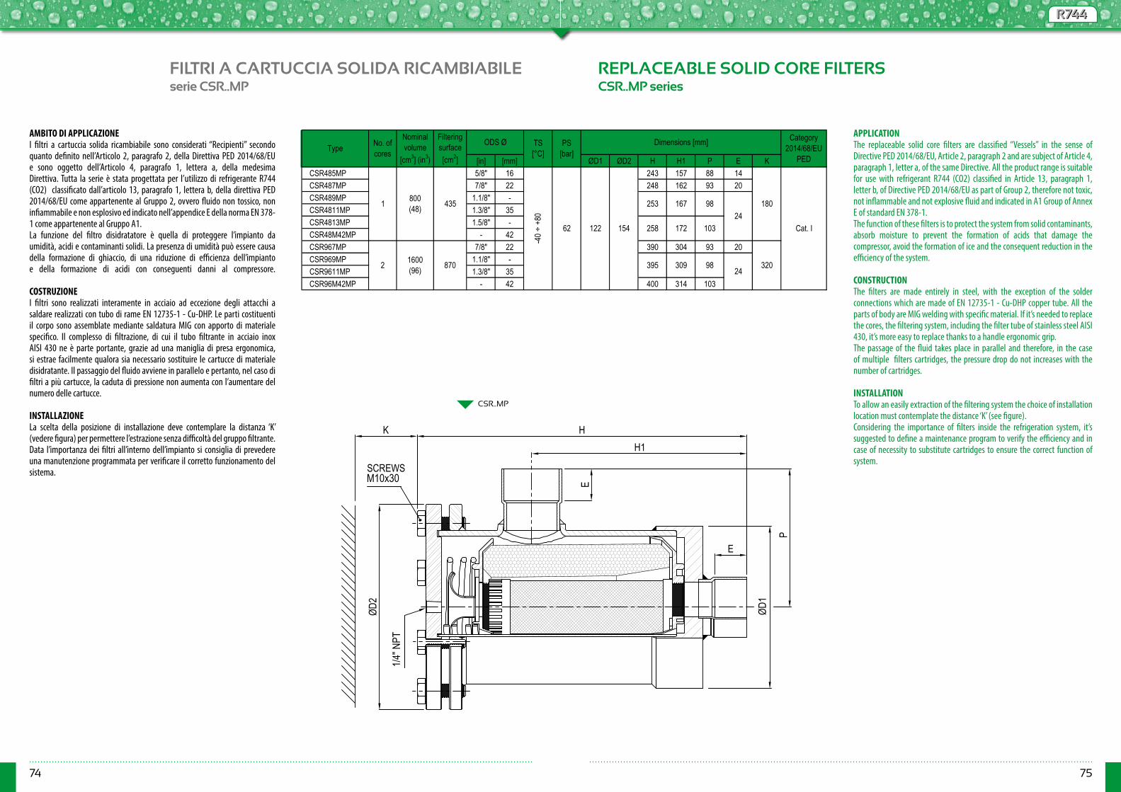
74 75
R744R744
FILTRI A CARTUCCIA SOLIDA RICAMBIABILE REPLACEABLE SOLID CORE FILTERSserie CSR..MP CSR..MP series
CSR..MP
[in] [mm] ØD1 ØD2 H H1 P E KCSR485MP 5/8" 16 243 157 88 14CSR487MP 7/8" 22 248 162 93 20CSR489MP 1.1/8" -CSR4811MP 1.3/8" 35CSR4813MP 1.5/8" -CSR48M42MP - 42CSR967MP 7/8" 22 390 304 93 20CSR969MP 1.1/8" -CSR9611MP 1.3/8" 35CSR96M42MP - 42 400 314 103
Cat. I24
253
258
Category 2014/68/EU
PED
24395
98
172 103
2
1 800 (48)
-40 ÷
+80
62
Filtering surface [cm2]
ODS Ø
180
320
122 154
309 98
167
Type No. of cores
Nominal volume
[cm3] (in3)
TS [°C]
PS [bar]
Dimensions [mm]
1600 (96) 870
435
AMBITO DI APPLICAZIONEI filtri a cartuccia solida ricambiabile sono considerati “Recipienti” secondo quanto definito nell’Articolo 2, paragrafo 2, della Direttiva PED 2014/68/EUe sono oggetto dell’Articolo 4, paragrafo 1, lettera a, della medesima Direttiva. Tutta la serie è stata progettata per l’utilizzo di refrigerante R744 (CO2) classificato dall’articolo 13, paragrafo 1, lettera b, della direttiva PED 2014/68/EU come appartenente al Gruppo 2, ovvero fluido non tossico, non infiammabile e non esplosivo ed indicato nell’appendice E della norma EN 378-1 come appartenente al Gruppo A1.La funzione del filtro disidratatore è quella di proteggere l’impianto da umidità, acidi e contaminanti solidi. La presenza di umidità può essere causa della formazione di ghiaccio, di una riduzione di efficienza dell’impianto e della formazione di acidi con conseguenti danni al compressore.
COSTRUZIONEI filtri sono realizzati interamente in acciaio ad eccezione degli attacchi a saldare realizzati con tubo di rame EN 12735-1 - Cu-DHP. Le parti costituenti il corpo sono assemblate mediante saldatura MIG con apporto di materiale specifico. Il complesso di filtrazione, di cui il tubo filtrante in acciaio inox AISI 430 ne è parte portante, grazie ad una maniglia di presa ergonomica, si estrae facilmente qualora sia necessario sostituire le cartucce di materiale disidratante. Il passaggio del fluido avviene in parallelo e pertanto, nel caso di filtri a più cartucce, la caduta di pressione non aumenta con l’aumentare del numero delle cartucce. INSTALLAZIONELa scelta della posizione di installazione deve contemplare la distanza ‘K’ (vedere figura) per permettere l’estrazione senza difficoltà del gruppo filtrante.Data l’importanza dei filtri all’interno dell’impianto si consiglia di prevedere una manutenzione programmata per verificare il corretto funzionamento del sistema.
APPLICATIONThe replaceable solid core filters are classified “Vessels” in the sense of Directive PED 2014/68/EU, Article 2, paragraph 2 and are subject of Article 4, paragraph 1, letter a, of the same Directive. All the product range is suitable for use with refrigerant R744 (CO2) classified in Article 13, paragraph 1, letter b, of Directive PED 2014/68/EU as part of Group 2, therefore not toxic, not inflammable and not explosive fluid and indicated in A1 Group of Annex E of standard EN 378-1.The function of these filters is to protect the system from solid contaminants, absorb moisture to prevent the formation of acids that damage the compressor, avoid the formation of ice and the consequent reduction in the efficiency of the system. CONSTRUCTIONThe filters are made entirely in steel, with the exception of the solder connections which are made of EN 12735-1 - Cu-DHP copper tube. All the parts of body are MIG welding with specific material. If it’s needed to replace the cores, the filtering system, including the filter tube of stainless steel AISI 430, it’s more easy to replace thanks to a handle ergonomic grip.The passage of the fluid takes place in parallel and therefore, in the case of multiple filters cartridges, the pressure drop do not increases with the number of cartridges.
INSTALLATIONTo allow an easily extraction of the filtering system the choice of installation location must contemplate the distance ‘K’ (see figure).Considering the importance of filters inside the refrigeration system, it’s suggested to define a maintenance program to verify the efficiency and in case of necessity to substitute cartridges to ensure the correct function of system.
H1
E
P
E
H
ØD2
K
ØD1
SCREWSM10x30
1/4" N
PT
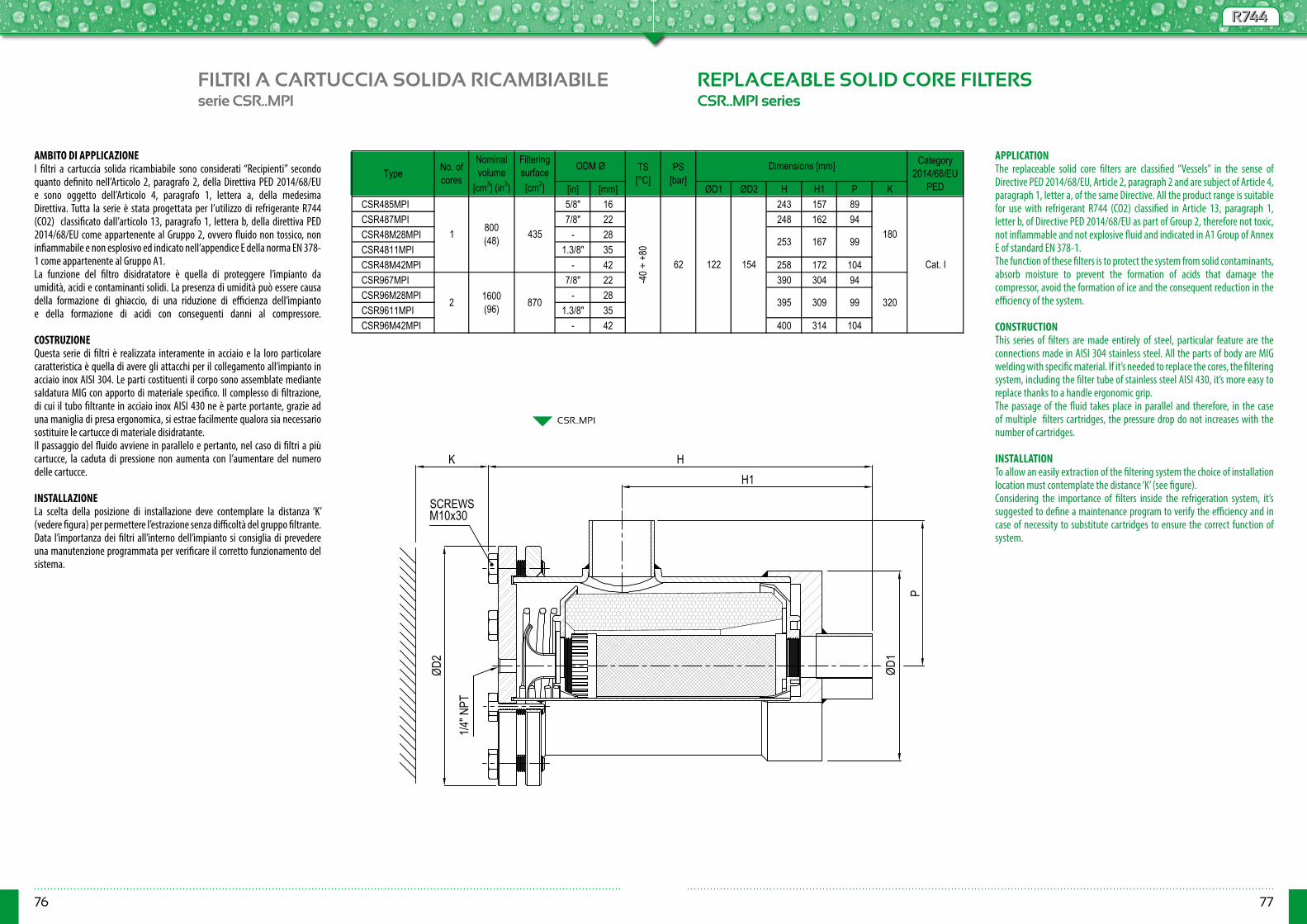
76 77
R744R744
FILTRI A CARTUCCIA SOLIDA RICAMBIABILE REPLACEABLE SOLID CORE FILTERSserie CSR..MPI CSR..MPI series
CSR..MPI
[in] [mm] ØD1 ØD2 H H1 P KCSR485MPI 5/8" 16 243 157 89CSR487MPI 7/8" 22 248 162 94CSR48M28MPI - 28CSR4811MPI 1.3/8" 35CSR48M42MPI - 42 258 172 104CSR967MPI 7/8" 22 390 304 94CSR96M28MPI - 28CSR9611MPI 1.3/8" 35CSR96M42MPI - 42 400 314 104
99
167 99
Type No. of cores
Nominal volume
[cm3] (in3)
TS [°C]
PS [bar]
1600 (96) 870
435
Filtering surface [cm2]
ODM Ø
180
320
122 154
309
Cat. I
253
Category 2014/68/EU
PED
3952
1 800 (48)
-40 ÷
+80
62
Dimensions [mm]AMBITO DI APPLICAZIONEI filtri a cartuccia solida ricambiabile sono considerati “Recipienti” secondo quanto definito nell’Articolo 2, paragrafo 2, della Direttiva PED 2014/68/EU e sono oggetto dell’Articolo 4, paragrafo 1, lettera a, della medesima Direttiva. Tutta la serie è stata progettata per l’utilizzo di refrigerante R744 (CO2) classificato dall’articolo 13, paragrafo 1, lettera b, della direttiva PED 2014/68/EU come appartenente al Gruppo 2, ovvero fluido non tossico, non infiammabile e non esplosivo ed indicato nell’appendice E della norma EN 378-1 come appartenente al Gruppo A1.La funzione del filtro disidratatore è quella di proteggere l’impianto da umidità, acidi e contaminanti solidi. La presenza di umidità può essere causa della formazione di ghiaccio, di una riduzione di efficienza dell’impianto e della formazione di acidi con conseguenti danni al compressore.
COSTRUZIONEQuesta serie di filtri è realizzata interamente in acciaio e la loro particolare caratteristica è quella di avere gli attacchi per il collegamento all’impianto in acciaio inox AISI 304. Le parti costituenti il corpo sono assemblate mediante saldatura MIG con apporto di materiale specifico. Il complesso di filtrazione, di cui il tubo filtrante in acciaio inox AISI 430 ne è parte portante, grazie ad una maniglia di presa ergonomica, si estrae facilmente qualora sia necessario sostituire le cartucce di materiale disidratante. Il passaggio del fluido avviene in parallelo e pertanto, nel caso di filtri a più cartucce, la caduta di pressione non aumenta con l’aumentare del numero delle cartucce. INSTALLAZIONELa scelta della posizione di installazione deve contemplare la distanza ‘K’ (vedere figura) per permettere l’estrazione senza difficoltà del gruppo filtrante.Data l’importanza dei filtri all’interno dell’impianto si consiglia di prevedere una manutenzione programmata per verificare il corretto funzionamento del sistema.
APPLICATIONThe replaceable solid core filters are classified “Vessels” in the sense of Directive PED 2014/68/EU, Article 2, paragraph 2 and are subject of Article 4, paragraph 1, letter a, of the same Directive. All the product range is suitable for use with refrigerant R744 (CO2) classified in Article 13, paragraph 1, letter b, of Directive PED 2014/68/EU as part of Group 2, therefore not toxic, not inflammable and not explosive fluid and indicated in A1 Group of Annex E of standard EN 378-1.The function of these filters is to protect the system from solid contaminants, absorb moisture to prevent the formation of acids that damage the compressor, avoid the formation of ice and the consequent reduction in the efficiency of the system. CONSTRUCTIONThis series of filters are made entirely of steel, particular feature are the connections made in AISI 304 stainless steel. All the parts of body are MIG welding with specific material. If it’s needed to replace the cores, the filtering system, including the filter tube of stainless steel AISI 430, it’s more easy to replace thanks to a handle ergonomic grip.The passage of the fluid takes place in parallel and therefore, in the case of multiple filters cartridges, the pressure drop do not increases with the number of cartridges.
INSTALLATIONTo allow an easily extraction of the filtering system the choice of installation location must contemplate the distance ‘K’ (see figure).Considering the importance of filters inside the refrigeration system, it’s suggested to define a maintenance program to verify the efficiency and in case of necessity to substitute cartridges to ensure the correct function of system.
H1
P
H
ØD2
K
ØD1
SCREWSM10x30
1/4" N
PT
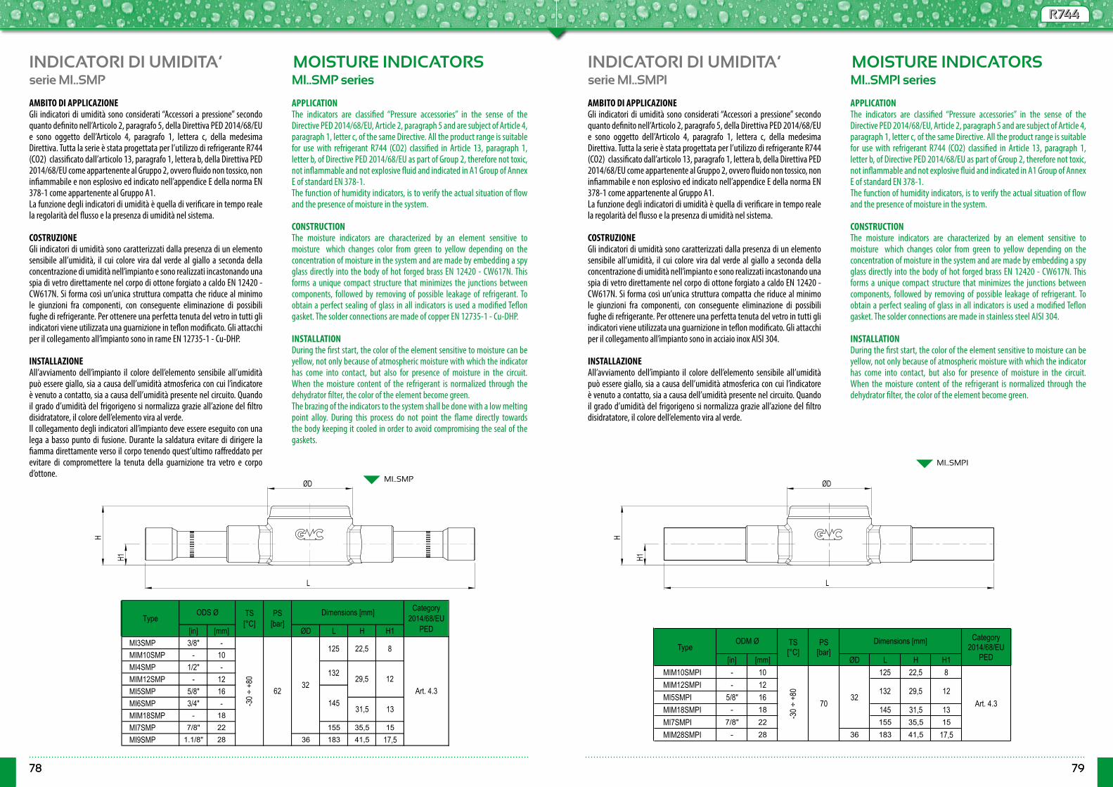
78 79
R744R744
78 79
INDICATORI DI UMIDITA’ INDICATORI DI UMIDITA’MOISTURE INDICATORS MOISTURE INDICATORSserie MI..SMP serie MI..SMPIMI..SMP series MI..SMPI series
MI..SMP
MI..SMPI
[in] [mm] ØD L H H1MI3SMP 3/8" -MIM10SMP - 10MI4SMP 1/2" -MIM12SMP - 12MI5SMP 5/8" 16MI6SMP 3/4" -MIM18SMP - 18MI7SMP 7/8" 22 155 35,5 15MI9SMP 1.1/8" 28 36 183 41,5 17,5
31,5
29,5
22,5
Art. 4.3
TypeODS Ø PS
[bar]Dimensions [mm] Category
2014/68/EU PED
TS [°C]
12
13
-30 ÷
+80
8
6232
125
132
145
[in] [mm] ØD L H H1MIM10SMPI - 10 125 22,5 8MIM12SMPI - 12MI5SMPI 5/8" 16MIM18SMPI - 18 145 31,5 13MI7SMPI 7/8" 22 155 35,5 15
MIM28SMPI - 28 36 183 41,5 17,5
TypeODM Ø PS
[bar]Dimensions [mm] Category
2014/68/EU PED
TS [°C]
12
-30 ÷
+80
7032
Art. 4.3132 29,5
AMBITO DI APPLICAZIONEGli indicatori di umidità sono considerati “Accessori a pressione” secondo quanto definito nell’Articolo 2, paragrafo 5, della Direttiva PED 2014/68/EU e sono oggetto dell’Articolo 4, paragrafo 1, lettera c, della medesima Direttiva. Tutta la serie è stata progettata per l’utilizzo di refrigerante R744 (CO2) classificato dall’articolo 13, paragrafo 1, lettera b, della Direttiva PED 2014/68/EU come appartenente al Gruppo 2, ovvero fluido non tossico, non infiammabile e non esplosivo ed indicato nell’appendice E della norma EN 378-1 come appartenente al Gruppo A1.La funzione degli indicatori di umidità è quella di verificare in tempo reale la regolarità del flusso e la presenza di umidità nel sistema.
COSTRUZIONEGli indicatori di umidità sono caratterizzati dalla presenza di un elemento sensibile all’umidità, il cui colore vira dal verde al giallo a seconda della concentrazione di umidità nell’impianto e sono realizzati incastonando una spia di vetro direttamente nel corpo di ottone forgiato a caldo EN 12420 - CW617N. Si forma così un’unica struttura compatta che riduce al minimo le giunzioni fra componenti, con conseguente eliminazione di possibili fughe di refrigerante. Per ottenere una perfetta tenuta del vetro in tutti gli indicatori viene utilizzata una guarnizione in teflon modificato. Gli attacchi per il collegamento all’impianto sono in rame EN 12735-1 - Cu-DHP. INSTALLAZIONEAll’avviamento dell’impianto il colore dell’elemento sensibile all’umidità può essere giallo, sia a causa dell’umidità atmosferica con cui l’indicatore è venuto a contatto, sia a causa dell’umidità presente nel circuito. Quando il grado d’umidità del frigorigeno si normalizza grazie all’azione del filtro disidratatore, il colore dell’elemento vira al verde.Il collegamento degli indicatori all’impianto deve essere eseguito con una lega a basso punto di fusione. Durante la saldatura evitare di dirigere la fiamma direttamente verso il corpo tenendo quest’ultimo raffreddato per evitare di compromettere la tenuta della guarnizione tra vetro e corpo d’ottone.
AMBITO DI APPLICAZIONEGli indicatori di umidità sono considerati “Accessori a pressione” secondo quanto definito nell’Articolo 2, paragrafo 5, della Direttiva PED 2014/68/EU e sono oggetto dell’Articolo 4, paragrafo 1, lettera c, della medesima Direttiva. Tutta la serie è stata progettata per l’utilizzo di refrigerante R744 (CO2) classificato dall’articolo 13, paragrafo 1, lettera b, della Direttiva PED 2014/68/EU come appartenente al Gruppo 2, ovvero fluido non tossico, non infiammabile e non esplosivo ed indicato nell’appendice E della norma EN 378-1 come appartenente al Gruppo A1.La funzione degli indicatori di umidità è quella di verificare in tempo reale la regolarità del flusso e la presenza di umidità nel sistema.
COSTRUZIONEGli indicatori di umidità sono caratterizzati dalla presenza di un elemento sensibile all’umidità, il cui colore vira dal verde al giallo a seconda della concentrazione di umidità nell’impianto e sono realizzati incastonando una spia di vetro direttamente nel corpo di ottone forgiato a caldo EN 12420 - CW617N. Si forma così un’unica struttura compatta che riduce al minimo le giunzioni fra componenti, con conseguente eliminazione di possibili fughe di refrigerante. Per ottenere una perfetta tenuta del vetro in tutti gli indicatori viene utilizzata una guarnizione in teflon modificato. Gli attacchi per il collegamento all’impianto sono in acciaio inox AISI 304. INSTALLAZIONEAll’avviamento dell’impianto il colore dell’elemento sensibile all’umidità può essere giallo, sia a causa dell’umidità atmosferica con cui l’indicatore è venuto a contatto, sia a causa dell’umidità presente nel circuito. Quando il grado d’umidità del frigorigeno si normalizza grazie all’azione del filtro disidratatore, il colore dell’elemento vira al verde.
APPLICATIONThe indicators are classified “Pressure accessories” in the sense of the Directive PED 2014/68/EU, Article 2, paragraph 5 and are subject of Article 4, paragraph 1, letter c, of the same Directive. All the product range is suitable for use with refrigerant R744 (CO2) classified in Article 13, paragraph 1, letter b, of Directive PED 2014/68/EU as part of Group 2, therefore not toxic, not inflammable and not explosive fluid and indicated in A1 Group of Annex E of standard EN 378-1.The function of humidity indicators, is to verify the actual situation of flow and the presence of moisture in the system. CONSTRUCTIONThe moisture indicators are characterized by an element sensitive to moisture which changes color from green to yellow depending on the concentration of moisture in the system and are made by embedding a spy glass directly into the body of hot forged brass EN 12420 - CW617N. This forms a unique compact structure that minimizes the junctions between components, followed by removing of possible leakage of refrigerant. To obtain a perfect sealing of glass in all indicators is used a modified Teflon gasket. The solder connections are made of copper EN 12735-1 - Cu-DHP.
INSTALLATIONDuring the first start, the color of the element sensitive to moisture can be yellow, not only because of atmospheric moisture with which the indicator has come into contact, but also for presence of moisture in the circuit. When the moisture content of the refrigerant is normalized through the dehydrator filter, the color of the element become green. The brazing of the indicators to the system shall be done with a low melting point alloy. During this process do not point the flame directly towards the body keeping it cooled in order to avoid compromising the seal of the gaskets.
APPLICATIONThe indicators are classified “Pressure accessories” in the sense of the Directive PED 2014/68/EU, Article 2, paragraph 5 and are subject of Article 4, paragraph 1, letter c, of the same Directive. All the product range is suitable for use with refrigerant R744 (CO2) classified in Article 13, paragraph 1, letter b, of Directive PED 2014/68/EU as part of Group 2, therefore not toxic, not inflammable and not explosive fluid and indicated in A1 Group of Annex E of standard EN 378-1.The function of humidity indicators, is to verify the actual situation of flow and the presence of moisture in the system. CONSTRUCTIONThe moisture indicators are characterized by an element sensitive to moisture which changes color from green to yellow depending on the concentration of moisture in the system and are made by embedding a spy glass directly into the body of hot forged brass EN 12420 - CW617N. This forms a unique compact structure that minimizes the junctions between components, followed by removing of possible leakage of refrigerant. To obtain a perfect sealing of glass in all indicators is used a modified Teflon gasket. The solder connections are made in stainless steel AISI 304. INSTALLATIONDuring the first start, the color of the element sensitive to moisture can be yellow, not only because of atmospheric moisture with which the indicator has come into contact, but also for presence of moisture in the circuit. When the moisture content of the refrigerant is normalized through the dehydrator filter, the color of the element become green.
ØD
H1
H
L
ØD
H1
H
L
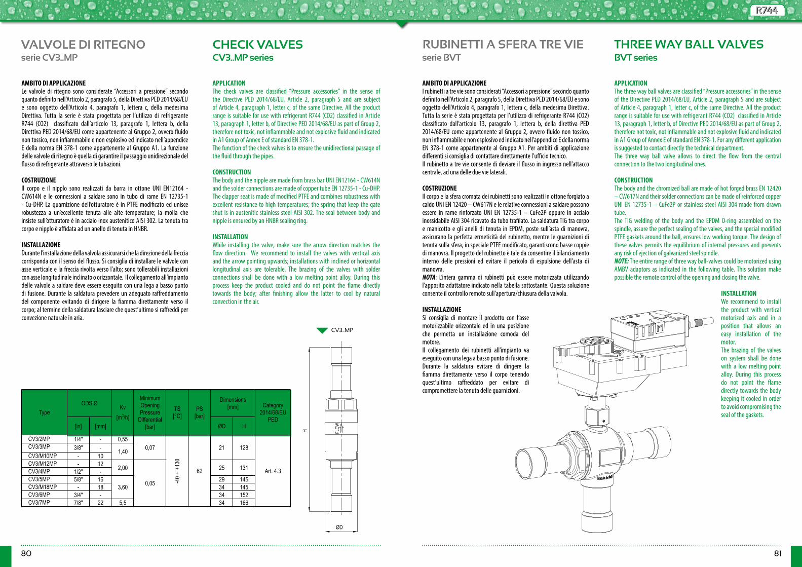
80 81
R744R744
VALVOLE DI RITEGNO CHECK VALVESserie CV3..MP serie BVTCV3..MP series BVT series
CV3..MP
[in] [mm] ØD H
CV3/2MP 1/4" - 0,55CV3/3MP 3/8" -CV3/M10MP - 10CV3/M12MP - 12CV3/4MP 1/2" -CV3/5MP 5/8" 16 29 145CV3/M18MP - 18 34 145CV3/6MP 3/4" - 34 152CV3/7MP 7/8" 22 5,5 34 166
Dimensions [mm]
25 131
TypeKv
[m3/h]
MinimumOpeningPressure
Differential[bar]
ODS Ø
0,05
0,07
3,60
Category 2014/68/EU
PED
1,40
2,00
-40 ÷
+13
0
62
21 128
Art. 4.3
TS [°C]
PS [bar]
AMBITO DI APPLICAZIONELe valvole di ritegno sono considerate “Accessori a pressione” secondo quanto definito nell’Articolo 2, paragrafo 5, della Direttiva PED 2014/68/EU e sono oggetto dell’Articolo 4, paragrafo 1, lettera c, della medesima Direttiva. Tutta la serie è stata progettata per l’utilizzo di refrigerante R744 (CO2) classificato dall’articolo 13, paragrafo 1, lettera b, della Direttiva PED 2014/68/EU come appartenente al Gruppo 2, ovvero fluido non tossico, non infiammabile e non esplosivo ed indicato nell’appendice E della norma EN 378-1 come appartenente al Gruppo A1. La funzione delle valvole di ritegno è quella di garantire il passaggio unidirezionale del flusso di refrigerante attraverso le tubazioni.
COSTRUZIONEIl corpo e il nipplo sono realizzati da barra in ottone UNI EN12164 - CW614N e le connessioni a saldare sono in tubo di rame EN 12735-1 - Cu-DHP. La guarnizione dell’otturatore è in PTFE modificato ed unisce robustezza a un’eccellente tenuta alle alte temperature; la molla che insiste sull’otturatore è in acciaio inox austenitico AISI 302. La tenuta tra corpo e nipplo è affidata ad un anello di tenuta in HNBR. INSTALLAZIONEDurante l’installazione della valvola assicurarsi che la direzione della freccia corrisponda con il senso del flusso. Si consiglia di installare le valvole con asse verticale e la freccia rivolta verso l’alto; sono tollerabili installazioni con asse longitudinale inclinato o orizzontale. Il collegamento all’impianto delle valvole a saldare deve essere eseguito con una lega a basso punto di fusione. Durante la saldatura prevedere un adeguato raffreddamento del componente evitando di dirigere la fiamma direttamente verso il corpo; al termine della saldatura lasciare che quest’ultimo si raffreddi per convezione naturale in aria.
APPLICATIONThe check valves are classified “Pressure accessories” in the sense of the Directive PED 2014/68/EU, Article 2, paragraph 5 and are subject of Article 4, paragraph 1, letter c, of the same Directive. All the product range is suitable for use with refrigerant R744 (CO2) classified in Article 13, paragraph 1, letter b, of Directive PED 2014/68/EU as part of Group 2, therefore not toxic, not inflammable and not explosive fluid and indicated in A1 Group of Annex E of standard EN 378-1.The function of the check valves is to ensure the unidirectional passage of the fluid through the pipes. CONSTRUCTIONThe body and the nipple are made from brass bar UNI EN12164 - CW614N and the solder connections are made of copper tube EN 12735-1 - Cu-DHP. The clapper seat is made of modified PTFE and combines robustness with excellent resistance to high temperatures; the spring that keep the gate shut is in austenitic stainless steel AISI 302. The seal between body and nipple is ensured by an HNBR sealing ring.
INSTALLATIONWhile installing the valve, make sure the arrow direction matches the flow direction. We recommend to install the valves with vertical axis and the arrow pointing upwards; installations with inclined or horizontal longitudinal axis are tolerable. The brazing of the valves with solder connections shall be done with a low melting point alloy. During this process keep the product cooled and do not point the flame directly towards the body; after finishing allow the latter to cool by natural convection in the air.
ØD
H FLO
W
RUBINETTI A SFERA TRE VIE THREE WAY BALL VALVES
AMBITO DI APPLICAZIONEI rubinetti a tre vie sono considerati “Accessori a pressione” secondo quanto definito nell’Articolo 2, paragrafo 5, della Direttiva PED 2014/68/EU e sono oggetto dell’Articolo 4, paragrafo 1, lettera c, della medesima Direttiva. Tutta la serie è stata progettata per l’utilizzo di refrigerante R744 (CO2) classificato dall’articolo 13, paragrafo 1, lettera b, della direttiva PED 2014/68/EU come appartenente al Gruppo 2, ovvero fluido non tossico, non infiammabile e non esplosivo ed indicato nell’appendice E della norma EN 378-1 come appartenente al Gruppo A1. Per ambiti di applicazione differenti si consiglia di contattare direttamente l’ufficio tecnico.Il rubinetto a tre vie consente di deviare il flusso in ingresso nell’attacco centrale, ad una delle due vie laterali.
COSTRUZIONEIl corpo e la sfera cromata dei rubinetti sono realizzati in ottone forgiato a caldo UNI EN 12420 – CW617N e le relative connessioni a saldare possono essere in rame rinforzato UNI EN 12735-1 – CuFe2P oppure in acciaio inossidabile AISI 304 ricavato da tubo trafilato. La saldatura TIG tra corpo e manicotto e gli anelli di tenuta in EPDM, poste sull’asta di manovra, assicurano la perfetta ermeticità del rubinetto, mentre le guarnizioni di tenuta sulla sfera, in speciale PTFE modificato, garantiscono basse coppie di manovra. Il progetto del rubinetto è tale da consentire il bilanciamento interno delle pressioni ed evitare il pericolo di espulsione dell’asta di manovra.NOTA: L’intera gamma di rubinetti può essere motorizzata utilizzando l’apposito adattatore indicato nella tabella sottostante. Questa soluzione consente il controllo remoto sull’apertura/chiusura della valvola.
INSTALLAZIONESi consiglia di montare il prodotto con l’asse motorizzabile orizzontale ed in una posizione che permetta un installazione comoda del motore.Il collegamento dei rubinetti all’impianto va eseguito con una lega a basso punto di fusione.Durante la saldatura evitare di dirigere la fiamma direttamente verso il corpo tenendo quest’ultimo raffreddato per evitare di compromettere la tenuta delle guarnizioni.
APPLICATIONThe three way ball valves are classified “Pressure accessories” in the sense of the Directive PED 2014/68/EU, Article 2, paragraph 5 and are subject of Article 4, paragraph 1, letter c, of the same Directive. All the product range is suitable for use with refrigerant R744 (CO2) classified in Article 13, paragraph 1, letter b, of Directive PED 2014/68/EU as part of Group 2, therefore not toxic, not inflammable and not explosive fluid and indicated in A1 Group of Annex E of standard EN 378-1. For any different application is suggested to contact directly the technical department.The three way ball valve allows to direct the flow from the central connection to the two longitudinal ones. CONSTRUCTIONThe body and the chromized ball are made of hot forged brass EN 12420 – CW617N and their solder connections can be made of reinforced copper UNI EN 12735-1 – CuFe2P or stainless steel AISI 304 made from drawn tube.The TIG welding of the body and the EPDM O-ring assembled on the spindle, assure the perfect sealing of the valves, and the special modified PTFE gaskets around the ball, ensures low working torque. The design of these valves permits the equilibrium of internal pressures and prevents any risk of ejection of galvanized steel spindle. NOTE: The entire range of three way ball-valves could be motorized using AMBV adaptors as indicated in the following table. This solution make possible the remote control of the opening and closing the valve.
INSTALLATIONWe recommend to install the product with vertical motorized axis and in a position that allows an easy installation of the motor. The brazing of the valves on system shall be done with a low melting point alloy. During this process do not point the flame directly towards the body keeping it cooled in order to avoid compromising the seal of the gaskets.
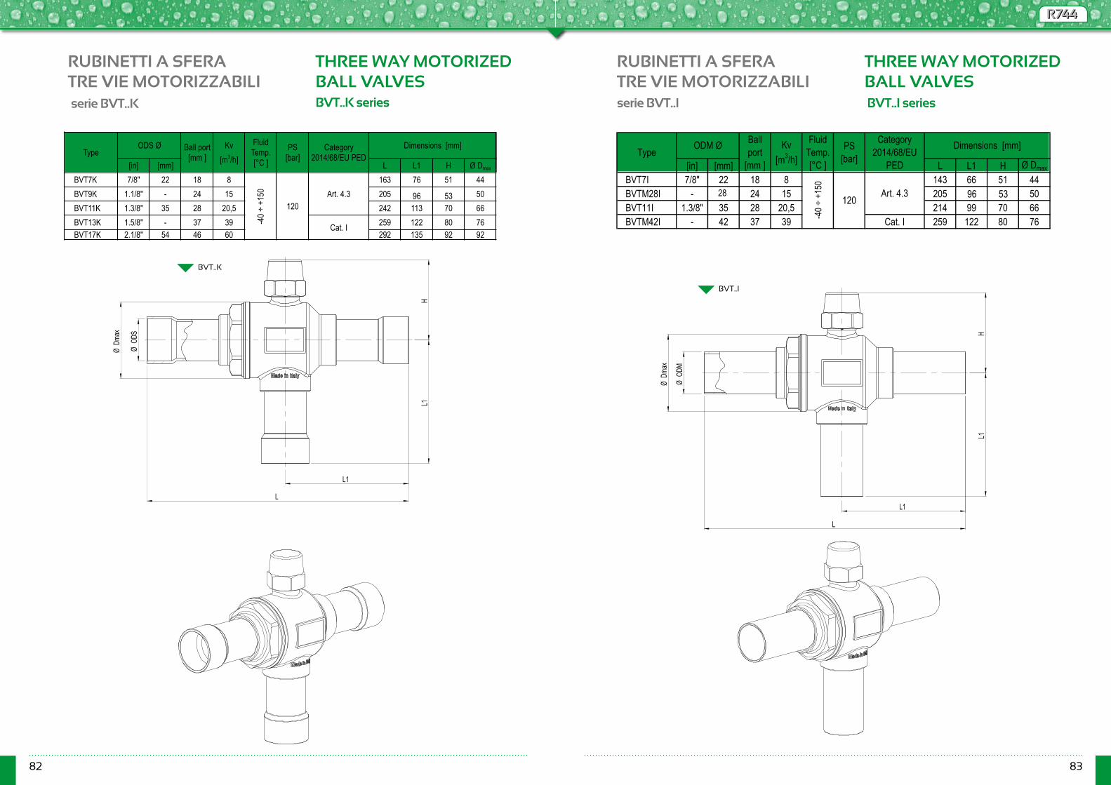
82 83
R744R744
serie BVT..Iserie BVT..K BVT..I series BVT..K series
BVT..K
BVT..I
[in] [mm] L L1 H Ø Dmax
BVT7K 7/8" 22 18 8 163 76 51 44BVT9K 1.1/8" - 24 15 205 96 53 50BVT11K 1.3/8" 35 28 20,5 242 113 70 66BVT13K 1.5/8" - 37 39 259 122 80 76BVT17K 2.1/8" 54 46 60 292 135 92 92
TypeODS Ø Ball port
[mm ]Kv
[m3/h]
Fluid Temp. [°C ]
Art. 4.3
Dimensions [mm]Category2014/68/EU PED
PS[bar]
-40 ÷
+15
0
120
Cat. I
[in] [mm] L L1 H Ø Dmax
BVT7I 7/8" 22 18 8 143 66 51 44BVTM28I - M28 24 15 205 96 53 50BVT11I 1.3/8" 35 28 20,5 214 99 70 66BVTM42I - 42 37 39 Cat. I 259 122 80 76
Dimensions [mm]
-45 ÷
+15
0
120 Art. 4.3
PS[bar]
Category2014/68/EU
PEDType ODM Ø Ball
port [mm ]
Kv[m3/h]
Fluid Temp. [°C ]
RUBINETTI A SFERATRE VIE MOTORIZZABILI
RUBINETTI A SFERATRE VIE MOTORIZZABILI
THREE WAY MOTORIZEDBALL VALVES
THREE WAY MOTORIZEDBALL VALVES
HL1
L1
ØOD
S
ØDm
ax
L
HL1
ØOD
M
ØDm
ax
L
L1
-40 ÷
+15
0
28

84 85
R744R744
Ø d3
Ø d1
Ø d4
45°
sTy
pe L
AA
H1
l5
Flange TYPE
BVT..
Socket set screw M3
CH
AMBV..
BV..
s
Type D
Ø d1
Ø d3
45° A
Ø d4
BV..
BVT.. BVT..K, BVT..I + AMBV.. + ACTUATOR
Running time [s]
Rotation angle
Torque [Nm]
Power Supply Vac
@ 50/60Hz
Power Supply
VDC
Modulating VDC (0)2..10V & On/Off
On/Off H1 H2 L2 L3 P
24 24 SR24A-MF-R SR24A-R
230 - - SR230A-R
24 24 SR24A-MF-R SR24A-R
230 - - SR230A-R
24 24 GR24A-MF-R GR24A-R
230 - - GR230A-R
24 24 GR24A-MF-R GR24A-R
230 - - GR230A-R
24 24 DR24A-SR-7 DR24A-7
230 - - DR230A-7152 13590
120
146 129 72
20
BV17K, BVT17K. AMBV5 -
150
90°
90
124
69
118 9486
98
BV11.BV11K, BV11HP.BVT11K, BVT11I.
AMBV4
PS [bar]
Belimo form fit adapter
Belimo rotary actuator (1) Assembly Dimensions [mm]
67
70
99
104
TypeGMC
actuator adapter
151ZGV-14 40BV13, BVM42. BV13K, BVM42HP.BVT13K, BVTM42I.
BVM18, BV6, BV7.BV6K, BV7K, BVM18HP, BV7HP. BVT7K, BVT7I. AMBV2 ZSV-09 BV9, BVM28.BV9K, BVM28HP.BVT9K, BVTM28I.
RUBINETTI A SFERAMOTORIZZABILI
BALL VALVES WITH ASSEMBLED ADAPTERS
GMC Refrigerazione realizza rubinetti a sfera, due e tre vie, per fluidi HFC/HFO e R744 con adattatore flangiato a Norma ISO 5211 predisposti per l’abbinamento ad attuatori elettromeccanici rotanti dotati di coppia di manovra minima indicata in tabella in relazione alle dimensioni del rubinetto.Gli adattatori premontati sono realizzati in acciaio UNI EN 10277 11SMnPb37 con trattamento superficiale di zincatura e dispongono di una vite di bloccaggio per prevenire l’allentamento della ghiera di ancoraggio al rubinetto dovuto ad eventuali vibrazioni dell’impianto.
GMC Refrigerazione manufactures, two and three ways ball valves, for HFC / HFO and R744 fluids with flanged adapters according to ISO 5211 designed to be combined with rotary electromechanical actuators with minimum operation torque as indicated values basis on the size of ball-valve. The adapters are made in steel UNI EN10277 11SMnPb37 with galvanizes surface and are equipped with a locking screw to prevent loosening of the anchor nut to the ball valve due to vibration of the plant.
NOTE(1) Grado di protezione IP54 in accordo con IEC/EN; ulteriori informazioni relative alle prestazioni, ai collegamenti elettrici e all’installazione degli attuatori rotativi, sono disponibili nelle schede tecniche Belimo
NOTES(1) Degree of protection IP54 according to IEC/EN; further information about performance, electrical connections and installation of the rotary actuator are available in Belimo data sheets.
TYPE PS Ød1 Ød3 Ød4 CH l5 £s
8,47090BV17, BV21, BVM64R. BV17K - BVT17K. 17 Type D (Diagonal Sq.)
F05
F07
25
36
41
10,3
12
19,3
Assembly Dimensions [mm]
67
70
99
104BV13, BVM42 - BV13K - BVT13K BVM42HP - BVTM42I.
GMC actuator adapter
120 [bar]
9 Type L (Paralell Square)
14 Type L (Paralell Square)
Belimo form fit adapter
Type
65 50 6,2
BVM18, BV6, BV7 - BV6K, BV7K - BVT7K BVM18HP, BV7HP - BVT7I.BV9, BVM28 - BV9K - BVT9K.BVM28HP - BVTM28I.BV11 - BV11K - BVT11K.BV11HP - BVT11I.
H1 Flange (ISO 5211) Dimensions [mm]
AMBV5 - 126
ZGV-14
AMBV2 ZSV-09
AMBV4
H2H1
AMBV2 or AMBV4
L2 L3
P
serie BV.. -M e BVT.. -M BV.. -M e BVT.. -M series
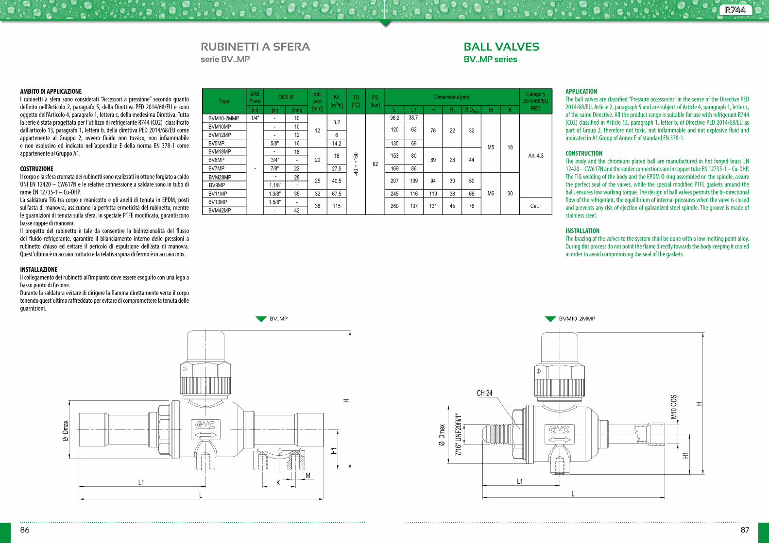
86 87
R744R744
RUBINETTI A SFERA BALL VALVESserie BV..MP BV..MP series
BV..MP BVM10-2MMP
SAE Flare[in] [in] [mm] L L1 H H1 Ø Dmax M K
BVM10-2MMP 1/4" - 10BVM10MP - 10BVM12MP - 12 6BV5MP 5/8" 16 14,2 135 69
BV6MP 3/4" -BVM18MP - 18
BV7MP 7/8" 22 27,5 169 86
BV9MP 1.1/8" -BVM28MP - 28
BV11MP 1.3/8" 35 32 67,5 245 116 119 38 66BV13MP 1.5/8" -BVM42MP - 42
76 22 32
40,5
18
94
115
62120
109207
260 137
TypeODS Ø Ball
port [mm]
Kv [m3/h]
80
TS [°C]
PS [bar]
Dimensions [mm]
153
123,2
-40 ÷
+15
0
62
38
20
25
-
Category 2014/68/EU
PED
Cat. I131 45 76
50
18
89 28 44
30
30
M5
M6
Art. 4.3
96,2 38,7
AMBITO DI APPLICAZIONEI rubinetti a sfera sono considerati “Accessori a pressione” secondo quanto definito nell’Articolo 2, paragrafo 5, della Direttiva PED 2014/68/EU e sono oggetto dell’Articolo 4, paragrafo 1, lettera c, della medesima Direttiva. Tutta la serie è stata progettata per l’utilizzo di refrigerante R744 (CO2) classificato dall’articolo 13, paragrafo 1, lettera b, della direttiva PED 2014/68/EU come appartenente al Gruppo 2, ovvero fluido non tossico, non infiammabile e non esplosivo ed indicato nell’appendice E della norma EN 378-1 come appartenente al Gruppo A1.
COSTRUZIONEIl corpo e la sfera cromata dei rubinetti sono realizzati in ottone forgiato a caldo UNI EN 12420 – CW617N e le relative connessione a saldare sono in tubo di rame EN 12735-1 – Cu-DHP. La saldatura TIG tra corpo e manicotto e gli anelli di tenuta in EPDM, posti sull’asta di manovra, assicurano la perfetta ermeticità del rubinetto, mentre le guarnizioni di tenuta sulla sfera, in speciale PTFE modificato, garantiscono basse coppie di manovra. Il progetto del rubinetto è tale da consentire la bidirezionalità del flusso del fluido refrigerante, garantire il bilanciamento interno delle pressioni a rubinetto chiuso ed evitare il pericolo di espulsione dell’asta di manovra. Quest’ultima è in acciaio trattato e la relativa spina di fermo è in acciaio inox. INSTALLAZIONEIl collegamento dei rubinetti all’impianto deve essere eseguito con una lega a basso punto di fusione.Durante la saldatura evitare di dirigere la fiamma direttamente verso il corpo tenendo quest’ultimo raffreddato per evitare di compromettere la tenuta delle guarnizioni.
APPLICATIONThe ball valves are classified “Pressure accessories” in the sense of the Directive PED 2014/68/EU, Article 2, paragraph 5 and are subject of Article 4, paragraph 1, letter c, of the same Directive. All the product range is suitable for use with refrigerant R744 (CO2) classified in Article 13, paragraph 1, letter b, of Directive PED 2014/68/EU as part of Group 2, therefore not toxic, not inflammable and not explosive fluid and indicated in A1 Group of Annex E of standard EN 378-1. CONSTRUCTIONThe body and the chromium plated ball are manufactured in hot forged brass EN 12420 – CW617N and the solder connections are in copper tube EN 12735-1 – Cu-DHP. The TIG welding of the body and the EPDM O-ring assembled on the spindle, assure the perfect seal of the valves, while the special modified PTFE gaskets around the ball, ensures low working torque. The design of ball valves permits the bi-directional flow of the refrigerant, the equilibrium of internal pressures when the valve is closed and prevents any risk of ejection of galvanized steel spindle. The groove is made of stainless steel.
INSTALLATIONThe brazing of the valves to the system shall be done with a low melting point alloy. During this process do not point the flame directly towards the body keeping it cooled in order to avoid compromising the seal of the gaskets.
L1
L
ØDm
ax
H
MK
H1
L
L1
ØDm
ax
M10
ODS
H1
H
CH 24
7/16
" UNF
20fil/
1"
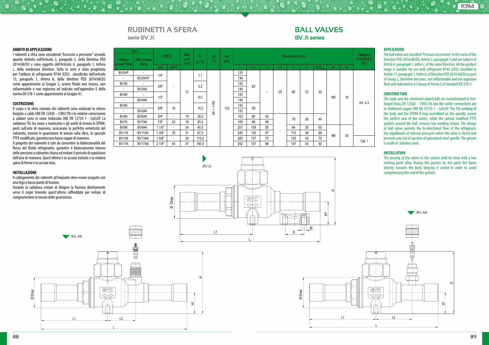
88 89
R744R744
RUBINETTI A SFERA BALL VALVESserie BV..K BV..K series
BV..K
[in] [mm] L L1 L2 L3 H H1 Ø Dmax M KBV2HP - 120
- BV2AHP 136BV3K - 120
- BV3AK 136BV4K - 120
- BV4AK 136BV5K - 135
- BV5AK 152BV6K BV6AK 3/4" - 19 28,0 153 80 45BV7K BV7AK 7/8" 22 18 25,0 169 86 48BV9K BV9AK 1.1/8" - 24 40,5 207 109 55 84 30 50BV11K BV11AK 1.3/8" 35 31 67,0 245 130 67 113 38 66BV13K BV13AK 1.5/8" - 38 115,0 260 137 75 125 45 76BV17K BV17AK 2.1/8" 54 47 180,0 292 157 86 147 55 92
79
165/8"
1/2"
Ball port [mm]
Kv [m3/h]
6612
1,1
6229-
TS [°C]
PS [bar]
Category 2014/68/EU
PED
18
28 44
32
Art. 4.3
M6 30Cat. I
M5
-
-40 ÷
+15
0
120
Without access fitting
With access fitting
ODS Ø Dimensions [mm]Type
22
6914,2
1/4"
-3/8" 3,2
6,0
AMBITO DI APPLICAZIONEI rubinetti a sfera sono considerati “Accessori a pressione” secondo quanto definito nell’Articolo 2, paragrafo 5, della Direttiva PED 2014/68/EU e sono oggetto dell’Articolo 4, paragrafo 1, lettera c, della medesima Direttiva. Tutta la serie è stata progettata per l’utilizzo di refrigerante R744 (CO2) classificato dall’articolo 13, paragrafo 1, lettera b, della direttiva PED 2014/68/EU come appartenente al Gruppo 2, ovvero fluido non tossico, non infiammabile e non esplosivo ed indicato nell’appendice E della norma EN 378-1 come appartenente al Gruppo A1.
COSTRUZIONEIl corpo e la sfera cromata dei rubinetti sono realizzati in ottone forgiato a caldo UNI EN 12420 – CW617N e le relative connessione a saldare sono in rame rinforzato UNI EN 12735-1 - CuFe2P. La saldatura TIG tra corpo e manicotto e gli anelli di tenuta in EPDM, posti sull’asta di manovra, assicurano la perfetta ermeticità del rubinetto, mentre le guarnizioni di tenuta sulla sfera, in speciale PTFE modificato, garantiscono basse coppie di manovra. Il progetto del rubinetto è tale da consentire la bidirezionalità del flusso del fluido refrigerante, garantire il bilanciamento interno delle pressioni a rubinetto chiuso ed evitare il pericolo di espulsione dell’asta di manovra. Quest’ultima è in acciaio trattato e la relativa spina di fermo è in acciaio inox. INSTALLAZIONEIl collegamento dei rubinetti all’impianto deve essere eseguito con una lega a basso punto di fusione.Durante la saldatura evitare di dirigere la fiamma direttamente verso il corpo tenendo quest’ultimo raffreddato per evitare di compromettere la tenuta delle guarnizioni.
APPLICATIONThe ball valves are classified “Pressure accessories” in the sense of the Directive PED 2014/68/EU, Article 2, paragraph 5 and are subject of Article 4, paragraph 1, letter c, of the same Directive. All the product range is suitable for use with refrigerant R744 (CO2) classified in Article 13, paragraph 1, letter b, of Directive PED 2014/68/EU as part of Group 2, therefore not toxic, not inflammable and not explosive fluid and indicated in A1 Group of Annex E of standard EN 378-1. CONSTRUCTIONThe body and the chromium plated ball are manufactured in hot-forged brass EN 12420 – CW617N and the solder connections are in reinforced copper UNI EN 12735-1 - CuFe2P. The TIG welding of the body and the EPDM O-ring assembled on the spindle, assure the perfect seal of the valves, while the special modified PTFE gaskets around the ball, ensures low working torque. The design of ball valves permits the bi-directional flow of the refrigerant, the equilibrium of internal pressures when the valve is closed and prevents any risk of ejection of galvanized steel spindle. The groove is made of stainless steel.
INSTALLATIONThe brazing of the valves to the system shall be done with a low melting point alloy. During this process do not point the flame directly towards the body keeping it cooled in order to avoid compromising the seal of the gaskets.
L1
L
ØDm
ax
H
MK
H1
Ø Dm
ax
L1
L
H
H1
L3 L1
L
L2
H1
Ø Dm
ax
H
BV..AK
BV..AK

90 91
R744R744
RUBINETTI A SFERA BALL VALVESserie BV..HP BV..HP series
BV..HP BVM10 - 2MHP
[in] [in] [mm] L L1 H H1 Ø Dmax M KBVM10-2MHP 1/4" - 10 0,6 96 39BVM10HP - 10 3,2BVM12HP - 12 6,0BV5HP 5/8" 16 14,2 135 69BVM18HP - 18 19 28,0 153 80BV7HP 7/8" 22 18 25,0 147 86BVM28HP - 28 24 40,5 207 109 84 30 50BV11HP 1.3/8" 35 31 67,0 217 116 113 38 66BVM42HP - 42 38 115,0 260 137 125 45 76 Cat. I
30
120
M5
M6
TypeBall port [mm]
Kv [m3/h]
TS [°C]
12
-40 ÷
+15
0
PS [bar]
62
79 28 44
120
Art. 4.3-
Dimensions [mm]SAE Flare ODM Ø
32226618
Category 2014/68/EU
PED
AMBITO DI APPLICAZIONEI rubinetti a sfera sono considerati “Accessori a pressione” secondo quanto definito nell’Articolo 2, paragrafo 5, della Direttiva PED 2014/68/EU e sono oggetto dell’Articolo 4, paragrafo 1, lettera c, della medesima Direttiva. Tutta la serie è stata progettata per l’utilizzo di refrigerante R744 (CO2) classificato dall’articolo 13, paragrafo 1, lettera b, della direttiva PED 2014/68/EU come appartenente al Gruppo 2, ovvero fluido non tossico, non infiammabile e non esplosivo ed indicato nell’appendice E della norma EN 378-1 come appartenente al Gruppo A1.
COSTRUZIONEIl corpo e la sfera cromata dei rubinetti sono realizzati in ottone forgiato a caldo UNI EN 12420 – CW617N e le relative connessione a saldare sono in tubo di acciaio senza saldatura AISI 304. La saldatura TIG tra corpo e manicotto e gli anelli di tenuta in EPDM, posti sull’asta di manovra, assicurano la perfetta ermeticità del rubinetto, mentre le guarnizioni di tenuta sulla sfera, in speciale PTFE modificato, garantiscono basse coppie di manovra. Il progetto del rubinetto è tale da consentire la bidirezionalità del flusso del fluido refrigerante, garantire il bilanciamento interno delle pressioni a rubinetto chiuso ed evitare il pericolo di espulsione dell’asta di manovra. Quest’ultima è in acciaio trattato e la relativa spina di fermo è in acciaio inox.
APPLICATIONThe ball valves are classified “Pressure accessories” in the sense of the Directive PED 2014/68/EU, Article 2, paragraph 5 and are subject of Article 4, paragraph 1, letter c, of the same Directive. All the product range is suitable for use with refrigerant R744 (CO2) classified in Article 13, paragraph 1, letter b, of Directive PED 2014/68/EU as part of Group 2, therefore not toxic, not inflammable and not explosive fluid and indicated in A1 Group of Annex E of standard EN 378-1. CONSTRUCTIONThe body and the chromium plated ball are manufactured in hot-forged brass EN 12420 – CW617N and the solder connections are in seamless steel tube AISI 304. The TIG welding of the body and the EPDM O-ring assembled on the spindle, assure the perfect seal of the valves, while the special modified PTFE gaskets around the ball, ensures low working torque. The design of ball valves permits the bi-directional flow of the refrigerant, the equilibrium of internal pressures when the valve is closed and prevents any risk of ejection of galvanized steel spindle. The groove is made of stainless steel.
L1
L
ØDm
ax
H
MK
H1
L
L1Ø
Dmax
M10
ODM
H1
H
CH 24
7/16
" UNF
20fil/
1"
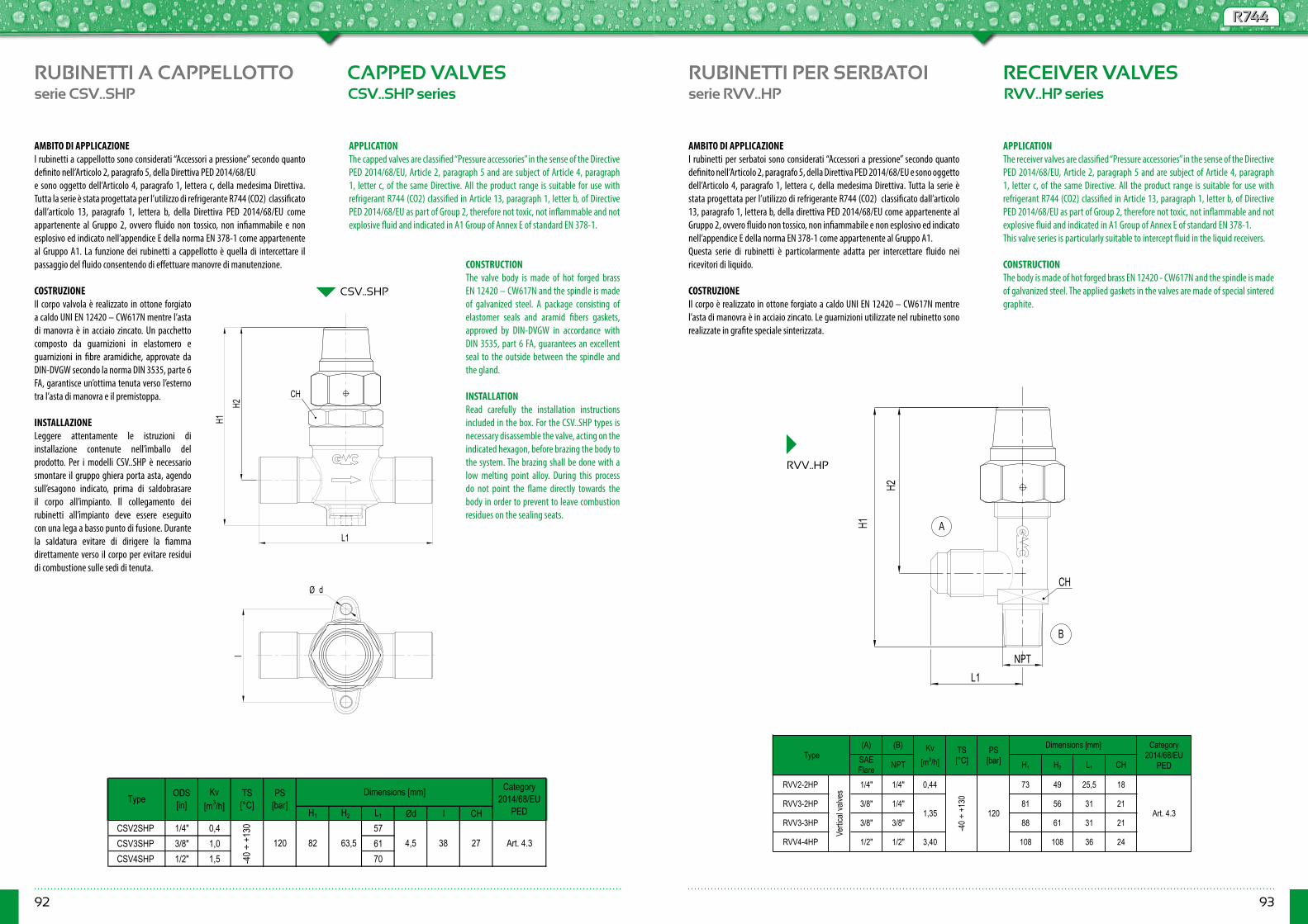
92 93
R744R744
RUBINETTI A CAPPELLOTTO CAPPED VALVESserie CSV..SHP CSV..SHP series
CSV..SHP
H1 H2 L1 Ød I CHCSV2SHP 1/4" 0,4 57CSV3SHP 3/8" 1,0 61CSV4SHP 1/2" 1,5 70
PS [bar]
Dimensions [mm] Category 2014/68/EU
PED
Art. 4.327384,582 63,5
Type
-60 ÷
+11
0
120
Kv [m3/h]
ODS [in]
TS [°C]
AMBITO DI APPLICAZIONEI rubinetti a cappellotto sono considerati “Accessori a pressione” secondo quanto definito nell’Articolo 2, paragrafo 5, della Direttiva PED 2014/68/EU e sono oggetto dell’Articolo 4, paragrafo 1, lettera c, della medesima Direttiva. Tutta la serie è stata progettata per l’utilizzo di refrigerante R744 (CO2) classificato dall’articolo 13, paragrafo 1, lettera b, della Direttiva PED 2014/68/EU come appartenente al Gruppo 2, ovvero fluido non tossico, non infiammabile e non esplosivo ed indicato nell’appendice E della norma EN 378-1 come appartenente al Gruppo A1. La funzione dei rubinetti a cappellotto è quella di intercettare il passaggio del fluido consentendo di effettuare manovre di manutenzione.
COSTRUZIONEIl corpo valvola è realizzato in ottone forgiato a caldo UNI EN 12420 – CW617N mentre l’asta di manovra è in acciaio zincato. Un pacchetto composto da guarnizioni in elastomero e guarnizioni in fibre aramidiche, approvate da DIN-DVGW secondo la norma DIN 3535, parte 6 FA, garantisce un’ottima tenuta verso l’esterno tra l’asta di manovra e il premistoppa. INSTALLAZIONELeggere attentamente le istruzioni di installazione contenute nell’imballo del prodotto. Per i modelli CSV..SHP è necessario smontare il gruppo ghiera porta asta, agendo sull’esagono indicato, prima di saldobrasare il corpo all’impianto. Il collegamento dei rubinetti all’impianto deve essere eseguito con una lega a basso punto di fusione. Durante la saldatura evitare di dirigere la fiamma direttamente verso il corpo per evitare residui di combustione sulle sedi di tenuta.
H1
L1
CH
I
Ø d
H2
APPLICATIONThe capped valves are classified “Pressure accessories” in the sense of the Directive PED 2014/68/EU, Article 2, paragraph 5 and are subject of Article 4, paragraph 1, letter c, of the same Directive. All the product range is suitable for use with refrigerant R744 (CO2) classified in Article 13, paragraph 1, letter b, of Directive PED 2014/68/EU as part of Group 2, therefore not toxic, not inflammable and not explosive fluid and indicated in A1 Group of Annex E of standard EN 378-1.
CONSTRUCTIONThe valve body is made of hot forged brass EN 12420 – CW617N and the spindle is made of galvanized steel. A package consisting of elastomer seals and aramid fibers gaskets, approved by DIN-DVGW in accordance with DIN 3535, part 6 FA, guarantees an excellent seal to the outside between the spindle and the gland.
INSTALLATIONRead carefully the installation instructions included in the box. For the CSV..SHP types is necessary disassemble the valve, acting on the indicated hexagon, before brazing the body to the system. The brazing shall be done with a low melting point alloy. During this process do not point the flame directly towards the body in order to prevent to leave combustion residues on the sealing seats.
RUBINETTI PER SERBATOI RECEIVER VALVESserie RVV..HP RVV..HP series
RVV..HP
(A) (B)SAE Flare NPT H1 H2 L1 CH
RVV2-2HP 1/4" 1/4" 0,44 73 49 25,5 18
RVV3-2HP 3/8" 1/4" 81 56 31 21
RVV3-3HP 3/8" 3/8" 88 61 31 21
RVV4-4HP 1/2" 1/2" 3,40 108 108 36 24
Type
1,35 Art. 4.3
PS [bar]
Kv [m3/h]
Vertic
al va
lves
-40 ÷
+13
0
120
Dimensions [mm]TS [°C]
Category 2014/68/EU
PED
AMBITO DI APPLICAZIONEI rubinetti per serbatoi sono considerati “Accessori a pressione” secondo quanto definito nell’Articolo 2, paragrafo 5, della Direttiva PED 2014/68/EU e sono oggetto dell’Articolo 4, paragrafo 1, lettera c, della medesima Direttiva. Tutta la serie è stata progettata per l’utilizzo di refrigerante R744 (CO2) classificato dall’articolo 13, paragrafo 1, lettera b, della direttiva PED 2014/68/EU come appartenente al Gruppo 2, ovvero fluido non tossico, non infiammabile e non esplosivo ed indicato nell’appendice E della norma EN 378-1 come appartenente al Gruppo A1.Questa serie di rubinetti è particolarmente adatta per intercettare fluido nei ricevitori di liquido.
COSTRUZIONEIl corpo è realizzato in ottone forgiato a caldo UNI EN 12420 – CW617N mentre l’asta di manovra è in acciaio zincato. Le guarnizioni utilizzate nel rubinetto sono realizzate in grafite speciale sinterizzata.
APPLICATIONThe receiver valves are classified “Pressure accessories” in the sense of the Directive PED 2014/68/EU, Article 2, paragraph 5 and are subject of Article 4, paragraph 1, letter c, of the same Directive. All the product range is suitable for use with refrigerant R744 (CO2) classified in Article 13, paragraph 1, letter b, of Directive PED 2014/68/EU as part of Group 2, therefore not toxic, not inflammable and not explosive fluid and indicated in A1 Group of Annex E of standard EN 378-1.This valve series is particularly suitable to intercept fluid in the liquid receivers. CONSTRUCTIONThe body is made of hot forged brass EN 12420 - CW617N and the spindle is made of galvanized steel. The applied gaskets in the valves are made of special sintered graphite.
L1
CH
H1
H2
B
A
NPT
-40 ÷
+13
0

94
R744R744
95
RUBINETTI PER GRUPPI ERMETICI
VALVES FOR HERMETICSYSTEMS
serie VHU..HP VHU..HP series
(B)
ODS Ø SAE Flare
SAE Flare H H1 L1 L2 Ød I
VHU2-2HP - 1/4" 1/4" 0,27 28
VHU2-2SHP 1/4" - 1/4" 0,45 26
Category 2014/68/EU
PED
-40 ÷
+13
0
120 59,5 13 28 4,5 38 Art. 4.3
Dimensions [mm]Type
(A)Kv
[m3/h]TS [°C]
PS [bar]
AMBITO DI APPLICAZIONEI rubinetti per gruppi ermetici sono considerati “Accessori a pressione” secondo quanto definito nell’Articolo 2, paragrafo 5, della Direttiva PED 2014/68/EU e sono oggetto dell’Articolo 4, paragrafo 1, lettera c, della medesima Direttiva. Tutta la serie è stata progettata per l’utilizzo di refrigerante R744 (CO2) classificato dall’articolo 13, paragrafo 1, lettera b, della Direttiva PED 2014/68/EU come appartenente al Gruppo 2, ovvero fluido non tossico, non infiammabile e non esplosivo ed indicato nell’appendice E della norma EN 378-1 come appartenente al Gruppo A1. Questa serie di rubinetti è particolarmente adatta per sistemi che utilizzano compressori ermetici.
COSTRUZIONEIl corpo valvola è realizzato in ottone forgiato a caldo UNI EN 12420 – CW617N mentre l’asta di manovra è in acciaio zincato. Un pacchetto composto da guarnizioni in elastomero e guarnizioni in fibre aramidiche, approvate da DIN-DVGW secondo la norma DIN 3535, parte 6 FA, garantisce un’ottima tenuta verso l’esterno tra l’asta di manovra e il premistoppa. INSTALLAZIONEPer il modello a saldare, il collegamento all’impianto deve essere eseguito con una lega a basso punto di fusione. Durante la saldatura evitare di dirigere la fiamma direttamente verso il corpo preservando così l’integrità delle guarnizioni.
PRODOTTI IDONEI PER REFRIGERANTI IDROCARBURII prodotti per refrigeranti idrocarburi presentati in questo catalogo possono essere impiegati con i seguenti fluidi frigoriferi: R290 (propano), R600 (butano) e R600a (isobutano).Questi refrigeranti sono classificati come fluidi infiammabili appartenenti al Gruppo di sicurezza A3 secondo la norma EN 378-1: 2008 + A1.I suddetti prodotti devono essere utilizzati esclusivamente su sistemi frigoriferi che siano conformi alle normative vigenti in materia di fluidi refrigeranti infiammabili (serie EN 60335).Interventi d’installazione, manutenzione e riparazione devono essere condotti solamente da personale autorizzato, qualificato a operare su impianti con refrigeranti infiammabili.Per applicazioni specifiche con fluidi refrigeranti non elencati sopra, prego contattare l’Ufficio Tecnico di GMC Refrigerazione.
APPLICATIONThe valves for hermetic system are classified “Pressure accessories” in the sense of the Directive PED 2014/68/EU, Article 2, paragraph 5 and are subject of Article 4, paragraph 1, letter c, of the same Directive. All the product range is suitable for use with refrigerant R744 (CO2) classified in Article 13, paragraph 1, letter b, of Directive PED 2014/68/EU as part of Group 2, therefore not toxic, not inflammable and not explosive fluid and indicated in A1 Group of Annex E of standard EN 378-1. This valve series is particularly suitable for systems using hermetic compressors. CONSTRUCTIONThe valve body is made of hot forged brass EN 12420 – CW617N and the spindle is made of galvanized steel. A package consisting of elastomer seals and aramid fibers gaskets, approved by DIN-DVGW in accordance with DIN 3535, part 6 FA, guarantees an excellent seal to the outside between the spindle and the gland.
INSTALLATIONFor soldering type the brazing to the system shall be done with a low melting point alloy. During this process do not point the flame directly towards the body in order to save the gaskets.
PRODUCTS SUITABLE FOR HYDROCARBONS REFRIGERANTSThe products for hydrocarbons refrigerants shown in this catalogue can be used with the following refrigerant fluids: R290 (propane), R600 (butane) and R600a (isobutane).These refrigerants are classified as flammable fluids proper to Safety Group A3 according to EN 378-1: 2008 + A1 Standard.The aforesaid products must be used solely on refrigerating systems that are in compliance with regulations about flammable refrigerant fluids (series EN 60335).Only authorized persons, qualified to work on refrigerating systems containing flammable hydrocarbons, may do installation, maintenance and repair.For specific applications with refrigerant fluids not listed above, please contact GMC Refrigerazione Technical Department.
Ø d
I
L1
HH1
AB B A
L2 L1
H1
L2
H
VHU2-2HP
VHU2-2SHP
-40 ÷
+13
0
96 97
HCHC
PRODOTTI PER REFRIGERANTI IDROCARBURI
PRODUCTS FORHYDROCARBON REFRIGERANTS
INFORMAZIONI GENERALI
La maggior parte dei fluidi refrigeranti oggi in uso sono sostanze ottenute per sintesi chimica e quindi con caratteristiche ideali per questo scopo. Molte di queste però hanno effetti negativi sull’ambiente, in particolare hanno un elevato potenziale di distruzione dell’ozono atmosferico (ODP, Ozone Depletion Potential) o contribuiscono direttamente all’effetto serra (hanno elevato GWP, Global Warming Potential).Per questo motivo molti paesi hanno già provveduto ad impedire o limitare l’uso dei refrigeranti sintetici di tipo CFC ed HCFC e stanno decidendo le sorti degli HFC a favore di refrigeranti con bassi o nulli ODP e GWP.Tra questi ultimi troviamo gli idrocarburi tra cui R290 (Propano), R600 (Butano) e R600a (Isobutano) che pur essendo meno efficienti dei refrigeranti sintetici sono fluidi naturali con ODP=0 e GWP trascurabile.I refrigeranti idrocarburi sono classificati dall’articolo 13, paragrafo 1, lettera a, della direttiva PED 2014/68/EU come appartenenti al Gruppo 1 ed indicati nell’appendice E della norma EN 378-1 come appartenenti al Gruppo A3.A causa del loro elevato grado di infiammabilità l’utilizzo di queste sostanze implica particolari accortezze in fase di progettazione. Gli idrocarburi infatti presentano rischio di esplosione se la loro concentrazione è compresa tra il limite di infiammabilità inferiore e superiore.Le pressioni di esercizio simili e la compatibilità con oli e con materiali standard utilizzati dai classici refrigeranti sintetici rendono gli idrocarburi perfetti sostituti in applicazioni commerciali domestiche leggere.
La gamma di prodotti per refrigeranti idrocarburi di GMC REFRIGERAZIONE è stata studiata appositamente per tali applicazioni. La tenuta viene garantita da prove con macchine ad Elio per la rilevazione di micro perdite effettuate secondo la tecnica B6 dell’appendice A (caratteristiche specifiche dei metodi di ricerca delle perdite) della Norma UNI EN 1779:2004.
GENERAL INFORMATION
The majority of refrigerants in use today are substances obtained by chemical synthesis, with high refrigeration performance. Unfortunately big part of them have negative environmental effects, with a high potential for atmospheric ozone destruction (ODP, Ozone Depletion Potential) or directly contribute to the greenhouse effect (have high GWP, Global Warming Potential).That’s why many countries have already taken steps to prevent or limit the use of synthetic type CFC and HCFC refrigerants and are deciding about HFC in favor of refrigerants with low or zero ODP and GWP.Among the latter there are hydrocarbons such as R290 (propane), R600 (butane) and R600a (isobutane) which despite being less efficient than synthetic refrigerants are natural fluids with ODP=0 and GWP negligible.The hydrocarbon refrigerants are classified by Article 13, paragraph 1, letter a, of the PED Directive 2014/68/EU as belonging to Group 1 and in Appendix E of EN 378-1 as belonging to A3 Group.Because of their high degree of flammability, the use of these substances require some particular precautions in the design step. The hydrocarbons present in fact a risk of explosion if their concentration is between the lower and upper flammable limit.The similar operating pressures and compatibility with oils and standard materials used at classical synthetic refrigeration circuits, make hydrocarbons a perfect substitute in domestic and small commercial applications.
All GMC REFRIGERAZIONE products for Hydrocarbon refrigerants have been specially designed for such applications. The seal is guaranteed by helium tests for the detection of micro leakages according to Method B.6 of Appendix A (specific properties of leakage searching methods) of standard UNI EN 1779:2004.
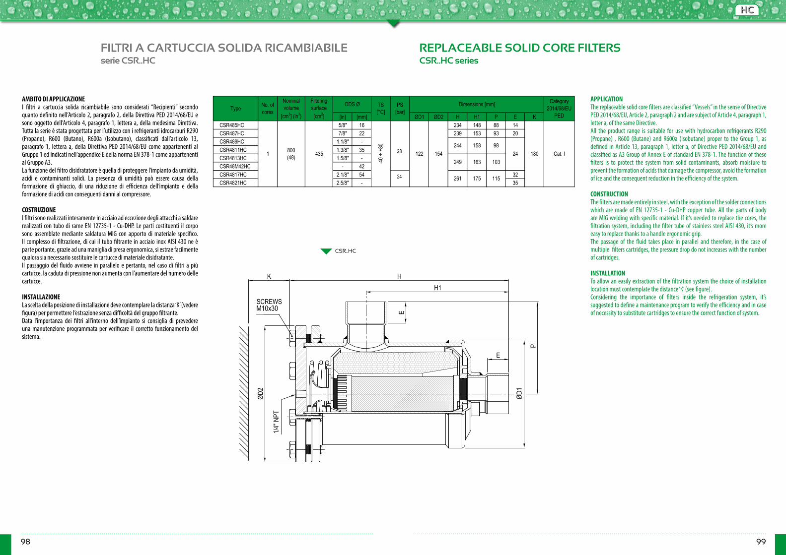
98 99
HCHC
FILTRI A CARTUCCIA SOLIDA RICAMBIABILE REPLACEABLE SOLID CORE FILTERSserie CSR..HC CSR..HC series
[in] [mm] ØD1 ØD2 H H1 P E KCSR485HC 5/8" 16 234 148 88 14CSR487HC 7/8" 22 239 153 93 20CSR489HC 1.1/8" -CSR4811HC 1.3/8" 35CSR4813HC 1.5/8" -CSR48M42HC - 42CSR4817HC 2.1/8" 54 32CSR4821HC 2.5/8" - 35
Category 2014/68/EU
PED
175
981 800
(48) 435
-40 ÷
+80
24 122 154 180 Cat. I244 158
261 115
Type No. of cores
Nominal volume
[cm3] (in3)
Filtering surface [cm2]
ODS Ø TS [°C]
PS [bar]
Dimensions [mm]
24249 163 103
AMBITO DI APPLICAZIONEI filtri a cartuccia solida ricambiabile sono considerati “Recipienti” secondo quanto definito nell’Articolo 2, paragrafo 2, della Direttiva PED 2014/68/EU e sono oggetto dell’Articolo 4, paragrafo 1, lettera a, della medesima Direttiva. Tutta la serie è stata progettata per l’utilizzo con i refrigeranti idrocarburi R290 (Propano), R600 (Butano), R600a (Isobutano), classificati dall’articolo 13, paragrafo 1, lettera a, della Direttiva PED 2014/68/EU come appartenenti al Gruppo 1 ed indicati nell’appendice E della norma EN 378-1 come appartenenti al Gruppo A3.La funzione del filtro disidratatore è quella di proteggere l’impianto da umidità, acidi e contaminanti solidi. La presenza di umidità può essere causa della formazione di ghiaccio, di una riduzione di efficienza dell’impianto e della formazione di acidi con conseguenti danni al compressore.
COSTRUZIONEI filtri sono realizzati interamente in acciaio ad eccezione degli attacchi a saldare realizzati con tubo di rame EN 12735-1 - Cu-DHP. Le parti costituenti il corpo sono assemblate mediante saldatura MIG con apporto di materiale specifico. Il complesso di filtrazione, di cui il tubo filtrante in acciaio inox AISI 430 ne è parte portante, grazie ad una maniglia di presa ergonomica, si estrae facilmente qualora sia necessario sostituire le cartucce di materiale disidratante. Il passaggio del fluido avviene in parallelo e pertanto, nel caso di filtri a più cartucce, la caduta di pressione non aumenta con l’aumentare del numero delle cartucce.
INSTALLAZIONELa scelta della posizione di installazione deve contemplare la distanza ‘K’ (vedere figura) per permettere l’estrazione senza difficoltà del gruppo filtrante.Data l’importanza dei filtri all’interno dell’impianto si consiglia di prevedere una manutenzione programmata per verificare il corretto funzionamento del sistema.
APPLICATIONThe replaceable solid core filters are classified “Vessels” in the sense of Directive PED 2014/68/EU, Article 2, paragraph 2 and are subject of Article 4, paragraph 1, letter a, of the same Directive.All the product range is suitable for use with hydrocarbon refrigerants R290 (Propane) , R600 (Butane) and R600a (Isobutane) proper to the Group 1, as defined in Article 13, paragraph 1, letter a, of Directive PED 2014/68/EU and classified as A3 Group of Annex E of standard EN 378-1. The function of these filters is to protect the system from solid contaminants, absorb moisture to prevent the formation of acids that damage the compressor, avoid the formation of ice and the consequent reduction in the efficiency of the system.
CONSTRUCTIONThe filters are made entirely in steel, with the exception of the solder connections which are made of EN 12735-1 - Cu-DHP copper tube. All the parts of body are MIG welding with specific material. If it’s needed to replace the cores, the filtration system, including the filter tube of stainless steel AISI 430, it’s more easy to replace thanks to a handle ergonomic grip.The passage of the fluid takes place in parallel and therefore, in the case of multiple filters cartridges, the pressure drop do not increases with the number of cartridges.
INSTALLATIONTo allow an easily extraction of the filtration system the choice of installation location must contemplate the distance ‘K’ (see figure).Considering the importance of filters inside the refrigeration system, it’s suggested to define a maintenance program to verify the efficiency and in case of necessity to substitute cartridges to ensure the correct function of system.
H1
E
P
E
H
ØD2
K
ØD1
SCREWSM10x30
1/4" N
PT
CSR..HC
28
24
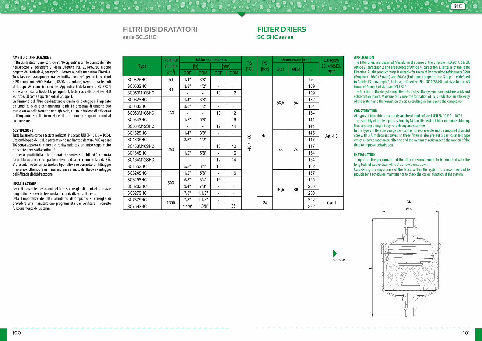
100 101
HCHC
FILTRI DISIDRATATORI FILTER DRIERSserie SC..SHC SC..SHC series
SC..SHC
ODF ODM ODF ODMSC032SHC 50 1/4" 3/8" - - 95SC053SHC 3/8" 1/2" - - 109SC053M10SHC - - 10 12 109SC082SHC 1/4" 3/8" - - 132SC083SHC 3/8" 1/2" - - 134SC083M10SHC - - 10 12 134SC084SHC 1/2" 5/8" - 16 141SC084M12SHC - - 12 14 141SC162SHC 1/4" 3/8" - - 145SC163SHC 3/8" 1/2" - - 147SC163M10SHC - - 10 12 147SC164SHC 1/2" 5/8" - 16 154SC164M12SHC - - 12 14 154SC165SHC 5/8" 3/4" 16 - 162SC324SHC 1/2" 5/8" - 16 187SC325SHC 5/8" 3/4" 16 - 195SC326SHC 3/4" 7/8" - - 200SC327SHC 7/8" 1.1/8" - - 200SC757SHC 7/8" 1.1/8" - - 392SC759SHC 1.1/8" - - - 392
TypeNominal volume [cm3]
Solder connectionsTS [°C]
PS [bar]
Dimensions [mm] Category 2014/68/EU
PED [in] [mm]
ØD1 ØD2 L
74
50094,5 89
1300 24
80
130
Cat. I
-40 ÷
+80 35
58,5 54
Art. 4.3
250 78
AMBITO DI APPLICAZIONEI filtri disidratatori sono considerati “Recipienti” secondo quanto definito nell’Articolo 2, paragrafo 2, della Direttiva PED 2014/68/EU e sono oggetto dell’Articolo 4, paragrafo 1, lettera a, della medesima Direttiva. Tutta la serie è stata progettata per l’utilizzo con i refrigeranti idrocarburi R290 (Propano), R600 (Butano), R600a (Isobutano) ovvero appartenenti al Gruppo A3 come indicato nell’Appendice E della norma EN 378-1 e classificati dall’articolo 13, paragrafo 1, lettera a, della Direttiva PED 2014/68/EU come appartenenti al Gruppo 1.La funzione del filtro disidratatore è quella di proteggere l’impianto da umidità, acidi e contaminanti solidi. La presenza di umidità può essere causa della formazione di ghiaccio, di una riduzione di efficienza dell’impianto e della formazione di acidi con conseguenti danni al compressore.
COSTRUZIONETutta la serie ha corpo e testata realizzati in acciaio UNI EN 10130 – DC04.L’assemblaggio delle due parti avviene mediante saldatura MIG oppure TIG senza apporto di materiale, realizzando così un unico corpo molto resistente e senza discontinuità.In questo tipo di filtri la carica disidratante non è sostituibile ed è composta da un blocco unico e compatto di sferette di setaccio molecolare da 3 Å. E’ presente inoltre un particolare tipo feltro che permette un filtraggio meccanico, offrendo la minima resistenza al moto del fluido a vantaggio dell’efficacia di disidratazione. INSTALLAZIONEPer ottimizzare le prestazioni del filtro si consiglia di montarlo con asse longitudinale in verticale e con la freccia rivolta verso il basso.Data l’importanza dei filtri all’interno dell’impianto si consiglia di prevedere una manutenzione programmata per verificare il corretto funzionamento del sistema.
APPLICATIONThe Filter driers are classified “Vessels” in the sense of the Directive PED 2014/68/EU, Article 2, paragraph 2 and are subject of Article 4, paragraph 1, letter a, of the same Directive. All the product range is suitable for use with hydrocarbon refrigerants R290 (Propane) , R600 (Butane) and R600a (Isobutane) proper to the Group 1, as defined in Article 13, paragraph 1, letter a, of Directive PED 2014/68/EU and classified as A3 Group of Annex E of standard EN 378-1.The function of the dehydrating filter is to protect the system from moisture, acids and solid contaminants. Moisture can cause the formation of ice, a reduction in efficiency of the system and the formation of acids, resulting in damage to the compressor. CONSTRUCTIONAll types of filter driers have body and head made of steel UNI EN 10130 – DC04.The assembly of the two parts is done by MIG or TIG without filler material soldering, thus creating a single body very strong and seamless.In this type of filters the charge desiccant is not replaceable and is composed of a solid core with 3 Å moleculars sieves. In these filters is also present a particular felt type which allows a mechanical filtering and the minimum resistance to the motion of the fluid to improve dehydration.
INSTALLATIONTo optimize the performance of the filter is recommended to be mounted with the longitudinal axis vertical while the arrow points down.Considering the importance of the filters within the system it is recommended to provide for a scheduled maintenance to check the correct function of the system.
L
ØD1
ØD21.3/8” 35
45
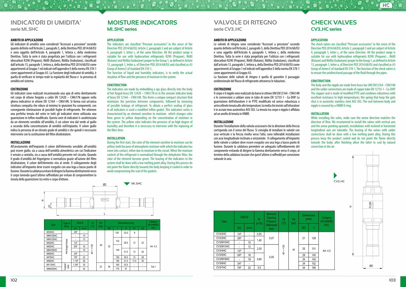
102 103
HCHC
INDICATORI DI UMIDITA’ MOISTURE INDICATORSserie MI..SHC serie CV3..HCMI..SHC series CV3..HC series
[in] [mm] ØD L H H1 CHMI3SHC 3/8" -MIM10SHC - 10MIM12SHC - 12MI4SHC 1/2" -MI5SHC 5/8" 16MIM18SHC - 18MI6SHC 3/4" -MI7SHC 7/8" 22 155 35,5 15 28MI9SHC 1.1/8" 28 183 41,5 17,5 35MI11SHC 1.3/8" 35 160 33,5 - -MIM42SHC - 42 170 37 - -
Category 2014/68/EU
PED
24
Copp
er
tube 36
35 Art. 4.3
Cat. I
Type PS [bar]
Dimensions [mm]
22
Hot fo
rged
bras
s
-20 ÷
+10
5 32
22
Type of Body
13
132
ODS Ø TS [°C]
12
14531,5
29,5
[in] [mm] ØD H
CV3/2HC 1/4" - 0,55CV3/3HC 3/8" -CV3/M10HC - 10CV3/M12HC - 12CV3/4HC 1/2" -CV3/5HC 5/8" 16 29 145CV3/M18HC - 18 34 145CV3/6HC 3/4" - 34 152CV3/7HC 7/8" 22 5,5 34 166
Dimensions [mm] Category
2014/68/EU PED
TS [°C]
2,00
0,05
25 131
3,60
0,07
-20 ÷
+10
5
35
21 128
Art. 4.3
1,40
TypeKv
[m3/h]
Minimum OpeningPressure
Differential[bar]
PS [bar]
ODS Ø
AMBITO DI APPLICAZIONEGli indicatori di umidità sono considerati “Accessori a pressione” secondo quanto definito nell’Articolo 2, paragrafo 5, della Direttiva PED 2014/68/EU e sono oggetto dell’Articolo 4, paragrafo 1, lettera c, della medesima Direttiva. Tutta la serie è stata progettata per l’utilizzo con i refrigeranti idrocarburi R290 (Propano), R600 (Butano), R600a (Isobutano), classificati dall’articolo 13, paragrafo 1, lettera a, della direttiva PED 2014/68/EU come appartenenti al Gruppo 1 ed indicati nell’appendice E della norma EN 378-1 come appartenenti al Gruppo A3. La Funzione degli indicatori di umidità, è quella di verificare in tempo reale la regolarità del flusso e la presenza di umidità nel sistema.
COSTRUZIONEGli indicatori sono realizzati incastonando una spia di vetro direttamente nel corpo di ottone forgiato a caldo EN 12420 – CW617N oppure nella ghiera indicatrice in ottone EN 12164 – CW614N. Si forma così un’unica struttura compatta che riduce al minimo le giunzioni fra componenti, con conseguente eliminazione di possibili fughe di refrigerante. Per ottenere una perfetta tenuta del vetro in tutti gli indicatori viene utilizzata una guarnizione in teflon modificato. Questa serie di indicatori è caratterizzata da un elemento sensibile all’umidità, il cui colore vira dal verde al giallo a seconda della concentrazione di umidità nell’impianto. Il colore giallo indica la presenza di un elevato grado di umidità e che quindi è necessario intervenire con la sostituzione del filtro disidratatore. INSTALLAZIONEAll’avviamento dell’impianto il colore dell’elemento sensibile all’umidità può essere giallo, sia a causa dell’umidità atmosferica con cui l’indicatore è venuto a contatto, sia a causa dell’umidità presente nel circuito. Quando il grado d’umidità del frigorigeno si normalizza grazie all’azione del filtro disidratatore, il colore dell’elemento vira al verde. Il collegamento degli indicatori all’impianto deve essere eseguito con una lega a basso punto di fusione. Durante la saldatura evitare di dirigere la fiamma direttamente verso il corpo tenendo quest’ultimo raffreddato per evitare di compromettere la tenuta della guarnizione tra vetro e corpo d’ottone.
APPLICATIONThe indicators are classified “Pressure accessories” in the sense of the Directive PED 2014/68/EU, Article 2, paragraph 5 and are subject of Article 4, paragraph 1, letter c, of the same Directive. All the product range is suitable for use with hydrocarbon refrigerants R290 (Propane), R600 (Butane) and R600a (Isobutane) proper to the Group 1, as defined in Article 13, paragraph 1, letter a, of Directive PED 2014/68/EU and classified as A3 Group of Annex E of standard EN 378-1. The function of liquid and humidity indicators, is to verify the actual situation of flow and the presence of moisture in the system. CONSTRUCTIONThe indicators are made by embedding a spy glass directly into the body of hot forged brass EN 12420 – CW617N or in the annular indicator body of brass EN 12164 – CW614N. This forms a unique compact structure that minimizes the junctions between components, followed by removing of possible leakage of refrigerant. To obtain a perfect sealing of glass in all indicators is used a modified teflon gasket. This indicators series is characterized by an element sensitive to moisture which changes color from green to yellow depending on the concentration of moisture in the system. The yellow color indicates the presence of an high degree of humidity and therefore it is necessary to intervene with the replacing of the filter drier.
INSTALLATIONDuring the first start, the color of the element sensitive to moisture can be yellow, both because of atmospheric moisture with which the indicator has come into contact, either due to moisture in the circuit. When the moisture content of the refrigerant is normalized through the dehydrator filter, the color of the element become green. The brazing of the indicators to the system shall be done with a low melting point alloy. During this process do not point the flame directly towards the body keeping it cooled in order to avoid compromising the seal of the gaskets.
VALVOLE DI RITEGNO CHECK VALVES
AMBITO DI APPLICAZIONELe valvole di ritegno sono considerate “Accessori a pressione” secondo quanto definito nell’Articolo 2, paragrafo 5, della Direttiva PED 2014/68/EU e sono oggetto dell’Articolo 4, paragrafo 1, lettera c, della medesima Direttiva. Tutta la serie è stata progettata per l’utilizzo con i refrigeranti idrocarburi R290 (Propano), R600 (Butano), R600a (Isobutano), classificati dall’articolo 13, paragrafo 1, lettera a, della Direttiva PED 2014/68/EU come appartenenti al Gruppo 1 ed indicati nell’appendice E della norma EN 378-1 come appartenenti al Gruppo A3.La funzione delle valvole di ritegno è quella di garantire il passaggio unidirezionale del flusso di refrigerante attraverso le tubazioni.
COSTRUZIONEIl corpo e il nipplo sono realizzati da barra in ottone UNI EN12164 - CW614N e le connessioni a saldare sono in tubo di rame EN 12735-1 - Cu-DHP. La guarnizione dell’otturatore è in PTFE modificato ed unisce robustezza a un’eccellente tenuta alle alte temperature; la molla che insiste sull’otturatore è in acciaio inox austenitico AISI 302. La tenuta tra corpo e nipplo è affidata ad un anello di tenuta in HNBR.
INSTALLAZIONEDurante l’installazione della valvola assicurarsi che la direzione della freccia corrisponda con il senso del flusso. Si consiglia di installare le valvole con asse verticale e la freccia rivolta verso l’alto; sono tollerabili installazioni con asse longitudinale inclinato o orizzontale. Il collegamento all’impianto delle valvole a saldare deve essere eseguito con una lega a basso punto di fusione. Durante la saldatura prevedere un adeguato raffreddamento del componente evitando di dirigere la fiamma direttamente verso il corpo; al termine della saldatura lasciare che quest’ultimo si raffreddi per convezione naturale in aria.
APPLICATIONThe check valves are classified “Pressure accessories” in the sense of the Directive PED 2014/68/EU, Article 2, paragraph 5 and are subject of Article 4, paragraph 1, letter c, of the same Directive. All the product range is suitable for use with hydrocarbon refrigerants R290 (Propane) , R600 (Butane) and R600a (Isobutane) proper to the Group 1, as defined in Article 13, paragraph 1, letter a, of Directive PED 2014/68/EU and classified as A3 Group of Annex E of standard EN 378-1. The function of the check valves is to ensure the unidirectional passage of the fluid through the pipes. CONSTRUCTIONThe body and the nipple are made from brass bar UNI EN12164 - CW614N and the solder connections are made of copper tube EN 12735-1 - Cu-DHP. The clapper seat is made of modified PTFE and combines robustness with excellent resistance to high temperatures; the spring that keep the gate shut is in austenitic stainless steel AISI 302. The seal between body and nipple is ensured by a HNBR O-ring.
INSTALLATIONWhile installing the valve, make sure the arrow direction matches the direction of flow. We recommend to install the valves with vertical axis and the arrow pointing upwards; installations with inclined or horizontal longitudinal axis are tolerable. The brazing of the valves with solder connections shall be done with a low melting point alloy. During this process keep the product cooled and do not point the flame directly towards the body; after finishing allow the latter to cool by natural convection in the air.
ØD
H1
H
L
ØD
H FLO
W
CV3..HCMI..SHC
125 22,5 8
45
-40 ÷
+12
0
-40 ÷
+13
0
45
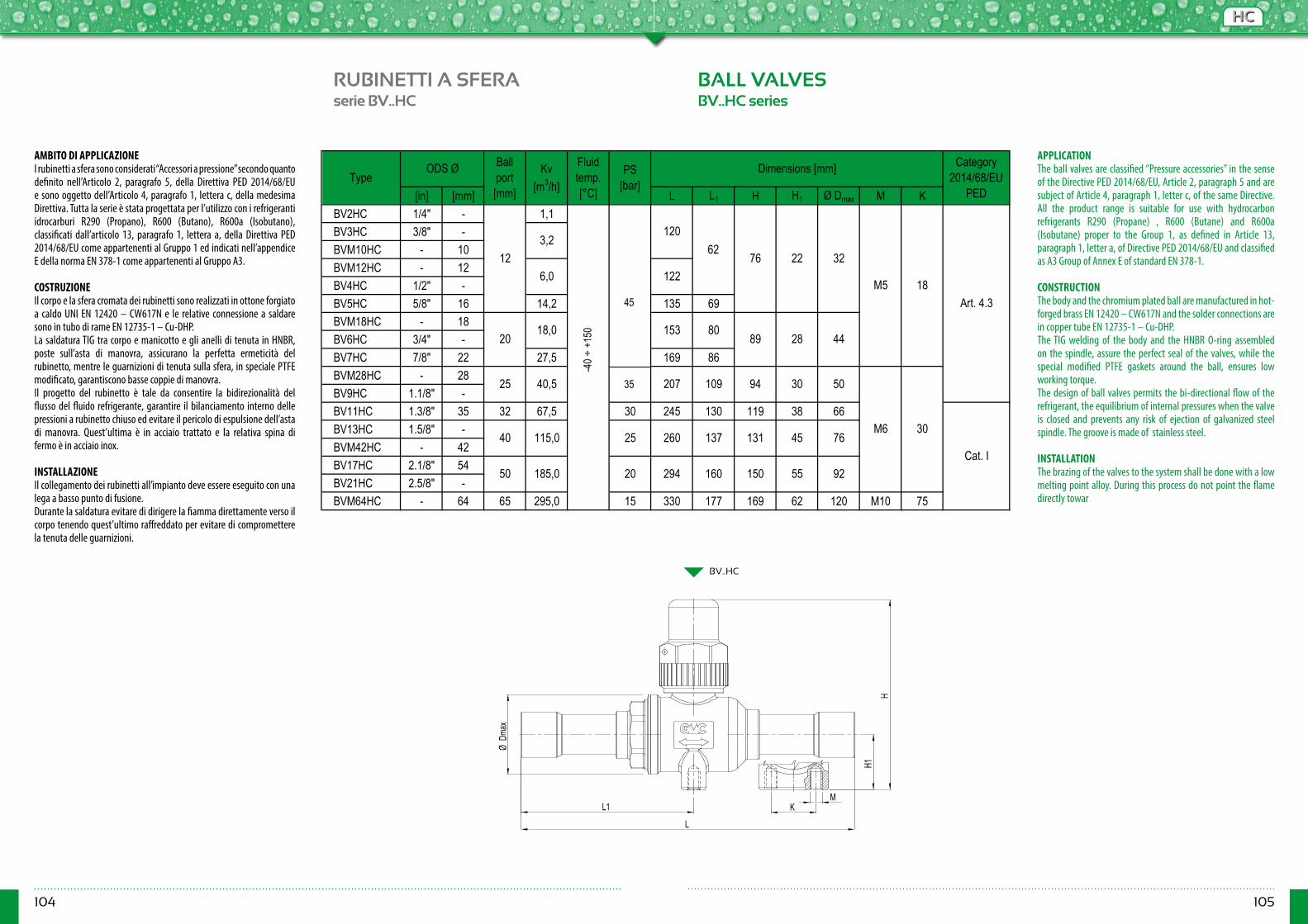
104 105
HCHC
RUBINETTI A SFERA BALL VALVESserie BV..HC BV..HC series
BV..HC
[in] [mm] L L1 H H1 Ø Dmax M KBV2HC 1/4" - 1,1BV3HC 3/8" -BVM10HC - 10BVM12HC - 12BV4HC 1/2" -BV5HC 5/8" 16 14,2 135 69BVM18HC - 18BV6HC 3/4" -BV7HC 7/8" 22 27,5 169 86BVM28HC - 28BV9HC 1.1/8" -BV11HC 1.3/8" 35 32 67,5 30 245 130 119 38 66BV13HC 1.5/8" -BVM42HC - 42BV17HC 2.1/8" 54BV21HC 2.5/8" -BVM64HC - 64 65 295,0 15 330 177 169 62 120 M10 75
30 50
131 45
20 294 160 150
94
TypeDimensions [mm]
18
76 22 32
89 28 44
Ball port [mm]
M5
ODS Ø
18,0
Kv [m3/h]
Category 2014/68/EU
PED
6,0
3,2
153 80
Fluid temp. [°C]
PS [bar]
62
Art. 4.3
-20 ÷
+15
0
120
55 92
M6 30
185,050
12
20
25
Cat. I25 260 137
40,5
115,0
35
207
76
122
109
40
AMBITO DI APPLICAZIONEI rubinetti a sfera sono considerati “Accessori a pressione” secondo quanto definito nell’Articolo 2, paragrafo 5, della Direttiva PED 2014/68/EU e sono oggetto dell’Articolo 4, paragrafo 1, lettera c, della medesima Direttiva. Tutta la serie è stata progettata per l’utilizzo con i refrigeranti idrocarburi R290 (Propano), R600 (Butano), R600a (Isobutano), classificati dall’articolo 13, paragrafo 1, lettera a, della Direttiva PED 2014/68/EU come appartenenti al Gruppo 1 ed indicati nell’appendice E della norma EN 378-1 come appartenenti al Gruppo A3.
COSTRUZIONEIl corpo e la sfera cromata dei rubinetti sono realizzati in ottone forgiato a caldo UNI EN 12420 – CW617N e le relative connessione a saldare sono in tubo di rame EN 12735-1 – Cu-DHP. La saldatura TIG tra corpo e manicotto e gli anelli di tenuta in HNBR, poste sull’asta di manovra, assicurano la perfetta ermeticità del rubinetto, mentre le guarnizioni di tenuta sulla sfera, in speciale PTFE modificato, garantiscono basse coppie di manovra. Il progetto del rubinetto è tale da consentire la bidirezionalità del flusso del fluido refrigerante, garantire il bilanciamento interno delle pressioni a rubinetto chiuso ed evitare il pericolo di espulsione dell’asta di manovra. Quest’ultima è in acciaio trattato e la relativa spina di fermo è in acciaio inox. INSTALLAZIONEIl collegamento dei rubinetti all’impianto deve essere eseguito con una lega a basso punto di fusione.Durante la saldatura evitare di dirigere la fiamma direttamente verso il corpo tenendo quest’ultimo raffreddato per evitare di compromettere la tenuta delle guarnizioni.
APPLICATIONThe ball valves are classified “Pressure accessories” in the sense of the Directive PED 2014/68/EU, Article 2, paragraph 5 and are subject of Article 4, paragraph 1, letter c, of the same Directive. All the product range is suitable for use with hydrocarbon refrigerants R290 (Propane) , R600 (Butane) and R600a (Isobutane) proper to the Group 1, as defined in Article 13, paragraph 1, letter a, of Directive PED 2014/68/EU and classified as A3 Group of Annex E of standard EN 378-1. CONSTRUCTIONThe body and the chromium plated ball are manufactured in hot-forged brass EN 12420 – CW617N and the solder connections are in copper tube EN 12735-1 – Cu-DHP. The TIG welding of the body and the HNBR O-ring assembled on the spindle, assure the perfect seal of the valves, while the special modified PTFE gaskets around the ball, ensures low working torque. The design of ball valves permits the bi-directional flow of the refrigerant, the equilibrium of internal pressures when the valve is closed and prevents any risk of ejection of galvanized steel spindle. The groove is made of stainless steel.
INSTALLATIONThe brazing of the valves to the system shall be done with a low melting point alloy. During this process do not point the flame directly towar
L1
L
ØDm
ax
H
MK
H1
-40 ÷
+15
0
45
35
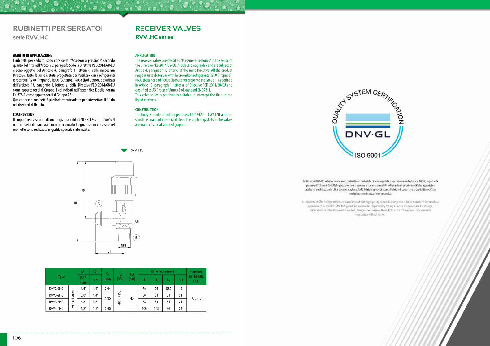
106
RUBINETTI PER SERBATOI RECEIVER VALVESserie RVV..HC RVV..HC series
RVV..HC
(A) (B)SAE Flare NPT H1 H2 L1 CH
RVV2-2HC 1/4" 1/4" 0,44 78 54 25,5 18
RVV3-2HC 3/8" 1/4" 86 61 31 21
RVV3-3HC 3/8" 3/8" 88 61 31 21
RVV4-4HC 1/2" 1/2" 3,40 108 108 36 24
Category 2014/68/EU
PED
TS [°C]Type
Art. 4.3
PS [bar]
Kv [m3/h]
1,35
Vertic
al va
lves
-20 ÷
+10
5
35
Dimensions [mm]
AMBITO DI APPLICAZIONEI rubinetti per serbatoi sono considerati “Accessori a pressione” secondo quanto definito nell’Articolo 2, paragrafo 5, della Direttiva PED 2014/68/EU e sono oggetto dell’Articolo 4, paragrafo 1, lettera c, della medesima Direttiva. Tutta la serie è stata progettata per l’utilizzo con i refrigeranti idrocarburi R290 (Propano), R600 (Butano), R600a (Isobutano), classificati dall’articolo 13, paragrafo 1, lettera a, della Direttiva PED 2014/68/EU come appartenenti al Gruppo 1 ed indicati nell’appendice E della norma EN 378-1 come appartenenti al Gruppo A3.Questa serie di rubinetti è particolarmente adatta per intercettare il fluido nei ricevitori di liquido.
COSTRUZIONEIl corpo è realizzato in ottone forgiato a caldo UNI EN 12420 – CW617N mentre l’asta di manovra è in acciaio zincato. Le guarnizioni utilizzate nel rubinetto sono realizzate in grafite speciale sinterizzata.
APPLICATIONThe receiver valves are classified “Pressure accessories” in the sense of the Directive PED 2014/68/EU, Article 2, paragraph 5 and are subject of Article 4, paragraph 1, letter c, of the same Directive. All the product range is suitable for use with hydrocarbon refrigerants R290 (Propane), R600 (Butane) and R600a (Isobutane) proper to the Group 1, as defined in Article 13, paragraph 1, letter a, of Directive PED 2014/68/EU and classified as A3 Group of Annex E of standard EN 378-1.This valve series is particularly suitable to intercept the fluid in the liquid receivers. CONSTRUCTIONThe body is made of hot forged brass EN 12420 – CW617N and the spindle is made of galvanized steel. The applied gaskets in the valves are made of special sintered graphite.
L1
H2
H1
CH
B
A
NPT
45
-40 ÷
+13
0