Muse: esce oggi il nuovo singolo 'Dig Down', accompagnato ...

Tecnologia di realizzazione delle infrastrutture interrate a basso impatto ambientale - Sistemi di minitrincea
Low environmental impact underground infrastructure technology - Mini-trenching systems
La prassi di riferimento fornisce specificazione descrittiva delle pratiche attuate per la realizzazione di infrastrutture interrate mediante tecnologia di minitrincea, per ogni soggetto operatore o Ente locale, al fine di una corretta gestione degli interventi nel sottosuolo, attraverso il loro coordinamento e la coerenza tecnica degli stessi.
This document provides a descriptive specification of the practices implemented in deploying underground infrastructures with the aid of mini-trenching technology, for use by single operators or local authorities, aimed at ensuring works below ground level are managed correctly, through proper coordination and verification of technical consistency.
ICS 93.020Pubblicata il 19 giugno 2014
PRASSI DI RIFERIMENTO UNI/PdR 7:2014

© UNIVia Sannio 2 – 20137 MilanoTelefono 02 700241 www.uni.com – [email protected]
Tutti i diritti sono riservati.
I contenuti possono essere riprodotti o diffusi (anche integralmente) a condizione che ne venga data comunicazione all’editore e sia citata la fonte.
Documento distribuito gratuitamente da UNI.
© UNIVia Sannio 2 – 20137 MilanPhone +39 02 700241 www.uni.com – [email protected]
All rights reserved.
The contents of the document (also the full version) may be duplicated or distributed provided that UNI is informed and quoted.
This document is distributed by UNI free of charge.

La presente prassi di riferimento UNI/PdR 7:2014 è pubblicata con testo inglese e italiano.

UNI/PdR 7:2014
© UNI 1
FOREWORD
The UNI/PdR 7:2014 does not have the status of a UNI technical standard, nor of a technical
specification UNI/TS or technical report UNI/TR it is, instead, a document developed under the
authority of UNI and adopting the requirements related to practices shared by the following
proposers who have signed an agreement of collaboration with UNI:
IATT – Italian Association for Trenchless Technology
Via Ruggero Fiore, 41
00136 Roma
UNINDUSTRIA – Unione degli Industriali e delle Imprese Roma, Frosinone, Latina,
Rieti, Viterbo
Via Andrea Noale, 206
00155 Roma
This UNI/PdR has been developed by the working group “Minitrincea”, led by UNI and constituted
by the following experts:
PAOLA FINOCCHI - Project Leader (Telecom Italia/IATT)
FRANCESCO CECERA (Telecom Italia/IATT)
EDOARDO COTTINO (Sirti/IATT)
ANGELO MACCARONE (Fastweb/IATT)
FLAVIO PADOVANI (Vermeer Italia/IATT)
GIOVACCHINO ROSATI (New Font/IATT)
PAOLO TROMBETTI (IATT)
ANTONIO TRUGLIO (UNINDUSTRIA)
DOMENICO VIOLA (Idroambiente/UNIPLAST)
This UNI/PdR has been ratified by UNI President on 18 June 2014.
UNI/PdRs are documents introducing technical requirements that are developed through a fast track process
reflecting the consensus of the participants only, under the operational direction of UNI.
UNI/PdRs are valid for a limited duration of 5 years or until its transformation into another deliverable (UNI,
UNI/TS, UNI/TR) whichever is the sooner. When 5 years have passed, the UNI/PdR shall be withdrawn if it is
not transformed into another deliverable.
Further to the application of this UNI/PdR, anyone interested in providing suggestions for its improvement is
requested to send their own contributions to UNI, Italian Organization for Standardization, which shall take
them into account.

UNI/PdR 7:2014
© UNI 2
PREMESSA
La presente prassi di riferimento UNI/PdR 7:2014 non è una norma tecnica UNI, una specifica
tecnica UNI/TS o un rapporto tecnico UNI/TR, ma è un documento elaborato da UNI che raccoglie
prescrizioni relative a prassi condivise dai seguenti soggetti firmatari di un accordo di collaborazione
con UNI:
IATT – Italian Association for Trenchless Technology
Via Ruggero Fiore, 41
00136 Roma
UNINDUSTRIA – Unione degli Industriali e delle Imprese Roma, Frosinone, Latina,
Rieti, Viterbo
Via Andrea Noale, 206
00155 Roma
La presente prassi di riferimento è stata elaborata dal Tavolo “Minitrincea”, condotto da UNI,
costituito dai seguenti esperti:
PAOLA FINOCCHI - Project Leader (Telecom Italia/IATT)
FRANCESCO CECERA (Telecom Italia/IATT)
EDOARDO COTTINO (Sirti/IATT)
ANGELO MACCARONE (Fastweb/IATT)
FLAVIO PADOVANI (Vermeer Italia/IATT)
GIOVACCHINO ROSATI (New Font/IATT)
PAOLO TROMBETTI (IATT)
ANTONIO TRUGLIO (UNINDUSTRIA)
DOMENICO VIOLA (Idroambiente/UNIPLAST)
La presente prassi di riferimento è stata ratificata dal Presidente dell’UNI il 18 giugno 2014.
Le prassi di riferimento UNI sono documenti che introducono prescrizioni tecniche, elaborati sulla base di un
rapido processo di condivisione ristretta ai soli autori, sotto la conduzione operativa di UNI.
Le prassi di riferimento sono disponibili per un periodo non superiore a 5 anni, tempo massimo dalla loro
pubblicazione entro il quale possono essere trasformate in un documento normativo (UNI, UNI/TS, UNI/TR)
oppure devono essere ritirate.
Chiunque ritenesse, a seguito dell’applicazione della presente prassi di riferimento, di poter fornire
suggerimenti per un suo miglioramento è pregato di inviare i propri contributi all’UNI, Ente Nazionale Italiano
di Unificazione, che li terrà in considerazione.

UNI/PdR 7:2014
© UNI 3
CONTENTS
INTRODUCTION .......................................................................................................................................................... 7
1 SCOPE ........................................................................................................................................................... 11
2 NORMATIVE REFERENCES ........................................................................................................................ 11
3 TERMS AND DEFINITIONS .......................................................................................................................... 13
4 PRINCIPLE ..................................................................................................................................................... 13
5 PRELIMINARY UNDERGROUND SURVEY ................................................................................................. 15
6 MINI-TRENCH ................................................................................................................................................ 17
6.1 GENERAL ...................................................................................................................................................... 17
6.2 TYPES OF MACHINES AND MATERIALS UTILIZED ................................................................................. 19
6.2.1 MACHINES ................................................................................................................................................. 19
6.2.2 BACKFILL MATERIALS ............................................................................................................................ 21
6.3 MINI-TRENCHING PROCEDURE ................................................................................................................. 23
6.3.1 EXCAVATION ............................................................................................................................................ 23
6.3.2 CLEANING THE MINI-TRENCH ................................................................................................................ 23
6.3.3 LAYING THE INFRASTRUCTURE ............................................................................................................ 25
6.3.4 BACKFILL .................................................................................................................................................. 27
6.3.5 MARKING THE MINI-TRENCH ................................................................................................................. 29
6.3.6 REINSTATEMENT ..................................................................................................................................... 31
6.3.7 CONNECTION TO ACCESS CHAMBERS ................................................................................................ 33
7 NARROW-MINI-TRENCH .............................................................................................................................. 33
7.1 GENERAL ...................................................................................................................................................... 33
7.2 TYPES OF MACHINES AND MATERIALS UTILIZED ................................................................................. 37
7.2.1 MACHINES ................................................................................................................................................. 37
7.2.2 BACKFILL MATERIALS ............................................................................................................................ 41
7.3 NARROW-MINI-TRENCHING PROCEDURE................................................................................................ 43
7.3.1 EXCAVATION ............................................................................................................................................ 43
7.3.2 CLEANING THE NARROW-MINI-TRENCH .............................................................................................. 43
7.3.3 LAYING THE INFRASTRUCTURE ............................................................................................................ 45
7.3.4 BACKFILL .................................................................................................................................................. 45

UNI/PdR 7:2014
© UNI 4
7.3.5 REINSTATEMENT ..................................................................................................................................... 47
7.3.6 CONNECTION TO ACCESS CHAMBERS ................................................................................................ 47
8 SAFETY .......................................................................................................................................................... 47
ANNEX A – MAIN LEGISLATIVE REFERENCES .................................................................................................... 49
BIBLIOGRAPHY ........................................................................................................................................................ 51

UNI/PdR 7:2014
© UNI 5
SOMMARIO
INTRODUZIONE .......................................................................................................................................................... 8
1 SCOPO E CAMPO DI APPLICAZIONE ........................................................................................................ 12
2 RIFERIMENTI NORMATIVI............................................................................................................................ 12
3 TERMINI E DEFINIZIONI ............................................................................................................................... 14
4 PRINCIPIO ..................................................................................................................................................... 14
5 INDAGINE PREVENTIVA DEL SOTTOSUOLO............................................................................................ 16
6 MINITRINCEA ................................................................................................................................................ 18
6.1 GENERALITÀ ................................................................................................................................................ 18
6.2 TIPOLOGIA DI MEZZI E MATERIALI UTILIZZATI ....................................................................................... 20
6.2.1 MEZZI ......................................................................................................................................................... 20
6.2.2 MATERIALI DI RIEMPIMENTO ................................................................................................................. 22
6.3 MODALITÀ DI ESECUZIONE DELLA MINITRINCEA .................................................................................. 24
6.3.1 SCAVO ....................................................................................................................................................... 24
6.3.2 PULIZIA DELLA MINITRINCEA ................................................................................................................ 24
6.3.3 POSA DELL’INFRASTRUTTURA ............................................................................................................. 26
6.3.4 RIEMPIMENTO .......................................................................................................................................... 28
6.3.5 SEGNALAZIONE DELLA MINITRINCEA ................................................................................................. 30
6.3.6 RIPRISTINO ............................................................................................................................................... 32
6.3.7 INGRESSO NEI MANUFATTI .................................................................................................................... 34
7 MINITRINCEA RIDOTTA ............................................................................................................................... 34
7.1 GENERALITÀ ................................................................................................................................................ 34
7.2 TIPOLOGIA DI MEZZI E MATERIALI UTILIZZATI ....................................................................................... 38
7.2.1 MEZZI ......................................................................................................................................................... 38
7.2.2 MATERIALI DI RIEMPIMENTO ................................................................................................................. 42
7.3 MODALITÀ DI ESECUZIONE DELLA MINITRINCEA RIDOTTA ................................................................. 44
7.3.1 SCAVO ....................................................................................................................................................... 44
7.3.2 PULIZIA DELLA MINITRINCEA RIDOTTA ............................................................................................... 44
7.3.3 POSA DELL’INFRASTRUTTURA ............................................................................................................. 46
7.3.4 RIEMPIMENTO .......................................................................................................................................... 46

UNI/PdR 7:2014
© UNI 6
7.3.5 RIPRISTINO ............................................................................................................................................... 48
7.3.6 INGRESSO NEI MANUFATTI .................................................................................................................... 48
8 SICUREZZA ................................................................................................................................................... 48
APPENDICE A – PRINCIPALI RIFERIMENTI LEGISLATIVI ................................................................................... 49
BIBLIOGRAFIA .......................................................................................................................................................... 52

UNI/PdR 7:2014
© UNI 7
INTRODUCTION
This document relates to the installation of infrastructures and utilities (pipes and/or cables) using
mini-trenching technology. More exactly, the document refers to so-called “trenchless”, or “no dig”,
or "low environmental impact" technologies, which can be employed for laying, reutilizing, upgrading
and replacing underground infrastructure and utility grids — typically water, telecommunications,
power and drains — with little or no recourse to open cut excavation.
Internationally, these technologies are recognized as making up five macro families:
a) surveying technologies;
b) directional drilling technologies;
c) non-directional drilling technologies;
d) technologies for upgrading and repairing networks;
e) associated technologies.
Mini-trenching belongs to the family of "associated technologies" and is used mainly for installing
telecom cable networks, water supply mains, and electrical power grids such as street lighting and
traffic signalling systems.
Like all trenchless technologies, mini-trenching affords the advantage — compared to traditional
excavation — of significantly reduced social and environmental impact, lower energy requirements,
and better levels of safety both for workers on site and for passers-by in the immediate vicinity of the
site.
Figure 1 – Minimal impact of mini-trenching on road traffic
UNI/PdR 7:2014
© UNI 8
INTRODUZIONE
Il presente documento fa riferimento alla realizzazione di infrastrutture (tubi e/o cavi) con la
tecnologia della minitrincea. Tale tecnologia rientra nelle cosiddette “trenchless technologies”,
anche dette “no dig” o “a basso impatto ambientale”, che permettono di effettuare la posa, il
riutilizzo, il risanamento e la sostituzione delle reti dei sottoservizi, tipicamente acqua,
telecomunicazioni, energia e fognature, con un nullo o limitato ricorso agli scavi a cielo aperto.
In ambito internazionale queste tecnologie vengono raggruppate in cinque macro famiglie:
a) tecnologie conoscitive;
b) tecnologie di posa orizzontali guidate;
c) tecnologie di posa non guidate;
d) tecnologie per il risanamento e riparazione delle reti;
e) tecnologie associate.
La tecnologia della minitrincea appartiene alla famiglia delle “tecnologie associate” e viene utilizzata
principalmente per realizzare reti di telecomunicazione, reti idriche ed elettriche quali la pubblica
illuminazione e i sistemi semaforici.
Come tutte le tecnologie trenchless, la minitrincea, rispetto allo scavo tradizionale, ha la
caratteristica di ridurre drasticamente gli impatti socio ambientali, il consumo energetico e di
migliorare i livelli di sicurezza del personale presente in cantiere e di quanti si trovino a transitare
nelle sue immediate vicinanze.
Figura 1 – Impatto minimo della tecnologia sulla circolazione stradale

UNI/PdR 7:2014
© UNI 9
This UNI/PdR reflects the need to create technical reference documents for cutting trenches of
minimal dimensions, available to operators or local authorities, with the end in view of ensuring that
works below ground level are managed correctly.
Italian legislation — notably Presidential Decree n° 207 of 5 October 2010, Rules for enacting and
implementing Legislative Decree n° 163 of 12 April 2006, also sundry decrees aiding development
and growth in Italy — promotes the use of trenchless technologies, and in particular mini-trenching,
which are defined as mini excavation technologies with low environmental impact to highlight their
advantages for the community.

UNI/PdR 7:2014
© UNI 10
La prassi di riferimento nasce dalla necessità di creare documenti tecnici di riferimento per la
realizzazione di trincee di dimensioni ridotte, per ogni operatore o Ente locale, al fine di una corretta
gestione degli interventi nel sottosuolo.
La legislazione italiana – attraverso il D.P.R. 5 ottobre 2010, n. 207 Regolamento di esecuzione ed
attuazione del decreto legislativo 12 aprile 2006, n. 163 e i diversi decreti volti a incentivare lo
sviluppo e la crescita del Paese - promuove l’impiego delle tecnologie trenchless e, in particolare,
della minitrincea, denominandole tecnologie di miniscavo a basso impatto ambientale per
evidenziarne i vantaggi sulla collettività.
UNI/PdR 7:2014
© UNI 11
1 SCOPE
This UNI/PdR provides a descriptive specification of the practices implemented in deploying
underground infrastructures with the aid of mini-trenching technology, for use by single operators or
local authorities, aimed at ensuring works below ground level are managed correctly, through
proper coordination and verification of technical consistency.
This document describes the techniques connected with excavating and backfilling small trenches,
laying pipes/cables and reinstating road surfaces; it also indicates the equipment utilized and the
application limits.
The following are excluded from the scope of this UNI/PdR:
grids and networks of which the regulations envisage installation at a depth greater than that
specified for mini-trenching methods;
technologies other than those associated with mini-trenching, such as traditional open cut
excavation;
gas mains, which are subject to specific regulations.
2 NORMATIVE REFERENCES
This UNI/PdR makes reference, by dated and undated references, to provisions contained in other
publications. These normative references are cited at the appropriate points in the text and listed
below. For dated references, subsequent amendments or revisions made to any of these
publications apply only when cited in the present document as update or review. For undated
references, the latest edition of the referenced publication applies.
UNI 10576 Protezione delle tubazioni gas durante i lavori nel sottosuolo
UNI EN 12390-3 Testing hardened concrete - Part 3: Compressive strength of test specimens
UNI EN 13687-3 Products and systems for the protection and repair of concrete structures -
Test methods - Determination of thermal compatibility - Part 3: Thermal cycling without de-icing
salt impact
UNI EN 13892-3 Methods of test for screed materials - Part 3: Determination of wear
resistance-Böhme

UNI/PdR 7:2014
© UNI 12
1 SCOPO E CAMPO DI APPLICAZIONE
La presente prassi di riferimento fornisce specificazione descrittiva delle pratiche attuate per la
realizzazione di infrastrutture interrate mediante tecnologia di minitrincea, per ogni soggetto
operatore o Ente locale, al fine di una corretta gestione degli interventi nel sottosuolo, attraverso il
loro coordinamento e la coerenza tecnica degli stessi.
Tale documento descrive le tecniche connesse alle attività di scavo e di riempimento delle trincee di
dimensioni ridotte, la posa dell’infrastruttura, il ripristino delle superfici stradali, i relativi strumenti
utilizzati e i limiti applicativi.
Sono esclusi dal campo di applicazione della prassi di riferimento:
le reti dei servizi le cui normative contemplino una posa a profondità superiore di quella
definita per la tecnica della minitrincea;
le tecnologie differenti da quelle delle trincee ridotte come, per esempio, lo scavo
tradizionale “a cielo aperto”;
le reti del servizio gas, soggette a normativa specifica.
2 RIFERIMENTI NORMATIVI
La presente prassi di riferimento rimanda, mediante riferimenti datati e non, a disposizioni contenute
in altre pubblicazioni. Tali riferimenti normativi sono citati nei punti appropriati del testo e sono di
seguito elencati. Per quanto riguarda i riferimenti datati, successive modifiche o revisioni apportate
a dette pubblicazioni valgono unicamente se introdotte nel presente documento come
aggiornamento o revisione. Per i riferimenti non datati vale l'ultima edizione della pubblicazione alla
quale si fa riferimento.
UNI 10576 Protezione delle tubazioni gas durante i lavori nel sottosuolo
UNI EN 12390-3 Prove sul calcestruzzo indurito - Parte 3: Resistenza alla compressione dei
provini
UNI EN 13687-3 Prodotti e sistemi per la protezione e la riparazione delle strutture di
calcestruzzo - Metodi di prova - Determinazione della compatibilità termica - Cicli termici senza
immersione in sali disgelanti
UNI EN 13892-3 Metodi di prova per materiali per massetti - Parte 3: Determinazione della
resistenza all'usura con il metodo Böhme

UNI/PdR 7:2014
© UNI 13
3 TERMS AND DEFINITIONS
For the purpose of this document, the following terms and definitions apply.
3.1 infrastructure: Cables, pipelines or access chambers laid underground.
3.2 chamber: Pit or enclosure located underground and designed so as to allow internal access for
the purposes of laying, joining and branching cables and pipelines, as well as operating items of
equipment and accessory devices that may be installed within the enclosure.
3.3 mini-trench: Trenchless technology allowing the installation of utility grids by cutting a channel
of minimal width in the road surface, laying pipes and/or cables simultaneously with or following the
cut, and backfilling with cement mortar.
3.4 underground utility grids: Primary service networks, typically telecommunications, routed
through special ducts laid underground.
3.5 trenchless technologies: Technologies characterized by low environmental impact, allowing
the renewal, upgrade or installation of existing or new infrastructures with minimal open cut
excavation.
4 PRINCIPLE
This UNI/PdR specifies detailed technical requirements relating to mini-trenching operations carried
out by installation contractors for the account of single operators or local authorities, to the end of
ensuring that works below ground level are managed correctly.
Using trenchless methods, cables and pipelines can be laid underground swiftly and with minimal
impact either on the environment or on the community. Compared to traditional methods, in effect,
these methods significantly reduce the time needed for occupation of the road site and completion
of the work. Mini-trenching methods for laying pipes and cables can be used in both urban and
suburban areas, and are especially advantageous for locations characterized by high levels of road
traffic and business activity.
Depending on the dimensions of the infrastructure to be installed, and the location (optimization of
work sites), mini-trenching methods are divided into two macro categories:
a) mini-trench;
b) narrow-mini-trench.
This document specifies that, whatever the mini-trenching method adopted, in order to safeguard
existing infrastructures, a preliminary underground survey should be conducted using georadar
techniques, and the findings studied in conjunction with information supplied by other bodies and by
the site operator.

UNI/PdR 7:2014
© UNI 14
3 TERMINI E DEFINIZIONI
Ai fini del presente documento valgono i termini e le definizioni seguenti.
3.1 infrastruttura: Cavi, tubazioni o manufatti di contenimento posati nel sottosuolo.
3.2 manufatto: Pozzetto o cameretta ubicati nel sottosuolo e realizzati in modo da consentire
l’accesso al loro interno per le operazioni di posa, giunzione e derivazione dei cavi e delle tubazioni
nonché per l’azionamento delle apparecchiature e delle installazioni accessorie eventualmente
presenti negli stessi.
3.3 minitrincea: Tecnologia trenchless che permette la posa delle reti dei servizi attraverso
l’esecuzione contemporanea o meno di fresatura di dimensioni ridotte del manto stradale,
sistemazione dell’infrastruttura e/o cavi e riempimento con malta cementizia.
3.4 reti dei servizi o dei sottoservizi: Reti dei servizi primari, tipicamente telecomunicazioni,
incanalati in apposite condutture realizzate nel sottosuolo.
3.5 tecnologie trenchless: Tecnologie a basso impatto ambientale che consentono il rinnovo, il
risanamento e la realizzazione di nuove reti di servizi limitando gli scavi a cielo aperto.
4 PRINCIPIO
La prassi di riferimento specifica le prescrizione tecniche volte a dettagliare la realizzazione di
minitrincee, da parte di imprese esercenti attività di posa di reti, per ogni soggetto operatore o Ente
locale, al fine di una corretta gestione degli interventi nel sottosuolo.
Le tecniche di posa mediante minitrincea permettono di intervenire nel sottosuolo in maniera rapida
e con un minimo impatto sull’ambiente e sulla collettività. Infatti, tali tecniche riducono
drasticamente, rispetto agli interventi tradizionali, i tempi di realizzazione e l’occupazione della
superficie stradale. Le tecniche di posa mediante minitrincea possono essere impiegate sia in aree
urbane sia extraurbane e sono particolarmente indicate anche dove il traffico veicolare e la
presenza di attività commerciali sono intense.
A seconda delle dimensioni dell’infrastruttura da posare e del luogo di intervento (ottimizzazione dei
cantieri), le tecniche di posa mediante minitrincea sono distinte in due macro-categorie:
a) minitrincea;
b) minitrincea ridotta.
Il documento specifica che, per qualunque tecnica di minitrincea, al fine di salvaguardare le
infrastrutture esistenti, è opportuno svolgere un’indagine preventiva del sottosuolo attraverso
tecniche georadar, correlata alle informazioni fornite da altri Enti e dal gestore del suolo in cui si
interviene.

UNI/PdR 7:2014
© UNI 15
The document also describes the type of machinery and materials to be employed and the mini-
trenching and narrow-mini-trenching methods to be adopted, covering the various steps of cutting,
cleaning/dust extraction, laying, backfilling and marking the trench, and reinstatement of the site to
its previous condition.
Annex A lists the main legislative references pertinent to mini-trenching technologies.
5 PRELIMINARY UNDERGROUND SURVEY
Mini-trenching procedures are characterized by the use of a cutting tool engaging the ground in
such a way that the operator cannot be warned in time if there are areas along the path of the cut
already occupied by pipes or cables, which consequently risk being damaged. Accordingly, it is
essential that underground surveys are carried out beforehand so as to verify whether or not there
are utilities already in place, and if so, ensure that the appropriate precautionary measures are
adopted. In this regard, with reference to the protection of gas pipelines during underground works,
the UNI 10576 applies.
The preliminary geophysical survey serves to gather information on the nature and the structure of
the subsoil, provided by a set of measurements taken from above ground. These measurements
relate to certain physical parameters characteristic of the stone and other material in the subsoil,
such as electrical resistivity, density, elastic and dielectric constants, magnetic susceptibility.
The collection of data and their subsequent processing and interpretation enable to reconstruct the
structure and composition of the subsoil and formulate hypotheses as to the nature and geometry of
any buried objects.
The selection of the geophysical methodology to adopt is heavily influenced by the depth of the
survey and the lithology and state of the ground.
Georadar, or Ground Penetrating Radar (GPR), is one of the systems most widely used for
conducting geophysical surveys on soils, and its fields of application are many and various: it can
be used advantageously for identifying geological structures, locating ground water levels, karst
cavities and underground utilities, also for archaeological surveys and any other procedures serving
to identify and differentiate between materials contained in the subsoil.
The operation of GPR is based on the ability of an instrument to transmit radio frequency signals
into the ground and record the rebounds from objects buried beneath the surface, characterized by
electromagnetic properties different from those of the soil in which they are embedded. Any objects
present in the subsoil generate characteristic hyperbolic shapes in the radar images.
Schematically, the typical GPR system comprises:

UNI/PdR 7:2014
© UNI 16
La prassi di riferimento descrive la tipologia dei mezzi e materiali da utilizzarsi e le modalità di
esecuzione della minitrincea e della minitrincea ridotta, con riferimento alle fasi di scavo,
pulizia/aspirazione, posa dell’infrastruttura, riempimento, segnalazione e ripristino della sede dove
si è intervenuti.
L’Appendice A riporta l’elenco delle principali disposizioni di legge di riferimento per le tecnologie di
minitrincea.
5 INDAGINE PREVENTIVA DEL SOTTOSUOLO
Le attività di scavo con sistemi di minitrincea sono caratterizzate dall’utilizzo di un mezzo fresa, che
non permette all’operatore di avvedersi in tempo se la zona di scavo è attraversata da sottoservizi
con conseguente pericolo di danneggiamento delle reti esistenti. Per questo motivo è indispensabile
effettuare le indagini preventive del sottosuolo, in modo da verificare l’eventuale presenza di reti di
sottoservizi e adottare gli opportuni accorgimenti preventivi. A tale proposito, è di riferimento la UNI
10576 in materia di protezione delle tubazioni gas durante i lavori nel sottosuolo.
L’indagine geofisica preventiva allo scavo ha come scopo quello di ottenere informazioni sulla
natura e sulla struttura del sottosuolo attraverso una serie di misure effettuate dalla superficie. Tali
misure riguardano alcuni parametri fisici caratteristici delle rocce e dei materiali presenti nel
sottosuolo, come la resistività elettrica, la densità, le costanti elastiche e dielettriche, la suscettività
magnetica.
La raccolta dei dati, le successive fasi di elaborazione e interpretazione, consentono di ricostruire la
struttura e composizione del sottosuolo e di formulare ipotesi sulla natura e la geometria degli
eventuali oggetti sepolti.
La scelta del tipo di metodologia geofisica da adottare è fortemente condizionata dalla profondità di
indagine e dalla litologia e dallo stato del terreno.
Il Georadar, definito anche Ground Penetrating Radar (GPR), è uno tra i sistemi più utilizzati per le
indagini geofisiche dei terreni e i suoi campi di applicazione sono moltissimi e vari: può essere
utilizzato con successo per l'individuazione di strutture geologiche, per la localizzazione di superfici
freatiche, di cavità carsiche, di reti di sottoservizi, per indagini archeologiche e per quant’altro
implichi la conoscenza di differenziazioni nei materiali del sottosuolo.
Il funzionamento di un GPR si basa sulle capacità dello strumento di emettere segnali a
radiofrequenza nel sottosuolo e registrare quelli riflessi dagli oggetti interrati, caratterizzati da
proprietà elettromagnetiche diverse da quelle del terreno che li circonda. Eventuali oggetti presenti
nel sottosuolo generano nelle immagini radar caratteristiche forme iperboliche.
Schematicamente, il Georadar è costituito da:

UNI/PdR 7:2014
© UNI 17
a) a control unit (battery powered) to which the antennas are connected by way of special
cables;
b) one or two antennas, or an array of antennas, serving to transmit electromagnetic pulses
and capture the reflected or refracted signals;
c) a data acquisition and archiving unit.
Examples of GPR machines and map generation are shown in Figure 2.
Figure 2 – Examples of radar machines and map generation
6 MINI-TRENCH
6.1 GENERAL
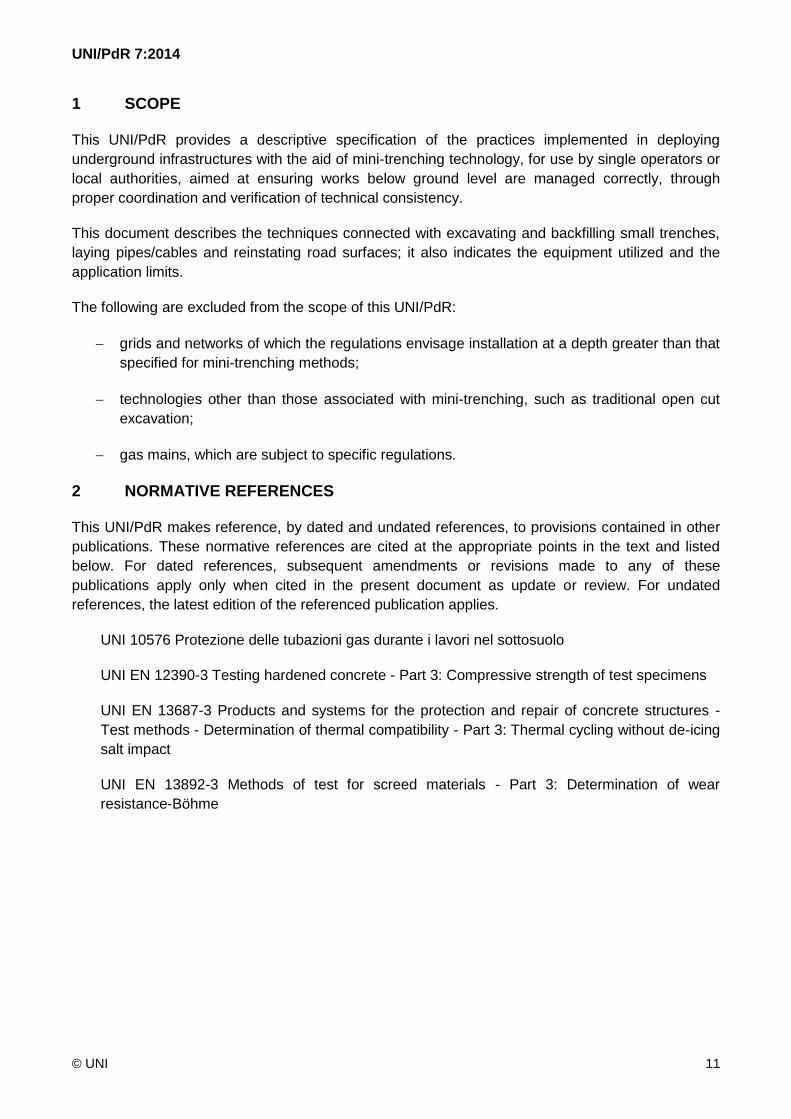
A mini-trench is created by cutting a channel to a nominal width greater than 5 cm but no greater
than 20 cm, and to a nominal depth of between 35 cm and no more than 50 cm (see Figure 3).

UNI/PdR 7:2014
© UNI 18
a) una unità di controllo (alimentata da una batteria) alla quale, tramite cavi di particolari
caratteristiche, sono collegate le antenne;
b) una, due o un array di antenne, che hanno la funzione di inviare impulsi elettromagnetici e
captare i segnali riflessi o rifratti;
c) una unità di acquisizione e di archivio dei dati raccolti.
Esempi di macchine radar e di generazione della mappa sono rappresentati in Figura 2.
Figura 2 – Esempi di macchine radar e di generazione della mappa
6 MINITRINCEA
6.1 GENERALITÀ
La minitrincea deve essere realizzata effettuando uno scavo di larghezza nominale maggiore di
5 cm e minore/uguale di 20 cm e profondità nominale da 35 cm fino ad un massimo di 50 cm
(vedere Figura 3).
UNI/PdR 7:2014
© UNI 19
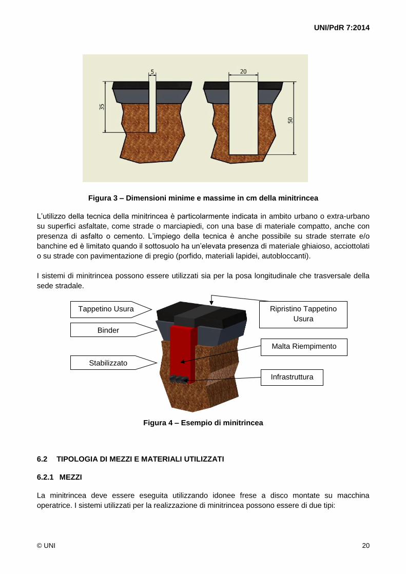
Figure 3 – Minimum and maximum dimensions of the mini-trench, in cm
The use of mini-trenching technology is especially suitable in urban or suburban locations, on
asphalted surfaces such as carriageways and footways, having a base of compact material, which
may include asphalt or concrete. The method is also suitable for unmetalled roads and/or verges
but is limited when the ground contains a high proportion of gravel, or on cobblestones, or on
surfaces with superior quality paving (porphyry, stone slabs, keyblock).
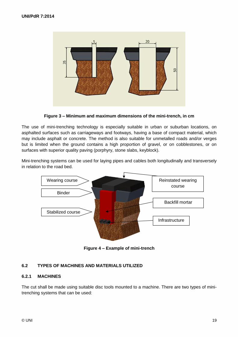
Mini-trenching systems can be used for laying pipes and cables both longitudinally and transversely
in relation to the road bed.
Figure 4 – Example of mini-trench
6.2 TYPES OF MACHINES AND MATERIALS UTILIZED
6.2.1 MACHINES
The cut shall be made using suitable disc tools mounted to a machine. There are two types of mini-
trenching systems that can be used:
Wearing course
Binder
Stabilized course
Reinstated wearing
course
Backfill mortar
Infrastructure
UNI/PdR 7:2014
© UNI 20
Figura 3 – Dimensioni minime e massime in cm della minitrincea
L’utilizzo della tecnica della minitrincea è particolarmente indicata in ambito urbano o extra-urbano
su superfici asfaltate, come strade o marciapiedi, con una base di materiale compatto, anche con
presenza di asfalto o cemento. L’impiego della tecnica è anche possibile su strade sterrate e/o
banchine ed è limitato quando il sottosuolo ha un’elevata presenza di materiale ghiaioso, acciottolati
o su strade con pavimentazione di pregio (porfido, materiali lapidei, autobloccanti).
I sistemi di minitrincea possono essere utilizzati sia per la posa longitudinale che trasversale della
sede stradale.
Figura 4 – Esempio di minitrincea
6.2 TIPOLOGIA DI MEZZI E MATERIALI UTILIZZATI
6.2.1 MEZZI
La minitrincea deve essere eseguita utilizzando idonee frese a disco montate su macchina
operatrice. I sistemi utilizzati per la realizzazione di minitrincea possono essere di due tipi:
Tappetino Usura
Binder
Stabilizzato
Ripristino Tappetino
Usura
Malta Riempimento
Infrastruttura

UNI/PdR 7:2014
© UNI 21
a) single machines performing successive steps, namely: trencher with disc cutter, machine for
collection of spoil, underground cable/pipe laying machine, concrete mixer or similar for
backfilling the trench;
b) combination trenching-laying-backfilling machines. The system shall comprise essentially the
following units:
a machine for cutting the trench;
a dumper truck equipped with a dust extraction system, for collection of the spoil;
a hopper, mounted to a vehicle or directly to a concrete mixer truck, for backfilling the
trench.
Figure 5 – Example of machine for mini-trench
6.2.2 BACKFILL MATERIALS
The material used to backfill the trench shall be a concrete mix (indicatively containing 200 kg/m3
cement ) prepared with suitable foaming and aerating additives, designed to produce a structure
having characteristics as similar as possible to those of the existing subsoil. The requisite technical
specifications of the backfill concrete are as follows:
a) compressive strength (to UNI EN 12390-3):
after 24 hours: between 5 and 10 N/mm2;
after 28 days: between 15 and 20 N/mm2;
b) specific gravity: between 1500 and 1800 kg/m3;
c) water absorption: between 150 and 180 kg/m3.

UNI/PdR 7:2014
© UNI 22
a) mezzi singoli, che lavorano in fasi successive, quali: macchina con fresa a disco, macchina
per recupero materiale di risulta, mezzo per posa infrastruttura, betoniera o similare per
riempimento dello scavo;
b) mezzi per l’esecuzione integrata di scavo, posa tubi e rinterro. Il sistema deve essere
composto principalmente dalle seguenti unità:
una macchina per l’esecuzione dello scavo della minitrincea;
un autocarro dotato di dispositivo aspiratore e cassone per lo stoccaggio del
materiale di risulta dello scavo;
una tramoggia, da abbinare a un autocarro o direttamente a un’autobetoniera, per il
riempimento dello scavo.
Figura 5 – Esempio di macchina di minitrincea
6.2.2 MATERIALI DI RIEMPIMENTO
Il materiale per il riempimento della trincea deve essere un conglomerato cementizio (valore
indicativo: cemento 200 kg/m3) opportunamente additivato con prodotti ad azione schiumogena e
aeranti, atti a determinare una struttura il più possibile simile alle caratteristiche del sottofondo
esistente. Le caratteristiche tecniche del conglomerato cementizio per il riempimento devono essere
le seguenti:
a) resistenza a compressione (secondo la UNI EN 12390-3):
dopo 24 ore: compresa tra 5 e 10 N/mm2;
dopo 28 gg: compresa tra 15 e 20 N/mm2;
b) massa volumica: variabile tra 1500 e 1800 kg/m3;
c) assorbimento di acqua: compreso tra 150 e 180 kg/m3.

UNI/PdR 7:2014
© UNI 23
The concrete mix, prepared to the specifications indicated above, shall guarantee the following
quality-related performance characteristics:
a) volumetric stability;
b) adhesion to trench walls and to infrastructure components;
c) complete filling of the envisaged excavated volume;
d) elimination of differential subsidence;
e) curing times and development of rated strength such as will allow reinstatement of the road bed 24 hours after backfilling;
f) compressive strength sufficient to withstand the stresses deriving from heavy and light traffic;
g) permeability to gases and liquids;
h) ease of re-excavation;
i) high workability (stability and cohesion when mixed, flowability allowing delivery with concrete pump).
In addition to holding the infrastructure firmly in place at the bottom of the trench, the backfill
material shall also ensure a high degree of mechanical protection.
6.3 MINI-TRENCHING PROCEDURE
The route followed by the trench shall be linear as far as possible, with no sharp changes in
direction, and shall not exceed the minimum bending radius specified for the infrastructure and/or
underground utility laid at the bottom of the channel.
6.3.1 EXCAVATION
The mini-trench is formed in a single operation that involves wrecking the surface of the carriageway
or footway and simultaneously cutting a channel of cross section proportioned to accommodate the
infrastructure and/or underground utility.
6.3.2 CLEANING THE MINI-TRENCH
The step of cleaning the trench shall be implemented immediately after making the cut. This step
involves the following operations:
a) removal of spoil from the edges of the cut. Spoil shall be disposed of only at authorized
landfill sites, proceeding in accordance with current statutory regulations;
b) removal of fragments lying adjacent to the trench, generated by damage to the paving or
wearing course during excavation;
c) cleaning the bottom of the mini-trench.

UNI/PdR 7:2014
© UNI 24
Il conglomerato, realizzato secondo le caratteristiche sopra descritte, deve garantire le seguenti
prestazioni di qualità:
a) stabilità volumetrica;
b) adesione alle pareti dello scavo e alle infrastrutture;
c) completo riempimento del volume previsto nello scavo;
d) eliminazione di cedimenti differenziati;
e) tempi di presa ed uno sviluppo delle resistenze tali da permettere il ripristino delle sedi stradali dopo le 24 ore dall’esecuzione del rinterro;
f) resistenza a compressione idonea a sopportare le sollecitazioni derivate dal traffico leggero e pesante;
g) permeabilità ai gas e ai liquidi;
h) facilità di rimozione;
i) elevata lavorabilità (stabilità e coesione all’impasto, fluidità tale da renderlo impiegabile mediante apposita pompa).
Il materiale di riempimento, oltre a bloccare l’infrastruttura sul fondo della minitrincea, deve avere la
funzione di garantire una protezione superiore di tipo meccanico.
6.3 MODALITÀ DI ESECUZIONE DELLA MINITRINCEA
Il percorso della minitrincea deve essere il più possibile lineare, esente da bruschi cambiamenti di
direzione, e tale da rispettare i raggi minimi di curvatura specificati per l’infrastruttura e/o il
sottoservizio da posizionare alla base dello scavo.
6.3.1 SCAVO
La minitrincea deve essere realizzata effettuando contemporaneamente il disfacimento della
pavimentazione e uno scavo avente una sezione di dimensione variabile in funzione
dell’infrastruttura e/o dei sottoservizi che deve contenere.
6.3.2 PULIZIA DELLA MINITRINCEA
La fase di pulizia della minitrincea deve essere eseguita successivamente alla fase di scavo. Tale
fase deve prevedere le attività seguenti:
a) rimozione dei materiali di risulta dai bordi dello scavo. I materiali di risulta devono essere
smaltiti presso discariche autorizzate secondo le modalità previste dalle leggi vigenti;
b) rimozione delle parti di pavimentazione adiacente allo scavo, danneggiata durante la fase di
scavo;
c) pulizia del fondo della minitrincea.

UNI/PdR 7:2014
© UNI 25
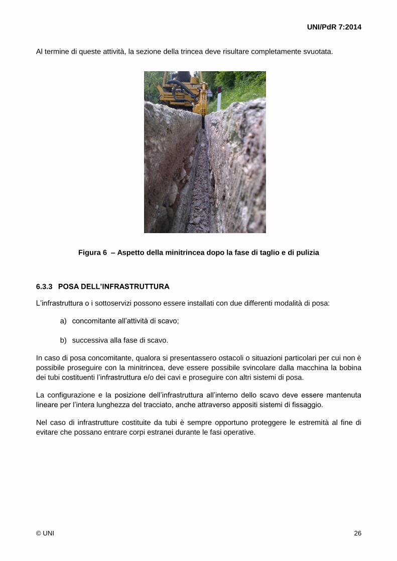
Following these operations, the cross section of the trench shall be completely clear.
Figure 6 – Appearance of mini-trench after cutting and cleaning
6.3.3 LAYING THE INFRASTRUCTURE
The infrastructure or underground utilities can be laid adopting two different methods:
a) simultaneously with excavation;
b) following excavation.
In the case of simultaneous trenching and laying, on encountering obstacles or particular situations
where work can no longer proceed, it shall be possible to release the reel of pipes and/or cables
from the machine or vehicle and switch to other laying systems.
The configuration and positioning of the infrastructure in the trench shall be controlled in such a way
that linear alignment is maintained along the entire length of the run, using appropriate fixing
systems if need be.
In the case of infrastructures consisting in pipelines, the pipe ends should always be protected to
prevent the risk of foreign matter entering when work is in progress.
UNI/PdR 7:2014
© UNI 26
Al termine di queste attività, la sezione della trincea deve risultare completamente svuotata.
Figura 6 – Aspetto della minitrincea dopo la fase di taglio e di pulizia
6.3.3 POSA DELL’INFRASTRUTTURA
L’infrastruttura o i sottoservizi possono essere installati con due differenti modalità di posa:
a) concomitante all’attività di scavo;
b) successiva alla fase di scavo.
In caso di posa concomitante, qualora si presentassero ostacoli o situazioni particolari per cui non è
possibile proseguire con la minitrincea, deve essere possibile svincolare dalla macchina la bobina
dei tubi costituenti l’infrastruttura e/o dei cavi e proseguire con altri sistemi di posa.
La configurazione e la posizione dell’infrastruttura all’interno dello scavo deve essere mantenuta
lineare per l’intera lunghezza del tracciato, anche attraverso appositi sistemi di fissaggio.
Nel caso di infrastrutture costituite da tubi è sempre opportuno proteggere le estremità al fine di
evitare che possano entrare corpi estranei durante le fasi operative.

UNI/PdR 7:2014
© UNI 27
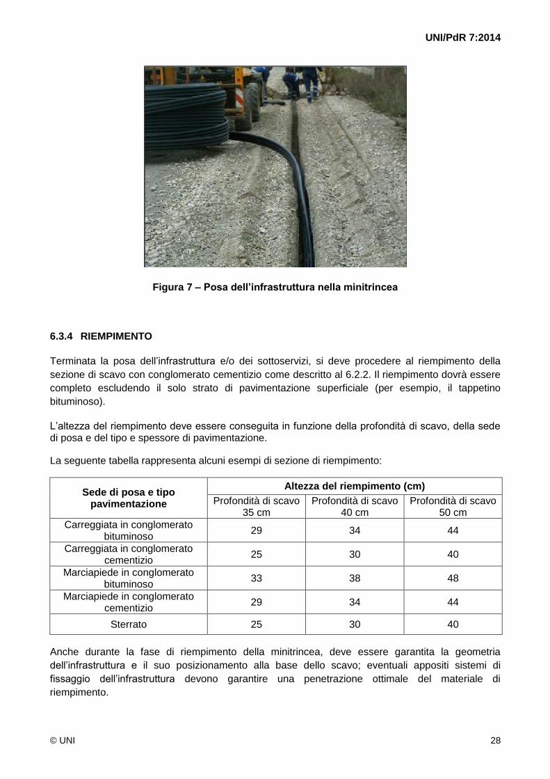
Figure 7 – Laying the infrastructure in the mini-trench
6.3.4 BACKFILL
Once the infrastructure and/or underground utilities have been laid, the open trench is backfilled
with a concrete mix as described in heading 6.2.2. The trench shall be backfilled up to the level of
the wearing course (e.g. bituminous asphalt surface).
The height of the backfill shall be gauged according to the depth of the excavation, the nature of the bed and the type and thickness of the surface.
The following table illustrates a few examples of backfill sections:
Nature of bed and type of surface
Height of backfill (cm)
Excavation depth 35 cm
Excavation depth 40 cm
Excavation depth 50 cm
Bituminous asphalt carriageway
29 34 44
Concrete carriageway
25 30 40
Bituminous asphalt footway
33 38 48
Concrete footway
29 34 44
Unmetalled road
25 30 40
Likewise during the backfill step, the geometry of the infrastructure and its correct positioning at the
bottom of the trench shall be maintained; any fixing systems used to secure the infrastructure in
place shall allow optimum penetration of the filling material, leaving no voids.
UNI/PdR 7:2014
© UNI 28
Figura 7 – Posa dell’infrastruttura nella minitrincea
6.3.4 RIEMPIMENTO
Terminata la posa dell’infrastruttura e/o dei sottoservizi, si deve procedere al riempimento della
sezione di scavo con conglomerato cementizio come descritto al 6.2.2. Il riempimento dovrà essere
completo escludendo il solo strato di pavimentazione superficiale (per esempio, il tappetino
bituminoso).
L’altezza del riempimento deve essere conseguita in funzione della profondità di scavo, della sede di posa e del tipo e spessore di pavimentazione.
La seguente tabella rappresenta alcuni esempi di sezione di riempimento:
Sede di posa e tipo pavimentazione
Altezza del riempimento (cm)
Profondità di scavo 35 cm
Profondità di scavo 40 cm
Profondità di scavo 50 cm
Carreggiata in conglomerato bituminoso
29 34 44
Carreggiata in conglomerato cementizio
25 30 40
Marciapiede in conglomerato bituminoso
33 38 48
Marciapiede in conglomerato cementizio
29 34 44
Sterrato 25 30 40
Anche durante la fase di riempimento della minitrincea, deve essere garantita la geometria
dell’infrastruttura e il suo posizionamento alla base dello scavo; eventuali appositi sistemi di
fissaggio dell’infrastruttura devono garantire una penetrazione ottimale del materiale di
riempimento.

UNI/PdR 7:2014
© UNI 29
The backfill material shall be deposited in the trench using a delivery system guaranteed not to soil
the inside faces of the surface layer, typically asphalt, that have been exposed by the action of the
cutting tool.
On completion of the backfill operation, in readiness for reinstatement of the surface, all necessary
precautions shall be taken (use of temporary structures, positioning of road signs, temporary filling
of excavation up to the level of the surface at particular locations such as crossings, etc.) in order to
ensure avoidance of danger situations and compliance with safety requirements, pending final
reinstatement of the surface.
Figure 7 bis – Filling with concrete mix
6.3.5 MARKING THE MINI-TRENCH
The following systems can be adopted for the purpose of marking the presence of the infrastructure
in the event of further excavation being planned:
a) addition of suitable additives (oxides) to the backfill cement mix, so as to produce a
distinctive colour that will not fade over time;
b) warning tape;
c) suitably visible external signage such as boards, stickers, etc., designed to indicate the
following main situations:
changes in direction of the infrastructure and/or utility, as near as possible to the system;
routing of straight line sections, marked at average distances no greater than 300 m,
prioritizing the placement of markers near road crossings, in order to maximize traceability.

UNI/PdR 7:2014
© UNI 30
La posa del materiale di riempimento all’interno dello scavo deve essere effettuata mediante
sistema idoneo a mantenere pulite le pareti interne dello strato superficiale, tipicamente in asfalto,
derivate dal disfacimento della pavimentazione.
Al termine delle opere di riempimento, in attesa dell’esecuzione dei ripristini della pavimentazione,
si devono prendere tutte le necessarie precauzioni (utilizzo di strutture provvisorie, mantenimento
delle protezioni segnaletiche, riempimento provvisorio dello scavo fino al livello stradale in situazioni
particolari come attraversamenti, ecc.) atte a evitare situazioni di pericolo e a garantire le condizioni
di sicurezza richieste fino alla realizzazione del ripristino definitivo della pavimentazione.
Figura 7 bis – Riempimento con conglomerato cementizio
6.3.5 SEGNALAZIONE DELLA MINITRINCEA
Al fine di evidenziare la presenza dell’infrastruttura in caso di future operazioni di scavo, possono
essere adottati i seguenti sistemi:
a) colorazione del conglomerato cementizio di riempimento mediante opportuni additivi (ossidi)
che dovrà mantenersi inalterata nel tempo;
b) nastro di segnalazione;
c) idonee segnalazioni esterne visibili quali tabelle, cartelli adesivi, ecc., atte a indicare le
seguenti principali situazioni:
cambi di direzione dell’infrastruttura e/o sottoservizio, il più vicino possibile all’impianto;
tracciato nei tratti rettilinei, a distanza mediamente non superiore ai 300 m,
privilegiando la segnalazione nelle vicinanze degli incroci stradali in modo da favorirne la
rintracciabilità.

UNI/PdR 7:2014
© UNI 31
Figure 8 – Example of colourant applied to concrete mix
6.3.6 REINSTATEMENT
Once 24 hours have passed following completion of the backfill, the part of the road surface
(wearing course) damaged by the trenching operation can be definitively reinstated.
When reinstating the carriageway or footway surface, operations shall be carried out observing the
directions given in headings 6.3.6.1 to 6.3.6.3.
The height of the repaired layer shall be gauged according to the nature of the bed and the type of
surface.
The following table indicates some examples of reinstatement height:
Nature of bed and type of surface Height of reinstated layer (cm)
Bituminous asphalt carriageway 6
Concrete carriageway 10
Bituminous asphalt footway 2
Concrete footway 6
Where particular conditions of the road dictate that the width of the area to be reinstated (wearing
course) needs to be extended beyond the edges of the excavated section, the extension shall be
consistent with the proportions of the actual damage. In particular, given the small cross sectional
dimensions of the mini-trench, it will be sufficient that the width of the repair is no greater than 50 cm
(25 cm right and 25 cm left of the excavation centre line).
6.3.6.1 REINSTATEMENT OF BITUMINOUS ASPHALT SURFACE ON CARRIAGEWAY OR
FOOTWAY
Where mini-trenches are cut in bases topped with bituminous asphalt, the surface shall be
reinstated once 24 hours have elapsed after backfilling; the procedure is as follows:

UNI/PdR 7:2014
© UNI 32
Figura 8 – Esempio di colorazione del conglomerato cementizio
6.3.6 RIPRISTINO
Trascorse almeno 24 ore dall’esecuzione del riempimento, si può procedere all’esecuzione del
ripristino definitivo dello strato di pavimentazione stradale (tappetino d’usura) manomesso.
L’attività di ripristino della pavimentazione della sede di posa deve essere eseguita rispettando le
indicazioni realizzative descritte da 6.3.6.1 a 6.3.6.3.
L’altezza del ripristino deve essere conseguita in funzione della sede di posa e del tipo di
pavimentazione.
La tabella seguente rappresenta alcuni esempi di altezza di ripristino:
Sede di posa e tipo di pavimentazione Altezza del ripristino (cm)
Carreggiata in conglomerato bituminoso 6
Carreggiata in conglomerato cementizio 10
Marciapiede in conglomerato bituminoso 2
Marciapiede in conglomerato cementizio 6
Qualora, per le particolari condizioni della strada, fosse necessario estendere la larghezza di
ripristino della pavimentazione stradale (tappetino di usura) oltre i bordi dello scavo, tale estensione
dovrà essere coerente con le proporzioni della manomissione effettuata. In particolare, per le
contenute dimensioni della sezione della minitrincea, è sufficiente che la larghezza del ripristino non
sia superiore a 50 cm (25 cm a destra e 25 cm a sinistra rispetto alla mezzeria dello scavo).
6.3.6.1 RIPRISTINO IN CONGLOMERATO BITUMINOSO SU CARREGGIATA O MARCIAPIEDE
I tratti di minitrincea eseguiti su pavimentazione in conglomerato bituminoso, trascorse le 24 ore
dall’esecuzione del riempimento, devono essere ripristinati nel modo seguente:

UNI/PdR 7:2014
© UNI 33
a) application of bitumen primer to all faces making up the contact area of the repair, and to the
edges of the trench, using a hot bituminous emulsion containing 50% bitumen; alternatively,
a cold elastomeric bituminous emulsion can be used provided that the performance
characteristics offered are equivalent to or better than those of a hot emulsion;
b) closure of the trench, covering with hot bituminous asphalt of grain size and overall depth
matched to the material of the existing surface;
c) rolling the new material until compressed to the level of the original asphalted surface.
6.3.6.2 REINSTATEMENT OF CONCRETE SURFACE ON CARRIAGEWAY OR FOOTWAY
Where mini-trenches are cut in bases topped with concrete, the surface shall be reinstated once 24
hours have elapsed after backfilling, with a cast in situ concrete mix having the same specifications
as that of the existing surface.
6.3.6.3 REINSTATEMENT OF UNMETALLED SURFACES
Where mini-trenches are cut in unmetalled roads, the surface shall be reinstated once 24 hours
have elapsed after backfilling; the top 10 cm of the trench is refilled with spoil from the excavation —
if suitable, or alternatively with aggregates — and compacted as necessary.
6.3.7 CONNECTION TO ACCESS CHAMBERS
Connection to an existing access chamber is accomplished by digging a traditional trench about 2
metres in length, creating a gentle gradient between the mini trench and the access points of the
chamber (knock-out sections) so that the minimum bending radius of the pipe will not be exceeded.
7 NARROW-MINI-TRENCH
7.1 GENERAL
A narrow-mini-trench is created by cutting a channel to a nominal width no greater than 5 cm, and to
a nominal depth of between 35 cm and no more than 50 cm (see Figure 9).
The narrow-mini-trench is characterized by:
a) flexible use of machinery proportioned to suit the particular site;
b) completion of work in quick time and with minimal occupation of road space;
c) cleanliness of site ensured by simultaneous trenching and dust extraction;
d) short duration of site permit;
e) immediate and complete backfill to datum level, with no need for further reinstatement
works.
UNI/PdR 7:2014
© UNI 34
a) esecuzione della bitumatura d’attacco su tutte le pareti costituenti la superficie di appoggio
del ripristino e sul bordo della minitrincea con impiego a caldo di emulsione bituminosa al
50% di bitume; in alternativa è possibile l’impiego di emulsione bituminosa elastomerizzata a
freddo purché garantisca prestazioni maggiori o uguali di quelle offerte dalla tecnica a caldo;
b) chiusura della minitrincea mediante la posa in opera di conglomerato bituminoso a caldo
avente granulometria e spessore analoghi a quelli del manto di usura esistente;
c) cilindratura del ripristino definitivo della pavimentazione con rullo a compressione fino a
raggiungere il livello stradale originario.
6.3.6.2 RIPRISTINO IN CONGLOMERATO CEMENTIZIO SU CARREGGIATA O MARCIAPIEDE
Il ripristino della minitrincea eseguita su pavimentazione in conglomerato cementizio, trascorse le 24
ore dall’esecuzione del riempimento, deve essere realizzato mediante la gettata in opera di
conglomerato cementizio avente caratteristiche simili a quello preesistente.
6.3.6.3 RIPRISTINO SU STERRATO
Per i tratti di minitrincea eseguiti su sterrato, trascorse le 24 ore dall’esecuzione del riempimento, gli
ultimi 10 cm della sezione di scavo devono essere riempiti utilizzando terra proveniente dallo scavo
stesso, se idonea, o con materiale inerte, opportunamente costipato.
6.3.7 INGRESSO NEI MANUFATTI
Il collegamento a un manufatto esistente deve essere realizzato mediante uno scavo di tipo
tradizionale della lunghezza di circa 2 m, che consenta una discesa graduale di raccordo tra la
minitrincea e i punti di accesso al manufatto (setti a frattura) nel rispetto del minimo raggio di
curvatura del tubo.
7 MINITRINCEA RIDOTTA
7.1 GENERALITÀ
La minitrincea ridotta deve essere realizzata effettuando uno scavo avente larghezza nominale
minore/uguale a 5 cm e profondità nominale da 35 cm fino a un massimo di 50 cm (vedere Figura
9).
La minitrincea ridotta è caratterizzata da:
a) uso flessibile di macchine con dimensioni adeguate al luogo di intervento;
b) minimizzazione dei tempi di esecuzione e di occupazione dello spazio stradale;
c) pulizia del cantiere, mediante la contemporaneità delle fasi di scavo e aspirazione;
d) rapidità di apertura e chiusura del cantiere;
e) riempimento immediato dello scavo, fino al piano di rotolamento, senza necessità di ulteriori
ripristini.

UNI/PdR 7:2014
© UNI 35
Figure 9 – Minimum and maximum dimensions of the narrow-mini-trench, in cm
The use of narrow-mini-trenching technology is especially suitable in urban or suburban locations,
on asphalted surfaces such as carriageways and footways, having a base of compact material that
may be topped with asphalt or concrete. The application of the method is limited when the ground
consists of gravel, or on cobblestones, or on surfaces with superior quality paving (porphyry, stone
slabs, keyblock).
Narrow-mini-trench systems can be used for laying pipes and cables both longitudinally and
transversely in relation to the road bed.
Figure 10 – Example of narrow-mini-trench
All steps of the narrow-mini-trenching procedure shall be implemented simultaneously, as far as
possible, with the aid of power units either operating in sequence or combined into one or more
machines, thereby enhancing the advantages of the technology in terms of speed and minimal
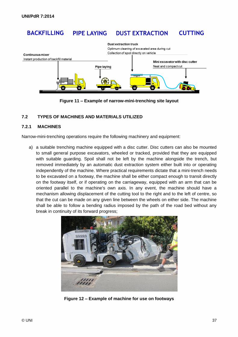
traffic disruption (see Figure 11).
Wearing course
Binder
Stabilized course
Backfill mortar
Infrastructure

UNI/PdR 7:2014
© UNI 36
Figura 9 – Dimensioni minime e massime in cm della minitrincea ridotta
L’utilizzo della tecnica della minitrincea ridotta è particolarmente indicata in ambito urbano o extra-
urbano su superfici asfaltate, come strade o marciapiedi, con una base di materiale compatto,
anche in presenza di asfalto o cemento. L’impiego della tecnica è limitato quando il sottosuolo è
costituito da materiale ghiaioso, acciottolati o su strade con pavimentazione di pregio (porfido,
materiali lapidei, autobloccanti).
I sistemi di minitrincea ridotta possono essere utilizzati sia per la posa longitudinale che trasversale
della sede stradale.
Figura 10 – Esempio di minitrincea ridotta
Tutte le fasi della minitrincea ridotta devono essere, possibilmente, realizzate
contemporaneamente, mediante l’utilizzo delle macchine operatrici, disposte in sequenza o
integrate in una o più macchine, migliorando così i vantaggi della tecnologia in termini di velocità e
minor impatto sul traffico (vedere Figura 11).
Tappetino Usura
Binder
Stabilizzato
Malta Riempimento
Infrastruttura
UNI/PdR 7:2014
© UNI 37
Figure 11 – Example of narrow-mini-trenching site layout
7.2 TYPES OF MACHINES AND MATERIALS UTILIZED
7.2.1 MACHINES
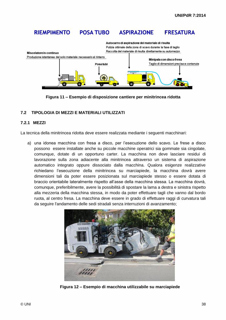
Narrow-mini-trenching operations require the following machinery and equipment:
a) a suitable trenching machine equipped with a disc cutter. Disc cutters can also be mounted
to small general purpose excavators, wheeled or tracked, provided that they are equipped
with suitable guarding. Spoil shall not be left by the machine alongside the trench, but
removed immediately by an automatic dust extraction system either built into or operating
independently of the machine. Where practical requirements dictate that a mini-trench needs
to be excavated on a footway, the machine shall be either compact enough to transit directly
on the footway itself, or if operating on the carriageway, equipped with an arm that can be
oriented parallel to the machine's own axis. In any event, the machine should have a
mechanism allowing displacement of the cutting tool to the right and to the left of centre, so
that the cut can be made on any given line between the wheels on either side. The machine
shall be able to follow a bending radius imposed by the path of the road bed without any
break in continuity of its forward progress;
Figure 12 – Example of machine for use on footways
UNI/PdR 7:2014
© UNI 38
Figura 11 – Esempio di disposizione cantiere per minitrincea ridotta
7.2 TIPOLOGIA DI MEZZI E MATERIALI UTILIZZATI
7.2.1 MEZZI
La tecnica della minitrincea ridotta deve essere realizzata mediante i seguenti macchinari:
a) una idonea macchina con fresa a disco, per l’esecuzione dello scavo. Le frese a disco
possono essere installate anche su piccole macchine operatrici sia gommate sia cingolate,
comunque, dotate di un opportuno carter. La macchina non deve lasciare residui di
lavorazione sulla zona adiacente alla minitrincea attraverso un sistema di aspirazione
automatico integrato oppure dissociato dalla macchina. Qualora esigenze realizzative
richiedano l’esecuzione della minitrincea su marciapiede, la macchina dovrà avere
dimensioni tali da poter essere posizionata sul marciapiede stesso o essere dotata di
braccio orientabile lateralmente rispetto all’asse della macchina stessa. La macchina dovrà,
comunque, preferibilmente, avere la possibilità di spostare la lama a destra e sinistra rispetto
alla mezzeria della macchina stessa, in modo da poter effettuare tagli che vanno dal bordo
ruota, al centro fresa. La macchina deve essere in grado di effettuare raggi di curvatura tali
da seguire l'andamento delle sedi stradali senza interruzioni di avanzamento;
Figura 12 – Esempio di macchina utilizzabile su marciapiede

UNI/PdR 7:2014
© UNI 39
b) a dust extraction machine, of capacity compatible with the scale of the projected excavation,
for removal of the spoil. The extractor shall operate simultaneously with the trencher. The
extraction unit can be coupled to the trenching machine by way of suitable ducts, or built into
the machine, so as to collect and eliminate the spoil directly from the point of excavation;
Figure 13 – Extent of site area during trenching and dust extraction
c) a mixer unit for the preparation of backfill material. The mixer unit shall allow the operator or
contractor to blend the components of the backfill material in the correct proportions, as
indicated by the manufacturer, and pour into the trench only the amount of material strictly
needed for the purpose of filling the void.
Figure 14 – Example of mini-trenching mixer and backfill unit

UNI/PdR 7:2014
© UNI 40
b) una macchina aspiratrice, con una capacità adeguata alle dimensioni dello scavo da
realizzare, per l’aspirazione del materiale di risulta. L'aspirazione deve avvenire
contestualmente all'apertura dello scavo. Il gruppo aspiratore può essere accoppiato alla
macchina con fresa a disco attraverso opportune tubazioni, o integrata alla stessa, in modo
da eliminare e raccogliere il materiale di risulta direttamente durante la fase di scavo;
Figura 13 – Ingombro dell’area di cantiere nella fase di scavo e di aspirazione
c) un gruppo miscelatore per la preparazione del materiale di riempimento. Il gruppo
miscelatore deve permettere di miscelare i componenti del materiale di riempimento nelle
loro corrette proporzioni, indicate dal produttore, e di versare all’interno dello scavo la
quantità di materiale strettamente necessaria al suo riempimento.
Figura 14 – Esempio di macchina miscelatrice e riempimento della minitrincea

UNI/PdR 7:2014
© UNI 41
7.2.2 BACKFILL MATERIALS
Narrow-mini-trenches shall be backfilled with a cement mortar of fluid consistency, containing high
strength cementitious binders, selected aggregates and special additives, which is poured into
place. The setting properties of the mortar shall be such that a vehicular carriageway can be
returned to normal use in ultra-quick time (within 2-4 hours following completion of the work).
Required specifications for quick setting mortar:
a) permissible application temperature: 5 °C to +35 °C;
b) workability retention: 15 minutes;
c) compressive strength (to UNI EN 12390-3):
after 2 hours: 10 N/mm2;
after 4 hours: 13 N/mm2;
after 24 hours: 16 N/mm2;
after 28 days: 30 N/mm2;
d) abrasion resistance (to UNI EN 13892-3 - Böhme test):
after 4 hours: Class A12;
e) thermal cycles without immersion in de-icing salts (to UNI EN 13687-3):
adhesion to concrete after 50 cycles: > 2 N/mm2.
The backfill, prepared to the specifications indicated above, shall guarantee the following quality-
related performance characteristics:
a) dimensional stability in use, with zero subsidence;
b) complete fill of excavated channel;
c) no cracks and/or crazing;
d) watertightness;
e) high abrasion resistance;
f) high flowability and self-placement without the aid of any manual or mechanical tamping.

UNI/PdR 7:2014
© UNI 42
7.2.2 MATERIALI DI RIEMPIMENTO
Il riempimento della minitrincea ridotta deve essere effettuato, mediante colatura entro la sede di
malta cementizia di consistenza fluida, a base di cementi ad alta resistenza, aggregati selezionati e
speciali additivi. Il materiale deve presentare caratteristiche di presa tali da permettere il rilascio di
una sede stradale carrabile e idonea all’utilizzo in tempi brevissimi (entro 2-4 ore dalla posa).
La malta, a rapido indurimento, dovrà avere le seguenti caratteristiche:
a) temperatura di applicazione permessa: da +5°C a +35°C;
b) tempo di lavorabilità: 15 minuti;
c) resistenza a compressione (secondo la UNI EN 12390-3):
dopo 2 ore: 10 N/mm2;
dopo 4 ore: 13 N/mm2;
dopo 24 ore: 16 N/mm2;
dopo 28 gg: 30 N/mm2;
d) resistenza all’abrasione (secondo la UNI EN 13892-3 - Abrasimetro Böhme):
dopo 4 ore: Classe A12;
e) cicli termici senza sali disgelanti (secondo la UNI EN 13687-3):
adesione al calcestruzzo dopo 50 cicli: > 2 N/mm2.
Il riempimento, realizzato secondo le caratteristiche sopra descritte, deve garantire le seguenti
prestazioni di qualità:
a) stabilità dimensionale in servizio senza registrare alcun cedimento;
b) completo riempimento dello scavo;
c) assenza di crepe e/o fessurazioni;
d) impermeabilità all’acqua;
e) elevata resistenza all’abrasione;
f) elevata fluidità e scorrevolezza senza l’ausilio di alcuna compattazione manuale o
meccanica.

UNI/PdR 7:2014
© UNI 43
7.3 NARROW-MINI-TRENCHING PROCEDURE
The route followed by the trench shall be linear as far as possible, with no sharp changes in
direction, and shall not exceed the minimum bending radius specified for the infrastructure and/or
underground utility laid internally of the channel.
7.3.1 EXCAVATION
The cut made with the disc shall be clean at the surface, causing absolutely no damage to the
wearing course along the areas adjoining the excavated section. The disc shall be housed internally
of a blade guard.
The surface roughness of the trench walls shall be sufficient to enable faultless adhesion with the
backfill material poured in subsequently.
7.3.2 CLEANING THE NARROW-MINI-TRENCH
The steps of excavating the channel and removing the spoil shall be performed simultaneously, so
as to speed up the process of cleaning the trench. These operations shall be carried out using
suitable dust suppression methods in order to ensure that the site is kept clean, while also
minimizing inconvenience to the public and pollution of the environment.
Following these first steps, the trench shall appear completely empty and the bottom devoid of
projecting stones; both the trench at the area immediately adjacent on either side shall be entirely
free of any debris that could adversely affect the mechanical properties of the backfill material.
Spoil shall be disposed of only at authorized landfill sites, proceeding in accordance with current
statutory regulations.
Figure 15 – Excavating and cleaning the narrow-mini-trench

UNI/PdR 7:2014
© UNI 44
7.3 MODALITÀ DI ESECUZIONE DELLA MINITRINCEA RIDOTTA
Il percorso della minitrincea ridotta deve essere il più possibile lineare, esente da bruschi
cambiamenti di direzione, e tale da rispettare i raggi minimi di curvatura specificati per le
infrastrutture e/o sottoservizi da posizionare all’interno dello scavo.
7.3.1 SCAVO
Il taglio effettuato con la fresa a disco deve risultare netto in superficie, evitando in modo assoluto di
danneggiare la pavimentazione stradale nei pressi della sezione di scavo. Il disco deve trovarsi
all'interno di un carter di protezione.
Le pareti dello scavo devono presentare una rugosità adeguata per permettere la perfetta adesione
con il materiale di riempimento da posare successivamente.
7.3.2 PULIZIA DELLA MINITRINCEA RIDOTTA
Le fasi di scavo e di aspirazione del materiale di risulta devono essere simultanee, in modo da
accelerare la pulizia della trincea. Tali operazioni devono essere eseguite prevedendo opportuni
metodi di abbattimento delle polveri al fine di mantenere la pulizia del cantiere e di contenere il
disagio della cittadinanza e l’inquinamento ambientale.
La sezione di scavo deve risultare al termine di questa attività completamente svuotata e il fondo
privo di sassi sporgenti; la trincea stessa e la zona immediatamente circostante devono risultare
totalmente ripulite dal materiale di risulta che potrebbe ridurre le caratteristiche meccaniche del
materiale di riempimento.
I materiali di risulta devono essere smaltiti presso idonea discarica autorizzata, in accordo con la
legislazione locale.
Figura 15 – Esecuzione dello scavo e pulizia della minitrincea ridotta

UNI/PdR 7:2014
© UNI 45
7.3.3 LAYING THE INFRASTRUCTURE
The infrastructure to be laid, typically pipes, or the underground utility, typically cables, are supplied
generally wound onto reels that shall be mounted to the machine or vehicle following the trencher
and dust extractor, in such a way that the pipes, tubes or cables can be decoiled continuously and
fed into the trench as the machine moves forward.
The configuration and positioning of these items in the trench shall be controlled in such a way that
the correct alignment is maintained along the entire length of the run, using appropriate fixing
systems if need be. To avoid the risk of foreign matter such as dust and water penetrating the pipes
and/or tubes during the various steps of the procedure, the ends should always be protected with
special caps or plugs.
Figure 16 – Example of fixing method for securing the infrastructure to the bottom of a
narrow-mini-trench
7.3.4 BACKFILL
With the infrastructure or underground utilities laid, the trench shall be backfilled with a high strength
and quick setting material as described in heading 7.2.2. The use of excavated spoil as backfill
material is prohibited. Besides securing the infrastructure in place, the backfill material shall also
guarantee mechanical protection.
The narrow-mini-trench is backfilled by pouring material into the channel, suitably cleaned and
prepared. The placement of the backfill in the trench shall be accomplished using a suitable pouring
system, guaranteed not to soil any part of the site and to ensure that the void is filled completely, up
to the level of the road surface, so that in backfilling the trench, the step of reinstating the surface of
the carriageway or footway is completed in one and the same operation.
Likewise when backfilling a narrow-mini-trench, the geometry of the infrastructure shall be
maintained, and there shall be no unwanted separation from the bottom of the channel. Any fixing
systems used to secure the infrastructure to the bottom of the channel shall allow optimum
penetration of the filling material, with no voids.

UNI/PdR 7:2014
© UNI 46
7.3.3 POSA DELL’INFRASTRUTTURA
L’infrastruttura da posare, tipicamente costituita da tubi, o il sottoservizio da posare, tipicamente
costituito da cavi, sono generalmente forniti su bobina che deve essere dislocata sulla macchina
che segue la fresa e l’aspiratore, in modo tale che i tubi, i minitubi o i cavi siano svolti e incanalati
nello scavo, mano a mano che la macchina procede.
La configurazione e la loro posizione all’interno dello scavo deve essere mantenuta per l’intera
lunghezza del tracciato, anche attraverso appositi sistemi di fissaggio. Onde evitare che corpi
estranei, come polvere e acqua, penetrino nei tubi e/o minitubi, in tutte le fasi operative, essi
dovranno essere sempre protetti alle estremità con appositi tappi.
Figura 16 – Esempio di fissaggio dell’infrastruttura al fondo della minitrincea ridotta
7.3.4 RIEMPIMENTO
Terminata la posa dell’infrastruttura o dei sottoservizi, la trincea deve essere riempita con un
materiale altamente resistente e a rapido indurimento come descritto a 7.2.2. È vietato l’utilizzo del
materiale di risulta per l’esecuzione dei rinterri. Il materiale di riempimento, oltre a bloccare
l’infrastruttura, deve garantire anche una protezione meccanica della stessa.
Il riempimento della minitrincea ridotta viene effettuato mediante colatura entro la sede
opportunamente predisposta e preparata. La posa del materiale di riempimento all’interno dello
scavo deve essere effettuata mediante idoneo sistema, da adottare per mantenere pulita l’area di
intervento e permettere il riempimento completo della minitrincea a filo della pavimentazione
stradale, realizzando, in tal modo, contestualmente, anche il ripristino della pavimentazione stradale
stessa.
Anche durante la fase di riempimento della minitrincea ridotta, deve essere garantita la geometria
dell’infrastruttura e non devono verificarsi innalzamenti indesiderati della stessa. Eventuali appositi
sistemi di fissaggio dell’infrastruttura al fondo dello scavo devono garantire una penetrazione
ottimale del materiale di riempimento.
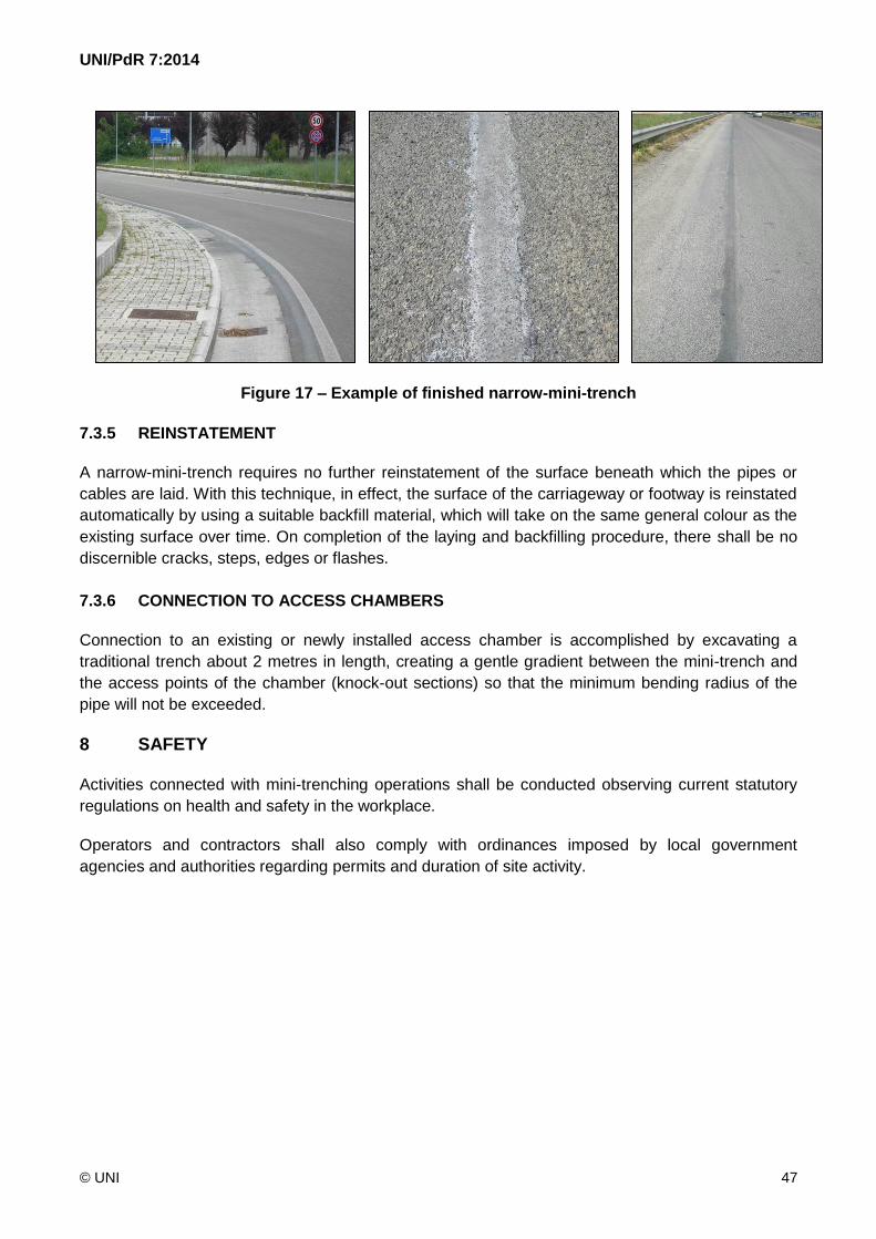
UNI/PdR 7:2014
© UNI 47
Figure 17 – Example of finished narrow-mini-trench
7.3.5 REINSTATEMENT
A narrow-mini-trench requires no further reinstatement of the surface beneath which the pipes or
cables are laid. With this technique, in effect, the surface of the carriageway or footway is reinstated
automatically by using a suitable backfill material, which will take on the same general colour as the
existing surface over time. On completion of the laying and backfilling procedure, there shall be no
discernible cracks, steps, edges or flashes.
7.3.6 CONNECTION TO ACCESS CHAMBERS
Connection to an existing or newly installed access chamber is accomplished by excavating a
traditional trench about 2 metres in length, creating a gentle gradient between the mini-trench and
the access points of the chamber (knock-out sections) so that the minimum bending radius of the
pipe will not be exceeded.
8 SAFETY
Activities connected with mini-trenching operations shall be conducted observing current statutory
regulations on health and safety in the workplace.
Operators and contractors shall also comply with ordinances imposed by local government
agencies and authorities regarding permits and duration of site activity.

UNI/PdR 7:2014
© UNI 48
Figura 17 – Esempi di minitrincea ridotta finita
7.3.5 RIPRISTINO
La minitrincea ridotta non richiede un ulteriore ripristino della pavimentazione superficiale su cui
viene realizzata la posa. La tecnica permette infatti un ripristino automatico della superficie, sia su
strada sia su marciapiede, mediante l’utilizzo di idoneo materiale di riempimento che assume nel
tempo colorazione simile a quella della pavimentazione esistente. Al termine delle attività di posa e
riempimento, non devono essere visibili crepe, gradini, bordi o sbavature.
7.3.6 INGRESSO NEI MANUFATTI
Il collegamento a un manufatto esistente o di nuova posa deve essere realizzato mediante uno
scavo di tipo tradizionale della lunghezza di circa 2 m, che consenta una discesa graduale di
raccordo tra la minitrincea e i punti di accesso al manufatto (setti a frattura) nel rispetto del minimo
raggio di curvatura del tubo.
8 SICUREZZA
Le attività inerenti la realizzazione delle minitrincee devono essere eseguite nel rispetto delle vigenti
normative nazionali in materia di sicurezza e salute sul lavoro.
Devono, altresì, essere rispettate le disposizioni impartite da Enti e Amministrazioni locali per
quanto riguarda la richiesta dei permessi e i periodi di apertura dei cantieri.
UNI/PdR 7:2014
© UNI 49
ANNEX A – MAIN LEGISLATIVE REFERENCES
APPENDICE A – PRINCIPALI RIFERIMENTI LEGISLATIVI
Decreto-Legge 23 dicembre 2013, n. 145
Interventi urgenti di avvio del piano "Destinazione Italia", per il contenimento delle tariffe elettriche e
del gas, per la riduzione dei premi RC-auto, per l'internazionalizzazione, lo sviluppo e la
digitalizzazione delle imprese, nonché misure per la realizzazione di opere pubbliche ed Expo
2015”, convertito con modificazioni dalla L. 21 febbraio 2014, n. 9 (G.U. 21 febbraio 2014, n. 43)
Decreto del Ministro dello Sviluppo Economico, di concerto col Ministro delle Infrastrutture e
dei Trasporti 1 ottobre 2013
Specifiche tecniche delle operazioni di scavo e ripristino per la posa di infrastrutture digitali nelle
infrastrutture stradali
Decreto-Legge 18 ottobre 2012, n. 179
Ulteriori misure urgenti per la crescita del Paese, come convertito dalla Legge 17 dicembre 2012, n.
221
Decreto-Legge 13 maggio 2011, n. 70
Decreto Sviluppo, coordinato con la Legge di conversione 12 luglio 2011, n. 106, (G.U. 12 luglio
2011, n. 160)
Decreto del Presidente della Repubblica 5 ottobre 2010, n. 207
Regolamento di esecuzione e attuazione del decreto legislativo 12 aprile 2006, n. 163, recante
“Codice dei contratti pubblici relativi a lavori, servizi e forniture in attuazione delle Direttive
2004/17/CE e 2004/18/CE ” (G.U. 10 dicembre 2010, n. 288 – S.O. n. 270 che prevede la categoria
OS 35: Interventi a basso impatto ambientale)
Decreto-Legge 25 marzo 2010, n. 40
Disposizioni urgenti tributarie e finanziarie in materia di contrasto alle frodi fiscali internazionali e
nazionali operate, tra l'altro, nella forma dei cosiddetti «caroselli» e «cartiere», di potenziamento e
razionalizzazione della riscossione tributaria anche in adeguamento alla normativa comunitaria, di
destinazione dei gettiti recuperati al finanziamento di un Fondo per incentivi e sostegno della
domanda in particolari settori, come convertito dalla Legge 22 maggio 2010, n. 73
Legge 18 giugno 2009, n. 69
Disposizioni per lo sviluppo economico, la semplificazione, la competitività nonché in materia di
processo civile
Decreto-Legge 25 giugno 2008, n. 112
Disposizioni urgenti per lo sviluppo economico, la semplificazione, la competitività, la stabilizzazione
della finanza pubblica e la perequazione tributaria, convertito con modificazioni dalla L. 6 agosto
2008, n. 133 (G.U. 21/08/2008, n.195 – S.O. n. 196)

UNI/PdR 7:2014
© UNI 50
Decreto Legislativo 9 aprile 2008, n. 81
Testo Coordinato con il Decreto Legislativo 3 agosto 2009, n°106 - Attuazione dell'articolo 1 della
Legge 3 agosto 2007, n. 123, in materia di tutela della salute e della sicurezza nei luoghi di lavoro
Decreto Legislativo 12 aprile 2006, n. 163
Codice dei contratti pubblici relativi a lavori, servizi e forniture in attuazione delle direttive
2004/17/CE e 2004/18/CE
Decreto Legislativo 3 aprile 2006, n. 152 (Norme in materia ambientale)
Attuazione della direttiva 2001/42/CE del Parlamento europeo e del Consiglio, del 27 giugno 2001,
concernente la valutazione degli effetti di determinati piani e programmi sull'ambiente
Decreto Legislativo 1 agosto 2003, n. 259
Codice delle comunicazioni elettroniche
Decreto Legislativo 12 giugno 2003, n. 233
Attuazione della direttiva 1999/92/CE relativa alle prescrizioni minime per il miglioramento della
tutela della sicurezza e della salute dei lavoratori esposti al rischio di atmosfere esplosive
Decreto Legislativo 30 aprile 1992, n. 285
Nuovo codice della strada - Decreto del Presidente della Repubblica 16 dicembre 1992, n. 495
Regolamento di esecuzione e di attuazione del nuovo codice della strada
Legge 6 dicembre 1971, n. 1083
Norme per la sicurezza dell'impiego del gas combustibile

UNI/PdR 7:2014
© UNI 51
BIBLIOGRAPHY
[1] UNI EN 206 Concrete - Specification, performance, production and conformity
[2] UNI EN 1338 Concrete paving blocks - Requirements and test methods
[3] UNI EN 1744-1 Tests for chemical properties of aggregates - Part 1: Chemical analysis
[4] UNI EN 12613 Plastics warning devices for underground cables and pipelines with visual
characteristics
[5] UNI EN 12620 Aggregates for concrete
[6] UNI EN 13043 Aggregates for bituminous mixtures and surface treatments for roads,
airfields and other trafficked areas
[7] UNI EN 13108-1 Bituminous mixtures - Material specifications - Part 1: Asphalt Concrete
[8] UNI EN 13108-2 Bituminous mixtures - Material specifications - Part 2: Asphalt Concrete
for very thin layers
[9] UNI EN 13108-3 Bituminous mixtures - Material specifications - Part 3: Soft Asphalt
[10] UNI EN 13108-5 Bituminous mixtures - Material specifications - Part 5: Stone Mastic
Asphalt
[11] UNI EN 13108-6 Bituminous mixtures - Material specifications - Part 6: Mastic Asphalt
[12] UNI EN 13108-7 Bituminous mixtures - Material specifications - Part 7: Porous Asphalt
[13] UNI EN 13108-20 Bituminous mixtures - Material specifications - Part 20: Type Testing
[14] UNI EN 13108-21 Bituminous mixtures - Material specifications - Part 21: Factory
Production Control
[15] UNI EN 13139 Aggregates for mortar
[16] UNI EN 13242 Aggregates for unbound and hydraulically bound materials for use in civil
engineering work and road construction
[17] UNI EN 13285 Unbound mixtures - Specifications
[18] UNI EN 13286-3 Unbound and hydraulically bound mixtures - Part 3: Test methods for
laboratory reference density and water content - Vibrocompression with controlled
parameters
[19] UNI EN 13286-41 Unbound and hydraulically bound mixtures - Part 41: Test method for the
determination of the compressive strength of hydraulically bound mixtures

UNI/PdR 7:2014
© UNI 52
BIBLIOGRAFIA
[1] UNI EN 206 Calcestruzzo - Specificazione, prestazione, produzione e conformità
[2] UNI EN 1338 Masselli di calcestruzzo per pavimentazione - Requisiti e metodi di prova
[3] UNI EN 1744-1 Prove per determinare le proprietà chimiche degli aggregati - Parte 1:
Analisi chimica
[4] UNI EN 12613 Dispositivi di avviso visuali di materia plastica per cavi e tubazioni interrati
[5] UNI EN 12620 Aggregati per calcestruzzo
[6] UNI EN 13043 Aggregati per miscele bituminose e trattamenti superficiali per strade,
aeroporti e altre aree soggette a traffico
[7] UNI EN 13108-1 Miscele bituminose - Specifiche del materiale - Parte 1: Conglomerato
bituminoso prodotto a caldo
[8] UNI EN 13108-2 Miscele bituminose - Specifiche del materiale - Parte 2: Conglomerato
bituminoso per strati molto sottili
[9] UNI EN 13108-3 Miscele bituminose - Specifiche del materiale - Parte 3: Conglomerato
con bitume molto tenero
[10] UNI EN 13108-5 Miscele bituminose - Specifiche del materiale - Parte 5: Conglomerato
bituminoso antisdrucciolo chiuso
[11] UNI EN 13108-6 Miscele bituminose - Specifiche del materiale - Parte 6: Asfalto colato
[12] UNI EN 13108-7 Miscele bituminose - Specifiche del materiale - Parte 7: Conglomerato
bituminoso ad elevato tenore di vuoti (drenante)
[13] UNI EN 13108-20 Miscele bituminose - Specifiche del materiale - Parte 20: Prove di tipo
[14] UNI EN 13108-21 Miscele bituminose - Specifiche del materiale - Parte 21: Controllo di
produzione in fabbrica
[15] UNI EN 13139 Aggregati per malta
[16] UNI EN 13242 Aggregati per materiali non legati e legati con leganti idraulici per l’impiego
in opera di ingegneria civile e nella costruzione di strade
[17] UNI EN 13285 Miscele non legate
[18] UNI EN 13286-3 Miscele non legate e legate con leganti idraulici - Parte 3: Metodo di prova
per la determinazione della massa volumica e del contenuto di acqua di riferimento di
laboratorio - Vibrocompressione a parametri controllati
[19] UNI EN 13286-41 Miscele non legate e legate con leganti idraulici - Parte 41: Metodo di
prova per la determinazione della compressione di miscele con leganti idraulici

UNI/PdR 7:2014
© UNI 53
[20] XP P98-333 Chaussées et dépendances - Tranchées de faibles dimensions
[21] ITU-T Recommendation L.48 Mini-trench installation technique
[22] ITU-T Recommendation L.49 Micro-trench installation technique
[23] ITU-T Recommendation L.83 Low impact trenching technique for FTTx networks
UNI/PdR 7:2014
© UNI 54
[20] XP P98-333 Chaussées et dépendances - Tranchées de faibles dimensions
[21] ITU-T Recommendation L.48 Mini-trench installation technique
[22] ITU-T Recommendation L.49 Micro-trench installation technique
[23] ITU-T Recommendation L.83 Low impact trenching technique for FTTx networks


Sede di MilanoVia Sannio, 2 - 20137 Milano
tel +39 02700241, Fax +39 0270024375, [email protected]
Sede di RomaVia del Collegio Capranica, 4 - 00186 Romatel +39 0669923074, Fax +39 066991604, [email protected]
Membro italiano ISO e CENwww.uni.com
www.youtube.com/normeUNIwww.twitter.com/normeUNI
www.twitter.com/formazioneUNI