Powertech - DKC · nuova normativa internazionale IEC 61439-6. Il condotto sbarre POWERTECH, nasce...
48
Powertech
Transcript of Powertech - DKC · nuova normativa internazionale IEC 61439-6. Il condotto sbarre POWERTECH, nasce...

Powertech


1
IndiceIntroduzione 2IntroductionCaratteristiche generali 3Technical dataConfigurazioni 5ConfigurationCodifica 6CodesElementi di percorso 9Trunking elementsUnità di derivazione 31Tap-off unitsSchede tecniche 38Data sheetIstruzioni di montaggio 40Instruction of assemblyCertificazioni 43Certifications
Indice
2
Introduzione
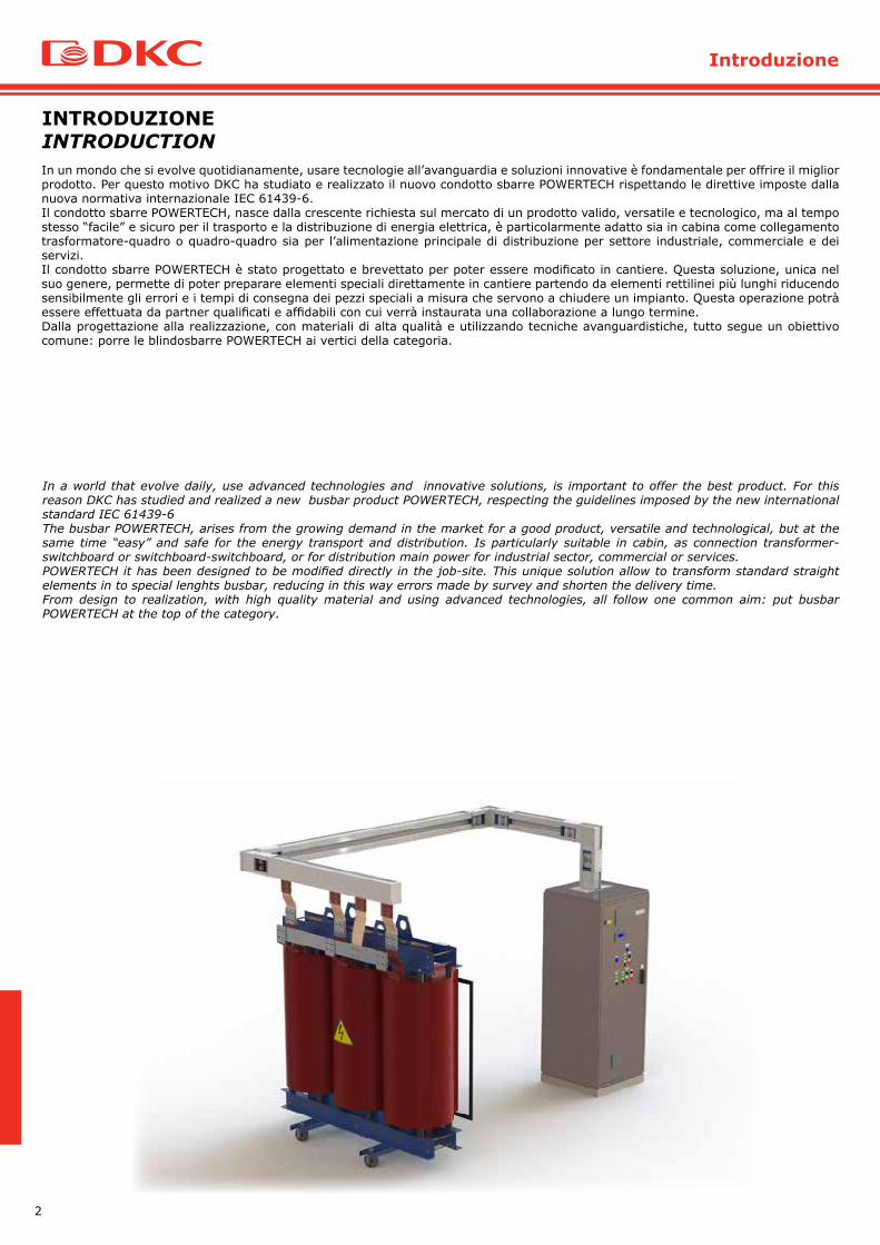
In un mondo che si evolve quotidianamente, usare tecnologie all’avanguardia e soluzioni innovative è fondamentale per offrire il miglior prodotto. Per questo motivo DKC ha studiato e realizzato il nuovo condotto sbarre POWERTECH rispettando le direttive imposte dalla nuova normativa internazionale IEC 61439-6.Il condotto sbarre POWERTECH, nasce dalla crescente richiesta sul mercato di un prodotto valido, versatile e tecnologico, ma al tempo stesso “facile” e sicuro per il trasporto e la distribuzione di energia elettrica, è particolarmente adatto sia in cabina come collegamento trasformatore-quadro o quadro-quadro sia per l’alimentazione principale di distribuzione per settore industriale, commerciale e dei servizi.Il condotto sbarre POWERTECH è stato progettato e brevettato per poter essere modificato in cantiere. Questa soluzione, unica nel suo genere, permette di poter preparare elementi speciali direttamente in cantiere partendo da elementi rettilinei più lunghi riducendo sensibilmente gli errori e i tempi di consegna dei pezzi speciali a misura che servono a chiudere un impianto. Questa operazione potrà essere effettuata da partner qualificati e affidabili con cui verrà instaurata una collaborazione a lungo termine. Dalla progettazione alla realizzazione, con materiali di alta qualità e utilizzando tecniche avanguardistiche, tutto segue un obiettivo comune: porre le blindosbarre POWERTECH ai vertici della categoria.
INTRODUZIONE INTRODUCTION
In a world that evolve daily, use advanced technologies and innovative solutions, is important to offer the best product. For this reason DKC has studied and realized a new busbar product POWERTECH, respecting the guidelines imposed by the new international standard IEC 61439-6The busbar POWERTECH, arises from the growing demand in the market for a good product, versatile and technological, but at the same time “easy” and safe for the energy transport and distribution. Is particularly suitable in cabin, as connection transformer-switchboard or switchboard-switchboard, or for distribution main power for industrial sector, commercial or services.POWERTECH it has been designed to be modified directly in the job-site. This unique solution allow to transform standard straight elements in to special lenghts busbar, reducing in this way errors made by survey and shorten the delivery time.From design to realization, with high quality material and using advanced technologies, all follow one common aim: put busbar POWERTECH at the top of the category.
3
Caratteristiche tecniche
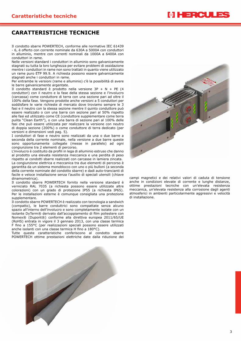
Il condotto sbarre POWERTECH, conforme alle normative IEC 61439 - 6, è offerto con corrente nominale da 630A a 5000A con conduttori in alluminio, mentre con correnti nominali da 1000A a 6400A con conduttori in rame.Nelle versioni standard i conduttori in alluminio sono galvanicamente stagnati su tutta la loro lunghezza per evitare problemi di ossidazione mentre i conduttori in rame non sono trattati in quanto viene utilizzato un rame puro ETP 99.9. A richiesta possono essere galvanicamente stagnati anche i conduttori in rame.Per entrambe le versioni (rame e alluminio) c’è la possibilità di avere le barre galvanicamente argentate.Il condotto standard è prodotto nella versione 3P + N + PE (4 conduttori) con il neutro e la fase della stessa sezione e l’involucro (carcassa) come conduttore di terra con una sezione pari ad oltre il 100% della fase. Vengono prodotte anche versioni a 5 conduttori per soddisfare le varie richieste di mercato dove troviamo sempre le 3 fasi e il neutro con la stessa sezione mentre il quinto conduttore può essere realizzato o con una barra con sezione pari al 50% rispetto alle fasi ed utilizzato come CE (conduttore supplementare come terra pulita “Clean Earth”), o con una barra di sezione pari al 100% delle fasi che può essere utilizzata per realizzare la versione con neutro di doppia sezione (200%) o come conduttore di terra dedicato (per versioni e dimensioni vedi pag. 5). I conduttori di fase e neutro sono realizzati da una o due barre a seconda della corrente nominale, nella versione a due barre queste sono opportunamente collegate (messe in parallelo) ad ogni congiunzione tra 2 elementi di percorso.L’involucro è costituito da profili in lega di alluminio estruso che danno al prodotto una elevata resistenza meccanica e una perdita di peso rispetto ai condotti sbarre realizzati con carcasse in lamiera zincata. La congiunzione elettrica e meccanica tra due elementi di percorso è garantita da un sistema monoblocco con uno o più bulloni (a seconda della corrente nominale del condotto sbarre) e dadi auto-trancianti di facile e veloce installazione senza l’ausilio di speciali utensili (chiave dinamometrica).Il condotto sbarre POWERTECH fornito nella versione standard è verniciato RAL 7035 (a richiesta possono essere utilizzate altre colorazioni) con un grado di protezione IP55 (a richiesta IP65). Per le installazioni esterne è comunque consigliata una protezione supplementare.Il condotto sbarre POWERTECH è realizzato con tecnologia a sandwich (compatto), le barre conduttrici sono compattate senza alcuno spazio all’interno dell’involucro e sono completamente isolate con un isolante DyTerm® derivato dall’accoppiamento di film poliestere con Nomex® (Dupont®) conforme alla direttiva europea 2011/65/UE (RoHS) entrata in vigore il 3 gennaio 2013, con una classe termica F fino a 155°C (per realizzazioni speciali possono essere utilizzati anche isolanti con una classe termica H fino a 180°C).Tutte queste caratteristiche conferiscono al condotto sbarre POWERTECH ottime prestazioni elettriche date dalla riduzione dei
campi magnetici e dei relativi valori di caduta di tensione anche in condizioni elevate di corrente e lunghe distanze, ottime prestazioni tecniche con un’elevata resistenza meccanica, un’elevata resistenza alla corrosione dagli agenti atmosferici in ambienti particolarmente aggressivi e velocità di installazione.
CARATTERISTICHE TECNICHE
4
Technical data
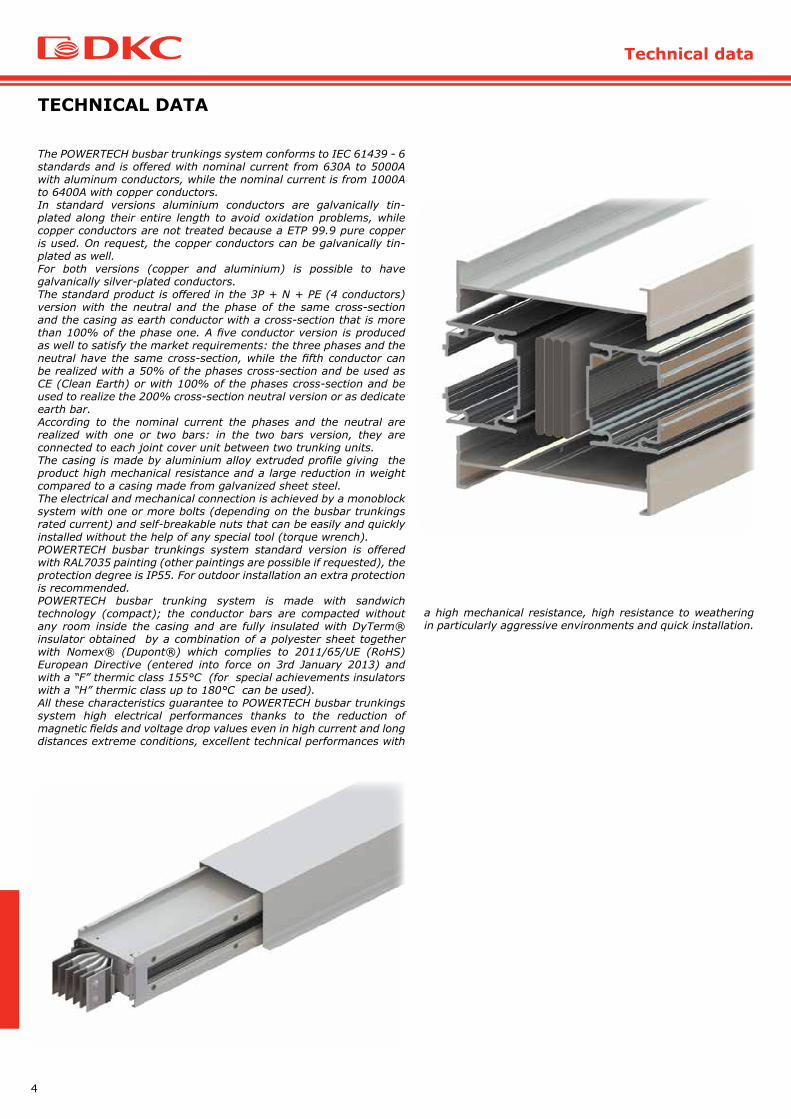
The POWERTECH busbar trunkings system conforms to IEC 61439 - 6 standards and is offered with nominal current from 630A to 5000A with aluminum conductors, while the nominal current is from 1000A to 6400A with copper conductors.In standard versions aluminium conductors are galvanically tin-plated along their entire length to avoid oxidation problems, while copper conductors are not treated because a ETP 99.9 pure copper is used. On request, the copper conductors can be galvanically tin-plated as well.For both versions (copper and aluminium) is possible to have galvanically silver-plated conductors.The standard product is offered in the 3P + N + PE (4 conductors) version with the neutral and the phase of the same cross-section and the casing as earth conductor with a cross-section that is more than 100% of the phase one. A five conductor version is produced as well to satisfy the market requirements: the three phases and the neutral have the same cross-section, while the fifth conductor can be realized with a 50% of the phases cross-section and be used as CE (Clean Earth) or with 100% of the phases cross-section and be used to realize the 200% cross-section neutral version or as dedicate earth bar. According to the nominal current the phases and the neutral are realized with one or two bars: in the two bars version, they are connected to each joint cover unit between two trunking units.The casing is made by aluminium alloy extruded profile giving the product high mechanical resistance and a large reduction in weight compared to a casing made from galvanized sheet steel. The electrical and mechanical connection is achieved by a monoblock system with one or more bolts (depending on the busbar trunkings rated current) and self-breakable nuts that can be easily and quickly installed without the help of any special tool (torque wrench).POWERTECH busbar trunkings system standard version is offered with RAL7035 painting (other paintings are possible if requested), the protection degree is IP55. For outdoor installation an extra protection is recommended.POWERTECH busbar trunking system is made with sandwich technology (compact); the conductor bars are compacted without any room inside the casing and are fully insulated with DyTerm® insulator obtained by a combination of a polyester sheet together with Nomex® (Dupont®) which complies to 2011/65/UE (RoHS) European Directive (entered into force on 3rd January 2013) and with a “F” thermic class 155°C (for special achievements insulators with a “H” thermic class up to 180°C can be used). All these characteristics guarantee to POWERTECH busbar trunkings system high electrical performances thanks to the reduction of magnetic fields and voltage drop values even in high current and long distances extreme conditions, excellent technical performances with
a high mechanical resistance, high resistance to weathering in particularly aggressive environments and quick installation.
TECHNICAL DATA
5
Caratteristiche tecniche
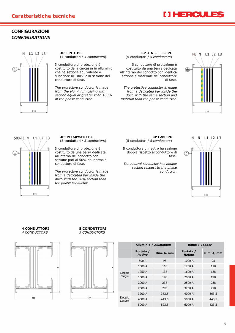
3P + N + PE (4 conduttori / 4 conductors)
Il conduttore di protezione è costituito dalla carcassa in alluminio che ha sezione equivalente o superiore al 100% alla sezione del conduttore di fase.
The protective conductor is made from the aluminium casing with section equal or greater than 100% of the phase conductor.
3P + N + FE + PE (5 conduttori / 5 conductors)
Il conduttore di protezione è costituito da una barra dedicata
all’interno del condotto con identica sezione e materiale del conduttore
di fase.
The protective conductor is made from a dedicated bar inside the
duct, with the same section and material than the phase conductor.
3P+N+50%FE+PE (5 conduttori / 5 conductors)
Il conduttore di protezione è costituito da una barra dedicata all’interno del condotto con sezione pari al 50% del normale conduttore di fase.
The protective conductor is made from a dedicated bar inside the duct, with the 50% section than the phase conductor.
3P+2N+PE (5 conduttori / 5 conductors)
Il conduttore di neutro ha sezione doppia rispetto al conduttore di
fase.
The neutral conductor has double section respect to the phase
conductor.
CONFIGURAZIONICONFIGURATIONS
4 CONDUTTORI4 CONDUCTORS
5 CONDUTTORI5 CONDUCTORS
Alluminio / Aluminium Rame / Copper
Portata / Rating Dim. A, mm Portata /
Rating Dim. A, mm
SingoloSingle
800 A 98 1000 A 98
1000 A 118 1250 A 118
1250 A 138 1600 A 138
1600 A 198 2000 A 198
2000 A 238 2500 A 238
2500 A 278 3200 A 278
DoppioDouble
3200 A 363,5 4000 A 363,5
4000 A 443,5 5000 A 443,5
5000 A 523,5 6000 A 523,5
6
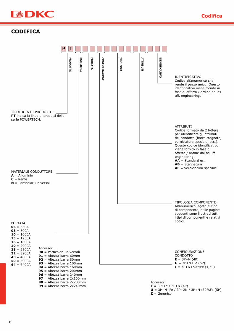
Codifica
TIPOLOGIA DI PRODOTTOPT indica la linea di prodotti della serie POWERTECH.
MATERIALE CONDUTTOREA = AlluminioC = RameN = Particolari universali
IDEN
TIFICATIVO
PROD
OTTO
MATERIALE
PORTATA
CON
FIGU
RAZION
E
TIPOLO
GIA
ATTRIBUTI
TP
PORTATA06 = 630A08 = 800A10 = 1000A13 = 1250A16 = 1600A20 = 2000A25 = 2500A32 = 3200A40 = 4000A50 = 5000A64 = 6400A
CONFIGURAZIONE CONDOTTOE = 3P+N (4P)G = 3P+N+Fe (5P)I = 3P+N+50%Fe (4,5P)
Accessori90 = Particolari universali91 = Altezza barra 60mm92 = Altezza barra 80mm93 = Altezza barra 100mm94 = Altezza barra 160mm95 = Altezza barra 200mm96 = Altezza barra 240mm97 = Altezza barra 2x160mm98 = Altezza barra 2x200mm99 = Altezza barra 2x240mm
AccessoriT = 3P+Fe / 3P+N (4P)U = 3P+N+Fe / 3P+2N / 3P+N+50%Fe (5P)Z = Generico
IDENTIFICATIVOCodice alfanumerico che rende il pezzo unico. Questo identificativo viene fornito in fase di offerta / ordine dal ns uff. engineering.
ATTRIBUTICodice formato da 2 lettere per identificare gli attributi del condotto (barre stagnate, verniciatura speciale, ecc.).Questo codice identificativo viene fornito in fase di offerta / ordine dal ns uff. engineering.AA = Standard es.AB = StagnaturaAF = Verniciatura speciale
TIPOLOGIA COMPONENTEAlfanumerico legato al tipo di componente, nelle pagine seguenti sono illustrati tutti i tipi di componenti e relativi codici.
CODIFICA

7
Codes
PRODUCT TYPEPT indicates the product line of the series POWERTECH.
CONDUCTOR MATERIALA = AluminiumC = CopperN = Universal items
TP
IDEN
TIFICATION
PROD
UCT TYPE
RATING
FEATURES
TYPE OF CO
MPO
NEN
T
PROD
UCT CO
NFIG
URATIO
N
CON
DU
CTOR M
ATERIAL
RATING06 = 630A08 = 800A10 = 1000A13 = 1250A16 = 1600A20 = 2000A25 = 2500A32 = 3200A40 = 4000A50 = 5000A64 = 6400A
PRODUCT CONFIGURATIONE = 3P+N (4P)G = 3P+N+Fe (5P)I = 3P+N+50%Fe (4,5P)
Accessories90 = Universal items91 = Bar width 60mm92 = Bar width 80mm93 = Bar width 100mm94 = Bar width 160mm95 = Bar width 200mm96 = Bar width 240mm97 = Bar width 2x160mm98 = Bar width 2x200mm99 = Bar width 2x240mm
AccessoriesT = 3P+Fe / 3P+N (4P)U = 3P+N+Fe / 3P+2N / 3P+N+50%Fe (5P)Z = Generic
IDENTIFICATION Alphanumeric code makes it unique the item. This code isassigned during the offer/order phase by our engineering dept.
FEATURESConsists in two letters to identify the features of the product (bars tin-plated, special painting, etc). This code is assigned during the offer/order phase by our engineering dept.AA = Standard example:AB = Tin platedAF = Special painting
TYPE OF COMPONENTAlphanumeric code connected to the component. In the following pages we describe all kinds of components and related codes.
CODES

8
Note

9
Trunking elements
ELEMENTO RETTILINEOSTRAIGHT ELEMENT
Elemento rettilineo di trasporto, può essere utilizzato in tratti orizzontali o verticali.Feeder Straight trunking element, can be used in vertical or horizontal runs.
SEF1 = Elemento rettilineo std. 3000 Straight Element std 3000 mmSEF2 = Elemento rettilineo spec. < 3000 Special Straight Element < 3000 mm
TP
TIPOLO
GIA
ELEMENTI DI PERCORSOTRUNKING ELEMENTS
10
Elementi di percorso
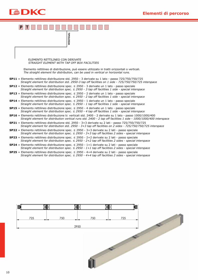
ELEMENTO RETTILINEO CON DERIVATESTRAIGHT ELEMENT WITH TAP OFF BOX FACILITIES
Elemento rettilineo di distribuzione, può essere utilizzato in tratti orizzontali o verticali.The straight element for distribution, can be used in vertical or horizontal runs.
SP11 = Elemento rettilineo distribuzione std. 2950 - 3 derivate su 1 lato - passo 725/750/750/725 Straight element for distribution std. 2950-3 tap off facilities on 1 side - 725/750/750/725 interspaceSP12 = Elemento rettilineo distribuzione spec. ≤ 2950 - 3 derivate un 1 lato - passo speciale Straight element for distribution spec. ≤ 2950 - 3 tap off facilities 1 side - special interspaceSP13 = Elemento rettilineo distribuzione spec. ≤ 2950 - 2 derivate un 1 lato - passo speciale Straight element for distribution spec. ≤ 2950 - 2 tap off facilities 1 side - special interspaceSP14 = Elemento rettilineo distribuzione spec. ≤ 2950 - 1 derivate un 1 lato - passo speciale Straight element for distribution spec. ≤ 2950 - 1 tap off facilities 1 side - special interspaceSP15 = Elemento rettilineo distribuzione spec. ≤ 2950 - 4 derivate un 1 lato - passo speciale Straight element for distribution spec. ≤ 2950 - 4 tap off facilities 1 side - special interspaceSP16 = Elemento rettilineo distribuzione tr. verticali std. 2400 - 2 derivate su 1 lato - passo 1000/1000/400 Straight element for distribution vertical runs std. 2400 - 2 tap off facilities 1 side - 1000/1000/400 interspaceSP21 = Elemento rettilineo distribuzione std. 2950 - 3+3 derivate su 2 lati - passo 725/750/750/725 Straight element for distribution std. 2950 - 3+3 tap off facilities on 2 sides - 725/750/750/725 interspaceSP22 = Elemento rettilineo distribuzione spec. ≤ 2950 - 3+3 derivate su 2 lati - passo speciale Straight element for distribution spec. ≤ 2950 - 3+3 tap off facilities 2 sides - special interspaceSP23 = Elemento rettilineo distribuzione spec. ≤ 2950 - 2+2 derivate su 2 lati - passo speciale Straight element for distribution spec. ≤ 2950 - 2+2 tap off facilities 2 sides - special interspaceSP24 = Elemento rettilineo distribuzione spec. ≤ 2950 - 1+1 derivate su 2 lati - passo speciale Straight element for distribution spec. ≤ 2950 - 1+1 tap off facilities 2 sides - special interspaceSP25 = Elemento rettilineo distribuzione spec. ≤ 2950 - 4+4 derivate su 2 lati - passo speciale Straight element for distribution spec. ≤ 2950 - 4+4 tap off facilities 2 sides - special interspace
TP
TIPOLO
GIA

11
Trunking elements
ANGOLO ORIZZONTALE HORIZONTAL ELBOW
Elemento che permette di effettuare una curva in senso orizzontale (vedi immagine).Element that allows to make a change of direction in horizontally (see image).
HEL1 = Angolo orizzontale tipo 1 standard Horizontal elbow type 1 standardHEL2 = Angolo orizzontale tipo 2 standard Horizontal elbow type 2 standardHEL3 = Angolo orizzontale tipo 1 speciale Horizontal elbow type 1 specialHEL4 = Angolo orizzontale tipo 2 speciale Horizontal elbow type 2 special
TP
TIPOLO
GIA
N
N
TIPO 1TYPE 1
TIPO 2TYPE 2
Dimensioni standard/Standard dimensions
A B
B60 250 250
B80 250 250
B100 250 250
B160 250 250
B200 250 250
B240 250 250
2B160 250 250
2B200 250 250
2B240 250 250
Dimensioni massime/Maximum dimensions
A B
B60 749 749
B80 749 749
B100 749 749
B160 749 749
B200 749 749
B240 749 749
2B160 749 749
2B200 749 749
2B240 749 749
12
Elementi di percorso
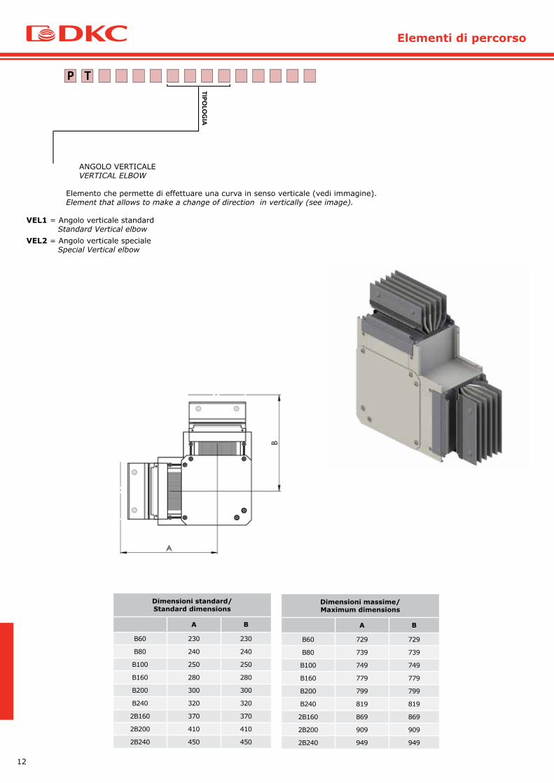
ANGOLO VERTICALE VERTICAL ELBOW
Elemento che permette di effettuare una curva in senso verticale (vedi immagine).Element that allows to make a change of direction in vertically (see image).
VEL1 = Angolo verticale standard Standard Vertical elbowVEL2 = Angolo verticale speciale Special Vertical elbow
TP
TIPOLO
GIA
Dimensioni standard/Standard dimensions
A B
B60 230 230
B80 240 240
B100 250 250
B160 280 280
B200 300 300
B240 320 320
2B160 370 370
2B200 410 410
2B240 450 450
Dimensioni massime/Maximum dimensions
A B
B60 729 729
B80 739 739
B100 749 749
B160 779 779
B200 799 799
B240 819 819
2B160 869 869
2B200 909 909
2B240 949 949
13
Trunking elements
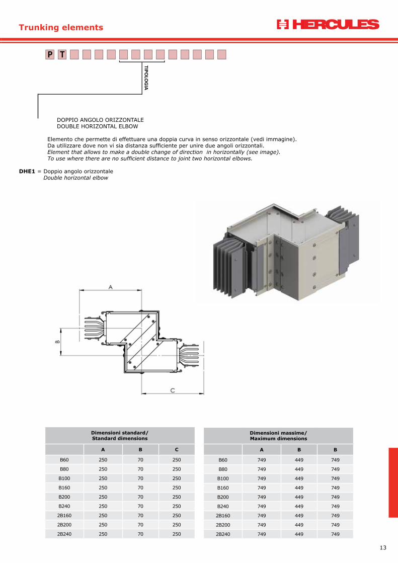
DOPPIO ANGOLO ORIZZONTALE DOUBLE HORIZONTAL ELBOW
Elemento che permette di effettuare una doppia curva in senso orizzontale (vedi immagine). Da utilizzare dove non vi sia distanza sufficiente per unire due angoli orizzontali. Element that allows to make a double change of direction in horizontally (see image).To use where there are no sufficient distance to joint two horizontal elbows.
DHE1 = Doppio angolo orizzontale Double horizontal elbow
TP
TIPOLO
GIA
Dimensioni standard/Standard dimensions
A B C
B60 250 70 250
B80 250 70 250
B100 250 70 250
B160 250 70 250
B200 250 70 250
B240 250 70 250
2B160 250 70 250
2B200 250 70 250
2B240 250 70 250
Dimensioni massime/Maximum dimensions
A B B
B60 749 449 749
B80 749 449 749
B100 749 449 749
B160 749 449 749
B200 749 449 749
B240 749 449 749
2B160 749 449 749
2B200 749 449 749
2B240 749 449 749

14
Elementi di percorso
DOPPIO ANGOLO VERTICALE DOUBLE VERTICAL ELBOW
Elemento che permette di effettuare una doppia curva in senso verticale (vedi immagine). Da utilizzare dove non vi sia distanza sufficiente per unire due angoli verticali.Element that allows to make a double change of direction in vertically (see image).To use where there are no sufficient distance to joint two vertical elbows.
DVE1 = Doppio angolo verticale tipo 1 Double vertical elbow type 1DVE2 = Doppio angolo verticale tipo 2 Double vertical elbow type 2
TP
TIPOLO
GIA
Dimensioni standard/Standard dimensions
A B C
B60 230 80 230
B80 240 80 240
B100 250 80 250
B160 280 80 280
B200 300 80 300
B240 320 80 320
2B160 370 80 370
2B200 410 80 410
2B240 450 80 450
Dimensioni massime/Maximum dimensions
A B B
B60 729 459 729
B80 739 479 739
B100 749 499 749
B160 779 559 779
B200 799 599 799
B240 819 639 819
2B160 869 739 869
2B200 909 819 909
2B240 949 899 949
15
Trunking elements
DOPPIO ANGOLO VERTICALE DOUBLE VERTICAL ELBOW
Elemento che permette di effettuare una doppia curva in senso verticale (vedi immagine). Da utilizzare dove non vi sia distanza sufficiente per unire due angoli verticali.Element that allows to make a double change of direction in vertically (see image).To use where there are no sufficient distance to joint two vertical elbows.
DVE1 = Doppio angolo verticale tipo 1 Double vertical elbow type 1DVE2 = Doppio angolo verticale tipo 2 Double vertical elbow type 2
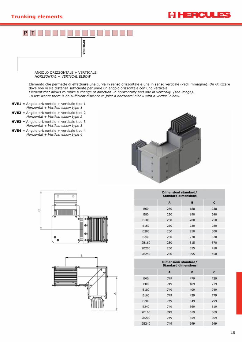
ANGOLO ORIZZONTALE + VERTICALEHORIZONTAL + VERTICAL ELBOW
Elemento che permette di effettuare una curva in senso orizzontale e una in senso verticale (vedi immagine). Da utilizzare dove non vi sia distanza sufficiente per unire un angolo orizzontale con uno verticale. Element that allows to make a change of direction in horizontally and one in vertically (see image). To use where there is no sufficient distance to joint a horizontal elbow with a vertical elbow.
HVE1 = Angolo orizzontale + verticale tipo 1 Horizontal + Vertical elbow type 1HVE2 = Angolo orizzontale + verticale tipo 2 Horizontal + Vertical elbow type 2HVE3 = Angolo orizzontale + verticale tipo 3 Horizontal + Vertical elbow type 3HVE4 = Angolo orizzontale + verticale tipo 4 Horizontal + Vertical elbow type 4
TP
TIPOLO
GIA
Dimensioni standard/Standard dimensions
A B C
B60 250 180 230
B80 250 190 240
B100 250 200 250
B160 250 230 280
B200 250 250 300
B240 250 270 320
2B160 250 315 370
2B200 250 355 410
2B240 250 395 450
Dimensioni standard/Standard dimensions
A B C
B60 749 479 729
B80 749 489 739
B100 749 499 749
B160 749 429 779
B200 749 549 799
B240 749 569 819
2B160 749 619 869
2B200 749 659 909
2B240 749 699 949
16
Elementi di percorso
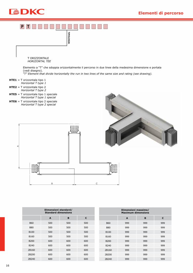
T ORIZZONTALE HORIZONTAL TEE
Elemento a “T” che sdoppia orizzontalmente il percorso in due linee della medesima dimensione e portata (vedi disegno).“T” Element that divide horizontally the run in two lines of the same size and rating (see drawing).
HTE1 = T orizzontale tipo 1 Horizontal T type 1HTE2 = T orizzontale tipo 2 Horizontal T type 2HTE5 = T orizzontale tipo 1 speciale Horizontal T type 1 specialHTE6 = T orizzontale tipo 2 speciale Horizontal T type 2 special
TP
TIPOLO
GIA
Dimensioni standard/Standard dimensions
A B C
B60 500 500 500
B80 500 500 500
B100 500 500 500
B160 500 500 500
B200 600 600 600
B240 600 600 600
2B160 600 600 600
2B200 600 600 600
2B240 600 600 600
Dimensioni massime/Maximum dimensions
A B C
B60 999 999 999
B80 999 999 999
B100 999 999 999
B160 999 999 999
B200 999 999 999
B240 999 999 999
2B160 999 999 999
2B200 999 999 999
2B240 999 999 999

17
Trunking elements
TP
TIPOLO
GIA
T VERTICALE VERTICAL TEE
Elemento a “T” che sdoppia verticalmente il percorso in due linee della medesima dimensione e portata (vedi disegno).“T” Element that divide vertically the run in two lines of the same size and rating (see drawing).
VTE1 = T verticale Vertical TVTE2 = T verticale speciale Vertical T special
(*) = Le dimensioni devono essere verificare dal nostro uff. Engineering.Dimensions to be checked by our Engineering department.
Dimensioni standard/Standard dimensions
A B C
B60 230 230 230
B80 240 240 240
B100 250 250 250
B160 280 280 280
B200 300 300 300
B240 320 320 320
2B160 370 370 370
2B200 410 410 410
2B240 450 450 450
Dimensioni massime/Maximum dimensions
A B B
B60 729 729 729
B80 739 739 739
B100 749 749 749
B160 779 779 779
B200 799 799 799
B240 819 819 819
2B160 869 869 869
2B200 909 909 909
2B240 949 949 949

18
Elementi di percorso
TERMINALE QUADRO / TRASFORMATORETERMINAL UNIT
Terminale di connessione a quadro o trasformatore.Terminal connection to switchboard or transformer.
TST1 = Terminale quadro / trasformatore standard Terminal switchboard / transformer standardTST2 = Terminale quadro / trasformatore speciale Terminal switchboard / transformer special
TP
TIPOLO
GIA
Dimensioni standard/Standard dimensions
A H
B60 200 200
B80 200 200
B100 200 200
B160 200 200
B200 200 200
B240 200 200
2B160 200 200
2B200 200 200
2B240 200 200
Dimensioni massime/Maximum dimensions
A H
B60 699 200
B80 699 200
B100 699 200
B160 699 200
B200 699 200
B240 699 200
2B160 699 200
2B200 699 200
2B240 699 200
19
Trunking elements
20
Elementi di percorso
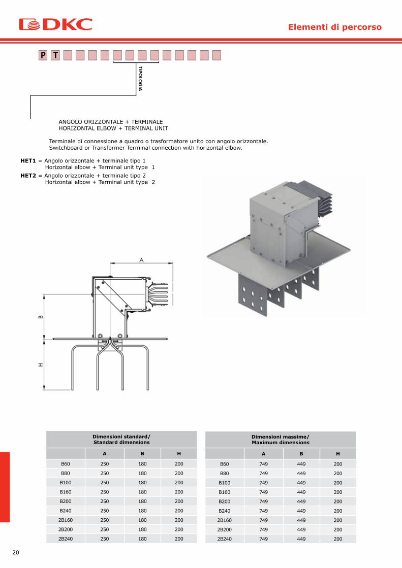
ANGOLO ORIZZONTALE + TERMINALEHORIZONTAL ELBOW + TERMINAL UNIT
Terminale di connessione a quadro o trasformatore unito con angolo orizzontale.Switchboard or Transformer Terminal connection with horizontal elbow.
HET1 = Angolo orizzontale + terminale tipo 1 Horizontal elbow + Terminal unit type 1HET2 = Angolo orizzontale + terminale tipo 2 Horizontal elbow + Terminal unit type 2
TP
TIPOLO
GIA
Dimensioni standard/Standard dimensions
A B H
B60 250 180 200
B80 250 180 200
B100 250 180 200
B160 250 180 200
B200 250 180 200
B240 250 180 200
2B160 250 180 200
2B200 250 180 200
2B240 250 180 200
Dimensioni massime/Maximum dimensions
A B H
B60 749 449 200
B80 749 449 200
B100 749 449 200
B160 749 449 200
B200 749 449 200
B240 749 449 200
2B160 749 449 200
2B200 749 449 200
2B240 749 449 200
21
Trunking elements
ANGOLO ORIZZONTALE + TERMINALEHORIZONTAL ELBOW + TERMINAL UNIT
Terminale di connessione a quadro o trasformatore unito con angolo orizzontale.Switchboard or Transformer Terminal connection with horizontal elbow.
HET1 = Angolo orizzontale + terminale tipo 1 Horizontal elbow + Terminal unit type 1HET2 = Angolo orizzontale + terminale tipo 2 Horizontal elbow + Terminal unit type 2
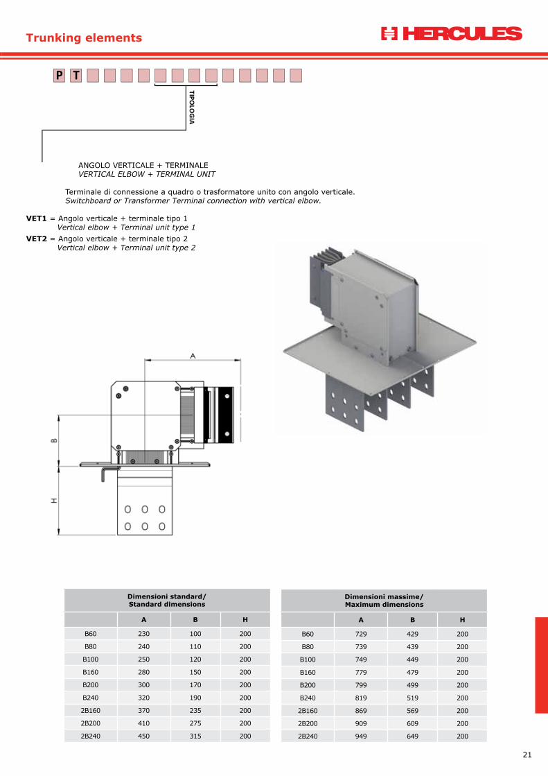
ANGOLO VERTICALE + TERMINALE VERTICAL ELBOW + TERMINAL UNIT
Terminale di connessione a quadro o trasformatore unito con angolo verticale. Switchboard or Transformer Terminal connection with vertical elbow.
VET1 = Angolo verticale + terminale tipo 1 Vertical elbow + Terminal unit type 1VET2 = Angolo verticale + terminale tipo 2 Vertical elbow + Terminal unit type 2
TP
TIPOLO
GIA
Dimensioni standard/Standard dimensions
A B H
B60 230 100 200
B80 240 110 200
B100 250 120 200
B160 280 150 200
B200 300 170 200
B240 320 190 200
2B160 370 235 200
2B200 410 275 200
2B240 450 315 200
Dimensioni massime/Maximum dimensions
A B H
B60 729 429 200
B80 739 439 200
B100 749 449 200
B160 779 479 200
B200 799 499 200
B240 819 519 200
2B160 869 569 200
2B200 909 609 200
2B240 949 649 200
22
Elementi di percorso
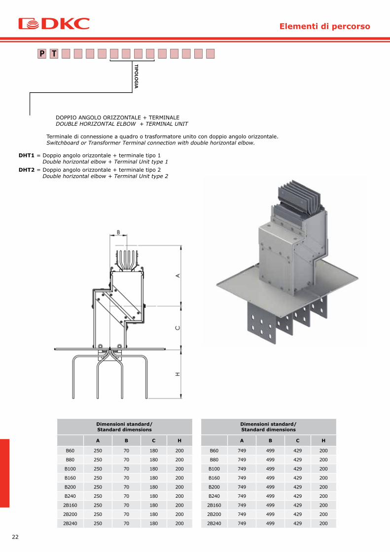
DOPPIO ANGOLO ORIZZONTALE + TERMINALE DOUBLE HORIZONTAL ELBOW + TERMINAL UNIT
Terminale di connessione a quadro o trasformatore unito con doppio angolo orizzontale. Switchboard or Transformer Terminal connection with double horizontal elbow.
DHT1 = Doppio angolo orizzontale + terminale tipo 1 Double horizontal elbow + Terminal Unit type 1DHT2 = Doppio angolo orizzontale + terminale tipo 2 Double horizontal elbow + Terminal Unit type 2
TP
TIPOLO
GIA
Dimensioni standard/Standard dimensions
A B C H
B60 250 70 180 200
B80 250 70 180 200
B100 250 70 180 200
B160 250 70 180 200
B200 250 70 180 200
B240 250 70 180 200
2B160 250 70 180 200
2B200 250 70 180 200
2B240 250 70 180 200
Dimensioni standard/Standard dimensions
A B C H
B60 749 499 429 200
B80 749 499 429 200
B100 749 499 429 200
B160 749 499 429 200
B200 749 499 429 200
B240 749 499 429 200
2B160 749 499 429 200
2B200 749 499 429 200
2B240 749 499 429 200
23
Trunking elements
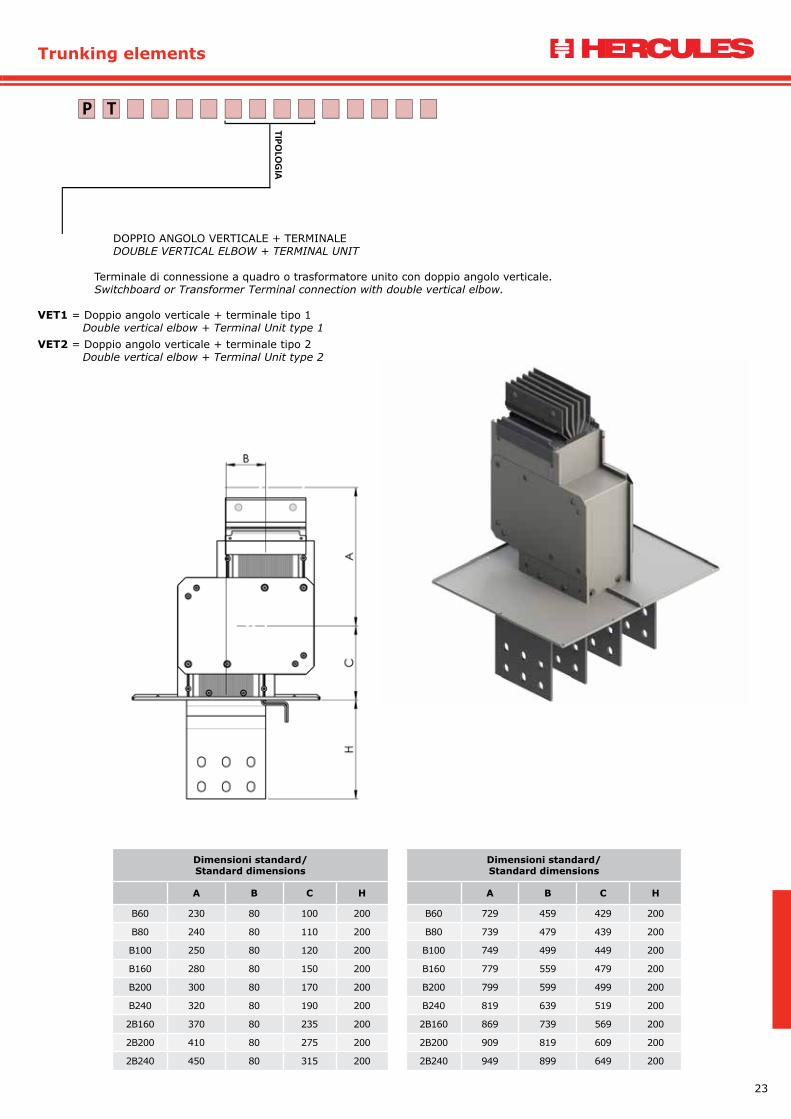
DOPPIO ANGOLO VERTICALE + TERMINALE DOUBLE VERTICAL ELBOW + TERMINAL UNIT
Terminale di connessione a quadro o trasformatore unito con doppio angolo verticale.Switchboard or Transformer Terminal connection with double vertical elbow.
VET1 = Doppio angolo verticale + terminale tipo 1 Double vertical elbow + Terminal Unit type 1VET2 = Doppio angolo verticale + terminale tipo 2 Double vertical elbow + Terminal Unit type 2
TP
TIPOLO
GIA
Dimensioni standard/Standard dimensions
A B C H
B60 230 80 100 200
B80 240 80 110 200
B100 250 80 120 200
B160 280 80 150 200
B200 300 80 170 200
B240 320 80 190 200
2B160 370 80 235 200
2B200 410 80 275 200
2B240 450 80 315 200
Dimensioni standard/Standard dimensions
A B C H
B60 729 459 429 200
B80 739 479 439 200
B100 749 499 449 200
B160 779 559 479 200
B200 799 599 499 200
B240 819 639 519 200
2B160 869 739 569 200
2B200 909 819 609 200
2B240 949 899 649 200

24
Elementi di percorso
ANGOLO ORIZZONTALE + VERTICALE + TERMINALEHORIZONTAL ELBOW + VERTICAL + TERMINAL UNIT
Terminale di connessione a quadro o trasformatore unito con angolo orizzontale + verticale.Switchboard or Transformer Terminal connection with horizontal + vertical elbow.
HVT1 = Angolo orizzontale + verticale + terminale tipo 1 Horizontal elbow + vertical + Terminal unit type 1 HVT2 = Angolo orizzontale + verticale + terminale tipo 2 Horizontal elbow + vertical + Terminal unit type 2 HVT3 = Angolo orizzontale + verticale + terminale tipo 3 Horizontal elbow + vertical + Terminal unit type 3 HVT4 = Angolo orizzontale + verticale + terminale tipo 4 Horizontal elbow + vertical + Terminal unit type 4
TP
TIPOLO
GIA
Dimensioni standard/Standard dimensions
A B C H
B60 250 180 100 200
B80 250 190 110 200
B100 250 200 120 200
B160 250 230 150 200
B200 250 250 170 200
B240 250 270 190 200
2B160 250 315 235 200
2B200 250 355 275 200
2B240 250 395 315 200
Dimensioni standard/Standard dimensions
A B C H
B60 749 479 429 200
B80 749 489 439 200
B100 749 499 449 200
B160 749 429 479 200
B200 749 549 499 200
B240 749 569 519 200
2B160 749 619 569 200
2B200 749 659 609 200
2B240 749 699 649 200
25
Trunking elements
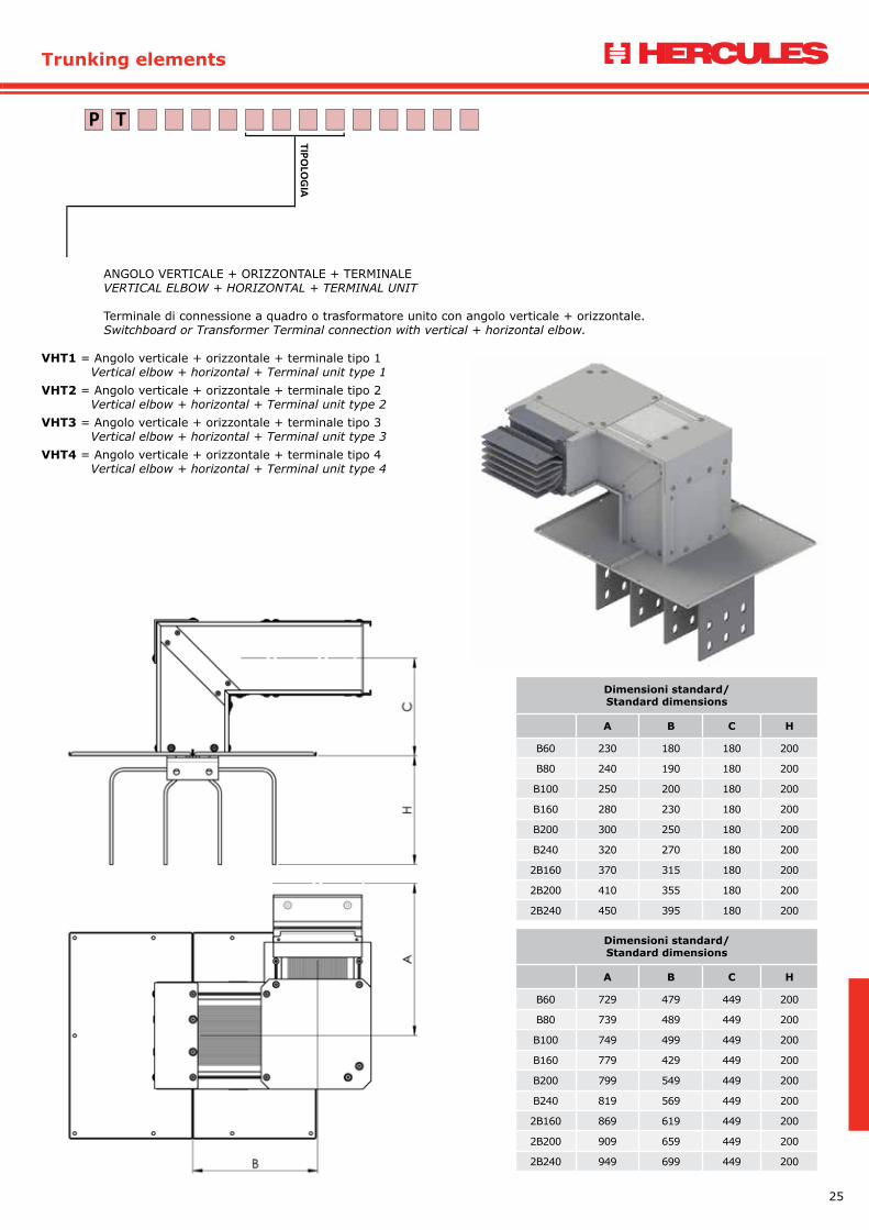
ANGOLO VERTICALE + ORIZZONTALE + TERMINALE VERTICAL ELBOW + HORIZONTAL + TERMINAL UNIT
Terminale di connessione a quadro o trasformatore unito con angolo verticale + orizzontale. Switchboard or Transformer Terminal connection with vertical + horizontal elbow.
VHT1 = Angolo verticale + orizzontale + terminale tipo 1 Vertical elbow + horizontal + Terminal unit type 1VHT2 = Angolo verticale + orizzontale + terminale tipo 2 Vertical elbow + horizontal + Terminal unit type 2VHT3 = Angolo verticale + orizzontale + terminale tipo 3 Vertical elbow + horizontal + Terminal unit type 3VHT4 = Angolo verticale + orizzontale + terminale tipo 4 Vertical elbow + horizontal + Terminal unit type 4
TP
TIPOLO
GIA
Dimensioni standard/Standard dimensions
A B C H
B60 230 180 180 200
B80 240 190 180 200
B100 250 200 180 200
B160 280 230 180 200
B200 300 250 180 200
B240 320 270 180 200
2B160 370 315 180 200
2B200 410 355 180 200
2B240 450 395 180 200
Dimensioni standard/Standard dimensions
A B C H
B60 729 479 449 200
B80 739 489 449 200
B100 749 499 449 200
B160 779 429 449 200
B200 799 549 449 200
B240 819 569 449 200
2B160 869 619 449 200
2B200 909 659 449 200
2B240 949 699 449 200

26
Alimentazione
ALIMENTAZIONE END FEEDER
Box di alimentazione linea.Box power line.
FED1 = Alimentazione standard End Feeder StandardFED2 = Alimentazione speciale End Feeder SpecialFVR1 = Alimentazione tratti verticali tipo 1 standard End Feeder for vertical runs type 1 Standard FVR2 = Alimentazione tratti verticali tipo 2 standard End Feeder for vertical runs type 2 StandardFVR3 = Alimentazione tratti verticali tipo 1 speciale End Feeder for vertical runs type 1 SpecialFVR4 = Alimentazione tratti verticali tipo 2 speciale End Feeder for vertical runs type 2 Special
TP
TIPOLO
GIA
ALIMENTAZIONEEND FEEDER
ALIMENTAZIONE TRATTI VERTICALIEND FEEDER FOR VERTICAL RUNS
27
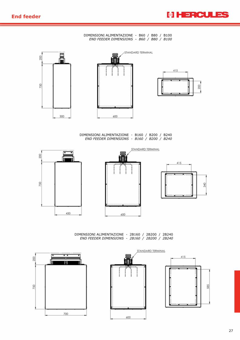
End feeder
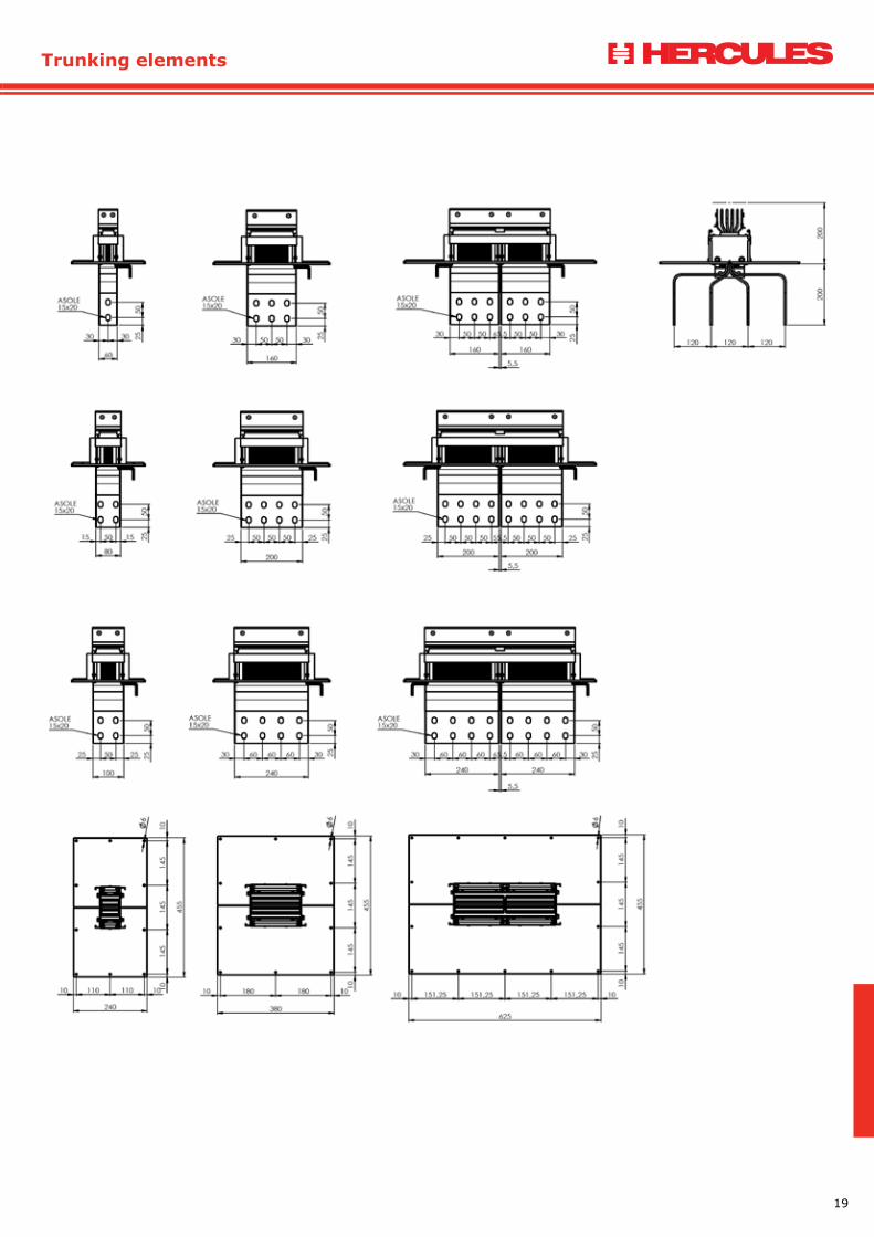
DIMENSIONI ALIMENTAZIONE - B60 / B80 / B100END FEEDER DIMENSIONS - B60 / B80 / B100
DIMENSIONI ALIMENTAZIONE - B160 / B200 / B240END FEEDER DIMENSIONS - B160 / B200 / B240
DIMENSIONI ALIMENTAZIONE - 2B160 / 2B200 / 2B240END FEEDER DIMENSIONS - 2B160 / 2B200 / 2B240

28
Accessori
TERMINALE FASI PARALLELE TERMINAL WITH PARALLEL PHASES
Terminale di connessione a quadro o trasformatore con uscita barre in parallelo rispetto all’andamento del condotto.Terminal connection switchboard or transformer with output bars parallel respect the run of the duct.
TPP1 = Terminale fasi parallele tipo 1 Terminal with parallel phases type 1 TPP2 = Terminale fasi parallele tipo 2 Terminal with parallel phases type 2
TP
TIPOLO
GIA
Questo elemento viene studiato e realizzato dal ns. uff. engineering in base alle condizioni di utilizzo.This element will be studied and designed by our engineering department according to installation conditions.

29
Accessories
TERMINALE FASI PARALLELE TERMINAL WITH PARALLEL PHASES
Terminale di connessione a quadro o trasformatore con uscita barre in parallelo rispetto all’andamento del condotto.Terminal connection switchboard or transformer with output bars parallel respect the run of the duct.
TPP1 = Terminale fasi parallele tipo 1 Terminal with parallel phases type 1 TPP2 = Terminale fasi parallele tipo 2 Terminal with parallel phases type 2
TP
TIPOLO
GIA
MONOBLOCCO MONOBLOCK
MON1 = Monoblocco Monoblock
CHIUSURA CONGIUNZIONE JOINT COVER
JCO1 = Chiusura congiunzione Joint Cover
CHIUSURA ESTREMITA’ END COVER
ECO1 = Chiusura estremità End Cover
STAFFAGGIO FIXING UNIT
FIUS = Staffa universale Universal fixing unitFVS1 = Staffa a molla per tratti verticali Fixing unit for vertical runsFVA1 = Staffa allineamento per tratti verticali Fixing unit for vertical runs alignment
Prego considerare N°1 CHIUSURA CONGIUNZIONE e N°1 MONOBLOCCO per ogni elemento di percorso.Please consider N°1 JOINT COVER and N°1 MONOBLOCK for each trunking element.
FVS1FVA1
30
Accessori
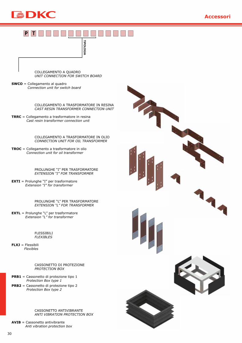
COLLEGAMENTO A QUADRO UNIT CONNECTION FOR SWITCH BOARD
SWCO = Collegamento al quadro Connection unit for switch board
TP
TIPOLO
GIA
COLLEGAMENTO A TRASFORMATORE IN RESINACAST RESIN TRANSFORMER CONNECTION UNIT
TRRC = Collegamento a trasformatore in resina Cast resin transformer connection unit
COLLEGAMENTO A TRASFORMATORE IN OLIOCONNECTION UNIT FOR OIL TRANSFORMER
TROC = Collegamento a trasformatore in olio Connection unit for oil transformer
PROLUNGHE “I” PER TRASFORMATOREEXTENSION “I” FOR TRANSFORMER
EXTI = Prolunghe “I” per trasformatore Extension “I” for transformer
PROLUNGHE “L” PER TRASFORMATOREEXTENSION “L” FOR TRANSFORMER
EXTL = Prolunghe “L” per trasformatore Extension “L” for transformer
FLESSIBILIFLEXIBLES
FLXJ = Flessibili Flexibles
CASSONETTO DI PROTEZIONE PROTECTION BOX
PRB1 = Cassonetto di protezione tipo 1 Protection Box type 1PRB2 = Cassonetto di protezione tipo 2 Protection Box type 2
CASSONETTO ANTIVIBRANTE ANTI VIBRATION PROTECTION BOX
AVIB = Cassonetto antivibrante Anti vibration protection box
31
Tap off box
TP
TIPOLO
GIA
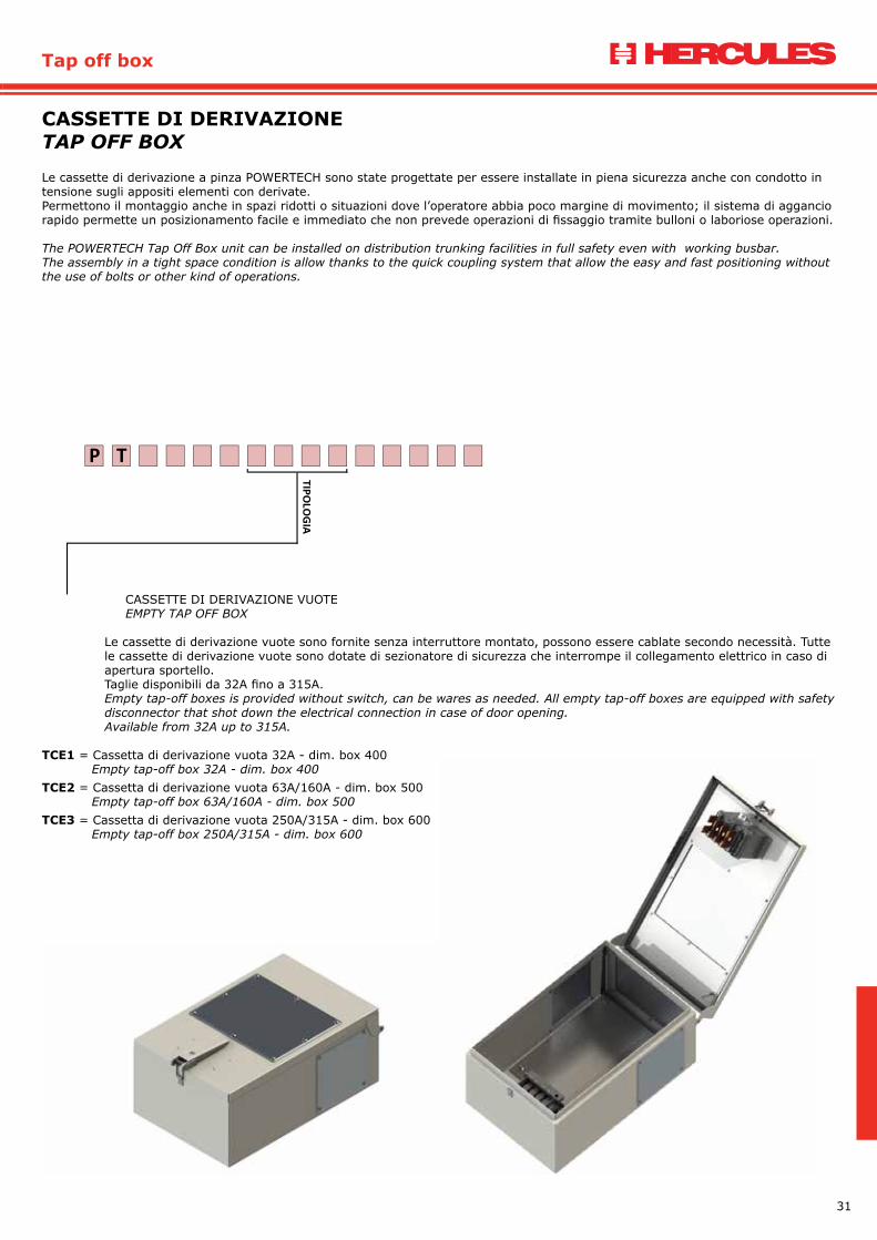
CASSETTE DI DERIVAZIONE VUOTEEMPTY TAP OFF BOX
Le cassette di derivazione vuote sono fornite senza interruttore montato, possono essere cablate secondo necessità. Tutte le cassette di derivazione vuote sono dotate di sezionatore di sicurezza che interrompe il collegamento elettrico in caso di apertura sportello. Taglie disponibili da 32A fino a 315A. Empty tap-off boxes is provided without switch, can be wares as needed. All empty tap-off boxes are equipped with safety disconnector that shot down the electrical connection in case of door opening.Available from 32A up to 315A.
TCE1 = Cassetta di derivazione vuota 32A - dim. box 400 Empty tap-off box 32A - dim. box 400TCE2 = Cassetta di derivazione vuota 63A/160A - dim. box 500 Empty tap-off box 63A/160A - dim. box 500TCE3 = Cassetta di derivazione vuota 250A/315A - dim. box 600 Empty tap-off box 250A/315A - dim. box 600
Le cassette di derivazione a pinza POWERTECH sono state progettate per essere installate in piena sicurezza anche con condotto in tensione sugli appositi elementi con derivate. Permettono il montaggio anche in spazi ridotti o situazioni dove l’operatore abbia poco margine di movimento; il sistema di aggancio rapido permette un posizionamento facile e immediato che non prevede operazioni di fissaggio tramite bulloni o laboriose operazioni.
The POWERTECH Tap Off Box unit can be installed on distribution trunking facilities in full safety even with working busbar.The assembly in a tight space condition is allow thanks to the quick coupling system that allow the easy and fast positioning without the use of bolts or other kind of operations.
CASSETTE DI DERIVAZIONETAP OFF BOX
32
Cassette di derivazione
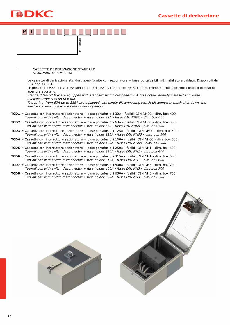
CASSETTE DI DERIVAZIONE STANDARD STANDARD TAP OFF BOX
Le cassette di derivazione standard sono fornite con sezionatore + base portafusibili già installato e cablato. Disponibili da 63A fino a 630A.Le portate da 63A fino a 315A sono dotate di sezionatore di sicurezza che interrompe il collegamento elettrico in caso di apertura sportello. Standard tap off box are equipped with standard switch disconnector + fuse holder already installed and wired.Available from 63A up to 630A.The rating from 63A up to 315A are equipped with safety disconnecting switch disconnector which shot down the electrical connection in the case of door opening.
TCD1 = Cassetta con interruttore sezionatore + base portafusibili 32A - fusibili DIN NH0C - dim. box 400 Tap-off box with switch disconnector + fuse holder 32A - fuses DIN NH0C - dim. box 400TCD2 = Cassetta con interruttore sezionatore + base portafusibili 63A - fusibili DIN NH00 - dim. box 500 Tap-off box with switch disconnector + fuse holder 63A - fuses DIN NH00 - dim. box 500TCD3 = Cassetta con interruttore sezionatore + base portafusibili 125A - fusibili DIN NH00 - dim. box 500 Tap-off box with switch disconnector + fuse holder 125A - fuses DIN NH00 - dim. box 500TCD4 = Cassetta con interruttore sezionatore + base portafusibili 160A - fusibili DIN NH00 - dim. box 500 Tap-off box with switch disconnector + fuse holder 160A - fuses DIN NH00 - dim. box 500TCD5 = Cassetta con interruttore sezionatore + base portafusibili 250A - fusibili DIN NH1 - dim. box 600 Tap-off box with switch disconnector + fuse holder 250A - fuses DIN NH1 - dim. box 600TCD6 = Cassetta con interruttore sezionatore + base portafusibili 315A - fusibili DIN NH1 - dim. box 600 Tap-off box with switch disconnector + fuse holder 315A - fuses DIN NH1 - dim. box 600TCD7 = Cassetta con interruttore sezionatore + base portafusibili 400A - fusibili DIN NH3 - dim. box 700 Tap-off box with switch disconnector + fuse holder 400A - fuses DIN NH3 - dim. box 700TCD8 = Cassetta con interruttore sezionatore + base portafusibili 630A - fusibili DIN NH3 - dim. box 700 Tap-off box with switch disconnector + fuse holder 630A - fuses DIN NH3 - dim. box 700
TP
TIPOLO
GIA

33
Tap off box
CASSETTE DI DERIVAZIONE PREDISPOSTE PREFITTED TAP OFF BOX
Le cassette di derivazione, a richiesta possono essere fornite già predisposte per la maggior parte degli MCCB presenti in commercio, consultare il ns. ufficio engineering per informazioni dettagliate.Tap off boxes, on request, can be prefitted with the most used MCCB in the market, contact our. engineering office for more details.
TCT1 = Cassetta predisposta per MCCB TMax T1 ABB SACE / Tap-off box pre-fitted for MCCB TMax T1 ABB SACETCT2 = Cassetta predisposta per MCCB TMax T2 ABB SACE / Tap-off box pre-fitted for MCCB TMax T2 ABB SACETCT3 = Cassetta predisposta per MCCB TMax T3 ABB SACE / Tap-off box pre-fitted for MCCB TMax T3 ABB SACETCT4 = Cassetta predisposta per MCCB TMax T4 ABB SACE / Tap-off box pre-fitted for MCCB TMax T4 ABB SACETCT5 = Cassetta predisposta per MCCB TMax T5 ABB SACE / Tap-off box pre-fitted for MCCB TMax T5 ABB SACETCT6 = Cassetta predisposta per MCCB TMax T6 ABB SACE / Tap-off box pre-fitted for MCCB TMax T6 ABB SACETCT7 = Cassetta predisposta per MCCB TMax T7 ABB SACE / Tap-off box pre-fitted for MCCB TMax T7 ABB SACETCX1 = Cassetta predisposta per MCCB TMax XT1 ABB SACE / Tap-off box pre-fitted for MCCB TMax XT1 ABB SACETCX2 = Cassetta predisposta per MCCB TMax XT2 ABB SACE / Tap-off box pre-fitted for MCCB TMax XT2 ABB SACETCX3 = Cassetta predisposta per MCCB TMax XT3 ABB SACE / Tap-off box pre-fitted for MCCB TMax XT3 ABB SACETCX4 = Cassetta predisposta per MCCB TMax XT4 ABB SACE / Tap-off box pre-fitted for MCCB TMax XT4 ABB SACETCN1 = Cassetta predisposta per MCCB NS100 Schneider / Tap-off box pre-fitted for MCCB NS100 Schneider TCN2 = Cassetta predisposta per MCCB NS160 Schneider / Tap-off box pre-fitted for MCCB NS160 Schneider TCN3 = Cassetta predisposta per MCCB NS250 Schneider / Tap-off box pre-fitted for MCCB NS250 Schneider TCN4 = Cassetta predisposta per MCCB NS400 Schneider / Tap-off box pre-fitted for MCCB NS400 Schneider TCN5 = Cassetta predisposta per MCCB NS630 Schneider / Tap-off box pre-fitted for MCCB NS630 Schneider TCY1 = Cassetta predisposta per MCCB NSX100 Schneider / Tap-off box pre-fitted for MCCB NSX100 Schneider TCY2 = Cassetta predisposta per MCCB NSX160 Schneider / Tap-off box pre-fitted for MCCB NSX160 Schneider TCY3 = Cassetta predisposta per MCCB NSX250 Schneider / Tap-off box pre-fitted for MCCB NSX250 Schneider TCY4 = Cassetta predisposta per MCCB NSX400 Schneider / Tap-off box pre-fitted for MCCB NSX400 Schneider TCY5 = Cassetta predisposta per MCCB NSX630 Schneider / Tap-off box pre-fitted for MCCB NSX630 Schneider TCP1 = Cassetta predisposta per MCCB DPX 125 Legrand / Tap-off box pre-fitted for MCCB DPX 125 LegrandTCP2 = Cassetta predisposta per MCCB DPX 160 Legrand / Tap-off box pre-fitted for MCCB DPX 160 LegrandTCP3 = Cassetta predisposta per MCCB DPX 250 Legrand / Tap-off box pre-fitted for MCCB DPX 250 LegrandTCP4 = Cassetta predisposta per MCCB DPX 250ER Legrand / Tap-off box pre-fitted for MCCB DPX 250ER LegrandTCP5 = Cassetta predisposta per MCCB DPX 630 Legrand / Tap-off box pre-fitted for MCCB DPX 630 Legrand
TP
TIPOLO
GIA

34
Cassette di derivazione
CASSETTE DI DERIVAZIONE PREDISPOSTE PREFITTED TAP OFF BOX
TCL1 = Cassetta predisposta per MCCB 3VL1 SIEMENS / Tap-off box pre-fitted for MCCB 3VL1 SIEMENSTCL2 = Cassetta predisposta per MCCB 3VL2 SIEMENS / Tap-off box pre-fitted for MCCB 3VL2 SIEMENSTCL3 = Cassetta predisposta per MCCB 3VL3 SIEMENS / Tap-off box pre-fitted for MCCB 3VL3 SIEMENSTCL4 = Cassetta predisposta per MCCB 3VL4 SIEMENS / Tap-off box pre-fitted for MCCB 3VL4 SIEMENSTCL5 = Cassetta predisposta per MCCB 3VL5 SIEMENS / Tap-off box pre-fitted for MCCB 3VL5 SIEMENSTCL6 = Cassetta predisposta per MCCB 3VL6 SIEMENS / Tap-off box pre-fitted for MCCB 3VL6 SIEMENSTCL7 = Cassetta predisposta per MCCB 3VL7 SIEMENS / Tap-off box pre-fitted for MCCB 3VL7 SIEMENSTCA1 = Cassetta predisposta per MCCB 3VA10 SIEMENS / Tap-off box pre-fitted for MCCB 3VA10 SIEMENSTCA2 = Cassetta predisposta per MCCB 3VA11 SIEMENS / Tap-off box pre-fitted for MCCB 3VA11 SIEMENSTCA3 = Cassetta predisposta per MCCB 3VA20 SIEMENS / Tap-off box pre-fitted for MCCB 3VA20 SIEMENSTCA4 = Cassetta predisposta per MCCB 3VA21 SIEMENS / Tap-off box pre-fitted for MCCB 3VA21 SIEMENSTCA5 = Cassetta predisposta per MCCB 3VA22 SIEMENS / Tap-off box pre-fitted for MCCB 3VA22 SIEMENSTCA6 = Cassetta predisposta per MCCB 3VA23 SIEMENS / Tap-off box pre-fitted for MCCB 3VA23 SIEMENSTCA7 = Cassetta predisposta per MCCB 3VA24 SIEMENS / Tap-off box pre-fitted for MCCB 3VA24 SIEMENS
TCM1 = Cassetta predisposta per interruttori modulari MCB 4 moduli Tap-off box pre-fitted for modular switches MCB 4 modulesTCM2 = Cassetta predisposta per interruttori modulari MCB 8 moduli Tap-off box pre-fitted for modular switches MCB 8 modulesTCM3 = Cassetta predisposta per interruttori modulari MCB 12 moduli Tap-off box pre-fitted for modular switches MCB 12 modules
TP
TIPOLO
GIA
35
Tap off box
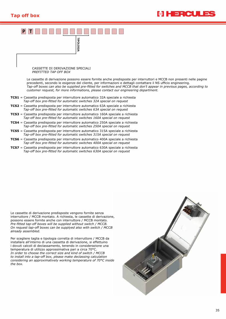
CASSETTE DI DERIVAZIONE SPECIALIPREFITTED TAP OFF BOX
Le cassette di derivazione possono essere fornite anche predisposte per interruttori e MCCB non presenti nelle pagine precedenti, secondo le esigenze del cliente, per informazioni e dettagli contattare il NS ufficio engineering.Tap-off boxes can also be supplied pre-fitted for switches and MCCB that don’t appear in previous pages, according to customer request, for more informations, please contact our engineering department.
TCS1 = Cassetta predisposta per interruttore automatico 32A speciale a richiesta Tap-off box pre-fitted for automatic switches 32A special on requestTCS2 = Cassetta predisposta per interruttore automatico 63A speciale a richiesta Tap-off box pre-fitted for automatic switches 63A special on requestTCS3 = Cassetta predisposta per interruttore automatico 160A speciale a richiesta Tap-off box pre-fitted for automatic switches 160A special on requestTCS4 = Cassetta predisposta per interruttore automatico 250A speciale a richiesta Tap-off box pre-fitted for automatic switches 250A special on requestTCS5 = Cassetta predisposta per interruttore automatico 315A speciale a richiesta Tap-off box pre-fitted for automatic switches 315A special on requestTCS6 = Cassetta predisposta per interruttore automatico 400A speciale a richiesta Tap-off box pre-fitted for automatic switches 400A special on requestTCS7 = Cassetta predisposta per interruttore automatico 630A speciale a richiesta Tap-off box pre-fitted for automatic switches 630A special on request
TP
TIPOLO
GIA
Le cassette di derivazione predisposte vengono fornite senza interruttore / MCCB montato. A richiesta, le cassette di derivazione, possono essere fornite anche con interruttore / MCCB montato.Pre-fitted tap-off boxes will be supplied without switch / MCCB. On request tap-off boxes can be supplyed also with switch / MCCB already assembled.
Per scegliere taglia e tipologia corretta di interruttore / MCCB da installare all’interno di una cassetta di derivazione, si effettuino i dovuti calcoli di declassamento, tenendo in considerazione una temperatura di utilizzo approssimativa pari a circa 70°C.In order to choose the correct size and kind of switch / MCCB to install into a tap-off box, please make declassing calculation considering an approximatively working temperature of 70°C inside the box.

36
Cassette di derivazione
CASSETTA DI DERIVAZIONE L= 400
CASSETTA DI DERIVAZIONE L= 500
CASSETTA DI DERIVAZIONE L= 600
CASSETTA DI DERIVAZIONE L= 700

37
Tap off box
CASSETTA DI DERIVAZIONE L= 700 CASSETTE DI DERIVAZIONE DA INSTALLARE SULLA CONGIUNZIONE TAP OFF BOX TO BE ASSEMBLED ON THE JUNCTIONLe cassette di derivazione a pinza POWERTECH coprono portate fino a 630A, qualora vi fosse la necessità di portate maggiori, da 800A fino a 1600A, sono disponibili cassette di derivazione da montare sulla congiunzione. Le cassette di derivazione sulla congiunzione, sono studiate per essere montate nella connessione tra due elementi e non necessitano di elementi con derivate per essere installati; per questo motivo il montaggio va effettuato rigorosamente con linea non in tensione.Al momento dell’ordine è necessario specificare tipologia e portata della linea su cui dovrà essere installata la derivazione, poichè per ogni dimensione condotto è necessario una diversa tipologia di collegamento.A richiesta, in caso di necessità, le cassette di derivazione sulla congiunzione possono essere fornite anche con taglie da 63A fino 630A; le dimensioni del box variano a seconda della portata richiesta.
POWERTECH plug in tap-off boxes cover ratings up to 630A, if there is a need of transport more power, from 800A up to 1600A, are available boxes to be mounted on the junction.Junction Tap-off boxes are designed to be mounted in the connection between two elements and do not need plug-in elements to be installed; for this reason installation should be done only without tension in the line.While ordering is necessary to specify type and rating of the line on which it will be installed the box, as for any duct size is required a different type of connection.On request, if necessary, the junction boxes on the conjunction can also be supplied with sizes from 63A to 630A; dimensions of the box will depend of the rating required.
38
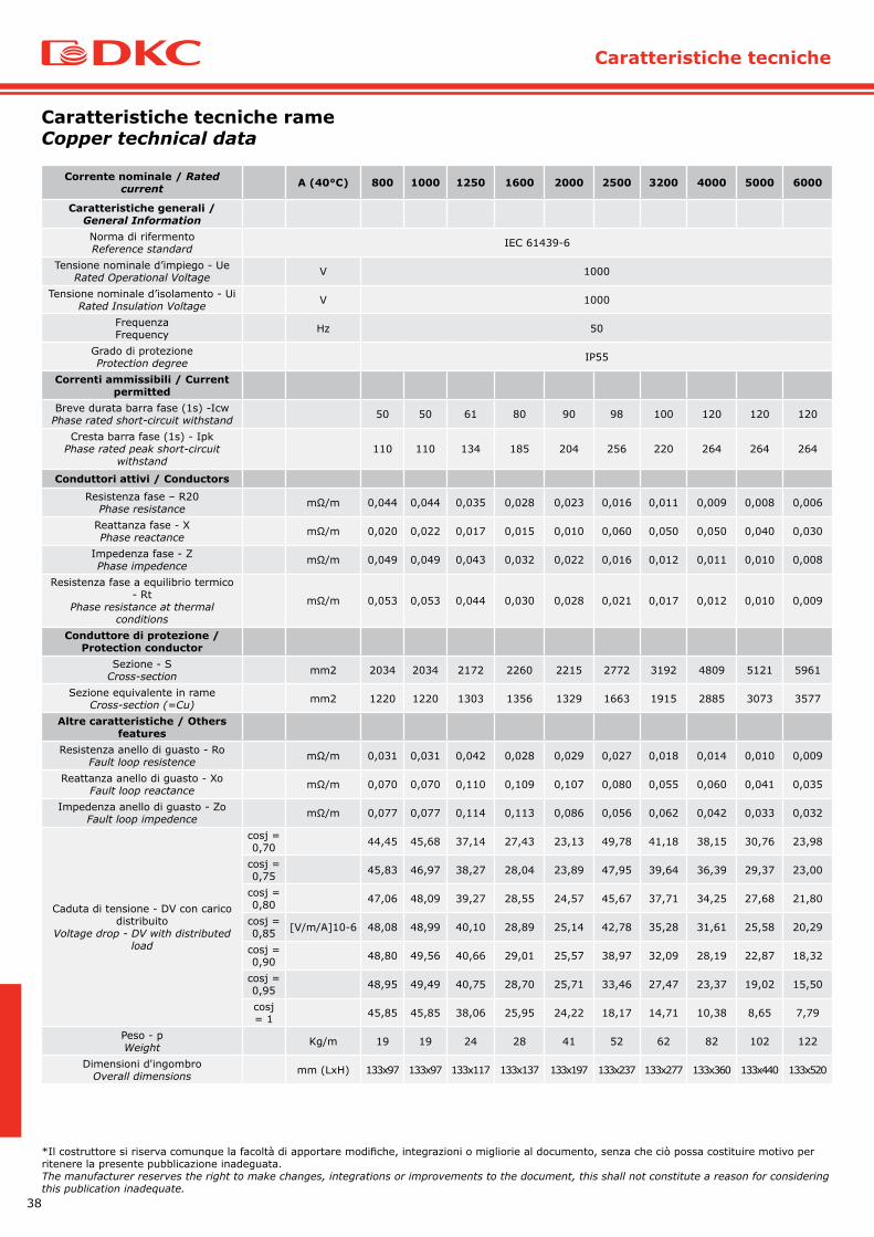
Corrente nominale / Rated current A (40°C) 800 1000 1250 1600 2000 2500 3200 4000 5000 6000
Caratteristiche generali / General InformationNorma di rifermentoReference standard IEC 61439-6
Tensione nominale d’impiego - UeRated Operational Voltage V 1000
Tensione nominale d’isolamento - UiRated Insulation Voltage V 1000
FrequenzaFrequency Hz 50
Grado di protezioneProtection degree IP55
Correnti ammissibili / Current permitted
Breve durata barra fase (1s) -IcwPhase rated short-circuit withstand 50 50 61 80 90 98 100 120 120 120
Cresta barra fase (1s) - IpkPhase rated peak short-circuit
withstand110 110 134 185 204 256 220 264 264 264
Conduttori attivi / ConductorsResistenza fase – R20
Phase resistance mΩ/m 0,044 0,044 0,035 0,028 0,023 0,016 0,011 0,009 0,008 0,006
Reattanza fase - XPhase reactance mΩ/m 0,020 0,022 0,017 0,015 0,010 0,060 0,050 0,050 0,040 0,030
Impedenza fase - ZPhase impedence mΩ/m 0,049 0,049 0,043 0,032 0,022 0,016 0,012 0,011 0,010 0,008
Resistenza fase a equilibrio termico - Rt
Phase resistance at thermal conditions
mΩ/m 0,053 0,053 0,044 0,030 0,028 0,021 0,017 0,012 0,010 0,009
Conduttore di protezione / Protection conductor
Sezione - SCross-section mm2 2034 2034 2172 2260 2215 2772 3192 4809 5121 5961
Sezione equivalente in rameCross-section (=Cu) mm2 1220 1220 1303 1356 1329 1663 1915 2885 3073 3577
Altre caratteristiche / Others features
Resistenza anello di guasto - RoFault loop resistence mΩ/m 0,031 0,031 0,042 0,028 0,029 0,027 0,018 0,014 0,010 0,009
Reattanza anello di guasto - XoFault loop reactance mΩ/m 0,070 0,070 0,110 0,109 0,107 0,080 0,055 0,060 0,041 0,035
Impedenza anello di guasto - ZoFault loop impedence mΩ/m 0,077 0,077 0,114 0,113 0,086 0,056 0,062 0,042 0,033 0,032
Caduta di tensione - DV con carico distribuito
Voltage drop - DV with distributed load
cosj = 0,70 44,45 45,68 37,14 27,43 23,13 49,78 41,18 38,15 30,76 23,98
cosj = 0,75 45,83 46,97 38,27 28,04 23,89 47,95 39,64 36,39 29,37 23,00
cosj = 0,80 47,06 48,09 39,27 28,55 24,57 45,67 37,71 34,25 27,68 21,80
cosj = 0,85 [V/m/A]10-6 48,08 48,99 40,10 28,89 25,14 42,78 35,28 31,61 25,58 20,29
cosj = 0,90 48,80 49,56 40,66 29,01 25,57 38,97 32,09 28,19 22,87 18,32
cosj = 0,95 48,95 49,49 40,75 28,70 25,71 33,46 27,47 23,37 19,02 15,50
cosj = 1 45,85 45,85 38,06 25,95 24,22 18,17 14,71 10,38 8,65 7,79
Peso - pWeight Kg/m 19 19 24 28 41 52 62 82 102 122
Dimensioni d'ingombroOverall dimensions mm (LxH) 133x97 133x97 133x117 133x137 133x197 133x237 133x277 133x360 133x440 133x520
Caratteristiche tecniche rameCopper technical data
*Il costruttore si riserva comunque la facoltà di apportare modifiche, integrazioni o migliorie al documento, senza che ciò possa costituire motivo per ritenere la presente pubblicazione inadeguata.The manufacturer reserves the right to make changes, integrations or improvements to the document, this shall not constitute a reason for considering this publication inadequate.
Caratteristiche tecniche

39
Technical data
Corrente nominale / Rated current A (40°C) 630 800 1000 1250 1600 2000 2500 3200 4000 5000
Caratteristiche generali / General InformationNorma di rifermentoReference standard IEC 61439-6
Tensione nominale d’impiego - UeRated Operational Voltage V 1000
Tensione nominale d’isolamento - UiRated Insulation Voltage V 1000
FrequenzaFrequency Hz 50
Grado di protezioneProtection degree IP55
Correnti ammissibili / Current permitted
Breve durata barra fase (1s) -IcwPhase rated short-circuit withstand 35 35 53 56 80 90 100 120 120 120
Cresta barra fase (1s) - IpkPhase rated peak short-circuit
withstand77 77 116,6 123,2 176 198 220 264 264 264
Conduttori attivi / ConductorsResistenza fase – R20
Phase resistance mΩ/m 0,093 0,076 0,062 0,046 0,035 0,028 0,021 0,017 0,014 0,011
Reattanza fase - XPhase reactance mΩ/m 0,048 0,023 0,018 0,016 0,012 0,010 0,008 0,007 0,006 0,004
Impedenza fase - ZPhase impedence mΩ/m 0,113 0,084 0,071 0,146 0,040 0,031 0,025 0,020 0,014 0,012
Resistenza fase a equilibrio termico - Rt
Phase resistance at thermal conditions
mΩ/m 0,103 0,089 0,073 0,055 0,041 0,033 0,025 0,020 0,017 0,012
Conduttore di protezione / Protection conductor
Sezione - SCross-section mm2 2034 2034 2172 2260 2215 2772 3192 4809 5121 5961
Sezione equivalente in rameCross-section (=Cu) mm2 1220 1220 1303 1356 1329 1663 1915 2885 3073 3577
Altre caratteristiche / Others features
Resistenza anello di guasto - RoFault loop resistence mΩ/m 0,136 0,143 0,118 0,096 0,079 0,069 0,058 0,047 0,042 0,034
Reattanza anello di guasto - XoFault loop reactance mΩ/m 0,112 0,102 0,094 0,071 0,060 0,050 0,033 0,027 0,027 0,014
Impedenza anello di guasto - ZoFault loop impedence mΩ/m 0,271 0,237 0,220 0,192 0,154 0,138 0,104 0,083 0,076 0,064
Caduta di tensione - DV con carico distribuito
Voltage drop - DV with distributed load
cosj = 0,70 92,02 67,89 55,56 42,75 32,33 26,33 20,01 16,48 14,45 9,95
cosj = 0,75 94,28 70,71 57,92 44,40 33,59 27,32 20,73 17,06 14,92 10,27
cosj = 0,80 96,19 73,37 60,13 45,93 34,76 28,23 21,39 17,58 15,35 10,56
cosj = 0,85 [V/m/A]10-6 97,60 75,80 62,16 47,31 35,80 29,05 21,97 18,04 15,70 10,81
cosj = 0,90 98,28 77,88 63,92 48,44 36,67 29,71 22,43 18,40 15,97 10,98
cosj = 0,95 97,60 79,32 65,17 49,14 37,21 30,09 22,67 18,57 16,05 11,04
cosj = 1 89,10 77,09 63,47 47,28 35,83 28,86 21,63 17,65 15,12 10,38
Peso - pWeight Kg/m 10 10 12 14 19 23 27 37 44 52
Dimensioni d'ingombroOverall dimensions mm (LxH) 133x97 133x97 133x117 133x137 133x197 133x237 133x277 133x360 133x440 133x520
Caratteristiche tecniche alluminioAluminium technical data
*Il costruttore si riserva comunque la facoltà di apportare modifiche, integrazioni o migliorie al documento, senza che ciò possa costituire motivo per ritenere la presente pubblicazione inadeguata.The manufacturer reserves the right to make changes, integrations or improvements to the document, this shall not constitute a reason for considering this publication inadequate.

40
Istruzioni di montaggio
ISTRUZIONI DI MONTAGGIOINSTALLATION INSTRUCTIONS
FASE 1 - STAGE 1
Tutti gli elementi di percorso (elementi rettilinei, angoli, terminali,ecc…) non hanno i monoblocchi montati e questi vengono consegnati in scatole di cartone per evitare sia i danneggiamenti che si possono verificare durante il trasporto sia la possibilità di furto durante lo stoccaggio in cantiere del materiale.
All elements of busbar (straight elements, elbows, terminals, etc ...) do not have the monoblocks mounted and these are delivered in cardboard boxes to prevent both damage that may occur during transport is the possibility of theft during storage in building site.
FASE 2 - STAGE 2
Montare il monoblocco sul primo elemento. Il corretto montaggio è facilitato e garantito da 3 fattori:1. Il simbolo “giallo/verde” presente solo su un lato dell’elemento
e del monoblocco. I simboli devono essere vicini e sullo stesso lato.
2. La presenza di bugne che vanno ad accoppiarsi al corretto montaggio del monoblocco. Se il montaggio non è avvenuto in modo corretto, non vi è un perfetto accoppiamento e parallelismo tra piastra del monoblocco e il conduttore di terra dell’elemento.
3. La presenza di 2 piastre di lunghezza diversa che devono coincidere perfettamente con i fermi posizionati sui conduttori di terra dell’elemento. Queste 2 piastre servono anche per evitare l’inversione fasi tra i 2 elementi che si stanno montando.
Mount the monoblock on the first element. Correct assembly is facilitated and secured by 3 factors:1. The “yellow / green” present only on one side of the element
and monoblock. The symbols must be close and on the same side.
2. The presence of the studs that go to couple the correct assembly of the monoblock. If the installation was not done properly, there is no a perfect fit and parallelism between the monoblock’s plate and earth conductor of the element.
3. The presence of two plates of different length that must match perfectly with the clips placed on the earth conductors of the element. These two plates are also used to prevent the reversal phases between the two elements that are mounting.
41
Installation instructions
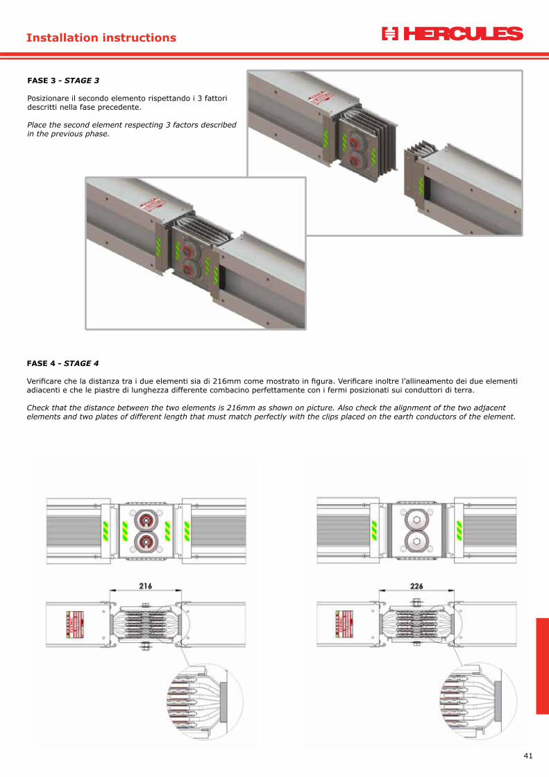
FASE 3 - STAGE 3
Posizionare il secondo elemento rispettando i 3 fattori descritti nella fase precedente.
Place the second element respecting 3 factors described in the previous phase.
FASE 4 - STAGE 4
Verificare che la distanza tra i due elementi sia di 216mm come mostrato in figura. Verificare inoltre l’allineamento dei due elementi adiacenti e che le piastre di lunghezza differente combacino perfettamente con i fermi posizionati sui conduttori di terra.
Check that the distance between the two elements is 216mm as shown on picture. Also check the alignment of the two adjacent elements and two plates of different length that must match perfectly with the clips placed on the earth conductors of the element.
42
Istruzioni di montaggio
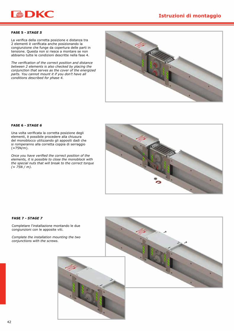
FASE 5 - STAGE 5
La verifica della corretta posizione e distanza tra 2 elementi è verificata anche posizionando la congiunzione che funge da copertura delle parti in tensione. Questa non si riesce a montare se non abbiamo tutte le condizioni descritte nella fase 4.
The verification of the correct position and distance between 2 elements is also checked by placing the conjunction that serves as the cover of the energized parts. You cannot mount it if you don’t have all conditions described for phase 4.
FASE 6 - STAGE 6
Una volta verificata la corretta posizione degli elementi, è possibile procedere alla chiusura del monoblocco utilizzando gli appositi dadi che si romperanno alla corretta coppia di serraggio (≈75N/m).
Once you have verified the correct position of the elements, it is possible to close the monoblock with the special nuts that will break to the correct torque (≈ 75N / m).
FASE 7 - STAGE 7
Completare l’installazione montando le due congiunzioni con le apposite viti.
Complete the installation mounting the two conjunctions with the screws.

43
Certifications
CERTIFICAZIONICERTIFICATIONS

44
Note


DKC Europe S.r.l.Via Libertà, 207 - 28043 Bellinzago Novarese (No)
Tel +39 0321 989898e-mail [email protected]
www.dkceurope.eu