NON bagnare l imballo NON calpestare l imballo Maneggiare ... · Leggere attentamente e...
28
IPR3UJ - 6772051_01 Pannello remoto semplificato • Remote panel Panneau de commande a distance simplifie • Fernbedienungstableau Panel remoto simplificado PR 3 remoto semplificato de a distance simpl Panel remoto simp
Transcript of NON bagnare l imballo NON calpestare l imballo Maneggiare ... · Leggere attentamente e...

IPR3UJ - 6772051_01
�� �� �� �
Pannello remoto semplifi cato • Remote panelPanneau de commande a distance simplifi e • Fernbedienungstableau
Panel remoto simplifi cado
PR 3
remoto semplifi catode a distance simpl
Panel remoto simp
PR3_new.indd 1 24/06/2009 12.07.17

NON bagnare l’imballo NON calpestare l’imballo Maneggiare con cautela
Simboli di sicurezza
�Pericolo tensione Attenzione Pericolo organi in movimento
Precauzioni e norme di sicurezza
Conservare i manuali in luogo asciutto, per evitare il deterioramento, per almeno 10 anni per eventuali riferimenti futuri.Leggere attentamente e completamente tutte le informazioni contenute in que-sto manuale. Prestare particolarmente attenzione alle norme d’uso accompa-gnate dalle scritte “PERICOLO” o “ATTENZIONE” in quanto, se non osservate, possono causare danno alla macchina e/o a persone e cose. Per anomalie non contemplate da questo manuale, interpellare tempestivamente il Servizio Assi-stenza di zona. L'apparecchio deve essere installato in maniera tale da rende-re possibili operazioni di manutenzione e/o riparazione.
La garanzia dell'apparecchio non copre in ogni caso i costi dovuti ad autoscale, ponteggi o altri sistemi di elevazione che si rendessero necessari per effettuare gli interventi in garanzia. AERMEC S.p.A. declina ogni responsabilità per qualsiasi danno dovuto ad un uso improprio della macchina, ad una lettura parziale o super-fi ciale delle informazioni contenute in questo manuale.
Attenzione: questo prodotto contiene apparecchiature elettriche ed elettroniche che non possono essere smaltite attraverso i normali canali di raccolta dei rifi uti munici-pali. Esistono centri di raccolta differenziata per questi prodotti.
Le apparecchiature elettriche ed elettroniche devono essere trattate separatamente ed in accordo alle legislazioni vigenti nello stato di appartenenza. Batterie o accumulatori presenti negli apparecchi devono essere smaltiti sepa-ratamente secondo le disposizioni del comune di appartenenza.
Indicazioni sullo smaltimento Note sulla manualistica
Note sulla dichiarazione di conformità CE
L'accessorio descritto nel presente manuale, può essere utilizzato solo ed esclusivamente in abbinamento con le macchine per le quali è stato progettato. Soddisfacendo questa condizione è va-lida la dichiarazione di conformità CE dell'apparecchio sul quale
verrà integrato. Per controllare la lista degli accessori compatibili si faccia riferimento al manuale fornito a corredo dell'unità.
2
PR3_new.indd 2 24/06/2009 12.07.55
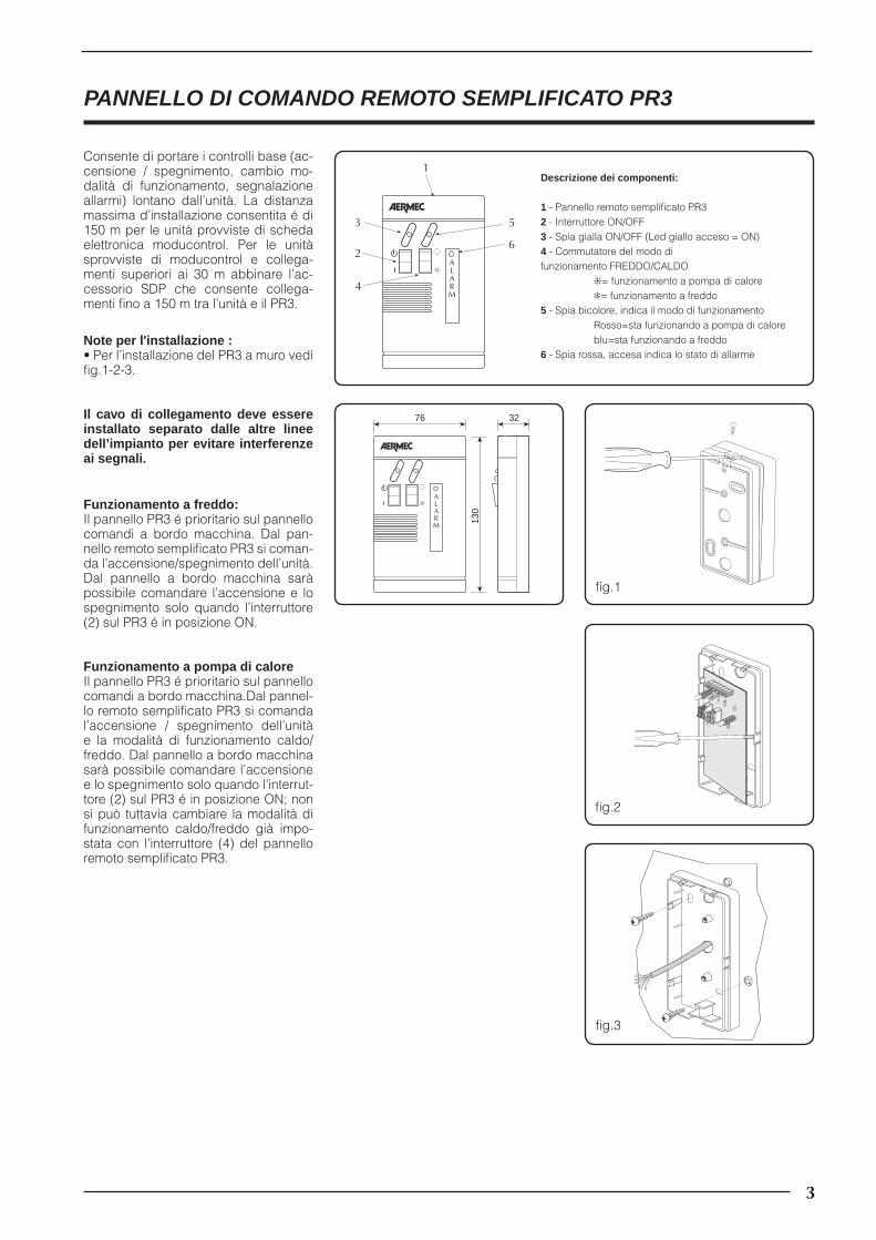
PANNELLO DI COMANDO REMOTO SEMPLIFICATO PR3
Consente di portare i controlli base (ac-censione / spegnimento, cambio mo-dalità di funzionamento, segnalazione allarmi) lontano dall’unità. La distanza massima d’installazione consentita é di 150 m per le unità provviste di scheda elettronica moducontrol. Per le unità sprovviste di moducontrol e collega-menti superiori ai 30 m abbinare l’ac-cessorio SDP che consente collega-menti fi no a 150 m tra l’unità e il PR3.
Note per l'installazione :• Per l’installazione del PR3 a muro vedi fi g.1-2-3.
Il cavo di collegamento deve essere installato separato dalle altre linee dell’impianto per evitare interferenze ai segnali.
32
130
76
ALARM
fi g.1
fi g.2
Funzionamento a freddo:Il pannello PR3 é prioritario sul pannello comandi a bordo macchina. Dal pan-nello remoto semplifi cato PR3 si coman-da l’accensione/spegnimento dell’unità. Dal pannello a bordo macchina sarà possibile comandare l’accensione e lo spegnimento solo quando l’interruttore (2) sul PR3 é in posizione ON.
Funzionamento a pompa di caloreIl pannello PR3 é prioritario sul pannello comandi a bordo macchina.Dal pannel-lo remoto semplifi cato PR3 si comanda l’accensione / spegnimento dell’unità e la modalità di funzionamento caldo/freddo. Dal pannello a bordo macchina sarà possibile comandare l’accensione e lo spegnimento solo quando l’interrut-tore (2) sul PR3 é in posizione ON; non si può tuttavia cambiare la modalità di funzionamento caldo/freddo già impo-stata con l’interruttore (4) del pannello remoto semplifi cato PR3.
fi g.3
ALARM
1
2
4
3 5
6
Descrizione dei componenti:
1 - Pannello remoto semplifi cato PR32 - Interruttore ON/OFF3 - Spia gialla ON/OFF (Led giallo acceso = ON)4 - Commutatore del modo di funzionamento FREDDO/CALDO ❊= funzionamento a pompa di calore ❄= funzionamento a freddo5 - Spia bicolore, indica il modo di funzionamento Rosso=sta funzionando a pompa di calore blu=sta funzionando a freddo6 - Spia rossa, accesa indica lo stato di allarme
3
PR3_new.indd 3 24/06/2009 12.07.56

�� � �� ��� �� �� � ��
� � � � �
��
��
��
�� ��
�� ���
Collegamenti elettrici
MAX 30 m
Collegamento PR3 - Unità con MICROCHILLER, distanza massima 30 metri
• E’ necessario l’utilizzo di un cavo a 7 poli + schermo, con sezione di almeno 0,5 mm2.
• I collegamenti devono essere eseguiti tra la morsettiera del pannello PR3 e la corrispondente morsettiera di rinvio sulla macchina, seguendo lo schema allegato.
• Collegare lo schermo del cavo al segnale GND presente sul polo 8A della morsettiera di rinvio.
• La distanza massima di collegamento in queste condi-zioni è di 30 m
AE = Contatto allarmi
COM = Comune
IA = Contatto interruttore ausiliario
C/F = Segnale comando stagione
� � � � �
��
��
��
�� ��
�� �����
�
�
�
�
�
��
�
�
�
�
�
��
�
��
��
���
��
�
SDP
MA
X 1
m
MA
X 1
50 m
• Per distanze superiori a 30 m e fi no ad un massimo di 150 m occorre interporre la scheda SDP. L’accessorio SDP va montato a bordo macchina all’interno del quadro elettrico.
• Per questo tipo di collegamento non è necessario colle-gare lo schermo del cavo.
Collegamento PR3 - Unità con MICROCHILLER, distanza massima 150 metri
4
PR3_new.indd 4 24/06/2009 12.07.57

� � � � �
��
� � � � �
���
MAX 30 m
Collegamento PR3 - Unità con GR3, distanza massima 30 metri
• E’ necessario l’utilizzo di un cavo a 6 poli con sezione di almeno 0,5 mm2. Non è richiesta la schermatura del cavo.
• I collegamenti devono essere eseguiti tra la morsettiera del pannello PR3 e la corrispondente morsettiera M7 pre-sente sulla scheda GR3.
• In fase di collegamento è obbligatorio eseguire un ponti-cello sulla morsettiera del PR3 tra il polo 1 e il polo 2, come indicato da schema.
• La distanza massima di collegamento in queste condi-zioni è di 30 m
IAD = Contatto interruttore ausiliario
� � � � �
��
�
�
�
�
�
��
�
�
�
�
�
��
��
�
��
SDP
MA
X 1
m
MA
X 1
50 m
• Per distanze superiori a 30 m e fi no ad un massimo di 150 m occorre interporre la scheda SDP. L’accessorio SDP va montato a bordo macchina all’interno del quadro elettrico.
• In questo caso il ponticello da eseguire è tra il polo 1 e il polo 5 della scheda SDP, lato macchina. Tra pannello PR3 e scheda SDP il collegamento è da eseguire punto-punto.
Collegamento PR3 - Unità con GR3, distanza massima 150 metri
5
PR3_new.indd 5 24/06/2009 12.07.57

��
�
���
���
�
�
� � � � �
���
���
����
����
��
�� ��
�� ���
Collegamento PR3 - Unità con MODUCONTROL
• E’ necessario l’utilizzo di un cavo a 7 poli con sezione di almeno 0,5 mm2. Non è necessario lo schermo.
• collegamenti devono essere eseguiti tra la morsettiera del pannello PR3 e la corrispondente morsettiera di rinvio sulla macchina, seguendo lo schema allegato.
• La distanza massima di collegamento in queste condi-zioni è di 150 m.
AE-N = Contatto allarmi (Neutro)
AE-L = Contatto allarmi (Linea)
COM = Comune
IA = Contatto interruttore ausiliario
C/F = Segnale comando stagione
TRA = Contatto cambio stagione
TWS = Contatto termostato acqua sanitaria
MA
X 1
50 m
6
PR3_new.indd 6 24/06/2009 12.07.57

DO NOT wet the packaging DO NOT walk on the packaging Handle with care
Safety symbols
�Voltage hazard Attention Moving parts hazard
Precautions and Safety Standards
Keep the manuals in a dry place, in order to prevent deterioration, for at least 10 years for any further reference.Read all of the information contained in this manual carefully and completely. Pay particular attention to the user regulations accompanied by “DANGER” or “ATTENTION” in so much as, if not complied with, the machine or objects may be damaged and/or persons injured. For the anomalies not contemplates by this manual, contact the area After-sales Service as soon as possible. The apparatus must be installed in such a way that maintenance and/or repair operations are possible.
The appliance warranty does not cover the costs for ladders, scaffolding, or other elevation systems that may become necessary for carrying out servicing under warranty. AERMEC S.p.A. declines all responsibility for any damage due to im-proper use of the machine, partial or hasty reading of the information contained in this manual.
Attention: this product contains electric and electronic appliances that cannot be disposed of through normal municipal collection chan-nels. There are special collection centres for these products.
The electric and electronic appliances must be treated separately and in compliance with the laws in force in the country of use. Batteries and accumulators present in the appliances must be disposed of separately according to the provisions of the municipality of use.
Indications regarding disposal Notes regarding the manuals
Notes regarding the CE Declaration of Conformity
The accessory described in this manual can only be used when coupled with the machines for which it has been designed. On satisfying this condition, the CE Declaration of Conformity of the appliance onto which it is integrated is valid. To control the list
of the compatible accessories, refer to the manual supplied with the unit.
7
PR3_new.indd 7 24/06/2009 12.07.57

PR3 SIMPLIFIED REMOTE CONTROL PANEL
Allows to take the basic controls (switch-on/off, change functioning mode, alarm signals) away from the unit. The maxi-mum installation distance allowed is 150 m for the units with moducontrol circuit board. For units without modu-control and connections exceeding 30 m couple the SDP accessory that allows connections up to 150m between the unit and the PR3.
Notes regarding installation:• For the wall installation of the PR3, see fi g. 1-2-3.
The connection cable must be in-stalled separately from the other sys-tem lines in order to prevent interfer-ence to the signals.
32
130
76
ALARM
fi g.1
fi g.2
Functioning in cooling mode:The PR3 panel has priority over the con-trols on the machine. Unit switch-on/off is commanded from the PR3 simplifi ed remote control panel. It is only possible to command switch-on/off from the pan-el on the machine when the switch (2) on the PR3 is in the ON position.
Functioning in heat pump modeThe PR3 panel has priority over the con-trol panel on the machine. Unit switch-on/off and the cooling/heating function-ing modes are commanded from the PR3 simplifi ed remote control panel. It will be possible to command switch-on/off from the panel on the machine only when the switch (2) on the PR3 is in po-sition ON. The heating/cooling function-ing mode that is already set using the switch (4) on the PR3 simplifi ed remote control panel cannot be changed.
fi g.3
ALARM
1
2
4
3 5
6
Description of components:
1 - PR3 simplifi ed remote panel2 - ON/OFF switch3 - Yellow ON/OFF indicator (Yellow LED on = ON)4 - COOLING/HEATING functioning mode switch-over ❊= functioning in heat pump mode ❄= functioning in cooling mode5 - Two-colour indicator, indicates the functioning mode Red = the heat pump is functioning Blue=it is functioning in cooling mode6 - Red indicator, on indicates the alarm status
8
PR3_new.indd 8 24/06/2009 12.07.58

�� � �� ��� �� �� � ��
� � � � �
��
��
��
�� ��
�� ���
Electric connections
MAX 30 m
PR3 - Unit with MICROCHILLER connection, maximum distance 30 metres
• A 7-pole cable + shield must be used with section of at least 0.5 mm2.
• The connections must be made between the PR3 panel terminal board and the corresponding terminal board on the machine, following the attached diagram.
• Connect the cable shield to the GND signal present on pole 8A of the return terminal board.
• The maximum connection distance in these conditions is 30 m.
AE = Alarms contact
COM = Common
IA = Auxiliary switch contact
C/F = Season command signal
� � � � �
��
��
��
�� ��
�� �����
�
�
�
�
�
��
�
�
�
�
�
��
�
��
��
���
��
�
SDP
MA
X 1
m
MA
X 1
50 m
• For distances exceeding 30 m and up to a maximum of 150 m the SDP board must be positioned. The SDP acces-sory must be mounted on the machine inside the electric control board.
• The cable shield does not have to be connected for this type of connection.
PR3 - Unit with MICROCHILLER connection, maximum distance 150 metres
9
PR3_new.indd 9 24/06/2009 12.07.58
� � � � �
��
� � � � �
���
MAX 30 m
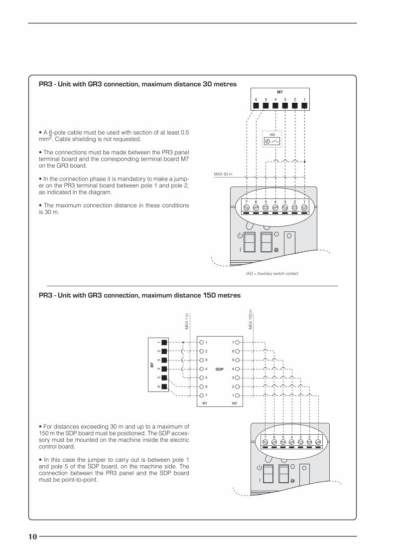
PR3 - Unit with GR3 connection, maximum distance 30 metres
• A 6-pole cable must be used with section of at least 0.5 mm2. Cable shielding is not requested.
• The connections must be made between the PR3 panel terminal board and the corresponding terminal board M7 on the GR3 board.
• In the connection phase it is mandatory to make a jump-er on the PR3 terminal board between pole 1 and pole 2, as indicated in the diagram.
• The maximum connection distance in these conditions is 30 m.
IAD = Auxiliary switch contact
� � � � �
��
�
�
�
�
�
��
�
�
�
�
�
��
��
�
��
SDP
MA
X 1
m
MA
X 1
50 m
• For distances exceeding 30 m and up to a maximum of 150 m the SDP board must be positioned. The SDP acces-sory must be mounted on the machine inside the electric control board.
• In this case the jumper to carry out is between pole 1 and pole 5 of the SDP board, on the machine side. The connection between the PR3 panel and the SDP board must be point-to-point.
PR3 - Unit with GR3 connection, maximum distance 150 metres
10
PR3_new.indd 10 24/06/2009 12.07.59
��
�
���
���
�
�
� � � � �
���
���
����
����
��
�� ��
�� ���
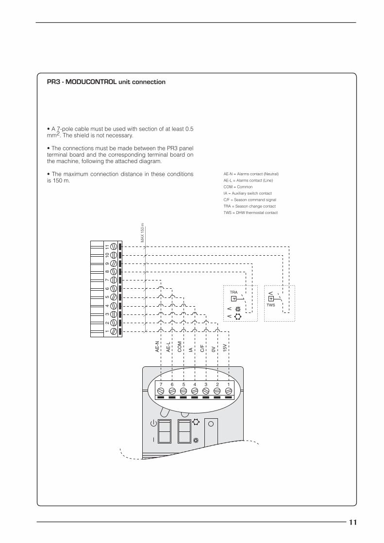
PR3 - MODUCONTROL unit connection
• A 7-pole cable must be used with section of at least 0.5 mm2. The shield is not necessary.
• The connections must be made between the PR3 panel terminal board and the corresponding terminal board on the machine, following the attached diagram.
• The maximum connection distance in these conditions is 150 m.
AE-N = Alarms contact (Neutral)
AE-L = Alarms contact (Line)
COM = Common
IA = Auxiliary switch contact
C/F = Season command signal
TRA = Season change contact
TWS = DHW thermostat contact
MA
X 1
50 m
11
PR3_new.indd 11 24/06/2009 12.07.59

NE PAS mouiller l'emballage NE PAS marcher sur l'emballage Manipuler avec prudence
Symboles de sécurité
�Danger tension Attention Danger éléments en mouvement
Précautions et normes de sécurité
Pour éviter leur détérioration, conserver les manuels dans un lieu sec, pendant au moins 10 ans, pour d’éventuelles références futures.Lire attentivement et complètement toutes les informations contenues dans ce manuel. Faire particulièrement attention aux normes d’utilisation accompagnées des inscrip-tions “DANGER” ou “ATTENTION ” car, si elles ne sont pas respectées, elles peuvent provoquer un dommage à la machine et/ou aux personnes et aux choses. Pour toute anomalie qui n'est pas prévue dans ce manuel, s’adresser en temps utile au Service d’Assistance local. L'appareil doit être installé de façon à pouvoir effectuer les opéra-tions de maintenance et/ou de réparation.
La garantie de l’appareil ne couvre en aucun cas les coûts dérivant des échelles mécaniques, des échafaudages ou d’autres systèmes de levage qui pourraient être nécessaires pour effectuer les interventions sous garantie. AERMEC S.p.A. décline toute responsabilité pour tout dommage dérivant d’une utilisation impropre de la machine, d’une lecture partielle ou superficielle des informations contenues dans ce manuel.
Attention: ce produit contient des appareils électriques et électroniques qui ne peuvent être éliminées par les collectes ordinaires des déchets municipaux. Il existe des centres de collecte différenciée pour ces produits.
Les appareils électriques et électroniques doi-vent être traités séparément et selon les législa-tions en vigueur dans l’état d’appartenance. Les batteries ou les accumulateurs présents dans les appareils doivent être éliminés séparément selon les dispositions de la commune d’appartenance.
Indications sur l'élimination Remarques sur les manuels
Note sulla dichiarazione di conformità CE
L'accessoire décrit dans ce manuel ne peut être utilisé que s'il est combiné avec les machines pour lesquelles il a été conçu: S'il remplit cette condition, la déclaration de conformité CE de l'appa-reil sur lequel il sera intégré est valable. Pour contrôler la liste des
accessoires compatibles, consulter le manuel fourni avec l'unité.
12
PR3_new.indd 12 24/06/2009 12.07.59
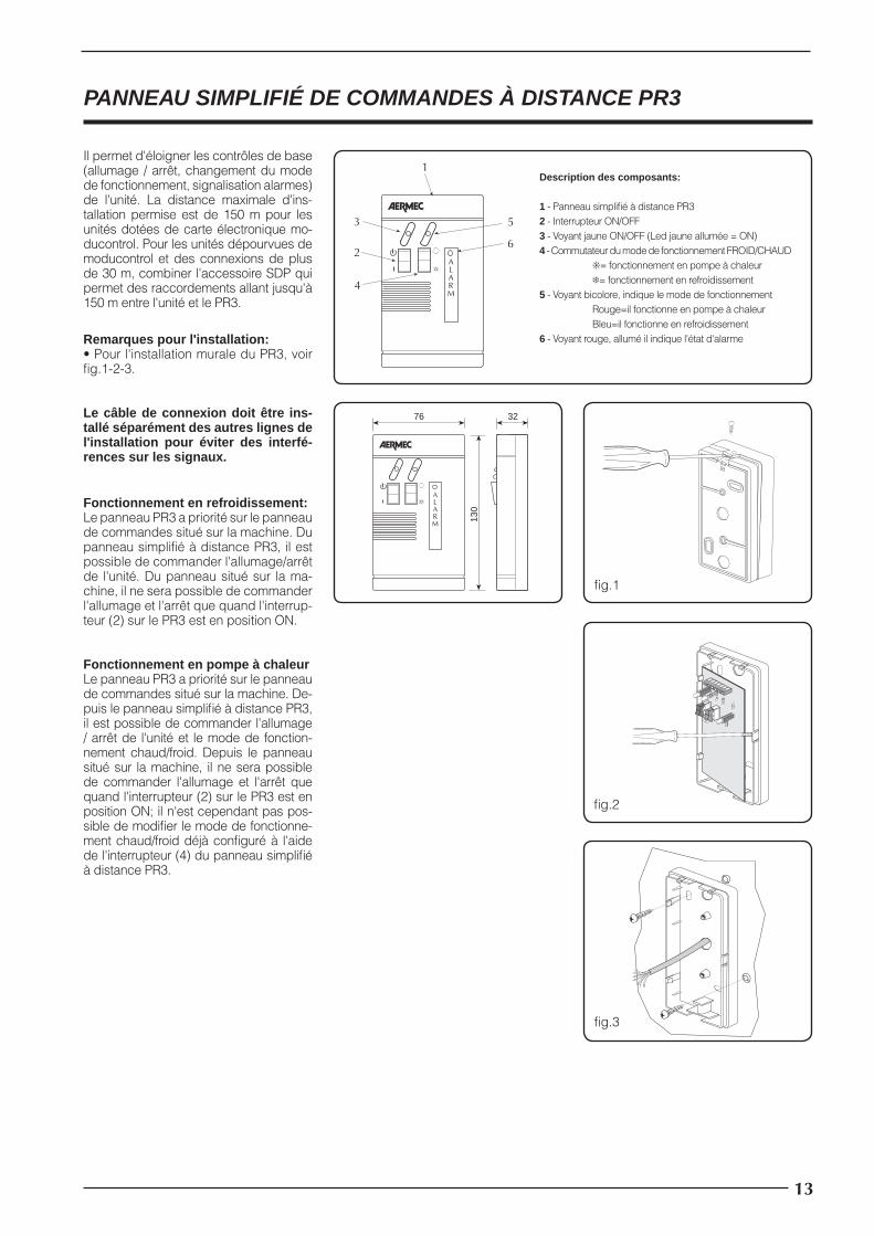
PANNEAU SIMPLIFIÉ DE COMMANDES À DISTANCE PR3
Il permet d'éloigner les contrôles de base (allumage / arrêt, changement du mode de fonctionnement, signalisation alarmes) de l'unité. La distance maximale d'ins-tallation permise est de 150 m pour les unités dotées de carte électronique mo-ducontrol. Pour les unités dépourvues de moducontrol et des connexions de plus de 30 m, combiner l'accessoire SDP qui permet des raccordements allant jusqu'à 150 m entre l'unité et le PR3.
Remarques pour l'installation:• Pour l'installation murale du PR3, voir fi g.1-2-3.
Le câble de connexion doit être ins-tallé séparément des autres lignes de l'installation pour éviter des interfé-rences sur les signaux.
32
130
76
ALARM
fi g.1
fi g.2
Fonctionnement en refroidissement:Le panneau PR3 a priorité sur le panneau de commandes situé sur la machine. Du panneau simplifi é à distance PR3, il est possible de commander l'allumage/arrêt de l'unité. Du panneau situé sur la ma-chine, il ne sera possible de commander l'allumage et l'arrêt que quand l'interrup-teur (2) sur le PR3 est en position ON.
Fonctionnement en pompe à chaleurLe panneau PR3 a priorité sur le panneau de commandes situé sur la machine. De-puis le panneau simplifi é à distance PR3, il est possible de commander l'allumage / arrêt de l'unité et le mode de fonction-nement chaud/froid. Depuis le panneau situé sur la machine, il ne sera possible de commander l'allumage et l'arrêt que quand l'interrupteur (2) sur le PR3 est en position ON; il n'est cependant pas pos-sible de modifi er le mode de fonctionne-ment chaud/froid déjà confi guré à l'aide de l'interrupteur (4) du panneau simplifi é à distance PR3.
fi g.3
ALARM
1
2
4
3 5
6
Description des composants:
1 - Panneau simplifi é à distance PR32 - Interrupteur ON/OFF3 - Voyant jaune ON/OFF (Led jaune allumée = ON)4 - Commutateur du mode de fonctionnement FROID/CHAUD ❊= fonctionnement en pompe à chaleur ❄= fonctionnement en refroidissement5 - Voyant bicolore, indique le mode de fonctionnement Rouge=il fonctionne en pompe à chaleur Bleu=il fonctionne en refroidissement6 - Voyant rouge, allumé il indique l'état d'alarme
13
PR3_new.indd 13 24/06/2009 12.07.59
�� � �� ��� �� �� � ��
� � � � �
��
��
��
�� ��
�� ���
Branchements électriques
MAX 30 m
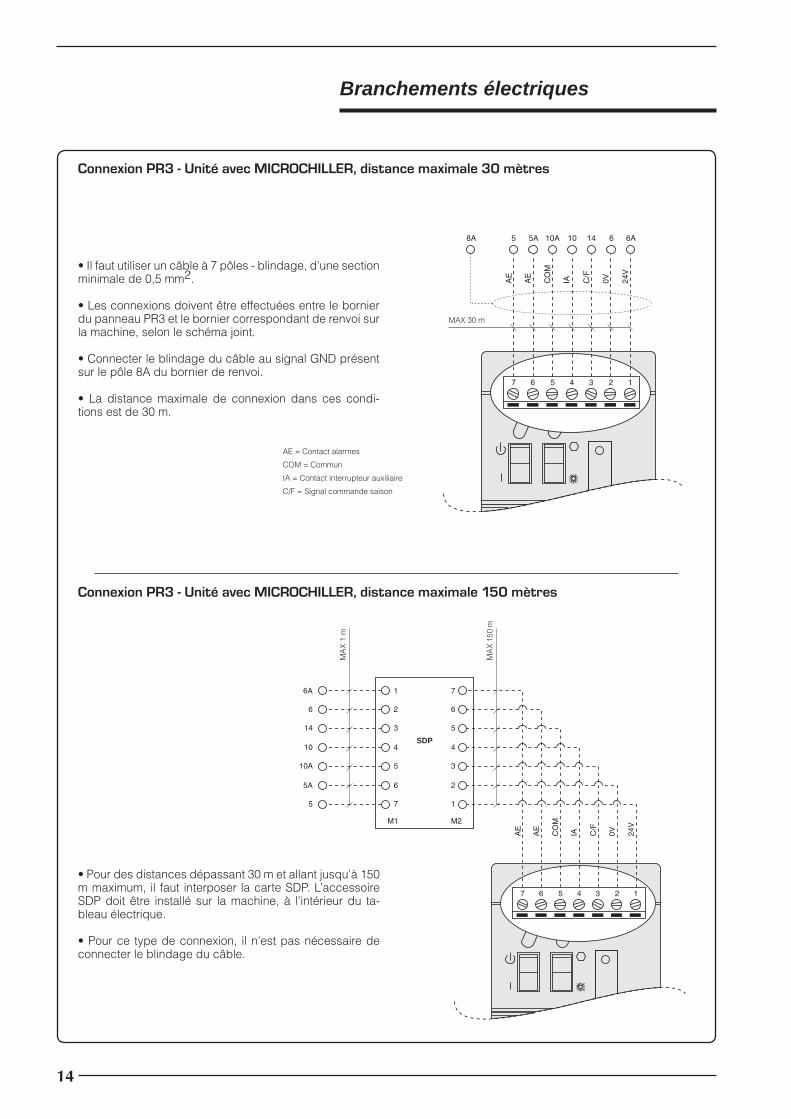
Connexion PR3 - Unité avec MICROCHILLER, distance maximale 30 mètres
• Il faut utiliser un câble à 7 pôles - blindage, d'une section minimale de 0,5 mm2.
• Les connexions doivent être effectuées entre le bornier du panneau PR3 et le bornier correspondant de renvoi sur la machine, selon le schéma joint.
• Connecter le blindage du câble au signal GND présent sur le pôle 8A du bornier de renvoi.
• La distance maximale de connexion dans ces condi-tions est de 30 m.
AE = Contact alarmes
COM = Commun
IA = Contact interrupteur auxiliaire
C/F = Signal commande saison
� � � � �
��
��
��
�� ��
�� �����
�
�
�
�
�
��
�
�
�
�
�
��
�
��
��
���
��
�
SDP
MA
X 1
m
MA
X 1
50 m
• Pour des distances dépassant 30 m et allant jusqu'à 150 m maximum, il faut interposer la carte SDP. L’accessoire SDP doit être installé sur la machine, à l'intérieur du ta-bleau électrique.
• Pour ce type de connexion, il n'est pas nécessaire de connecter le blindage du câble.
Connexion PR3 - Unité avec MICROCHILLER, distance maximale 150 mètres
14
PR3_new.indd 14 24/06/2009 12.08.00

� � � � �
��
� � � � �
���
MAX 30 m
Connexion PR3 - Unité avec GR3, distance maximale 30 mètres
• Il faut utiliser un câble à 6 pôles, d'une section minimale de 0,5 mm2. Le blindage du câble n'est pas nécessaire.
• Les connexions doivent être effectuées entre le bornier du panneau PR3 et le bornier correspondant M7 situé sur la carte GR3.
• Au moment de la connexion, il est obligatoire d'effectuer un pontage sur le bornier du PR3 entre le pôle 1 et le pôle 2, comme indiqué sur le schéma.
• La distance maximale de connexion dans ces condi-tions est de 30 m.
IAD = Contact interrupteur auxiliaire
� � � � �
��
�
�
�
�
�
��
�
�
�
�
�
��
��
�
��
SDP
MA
X 1
m
MA
X 1
50 m
• Pour des distances dépassant 30 m et allant jusqu'à 150 m maximum, il faut interposer la carte SDP. L’accessoire SDP doit être installé sur la machine, à l'intérieur du tableau électrique.
• Dans ce cas, le pontage à effectuer est entre le pôle 1 et le pôle 5 de la carte SDP, côté machine. Entre le panneau PR3 et la carte SDP, la connexion doit être effectuée point-point.
Connexion PR3 - Unité avec GR3, distance maximale 150 mètres
15
PR3_new.indd 15 24/06/2009 12.08.00

��
�
���
���
�
�
� � � � �
���
���
����
����
��
�� ��
�� ���
Connexion PR3 - Unité avec MODUCONTROL
• Il faut utiliser un câble à 7 pôles, d'une section minimale de 0,5 mm2. Le blindage n'est pas nécessaire.
• Les connexions doivent être effectuées entre le bornier du panneau PR3 et le bornier correspondant de renvoi sur la machine, selon le schéma joint.
• La distance maximale de connexion dans ces condi-tions est de 150 m.
AE-N = Contact alarmes (Neutre)
AE-L = Contact alarmes (Ligne)
COM = Commun
IA = Contact interrupteur auxiliaire
C/F = Signal commande saison
TRA = Contact changement de saison
TWS = Contact thermostat eau sanitaire
MA
X 1
50 m
16
PR3_new.indd 16 24/06/2009 12.08.00
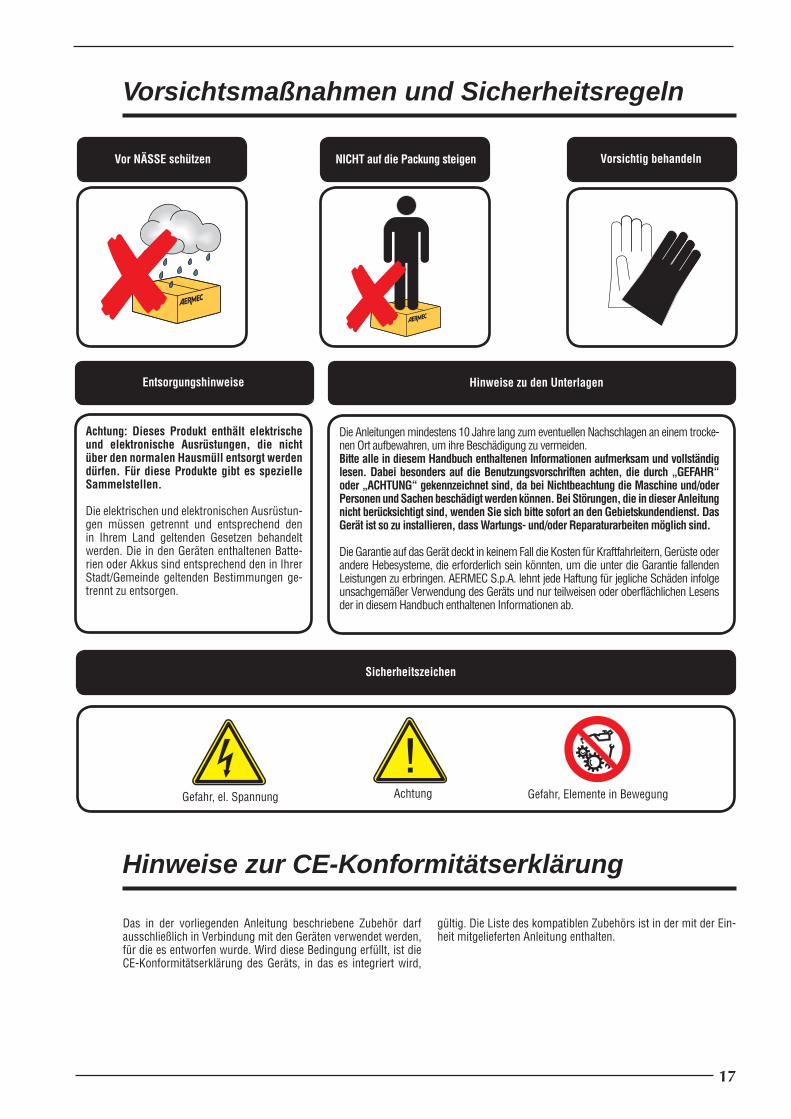
Vor NÄSSE schützen NICHT auf die Packung steigen Vorsichtig behandeln
Sicherheitszeichen
�Gefahr, el. Spannung Achtung Gefahr, Elemente in Bewegung
Vorsichtsmaßnahmen und Sicherheitsregeln
Die Anleitungen mindestens 10 Jahre lang zum eventuellen Nachschlagen an einem trocke-nen Ort aufbewahren, um ihre Beschädigung zu vermeiden.Bitte alle in diesem Handbuch enthaltenen Informationen aufmerksam und vollständig lesen. Dabei besonders auf die Benutzungsvorschriften achten, die durch „GEFAHR“ oder „ACHTUNG“ gekennzeichnet sind, da bei Nichtbeachtung die Maschine und/oder Personen und Sachen beschädigt werden können. Bei Störungen, die in dieser Anleitung nicht berücksichtigt sind, wenden Sie sich bitte sofort an den Gebietskundendienst. Das Gerät ist so zu installieren, dass Wartungs- und/oder Reparaturarbeiten möglich sind.
Die Garantie auf das Gerät deckt in keinem Fall die Kosten für Kraftfahrleitern, Gerüste oder andere Hebesysteme, die erforderlich sein könnten, um die unter die Garantie fallenden Leistungen zu erbringen. AERMEC S.p.A. lehnt jede Haftung für jegliche Schäden infolge unsachgemäßer Verwendung des Geräts und nur teilweisen oder oberflächlichen Lesens der in diesem Handbuch enthaltenen Informationen ab.
Achtung: Dieses Produkt enthält elektrische und elektronische Ausrüstungen, die nicht über den normalen Hausmüll entsorgt werden dürfen. Für diese Produkte gibt es spezielle Sammelstellen.
Die elektrischen und elektronischen Ausrüstun-gen müssen getrennt und entsprechend den in Ihrem Land geltenden Gesetzen behandelt werden. Die in den Geräten enthaltenen Batte-rien oder Akkus sind entsprechend den in Ihrer Stadt/Gemeinde geltenden Bestimmungen ge-trennt zu entsorgen.
Entsorgungshinweise Hinweise zu den Unterlagen
Hinweise zur CE-Konformitätserklärung
Das in der vorliegenden Anleitung beschriebene Zubehör darf ausschließlich in Verbindung mit den Geräten verwendet werden, für die es entworfen wurde. Wird diese Bedingung erfüllt, ist die CE-Konformitätserklärung des Geräts, in das es integriert wird,
gültig. Die Liste des kompatiblen Zubehörs ist in der mit der Ein-heit mitgelieferten Anleitung enthalten.
17
PR3_new.indd 17 24/06/2009 12.08.00

VEREINFACHTE FERNSTEUERUNGSTAFEL PR3
Erlaubt die Fernsteuerung der Grund-funktionen (Ein-/Ausschalten, Umschal-ten der Betriebsart, Alarmanzeige). Die maximal zulässige Installationsentfer-nung beträgt 150 m für Einheiten mit der Steuerkarte Moducontrol. Für Einheiten ohne Moducontrol und Verbindungen über 30 m ist das Zubehör SDP einzu-setzen, mit dem Verbindungen bis 150 m zwischen Einheit und PR3 möglich sind.
Hinweise zur Installation:• Zur Installation des PR3 an der Wand siehe Abb.1/2/3.
Das Anschlusskabel muss getrennt von anderen Leitungen der Anlage verlegt werden, um Interferenzen der Signale zu vermeiden.
32
130
76
ALARM
Abb.1
Abb.2
Kühlbetrieb:Die Bedientafel PR3 hat Vorrang vor der Bedientafel am Gerät. Über die vereinfachte Fernsteuerungstafel PR3 kann das Ein-/Ausschalten der Einheit gesteuert werden. Über die Bedientafel am Gerät kann das Ein- und Ausschal-ten nur gesteuert werden, wenn der Schalter (2) am PR3 auf ON steht.
WärmepumpenbetriebDie Bedientafel PR3 hat Vorrang vor der Bedientafel am Gerät. Über die vereinfachte Fernsteuerungstafel PR3 kann das Ein-/Ausschalten der Einheit und die Betriebsarten Heizen/Kühlen gesteuert werden. Über die Bedienta-fel am Gerät kann das Ein- und Aus-schalten nur gesteuert werden, wenn der Schalter (2) am PR3 auf ON steht; nicht geändert werden kann die bereits mit dem Schalter (4) der vereinfachten Fernsteuerungstafel PR3 eingestellte Betriebsart Heizen/Kühlen.
Abb.3
ALARM
1
2
4
3 5
6
Beschreibung der Bauteile:
1 - Vereinfachte Fernsteuerungstafel PR32 - Schalter ON/OFF3 - Gelbe Leuchte ON/OFF (Gelbe LED leuchtet = ON)4 - Umschalter der Betriebsart KÜHLEN/HEIZEN ❊= Wärmepumpenbetrieb ❄= Kühlbetrieb5 - Zweifarbige Leuchte, zeigt Betriebsart an Rot = Wärmepumpenbetrieb Blau = Kühlbetrieb6 - Rote Leuchte, zeigt Alarmzustand an
18
PR3_new.indd 18 24/06/2009 12.08.01

�� � �� ��� �� �� � ��
� � � � �
��
��
��
�� ��
�� ���
Elektrische Anschlüsse
MAX 30 m
Verbindung PR3 - Einheit mit MICROCHILLER, Maximalabstand 30 Meter
• Es ist ein 7-adriges Kabel mit Abschirmung und mindestens 0,5 mm2 Querschnitt einzusetzen.
• Die Verbindungen müssen zwischen der Klemmleiste der Bedientafel PR3 und der entsprechenden Anschluss-Klemm-leiste am Gerät gemäß beiliegendem Schaltplan erfolgen.
• Abschirmung des Kabels mit dem Signal GND an Anschluss 8A der Anschluss-Klemmleiste verbinden.
• Unter diesen Bedingungen beträgt der maximale Verbin-dungsabstand 30 m.
AE = Alarmkontakt
COM = Gemeinsamer Leiter
IA = Kontakt Nebenschalter
C/F = Jahreszeit-Steuersignal
� � � � �
��
��
��
�� ��
�� �����
�
�
�
�
�
��
�
�
�
�
�
��
�
��
��
���
��
�
SDP
MA
X 1
m
MA
X 1
50 m
• Für Entfernungen über 30 m und bis maximal 150 m ist die Zusatzkarte SDP zwischenzuschalten. Das Zubehör SDP ist am Gerät im Schaltschrank zu montieren.
• Bei dieser Verbindungsart ist der Anschluss der Kabel-abschirmung nicht erforderlich.
Verbindung PR3 - Einheit mit MICROCHILLER, Maximalabstand 150 Meter
19
PR3_new.indd 19 24/06/2009 12.08.01
� � � � �
��
� � � � �
���
MAX 30 m
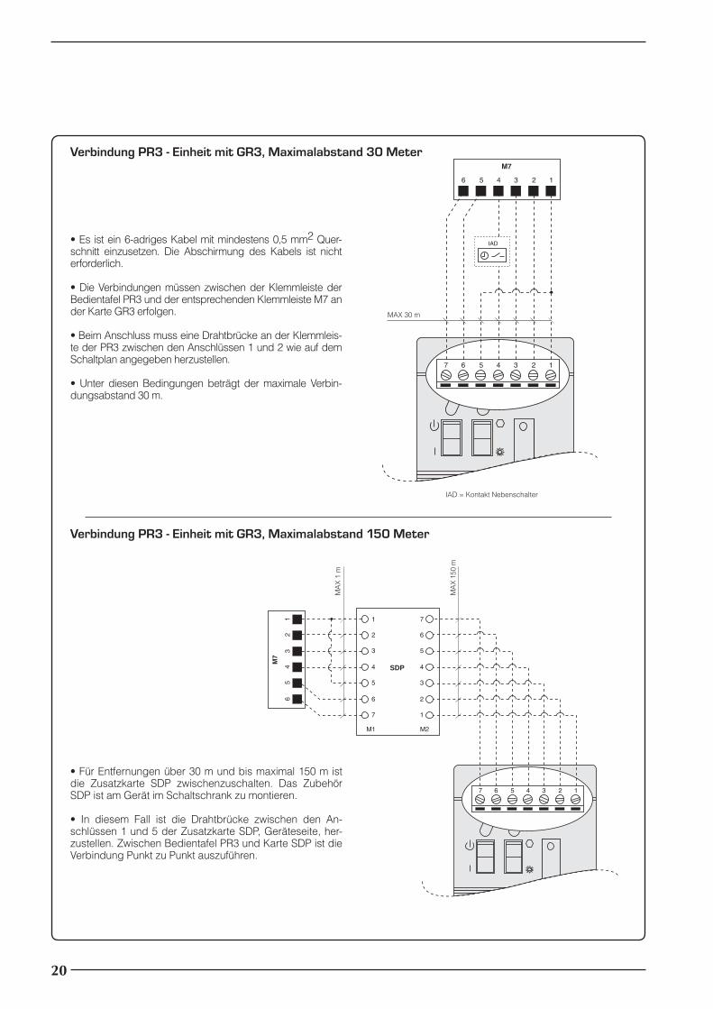
Verbindung PR3 - Einheit mit GR3, Maximalabstand 30 Meter
• Es ist ein 6-adriges Kabel mit mindestens 0,5 mm2 Quer-schnitt einzusetzen. Die Abschirmung des Kabels ist nicht erforderlich.
• Die Verbindungen müssen zwischen der Klemmleiste der Bedientafel PR3 und der entsprechenden Klemmleiste M7 an der Karte GR3 erfolgen.
• Beim Anschluss muss eine Drahtbrücke an der Klemmleis-te der PR3 zwischen den Anschlüssen 1 und 2 wie auf dem Schaltplan angegeben herzustellen.
• Unter diesen Bedingungen beträgt der maximale Verbin-dungsabstand 30 m.
IAD = Kontakt Nebenschalter
� � � � �
��
�
�
�
�
�
��
�
�
�
�
�
��
��
�
��
SDP
MA
X 1
m
MA
X 1
50 m
• Für Entfernungen über 30 m und bis maximal 150 m ist die Zusatzkarte SDP zwischenzuschalten. Das Zubehör SDP ist am Gerät im Schaltschrank zu montieren.
• In diesem Fall ist die Drahtbrücke zwischen den An-schlüssen 1 und 5 der Zusatzkarte SDP, Geräteseite, her-zustellen. Zwischen Bedientafel PR3 und Karte SDP ist die Verbindung Punkt zu Punkt auszuführen.
Verbindung PR3 - Einheit mit GR3, Maximalabstand 150 Meter
20
PR3_new.indd 20 24/06/2009 12.08.01

��
�
���
���
�
�
� � � � �
���
���
����
����
��
�� ��
�� ���
Verbindung PR3 - Einheit mit MODUCONTROL
• Es ist ein 7-adriges Kabel mit mindestens 0,5 mm2 Quer-schnitt einzusetzen. Die Abschirmung ist nicht erforderlich.
• Die Verbindungen müssen zwischen der Klemmleiste der Bedientafel PR3 und der entsprechenden Anschluss-Klemmleiste am Gerät gemäß beiliegendem Schaltplan er-folgen.
• Unter diesen Bedingungen beträgt der maximale Verbin-dungsabstand 150 m.
AE-N = Alarmkontakt (Nullleiter)
AE-L = Alarmkontakt (Leitung)
COM = Gemeinsamer Leiter
IA = Kontakt Nebenschalter
C/F = Jahreszeit-Steuersignal
TRA = Jahreszeitumschaltkontakt
TWS = Thermostatkontakt Trinkwassererwärmung
MA
X 1
50 m
21
PR3_new.indd 21 24/06/2009 12.08.02

NO moje el embalaje NO pise el embalaje Maneje con cuidado
Símbolos de seguridad
�Peligro tensión Atención Peligro órganos en movimiento
Precauciones y normas de seguridad
Conserve los manuales en un lugar seco, a fi n de evitar que se deterioren, durante, por lo menos, 10 años para eventuales consultas futuras.Lea atenta y completamente todas las informaciones que contiene este manual. Preste especial atención a las normas de utilización que están acompañadas del mensaje “PELIGRO” o bien “ATENCIÓN”, ya que, si no se respetan, pueden cau-sar daños a la máquina y/o a las personas y cosas. Para las anomalías que no se contemplan en este manual, hay que ponerse en contacto inmediatamente con el Servicio de Asistencia de la zona. Se debe instalar el equipo de manera tal que sea posible llevar a cabo las operaciones de mantenimiento y/o reparación.
La garantía del equipo no cubre, en ningún caso, los costes debidos a la autoescalera, andamiajes u otros sistemas de elevación que sean necesarios para llevar a cabo las inter-venciones en garantía. AERMEC S.p.A. declina toda responsabilidad por daños debidos a una utilización impropia de la máquina, como así también a una lectura parcial o superficial de las informaciones que contiene este manual.
Atención: este producto contiene equipos eléc-tricos y electrónicos que no se pueden eliminar mediante los normales canales de recogida de los desechos municipales. Existen centros de recogida diferenciada para estos productos.
Los equipos eléctricos y electrónicos se deben tratar por separado y según las legislaciones vi-gentes en el estado de pertenencia. Las baterías o los acumuladores que están presentes en los equipos se deben eliminar por separado, según las disposiciones del ayuntamiento de pertenen-cia.
Indicaciones sobre la eliminación Notas sobre los manuales
Notas sobre la declaración de conformidad CE
El accesorio descrito en este manual se puede utilizar única y ex-clusivamente en conjunto con las máquinas para las que ha sido proyectado. Si se satisface esta condición, vale la declaración de conformidad CE del equipo en el que se integrará. Para controlar
la lista de los accesorios compatibles, consulte el manual propor-cionado con la unidad.
22
PR3_new.indd 22 24/06/2009 12.08.02
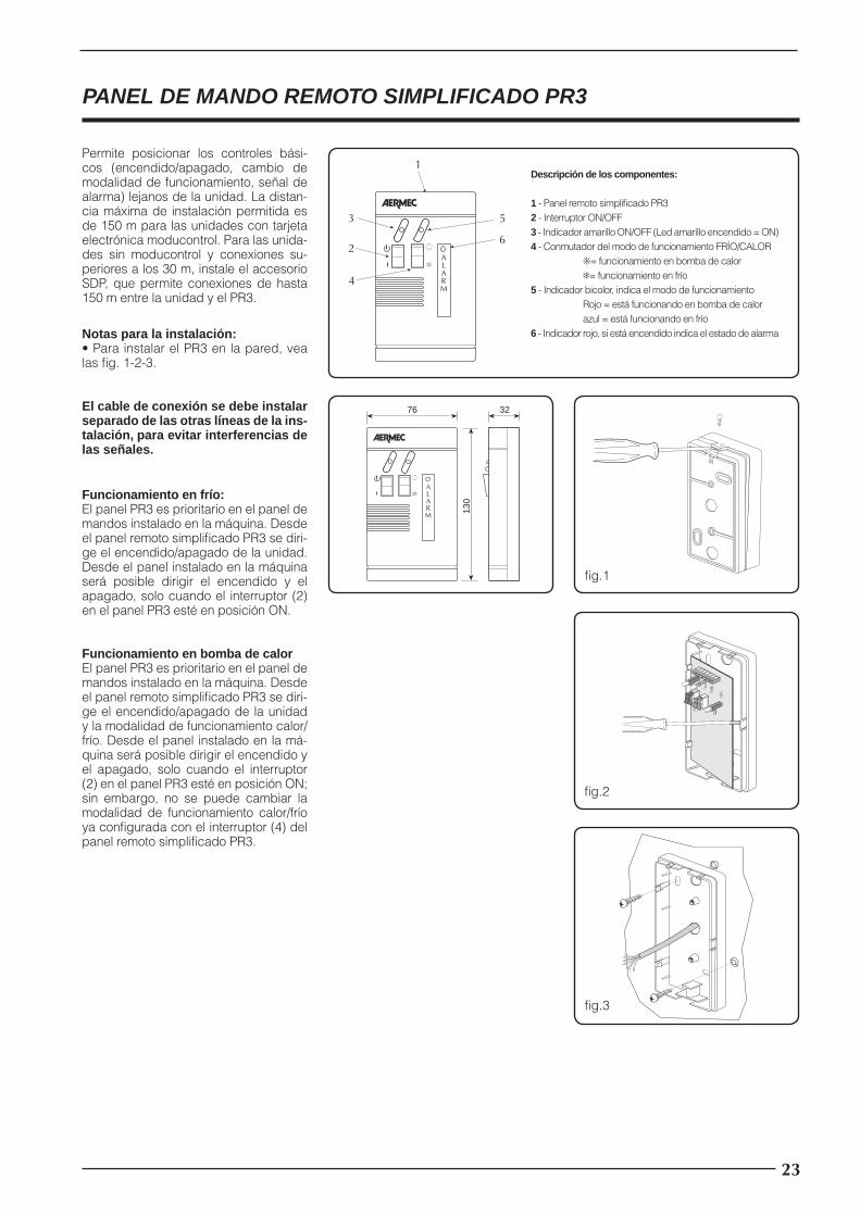
PANEL DE MANDO REMOTO SIMPLIFICADO PR3
Permite posicionar los controles bási-cos (encendido/apagado, cambio de modalidad de funcionamiento, señal de alarma) lejanos de la unidad. La distan-cia máxima de instalación permitida es de 150 m para las unidades con tarjeta electrónica moducontrol. Para las unida-des sin moducontrol y conexiones su-periores a los 30 m, instale el accesorio SDP, que permite conexiones de hasta 150 m entre la unidad y el PR3.
Notas para la instalación:• Para instalar el PR3 en la pared, vea las fi g. 1-2-3.
El cable de conexión se debe instalar separado de las otras líneas de la ins-talación, para evitar interferencias de las señales.
32
130
76
ALARM
fi g.1
fi g.2
Funcionamiento en frío:El panel PR3 es prioritario en el panel de mandos instalado en la máquina. Desde el panel remoto simplifi cado PR3 se diri-ge el encendido/apagado de la unidad. Desde el panel instalado en la máquina será posible dirigir el encendido y el apagado, solo cuando el interruptor (2) en el panel PR3 esté en posición ON.
Funcionamiento en bomba de calorEl panel PR3 es prioritario en el panel de mandos instalado en la máquina. Desde el panel remoto simplifi cado PR3 se diri-ge el encendido/apagado de la unidad y la modalidad de funcionamiento calor/frío. Desde el panel instalado en la má-quina será posible dirigir el encendido y el apagado, solo cuando el interruptor (2) en el panel PR3 esté en posición ON; sin embargo, no se puede cambiar la modalidad de funcionamiento calor/frío ya confi gurada con el interruptor (4) del panel remoto simplifi cado PR3.
fi g.3
ALARM
1
2
4
3 5
6
Descripción de los componentes:
1 - Panel remoto simplifi cado PR32 - Interruptor ON/OFF3 - Indicador amarillo ON/OFF (Led amarillo encendido = ON)4 - Conmutador del modo de funcionamiento FRÍO/CALOR ❊= funcionamiento en bomba de calor ❄= funcionamiento en frío5 - Indicador bicolor, indica el modo de funcionamiento Rojo = está funcionando en bomba de calor azul = está funcionando en frío6 - Indicador rojo, si está encendido indica el estado de alarma
23
PR3_new.indd 23 24/06/2009 12.08.02

�� � �� ��� �� �� � ��
� � � � �
��
��
��
�� ��
�� ���
Conexiones eléctricas
MÁX. 30 m
Conexión PR3 - Unidad con MICROCHILLER, distancia máxima de 30 metros
• Es necesario usar un cable de 7 polos + pantalla, con sección de al menos 0,5 mm2.
• Las conexiones se deben hacer entre el bornero del panel PR3 y el bornero correspondiente de reenvío en la máquina, siguiendo el esquema anexo.
• Conecte la pantalla del cable a la señal GND presente en el polo 8A del bornero de reenvío.
• La distancia máxima de conexión en estas condiciones es de 30 m.
AE = Contacto alarmas
COM = Común
IA = Contacto interruptor auxiliar
C/F = Señal de mando estación
� � � � �
��
��
��
�� ��
�� �����
�
�
�
�
�
��
�
�
�
�
�
��
�
��
��
���
��
�
SDP
MÁ
X 1
m
MÁ
X 1
50 m
• Para distancias superiores a 30 m y hasta un máximo de 150 m, se debe interponer la tarjeta SDP. El acceso-rio SDP se debe montar en la máquina dentro del cuadro eléctrico.
• Para este tipo de conexión no es necesario conectar la pantalla del cable.
Conexión PR3 - Unidad con MICROCHILLER, distancia máxima de 150 metros
24
PR3_new.indd 24 24/06/2009 12.08.03

� � � � �
��
� � � � �
���
MÁX 30 m
Conexión PR3 - Unidad con GR3, distancia máxima de 30 metros
• Es necesario usar un cable de 6 polos, con sección de al menos 0,5 mm2. No es necesario el cable apantallado.
• Las conexiones se deben hacer entre el bornero del pa-nel PR3 y el bornero correspondiente M7 presente en la tarjeta GR3.
• En fase de conexión es obligatorio realizar un puente en el bornero del PR3 entre el polo 1 y el polo 2, como se indica en el esquema.
• La distancia máxima de conexión en estas condiciones es de 30 m.
IAD = Contacto interruptor auxiliar
� � � � �
��
�
�
�
�
�
��
�
�
�
�
�
��
��
�
��
SDP
MÁ
X 1
m
MÁ
X 1
50 m
• Para distancias superiores a 30 m y hasta un máximo de 150 m, se debe interponer la tarjeta SDP. El accesorio SDP se debe montar en la máquina dentro del cuadro eléctrico.
• En este caso el puente a realizar es entre el polo 1 y el polo 5 de la tarjeta SDP, en el lado máquina. Entre el panel PR3 y la tarjeta SDP la conexión se debe realizar punto-punto.
Conexión PR3 - Unidad con GR3, distancia máxima de 150 metros
25
PR3_new.indd 25 24/06/2009 12.08.03

��
�
���
���
�
�
� � � � �
���
���
����
����
��
�� ��
�� ���
Conexión PR3 - Unidad con MODUCONTROL
• Es necesario usar un cable de 7 polos, con sección de al menos 0,5 mm2. No es necesaria la pantalla.
• Las conexiones se deben hacer entre el bornero del panel PR3 y el bornero correspondiente de reenvío en la máquina, siguiendo el esquema anexo.
• La distancia máxima de conexión en estas condiciones es de 150 m.
AE-N = Contacto alarmas (Neutro)
AE-L = Contacto alarmas (Línea)
COM = Común
IA = Contacto interruptor auxiliar
C/F = Señal de mando estación
TRA = Contacto cambio de estación
TWS = Contacto termostato agua sanitaria
MÁ
X 1
50 m
26
PR3_new.indd 26 24/06/2009 12.08.03

27
PR3_new.indd 27 24/06/2009 12.08.03

I dati tecnici riportati nella presente documentazione non sono impegnativi.AERMEC S.p.A. si riserva la facoltà di apportare in qualsiasi momento tutte le modifi-che ritenute necessarie per il miglioramento del prodotto.
Technical data shown in this booklet are not binding.AERMEC S.p.A. shall have the right to introduce at any time whatever modifications deemed necessary to the improvement of the product.
Les données mentionnées dans ce manuel ne constituent aucun engagement de notre part. AERMEC S.p.A. se réserve le droit de modifier à tous moments les données con-sidérées nécessaires à l' amelioration du produit.
Im Sinne des technischen Fortschrittes behält sich AERMEC S.p.A. vor, in der Produktion Änderungen und Verbesserungen ohne Ankündigung durchzuführen.
AERMEC S.p.A. se reserva el derecho de modificarlos en cualquier momento lle-vado por la necesidad de mejorar el producto. Los datos técnicos que se reproducen en este documento no son vinculantes.AERMEC S.p.A. se reserva el derecho de modificarlos en cualquier momento llevado por la necesidad de mejorar el producto.
PR3_new.indd 28 24/06/2009 12.08.03